opcon in-ground conversion kit for stanley magic … · assembly & installation manual opcon...
TRANSCRIPT

ASSEMBLY & INSTALLATION MANUAL
OPCON IN-GROUND CONVERSION KITFOR STANLEY MAGIC FORCE
Go to www.opconusa.com for shop drawings,architectural details, technical details, hardware,product links and other related information.
© 2016 OpconUSA ALL RIGHTS RESERVED

INDEX
TITLE Page
THEORY OF OPERATION & IMPORTANT CONSIDERATIONS 3 ISOMETRIC DRAWING WITH PARTS IDENTIFICATION 4
ASSEMBLY PROCEDURE
OPERATOR ASSEMBLY (Procedure 1) 5 CHAIN AND SPROCKET ASSEMBLY (Procedure 2) 6 CHAIN TENSIONING & TUNING (Procedure 3) 7 SPINDLE CENTERING & WEDGING (Procedure 4) 8 SPINDLE HEIGHT ADJUSTMENT (Procedure 5) 9
SEALING
CEMENT CASE & SPINDLE SEALS (Procedure 6) 10
FLOOR BLOCKOUT TEMPLATES
CENTER HUNG 11 3/4 ” OFFSET PIVOT HUNG (Standard Arms – Under Jamb Mount) 12 BUTT HUNG (HINGED) (Bottom Slide Arm – Within Jambs) 13
INSTALLATION PROCEDURES
CENTER HUNG DOORS 14 3/4 ” OFFSET PIVOT HUNG DOORS (Under Jamb Mount) 15 BUTT HUNG (HINGED) DOORS 16
WIRING AND ELECTRICAL
ELECTRIC & LOW VOLTAGE CONDUIT CONNECTIONS 17 WIRING REQUIREMENTS – LIQUID TIGHT FITTING DETAILS 18 WIRING REQUIREMENTS – STANDARD INSTALLATION 19 WIRING REQUIREMENTS – ELECTRIC PANIC DEVICE 20 WIRING REQUIREMENTS – OVERHEAD ELECTRIC LOCK 21 WIRING REQUIREMENTS – BOTTOM ELECTRIC LOCK 22 WARRANTY 23/24

OPERATOR CONVERSTION THEORY
& IMPORTANT CONSIDERATIONS
(REVIEW BEFORE STARTING ASSEMBLY AND INSTALLATION)
THEORY OF OPERATION
The Opcon Operator Conversion System is designed to convert standard overhead mounted, swing door operators from overhead mounted to underground/underfloor use. A custom pivot assembly and operator-mounting sled is provided to attach the standard operator, creating a new drive assembly. The entire drive assembly is then placed into a waterproof cement case, sealed, and cemented into place under the door. The drive system Spindle attaches to the bottom arm of the door. The Spindle profile of the unit integrates with many available bottom arms for center hung and offset hung swing doors.
CONSIDERATIONS
1) HANDING: It is important to note that handing the operator is opposite of standard since the operator is mounted upside down when converted. Specifically, a left hand operator swings a right hand door; and a right hand operator swings a left hand door. Microswitch placement, stop block placement, and programming functions will be affected depending upon the operator selected.
2) DRIVE SPINDLE: The Spindle of the converter is specific to the bottom arm selected for each door. Spindle profiles are available for most Dorma and Rixson bottom arm hardware for center hung, offset pivot hung, and offset butt hung (hinged) doors. Bottom arms are NOT supplied with the converter. Be certain that the Spindle ordered matches the bottom arm selected. See Opcon website for details.
3) CEMENT CASE SIZE: All cement cases are supplied at the standard size of 35-1/2” long X 7” wide. On pairs of doors, a conduit connects the cement cases and the width is variable. Pairs of doors narrower than 72” are available as a custom order. Contact Opcon for custom size details.
4) FLOOR & PREPARATION: The typical floor depth for the converter is 7” minimum. Center hung door excavation is the width between the jambs. Offset hung door excavation is the width between the jambs + 2” under the pivot side jambs.
5) THRESHOLD & FLOORING: Most thresholds must be 10” wide to cover the converter and excavation. Terrazzo/stone pans have a variable size between 8” and 10”. Thresholds made to Opcon specifications are available directly from National Guard Products. Terrazzo & Stone Pans are also available for stone flooring directly from Opcon. Refer to Thresholds at website.
6) ELECTRICAL & LOW VOLTAGE: The electrical supply and low voltage signal lines must enter the cement case at the non-pivot side of the converter on single doors, and at or near the center on pairs of doors. Liquid Tight conduit fittings must be installed. Wireless activation requires sealed antennae placement through the cement case. Refer to Wiring section of the Install Manual.
3

STANLEY MAGIC FORCE
3K
6
1D
5
1A
7
2L
PTN. DESCRIPTION 1A CEMENT CASE 1B SPINDLE SEAL 1C 1D PERIMETER GASKET
2A SLED BASE 2B MOTOR MOUNT BRACKET (2) 2C-T FRONT PIVOT HOUSING RISER 2D-T REAR PIVOT HOUSING RISER 2E BASE PLATE 2F/G TOP PLATE/LAT BUSHING
3A PIVOT ARM SPINDLE 3B SPINDLE SPROCKET 3C SHAFT KEY 3D-1 STD. ANTI-SLIP COLLAR F/KEY 3E "O" -RING 3F BEARING COVER 3G TAPERED BEARING
4A DRIVE SPROCKET 4B THRUST WASHER 4C NEEDLE BEARING 4D THRUST WASHER
5 DRIVE CHAIN OR BELT
CEMENT CASE COVER
3D-2 ALT. ANTI-SLIP COLLAR F/KEY
1E 1F CASE COUPLER F/PAIRS 1G CONDUIT CONNECTOR
2H LOWER TENSIONER STOP 2J BASE PLATE BOLT (2) 2K LATERAL WEDGES (4) 2L LATERAL HEX WEDGE
3K THRESHOLD SEAL 3L "O" -RING SEAL
6 THRESHOLD ASSY. 7 OPERATOR ASSY.
COUPLER COVER F/SINGLES
4E FLAT WASHER 4F LOCK WASHER 4G HEX BOLT
2M UPPER CHAIN TENSIONER 2N WEDGE & HANDING BRACKET
3M RETAINING RING
1F
1E
1G
2A
2B2D-T
2E
3A3B
3D-1 3D-23E 3F3G
2F2G
1C1B
4G 4F4E4A
4B
3L
2J2H
2M
© 2016 OpconUSA ALL RIGHTS RESERVED
2K
2C-T
4D 4C
2N
3C
3M
4

OPERATOR ASSEMBLY (PROCEDURE 1)
STANLEY MAGIC FORCE
NOTES/PROCEDURE:1. Reference isometric drawing for more details.2. Right hand outswing shown; uses left hand outswing operator due to upside-down mounting. Program for left-hand outswing.3. After mounting, power operator to 90° open position & set open stop block location.4. See chain and sprocket assembly to continue.
STEP 3: Place sled overoperator & attach with 4 hexbolts. Then slide operatorforward on sled
STEP 1: Remove pan-headscrews at inspection cover.Counter-sink and installflat-head screws. Clearancerequired for spindle seals.
5© 2016 OpconUSA ALL RIGHTS RESERVED
STEP 2: Remove angle wedgeSTEP 4: Replace angle wedge
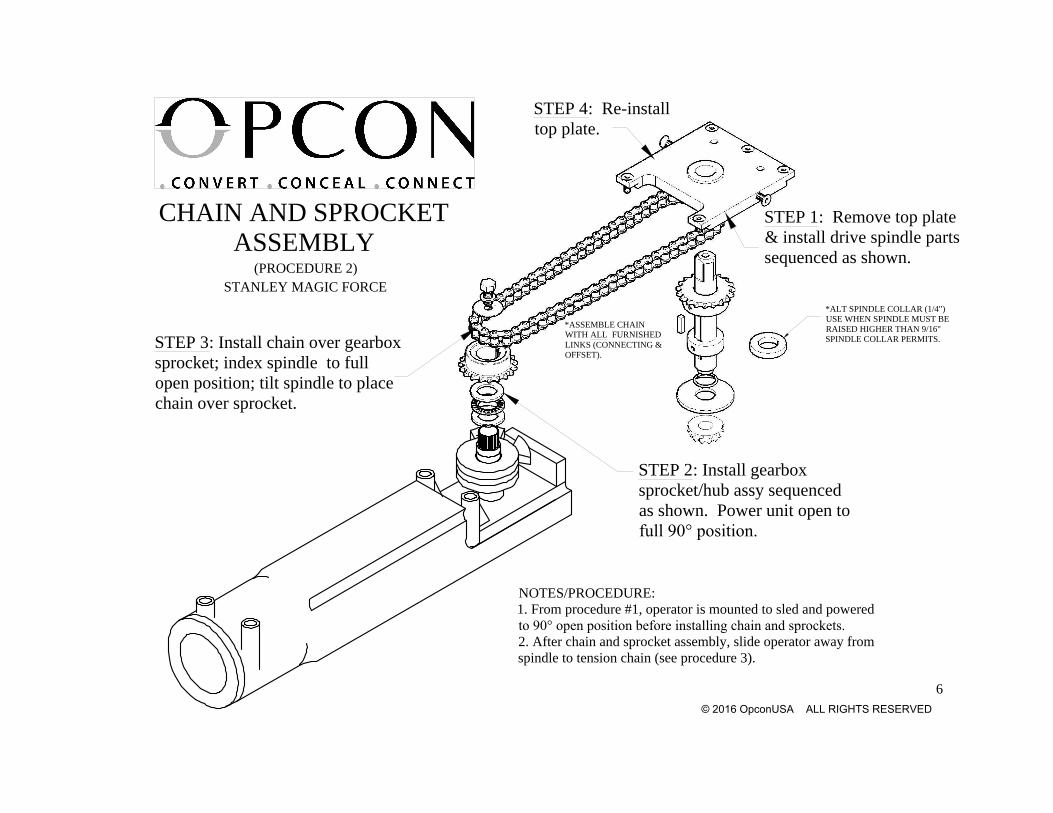
CHAIN AND SPROCKETASSEMBLY
(PROCEDURE 2) STANLEY MAGIC FORCE
NOTES/PROCEDURE:1. From procedure #1, operator is mounted to sled and poweredto 90° open position before installing chain and sprockets.2. After chain and sprocket assembly, slide operator away fromspindle to tension chain (see procedure 3).
STEP 1: Remove top plate& install drive spindle partssequenced as shown.
STEP 2: Install gearboxsprocket/hub assy sequencedas shown. Power unit open tofull 90° position.
STEP 3: Install chain over gearboxsprocket; index spindle to fullopen position; tilt spindle to placechain over sprocket.
STEP 4: Re-installtop plate.
*ALT SPINDLE COLLAR (1/4")USE WHEN SPINDLE MUST BERAISED HIGHER THAN 9/16"SPINDLE COLLAR PERMITS.
*ASSEMBLE CHAINWITH ALL FURNISHEDLINKS (CONNECTING &OFFSET).
6© 2016 OpconUSA ALL RIGHTS RESERVED
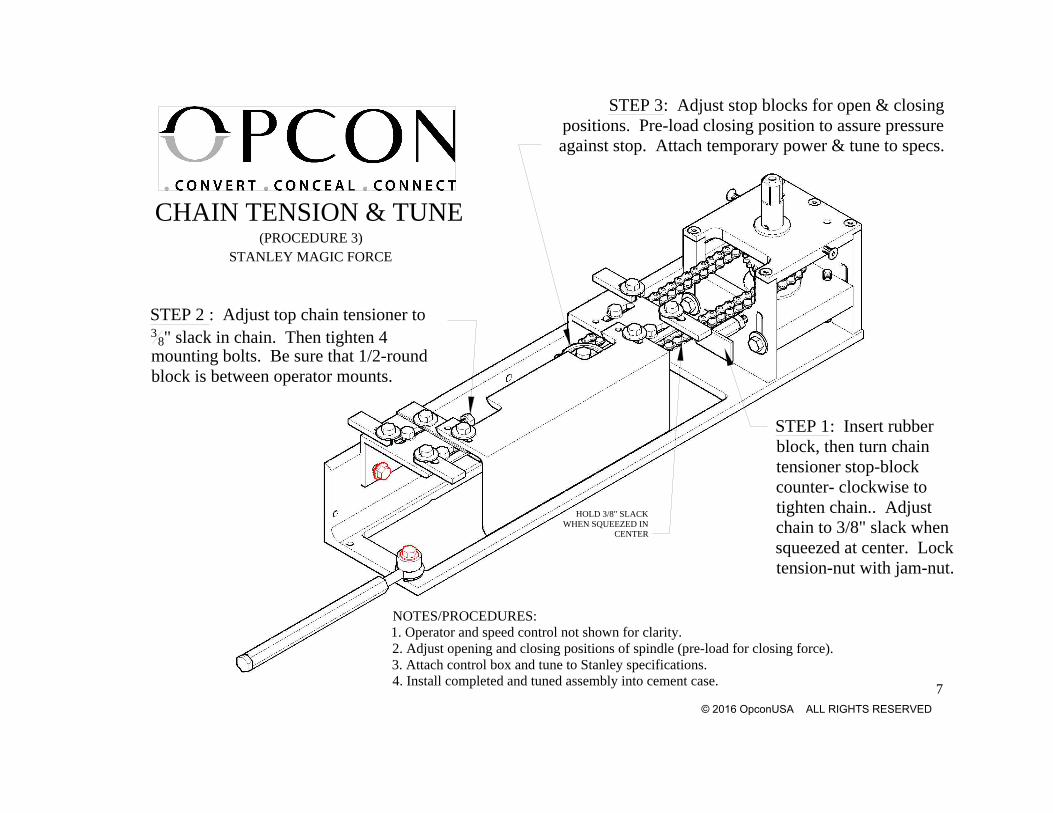
CHAIN TENSION & TUNE (PROCEDURE 3)
STANLEY MAGIC FORCE
STEP 1: Insert rubberblock, then turn chaintensioner stop-blockcounter- clockwise totighten chain.. Adjustchain to 3/8" slack whensqueezed at center. Locktension-nut with jam-nut.
NOTES/PROCEDURES:1. Operator and speed control not shown for clarity.2. Adjust opening and closing positions of spindle (pre-load for closing force).3. Attach control box and tune to Stanley specifications.4. Install completed and tuned assembly into cement case.
HOLD 3/8" SLACKWHEN SQUEEZED IN
CENTER
7© 2016 OpconUSA ALL RIGHTS RESERVED
STEP 3: Adjust stop blocks for open & closingpositions. Pre-load closing position to assure pressureagainst stop. Attach temporary power & tune to specs.
STEP 2 : Adjust top chain tensioner to3
8" slack in chain. Then tighten 4mounting bolts. Be sure that 1/2-roundblock is between operator mounts.

SPINDLE CENTERING &WEDGING
(PROCEDURE 4)STANLEY MAGIC FORCE
STEP 1: Center spindle using 2bolts on top plate. Minimize
pressure on cement case to avoidmisalignment of cover screws.
STEP 2: Adjust hex bar for lateralmovement. Insert shims behindspindle housing for alternate spindlelocating.
STEP 3: Tighten horseshoe wedges at4 places and angle wedge at 2 places.Wedge flat and tight against cementcase and tighten 2 set screws and nuts.
NOTES/PROCEDURES:1. Operator and speed control not shown for clarity.2. Insert tuned converter/operator assembly into cement case.3. Adjust spindle to center of cement case using adjusting bolts and hex bar.4. Wedge sled assembly firmly within cement case. 8
© 2016 OpconUSA ALL RIGHTS RESERVED
ANGLE WEDGE

SPINDLE HEIGHTADJUSTMENT
(PROCEDURE 5) STANLEY MAGIC FORCE
STEP 1: Loosen (2) 9/16" baseplate bolts. Do not remove.
STEP 2: Adjust base-plate height usingAllen wrench on 3 threaded posts. Turn
clockwise to raise; turn counter-clockwiseto lower. Turn each post equally.
STEP 3: Re-tighten (2) 9/16"base plate bolts.
Spindleshoulder
9© 2016 OpconUSA ALL RIGHTS RESERVED

CEMENT CASE ANDSPINDLE SEALS
(PROCEDURE 6)
STEP 2: Install plasticseal and "O" ring afterinstalling floor cover.INSTALL PRIOR TOHANGING DOOR.
STEP 1: Seal entireperimeter of floor coverwith silicone sealant.DO NOT SCREWINTO CEMENT CASECOVER.
*Perimeter sealfactory installed.
*Electricalpenetrations requireliquid-tite fittings
10© 2016 OpconUSA ALL RIGHTS RESERVED

FIELD LAYOUT TEMPLATEFLOOR BLOCKOUTCENTER HUNG DOORS
SINGLE DOOR : LEFT HAND OUTSWING (RHR) SHOWNRIGHT HAND OUTSWING (LHR) OPPOSITE
OUTSWING DOOR PAIRNOTES1. CENTER HUNG DOORS ONLY. DIMENSIONS DIFFERENT ON OFFSET PIVOT AND BUTT HUNG DOORS2. SEE MANUFACTURERS TEMPLATE FOR LATEST DOOR LEAF AND BOTTOM ARM PREP3. DEPTH OF EXCAVATION IS 7" MINIMUM BELOW FINISHED FLOOR4. SPINDLE CENTER MUST BE PLUMB WITH TOP PIVOT
*EXTRA CLEARANCE MAYBE REQUIRED AT LIQUID
TIGHT ELEC. FITTINGS
© 2016 OpconUSA ALL RIGHTS RESERVED

FIELD LAYOUT TEMPLATE
SINGLE DOOR : LEFT HAND OUTSWING (RHR) SHOWNRIGHT HAND OUTSWING (LHR) OPPOSITE
OUTSWING DOOR PAIR
FLOOR BLOCKOUT WITH STANDARDBOTTOM ARMS ONLY
(RIXSON #27 OR DORMA BTS-80, ETC.)3/4" OFFSET PIVOT HUNG DOORS ONLY
NOTES1. 3/4" OFFSET PIVOT DOORS USING STANDARD BOTTOM ARMS ONLY. DIMENSIONS DIFFERENT ON BUTT HUNG (HINGED), OFFSET SLIDE-ARM, AND CENTER-HUNG DOORS2. SPINDLE MUST BE PLUMB WITH PIVOT CENTER. SEE MANUFACTURER'S CURRENT TEMPLATE FOR BOTTOM ARM PLACEMENT ON DOOR3. DEPTH OF EXCAVATION IS 7" MINIMUM BELOW FINISHED FLOOR
© 2016 OpconUSA ALL RIGHTS RESERVED
*EXTRA CLEARANCE MAYBE REQUIRED AT LIQUID
TIGHT ELEC. FITTINGS

FIELD LAYOUT TEMPLATEFLOOR BLOCKOUT FOR
BUTT HUNG (HINGED) AND 3/4" OFFSET PIVOT DOORS
USING DORMA BTS-81 BOTTOM ARM & 7451N SLIDE TRACKSINGLE DOOR : LEFT HAND OUTSWING (RHR) SHOWN
RIGHT HAND OUTSWING (LHR) OPPOSITE
OUTSWING DOOR PAIR
NOTES1. BUTT HUNG (HINGED) & 3/4" OFFSET PIVOT DOORS USING DORMA BOTTOM ARM AND SLIDE TRACK2. DIMENSIONS ARE FOR 1-3/4" DOOR THICKNESS. HOLD 1-1/4" DIMENSION FROM INSIDE FACE OF ANY DOOR THICKNESS TO CENTERLINE OF SPINDLE. SPINDLE MAY NOT BE AT CENTERLINE OF JAMB.3. JAMB WIDTHS VARY. PLACEMENT DIMENSIONS ARE FROM INTERIOR FACE OF JAMB TO CENTER OF SPINDLE.4. DEPTH OF EXCAVATION IS 7" MINIMUM BELOW FINISHED FLOOR
*EXTRA CLEARANCE MAYBE REQUIRED AT LIQUID
TIGHT ELEC. FITTINGS

CENTER HUNG DOORS - PAIR
INSTALLATION PROCEDUREALL MANUFACTURERS - ALL STANDARD OPERATORS
CENTER HUNG DOORS2 34" Pivot Setback (Rixson #28, Dorma BTS-80, etc.)
1. Cut concrete or floor to dimensions detailed on blockout/template drawing. Blockout must be entire door width between jambs .2. Layout & drill cement case for electrical & signal lines3. Install electric & low voltage conduit with liquid-tite fittings.4. Install top door pivot & locate center of OPCON converter converter spindle using a plumb-bob/laser.5. Cement case must be parallel with door header.6. For PAIRS of doors the cases will be set separately with a connecting conduit at center.7. Cement case must be level & plumb in all directions.8. Set cement case into excavation & secure in position.9. Pourstone ONLY around bottom 1" of cement case. INSTALL SPINDLE/SHAFT SEALS NOW. Hang door and final adjust position.10. Final pourstone cement case with OPCON converter assembly & door leaf in place.
14© 2016 OpconUSA ALL RIGHTS RESERVED
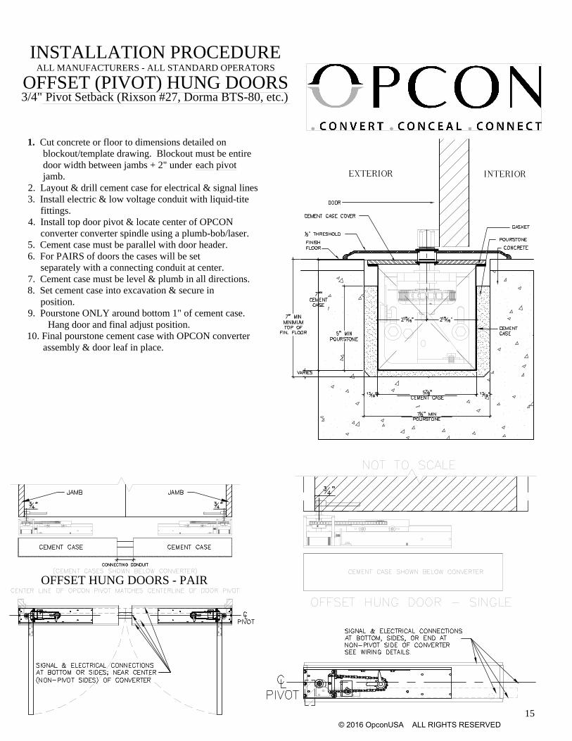
1. Cut concrete or floor to dimensions detailed on blockout/template drawing. Blockout must be entire door width between jambs + 2" under each pivot jamb.2. Layout & drill cement case for electrical & signal lines3. Install electric & low voltage conduit with liquid-tite fittings.4. Install top door pivot & locate center of OPCON converter converter spindle using a plumb-bob/laser.5. Cement case must be parallel with door header.6. For PAIRS of doors the cases will be set separately with a connecting conduit at center.7. Cement case must be level & plumb in all directions.8. Set cement case into excavation & secure in position.9. Pourstone ONLY around bottom 1" of cement case. Hang door and final adjust position.10. Final pourstone cement case with OPCON converter assembly & door leaf in place.
OFFSET HUNG DOORS - PAIR
INSTALLATION PROCEDUREALL MANUFACTURERS - ALL STANDARD OPERATORS
OFFSET (PIVOT) HUNG DOORS3/4" Pivot Setback (Rixson #27, Dorma BTS-80, etc.)
15© 2016 OpconUSA ALL RIGHTS RESERVED
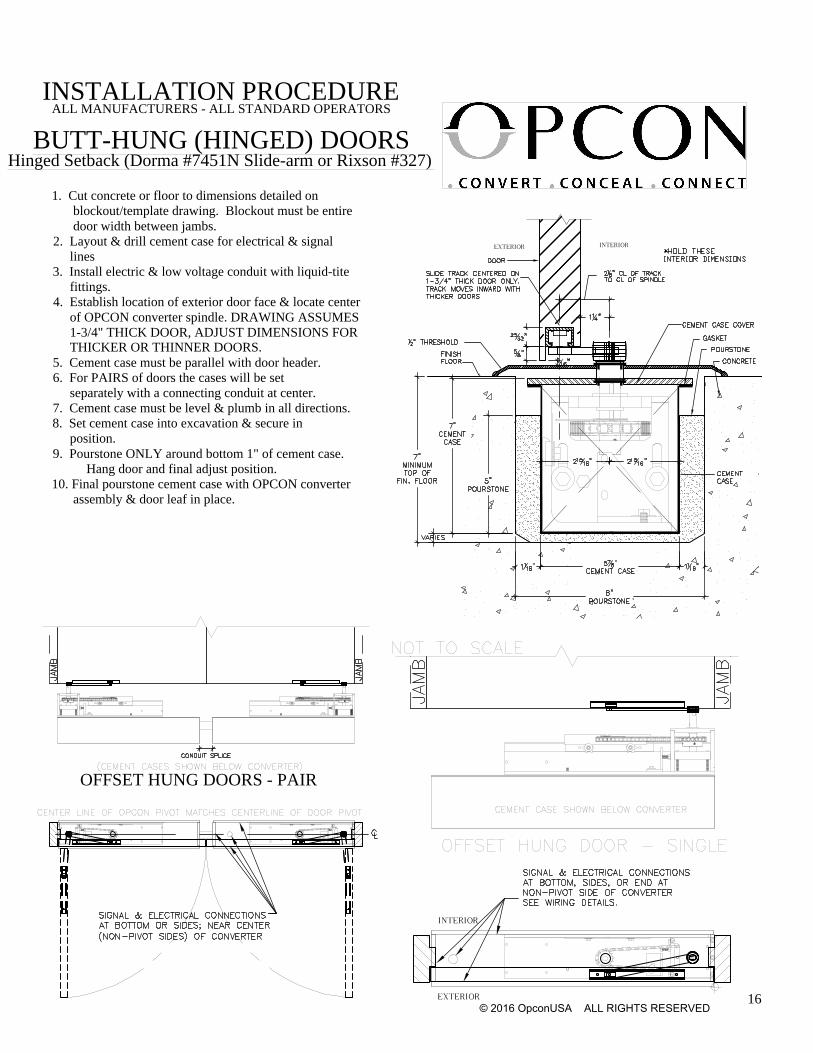
1. Cut concrete or floor to dimensions detailed on blockout/template drawing. Blockout must be entire door width between jambs.2. Layout & drill cement case for electrical & signal lines3. Install electric & low voltage conduit with liquid-tite fittings.4. Establish location of exterior door face & locate center of OPCON converter spindle. DRAWING ASSUMES 1-3/4" THICK DOOR, ADJUST DIMENSIONS FOR THICKER OR THINNER DOORS.5. Cement case must be parallel with door header.6. For PAIRS of doors the cases will be set separately with a connecting conduit at center.7. Cement case must be level & plumb in all directions.8. Set cement case into excavation & secure in position.9. Pourstone ONLY around bottom 1" of cement case. Hang door and final adjust position.10. Final pourstone cement case with OPCON converter assembly & door leaf in place.
OFFSET HUNG DOORS - PAIR
INSTALLATION PROCEDUREALL MANUFACTURERS - ALL STANDARD OPERATORS
BUTT-HUNG (HINGED) DOORSHinged Setback (Dorma #7451N Slide-arm or Rixson #327)
16© 2016 OpconUSA ALL RIGHTS RESERVED

CONDUIT CONNECTIONS
5. Install converter/operator/door assembly. INSTALL SPINDLE SEALS PRIOR TO HANGING DOOR.
6. Install cement case cover/gasket assembly. Do not overtighten screws.
NOTE: Holes with arrows show the best locations for conduit penetrations. Jobsite conditions will dictate actual location. Locations vary by operator.
TYPICAL FOR ALL INSTALLATIONS(Standard System for Single and Dual Cement Cases)
PVC Conduit Connector (provided byOpcon.) Silicone in place (all sides-inside &out) when leveling & prior to pourstone.
17© 2016 OpconUSA ALL RIGHTS RESERVED
ELECTRIC & LOW VOLTAGE LINES
DUAL CASESPower requiredto one case only
EXTERIOR
SINGLECASES
1. Verify power requirements with operator manufacturer & layout cement case for conduit.
2. Verify low voltage signal lines for accessories & layout cement case for conduit.
3. Conduit to cement case connection MUST be OPCON supplied "liguid-tight" water tight fittings specifying Arlington #LT7. Field drilled as required by supplied drawing detail. Conduit & liquid-tight fittings required for both 120VAC and low voltage signal runs.
4. Conduit connections to convertor must be at the strike side of single doors and near center of dual doors as shown. Holes may be located at sides, bottom, or end (on single doors) of cement case. MUST be liguid-tight fittings (Arlington #LT7). Use of other fittings may cause leaks & void warranty.
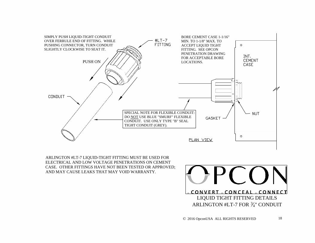
PUSH ON
SIMPLY PUSH LIQUID-TIGHT CONDUITOVER FERRULE END OF FITTING. WHILEPUSHING CONNECTOR, TURN CONDUITSLIGHTLY CLOCKWISE TO SEAT IT.
LIQUID TIGHT FITTING DETAILSARLINGTON #LT-7 FOR 3
4" CONDUIT
ARLINGTON #LT-7 LIQUID-TIGHT FITTING MUST BE USED FORELECTRICAL AND LOW VOLTAGE PENETRATIONS ON CEMENTCASE. OTHER FITTINGS HAVE NOT BEEN TESTED OR APPROVED;AND MAY CAUSE LEAKS THAT MAY VOID WARRANTY.
BORE CEMENT CASE 1-1/16"MIN. TO 1-1/8" MAX. TOACCEPT LIQUID TIGHTFITTING. SEE OPCONPENETRATION DRAWINGFOR ACCEPTABLE BORELOCATIONS.
SPECIAL NOTE FOR FLEXIBLE CONDUIT:DO NOT USE BLUE "SMURF" FLEXIBLECONDUIT. USE ONLY TYPE "B" SEALTIGHT CONDUIT (GREY).
18© 2016 OpconUSA ALL RIGHTS RESERVED

© 2016 OpconUSA ALL RIGHTS RESERVED

© 2016 OpconUSA ALL RIGHTS RESERVED
© 2016 OpconUSA ALL RIGHTS RESERVED

© 2016 OpconUSA ALL RIGHTS RESERVED

OPCON USA, LP
WARRANTY POLICY ON OPCON PRODUCTS
Opcon USA, LP manufactures its products from high-grade materials utilizing only USA craftsmen. Subject to the other conditions of the warranty, if any parts of our own manufacture prove defective in material or workmanship within one (1) year after original installation, we shall repair or replace such parts free of cost. If any equipment or parts not of our own manufacture are utilized in connection with this automatic door operator conversion system, we shall assume responsibility and liability for defects only to the extent of such adjustment as the manufacturer thereof makes to us. The warranty shall not extend beyond one (1) year from the original date of installation regardless of any replacements that may be made. This is a “parts-only” replacement warranty. Field labor for warranty repairs shall be the responsibility of the installing or servicing entity.
Our obligations under the Warranty are conditional upon: (1) the owner’s having filed the Warranty Registration Card with us at the time of the original installments, (2) giving us prompt written notice of alleged defects, and (3) upon our request, returning the allegedly defective items to us in Oceanside, California, freight prepaid, for inspection.
We shall have no obligation or liability, under this Warranty or otherwise, in the event of improper installation of this automatic door operator conversion system unless and until the installation is corrected. However, in no case shall we have any obligation or, liability beyond one (1) year after the original installation for any replacement or repairs that may be made. We reserve the right, without obligation, to inspect all installations of Opcon door operator conversion systems and equipment for the protection of both the owner and ourselves. Only Opcon authorized automatic door installers may install or service the Opcon conversion system and/or the interfaced automatic door operator.
In no event shall we have any obligation or liability, under this Warranty or otherwise, resulting in whole or in part from damage to defects in the door operator or equipment caused by abuse, misuse, malicious mischief, acts of God, casualty, improper handling, pressure washing at or near the equipment, installation/service by non-Opcon authorized technicians, or the negligence of the owner or others. Nor shall we have any obligations or liability for any loss, cost or expense incurred in the repair of replacement of the door operator or equipment except on express written authority from Opcon USA, LP.
The owner’s sole remedy against us for any alleged defects in the Opcon Conversion System shall be as provided in the Warranty. We hereby disclaim all other obligations and liability for damages, including any incidental consequential damages. THIS PARTS-ONLY WARANTY IS IN LIEU OF ALL OTHER WARRANTIES, EXPRESSED OR IMPLIED, INCLUDING ANY IMPLIED WARRANTY OF MERCHANTABILITY OR FITNESS FOR A PARTICULAR PURPOSE. FIELD LABOR WARRANTY IS THE RESPONSIBILITY OF THE OPCON FACTORY AUTHORIZED INSTALLER.
23
OPCON USA, LP
INSTALLATION GUIDELINES AFFECTING WARRANTY
The Opcon cement case enclosure is a UL 50 and CSA 22 listed and labeled, NEMA 4, water-resistant enclosure. Conformance with the following installation and service procedures must be maintained to assure a proper installation and to maintain the Opcon warranty.
1. PENETRATIONS: The cement case must only be penetrated to install electric power service and low voltage signal wires. The Opcon provided (and identified) liquid tight fittings must be used at both penetrations and the fittings may only be placed as detailed in the installation manual. Use of liquid tight fittings is a code requirement by the National Electric Code (NEC) and Opcon specifications. Attachments to the cement case cover are never permitted.
Please note: In certain exterior conditions (downgrade elevation, openings with direct contact to precipitation, extreme humidity or other similar conditions) a drain system or provision form the unit is recommended. In addition, the control unit should be mounted in an n elevated position or remotely located separate from the unit. Condensation resulting from temperature and or climatic conditions is a naturally occurring process and not a warranty provision.
2. SEALS: All seals provided with the Opcon system must be installed including: a. Spindle seal at aluminum cover (pressed in) b. Spindle seal (“d seal”) at threshold c. Perimeter gasket between cement case and cover d. Connector conduit and end plate seals are factory installed and sealed with a special
silicone. Any damage to the silicone seal in these areas must be repaired.
SPECIAL NOTE ON SEALS: ANY SEAL FOUND TO BE DAMAGED OR WORN MUST BE REPLACED IMMEDIDATELY TO MAINTAIN THE UL AND SCA LISTINGS AS WELL AS OPCON SPECIFICATIONS AND WARRANY.
3. FLOOR COVERS (thresholds): All floor covers must be manufactured by Opcon or manufactured to Opcon specifications. Floor covers must be manufactured to accept all seals, must be removable for future service, and must be attached to the surrounding floor without penetrating the cement s case or cement case cover. All floor covers must have a perimeter seal of silicone or similar water proofing sealant applied to keep water from encroaching between the cement case cover and the floor cover.
4. TECHNICIANS: The automatic operator manufacturer and Opcon must certify installation and service technicians. Additionally, technicians must be certified by the American Association of Automatic Door Manufacturers (AAADM). Installing or servicing the Opcon system or automatic operator equipment using non-certified technicians will void this warranty.
5. PRESSURE WASHING is never permitted at or near the Opcon installation.
3052 Industry St, Ste 104 – Oceanside, CA 92054 – (760) 720-3902 – [email protected] – www.opconusa.com