openweather: a peer-to-peer weather data transmission …
TRANSCRIPT

Adrián Yanes
OpenWeather:
A Peer-to-Peer Weather Data Transmission Protocol
Faculty of Electronics, Communications and Automation
Department of Communications and Networking (Comnet)
Thesis submitted for examination for the degree of Master of Science in Technology.
Otaniemi, Espoo, 31.08.2011
Thesis supervisor and instructor: Prof. Jörg OttarX
iv:1
111.
0337
v1 [
cs.N
I] 1
Nov
201
1

Aalto UniversitySchool of Electrical Engineering
Abstract of theMaster’s thesis
Author: Adrián Yanes
Title: OpenWeather: a peer-to-peer weather data transmission protocol
Date: 31.08.2011 Language: English Number of pages: 115 + 23
Faculty of Electronics, Communications and AutomationDepartment of Communication and NetworkingProfessorship: Networking Technology Code: S-38
Supervisor: Prof. Jörg Ott
The study of the weather is performed using instruments termed weather stations.These weather stations are distributed around the world, collecting the data fromthe different phenomena. Several weather organizations have been deployingthousands of these instruments, creating big networks to collect weather data.
These instruments are collecting the weather data and delivering it for laterprocessing in the collections points. Nevertheless, all the methodologies used totransmit the weather data are based in protocols non adapted for this purpose.Thus, the weather stations are limited by the data formats and protocols used inthem, not taking advantage of the real-time data available on them.
We research the weather instruments, their technology and their network capa-bilities, in order to provide a solution for the mentioned problem. OpenWeatheris the protocol proposed to provide a more optimum and reliable way to transmitthe weather data. We evaluate the environmental factors, such as location orbandwidth availability, in order to design a protocol adapted to the requirementsestablished by the automatic weather stations.
A peer to peer architecture is proposed, providing a functional implementationof OpenWeather protocol. The evaluation of the protocol is executed in a realscenario, providing the hints to adapt the protocol to a common automatic weatherstation.
Keywords: P2P, peer to peer, weather stations, real-time, protocol standardiza-tion, embedded system, IETF, RFC

If you want to accomplish something in the world, idealism is notenough, you need to choose a method that works to achieve thegoal. In other words, you need to be “pragmatic”.
Richard Matthew Stallman

License
CC0 1.0 Universal (CC0 1.0)Public Domain Dedication
No Copyright
The person who associated a work with this deed has dedicatedthe work to the public domain by waiving all of his or her rightsto the work worldwide under copyright law, including all relatedand neighboring rights, to the extent allowed by law.
You can copy, modify, distribute and perform the work, even forcommercial purposes, all without asking permission. See OtherInformation below.
Other information
• In no way are the patent or trademark rights of any personaffected by CC0, nor are the rights that other persons mayhave in the work or in how the work is used, such as publicityor privacy rights.
• Unless expressly stated otherwise, the person who associateda work with this deed makes no warranties about the work,and disclaims liability for all uses of the work, to the fullestextent permitted by applicable law.
• When using or citing the work, you should not imply en-dorsement by the author or the affirmer.
This is a human-readable summary of the Legal Code:http://creativecommons.org/publicdomain/zero/1.0/legalcode
Note: this license does not apply for the following parts of this thesis: Figure 2.2,Figure 2.3, Figure 2.4, Figure 3.1, Figure 3.5, Figure 3.7. The copyright of thesefigures belongs to their authors.

Preface
Before I started this thesis, my knowledge about weather stations and the tech-nologies behind them was pretty limited. Nevertheless, in some way the weatherdata transmission got my attention. Probably my preference for open systems,libre software and my passion for network protocols, was the trigger to look for atopic that combines all of these areas.
During this thesis my main goal has been to show how a modern instrument asan automatic weather station, can be improved using concepts brought from openand standard technologies.
Furthermore, the impact that the weather has in our everyday deserves a deeperattention from the engineering point of view. Although the scientists are doing agreat job finding new ways to understand the weather, they really need improve-ments in the technology field, to achieve even more better results.
OpenWeather looks for a digression. This research is looking for the attention of thescientists and the industry; for those vendors that are manufacturing instrumentswithout a common standard, and for those scientists that are experimenting issueswith the weather data acquisition. Both communities must find an agreement tostandardize the methods and the technologies to transmit the weather data.
I truly think that if we start using protocols designed having in consideration thecharacteristics of the weather data, the result of their use will change completelythe vision about what is the weather, what causes it and how it can be predicted.
v

Acknowledgements
Too many people have been involved directly or indirectly in this thesis, however,nothing of this would have happened without the support of my parents, LuisaPilar and José Emilio. Thanks for your support during all these years; from thebeginning you have trusted me blindly, thanks for teaching me the value of theknowledge, I love you.
Thanks to the Aalto University, and especially to professor Jörg Ott, for supervis-ing my thesis.
Thank you to Antti Lauri from the SMEAR project & University of Helsinki, forinviting me to spend a weekend in the premises of the SMEAR project in Tampere,having the possibility to discuss with some engineers and scientists, the issues andparticularities of one of the biggest weather stations in the world. Also thanks toPasi P. Aalto and Erkky Siivola, from the University of Helsinki. Your patienceand experience with weather stations have been really useful to me.
I really need to say a big thanks to Vaisala corporation, especially to Pekka Ko-rhonen and Jing Lin, thanks for providing me with all the necessary hardware-included an amazing last generation weather station- to perform my research andfor the support offered.
A big thank you to Gonzalo Mariscal, for supporting me and my constant requestsduring two years.
Several friends have been involved in all the OpenWeather matters, thanks to theguys of the Polyteknikkojen Radiokerho (Radio Club), to provide me the materialsand the place to install the weather station. Thanks to Jose Azeredo Lima, for hissupport with some of the figures. Thanks to those friends that probably read thisthesis even more times than me: Borja Tarraso, Sergey Vetrogronov and DavidFernández, thanks for your dedication helping me, your support has been reallyimportant for me.
Finally, I want to dedicate this thesis not to one, two or three persons, I want todo it to a community, the community of the libre and open source software. Toall of those developers that are working so hard to make the world a better place,without your work this thesis would never exist: respect.
Otaniemi, Espoo, August 2011.
Adrián.
vi

Contents
1 Introduction 11.1 Background . . . . . . . . . . . . . . . . . . . . . . . . . . . . . . . 21.2 Problem statement . . . . . . . . . . . . . . . . . . . . . . . . . . . 31.3 Research objectives and scope . . . . . . . . . . . . . . . . . . . . . 71.4 Motivations . . . . . . . . . . . . . . . . . . . . . . . . . . . . . . . 71.5 Outline of the thesis . . . . . . . . . . . . . . . . . . . . . . . . . . 8
2 The impact of the weather data 92.1 Weather data collection and diffusion . . . . . . . . . . . . . . . . . 9
2.1.1 Governmental organizations . . . . . . . . . . . . . . . . . . 122.1.2 Corporations . . . . . . . . . . . . . . . . . . . . . . . . . . 122.1.3 Individuals . . . . . . . . . . . . . . . . . . . . . . . . . . . 132.1.4 Weather data publication . . . . . . . . . . . . . . . . . . . 14
2.2 Summary . . . . . . . . . . . . . . . . . . . . . . . . . . . . . . . . 15
3 Infrastructure for the weather data 163.1 A meteorological instrument . . . . . . . . . . . . . . . . . . . . . . 16
3.1.1 Industrial design . . . . . . . . . . . . . . . . . . . . . . . . 173.1.2 Electronics and data handling . . . . . . . . . . . . . . . . . 193.1.3 Software . . . . . . . . . . . . . . . . . . . . . . . . . . . . . 243.1.4 Networking . . . . . . . . . . . . . . . . . . . . . . . . . . . 25
3.2 Meteorological data networks . . . . . . . . . . . . . . . . . . . . . 263.2.1 Common architectures . . . . . . . . . . . . . . . . . . . . . 273.2.2 Data distribution . . . . . . . . . . . . . . . . . . . . . . . . 30
3.3 Summary . . . . . . . . . . . . . . . . . . . . . . . . . . . . . . . . 30
4 State of the art in the weather data transmission 324.1 The evolution of the digital interfaces in a
weather instrument . . . . . . . . . . . . . . . . . . . . . . . . . . . 324.2 The absence of a protocol . . . . . . . . . . . . . . . . . . . . . . . 344.3 The missing standard . . . . . . . . . . . . . . . . . . . . . . . . . . 404.4 Data transmission and Automatic
Weather Stations . . . . . . . . . . . . . . . . . . . . . . . . . . . . 414.5 Summary . . . . . . . . . . . . . . . . . . . . . . . . . . . . . . . . 42
5 Introduction to OpenWeather 445.1 Overview and goals . . . . . . . . . . . . . . . . . . . . . . . . . . . 44
5.1.1 Improvements in the current technology . . . . . . . . . . . 465.1.2 The role of OpenWeather and data spreading . . . . . . . . 46
5.1.3 Contribution to the current methodologies for weather dataacquistion . . . . . . . . . . . . . . . . . . . . . . . . . . . . 47
5.1.4 Impact on weather instrument industry . . . . . . . . . . . . 475.2 Basic functionality of OpenWeather . . . . . . . . . . . . . . . . . . 48
5.2.1 Peer to Peer Architecture . . . . . . . . . . . . . . . . . . . 495.2.2 Service Oriented Architecture in nodes . . . . . . . . . . . . 50
5.3 Summary . . . . . . . . . . . . . . . . . . . . . . . . . . . . . . . . 52
6 Protocol specification 536.1 Definitions . . . . . . . . . . . . . . . . . . . . . . . . . . . . . . . . 536.2 Architecture . . . . . . . . . . . . . . . . . . . . . . . . . . . . . . . 54
6.2.1 Standards used for data units . . . . . . . . . . . . . . . . . 556.2.2 Nodes . . . . . . . . . . . . . . . . . . . . . . . . . . . . . . 55
6.3 Protocol operations . . . . . . . . . . . . . . . . . . . . . . . . . . . 596.3.1 Session establishment - Peer handshake . . . . . . . . . . . . 596.3.2 Service discovery . . . . . . . . . . . . . . . . . . . . . . . . 606.3.3 Real-time data retrieval . . . . . . . . . . . . . . . . . . . . 616.3.4 Data on demand . . . . . . . . . . . . . . . . . . . . . . . . 62
6.4 Data messages . . . . . . . . . . . . . . . . . . . . . . . . . . . . . . 636.4.1 Header . . . . . . . . . . . . . . . . . . . . . . . . . . . . . . 656.4.2 Types of data messages . . . . . . . . . . . . . . . . . . . . . 666.4.3 Protocol codes . . . . . . . . . . . . . . . . . . . . . . . . . 666.4.4 MetaInfo data field . . . . . . . . . . . . . . . . . . . . . . . 676.4.5 Data field . . . . . . . . . . . . . . . . . . . . . . . . . . . . 756.4.6 Internal protocol data . . . . . . . . . . . . . . . . . . . . . 84
6.5 Protocol considerations . . . . . . . . . . . . . . . . . . . . . . . . . 866.6 Summary . . . . . . . . . . . . . . . . . . . . . . . . . . . . . . . . 89
7 Experimental evaluation setup 907.1 Scenario . . . . . . . . . . . . . . . . . . . . . . . . . . . . . . . . . 907.2 Prototype implementation . . . . . . . . . . . . . . . . . . . . . . . 93
7.2.1 Technologies used . . . . . . . . . . . . . . . . . . . . . . . . 937.2.2 Software Architecture . . . . . . . . . . . . . . . . . . . . . . 93
7.3 Testing . . . . . . . . . . . . . . . . . . . . . . . . . . . . . . . . . . 987.3.1 Test 1: Handshake between nodes . . . . . . . . . . . . . . . 997.3.2 Test 2: Service discovery . . . . . . . . . . . . . . . . . . . . 1027.3.3 Test 3: Real-time data retrieval . . . . . . . . . . . . . . . . 104
7.4 Summary . . . . . . . . . . . . . . . . . . . . . . . . . . . . . . . . 107
8 Conclusions 108
Bibliography 111
Appendix I & Appendix II 115

Acronyms
ACL Access Control List. 114
API Application Programming Interface. 14, 15, 47, 48
APRS Automatic Position Reporting System. 11, 29–31, 35
ASCII American Standard Code for Information Interchange. 4, 25, 35, 40, 101,103, 106, 109
ASOS Automated Surface Observing System. 17
AWOS Automated Weather Observing System. 17
AWS Automatic Weather Station. 17–31, 33, 35–40, 42–45, 48–51, 53, 55–57, 59,63, 65, 71, 78–81, 85, 88–95, 98–100, 104, 108, 110–114
AX.25 Link Access Protocol for Amateur Packet Radio. 29, 30
BSON Binary-JSON. 101
CPU Central processing unit. 20, 31, 42, 65
CSV Comma-Separated Values. 5, 36, 113
CWOP Citizen Weather Observer Program. 11, 13, 14, 29, 35, 59, 60, 71, 113
DDoS Distributed denial-of-service. 114
DNS Dynamic Name Server. 73
DoS Denial-of-service. 114
ECMWF European Centre for Medium-Range Weather Forecasts. 12
FMI Finnish Meteorological Institute. 12, 15
FTP File Transfer Protocol. 34, 35, 39, 40, 43–45, 89, 113
GDPFS Global Data-processing and Forecasting System. 35, 44, 113
GOS Global Observing System. 35, 41, 44, 48, 49, 53, 113
GPRS General Packet Radio Service. 24, 26, 27
GSM Global System for Mobile Communications. 24, 26, 27
ix

ACRONYMS
GTS Global Telecommunication System and WMO Information System. 35
GUI Graphical User Interface. 42, 95, 99, 117, 118
HTTP Hyper Transfer Text Protocol. 40, 48, 57, 76, 89, 91
ICAO International Civil Aviation Organization. 36, 113
IETF Internet Engineering Task Force. 34, 114
IO in / out. 20, 40
IP Internet Protocol. 45, 58, 69, 73, 87, 102, 103, 106, 109
ISO International Standard Organization. 56, 59, 75
JSON JavaScript Object Notation. 46, 48, 50, 53, 65, 67, 69, 77, 79, 86, 89–91,96, 97, 99–101
kB Kilobyte. 20, 22, 23, 110
kbit kilobits. 22, 71, 93, 95
MB Megabyte. 21, 22
Mbits Megabits. 22, 71
METAR Meteorological Service For International Air Navigation. 36, 37
MHz Megahertz. 20
NAT Network address translation. 51, 73
NMEA-0183 National Marine Electronics Association 0183. 4, 25, 35
NOAA National Oceanic and Atmospheric Administration. 12, 18, 71, 113
NTP Network Time Protocol. 75, 101
OS Operating System. 49, 55, 57, 94
P2P Peer to peer. 47–51, 54, 55, 57, 58, 69, 70, 74, 86, 89, 91, 95, 98, 110, 113,114
PROM Programmable Read-Only Memory. 25
PTH Pressure, Temperature, Humidity. 43
PTU Pressure, Temperature and Humidity. 78, 79, 82, 86, 110
RAM Random-access memory. 20
RFC Request for Comments. 34, 50, 51, 55, 59, 65, 75, 98
RS-232 Recommended Standard 232. 4, 22, 23, 33, 93
x
ACRONYMS
RS-422 Recommended Standard 422. 4, 22, 23
RS-485 Recommended Standard 485. 4, 22
RTT Round-trip time. 95
SDI-12 Serial Data Interface at 1200 Baud. 4, 25
SHA Secure Hash Algorithm. 59, 60
SI Système international d’unités - International System of Units. 9
SMB Server Message Block. 39, 40, 45
SOA Service-oriented architecture. 46, 47, 51, 52, 57, 62
TCP Transmission Control Protocol. 45, 61, 73, 96, 98, 102–111, 114
TLS Transport Layer Security. 114
TSV Tab-separated values. 5, 36
UML Unified Modeling Language. 97, 100
UMTS Universal Mobile Telecommunications System. 24, 26, 27
URI Uniform Resource Identifier. 59
URL Uniform Resource Locator. 59, 60
USB Universal Serial Bus. 4, 22, 26, 33
UTC Coordinated Universal Time. 75
UTF Universal Character Set - Transformation Format. 65
UTM Universal Transverse Mercator. 72, 93
WMO World Meteorological Organization. 11, 12, 15, 17, 18, 20, 21, 31, 33, 35,36, 41, 48, 60, 77, 113, 114
XML eXtensible Markup Language. 67
xi

List of Figures
Figure 1.1 – Common scenario to collect, transmit, manipulate and stor-age data in a weather station. . . . . . . . . . . . . . . . . . . . . 6
Figure 2.1 – Layers abstracted in the weather collection data workflow. . 10Figure 2.2 – Weather data collection workflow. World Climate Data and
Monitoring Programme.1 . . . . . . . . . . . . . . . . . . . . . . . 11Figure 2.3 – Meteoclimat screenshot showing weather forecasts.2 . . . . . 13Figure 2.4 – Finnish Meteorological Institute (FMI) website [23] spread-
ing local weather observations. . . . . . . . . . . . . . . . . . . . . 14
Figure 3.1 – National Oceanic and Atmospheric Administration (NOAA)weather buoy [32], example of a complex an robustness AutomaticWeather Station (AWS). . . . . . . . . . . . . . . . . . . . . . . . 18
Figure 3.2 – Generic AWS with different instruments and materials com-bination. . . . . . . . . . . . . . . . . . . . . . . . . . . . . . . . . 19
Figure 3.3 – Abstracted electronic schema of an AWS reading data fromone sensor. . . . . . . . . . . . . . . . . . . . . . . . . . . . . . . . 20
Figure 3.4 – Types of storages available in an AWS. . . . . . . . . . . . . 21Figure 3.5 – Wiring schema showing how to re-wire the AWS to use
Recommended Standard 422 (RS-422). . . . . . . . . . . . . . . . 23Figure 3.6 – Location of the datalogger in an AWS. . . . . . . . . . . . . 24Figure 3.7 – Screenshots of some popular desktop applications for AWS. 25Figure 3.8 – AWSes connectivity schema. . . . . . . . . . . . . . . . . . . 27Figure 3.9 – Comparison between pure star-topology against star-topology
and the connectivity technologies used in AWSes. . . . . . . . . . 28Figure 3.10– Example of an AWS using APRS at Helsinki area3. . . . . . 29Figure 3.11– Weather data message using Automatic Position Reporting
System (APRS) [24]. . . . . . . . . . . . . . . . . . . . . . . . . . 29
Figure 4.1 – Weather data workflow, normal AWS VS METAR’s AWS. . 37Figure 4.2 – Example of an AWS transmitting weather data. . . . . . . . 38Figure 4.3 – Example of a AWS and a datalogger transmitting weather
data. . . . . . . . . . . . . . . . . . . . . . . . . . . . . . . . . . . 38Figure 4.4 – Workstation taking the role of the weather data transmission. 39
Figure 5.1 – Comparison of the currently centralized architecture pro-vided by the industry against OpenWeather architecture. . . . . . 45
Figure 5.2 – Example of a OpenWeather’s JSON object inside of datamessage. . . . . . . . . . . . . . . . . . . . . . . . . . . . . . . . . 46
Figure 5.3 – Example of an Application Programming Interface (API) callthrough Hyper Transfer Text Protocol (HTTP) and OpenWeather. 47
xii
LIST OF FIGURES
Figure 5.4 – Middle-layer for data normalization. . . . . . . . . . . . . . 48Figure 5.5 – OpenWeather stack over TCP/IP. . . . . . . . . . . . . . . . 51Figure 5.6 – Uses cases available in OpenWeather via Service-oriented
architecture (SOA). . . . . . . . . . . . . . . . . . . . . . . . . . . 51
Figure 6.1 – Session establishment sequence diagram. . . . . . . . . . . . 60Figure 6.2 – Service discovery sequence diagram. . . . . . . . . . . . . . 61Figure 6.3 – Real-time data sequence diagram. . . . . . . . . . . . . . . . 62Figure 6.4 – On demand data sequence diagram. . . . . . . . . . . . . . . 63Figure 6.5 – OpenWeather data message structure. . . . . . . . . . . . . 64Figure 6.6 – OpenWeather MetaInfo data field with data array elements. 68Figure 6.7 – OpenWeather’s MetaInfo data field with the data array
elements. . . . . . . . . . . . . . . . . . . . . . . . . . . . . . . . 83
Figure 7.1 – AWS installed to simulate a real scenario. . . . . . . . . . . 91Figure 7.2 – Network topology used in the evaluation setup. . . . . . . . 92Figure 7.3 – Software prototype conceived. . . . . . . . . . . . . . . . . . 94Figure 7.4 – Unified Modeling Language (UML) diagram of the prototype. 95Figure 7.5 – Prototype use case diagram. . . . . . . . . . . . . . . . . . . 96Figure 7.6 – UML diagram of the library. . . . . . . . . . . . . . . . . . . 98
Figure 8.1 – Graphical User Interface (GUI) of the OpenWeather proto-type -AWS control-. . . . . . . . . . . . . . . . . . . . . . . . . . 116
Figure 8.2 – GUI of the OpenWeather prototype -Node control-. . . . . . 116Figure 8.3 – GUI of the OpenWeather prototype -Data message visualizer-
. . . . . . . . . . . . . . . . . . . . . . . . . . . . . . . . . . . . . 117
xiii
List of Tables
Table 3.1 – Comparison between standards and bandwidth offered. . . . 22
Table 4.1 – Example of data format used in a specific AWS to communi-cate the barometric pressure. . . . . . . . . . . . . . . . . . . . . . 35
Table 4.2 – Another example of data format used in a specific AWS tocommunicate different data as temperature or barometric pressure. 36
Table 4.3 – Some acronyms used in METAR format [36]. . . . . . . . . . 36Table 4.4 – Example of command configuring the baud rate of the digital
interface in an AWS. . . . . . . . . . . . . . . . . . . . . . . . . . . 41Table 4.5 – Example of command asking for Pressure, Temperature, Hu-
midity (PTH) data. . . . . . . . . . . . . . . . . . . . . . . . . . . 42
Table 5.1 – Comparison of one vendor format against OpenWeatherJavaScript Object Notation (JSON) format. . . . . . . . . . . . . . 49
Table 6.1 – Data units implicit on the data fields. . . . . . . . . . . . . . 55Table 6.2 – Example of Citizen Weather Observer Program (CWOP)’s
AWS identification. . . . . . . . . . . . . . . . . . . . . . . . . . . 58Table 6.3 – ID partially based on CWOP notation. . . . . . . . . . . . . 58Table 6.4 – ID’s partially based in CWOP’s identification system. . . . . 58Table 6.5 – IDs based in the Secure Hash Algorithm (SHA)-256 result of
the CWOP notation. . . . . . . . . . . . . . . . . . . . . . . . . . 59Table 6.6 – Header field (Header object) in a data message of OpenWeather. 65Table 6.7 – MetaInfo field in a data message of OpenWeather protocol. . 68Table 6.8 – Bandwidth field in a data message of OpenWeather . . . . . 69Table 6.9 – Bandwidths equivalency in Bandwidth data field. . . . . . . . 69Table 6.10– ID’s field in a data message of OpenWeather protocol. . . . . 70Table 6.11– Keep-Alive field in a data messages of OpenWeather protocol. 70Table 6.12– Location field in a data messages of OpenWeather protocol. . 71Table 6.13 – Peer-IP & Port fields in a data message of OpenWeather
protocol. . . . . . . . . . . . . . . . . . . . . . . . . . . . . . . . . 72Table 6.14 – Peers-Requested field in a data messages of OpenWeather
protocol. . . . . . . . . . . . . . . . . . . . . . . . . . . . . . . . . 72Table 6.15– Timestamp field in a data message of OpenWeather. . . . . . 73Table 6.16 – Update-Interval field in a data messages of OpenWeather
protocol. . . . . . . . . . . . . . . . . . . . . . . . . . . . . . . . . 73Table 6.17– Version field in a data message of OpenWeather. . . . . . . . 74Table 6.18– MetaInfo data field (MetaInfo object) in a data message of
OpenWeather. . . . . . . . . . . . . . . . . . . . . . . . . . . . . . 74Table 6.19– Data field in a data message of OpenWeather protocol. . . . 75
xiv

LIST OF TABLES
Table 6.20– Pressure, Temperature and Humidity (PTU) real-time datain the raw format used by the AWS. . . . . . . . . . . . . . . . . . 76
Table 6.21– PTU data field in a data message of OpenWeather protocol. . 77Table 6.22 – PTU data field with real-time data in a data message of
OpenWeather protocol. . . . . . . . . . . . . . . . . . . . . . . . . 77Table 6.23– Wind data field in a data message of OpenWeather protocol. 78Table 6.24– Wind data field with real-time in a data message of Open-
Weather protocol. . . . . . . . . . . . . . . . . . . . . . . . . . . . 79Table 6.25– Precipitation data field in a data message of OpenWeather
protocol. . . . . . . . . . . . . . . . . . . . . . . . . . . . . . . . . 80Table 6.26– Precipitation data field with real-time in a data message of
OpenWeather protocol. . . . . . . . . . . . . . . . . . . . . . . . . 81Table 6.27– Real-time data message of OpenWeather protocol. . . . . . . 82Table 6.28– Real-time data message of OpenWeather protocol. . . . . . . 84Table 6.29– Peer’s list exchange in OpenWeather protocol. . . . . . . . . 85Table 6.30– Services list availability request. . . . . . . . . . . . . . . . . 86Table 6.31– Peer’s list exchange in OpenWeather protocol. . . . . . . . . 86
Table 7.1 – Hardware and Operating System (OS) specifications of theevaluation setup. . . . . . . . . . . . . . . . . . . . . . . . . . . . . 92
Table 7.2 – Data messages transmitted between Node 1 and Node 2. . . 101Table 7.3 – Transmission Control Protocol (TCP) flow sequence between
Node 1 and Node 2. . . . . . . . . . . . . . . . . . . . . . . . . . . 101Table 7.4 – Data messages transmitted between Node 3 and Node 4. . . 103Table 7.5 – TCP flow sequence between Node 3 and Node 4. . . . . . . . 104Table 7.6 – Data messages sent between Node 3 and Node 4. . . . . . . . 106Table 7.7 – TCP flow sequence between Node 1 and Node 2. . . . . . . . 106
xv

Chapter 1
Introduction
From the beginning of the time, the weather has been an important factor in thehuman life. Its impact of it in our everyday, gives as result that during centurieswe have been trying to understand and predict it as much as possible.
We all are familiar with some weather concepts, because it really has an impact onhow we proceed in our life. For instance, it is really common to check the forecastbefore we start some outdoor activity or even without any special reason, onlyto know which kind of atmospherical conditions we are going to experiment thefollowing days; this is possible by the meteorology.
The science of meteorology takes the role of the scientific study of the atmosphere,this implies to know certain phenomena behave and which kind of predictions canbe made based on them, and of course the impact of them in our lives. To achievethis goal, the science of meteorology has been developing different techniques andmethods to measure and collect the necessary data to make these predictions. Thehuman history is full of inventions of different instruments designed to make thispossible. In the past, these instruments were based just in mechanical principleswith a high limited accuracy. Nowadays, we can find a huge set of alternativesbased in digital mechanisms which allow us to predict the weather and understandthe atmosphere phenomena with high precision and accuracy; giving us a betterknowledge of our environment and at the end making our life easier. Even ifin the last years the transition from pure mechanical instruments to the digitaltechnology has been really fast, certain parts still have not been renovated or areunder development.
The purpose of this thesis is to study some possible improvements of these parts,more specifically in the protocols used to transmit the weather data collected indifferent instruments to the places in which the data is processed for its broad-casting.
When I started researching some weather instruments their technology caught myattention, mainly in all the aspects of measuring a phenomenon with precision andfeasibility, and at the same time I was confused about how the protocols used inthem are full of legacy and low efficiency, in terms of data transmission and realtime data availability.
1

CHAPTER 1. INTRODUCTION
Nowadays, we have functional and reliable weather data systems to study thedifferent phenomena, however, the potential of the real time data gets blocked bythe methods used on the weather data collection. Even if at the end, we have thecapability to process and interpret the data, a huge amount of effort is neededto make this happen, due to the methods and technology used for the collection.This fact got my attention when I was trying to find some research area in whichthe protocols and the information theory could help to make this process moreuseful, faster and reliable.
After understanding and verifying how the weather instruments work, I foundreally important to ask some meteorological scientists what the state of the art is,concerning atmosphere data collection. I had the great opportunity to visit theSMEAR [40] project for a weekend, study how the data is collected, transmitted,processed and stored. At the same time, the scientists that are using this datato study the atmosphere, could confirmed that some huge improvements can bemade in order to improve the data transmission (this affirmation is mostly basedon the technical issues that they are experimenting in their research).
This fact and the interest in peer to peer protocols and the real data transmission,were the final trigger to start this thesis and try to find a possible solution toimprove the speed and reliability of the weather data transmission.
Applying the concept of "peer" to any group of sensors which are collecting weatherdata and assuming that also the scientist is a peer that fetches and exchanges datawith other scientists (also considered peers), it was the foundation to research,looking for a protocol that allows the weather stations to exchange and route datawith other weather stations and at the same time provides a infrastructure toaccess data collected in real time.
1.1 Background
A weather instrument is an artifact which main task consists in the data collectionfrom one to multiple atmosphere phenomena. These instruments are designedthinking in a specific use case: a particular natural phenomenon, and at the sametime with a well defined goal: the collection of data that helps to study and predictphenomenon.
Nowadays, we can find several solutions to achieve this goal. Science has founddifferent ways to measure the same phenomenon in different ways and with differentreliability. However, common techniques are used around world to measure thesame phenomenon. Sometimes the reasons for using a certain technique can gofrom the complexity and reliability of it, to the cost of it. The standard way tomeasure a particular phenomenon is developing a specific instrument (also namedsensor) for it, this instrument is able to measure and understand it better.
Some popular concept to refer these sensors is "weather stations", nevertheless, thisterm is not correct at all due to the amount of instruments in a weather station canbe barely different compare with other vendors’ instruments. Notwithstanding,this term is accepted as common to refer the group of sensors used to collect
2

CHAPTER 1. INTRODUCTION
weather data (we will use this concept from now on to refer to a groupof sensors creating an identity named "weather station").
The following list1 enumerates some common instruments in a weather station:
• Thermometer for measuring air and sea surface temperature
• Barometer for measuring atmospheric pressure
• Hygrometer for measuring humidity
• Anemometer for measuring wind speed
• Wind vane for measuring wind direction
• Rain gauge for measuring precipitation
• Disdrometer for measuring drop size distribution
• Transmissometer for measuring visibility
• Ceiling projector for measuring cloud ceiling
All of these instruments have a defined mechanism to measure a specific phe-nomenon and collect the data to be processed later. These instruments or sensorsare applying some physic principle to get this data and converted it into digitalinformation for future transmission.
After the data is collected in the instrument2, it is transmitted to some orga-nization, such as a meteorological institute, to interpret the data and get someconclusions concerning the current status of the weather and future predictions.
With information collected in different instruments around the world, we can knowthe status of the weather and how it will be in the future, all of these weatherstations around the world are "weather data pickers", and the success of the finalweather prediction resides in the efficiency and reliability in which this data iscollected, transmitted and processed.
For a while, all of this process has been optimized in several ways, like creatingbetter instruments, infrastructures and organizations focused only in this field.However, the standardization process only impacted on measure techniques anddata units, putting in a secondary plane, other parts of the process such as com-munication protocols, digital interfaces used, etc.
1.2 Problem statement
The nature of the data collected in the weather stations involves to place them indifferent locations around the world. It is creating a trickier scenario for the datacollection. Multiple weather stations are located in inaccessible places, but their
1These sensors are an example based on the market’s offer, notwithstanding the amount ofdifferent sensors to measure the phenomena increases really fast, being difficult to track themall.
2A device named datalogger is involved in this process.
3
CHAPTER 1. INTRODUCTION
location is mandatory to deploy feasible models for weather predictions. Com-monly, these instruments are placed in different locations in which sometimes theenvironment is not friendly at all to be combined with digital technology; someexamples of these are isolated places such as mountains, roads or forests. Theseenvironmental conditions bring issues as lower bandwidth availability, difficul-ties to get enough energy 24x365 and the variable weather conditions in whichsome instruments are subdue with the implications of these in terms of lifetime.
The industry has been developing different instruments to achieve this objectiveand avoid the mentioned issues. However, the main effort has been to developinstruments with high accuracy, low power consumption, resistance, and small size;resting importance to the methods used in the transmission efficiencyof the data collected.
It is a fact that these instruments are getting more complex, reliable and tinywith the time. Nevertheless, there is non defined standard to transmit and pro-cess the data collected from the instruments to the locations in which this datais useful (meteorological organizations, computation centers, databases, etc). Thecommon practice is that the vendors choose their own data format / pro-tocol for this purpose, and depending on the manufacturer the instrumentformats and transfers the information using some standard for peripheral devicessuch as Recommended Standard 232 (RS-232), RS-422, RecommendedStandard 485 (RS-485), or Universal Serial Bus (USB). At the same timeone of the following serial communications protocol is commonly used to transmitthe collected data:
• RAW American Standard Code for Information Interchange (ASCII)3
• Serial Data Interface at 1200 Baud (SDI-12)
• National Marine Electronics Association 0183 (NMEA-0183)
These are the standards that the industry established to transmit the data from theinstruments that they are manufacturing. However, the mentioned standardsare generic for serial communications data transmission, without any direct orindirect relation or adaptation to the weather data. That means that theindustry chooses only to take care of the data transmission for their own instru-ments, creating their own data formats, timings of transmission, data definitionand so on. This common practice between vendors is causing the non-existence ofan international standard and by default the incompatibility of these instrumentswith others brands, plus the possibility to combine the output data of differentinstruments from different brands.
The use of a non-adapted protocol for the data transmission decreases the effi-ciency and the possibility of a easy manipulation of the data. Even assuming thatthe industry chose this way to transmit the data based in the mainstream digitalsolutions, in terms of serial communications, is possible and feasible to deploya standard to format and transmit this information in a more optimizedand reliable way; this will imply the participation of different vendors to stan-
3The concept of RAW refers to a serial communication in which is not used any special dataformat, just data formatted using ASCII as character-encoding scheme.
4

CHAPTER 1. INTRODUCTION
dardize this format. The process of standardization is a well-known practice indifferent fields of the industry due to the advantages that it brings in terms ofcompatibility, interoperability, safety, repeatability, or quality; at the same timestandardization is supported in multiple cases (depending of the industry) for in-ternational laws.
Thus, the choice made by the industry makes the optimization of the data manip-ulation really painful, in addition, it is rare to have one point of weather collectionwith only one brand of instruments. It entails that at the end of the data transmis-sion, the data collection scenario must be combined with different software fromdifferent vendors and different parameters. This makes the process of the weatherdata collection even more arduous, since the original format in which the datais transmitted is completely useless and must be converted to be combined withother data.
The absence of a standard is forcing to pre-process the weather data after itstransmission, even if this is something needed in any network data transmission atsome point; the format used in the process can save a lot of CPU cycles, memoryand bandwidth. This absence forces the weather data collection centers to convertthe data in a useful format for future computation, and this is happening throughcustom software developed by the vendor’s instruments or in some cases, customsoftware developed by the organization itself. As an example of this, the SMEARproject[40] has developed several parsers and scripts to manipulate this data beforeit can be processed, wasting time and resources that can be easily solve through astandardization.
We needed to highlight that most of the end users of this software are scientiststhat need the data to get some conclusions about the weather. It means that at theend of the data collection workflow, it is manipulated through software focused inmathematics computation like MathLab, which does not support any data formatused by the weather instruments, forcing the scientists to have the data in dummyformats as Comma-Separated Values (CSV), Tab-separated values (TSV), or justplain text, to be able to use it.
The following figure shows an example of how the data is processed and where theconflictive points are:
5

CHAPTER 1. INTRODUCTION
Figure 1.1: Common scenario to collect, transmit, manipulate and storage data ina weather station.
As it is observable in the figure 1.1 the parsing and the implication of specificsoftware in the process, is causing the implementation of unnecessary subprocessas parsing, packaging and data conversion. At the same time, the process describedis decreasing the possibilities to have easily accessible information in real time.
Though meteorology needs big amounts of data collected in different places andthe analysis of this data is made using different times frequencies, we can notignore how useful the data of our environment can be if its accessible in real time.As example of this can be that industry has been focusing, in the last years, ondeveloping technologies that allow the users to get information on demand and inreal time, this is supported by the principle that with more detailed and updatedinformation we can act with more precision and feasibility.
The absence of a weather data transmission protocol is impeding us toknow how powerful can be the combination of multiple weather data sources inreal time. It can provide the mechanisms to deploy different models and performanalysis of the data based in the real current situation of the weather, regardlessthe location or brand of the weather station. Even if nowadays we have enoughprecision understanding the atmosphere phenomena to predict future weather con-ditions, we still need to advance in the physics to deeper understand the impactof these phenomena and how they work, providing us a better knowledge of ourenvironment, and at the end, improving our quality of life.
Currently the weather data information is collected in real-time (because the sen-sors are taking samples of the current environment), notwithstanding the technol-ogy used in the process of the data transmission does not take this in consideration,non using a standardized and optimized process for this specific data.
This fact is, at some point, blocking the possibility to explore how useful this datacould be for us, but it is not accessible at all because engineering issues. On theother hand, the absence of a common protocol even to exchange non real-time data,generates a big amount of issues in terms of data combination and comparison;
6

CHAPTER 1. INTRODUCTION
causing several problems of incompatibility between the organizations focus in theweather study, and forcing the use of extra resources in operations such as datanormalization (something that can be fixed through a common data format).
1.3 Research objectives and scope
The purpose of this thesis is to identify the points in the weather data transmissionin which the process is not optimized according to the nature of the data. At thesame time, a protocol is proposed as proof of concept, showing how the weatherdata transmission can be improved without too much effort from the vendor’s side.
The foundation of this research is to find a path having in mind a real scenarioas the SMEAR project[40], in which the process of the data transmission andmanipulation can be improved offering new use cases for the data, in terms of realtime acquisition, manipulation and storage.
The following points identify the approach of the research briefly:
• Identify the blocker points in data transmission concerns
• Study how the weather data transmission and manipulation can be improved
• Develop a protocol prototype specification that provides an improvement inthe current scenario
As final objective the author is looking forward to motivate the vendors to start astandardization process to improve the mentioned problems. Based on the opinionsshared with atmospherical scientists, the absence of accessible real-time comes fromthe engineering side, and it is needed to develop some technology that ensures aneasy a feasible method to access this data.
1.4 Motivations
After working with weather instruments, understanding how they work and howthey transmit the data, I noticed the issues previously exposed. However, myvision was not enough to be sure about the key-problem treated (because it wasonly based in end-user weather instruments). When I had the opportunity to seehow the biggest weather station in the world (concerning gas measurements) isfetching, transmitting and manipulating data, and at the same time, talk withsome scientists about my suspicions were confirmed by them: this process can beoptimized.
In addition, the absence of a standard in something so important as the weatherdata transmission, gave me enough reasons to perform this research, based in theidea that maybe some conclusions can be directly applied to the industry.
Finally, my vision about certain user rights is implied in this research as well.I am convinced that a society informed has always more possibilities to have abetter quality of life. In the last years several misunderstandings and confusions
7
CHAPTER 1. INTRODUCTION
have been happening concerning the current situation of the climate in our planet.Unfortunately, the absence of accessible and understandable information generatesconfusion in our society. Although this is an issue in which the science has beenleading from the beginning of the time, I support that the improvement of themethods used in the science, are always helping us to make the information moreaccessible, hence to have the possibility to spread the knowledge with less effort.In this case, I think this research can contribute to improve how we transmit andunderstand the weather data paradigm. It is a good moral reason to me to performthis study.
History shows how the proper use of technologies adapted to specific scenarios,promotes the advance of linear sciences as Maths or Physics, and always thesenew findings are supported by new technologies. To find these new technologies,it is needed to analyze from the engineering point of view, which things can beimproved and how; this philosophy turns this thesis in an exercise to find how ascience as meteorology can benefit from communications technologies around it ifthey are optimized for its needs.
1.5 Outline of the thesis
This thesis is structured as follows: the second chapter gives a general overviewabout how the weather data collection is structured, and which organizations areinteracting on this activity. The third chapter explains briefly how a weather in-strument works and what kind of technologies are involved in the process, afterthat, it is analyzed how the meteorological networks composed by these instru-ments work. The fourth exposes the technical deficiencies found by the authoron the weather data transmission. In chapter five the OpenWeather protocol ispresented, a prototype protocol developed by the author, adapted to the needsexposed in the previous chapters. Chapter six specifies from the technical point ofview how the protocol works, its operations and architecture, accompanied withjustification of the technical decisions taken on the thesis, concerning its imple-mentation. Chapter seven evaluates the implementation of the protocol in a realscenario based in a specific weather instrument. Finally, chapter eight summarizesthe conclusions of this thesis.
8
Chapter 2
The impact of the weather data
Even if it is obvious for all of us, weather is one of the most important factors of theenvironment, with a high impact in our life. At the same time most of us are notfamiliar with the repercussions of the weather, what is causing different phenomenaand the implications of them. Finally, our needs concerning the weather are limitedby the availability of the data that is given to us. The role of the weather forecastbroadcasting resides in different organizations. However, the advantages of thetechnology are bringing us the capability to have a more frequent and reliableaccess. The following sections analyzes how the weather data is spread and inwhich points of its diffusion can be improved.
2.1 Weather data collection and diffusion
Depending of the region of the world, we can find more or less geographical lo-cations in which a weather station has been placed to collect information aboutdifferent phenomena. It is important to clarify they are several categories of phe-nomena with different needs in terms of data collection requirements. In addition,we have different units and time frequencies to make this data useful.
Fortunately, nowadays, most of the known phenomena have a solid basement of un-derstanding, meaning this that we can measure them and get some conclusions andto act in consequence. The Système international d’unités - International Systemof Units (SI) is used as the recognized standard of units for these measurements1.
The figure 2.1 shows the scenario abstracting the data to a generic input:1Some countries as Burma, Liberia, the United States or the United Kingdom, have other
local standards coexisting with the SI. This implies some adaptions concerning the weather data.Due to the local units it is necessary to include unit conversions in the data manipulation process.
9

CHAPTER 2. THE IMPACT OF THE WEATHER DATA
Figure 2.1: Layers abstracted in the weather collection data workflow.
As we can see the scenario gives as an abstract input of data from the different en-vironmental phenomena. After that, the data is sent to the data processing center(commonly a governmental & scientist organizations). At the end, the data is in-terpreted and the conclusions are spread. The Physics are giving us the possibilityto understand these phenomena based in the observation and correlation of them;for this it is needed to establish direct dependencies between the phenomena.
10

CHAPTER 2. THE IMPACT OF THE WEATHER DATA
Figure 2.2: Weather data collection workflow. World Climate Data and MonitoringProgramme.3
Commonly, we can find several governmental and scientist organizations aroundthe world, focused in the weather data collection. As example of this,in Fin-land we have the Finnish Meteorological Institute(FMI) [23], or different examplecan be a worldwide organizations such as the World Meteorological Organization(WMO)[44], in charge of the coordination of the exchange and collection of weatherdata between organizations around the world. These organizations are the officialsource of information for weather data. Even so, they are not the only ones.
Thousands of individuals are helping with the weather data collection as well.Those individuals in possession of some weather instruments can collaborate trans-mitting the data to some governmental organization, for instance the programCWOP [18] has over 20,000 members in 149 countries. This is possible usingtechnologies like APRS [24] system, which is mentioned in CWOP website[18] asthe following:
"The Automatic Position Reporting System (APRS) is a part of ham radio thatprovides an ideal way for weather station operators to distribute their weather datamuch further than the regions within their transmitter range. APRS was originallyintended for position information data but actually provides a means for automatictransmission of all sorts of digital data. This is especially true now that the originalAPRS packet radio concept has been enhanced to include the capabilities of theInternet. The reporting of citizen weather data is a particularly useful applicationof the APRS Internet Service (APRS-IS)."
3The World Climate Data and Monitoring Programme (WCDMP) is a programme of theWorld Climate Programme that facilitates the effective collection and management of climatedata and the monitoring of the global climate system, including the detection and assessment ofclimate variability and changes.[44]
11

CHAPTER 2. THE IMPACT OF THE WEATHER DATA
2.1.1 Governmental organizations
Denominated as meteorological institutes or meteorological agencies, it is possibleto find a big group of organizations around the world, which purpose is to study theweather. Almost all of these organizations are funded by the governments, more-over of these state and local organizations, other country-region organizations existto coordinate the study of the weather in a bigger extension area. As an exam-ple, the FMI[23] is in charge of studying the weather in the region of Finland.At the same time the FMI is member of the European Centre for Medium-RangeWeather Forecasts (ECMWF)[19], organization in charge "to provide operationalmedium- and extended-range forecasts and a state-of-the-art super-computing facil-ity for scientific research." .The same scenario can be found in different continentsas America with organizations as NOAA[32].
These worldwide organizations are creating the infrastructure to collect the weatherdata around the world. It is necessary to highlight that the study of the weather isan expensive activity, involving a big amount of resources such as high-tech instru-ments, installation of these instruments in different locations (with the extra costthat it implies) and use of computation centers to evaluate the data. Due to thesefacts, we can find that the amount of weather stations around the world and theeffort or size of these organizations can vary significantly depending of the econ-omy of the region. This means that the weather infrastructure in the occidentalworld is well designed, implemented and functional. However, in other areas likeAfrica, the amount of available weather stations decrease for economical reasons.In addition, and due to the nature of the weather, organizations like NOAA andECMWF are installing weather collection points outside their official operationareas4, thus getting better samples to evaluate the global weather conditions.
These state-region organizations have a huge cooperation between them. Scientistsare pretty conscious about the need to get samples of weather data from differentregions to evaluate it, thus, they are fomenting the cooperation of the weather dataexchange. The WMO defined the proceedings of measurement for meteorologicalvariables[46], providing a common basement to perform the measurements relatedwith the weather. Furthermore, the WMO is conscious about the issue of dataexchange, in chapter four the process of standardization that WMO is supportingand the issues of it are analyzed deeply.
2.1.2 Corporations
As it was mentioned previously, weather has a big impact in our life. It impliesthat not only practical advantages can be extracted from the study of it, also thestudy of the weather is generating a big range of economical activities.
Industries like construction or military, have even more interest in know whichphenomena are occurring and the future predictions of them. This interest havefomented a whole parallel industry of services of weather data reports.
4Both organizations are restricted to America and Europe, nevertheless, these organizationshave permission to place collection points out of their area to improve the quality of the studiesand to encourage the international cooperation.
12
CHAPTER 2. THE IMPACT OF THE WEATHER DATA
At the same time, some professional forecast services have appeared as an alter-native for independent studies in particular regions of the world. Although thiseconomical activity is mainly deployed by private corporations some governmentalorganizations are offering also private services.
2.1.3 Individuals
The program CWOP mentioned in the section 2.1, is a perfect example about howindividuals can help to collect and to study the weather data. Furthermore, nonofficial programmes have been appearing around the world; using the Internet asfoundation, different communities of weather observers are contributing to createindividual networks of data exchange, in which a user can access the data ofdifferent weather stations around the world.
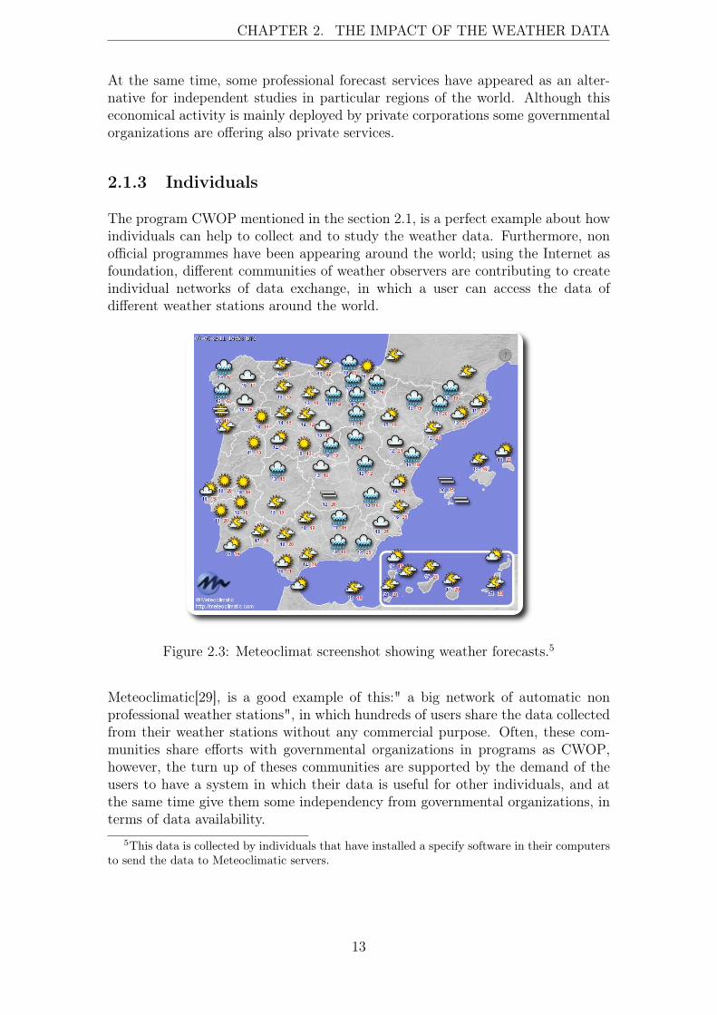
Figure 2.3: Meteoclimat screenshot showing weather forecasts.5
Meteoclimatic[29], is a good example of this:" a big network of automatic nonprofessional weather stations", in which hundreds of users share the data collectedfrom their weather stations without any commercial purpose. Often, these com-munities share efforts with governmental organizations in programs as CWOP,however, the turn up of theses communities are supported by the demand of theusers to have a system in which their data is useful for other individuals, and atthe same time give them some independency from governmental organizations, interms of data availability.
5This data is collected by individuals that have installed a specify software in their computersto send the data to Meteoclimatic servers.
13

CHAPTER 2. THE IMPACT OF THE WEATHER DATA
2.1.4 Weather data publication
The previous sections mention which organizations are involved on the processof data collection. However, the process does not end here; after the collectionand evaluation of the data, the final step is to spread and make it useful. Theimplications of the broadcasting concerning the weather forecast are multiple andthey are out of the scope of this thesis. Even so, the spreading of the data is limitedfor the protocols used in the acquisition of it. As mentioned in section 2.1.3, somecommunities of individuals appeared, taking the role of data availability disposalfor the end user. Proving this the fact that the way in which the information ismanaged by the governmental and private organizations, sometimes does not fitwith the end user’s wishes.
In the past, the weather forecast was delivered through traditional methods asnewspapers, radio and TV. Nevertheless, nowadays the Internet has taken thisrole in several aspects. Almost, all the governmental weather organizations men-tioned in this chapter have a web site in which they publish -in different quantitiesand formats-, the information collected and extracted from their meteorologicalnetworks. Although traditional media still report the daily forecast, the tendencypoints to the Internet as the future mainstream channel of this information.
In addition, other commercial web sites offer this information partially free ofcharge. This practice caused the appearance of several sites offering API servicesto fetch weather data, giving the possibility to the developers to get some storagedata to perform some operations. Due to this API availability, some organizationsnon related directly with the weather data collection workflow, have publishedsome web sites that are exposing data fetched from different APIs and providinga different range of alternatives to the users.
Figure 2.4: FMI website [23] spreading local weather observations.
The author could not find any API offering the capability to connect directly tothe weather instruments to fetch RAW data streams; all the APIs available areoffering pre-processed data.
14

CHAPTER 2. THE IMPACT OF THE WEATHER DATA
2.2 Summary
In this chapter we have given general background information in order to makethe scope of the thesis more familiar, in terms of which organizations are in chargeof the weather collection and the structure and collaboration between them. Also,it has been analyzed how different organizations of the same field coexist.
We discussed how the same activity is performed in different layers, being involvedin the process from official organizations to individuals. Some schemas have beenpresented, giving a global vision about how the weather data workflow works.
We know now that there is even a global organization named WMO. This organi-zation is only dictating some guidelines to perform the measurements. The nextchapter introduces a general overview of a weather instrument, to understand howit works, its technologies and limitations.
In the next chapter some concepts and scenarios are explained to understand how aweather instrument works, the technologies that are conforming it, and giving us aglobal vision of the technologies to have in consideration when we are implementinga protocol for a weather instrument.
15

Chapter 3
Infrastructure for the weather data
History is full of attempts to understand the weather. From the very beginning,humans have been focusing their attention in the weather, putting a lot of efforttrying to understand and predict it. The first treatise concerning weather obser-vations was Meteorologica, written by Aristotle (340 B.C.). Despite of this, "thebirth of meteorology as a genuine natural science did not take place until the inven-tion of weather instruments, such as the thermometer at the end of the sixteenthcentury, the barometer (for measuring air pressure) in 1643, and the hygrometer(for measuring humidity) in the late 1700s" [1]. It was with the invention of thetelegraph, in 1843, when the weather observations started to be useful owing tothe capability to transmit the weather reports to different locations. Since thistime elapsed, the industry has been developing and improving the weather instru-ments to achieve better measurements. Furthermore, the networks for weatherdata collection have been maturing. This chapter introduces the technology thatis composing a modern weather instrument, its role in the weather’s collection in-frastructure and shows us some concepts to understand the conflicts of this setupexposed in chapter four.
3.1 A meteorological instrument
The purpose of a weather instrument is to measure a particular phenomenon un-der certain conditions, to collect some data that can be processed to obtain someconclusions (in terms of understanding and predictability). The success of theprediction and understanding comes supported by the accuracy that these instru-ments can provide. The industry has been creating new instruments based onnew techniques discovered in Physics, to measure the phenomena; in addition, theadvance of the digital technology, is providing to the physicians a great scenario inwhich physical principles can be combined easily with digital technology, produc-ing as result modern instruments with the ability to transform the result of thesephysical principles in digital data.
Despite their size and appearance, the weather instruments are complex artifacts.The materials used to build them are a combination between plastic and metal, thiscombination provides the necessary robustness to place the weather instruments
16
CHAPTER 3. INFRASTRUCTURE FOR THE WEATHER DATA
at isolated places with all kind of degradation conditions. Furthermore, theseinstruments must have a low power consumption in order to fit the requirementsof their locations. That forces the manufacturers to use more tiny and efficienttechnologies for measuring the phenomena without sacrificing energy and accuracy.
It is not possible to discuss all these instruments in this thesis. For this reasonthe following subsections of this chapter are focused on automatic weather sta-tions(AWSes). The WMO defines an AWS as: meteorological station at which ob-servations are made and transmitted automatically [46], at the same time this con-cept comes with other nuances as Automated Weather Observing System (AWOS)and Automated Surface Observing System (ASOS): a combined system of instru-ments, interfaces and processing and transmission units is usually called an au-tomated weather observing system AWOS or automated surface observing systemASOS. It has become common practice to refer to such a system as an AWS.
The focus on the AWSes is supported by the popularity of these weather stationsas main tools to measure the weather. The author considers more useful tofocus on this technology because a wide range of AWSes is availablefor the end-non professional user; meaning this that is possible to experimentwith a new protocol using this scenario without affecting the current setups usedfor scientific purposes. In addition, later migration of the protocol to professionalinstruments should not be difficult because the manufacturers are using mostly thesame technologies in the data transmission interfaces for both brands (professionaland end-user).
3.1.1 Industrial design
Depending of the type of phenomenon to measure, the physical principle neededwill require an instrument with certain sizes, materials and lifetime. It is rarelypossible to measure multiple phenomena with the same instrument, this fact causesthe creation of instruments focused only on one phenomenon 1 and even in onlyone specify and tiny part of it.
The industrial design of an instrument is one of the keys for the success of the ob-servations; the ability to put available the required technical conditions to performthe measurement through a digital interface, reside on it. To avoid conflicts in thestudy of the phenomenon, the materials should be chosen very carefully based ona complex equation between: robustness, durability, impact, impact assessment,etc. Furthermore, the shapes and sizes depend on the environment in which theinstrument is going to be placed and the requirements needed for the physicalprinciple used.
1We refer here to high-tech and professional instruments for scientific purposes. It is possibleto find several sensors giving an output for different phenomena in one instrument. However,this is not common in the instruments used for scientist observations; at the same time this con-figuration should be considered as a weather station not as an "individual" weather instrument.
17

CHAPTER 3. INFRASTRUCTURE FOR THE WEATHER DATA
Figure 3.1: NOAA weather buoy [32], example of a complex an robustness AWS.
We can find in the market dozens of instruments for the same purpose, using insome cases the same principles to measure the phenomenon and even with somestrong differences concerning the industrial design. Though, the instruments fromdifferent manufacturers have similar dimensions and they are build with similarmaterials, there is non available standard concerning all these characteristics, onlysome general guidelines are provided by the WMO[44] suggesting dimensions andsizes for some instruments, an example of this recommendation is the following:
Wind-measuring systems can be designed in many different ways; [...] The firstsystem consists of an anemometer with a response length of 5 m, a pulse gener-ator that generates pulses at a frequency proportional to the rotation rate of theanemometer (preferably several pulses per rotation), a counting device that countsthe pulses at intervals of 0.25 s, and a microprocessor that computes averages andstandard deviation over 10 min intervals on the basis of 0.25 s samples.[46]
18

CHAPTER 3. INFRASTRUCTURE FOR THE WEATHER DATA
Figure 3.2: Generic AWS with different instruments and materials combination.
The figure 3.2 shows a generic schema in which we can see different combinationsof materials as plastic and metal, at the same time the instruments are placed indifferent heights due to technical requirements for the techniques used to performthe measurements.
Most of the instruments available at the market are the result of the coordinationbetween the requirements requested by the physicists and the possibilities that thetechnology developed by the industry. Notwithstanding, the instruments industryand their industrial design, is something really big and complex and it is out ofthe scope of the thesis. Furthermore, we need to be conscious about the industrialdesign of the instruments, because it is strong-linked to the electronics that theycan house, conditioning this the digital interfaces for data transmission that wecan install in them.
3.1.2 Electronics and data handling
The electronics of a weather instrument are barely different irrespective of thephenomenon to measure. The industry is producing a wide range of instrumentswith a complete different set of sensors. Nevertheless, as embedded systems, allthese instruments have a common need to conform these type of systems. TheWMO gives again some general guidelines with respect to electronics and weatherinstruments. The following paragraphs summarize them.
19

CHAPTER 3. INFRASTRUCTURE FOR THE WEATHER DATA
CPU
As other electronic device in charge of process data, an AWS has a Central pro-cessing unit (CPU) running at clock frequency of a few Megahertz (MHz). ThisCPU is microprocessor based with 8-bit wide.2 Despite the low bit wide of thesemicroprocessors, an AWS does not needed more calculation power because theamount of data generated by the sensors will be rarely up of 1 Kilobyte (kB),meaning this that frequencies oscillating between 8-33 MHz will fit perfectly inthe requirements to process the data.
Volatile Memory
Often 32-64 kB is the maximum amount of volatile memory available on an AWS,it makes the instrument non capable to keep too much data on a Random-accessmemory (RAM) at all. Forcing to the manufacturers to design the instrumentswith fast and reliable mass storages, ready to transfer the data from the volatilememory to the persistent storage.
Figure 3.3: Abstracted electronic schema of an AWS reading data from one sensor.
The figure ?? shows the workflow data of an abstract sensor. In the first stepthe sensor generates the data from the phenomenon, based on the observation ofsome physical principle; the data acquired is processed by the microprocessor inthe the second step, placing the data on the volatile memory. When the datais placed on RAM the in / out (IO) operations start, transferring the data fromthe volatile memory to the mass storage (persistent memory). According to theGuide to Meteorological Instruments and Methods of Observation [46] publishedby the WMO, it is highly recommended to equip the AWS with a battery backupdedicated to the volatile memory to avoid data loss due to some power fails. Thisnon common feature in generic computers can be an advantage to have in mindwhen a protocol is implemented, because it enables the possibility to have somemethodology in the protocol to recover the session after one power failure.
2Nowadays some manufacturers are introducing progressively new microprocessors using 32-bit wide.
20

CHAPTER 3. INFRASTRUCTURE FOR THE WEATHER DATA
Mass storage
Typically, an AWS, will have mass storage device to save the data collected fromthe sensors. The storage of data in the AWS has been changing in the last yearsdue to the continuously decreasing price of flash memories. It is common to findvery different architectures in terms of data storage in the AWS.
Figure 3.4: Types of storages available in an AWS.
The number of sensors and the frequency in which the information is transferredto the data centers, determines the size of available memory in an AWS. Basedon the market, the mainstream option in terms of memory size for mass storageis around 1 Megabyte (MB), that space is more than enough to save thousands ofsamples in case that the AWS has not send the data to the collecting point.
Sensors
The sensors are the digital interfaces that make an AWS different from otherembedded devices. As explained in section 1.1, a sensor is a digital interface usingsome physical principle to measure a particular phenomenon. Their principles,implementation and complexity are out of the scope of this thesis. Even so, weneed to consider the sampling frequency of them because they are involved in thefrequency in which the data is produced.
The sampling frequency of the sensor depends on the data required to understandthe phenomenon. A big range of sampling frequencies are used to measure differentphenomena. Nevertheless, the author is not assuming this frequencies as a needfor the protocol.
A correct behavior of the sensors requires a high-accurate calibration of them.The manufacturers have been developing several methodologies and mechanismsto calibrate the instruments and verify their correct behavior. These calibrations
21

CHAPTER 3. INFRASTRUCTURE FOR THE WEATHER DATA
are not considered as part of the problem statement of this thesis because they areunrelated to the methods of the data transmission.
Digital interfaces
As mentioned in the section 1.2, an AWS is equipped with at least one peripheraldevice to provide data interaction. These interfaces offer the possibility to configurethe AWS and transfer data from it. The type of device is a serial communicationphysical interface, and depending on the type and vendor of the instrument, it willbe one the following3:
• RS-232
• RS-422
• RS-485
• USB
These four types are well-known in the industry. They are available in almost allthe modern computers, however the relation of them with this thesis is focus mainlyin the bandwidth that they offer. The table 3.1 shows a comparison between thesephysical digital interfaces and their bandwidth.
Standard Bandwidth Bytes/s kBTIA/EIA-232-F[2] 116 kilobits (kbit)/s 14848 14.5 kBTIA/EIA-422-F[3] 200 kbit/s 25600 25 kBTIA/EIA-485-F[4] 35 Megabits (Mbits)/s 4587520 4.375 MBUSB[12]4 1.5 Mbits/s 196680 192 kB
Table 3.1: Comparison between standards and bandwidth offered.
Even so, as the table 3.1 shows, the minimum bandwidth provided by thesesinterfaces (RS-232) should be enough. As described in the sensors section, thetotal amount of data generated by the sensors of one AWS rarely exceeds 1kB;fitting perfectly this in the bandwidth offered by the RS-232.
Due to the constant renovation in digital interfaces that the industry does, we donot consider other old interfaces in the analysis, assuming that the protocol willwork with instruments manufactured in the last 10 years5.
Although the interfaces are not conditioning our protocol implementation, it isnecessary to highlight that most of the vendors offer the possibility to re-wire theAWS to make it work with different physical interfaces.
3Other types of interfaces can be found in the instruments. However, the industry stablished—with non-written agreement— the use of the mentioned interfaces as mainstream.
5Those should be equipped with the interfaces mentioned in the Table 3.1.
22

CHAPTER 3. INFRASTRUCTURE FOR THE WEATHER DATA
Figure 3.5: Wiring schema showing how to re-wire the AWS to use RS-422.
Datalogger
The datalogger is one the most critical parts of an AWS. It is in charge of the datalogging produced by the sensors and deliver by the operating system. Its maintask is to keep track of the data collected by the AWS. This component plays animportant role in the implementation of the protocol, because of the data of theprotocol must be originated in this part.
Depending on the architecture of the AWS, the datalogger can be an external em-bedded system with serial communication capabilities, able to send data througha network and with multi-station capability6. Small AWSes can have dataloggingcapabilities, keeping the data in a persistent memory for a short period. To havethe datalogger implemented internally implies increasing the complexity of theAWS, converting it in a more complex embedded system with features as datadelivery through a network, long-term data storage, etc.
Often, the architecture chosen for AWSes is an external device connected throughthe physical interface. These devices are equipped with some kind of connectiv-ity such as Global System for Mobile Communications (GSM), General PacketRadio Service (GPRS) or Universal Mobile Telecommunications System (UMTS)modems, using them to deliver the data to the collection point.
6Some dataloggers are able to track and to operate several AWS at the same time.
23

CHAPTER 3. INFRASTRUCTURE FOR THE WEATHER DATA
Figure 3.6: Location of the datalogger in an AWS.
3.1.3 Software
As it is common in the embedded systems, an AWS has a tiny internal software.The programming languages used to develop this software have no relevance inthis topic. We assume that the internal operating system of the AWS will offer usthe data collected from the sensors, moreover of some set of options to configureand calibrate the AWS.
We need to differentiate between the software embedded in the AWS and thesoftware at the end of the peripheral device.
AWS’s Operating System
The operating system installed in an AWS resides in a Programmable Read-OnlyMemory (PROM). Its architecture is based in a real-time clock implemented onthe mother board of the AWS. The OS provides a limited set of options to interactwith the AWS, most of these options are focused in data acquisition, calibrationand hardware configuration. This software is in charge of the formatted data ofthe AWS, in other words, it gets the data from the sensors, applies the necessary
24

CHAPTER 3. INFRASTRUCTURE FOR THE WEATHER DATA
formulas to extract a meaningful result and formats the data in one of the followingserial communication protocols7:
• RAW ASCII
• SDI-12
• NMEA-0183
After the data is formatted, it is transmitted through the peripheral device to thethe datalogger.
External software used for datalogging / data distribution
As explained in 3.1.2, an AWS needs a datalogger device to track the data collectedfrom the sensors. Irrespective of the type of datalogger, at the end of it, we willfind some computer in charge of the data manipulation and storage. The softwareinstalled on the computers can be really differently implemented and designeddepending of the vendor, but its main task is to understand the data formatchosen by the vendor to transmit information and take use of it.
The market offer concerning software for AWSes is too big, even some companiesnot related with the manufacturing of the instruments, are releasing software fordatalogging purposes. It is common that the AWS is provided from the factorywith its own set of software, nevertheless due to the serial communications proto-cols used by the AWS, is simple to implement a software that interprets and takesadvantage of the data format chosen by the vendor to implement new capabilities.
Figure 3.7: Screenshots of some popular desktop applications for AWS.
3.1.4 Networking
As mentioned in the datalogger subsection, the connectivity capabilities in anAWS resides on it. The industry offers multiple options to provide connectivityin an AWS, nevertheless, most of these options are limited for bandwidth, energy
7We need to distinguish between the data format used to communicate with the interface(ASCII, NMEA-0183, etc) and the format in which the data is formatted, this is explained thesection 4.2.
25
CHAPTER 3. INFRASTRUCTURE FOR THE WEATHER DATA
and geographical limitations. It is possible to find AWSes directly connected toa computer via USB, providing this the connectivity, or we can find an isolatedAWS in the middle of a mountain connected through a radio-link to the closestplace.
The common technologies to provide connectivity to an AWS are:
• GSM
• GPRS
• UMTS
In places with better geographical location and energy availability, it is possibleto find the following technologies offering connectivity:
• Ethernet
• USB
• 802.11b/g
Whatever the connectivity on the AWS is, the common pattern is that this con-nectivity is reliable but offers a rather low bandwidth.
3.2 Meteorological data networks
The previous section gave a general overview of AWSes, the relation betweenthem and this thesis, is how they behave in terms of networking communication,which kind of topologies are used and in which points this communication can beimproved.
To understand the workflow of the data in terms of weather data collection, weshould see an AWS as an individual node without interaction with other nodes,except the collection point.
The collection point is the place in which different data from different AWS isreceived. It is not mandatory that this collection point is the end of the weatherdata workflow, for instance it is possible to find an intermediate collection pointthat has been stablished for geographical reasons to improve the connectivity8.Even so, we consider the collection point, the place in which the data has beenreceived and it is ready to be processed.
8Some AWS are located at inaccessible places, sometimes this implies to establish a collectionpoint close to them to avoid issues such as lack of connectivity (GSM, GPRS, UMTS).
26
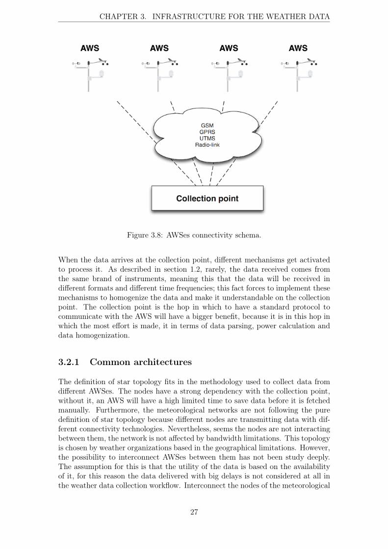
CHAPTER 3. INFRASTRUCTURE FOR THE WEATHER DATA
Figure 3.8: AWSes connectivity schema.
When the data arrives at the collection point, different mechanisms get activatedto process it. As described in section 1.2, rarely, the data received comes fromthe same brand of instruments, meaning this that the data will be received indifferent formats and different time frequencies; this fact forces to implement thesemechanisms to homogenize the data and make it understandable on the collectionpoint. The collection point is the hop in which to have a standard protocol tocommunicate with the AWS will have a bigger benefit, because it is in this hop inwhich the most effort is made, it in terms of data parsing, power calculation anddata homogenization.
3.2.1 Common architectures
The definition of star topology fits in the methodology used to collect data fromdifferent AWSes. The nodes have a strong dependency with the collection point,without it, an AWS will have a high limited time to save data before it is fetchedmanually. Furthermore, the meteorological networks are not following the puredefinition of star topology because different nodes are transmitting data with dif-ferent connectivity technologies. Nevertheless, seems the nodes are not interactingbetween them, the network is not affected by bandwidth limitations. This topologyis chosen by weather organizations based in the geographical limitations. However,the possibility to interconnect AWSes between them has not been study deeply.The assumption for this is that the utility of the data is based on the availabilityof it, for this reason the data delivered with big delays is not considered at all inthe weather data collection workflow. Interconnect the nodes of the meteorological
27
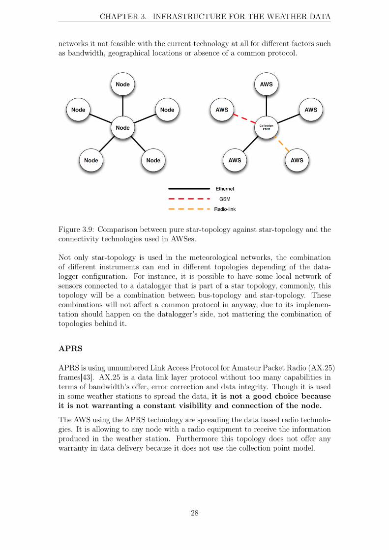
CHAPTER 3. INFRASTRUCTURE FOR THE WEATHER DATA
networks it not feasible with the current technology at all for different factors suchas bandwidth, geographical locations or absence of a common protocol.
Figure 3.9: Comparison between pure star-topology against star-topology and theconnectivity technologies used in AWSes.
Not only star-topology is used in the meteorological networks, the combinationof different instruments can end in different topologies depending of the data-logger configuration. For instance, it is possible to have some local network ofsensors connected to a datalogger that is part of a star topology, commonly, thistopology will be a combination between bus-topology and star-topology. Thesecombinations will not affect a common protocol in anyway, due to its implemen-tation should happen on the datalogger’s side, not mattering the combination oftopologies behind it.
APRS
APRS is using unnumbered Link Access Protocol for Amateur Packet Radio (AX.25)frames[43]. AX.25 is a data link layer protocol without too many capabilities interms of bandwidth’s offer, error correction and data integrity. Though it is usedin some weather stations to spread the data, it is not a good choice becauseit is not warranting a constant visibility and connection of the node.
The AWS using the APRS technology are spreading the data based radio technolo-gies. It is allowing to any node with a radio equipment to receive the informationproduced in the weather station. Furthermore this topology does not offer anywarranty in data delivery because it does not use the collection point model.
28
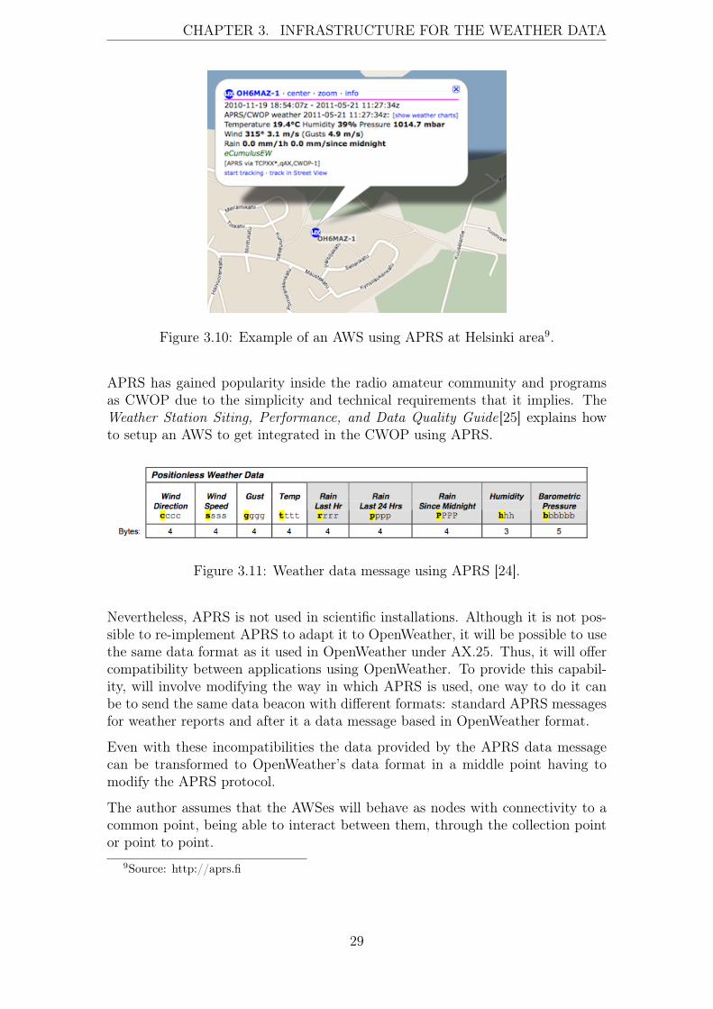
CHAPTER 3. INFRASTRUCTURE FOR THE WEATHER DATA
Figure 3.10: Example of an AWS using APRS at Helsinki area9.
APRS has gained popularity inside the radio amateur community and programsas CWOP due to the simplicity and technical requirements that it implies. TheWeather Station Siting, Performance, and Data Quality Guide[25] explains howto setup an AWS to get integrated in the CWOP using APRS.
Figure 3.11: Weather data message using APRS [24].
Nevertheless, APRS is not used in scientific installations. Although it is not pos-sible to re-implement APRS to adapt it to OpenWeather, it will be possible to usethe same data format as it used in OpenWeather under AX.25. Thus, it will offercompatibility between applications using OpenWeather. To provide this capabil-ity, will involve modifying the way in which APRS is used, one way to do it canbe to send the same data beacon with different formats: standard APRS messagesfor weather reports and after it a data message based in OpenWeather format.
Even with these incompatibilities the data provided by the APRS data messagecan be transformed to OpenWeather’s data format in a middle point having tomodify the APRS protocol.
The author assumes that the AWSes will behave as nodes with connectivity to acommon point, being able to interact between them, through the collection pointor point to point.
9Source: http://aprs.fi
29
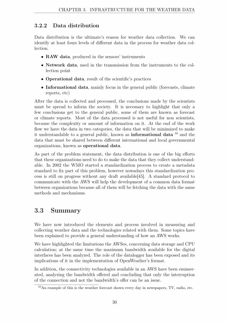
CHAPTER 3. INFRASTRUCTURE FOR THE WEATHER DATA
3.2.2 Data distribution
Data distribution is the ultimate’s reason for weather data collection. We canidentify at least fours levels of different data in the process for weather data col-lection.
• RAW data, produced in the sensors’ instruments
• Network data, used in the transmission from the instruments to the col-lection point
• Operational data, result of the scientific’s practices
• Informational data, mainly focus in the general public (forecasts, climatereports, etc)
After the data is collected and processed, the conclusions made by the scientistsmust be spread to inform the society. It is necessary to highlight that only afew conclusions get to the general public, some of them are known as forecastor climate reports. Most of the data processed is not useful for non scientists,because the complexity or amount of information on it. At the end of the workflow we have the data in two categories, the data that will be minimized to makeit understandable to a general public, known as informational data 10 and thedata that must be shared between different international and local governmentalorganizations, known as operational data.
As part of the problem statement, the data distribution is one of the big effortsthat these organizations need to do to make the data that they collect understand-able. In 2002 the WMO started a standardization process to create a metadatastandard to fix part of this problem, however nowadays this standardization pro-cess is still on progress without any draft available[45]. A standard protocol tocommunicate with the AWS will help the development of a common data formatbetween organizations because all of them will be fetching the data with the samemethods and mechanisms.
3.3 Summary
We have now introduced the elements and process involved in measuring andcollecting weather data and the technologies related with them. Some topics havebeen explained to provide a general understanding of how an AWS works.
We have highlighted the limitations the AWSes, concerning data storage and CPUcalculation; at the same time the maximum bandwidth available for the digitalinterfaces has been analyzed. The role of the datalogger has been exposed and itsimplications of it in the implementation of OpenWeather’s format.
In addition, the connectivity technologies available in an AWS have been enumer-ated, analyzing the bandwidth offered and concluding that only the interruptionof the connection and not the bandwidth’s offer can be an issue.
10An example of this is the weather forecast shown every day in newspapers, TV, radio, etc.
30

CHAPTER 3. INFRASTRUCTURE FOR THE WEATHER DATA
Finally, the topologies used in the meteorological networks haven analyzed briefly,clarifying that the AWS are behaving as nodes without interaction between them,only sending data to a common point named "collection point" (the node thatinteracts with all the AWSes). The APRS protocol and its topology have beenexplained, taking in consideration the possibility to be compatible with the imple-mentation of OpenWeather.
The next chapter describes the technical issues related with the data transmissionin the AWSes.
31

Chapter 4
State of the art in the weather datatransmission
The previous chapters we have introduced a general overview of the basics neededto understand how weather data are collected and how a weather instrument isdesigned to undertake its function. Even though the purpose of this thesis is toanalyze the issues found in the weather data transmission and to provide an alter-native to fix these problems. Nowadays, the way in which a weather instrument istransmitting the data can be classified as generic, because the methodologies usedin this task have not been optimized thinking in the data implied in the process.This practice limits the possibility to acquire data without the implementationof intermediary hops in which the data is parsed and converted to a useful dataformat. This results in an unnecessary investment of CPU cycles, delays in thedata delivery, incompatibility between difference brand of instruments, and at theend causing the investment of more resources and effort to exchange data betweenorganizations. This chapter analyzes the technical points that are causing thisissues in the weather data transmission.
4.1 The evolution of the digital interfaces in aweather instrument
As mentioned in chapter three, the meteorology did not advance until the inven-tion of the telegraph. The value of the weather data resides in the ability tocombine it with other sources to get some conclusions to make predictions. Nev-ertheless, this combination involves having the possibility to transmit this datafast and far enough. The telegraph brought this possibility, and with this newchance scientists had the opportunity to understand concepts as wind flow andstorm movement[1] among others. During the 19th and 20th century the industryhas been developing new improvements in the instruments manufactured; all ofthese improvements come supported for the new methods found by the physics tomeasure the phenomena, and the conversion of them to digital instruments.
In 1969 the RS-232-C standard was published; this interface has been the main-
32

CHAPTER 4. STATE OF THE ART IN THE WEATHER DATATRANSMISSION
stream technology used in the weather instruments for more than thirty years;only in the last decade some updates have been introduced in the industry, mi-grating to new standards as ANSI/EIA/TIA-232-F[2], ANSI/EIA/TIA-422-F[3],ANSI/EIA/TIA-485-F[4] or USB.
As far as we can judge this slow transition in as of the digital interfaces used ina weather instrument come supported for the fact of the wide use of RS-232-Cin different fields of the industry, at the same time these interfaces fit perfectlyin the needs of the weather data transmission: enough bandwidth, low cost andthey are an international standard. If some updates have been introduced in theindustry of the weather’s instruments, they come supported by the need to adaptthese interfaces to the hardware ports available at the moderns computers, seldomby the requirement of more bandwidth1.
It is an observable fact that the industry performs some updates in the technologyto make it compatible with the moderns computers despite that the is not needed interms of data delivery. Moreover, the new standards are offering more capabilitiesa part of more bandwidth, for example, technologies as USB, bring the opportunityto plug an AWS to a computer and have it working without previous configurationsas bit-rate, parity, etc.2
These interfaces provided by the industry are generic as in other technologies, notmattering the type of data transmitted through them; a well-known process ofstandardization has been performed to develop these interfaces. Though does notexist any standard specifying which type of interface should provide an AWS, theWMO recognizes the universality of the interfaces mentioned, and establishes themas requirement for the AWSes performing official measurements for governmentalorganizations[46]. Based on this we assume that a protocol implemented in anAWS must work under these technologies; because these interfaces are generic,they have not any requirement for the data transmitted, giving complete freedomto us to implement any protocol over them.
As mentioned in section 3.1.2, the bandwidth offered for the different interfacesavailable in a weather instrument, are offering even more bandwidth than theamount of data that an AWS’s CPU can process. Hence, a weather instrument hasnot limitations (concerning bandwidth) in the data interfaces that would preventthe possibility to implement a protocol to afford the needs of the data delivery.
Based on this retrospective we assume that the digital interfaces provided by theindustry are well know and tested standards, providing mechanisms to achievethe goal of the data transmission. However, as it is explained in section 4.2 noweather data transmission protocol has been defined for them. We identified thisas the first deficiency in the weather data transmission because of thepotential offered by these digital interfaces is not used in the weatherinstruments.
1In some big AWSes in which have been placed many sensors and complex instruments, existsthe possibility to need a bigger bandwidth, even so this is a specific case out of the mainstreamsetups.
2Interfaces based in ANSI/EIA/TIA-232-F, ANSI/EIA/TIA-422-F, ANSI/EIA/TIA-485-Frequire to adapt the software to certain bit-rates, flow controls and other parameters.
33

CHAPTER 4. STATE OF THE ART IN THE WEATHER DATATRANSMISSION
4.2 The absence of a protocol
The goal of the Internet Engineering Task Force (IETF)[26] is to make the Internetwork better. One of its multiple task implies to take care about the standardizationprocess of the new Internet standards. A protocol is considered as standard whenthe IETF publishes a memorandum3, specifying all the aspects of the protocol andassigning a number in the STD series of it[7].
A research performed by the author in the RFCs available at IETF’s website [26]4,looking for the following terms: "weather", "meteorology", "weather station","atmosphere", "weather data", gave as result the following number of mentions.Only 9 RFCs do direct or indirect mention to the weather data.
The first RFC mentioning a protocol related with the weather data is the RFC765 [38] File Transfer Protocol (FTP):
3.4.2. BLOCK MODE The file is transmitted as a series of data blocks preceded byone or more header bytes. The header bytes contain a count field, and descriptorcode. The count field indicates the total length of the data block in bytes, thusmarking the beginning of the next data block (there are no filler bits). The descrip-tor code defines: last block in the file (EOF) last block in the record (EOR), restartmarker (see the Section on Error Recovery and Restart) or suspect data (i.e., thedata being transferred is suspected of errors and is not reliable). This last code isNOT intended for error control within FTP. It is motivated by the desire of sitesexchanging certain types of data (e.g., seismic or weather data) to send and re-ceive all the data despite local errors (such as "magnetic tape read errors"), but toindicate in the transmission that certain portions are suspect). Record structuresare allowed in this mode, and any representation type may be used.
Nevertheless, this reference of weather data is just an example (as the other refer-ences) that disappeared in later updates of the File Transfer Protocol (FTP).
The industry has focused its effort in improving the measure methodologies, therobustness of the instruments or other features as power consumption or life-time.Thus, the methodologies utilized to transmit weather data have been developedindependently by the vendors, choosing their own data formats and techniques.
Nevertheless, the WMO initialized different programs as Global Observing System(GOS), Global Telecommunication System and WMO Information System (GTS), Global Data-processing and Forecasting System (GDPFS) [44] among others, inwhich the weather data exchange is a key-component of the systems to archive thegoals of these programs. In addition, as mentioned in the section 3.2.2 the WMOstarted a process of standardization 9 years ago.
Even assuming that the industry focused its attention on prioritizing measure-ments methods and product quality, the technologies related to the weather datatransmission are outdated. The proof of this is that only a few governmental orga-
3This memorandums are named as Request for Comments (RFC) for historical reasons.4The searched has been performed over all the content of the RFC published: ftp://ftp.rfc-
editor.org/in-notes/tar/RFC-all.tar.gz . Retrieved: 28-03-2011.
34

CHAPTER 4. STATE OF THE ART IN THE WEATHER DATATRANSMISSION
nizations have access to real-time information 5 collected from the AWSes6, at thesame time programs as CWOP still depend of technologies such as FTP or APRS,that they do not contemplate scenarios in which scalability, data on demand orreal-time data is needed. Finally, as a real example, the SMEAR project[40] isexperimenting the issues of not having a standard protocol for the AWS, produc-ing as result the implementation of intermediary points to parse and normalize thedata, incompatibility between different sources of data from the same phenomenoncollected with different instruments and scalability of the system among others.
Based in these facts, we can say that during the last 40 years the industry unat-tended the communication’s side of the AWS, adapting the instruments to becapable to use protocols as FTP to transmit the data from the AWS to the col-lection point; focalizing the effort transmiting the data not mattering at all thetechnologies used or if they are or not optimized for that purpose. This prac-tice gave as result multiple data formats implemented by the vendors without anycommon agreement, creating a huge incompatibility between the instruments andseveral bottlenecks in the data transmissions.
The following subsections expose some data format used by the vendors to archivethe data transmission and analyze why these data formats are causing bottlenecks.
Data formats used by the vendors
As mentioned in previous chapters, the format in which the data is produced byAWS is formatted is up to the vendors. Nowadays the only standards used orinvolved in this process is ASCII as character-encoding scheme or NMEA-0183.Depending on the digital interface different control characters can be used, forinstance is a common practice to generate one line of data follow by the carriagereturn (CR) or carriage return followed by line feed (CR+LF)7.
>"BARDATA"<LF>«LF><CR>"OK"<LF><CR><"BAR 29775"<LF><CR><"ELEVATION 27"<LF><CR><"DEW POINT 56"<LF><CR><"VIRTUAL TEMP 63"<LF><CR><"C 29"<LF><CR> <"R 1001"<LF><CR><"BARCAL 0"<LF><CR> <"GAIN 1533"<LF><CR><"OFFSET 18110"<LF><CR>
Table 4.1: Example of data format used in a specific AWS to communicate thebarometric pressure.
Depending the AWS’s brand the data’s format is completely different from otherbrands and vendors. In most of the cases the data format is implemented based
5All of these instruments are generating by default real-time data.6Note that these organizations can have this capability due to they invest a big effort in to
develop custom systems for their weather instrument’s setup.7CR hexadecimal value: 0x0D. LF hexadecimal value: 0x0A. CR+LF: hexadecimal value
0x0D 0x0A.
35

CHAPTER 4. STATE OF THE ART IN THE WEATHER DATATRANSMISSION
in the vendor’s wishes. These wishes can be supported by technical reasons ornot. Some vendors used acronyms to refer the data values returned by the sensors,others use the whole word to refer the phenomenon; not mattering the techniqueused in the data format, is a fact that they do not exist any compatibility offormats between vendors.
0r2,Ta=10.6C,Tp=10.8C,Ua=74.6P,Pa=1006.0HKHK
Table 4.2: Another example of data format used in a specific AWS to communicatedifferent data as temperature or barometric pressure.
A part of these big differences between the formats used in the digital interfaces, isneeded to highlight that also the field’s value used in CSV or TSV files productedby the AWS are unique and incompatible between vendors. Thus, two levels ofincompatibility exist, first the original data is delivered in a custom formatteduntill the software’s side. In the software’s side this data is converted to a CSV orTSV format with the custom fields chosen by the vendors; this causes that evenhaving the final data in a standard format as CSV or TSV, the order of the fieldsand their denomination will be different, forcing to the scientist to add an extralayer to the workflow to normalize this data and make it ready to be combined.
Data formats used by governmental organizations
Despite the fact that vendors used privative and non standard formats for thedata, the WMO has defined some specific data representation for certain users.An example of this is the Meteorological Service For International Air Navigation(METAR) format. Approved by the International Civil Aviation Organization(ICAO), this format is the only one considered as official to communicate weatherforecasting to the aviation and at the same it is widely use for other purposes asgeneral weather forecasting.
Phenomenon METAR’s acronymcumulonimbus clouds CBthunderstorm TSmoderate or severe turbulence MOD TURB, SEV TURBwind shear WShail GR
Table 4.3: Some acronyms used in METAR format [36].
However, this format has not relationship with the formats used by the vendors.Only a few AWSes have the ability to product the METAR format by default. TheAWS doing this are only focus in product data useful for the aviation, wasting theopportunity to provide the data in other formats for different use.
36

CHAPTER 4. STATE OF THE ART IN THE WEATHER DATATRANSMISSION
Figure 4.1: Weather data workflow, normal AWS VS METAR’s AWS.
METAR format is just an example of the multiple data formats invented for aspecific purpose. The point to highlight is that often the weather data can berepresented in a complete different format compare with the original format usedfor it. Nevertheless, the optimization of the data format until the point in whichit is transformed marks a big difference in terms of data manipulation.
With the current technology the weather data arrives in different formats andwith difference times frequencies, forcing to implement customized and particularmechanisms to transform this data to the format required. The complexity ofthis task resides in the requirement de facto requested by the AWSes: they needintermediary points to convert the data because by default the data provided isuseless for the required result.
In conclusion, it does not matter if the vendors provide a well known documenteddata format of their instruments. Because the observation of the weather is per-formed with different instruments, the data must be normalized to make it un-derstandable. Thus, at the end of the data workflow (when we take data fromdifferent sources and instruments), an intermediary layer to translate the vendor’sdata format to a common format is required.
Mainstream architecture used for the weather data transmission
To understand where are located the bottlenecks in the weather data transmissionsis needed to understand the current architecture used by the vendors to archivethis goal. As explained in section 3.1.2, an AWS is an embedded system collectinginformation produced by the sensors attached to it. As embedded system, it hassmall capabilities to perform big CPU calculations, massive data storage or datadelivery, however moderns systems are pretty balanced in terms of hardware andsoftware to archive this goal. Although the AWS have been optimized to collectand delivery the data, the protocols used for it are generic an non-specific. As
37

CHAPTER 4. STATE OF THE ART IN THE WEATHER DATATRANSMISSION
explained in previous chapters the quality of the weather predictions reside in theability to collect and process the atmosphere data with efficiency, reliability andfast delivery.
Despite of this, the methodologies for network communications are not optimizedfor this purpose. The following figure shows how the data is delivery.
Figure 4.2: Example of an AWS transmitting weather data.
In the figure 4.2 we can appreciate an example of the methodology used to trans-mit the weather data. In the hardware’s level the data is delivered through adigital interface as explained in section 3.1.2, using some custom vendor’s dataformat, commonly based in abbreviations as "Tmp (Temperature)", "Bp (Baro-metric Pressure )" "Ws (Wind Speed)", among others. These abbreviations areunderstood by the software. Depending of the AWS’s setup this process can hap-pen all together between the AWS and the datalogger:
Figure 4.3: Example of a AWS and a datalogger transmitting weather data.
If the AWS / datalogger has not network capabilities, a third entity can enter inthe workflow. This entity is commonly a modern computer with the peripheraldevices needed to interact with the AWS. The computer takes the role of theweather data transmission, due to the possibilities that it offers, one computer canmanage several AWSes at the same time. Nevertheless, it does not introduce newprotocols to send the data, it stills using protocols as FTP or in some setups justshared folders using Server Message Block (SMB):
38
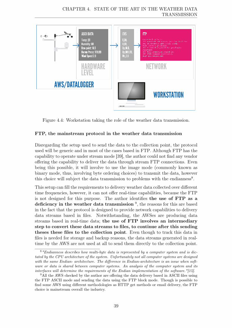
CHAPTER 4. STATE OF THE ART IN THE WEATHER DATATRANSMISSION
Figure 4.4: Workstation taking the role of the weather data transmission.
FTP, the mainstream protocol in the weather data transmission
Disregarding the setup used to send the data to the collection point, the protocolused will be generic and in most of the cases based in FTP. Although FTP has thecapability to operate under stream mode [39], the author could not find any vendoroffering the capability to deliver the data through stream FTP connections. Evenbeing this possible, it will involve to use the image mode (commonly known asbinary mode, thus, involving byte ordering choices) to transmit the data, howeverthis choice will subject the data transmission to problems with the endianness8.
This setup can fill the requirements to delivery weather data collected over differenttime frequencies, however, it can not offer real-time capabilities, because the FTPis not designed for this purpose. The author identifies the use of FTP as adeficiency in the weather data transmission 9, the reasons for this are basedin the fact that the protocol is designed to provide network capabilities to deliverydata streams based in files. Notwithstanding, the AWSes are producing datastreams based in real-time data; the use of FTP involves an intermediarystep to convert these data streams to files, to continue after this sendingtheses these files to the collection point. Even though to track this data infiles is needed for storage and backup reasons, the data streams generated in real-time by the AWS are not used at all to send them directly to the collection point.
8"Endianness describes how multi-byte data is represented by a computer system and is dic-tated by the CPU architecture of the system. Unfortunately not all computer systems are designedwith the same Endian- architecture. The difference in Endian-architecture is an issue when soft-ware or data is shared between computer systems. An analysis of the computer system and itsinterfaces will determine the requirements of the Endian implementation of the software."[15].
9All the AWS checked by the author are offering the data delivery based in ASCII files usingthe FTP ASCII mode and sending the data using the FTP block mode. Though is possible tofind some AWS using different methodologies as HTTP get methods or email delivery, the FTPchoice is mainstream overall the industry.
39

CHAPTER 4. STATE OF THE ART IN THE WEATHER DATATRANSMISSION
In addition, the use of this methodology is forcing extra IO operations required bythe FTP, that are not required in other protocols in which the data transfer doesnot involve the use of files.
Thus, it is not available any protocol taking advantage of all the capabilities offeredby the AWSes and its sensors, instead generic protocols as FTP or SMB havebeen chosen to transmit data. These protocols are widely and accepted as themainstream solutions for data transmission available on the weather instruments.
4.3 The missing standard
One of the important factors of an implemented protocol, is to know how is goingto be represented the data transmitted at the end of the transmission. This helpsto design the best representation required by the data; for instance a protocolimplementing real-time capabilities should be focus in fast data delivery and dataintegrity, among others.
In addition, to know the final representation of the data helps to implement aprotocol optimized for the data that is transporting, this gives as result a bettersoftware for the protocol, besides it provides the capability to implement differentprotocols giving the same data result10.
Nevertheless, the weather data has certain particularities; the WMO defines a setof methods to perform different measurements, notwithstanding theses methodsare changing based in the advance of the physics, and these changes are causingan instability concerning what is the best way to measure a phenomenon, thusthe data representation can get affected easily. Furthermore, the correlation be-tween phenomena generates certain scenarios in which the data results can changecompletely if a new method is found to measure the phenomenon. This fact de-termines to which point we can have or not standards for these particular data.The WMO defines which system of units must be used to represent the data forscientific purposes, in addition several guidelines are provided by the WMO toperform the measurements under standard procedures. However, these guidelinesare not enough to specify the final format of the data.
The WMO started a process of standardization in 2002, the goal is to create a dataformat to fit the requirements of the GOS, in other words to provide a commonbasement to represent the data of the weather’s observations. This is an arduoustask, not only for the amount of data that is needed to manage, also for the big amount of different phenomena in the atmosphere that are producing different dataand their particularities. It is expected that in some point, the WMO will publisha standard for weather’s metadata representation, nevertheless, after 9 years thisprocess still under development.
The absence of a standard for weather data representation is one of the key-issuesof the current situation. Without knowing how must be formatted the data at the
10A good example of this are the peer to peer networks, in which the protocol’s designers knowthat at end of the process the data must be a file.
40
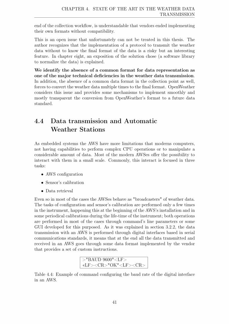
CHAPTER 4. STATE OF THE ART IN THE WEATHER DATATRANSMISSION
end of the collection workflow, is understandable that vendors ended implementingtheir own formats without compatibility.
This is an open issue that unfortunately can not be treated in this thesis. Theauthor recognizes that the implementation of a protocol to transmit the weatherdata without to know the final format of the data is a risky but an interestingfeature. In chapter eight, an exposition of the solution chose (a software libraryto normalize the data) is explained.
We identify the absence of a common format for data representation asone of the major technical deficiencies in the weather data transmission.In addition, the absence of a common data format in the collection point as well,forces to convert the weather data multiple times to the final format. OpenWeatherconsiders this issue and provides some mechanisms to implement smoothly andmostly transparent the conversion from OpenWeather’s format to a future datastandard.
4.4 Data transmission and AutomaticWeather Stations
As embedded systems the AWS have more limitations that moderns computers,not having capabilities to perform complex CPU operations or to manipulate aconsiderable amount of data. Most of the modern AWSes offer the possibility tointeract with them in a small scale. Commonly, this interact is focused in threetasks:
• AWS configuration
• Sensor’s calibration
• Data retrieval
Even so in most of the cases the AWSes behave as "broadcasters" of weather data.The tasks of configuration and sensor’s calibration are performed only a few timesin the instrument, happening this at the beginning of the AWS’s installation and insome periodical calibrations during the life-time of the instrument; both operationsare performed in most of the cases through command’s line parameters or someGUI developed for this purposed. As it was explained in section 3.2.2, the datatransmission with an AWS is performed through digital interfaces based in serialcommunications standards, it means that at the end all the data transmitted andreceived in an AWS goes through some data format implemented by the vendorthat provides a set of custom instructions.
>"BAUD 9600"<LF>«LF><CR>"OK"<LF><CR>
Table 4.4: Example of command configuring the baud rate of the digital interfacein an AWS.
41
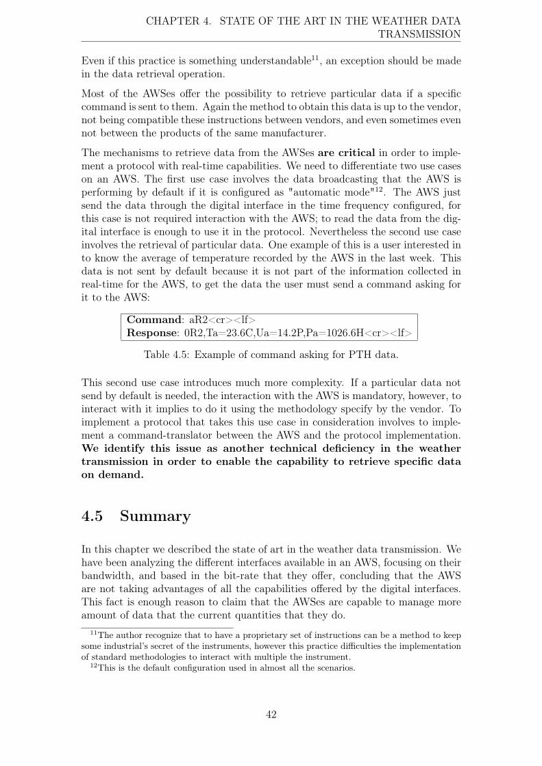
CHAPTER 4. STATE OF THE ART IN THE WEATHER DATATRANSMISSION
Even if this practice is something understandable11, an exception should be madein the data retrieval operation.
Most of the AWSes offer the possibility to retrieve particular data if a specificcommand is sent to them. Again the method to obtain this data is up to the vendor,not being compatible these instructions between vendors, and even sometimes evennot between the products of the same manufacturer.
The mechanisms to retrieve data from the AWSes are critical in order to imple-ment a protocol with real-time capabilities. We need to differentiate two use caseson an AWS. The first use case involves the data broadcasting that the AWS isperforming by default if it is configured as "automatic mode"12. The AWS justsend the data through the digital interface in the time frequency configured, forthis case is not required interaction with the AWS; to read the data from the dig-ital interface is enough to use it in the protocol. Nevertheless the second use caseinvolves the retrieval of particular data. One example of this is a user interested into know the average of temperature recorded by the AWS in the last week. Thisdata is not sent by default because it is not part of the information collected inreal-time for the AWS, to get the data the user must send a command asking forit to the AWS:
Command: aR2<cr><lf>Response: 0R2,Ta=23.6C,Ua=14.2P,Pa=1026.6H<cr><lf>
Table 4.5: Example of command asking for PTH data.
This second use case introduces much more complexity. If a particular data notsend by default is needed, the interaction with the AWS is mandatory, however, tointeract with it implies to do it using the methodology specify by the vendor. Toimplement a protocol that takes this use case in consideration involves to imple-ment a command-translator between the AWS and the protocol implementation.We identify this issue as another technical deficiency in the weathertransmission in order to enable the capability to retrieve specific dataon demand.
4.5 Summary
In this chapter we described the state of art in the weather data transmission. Wehave been analyzing the different interfaces available in an AWS, focusing on theirbandwidth, and based in the bit-rate that they offer, concluding that the AWSare not taking advantages of all the capabilities offered by the digital interfaces.This fact is enough reason to claim that the AWSes are capable to manage moreamount of data that the current quantities that they do.
11The author recognize that to have a proprietary set of instructions can be a method to keepsome industrial’s secret of the instruments, however this practice difficulties the implementationof standard methodologies to interact with multiple the instrument.
12This is the default configuration used in almost all the scenarios.
42

CHAPTER 4. STATE OF THE ART IN THE WEATHER DATATRANSMISSION
Data formats used by the vendors and data format requested for the governmentalorganizations have been compared; finding that is not any relation between theoriginal format used in the AWSs and the final format in which the weather datais represented, being this one of the reasons that forces the implementation ofintermediary points to translate the data to different data formats.
The absence of a protocol dedicated to the weather data transmission has beenstudied; the use of the FTP has been explained and the limitations that it caninvolve to transmit data in real-time have been analyzed. We conclude that FTPis chose by the industry as non-optimal solution that fix partially the issue of theweather data transmission. In addition, the key issues of FTP has been exposed inorder to implement a system that use this protocol to delivery data in real-time.
We analyzed the implications of a missing standard to represent the weather data,concluding that without a consensus of the international community about howthe weather data should be represented, is really complex to implement a protocolto fit all the requirements needed.
Despite the absence of a protocol and the use of multiple protocols and data for-mats, the industry and weather organizations are using these methodologies to ac-quire weather data in their weather data networks. Although projects such as GOSor GDPFS, are looking for technologies to optimize and standardize the weatherdata transmission, the current status of weather data acquisition is based on themethodologies that the industry provided without previous agreement. Thesemethodologies have been accepted by the weather organizations as the standardsfor the weather data transmission, achieving until today their purpose.
At the end of the chapter we exposed how to retrieve particular data from the AWSinvolves user interaction, adding complexity to the data workflow and requiringan intermediary step to translate the data requests to the native format used inthe AWS to retrieve the data. We identify this as an impediment in order toimplement a protocol that provides data on demand.
The next chapter explains in which consists OpenWeather, its architecture andhow it can fix the issues explained in this chapter.
43

Chapter 5
Introduction to OpenWeather
The previous chapter summarized the issues found by the author in the protocolsused for weather data. It has been analyzed how the weather instruments useprotocols as FTP or SMB to transmit data. Nevertheless, these protocols are notdesigned to be used in a scenario in which the data is generated based on real-timeinputs. In addition, the current methodologies provided by the industry, are notefficient enough to interact with the AWS without additional effort in performingdata normalization or data delivery. This chapter gives a general overview ofOpenWeather, the protocol developed by the author, in order to provide a solutionto problems that weather instruments encounter during data transmission.
5.1 Overview and goals
OpenWeather is an application layer protocol based on TCP/Internet Protocol(IP). It assumes a reliable transport layer (TCP), in order to achieve a successfuldata delivery, based on such mechanisms as error detection, flow control, congestioncontrol, etc.
The protocol is built assuming three principles:
• Every AWS is considered to be a node
• A node accepts incoming sessions from peering hosts and initiates outgoingsessions to peering hosts as well
• An AWS must have the capability to provide and to request services fromother nodes.
These principles are supported by assumptions that an AWS is an embedded sys-tem with networking capabilities, able to interact via TCP/IP to deliver the dataproduced by its sensors. The sensors’ output are considered to be services offeredby the AWS (node) to other nodes.
In addition, the star topology explained in section 3.1.4, disappears to give way toa decentralized topology based on a peer to peer architecture.
44

CHAPTER 5. INTRODUCTION TO OPENWEATHER
OpenWeather provides the capability to dispense a unique collection point. In-stead, all nodes can be collection point and at the same time to be part of othercollections points. In addition, the protocol offers a service oriented model (SOA),to provide an easy way to interact with the nodes and retrieve or send data tothem.
Figure 5.1: Comparison of the currently centralized architecture provided by theindustry against OpenWeather architecture.
From the perspective of portability and data delivery, the protocol has been de-signed to avoid problems with the endianness and data normalization; to achievethis goal, JSON[16] has been chosen as data interchange format between nodes.
JSON allows OpenWeather to use data streams based on parsable objects, facil-itating the data manipulation and normalizing the data to one common format.Additionally, JSON is well supported by several libraries[17], bringing the possi-bility to easily create applications based on OpenWeather format.
45

CHAPTER 5. INTRODUCTION TO OPENWEATHER
Figure 5.2: Example of a OpenWeather’s JSON object inside of data message.
5.1.1 Improvements in the current technology
OpenWeather provides a new paradigm for weather data collection. Based on aPeer to peer (P2P) architecture, it allows the users to interact between multiplenodes, retrieving and sending information inside of the network independentlyof the brand’s instruments used. At the same time, it brings the possibility tocombine the real-time data streams obtained from the nodes, providing a stack tobuild applications using multiple data sources without requiring extra resourceson the data manipulation.
In addition, the protocol is designed to be extensible, adaptable to new typesof data, while maintaining compatibility with future formats. Furthermore, theservice oriented model (SOA) of the nodes, allows the users to develop applicationsthat only want to obtain some specific data from a particular service.
Finally, the protocol brings new opportunities to be operated under distributedmodels and to provide implementational basis for future standards of the weatherdata categorization. Because the data interchange format is text-based and human-readable, it provides the capability to combine the protocol with database appli-cations without the need to develop extra APIs, facilitating even more possibilitiesto take advantage of the data.
5.1.2 The role of OpenWeather and data spreading
OpenWeather is designed to fix deficiencies in weather data transmission, whilehelping with the tasks of spreading data to the end users. Though most of thephenomena require scientific analysis to make the data understandable, some phe-nomena as atmospheric temperature, pressure or wind speed, are simple enoughand known to be spread across them directly to the end users without the needof additional processing. OpenWeather allows to connect to an AWS1, to retrievethis type of data in real-time and —host to host— based, not needing more than
1Through a intermediary layer implemented through software.
46

CHAPTER 5. INTRODUCTION TO OPENWEATHER
a computer with software supporting the OpenWeather protocol and network con-nectivity.
In addition, the technologies used in OpenWeather can facilitate the creation ofnew APIs for web services oriented on weather’s forecasts. Some websites offer thepossibility for calling APIs to obtain weather data. However, these API calls arecompletely different between websites, which leads with extra development timeof web applications which utilizes different web resources for data extraction. Thisproblem can be easily handled with OpenWeather, creating standard API callsaccording to the protocol specification. This enables the use of such encapsulatedprotocols methods as HTTP for creating for an intermediary bridge between theweb application and the end nodes.
Figure 5.3: Example of an API call through HTTP and OpenWeather.
5.1.3 Contribution to the current methodologies for weatherdata acquistion
Even if OpenWeather is a proof of concept of an adapted protocol for AWS, itproves how the problems exposed in chapter four can be resolved. The feasibilityof migration of scientific installations for production, will be deemed feasible asthe principles applied in OpenWeather, just adopting the P2P architecture or theuse of a human-readable lightweight format as JSON, it will be enough to observeimprovements in data delivery and acquisition. In chapter seven is analyzed theresults of use OpenWeather.
As it was mentioned in chapter four, the WMO has several worldwide projects, suchas GOS, in which different weather organizations around the world are involved inthe process of creation of future basis for weather data processing. As describedon WMO’s website[44], one of the purposes of the project is: ’The coordinatedsystem of methods and facilities for making meteorological and other environmentalobservations on a global scale in support of all WMO Programmes”. OpenWeather,as scalable and extensible protocol, can proven useful in certain areas of projectsas GOS or SMEAR[40], concerning data availability.
5.1.4 Impact on weather instrument industry
As it was analyzed in chapter four, the industry has not started the process ofstandardization for their instruments. Despite the issues that this practice causes,
47
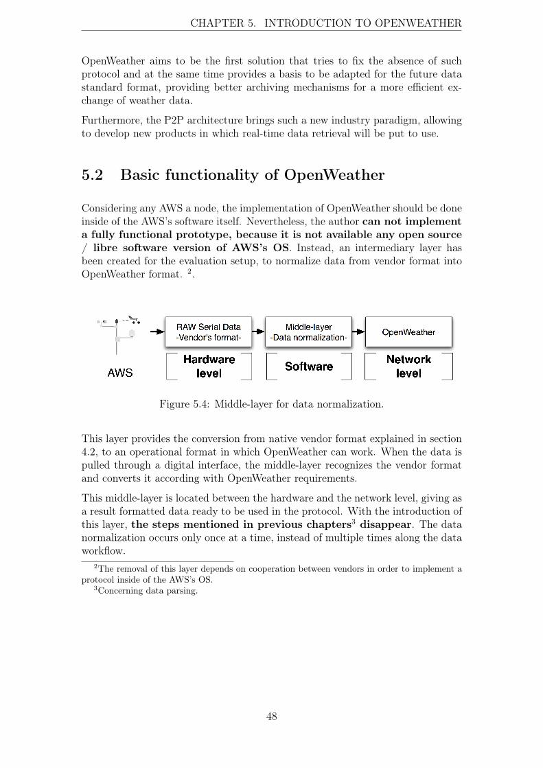
CHAPTER 5. INTRODUCTION TO OPENWEATHER
OpenWeather aims to be the first solution that tries to fix the absence of suchprotocol and at the same time provides a basis to be adapted for the future datastandard format, providing better archiving mechanisms for a more efficient ex-change of weather data.
Furthermore, the P2P architecture brings such a new industry paradigm, allowingto develop new products in which real-time data retrieval will be put to use.
5.2 Basic functionality of OpenWeather
Considering any AWS a node, the implementation of OpenWeather should be doneinside of the AWS’s software itself. Nevertheless, the author can not implementa fully functional prototype, because it is not available any open source/ libre software version of AWS’s OS. Instead, an intermediary layer hasbeen created for the evaluation setup, to normalize data from vendor format intoOpenWeather format. 2.
Figure 5.4: Middle-layer for data normalization.
This layer provides the conversion from native vendor format explained in section4.2, to an operational format in which OpenWeather can work. When the data ispulled through a digital interface, the middle-layer recognizes the vendor formatand converts it according with OpenWeather requirements.
This middle-layer is located between the hardware and the network level, giving asa result formatted data ready to be used in the protocol. With the introduction ofthis layer, the steps mentioned in previous chapters3 disappear. The datanormalization occurs only once at a time, instead of multiple times along the dataworkflow.
2The removal of this layer depends on cooperation between vendors in order to implement aprotocol inside of the AWS’s OS.
3Concerning data parsing.
48

CHAPTER 5. INTRODUCTION TO OPENWEATHER
Original sender AWS data:0r2,Ta=10.6C,Tp=10.8C,Ua=74.6P,Pa=1006.0HKHKOpenWeather’s format:"Data" : {
"PTU" : {"Air-Temperature" : "23.6","Relative-Humidity" : "14.2","Air-Pressure": "1026.6"
}
Table 5.1: Comparison of one vendor format against OpenWeather JSON format.
When data is normalized by this intermediary layer, the AWS is ready to operateinside of OpenWeather network. This intermediary layer will not be needed if thevendors establish a process of standardization.
5.2.1 Peer to Peer Architecture
As mentioned in section 5.1, OpenWeather is designed based on a P2P architec-ture. The RFC 5694 (Peer-to-Peer (P2P) Architecture: Definition, Taxonomies,Examples, and Applicability)[8], defines a P2P system as the following:
[...] We consider a system to be P2P if the elements that form the system sharetheir resources in order to provide the service the system has been designed toprovide. The elements in the system both provide services to other elements andrequest services from other elements. [...]
OpenWeather is according with the definition established by the RFC 5694 [8]. Theprotocol is thought to share the resources available in an AWS and at the sametime request services from others. In order to function properly the OpenWeathernetwork requires a minimum activity that must be performed by the nodes (aspeers’s list exchange).
Note that user itself is considered to be a node. It is not necessary to havean AWS in order to be considered a node. A node is part of OpenWeathernetwork, interacting with other nodes, sending and retrieving data, while timeoffering services to them4.
An OpenWeather node possesses the following properties:
• A node has a unique ID within OpenWeather’s network
• The geographical location of a node is essential to its connection inorder to OpenWeather’s network
• A node of the OpenWeather network can require the use of Network addresstranslation (NAT)[21] 5
4Thus, a user without an AWS can interact with other nodes offering for example peer listexchange.
5As described in RFC 5128 (State of Peer-to-Peer (P2P) Communication across Network Ad-
49
CHAPTER 5. INTRODUCTION TO OPENWEATHER
Opposed to other P2P networks, OpenWeather does not use the P2P architectureto archive a better performance transmitting big amounts of data6; the justificationof use of P2P architecture in OpenWeather is based on the distribution of thenodes and for better interaction with them. The centralized model, fails to utilizeits ability to use weather data from different collections points without a pre-normalizing data. In addition, the P2P architecture enables scaling of the networkas well, as giving the advantage of not being restricted by the limitations of acentral node.
5.2.2 Service Oriented Architecture in nodes
As explained in section 3.1.2, an AWS produces real-time data collected by itssensors. At the same time some AWS are able to store specific data in persistentmemory such as averages figures, daily reports, etc. These features provide twodata use cases for OpenWeather:
• Data becomes available in real-time
• Data can be retrieved on demand without the need to be real-time specific
OpenWeather handles these use cases providing an extra layer based on SOA.In order to achieve this, OpenWeather provides a mechanism to discover whichservices being available in a particular node, being possible after the initializationof the session, to interact with these services.
dress Translators (NATs)[41], will be recommendable to implement the TCP/UDP Hole Punchingtechnique in OpenWeather’s software, in order to avoid peer connectivity issues.
6In fact, as explained in section 3.1.2, the amount of data generated by a node is insignificantlysmall.
50

CHAPTER 5. INTRODUCTION TO OPENWEATHER
Figure 5.5: OpenWeather stack over TCP/IP.
The fundamental reasons of choice of SOA for OpenWeather, is to facilitate theaccessibility of the data. A user can be both interested in receiving only real-timedata or in to retrieving a particular chunk of data. To provide this capability, theprotocol must be SOA oriented, in order to alleviate data access through theseservices.
Figure 5.6: Uses cases available in OpenWeather via SOA.
51

CHAPTER 5. INTRODUCTION TO OPENWEATHER
Real-time data messages flow is considered to be as a continuos service offered bythe AWS via OpenWeather. Additionally, the possibility to retrieve saved data inthe AWS exits. Both real-time data and data on demand, is sent and retrievedthrough OpenWeather data message system, using JSON. Thus, OpenWeather of-fers the same possibilities as the common methodologies currently used by the ven-dors explained in chapter four, moreover the chance to get real-time data througha reliable and efficient way.
5.3 Summary
In this chapter we gave an introduction of OpenWeather, highlighting the generalguidelines applied in its design. We exposed some of the principles used in Open-Weather nodes we considered some possible examples of future applications usingOpenWeather.
We introduced the areas in which OpenWeather can have a contribution or impact.Projects as GOS or SMEAR[40] seeking for new technologies for data acquisition,could get a positive use of OpenWeather concepts.
In addition, the basic functionality of the protocol, such as its architectural prin-ciples or software model implementation have been introduced as well.
52

Chapter 6
Protocol specification
In this chapter, the OpenWeather protocol specifications are explained.
6.1 Definitions
The following subsections summarized the role of the elements involved in theprotocol. Some of the definitions are widely used in other protocols.
OpenWeather network
The nodes used in OpenWeather protocol conform to OpenWeather network stan-dards. Inside of this network a node is able to interact with other nodes, request-ing and delivering services to other nodes. These services are oriented to provideweather data. Because OpenWeather is based in a P2P architecture, its topologyis decentralized. This topology makes the nodes independent of central nodes inorder to interact between them.
OpenWeather node
A node is an active or passive element connected to OpenWeather network. Onenode can offer none to multiple services. An element is considered a node when ithas a working implementation of OpenWeather protocol and is connected to thenetwork.
Peer
Every node is considered a peer of OpenWeather network. All nodes in Open-Weather network are able to be clients and servers at the same time. This isestablishing the basis of the P2P architecture used in OpenWeather. A peer must
53
CHAPTER 6. PROTOCOL SPECIFICATION
be able to offer services to others peers, however it is not mandatory to offer aservice1 in order to be connected to OpenWeather’s network.
Weather data
The purpose of OpenWeather is to create a network in which the data exchangecomes from the weather data sources. To obtain this data the nodes can be con-nected to an AWS or other system of weather data collection. OpenWeather doesnot differentiate between the original source of the instrument’s brand, becausedata normalization2 is required in order to make the data network available.
6.2 Architecture
As it is mentioned in section 5.2.1, the architecture used in OpenWeather matchesthe requirements mentioned in the RFC 5694 [8], with OpenWeather containingnodes offering and requesting services between them.
The technical reasons why a P2P architecture is a better network solution for atopology as define by default by the AWS, are supported in the following points:
• An AWS is an individual entity being part of a bigger network that does notneed a centralized model except for data processing.
• The process executed over the weather data in order to extract meaning-ful conclusions does not posses a technical requirement to be linked to thenetwork layer.
• The collection point model forces the node to depend exclusively on one nodein the network, adding unnecessary risks to the data flow.
• The common architecture used in the weather data flow, is forced by thelegacy of the protocols used within it.
The P2P architecture is chosen by OpenWeather because it brings autonomy androbustness to the nodes. In addition, it provides the network the capability to scaleand to share resources without single dependencies. Moreover, the geographicalsituation of the nodes, is suitable for developing models in which the nodes cancollaborate to distribute the data. Finally, the P2P architecture provides thecapability to retrieve data directly from the node, without going through a commonpoint that can be collapsed or not available.
1Doing reference here to high-level services related with the data delivery, de facto, a peer isalways offering a minimum amount of services integrated within the protocol, needed to interactin the network.
2As it was explained in chapter 3 and chapter 4, this step is required because it is not possibleto modify AWS’s OS without the vendor’s collaboration.
54

CHAPTER 6. PROTOCOL SPECIFICATION
6.2.1 Standards used for data units
OpenWeather does not provide the weather date measurement units. The protocolis designed to deliver weather data formatted according to the data units specifiedin International Standard Organization (ISO) 80000 [27] family and the Guide toMeteorological Instruments and Methods of Observation [46].
Table 6.1 provides the data units used in the prototype:
Data field Data unit AcronymAir-Temperature Celsius CRelative-Humidity Percentage % RHAir-Pressure Hectopascals hPaWind direction Degress degreesWind speed Meters per second m
s
Rain accumulation Millimeters mmRain duration Seconds sRain intensity Millimeters per hour mm
h
Rain peak Millimeters per hour mmh
Hail accumulation Hits per square centimeter Hitscm2
Hail duration Seconds sHail intensity Hits per square centimeter per hour Hits
cm2h
Hail peak Hits per square centimeter per hour Hitscm2h
Table 6.1: Data units implicit on the data fields.
Since the data units have a known standard, the author considers that it is notnecessary to increase data messages sizes and data fields, but only to provide thedata units. Instead, it is more pragmatic and efficient to assume that weatherdata will be supplied with appropriate data units. It is necessary to highlight thatdespite the absence of network protocol for weather data, the vendors maintain astrict control of data units used in the AWS, facilitating this the implementationof OpenWeather across vendors.
6.2.2 Nodes
A node connected to a OpenWeather network behaves as a deterministic finiteautomaton, not executing without a clear definition operations or a definite result.All the operations performed by the nodes are identified by codes placed in theMetaInfo data field. Any data message delivered in OpenWeather protocol containsall information3 required to identify the type of operation to be performed by thesoftware when the data message is received / delivered.
Any data requested or delivered by a node using OpenWeather is based on a requestand a confirmation of it. With this mechanism the nodes are notified of statusof the operations of execution in the application layer are successful or not. This
3Through the protocol code.
55

CHAPTER 6. PROTOCOL SPECIFICATION
same mechanism is implemented in protocols as HTTP[22] in order to control thestatus of retrieval and delivery operations.
A node is able to interact with multiple nodes, being only limited by the bandwidthand system resources availability. OpenWeather does not define a minimum ormaximum of connections needed, however a node requires a >=1 number of peerson its internal list in order to interact with OpenWeather network.
Automatic Weather Stations as individual nodes
The section 3.1.2 explains how the AWS are categorized as embedded systems.By the definition, an embedded system has certain limitations in data processingand data delivery. Nevertheless the AWS are still able to do some networkingoperations and data processing when the size of them is small. OpenWeather hasbeen designed to work around these limitations.
Taking this as a basis, OpenWeather transforms the centralized model currentlyused by the industry, to a decentralized model taking advantage of a P2P archi-tecture. OpenWeather considers every AWS as a node using SOA. Because theAWS are under constant connection and deliver data to collection points, the onlymodification needed in the equipment is to change the network protocols used todeliver this data4.
Instead of using an architecture in which the AWS plainly sends the data over thenetwork without any further interaction, OpenWeather provides the mechanisms toconvert the AWS to an entity able to respond to the data requests made by the userin real-time. Although all of this process can be handled through the centralizedmodel, the independence of nodes from the collection point is mandatory in orderto achieve scalability and data accessibility. For instance, a user located outsideof a specific network of AWS, can not access the data produced by them withoutthe need to go through the collection point5, this use case avoids any possibility tocombine data in real-time from different AWS in different geographical locations,restricting any possibility to interact directly with the AWS.
Enabling the AWS to behave as a nodes, the protocol provides the basis to takeadvantage of the real-time data and at the same time fix the issues exposed inchapter four. Though this thesis sets an ambitious goal: the transition from acentralized model to a decentralized model, it has to be noted that the industryhas been using the same technologies for decades, not taking advantage of theimprovements made in the networking technologies, concerning data delivery andacquisition. The decentralized models have a proven successful track, offeringscalability and robustness.
As any other network protocol, OpenWeather has a defined set of operations.These operations provide the core principles to deliver and retrieve data fromnodes. However, these principles do not need to contain the whole data flow.
4An adaption of the AWS’s OS will be required in order to integrate the OpenWeather’s stackinside of the AWS.
5If the AWS work but the collection point is down, the data will not be accessible.
56

CHAPTER 6. PROTOCOL SPECIFICATION
Super-nodes
OpenWeather refers to super-nodes to those nodes with static IP / hostname,which are always available to exchange peer lists. Unlike other P2P applications,an OpenWeather super-node does not have any other extra property, except itsbandwidth availability 6 and an updated list of peers, to deliver to the other nodes.The role of a super-node is to be always available and to provide updated peerlists to those nodes without one. This is enough to guarantee that the nodes willbe able to connect to it if they can not find other nodes available.
Peer list calculation algorithm
One of the biggest challenges of the P2P architecture is to identify which peersare superior to others. This issue is mostly found in those architectures in whichthe purpose of the network is to transfer data based on user reputation7. Sinceall nodes are consider peers containing unique data, OpenWeather does not makedistinction amount them.
Even so, for practical reasons, it is necessary to develop an algorithm to calculatewhich peers are better than others in terms of connectivity and bandwidth avail-ability, to provide a list to the nodes to guarantee the connection to OpenWeathernetwork.
The author considers that due to the nature of the data and the main factor ofits importance is availability. Thus, the algorithm shall be a node bandwidth,network latency and geographical location.
Bandwidth and latency are two obvious and common used factors in other P2Parchitectures. However in this case is important to note that most of these nodesare going to have better network visibility with nodes are located in proximity. Thegeographical location of the node, available in the MetaInfo data field through the"Location" data field, can be used to calculate the closest peers.
The algorithm to calculate the best peers to keep on the internal list, is too avast and complex topic to be analyzed in this thesis. In the prototype created,the author used random peers in order to verify the protocol specifications. It isnecessary to highlight that the peer list calculation must be analyzed deeply inorder to implement OpenWeather in production scenario.
Node identification
In section 5.2.1 is mentioned that a node has a unique ID. This ID is used toidentify the node and at the same time by the user/software to recognize whichnode is currently active. The value of this ID is based on SHA-256[34]. Neverthe-less, the length of it and its alphanumeric composition make it really difficult toremember the node ID, even when using some mnemonic techniques. However, it
6It must be higher than average so that it may process higher network traffic.7Meaning the amount of data shared and uploaded to other peers.
57

CHAPTER 6. PROTOCOL SPECIFICATION
can be easily fixed with a proper algorithm, based on a standardized AWS systemfor identification and use of the RFC 3986 Uniform Resource Identifier (URI):Generic Syntax [6].
As example, the CWOP uses different parameters[31] to identify the AWS; someof them are:
• Block number 2 digits representing the WMO-assigned block
• Station number 3 digits representing the WMO-assigned station
• Place name: common name of station location
• Country name: country name is ISO short English form
The block number refers to the geographical region8 of the AWS, and the stationnumber is assigned base on the nearest 10 degree meridian which is numericallylower than the station longitude[31]. The place name and country name are valuesassigned based on the geographical location of the AWS. Although CWOP alsoprovides the latitude and the longitude, their introduction in Uniform ResourceLocator (URL) generation, will cause greater complexity.
02;974;EFHK;Helsinki-Vantaa;;Finland;6;60-19N;024-58E;60-19N;024-58E;51;56;P
Table 6.2: Example of CWOP’s AWS identification.
The table 6.2 shows all data used by CWOP to identify an AWS, the the followingsyntax is used to generate the URL:
owp://Country Name/Place Name/Block number + Station number
Table 6.3: ID partially based on CWOP notation.
Based on the data used in the table 6.2 the output will be:
owp://finland/helsinki-vantaa/02974
Table 6.4: ID’s partially based in CWOP’s identification system.
The scheme is denominated as owp (OpenWeather Protocol), the authority fieldis used for country name, the absolute path is based on the place name and thestation number assigned by the WMO. This combination is enough to guaranteethe uniqueness of the node accessed through the URL.
The value of the ID used in the OpenWeather data message will be the resultinghash of the data "02;974;Helsinki-Vantaa;;Finland" generated with SHA-256.
8Extracted from station index numbers database, CWOP Meteorological Station LocationInformation [31].
58
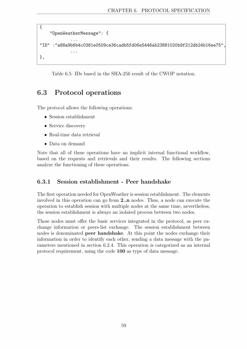
CHAPTER 6. PROTOCOL SPECIFICATION
{"OpenWeatherMessage": {
..."ID" :"a88a9b6b4c0381e0509ce36cadb5fd06e5446ab23881020b9f212db24b16ee75",
...},
Table 6.5: IDs based in the SHA-256 result of the CWOP notation.
6.3 Protocol operations
The protocol allows the following operations:
• Session establishment
• Service discovery
• Real-time data retrieval
• Data on demand
Note that all of these operations have an implicit internal functional workflow,based on the requests and retrievals and their results. The following sectionsanalyze the functioning of these operations.
6.3.1 Session establishment - Peer handshake
The first operation needed for OpenWeather is session establishment. The elementsinvolved in this operation can go from 2..n nodes. Thus, a node can execute theoperation to establish session with multiple nodes at the same time, nevertheless,the session establishment is always an isolated process between two nodes.
These nodes must offer the basic services integrated in the protocol, as peer ex-change information or peers-list exchange. The session establishment betweennodes is denominated peer handshake. At this point the nodes exchange theirinformation in order to identify each other, sending a data message with the pa-rameters mentioned in section 6.2.4. This operation is categorized as an internalprotocol requirement, using the code 100 as type of data message.
59
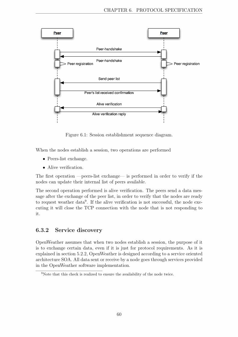
CHAPTER 6. PROTOCOL SPECIFICATION
Figure 6.1: Session establishment sequence diagram.
When the nodes establish a session, two operations are performed
• Peers-list exchange.
• Alive verification.
The first operation —peers-list exchange— is performed in order to verify if thenodes can update their internal list of peers available.
The second operation performed is alive verification. The peers send a data mes-sage after the exchange of the peer list, in order to verify that the nodes are readyto request weather data9. If the alive verification is not successful, the node exe-cuting it will close the TCP connection with the node that is not responding toit.
6.3.2 Service discovery
OpenWeather assumes that when two nodes establish a session, the purpose of itis to exchange certain data, even if it is just for protocol requirements. As it isexplained in section 5.2.2, OpenWeather is designed according to a service orientedarchitecture SOA. All data sent or receive by a node goes through services providedin the OpenWeather software implementation.
9Note that this check is realized to ensure the availability of the node twice.
60

CHAPTER 6. PROTOCOL SPECIFICATION
Figure 6.2: Service discovery sequence diagram.
The nodes involved in the session must exchange the type of data messages, in orderto be aware of services available to the nodes. Note that this operation informs thenodes which sensors are available to other nodes and which kind of weather datacan be retrieved from them. After the nodes communicate through the servicesavailable, other operations as real-time data retrieval or data on demand, can beperformed.
6.3.3 Real-time data retrieval
When the nodes establish the session and service discovery operations is performedsuccessfully, they are consider to be ready to send and receive weather data betweenthem. As it is explained in section 5.2.2, the data can be real-time data or dataon demand. In case of real time data, the node requesting it, must send a typeof data message with code 200, immediately after, the other node involved in thesession, must start to delivery real-time data messages.
61

CHAPTER 6. PROTOCOL SPECIFICATION
Figure 6.3: Real-time data sequence diagram.
The real-time data will be deliver until the node requesting it decides to stopthe data stream10. This data stream provides the real-time data generated in theremote AWS. As in any other network solution the delay that the nodes can expe-rience can affect the delivery of the data. Nevertheless, all the data messages aretimestamped when the data was assembled within them. Because this timestampis available, it will be feasible to implement an algorithm on the software side,applying a correction factor to the timestamp based on the latency of the nodes,to fix this issue.
6.3.4 Data on demand
Apart from the the real-time data, a user can request data on demand. Whena user requests data on demand, it creates individual requests with a specifictimestamp. Based on these requests, the remote node will deliver an individual
10The data streams can be interrupted by other exceptions as connectivity or software issues.
62

CHAPTER 6. PROTOCOL SPECIFICATION
data message timestamped with the date and time provided, the requests and theweather data on that time.
Figure 6.4: On demand data sequence diagram.
OpenWeather does not support the capability to request a range of dates or timeson protocol level, meaning that it is not possible to retrieve isolated weather datasamples form the node during a certain period of time. Instead, it is possibleto implement on the software side the functionality to process a group of datamessages with a certain timestamp. The justification of this limitation is based onthe bandwidth availability in an AWS. In contrast with individual weather datasamples, a range of them can have a considerable size and this can cause significantobstacles for the AWS: heavy CPU load, bandwidth consumption, etc.
6.4 Data messages
A data message refers to the data transmitted using the OpenWeather protocol. Adata message can contain multiple informational values, referring to weather dataor data needed for protocol maintenance.
63

CHAPTER 6. PROTOCOL SPECIFICATION
All data fields contained in an OpenWeather data message are considered to beencapsulated data represented through JSON objects using Universal CharacterSet - Transformation Format (UTF)-8[13][47] as character encoding. Accordingwith the RFC 4627[16], the definition of an JSON’s object is:
[...] An object is an unordered collection of zero or more name/value pairs, where aname is a string and a value is a string, number, boolean, null, object, or array.[...]
Therefore, any data field contained in an OpenWeather data message, is an indi-vidual or group of JSON objects or values. These objects are optimized accordingto the data that they contain. For instance, some data fields are JSON objectscontaining other objects at the same time. The data optimization made in the pro-tocol using these data structures, allows data encapsulation which makes enablesa fast data the data processing from the network to software levels.
All OpenWeather data messages are formatted using JSON syntax. Type of datacontained in the data message is insignificant as it is structured in one JSON objectcomposed for different sub-objects. These objects are represented as data fields interms of networking architecture.
Figure 6.5: OpenWeather data message structure.
The parent object is denominatedOpenWeatherMessage; this object is presentin all the data messages inside of OpenWeather network. This parent containstwo sub-objects; the MetaInfo object and the Data object or Info object. The
64

CHAPTER 6. PROTOCOL SPECIFICATION
MetaInfo object is a data field acting as the header of the data message inOpenWeather protocol11. Furthermore an OpenWeather data message containsthe Data object or the Info object. The Data object is a data field containing alldata related to the weather data that the data message transports. The Info objectcontains the information used internally by the OpenWeather protocol.
6.4.1 Header
OpenWeather uses a fixed12 header data field in all the data messages, in orderto guarantee its functioning. The function of this header is to provide all neces-sary data parameters needed by the OpenWeather protocol in every data message.Though it requires some data repetition, its insignificant size of this header, com-pensates the disadvantages of its repetition during transmission.
Table 6.4.1 shows the fields contained in the header:
{"OpenWeatherMessage": {
"Type" : "","MetaInfo" : {
"ID" : "","Peer-IP": "","Port": "","Location": "","Update-Interval": "","Peers-request":"","Keep-Alive":"","Bandwidth": "","Timestamp" : "","Version" : "",
},
Table 6.6: Header field (Header object) in a data message of OpenWeather.
As the table 6.4.1 exposes all data messages start with the term ”OpenWeather-Message”, building JSON parent object of the data message. Any data containedwithin the data message will belong to this parent object. Although this hierarchydoes not impact the data message size, it provides significant assistance to the postprocessing of the data on the software side. This design is inspired by the sameconcepts use in eXtensible Markup Language (XML) and XML Schemas [14], con-cerning the metadata fields. Nevertheless, OpenWeather does not providing anyextra fields for metadata definition, meaning that the software utilizing Open-Weather, should recognize the expected format beforehand13. With this practice
11This object is added an individual data field named "Type", explained in the next section.12In terms of data fields provided.13XML allows data type provision in the data itself. However, this practice increases the size
of the data considerably.
65

CHAPTER 6. PROTOCOL SPECIFICATION
speed up and simplifies the parsing compare to XML.
6.4.2 Types of data messages
The second field contained in an OpenWeather’s message is denominated Type.This field indicates which type of data is located within a data message througha numerical code and if it is related with weather data, peers exchange, protocolitself, etc.
Depending on the type of data message it will be in one of the following categories:
• Data messages for protocol maintenance only.
• Data messages use to transport weather data only.
– Real-time data.
– Data on demand.
6.4.3 Protocol codes
The "Type" field can contain a numerical value from 1..n. This numerical valueis known as the protocol code associated with the type of messages. The codesused are divided in categories and subcategories:
• Codes assigned to data messages used for protocol maintenance.
– Protocol codes (From: 1..1xx)
∗ Requests
∗ Retrievals
∗ Status
· Success
· Error
• Codes assigned to data messages for weather data exchange between peers:
– Peer codes
∗ Requests
· Real-time data: 200
· Data on demand: 201
∗ Retrievals
· Real-time data: 300
· Data on demand: 301
∗ Status
66

CHAPTER 6. PROTOCOL SPECIFICATION
· Success: 500..599
· Error: 600..699
The numerical value is used by the software in order to recognize the data pro-cessing procedure.
All the protocol codes used in the prototype are available in the appendix.
6.4.4 MetaInfo data field
The MetaInfo data field (MetaInfo JSON object) defines fixed data fields transmit-ted in every data message. The purpose of these fields is to provide all informationneeded, in order to identify the peer’s ID, its geographical location, IP address,among other data. The use of this data throughout all data messages makes allowsfor easier implementation and extensibility of the P2P architecture, as it enablesthe software to be aware properties and status of a specific peer at all times.
The MetaInfo field contains the following data fields:
• Bandwidth
• ID
• Keep-Alive
• Location
• Peer-IP
• Peers-Request
• Port
• Timestamp
• Update-Interval
• Version
The MetaInfo data field is structure as a JSON object containing an array ofelements14. These elements are the fields mentioned above. Every element doesreference to an specific parameter needed by OpenWeather protocol.
14Note: in the following figures the expression "ARRAY DATA ELEMENTS" is used to referthe MetaInfo data fields.
67

CHAPTER 6. PROTOCOL SPECIFICATION
{"OpenWeatherMessage": {
"Type" : 1,"MetaInfo" : {
ARRAY DATA ELEMENTS},
},
Table 6.7: MetaInfo field in a data message of OpenWeather protocol.
Figure 6.6: OpenWeather MetaInfo data field with data array elements.
Bandwidth
As any other network oriented software, the amount of bandwidth is a criticalfactor in its proper functionality. Most software solutions using P2P architectureoffer a dedicated section to control the bandwidth parameters. OpenWeather in-forms others nodes of the amount of bandwidth that a node has available whilegiving full control of the amount of bandwidth and connections and remote con-nections allow. As opposed to mainstream solutions, in which the node is onlycontrols the amount of connections and bandwidth locally, the bandwidth controlin OpenWeather can be managed both locally and remotely. To achieve this, thefield "Bandwidth" is provided in every data message, informing the nodes what isthe capacity of the node whereby are operating.
68

CHAPTER 6. PROTOCOL SPECIFICATION
{"OpenWeatherMessage": {
..."Bandwidth" : "4", // Correspondency 1 Megabit/s...
},
Table 6.8: Bandwidth field in a data message of OpenWeather
The user must provide this parameter to configure its node. Due to the a bigamount of possibilities for bandwidth quality, this data field contains a numericvalue that should be translated by the software to bits per second. Nevertheless,if the user considers that its bandwidth does not fit in the categories provided, itis possible to provide an integer number that will be translated by the softwareto bits per seconds. Thus, if the "Bandwidth" data field contains a numeric valuehigher than 6, the value will be translated for the software to bits per second. Thisfeature allows the user to use a custom parameter.
Numeric value Bandwidth equivalency0 56 kbit/s1 128 kbit/s2 256 kbit/s3 512 kbit/s4 1 Mbits/s5 10 Mbits/s6 100 Mbits/s
Table 6.9: Bandwidths equivalency in Bandwidth data field.
ID
As explained in sections 5.2.1, every peer has an unique ID throughout Open-Weather’s network. In fact, its properties make it theoretically unique in theworld.The ID is generated based in the AWS identification. The ID data field isthought to be representation of the AWS, such representation is the result of thehash applied over some identification system for AWSes15.
If the AWS is not part of some identification system, its ID can be generated ran-domly by the software, however is highly recommended to provide an ID assignedfor some organization as the CWOP or NOAA.16.
15Several weather organizations provide this identification.16In the evaluation setup, the author uses a random ID.
69

CHAPTER 6. PROTOCOL SPECIFICATION
{"OpenWeatherMessage": {
..."ID" :"4f9a67e8496d69b8707858576ec12b8aa3fa5519c23a79ea071dc7dbc0c9b2e3",
...},
Table 6.10: ID’s field in a data message of OpenWeather protocol.
Keep-Alive
Due to possible node connection instability, it is necessary to implement a mech-anism to identify the current connection status with a specific node is, on theapplication layer level. OpenWeather implements the field "Keep-Alive". Thisfield provides the amount of time that the software must wait until the connectionis close.
{"OpenWeatherMessage": {
..."Keep-Alive" : "120000",...
},
Table 6.11: Keep-Alive field in a data messages of OpenWeather protocol.
When a node stops sending data to other node/s, the connection will be closedwhen the sum of the timestamps of the last data messages received and the "Keep-Alive" value, is less than the current date and time.
The protocol assumes that if the node is not delivering data, is not useful to keep aconnection with it. The same principle is applied in a number of network orientedsoftware solutions. The value of this field is expressed in milliseconds, and by thedefault has a timeout of 120000 milliseconds (2 minutes). Though possible,the customization this parameter is not recommended, as it assumes responsibilitybetween nodes when necessary.
Location
The "Location" field does reference to the geographical coordinates of the node,expressed in the Universal Transverse Mercator (UTM) system. This data fieldhas two different functions:
• Identify the geographical location of the node.17
17Mandatory due to the nature of the data.
70

CHAPTER 6. PROTOCOL SPECIFICATION
• Provide identificational information to other peers, does providing them withthe updated information which store in the node’s internal list. 18
{"OpenWeatherMessage": {
..."Location" : "4597807 269999 30T",...
},
Table 6.12: Location field in a data messages of OpenWeather protocol.
This field should be filled manually by the user. It is highly recommended toprovide this parameter with as much accuracy as possible.
Peer’s IP address & port
The MetaInfo’s field contains two fields dedicated to TCP/IP:
• Peer-IP
• Port
The field "Peer-IP" contains the public IP address assigned to the computer’snetwork interface that is running the software supporting OpenWeather’s proto-col.This field can be an IP address using 32-bit number (IPv4) or 128 bit number(IPv6). The introduction of this field is based on the requirement of the protocolto possess an updated address of the peer in order to able to connect to it. Thoughthe field is labeled as "Peer-IP" not necessarily must be the numeric address. Itis possible to implement the OpenWeather protocol to use hostname resolutionbased on Dynamic Name Server (DNS) requests19, with a few modifications on thesoftware’s side.
The field "Port" contains the port used in the TCP to establish a connection withthe peer. The default TCP port number is 625352021nevertheless any port can beused inside of TCP’s range always that it does not conflict with other ports.
18This is explained deeper in section 7.2.19However as it is implicit in the use of DNS, it will be required to have the hostname of the
peers recorded in the name servers.20Port number choose according with the range of ports available for dynamic and/or private
use published by IANA[5].21We assume fixed ports and port forwarding techniques for this. The functioning of Open-
Weather behind firewalls or/and NAT is out of the scope of this thesis.
71

CHAPTER 6. PROTOCOL SPECIFICATION
{"OpenWeatherMessage": {
..."Peer-IP" : "140.186.70.148","Port": "62535",...
},
Table 6.13: Peer-IP & Port fields in a data message of OpenWeather protocol.
Both fields, "Peer-IP" and "Port", are present in others P2P architectures22, thereason for this is that these fields facilitate a significant part of the software imple-mentation and the network functionality. Adding these fields to all data messages,enables the software to keep the peer list updated and working between nodes andat the same time it facilitates the protocol session establishment.
Peers-Requested
The "Peers-Requested" field provides the number of peers that the node requeststo other nodes in order to fill its internal list of peers. In a P2P architecture itis critical to keep an updated list of peers to guarantee successful delivery of thedata throughout the network. By default this field is set to 20, with a possiblerange of 1..100.
{"OpenWeatherMessage": {
..."Peers-Requested" : "20",...
},
Table 6.14: Peers-Requested field in a data messages of OpenWeather protocol.
Timestamp
As explained in chapter two, the success of weather prediction depends on differentfactors. One of the most important variables are the geographical location and thetime and date, in which the weather data samples were collected. OpenWeatherprovides the field "Timestamp" to supply a solution for this condition. Every datamessage contains the timestamp in which the data was assembled. This providesa feasible mechanism to know when the weather data sample by the data messagereceived was collected.
22Often denominated with different terms and syntax.
72

CHAPTER 6. PROTOCOL SPECIFICATION
The data format used by OpenWeather protocol follows the RFC 3339 (Date andTime on the Internet: Timestamps)[28] and it follows the guidelines establishedby the ISO 8601:2004[20] as well. All data messages are timestamped using theCoordinated Universal Time (UTC).23
{"OpenWeatherMessage": {
..."Timestamp" : "2011-05-29T12:10:23Z",...
},
Table 6.15: Timestamp field in a data message of OpenWeather.
Note that OpenWeather protocol does not use the timestamp value for any purposerelated with protocol operations. This Timestamp field is provided in order to fitthe requirements of the weather data. Because the weather data requires precisestamping of the time in which it was acquire, this field is introduced. In addition,as in other real-time data systems, it is recommended to sync the time of the nodeusing protocol such as Network Time Protocol (NTP), to guarantee the quality ofthe data. Such synchronization must be managed independently of OpenWeather.
Update-Interval
The "Update-Interval" field contains the time value, expressed in milliseconds,that other peers should wait before to requesting protocol information. This fieldcan be used to manage data availability provided absence of network congestion.
{"OpenWeatherMessage": {
..."Update-Interval" : "120000",...
},
Table 6.16: Update-Interval field in a data messages of OpenWeather protocol.
By default this field is set to 120000 milliseconds (2 minutes), however thisparameter that can be customize by the user.
23The conversion to the original timezone of the data message can be managed through soft-ware.
73

CHAPTER 6. PROTOCOL SPECIFICATION
Protocol versioning
Following the same principles as HTTP and other protocols, OpenWeather uses<major>.<minor> numbering scheme to indicate the versions of the protocol.The versioning is indicated in the "Version" field of the data header, adding theterm ”OpenWeather” and the character ’/’ before the numbering.
{"OpenWeatherMessage": {
..."Version" : "OpenWeather/1.0",...
},
Table 6.17: Version field in a data message of OpenWeather.
MetaInfo data field summary
The table 6.18 shows the structure of the MetaInfo data field with all array ele-ments already filled in with data:
{"OpenWeatherMessage": {
"Type" : 1,"MetaInfo" : {
"ID" :"4f9a67e8496d69b8707858576ec12b8aa3fa5519c23a79ea071dc7dbc0c9b2e3","Peer-IP" : "140.186.70.148","Port": "62535","Location" : "4597807 269999 30T","Update-Interval" : "120000","Peers-Request" : "20","Keep-Alive" : "120000","Bandwidth" : "4","Timestamp" : "2011-05-29T12:10:23Z","Version" : "OpenWeather/1.0",},...
}
Table 6.18: MetaInfo data field (MetaInfo object) in a data message of Open-Weather.
All the OpenWeather data messages will contain a header as the shown in thetable 6.18, fill in with the particular data of the node.
74

CHAPTER 6. PROTOCOL SPECIFICATION
6.4.5 Data field
As part of the MetaInfo data field (MetaInfo object), OpenWeather data messagescan contain a field named Data (Data object). This data field is a JSON objectcomposed from different sub-objects. The values or sub-objects having this objectas a parent, are dedicated to transport weather data.
The Data field is necessary in order to complement the MetaInfo data field. TheMetaInfo data field only provides information about the node itself. The data fieldcontains the data that the node retrieves or request from others nodes. The typeof data available in this data field can be:
• Real-time weather data
• Data requested/delivery in demand (non real-time)
{"OpenWeatherMessage": {
"Type" : 1,"MetaInfo" : {
ARRAY DATA ELEMENTS},"Data" : {
ARRAY DATA OBJECTS}
},
Table 6.19: Data field in a data message of OpenWeather protocol.
All phenomena data transmitted in OpenWeather uses the data units, specify in theGuide to Meteorological Instruments and Methods of Observation[46], published bythe WMO[44]. The author assumes that the protocol must follow this standard,because it is adopted by the major number of countries24. Though some countriesstill keep local units for measurements, OpenWeather protocol does not take inconsideration these use cases, nevertheless the implementation of the conversionbetween units, can easily be done on the software side.
All values or sub-objects containing information about weather data will alwayshave the Data object as a parent.. The following sections explain how thesedifferent types of data are assembled in OpenWeather.
Real-time data messages
The section 6.4.4 introduced the persistent data provided in every data message ofOpenWeather. However, this data is provided in order to guarantee the protocol’sfunctioning. A part of the header field, the data messages can contain weatherdata. This section explains how a real-time message is assembled. Note that the
24Exceptions: United States, Liberia and Myanmar (Burma).
75

CHAPTER 6. PROTOCOL SPECIFICATION
prototype used in the experimental setup only supports data extracted from thefollowing phenomena:
• PTU -Pressure, Temperature, Humidity
– Air temperature
– Relative humidity
– Air pressure
• Wind
– Direction (minimum, average, maximum)
– Speed (minimum, average, maximum)
• Precipitation
– Rain (accumulation, duration, intensity, peak)
– Hail (accumulation, duration, intensity, peak)
These data have been chosen because it is available in most of the AWS of semi-professional / end-user range. In addition, the data used in OpenWeather providesa functional prototype adapted to this thesis. The author highlights that none ofthese data fields (concerning weather data) are used claiming them to be a standardor a suggestion of it. As mentioned in section 4.3, only a process of standardizationcan provide the correct data fields to use. Nevertheless, the use of these weatherdata fields is enough to develop a prototype.
Note that some data objects contain values in the data fields such as "minimum","maximum" or "accumulation" among others, that are representing data collectedin time intervals. Depending of the phenomenon these time intervals can be com-pletely different. The recommend intervals of measurement are described in the"Guide to Meteorological Instruments and Methods of Observation" [46], and the-oretically they must be always the same independently of the brand of the weatherinstrument used.
Pressure, temperature and humidity data
The PTU, are the most common data available in an AWS, due to the close relationbetween the phenomena and the ease of its acquirability. Any modern AWS willis equipped with necessary sensors to measure these phenomena.
The AWSes collect this data in real-time, transforming the raw input data from thesensors into digital data. The workflow of this data is described in section 3.1.4.As other data in OpenWeather, it will be normalized in the layer implementedbetween the hardware layer and OpenWeather25.
0r2,Ta=18.7C,Ua=77.4P,Pa=1002.1H
Table 6.20: PTU real-time data in the raw format used by the AWS.25Explained in section 5.2.
76

CHAPTER 6. PROTOCOL SPECIFICATION
When the PTU data is transformed to OpenWeather’s format, it has the followingformat:
{"OpenWeatherMessage": {
"Type" : 1,"MetaInfo" : {
ARRAY DATA ELEMENTS},"Data" : {
"PTU" : {"Air-Temperature" : "","Relative-Humidity" : "","Air-Pressure": ""
},},
Table 6.21: PTU data field in a data message of OpenWeather protocol.
The three data fields contained in the Data object are:
• Air-Temperature: expressed in degree Celsius (°C)
• Relative-Humidity: expressed in percentage in base of relative humidity
• Air-Pressure: expressed in Hectopascals (hPa)
These data fields are encapsulated as an array of data elements inside of the JSONobject PTU. The table 6.22 shows an example of the PTU object filled with real-time data:
"Data" : {"PTU" : {
"Air-Temperature" : "20.0", // Celsius: ºC"Relative-Humidity" : "59.5", // %RH"Air-Pressure": "1002.1" // Hectopascals: hPa
},
Table 6.22: PTU data field with real-time data in a data message of OpenWeatherprotocol.
The frequency of reporting this data will depend on the configuration of the AWS.Most of AWS offer a time interval between 1 second and 3 seconds, to generatethis data.
77

CHAPTER 6. PROTOCOL SPECIFICATION
Wind data
The wind is other of the most popular phenomena to measure in AWSes. Thewind data contains two sub-objects: direction and speed.
{"OpenWeatherMessage": {
"Type" : 1,"MetaInfo" : {
ARRAY DATA ELEMENTS},"Data" : {
..."WIND" : {
"Direction" : {"min" : "","ave" : "","max" : ""
},"Speed" : {
"min" : "","ave" : "","max" : ""
}},
Table 6.23: Wind data field in a data message of OpenWeather protocol.
At the same time these two objects are composed by three array data elements:
• Direction
– Minimum (min): expressed in degrees
– Maximum (max): expressed in degrees
– Average (avg): expressed in degrees
• Speed
– Minimum (min): expressed in meters per second ms
– Maximum (max): expressed in meters per second ms
– Average (avg): expressed in meters per second ms
78

CHAPTER 6. PROTOCOL SPECIFICATION
{"OpenWeatherMessage": {
"Type" : 1,"MetaInfo" : {
ARRAY DATA ELEMENTS},"Data" : {
..."WIND" : {
"Direction" : {"min" : "217", // Degrees"ave" : "217",// Degrees"max" : "218"// Degrees
},"Speed" : {
"min" : "4.2",// m/s"ave" : "4.2",// m/s"max" : "4.5"// m/s
}},
Table 6.24: Wind data field with real-time in a data message of OpenWeatherprotocol.
Precipitation data
Precipitation is the last phenomena that typically all the AWSes measure. Insideof the concept of precipitations encompasses two different classes, rain and hail.Thus, the precipitation is structure two sub-objects containing an array of fourdata elements.
79

CHAPTER 6. PROTOCOL SPECIFICATION
{"OpenWeatherMessage": {
"Type" : 1,"MetaInfo" : {
ARRAY DATA ELEMENTS},"Data" : {
..."PRECIPITATION" : {
"Rain" : {"accumulation" : """duration" : "","intensity" : "","peak" : ""
},"Hail" : {
"accumulation" : "","duration" : "","intensity" : "","peak" : ""
}}
Table 6.25: Precipitation data field in a data message of OpenWeather protocol.
Both of them are measured with the same data fields:
• Rain
– Accumulation (accumulation): expressed in millimeters
– Duration (duration): expressed in seconds
– Intensity (intensity): expressed in millimeters per hour
– Peak (peak): expressed in millimeters per hour
• Hail
– Accumulation (accumulation): expressed in hits per cm2
– Duration (duration): expressed in seconds
– Intensity (intensity): expressed in hits per cm2
– Peak (peak): expressed in hits per cm2
Compared with the PTU or wind, precipitation may be absent in the currentweather. It means that the measurement of these phenomena will happen onlywhen it is present. Despite this, OpenWeather always delivers the precipitationdata field in the real-time data messages26.
26A zero value is assigned to the data fields when the phenomena are not present.
80

CHAPTER 6. PROTOCOL SPECIFICATION
{"OpenWeatherMessage": {
"Type" : 1,"MetaInfo" : {
ARRAY DATA ELEMENTS},"Data" : {
..."PRECIPITATION" : {
"Rain" : {"accumulation" : "12" // mm"duration" : "34", // seconds"intensity" : "12", // mm/h"peak" : "9" // mm/h
},"Hail" : {
"accumulation" : "2", //hits/cm^2"duration" : "78", //seconds"intensity" : "1", // hits/cm^2h"peak" : "1" // hits/cm^2h
}}
Table 6.26: Precipitation data field with real-time in a data message of Open-Weather protocol.
Data field overview
The table 6.27 indicates the Data field structure with all objects and their arrayelements filled with data:
81

CHAPTER 6. PROTOCOL SPECIFICATION
{"OpenWeatherMessage": {
"Type" : 1,"MetaInfo" : {
ARRAY DATA ELEMENTS},"Data" : {
"PTU" : {"Air-Temperature" : "20.0", // Celsius: C"Relative-Humidity" : "59.5", // %RH"Air-Pressure": "1002.1" // Hectopascals: hPa
},"WIND" : {
"Direction" : {"min" : "217", // Degrees"ave" : "217",// Degrees"max" : "218"// Degrees
},"Speed" : {
"min" : "4.2",// m/s"ave" : "4.2",// m/s"max" : "4.5"// m/s
}},"PRECIPITATION" : {
"Rain" : {"accumulation" : "12" // mm"duration" : "34", // seconds"intensity" : "12", // mm/h"peak" : "9" // mm/h
},"Hail" : {
"accumulation" : "2", //hits/cm^2"duration" : "78", //seconds"intensity" : "1", // hits/cm^2h"peak" : "1" // hits/cm^2h
}}
}}
}
Table 6.27: Real-time data message of OpenWeather protocol.
82

CHAPTER 6. PROTOCOL SPECIFICATION
Data on demand
As highlighted in section 5.2.2, OpenWeather possesses the capability to transportdata on demand (not being the data generated in real-time)27. In this use case,this data is only delivered by the nodes when the user requests it. To achievethis operation, OpenWeather uses the object’s hierarchy, to know which kind ofdata the user is requesting. The protocol encodes such data in OpenWeather dataheader, after that it is interpreted by the software to localize the data requestedfrom the AWS.
Note that the levels of hierarchy can be as deep as it is required. Nevertheless, theprototype only offers the possibility to retrieve the same data as in real-time.28
Figure 6.7: OpenWeather’s MetaInfo data field with the data array elements.
Through the different levels established in the object’s hierarchy, it is easy to findthe information that the user expects.
27This data can be stored in the AWS itself.28Mark with a different timestamp inside of anAWS or datalogger.
83

CHAPTER 6. PROTOCOL SPECIFICATION
As explained in section 6.4.2, OpenWeather uses numerical codes to identify thetypes of data messages. In this case the data on demand must be requested by auser (node), thus the protocol’s code will be 20129.
The data message will contain a JSON object containing an array of data elements.The data field is named "Retrieve", it contains the data requested, indicated bythe letter ’D’ as a variable to be reference for data objects requested (PTU, windor precipitation). In addition a timestamp30 is added to the request in order tospecify in which sample is interested the user.31
{"OpenWeatherMessage": {
"Type" : 201,"MetaInfo" : {
ARRAY DATA ELEMENTS},"Data" : {
"Retrive" : {["D":"PTU","D":"WIND","D":"PRECIPITATION"],"Timestamp": "2011-05-29T12:10:23Z"
}}
}}
Table 6.28: Real-time data message of OpenWeather protocol.
This request will return the PTU, wind and precipitations recorded in the times-tamp provided. The next data message received by the node in response of thiswill have exactly the same format as a real-time data message, except the codeand the timestamp in the header; they will provide referencing to the responsefor the data on demand in the date and time specified.
6.4.6 Internal protocol data
As any other P2P architecture, OpenWeather needs a certain amount of inter-nal data to keep working. Commonly, this data is focused in peer’s informationas hostnames and ports used by the nodes. OpenWeather uses a mechanism toexchange list of peers between nodes, to guarantee the well-functioning of Open-Weather network. The information provided in these data messages can havedifferent purposes. The author reserves this type of data for future implementa-
29Review the protocol codes reference.30This variable follows exactly the same standards used in the Timestamp field used in the
MetaInfo data field.31It is possible to change this field value in order to adapt it to request samples from a range
of time.
84
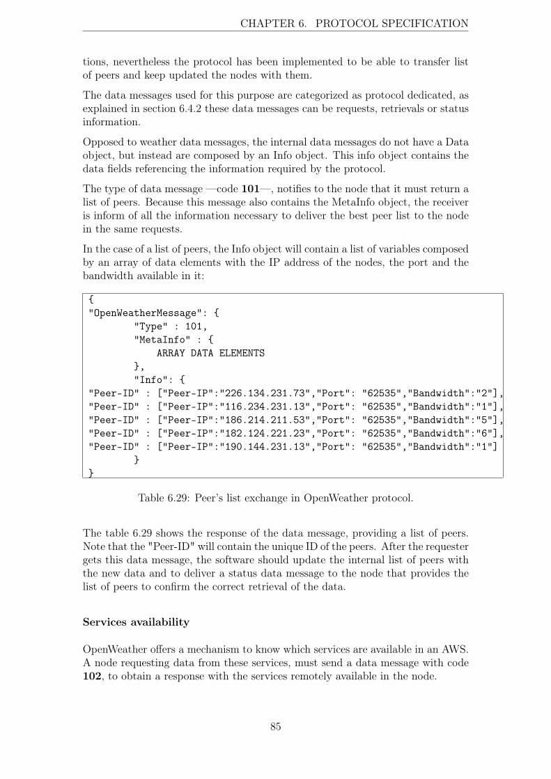
CHAPTER 6. PROTOCOL SPECIFICATION
tions, nevertheless the protocol has been implemented to be able to transfer listof peers and keep updated the nodes with them.
The data messages used for this purpose are categorized as protocol dedicated, asexplained in section 6.4.2 these data messages can be requests, retrievals or statusinformation.
Opposed to weather data messages, the internal data messages do not have a Dataobject, but instead are composed by an Info object. This info object contains thedata fields referencing the information required by the protocol.
The type of data message —code 101—, notifies to the node that it must return alist of peers. Because this message also contains the MetaInfo object, the receiveris inform of all the information necessary to deliver the best peer list to the nodein the same requests.
In the case of a list of peers, the Info object will contain a list of variables composedby an array of data elements with the IP address of the nodes, the port and thebandwidth available in it:
{"OpenWeatherMessage": {
"Type" : 101,"MetaInfo" : {
ARRAY DATA ELEMENTS},"Info": {
"Peer-ID" : ["Peer-IP":"226.134.231.73","Port": "62535","Bandwidth":"2"],"Peer-ID" : ["Peer-IP":"116.234.231.13","Port": "62535","Bandwidth":"1"],"Peer-ID" : ["Peer-IP":"186.214.211.53","Port": "62535","Bandwidth":"5"],"Peer-ID" : ["Peer-IP":"182.124.221.23","Port": "62535","Bandwidth":"6"],"Peer-ID" : ["Peer-IP":"190.144.231.13","Port": "62535","Bandwidth":"1"]
}}
Table 6.29: Peer’s list exchange in OpenWeather protocol.
The table 6.29 shows the response of the data message, providing a list of peers.Note that the "Peer-ID" will contain the unique ID of the peers. After the requestergets this data message, the software should update the internal list of peers withthe new data and to deliver a status data message to the node that provides thelist of peers to confirm the correct retrieval of the data.
Services availability
OpenWeather offers a mechanism to know which services are available in an AWS.A node requesting data from these services, must send a data message with code102, to obtain a response with the services remotely available in the node.
85

CHAPTER 6. PROTOCOL SPECIFICATION
{"OpenWeatherMessage": {
"Type" : 102,"MetaInfo" : {
ARRAY DATA ELEMENTS}
}}
Table 6.30: Services list availability request.
After this data message is received by the remote node, it will reply with anotherdata message, providing the list of the services:
{"OpenWeatherMessage": {
"Type" : 101,"MetaInfo" : {
ARRAY DATA ELEMENTS},"Info": {
"Services" : { "PTU":"RO","WIND": "RO","PRECIPITATION":"RO"}}
}
Table 6.31: Peer’s list exchange in OpenWeather protocol.
One array of data is delivered in the reply:
• Services array: indicating the type of service and its availability.32
With this information the software knows which services can be checked on theremote node and which kind of data —real-time or on demand— can be retrievedfrom them.
6.5 Protocol considerations
The following sections describe some aspects of OpenWeather related with otherprotocols or future features of it.
OpenWeather and other protocols
We can find dozens of protocols available, using P2P architectures and/or opti-mizations in the data delivery. Nevertheless, the author could not find any protocolsuitable enough to fit in the characteristic required by the AWSes. Protocols as
32R is equal to "real time data" and O to "data on demand". Both can be present or isolated.
86

CHAPTER 6. PROTOCOL SPECIFICATION
Bittorrent[10], have a proven track delivering large amount of data and scalingtheir networks properly. FastTrack[42] has been successful achieving similar re-sults as Bitorrent. However, almost all the P2P protocols are oriented to transferfiles or real-time data with a big size (such as video or voice streams). In addition,these protocols are designed focusing in nodes with common computational capa-bilities (such as desktops or small servers), not considering embedded system insideof their purpose (being difficult to handle the necessary resources to implementthese protocols on an embedded system).
Other alternatives as HTTP, were considered by the author as solutions for thisthesis. Nevertheless, HTTP still has a big dependency of the centralized model.At the same time, HTTP works under synchronously mode, something that willlimit the real-time capabilities needed for the AWSes.
Finally, because the use of FTP (a generic protocol) is under use for weatherinstruments, the author considered much more interesting to research a customsolution for the AWSes.
Nevertheless, several concepts have been taken from the mentioned protocols.OpenWeather uses the same philosophy as HTTP, providing in the header of thedata message all the information needed. The same approach as HTTP has beenchosen to identify the type of data messages. Through protocol codes the datamessage is identified in a category / purpose, being simple to extend the amountof protocol operations, just creating new identifiers through the codes. Moreover,the protocol uses JSON as data format, being text-based as HTTP. Concepts suchnode ID, peers-requested or update-interval have been taken from protocols asBitorrent[10] or FastTrack[42] . These properties allow OpenWeather to imple-ment methodologies tested in other P2P networks with successful results.
Aggregation of data between nodes
As in other P2P networks, the scalability of the OpenWeather network can bean issue. Although OpenWeather does not implement an aggregation techniquebetween the nodes, it is ready to be adapted to it. The nodes conforming toOpenWeather protocol could require the capability to request and retrieve datausing indirect paths to the end node. These paths could be found using theconnections already established with other nodes.
The aggregation of the data will be executed using the same data format as com-mon on OpenWeather protocol, thus, the data messages will use JSON format plusthe required fields in the data message to provide such functionality. The sameoperations of the protocol will be available through aggregation. In addition, theprotocol will require the implementation of new operations for internal use.
We need to consider the nature of the weather data networks when we chose theaggregation technique. As it is described in section 3.1.2, the amount of band-width is commonly limited in an AWS. Several techniques have been developed toaggregate information from different sources having in consideration connectivityand bandwidth availability issues. These techniques are classified based in howthey aggregate and route the data [35].
87

CHAPTER 6. PROTOCOL SPECIFICATION
In case that the aggregation is required in OpenWeather, it should be a combinationof gossiping and tree-based methods, in order to provide a feasible way to aggregatedata between nodes. The reason for this combination is that both methodologieshave one specified purpose. Gossiping techniques are focused into offer robustcommunications, meanwhile, tree-based techniques are focused in to have betterperformance transferring data. Because a weather network needs to guaranteethe flow of the data and at the same time the availability of the data as soon aspossible, a research combining both techniques must be performed in order to findsuitable solutions for such environment.
Notwithstanding, the OpenWeather specification available in this thesis providesthe capability to request and retrieve the list of peers of a remote node. Thecombination of this list of peers and the Keep-Alive value of them, can be usedto build a tree-based structure with the nodes that have a established session.Through this tree, OpenWeather can be able to find new paths to other nodes. Thiswill require the implementation of a internal operation of the protocol, providingthe capability to make queries to other nodes, in order to build new paths. Inaddition, the tree-based structure will not be enough to guarantee the robustnessnecessary for the weather data transmission. Hence, it will be required to findthe compatibility of this technique with gossiping methodologies, implementingan algorithm inside the protocol that periodically and randomly tries to updatethe table of nodes available, and the paths of them.
Finally, we need to highlight that the aggregation of data is a complicated area,not being possible to treat it in this thesis.
Compatibility with centralized models
In chapters two and three we introduced the different techniques and topologiesused by weather organizations to acquire weather data. The centralized modelwas explained, showing how the nodes have a strong dependency of one commonpoint. This setup is the current solution chosen by weather organizations, andalmost all big weather data networks are builded based on such infrastructure. 3Thus, it is needed to consider the compatibility of OpenWeather with this topology.Although OpenWeather is designed to have the AWSes as independent nodes,infrastructures using the centralized model, can provide a node doing a bridgebetween the collection point and OpenWeather network. It will be required todevelop the methods to retrieve the data from the subnet of the collection point.As it was mentioned in section 5.1.2 and the example of HTTP and OpenWeather,it is possible to encapsulate data to other protocols with the proper adaption.
Because every weather organization has their own setups and methodologies, anindependent study will be required in order to design a bridge from the collectionpoint models to the P2P architecture of OpenWeather.
88

CHAPTER 6. PROTOCOL SPECIFICATION
6.6 Summary
In this chapter the core architecture of OpenWeather was presented. The defini-tions establish by the protocol have been explained. The roles of nodes and theiridentification is presented to justify how OpenWeather can be adapted for futureuse in a different system for AWS identification.
We have explained the architecture of OpenWeather. Justifying the use of theAWSes as indivudal nodes conforming a P2P network. The protocol functionalityis analyzed, explaining how the different operations perform. The main character-istics of OpenWeather have been exposed.
The structure used in OpenWeather data messages has been analyzed, explaininghow JSON is used as syntax to encapsulate the data. In addition, the applicationof object hierarchy on data has been explained. All data fields, which composedata messages were defined technically.
The protocol codes and their categories have been described, justifying their nu-meration and purposes.
The differences between real-time data messages, data messages on demand andinternal data messages, have been justified, putting attention in how the differ-ent data messages have a common structure and use. Finally an example of allthe types of data messages implemented in the protocol are explained, providingenough information to implement a functional prototype of it.
89

Chapter 7
Experimental evaluation setup
In this chapter, the experimental setup used to implemented the proof of conceptof the OpenWeather protocol is explained. A generic AWS has been setup totest the protocol with real-time data. The software architecture implementing thefunctionality of the protocol is introduced as well. The purpose of this chapter isto introduce the general guidelines followed by the implementation of a prototypeof OpenWeather protocol and to analyze the tests cases performed using it.
7.1 Scenario
The AWS utilized in the experimental setup is the model WXT520, manufacturedby Vaisala Oyj. Along with other AWSes sharing these characteristics, it is ableto measure the following phenomena:
• Liquid Precipitation
– Hail
– Rain
• Relative Humidity
• Wind
– Direction
– Speed
• Air Temperature
• Barometric Pressure
The geographical location of the AWS is N 60º 11’ 15.6” E 024º 50’ 14.8”1.The AWS has been connected to a computer, in which the software developedto implement OpenWeather protocol is installed. The AWS has been configured
1UTM: Zone: 35 Easting: 380076 Northing: 6674276. Municipality of Otaniemi, Espoo,Finland.
90

CHAPTER 7. EXPERIMENTAL EVALUATION SETUP
following the manufacturer suggestions, emulating a normal installation environ-ment. The digital interface configured in the AWS is a RS-232 port, offering amaximum amount of bit rate of 116 kbit/s.
Figure 7.1: AWS installed to simulate a real scenario.
The AWS is plugged in continually 24 hours and installed on a mast of 2 meterslength. The RS-232 port provides the data acquired in the AWS to computer athat operates an implementation of OpenWeather protocol.
Thus, the AWS used to implement the protocol has not been modified to adaptit to OpenWeather, all the adaptions realized have been made through a softwareimplementation. This fact allows the verification of the adaptability of the protocolto the current technology without no major modifications to the AWS.
Evaluation setup
The evaluation setup consists four nodes. All of them run a copy of the prototype,thus acting as nodes. Nevertheless, only one node is connected to a functionalAWS, the other three simulate the weather data input2.
The table 7.1 shows nodes specifications:2Generated randomly based on the same patterns as a normal AWS.
91

CHAPTER 7. EXPERIMENTAL EVALUATION SETUP
CPU Memory Network connection Operating system Hostname2.4GHz 4GB 100Mbps GNU/Linux Node 12.2GHz 1GB 100Mbps GNU/Linux Node 2900GHz 1GB 128Kbps GNU/Linux Node 31GHz 1GB 56Kbps GNU/Linux Node 4
Table 7.1: Hardware and OS specifications of the evaluation setup.
Figure 7.2: Network topology used in the evaluation setup.
All the nodes posses network visibility among them, with maximum network la-tency less than 75 milliseconds. The bandwidth in node number two and fourhas been limited (Round-trip time (RTT)) to 128kbit/s and 56kbit/s respectively.These restrictions emulate the network limitations mentioned in chapter three.
The purpose of this setup is to create an environment that simulates commonconditions experience during weather data acquisition. All the nodes use Open-Weather protocol to exchange data between them. This environment provides thenecessary resources to test and verify the characteristics of the protocol, such datamessage size, times of response, etc.
92
CHAPTER 7. EXPERIMENTAL EVALUATION SETUP
7.2 Prototype implementation
In order to verify the feasibility and the functionality of OpenWeather, the authordeveloped a proof of concept of the protocol, to test and verify its feasibility asalternative protocol for weather data transmission. This implementation providesthe necessary data to independently evaluate the protocol.
7.2.1 Technologies used
OpenWeather is designed to have an emphasis on the data structures used in thesoftware implementation. In addition, the object hierarchy used to structure thedata makes the implementation of the protocol easier by using an object orientedprogramming language.
Thus, C++ has been chosen as the primary language used in the prototype. TheC++ standard library is used to write the intermediary layer (in combinationwith some Python scripts). Because the target of this protocol can have endusers which are not familiar with command-line applications, a functional GUIhas been implemented. The Qt framework[33] has been chosen to implement theGUI, together with QJson[9] for the data representation.
7.2.2 Software Architecture
The prototype requires to be implemented supporting the functionality describedin the P2P architecture taxonomies[8]. Thus, the nodes should posses the capabil-ity to request services, and at the same time, offer services to others nodes. Thisrequirement conditions the node to behave as a client and server at the same time.
To realize this architecture, the concept of local peer is introduced. The local peerrefers to the node itself; representing the AWS entity in the network; nevertheless,as described in section 5.2.1, a node without an AWS can be part of the networkas well.
Because the node behaves as client and server at the same time, the softwareimplementation is designed to maximize the utilization of the common resourcesbetween both modalities. Thus, the implementation of the classes have been doneusing abstract interfaces, not mattering if the data to process has been receivedthrough the client or server module.
Common implementation
The prototype implementing OpenWeather protocol has been optimized for thedata structures and object hierarchy explained in chapter six. The handling ofJSON data through TCP sockets is the basis of the implementation. The prototypefocuses its core functionality in to take advance of the most optimal way of socketsmanagement and data manipulation.
93
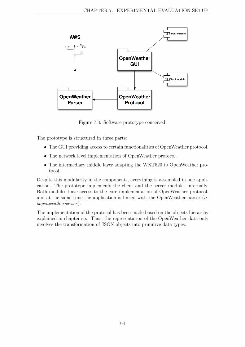
CHAPTER 7. EXPERIMENTAL EVALUATION SETUP
Figure 7.3: Software prototype conceived.
The prototype is structured in three parts:
• The GUI providing access to certain functionalities of OpenWeather protocol.
• The network level implementation of OpenWeather protocol.
• The intermediary middle layer adapting the WXT520 to OpenWeather pro-tocol.
Despite this modularity in the components, everything is assembled in one appli-cation. The prototype implements the client and the server modules internally.Both modules have access to the core implementation of OpenWeather protocol,and at the same time the application is linked with the OpenWeather parser (li-bopenweatherparser).
The implementation of the protocol has been made based on the objects hierarchyexplained in chapter six. Thus, the representation of the OpenWeather data onlyinvolves the transformation of JSON objects into primitive data types.
94
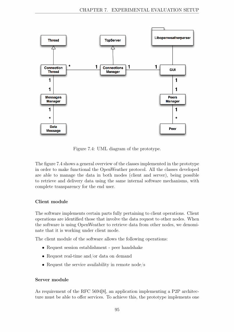
CHAPTER 7. EXPERIMENTAL EVALUATION SETUP
Figure 7.4: UML diagram of the prototype.
The figure 7.4 shows a general overview of the classes implemented in the prototypein order to make functional the OpenWeather protocol. All the classes developedare able to manage the data in both modes (client and server), being possibleto retrieve and delivery data using the same internal software mechanisms, withcomplete transparency for the end user.
Client module
The software implements certain parts fully pertaining to client operations. Clientoperations are identified those that involve the data request to other nodes. Whenthe software is using OpenWeather to retrieve data from other nodes, we denomi-nate that it is working under client mode.
The client module of the software allows the following operations:
• Request session establishment - peer handshake
• Request real-time and/or data on demand
• Request the service availability in remote node/s
Server module
As requirement of the RFC 5694[8], an application implementing a P2P architec-ture must be able to offer services. To achieve this, the prototype implements one
95

CHAPTER 7. EXPERIMENTAL EVALUATION SETUP
part that provides the server functionality. A socket listening to the TCP portused in OpenWeather is created when the prototype software is executed. Thus,the software allows other peers to connect to it, providing exactly the same fea-tures that client mode is able to request. Because the OpenWeather protocol isdesigned to not distinguish between the nodes and the services that they offer, theimplementation of the server module is nearly identical to the client mode.
The server module o allows the following operations:
• Session establishment
• Delivery of real-time and/or on data on demand
• Delivery of the service available on the local node
GUI
The graphical interface aims to provide the possibility to use the protocol3. TheGUI allows fully utilization of the AWS data interface to check the data received, toconnect to OpenWeather, and to perform the operations described in the chapterssix (connect to other peers, delivery real-time data samples or retrieve the servicesavailable in the remote peers).
Figure 7.5: Prototype use case diagram.
The GUI has single instances of the ConnectionsManager and the Messages-Manager classes. Both classes provide the functionality required to handle peersand connections. In addition, the library libopenweatherparser , provides themiddle layer explained in section 5.2. This library is linked to the AWS, provid-ing the RAW data collected from its digital interface, and converting it from thevendor’s format to OpenWeather’s format.
3A set of screenshots took from the GUI is available in the appendix.
96

CHAPTER 7. EXPERIMENTAL EVALUATION SETUP
Connections manager
The ConnectionsManager class is in charge of handling the sockets, managing allthe connections of the node. In addition, this class controls the socket used toallow remote nodes to connect to the local peer (server module).
All sockets are handled using threads, thus, all the connections are managed in-dependently in a secondary plane, not blocking the GUI or not interfering withother connections. This implementation allows the prototype to manage multipleconnections with multiple peers without performance issues.
Peers manager
The PeersManager class is in charge of the peers. The purpose of this class isto provide a control system of the peers that the node can connect to and theirinformation; at the same time this class manages the local peer and the servicesthat it offers to the remote peers.
This class gets updated information when a the data messages received containdata related with the peers (protocol internal traffic), for instance if some peerupdates its metainformation or just confirms the receival of message.
Messages manager
The MessagesManager class handles the OpenWeather data messages. This classis able to generate data messages based on the specifications of OpenWeatherprotocol. Every connection containing a data message is able to access it. Thisclass provides the core functionality of the protocol, being able to understand theprotocol codes and based on them, executing the operations needed in order toachieve the expected result.
All data messages are assembled and disassembled in this class, because as Open-Weather requires JSON as its primary data format, this class provides mechanismsto generate and validate the data format of the messages.
Libopenweatherparser
This library has been developed in order to create a bridge between the AWS andthe prototype. The data format used by the vendor in the AWS has been imple-mented in the library, creating the functionality to convert the vendor’s format tothe OpenWeather data format. This library is thought to normalize the data fromone to multiple vendors, offering primitive data types ready to be assembled inJSON objects as output.
97

CHAPTER 7. EXPERIMENTAL EVALUATION SETUP
Figure 7.6: UML diagram of the library.
The library acts as an intermediary layer. Should the vendors choose to imple-ment the OpenWeather format, the requirement of this library will be dropped.However, since the source code the AWS operating system is not available, it isnot currently possible to implement the OpenWeather protocol integrated with thevendors software without their cooperation.
7.3 Testing
The prototype provides the capability to perform the operations described onchapter six. The main goal of the testing is to analyze if the implementation ofthe protocol achieves its purpose and the results that its generates.
The scenario used for the testing is described in the previous section. The followingsections explain the utilization of different nodes used to transmit weather datausing the OpenWeather protocol.
The methodologies followed to evaluate the behavior of the protocol are basedin the analysis of the network traffic between nodes and the verification of theprotocol operations. The tool used to capture the data messages is Wireshark[11].This tool provides enough information to verify the operations of the protocol inthe network layer.
The following protocol operations have been implemented in the prototype:
• Session establishment - peer handshake
• Service discovery
• Real-time data retrieval
98

CHAPTER 7. EXPERIMENTAL EVALUATION SETUP
Implementation considerations
Although the chapter six specifies more operations, as data on demand or peer listexchange, they have not be implemented due to their similarity in the architectureand data messages size, with the test cases executed.
The Keep-Alive functionality has not being implemented in the prototype, becausethis feature is just an extra check performed for OpenWeather to double assurethe connectivity and the response of the node in the application layer, and it doesnot influence the functionality of the prototype.
All nodes have been synchronized according with date-time through NTP [30] withthe ntp1.funet.fi server before to execute any operation. This synchronizationhas been performed in order to guarantee the accuracy of the measurements. Nev-ertheless, as it is explained in the Timestamp section, it is highly recommended tosync the clock of the nodes to guarantee the quality of the weather data.
The RAW ASCII representation of the data messages appears in different ordercompare to the specifications. This is due to the software re-orders the dataelements by alphabetical order (always inside of the objects hierarchy).
All the data messages are keeping similar space constrains between the data ele-ments inside the JSON object. This is causing a known additional increase of thedata message size, this size can be reduced even more, suppressing theses spaces.In addition, the migration to a binary representation of the data messages usingBinary-JSON (BSON)[37] should be straightforward4.
The execution of the test has been done 50 times, extracting the average from it.The times of the sequence are including the execution of the software operationsin both sides.
7.3.1 Test 1: Handshake between nodes
The purpose of this test is to validate the operation described in section 6.3.1—Session establishment & Peer handshake—. In this test the peers involvedare exchanging information about themselves, in order to establish the session.
The Node 1 will send a handshake data message to the Node 2. This data messagecontains all the MetaInfo data field filled with the data of the Node 1, the protocolcode used is 100.
Sequence
The scenario assumes that the Node 1 knows the IP address, TCP port and ID ofthe Node 2, because it was obtained from some list of peers received from othernodes.
The following sequence happens in the network layer:4Though will cause conflicts with the endianess.
99
CHAPTER 7. EXPERIMENTAL EVALUATION SETUP
1. Node 1 sends a data message containing all its metainformation to the remoteNode 2, connected through the port specified and requests session establish-ment.
2. Node 2 receives a data message delivery by Node 1, containing all its metain-formation and requesting the session establishment.
3. Node 2 sends a data message to Node 1, providing all its meta-informationand confirming the session establishment with the protocol code 101.
4. The session is established between both nodes.
The following sequence happens in the software layer:
1. The button session-establishment generates the connection sequence to thenode chosen (Node 2 ).
2. A thread is created, establishing a TCP connection to the chosen node. Themessages manager assembles data message with all metainformation of thelocal node and with the protocol code 100.
3. The data message is delivery through the socket managed by the thread.
4. The messages manager in the Node 2 receives a data message and creates athread to handle it.
5. The messages manager called by the thread, parses the data message andidentifies its protocol code.
6. A response is generated based on the protocol code of the data message, andis deliver to Node 2.
7. Because the operation is the session establishment the peers manager getsexecuted in both sides, updating the peer information (if needed) of thepeers.
Analysis
• The data session captured with Wireshark involves 7 TCP segments.
• The data message (OpenWeather) generated by Node 1 , has a size of 375bytes.
• The data message (OpenWeather) generated by Node 2 , has a size of 375bytes.
• The total size of the OpenWeather data message is 750 bytes.
• The total size of the sequence (TCP/IP and OpenWeather) is 1227 bytes.
The RAW ASCII representation of the data message data capture is shown intable 7.2.
100

CHAPTER 7. EXPERIMENTAL EVALUATION SETUP
Node 1{ "OpenWeatherMessage" : { "MetaInfo" : { "Bandwidth" : 6, "ID" :"33c11957579d1093e931bd540536b40e90339dbded8e2a2ce4e64c480c8132bc", "Keep-Alive" : 120000, "Location" : "6672224385565 35V", "Peer-IP" : "172.21.25.16", "Peers-Requested" :20, "Port" : 62535, "Timestamp" : "2011-07-20T16:51:29", "Update-Interval" : 120000, "Version" : "OpenWeather/1.0" }, "Type" : 100 }}
Node 2{ "OpenWeatherMessage" : { "MetaInfo" : { "Bandwidth" : 6, "ID" :"11f1cb9fb5bc57cf7905dc26c3ef045ae7b54d5ff1c7e233ff2d31be4977bd18", "Keep-Alive" : 120000, "Location" : "6672224 38556535V", "Peer-IP" : "172.21.25.20", "Peers-Requested" : 20, "Port": 62535, "Timestamp" : "2011-07-20T16:51:29", "Update-Interval": 120000, "Version" : "OpenWeather/1.0" }, "Type" : 101 }}
Table 7.2: Data messages transmitted between Node 1 and Node 2.
The TCP flow between both nodes using OpenWeather is the following:
| 172.21.25.16 172.21.25.20 || SYN | |Seq = 0 Ack = 1303623571|(39239) ------------------> (62535) || SYN, ACK | |Seq = 0 Ack = 1|(39239) <------------------ (62535) || ACK | |Seq = 1 Ack = 1|(39239) ------------------> (62535) || PSH, ACK - Len: 375 |Seq = 1 Ack = 1|(39239) ------------------> (62535) || ACK | |Seq = 1 Ack = 376|(39239) <------------------ (62535) || PSH, ACK - Len: 375 |Seq = 1 Ack = 376|(39239) <------------------ (62535) || ACK | |Seq = 376 Ack = 376|(39239) ------------------> (62535) |
Table 7.3: TCP flow sequence between Node 1 and Node 2.
The time of execution of this TCP sequence is 65 milliseconds on average.
Both nodes have delivered the data successfully, achieving the session establish-ment as result of the sequence.
101

CHAPTER 7. EXPERIMENTAL EVALUATION SETUP
Discussion
The measurements show that OpenWeather requires a small amount of data forthe session establishment. In addition, a low response time is needed to completethe operation. It achieves the goal to provide a mechanism to establish sessioneven with really low bandwidth availability. This small size of data can be easilyhandled by the memory and processor of an AWS. As the protocol specificationrequires, the session establishment provides all the necessary information to bothnodes, to proceed requesting other data, after the peer registration happens in thesoftware side.
7.3.2 Test 2: Service discovery
The purpose of this test is to validate the operation described in section ?? —Ser-vice discovery—. In this test the peers involved are exchanging informationabout service availability, in order to know which services could be requested.
The Node 3 will send a service discovery data message to Node 4. This datamessage contains all the MetaInfo data field filled with the data of the Node 3, inaddition the protocol code used is 102.
Sequence
The scenario assumes that Node 3 and Node 4 have established the session, fol-lowing exactly the same steps than mentioned in section 6.3.1.
The following sequence happens in the network layer:
1. Node 3 sends a data message containing all its metainformation to the remotehost of the Node 4, using the session already established between them.
2. Node 4 receives a data message delivered by Node 3, containing all its metain-formation and requesting the services available on it.
3. Node 4 sends a data message to the Node 3, providing all its metainformationand delivering a data message with all the services available on it throughthe protocol code 103.
4. Node 3 receives the list of services available in the Node 4.
The following sequence happens in the application layer:
1. The button services discovery generates the connection sequence to the nodechosen (Node 4 ).
2. The thread previously created by the session, uses the TCP connection estab-lished to the chosen node. The messages manager assembles a data messagewith all the metainformation of the local node and sends through connectionwith the protocol code 102.
3. The data message is delivery through the socket managed by the thread.
102

CHAPTER 7. EXPERIMENTAL EVALUATION SETUP
4. The connections manager in Node 3 receives a data message and creates athread to handle it.
5. The messages manager is called by the thread, parses the data messages andidentifies its protocol code.
6. A response is generated based on the protocol code of the data message, andis deliver to the Node 4.
7. Due to the operation being service discovery, the peers manager gets exe-cuted in Node 4, checking the services available on it and providing theirinformation into the data message.
Analysis
• The data session captured with Wireshark involves 7 TCP segments.
• The data message (OpenWeather) generated by the Node 3 , has a size of375 bytes.
• The data message (OpenWeather) generated by the Node 4 , has a size of458 bytes.
• The total size of the OpenWeather data message is 833 bytes.
• The total size of the sequence (TCP/IP and OpenWeather) is 1310 bytes.
The RAW ASCII representation of the data message captured is shown table 7.4
Node 3{ "OpenWeatherMessage" : { "MetaInfo" : { "Bandwidth" : 1, "ID" :"654b7b521acc7549bf6854b1113d44e6433bf94a1b4caf4327e33e9bc89b4025", "Keep-Alive" : 120000, "Location" : "6672224 385565 35V", "Peer-IP" : "172.21.25.35", "Peers-Requested" : 20,"Port" : 62535, "Timestamp" : "2011-07-24T12:04:09", "Update-Interval" : 120000, "Version" : "OpenWeather/1.0" }, "Type" : 102 }}
Node 4{ "OpenWeatherMessage" : { "Info" : { "Services" : { "PRECIPITATION": "RO", "PTU" : "RO", "WIND" : "RO" } }, "MetaInfo" : { "Bandwidth" :0, "ID" : "3b1f665e0d622aab7b2e71b29d966dd2a22c5d427f33758509d4205720de9d2e", "Keep-Alive" : 120000, "Location" : "6672224385565 35V", "Peer-IP" : "172.21.25.40", "Peers-Requested" : 20,"Port" : 62535, "Timestamp" : "2011-07-24T12:04:09", "Update-Interval" : 120000, "Version" : "OpenWeather/1.0" }, "Type" : 103 }}
Table 7.4: Data messages transmitted between Node 3 and Node 4.
The TCP flow between both nodes using OpenWeather is the following:
103

CHAPTER 7. EXPERIMENTAL EVALUATION SETUP
| 172.21.25.35 172.21.25.40 || SYN | |Seq = 0 Ack = 2259331907|(50550) ------------------> (62535) || SYN, ACK | |Seq = 0 Ack = 1|(50550) <------------------ (62535) || ACK | |Seq = 1 Ack = 1|(50550) ------------------> (62535) || PSH, ACK - Len: 375 |Seq = 1 Ack = 1|(50550) ------------------> (62535) || ACK | |Seq = 1 Ack = 376|(50550) <------------------ (62535) || PSH, ACK - Len: 458 |Seq = 1 Ack = 376|(50550) <------------------ (62535) || ACK | |Seq = 376 Ack = 459|(50550) ------------------> (62535) |
Table 7.5: TCP flow sequence between Node 3 and Node 4.
The time of execution of this TCP sequence is 84 milliseconds on average.
Both nodes have delivered the data successfully, achieving the service discovery asthe result of the sequence.
Discussion
The service discover operation has bigger data message size than the session estab-lishment. Nevertheless, this operation considered fairly small in size, and it fittingto the environment with low bandwidth available. As the session establishment,the service discovery is a common operation inside of the protocol. Its fast deliveryis critical, thus, in order to provide the services available as soon as possible to therequester.
7.3.3 Test 3: Real-time data retrieval
The purpose of this test is to validate the operation described in section 7.3.3—Real-time data retrieval—. In this test the peers involved are exchangingreal-time weather data.
The Node 4 will send a real-time data request to Node 1. This data messagecontains all the MetaInfo data field filled with the data of Node 4, in addition theprotocol code used is200.
Sequence
The scenario assumes that Node 4 and Node 1, have established the session, fol-lowing exactly the same steps mentioned in section 6.3.1.
The following sequence happens in the network layer:
104

CHAPTER 7. EXPERIMENTAL EVALUATION SETUP
1. Node 4 sends a data message containing all its meta-information to theremote host of the Node 1, using the session already established betweenthem.
2. Node 1 receives a data message delivered by Node 4, containing all its metain-formation and requesting real-time data.
3. Node 1 sends a data message to Node 4, providing all its metainformationand delivering a data message with the latest weather data available on itsAWS, assigning the protocol code 201.
4. Node 4 receives the latest real-time data sample available in Node 1.
The following sequence happens in the application layer:
1. The button assign to request real-time data, generates the connection se-quence to the node chosen (Node 1 ).
2. The thread previously created by the session, uses the TCP connection estab-lished to the chosen node. The messages manager assembles a data messagewith all the metainformation of the local node and assigning the protocolcode 200.
3. The data message is delivered through the socket managed by the thread.
4. The connections manager in Node 1 receives a data message and creates athread to handle it.
5. The messages manager called by the thread, parses the data messages andidentifies its protocol code.
6. A response is generated based on the protocol code of the data message.Since this response involves real-time weather data, a call is made to thelibopenweatherparser, to obtain the latest real-time data available in theAWS. After that, the data is deliver to Node 4.
Analysis
• The data session captured with Wireshark involves 7 TCP segments.
• The data messages (OpenWeather) generated by Node 4 , has a size of 375bytes.
• The data messages (OpenWeather) generated by Node 1 , has a size of 814bytes.
• The total size of the OpenWeather data messages is 1189 bytes.
• The total size of the sequence (TCP/IP and OpenWeather) is 1666 bytes.
The RAW ASCII representation of the data messages is shown in table 7.6.
105

CHAPTER 7. EXPERIMENTAL EVALUATION SETUP
Node 4{ "OpenWeatherMessage" : { "MetaInfo" : { "Bandwidth" : 0,"ID" : "3b1f665e0d622aab7b2e71b29d966dd2a22c5d427f33758509d4205720de9d2e", "Keep-Alive" : 120000, "Location" : "6672224 385565 35V", "Peer-IP" : "172.21.25.40", "Peers-Requested" : 20, "Port" : 62535, "Timestamp" : "2011-07-25T14:15:35","Update-Interval" :120000, "Version" : "OpenWeather/1.0" },"Type" : 200 } }
Node 1{ "OpenWeatherMessage" : { "Data" : { "PRECIPITATION" : {"Hail" : { "accumulation" : "0", "duration" : "0", "intensity" : "0"
, "peak" : "0" }, "Rain" : { "accumulation" : "0", "duration" : "0","intensity" : "0", "peak" : "0" } }, "PTU" : { "Air-Pressure" : "1014.1", "Air-Temperature" : "19.1", "Relative-Humidity" : "69.4"}, "WIND" : { "Direction" : { "ave" : "160", "max" : "160", "min": "160" }, "Speed" : { "ave" : "1.7", "max" : "1.8", "min" : "1.7"} } }, "MetaInfo" : { "Bandwidth" : 6, "ID" :"33c11957579d1093e931bd540536b40e90339dbded8e2a2ce4e64c480c8132bc", "Keep-Alive" : 120000, "Location" : "6672224 385565 35V", "Peer-IP" : "172.21.25.16", "Peers-Requested" : 20, "Port": 62535, "Timestamp" : "2011-07-25T14:15:35", "Update-Interval" : 120000, "Version" : "OpenWeather/1.0" }, "Type" : 300 }}
Table 7.6: Data messages sent between Node 3 and Node 4.
The TCP flow between both nodes using OpenWeather is the following:
| 172.21.25.20 172.21.25.40 || SYN | |Seq = 0 Ack = 1015394402|(49983) ------------------> (62535) || SYN, ACK | |Seq = 0 Ack = 1|(49983) <------------------ (62535) || ACK | |Seq = 1 Ack = 1|(49983) ------------------> (62535) || PSH, ACK - Len: 374 |Seq = 1 Ack = 1|(49983) ------------------> (62535) || ACK | |Seq = 1 Ack = 375|(49983) <------------------ (62535) || PSH, ACK - Len: 814 |Seq = 1 Ack = 375|(49983) <------------------ (62535) || ACK | |Seq = 375 Ack = 8153|(49983) ------------------> (62535) |
Table 7.7: TCP flow sequence between Node 1 and Node 2.
The time of execution of this TCP sequence is 96 milliseconds on average.
106

CHAPTER 7. EXPERIMENTAL EVALUATION SETUP
Both nodes have delivered the data successfully, achieving the transmission of areal-time weather sample as result of the sequence.
Discussion
Though this real-time data sample does not contain rain or hail data (both aredelivered with a 0 value), we can observe how the PTU and the wind data (togetherwith the MetaInfo data field) are up to 1.5 kB. Even with this data size, it willfit in the memory available in an AWS described in section 3.1.2. Assuming thatan AWS has between 32-64 kB of volatile memory, and taking half of its memoryfor internal use of AWS operating system, there is still enough memory to handlereal-time data samples using the OpenWeather protocol.
7.4 Summary
In this chapter the scenario and software architecture used to evaluate Open-Weather has been introduced. We tested three different use cases of the protocolwith the prototype developed.
In all the use cases executed, the protocol is taking advantage of its properties andachieving a successful result.
Though the prototype implements the partial functionality of the OpenWeatherprotocol, it shows how the P2P can be implemented in applications oriented toweather transmission. In addition, the small sizes of the data messages and therobustness of the data transmission offered by TCP, provide enough confidenceto confirm that the protocol can be implemented in the environments with lowbandwidth availability.
Our goal was to verify a feasible implementation of the OpenWeather protocol andverify its functionality with a real scenario. Both purposes have been achieved.
Finally, the use of a real scenario and the integration of the prototype with it,proves how a modern AWS can be adapted to OpenWeather protocol with a fewmodifications through a software adaption. This fact supports that the currenttechnology can be adapted to new methodologies to transmit the weather data,without a modification in the electronics or industrial design of the AWS.
107

Chapter 8
Conclusions
In this thesis we exposed the basis of weather observation, how different organi-zations around the world are collecting and studying enormous amounts data ofdifferent phenomena. From the very beginning the industry has been buildingreally complex instruments to measure these phenomena. Many people, from in-dividuals to scientists, are spending their time and resources to part take in theworldwide observation of weather. It is a fact that we need to understand theweather in order to better understand our planet and implicitly, to increase ourquality of life.
We have analyzed how the instruments used for such purposes and their limitsrestrict our knowledge expansion. We described how the industry has been im-proving these instruments in many different ways. Areas such as the industrialdesign of the instruments or their internal electronics, have been experiencingtremendous improvements during the last decades, thus allowing the industry tooffer weather measure instruments of strong robustness and high accuracy.
Based on the study of these instruments and the scientific discussion of those usingthem, such the SMEAR project[40], we have come to a conclusion that methodsused in them can be improved significantly concerning real-time weather datatransmission.
Through the analysis of the different architectures used to collect the weather data,we found several points related to technologies used on network level that need tobe changed in order to achieve a successful delivery of real-time data.
We explained how the industry have been introducing new digital interfaces inorder to adapt the AWS to the new standards. Nevertheless, although the digitalinterfaces have been upgraded, the protocols used to transmit the data throughthem have certain particularities such the use of vendor data specific formats.
In addition, the analysis performed in different instruments and the network tech-nologies that they use, has indicated that the data format and the protocol stan-dards used are of low compatibility with capabilities such real-time data acquisitionor data exchange.
The mainstream methodologies currently used to transmit the weather data, suchthe FTP or the use of CSV as data formats, are limiting the possibility to deliver
108

CHAPTER 8. CONCLUSIONS
data with frequency and accuracy high enough to consider it real-time data. Nev-ertheless, these methodologies are currently considered the state of the art andthought to be sufficient for performing in current architectures used to acquiredata.
Though some organizations as NOAA or ICAO, have been creating some dataformats for certain purposes (such air navigation or CWOP),nowadays , the globalstandard still not adapted for the weather industry. The WMO, conscious of thissituation, started a process of standardization for weather data representation in2002. At the moment, this process still under development without any officialstandard published.
The absence of a standard data format and a protocol to transmit it, is avoidingthe possibility to take advantage of all the capabilities that an AWS can offer,more specifically the real-time data acquisition. Although the weather organi-zations have access to weather data samples updated with small frequencies oftime, programs as GOS or GDPFS, are seeking to establish the basis of futuresystems for weather observation, providing features as real-time capabilities andcompatibility between data formats.
All the issues mentioned previously have been considered during the developmentof OpenWeather. As solution for the problem statement, OpenWeather aims toprovide all the features necessary to take advantage of the weather instrumentsconcerning their capabilities to accomplish weather data transmission in real-time.
Based on the architecture used to collect weather data, we use its topology to adaptit to the P2P architecture. Thus, we transform any AWS in a node offering servicesto other nodes. To achieve such behavior, we developed the OpenWeather protocolfrom scratch, conceiving it will all the necessary properties to make it P2P and atthe same time, adapting its core functionality to the weather data requirements.Being conscious of the absence of standards in such area, OpenWeather has beendesigned adopting as much standards as possible into its architecture, such the useof standard measurement units or date-time format.
As a result, OpenWeather provides a new way to transmit weather data and tointeract with the AWSes.
The implementation of the protocol in a software prototype and its posteriorly use,verify its feasibility in order to translate the protocol specifications to a functionalsoftware implementation to be tested in a more complex scenario.
In the experimental setup we verify that OpenWeather —in its implementationas prototype— works in a scenario using the same technologies that are currentlycommon among weather observation experts. The prototype implemented givesus the possibility to communicate with other nodes, executing the protocol oper-ations designed to achieve the weather data transmission. In addition, the P2Pfunctionality of the protocol has been tested, verifying that the AWSes can betreated as independent nodes, requesting and offering services at the same time,and still achieving a successful weather data transmission without a centralizedcollection point.
We identify as requirement the adaption of the intermediary layer developed to
109

CHAPTER 8. CONCLUSIONS
other vendor’s data formats, in order to make compatible OpenWeather with dif-ferent weather instruments from different brands.
Although we described how nodes using the OpenWeather protocol could be ableto gather data between them, such functionality has not being implemented inthe prototype. Hence, future research should be performed in order to evaluatethe capabilities of the protocol to scale in large networks. In addition, the imple-mentation of weather data networks using scalable methodologies, should be studytogether with their connectivity technologies. Thus, the possibility to use otherprotocols on the AWSes to transport data instead of TCP, should be considered,looking for protocols more optimized for low bandwidth availability.
Through the execution of the test cases, we analyzed the results of the protocolin the scenario given. These results show how the protocol can fit in the technicalspecifications of an AWS, making possible to use it in future adaptations.
The main goal of this thesis has been to study state of the affairs in weatherobservation systems, their technologies and methodologies, trying to find ways oftheir improvement. OpenWeather fits that goal. Through the prototype we canshow how the weather data transmission can be improved in several aspects fromnetwork topology to data structure use.
This topic suggests deeper research, as it could provide a solid basis for futureimplementation of a global real-time weather observation with a high capabilityin data exchange operations. In addition, in this thesis we have not treated se-curity matters related with the weather data transmission. Despite the nature ofthe weather data, a complete solution has to consider security threats. Thus, anindependent study is required to evaluate how the weather data transmission canbe protected. Although, it would be possible to use cryptographic protocols suchas Transport Layer Security (TLS) together with OpenWeather, such combinationwill have an impact on the bandwidth used to transmit weather data. In addi-tion, Access Control List (ACL) mechanisms could be considered to assure theidentity of the nodes and their locations, in order to guarantee their legitimacy.Moreover, weather data networks can be an objective of Denial-of-service (DoS)or Distributed denial-of-service (DDoS) attacks. Although this should be treatedindependently of OpenWeather protocol, future adaptions of it should have thesethreats in consideration to provide methodologies to lead with them.
The involvement of organizations such WMO and the vendors, is critical to makethis happen, possibly in cooperation with standardization organizations for com-munication protocols such the IETF.In addition, any adaption of the industryto protocols designed and adapted for a most efficient use of resources available,will provide an improvement in their products, providing new ways to use theirinstruments to understand the weather phenomena.
Finally the author believes that the understanding of the weather phenomena willbe accompanied by open and scalable network technologies. Thus, the Open-Weather protocol could be a first step to make it happen.
110

Bibliography
[1] C. Donald Ahrens. Meteorology Today: an introduction to weather, climate,and the environment. Brooks/Cole, Cengage Learning, ninth edition edition,2009. ISBN 978-0-495-55573-5.
[2] ANSI/EIA/TIA-232-F. Interface between Data Terminal Equipment and DataCircuit-Terminating Equipment Employing Serial Binary Data Interchange.,1997.
[3] ANSI/EIA/TIA-422-F. Interface between Data Terminal Equipment and DataCircuit-Terminating Equipment Employing Serial Binary Data Interchange.,2005.
[4] ANSI/EIA/TIA-485-F. Interface between Data Terminal Equipment and DataCircuit-Terminating Equipment Employing Serial Binary Data Interchange.,2003.
[5] Internet Assigned Numbers Authority. Port number assignments, 2011.URL http://www.iana.org/assignments/port-numbers. [Online; accessed2011-08-15].
[6] T. Berners-Lee, R. Fielding, and L. Masinter. Uniform Resource Identifier(URI): Generic Syntax. RFC 3986 (Standard), January 2005. URL http://www.ietf.org/rfc/rfc3986.txt.
[7] S. Bradner. The Internet Standards Process – Revision 3. RFC 2026(Best Current Practice), October 1996. URL http://www.ietf.org/rfc/rfc2026.txt. Updated by RFCs 3667, 3668, 3932, 3979, 3978, 5378, 5657,5742.
[8] G. Camarillo and IAB. Peer-to-Peer (P2P) Architecture: Definition, Tax-onomies, Examples, and Applicability. RFC 5694 (Informational), November2009. URL http://www.ietf.org/rfc/rfc5694.txt.
[9] Flavio Castelli. Qjson, 2011. URL http://qjson.sourceforge.net/. [On-line; accessed 2010-12-02].
[10] Bram Cohen. Bittorrent protocol specification v1.0, 2008. URL http://wiki.theory.org/BitTorrentSpecification. [Online; accessed 2010-11-02].
[11] Gerald Combs and contributors. Wireshark -protocol analyzer-, 2011. URLhttp://www.wireshark.org/. [Online; accessed 2011-07-26].
[12] Microsoft Corporation NEC Corporation Koninklijke Philips Electronics N.V.Compaq Computer Corporation Hewlett-Packard Company Intel Corpora-
111

BIBLIOGRAPHY
tion, Lucent Technologies Inc. Universal Serial Bus Specification Revision2.0, 200.
[13] Unicode Consortium. The Unicode Standard - Version 6.0 – CoreSpecification-. Unicode Consortium, 2011. ISBN 978-1-936213-01-6.
[14] World Wide Web Consortium. W3c xml schema definition language (xsd),2009. URL http://www.w3.org/TR/xmlschema11-2/.
[15] Intel Corporation. Endianness white paper. Technical report, Intel Corpora-tion, 2004.
[16] D. Crockford. The application/json Media Type for JavaScript Object Nota-tion (JSON). RFC 4627 (Informational), July 2006. URL http://www.ietf.org/rfc/rfc4627.txt.
[17] D. Crockford D. Crockford D. Crockford D. Crockford D. Crockford. Json(javascript object notation), 1999. URL http://www.json.org/. [Online;accessed 2010-11-08].
[18] CWOP. Citizen weather observer program, 2011. URL http://www.wxqa.com/.
[19] ECMWF. European centre for medium-range weather forecasts, 2011. URLhttp://www.ecmwf.int/. [Online; accessed 2011-05-29].
[20] Third edition, editor. ISO 8601:2004(E). Data elements and interchange for-mats, Information interchange. Representation of dates and times. ISO, 2004.
[21] K. Egevang and P. Francis. The IP Network Address Translator (NAT). RFC1631 (Informational), May 1994. URL http://www.ietf.org/rfc/rfc1631.txt. Obsoleted by RFC 3022.
[22] R. Fielding, J. Gettys, J. Mogul, H. Frystyk, L. Masinter, P. Leach, andT. Berners-Lee. Hypertext Transfer Protocol – HTTP/1.1. RFC 2616 (DraftStandard), June 1999. URL http://www.ietf.org/rfc/rfc2616.txt. Up-dated by RFCs 2817, 5785.
[23] FMI. Finnish meteorological institute, 2011. URL http://www.ilmatieteenlaitos.fi/. [Online; accessed 2010-09-22].
[24] The APRS Working Group. APRS protcol reference. APRS Working Group,2000.
[25] David Helms. CWOP Weather Station Siting, Performance, and Data QualityGuide. CWOP, 2005.
[26] IETF. Internet engineering task force, 2011. URL http://www.ietf.org.[Online; accessed 2010-09-13].
[27] ISO. ISO 80000 - Quantities and Units-. International Organization forStandardization, 2009.
[28] G. Klyne and C. Newman. Date and Time on the Internet: Timestamps.RFC 3339 (Proposed Standard), July 2002. URL http://www.ietf.org/rfc/rfc3339.txt.
112

BIBLIOGRAPHY
[29] Meteoclimatic. Meteoclimatic, 2011. URL http://www.meteoclimatic.com.[Online; accessed 2011-03-25].
[30] D. Mills. Network Time Protocol (Version 3) Specification, Implementationand Analysis. RFC 1305 (Draft Standard), March 1992. URL http://www.ietf.org/rfc/rfc1305.txt. Obsoleted by RFC 5905.
[31] NOAA. Meteorological station location information, 2011. URL http://weather.noaa.gov/tg/site.shtml. [Online; accessed 2011-06-12].
[32] NOAA. National oceanic and atmospheric administration, 2011. URL http://www.noaa.gov. [Online; accessed 2011-01-16].
[33] Nokia. Qt framework, 2011. URL http://qt.nokia.com/. [Online; accessed2011-04-01].
[34] National Institute of Standards and Technology. Secure Hash Standard (SHS).FEDERAL INFORMATION PROCESSING STANDARDS PUBLICATION.Information Technology Laboratory, National Institute of Standards andTechnology, October 2008. URL http://csrc.nist.gov/publications/fips/fips180-3/fips180-3_final.pdf.
[35] Elth Ogston and Stephen A. Jarvis. Peer-to-peer aggregation techniques dis-sected, 2009.
[36] International Civil Aviation Organization. Meteorological service for interna-tional air navigation (metar). Technical report, International Civil AviationOrganization-WMO, 2007.
[37] Daniel Pasette. Binary-json, 2011. URL http://bsonspec.org/. [Online;accessed 2010-07-12].
[38] J. Postel. File Transfer Protocol specification. RFC 765, June 1980. URLhttp://www.ietf.org/rfc/rfc765.txt. Obsoleted by RFC 959.
[39] J. Postel and J. Reynolds. File Transfer Protocol. RFC 959 (Standard),October 1985. URL http://www.ietf.org/rfc/rfc959.txt. Updated byRFCs 2228, 2640, 2773, 3659, 5797.
[40] SMEAR. Project. University of Helsinki, 2010. URL http://www.atm.helsinki.fi/SMEAR/. [Online; accessed 2010-09-10].
[41] P. Srisuresh, B. Ford, and D. Kegel. State of Peer-to-Peer (P2P) Communica-tion across Network Address Translators (NATs). RFC 5128 (Informational),March 2008. URL http://www.ietf.org/rfc/rfc5128.txt.
[42] Jaan Tallinn. Documentation of the known parts of the fasttrack protocol,2001. URL http://developer.berlios.de/projects/gift-fasttrack/.[Online; accessed 2011-07-03].
[43] Jack Taylor William A. Beech, Douglas E. Nielsen. AX.25 Link Access Pro-tocol for Amateur Packet Radio. Tucson Amateur Packet Radio Corporation,1997.
[44] WMO. World meteorological organization, 2011. URL http://www.wmo.int.[Online; accessed 2011-01-19].
113

BIBLIOGRAPHY
[45] WMO. Development of the wmo core profile of the iso metadata stan-dard, 2011. URL http://www.wmo.int/pages/prog/www/WDM/Metadata/documents.html. [Online; accessed 2011-02-09].
[46] World Meteorological Organization (WMO). Guide to Meteorological Instru-ments and Methods of Observation. WMO, 2008. ISBN 978-92-63-100085.
[47] F. Yergeau. UTF-8, a transformation format of ISO 10646. RFC 3629 (Stan-dard), November 2003. URL http://www.ietf.org/rfc/rfc3629.txt.
114

Appendix I
Protocol code Description Category100 HANDSHAKE Protocol codes - Requests101 HANDSHAKE-S Protocol codes - Status102 SERVICES-AVAILABLE Protocol codes - Requests103 SERVICES-AVAILABLE-R Protocol codes - Retrievals104 SERVICES-AVAILABLE-S Protocol codes - Status104 LIST-PEERS Protocol codes - Requests105 LIST-PEERS-R Protocol codes - Retrievals106 LIST-PEERS-S Protocol codes - Status200 REAL-TIME-DATA Peer codes - Requests201 ON-DEMAND-DATA Peer codes - Requests300 REAL-TIME-DATA-R Peer codes - Retrievals301 ON-DEMAND-DATA-R Peer codes - Retrievals500 REAL-TIME-DATA-S Peer codes - Status501 ON-DEMAND-DATA-S Peer codes - Status

Appendix II
Figure 8.1: GUI of the OpenWeather prototype -AWS control-.
Figure 8.2: GUI of the OpenWeather prototype -Node control-.

BIBLIOGRAPHY
Figure 8.3: GUI of the OpenWeather prototype -Data message visualizer-.
117