operating instructions and installation information mettler toledo multirange … · 2020-02-04 ·...
TRANSCRIPT

Operating instructions and installation information
METTLER TOLEDO MultiRangeProfibus-DP-ID7 field bus card
�
T

Introduction and assembly
Operating instructions and installation information 22004946F 04/10 1
Profibus-DP-ID7
1 Introduction and assembly
1.1 IntroductionWith the Profibus-DP-ID7 field bus card the ID7... weighing terminal can beintegrated in a Profibus-DP field bus or addressed by a bus master (PLC, PC withProfibus card, etc.).
DocumentationThese Operating instructions and installation information contain all information onthe mounting and commissioning of the Profibus-DP-ID7 field bus card.The ID7... weighing terminal is provided with operating instructions and installationinformation for the original configuration of the weighing terminal. Please see theseoperating and installation instructions for basic information on working with theID7... weighing terminal.
1.2 Safety precautions
1.2.1 Installation in explosion protected ID7xx-... weighing terminal
EXPLOSION HAZARDThe ID7xx-... weighing terminal may only be opened by METTLER TOLEDO servicetechnicians.
➜ To install the Profibus-DP-ID7 application software, please contact METTLERTOLEDO Service.
1.2.2 Installing in ID7-... weighing terminal
▲ Only authorized personnel may open the ID7... weighing terminal and install theProfibus-DP-ID7 module.
▲ Before opening the terminal, pull the power plug or switch off the power supplyfor terminals with a fixed connection.
1.3 Scope of delivery➜ Check the scope of delivery for completeness:
– Profibus-DP-ID7 field bus card with connected Mini-Combicon terminal strip– PCB adapter: Ribbon cable with PCB for plugging into the ID7 main PCB and
ribbon cable plug for connection to the field bus card.– 2 screw cable fittings (M 16 x 1.5) with blind plugs– For mounting in desk unit: 2 square setscrews, 2 mounting bolts, 2 nuts
Introduction and assembly
2 Operating instructions and installation information 22004946F 04/10
Profibus-DP-ID7
1.4 Installation
1.4.1 Opening ID7... weighing terminal
Desk unit
1. Unscrew the screws on the underside of the cover.
2. Lay down the cover toward the front. When doing so, make sure that the cablesare not damaged.
Wall unit
1. Unscrew the screws on the underside of the cover and fold the cover toward thefront. When doing so, make sure that the cables are not damaged.
2. Fold open the mounting plate.
Panel unit
1. Unscrew the 10 hex bolts on cut-out on the inside of the switch cabinet.
2. Remove the cover from the switch cabinet and fold toward the front. When doingso, make sure that the cables are not damaged.
3. Fold open the mounting plate.
1.4.2 Connecting Profibus cable
CE conformity With longer connection cables, shielding measures against radiation and irradiationof interference are particularly important. The required interference immunity classes will only be achieved with carefulinstallation and wiring of all connected peripherals, weighing platforms and weighingcells. For this purpose the shielding must be connected properly on both ends.The CE conformity of the entire system is the responsibility of the personcommissioning the device.
Cable specification Only use special bus cables with shielding and with a diameter ≥ 7 mm.
Recommended wire cross-section ≥ 0.34 mm2.
Introduction and assembly
Operating instructions and installation information 22004946F 04/10 3
Profibus-DP-ID7
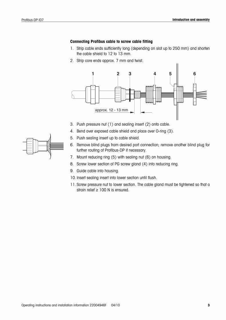
Connecting Profibus cable to screw cable fitting
1. Strip cable ends sufficiently long (depending on slot up to 250 mm) and shortenthe cable shield to 12 to 13 mm.
2. Strip core ends approx. 7 mm and twist.
3. Push pressure nut (1) and sealing insert (2) onto cable.
4. Bend over exposed cable shield and place over O-ring (3).
5. Push sealing insert up to cable shield.
6. Remove blind plugs from desired port connection; remove another blind plug forfurther routing of Profibus-DP if necessary.
7. Mount reducing ring (5) with sealing nut (6) on housing.
8. Screw lower section of PG screw gland (4) into reducing ring.
9. Guide cable into housing.
10. Insert sealing insert into lower section until flush.
11. Screw pressure nut to lower section. The cable gland must be tightened so that astrain relief ≥ 100 N is ensured.
Introduction and assembly
4 Operating instructions and installation information 22004946F 04/10
Profibus-DP-ID7
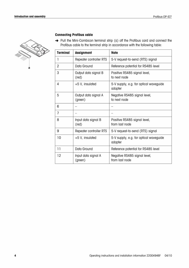
Connecting Profibus cable
➜ Pull the Mini-Combicon terminal strip (a) off the Profibus card and connect theProfibus cable to the terminal strip in accordance with the following table:
Terminal Assignment Note
1 Repeater controller RTS 5-V request-to-send (RTS) signal
2 Data Ground Reference potential for RS485 level
3 Output data signal B (red)
Positive RS485 signal level, to next node
4 +5 V, insulated 5-V supply, e.g. for optical waveguide adapter
5 Output data signal A (green)
Negative RS485 signal level, to next node
6 – –
7 – –
8 Input data signal B (red)
Positive RS485 signal level, from last node
9 Repeater controller RTS 5-V request-to-send (RTS) signal
10 +5 V, insulated 5-V supply, e.g. for optical waveguide adapter
11 Data Ground Reference potential for RS485 level
12 Input data signal A (green)
Negative RS485 signal level, from last node
Introduction and assembly
Operating instructions and installation information 22004946F 04/10 5
Profibus-DP-ID7
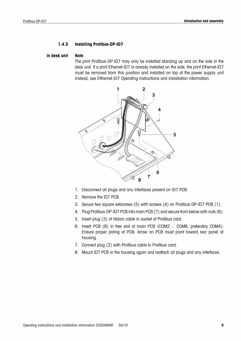
1.4.3 Installing Profibus-DP-ID7
in desk unit NoteThe print Profibus-DP-ID7 may only be installed standing up and on the side in thedesk unit. If a print Ethernet-ID7 is already installed on the side, the print Ethernet-ID7must be removed from this position and installed on top of the power supply unitinstead, see Etthernet-ID7 Operating instructions and installation information.
1. Disconnect all plugs and any interfaces present on ID7 PCB.
2. Remove the ID7 PCB.
3. Secure two square setscrews (5) with screws (4) on Profibus-DP-ID7 PCB (1).
4. Plug Profibus-DP-ID7 PCB into main PCB (7) and secure from below with nuts (6).
5. Insert plug (3) of ribbon cable in socket of Profibus card.
6. Insert PCB (8) in free slot of main PCB (COM2 ... COM6, preferably COM4).Ensure proper poling of PCB: Arrow on PCB must point toward rear panel ofhousing.
7. Connect plug (2) with Profibus cable to Profibus card.
8. Mount ID7 PCB in the housing again and reattach all plugs and any interfaces.
Introduction and assembly
6 Operating instructions and installation information 22004946F 04/10
Profibus-DP-ID7
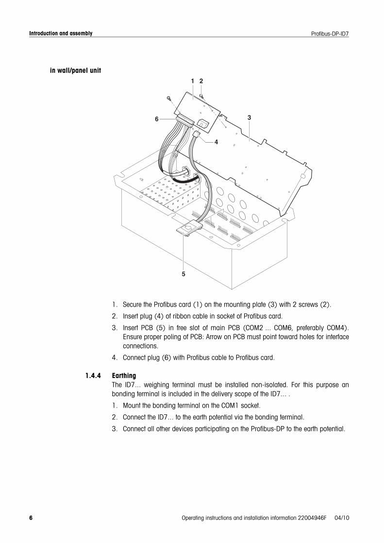
in wall/panel unit
1. Secure the Profibus card (1) on the mounting plate (3) with 2 screws (2).
2. Insert plug (4) of ribbon cable in socket of Profibus card.
3. Insert PCB (5) in free slot of main PCB (COM2 ... COM6, preferably COM4).Ensure proper poling of PCB: Arrow on PCB must point toward holes for interfaceconnections.
4. Connect plug (6) with Profibus cable to Profibus card.
1.4.4 EarthingThe ID7... weighing terminal must be installed non-isolated. For this purpose anbonding terminal is included in the delivery scope of the ID7... .
1. Mount the bonding terminal on the COM1 socket.
2. Connect the ID7... to the earth potential via the bonding terminal.
3. Connect all other devices participating on the Profibus-DP to the earth potential.
Introduction and assembly
Operating instructions and installation information 22004946F 04/10 7
Profibus-DP-ID7
1.4.5 Diagnostic LEDsThe 4 diagnostic LEDs on the Profibus-DP-ID7 interface output the following states:
Yellow LED Operating voltage switched on
Green LED Profibus data cycles started
Red LED Communication dialog faulty
Green LED Sign of activity in secondary cycle
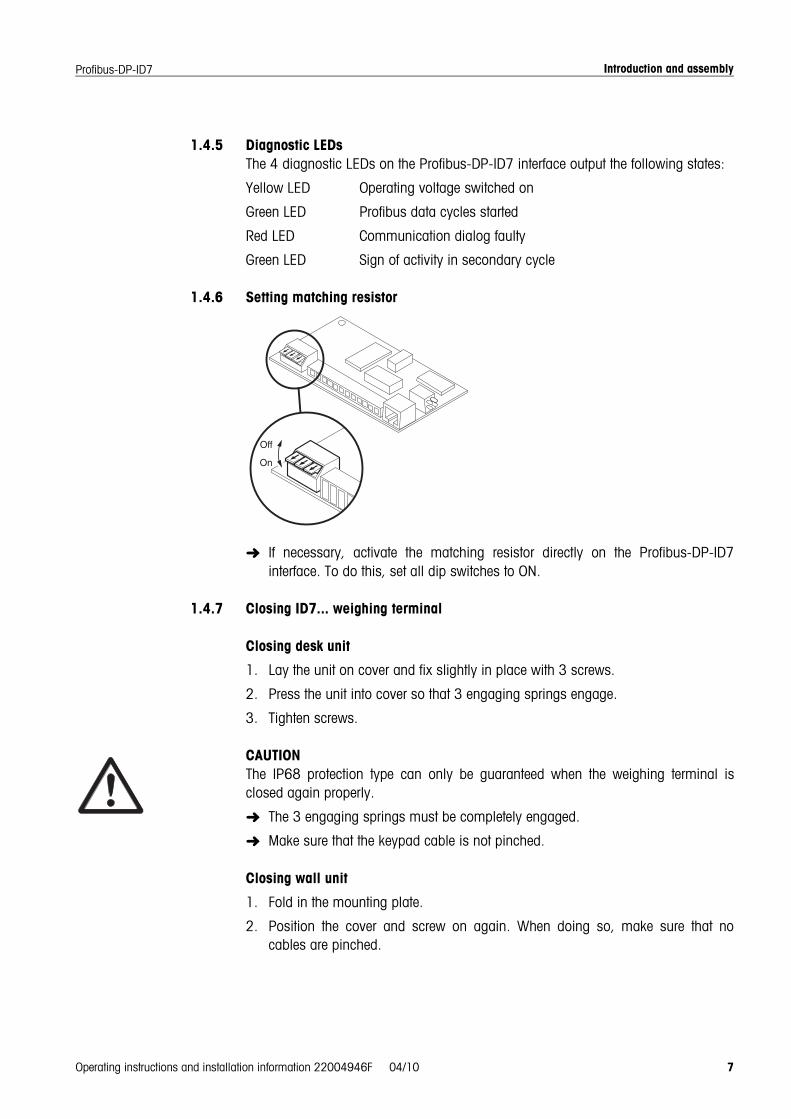
1.4.6 Setting matching resistor
➜ If necessary, activate the matching resistor directly on the Profibus-DP-ID7interface. To do this, set all dip switches to ON.
1.4.7 Closing ID7... weighing terminal
Closing desk unit
1. Lay the unit on cover and fix slightly in place with 3 screws.
2. Press the unit into cover so that 3 engaging springs engage.
3. Tighten screws.
CAUTIONThe IP68 protection type can only be guaranteed when the weighing terminal isclosed again properly.
➜ The 3 engaging springs must be completely engaged.
➜ Make sure that the keypad cable is not pinched.
Closing wall unit
1. Fold in the mounting plate.
2. Position the cover and screw on again. When doing so, make sure that nocables are pinched.

Introduction and assembly
8 Operating instructions and installation information 22004946F 04/10
Profibus-DP-ID7
Closing panel unit
1. Fold in the mounting plate and position the cover on the cut-out again.
2. Secure the cover on the switch cabinet from the inside with 10 screws. Whendoing so, make sure that no cables are pinched.

Settings in the master mode
Operating instructions and installation information 22004946F 04/10 9
Profibus-DP-ID7
2 Settings in master mode
2.1 Master mode block INTERFACE
Select interfaceconnection
➜ Select the interface connection in the first block.
Select interface setting ➜ Select the setting PROFIBUS-DP for the selected interface connection.If this setting is not offered, hardware and/or software must be updated on theweighing terminal. Please contact the METTLER TOLEDO Service for this purpose.
2.1.1 Configuring Profibus-DP-ID7
PROFIBUS-DP Configuring Profibus-DP-ID7
NODE ADDRESS Select desired node address in range 001 to 126.Factory setting: 126
OPERATING MODE Set type and word length of user data parameter VALUE.
16-BIT-INTEGER / 2 WORDS
Consistent over valid module pair in GSD file2 words 16-BIT-INTEGER 2(+2)W AI
16-BIT-INTEGER 2(+2)W AO
16-BIT-INTEGER / 4 WORDS
2 words 16-BIT-INTEGER 2(+2)W AI (use 2x)16-BIT-INTEGER 2(+2)W AO (use 2x)
32-BIT-FLOATING-POINT
4 words 32-BIT-FLOATING-POINT 4W AI32-BIT-FLOATING-POINT 4W AO
SETPOINT MODE Set type and use of setpoint.
UNIVERSAL Each setpoint can be set and read independently of others.
CHECKWEIGHING As soon as setpoints 1 and 2 are set, DeltaTrac CHECKWEIGHING will be activatedwith SP1 = setpoint and SP2 = tolerance (in %, in 16-bit integer mode with 2decimal places).In read table current state BELOW (SP1), GOOD (SP2) or ABOVE (SP3) can be readoff.
FILLING As soon as setpoints 1 and 2 are set, DeltaTrac CHECKWEIGHING will be activatedwith SP1 = setpoint and SP2 = tolerance (in %, in 16-bit integer mode with 2decimal places). In addition, SP3 and SP4 can also be loaded as any desiredsetpoints.In read table current state GOOD (SP1), ABOVE (SP2), SP3 REACHED (SP3) or SP4REACHED (SP4) can be read off.
Settings in the master mode
10 Operating instructions and installation information 22004946F 04/10
Profibus-DP-ID7
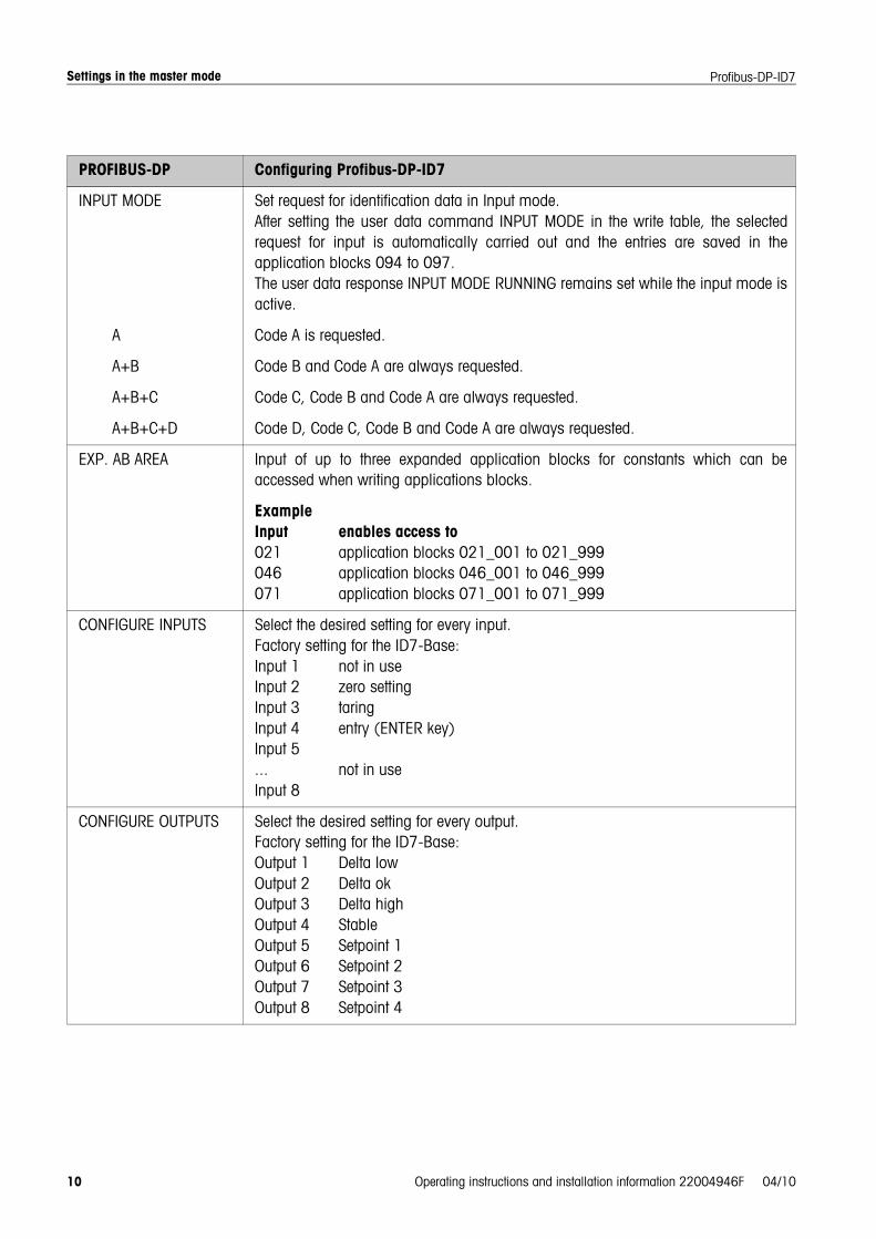
INPUT MODE Set request for identification data in Input mode.After setting the user data command INPUT MODE in the write table, the selectedrequest for input is automatically carried out and the entries are saved in theapplication blocks 094 to 097.The user data response INPUT MODE RUNNING remains set while the input mode isactive.
A Code A is requested.
A+B Code B and Code A are always requested.
A+B+C Code C, Code B and Code A are always requested.
A+B+C+D Code D, Code C, Code B and Code A are always requested.
EXP. AB AREA Input of up to three expanded application blocks for constants which can beaccessed when writing applications blocks.
ExampleInput enables access to021 application blocks 021_001 to 021_999046 application blocks 046_001 to 046_999071 application blocks 071_001 to 071_999
CONFIGURE INPUTS Select the desired setting for every input.Factory setting for the ID7-Base:Input 1 not in useInput 2 zero settingInput 3 taringInput 4 entry (ENTER key)Input 5... not in useInput 8
CONFIGURE OUTPUTS Select the desired setting for every output.Factory setting for the ID7-Base:Output 1 Delta lowOutput 2 Delta okOutput 3 Delta highOutput 4 StableOutput 5 Setpoint 1Output 6 Setpoint 2Output 7 Setpoint 3Output 8 Setpoint 4
PROFIBUS-DP Configuring Profibus-DP-ID7
Settings in the master mode
Operating instructions and installation information 22004946F 04/10 11
Profibus-DP-ID7
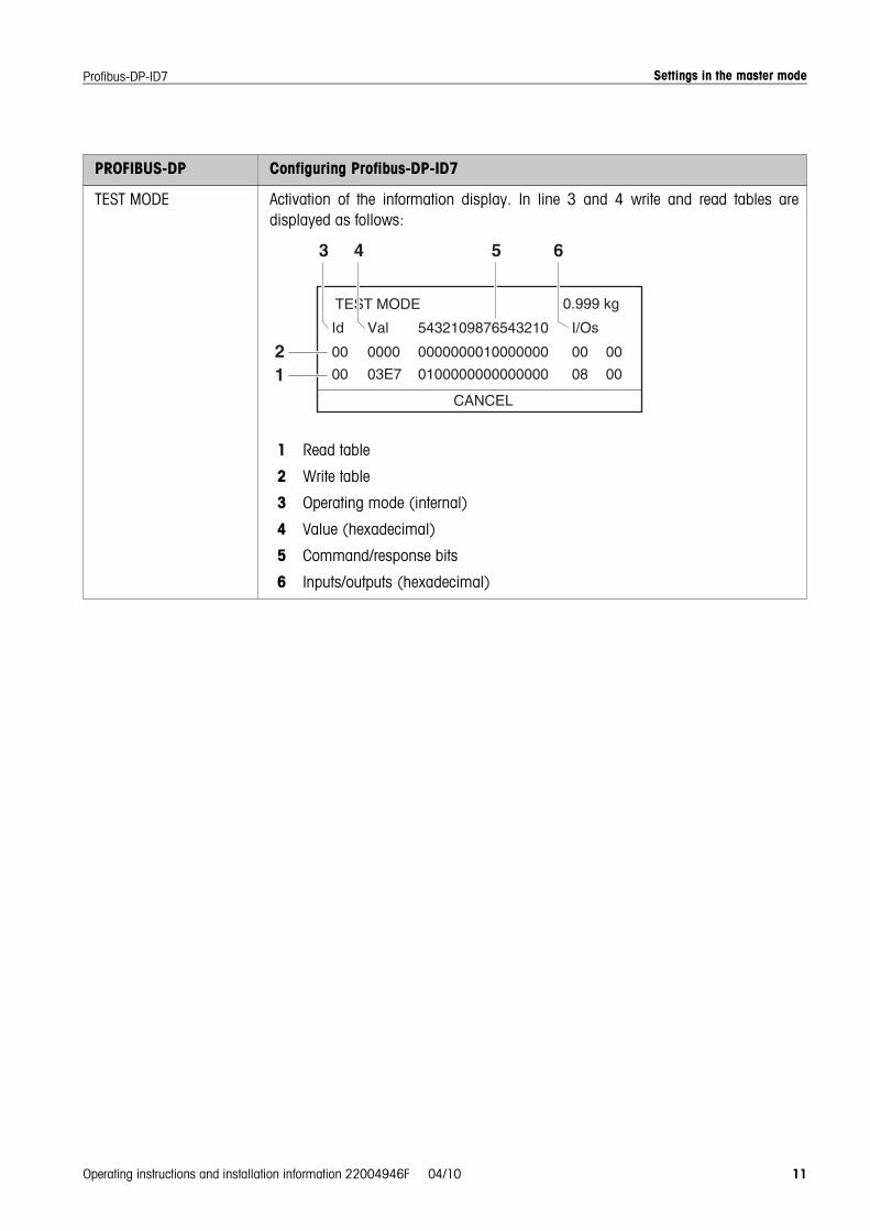
TEST MODE Activation of the information display. In line 3 and 4 write and read tables aredisplayed as follows:
1 Read table
2 Write table
3 Operating mode (internal)
4 Value (hexadecimal)
5 Command/response bits
6 Inputs/outputs (hexadecimal)
PROFIBUS-DP Configuring Profibus-DP-ID7
Interface description
12 Operating instructions and installation information 22004946F 04/10
Profibus-DP-ID7
3 Interface description
3.1 Profibus-DP communication with a PLC
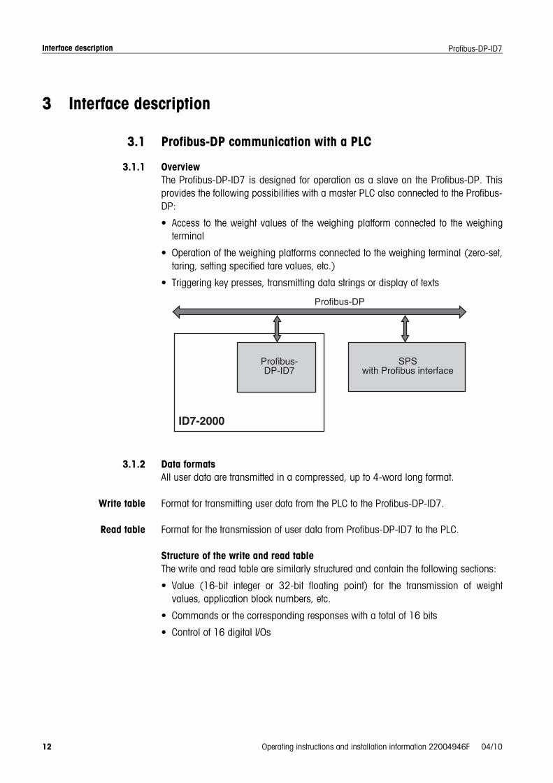
3.1.1 OverviewThe Profibus-DP-ID7 is designed for operation as a slave on the Profibus-DP. Thisprovides the following possibilities with a master PLC also connected to the Profibus-DP:
• Access to the weight values of the weighing platform connected to the weighingterminal
• Operation of the weighing platforms connected to the weighing terminal (zero-set,taring, setting specified tare values, etc.)
• Triggering key presses, transmitting data strings or display of texts
3.1.2 Data formatsAll user data are transmitted in a compressed, up to 4-word long format.
Write table Format for transmitting user data from the PLC to the Profibus-DP-ID7.
Read table Format for the transmission of user data from Profibus-DP-ID7 to the PLC.
Structure of the write and read tableThe write and read table are similarly structured and contain the following sections:
• Value (16-bit integer or 32-bit floating point) for the transmission of weightvalues, application block numbers, etc.
• Commands or the corresponding responses with a total of 16 bits
• Control of 16 digital I/Os
Interface description
Operating instructions and installation information 22004946F 04/10 13
Profibus-DP-ID7
3.1.3 HandshakeAs certain commands can not always be executed immediately by the scale, e.g.taring with a restless weighing platform, 3 handshake bits of the PLC allow clearmonitoring of the success of its commands:
1. The PLC starts a command by setting the corresponding command bit and alsotoggles COMMAND VALID in the write table. All other command bits are 0.
2. The weighing terminal responds with the current data of the read table. If it waspossible to completely process the command, the COMMAND EXECUTED bit istoggled. Otherwise COMMAND EXECUTED remains unchanged.
3. The PLC recognises whether it can transmit the next command or must repeat thelast one from COMMAND EXECUTED and transmits the write table to the weighingterminal.
4. The weighing terminal recognises from the status change of the COMMANDVALID bit that it should carry out the next command. In addition, the weighingterminal also detects whether the last command has been executed or is stillrunning. If the PLC attempts to start new commands before the previous one hasbeen confirmed by the weighing terminal with a status change of COMMANDVALID, the weighing terminal ignores this new command.
Interface description
14 Operating instructions and installation information 22004946F 04/10
Profibus-DP-ID7
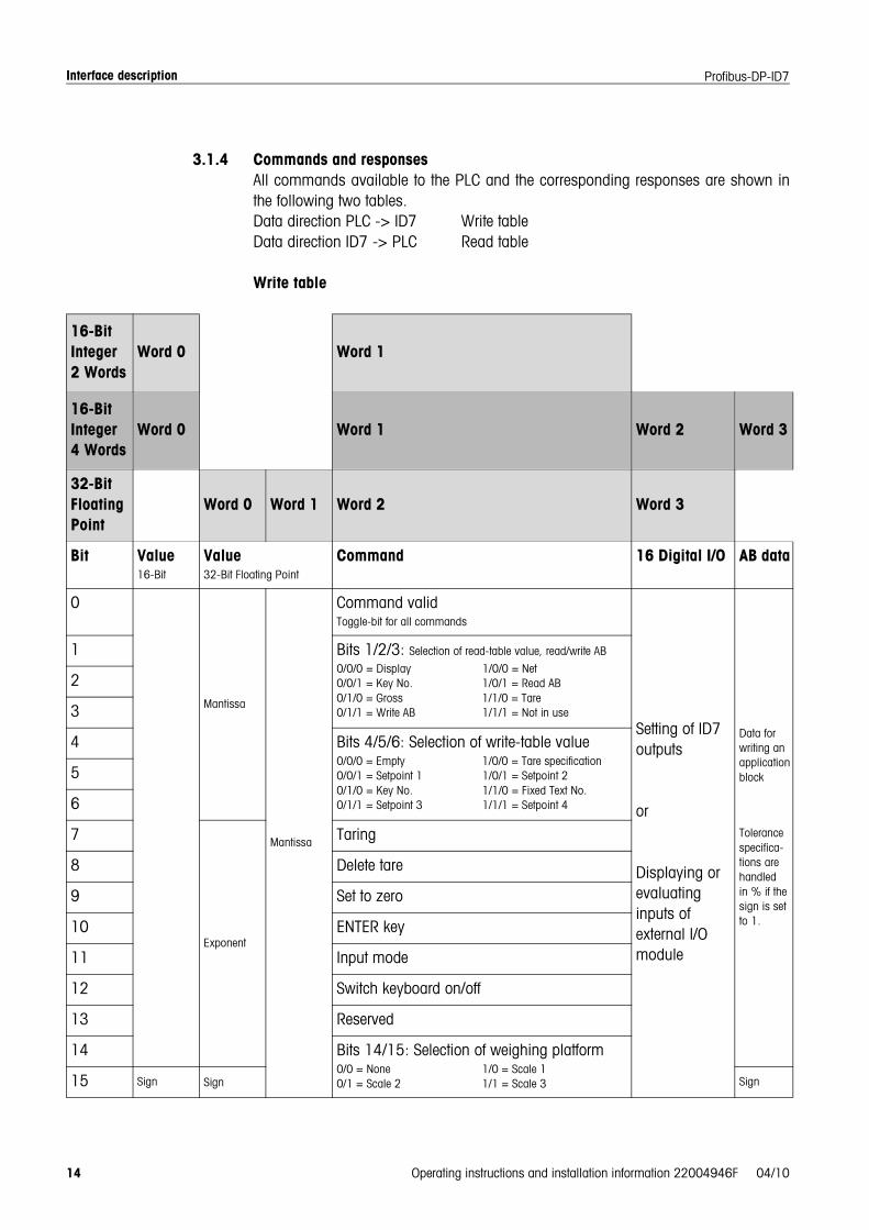
3.1.4 Commands and responsesAll commands available to the PLC and the corresponding responses are shown inthe following two tables. Data direction PLC -> ID7 Write table Data direction ID7 -> PLC Read table
Write table
16-Bit Integer2 Words
Word 0 Word 1
16-Bit Integer4 Words
Word 0 Word 1 Word 2 Word 3
32-BitFloatingPoint
Word 0 Word 1 Word 2 Word 3
Bit Value 16-Bit
Value 32-Bit Floating Point
Command 16 Digital I/O AB data
0
Mantissa
Mantissa
Command validToggle-bit for all commands
Setting of ID7 outputs
or
Displaying or evaluating inputs of external I/O module
Data for writing an applicationblock
Tolerance specifica-tions are handled in % if the sign is set to 1.
1 Bits 1/2/3: Selection of read-table value, read/write AB
0/0/0 = Display 1/0/0 = Net0/0/1 = Key No. 1/0/1 = Read AB0/1/0 = Gross 1/1/0 = Tare0/1/1 = Write AB 1/1/1 = Not in use
2
3
4 Bits 4/5/6: Selection of write-table value0/0/0 = Empty 1/0/0 = Tare specification0/0/1 = Setpoint 1 1/0/1 = Setpoint 20/1/0 = Key No. 1/1/0 = Fixed Text No.0/1/1 = Setpoint 3 1/1/1 = Setpoint 4
5
6
7
Exponent
Taring
8 Delete tare
9 Set to zero
10 ENTER key
11 Input mode
12 Switch keyboard on/off
13 Reserved
14 Bits 14/15: Selection of weighing platform0/0 = None 1/0 = Scale 10/1 = Scale 2 1/1 = Scale 315 Sign Sign Sign

Interface description
Operating instructions and installation information 22004946F 04/10 15
Profibus-DP-ID7
Read table
Notes on commandsIf the command requires parameters, they will be transmitted either as an integervalue or as a floating point value depending on the operating mode set. Exception: The commands READ/WRITE APPLICATION BLOCK and PRESS KEYalways expect integer values as parameters.
16-Bit Integer2 words
Word 0 Word 1
16-Bit Integer4 words
Word 0 Word 1 Word 2 Word 3
32-BitFloatingPoint
Word 0 Word 1 Word 2 Word 3
Bit Value 16-Bit
Value 32-Bit Floating Point
Command 16 Digital I/O Not in Use
0
Mantissa
Mantissa
Command executedToggle-bit for all commands
Showing or reading of ID7 inputs
or
Displaying or setting outputs of external I/O module
1 Error command
2 Movement
3 Net
4 Error scale (overload/underload...)
5 Key(s) was/were pressed
6 Input mode active
7
Exponent
Setpoint 1 reached
8 Setpoint 2 reached
9 Setpoint 3 reached
10 Setpoint 4 reached
11 1 = keyboard blocked, 0 = keyboard unblocked
12 Reserved
13 Reserved
14 Bits 14/15: Current weighing platform0/0 = None 1/0 = Scale 10/1 = Scale 2 1/1 = Scale 315 Sign Sign

Interface description
16 Operating instructions and installation information 22004946F 04/10
Profibus-DP-ID7
Read commands • The read commands Display value, Net, Gross, Tare, Key and Application blockoverwrite the cyclically transmitted display values with the required data. The dataare transmitted as 16-bit integers or 32-bit floating points. As soon as theCOMMAND EXECUTED bit is toggled, these values must be evaluated immediatelyby the PLC, as in the next cycle the value in the read table is overwritten again withthe current weight value.
• The response to the READ KEY NUMBER command (write table bits 1/2/3 = 0/0/1)is transmitted in the Word 0 (16-bit integer) or in Word 1 (32-bit floating point).The low byte contains the keyboard code, the high byte the function key code. The ID7 can store a maximum of 10 keys for being called via the READ KEYNUMBER command. If they are not called, the oldest key actuations areoverwritten.After reading out the last stored key, the KEY WAS PRESSED bit is reset. The keymemory is cleared after the device is switched on and after the mastermode isexited.
Reading and writingapplication blocks
• When writing an application block, the desired data are simultaneously transferredwith Word 3. For this reason, writing application blocks is only possible in 16-bitinteger/4-word mode.
• Only application blocks with the formats "numeric" or "weight value" can be reador written. When writing, certain tolerance (sub-)blocks (e.g. with DeltaTrac) canbe intentionally written with the format "percent" by setting the sign to "1".
• If a non-existent block or an alphanumeric block is selected, the ID7 responds withERROR COMMAND.The requested data are supplied in the 16-bit integer mode in the same format asthe weight value, and in the 32-bit floating point mode floating point values arealways transmitted.
The application block number in the write table must be entered as a value (Word 0in 16-bit integer mode, Word 1 in 32-bit floating point mode) in the following formatfor the READ APPLICATION BLOCK and WRITE APPLICATION BLOCK commands:
"Basic" application block
Sub-block no. Exp. Application block number
BitExample
15S
14S
13S
12S
11E
10E
9A
8A
7A
6A
5A
4A
3A
2A
1A
0A
AB 10 0 0 0 0 0 0 0 0 0 0 0 0 1 0 1 0
AB 20, sub-block 2 0 0 1 0 0 0 0 0 0 0 0 1 0 1 0 0
Interface description
Operating instructions and installation information 22004946F 04/10 17
Profibus-DP-ID7
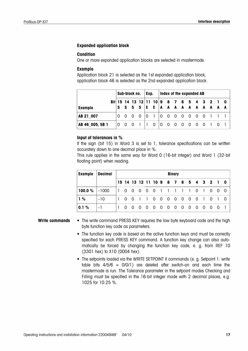
Expanded application block
ConditionOne or more expanded application blocks are selected in mastermode.
ExampleApplication block 21 is selected as the 1st expanded application block,application block 46 is selected as the 2nd expanded application block.
Input of tolerances in %If the sign (bit 15) in Word 3 is set to 1, tolerance specifications can be writtenaccurately down to one decimal place in %. This rule applies in the same way for Word 0 (16-bit integer) and Word 1 (32-bitfloating point) when reading.
Write commands • The write command PRESS KEY requires the low byte keyboard code and the highbyte function key code as parameters.
• The function key code is based on the active function keys and must be correctlyspecified for each PRESS KEY command. A function key change can also auto-matically be forced by changing the function key code, e. g. from REF 10(3301 hex) to X10 (0004 hex).
• The setpoints loaded via the WRITE SETPOINT X commands (e. g. Setpoint 1: writetable bits 4/5/6 = 0/0/1) are deleted after switch-on and each time themastermode is run. The Tolerance parameter in the setpoint modes Checking andFilling must be specified in the 16-bit integer mode with 2 decimal places, e.g.1025 for 10.25 %.
Sub-block no. Exp. Index of the expanded AB
BitExample
15S
14S
13S
12S
11E
10E
9A
8A
7A
6A
5A
4A
3A
2A
1A
0A
AB 21_007 0 0 0 0 0 1 0 0 0 0 0 0 0 1 1 1
AB 46_005, SB 1 0 0 0 1 1 0 0 0 0 0 0 0 0 1 0 1
Example Decimal Binary
15 14 13 12 11 10 9 8 7 6 5 4 3 2 1 0
100.0 % –1000 1 0 0 0 0 0 1 1 1 1 1 0 1 0 0 0
1 % –10 1 0 0 1 1 0 0 0 0 0 0 0 1 0 1 0
0.1 % –1 1 0 0 0 0 0 0 0 0 0 0 0 0 0 0 1

Interface description
18 Operating instructions and installation information 22004946F 04/10
Profibus-DP-ID7
Keyboard codes
Function key codes
* Only when the Pac is equipped with more than one function key page, i.e. morethan 6 function keys.
Key Code – Dec Code – Hex Key Code – Dec Code – Hex
Function key F1 1 01 Set to zero 14 0E
Function key F2 2 02 Taring 15 0F
Function key F3 3 03 Tare specification 16 10
Function key F4 4 04 Enter 17 11
Function key F5 5 05 Clear 18 12
Function key F6 6 06 ON/OFF 20 14
CODE A 7 07 +/– 31 1F
CODE B 8 08 . (Decimal) 46 2E
CODE C 9 09 Number key 0 48 30
CODE D 10 0A Number key 1 49 31
Function change 11 0B ... ...
Info 12 0C Number key 9 57 39
Scale 13 0D
Function key Code – Dec Code – Hex
Standard keys of ID7-Base 00 00
Extended tare keys of ID7-Base 02 02
Standard keys of Pac 51 33
Extended keys of Pac * 52 34
etc. * ... ...
Interface description
Operating instructions and installation information 22004946F 04/10 19
Profibus-DP-ID7
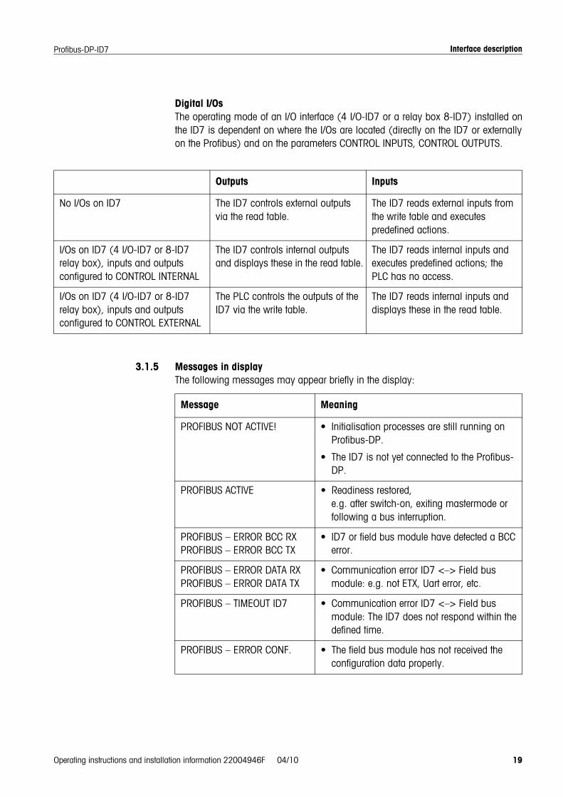
Digital I/OsThe operating mode of an I/O interface (4 I/O-ID7 or a relay box 8-ID7) installed onthe ID7 is dependent on where the I/Os are located (directly on the ID7 or externallyon the Profibus) and on the parameters CONTROL INPUTS, CONTROL OUTPUTS.
3.1.5 Messages in displayThe following messages may appear briefly in the display:
Outputs Inputs
No I/Os on ID7 The ID7 controls external outputs via the read table.
The ID7 reads external inputs from the write table and executes predefined actions.
I/Os on ID7 (4 I/O-ID7 or 8-ID7 relay box), inputs and outputs configured to CONTROL INTERNAL
The ID7 controls internal outputs and displays these in the read table.
The ID7 reads internal inputs and executes predefined actions; the PLC has no access.
I/Os on ID7 (4 I/O-ID7 or 8-ID7 relay box), inputs and outputs configured to CONTROL EXTERNAL
The PLC controls the outputs of the ID7 via the write table.
The ID7 reads internal inputs and displays these in the read table.
Message Meaning
PROFIBUS NOT ACTIVE! • Initialisation processes are still running on Profibus-DP.
• The ID7 is not yet connected to the Profibus-DP.
PROFIBUS ACTIVE • Readiness restored, e.g. after switch-on, exiting mastermode or following a bus interruption.
PROFIBUS – ERROR BCC RXPROFIBUS – ERROR BCC TX
• ID7 or field bus module have detected a BCC error.
PROFIBUS – ERROR DATA RXPROFIBUS – ERROR DATA TX
• Communication error ID7 <–> Field bus module: e.g. not ETX, Uart error, etc.
PROFIBUS – TIMEOUT ID7 • Communication error ID7 <–> Field bus module: The ID7 does not respond within the defined time.
PROFIBUS – ERROR CONF. • The field bus module has not received the configuration data properly.

Interface description
20 Operating instructions and installation information 22004946F 04/10
Profibus-DP-ID7
3.1.6 GSD fileThe GSD file required for communication with the Profibus-DP-ID7 is available fromMETTLER TOLEDO Service or can be downloaded from the Profibus GSD Library athttp://www.profibus.com.
3.1.7 Profibus DP-ID7 demo kitFor a demonstration and test of all commands with a normal PC, ask METTLERTOLEDO Customer Service for the Profibus DP-ID7 demo kit.
Technical data
Operating instructions and installation information 22004946F 04/10 21
Profibus-DP-ID7
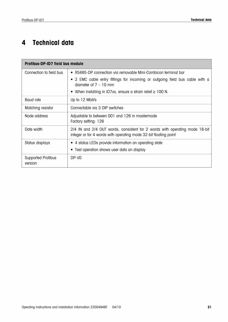
4 Technical data
Profibus-DP-ID7 field bus module
Connection to field bus • RS485-DP connection via removable Mini-Combicon terminal bar
• 2 EMC cable entry fittings for incoming or outgoing field bus cable with adiameter of 7 – 10 mm
• When installing in ID7xx, ensure a strain relief ≥ 100 N.
Baud rate Up to 12 Mbit/s
Matching resistor Connectable via 3 DIP switches
Node address Adjustable to between 001 and 126 in mastermodeFactory setting: 126
Date width 2/4 IN and 2/4 OUT words, consistent for 2 words with operating mode 16-bitinteger or for 4 words with operating mode 32-bit floating point
Status displays • 4 status LEDs provide information on operating state
• Test operation shows user data on display
Supported Profibus version
DP-V0

������� ���� 22004946F
Subject to technical changes © Mettler-Toledo (Albstadt) GmbH 04/10 Printed in Germany 22004946F
Mettler-Toledo (Albstadt) GmbHD-72458 AlbstadtTel. ++49-7431-14 0, Fax ++49-7431-14 232Internet: http://www.mt.com