operating instructions and parts manual 16-speed...
TRANSCRIPT

Operating Instructions and Parts Manual 16-speed Woodworking Drill Press Models JDP-15F, JDP-15B
JET 427 New Sanford Road LaVergne, Tennessee 37086 Part No. M-716250 Ph.: 800-274-6848 Edition 1 10/2015 www.jettools.com Copyright © 2015 JET
2
1.0 Warranty and Service JET® warrants every product it sells against manufacturers’ defects. If one of our tools needs service or repair, please contact Technical Service by calling 1-800-274-6846, 8AM to 5PM CST, Monday through Friday.
Warranty Period The general warranty lasts for the time period specified in the literature included with your product or on the official JET branded website.
• JET products carry a limited warranty which varies in duration based upon the product. (See chart below) • Accessories carry a limited warranty of one year from the date of receipt. • Consumable items are defined as expendable parts or accessories expected to become inoperable within a
reasonable amount of use and are covered by a 90 day limited warranty against manufacturer’s defects.
Who is Covered This warranty covers only the initial purchaser of the product from the date of delivery.
What is Covered This warranty covers any defects in workmanship or materials subject to the limitations stated below. This warranty does not cover failures due directly or indirectly to misuse, abuse, negligence or accidents, normal wear-and-tear, improper repair, alterations or lack of maintenance. JET woodworking machinery is designed to be used with Wood. Use of these machines in the processing of metal, plastics, or other materials outside recommended guidelines may void the warranty. The exceptions are acrylics and other natural items that are made specifically for wood turning.
Warranty Limitations Woodworking products with a Five Year Warranty that are used for commercial or industrial purposes default to a Two Year Warranty. Please contact Technical Service at 1-800-274-6846 for further clarification.
How to Get Technical Support Please contact Technical Service by calling 1-800-274-6846. Please note that you will be asked to provide proof of initial purchase when calling. If a product requires further inspection, the Technical Service representative will explain and assist with any additional action needed. JET has Authorized Service Centers located throughout the United States. For the name of an Authorized Service Center in your area call 1-800-274-6846 or use the Service Center Locator on the JET website.
More Information JET is constantly adding new products. For complete, up-to-date product information, check with your local distributor or visit the JET website.
How State Law Applies This warranty gives you specific legal rights, subject to applicable state law.
Limitations on This Warranty JET LIMITS ALL IMPLIED WARRANTIES TO THE PERIOD OF THE LIMITED WARRANTY FOR EACH PRODUCT. EXCEPT AS STATED HEREIN, ANY IMPLIED WARRANTIES OF MERCHANTABILITY AND FITNESS FOR A PARTICULAR PURPOSE ARE EXCLUDED. SOME STATES DO NOT ALLOW LIMITATIONS ON HOW LONG AN IMPLIED WARRANTY LASTS, SO THE ABOVE LIMITATION MAY NOT APPLY TO YOU. JET SHALL IN NO EVENT BE LIABLE FOR DEATH, INJURIES TO PERSONS OR PROPERTY, OR FOR INCIDENTAL, CONTINGENT, SPECIAL, OR CONSEQUENTIAL DAMAGES ARISING FROM THE USE OF OUR PRODUCTS. SOME STATES DO NOT ALLOW THE EXCLUSION OR LIMITATION OF INCIDENTAL OR CONSEQUENTIAL DAMAGES, SO THE ABOVE LIMITATION OR EXCLUSION MAY NOT APPLY TO YOU. JET sells through distributors only. The specifications listed in JET printed materials and on official JET website are given as general information and are not binding. JET reserves the right to effect at any time, without prior notice, those alterations to parts, fittings, and accessory equipment which they may deem necessary for any reason whatsoever. JET® branded products are not sold in Canada by JPW Industries, Inc.
Product Listing with Warranty Period 90 Days – Parts; Consumable items; Light-Duty Air Tools 1 Year – Motors; Machine Accessories; Heavy-Duty Air Tools; Pro-Duty Air Tools 2 Year – Metalworking Machinery; Electric Hoists, Electric Hoist Accessories; Woodworking Machinery used for industrial or commercial purposes 5 Year – Woodworking Machinery Limited Lifetime – JET Parallel clamps; VOLT Series Electric Hoists; Manual Hoists; Manual Hoist Accessories; Shop Tools; Warehouse & Dock products; Hand Tools
NOTE: JET is a division of JPW Industries, Inc. References in this document to JET also apply to JPW Industries, Inc., or any of its successors in interest to the JET brand.
3
2.0 Table of contents Section Page 1.0 Warranty and Service ..................................................................................................................................... 2 2.0 Table of contents ............................................................................................................................................ 3 3.0 IMPORTANT SAFETY INSTRUCTIONS ....................................................................................................... 4 4.0 About this manual .......................................................................................................................................... 5 5.0 Specifications ................................................................................................................................................. 6
5.1 Base mounting holes for JDP-15F/15B ...................................................................................................... 7 6.0 Setup and assembly ....................................................................................................................................... 8
6.1 Unpacking .................................................................................................................................................. 8 6.2 Shipping contents ....................................................................................................................................... 8 6.3 Additional tools required for assembly ....................................................................................................... 8 6.4 Location ...................................................................................................................................................... 9 6.5 Assembly .................................................................................................................................................... 9 6.6 Chuck key and wrench storage ................................................................................................................ 11
7.0 Electrical connections .................................................................................................................................. 11 7.1 Grounding instructions ............................................................................................................................. 11 7.2 Extension cords ........................................................................................................................................ 12
8.0 Adjustments ................................................................................................................................................. 12 8.1 Tools needed for adjustments .................................................................................................................. 12 8.2 Table movement ....................................................................................................................................... 12 8.3 Table insert leveling ................................................................................................................................. 13 8.4 Table slots ................................................................................................................................................ 13 8.5 Chuck and arbor removal ......................................................................................................................... 13 8.6 Installing bits ............................................................................................................................................. 13 8.7 Changing spindle speeds ......................................................................................................................... 14 8.8 Depth stop ................................................................................................................................................ 14 8.9 Quill retraction lock ................................................................................................................................... 15 8.10 Laser adjustment .................................................................................................................................... 15 8.11 LED work light ........................................................................................................................................ 16
9.0 Operating controls ........................................................................................................................................ 16 9.1 Control panel ............................................................................................................................................ 16 9.2 Safety key ................................................................................................................................................. 17
10.0 Operation ................................................................................................................................................... 17 10.1 Work piece positioning ........................................................................................................................... 17 10.2 General Inspection ................................................................................................................................. 17 10.3 Speed settings ........................................................................................................................................ 17
11.0 User-maintenance ...................................................................................................................................... 17 11.1 Belt replacement .................................................................................................................................... 18 11.2 Return spring .......................................................................................................................................... 18 11.3 Additional servicing ................................................................................................................................ 18
12.0 Speed chart ................................................................................................................................................ 19 13.0 Troubleshooting the JDP-15F/15B ............................................................................................................. 20 14.0 Replacement Parts ..................................................................................................................................... 20
14.1.1 JDP-15F Drill Press – Exploded View ................................................................................................. 21 14.1.2 JDP-15F Drill Press – Parts List .......................................................................................................... 22 14.1.1 JDP-15B Drill Press – Exploded View ................................................................................................. 26 14.1.2 JDP-15B Drill Press – Parts List .......................................................................................................... 27
15.0 Electrical Connections – JDP-15F/15B Drill Press ..................................................................................... 31
4
3.0 IMPORTANT SAFETY INSTRUCTIONS
When using an electrical appliance, basic precautions should always be followed, including the following:
READ ALL INSTRUCTIONS BEFORE USING THIS DRILL PRESS.
1. Read and understand the entire owner's manual before attempting assembly or operation.
2. Read and understand the warnings posted on the machine and in this manual. Failure to comply with all of these warnings may cause serious injury.
3. Replace the warning labels if they become obscured or removed.
4. This drill press is designed and intended for use by properly trained and experienced personnel only. If you are not familiar with the proper and safe operation of a drill press, do not use until proper training and knowledge have been obtained.
5. Do not use this drill press for other than its intended use. If used for other purposes, JET disclaims any real or implied warranty and holds itself harmless from any injury that may result from that use.
6. Always wear ANSI Z87.1 approved safety glasses or face shield while using this drum sander. (Everyday eyeglasses only have impact resistant lenses; they are not safety glasses.)
7. Before operating this drill press, remove tie, rings, watches and other jewelry, and roll sleeves up past the elbows. Remove all loose clothing and confine long hair. Non-slip footwear or anti-skid floor strips are recommended. Do not wear gloves.
8. Wear ear protectors (plugs or muffs) during extended periods of operation.
9. Some dust created by power sanding, sawing, grinding, drilling and other construction activities contain chemicals known to cause cancer, birth defects or other reproductive harm. Some examples of these chemicals are:
• Lead from lead based paint.
• Crystalline silica from bricks, cement and other masonry products.
• Arsenic and chromium from chemically treated lumber.
Your risk of exposure varies, depending on how often you do this type of work. To reduce your exposure to these chemicals, work in a well-ventilated area and work with approved safety equipment, such as face or dust masks that are specifically designed to filter out microscopic particles.
10. Do not operate this machine while tired or under the influence of drugs, alcohol or any medication.
11. Make certain the switch is in the OFF position before connecting the machine to the power supply.
12. Make certain the machine is properly grounded.
13. Make all machine adjustments or maintenance with the machine unplugged from the power source.
14. Remove adjusting keys and wrenches. Form a habit of checking to see that keys and adjusting wrenches are removed from the machine before turning it on.
15. Do not start the drill press while the cutting tool is in contact with the workpiece.
16. Secure workpiece firmly against table and make sure table is locked, before drilling.
17. Keep safety guards in place at all times when the machine is in use. If removed for maintenance purposes, use extreme caution and replace the guards immediately after completion of maintenance.
18. Check damaged parts. Before further use of the machine, a guard or other part that is damaged should be carefully checked to determine that it will operate properly and perform its intended function. Check for alignment of moving parts, binding of moving parts, breakage of parts, mounting and any other conditions that may affect its operation. A guard or other part that is damaged should be properly repaired or replaced.
19. Provide for adequate space surrounding work area and non-glare, overhead lighting.
20. Keep the floor around the machine clean and free of scrap material, oil and grease.
21. Keep visitors a safe distance from the work area. Keep children away.
22. Make your workshop child proof with padlocks, master switches or by removing starter keys.
23. Give your work undivided attention. Looking around, carrying on a conversation and “horse-play” are careless acts that can result in serious injury.
5
24. Maintain a balanced stance at all times so that you do not fall into the bit or other moving parts. Do not overreach or use excessive force to perform any machine operation.
25. Use the right tool at the correct speed and feed rate. Do not force a tool or attachment to do a job for which it was not designed. The right tool will do the job better and more safely.
26. Use recommended accessories; improper accessories may be hazardous.
27. Maintain tools with care. Keep tools sharp and clean for the best and safest performance. Follow instructions for lubricating, and changing accessories.
28. Turn off the machine before cleaning. Use a brush or compressed air to remove chips or debris — do not use your hands.
29. Do not stand on the machine. Serious injury could occur if the machine tips over.
30. Never leave the machine running unattended. Turn the power off and do not leave the machine until it comes to a complete stop.
31. Remove loose items and unnecessary work pieces from the area before starting the machine.
32. Don’t use in dangerous environment. Don’t use power tools in damp or wet location, or expose them to rain. Keep work area well lighted.
Familiarize yourself with the following safety notices used in this manual:
This means that if precautions are not heeded, it may result in minor injury and/or possible machine damage.
This means that if precautions are not heeded, it may result in serious, or possibly even fatal, injury.
4.0 About this manual This manual is provided by JET, covering the safe operation and maintenance procedures for a JET Model JDP-15F and JDP-15B Drill Press. This manual contains instructions on installation, safety precautions, general operating procedures, maintenance instructions and parts breakdown. Your machine has been designed and constructed to provide consistent, long-term operation if used in accordance with the instructions as set forth in this document.
This manual is not intended to be an exhaustive guide to drill press operational methods, use of jigs or after-market accessories, choice of bits or wood stock, etc. Additional knowledge can be obtained from experienced users or trade articles. Whatever accepted methods are used, always make personal safety a priority.
If there are questions or comments, please contact your local supplier or JET. JET can also be reached at our web site: www.jettools.com.
Retain this manual for future reference. If the machine transfers ownership, the manual should accompany it.
Read and understand the entire contents of this manual before attempting assembly or operation! Failure to comply may cause serious injury!
6
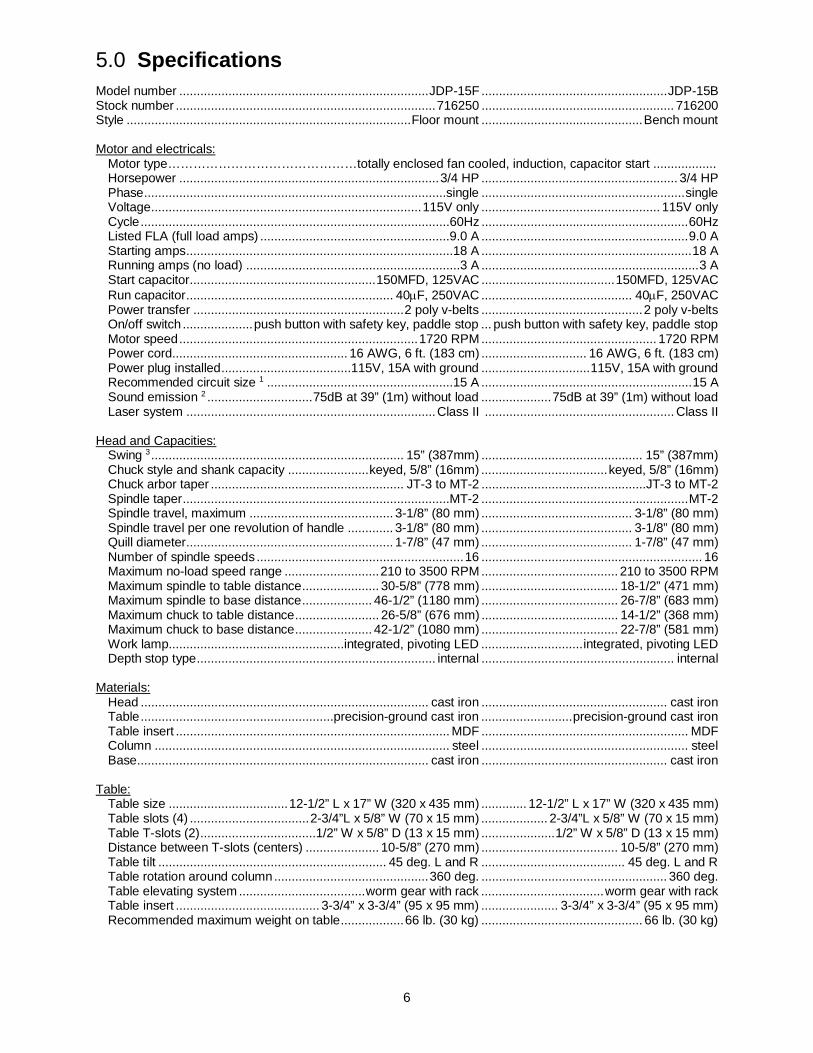
5.0 Specifications Model number ....................................................................... JDP-15F ..................................................... JDP-15B Stock number .......................................................................... 716250 ....................................................... 716200 Style ................................................................................. Floor mount .............................................. Bench mount Motor and electricals: Motor type………………………………………totally enclosed fan cooled, induction, capacitor start .................. Horsepower .......................................................................... 3/4 HP ........................................................ 3/4 HP Phase ......................................................................................single .......................................................... single Voltage ............................................................................. 115V only ................................................... 115V only Cycle ........................................................................................60Hz ........................................................... 60Hz Listed FLA (full load amps) ......................................................9.0 A ........................................................... 9.0 A Starting amps ............................................................................18 A ............................................................ 18 A Running amps (no load) .............................................................3 A .............................................................. 3 A Start capacitor ..................................................... 150MFD, 125VAC ...................................... 150MFD, 125VAC Run capacitor ........................................................... 40μF, 250VAC ........................................... 40μF, 250VAC Power transfer ............................................................ 2 poly v-belts .............................................. 2 poly v-belts On/off switch .................... push button with safety key, paddle stop ... push button with safety key, paddle stop Motor speed .................................................................... 1720 RPM .................................................. 1720 RPM Power cord .................................................. 16 AWG, 6 ft. (183 cm) .............................. 16 AWG, 6 ft. (183 cm) Power plug installed .....................................115V, 15A with ground ............................... 115V, 15A with ground Recommended circuit size 1 .....................................................15 A ............................................................ 15 A Sound emission 2 .............................. 75dB at 39” (1m) without load .................... 75dB at 39” (1m) without load Laser system ....................................................................... Class II ...................................................... Class II Head and Capacities: Swing 3 ........................................................................ 15” (387mm) .............................................. 15” (387mm) Chuck style and shank capacity ....................... keyed, 5/8” (16mm) .................................... keyed, 5/8” (16mm) Chuck arbor taper ....................................................... JT-3 to MT-2 ...............................................JT-3 to MT-2 Spindle taper ............................................................................MT-2 ........................................................... MT-2 Spindle travel, maximum ......................................... 3-1/8” (80 mm) ........................................... 3-1/8” (80 mm) Spindle travel per one revolution of handle ............. 3-1/8” (80 mm) ........................................... 3-1/8” (80 mm) Quill diameter ........................................................... 1-7/8” (47 mm) ........................................... 1-7/8” (47 mm) Number of spindle speeds ........................................................... 16 ............................................................... 16 Maximum no-load speed range ........................... 210 to 3500 RPM ....................................... 210 to 3500 RPM Maximum spindle to table distance ...................... 30-5/8” (778 mm) ....................................... 18-1/2” (471 mm) Maximum spindle to base distance .................... 46-1/2” (1180 mm) ....................................... 26-7/8” (683 mm) Maximum chuck to table distance ........................ 26-5/8” (676 mm) ....................................... 14-1/2” (368 mm) Maximum chuck to base distance ...................... 42-1/2” (1080 mm) ....................................... 22-7/8” (581 mm) Work lamp ..................................................integrated, pivoting LED ............................. integrated, pivoting LED Depth stop type .................................................................... internal ....................................................... internal Materials: Head .................................................................................. cast iron ..................................................... cast iron Table .......................................................precision-ground cast iron .......................... precision-ground cast iron Table insert .............................................................................. MDF ........................................................... MDF Column .................................................................................... steel ........................................................... steel Base ................................................................................... cast iron ..................................................... cast iron Table: Table size .................................. 12-1/2” L x 17” W (320 x 435 mm) ............. 12-1/2” L x 17” W (320 x 435 mm) Table slots (4) .................................. 2-3/4”L x 5/8” W (70 x 15 mm) ................... 2-3/4”L x 5/8” W (70 x 15 mm) Table T-slots (2) .................................1/2” W x 5/8” D (13 x 15 mm) ..................... 1/2” W x 5/8” D (13 x 15 mm) Distance between T-slots (centers) ..................... 10-5/8” (270 mm) ....................................... 10-5/8” (270 mm) Table tilt ................................................................. 45 deg. L and R ......................................... 45 deg. L and R Table rotation around column ............................................ 360 deg. ..................................................... 360 deg. Table elevating system .................................... worm gear with rack ................................... worm gear with rack Table insert ......................................... 3-3/4” x 3-3/4” (95 x 95 mm) ...................... 3-3/4” x 3-3/4” (95 x 95 mm) Recommended maximum weight on table .................. 66 lb. (30 kg) .............................................. 66 lb. (30 kg)
7
Base and Column: Base size ......................................... 18-7/8”L x 11-3/8”W x 2-5/8”H ..........................18”L x 11-3/8”W x 2-1/4”H ........................................................................ (480 x 288 x 66 mm) .................................. (460 x 288 x 56 mm) Base working surface ...................... 8”L x 9-1/2”W (200 x 240 mm) ................. 8” L x 9-1/2” W (200 x 240 mm) Base slots (2) ................................ 5/8”W x 6-5/16”L (16 x 160 mm) ................ 5/8”W x 6-5/16”L (16 x 160 mm) Distance between base slots (centers) ........................ 5” (126 mm) ............................................... 5” (126 mm) Column diameter ............................................ 2-7/8” (ø73 x T3mm) .................................. 2-7/8” (ø73 x T3mm) Dimensions and Weights: Overall dimensions, assembled ........... 26-5/8”L x 17”W x 63-7/8”H ....................... 26-5/8”L x 17”W x 43-7/8”H .................................................................... (677 x 434 x 1623 mm) .............................. (677 x 434 x 1115 mm) Shipping dimensions ...................... 58”L x 24-7/16”W x 12-13/16”H ................ 36-1/2”L x 33-1/4”W x 12-13/16” .................................................................... (1475 x 625 x 320 mm) ................................ (925 x 845 x 325 mm) Net weight (approximate) ........................................ 172 lb (78.2 kg) .......................................... 154 lb (70.2 kg) Shipping weight (approximate) ............................... 183 lb (83.2 kg) ....................................... 165.5 lb (75.2 kg) L = length; W = width; H = height 1 Subject to local and national electrical codes. 2 The specified values are emission levels and are not necessarily to be seen as safe operating levels. As workplace
conditions vary, this information is intended to allow the user to make a better estimation of the hazards and risks involved only.
3 Swing is twice the distance from column to spindle center (i.e., the maximum diameter of workpiece that can be drilled to its center).
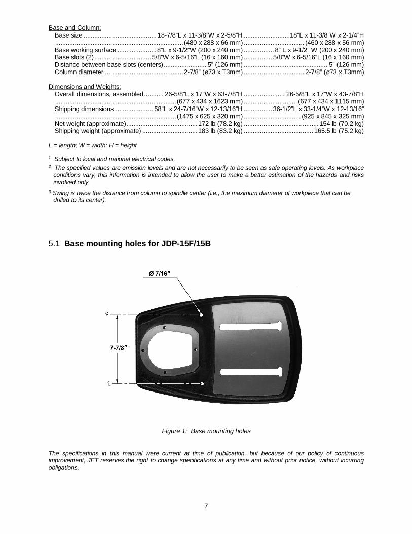
5.1 Base mounting holes for JDP-15F/15B
Figure 1: Base mounting holes
The specifications in this manual were current at time of publication, but because of our policy of continuous improvement, JET reserves the right to change specifications at any time and without prior notice, without incurring obligations.
8
6.0 Setup and assembly
Read and understand all assembly instructions before attempting assembly. Failure to comply may cause serious injury.
6.1 Unpacking Separate all parts from the packing material. Check each part against sect. 6.2 Shipping contents and make certain that all items are accounted for before discarding any packing material. Report any shortages or shipping damage to your JET distributor.
Exposed metal surfaces on the drill press have been factory-coated with a protectant. Remove this with a soft rag moistened with a light solvent, such as kerosene or WD-40®. Do not use an abrasive pad, and do not use gasoline, paint thinner or acetone – these will damage plastic components and painted surfaces.
After assembly, exposed metal surfaces on the drill press should be periodically coated with a light application of paste wax or other rust-protectant.
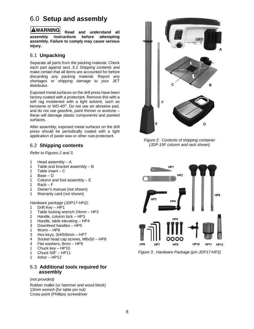
6.2 Shipping contents Refer to Figures 2 and 3. 1 Head assembly – A 1 Table and bracket assembly – B 1 Table insert – C 1 Base – D 1 Column and foot assembly – E 1 Rack – F 1 Owner’s manual (not shown) 1 Warranty card (not shown)
Hardware package (JDP17-HP2): 1 Drift Key – HP1 1 Table locking wrench 24mm – HP2 1 Handle, column lock – HP3 1 Handle, table elevating – HP4 3 Downfeed handles – HP5 1 Worm – HP6 3 Hex keys, 3/4/5/6mm – HP7 4 Socket head cap screws, M8x50 – HP8 4 Flat washers, 8mm – HP9 1 Chuck key – HP10 1 Chuck 5/8” – HP11 1 Arbor – HP12
6.3 Additional tools required for assembly
(not provided) Rubber mallet (or hammer and wood block) 13mm wrench (for table pin nut) Cross-point (Phillips) screwdriver
Figure 2: Contents of shipping container
(JDP-15F column and rack shown)
Figure 3: Hardware Package (p/n JDP17-HP2)
9
6.4 Location The drill press should be placed in a dry area, with a level floor and good lighting. Provide enough space around drill press to allow for operations and any adjustments or servicing.
6.5 Assembly
Do not connect drill press to power source until machine has been fully assembled.
1. Place the base upon a level floor. It may be secured to the floor with lag screws (not provided) through the two holes in the base. Refer to Figure 1 for hole spacing.
If you do not wish permanent attachment to the floor, the drill press can be bolted to a plywood panel which will serve as an expanded base and further stabilize the machine. Use a high grade of plywood (not particle board) at least 3/4" thick. It should be large enough to prevent vibration, sliding or moving of drill press during operation. Do not use a mobile base with this machine.
2. Make sure the set screw (Figure 4) is tight against the column. Tighten further if needed, using a 5mm hex key.
Figure 4
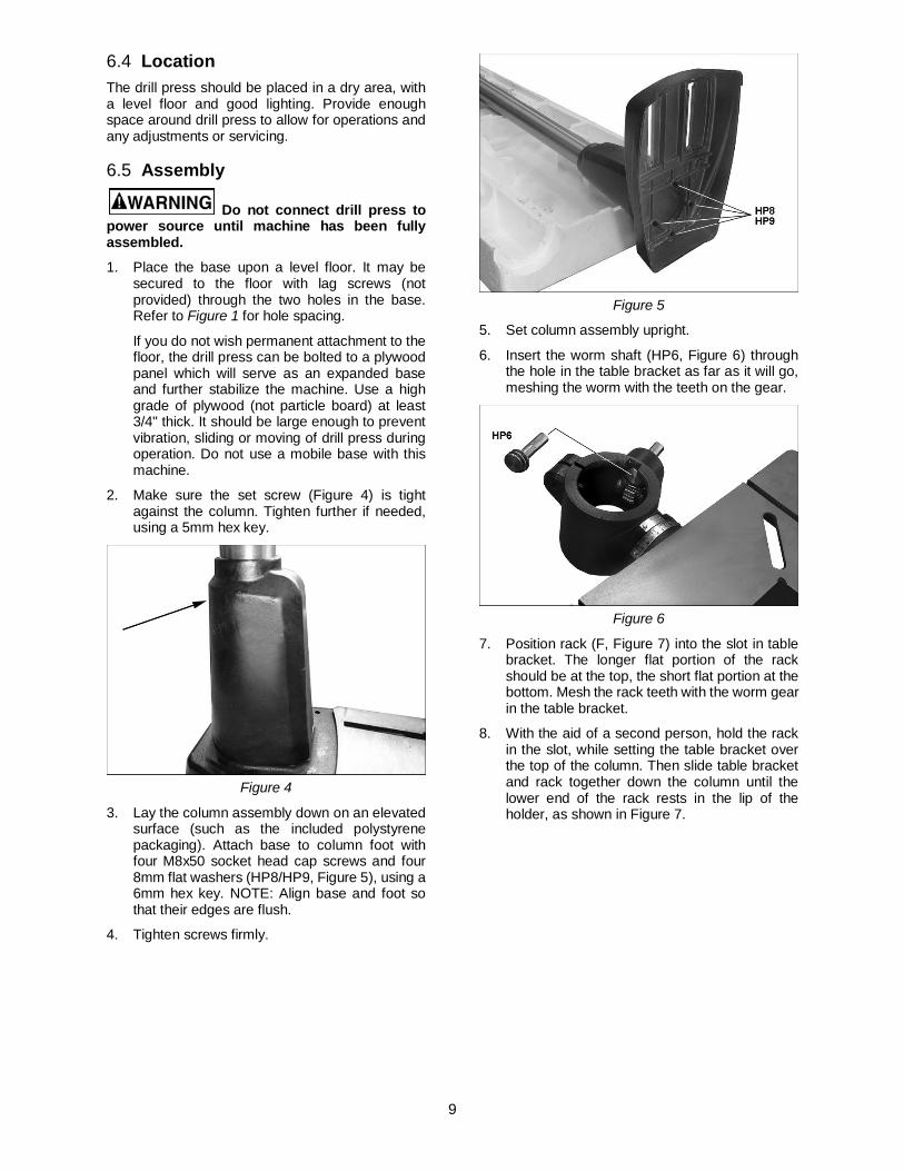
3. Lay the column assembly down on an elevated surface (such as the included polystyrene packaging). Attach base to column foot with four M8x50 socket head cap screws and four 8mm flat washers (HP8/HP9, Figure 5), using a 6mm hex key. NOTE: Align base and foot so that their edges are flush.
4. Tighten screws firmly.
Figure 5
5. Set column assembly upright.
6. Insert the worm shaft (HP6, Figure 6) through the hole in the table bracket as far as it will go, meshing the worm with the teeth on the gear.
Figure 6
7. Position rack (F, Figure 7) into the slot in table bracket. The longer flat portion of the rack should be at the top, the short flat portion at the bottom. Mesh the rack teeth with the worm gear in the table bracket.
8. With the aid of a second person, hold the rack in the slot, while setting the table bracket over the top of the column. Then slide table bracket and rack together down the column until the lower end of the rack rests in the lip of the holder, as shown in Figure 7.
10
Figure 7
9. Place stop collar (G, Figure 8) onto column and slide it down over top end of rack. Orient the stop collar so that chuck key holder (H) is in desired position around the column.
10. Tighten set screw (J) with a 4mm hex key.
11. Push chuck key into holder (inset, Figure 8)
Figure 8
12. Slide table elevating handle (HP4, Figure 9) onto protruding shaft of worm. Make sure the set screw in the handle aligns with the flat on the worm shaft.
13. Tighten set screw (K) in table elevating handle with 4mm hex key.
14. Mount column locking handle (HP3, Figure 9) to rear of table bracket. The quickest way to install this is to remove the handle by unscrewing the screw with its spring (L). Insert the bolt (N) into the table bracket hole, then reinstall handle (M), spring and screw (L).
Note: The locking handle (HP3) is adjustable. To reposition, pull out on the handle and rotate it, then release it, making sure it reseats itself on the bolt head.
Figure 9
The head assembly is heavy! To avoid injury and/or damage to equipment, lift the head onto the column only with additional assistance!
15. With the aid of a second person, carefully lift the head assembly and place it onto the column. Slide head down as far as it will go. Rotate head assembly until the sides of the belt cover are parallel with the sides of the base.
16. Tighten the two set screws (O, Figure 10) with a 5mm hex key until they are snug.
Figure 10
17. Install three downfeed handles (HP5, Figure 11) into hub by screwing them in completely. A flat is provided on each handle for a 9mm wrench or pliers to help tighten if needed.
Figure 11
18. Thoroughly clean spindle, arbor and chuck (Figure 12) with a soft rag and solvent, such as mineral spirits.
11
Important: These three pieces must be free of any rust protection, or lubricant. Any grease or residue in these areas can cause the pieces to separate, creating a safety hazard and potential damage to the tool.
Figure 12
19. Lower the table out of the way of the spindle area.
20. Slide arbor (HP12) up into spindle. Turn the arbor as you push it, until the tang engages the slot in the spindle.
21. Push chuck (HP11) onto arbor.
22. Twist the chuck to completely retract the chuck jaws if they are exposed.
23. Use a rubber mallet, or a steel hammer against a block of wood, to sharply tap the bottom of the chuck two or three times to seat the chuck/arbor assembly. Note: Do not use a steel faced hammer directly against the chuck.
6.6 Chuck key and wrench storage The chuck key can be stored in the clip on the collar (see Figure 8).
The table locking wrench has a magnetic disc attached, and can be stored on any metal surface.
Do not store in an area near the worktable, or where the wrench could vibrate off into moving parts.
7.0 Electrical connections
Electrical connections must be made by a qualified electrician in compliance with all relevant codes. This machine must be properly grounded to help prevent electrical shock and possible fatal injury.
The JDP-15F/15B drill press is rated at 115V power only, and comes with a plug designed for use on a circuit with a grounded outlet that looks like the one pictured in A, Figure 13.
Before connecting to power source, be sure the switch is in off position.
It is recommended that the drill press be connected to a dedicated 15 amp circuit with circuit breaker or fuse. If connected to a circuit protected by fuses, use time delay fuse marked “D”. Local codes take precedence over recommendations.
7.1 Grounding instructions This machine must be grounded. In the event of a malfunction or breakdown, grounding provides a path of least resistance for electric current to reduce the risk of electric shock. This tool is equipped with an electric cord having an equipment-grounding conductor and a grounding plug. The plug must be plugged into a matching outlet that is properly installed and grounded in accordance with all local codes and ordinances.
Do not modify the plug provided - if it will not fit the outlet, have the proper outlet installed by a qualified electrician.
Improper connection of the equipment-grounding conductor can result in a risk of electric shock. The conductor with insulation having an outer surface that is green with or without yellow stripes is the equipment-grounding conductor. If repair or replacement of the electric cord or plug is necessary, do not connect the equipment-grounding conductor to a live terminal.
Check with a qualified electrician or service personnel if the grounding instructions are not completely understood, or if in doubt as to whether the tool is properly grounded. Failure to comply may cause serious or fatal injury.
Use only 3-wire extension cords that have 3-prong grounding plugs and 3-pole receptacles that accept the tool's plug.
Repair or replace damaged or worn cord immediately.
This tool is for use on a nominal 120-V circuit, and has a grounded plug that looks like the plug illustrated in sketch A in Figure 13. A temporary adaptor that looks like the adaptor illustrated in sketches B and C may be used to connect this plug to a 2-pole receptacle as shown in sketch B if a properly grounded outlet is not available. The temporary adaptor should be used only until a properly grounded outlet (sketch A) can be installed by a qualified electrician. The green colored rigid ear, lug, or the like extending from the adaptor must be connected to a permanent ground such as a properly grounded outlet box cover. Whenever the adaptor is used, it must be held in place by a metal screw.
In Canada, the use of a temporary adaptor is not permitted by the Canadian Electrical Code, C22.1.
12
Figure 13
7.2 Extension cords The use of extension cords is discouraged; try to position equipment near the power source. If an extension cord becomes necessary, be sure to use one heavy enough to carry the current your product will draw. An undersized cord will cause a drop in line voltage resulting in loss of power and overheating. Table 1 shows correct size to use depending on cord length and nameplate ampere rating. If in doubt, use the next heavier gauge. The smaller the gauge number, the heavier the cord.
Ampere Rating Volts Total length of cord in feet
More Than
Not More Than
120 25 50 100 150
AWG
00 06 18 16 16 14 06 10 18 16 14 12 10 12 16 16 14 12
12 16 14 12 Not Recommended
Table 1: Extension Cord Recommendations
8.0 Adjustments
8.1 Tools needed for adjustments Pliers 13mm wrench 24mm wrench (provided) Rubber mallet
8.2 Table movement 8.2.1 Table raising and lowering
Refer to Figure 14.
Loosen column locking handle (A, Figure 14). Turn table elevating handle (B) to raise or lower table along column rack. Re-tighten locking handle (A) before attempting to drill.
Figure 14
8.2.2 Table repositioning
Refer to Figure 14.
When drilling into a long workpiece, swing table out of the way and use drill press base as your table. Slots in the base can be used to mount work holding devices.
1. Loosen column locking handle (A).
2. Swing table around the column. If rack (C) tends to bind, you will need to nudge the top or bottom end of the rack around the column while swinging table.
3. Tighten column locking handle (A).
8.2.3 Table tilting
Refer to Figure 15.
1. Turn nut (D) clockwise with 13mm wrench to extract the alignment pin (E). The alignment pin is tapered and will back out as the nut is turned.
2. Remove alignment pin.
3. Loosen hex cap screw (F), with provided 24mm wrench, and tilt table to desired angle using the angle scale.
4. Tighten the hex cap screw (F).
The alignment pin (E) only works at 90° and must be reinserted when the table is returned to 90°. Reinsert the alignment pin, along with the nut, and tap it lightly with a rubber mallet for full insertion.

13
Figure 15
8.3 Table insert leveling Refer to Figure 16.
The insert should be flush with the table surface:
1. Remove the two screws beneath table insert (G, Figure 16).
2. Loosen any of the wing nuts (H) and rotate the bolts (J) as needed until the insert is level with the table surface.
TIP: A straight edge clamped to the table and across the insert will facilitate correct leveling during this procedure.
3. Tighten all four wing nuts.
4. The two screws (G) may be reinstalled, if desired, to retain insert in position.
Figure 16
8.4 Table slots The table has four through-slots and two T-slots, for attaching clamps, fence, or other accessories.
8.5 Chuck and arbor removal Refer to Figure 17.
1. Disconnect machine from power source.
2. Lower the table to clear the chuck area.
4. Lower quill assembly with the downfeed handles to expose slot and lock it in the lowered position (see sect. 8.5, Quill retraction lock). While maintaining the lowered quill position, rotate spindle by hand to align the slot in the spindle with the slot in the quill.
5. Insert drift key (HP1) into the aligned slots and tap lightly. The chuck and arbor assembly should fall from the spindle.
Prepare to catch the chuck and arbor as it drops. Striking the floor could damage tool.
Figure 17
8.6 Installing bits The chuck accepts bits with a 5/8” or smaller shank.
1. Insert bit (not provided) into chuck jaws with about 1” insertion. When using a small bit, do not insert it so far that the jaws touch the flutes of the bit.
2. Make sure bit is centered in chuck before tightening chuck.
3. Turn chuck key clockwise to tighten chuck jaws. See Figure 18. NOTE: Insert chuck key into each of the three holes in the chuck and tighten to ensure tightness of each jaw.
4. The chuck key has a spring-loaded pin to prevent it being left in the chuck. However, always check the area and clear away any tools before starting the drill press.
5. Turn chuck key counterclockwise to loosen chuck jaws and remove bit.
14
Figure 18
8.7 Changing spindle speeds Refer to Figure 19.
1. Disconnect machine from power source.
2. Open belt cover. Loosen knob (A, Figure 19) and pull tensioner (B) away from belt to release tension.
3. Consult speed chart (C) and position belts accordingly.
Note: The center pulley can be pushed to front or back to release tension to either belt, as needed. When front belt is correctly positioned, push center pulley backward to tighten front belt and allow rear belt to slide onto the pulleys.
4. Make sure belts are properly seated in the grooves of each pulley.
5. Push tensioner (B) into belt and tighten knob (A). Close hood.
Figure 19
8.8 Depth stop The depth stop is used for repetitive drilling of holes of identical depth.
Depth stop can be established by one of two procedures:
Method #1:
Refer to Figures 20 and 21.
1. Loosen lock handle (G, Figure 21).
2. Use downfeed handles (D, Figure 21) to lower the bit until it just contacts the top surface of workpiece, as shown in Figure 20.
3. Hold downfeed handle in position, and rotate scale ring (E, Figure 21) to zero. This sets the workpiece surface as your zero reference point.
4. Move workpiece out from under bit, and rotate downfeed handle to lower bit until scale ring (E) reads your desired depth.
5. Hold downfeed handle in this position, and rotate lock ring (F) counterclockwise as far as it will turn. You should be able to feel and hear when the lock ring reaches the end of its rotation.
6. Tighten lock handle (G).
7. The bit can now be repeatedly lowered to the pre-set depth using the downfeed handles.
8. To release the depth stop, loosen lock handle (G).
Figure 20
Figure 21
Method #2:
Refer to Figures 22 and 23.
1. Mark the desired depth of cut on the side of the workpiece (Figure 22).
2. Use downfeed handle (D, Figure 23) to lower the bit to the mark. Hold downfeed handle in position.
3. Rotate lock ring (F) counterclockwise as far as it will turn. You should be able to feel and hear when the lock ring reaches the end of its rotation.
15
4. Tighten lock handle (G).
5. The bit will now stop at the marked depth when the downfeed handle is rotated.
6. To release the depth stop, loosen lock handle (G).
Figure 22
Figure 23
NOTE: Method #2 allows rapid, fine adjustment to the setting, as follows:
If the depth setting is found to be too shallow:
1. Hold downfeed handle (D) stationary while slightly loosening lock handle (G).
2. Slightly rotate downfeed handle to lower bit to the more accurate position.
3. Retighten lock handle (G). Depth is now set to more accurate position.
If the depth setting is found to be too deep:
1. Loosen lock handle (G) while holding downfeed handle stationary.
2. Slightly back off the lock ring (F), that is, rotate it clockwise.
3. Slightly rotate downfeed handle to bring bit up to more accurate depth.
4. Rotate lock ring (F) all the way counter-clockwise.
5. Tighten lock handle (G). Depth is now set to more accurate position.
8.9 Quill retraction lock The quill can be held in the down position and prevented from retracting, such as for operating a sanding drum or to facilitate removal of chuck and arbor.
To lock the quill in down position, proceed as follows (Figure 24):
1. Loosen lock handle (G, Figure 24).
2. Rotate downfeed handle (D) to lower spindle to the point at which it is to be locked, and hold downfeed handle stationary in this position.
3. Rotate lock ring (F) clockwise all the way until it stops. You should be able to feel and hear when the lock ring reaches the end of its rotation.
4. Tighten lock handle (G). You can now release downfeed handle. The quill will remain in this lowered position until released.
5. To release the quill, loosen lock handle (G).
Figure 24
8.10 Laser adjustment Refer to Figures 25, 26 and 27.
Do not look directly into the laser beam or view it directly with optical instruments. See Figure 25.
Figure 25
The Laser Assembly has been installed and pre-set at the factory. It should, however, be checked for alignment and any adjustments made before operating the drill press. It should be re-checked periodically, as long-term machine vibration may cause it to become misaligned.
1. Position table at the horizontal (zero degrees on scale).
2. Insert a small drill bit into the chuck.
16
3. Place a scrap board flat on the table. Do not allow board to move from this position; use clamps to secure it if needed. Bring the bit down until it leaves a slight perforation in the board; then raise it back up.
4. Connect power to the drill press, and turn on the laser using the button at the front of the drill press head.
5. Use a set of pliers to gently turn either of the knobs (Figure 26) until the laser lines form crosshairs exactly over the perforation in the board, as shown in Figure 27.
The laser is now calibrated properly, and your hole center marks can be centered under the cross hairs for accurate drilling.
NOTE: The lasers are designed for use with twist drill bits; they will not be effective for wider tools, such as Forstner bits or sanding drums.
Figure 26
Figure 27
8.11 LED work light Refer to Figure 28.
The integrated LED work light is adjustable for optimal angle to the table. Push on the rim of the light to adjust.
Turn the work light on and off with the button on the front of the drill press head.
Figure 28
9.0 Operating controls
9.1 Control panel Refer to Figure 29.
To start drill press, push green button (A).
To stop drill press, push red button (B).
Figure 29
The LED indicator (C, Figure 29) will display a white light in the ready state; that is, whenever there is power connected to the Drill Press.
Do not rely that no light means no power to the machine. Always check for power connection, in case LED indicator is not functioning properly. Failure to comply may cause serious injury.
The LED indicator will display a green light when the start button has been pressed and the drill press is operating.
If power to the drill press is interrupted, the machine will restart immediately once power is restored, unless the red stop button has been pushed.
Press button (D) to activate work light. Press again to turn light off.
17
Press button (E) to activate laser. Press again to turn off.
9.2 Safety key The switch has a safety feature that prevents unauthorized or accidental starting of the drill press.
With the drill press turned off, slide the safety key (F, Figure 30) up and remove it from the switch. This piece must be re-inserted before the drill press can operate.
Figure 30
10.0 Operation
10.1 Work piece positioning
Whenever possible, use clamps or work hold-downs to secure the work piece to the table.
Always secure the work piece to prevent it being torn from the operator’s hand. Using the column as a workstop is not recommended; instead, use holding devices such as clamps. When using the table in tilted position, make sure the table is securely tightened and the work piece is clamped sufficiently.
For through-boring, remove the table insert and position table so that the bit will go through the center hole of the table.
To minimize tear-out, and achieve clean, splinter-free holes, place a piece of scrap wood on the table below the work piece.
Perform operations with a minimum extension of the quill. Adjust table height rather than using excessive quill travel.
Feed bit into the material with only enough force to allow the bit to work. Feeding too slowly may cause burning of the work piece. Feeding too quickly may cause the motor to slow and/or the bit to break.
10.2 General Inspection Before each operation of your JDP-15F/15B drill press, make a habit of checking that all locking handles, set screws, bolts, etc., are tight on the table and head. Confirm that the drill bit is securely inserted inside the chuck jaws.
Clear all items, such as tools and rags, away from machine.
Before attempting regular work, get the feel of the drill press by practicing on scrap material. For best results, always use sharp bits, and proper spindle speeds and feed rates.
10.3 Speed settings There are several factors which determine the best speed to use in any drill press operation, such as kind of material being worked, size of hole, type of drill, and quality of cut desired.
A general rule of thumb is, the smaller the drill, the greater the required RPMs. And the speed should be faster for soft materials and slower for hard materials.
Use the chart provided inside the belt cover as a general guideline. The chart also appears in sect. 12.0 of this manual.
11.0 User-maintenance
Before doing maintenance on the machine, disconnect it from electrical supply by pulling out the plug or switching off the main switch. Failure to comply may cause serious injury.
After each use, clean sawdust from the table with a brush or compressed air (do not use your hands).
Periodically apply a light film of oil to the quill and column. This will reduce wear, prevent rust and assure ease of operation.
Apply #2 tube grease to the worm gear and rack, the table elevation mechanism, the splines (grooves) in the spindle, and the teeth of the quill.
Check that bolts are tight and electrical cords are in good condition.
Belts should be in good condition with no signs of cracks, frays or deterioration.
Bearings on the drill press are self-contained and permanently lubricated; no further lubrication is needed.
Periodically blow out any dust from the fan cover of the motor.

18
Exposed metal surfaces of table and base should be kept clean and free of rust. Protective sprays or paste wax are available from most hardware stores. Note: Avoid wax that contains silicone or other synthetic ingredients; these materials can find their way into lumber and make staining and finishing difficult.
The quill return spring should receive SAE 20 oil once yearly. Apply the oil beneath the spring housing (D, Figure 31) using a squirt can.
If the drill press is not to be used for an extended period, loosen the tensioner (B, Figure 19) to reduce stress on the belts.
11.1 Belt replacement To loosen and remove the existing poly-v belts, use the same procedures described in sect. 8.7, Changing spindle speeds.
11.2 Return spring The tension of the return spring, which raises the spindle after drilling, has been pre-set by the manufacturer. No further adjustment should be attempted unless absolutely necessary. Should spindle retraction weaken after long-term use of the drill press, tighten the spring tension as follows.
1. Disconnect machine from power source.
2. Pull off cap (A, Figure 31).
3. Loosen jam nut (B), and loosen inner nut (C) a small amount. Do not remove the hex nuts. The nuts should be backed off just enough to allow the spring housing (D) to be disengaged from the pin on the head casting.
4. Slightly pull out the spring housing (D) while firmly holding it. DO NOT allow the spring housing to turn freely in your hand, or the spring will unwind.
5. Rotate spring housing until tab (E) on the spring retainer engages the next notch in spring housing. Rotate coil spring housing counterclockwise to increase spring tension, clockwise to decrease.
6. Push spring housing back in. Make sure it has re-engaged with the pin before releasing your grip on the housing.
7. Tighten inner nut (C) until it makes very light contact with the spring housing. Do not overtighten the inner nut, as it may cause binding of the pinion shaft.
8. Hold the inner nut with a wrench to prevent further movement, while tightening the jam nut (B) against the inner nut.
9. Install cap (A).
Figure 31
11.3 Additional servicing Any other servicing of the drill press should be performed by an authorized service representative.
19
12.0 Speed chart
Table 2: JDP-15F/15B recommended drill speeds (chart also located in machine hood)

20
13.0 Troubleshooting the JDP-15F/15B Table 3
Symptom Possible Cause Correction*
Drill press will not start (power light is OFF).
Not connected to power. Check plug connection. Fuse blown, or circuit breaker tripped. Replace fuse, or reset circuit breaker. Cord damaged. Replace cord.
Drill press will not start (power light is ON).
Safety key removed. Install safety key.
Switch malfunction. Have switch tested and replaced if needed.
Drill press does not come up to speed.
Extension cord too light or too long. Replace with adequate size and length cord.
Low current. Contact a qualified electrician. Motor or spindle pulley out of balance. Contact JET technical service.
Motor malfunction. Have motor tested by a qualified service center. Repair or replace as necessary.
Motor stalls.
Overfeeding the bit. Lower bit more slowly. Dull bit. Sharpen or replace bit.
Motor not reaching running speed. Have motor tested by a qualified service center.
Motor malfunction. Have motor tested by a qualified service center. Repair or replace as necessary.
Noisy Operation.
Excessive vibration. Tighten any loose parts. Drill press should sit evenly on level floor. Secure drill press to floor or plywood base.
Dry spindle. Lubricate spindle.
Loose pulleys or belts. Make any needed corrections. Verify that belts are properly tensioned.
Noisy motor. Check motor bearings or for loose motor fan.
Wood splinters on underside of work piece.
No backing board used. Place scrap board beneath work piece to prevent splintering.
Drill or tool heats up or burns work piece.
Excessive speed. Reduce speed.
Chips not clearing from hole or bit. Retract drill bit frequently to remove chips.
Dull drill bit. Resharpen, or replace drill bit. Feeding bit too slowly. Increase feed rate.
Drill bit wanders. Bit sharpened incorrectly. Resharpen bit correctly. Bent drill bit. Replace bit. Bit or chuck not installed properly. Reinstall chuck or bit.
Drill bit binds in work piece.
Work piece pinching the bit. Support or clamp work piece. Excessive feed rate. Lower bit more slowly into workpiece. Speed setting too low for workpiece. Consult chart for recommended speed. Chuck jaws not tight. Tighten chuck jaws.
Chuck won’t remain in spindle.
Grease or dirt on spindle or chuck tapers.
Clean tapers thoroughly.
* WARNING: Some corrections may require a qualified electrician.
14.0 Replacement Parts Replacement parts are listed on the following pages. To order parts or reach our service department, call 1-800-274-6848 Monday through Friday, 8:00 a.m. to 5:00 p.m. CST. Having the Model Number and Serial Number of your machine available when you call will allow us to serve you quickly and accurately.
21
14.1.1 JDP-15F Drill Press – Exploded View

22
14.1.2 JDP-15F Drill Press – Parts List Some parts are shown for reference only, and may not be available individually. Non-proprietary parts, such as fasteners, can usually be found at local hardware stores, or may be ordered from JET.
Index No Part No Description Size Qty 1 ................ JDP17-001R.............. Anchor Plate ............................................................ ...................................... 1 2 ................ JDP17-002R.............. Plate......................................................................... ...................................... 1 3 ................ JDP17-102 ................ Indicator Light .......................................................... ...................................... 1 4 ................ JDP17-004R.............. Front Housing .......................................................... ...................................... 1 5 ................ JDP17-108 ................ Plate......................................................................... ...................................... 1 6 ................ JDP17-006R.............. Controller Box .......................................................... ...................................... 1 7 ................ JDP17-007R.............. Controller Box Cover ............................................... ...................................... 1 8 ................ JDP17-031 ................ Cord Guard .............................................................. ...................................... 1 9 ................ JDP17-101 ................ LED Circuit Board .................................................... ...................................... 1 10 .............. JDP17-107 ................ MCU Circuit Board .................................................. ...................................... 1 11 .............. JDP17-104 ................ Control Switch Board ............................................... ...................................... 1 12 .............. JDP17-012R.............. LED Lamp Assembly ............................................... DC 12V, 1W x 3 ............ 1 13 .............. JDP17-096 ................ Laser Assembly ....................................................... ...................................... 2 14 .............. JDP17-100 ................ Switch Assembly...................................................... ...................................... 1 .................. JDP17-100-1 ............. Switch Body (not shown) ......................................... ...................................... 1 .................. JDP17-100-2 ............. Switch Paddle (not shown) ...................................... ...................................... 1 .................. JDP17-100-3 ............. Safety Key (not shown)............................................ ...................................... 1 15 .............. TS-1550041 .............. Flat Washer ............................................................. M6 ................................. 4 16 .............. TS-1550031 .............. Flat Washer ............................................................. M5 ................................. 2 17 .............. TS-1523011 .............. Socket Set Screw .................................................... M6 x 6 ........................... 2 18 .............. TS-1503061 .............. Socket HD Cap Screw ............................................. M6 x 25 ......................... 4 19 .............. F000065 .................... Truss Head Machine Screw..................................... M5 x 8 ........................... 2 20 .............. TS-1533042 .............. Pan Head Machine Screw ....................................... M5 x 12 ...……………….1 21 .............. F011317 .................... Pan Head Tapping Screw ........................................ M5 x 16 ......................... 1 22 .............. PM1500-039.............. Pan Head Tapping Screw ........................................ M4 x 8 ........................... 2 23 .............. 131803108 ................ Pan Head Tapping Screw ........................................ M3 x 8 ........................... 4 24 .............. 131803108 ................ Pan Head Tapping Screw ........................................ M3 x 8 ........................... 4 25 .............. JDP20-111 ................ Pan Head Machine Screw ....................................... M5 x 6 ........................... 2 26 .............. JDP17-208 ................ Handle Assembly (#153 and #154) ......................... ...................................... 3 28 .............. TS-1533042 .............. Pan Head Machine Screw ....................................... M5 x 12 ......................... 2 27 .............. TS-1533032 .............. Pan Head Machine Screw ....................................... M5 x 10 ......................... 1 29 .............. JDP17-058 ................ Rubber Washer........................................................ Dia. 10mm..................... 1 30 .............. JDP17-032 ................ Cord Guard .............................................................. Dia. 20mm..................... 1 31 .............. JDP17-032 ................ Cord Guard .............................................................. Dia. 20mm..................... 1 32 .............. JDP17-131 ................ Cable Clamp ........................................................... ...................................... 1 33 .............. JDP17-033R.............. Closed End Connector............................................. 16~14AWG UL CE2 ...... 2 34 .............. JDP17-034R.............. Terminal ................................................................... 12~10AWG UL CE5 ...... 2 35 .............. JDP17-115 ................ Extension Cord for LED Light .................................. ...................................... 1 36 .............. JDP17-036R.............. Extension Cord for Motor with Transformer ............. ...................................... 1 37 .............. JDP17-037R.............. Extension Cord for Laser Guide .............................. ...................................... 1 38 .............. JDP17-116 ................ Power Cable ............................................................ 16AWG x 3C ................. 1 39 .............. JDP17-057 ................ Cord Clamp.............................................................. RM404, #6 .................... 1 40 .............. JDP17-057 ................ Cord Clamp.............................................................. RM404, #6 .................... 1 41 .............. JDP17-041R.............. Heat Shrinking Sleeve ........................................... ........................................ 1 42 .............. JDP17-042R.............. Motor Assembly (includes #43) ............................... 3/4HP, 115V, 1Ph ......... 1 .................. JDP17-033MF ........... Motor Fan (not shown)............................................. ...................................... 1 .................. JDP17-033SC ........... Starting Capacitor (not shown) ................................ 150μF, 125V ................. 1 .................. JDP17-033RC ........... Running Capacitor (not shown) ............................... 40μF, 250V ................... 1 .................. JDP17-033JB ............ Junction Box (not shown) ........................................ ...................................... 1 .................. JDP17-033JBC ......... Junction Box Cover (not shown) .............................. ...................................... 1 43 .............. JDP17-043R.............. Parallel Key.............................................................. 6 x 6 x 30 ...................... 1 47 .............. JDP17-036 ................ Poly V-Belt ............................................................... 4PJ690 .......................... 1 48 .............. JDP15F-048 .............. Poly V-Belt ............................................................... 4PJ635 .......................... 1 49 .............. JDP17-212 ................ Table Wrench Assembly (#50 thru #52) .................. ...................................... 1 50 .............. JDP17-126 ................ Wrench .................................................................... ...................................... 1 51 .............. JDP17-062 ................ Magnet ..................................................................... ...................................... 1 52 .............. TS-2171012 .............. Pan HD Slotted Screw ............................................. M4 x 6 ........................... 1
23
Index No Part No Description Size Qty 53 .............. TS-152704 ................ Hex Wrench ............................................................. 3mm .............................. 1 54 .............. TS-152705 ................ Hex Wrench ............................................................. 4mm .............................. 1 55 .............. TS-152706 ................ Hex Wrench ............................................................. 5mm .............................. 1 56 .............. TS-152707 ................ Hex Wrench ............................................................. 6mm .............................. 1 57 .............. JDP17-042 ................ Tension Roller Base ................................................ ...................................... 1 58 .............. JDP17-037 ................ Handle ................................................................... ........................................ 1 59 .............. JDP17-041 ................ Sleeve ...................................................................... ...................................... 1 60 .............. JDP17-205 ................ Tension Roller Assembly (#61 thru #63 and #67) . ........................................ 1 61 .............. JDP17-040 ................ Shaft ........................................................................ ...................................... 1 62 .............. JDP17-039 ................ Belt Tensioner.......................................................... ...................................... 1 63 .............. BB-6202ZZ ................ Ball Bearing ............................................................. 6202ZZ.......................... 2 64 .............. JDP17-034 ................ Compression Spring ................................................ ...................................... 1 65 .............. TS-1550061 .............. Flat Washer ............................................................. M8 ................................. 4 66 .............. TS-1550031 .............. Flat Washer ............................................................. M5 ................................. 2 67 .............. JDP17-067R.............. C-Ring...................................................................... A-15 .............................. 1 68 .............. TS-1533042 .............. Pan Head Machine Screw ....................................... M5 x 12 ......................... 2 69 .............. JDP17-069R.............. Square Head Bolt .................................................... M8 x 75 ......................... 1 70 .............. JDP15F-070 .............. Plastic Sleeve .......................................................... ...................................... 1 71 .............. JDP17-077 ................ Retaining Ring ......................................................... R52 ............................... 2 72 .............. JDP17-072R.............. Pulley Set Nut .......................................................... ...................................... 1 73 .............. JDP15F-073 .............. Drive Sleeve Assembly (#74 thru #76) .................... ...................................... 1 74 .............. JDP15F-074 .............. Spacer ..................................................................... ...................................... 1 75 .............. JDP15F-075 .............. Drive Sleeve ............................................................ ...................................... 1 76 .............. BB-6204ZZ ................ Ball Bearing ............................................................. 6204ZZ.......................... 2 77 .............. JDP17-076 ................ Spindle Pulley .......................................................... ...................................... 1 78 .............. JDP17-109 ................ Drift Key ................................................................... ...................................... 3 79 .............. JDP15F-079 .............. Rubber Washer........................................................ ...................................... 1 80 .............. JDP15F-080 .............. Quill Assembly (#81 thru #87) ................................. ...................................... 1 81 .............. JDP15F-081 .............. Spindle ..................................................................... ...................................... 1 82 .............. JDP15F-082 .............. Quill.......................................................................... ...................................... 1 83 .............. JDP17-083R.............. Washer .................................................................... ...................................... 1 84 .............. JDP17-084R.............. Locking Nut .............................................................. ...................................... 1 85 .............. JDP17-085R.............. Spindle Nut .............................................................. ...................................... 1 86 .............. BB-6203ZZ ................ Ball Bearing ............................................................ 6203ZZ.......................... 1 87 .............. BB-6204ZZ ................ Ball Bearing ............................................................. 6204ZZ.......................... 1 88 .............. JDP17-088R.............. Motor Pulley ............................................................. ...................................... 1 89 .............. TS-1524011 .............. Socket Set Screw .................................................... M8 x 8 ........................... 1 90 .............. JDP17-206 ................ Center Pulley Assembly (#91 thru #94) ................... ...................................... 1 91 .............. JDP17-047 ................ Center Pulley Shaft .................................................. ...................................... 1 92 .............. JDP17-048 ................ Center Pulley ........................................................... ................……………….1 93 .............. BB-6202ZZ ................ Ball Bearing ............................................................. 6202ZZ.......................... 1 94 .............. JDP17-067R.............. C-Ring...................................................................... A-15 .............................. 1 95 .............. JDP17-008 ................ Rack......................................................................... ...................................... 1 96 .............. JDP17-130 ................ Table Wood Insert ................................................... ...................................... 1 97 .............. JDP17-097R.............. Chuck Key Holder .................................................... ...................................... 1 98 .............. JDP15F-098 .............. Base......................................................................... ...................................... 1 99 .............. JDP15F-099 .............. Rack Collar .............................................................. ...................................... 1 100 ............ JDP15F-100 .............. Column Assembly (#101 thru #103) ........................ ...................................... 1 101 ............ JDP15F-101 .............. Column .................................................................... ...................................... 1 102 ............ JDP15F-102 .............. Column Support ....................................................... ...................................... 1 103 ............ TS-1525031 .............. Socket Set Screw .................................................... M10 x 16 ....................... 1 104 ............ JDP15F-104 .............. Table Assembly (#105 thru #117)............................ ...................................... 1 105 ............ JDP17-018 ................ Helical Gear ............................................................. ...................................... 1 106 ............ JDP17-014 ................ Gear Pin................................................................... ...................................... 1 107 ............ JDP17-024 ................ Worm Shaft .............................................................. ...................................... 1 108 ............ JDP15F-108 .............. Table Support .......................................................... ………..…...................... 1 109 ............ JDP15F-109 .............. Table ........................................................................ ...................................... 1 110 ............ JDP17-016 ................ Taper Pin ................................................................. ...................................... 1 111 ............ JDP17-021 ................ Scale Indicator ......................................................... ...................................... 1 112 ............ JDP17-020 ................ Tilt Scale .................................................................. ...................................... 1 113 ............ TS-155010 ................ Flat Washer ............................................................. M16 ............................... 1 114 ............ TS-0071031 .............. Hex Cap Screw ........................................................ 5/8-11 x 2 ...................... 1
24
Index No Part No Description Size Qty 115 ............ JDP17-025 ................ Pan Head Rivet........................................................ Dia.2.3 x 3.5 .................. 2 116 ............ JDP17-025 ................ Pan Head Rivet........................................................ Dia.2.3 x 3.5 .................. 2 117 ............ TS-1540061 .............. Hex Nut .................................................................... M8 ................................. 1 118 ............ JDP17-011 ................ Lock Handle ............................................................. ...................................... 1 119 ............ JDP17-118 ................ Special Bolt .............................................................. ...................................... 4 120 ............ JDP17-202 ................ Crank Arm Handle Assembly (#121 and #122) ....... ...................................... 1 121 ............ JDP17-012 ................ Crank Arm Shaft ...................................................... ...................................... 1 122 ............ JDP17-013 ................ Crank Arm Handle Grip ........................................... ...................................... 1 123 ............ TS-1523031 .............. Socket Set Screw .................................................... M6 x 10 ......................... 1 124 ............ TS-1524011 .............. Socket Set Screw .................................................... M8 x 8 ........................... 1 125 ............ TS-1504101 .............. Socket HD Cap Screw ............................................. M8 x 50 ......................... 4 126 ............ TS-1534042 .............. Pan Head Machine Screw ....................................... M6 x 12 ......................... 1 127 ............ JDP17-090 ................ Pan HD Tapping Screw ........................................... M4 x 20 ......................... 2 128 ............ JDP17-117 ................ Wing Nut .................................................................. M6 ................................. 4 129 ............ JDP17-129R.............. Cable Tie ................................................................. A-120S .......................... 1 130 ............ F002097 .................... External Tooth Lock Washer ................................... M5 ................................. 2 131 ............ 5712561 .................... Pan Head Machine Screw ....................................... M5 x 8 ........................... 2 132 ............ JDP17-132R.............. Grounding Label ...................................................... ...................................... 1 133 ............ JDP17-128 ................ Arbor ........................................................................ MT2/JT3 ........................ 1 134 ............ JDP17-125 ................ Warning Label.......................................................... ...................................... 1 135 ............ JDP17-119 ................ Speed Label............................................................. ...................................... 1 136 ............ JDP17-124 ................ Motor Label .............................................................. ...................................... 1 137 ............ JDP17-123 ................ Laser Caution Label................................................. ...................................... 1 138 ............ JDP15F-138 .............. Serial Plate .............................................................. ...................................... 1 139 ............ JDP17-121 ................ Control Label ........................................................... ............................. ……1 140 ............ JET-92....................... JET Logo ................................................................. 92 x 38 mm ................... 1 141 ............ JDP17-141R.............. Coil Spring Assembly (#142 thru #144) ................... ...................................... 1 142 ............ JDP17-142R.............. Coil Spring ............................................................... ...................................... 1 143 ............ JDP17-143R.............. Spring Housing ........................................................ ...................................... 1 144 ............ JDP17-144R.............. Spring Retainer ........................................................ ...................................... 1 145 ............ JDP15F-145 .............. Headstock ................................................................ ...................................... 1 146 ............ JDP15F-146 .............. Plate Cover .............................................................. ...................................... 1 147 ............ JDP17-147R.............. Spindle Scale ........................................................... ...................................... 1 148 ............ JDP15F-148 .............. Pinion Shaft Assembly (#149 thru #152) ................. ...................................... 1 149 ............ JDP15F-149 .............. Pinion Shaft ............................................................. ...................................... 1 150 ............ JDP17-150R.............. Hub .......................................................................... ...................................... 1 151 ............ JDP17-151R.............. Taper Axis................................................................ ...................................... 1 152 ............ JDP17-065 ................ Pin............................................................................ 6-45 ............................... 1 153 ............ JDP17-070 ................ Grip .......................................................................... ...................................... 3 154 ............ JDP17-069 ................ Handle ..................................................................... ...................................... 3 155 ............ JDP17-155R.............. Spring Housing Cap................................................. ...................................... 1 156 ............ JDP17-045 ................ Depth Stop Indicator ................................................ ...................................... 1 157 ............ JDP17-157R.............. Front Cover .............................................................. ...................................... 1 158 ............ JDP17-158R.............. Ring ......................................................................... ...................................... 1 159 ............ JDP17-072 ................ Lock Handle ............................................................. ...................................... 1 160 ............ JDP17-062 ................ Magnet ..................................................................... ...................................... 1 161 ............ JDP17-161R.............. Pin............................................................................ ...................................... 3 162 ............ JDP17-094 ................ Stop Screw .............................................................. ...................................... 1 163 ............ JDP17-163R.............. O-Ring ..................................................................... 60 x 1.5 NBR................. 1 164 ............ F010431 .................... Socket Set Screw .................................................... M10 x 8 ......................... 2 165 ............ 6286927 .................... CR RE Count HD Screw .......................................... M4 x 10 ......................... 1 166 ............ TS-1533042 .............. Pan Head Machine Screw ....................................... M5 x 12 ......................... 1 167 ............ TS-1533032 .............. Pan Head Machine Screw ....................................... M5 x 10 ......................... 8 168 ............ JDP17-168R.............. Hex Nut .................................................................... 1/2-20 x T10 .................. 1 169 ............ JDP17-169R.............. Hex Nut .................................................................... 1/2-20 x T6.5 ................. 1 170 ............ JDP15F-170 .............. Pulley Cover ............................................................ ...................................... 1 171 ............ JDP17-051 ................ Plate......................................................................... ...................................... 1 172 ............ JDP17-055 ................ Hinge ....................................................................... ...................................... 2 173 ............ JDP17-056 ................ Pressing Plate.......................................................... ...................................... 2 174 ............ TS-1550021 .............. Flat Washer ............................................................. M4 ................................. 1 175 ............ TS-1501061 .............. Socket HD Cap Screw ............................................. M4 x 20 ......................... 1 176 ............ JDP17-176R.............. Follower Plate .......................................................... ...................................... 1

25
Index No Part No Description Size Qty 177 ............ TS-1533032 .............. Pan Head Machine Screw ....................................... M5 x 10 ......................... 4 178 ............ JDP20-111 ................ Pan Head Machine Screw ....................................... M5 x 6 ........................... 4 179 ............ JDP17-211 ................ Chuck Assembly (#180 and #181)........................... ...................................... 1 180 ............ JDP17-091 ................ Chuck Key ............................................................... T4 .................................. 1 181 ............ JDP17-092 ................ Chuck....................................................................... RJ-16L .......................... 1 182 ............ TS-1533032 .............. Pan Head Machine Screw ....................................... M5 x 10 ......................... 2 183 ............ JDP17-090 ................ Pan HD Tapping Screw ........................................... M4 x 16 ......................... 1 184 ............ JDP20-111 ................ Pan Head Machine Screw ....................................... M5 x 6 ........................... 2 185 ............ TS-1533032 .............. Pan Head Machine Screw ....................................... M5 x 10 ......................... 1 .................. JDP17-HP2 ............... Hardware Package (see sect. 6.2 for included items) .................................... 1
26
14.2.1 JDP-15B Drill Press – Exploded View
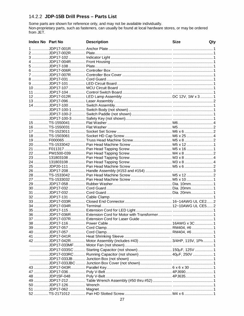
27
14.2.2 JDP-15B Drill Press – Parts List Some parts are shown for reference only, and may not be available individually. Non-proprietary parts, such as fasteners, can usually be found at local hardware stores, or may be ordered from JET.
Index No Part No Description Size Qty 1 ................ JDP17-001R.............. Anchor Plate ............................................................ ...................................... 1 2 ................ JDP17-002R.............. Plate......................................................................... ...................................... 1 3 ................ JDP17-102 ................ Indicator Light .......................................................... ...................................... 1 4 ................ JDP17-004R.............. Front Housing .......................................................... ...................................... 1 5 ................ JDP17-108 ................ Plate......................................................................... ...................................... 1 6 ................ JDP17-006R.............. Controller Box .......................................................... ...................................... 1 7 ................ JDP17-007R.............. Controller Box Cover ............................................... ...................................... 1 8 ................ JDP17-031 ................ Cord Guard .............................................................. ...................................... 1 9 ................ JDP17-101 ................ LED Circuit Board .................................................... ...................................... 1 10 .............. JDP17-107 ................ MCU Circuit Board .................................................. ...................................... 1 11 .............. JDP17-104 ................ Control Switch Board ............................................... ...................................... 1 12 .............. JDP17-012R.............. LED Lamp Assembly ............................................... DC 12V, 1W x 3 ............ 1 13 .............. JDP17-096 ................ Laser Assembly ....................................................... ...................................... 2 14 .............. JDP17-100 ................ Switch Assembly...................................................... ...................................... 1 .................. JDP17-100-1 ............. Switch Body (not shown) ......................................... ...................................... 1 .................. JDP17-100-2 ............. Switch Paddle (not shown) ...................................... ...................................... 1 .................. JDP17-100-3 ............. Safety Key (not shown)............................................ ...................................... 1 15 .............. TS-1550041 .............. Flat Washer ............................................................. M6 ................................. 4 16 .............. TS-1550031 .............. Flat Washer ............................................................. M5 ................................. 2 17 .............. TS-1523011 .............. Socket Set Screw .................................................... M6 x 6 ........................... 2 18 .............. TS-1503061 .............. Socket HD Cap Screw ............................................. M6 x 25 ......................... 4 19 .............. F000065 .................... Truss Head Machine Screw..................................... M5 x 8 ........................... 2 20 .............. TS-1533042 .............. Pan Head Machine Screw ....................................... M5 x 12 ...……………….1 21 .............. F011317 .................... Pan Head Tapping Screw ........................................ M5 x 16 ......................... 1 22 .............. PM1500-039.............. Pan Head Tapping Screw ........................................ M4 x 8 ........................... 2 23 .............. 131803108 ................ Pan Head Tapping Screw ........................................ M3 x 8 ........................... 4 24 .............. 131803108 ................ Pan Head Tapping Screw ........................................ M3 x 8 ........................... 4 25 .............. JDP20-111 ................ Pan Head Machine Screw ....................................... M5 x 6 ........................... 2 26 .............. JDP17-208 ................ Handle Assembly (#153 and #154) ......................... ...................................... 3 28 .............. TS-1533042 .............. Pan Head Machine Screw ....................................... M5 x 12 ......................... 2 27 .............. TS-1533032 .............. Pan Head Machine Screw ....................................... M5 x 10 ......................... 1 29 .............. JDP17-058 ................ Rubber Washer........................................................ Dia. 10mm..................... 1 30 .............. JDP17-032 ................ Cord Guard .............................................................. Dia. 20mm..................... 1 31 .............. JDP17-032 ................ Cord Guard .............................................................. Dia. 20mm..................... 1 32 .............. JDP17-131 ................ Cable Clamp ........................................................... ...................................... 1 33 .............. JDP17-033R.............. Closed End Connector............................................. 16~14AWG UL CE2 ...... 2 34 .............. JDP17-034R.............. Terminal ................................................................... 12~10AWG UL CE5 ...... 2 35 .............. JDP17-115 ................ Extension Cord for LED Light .................................. ...................................... 1 36 .............. JDP17-036R.............. Extension Cord for Motor with Transformer ............. ...................................... 1 37 .............. JDP17-037R.............. Extension Cord for Laser Guide .............................. ...................................... 1 38 .............. JDP17-116 ................ Power Cable ............................................................ 16AWG x 3C ................. 1 39 .............. JDP17-057 ................ Cord Clamp.............................................................. RM404, #6 .................... 1 40 .............. JDP17-057 ................ Cord Clamp.............................................................. RM404, #6 .................... 1 41 .............. JDP17-041R.............. Heat Shrinking Sleeve ........................................... ........................................ 1 42 .............. JDP17-042R.............. Motor Assembly (includes #43) ............................... 3/4HP, 115V, 1Ph ......... 1 .................. JDP17-033MF ........... Motor Fan (not shown)............................................. ...................................... 1 .................. JDP17-033SC ........... Starting Capacitor (not shown) ................................ 150μF, 125V ................. 1 .................. JDP17-033RC ........... Running Capacitor (not shown) ............................... 40μF, 250V ................... 1 .................. JDP17-033JB ............ Junction Box (not shown) ........................................ ...................................... 1 .................. JDP17-033JBC ......... Junction Box Cover (not shown) .............................. ...................................... 1 43 .............. JDP17-043R.............. Parallel Key.............................................................. 6 x 6 x 30 ...................... 1 47 .............. JDP17-036 ................ Poly V-Belt ............................................................... 4PJ690 .......................... 1 48 .............. JDP15F-048 .............. Poly V-Belt ............................................................... 4PJ635 .......................... 1 49 .............. JDP17-212 ................ Table Wrench Assembly (#50 thru #52) .................. ...................................... 1 50 .............. JDP17-126 ................ Wrench .................................................................... ...................................... 1 51 .............. JDP17-062 ................ Magnet ..................................................................... ...................................... 1 52 .............. TS-2171012 .............. Pan HD Slotted Screw ............................................. M4 x 6 ........................... 1
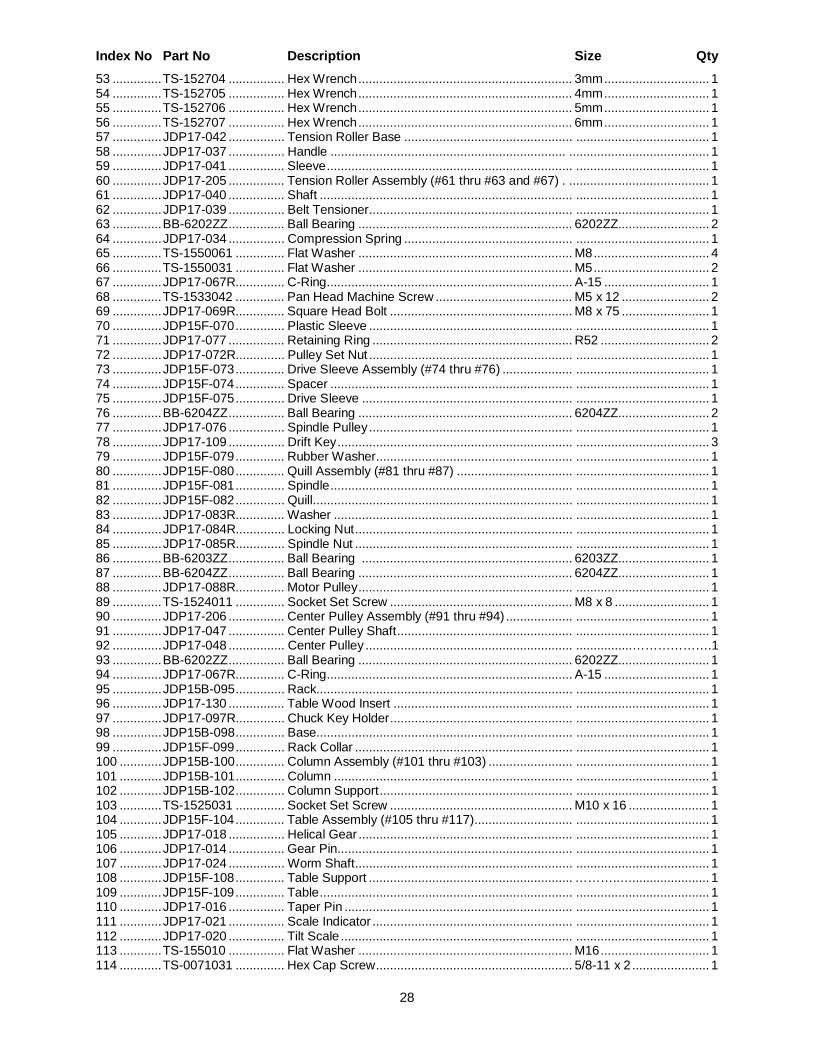
28
Index No Part No Description Size Qty 53 .............. TS-152704 ................ Hex Wrench ............................................................. 3mm .............................. 1 54 .............. TS-152705 ................ Hex Wrench ............................................................. 4mm .............................. 1 55 .............. TS-152706 ................ Hex Wrench ............................................................. 5mm .............................. 1 56 .............. TS-152707 ................ Hex Wrench ............................................................. 6mm .............................. 1 57 .............. JDP17-042 ................ Tension Roller Base ................................................ ...................................... 1 58 .............. JDP17-037 ................ Handle ................................................................... ........................................ 1 59 .............. JDP17-041 ................ Sleeve ...................................................................... ...................................... 1 60 .............. JDP17-205 ................ Tension Roller Assembly (#61 thru #63 and #67) . ........................................ 1 61 .............. JDP17-040 ................ Shaft ........................................................................ ...................................... 1 62 .............. JDP17-039 ................ Belt Tensioner.......................................................... ...................................... 1 63 .............. BB-6202ZZ ................ Ball Bearing ............................................................. 6202ZZ.......................... 2 64 .............. JDP17-034 ................ Compression Spring ................................................ ...................................... 1 65 .............. TS-1550061 .............. Flat Washer ............................................................. M8 ................................. 4 66 .............. TS-1550031 .............. Flat Washer ............................................................. M5 ................................. 2 67 .............. JDP17-067R.............. C-Ring...................................................................... A-15 .............................. 1 68 .............. TS-1533042 .............. Pan Head Machine Screw ....................................... M5 x 12 ......................... 2 69 .............. JDP17-069R.............. Square Head Bolt .................................................... M8 x 75 ......................... 1 70 .............. JDP15F-070 .............. Plastic Sleeve .......................................................... ...................................... 1 71 .............. JDP17-077 ................ Retaining Ring ......................................................... R52 ............................... 2 72 .............. JDP17-072R.............. Pulley Set Nut .......................................................... ...................................... 1 73 .............. JDP15F-073 .............. Drive Sleeve Assembly (#74 thru #76) .................... ...................................... 1 74 .............. JDP15F-074 .............. Spacer ..................................................................... ...................................... 1 75 .............. JDP15F-075 .............. Drive Sleeve ............................................................ ...................................... 1 76 .............. BB-6204ZZ ................ Ball Bearing ............................................................. 6204ZZ.......................... 2 77 .............. JDP17-076 ................ Spindle Pulley .......................................................... ...................................... 1 78 .............. JDP17-109 ................ Drift Key ................................................................... ...................................... 3 79 .............. JDP15F-079 .............. Rubber Washer........................................................ ...................................... 1 80 .............. JDP15F-080 .............. Quill Assembly (#81 thru #87) ................................. ...................................... 1 81 .............. JDP15F-081 .............. Spindle ..................................................................... ...................................... 1 82 .............. JDP15F-082 .............. Quill.......................................................................... ...................................... 1 83 .............. JDP17-083R.............. Washer .................................................................... ...................................... 1 84 .............. JDP17-084R.............. Locking Nut .............................................................. ...................................... 1 85 .............. JDP17-085R.............. Spindle Nut .............................................................. ...................................... 1 86 .............. BB-6203ZZ ................ Ball Bearing ............................................................ 6203ZZ.......................... 1 87 .............. BB-6204ZZ ................ Ball Bearing ............................................................. 6204ZZ.......................... 1 88 .............. JDP17-088R.............. Motor Pulley ............................................................. ...................................... 1 89 .............. TS-1524011 .............. Socket Set Screw .................................................... M8 x 8 ........................... 1 90 .............. JDP17-206 ................ Center Pulley Assembly (#91 thru #94) ................... ...................................... 1 91 .............. JDP17-047 ................ Center Pulley Shaft .................................................. ...................................... 1 92 .............. JDP17-048 ................ Center Pulley ........................................................... ................……………….1 93 .............. BB-6202ZZ ................ Ball Bearing ............................................................. 6202ZZ.......................... 1 94 .............. JDP17-067R.............. C-Ring...................................................................... A-15 .............................. 1 95 .............. JDP15B-095 .............. Rack......................................................................... ...................................... 1 96 .............. JDP17-130 ................ Table Wood Insert ................................................... ...................................... 1 97 .............. JDP17-097R.............. Chuck Key Holder .................................................... ...................................... 1 98 .............. JDP15B-098 .............. Base......................................................................... ...................................... 1 99 .............. JDP15F-099 .............. Rack Collar .............................................................. ...................................... 1 100 ............ JDP15B-100 .............. Column Assembly (#101 thru #103) ........................ ...................................... 1 101 ............ JDP15B-101 .............. Column .................................................................... ...................................... 1 102 ............ JDP15B-102 .............. Column Support ....................................................... ...................................... 1 103 ............ TS-1525031 .............. Socket Set Screw .................................................... M10 x 16 ....................... 1 104 ............ JDP15F-104 .............. Table Assembly (#105 thru #117)............................ ...................................... 1 105 ............ JDP17-018 ................ Helical Gear ............................................................. ...................................... 1 106 ............ JDP17-014 ................ Gear Pin................................................................... ...................................... 1 107 ............ JDP17-024 ................ Worm Shaft .............................................................. ...................................... 1 108 ............ JDP15F-108 .............. Table Support .......................................................... ………..…...................... 1 109 ............ JDP15F-109 .............. Table ........................................................................ ...................................... 1 110 ............ JDP17-016 ................ Taper Pin ................................................................. ...................................... 1 111 ............ JDP17-021 ................ Scale Indicator ......................................................... ...................................... 1 112 ............ JDP17-020 ................ Tilt Scale .................................................................. ...................................... 1 113 ............ TS-155010 ................ Flat Washer ............................................................. M16 ............................... 1 114 ............ TS-0071031 .............. Hex Cap Screw ........................................................ 5/8-11 x 2 ...................... 1
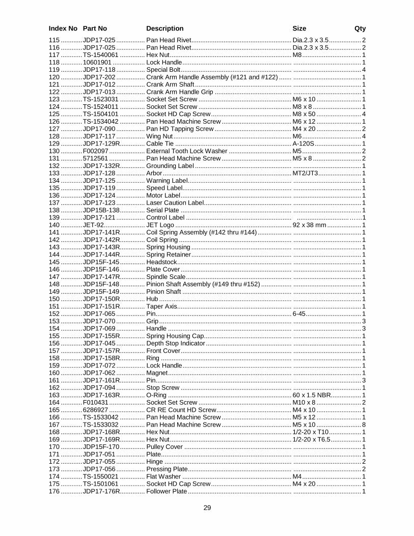
29
Index No Part No Description Size Qty 115 ............ JDP17-025 ................ Pan Head Rivet........................................................ Dia.2.3 x 3.5 .................. 2 116 ............ JDP17-025 ................ Pan Head Rivet........................................................ Dia.2.3 x 3.5 .................. 2 117 ............ TS-1540061 .............. Hex Nut .................................................................... M8 ................................. 1 118 ............ 10601901 .................. Lock Handle ............................................................. ...................................... 1 119 ............ JDP17-118 ................ Special Bolt .............................................................. ...................................... 4 120 ............ JDP17-202 ................ Crank Arm Handle Assembly (#121 and #122) ....... ...................................... 1 121 ............ JDP17-012 ................ Crank Arm Shaft ...................................................... ...................................... 1 122 ............ JDP17-013 ................ Crank Arm Handle Grip ........................................... ...................................... 1 123 ............ TS-1523031 .............. Socket Set Screw .................................................... M6 x 10 ......................... 1 124 ............ TS-1524011 .............. Socket Set Screw .................................................... M8 x 8 ........................... 1 125 ............ TS-1504101 .............. Socket HD Cap Screw ............................................. M8 x 50 ......................... 4 126 ............ TS-1534042 .............. Pan Head Machine Screw ....................................... M6 x 12 ......................... 1 127 ............ JDP17-090 ................ Pan HD Tapping Screw ........................................... M4 x 20 ......................... 2 128 ............ JDP17-117 ................ Wing Nut .................................................................. M6 ................................. 4 129 ............ JDP17-129R.............. Cable Tie ................................................................. A-120S .......................... 1 130 ............ F002097 .................... External Tooth Lock Washer ................................... M5 ................................. 2 131 ............ 5712561 .................... Pan Head Machine Screw ....................................... M5 x 8 ........................... 2 132 ............ JDP17-132R.............. Grounding Label ...................................................... ...................................... 1 133 ............ JDP17-128 ................ Arbor ........................................................................ MT2/JT3 ........................ 1 134 ............ JDP17-125 ................ Warning Label.......................................................... ...................................... 1 135 ............ JDP17-119 ................ Speed Label............................................................. ...................................... 1 136 ............ JDP17-124 ................ Motor Label .............................................................. ...................................... 1 137 ............ JDP17-123 ................ Laser Caution Label................................................. ...................................... 1 138 ............ JDP15B-138 .............. Serial Plate .............................................................. ...................................... 1 139 ............ JDP17-121 ................ Control Label ........................................................... ............................. ……1 140 ............ JET-92....................... JET Logo ................................................................. 92 x 38 mm ................... 1 141 ............ JDP17-141R.............. Coil Spring Assembly (#142 thru #144) ................... ...................................... 1 142 ............ JDP17-142R.............. Coil Spring ............................................................... ...................................... 1 143 ............ JDP17-143R.............. Spring Housing ........................................................ ...................................... 1 144 ............ JDP17-144R.............. Spring Retainer ........................................................ ...................................... 1 145 ............ JDP15F-145 .............. Headstock ................................................................ ...................................... 1 146 ............ JDP15F-146 .............. Plate Cover .............................................................. ...................................... 1 147 ............ JDP17-147R.............. Spindle Scale ........................................................... ...................................... 1 148 ............ JDP15F-148 .............. Pinion Shaft Assembly (#149 thru #152) ................. ...................................... 1 149 ............ JDP15F-149 .............. Pinion Shaft ............................................................. ...................................... 1 150 ............ JDP17-150R.............. Hub .......................................................................... ...................................... 1 151 ............ JDP17-151R.............. Taper Axis................................................................ ...................................... 1 152 ............ JDP17-065 ................ Pin............................................................................ 6-45 ............................... 1 153 ............ JDP17-070 ................ Grip .......................................................................... ...................................... 3 154 ............ JDP17-069 ................ Handle ..................................................................... ...................................... 3 155 ............ JDP17-155R.............. Spring Housing Cap................................................. ...................................... 1 156 ............ JDP17-045 ................ Depth Stop Indicator ................................................ ...................................... 1 157 ............ JDP17-157R.............. Front Cover .............................................................. ...................................... 1 158 ............ JDP17-158R.............. Ring ......................................................................... ...................................... 1 159 ............ JDP17-072 ................ Lock Handle ............................................................. ...................................... 1 160 ............ JDP17-062 ................ Magnet ..................................................................... ...................................... 1 161 ............ JDP17-161R.............. Pin............................................................................ ...................................... 3 162 ............ JDP17-094 ................ Stop Screw .............................................................. ...................................... 1 163 ............ JDP17-163R.............. O-Ring ..................................................................... 60 x 1.5 NBR................. 1 164 ............ F010431 .................... Socket Set Screw .................................................... M10 x 8 ......................... 2 165 ............ 6286927 .................... CR RE Count HD Screw .......................................... M4 x 10 ......................... 1 166 ............ TS-1533042 .............. Pan Head Machine Screw ....................................... M5 x 12 ......................... 1 167 ............ TS-1533032 .............. Pan Head Machine Screw ....................................... M5 x 10 ......................... 8 168 ............ JDP17-168R.............. Hex Nut .................................................................... 1/2-20 x T10 .................. 1 169 ............ JDP17-169R.............. Hex Nut .................................................................... 1/2-20 x T6.5 ................. 1 170 ............ JDP15F-170 .............. Pulley Cover ............................................................ ...................................... 1 171 ............ JDP17-051 ................ Plate......................................................................... ...................................... 1 172 ............ JDP17-055 ................ Hinge ....................................................................... ...................................... 2 173 ............ JDP17-056 ................ Pressing Plate.......................................................... ...................................... 2 174 ............ TS-1550021 .............. Flat Washer ............................................................. M4 ................................. 1 175 ............ TS-1501061 .............. Socket HD Cap Screw ............................................. M4 x 20 ......................... 1 176 ............ JDP17-176R.............. Follower Plate .......................................................... ...................................... 1

30
Index No Part No Description Size Qty 177 ............ TS-1533032 .............. Pan Head Machine Screw ....................................... M5 x 10 ......................... 4 178 ............ JDP20-111 ................ Pan Head Machine Screw ....................................... M5 x 6 ........................... 4 179 ............ JDP17-211 ................ Chuck Assembly (#180 and #181)........................... ...................................... 1 180 ............ JDP17-091 ................ Chuck Key ............................................................... T4 .................................. 1 181 ............ JDP17-092 ................ Chuck....................................................................... RJ-16L .......................... 1 182 ............ TS-1533032 .............. Pan Head Machine Screw ....................................... M5 x 10 ......................... 2 183 ............ JDP17-090 ................ Pan HD Tapping Screw ........................................... M4 x 16 ......................... 1 184 ............ JDP20-111 ................ Pan Head Machine Screw ....................................... M5 x 6 ........................... 2 185 ............ TS-1533032 .............. Pan Head Machine Screw ....................................... M5 x 10 ......................... 1 .................. JDP17-HP2 ............... Hardware Package (see sect. 6.2 for included items) .................................... 1
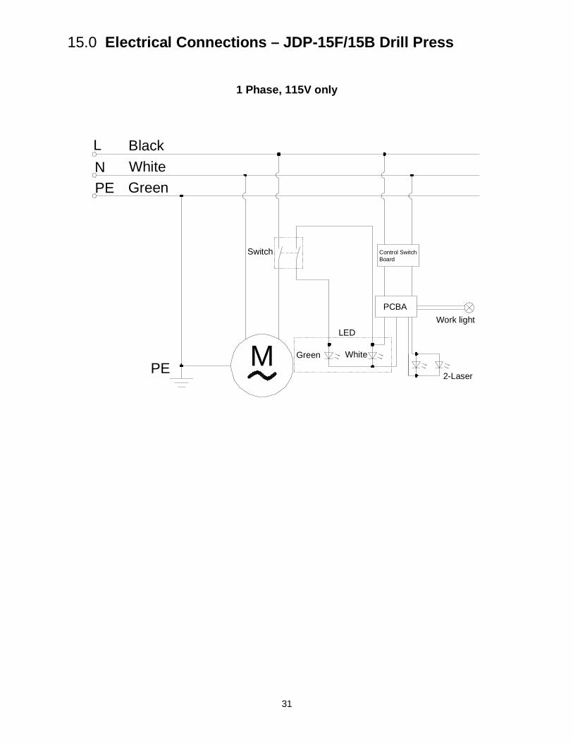
31
15.0 Electrical Connections – JDP-15F/15B Drill Press
1 Phase, 115V only
LN
PE M
PE
PCBA
Control SwitchBoard
Work light
Switch
BlackWhiteGreen
WhiteGreen
2-Laser
LED

32
427 New Sanford Road LaVergne, Tennessee 37086
Phone: 800-274-6848 www.jettools.com