operating instructions and parts manual variable …go.rockler.com/tech/rtd10000187ab.pdf ·...
TRANSCRIPT

Operating Instructions and Parts Manual Variable Speed Mini Lathe Model JML-1014VSI and JWL-1220VS
WMH TOOL GROUP 2420 Vantage Drive Elgin, Illinois 60124 Part No. M-708375VSPh.: 800-274-6848 Revision A2 1/08www.wmhtoolgroup.com Copyright © WMH Tool Group
(23361)
RTD10000187AB
Note: Rockler may not carry all products and/or sizes listed in this vendor's publication

2
Warranty and Service WMH Tool Group, Inc., warrants every product it sells. If one of our tools needs service or repair, one of our Authorized Service Centers located throughout the United States can give you quick service. In most cases, any of these WMH Tool Group Authorized Service Centers can authorize warranty repair, assist you in obtaining parts, or perform routine maintenance and major repair on your JET® tools. For the name of an Authorized Service Center in your area call 1-800-274-6848. MORE INFORMATION WMH Tool Group is consistently adding new products to the line. For complete, up-to-date product information, check with your local WMH Tool Group distributor, or visit jettools.com. WARRANTY JET products carry a limited warranty which varies in duration based upon the product (MW = Metalworking, WW = Woodworking).
WHAT IS COVERED? This warranty covers any defects in workmanship or materials subject to the exceptions stated below. Cutting tools, abrasives and other consumables are excluded from warranty coverage. WHO IS COVERED? This warranty covers only the initial purchaser of the product. WHAT IS THE PERIOD OF COVERAGE? The general JET warranty lasts for the time period specified in the product literature of each product. WHAT IS NOT COVERED? Five Year Warranties do not cover woodworking (WW) products used for commercial, industrial or educational purposes. Woodworking products with Five Year Warranties that are used for commercial, industrial or education purposes revert to a One Year Warranty. This warranty does not cover defects due directly or indirectly to misuse, abuse, negligence or accidents, normal wear-and-tear, improper repair or alterations, or lack of maintenance. HOW TO GET SERVICE The product or part must be returned for examination, postage prepaid, to a location designated by us. For the name of the location nearest you, please call 1-800-274-6848. You must provide proof of initial purchase date and an explanation of the complaint must accompany the merchandise. If our inspection discloses a defect, we will repair or replace the product, or refund the purchase price, at our option. We will return the repaired product or replacement at our expense unless it is determined by us that there is no defect, or that the defect resulted from causes not within the scope of our warranty in which case we will, at your direction, dispose of or return the product. In the event you choose to have the product returned, you will be responsible for the shipping and handling costs of the return. HOW STATE LAW APPLIES This warranty gives you specific legal rights; you may also have other rights which vary from state to state. LIMITATIONS ON THIS WARRANTY WMH TOOL GROUP LIMITS ALL IMPLIED WARRANTIES TO THE PERIOD OF THE LIMITED WARRANTY FOR EACH PRODUCT. EXCEPT AS STATED HEREIN, ANY IMPLIED WARRANTIES OR MERCHANTABILITY AND FITNESS ARE EXCLUDED. SOME STATES DO NOT ALLOW LIMITATIONS ON HOW LONG THE IMPLIED WARRANTY LASTS, SO THE ABOVE LIMITATION MAY NOT APPLY TO YOU. WMH TOOL GROUP SHALL IN NO EVENT BE LIABLE FOR DEATH, INJURIES TO PERSONS OR PROPERTY, OR FOR INCIDENTAL, CONTINGENT, SPECIAL, OR CONSEQUENTIAL DAMAGES ARISING FROM THE USE OF OUR PRODUCTS. SOME STATES DO NOT ALLOW THE EXCLUSION OR LIMITATION OF INCIDENTAL OR CONSEQUENTIAL DAMAGES, SO THE ABOVE LIMITATION OR EXCLUSION MAY NOT APPLY TO YOU. WMH Tool Group sells through distributors only. The specifications in WMH catalogs are given as general information and are not binding. Members of WMH Tool Group reserve the right to effect at any time, without prior notice, those alterations to parts, fittings, and accessory equipment which they may deem necessary for any reason whatsoever. JET® branded products are not sold in Canada by WMH Tool Group.

3
Table of Contents Warranty and Service............................................................................................................................................2Table of Contents..................................................................................................................................................3Warning.................................................................................................................................................................3Introduction ...........................................................................................................................................................5Specifications ........................................................................................................................................................5Optional Accessories ............................................................................................................................................5Electrical Requirements ........................................................................................................................................6Receiving...............................................................................................................................................................7Assembly...............................................................................................................................................................8Operation...............................................................................................................................................................9
Work Lamp (JWL-1220 only).............................................................................................................................9Adjusting the Tool Rest ...................................................................................................................................11Variable Speed Control ...................................................................................................................................12Changing Spindle Speeds...............................................................................................................................13Belt Replacement ............................................................................................................................................14Removing and Installing Live Center...............................................................................................................14Indexer Operation............................................................................................................................................15
Parts Breakdown for JML-1014VSI.....................................................................................................................16Parts List for JML-1014VSI ................................................................................................................................17Electrical Connections JML-1014VSI..................................................................................................................19Parts Breakdown for JWL-1220VS ....................................................................................................................20Parts List for JWL-1220VS .................................................................................................................................21Electrical Connection JWL-1220VS ...................................................................................................................23
Warning
For your own safety, read this instruction manual before operating the lathe.Do not wear gloves, necktie, or loose clothing.
Tighten all locks before operating. Rotate the workpiece by hand before applying power.
Rough out the wor piece before installing on the faceplate. Do not mount a split workpiece or one containing a knot.
Use the lowest speed when starting a new workpiece.
Keep guards in place and in working order.
Remove adjusting keys and wrenches. Form the habit of checking to see that keys and adjusting wrenches are removed from the tool before turning it on.
Keep the work area clean. Cluttered areas and benches invite accidents.
Do not use in a dangerous environment. Don’t use power tools in damp or wet locations, or expose them to rain. Keep work area well lighted.
Keep children away. All visitors should be a kept safe distance from the work area.
Make the workshop kid proof with padlocks, master switches, or by removing starter keys.
Don’t force the tool. It will do the job better and safer at the rate for which it was designed.
Use the right tool. Don’t force a tool or attachment to do a job for which it was not designed.
Use the proper extension cord. Make sure your extension cord is in good condition. When using an extension cord, be sure to use one heavy enough to carry the current your product will draw. An undersize cord will cause a drop in the line voltage resulting in loss of power and overheating. For runs up to 25 feet, use an 18 AWG or larger gauge cord. For runs up to 50 feet, use a 16 AWG or larger gauge cord. For
4
runs up to 100 feet, use a 14 AWG or larger gauge cord. For runs up to 150 feet, use a 12 AWG or larger gauge cord. Runs over 150 feet are not recommended. If in doubt, use the next heavier gauge. The smaller the gauge number, the heavier the cord.
Wear proper apparel. Do not wear loose clothing, gloves, neckties, rings, bracelets, or other jewelry which may get caught in moving parts. Nonslip footwear is recommended. Wear protective hair covering to contain long hair.
Wear eye protection. Always use safety glasses. Also use face or dust masks if the cutting operation is dusty. Everyday eyeglasses only have impact resistant lenses, they are NOT safety glasses.
Secure work. Use clamps or a vise to hold the work when it’s practical. It’s safer than using your hand and it frees both hands to operate the tool.
Don’t overreach. Keep proper footing and balance at all times.
Maintain tools with care. Keep tools sharp and clean for best and safest performance. Follow instructions for lubricating and changing accessories.
Reduce the risk of unintentional starting. Make sure the switch is in the off position before plugging in the machine.
Disconnect tools before servicing; when changing accessories, such as blades, bits cutters, and the like.
Use recommended accessories. Consult the owner’s manual for recommended accessories. The use of improper accessories may cause a risk of injury.
Never stand on a tool. Serious injury could occur if the tool is tipped or if the cutting tool is unintentionally contacted.
Check damaged parts. Before further use of the tool, a guard or other part that is damaged should be carefully checked to determine that it will operate properly and perform its intended function. Check for alignment of moving parts, binding of moving parts, breakage of parts, mounting, and any other conditions that may affect its operation. A guard or other part that is damaged should be properly repaired or replaced.
Direction of feed. Feed work into a blade or cutter against the direction of rotation of the blade or cutter only.
Never leave the tool running unattended. Turn the power off. Don’t leave the tool until it comes to a complete stop.
Drugs, alcohol, medication. Do not operate this machine while under the influence of drugs, alcohol, or any medication.
Health hazards. Some dust created by power sanding, sawing, grinding, drilling and other construction activities contains chemicals known to cause cancer, birth defects or other reproductive harm. Some examples of these chemicals are:
Lead from lead-based paint.
Crystalline silica from bricks and cement and other masonry products.
Arsenic and chromium from chemically-treated lumber.
Your risk from these exposures varies, depending on how often you do this type of work. To reduce your exposure to these chemicals, work in a well-ventilated area, and work with approved safety equipment, such as those dust masks that are specifically designed to filter out microscopic particles.
5
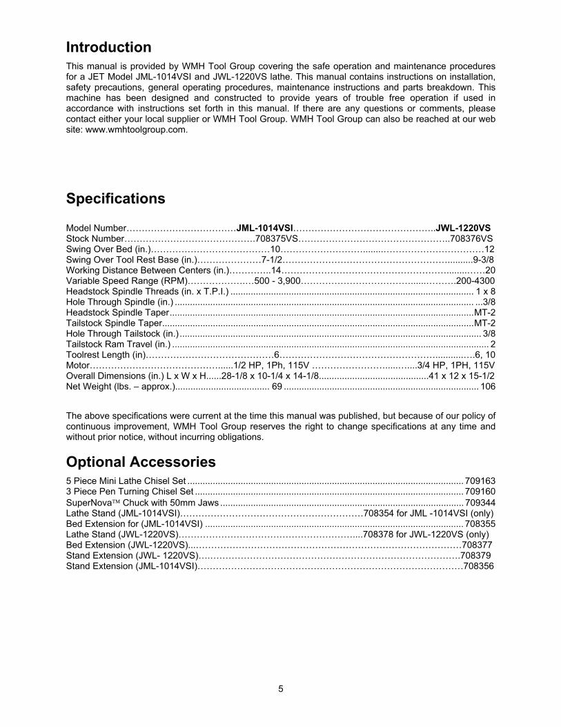
IntroductionThis manual is provided by WMH Tool Group covering the safe operation and maintenance procedures for a JET Model JML-1014VSI and JWL-1220VS lathe. This manual contains instructions on installation, safety precautions, general operating procedures, maintenance instructions and parts breakdown. This machine has been designed and constructed to provide years of trouble free operation if used in accordance with instructions set forth in this manual. If there are any questions or comments, please contact either your local supplier or WMH Tool Group. WMH Tool Group can also be reached at our web site: www.wmhtoolgroup.com.
Specifications
Model Number………………………………JML-1014VSI………………………………………..JWL-1220VSStock Number…………………………………….708375VS…………………………………………..708376VS Swing Over Bed (in.)…………………………………10………………………........……………………………12Swing Over Tool Rest Base (in.)…………………7-1/2………………………………………………..........9-3/8Working Distance Between Centers (in.)…………..14………………………………………………........……20Variable Speed Range (RPM)……………….…500 - 3,900………………………………......……….200-4300 Headstock Spindle Threads (in. x T.P.I.) ................................................................................................ 1 x 8 Hole Through Spindle (in.) ...................................................................................................................... ...3/8 Headstock Spindle Taper........................................................................................................................MT-2 Tailstock Spindle Taper...........................................................................................................................MT-2 Hole Through Tailstock (in.) ....................................................................................................................... 3/8 Tailstock Ram Travel (in.) ............................................................................................................................. 2 Toolrest Length (in)……………………………………6……………………………………………...........….6, 10 Motor……………………………………......1/2 HP, 1Ph, 115V …………………….....…....3/4 HP, 1PH, 115V Overall Dimensions (in.) L x W x H......28-1/8 x 10-1/4 x 14-1/8...........................................41 x 12 x 15-1/2 Net Weight (lbs. – approx.)..................................... 69 ............................................................................. 106
The above specifications were current at the time this manual was published, but because of our policy of continuous improvement, WMH Tool Group reserves the right to change specifications at any time and without prior notice, without incurring obligations.
Optional Accessories 5 Piece Mini Lathe Chisel Set ............................................................................................................. 709163 3 Piece Pen Turning Chisel Set .......................................................................................................... 709160 SuperNova Chuck with 50mm Jaws ................................................................................................ 709344 Lathe Stand (JML-1014VSI)……………………………………………………708354 for JML -1014VSI (only) Bed Extension for (JML-1014VSI) ...................................................................................................... 708355 Lathe Stand (JWL-1220VS)…………………………………………………....708378 for JWL-1220VS (only) Bed Extension (JWL-1220VS)...……………………………………………………………………………708377 Stand Extension (JWL- 1220VS)….……………………………………………………………………….708379 Stand Extension (JML-1014VSI)……………………………………………………………………………708356

6
Electrical Requirements
In the event of a malfunction or breakdown, grounding provides a path of least resistance for electric current to reduce the risk of electric shock. This tool is equipped with an electric cord having an equipment-grounding conductor and a grounding plug. The plug must be plugged into a matching outlet that is properly installed and grounded in accordance with all local codes and ordinances.
Do not modify the plug provided. If it will not fit the outlet, have the proper outlet installed by a qualified electrician.
Improper connection of the equipment-grounding conductor can result in a risk of electric shock. The conductor, with insulation having an outer surface that is green with or without yellow stripes, is the equipment-grounding conductor. If repair or replacement of the electric cord or plug is necessary, do not connect the equipment-grounding conductor to a live terminal.
Check with a qualified electrician or service personnel if the grounding instructions are not completely understood, or if in doubt as to whether the tool is properly grounded.
Use only three wire extension cords that have three-prong grounding plugs and three-pole receptacles that accept the tool’s plug.*
Repair or replace a damaged or worn cord immediately.
This tool is intended for use on a circuit that has an outlet that looks the one in illustration A, Figure 1. The tool has a grounding plug like that in illustration A. A temporary adapter, like the adapter in illustration B, may be used to connect this plug to a two-pole receptacle, as shown in illustration B if a properly grounded outlet is not available.** The temporary adapter should only be used until a properly grounded outlet can be installed by a qualified electrician. The green colored rigid ear or tab, extending from the adapter, must be connected to a permanent ground such as a properly grounded outlet box.
* Canadian electrical codes require extension cords to be certified SJT type or better. ** Use of an adapter in Canada is not acceptable.
Figure 1

7
Receiving1. Remove contents from the shipping box.
2. Inspect contents for shipping damage and report damage, if any, to your distributor.
3. Be sure to keep the box and packing material should you need to pack the lathe for moving.
4. Exposed metal surfaces on the lathe have been factory-treated with a protectant, and should be cleaned with a soft rag. Do not clean the lathe with anything other than a damp cloth or a mild solvent. Use of heavy solvents, paint thinner, gasoline, etc. will damage painted surfaces.
Contents of the Shipping Carton: JML-1014VSI (708375VS) JWL-1220VS (708376VS)
1 – Lathe with motor and tailstock 1 – Lathe with motor and tailstock
1-Control Box (with 2 screws) 1-Control Box (with 2 screws)
1 – 6” Tool rest 2 – Tool rests (6”,10”) 1 – Face plate 1 – Face plate 1 – Knockout rod 1 – Knockout rod 1 – Live center 1 – Live center 1 – Spur center 1 – Spur center 1 – Safety goggles 1 – Safety goggles 1 – Owner’s manual 1 – Tool caddy 1 – Warranty card 1 – Work lamp (bulb 1 – 3mm hex wrench not included)1 – 5mm hex wrench 1 – Owner’s manual 1 – Warranty card 1 – 3mm hex wrench 1 – 5mm hex wrench

8
AssemblyMount the control box (shown in Figure 1) to the headstock side of the lathe, by inserting the two screws through the hinge plate and into the threaded holes in the lathe body. If desired, the lathe can be bolted to a work table or stand by removing the rubber feet and inserting screws through the holes in the base. NOTE: The table or stand should have an opening directly beneath the motor to prevent build-up of shavings around the motor’s fan housing. Stands specifically made for these lathes are available (JML-1014VSI, Stand Stock #708354) and (JWL-1220VS, Stand Stock #708378).
(Figure1)
The JWL-1220VS requires minor assembly: Install the tool caddy using the two pan head screws, as shown in Figure 1a. The JWL-1220VS is provided with a lifting handle on each end. These can be pushed in when not in use.
(Figure 1a)

9
OperationTailstock Handwheel (A, Figure 2) - Turn clockwise to move tailstock spindle forward. Turn counter-clockwise to retract tailstock spindle.
Tailstock Spindle Lock (B, Figure 2) - Locks tailstock spindle. Release to adjust with handwheel.
Tailstock Lock (C, Figure 2) - Locks tailstock in position on the bed. Release to move tailstock assembly closer to or farther from the headstock.
The tailstock spindle is hollow. This can be useful for inserting a long bit to drill a hole in the center of a workpiece on the faceplate.
The clamping device on the tailstock has been factory adjusted; however if further adjustment should be needed, slide the tailstock off the end of the bed, and tighten or loosen the nut (D, Figure 3) beneath the tailstock.
Work Lamp (JWL-1220 only) The 20” lathe is provided with a flexible work lamp which uses a 40-watt bulb (not provided). Position the work lamp so that wood chips do not accumulate inside the lamp shade and pose a fire hazard.
Use only a 40-watt or smaller bulb in the work lamp.
Figure 2
Figure 3
10
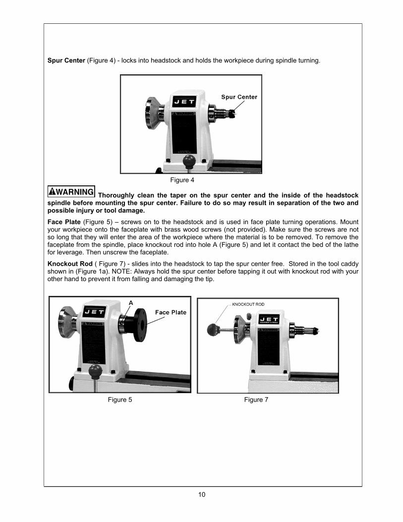
Spur Center (Figure 4) - locks into headstock and holds the workpiece during spindle turning.
Figure 4
Thoroughly clean the taper on the spur center and the inside of the headstock spindle before mounting the spur center. Failure to do so may result in separation of the two and possible injury or tool damage.
Face Plate (Figure 5) – screws on to the headstock and is used in face plate turning operations. Mount your workpiece onto the faceplate with brass wood screws (not provided). Make sure the screws are not so long that they will enter the area of the workpiece where the material is to be removed. To remove the faceplate from the spindle, place knockout rod into hole A (Figure 5) and let it contact the bed of the lathe for leverage. Then unscrew the faceplate.
Knockout Rod ( Figure 7) - slides into the headstock to tap the spur center free. Stored in the tool caddy shown in (Figure 1a). NOTE: Always hold the spur center before tapping it out with knockout rod with your other hand to prevent it from falling and damaging the tip.
Figure 5 Figure 7

11
Tool Rest (Figure 8) - attaches to the bed. Used to steady cutting tool during spindle turning or face plate operations.
Figure 8
Adjusting the Tool Rest Position the tool rest as close to the work piece as possible. It should be 1/8" above the centerline of the work piece.
Position the tool rest base on the bed by releasing the lock handle (A, Figure 8) and sliding onto the desired position. Tighten handle (A, Figure 8) to lock. Adjust the height of the tool rest by loosening handle (B, Figure 8) and raising or lowering tool rest (Figure 8).
Should adjustment of the tool rest clamping device become necessary, turn off the machine, reach under the bed, and adjust the clamping nut (Figure 3).
NOTE: The lock levers (B, Figure 8) are spring loaded. Simply pull up on the lever, rotate it on the pin, then release.

12
Variable Speed Control The variable speed control box contains the electrical connections to the motor, and has three external controls.
Always set the speed control knob to its lowest setting before starting lathe. Never start a workpiece at maximum speed.
Figure 9
Power Switch (A, Figure 9) – controls electrical power to lathe motor. Flip toggle switch on ON position to start the motor. The lathe will begin turning and driving the headstock spindle. The lathe will reach full speed in about 1 to 3 seconds. The time it will take the motor to reach the speed set by the speed control knob depends on the size and weight of the workpiece. Move the switch to the OFF position to stop the lathe. Wait for the workpiece to come to a complete stop.
Speed Control Knob (B, Figure 9) – sets the speed of the lathe to suit the weight of the workpiece or type of tool being used. After lathe is started, turn knob clockwise to increase spindle speed. Counterclockwise decreases speed.
Reset Button (C, Figure 9) – contains overload protection. If the lathe stops suddenly during operation, or does not start when the power switch is set to ON, an overload condition may have occurred. Flip the power switch to OFF, and push the reset button. Then re-start the lathe.

13
Figure 10 Figure 11
Figure 12
Changing Spindle Speeds The variable speeds of the lathe are controlled by the speed knob on the control box as well as the position of the belt on the pulleys.
1. Disconnect machine from the power source (unplug).
2. Pull open the control box at the left side of the base (A, Figure 10), and the access door at the back side of the headstock (A, Figure 11) to expose the pulleys.
3. Loosen the motor plate lock handle (A, Figure 12). Lift up on the motor plate handle (B, Figure 12) to take tension off the belt.
4. Move the belt (B, Figure 10) to the desired pulley groove according to the speed chart found on the inside of the headstock access door. Be sure the belt is aligned with spindle pulley and motor pulley.
5. Tension the belt by pushing down on the motor plate handle (B, Figure 12) and lock in place.

14
Belt Replacement 1. Disconnect the machine from the power source (unplug).
2. Open the access doors at the left side of the base (Figure 10), and at the back side of the headstock (Figure 11).
3. Loosen the motor plate lock handle (A, Figure 12). Lift up on the motor plate handle (B, Figure 12) to take tension off the belt.
4. Loosen the set screw (B, Figure 11) on spindle pulley (upper).
5. Loosen two set screws in handwheel (C, Figure 11). Unscrew the handwheel while holding onto the spindle.
6. Remove handwheel and pull the spindle out while holding onto the spindle pulley.
7. Place the new belt on the spindle pulley. Place the spindle pulley back into the headstock the same way it was removed.
8. Insert the spindle into the spindle pulley aligning the key.
9. Thread the handwheel onto the spindle leaving a little space between the handwheel and headstock. Tighten set screws.
10. Center the spindle pulley and tighten set screw.
11. Wrap the belt around the motor pulley (lower). Be sure the belt is aligned with spindle pulley and motor pulley.
12. Tension the belt and tighten the motor plate lock handle.
Removing and Installing Live Center 1. Loosen tailstock lock handle (B, Figure 13).
2. Turn the tailstock handwheel (A, Figure 13) counter-clockwise until the live center (C, Figure 13) ejects from the spindle. NOTE: Hold the live center in your other hand to prevent it from falling.
3. Before installing the live center into the spindle, the spindle must be extended out from the tailstock body far enough to allow the live center to “seat” in the spindle.
Figure 13

15
Figure 14
Indexer OperationThe index feature allows you to cut evenly spaced features in a workpiece while keeping the Lathe headstock spindle locked; for example, when cutting flutes on a spindle blank with a router, while the spindle blank is secured within the Lathe centers. There are 24 index positions on the lathe.
1. To use the index pin (Figure 14), screw it farther into the headstock until it engages a hole in the spindle pulley.
2. Make your first flute cutting.
3. Unscrew the index pin just enough so that it frees the spindle. Carefully rotate the spindle to the next index position. (If you push inward on the index pin while rotating the spindle, you can feel when it tries to enter the next index position.)
4. Screw in the index pin completely and perform the second flute cutting.
NOTE: Back out the index pin completely to free the spindle before turning on the lathe.

16
Parts Breakdown for JML-1014VSI Lathe
17
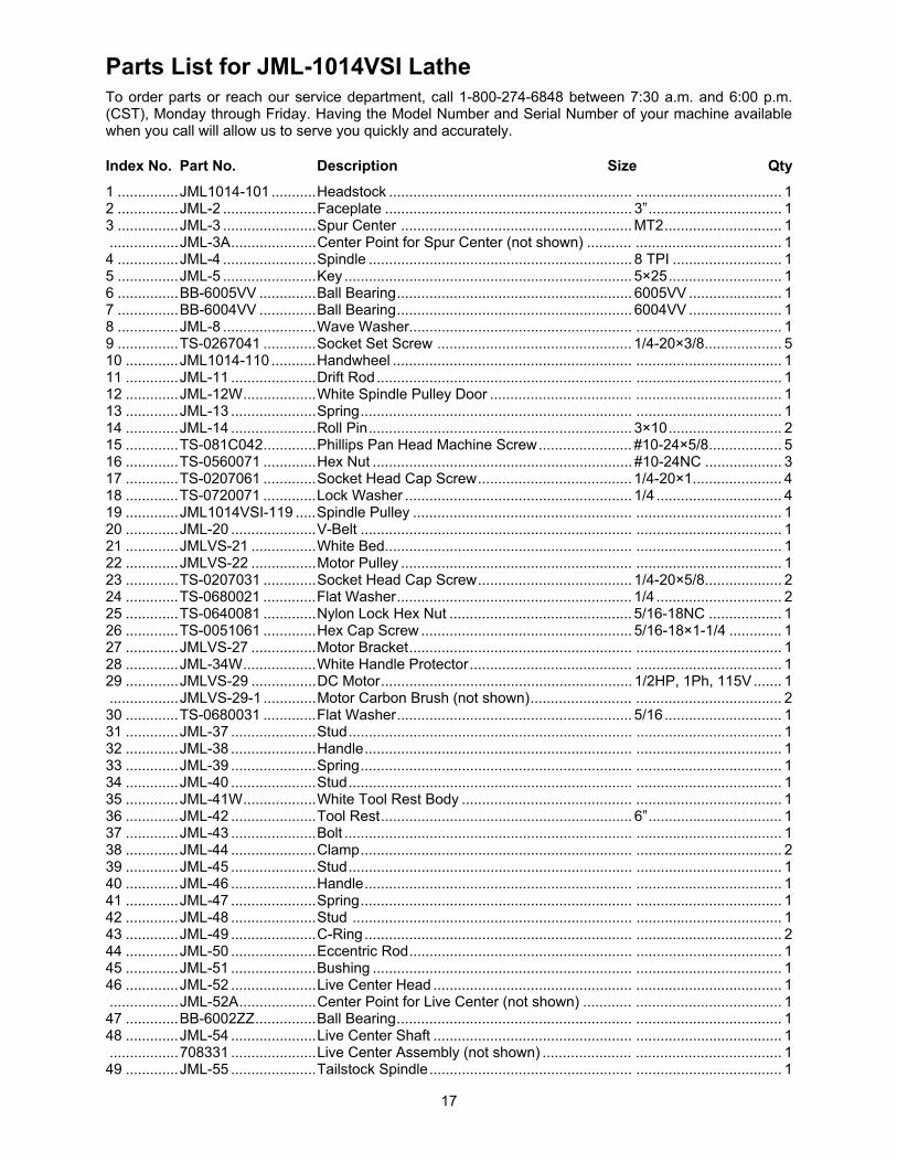
Parts List for JML-1014VSI Lathe To order parts or reach our service department, call 1-800-274-6848 between 7:30 a.m. and 6:00 p.m. (CST), Monday through Friday. Having the Model Number and Serial Number of your machine available when you call will allow us to serve you quickly and accurately.
Index No. Part No. Description Size Qty
1 ...............JML1014-101 ...........Headstock ............................................................ .................................... 1 2 ...............JML-2 .......................Faceplate ............................................................. 3”................................. 1 3 ...............JML-3 .......................Spur Center ......................................................... MT2............................. 1 .................JML-3A.....................Center Point for Spur Center (not shown) ........... .................................... 1 4 ...............JML-4 .......................Spindle ................................................................. 8 TPI ........................... 1 5 ...............JML-5 .......................Key ....................................................................... 5×25............................ 1 6 ...............BB-6005VV ..............Ball Bearing.......................................................... 6005VV ....................... 1 7 ...............BB-6004VV ..............Ball Bearing.......................................................... 6004VV ....................... 1 8 ...............JML-8 .......................Wave Washer....................................................... .................................... 1 9 ...............TS-0267041 .............Socket Set Screw ................................................ 1/4-20×3/8................... 5 10 .............JML1014-110 ...........Handwheel ........................................................... .................................... 1 11 .............JML-11 .....................Drift Rod............................................................... .................................... 1 12 .............JML-12W..................White Spindle Pulley Door ................................... .................................... 1 13 .............JML-13 .....................Spring................................................................... .................................... 1 14 .............JML-14 .....................Roll Pin................................................................. 3×10............................ 2 15 .............TS-081C042.............Phillips Pan Head Machine Screw....................... #10-24×5/8.................. 5 16 .............TS-0560071 .............Hex Nut ................................................................ #10-24NC ................... 3 17 .............TS-0207061 .............Socket Head Cap Screw...................................... 1/4-20×1...................... 418 .............TS-0720071 .............Lock Washer ........................................................ 1/4 ............................... 4 19 .............JML1014VSI-119 .....Spindle Pulley ...................................................... .................................... 1 20 .............JML-20 .....................V-Belt ................................................................... .................................... 1 21 .............JMLVS-21 ................White Bed............................................................. .................................... 1 22 .............JMLVS-22 ................Motor Pulley ......................................................... .................................... 1 23 .............TS-0207031 .............Socket Head Cap Screw...................................... 1/4-20×5/8................... 224 .............TS-0680021 .............Flat Washer.......................................................... 1/4 ............................... 2 25 .............TS-0640081 .............Nylon Lock Hex Nut ............................................. 5/16-18NC .................. 1 26 .............TS-0051061 .............Hex Cap Screw .................................................... 5/16-18×1-1/4 ............. 1 27 .............JMLVS-27 ................Motor Bracket....................................................... .................................... 1 28 .............JML-34W..................White Handle Protector........................................ .................................... 1 29 .............JMLVS-29 ................DC Motor.............................................................. 1/2HP, 1Ph, 115V....... 1 .................JMLVS-29-1 .............Motor Carbon Brush (not shown)......................... .................................... 2 30 .............TS-0680031 .............Flat Washer.......................................................... 5/16............................. 1 31 .............JML-37 .....................Stud...................................................................... .................................... 1 32 .............JML-38 .....................Handle.................................................................. .................................... 1 33 .............JML-39 .....................Spring................................................................... .................................... 1 34 .............JML-40 .....................Stud...................................................................... .................................... 1 35 .............JML-41W..................White Tool Rest Body .......................................... .................................... 1 36 .............JML-42 .....................Tool Rest.............................................................. 6”................................. 1 37 .............JML-43 .....................Bolt ....................................................................... .................................... 1 38 .............JML-44 .....................Clamp................................................................... .................................... 2 39 .............JML-45 .....................Stud...................................................................... .................................... 1 40 .............JML-46 .....................Handle.................................................................. .................................... 1 41 .............JML-47 .....................Spring................................................................... .................................... 1 42 .............JML-48 .....................Stud ..................................................................... .................................... 1 43 .............JML-49 .....................C-Ring .................................................................. .................................... 2 44 .............JML-50 .....................Eccentric Rod....................................................... .................................... 1 45 .............JML-51 .....................Bushing ................................................................ .................................... 1 46 .............JML-52 .....................Live Center Head ................................................. .................................... 1 .................JML-52A...................Center Point for Live Center (not shown) ............ .................................... 1 47 .............BB-6002ZZ...............Ball Bearing.......................................................... .................................... 1 48 .............JML-54 .....................Live Center Shaft ................................................. .................................... 1 .................708331 .....................Live Center Assembly (not shown) ...................... .................................... 1 49 .............JML-55 .....................Tailstock Spindle.................................................. .................................... 1

18
50 .............JML-56 .....................Lead screw........................................................... .................................... 1 51 .............JML-57 .....................E-Ring .................................................................. .................................... 1 52 .............JML-58 .....................Eccentric Rod....................................................... .................................... 1 53 .............JML-59 .....................Stud...................................................................... .................................... 1 54 .............JML-60W..................White Tailstock..................................................... .................................... 1 55 .............JML-61 .....................Handwheel ........................................................... .................................... 1 56 .............JML-62 .....................Handle.................................................................. .................................... 1 57 .............JML-63 .....................C-Ring .................................................................. .................................... 1 58 .............JML-64 .....................Bolt ....................................................................... .................................... 1 59 .............JML-70 .....................Strain Relief Bushing ........................................... .................................... 2 60 .............JML-72 .....................Cord Clamp.......................................................... .................................... 2 61 .............JML-75 .....................Power Cord .......................................................... .................................... 1 62 .............JML-76 .....................Handle.................................................................. .................................... 1 63 .............JML-77 .....................Spring................................................................... .................................... 1 64 .............JML-78 .....................Stud...................................................................... .................................... 1 65 .............JML-79 .....................Safety Goggles .................................................... .................................... 1 66 .............JML-80 .....................Rubber Feet ......................................................... .................................... 4 67 .............JML-81 .....................Clamp Nut ............................................................ M10×1.5P ................... 2 68 .............JML-82 .....................Warning Label ..................................................... .................................... 1 69 .............JMLVS-83 ................Controller Assembly (Items 70-73, 80, 82-91) ..... .................................... 1 70 .............JMLVS-84 ................ON/OFF Switch.................................................... .................................... 1 71 .............JMLVS-85 ................Circuit Breaker ..................................................... .................................... 1 72 .............JMLVS-86 ................Control Pot Assembly .......................................... .................................... 1 73 .............JMLVS-87 ................Knob..................................................................... .................................... 1 74 .............TS-081B012.............Phillips Pan Head Machine Screw....................... #8-32×1/4.................... 4 75 .............JMLVS-89 ................I.D Label............................................................... .................................... 1 76 .............JMLVS-90 ................Speed Label ......................................................... .................................... 1 77 .............JMLVS-91 ................JET Label ............................................................. .................................... 1 78 .............JMLVS-92 ................JET Plaque........................................................... .................................... 1 79 .............JMLVS-93 ................Motor Label .......................................................... .................................... 1 80 .............JMLVS-95 ................Control Panel Label ............................................. .................................... 1 81 .............JMLVS-96 ................Hinge Plate........................................................... .................................... 1 82 .............JMLVS-97 ................Heat Sink.............................................................. .................................... 1 83 .............JMLVS-98 ................Spacer.................................................................. .................................... 4 84 .............JMLVS-99 ................Insulator ............................................................... .................................... 1 85 .............JMLVS-100 ..............Circuit Board ........................................................ .................................... 1 86 .............JMLVS-101 ..............Tap Screw............................................................ .................................... 4 87 .............JMLVS-102 ..............Hex Nut ................................................................ M4×0.7P ..................... 1 88 .............JMLVS-103 ..............Screw ................................................................... M4×0.7P×12 ............... 1 89 .............JMLVS-104 ..............Clamp Bar ............................................................ .................................... 1 90 .............JMLVS-105 ..............Screw ................................................................... M4×0.7P×20 ............... 1 91 .............JMLVS-106 ..............Plastic Cover........................................................ .................................... 1 92 .............JWL1442-170...........Star Washer ......................................................... 3/16............................. 2 93 .............JMLVS-108 ..............Hex Cap Screw .................................................... #10-24 ×3/8................. 2 94 .............TS-0720041 .............Lock Washer ........................................................ #8 ................................ 4 95 .............JMLVS-109 ..............Speed Chart Label ............................................... .................................... 1 96 .............JML1014-187 ...........C-Ring .................................................................. STW-9......................... 1 97 .............JML1014-188 ...........Spring................................................................... .................................... 1 98 .............JML1014-189 ...........Index Pin .............................................................. .................................... 1 99 .............TS-0267021 .............Socket Set Screw................................................. 1/4-20x1/4................... 2
19
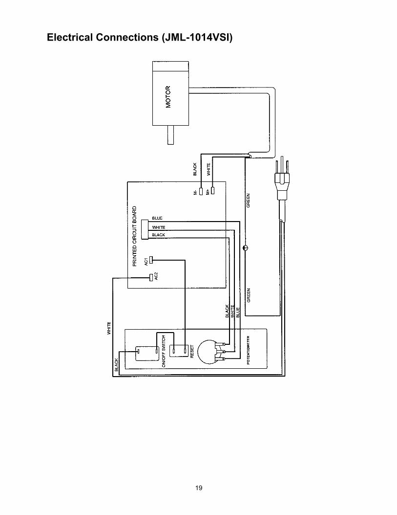
Electrical Connections (JML-1014VSI)

20
Parts Breakdown for (JWL-1220VS Lathe)
73
80
36
80
908
1
12
14
7
10
13
4241
43
44
81
5560
5756
961
62
64
44
81
86
45
37
8788
89
78
68
83
72
54
5352
52A
17
1871
7273
15
20
79
4950
4951
1184
68
59
6358
34
33
35
28
29
3031
32
66
85
16
8619
65
4
2
3
3A
21
76
77
38
39
40
4647
48
47
75
74
67
82
71
101
102

21
Parts List for JWL-1220VS Lathe
Index No. Part No. Description Size Qty
1 ...............JWL1220-101...........Headstock ............................................................ .................................... 1 2 ...............JML-2 .......................Faceplate ............................................................. 3”................................. 1 3 ...............JML-3 .......................Spur Center.......................................................... MT2............................. 1 3A .............JML-3A.....................Center Point for Spur Center ............................... .................................... 1 4 ...............JML-4 .......................Spindle ................................................................. 1” x 8 TPI .................... 1 5 ...............JML-5 .......................Key ....................................................................... 5x25mm ...................... 1 6 ...............BB-6005VV ..............Ball Bearing.......................................................... 6005VV ....................... 1 7 ...............BB-6004VV ..............Ball Bearing.......................................................... 6004VV ....................... 1 8 ...............JML-8 .......................Wave Washer....................................................... .................................... 1 9 ...............TS-0267041 .............Socket Set Screw................................................. 1/4”-20x3/8” ................ 2 10 .............JML1014-110 ...........Hand Wheel ......................................................... .................................... 1 11 .............JML-11 .....................Drift Rod............................................................... .................................... 1 12 .............JML-12W..................Spindle Pulley Door ............................................. .................................... 1 13 .............JML-13 .....................Spring................................................................... .................................... 1 14 .............JML-14 .....................Roll Pin................................................................. 3 x 10mm ................. 2 15 .............TS-081C042.............Pan Head Screw .................................................. #10-24x5/8”................. 1 16 .............TS-0560071 .............Hex Nut ................................................................ #10-24......................... 1 17 .............TS-0207071 .............Socket Head Cap Screw...................................... 1/4”-20x1-1/4” ............. 4 18 .............TS-0720071 .............Lock Washer ........................................................ 1/4”.............................. 4 19 .............JML1014-119 ...........Spindle Pulley ...................................................... .................................... 1 20 .............JWL1220-120...........V-Belt ................................................................... 260J ............................ 1 21 .............JWL1220VS-121......Bed....................................................................... .................................... 1 22 .............JWL1220VS-122......Heat Sink.............................................................. .................................... 1 23 .............JWL1220VS-123......Spacer.................................................................. .................................... 4 24 .............JWL1220VS-124......Insulator ............................................................... .................................... 1 25 .............JWL1220VS-125......Circuit Board ........................................................ .................................... 1 26 .............JMLVS-101 ..............Tapping Screw ..................................................... .................................... 4 27 .............TS-1540021 .............Hex Nut ................................................................ M4............................... 1 28 .............JML-28 .....................Motor Pulley ......................................................... .................................... 1 29 .............TS-0050021 .............Hex Cap Screw .................................................... 1/4”-20x5/8” ................ 2 30 .............TS-0720071 .............Lock Washer ........................................................ 1/4”.............................. 2 31 .............TS-0640081 .............Nylon Insert Lock Nut........................................... 5/16”-18 ...................... 1 32 .............TS-0051061 .............Hex Cap Screw .................................................... 5/16”-18x1-1/4” ........... 1 33 .............JWL1220-133...........Motor Bracket....................................................... .................................... 1 34 .............JWL1220-134...........White Handle Protector........................................ .................................... 1 35 .............JWL1220VS-135......Motor .................................................................... 3/4HP, 1Ph, 115V....... 1 .................JWL1220VS-135MB Motor Carbon Brush............................................. .................................... 2 36 .............TS-0680031 .............Flat Washer.......................................................... 5/16”............................ 1 37 .............JML-37A...................Lock Handle Assembly, Motor Plate.................... .................................... 1 38 .............TS-1533032 .............Pan Head Screw .................................................. M5x10 ......................... 1 39 .............JWL1220VS-139......Hinge Plate........................................................... .................................... 1 40 .............JWL1220VS-140......Screw ................................................................... M5x6 ........................... 2 .................JWL1220-TRBA.......Tool Rest Body Assembly (Index # 41, 43-45, 49-51, 81)........................ 1 41 .............JWL1220-141...........Tool Rest Body .................................................... .................................... 1 42 .............JWL1220-142...........Tool Rest.............................................................. 6”................................. 1 .................JWL1220-142A ........Tool Rest.............................................................. 10”............................... 1 43 .............JML-43 .....................Bolt ....................................................................... .................................... 1 44 .............JML-44 .....................Clamp................................................................... .................................... 2 45 .............JML-45A...................Lock Handle Assembly, Tool Rest Body.............. .................................... 146 .............JWL1220VS-146......Star Washer ......................................................... M5............................... 2 47 .............TS-1550031 .............Flat Washer.......................................................... M5............................... 3 48 .............TS-1540031 .............Hex Nut ................................................................ M5............................... 1 49 .............JML-49 .....................C-Ring .................................................................. STW-12....................... 2 50 .............JWL1220-150...........Eccentric Locking Rod ......................................... .................................... 1 51 .............JML-51 .....................Bushing ................................................................ .................................... 1

22
52 .............JML-52 .....................Live Center Head ................................................. .................................... 1 52A...........JML-52A...................Center Point for Live Center ................................ .................................... 1 53 .............BB-6002ZZ...............Ball Bearing.......................................................... 6002ZZ........................ 1 54 .............JML-54 .....................Live Center Shaft ................................................. .................................... 1 .................708331 .....................Live Center Assembly (not shown) ...................... .................................... 1 55 .............JML-55 .....................Tailstock Spindle.................................................. .................................... 1 56 .............JML-56 .....................Leadscrew............................................................ .................................... 1 57 .............JML-57 .....................E-Ring .................................................................. ETW-12....................... 1 58 .............JML-58 .....................Eccentric Locking Rod ......................................... .................................... 1 59 .............JML-59A...................Lock Handle Assembly, Tailstock ........................ .................................... 1 60 .............JWL1220-160...........Tailstock ............................................................... .................................... 1 61 .............JML-61 .....................Hand Wheel ......................................................... .................................... 1 62 .............JML-62 .....................Handle.................................................................. .................................... 1 63 .............JML-63 .....................C-Ring .................................................................. STW-10....................... 1 64 .............JML-64 .....................Bolt ....................................................................... .................................... 1 65 .............JWL1220VS-165......Controller Assembly (Index # 22-27, 92-100) ..... .................................... 1 66 .............JWL1220-193...........Lift Handle............................................................ .................................... 2 67 .............JWL1220VS-167......Screw ................................................................... M5x8 ........................... 4 68 .............TS-081C032.............Pan Head Screw .................................................. #10-24x1/2”................. 6 71 .............TS-1540021 .............Hex Nut ................................................................ M4............................... 4 72 .............JWL1220-172...........Cord Clamp.......................................................... .................................... 4 73 .............TS-1532052 .............Pan Head Screw .................................................. M4x16 ......................... 4 74 .............JWL1220VS-174......Strain Relief.......................................................... SB6R-3 ....................... 3 75 .............JWL1220VS-175......Power Cord .......................................................... .................................... 1 76 .............JWL1220VS-176......Cover Plate .......................................................... .................................... 1 77 .............TS-0810012 .............Pan Head Screw .................................................. #10-24x1/4”................. 2 78 .............JWL1220-198...........Work Lamp........................................................... .................................... 1 79 .............JML-79 .....................Safety Goggles .................................................... .................................... 1 80 .............JML-80 .....................Rubber Foot ......................................................... .................................... 4 81 .............JML-81 .....................Clamp Nut ............................................................ .................................... 2 82 .............JML-82 .....................Warning Label ...................................................... .................................... 1 83 .............JWL1220-197...........Cord Wrap Bracket .............................................. .................................... 2 84 .............JWL1220-195...........Tool Shelf ............................................................. .................................... 1 85 .............JWL1220-194...........C-Ring .................................................................. STW-10....................... 4 86 .............TS-1523031 .............Socket Set Screw................................................. M6x10 ......................... 3 87 .............JML1014-187 ...........C-Ring .................................................................. STW-9......................... 1 88 .............JML1014-188 ...........Spring................................................................... .................................... 1 89 .............JML1014-189 ...........Index Pin .............................................................. .................................... 1 90 .............TS-0267021 .............Socket Set Screw................................................. 1/4”-20x1/4” ................ 2 92 .............JWL1220VS-192......Clamp Bracket ..................................................... .................................... 1 93 .............TS-2284202 .............Pan Head Screw .................................................. M4x20 ......................... 1 94 .............TS-1532042 .............Pan Head Screw .................................................. M4x12 ......................... 1 95 .............JWL1220VS-195......Speed Label ......................................................... .................................... 1 96 .............JWL1220VS-196......Control Potentiometer Assembly ......................... .................................... 1 97 .............JWL1220VS-197......Circuit Breaker ..................................................... .................................... 1 98 .............JWL1220VS-198......On/Off Switch....................................................... .................................... 1 99 .............JWL1220VS-199......Control Panel Label ............................................. .................................... 1 100 ...........JWL1220VS-1100....Control Box Cover................................................ .................................... 1 101 ...........JWL1220VS-1101....Speed Chart ......................................................... .................................... 1 102…........JWL1220VS-1102…. I.D.Label………………………………………………………………………...1

23
Electrical Connection for (JWL-1220VS) Lathe

24
WMH Tool Group 2420 Vantage Drive Elgin, Illinois 60124
Phone: 800-274-6848 www.wmhtoolgroup.com