operating instructions ecsxp__axis posi and shaft - lenzedownload.lenze.com/td/ecsxp__axis posi and...
TRANSCRIPT

EDBCSXP064.LKr
Ä.LKrä
Operating Instructions
ECS
�
ECSEPxxx / ECSDPxxx / ECSCPxxx
Axis module ˘ "Posi & Shaft"
� 2 EDBCSXP064 EN 8.0
� Please read these instructions before you start working!
Follow the enclosed safety instructions.
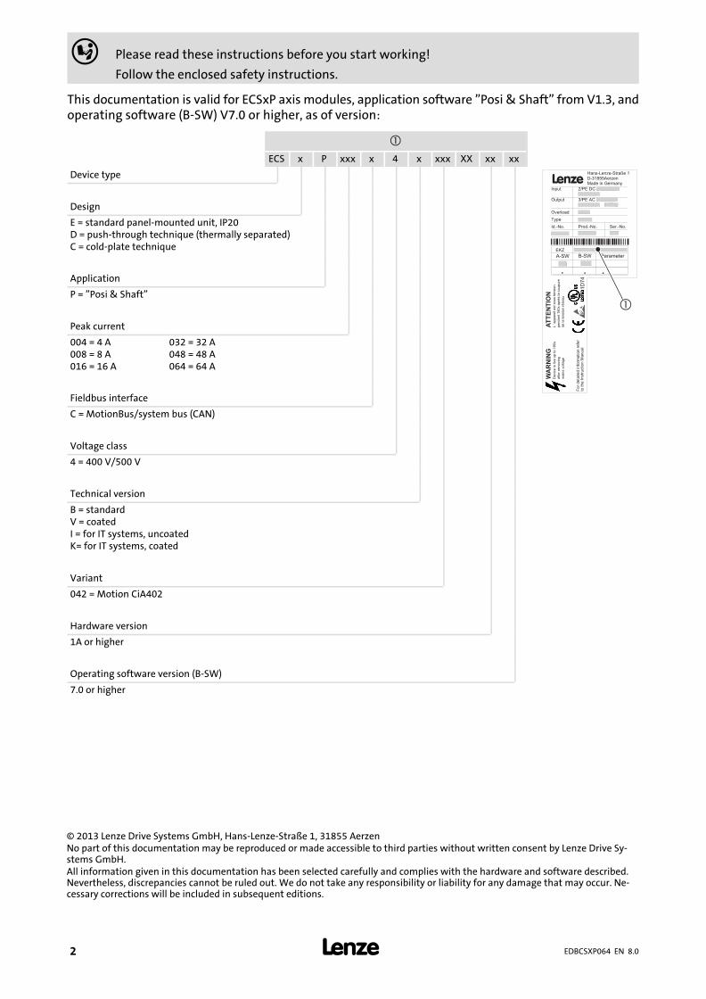
This documentation is valid for ECSxP axis modules, application software "Posi & Shaft" from V1.3, andoperating software (B−SW) V7.0 or higher, as of version:
�
ECS x P xxx x 4 x xxx XX xx xx
Device type �
AT
TE
NT
ION
L´a
pp
are
il e
st
so
us t
en
sio
n
pe
nd
an
t 1
80
s a
prè
s la
co
up
ure
de
la
te
nsio
n r
ése
au
WA
RN
ING
De
vic
e is liv
e u
p t
o 1
80
s
aft
er
rem
ovin
g
ma
ins v
olta
ge
�
Design
E = standard panel−mounted unit, IP20D = push−through technique (thermally separated)C = cold−plate technique
Application
P = "Posi & Shaft"
Peak current
004 = 4 A008 = 8 A016 = 16 A
032 = 32 A048 = 48 A064 = 64 A
Fieldbus interface
C = MotionBus/system bus (CAN)
Voltage class
4 = 400 V/500 V
Technical version
B = standardV = coatedI = for IT systems, uncoatedK= for IT systems, coated
Variant
042 = Motion CiA402
Hardware version
1A or higher
Operating software version (B−SW)
7.0 or higher
0Fig. 0Tab. 0
© 2013 Lenze Drive Systems GmbH, Hans−Lenze−Straße 1, 31855 AerzenNo part of this documentation may be reproduced or made accessible to third parties without written consent by Lenze Drive Sy-stems GmbH.All information given in this documentation has been selected carefully and complies with the hardware and software described.Nevertheless, discrepancies cannot be ruled out. We do not take any responsibility or liability for any damage that may occur. Ne-cessary corrections will be included in subsequent editions.

� 3EDBCSXP064 EN 8.0
ECSEA_003A
� 4 EDBCSXP064 EN 8.0
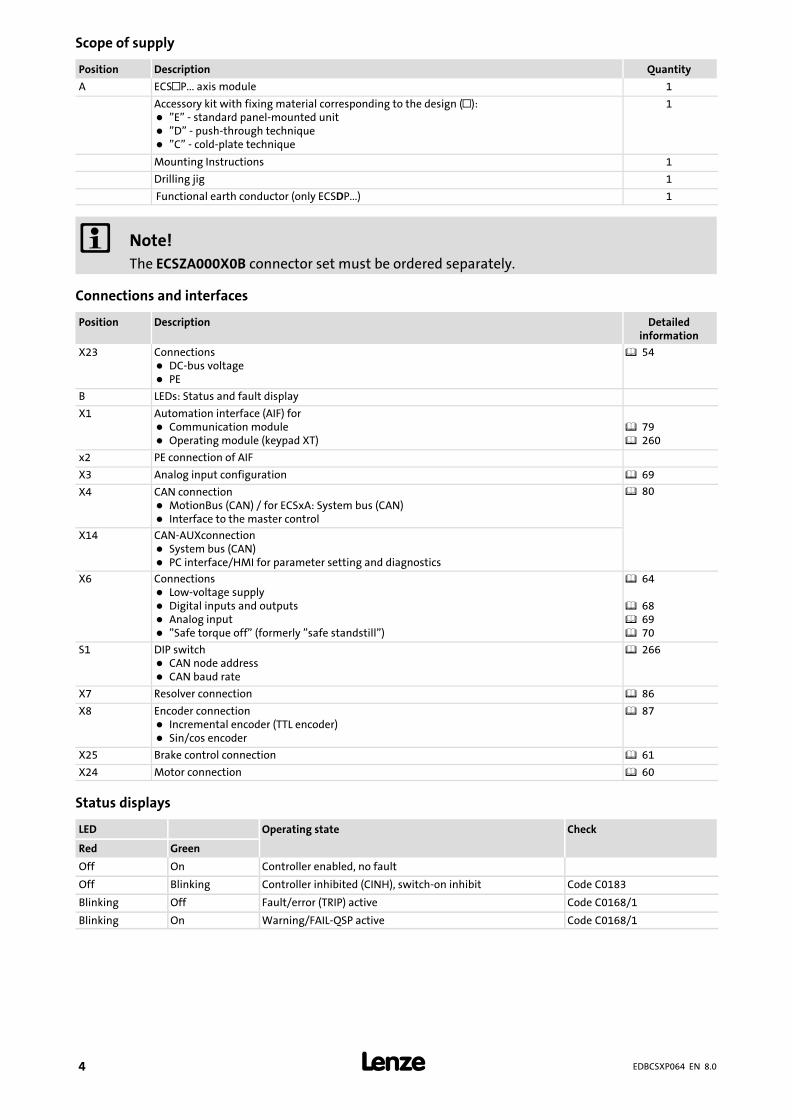
Scope of supply
Position Description Quantity
A ECS�P... axis module 1
Accessory kit with fixing material corresponding to the design (�):� "E" − standard panel−mounted unit� "D" − push−through technique� "C" − cold−plate technique
1
Mounting Instructions 1
Drilling jig 1
Functional earth conductor (only ECSDP...) 1
� Note!
The ECSZA000X0B connector set must be ordered separately.
Connections and interfaces
Position Description Detailedinformation
X23 Connections� DC−bus voltage� PE
� 54
B LEDs: Status and fault display
X1 Automation interface (AIF) for� Communication module� Operating module (keypad XT)
� 79� 260
x2 PE connection of AIF
X3 Analog input configuration � 69
X4 CAN connection� MotionBus (CAN) / for ECSxA: System bus (CAN)� Interface to the master control
� 80
X14 CAN−AUXconnection� System bus (CAN)� PC interface/HMI for parameter setting and diagnostics
X6 Connections� Low−voltage supply� Digital inputs and outputs� Analog input� "Safe torque off" (formerly "safe standstill")
� 64
� 68� 69� 70
S1 DIP switch� CAN node address� CAN baud rate
� 266
X7 Resolver connection � 86
X8 Encoder connection� Incremental encoder (TTL encoder)� Sin/cos encoder
� 87
X25 Brake control connection � 61
X24 Motor connection � 60
Status displays
LED Operating state Check
Red Green
Off On Controller enabled, no fault
Off Blinking Controller inhibited (CINH), switch−on inhibit Code C0183
Blinking Off Fault/error (TRIP) active Code C0168/1
Blinking On Warning/FAIL−QSP active Code C0168/1
Contents i
� 5EDBCSXP064 EN 8.0
1 Preface and general information 12 . . . . . . . . . . . . . . . . . . . . . . . . . . . . . . . . . . . . . . . . . . . .
1.1 About these Operating Instructions 12 . . . . . . . . . . . . . . . . . . . . . . . . . . . . . . . . . . . . .
1.1.1 Terminology used 13 . . . . . . . . . . . . . . . . . . . . . . . . . . . . . . . . . . . . . . . . . . . .
1.1.2 Code descriptions 14 . . . . . . . . . . . . . . . . . . . . . . . . . . . . . . . . . . . . . . . . . . . . .
1.2 Features of the ECSxP axis module 15 . . . . . . . . . . . . . . . . . . . . . . . . . . . . . . . . . . . . . .
1.3 Scope of supply 16 . . . . . . . . . . . . . . . . . . . . . . . . . . . . . . . . . . . . . . . . . . . . . . . . . . . . . .
1.4 Legal regulations 17 . . . . . . . . . . . . . . . . . . . . . . . . . . . . . . . . . . . . . . . . . . . . . . . . . . . . .
2 Safety instructions 18 . . . . . . . . . . . . . . . . . . . . . . . . . . . . . . . . . . . . . . . . . . . . . . . . . . . . . . . .
2.1 General safety and application notes for Lenze controllers 18 . . . . . . . . . . . . . . . . . .
2.2 Thermal motor monitoring 22 . . . . . . . . . . . . . . . . . . . . . . . . . . . . . . . . . . . . . . . . . . . .
2.2.1 Forced ventilated or naturally ventilated motors 23 . . . . . . . . . . . . . . . . . .
2.2.2 Self−ventilated motors 24 . . . . . . . . . . . . . . . . . . . . . . . . . . . . . . . . . . . . . . . . .
2.3 Residual hazards 26 . . . . . . . . . . . . . . . . . . . . . . . . . . . . . . . . . . . . . . . . . . . . . . . . . . . . .
2.4 Safety instructions for the installation according to UL 28 . . . . . . . . . . . . . . . . . . . . .
2.5 Notes used 29 . . . . . . . . . . . . . . . . . . . . . . . . . . . . . . . . . . . . . . . . . . . . . . . . . . . . . . . . . .
3 Technical data 30 . . . . . . . . . . . . . . . . . . . . . . . . . . . . . . . . . . . . . . . . . . . . . . . . . . . . . . . . . . . .
3.1 General data and operating conditions 30 . . . . . . . . . . . . . . . . . . . . . . . . . . . . . . . . .
3.2 Rated data 32 . . . . . . . . . . . . . . . . . . . . . . . . . . . . . . . . . . . . . . . . . . . . . . . . . . . . . . . . . .
3.3 Current characteristics 34 . . . . . . . . . . . . . . . . . . . . . . . . . . . . . . . . . . . . . . . . . . . . . . . .
3.3.1 Increased continuous current depending on the control factor 34 . . . . . . .
3.3.2 Device protection by current derating 37 . . . . . . . . . . . . . . . . . . . . . . . . . . . .
4 Mechanical installation 38 . . . . . . . . . . . . . . . . . . . . . . . . . . . . . . . . . . . . . . . . . . . . . . . . . . . .
4.1 Important notes 38 . . . . . . . . . . . . . . . . . . . . . . . . . . . . . . . . . . . . . . . . . . . . . . . . . . . . . .
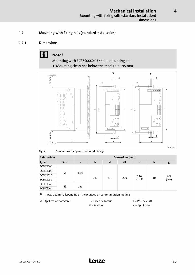
4.2 Mounting with fixing rails (standard installation) 39 . . . . . . . . . . . . . . . . . . . . . . . . .
4.2.1 Dimensions 39 . . . . . . . . . . . . . . . . . . . . . . . . . . . . . . . . . . . . . . . . . . . . . . . . . .
4.2.2 Mounting steps 40 . . . . . . . . . . . . . . . . . . . . . . . . . . . . . . . . . . . . . . . . . . . . . .
4.3 Mounting with thermal separation (push−through technique) 41 . . . . . . . . . . . . . . .
4.3.1 Dimensions 42 . . . . . . . . . . . . . . . . . . . . . . . . . . . . . . . . . . . . . . . . . . . . . . . . . .
4.3.2 Mounting steps 44 . . . . . . . . . . . . . . . . . . . . . . . . . . . . . . . . . . . . . . . . . . . . . .
4.4 Mounting in cold−plate design 45 . . . . . . . . . . . . . . . . . . . . . . . . . . . . . . . . . . . . . . . . . .
4.4.1 Dimensions 46 . . . . . . . . . . . . . . . . . . . . . . . . . . . . . . . . . . . . . . . . . . . . . . . . . .
4.4.2 Mounting steps 47 . . . . . . . . . . . . . . . . . . . . . . . . . . . . . . . . . . . . . . . . . . . . . .
Contentsi
� 6 EDBCSXP064 EN 8.0
5 Electrical installation 48 . . . . . . . . . . . . . . . . . . . . . . . . . . . . . . . . . . . . . . . . . . . . . . . . . . . . . . .
5.1 Installation according to EMC (installation of a CE−typical drive system) 48 . . . . . . .
5.2 Power terminals 51 . . . . . . . . . . . . . . . . . . . . . . . . . . . . . . . . . . . . . . . . . . . . . . . . . . . . .
5.2.1 Connection to the DC bus (+UG, −UG) 54 . . . . . . . . . . . . . . . . . . . . . . . . . . . .
5.2.2 Connection plan for mimimum wiring with internalbrake resistor 56 . . . . . . . . . . . . . . . . . . . . . . . . . . . . . . . . . . . . . . . . . . . . . . . .
5.2.3 Connection plan for mimimum wiring with externalbrake resistor 58 . . . . . . . . . . . . . . . . . . . . . . . . . . . . . . . . . . . . . . . . . . . . . . . .
5.2.4 Motor connection 60 . . . . . . . . . . . . . . . . . . . . . . . . . . . . . . . . . . . . . . . . . . . .
5.2.5 Motor holding brake connection 61 . . . . . . . . . . . . . . . . . . . . . . . . . . . . . . . .
5.2.6 Connection of an ECSxK... capacitor module (optional) 63 . . . . . . . . . . . . . .
5.3 Control terminals 64 . . . . . . . . . . . . . . . . . . . . . . . . . . . . . . . . . . . . . . . . . . . . . . . . . . . .
5.3.1 Digital inputs and outputs 68 . . . . . . . . . . . . . . . . . . . . . . . . . . . . . . . . . . . . .
5.3.2 Analog input 69 . . . . . . . . . . . . . . . . . . . . . . . . . . . . . . . . . . . . . . . . . . . . . . . . .
5.3.3 Safe torque off 70 . . . . . . . . . . . . . . . . . . . . . . . . . . . . . . . . . . . . . . . . . . . . . . .
5.4 Automation interface (AIF) 79 . . . . . . . . . . . . . . . . . . . . . . . . . . . . . . . . . . . . . . . . . . . . .
5.5 Wiring of system bus (CAN) 80 . . . . . . . . . . . . . . . . . . . . . . . . . . . . . . . . . . . . . . . . . . .
5.6 Wiring of the feedback system 85 . . . . . . . . . . . . . . . . . . . . . . . . . . . . . . . . . . . . . . . . .
5.6.1 Resolver connection 86 . . . . . . . . . . . . . . . . . . . . . . . . . . . . . . . . . . . . . . . . . . .
5.6.2 Encoder connection 87 . . . . . . . . . . . . . . . . . . . . . . . . . . . . . . . . . . . . . . . . . . .
5.6.3 Digital frequency input/output (encoder simulation) 90 . . . . . . . . . . . . . . .
6 Commissioning 92 . . . . . . . . . . . . . . . . . . . . . . . . . . . . . . . . . . . . . . . . . . . . . . . . . . . . . . . . . . .
6.1 Basic terms of positioning 92 . . . . . . . . . . . . . . . . . . . . . . . . . . . . . . . . . . . . . . . . . . . . .
6.1.1 Positioning 92 . . . . . . . . . . . . . . . . . . . . . . . . . . . . . . . . . . . . . . . . . . . . . . . . . .
6.1.2 Touch probe positioning 93 . . . . . . . . . . . . . . . . . . . . . . . . . . . . . . . . . . . . . . .
6.1.3 Positioning profile 94 . . . . . . . . . . . . . . . . . . . . . . . . . . . . . . . . . . . . . . . . . . . .
6.1.4 Positioning profile mode 95 . . . . . . . . . . . . . . . . . . . . . . . . . . . . . . . . . . . . . . .
6.1.5 Additional functions of the positioning profile (C3096/x) 96 . . . . . . . . . . .
6.1.6 Positioning profile parameters 97 . . . . . . . . . . . . . . . . . . . . . . . . . . . . . . . . . .
6.1.7 Setting of manual jog (inching mode) 101 . . . . . . . . . . . . . . . . . . . . . . . . . . . .
6.1.8 Homing 101 . . . . . . . . . . . . . . . . . . . . . . . . . . . . . . . . . . . . . . . . . . . . . . . . . . . . .
6.1.9 Measuring system for positioning 102 . . . . . . . . . . . . . . . . . . . . . . . . . . . . . . .
6.1.10 Machine parameters 103 . . . . . . . . . . . . . . . . . . . . . . . . . . . . . . . . . . . . . . . . . .
6.1.11 Electrical shaft ("EShaft") 107 . . . . . . . . . . . . . . . . . . . . . . . . . . . . . . . . . . . . . .
6.1.12 Device structure and interfaces to the higher−level control 108 . . . . . . . . . .
6.2 State control of the positioning drive 110 . . . . . . . . . . . . . . . . . . . . . . . . . . . . . . . . . . . .
6.2.1 Operating states 111 . . . . . . . . . . . . . . . . . . . . . . . . . . . . . . . . . . . . . . . . . . . . .
6.2.2 Conditions for state change (transitions) 113 . . . . . . . . . . . . . . . . . . . . . . . . .
6.3 Before you start 115 . . . . . . . . . . . . . . . . . . . . . . . . . . . . . . . . . . . . . . . . . . . . . . . . . . . . . .
Contents i
� 7EDBCSXP064 EN 8.0
6.4 Commissioning steps (overview) 116 . . . . . . . . . . . . . . . . . . . . . . . . . . . . . . . . . . . . . . . .
6.4.1 Basic settings with GDC 117 . . . . . . . . . . . . . . . . . . . . . . . . . . . . . . . . . . . . . . .
6.4.2 Set reference 119 . . . . . . . . . . . . . . . . . . . . . . . . . . . . . . . . . . . . . . . . . . . . . . . . .
6.4.3 Setting of manual jog (inching mode) 121 . . . . . . . . . . . . . . . . . . . . . . . . . . . .
6.4.4 Setting of homing 122 . . . . . . . . . . . . . . . . . . . . . . . . . . . . . . . . . . . . . . . . . . . .
6.4.5 Setting absolute positioning/relative continuous positioning 123 . . . . . . . .
6.5 Loading the Lenze setting 125 . . . . . . . . . . . . . . . . . . . . . . . . . . . . . . . . . . . . . . . . . . . . . .
6.6 Setting of mains data 126 . . . . . . . . . . . . . . . . . . . . . . . . . . . . . . . . . . . . . . . . . . . . . . . . .
6.6.1 Selecting the function of the charging current limitation 126 . . . . . . . . . . .
6.6.2 Setting the voltage thresholds 127 . . . . . . . . . . . . . . . . . . . . . . . . . . . . . . . . .
6.7 Entry of motor data for Lenze motors 128 . . . . . . . . . . . . . . . . . . . . . . . . . . . . . . . . . . . .
6.8 Holding brake configuration 130 . . . . . . . . . . . . . . . . . . . . . . . . . . . . . . . . . . . . . . . . . . .
6.9 Setting of the feedback system for position and speed control 132 . . . . . . . . . . . . . . .
6.9.1 Resolver as position and speed encoder 133 . . . . . . . . . . . . . . . . . . . . . . . . . .
6.9.2 Resolver as absolute value encoder 135 . . . . . . . . . . . . . . . . . . . . . . . . . . . . . .
6.9.3 TTL/SinCos encoder as position and speed encoder 136 . . . . . . . . . . . . . . . .
6.9.4 TTL/SinCos encoder as position encoder and resolver asspeed encoder 140 . . . . . . . . . . . . . . . . . . . . . . . . . . . . . . . . . . . . . . . . . . . . . . .
6.9.5 Absolute value encoder as position and speed encoder 145 . . . . . . . . . . . . .
6.9.6 Absolute value encoder as position encoder and resolver asspeed encoder 150 . . . . . . . . . . . . . . . . . . . . . . . . . . . . . . . . . . . . . . . . . . . . . . .
6.10 Select control interface (operating mode) 155 . . . . . . . . . . . . . . . . . . . . . . . . . . . . . . . .
6.11 Process data to the axis module (control word Ctrl1 and setpoints) 158 . . . . . . . . . .
6.11.1 Control word Ctrl1 159 . . . . . . . . . . . . . . . . . . . . . . . . . . . . . . . . . . . . . . . . . . . .
6.11.2 Setpoint data words to the controller(VelDirect, PosDirect, rx_par1..3) 160 . . . . . . . . . . . . . . . . . . . . . . . . . . . . . . . .
6.12 Process data from the axis module (status words and actual values) 161 . . . . . . . . .
6.12.1 Status word 1 (Stat1), status word 2 (Stat2) 161 . . . . . . . . . . . . . . . . . . . . . . .
6.12.2 Device status 163 . . . . . . . . . . . . . . . . . . . . . . . . . . . . . . . . . . . . . . . . . . . . . . . .
6.12.3 Monitor data words from the controller (tx_par1 und tx_par2) 164 . . . . . .
6.13 Entry of machine parameters 165 . . . . . . . . . . . . . . . . . . . . . . . . . . . . . . . . . . . . . . . . . .
6.14 Configuring the digital inputs and outputs 168 . . . . . . . . . . . . . . . . . . . . . . . . . . . . . . .
6.14.1 Digital inputs for operation with continuous positioning axis 170 . . . . . . . .
6.14.2 Digital inputs for operation with linear positioning axis 171 . . . . . . . . . . . .
6.14.3 Setting the polarity of digital inputs and outputs 172 . . . . . . . . . . . . . . . . . .
6.15 Setting of manual control parameters 173 . . . . . . . . . . . . . . . . . . . . . . . . . . . . . . . . . . .
6.15.1 Manual control to software limit position 175 . . . . . . . . . . . . . . . . . . . . . . . .
6.15.2 Manual control to hardware limit switch 175 . . . . . . . . . . . . . . . . . . . . . . . .
6.15.3 Retracting from hardware limit switches 176 . . . . . . . . . . . . . . . . . . . . . . . . .
Contentsi
� 8 EDBCSXP064 EN 8.0
6.16 Setting of homing parameters 177 . . . . . . . . . . . . . . . . . . . . . . . . . . . . . . . . . . . . . . . . . .
6.16.1 Setting homing modes 179 . . . . . . . . . . . . . . . . . . . . . . . . . . . . . . . . . . . . . . . .
6.16.2 Shifting the zero position with regard to the home position(offsets C3011, C3012) 187 . . . . . . . . . . . . . . . . . . . . . . . . . . . . . . . . . . . . . . . .
6.16.3 Example: Reference search with linear positioning axis 188 . . . . . . . . . . . .
6.16.4 Example: Reference search with continuous positioning axis 189 . . . . . . . .
6.17 Setting the positioning profile 191 . . . . . . . . . . . . . . . . . . . . . . . . . . . . . . . . . . . . . . . . . .
6.17.1 Selecting a positioning profile mode 191 . . . . . . . . . . . . . . . . . . . . . . . . . . . . .
6.17.2 "Point−to−point" positioning 193 . . . . . . . . . . . . . . . . . . . . . . . . . . . . . . . . . . . .
6.17.3 Touch probe positioning 194 . . . . . . . . . . . . . . . . . . . . . . . . . . . . . . . . . . . . . . .
6.17.4 Continuous constant travel 195 . . . . . . . . . . . . . . . . . . . . . . . . . . . . . . . . . . . .
6.17.5 Electrical shaft ("E−shaft") per digital frequency, MotionBs (CAN) orEtherCAT 196 . . . . . . . . . . . . . . . . . . . . . . . . . . . . . . . . . . . . . . . . . . . . . . . . . . . .
6.17.6 Homing 197 . . . . . . . . . . . . . . . . . . . . . . . . . . . . . . . . . . . . . . . . . . . . . . . . . . . . .
6.17.7 Direct positioning 198 . . . . . . . . . . . . . . . . . . . . . . . . . . . . . . . . . . . . . . . . . . . .
6.17.8 Positioning sequence for controller optimisation 200 . . . . . . . . . . . . . . . . . .
6.17.9 Setting of positioning profile parameters 201 . . . . . . . . . . . . . . . . . . . . . . . . .
6.17.10 Setting the profile parameter jerk time for S−shaped ramps 202 . . . . . . . . .
6.17.11 Additional functions of the positioning profile (C3096/x) 204 . . . . . . . . . . .
6.17.12 Activating the speed override 205 . . . . . . . . . . . . . . . . . . . . . . . . . . . . . . . . . . .
6.17.13 Activating the torque limitation after positioning 208 . . . . . . . . . . . . . . . . . .
6.17.14 Activating the profile continuation function 209 . . . . . . . . . . . . . . . . . . . . . .
6.17.15 Activate immediate profile change during positioning(Direct Change) 210 . . . . . . . . . . . . . . . . . . . . . . . . . . . . . . . . . . . . . . . . . . . . . .
6.18 Configuring the electrical shaft ("E−Shaft") 211 . . . . . . . . . . . . . . . . . . . . . . . . . . . . . . .
6.18.1 Setting the stretch factor (C3097 / C3098) 212 . . . . . . . . . . . . . . . . . . . . . . .
6.18.2 Electrical shaft via classical digital frequency coupling(digital frequency input X8) 215 . . . . . . . . . . . . . . . . . . . . . . . . . . . . . . . . . . . .
6.18.3 Electrical shaft via MotionBus (CAN) with ECSxP aselectrical shaft master 217 . . . . . . . . . . . . . . . . . . . . . . . . . . . . . . . . . . . . . . . . .
6.18.4 Electrical shaft via MotionBus (CAN) with PLC aselectrical shaft master 220 . . . . . . . . . . . . . . . . . . . . . . . . . . . . . . . . . . . . . . . . .
6.18.5 Electrical shaft via EtherCAT with PLC as electrical shaft master 224 . . . . . .
6.19 Starting positioning profiles (ProfEnable, profile number) 226 . . . . . . . . . . . . . . . . . .
6.19.1 Start of positioning profile via the "ProfEnable" control bit 227 . . . . . . . . .
6.19.2 Start of positioning profile by selecting a new profile number"PNoSet_x" 228 . . . . . . . . . . . . . . . . . . . . . . . . . . . . . . . . . . . . . . . . . . . . . . . . .
6.20 Setting the target position window (InTarget) 229 . . . . . . . . . . . . . . . . . . . . . . . . . . . .
6.21 Defining the window for standstill message 231 . . . . . . . . . . . . . . . . . . . . . . . . . . . . . .
6.22 Defining the dwell time 232 . . . . . . . . . . . . . . . . . . . . . . . . . . . . . . . . . . . . . . . . . . . . . . .
6.23 Following error monitoring (C3030, C3031) 233 . . . . . . . . . . . . . . . . . . . . . . . . . . . . . .
6.24 E−Shaft: Speed−dependent angular trimming 235 . . . . . . . . . . . . . . . . . . . . . . . . . . . . .
6.25 Software limit positions, limitation of the travel range 237 . . . . . . . . . . . . . . . . . . . . .

Contents i
� 9EDBCSXP064 EN 8.0
6.26 Evaluation of hardware limit switches 240 . . . . . . . . . . . . . . . . . . . . . . . . . . . . . . . . . . .
6.27 Controller enable (CINH = 0) 241 . . . . . . . . . . . . . . . . . . . . . . . . . . . . . . . . . . . . . . . . . . .
6.28 Quick stop (QSP) 243 . . . . . . . . . . . . . . . . . . . . . . . . . . . . . . . . . . . . . . . . . . . . . . . . . . . . .
6.29 Operation with motors from other manufacturers 244 . . . . . . . . . . . . . . . . . . . . . . . .
6.29.1 Entering motor data manually 244 . . . . . . . . . . . . . . . . . . . . . . . . . . . . . . . . . .
6.29.2 Checking the direction of rotation of the motor feedback system 246 . . . .
6.29.3 Adjusting current controller 247 . . . . . . . . . . . . . . . . . . . . . . . . . . . . . . . . . . . .
6.29.4 Effecting rotor position adjustment 249 . . . . . . . . . . . . . . . . . . . . . . . . . . . . .
6.30 Optimising the drive behaviour after start 252 . . . . . . . . . . . . . . . . . . . . . . . . . . . . . . . .
6.30.1 Speed controller adjustment 252 . . . . . . . . . . . . . . . . . . . . . . . . . . . . . . . . . . .
6.30.2 Adjustment of field controller and field weakening controller 254 . . . . . . .
6.30.3 Resolver adjustment 257 . . . . . . . . . . . . . . . . . . . . . . . . . . . . . . . . . . . . . . . . . .
7 Parameter setting 258 . . . . . . . . . . . . . . . . . . . . . . . . . . . . . . . . . . . . . . . . . . . . . . . . . . . . . . . . .
7.1 General information 258 . . . . . . . . . . . . . . . . . . . . . . . . . . . . . . . . . . . . . . . . . . . . . . . . .
7.2 Parameter setting with "Global Drive Control" (GDC) 259 . . . . . . . . . . . . . . . . . . . . . .
7.3 Parameter setting with the XT EMZ9371BC keypad 260 . . . . . . . . . . . . . . . . . . . . . . . .
7.3.1 Connecting the keypad 260 . . . . . . . . . . . . . . . . . . . . . . . . . . . . . . . . . . . . . . . .
7.3.2 Description of the display elements 261 . . . . . . . . . . . . . . . . . . . . . . . . . . . . .
7.3.3 Description of the function keys 263 . . . . . . . . . . . . . . . . . . . . . . . . . . . . . . . .
7.3.4 Changing and saving parameters 264 . . . . . . . . . . . . . . . . . . . . . . . . . . . . . . .
8 Configuration 265 . . . . . . . . . . . . . . . . . . . . . . . . . . . . . . . . . . . . . . . . . . . . . . . . . . . . . . . . . . . . .
8.1 Configuring MotionBus/system bus (CAN) 266 . . . . . . . . . . . . . . . . . . . . . . . . . . . . . . .
8.1.1 Setting CAN node address and baud rate 266 . . . . . . . . . . . . . . . . . . . . . . . . .
8.1.2 Individual addressing 271 . . . . . . . . . . . . . . . . . . . . . . . . . . . . . . . . . . . . . . . . .
8.1.3 Defining boot−up master in the drive system 273 . . . . . . . . . . . . . . . . . . . . . .
8.1.4 Setting of boot−up time/cycle time 274 . . . . . . . . . . . . . . . . . . . . . . . . . . . . . .
8.1.5 Executing a reset node 276 . . . . . . . . . . . . . . . . . . . . . . . . . . . . . . . . . . . . . . . .
8.1.6 Guiding angle selection and synchronisation via MotionBus (CAN) 277 . . .
8.1.7 Axis synchronisation (CAN synchronisation) 278 . . . . . . . . . . . . . . . . . . . . . .
8.1.8 Monitoring of the synchronisation (sync time slot) 281 . . . . . . . . . . . . . . . . .
8.1.9 Axis synchronisation via CAN 282 . . . . . . . . . . . . . . . . . . . . . . . . . . . . . . . . . . .
8.1.10 Axis synchronisation via terminal X6/DI1 283 . . . . . . . . . . . . . . . . . . . . . . . . .
8.2 Node guarding 284 . . . . . . . . . . . . . . . . . . . . . . . . . . . . . . . . . . . . . . . . . . . . . . . . . . . . . .
8.3 Diagnostics codes 286 . . . . . . . . . . . . . . . . . . . . . . . . . . . . . . . . . . . . . . . . . . . . . . . . . . . .
8.3.1 CAN bus status (C0359/C2459) 286 . . . . . . . . . . . . . . . . . . . . . . . . . . . . . . . . .
8.3.2 CAN telegram counter (C0360/2460) 287 . . . . . . . . . . . . . . . . . . . . . . . . . . . .
8.3.3 CAN bus load (C0361/2461) 288 . . . . . . . . . . . . . . . . . . . . . . . . . . . . . . . . . . . .
8.4 Remote parameterisation (gateway function) 289 . . . . . . . . . . . . . . . . . . . . . . . . . . . .

Contentsi
� 10 EDBCSXP064 EN 8.0
9 Monitoring functions 291 . . . . . . . . . . . . . . . . . . . . . . . . . . . . . . . . . . . . . . . . . . . . . . . . . . . . . .
9.1 Fault responses 292 . . . . . . . . . . . . . . . . . . . . . . . . . . . . . . . . . . . . . . . . . . . . . . . . . . . . . .
9.2 Overview of monitoring functions 293 . . . . . . . . . . . . . . . . . . . . . . . . . . . . . . . . . . . . . .
9.3 Configuring monitoring functions 297 . . . . . . . . . . . . . . . . . . . . . . . . . . . . . . . . . . . . . .
9.3.1 Monitoring times for process data input objects 297 . . . . . . . . . . . . . . . . . . .
9.3.2 Time−out monitoring for activated remote parameterisation 299 . . . . . . . .
9.3.3 Short circuit monitoring (OC1) 300 . . . . . . . . . . . . . . . . . . . . . . . . . . . . . . . . . .
9.3.4 Earth fault monitoring (OC2) 300 . . . . . . . . . . . . . . . . . . . . . . . . . . . . . . . . . . .
9.3.5 Motor temperature monitoring (OH3, OH7) 301 . . . . . . . . . . . . . . . . . . . . . .
9.3.6 Heatsink temperature monitoring (OH, OH4) 303 . . . . . . . . . . . . . . . . . . . . .
9.3.7 Monitoring of internal device temperature (OH1, OH5) 304 . . . . . . . . . . . . .
9.3.8 Function monitoring of thermal sensors (H10, H11) 305 . . . . . . . . . . . . . . . .
9.3.9 Current load of controller (I x t monitoring: OC5, OC7) 306 . . . . . . . . . . . . . .
9.3.10 Current load of motor (I2 x t monitoring: OC6, OC8) 309 . . . . . . . . . . . . . . . .
9.3.11 DC−bus voltage monitoring (OU, LU) 313 . . . . . . . . . . . . . . . . . . . . . . . . . . . . .
9.3.12 Voltage supply monitoring − control electronics (U15) 316 . . . . . . . . . . . . . .
9.3.13 Motor phase failure monitoring (LP1) 316 . . . . . . . . . . . . . . . . . . . . . . . . . . . .
9.3.14 Monitoring of the resolver cable (Sd2) 317 . . . . . . . . . . . . . . . . . . . . . . . . . . .
9.3.15 Motor temperature sensor monitoring (Sd6) 318 . . . . . . . . . . . . . . . . . . . . . .
9.3.16 Monitoring of the absolute value encoder initialisation (Sd7) 319 . . . . . . . .
9.3.17 Sin/cos signal monitoring (Sd8) 320 . . . . . . . . . . . . . . . . . . . . . . . . . . . . . . . . .
9.3.18 Monitoring of the speed system deviation (nErr) 321 . . . . . . . . . . . . . . . . . . .
9.3.19 Monitoring of max. system speed (NMAX) 322 . . . . . . . . . . . . . . . . . . . . . . . .
9.3.20 Monitoring of the rotor position adjustment (PL) 323 . . . . . . . . . . . . . . . . . .
10 Diagnostics 324 . . . . . . . . . . . . . . . . . . . . . . . . . . . . . . . . . . . . . . . . . . . . . . . . . . . . . . . . . . . . . . .
10.1 Diagnostics with Global Drive Control (GDC) 324 . . . . . . . . . . . . . . . . . . . . . . . . . . . . . .
10.2 Diagnostics with Global Drive Oscilloscope (GDO) 326 . . . . . . . . . . . . . . . . . . . . . . . . .
10.2.1 GDO buttons 327 . . . . . . . . . . . . . . . . . . . . . . . . . . . . . . . . . . . . . . . . . . . . . . . . .
10.2.2 Diagnostics with GDO 328 . . . . . . . . . . . . . . . . . . . . . . . . . . . . . . . . . . . . . . . . .
10.3 Diagnostics with the XT EMZ9371BC keypad 333 . . . . . . . . . . . . . . . . . . . . . . . . . . . . .
10.4 Diagnostics with PCAN−View 334 . . . . . . . . . . . . . . . . . . . . . . . . . . . . . . . . . . . . . . . . . . .
10.4.1 Monitoring of telegram traffic on the CAN bus 334 . . . . . . . . . . . . . . . . . . . .
10.4.2 Setting all CAN nodes to the "Operational" status 336 . . . . . . . . . . . . . . . . .
Contents i
� 11EDBCSXP064 EN 8.0
11 Troubleshooting and fault elimination 337 . . . . . . . . . . . . . . . . . . . . . . . . . . . . . . . . . . . . . . .
11.1 Fault analysis 337 . . . . . . . . . . . . . . . . . . . . . . . . . . . . . . . . . . . . . . . . . . . . . . . . . . . . . . . .
11.1.1 Fault analysis via the LED display 337 . . . . . . . . . . . . . . . . . . . . . . . . . . . . . . . .
11.1.2 Fault analysis with keypad XT EMZ9371BC 337 . . . . . . . . . . . . . . . . . . . . . . .
11.1.3 Fault analysis with the history buffer 338 . . . . . . . . . . . . . . . . . . . . . . . . . . . .
11.1.4 Fault analysis via LECOM status words (C0150/C0155) 340 . . . . . . . . . . . . .
11.2 Malfunction of the drive 342 . . . . . . . . . . . . . . . . . . . . . . . . . . . . . . . . . . . . . . . . . . . . . . .
11.3 Fault messages 343 . . . . . . . . . . . . . . . . . . . . . . . . . . . . . . . . . . . . . . . . . . . . . . . . . . . . . .
11.3.1 Causes and remedies 343 . . . . . . . . . . . . . . . . . . . . . . . . . . . . . . . . . . . . . . . . . .
11.3.2 Reset fault messages (TRIP−RESET) 352 . . . . . . . . . . . . . . . . . . . . . . . . . . . . . . .
12 Appendix 353 . . . . . . . . . . . . . . . . . . . . . . . . . . . . . . . . . . . . . . . . . . . . . . . . . . . . . . . . . . . . . . . .
12.1 Code table 353 . . . . . . . . . . . . . . . . . . . . . . . . . . . . . . . . . . . . . . . . . . . . . . . . . . . . . . . . . .
12.2 General information about the system bus (CAN) 411 . . . . . . . . . . . . . . . . . . . . . . . . .
12.3 Communication with MotionBus/system bus (CAN) 412 . . . . . . . . . . . . . . . . . . . . . . .
12.3.1 Structure of the CAN data telegram 412 . . . . . . . . . . . . . . . . . . . . . . . . . . . . .
12.3.2 Communication phases of the CAN network (NMT) 414 . . . . . . . . . . . . . . . .
12.3.3 Process data transfer 417 . . . . . . . . . . . . . . . . . . . . . . . . . . . . . . . . . . . . . . . . . .
12.3.4 Parameter data transfer 423 . . . . . . . . . . . . . . . . . . . . . . . . . . . . . . . . . . . . . . .
12.3.5 Addressing of the parameter and process data objects 429 . . . . . . . . . . . . .
12.4 Overview of accessories 431 . . . . . . . . . . . . . . . . . . . . . . . . . . . . . . . . . . . . . . . . . . . . . . .
12.4.1 Connector sets 431 . . . . . . . . . . . . . . . . . . . . . . . . . . . . . . . . . . . . . . . . . . . . . . .
12.4.2 Shield mounting kit 431 . . . . . . . . . . . . . . . . . . . . . . . . . . . . . . . . . . . . . . . . . . .
12.4.3 Components for operation and communication 432 . . . . . . . . . . . . . . . . . . .
12.4.4 Brake resistor 433 . . . . . . . . . . . . . . . . . . . . . . . . . . . . . . . . . . . . . . . . . . . . . . . .
12.4.5 Mains fuses 435 . . . . . . . . . . . . . . . . . . . . . . . . . . . . . . . . . . . . . . . . . . . . . . . . . .
12.4.6 Mains chokes 436 . . . . . . . . . . . . . . . . . . . . . . . . . . . . . . . . . . . . . . . . . . . . . . . .
12.4.7 RFI filters 437 . . . . . . . . . . . . . . . . . . . . . . . . . . . . . . . . . . . . . . . . . . . . . . . . . . . .
13 Index 438 . . . . . . . . . . . . . . . . . . . . . . . . . . . . . . . . . . . . . . . . . . . . . . . . . . . . . . . . . . . . . . . . . . . .
Preface and general informationAbout these Operating Instructions
1
� 12 EDBCSXP064 EN 8.0
1 Preface and general information
1.1 About these Operating Instructions
These Operating Instructions will assist you in connecting and commissioning the ECSxP...axis modules.
They contain safety instructions which must be observed!
All persons working on and with the ECSxP... axis modules must have the OperatingInstructions available and must observe the information and notes relevant for their work.
The Operating Instructions must always be in a complete and perfectly readable state.
Preface and general informationAbout these Operating Instructions
Terminology used
1
� 13EDBCSXP064 EN 8.0
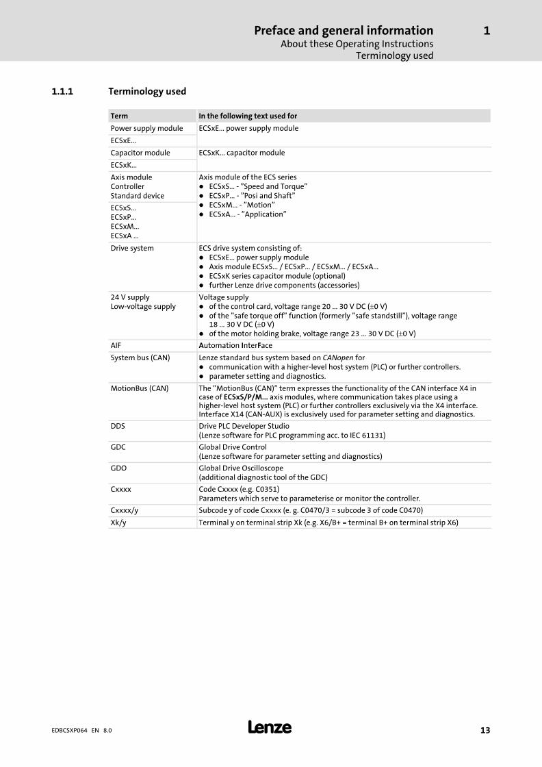
1.1.1 Terminology used
Term In the following text used for
Power supply module ECSxE... power supply module
ECSxE...
Capacitor module ECSxK... capacitor module
ECSxK...
Axis moduleControllerStandard device
Axis module of the ECS series� ECSxS... − "Speed and Torque"� ECSxP... − "Posi and Shaft"� ECSxM... − "Motion"� ECSxA... − "Application"
ECSxS...ECSxP...ECSxM...ECSxA ...
Drive system ECS drive system consisting of:� ECSxE... power supply module� Axis module ECSxS... / ECSxP... / ECSxM... / ECSxA...� ECSxK series capacitor module (optional)� further Lenze drive components (accessories)
24 V supplyLow−voltage supply
Voltage supply� of the control card, voltage range 20 ... 30 V DC (�0 V)� of the "safe torque off" function (formerly "safe standstill"), voltage range
18 ... 30 V DC (�0 V)� of the motor holding brake, voltage range 23 ... 30 V DC (�0 V)
AIF Automation InterFace
System bus (CAN) Lenze standard bus system based on CANopen for� communication with a higher−level host system (PLC) or further controllers.� parameter setting and diagnostics.
MotionBus (CAN) The "MotionBus (CAN)" term expresses the functionality of the CAN interface X4 incase of ECSxS/P/M... axis modules, where communication takes place using ahigher−level host system (PLC) or further controllers exclusively via the X4 interface.Interface X14 (CAN−AUX) is exclusively used for parameter setting and diagnostics.
DDS Drive PLC Developer Studio(Lenze software for PLC programming acc. to IEC 61131)
GDC Global Drive Control(Lenze software for parameter setting and diagnostics)
GDO Global Drive Oscilloscope(additional diagnostic tool of the GDC)
Cxxxx Code Cxxxx (e.g. C0351)Parameters which serve to parameterise or monitor the controller.
Cxxxx/y Subcode y of code Cxxxx (e. g. C0470/3 = subcode 3 of code C0470)
Xk/y Terminal y on terminal strip Xk (e.g. X6/B+ = terminal B+ on terminal strip X6)

Preface and general informationAbout these Operating InstructionsCode descriptions
1
� 14 EDBCSXP064 EN 8.0
1.1.2 Code descriptions
Lenze codes are described in the form of tables with the following structure:
Column Abbreviation Meaning
No. Cxxxx Code no. Cxxxx
1 Subcode 1 of Cxxxx
2 Subcode 2 of Cxxxx
Cxxxx Changed input value of the code or subcode is accepted after pressing��.
[Cxxxx] Changed input value of the code or subcode is accepted after pressing�� when the controller is inhibited.
Name LCD display of the keypad XT EMZ9371BC
Lenze/{Appl.} x Lenze setting:� Value at the time of delivery or after loading the Lenze setting using
C0002.
{xxx...} Different application initialisation value� Value at the time of delivery� After loading the Lenze setting using C0002, the application
initialisation value is overwritten with the Lenze setting.� The application initialisation values can be restored by loading the
application software with "Global Drive Loader" (GDL).
� The "Important" column contains further information
Selection 1 {%} 99 minimum value {unit} maximum value
IMPORTANT Short code description
Example
Code Possible settings IMPORTANT
No. Designation Lenze/{Appl.}
Selection
C0003 Par save 0 Non−volatile saving of parameterset
0 No response
1 Save parameter set
C1192 Selection of resistancecharacteristic for PTC
1 Char.: OHM 1000{0}
0 {1 �} 30000 PTC characteristic: resistance R1 at T1
2 Char.: OHM 2225 PTC characteristic: resistance R2 at T2
Preface and general informationFeatures of the ECSxP
1
� 15EDBCSXP064 EN 8.0
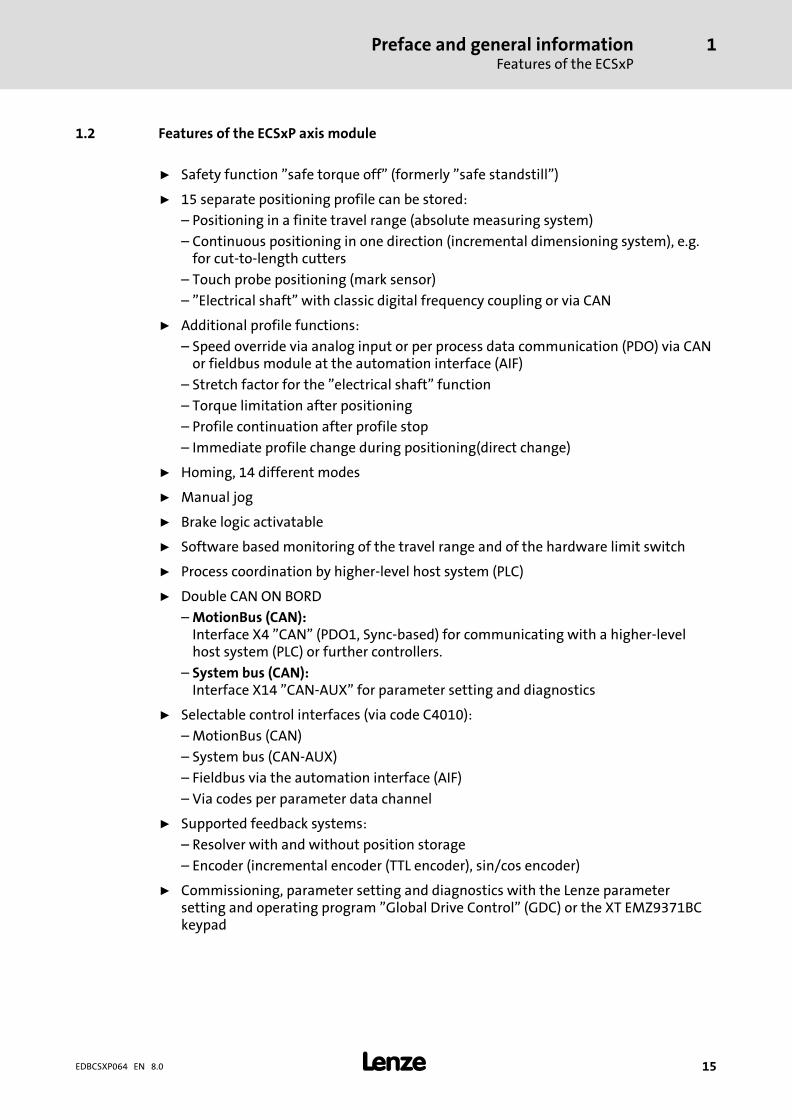
1.2 Features of the ECSxP axis module
ƒ Safety function "safe torque off" (formerly "safe standstill")
ƒ 15 separate positioning profile can be stored:
– Positioning in a finite travel range (absolute measuring system)
– Continuous positioning in one direction (incremental dimensioning system), e.g.for cut−to−length cutters
– Touch probe positioning (mark sensor)
– "Electrical shaft" with classic digital frequency coupling or via CAN
ƒ Additional profile functions:
– Speed override via analog input or per process data communication (PDO) via CANor fieldbus module at the automation interface (AIF)
– Stretch factor for the "electrical shaft" function
– Torque limitation after positioning
– Profile continuation after profile stop
– Immediate profile change during positioning(direct change)
ƒ Homing, 14 different modes
ƒ Manual jog
ƒ Brake logic activatable
ƒ Software based monitoring of the travel range and of the hardware limit switch
ƒ Process coordination by higher−level host system (PLC)
ƒ Double CAN ON BORD
– MotionBus (CAN):Interface X4 "CAN" (PDO1, Sync−based) for communicating with a higher−levelhost system (PLC) or further controllers.
– System bus (CAN):Interface X14 "CAN−AUX" for parameter setting and diagnostics
ƒ Selectable control interfaces (via code C4010):
– MotionBus (CAN)
– System bus (CAN−AUX)
– Fieldbus via the automation interface (AIF)
– Via codes per parameter data channel
ƒ Supported feedback systems:
– Resolver with and without position storage
– Encoder (incremental encoder (TTL encoder), sin/cos encoder)
ƒ Commissioning, parameter setting and diagnostics with the Lenze parametersetting and operating program "Global Drive Control" (GDC) or the XT EMZ9371BCkeypad
Preface and general informationScope of supply
1
� 16 EDBCSXP064 EN 8.0
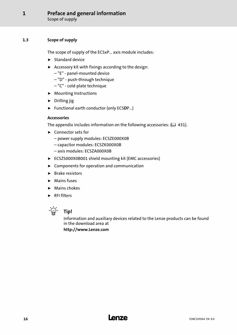
1.3 Scope of supply
The scope of supply of the ECSxP... axis module includes:
ƒ Standard device
ƒ Accessory kit with fixings according to the design:
– "E" − panel−mounted device
– "D" − push−through technique
– "C" − cold−plate technique
ƒ Mounting Instructions
ƒ Drilling jig
ƒ Functional earth conductor (only ECSDP...)
Accessories
The appendix includes information on the following accessories: ( 431).
ƒ Connector sets for
– power supply modules: ECSZE000X0B
– capacitor modules: ECSZK000X0B
– axis modules: ECSZA000X0B
ƒ ECSZS000X0B001 shield mounting kit (EMC accessories)
ƒ Components for operation and communication
ƒ Brake resistors
ƒ Mains fuses
ƒ Mains chokes
ƒ RFI filters
� Tip!
Information and auxiliary devices related to the Lenze products can be foundin the download area at
http://www.Lenze.com

Preface and general informationLegal regulations
1
� 17EDBCSXP064 EN 8.0
1.4 Legal regulations
Identification Nameplate CE designation Manufacturer
Lenze controllers areunambiguously designated by thecontents of the nameplate.
Conforms to the EC Low−VoltageDirective
Lenze Automation GmbHGrünstraße 36D−40667 Meerbusch
Application asdirected
ECSxP... axis modules� must only be operated under the conditions prescribed in these Instructions.� are components
– for open and closed loop control of variable speed drives with PM synchronous motors and asynchronousmotors.
– for installation into a machine– for assembly with other components to form a machine.
� are electrical equipment for the installation in control cabinets or similar closed operating areas.� comply with the protective requirements of the EC Low−Voltage Directive.� are not machines for the purpose of the EC Machinery Directive.� are not to be used as domestic appliances, but for industrial purposes only.Drive systems with ECSxP... axis modules� comply with the EC Directive "Electromagnetic compatibility" if they are installed according to the guidelines
of CE−typical drive systems.� can be used
– at public and non−public mains.– in industrial premises.
� The user is responsible for the compliance of his application with the EC directives.Any other use shall be deemed inappropriate!
Liability � The information, data and notes in these Instructions met the state of the art at the time of printing. Claimson modifications referring to axis modules and components which have already been supplied cannot bederived from the information, illustrations and descriptions given in these Instructions.
� The specifications, processes, and circuitry described in these Instructions are for guidance only and must beadapted to your own specific application. Lenze does not take responsibility for the suitability of the processand circuit proposals.
� Lenze does not accept any liability for damages and failures caused by:– Disregarding the Operating Instructions– Unauthorised modifications to the axis module– Operating errors– Improper working on and with the axis module
Warranty � Terms of warranty: See terms of sales and delivery of Lenze Drive Systems GmbH.� Warranty claims must be made to Lenze immediately after detecting the deficiency or fault.� The warranty is void in all cases where liability claims cannot be made.
Safety instructionsGeneral safety and application notes for Lenze controllers
2
� 18 EDBCSXP064 EN 8.0
2 Safety instructions
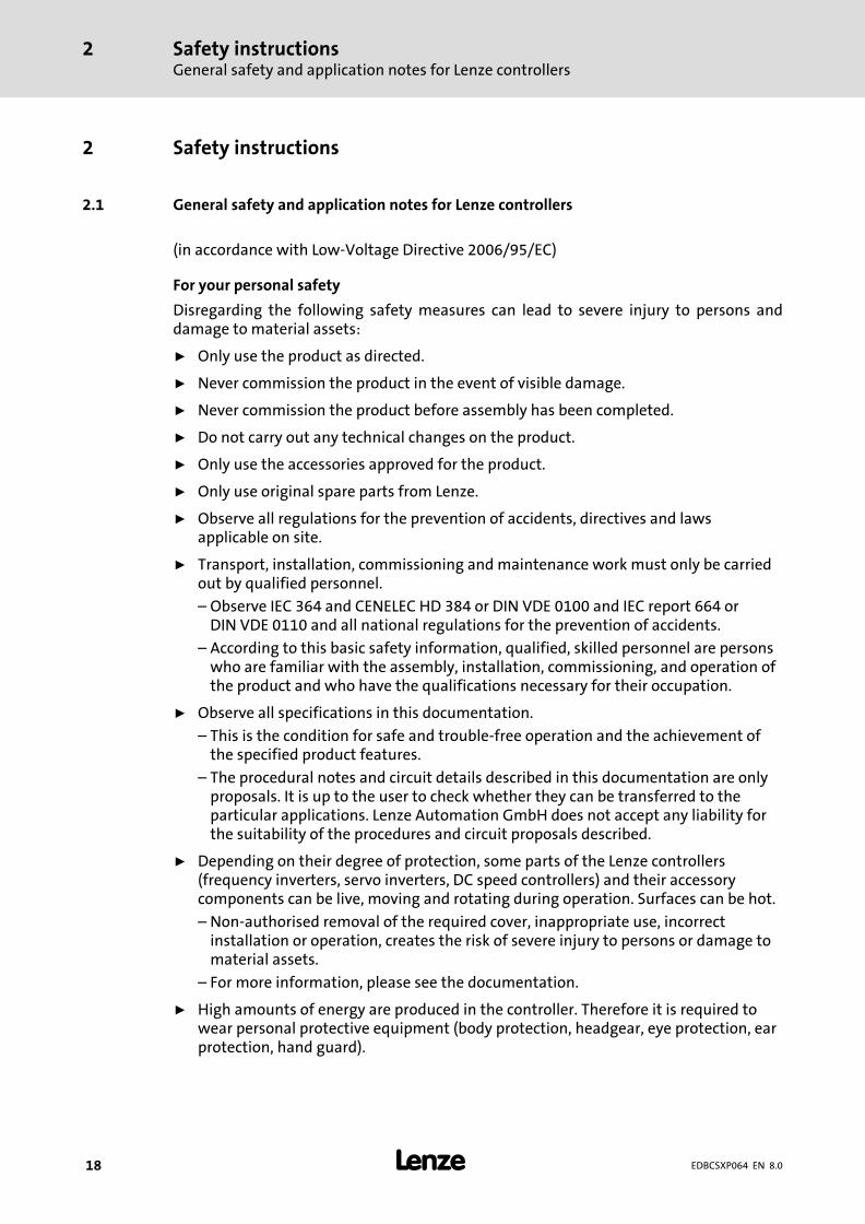
2.1 General safety and application notes for Lenze controllers
(in accordance with Low−Voltage Directive 2006/95/EC)
For your personal safety
Disregarding the following safety measures can lead to severe injury to persons anddamage to material assets:
ƒ Only use the product as directed.
ƒ Never commission the product in the event of visible damage.
ƒ Never commission the product before assembly has been completed.
ƒ Do not carry out any technical changes on the product.
ƒ Only use the accessories approved for the product.
ƒ Only use original spare parts from Lenze.
ƒ Observe all regulations for the prevention of accidents, directives and lawsapplicable on site.
ƒ Transport, installation, commissioning and maintenance work must only be carriedout by qualified personnel.
– Observe IEC 364 and CENELEC HD 384 or DIN VDE 0100 and IEC report 664 orDIN VDE 0110 and all national regulations for the prevention of accidents.
– According to this basic safety information, qualified, skilled personnel are personswho are familiar with the assembly, installation, commissioning, and operation ofthe product and who have the qualifications necessary for their occupation.
ƒ Observe all specifications in this documentation.
– This is the condition for safe and trouble−free operation and the achievement ofthe specified product features.
– The procedural notes and circuit details described in this documentation are onlyproposals. It is up to the user to check whether they can be transferred to theparticular applications. Lenze Automation GmbH does not accept any liability forthe suitability of the procedures and circuit proposals described.
ƒ Depending on their degree of protection, some parts of the Lenze controllers(frequency inverters, servo inverters, DC speed controllers) and their accessorycomponents can be live, moving and rotating during operation. Surfaces can be hot.
– Non−authorised removal of the required cover, inappropriate use, incorrectinstallation or operation, creates the risk of severe injury to persons or damage tomaterial assets.
– For more information, please see the documentation.
ƒ High amounts of energy are produced in the controller. Therefore it is required towear personal protective equipment (body protection, headgear, eye protection, earprotection, hand guard).

Safety instructionsGeneral safety and application notes for Lenze controllers
2
� 19EDBCSXP064 EN 8.0
Application as directed
Controllers are components which are designed for installation in electrical systems ormachines. They are not to be used as domestic appliances, but only for industrial purposesaccording to EN 61000−3−2.
When controllers are installed into machines, commissioning (i.e. starting of the operationas directed) is prohibited until it is proven that the machine complies with the regulationsof the EC Directive 2006/42/EC (Machinery Directive); EN 60204 must be observed.
Commissioning (i.e. starting of the operation as directed) is only allowed when there iscompliance with the EMC Directive (2004/108/EC).
The controllers meet the requirements of the Low−Voltage Directive 2006/95/EC. Theharmonised standard EN 61800−5−1 applies to the controllers.
The technical data and supply conditions can be obtained from the nameplate and thedocumentation. They must be strictly observed.
Warning: Controllers are products which can be installed in drive systems of category C2according to EN 61800−3. These products can cause radio interferences in residential areas.In this case, special measures can be necessary.
Transport, storage
Please observe the notes on transport, storage, and appropriate handling.
Observe the climatic conditions according to the technical data.
Installation
The controllers must be installed and cooled according to the instructions given in thecorresponding documentation.
The ambient air must not exceed degree of pollution 2 according to EN 61800−5−1.
Ensure proper handling and avoid excessive mechanical stress. Do not bend anycomponents and do not change any insulation distances during transport or handling. Donot touch any electronic components and contacts.
Controllers contain electrostatic sensitive devices which can easily be damaged byinappropriate handling. Do not damage or destroy any electrical components since thismight endanger your health!
Safety instructionsGeneral safety and application notes for Lenze controllers
2
� 20 EDBCSXP064 EN 8.0
Electrical connection
When working on live controllers, observe the applicable national regulations for theprevention of accidents (e.g. VBG 4).
The electrical installation must be carried out according to the appropriate regulations(e.g. cable cross−sections, fuses, PE connection). Additional information can be obtainedfrom the documentation.
This documentation contains information on installation in compliance with EMC(shielding, earthing, filter, and cables). These notes must also be observed for CE−markedcontrollers. The manufacturer of the system is responsible for compliance with the limitvalues demanded by EMC legislation. The controllers must be installed in housings (e.g.control cabinets) to meet the limit values for radio interferences valid at the site ofinstallation. The housings must enable an EMC−compliant installation. Observe inparticular that e.g. the control cabinet doors have a circumferential metal connection tothe housing. Reduce housing openings and cutouts to a minimum.
Lenze controllers may cause a DC current in the PE conductor. If a residual current device(RCD) is used for protection against direct or indirect contact for a controller withthree−phase supply, only a residual current device (RCD) of type B is permissible on thesupply side of the controller. If the controller has a single−phase supply, a residual currentdevice (RCD) of type A is also permissible. Apart from using a residual current device (RCD),other protective measures can be taken as well, e.g. electrical isolation by double orreinforced insulation or isolation from the supply system by means of a transformer.
Operation
If necessary, systems including controllers must be equipped with additional monitoringand protection devices according to the valid safety regulations (e.g. law on technicalequipment, regulations for the prevention of accidents). The controllers can be adapted toyour application. Please observe the corresponding information given in thedocumentation.
After the controller has been disconnected from the supply voltage, all live componentsand power terminals must not be touched immediately because capacitors can still becharged. Please observe the corresponding stickers on the controller.
All protection covers and doors must be shut during operation.
Notes for UL−approved systems with integrated controllers: UL warnings are notes thatonly apply to UL systems. The documentation contains special UL notes.
Safety instructionsGeneral safety and application notes for Lenze controllers
2
� 21EDBCSXP064 EN 8.0
Safety functions
Certain controller versions support safety functions (e.g. "Safe torque off", formerly "Safestandstill") according to the requirements of the EC Directive 2006/42/EC (MachineryDirective). The notes on the integrated safety system provided in this documentation mustbe observed.
Maintenance and servicing
The controllers do not require any maintenance if the prescribed operating conditions areobserved.
Disposal
Recycle metal and plastic materials. Ensure professional disposal of assembled PCBs.
The product−specific safety and application notes given in these instructions must beobserved!

Safety instructionsThermal motor monitoring
2
� 22 EDBCSXP064 EN 8.0
2.2 Thermal motor monitoring
� Note!
ƒ I2 x t monitoring is based on a mathematical model which calculates athermal motor load from the detected motor currents.
ƒ The calculated motor load is saved when the mains is switched.
ƒ The function is UL−certified, i.e. no additional protective measures arerequired for the motor in UL−approved systems.
ƒ However, I2 x t monitoring is no full motor protection as other influences onthe motor load could not be detected as for instance changed coolingconditions (e.g. interrupted or too warm cooling air flow).
Die I2 x t load of the motor is displayed in C0066.
The thermal loading capacity of the motor is expressed by the thermal motor timeconstant (�, C0128). Find the value in the rated motor data or contact the manufacturer ofthe motor.
The I2 x t monitoring has been designed such that it will be activated after 179 s in theevent of a motor with a thermal motor time constant of 5 minutes (Lenze setting C0128),a motor current of 1.5 x IN and a trigger threshold of 100 %.
Two adjustable trigger thresholds provide for different responses.
ƒ Adjustable response OC8 (TRIP, warning, off).
– The trigger threshold is set in C0127.
– The response is set in C0606.
– The response OC8, for instance, can be used for an advance warning.
ƒ Fixed response OC6−TRIP.
– The trigger threshold is set in C0120.
Behaviour of the I2 x t monitoring Condition
The I2 x t monitoring is deactivated.C0066 is set = 0 % andMCTRL−LOAD−I2XT is set = 0.00 %.
When C0120 = 0 % and C0127 = 0 %, set controllerinhibit.
I2 x t monitoring is stopped.The current value in C0066 and at theMCTRL−LOAD−I2XT output is frozen.
When C0120 = 0 % and C0127 = 0 %, set controllerenable.
I2 x t monitoring is deactivated.The motor load is displayed in C0066.
Set C0606 = 3 (off) and C0127 > 0 %.
� Note!
An error message OC6 or OC8 can only be reset if the I2 x t load falls below theset trigger threshold by 5 %.
Safety instructionsThermal motor monitoring
Forced ventilated or naturally ventilated motors
2
� 23EDBCSXP064 EN 8.0
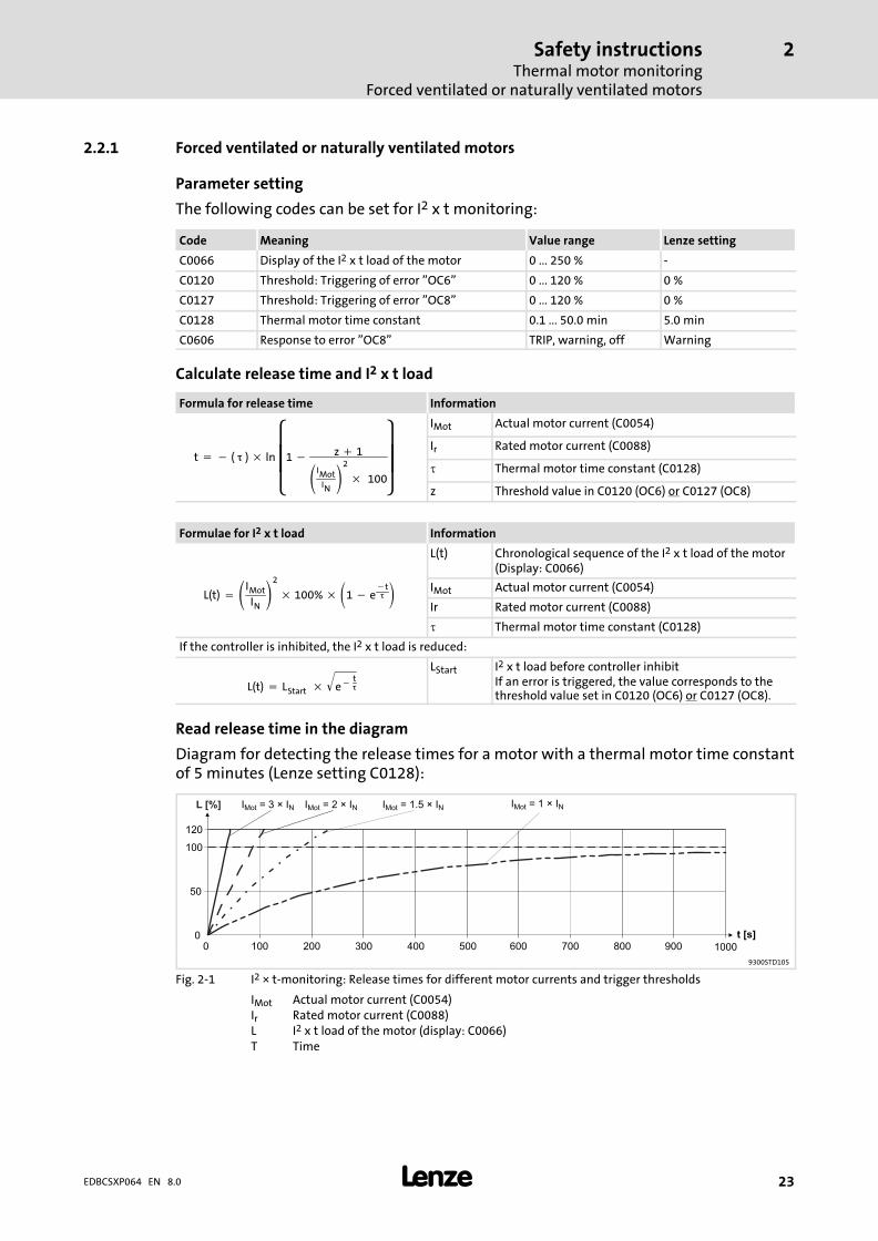
2.2.1 Forced ventilated or naturally ventilated motors
Parameter setting
The following codes can be set for I2 x t monitoring:
Code Meaning Value range Lenze setting
C0066 Display of the I2 x t load of the motor 0 ... 250 % −
C0120 Threshold: Triggering of error "OC6" 0 ... 120 % 0 %
C0127 Threshold: Triggering of error "OC8" 0 ... 120 % 0 %
C0128 Thermal motor time constant 0.1 ... 50.0 min 5.0 min
C0606 Response to error "OC8" TRIP, warning, off Warning
Calculate release time and I2 x t load
Formula for release time Information
t � � (���) � ln����
�1 � z � 1
IMotIN2
�� 100
���
�
IMot Actual motor current (C0054)
Ir Rated motor current (C0088)
� Thermal motor time constant (C0128)
z Threshold value in C0120 (OC6) or C0127 (OC8)
Formulae for I2 x t load Information
L(t) � IMot
IN2
� 100% �1 � e�t�
L(t) Chronological sequence of the I2 x t load of the motor(Display: C0066)
IMot Actual motor current (C0054)
Ir Rated motor current (C0088)
� Thermal motor time constant (C0128)
If the controller is inhibited, the I2 x t load is reduced:
L(t) � LStart� � e��t�
� LStart I2 x t load before controller inhibit
If an error is triggered, the value corresponds to thethreshold value set in C0120 (OC6) or C0127 (OC8).
Read release time in the diagram
Diagram for detecting the release times for a motor with a thermal motor time constantof 5 minutes (Lenze setting C0128):
I = 3 × IMot N
0
50
100
120
0 100 200 300 400 500 600 700 800 900 1000
t [s]
L [%] I = 2 × IMot N I = 1.5 × IMot N I = 1 × IMot N
9300STD105
Fig. 2−1 I2 × t−monitoring: Release times for different motor currents and trigger thresholds
IMot Actual motor current (C0054)Ir Rated motor current (C0088)L I2 x t load of the motor (display: C0066)T Time
Safety instructionsThermal motor monitoringSelf−ventilated motors
2
� 24 EDBCSXP064 EN 8.0
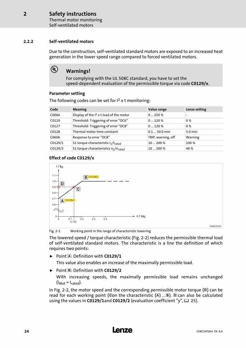
2.2.2 Self−ventilated motors
Due to the construction, self−ventilated standard motors are exposed to an increased heatgeneration in the lower speed range compared to forced ventilated motors.
� Warnings!
For complying with the UL 508C standard, you have to set thespeed−dependent evaluation of the permissible torque via code C0129/x.
Parameter setting
The following codes can be set for I2 x t monitoring:
Code Meaning Value range Lenze setting
C0066 Display of the I2 x t load of the motor 0 ... 250 % −
C0120 Threshold: Triggering of error "OC6" 0 ... 120 % 0 %
C0127 Threshold: Triggering of error "OC8" 0 ... 120 % 0 %
C0128 Thermal motor time constant 0.1 ... 50.0 min 5.0 min
C0606 Response to error "OC8" TRIP, warning, off Warning
C0129/1 S1 torque characteristic I1/Irated 10 ... 200 % 100 %
C0129/2 S1 torque characteristics n2/nrated 10 ... 200 % 40 %
Effect of code C0129/x
0
0.9
0 0.1
C0129/2
0.2 0.3 0.4
0.6
0.7
0.8
1.0
1.1
�
�
0.132
�
I / IN
n / nN
C0129/1
�
9300STD350
Fig. 2−2 Working point in the range of characteristic lowering
The lowered speed / torque characteristic (Fig. 2−2) reduces the permissible thermal loadof self−ventilated standard motors. The characteristic is a line the definition of whichrequires two points:
ƒ Point : Definition with C0129/1
This value also enables an increase of the maximally permissible load.
ƒ Point �: Definition with C0129/2
With increasing speeds, the maximally permissible load remains unchanged(IMot = Irated).
In Fig. 2−2, the motor speed and the corresponding permissible motor torque (�) can beread for each working point (�on the characteristic ( ) ... �). � can also be calculatedusing the values in C0129/1and C0129/2 (evaluation coefficient "y", 25).
Safety instructionsThermal motor monitoring
Self−ventilated motors
2
� 25EDBCSXP064 EN 8.0
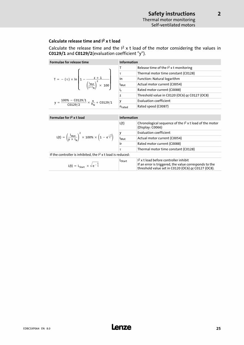
Calculate release time and I2 x t load
Calculate the release time and the I2 x t load of the motor considering the values inC0129/1 and C0129/2(evaluation coefficient "y").
Formulae for release time Information
y �100% � C0129�1
C0129�2� n
nN� C0129�1
T � � (���) � ln����
�1 � z � 1
IMoty�IN2
�� 100
���
�
T Release time of the I2 x t monitoring
� Thermal motor time constant (C0128)
In Function: Natural logarithm
IMot Actual motor current (C0054)
Ir Rated motor current (C0088)
z Threshold value in C0120 (OC6) or C0127 (OC8)
y Evaluation coefficient
nrated Rated speed (C0087)
Formulae for I2 x t load Information
L(t) � IMot
y � IN2
� 100% �1 � e�t�
L(t) Chronological sequence of the I2 x t load of the motor(Display: C0066)
y Evaluation coefficient
IMot Actual motor current (C0054)
Ir Rated motor current (C0088)
� Thermal motor time constant (C0128)
If the controller is inhibited, the I2 x t load is reduced:
L(t) � LStart� � e��t�
� LStart I2 x t load before controller inhibit
If an error is triggered, the value corresponds to thethreshold value set in C0120 (OC6) or C0127 (OC8).

Safety instructionsResidual hazards
2
� 26 EDBCSXP064 EN 8.0
2.3 Residual hazards
Protection of persons
ƒ Before working on the axis module, check that no voltage is applied to the powerterminals, because
– the power terminals +UG, −UG, U, V and W remain live for at least 3 minutes aftermains switch−off.
– the power terminals +UG, −UG, U, V and W remain live when the motor is stopped.
ƒ The heatsink has an operating temperature of > 70 °C:
– Direct skin contact with the heatsink results in burns.
ƒ The discharge current to PE is > 3.5 mA AC or. > 10 mA DC.
– EN 61800−5−1 requires a fixed installation.
– The PE connection must comply with EN 61800−5−1.
– Comply with the further requirements of EN 61800−5−1 for high dischargecurrents!
Device protection
ƒ All pluggable connection terminals must only be connected or disconnected whenno voltage is applied!
ƒ The power terminals +UG, −UG, U, V, W and PE are not protected against polarityreversal.
– When wiring, observe the polarity of the power terminals!
ƒ Power must not be converted until all devices of the power system are ready foroperation. Otherwise, the input current limitation may be destroyed.
Frequent mains switching (e.g. inching mode via mains contactor) can overload anddestroy the input current limitation of the axis module, if
ƒ the axis module is supplied via the ECSxE supply module and the input currentlimitation is activated depending on the DC−bus voltage (C0175 = 1 or 2).
ƒ the axis module is not supplied via a supply module delivered by Lenze.
ƒ the low−voltage supply (24 V) is switched off.
For this reason allow a break of at least three minutes between two starting operations!
Use the safety function ˜Safe torque off˜ (STO) for frequent disconnections for safetyreasons.
Safety instructionsResidual hazards
2
� 27EDBCSXP064 EN 8.0
Motor protection
ƒ Only use motors with a minimum insulation resistance of û = 1.5 kV,min. du/dt = 5 kV/�s.
– Lenze motors meet these requirements.
ƒ When using motors with an unknown insulation resistance, please contact yourmotor supplier.
ƒ Some settings of the axis module lead to an overheating of the connected motor,e.g. longer operation of self−ventilated motors with low speeds.
ƒ Use PTC thermistors or thermostats with PTC characteristic for motor temperaturemonitoring.
Safety instructionsSafety instructions for the installation according to UL
2
� 28 EDBCSXP064 EN 8.0
2.4 Safety instructions for the installation according to UL
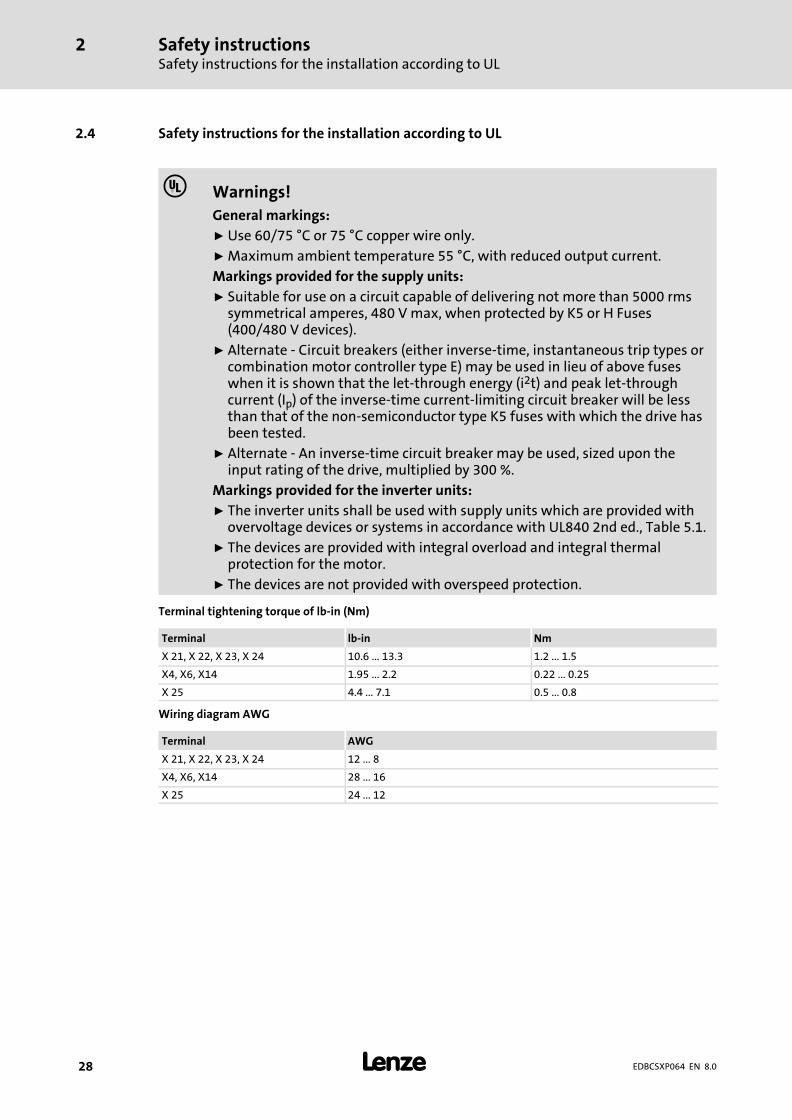
� Warnings!
General markings:
ƒ Use 60/75 °C or 75 °C copper wire only.
ƒ Maximum ambient temperature 55 °C, with reduced output current.
Markings provided for the supply units:
ƒ Suitable for use on a circuit capable of delivering not more than 5000 rmssymmetrical amperes, 480 V max, when protected by K5 or H Fuses(400/480 V devices).
ƒ Alternate − Circuit breakers (either inverse−time, instantaneous trip types orcombination motor controller type E) may be used in lieu of above fuseswhen it is shown that the let−through energy (i2t) and peak let−throughcurrent (Ip) of the inverse−time current−limiting circuit breaker will be lessthan that of the non−semiconductor type K5 fuses with which the drive hasbeen tested.
ƒ Alternate − An inverse−time circuit breaker may be used, sized upon theinput rating of the drive, multiplied by 300 %.
Markings provided for the inverter units:
ƒ The inverter units shall be used with supply units which are provided withovervoltage devices or systems in accordance with UL840 2nd ed., Table 5.1.
ƒ The devices are provided with integral overload and integral thermalprotection for the motor.
ƒ The devices are not provided with overspeed protection.
Terminal tightening torque of lb−in (Nm)
Terminal lb−in Nm
X 21, X 22, X 23, X 24 10.6 ... 13.3 1.2 ... 1.5
X4, X6, X14 1.95 ... 2.2 0.22 ... 0.25
X 25 4.4 ... 7.1 0.5 ... 0.8
Wiring diagram AWG
Terminal AWG
X 21, X 22, X 23, X 24 12 ... 8
X4, X6, X14 28 ... 16
X 25 24 ... 12

Safety instructionsNotes used
2
� 29EDBCSXP064 EN 8.0
2.5 Notes used
The following pictographs and signal words are used in this documentation to indicatedangers and important information:
Safety instructions
Structure of safety instructions:
� Danger!
(characterises the type and severity of danger)
Note
(describes the danger and gives information about how to prevent dangeroussituations)
Pictograph and signal word Meaning
� Danger!
Danger of personal injury through dangerous electrical voltage.Reference to an imminent danger that may result in death orserious personal injury if the corresponding measures are nottaken.
� Danger!
Danger of personal injury through a general source of danger.Reference to an imminent danger that may result in death orserious personal injury if the corresponding measures are nottaken.
� Stop!Danger of property damage.Reference to a possible danger that may result in propertydamage if the corresponding measures are not taken.
Application notes
Pictograph and signal word Meaning
� Note! Important note to ensure troublefree operation
� Tip! Useful tip for simple handling
� Reference to another documentation
Special safety instructions and application notes for UL and UR
Pictograph and signal word Meaning
� Warnings!
Safety or application note for the operation of a UL−approveddevice in UL−approved systems.Possibly the drive system is not operated in compliance with ULif the corresponding measures are not taken.
� Warnings!
Safety or application note for the operation of a UR−approveddevice in UL−approved systems.Possibly the drive system is not operated in compliance with ULif the corresponding measures are not taken.

Technical dataGeneral data and operating conditions
3
� 30 EDBCSXP064 EN 8.0
3 Technical data
3.1 General data and operating conditions
Standards and operating conditions
Conformity CE Low−Voltage Directive (2006/95/EG)
Approvals UL 508C Power Conversion EquipmentUnderwriter Laboratories (File No. E132659)for USA and CanadaCSA 22.2 No. 14
Max. permissibleMotor cable length
shielded 50 m For rated mains voltage and switching frequency of 8 kHz
Packaging (EN ISO 4180) Shipping package
Installation � Installation into IP20 control cabinet� For the "safe torque off" function (formerly "safe standstill"): mounting in IP54
control cabinet
Mounting position vertically suspended
Free space above � 65 mm
below � 65 mmWith ECSZS000X0B shield mounting kit: > 195 mm
to the sides can be mounted directly side by side without any clearance
Environmental conditions
Climate 3k3 in accordance with IEC/EN 60721−3−3Condensation, splash water and ice formationnot permissible.
Storage IEC/EN 60721−3−1 1K3 (−25 ... + 55 °C)
Transport IEC/EN 60721−3−2 2K3 (−25 ... +70 °C)
Operation IEC/EN 60721−3−3 3K3 (0 ... + 55 °C)� Atmospheric pressure: 86 ... 106 kPa� Above +40 °C: reduce the rated output
current by 2 %/°C.
Site altitude 0 ... 4000 m amsl� Reduce rated output current by
5 %/1000 m above 1000 m amsl.� Over 2000 m amsl: Use is only permitted in
environments with overvoltage category II
Pollution EN 61800−5−1, UL840: Degree of pollution 2
Vibration resistance Acceleration resistant up to 0.7 g (Germanischer Lloyd, general conditions)
Technical dataGeneral data and operating conditions
3
� 31EDBCSXP064 EN 8.0
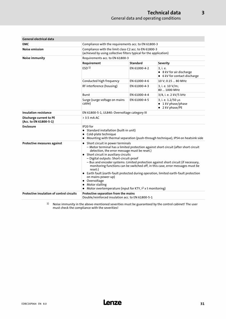
General electrical data
EMC Compliance with the requirements acc. to EN 61800−3
Noise emission Compliance with the limit class C2 acc. to EN 61800−3(achieved by using collective filters typical for the application)
Noise immunity Requirements acc. to EN 61800−3
Requirement Standard Severity
ESD 1) EN 61000−4−2 3, i.� e.� 8 kV for air discharge� 6 kV for contact discharge
Conducted high frequency EN 61000−4−6 10 V; 0.15 ... 80 MHz
RF interference (housing) EN 61000−4−3 3, i.� e. 10 V/m;80 ... 1000 MHz
Burst EN 61000−4−4 3/4, i.� e. 2 kV/5 kHz
Surge (surge voltage on mainscable)
EN 61000−4−5 3, i.� e. 1.2/50 �s� 1 kV phase/phase� 2 kV phase/PE
Insulation resistance EN 61800−5−1, UL840: Overvoltage category III
Discharge current to PE(Acc. to EN 61800−5−1)
> 3.5 mA AC
Enclosure IP20 for� Standard installation (built−in unit)� Cold−plate technique� Mounting with thermal separation (push−through technique), IP54 on heatsink side
Protective measures against � Short circuit in power terminals– Motor terminal has a limited protection against short circuit (after short circuit
detection, the error message must be reset.)� Short circuit in auxiliary circuits
– Digital outputs: Short−circuit−proof– Bus and encoder systems: Limited protection against short circuit (if necessary,
monitoring functions can be switched off, in this case, error messages must bereset:)
� Earth fault (earth−fault protected during operation, limited earth−fault protectionon mains power−up)
� Overvoltage� Motor stalling� Motor overtemperature (input for KTY, I2 x t monitoring)
Protective insulation of control circuits Protective separation from the mainsDouble/reinforced insulation acc. to EN 61800−5−1
1) Noise immunity in the above−mentioned severities must be guaranteed by the control cabinet! The usermust check the compliance with the severities!
Technical dataRated data
3
� 32 EDBCSXP064 EN 8.0
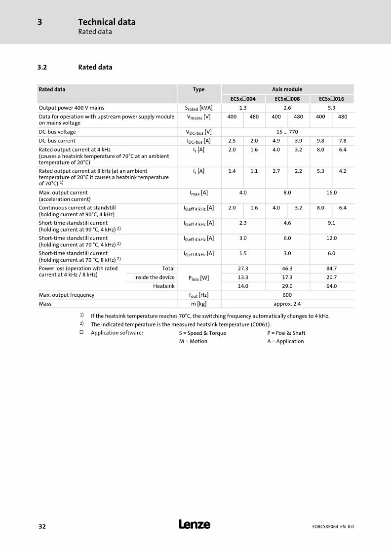
3.2 Rated data
Rated data Type Axis module
ECSx�004 ECSx�008 ECSx�016
Output power 400 V mains Srated [kVA] 1.3 2.6 5.3
Data for operation with upstream power supply moduleon mains voltage
Vmains [V] 400 480 400 480 400 480
DC−bus voltage VDC−bus [V] 15 ... 770
DC−bus current IDC−bus [A] 2.5 2.0 4.9 3.9 9.8 7.8
Rated output current at 4 kHz(causes a heatsink temperature of 70°C at an ambienttemperature of 20°C)
Ir [A] 2.0 1.6 4.0 3.2 8.0 6.4
Rated output current at 8 kHz (at an ambienttemperature of 20°C it causes a heatsink temperatureof 70°C) 1)
Ir [A] 1.4 1.1 2.7 2.2 5.3 4.2
Max. output current(acceleration current)
Imax [A] 4.0 8.0 16.0
Continuous current at standstill(holding current at 90°C, 4 kHz)
I0,eff 4 kHz [A] 2.0 1.6 4.0 3.2 8.0 6.4
Short−time standstill current(holding current at 90 °C, 4 kHz) 2)
I0,eff 4 kHz [A] 2.3 4.6 9.1
Short−time standstill current(holding current at 70 °C, 4 kHz) 2)
I0,eff 4 kHz [A] 3.0 6.0 12.0
Short−time standstill current(holding current at 70 °C, 8 kHz) 2)
I0,eff 8 kHz [A] 1.5 3.0 6.0
Power loss (operation with ratedcurrent at 4 kHz / 8 kHz)
Total
Ploss [W]
27.3 46.3 84.7
Inside the device 13.3 17.3 20.7
Heatsink 14.0 29.0 64.0
Max. output frequency fout [Hz] 600
Mass m [kg] approx. 2.4
1) If the heatsink temperature reaches 70°C, the switching frequency automatically changes to 4 kHz.2) The indicated temperature is the measured heatsink temperature (C0061).
� Application software: S = Speed & Torque P = Posi & Shaft
M = Motion A = Application
Technical dataRated data
3
� 33EDBCSXP064 EN 8.0
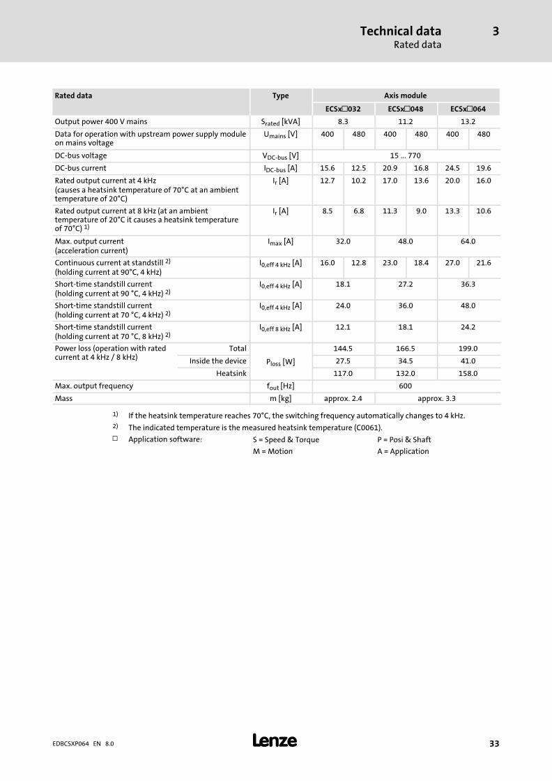
Rated data Type Axis module
ECSx�032 ECSx�048 ECSx�064
Output power 400 V mains Srated [kVA] 8.3 11.2 13.2
Data for operation with upstream power supply moduleon mains voltage
Umains [V] 400 480 400 480 400 480
DC−bus voltage VDC−bus [V] 15 ... 770
DC−bus current IDC−bus [A] 15.6 12.5 20.9 16.8 24.5 19.6
Rated output current at 4 kHz(causes a heatsink temperature of 70°C at an ambienttemperature of 20°C)
Ir [A] 12.7 10.2 17.0 13.6 20.0 16.0
Rated output current at 8 kHz (at an ambienttemperature of 20°C it causes a heatsink temperatureof 70°C) 1)
Ir [A] 8.5 6.8 11.3 9.0 13.3 10.6
Max. output current(acceleration current)
Imax [A] 32.0 48.0 64.0
Continuous current at standstill 2)
(holding current at 90°C, 4 kHz)I0,eff 4 kHz [A] 16.0 12.8 23.0 18.4 27.0 21.6
Short−time standstill current(holding current at 90 °C, 4 kHz) 2)
I0,eff 4 kHz [A] 18.1 27.2 36.3
Short−time standstill current(holding current at 70 °C, 4 kHz) 2)
I0,eff 4 kHz [A] 24.0 36.0 48.0
Short−time standstill current(holding current at 70 °C, 8 kHz) 2)
I0,eff 8 kHz [A] 12.1 18.1 24.2
Power loss (operation with ratedcurrent at 4 kHz / 8 kHz)
Total
Ploss [W]
144.5 166.5 199.0
Inside the device 27.5 34.5 41.0
Heatsink 117.0 132.0 158.0
Max. output frequency fout [Hz] 600
Mass m [kg] approx. 2.4 approx. 3.3
1) If the heatsink temperature reaches 70°C, the switching frequency automatically changes to 4 kHz.2) The indicated temperature is the measured heatsink temperature (C0061).
� Application software: S = Speed & Torque P = Posi & Shaft
M = Motion A = Application

Technical dataCurrent characteristicsIncreased continuous current depending on the control factor
3
� 34 EDBCSXP064 EN 8.0
3.3 Current characteristics
3.3.1 Increased continuous current depending on the control factor
In the lower speed range ˘ the motor does not need the full motor voltage ˘ particularlythe more powerful ECS axis modules can be permanently operated with increased outputcurrent (cp. continuous current I0,eff � 32).
27.0
23.0
16.0
8.0
4.0
0.0
5.0
10.0
15.0
20.0
25.0
20.0
17.0
12.7
8.0
4.0
30.0
0 % 50 % 100 %
ECSxS/P/M/A048
ECSxS/P/M/A032
ECSxS/P/M/A016
ECSxS/P/M/A008
ECSxS/P/M/A004 2.02.0
I [A]
U / UMot max
ECSxS/P/M/A064
I [A]0
I [A]N
ECSXA002
Fig. 3−1 Continuous device current, depending on the output voltage for Umains � 400 V at 4 kHz
Ir Rated output current of the axis moduleUMot_n Actual controller output voltageUMot_max 0.9 x current mains voltage
The permissible continuous current depends on the control factor of the power outputstages, approximately on the ratio of the motor voltage output in the operating point(UMot_n) to the maximum possible output voltage (UMot_max). Due to voltage drops acrossthe components involved at rated load and a control margin, UMot_max can be estimatedwith 90 % of the mains voltage.
� Tip!
The operating threshold of the device utilisation monitoring (I x t) function isautomatically adapted to the continuous device current which changesdepending on the output voltage (see fig.).
Technical dataCurrent characteristics
Increased continuous current depending on the control factor
3
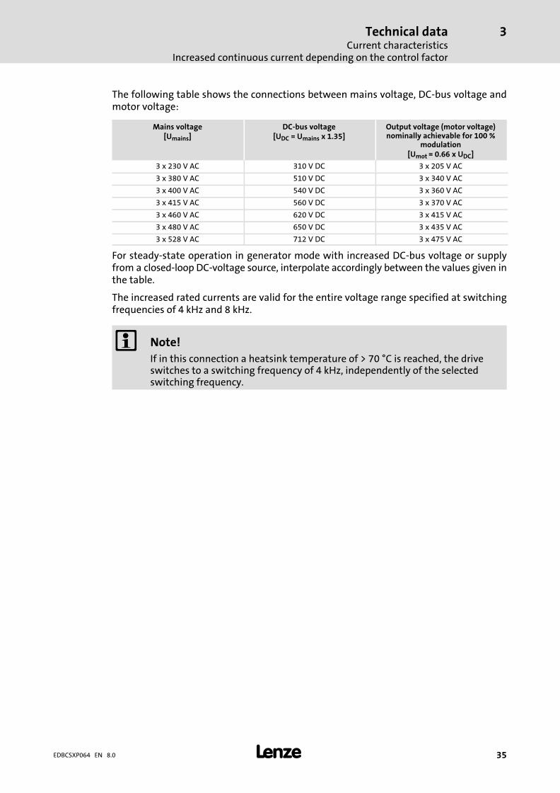
� 35EDBCSXP064 EN 8.0
The following table shows the connections between mains voltage, DC−bus voltage andmotor voltage:
Mains voltage[Umains]
DC−bus voltage[UDC = Umains x 1.35]
Output voltage (motor voltage)nominally achievable for 100 %
modulation[Umot = 0.66 x UDC]
3 x 230 V AC 310 V DC 3 x 205 V AC
3 x 380 V AC 510 V DC 3 x 340 V AC
3 x 400 V AC 540 V DC 3 x 360 V AC
3 x 415 V AC 560 V DC 3 x 370 V AC
3 x 460 V AC 620 V DC 3 x 415 V AC
3 x 480 V AC 650 V DC 3 x 435 V AC
3 x 528 V AC 712 V DC 3 x 475 V AC
For steady−state operation in generator mode with increased DC−bus voltage or supplyfrom a closed−loop DC−voltage source, interpolate accordingly between the values given inthe table.
The increased rated currents are valid for the entire voltage range specified at switchingfrequencies of 4 kHz and 8 kHz.
� Note!
If in this connection a heatsink temperature of > 70 °C is reached, the driveswitches to a switching frequency of 4 kHz, independently of the selectedswitching frequency.

Technical dataCurrent characteristicsIncreased continuous current depending on the control factor
3
� 36 EDBCSXP064 EN 8.0
Example:
The ECS axis module suitable for operation in conjunction with a Lenze motor of typeMCS 14L32 is to be determined.
ƒ Rated motor data
– Rated motor torque (Mmot) = 17.2 Nm
– Rated motor speed (nmot) = 3225 rpm
– Motor voltage at 3250 rpm (Umot_n3250) = 275 V
– Rated motor current (Imot) = 15 A
– Max. motor current (Imot_max) = 92 A
ƒ Application data:
– Max. torque (Mmax) = 35 Nm
– Max. operating speed (nmax) = 2500 rpm
– An effective process power (Peff) of 4.5 kW arises on the basis of the Mn diagram.
– The drive rating results in an effective motor current (IMot_eff) of 14.8 A.
A first estimation based on the rated current of the ECS axis module would probably leadto selecting the ECSxP048 module with a rated current of 17.0 A.
However, if we take into account the increased continuous current for smaller controlfactors, the more cost−effective ECSxP032 axis module with a rated current of 12.7 A canbe used here.
ƒ When the MCS 14L32 is operated with 2500 rpm, the real motor voltage is(UMot_n2500):
UMot_n2500 � UMot_n3250 �nmaxnMot
� 275�V� �2500�rpm3250�rpm
� 212�V
ƒ This leads to the following max. control factor (αmax) of the axis module:
�max �UMot_n2500
Umax
� 212�V360�V
� 0.59 � 59�%
Using the current characteristic of Fig. 3−1 (� 34), a continuous current of 15.5 A canbe determined for the ECSxP032 axis module when the control factor (αmax) is 59 %.
ƒ Result:
Under the conditions mentioned above the MCS 14L32 Lenze motor can be operatedcontinuously on the ECSxP032 axis module.

Technical dataCurrent characteristics
Device protection by current derating
3
� 37EDBCSXP064 EN 8.0
3.3.2 Device protection by current derating
The maximum output current is limited. With output frequencies < 5 Hz the limitationdepends on the heatsink temperature.
0.75
1.00
0.57
0.38
0.67
0.00
1.00
0 5 10fout [Hz]
IoutImax
≤ 70 °C
90 °C
��
�
ECSXA024
Fig. 3−2 Current derating characteristics
� Operation with switching frequency = 8 kHz (C0018 = 1).� If the current exceeds the characteristic �, the switching frequency is automatically
changed to 4 kHz (e.g. for higher torque in acceleration processes).� Operation with switching frequency = 4 kHz (C0018 = 0).
� The current limitation follows the characteristic �.� With output frequencies < 5 Hz and heatsink temperatures between 70 and 90 °C the
current limit is steplessly adjusted in the range �.
Type Imax [A]
Switching frequency 8 kHz � Switching frequency 4 kHz �
fout > 5 Hz fout � 0 Hz fout > 5 Hz fout � 0 Hz� 70 °C
fout � 0 Hz90 °C
ECSxP004 2.7 1.5 4.0 3.0 2.3
ECSxP008 5.3 3.0 8.0 6.0 4.6
ECSxP016 10.7 6.0 16.0 12.0 9.1
ECSxP032 21.3 12.1 32.0 24.0 18.1
ECSxP048 32.0 18.1 48.0 36.3 27.2
ECSxP064 42.7 24.2 64.0 48.0 36.3
Mechanical installationImportant notes
4
� 38 EDBCSXP064 EN 8.0
4 Mechanical installation
4.1 Important notes
ƒ Axis modules of the ECS series provide IP20 enclosure and can therefore only beused for installation in control cabinets.
ƒ If the cooling air contains air pollutants (dust, fluff, grease, aggressive gases):
– Take suitable preventive measures , e.g. separate air duct, installation of filters,regular cleaning.
ƒ Possible mounting positions:
– Vertical at the mounting plate
– DC bus connections (X23) at the top
– Motor connection (X24) at the bottom
ƒ Maintain the specified clearances (above and below) to other installations!
– If the ECSZS000X0B shield mounting kit is used, an additional clearance isrequired.
– Ensure unimpeded ventilation of cooling air and outlet of exhaust air.
– Several modules of the ECS series can be installed in the control cabinet next toeach other without any clearance.
ƒ The mounting plate of the control cabinet
– must be electrically conductive.
– must not be varnished.
ƒ In case of continuous vibrations or shocks use shock absorbers.
Mechanical installationMounting with fixing rails (standard installation)
Dimensions
4
� 39EDBCSXP064 EN 8.0
4.2 Mounting with fixing rails (standard installation)
4.2.1 Dimensions
� Note!
Mounting with ECSZS000X0B shield mounting kit:
ƒ Mounting clearance below the module > 195 mm
h h
a
gg
a
d1d
g g
� �
�6
5m
m
e�6
5m
m
d1db b
ECSxA005
Fig. 4−1 Dimensions for "panel−mounted" design
Axis module Dimensions [mm]
Type Size a b d d1 e h g
ECSE�004
88,5
240 276 260176
212 1) 106,5
(M6)
ECSE�008
ECSE�016
ECSE�032
ECSE�048� 131
ECSE�064
1) Max. 212 mm, depending on the plugged−on communication module
� Application software: S = Speed & Torque P = Posi & Shaft
M = Motion A = Application

Mechanical installationMounting with fixing rails (standard installation)Mounting steps
4
� 40 EDBCSXP064 EN 8.0
4.2.2 Mounting steps
How to install the axis module:
1. Prepare the fixing holes on the mounting surface.
– Use the drilling jig for this purpose.
2. Take the fixing rails from the accessory kit in the cardboard box.
3. Push the rails into the slots of the heatsink:
– From above: Push in the long side.
– From below: Push in the short side.
4. Attach the axis module to the mounting surface.
Mechanical installationMounting with thermal separation (push−through technique)
4
� 41EDBCSXP064 EN 8.0
4.3 Mounting with thermal separation (push−through technique)
For the push−through technique the rear panel of the control cabinet must be a steel platewith a thickness of at least 2 mm.
The edges of the mounting cutout and the fixing holes for the clamps must be slightlycurved inwards (towards the axis module).
Cooling
With the separated heatsink the heat generation in the control cabinet can be reduced.
ƒ Distribution of the power loss:
– approx. 65 % via separated cooler
– approx. 35 % in the inside of the axis module
ƒ Protection class of the separated cooler: IP54
– The sealing surface at the heatsink of the axis module must rest completelyagainst the mounting plate.
– Use a liquid thread sealant to bond the screws of the clamps.
ƒ For sufficient cooling of the drive system:
– Air flow behind the rear panel of the control cabinet must be � 3 m/s (e.g. by meansof a collective fan).
ƒ With sufficient cooling, the rated data of the axis modules remain valid.
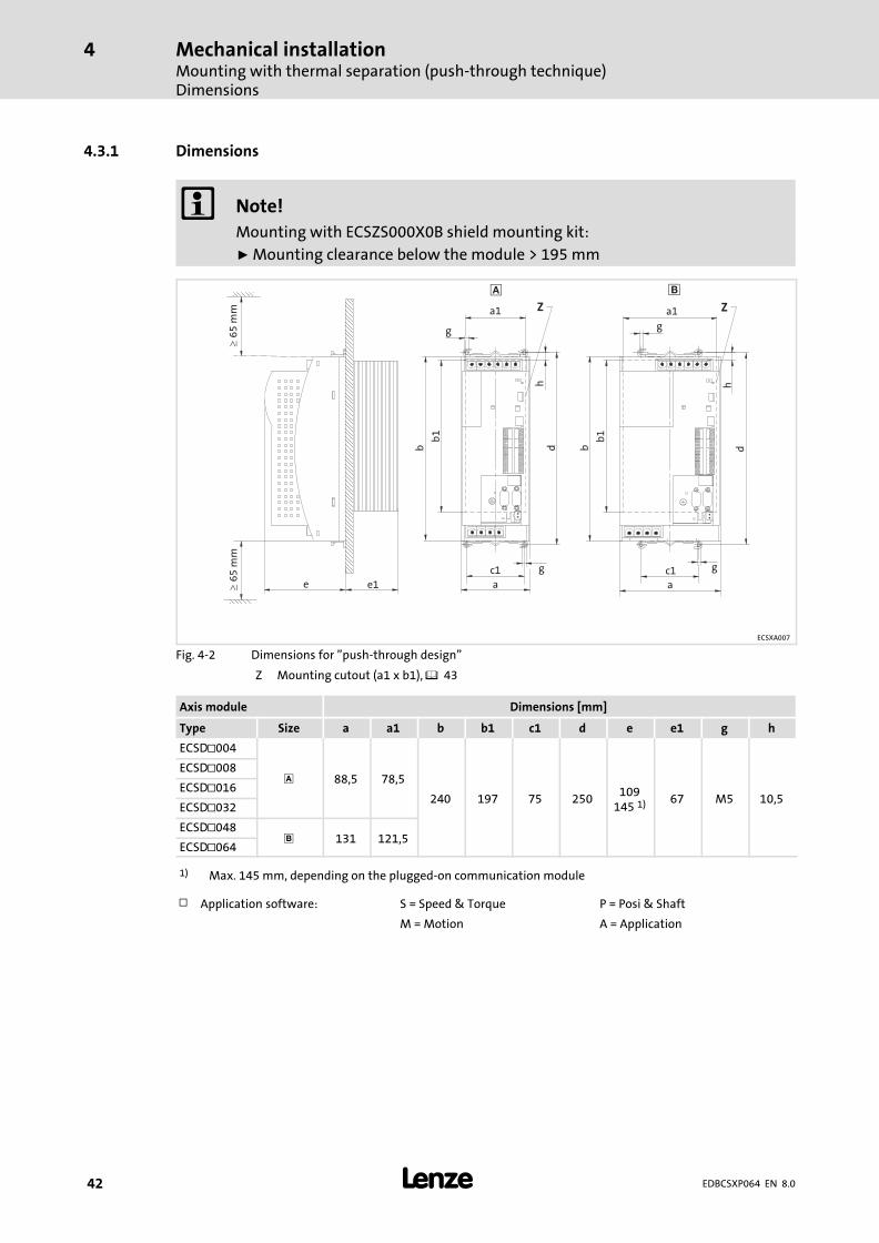
Mechanical installationMounting with thermal separation (push−through technique)Dimensions
4
� 42 EDBCSXP064 EN 8.0
4.3.1 Dimensions
� Note!
Mounting with ECSZS000X0B shield mounting kit:
ƒ Mounting clearance below the module > 195 mm
Z
c1 c1
h h
a1
e e1 a
g
gg
db
g
a
db
b1
b1
�6
5m
m�
65
mm a1 Z
� �
ECSXA007
Fig. 4−2 Dimensions for "push−through design"
Z Mounting cutout (a1 x b1), � 43
Axis module Dimensions [mm]
Type Size a a1 b b1 c1 d e e1 g h
ECSD�004
88,5 78,5
240 197 75 250109
145 1) 67 M5 10,5
ECSD�008
ECSD�016
ECSD�032
ECSD�048� 131 121,5
ECSD�064
1) Max. 145 mm, depending on the plugged−on communication module
� Application software: S = Speed & Torque P = Posi & Shaft
M = Motion A = Application

Mechanical installationMounting with thermal separation (push−through technique)
Dimensions
4
� 43EDBCSXP064 EN 8.0
Dimensions of mounting cutout
� Note!
Installation with shield mounting ECSZS000X0B:
ƒ Clearance below the mounting cutout > 220 mm�
70
mm
�9
0m
m
a1 a1
��
c1
h
c1
gg
b1
b1
d
�ECSXA063
Fig. 4−3 Dimensions of mounting cutout
Mounting surface� Mounting cutout for size � Mounting cutout for size �
Axis module Dimensions [mm]
Type Size a1 b1 c1 d g h
ECSD�004
78,5
197 75 250 M5 10,5
ECSD�008
ECSD�016
ECSD�032
ECSD�048� 121,5
ECSD�064
� Application software: S = Speed & Torque P = Posi & Shaft
M = Motion A = Application

Mechanical installationMounting with thermal separation (push−through technique)Mounting steps
4
� 44 EDBCSXP064 EN 8.0
4.3.2 Mounting steps
How to mount the axis module:
1. Prepare the fixing holes for the wire clamps on the mounting area.
For this purpose, apply a drilling jig.
2. Prepare the mounting cutout.
The edges of the mounting cutout and the fixing holes for the wire clamps have to beslightly arched inwardly (to the axis module).
3. Apply liquid thread sealant to the threads of the screws for the wire clamps.
4. Fix the wire clamps together with the functional earth conductor supplied (Fig. 4−4).
The functional earth conductor is part of the scope of supply of the ECSDx... axis module
5. Push the axis module into the mounting cutout.
6. Engage axis module in the wire clamp at the top and the bottom.
7. Connect the functional earth conductor to the axis module (Fig. 4−4).
� Note!
Fixing the functional earth conductor to the ECSDx... axis module is requiredfor a better electromagnetic compatibility (EMC).
ECSXA081
Fig. 4−4 Functional earth conductor at the ECSDx... axis module
Functional earth conductor
Mechanical installationMounting in cold−plate design
4
� 45EDBCSXP064 EN 8.0
4.4 Mounting in cold−plate design
The axis modules ECSC... are intended for mounting in cold−plate design (e.g. on collectivecoolers).
Requirements for collective coolers
The following requirements must be met to ensure a safe operation of the axis modules:
ƒ Good thermal contact with the cooler
– The contact surface between collective cooler and axis module must be at least aslarge as the cooling plate of the axis module.
– Smooth contact surface, max. deviation 0.05 mm.
– Connect the collective cooler with all specified screwed connections to the axismodule.
ƒ Maintain the thermal resistance Rth according to the table.
– The values apply for operating the axis modules under rated conditions.
Axis module Power to be dissipated Heat sink − environment
Type Ploss [W] Rth [k/W]
ECSC�004 14.0
0,31ECSC�008 29.0
ECSC�016 64.0
ECSC�032 117.00,13
ECSC�048 132.0
ECSC�064 158.0 0,11
� Application software: S = Speed & Torque P = Posi & Shaft
M = Motion A = Application
ƒ Ambient conditions:
– Furthermore the rated data regarding the ambient temperature and the deratingfactors at increased temperature apply to the axis modules (� 30 et seqq.).
– Temperature of the cooling plate ("Cold Plate"): max. +85 °C

Mechanical installationMounting in cold−plate designDimensions
4
� 46 EDBCSXP064 EN 8.0
4.4.1 Dimensions
� Note!
Mounting with ECSZS000X0B shield mounting kit:
ƒ Mounting clearance below the module > 195 mm
c1 c1
a1 a1
e
g
gg
b
g
a
d
b
a� �
�6
5m
m�
65
mm
ECSXA009
Fig. 4−5 Dimensions for "cold−plate design"
Axis module Dimensions [mm]
Type Size a a1 b c1 d e g
ECSC�004
88,5 60
282 50 287121
157 1) M6
ECSC�008
ECSC�016
ECSC�032
ECSC�048� 131 90
ECSC�064
1) Max. 157 mm, depending on the plugged−on communication module
� Application software: S = Speed & Torque P = Posi & Shaft
M = Motion A = Application
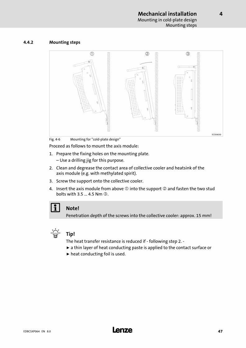
Mechanical installationMounting in cold−plate design
Mounting steps
4
� 47EDBCSXP064 EN 8.0
4.4.2 Mounting steps
� � �
ECSXA030
Fig. 4−6 Mounting for "cold−plate design"
Proceed as follows to mount the axis module:
1. Prepare the fixing holes on the mounting plate.
– Use a drilling jig for this purpose.
2. Clean and degrease the contact area of collective cooler and heatsink of theaxis module (e.g. with methylated spirit).
3. Screw the support onto the collective cooler.
4. Insert the axis module from above � into the support � and fasten the two studbolts with 3.5 ... 4.5 Nm �.
� Note!
Penetration depth of the screws into the collective cooler: approx. 15 mm!
� Tip!
The heat transfer resistance is reduced if − following step 2. −
ƒ a thin layer of heat conducting paste is applied to the contact surface or
ƒ heat conducting foil is used.
Electrical installationInstallation according to EMC (installation of a CE−typical drive system)
5
� 48 EDBCSXP064 EN 8.0
5 Electrical installation
5.1 Installation according to EMC (installation of a CE−typical drive system)
General information
ƒ The electromagnetic compatibility of a machine depends on the type of installationand care taken.Especially consider the following:
– Assembly
– Filtering
– Shielding
– Earthing
ƒ For diverging installations, the evaluation of the conformity to the EMC Directiverequires a check of the machine or system regarding the EMC limit values. This forinstance applies to:
– Use of unshielded cables
– Use of collective interference filters instead of the assigned RFI filters
– Operating without RFI filters
ƒ The compliance of the machine application with the EMC Directive is in theresponsibility of the user.
– If you observe the following measures, you can assume that the machine willoperate without any EMC problems caused by the drive system, and thatcompliance with the EMC Directive and the EMC law is achieved.
– If devices which do not comply with the CE requirement concerning noiseimmunity EN 61000−6−2 are operated close to the ECS modules, these devices maybe electromagnetically affected by the ECS modules.
Electrical installationInstallation according to EMC (installation of a CE−typical drive system)
5
� 49EDBCSXP064 EN 8.0
Assembly
ƒ Connect the ECS modules, RFI filters, and mains choke to the earthed mountingplate with a surface as large as possible:
– Mounting plates with conductive surfaces (zinc−coated or stainless steel) allow forpermanent contact.
– Painted plates are not suitable for an EMC−compliant installation.
ƒ If you use the ECSxK... capacitor module:
– Install the capacitor module between the power supply module and the axismodule(s).
– If the total cable length in the DC−bus connection is > 5 m, install the capacitormodule as close as possible to the axis module with the greatest power.
ƒ If you use several mounting plates:
– Connect as much surface of the mounting plates as possible (e.g. with copperbands).
ƒ Ensure the separation of the motor cable and the signal or mains cables.
ƒ Avoid a common terminal/power strip for the mains input and motor output.
ƒ Lay the cables as close as possible to the reference potential. Freely suspendedcables act like aerials.
Filters
Only use RFI filters and mains chokes which are assigned to the power supply modules:
ƒ RFI filters reduce impermissible high−frequency interferences to a permissible value.
ƒ Mains chokes reduce low−frequency interferences which in particular depend on themotor cables and their lengths.
Electrical installationInstallation according to EMC (installation of a CE−typical drive system)
5
� 50 EDBCSXP064 EN 8.0
Shielding
ƒ Connect the motor cable shield to the axis module
– with the ECSZS000X0B shield mounting kit.
– extensively to the mounting plate below the axis module.
– Recommendation: For the shield connection, use earthing clamps on bare metalmounting surfaces.
ƒ If contactors, motor protection switches or terminals are located in the motor cable:
– Connect the shields of the connected cables to each other and connect them to themounting plate, too, with a surface as large as possible.
ƒ Connect the shield in the motor terminal box or on the motor housing extensively toPE:
– Metal glands at the motor terminal box ensure an extensive connection of theshield and the motor housing.
ƒ Shield UG cables and control cables from a length of 0.3 m:
– Connect both shields of the digital control cables.
– Connect one shield end of the analog control cables.
– Always connect the shields to the shield connection at the axis module over theshortest possible distance.
ƒ Use of the ECS modules in residential areas:
– Additionally dampen the shield in order to limit the interfering radiation: �10 dB .This can be achieved by using standard, closed, metallic, and earthed controlcabinets or boxes.
Earthing
ƒ Earth all metallically conductive components (e.g. ECS modules, RFI filters, motorfilters, mains chokes) using suitable cables connected to a central earthing point (PErail).
ƒ Maintain the minimum cross−sections prescribed in the safety regulations:
– For EMC not the cable cross−section is important, but the surface of the cable andthe contact with a cross−section as large as possible, i.e. large surface.
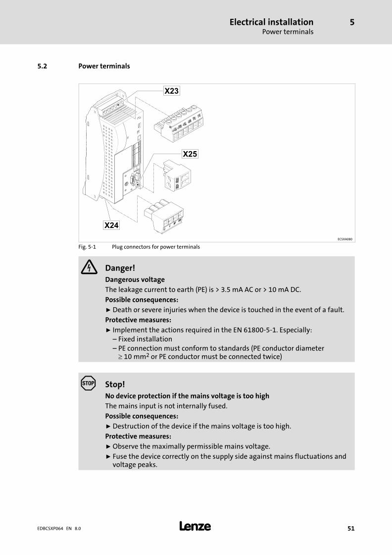
Electrical installationPower terminals
5
� 51EDBCSXP064 EN 8.0
5.2 Power terminals
ECSXA080
Fig. 5−1 Plug connectors for power terminals
� Danger!
Dangerous voltage
The leakage current to earth (PE) is > 3.5 mA AC or > 10 mA DC.
Possible consequences:
ƒ Death or severe injuries when the device is touched in the event of a fault.
Protective measures:
ƒ Implement the actions required in the EN 61800−5−1. Especially:– Fixed installation– PE connection must conform to standards (PE conductor diameter� 10 mm2 or PE conductor must be connected twice)
� Stop!
No device protection if the mains voltage is too high
The mains input is not internally fused.
Possible consequences:
ƒ Destruction of the device if the mains voltage is too high.
Protective measures:
ƒ Observe the maximally permissible mains voltage.
ƒ Fuse the device correctly on the supply side against mains fluctuations andvoltage peaks.
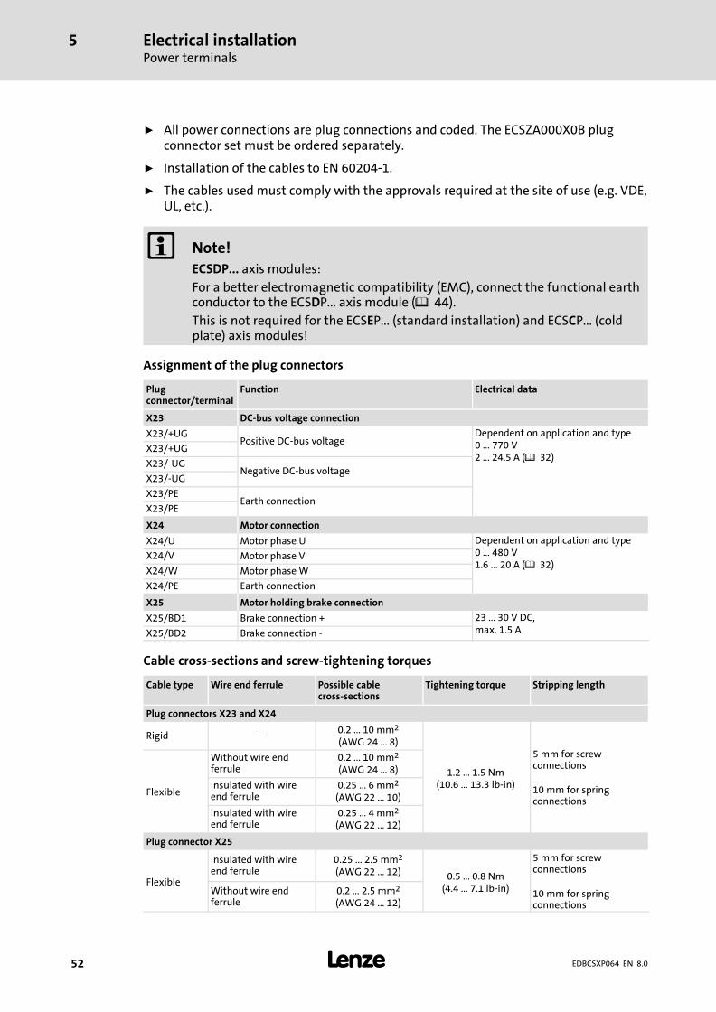
Electrical installationPower terminals
5
� 52 EDBCSXP064 EN 8.0
ƒ All power connections are plug connections and coded. The ECSZA000X0B plugconnector set must be ordered separately.
ƒ Installation of the cables to EN 60204−1.
ƒ The cables used must comply with the approvals required at the site of use (e.g. VDE,UL, etc.).
� Note!
ECSDP... axis modules:
For a better electromagnetic compatibility (EMC), connect the functional earthconductor to the ECSDP... axis module (� 44).
This is not required for the ECSEP... (standard installation) and ECSCP... (coldplate) axis modules!
Assignment of the plug connectors
Plugconnector/terminal
Function Electrical data
X23 DC−bus voltage connection
X23/+UGPositive DC−bus voltage
Dependent on application and type0 ... 770 V2 ... 24.5 A (� 32)
X23/+UG
X23/−UGNegative DC−bus voltage
X23/−UG
X23/PEEarth connection
X23/PE
X24 Motor connection
X24/U Motor phase U Dependent on application and type0 ... 480 V1.6 ... 20 A (� 32)
X24/V Motor phase V
X24/W Motor phase W
X24/PE Earth connection
X25 Motor holding brake connection
X25/BD1 Brake connection + 23 ... 30 V DC,max. 1.5 AX25/BD2 Brake connection −
Cable cross−sections and screw−tightening torques
Cable type Wire end ferrule Possible cablecross−sections
Tightening torque Stripping length
Plug connectors X23 and X24
Rigid ˘0.2 ... 10 mm2
(AWG 24 ... 8)
1.2 ... 1.5 Nm(10.6 ... 13.3 lb−in)
5 mm for screwconnections
10 mm for springconnections
Flexible
Without wire endferrule
0.2 ... 10 mm2
(AWG 24 ... 8)
Insulated with wireend ferrule
0.25 ... 6 mm2
(AWG 22 ... 10)
Insulated with wireend ferrule
0.25 ... 4 mm2
(AWG 22 ... 12)
Plug connector X25
Flexible
Insulated with wireend ferrule
0.25 ... 2.5 mm2
(AWG 22 ... 12) 0.5 ... 0.8 Nm(4.4 ... 7.1 lb−in)
5 mm for screwconnections
10 mm for springconnections
Without wire endferrule
0.2 ... 2.5 mm2
(AWG 24 ... 12)
Electrical installationPower terminals
5
� 53EDBCSXP064 EN 8.0
Shielded cables
The following factors decisively determine the effect of the shielded cables:
ƒ Good shield connection
– Ensure a contact surface as large as possible
ƒ Low shield resistance
– Only use shields with tin−plated or nickel−plated copper braids (shields with steelbraids cannot be used).
ƒ High overlap rate of the braid
– At least 70 ... 80 % with 90° overlap angle
The ECSZS000X0B shield mounting kit includes a wire clamp and shield sheet.

Electrical installationPower terminalsConnection to the DC bus (+UG, −UG)
5
� 54 EDBCSXP064 EN 8.0
5.2.1 Connection to the DC bus (+UG, −UG)
� Stop!
No device protection for DC bus voltage surges
In passive axis modules (without 24 V−supply), the charging circuit can beoverloaded through DC bus voltage surges.
Possible consequences:
ƒ Destruction of the device
Protective measures:
ƒ All axis modules in the DC−bus connection should be basically supplied witha control voltage of 24 V.
ƒ If the total cable length is > 20 m, install an axis module or a capacitor moduledirectly at the power supply module.
ƒ Design the ±UG cables twisted and as short as possible. Ensure short−circuit−proofrouting!
ƒ Cable length (module module) > 30 cm: install shielded ±UG cables.
Cable cross−section
Cable length(module/module)
Wire end ferrule Cable cross−section Tightening torque Stripping length
Up to 20 m
Without wire endferrule 6 mm2
(AWG 10)
1.2 ... 1.5 Nm(10.6 ... 13.3 lb−in)
5 mm for screwconnection
10 mm for springconnection
With insulated wire endferrule
> 20 m
Without wire endferrule
10 mm2
(AWG 8)With insulated wire endferruleUse pin−end connectorsfor wiring!

Electrical installationPower terminals
Connection to the DC bus (+UG, −UG)
5
� 55EDBCSXP064 EN 8.0
Fuses
ƒ Mains fuses are not included in the Lenze delivery program. Use standard fuses.
ƒ When using ECSxE power supply modules which are fused on the supply side theDC−bus supply need not be fused.
ƒ When ECS axis modules are supplied by devices of the 82xx and 93xx series with acontinuous DC current > 40 A, install the following fuses between the supplyingdevice and the ECS devices:
Fuse Support
Value [A] Lenze type Lenze type
50 EFSGR0500ANIN EFH20007
ƒ Observe the national and regional regulations (VDE, UL, EVU, ...).
� Warnings!
ƒ Use UL−approved cables, fuses and fuse holders only.
ƒ UL fuse:– Voltage 500 ... 600 V– Tripping characteristic "H", "K5" or "CC"
Replacing defective fuses
� Danger!
Hazardous electrical voltage
Components can carry hazardous voltages up to 3 minutes after power−off.
Possible consequences:
ƒ Death or severe injuries when touching the device.
Protective measures:
ƒ Replace fuses in the deenergised state only.– Set controller inhibit (CINH) for all axis modules in DC−bus operation and
disconnect all power supply modules from the mains.
Electrical installationPower terminalsConnection plan for mimimum wiring with internal brake resistor
5
� 56 EDBCSXP064 EN 8.0
5.2.2 Connection plan for mimimum wiring with internal brake resistor
� Documentation of the ECSxE power supply module
Observe the enclosed notes.
� Stop!
Always operate the ECS power supply modules with a brake resistor(internal/external).
The ECS power supply modules in the standard built−in unit and push−through design(ECSEE / ECSDE) are provided with a device−internal brake resistor.
In order to use the internal brake resistor (Rb), carry out the following wiring:
ƒ Bridge between the terminals X22/+UG and X22/BR0 (CR)
Current flow from +UG via the internal brake resistor (Rb) and the brake transistor to−UG.
ƒ Bridge between the terminals X6/T1 and X6/T2 (CR)
Deactivate the temperature monitoring of the non−existing external brake resistor.

Electrical installationPower terminals
Connection plan for mimimum wiring with internal brake resistor
5
� 57EDBCSXP064 EN 8.0
L3
N
L1L2
Z1
K1
K1
L1 L2 L3 PE
X21
+UG +UG +UG-UG -UG-UGPE PEPE
X22 X23
Off
On+UGBR1BR0
M3~ R
T1 T2
X6
...
�2
6
K1
�
Rb
U V W PE
X24
BD1 BD2
X25 X7
�
�
�
�
�
+UG +UG -UG-UG PEPE
X23
M3~ R
�2
6
�
U V W PE
X24
BD1 BD2
X25 X7
�
�
�
�
�
F4F1...F3
�
�
ECSxS/P/M/A...ECSEE...
ECSDE...
ECSxS/P/M/A...
ECSXA011
Fig. 5−2 Interconnected power system with internal brake resistor
� HF−shield termination by large surface connection to functional earth (see mountinginstructions for shield mounting ECSZS000X0B)
Twisted cables
K1 Mains contactorF1 ... F4 FuseZ1 Mains choke / mains filter, optionalRb Internal brake resistor KTY thermal sensor of the motor System cable for feedback

Electrical installationPower terminalsConnection plan for mimimum wiring with external brake resistor
5
� 58 EDBCSXP064 EN 8.0
5.2.3 Connection plan for mimimum wiring with external brake resistor
� Documentation of the ECSxE power supply module
Observe the enclosed notes.
� Stop!
ƒ Always operate the ECS power supply modules with a brake resistor.
ƒ A parallel wiring of internal and external brake resistor is not permissible!
ƒ Implement the thermal contact of the brake resistor into the systemmonitoring so that the mains supply of the power supply module will beswitched off in case the brake resistor will be overheated.
ƒ Read the documentation for the external brake resistor. Observe the safetyinstructions contained therein.
If the power supply module needs a high amount of braking power when it comes asstandard built−in unit or in push−through technique design (ECSEE / ECSDE), an externaland more powerful brake resistor can be connected instead of the internal brake resistor.
A power supply module in cold plate technique design (ECSCE) is not provided with aninternal brake resistor so that this version always requires an external brake resistor(Rbext).
ƒ Connect the brake resistor to X22/BR1 and X22/+UG.
ƒ Connect the thermal contact (NC contact) of the external brake resistor to X6/T1and X6/T2.

Electrical installationPower terminals
Connection plan for mimimum wiring with external brake resistor
5
� 59EDBCSXP064 EN 8.0
F4
K1
K1
Off
On
L3
N
L1L2
K1
F1...F3
Z1
L1 L2 L3 PE
X21
+UG +UG +UG-UG -UG-UGPE PEPE
X22 X23
+UGBR1BR0
M3~ R
T1 T2
X6
...
�2
6
�
U V W PE
X24
BD1 BD2
X25 X7
�
�
�
�
�
+UG +UG -UG-UG PEPE
X23
M3~ R
�2
6
�
U V W PE
X24
BD1 BD2
X25 X7
�
�
�
�
�
ECSxS/P/M/A...ECSxE... ECSxS/P/M/A...
�
�
Rbext
�
�
(Rbext)
ECSXA012
Fig. 5−3 Interconnected power system with external brake resistor
� HF−shield termination by large surface connection to functional earth (see mountinginstructions for shield mounting ECSZS000X0B)
Twisted cables
K1 Mains contactorF1 ... F4 FuseZ1 Mains choke / mains filter, optionalRbext External brake resistor KTY thermal sensor of the motor System cable for feedback
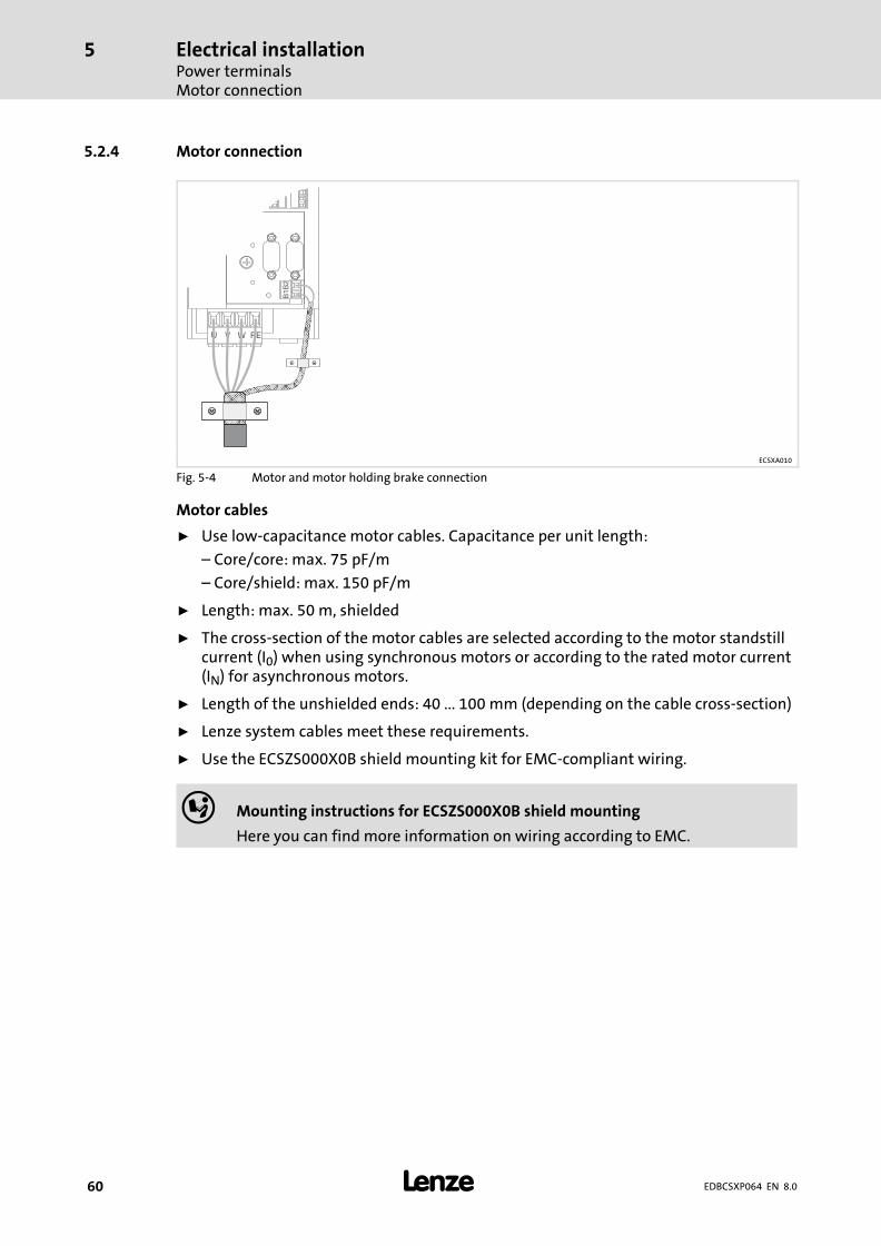
Electrical installationPower terminalsMotor connection
5
� 60 EDBCSXP064 EN 8.0
5.2.4 Motor connection
ECSXA010
Fig. 5−4 Motor and motor holding brake connection
Motor cables
ƒ Use low−capacitance motor cables. Capacitance per unit length:
– Core/core: max. 75 pF/m
– Core/shield: max. 150 pF/m
ƒ Length: max. 50 m, shielded
ƒ The cross−section of the motor cables are selected according to the motor standstillcurrent (I0) when using synchronous motors or according to the rated motor current(IN) for asynchronous motors.
ƒ Length of the unshielded ends: 40 ... 100 mm (depending on the cable cross−section)
ƒ Lenze system cables meet these requirements.
ƒ Use the ECSZS000X0B shield mounting kit for EMC−compliant wiring.
� Mounting instructions for ECSZS000X0B shield mounting
Here you can find more information on wiring according to EMC.

Electrical installationPower terminals
Motor holding brake connection
5
� 61EDBCSXP064 EN 8.0
5.2.5 Motor holding brake connection
The motor holding brake
ƒ is connected to X25/BD1 and X25/BD2.
ƒ is supplied with low voltage via the terminals X6/B+ and X6/B−:
+23 ... +30 V DC, max.1.5 A
� Stop!
ƒ Protect X6/B+ with an F 1.6 A fuse.
ƒ If no suitable voltage (incorrect amount, incorrect polarity) is connected tothe brake, it is applied and can overheat or be destroyed by the continuouslyrunning motor.
5.2.5.1 Spark suppressor
The axis module comes with an integrated spark suppressor for protecting the contacts ofthe integrated brake relay when the motor holding brake (inductive load) is switched.
5.2.5.2 Monitoring the brake connection
The connection of the motor holding brake can be monitored for voltage failure and cablebreakage if monitoring is activated under C0602.
The monitoring system of the brake connection trips under the following conditions:
Case 1, motor holding brake released (brake relay contact is closed):
ƒ Current via holding brake (IB) < 140 mA +/−10 % or
ƒ Voltage at X6/B+ and X6/B− (VB) < +4 V +/−10 %
Case 2, motor holding brake closed (brake relay contact is open):
ƒ Voltage at X6/B+ and X6/B− (VB) < +4 V +/−10 %

Electrical installationPower terminalsMotor holding brake connection
5
� 62 EDBCSXP064 EN 8.0
5.2.5.3 Requirements on the brake cables
ƒ Use a Lenze system cable with integrated brake cable.
– The shielding of the brake cable must be separated.
ƒ Length: max. 50 m
ƒ If a separately installed brake cable is required, lay it in a shielded manner.
� Note!
Due to the monitoring circuit of the brake connection, an additional constantvoltage drop of 1.5 V is produced. The voltage drop can be compensated by ahigher voltage at the cable entry.
The voltage required at X6/B+ and X6/B− for the Lenze system cables is calculated asfollows:
UK�[V] � UB�[V] � 0.08�� Vm � A
� � LL�[m] � IB�[A] � 1.5�[V]
Vcomp Voltage required at 6X/B+ and X6/B− [V]
VB Rated operating voltage of the brake [V]
LL Length of the brake cable [m]
IB Brake current [A]
B+ B-X6 BD2 BD1X25
+
+23 ... +30 V DCmax. 1.5 A
F 1.6 A
_ +_
1.5
A
M
3~
�
��
ECSXA017
Fig. 5−5 Connection of the motor holding brake to X25
� HF−shield termination by large−surface connection to functional earth (see MountingInstructions for ECSZS000X0B shield mounting kit)

Electrical installationPower terminals
Connection of an ECSxK... capacitor module (optional)
5
� 63EDBCSXP064 EN 8.0
5.2.6 Connection of an ECSxK... capacitor module (optional)
The ECS capacitor modules support the DC−bus voltage for the drive system. Thesecapacitor module types are available:
ƒ ECSxK001 (705 �F, �20 %)
ƒ ECSxK002 (1410 �F, �20 %)
x Design/mounting technique: E = standard installation
C = Cold−plate technique
D = push−through technique
� Documentation of the ECSxK capacitor module
Observe the enclosed notes.
L3
N
L1L2
F4
K1
ECSxK...
K1
K1
L1 L2 L3
ECSxE...
PE
X21
+UG +UG +UG+UG +UG-UG -UG -UG-UG -UGPE PE PEPE PE
X22 X23
Off
On+UGBR1
X26
BR0
X23
T1 T2
X6
DI1
DI2
DO
1
D24
+24
V
GN
D
GND
24 V DC
+
-
�
�
�M3~ R
�2
6
U V W PE
X24
BD1 BD2
X25 X7
�
�
�
�
�
F1...F3
Z1
�
�
�
�
ECSxS/P/M/A...
ECSXX004
Fig. 5−6 Wiring of capacitor module ECSxK...
� HF−shield termination by large−surface connection to functional earth (see MountingInstructions for ECSZS000X0B shield mounting kit)
Twisted cables
K1 Mains contactor
F1 ... F4 Fuse
Z1 Mains choke / mains filter, optional
Contactor relay
� System cable ˘ feedback
� Terminal X6/SI1 of the connected axis modules (controller enable/inhibit)

Electrical installationControl terminals
5
� 64 EDBCSXP064 EN 8.0
5.3 Control terminals
ECSXA070
Fig. 5−7 Plug connectors for control terminals (X6)
For the supply of the control electronics an external 24 V DC voltage at terminals X6/+24and X6/GND is required.
� Stop!
ƒ The control cables must always be shielded to prevent interferenceinjections.
ƒ The voltage difference between X6/AG, X6/GND and PE of the axis modulemay maximally amount to 50 V.
ƒ The voltage difference can be limited by:– overvoltage−limiting components or– direct connection of X6/AG and X6/GND to PE.
ƒ The wiring has to ensure that for X6/DO1 = 0 (LOW level) the connected axismodules do not draw energy from the DC bus. Otherwise, the power supplymodule may be damaged.

Electrical installationControl terminals
5
� 65EDBCSXP064 EN 8.0
Shield connection of control cables and signal cables
The plate on the front of the device serves as the mounting place (two threaded holes M4)for the shield connection of the signal cables. The screws used may extend into the insideof the device by up to 10 mm. For optimum contact of the shield connection, use the wireclamps from the ECSZS000X0B shield mounting kit.
L1 L2 L3 PE
X21
+UG +UG +UG-UG -UG-UGPE PEPE
X22 X23
+UGBR1BR0
T1 T2
X6
DI1
DI2
DO
1
D24
+24
V
GN
D
DO
1
DI1
X6
DI2
DI3
DI4
AI+ AI-
AG
+24
V
GN
D
S24 SO
SI1
SI2 B+ B-
+-
=
24 VDC
+24 VDC
GND
U
F 1,
6 A
�
�
+-
=
�
�
�
�
�
�
�
�
�
�
ECSxE... ECSxS/P/M/A...
ECSXA013
Fig. 5−8 Interconnection: Control signals with internal brake resistor
� HF−shield termination by large surface connection to functional earth (see mountinginstructions for shield mounting ECSZS000X0B)
�/ � Contactor relay
� Voltage supply of motor holding brake 23 ... 30 V DC, max. 1.5 A
� Safe torque off (formerly: "Safe standstill")
� Controller enable/inhibit
Electrical installationControl terminals
5
� 66 EDBCSXP064 EN 8.0
Switch−on sequence for the auxiliary relay
� Stop!
Overload of the charging connection in the power supply module
The controller enable for the axes may only take place when the chargingprocess of the DC bus is completed and the power supply module is ready foroperation.
Possible consequences:
ƒ Destruction of the power supply module
Protective measures:
ƒ Use of switching the central controller enable for the axes via the inputs andoutputs DI2 and DO1 of the power supply module (see the followingdescriptions).
The switch−on sequence of the auxiliary relay (see Fig. 5−8) is as follows:
1. The digital input X6/DI1 (power supply enable) of the power supply module isswitched to HIGH by the higher−level control or by the operator.
– The DC bus is charged.
2. The ready for operation output of the axis module (DO1) now switches the X6/DI2digital input (central controller enable) of the power supply module via the relay .
– In the default Lenze setting of the ECS axis modules, DO1 is set to "ready". "Ready"is only present if a specified DC−bus voltage has been reached.
3. The central controller enable for the axis module takes place via the X6/DO1 outputof the power supply module. The central controller enable DO1 only switches if thecharging process of the DC bus is completed AND the X6/DI2 input is set.

Electrical installationControl terminals
5
� 67EDBCSXP064 EN 8.0
Assignment of the plug connectors
Plug connector X6
Terminal Function Electrical data
X6/+24 Low−voltage supply of the control electronics 20 ... 30 V DC, 0. A (max. 1 A)for starting current of 24 V:max. 2 A for 50 msX6/GND Reference potential of low−voltage supply
X6/DO1 Digital output 1 24 V DC, 0.7 A (max. 1.4 A)short−circuit−proof
X6/DI1 Digital input 1 LOW:−3 ... +5 V;−3 ... +1.5 mAHIGH:+15 ... +30 V;+2 ... +15 mAInput current at 24 V DC:8 mA per input
X6/DI2 Digital input 2
X6/DI3 Digital input 3
X6/DI4 Digital input 4
X6/AI+ Analog input + Adjustable with jumper strip X3:−10 ... +10 V, max. 2 mA−20 ... +20 mAResolution: 11 bits + sign
X6/AI− Analog input −
X6/AG Reference potential of analog input (internalground)
X6/B+ Brake supply + 23 ... 30 V DCmax. 1.5 ASet brake voltage so that the permissiblevoltage at the brake is not under−run orexceeded ˘ otherwise malfunction ordestruction!
X6/B− Brake supply −
X6/S24 Connection of "safe torque off" (formerly "safestandstill")
� 70
X6/SO
X6/SI1
X6/SI2
Cable cross−sections and screw−tightening torques
Cable type Wire end ferrule Cable cross−section Tightening torque Stripping length
Flexible
Without wire endferrule
0.08 ... 1.5 mm2
(AWG 28 ... 16) 0.22 ... 0.25 Nm(1.95 ... 2.2 lb−in)
5 mm for screwconnection
9 mm for springconnection
With insulated wireend ferrule
0.25 ... 0.5 mm2
(AWG 22 ... 20)
We recommend to use control cables with a cable cross−section of 0.25 mm2.
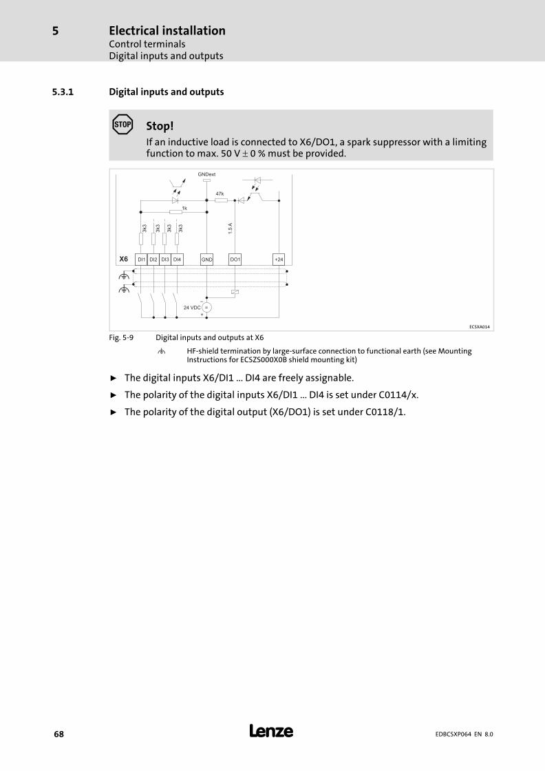
Electrical installationControl terminalsDigital inputs and outputs
5
� 68 EDBCSXP064 EN 8.0
5.3.1 Digital inputs and outputs
� Stop!
If an inductive load is connected to X6/DO1, a spark suppressor with a limitingfunction to max. 50 V � 0 % must be provided.
DI1 DI2 DI3 DI4
47k
GNDext
3k3
3k3
3k3
3k3
GND DO1X6
1.5
A
1k
+
_
24 VDC =
+24
�
�
ECSXA014
Fig. 5−9 Digital inputs and outputs at X6
� HF−shield termination by large−surface connection to functional earth (see MountingInstructions for ECSZS000X0B shield mounting kit)
ƒ The digital inputs X6/DI1 ... DI4 are freely assignable.
ƒ The polarity of the digital inputs X6/DI1 ... DI4 is set under C0114/x.
ƒ The polarity of the digital output (X6/DO1) is set under C0118/1.
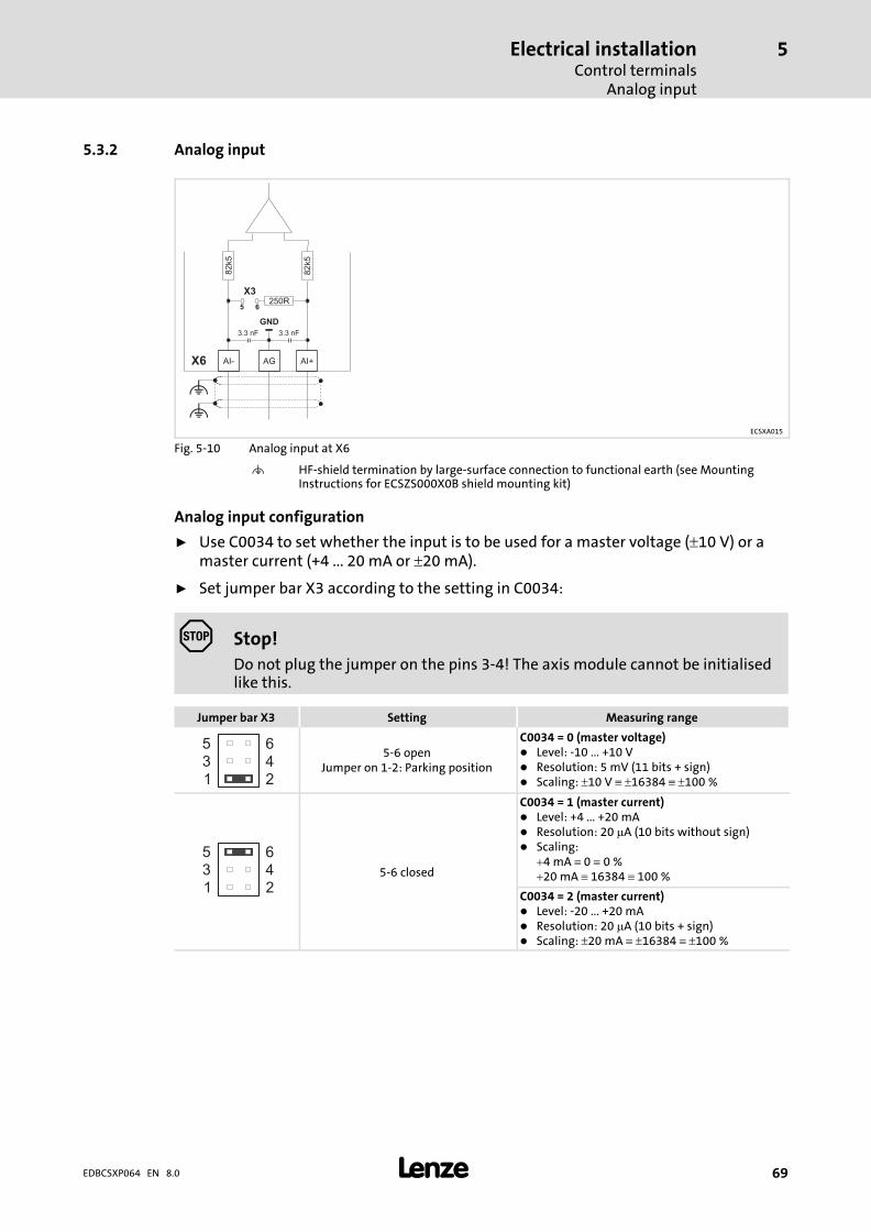
Electrical installationControl terminals
Analog input
5
� 69EDBCSXP064 EN 8.0
5.3.2 Analog input
AI- AG AI+
GND
82k5
X6
= =
82k5
250RX3
5 6
3.3 nF 3.3 nF
�
�ECSXA015
Fig. 5−10 Analog input at X6
� HF−shield termination by large−surface connection to functional earth (see MountingInstructions for ECSZS000X0B shield mounting kit)
Analog input configuration
ƒ Use C0034 to set whether the input is to be used for a master voltage (�10 V) or amaster current (+4 ... 20 mA or �20 mA).
ƒ Set jumper bar X3 according to the setting in C0034:
� Stop!
Do not plug the jumper on the pins 3−4! The axis module cannot be initialisedlike this.
Jumper bar X3 Setting Measuring range
642
531
5−6 openJumper on 1−2: Parking position
C0034 = 0 (master voltage)� Level: −10 ... +10 V� Resolution: 5 mV (11 bits + sign)� Scaling: �10 V � �16384 � �100 %
642
531
5−6 closed
C0034 = 1 (master current)� Level: +4 ... +20 mA� Resolution: 20 �A (10 bits without sign)� Scaling:
�4 mA � 0 � 0 %�20 mA � 16384 � 100 %
C0034 = 2 (master current)� Level: −20 ... +20 mA� Resolution: 20 �A (10 bits + sign)� Scaling: �20 mA � �16384 � �100 %
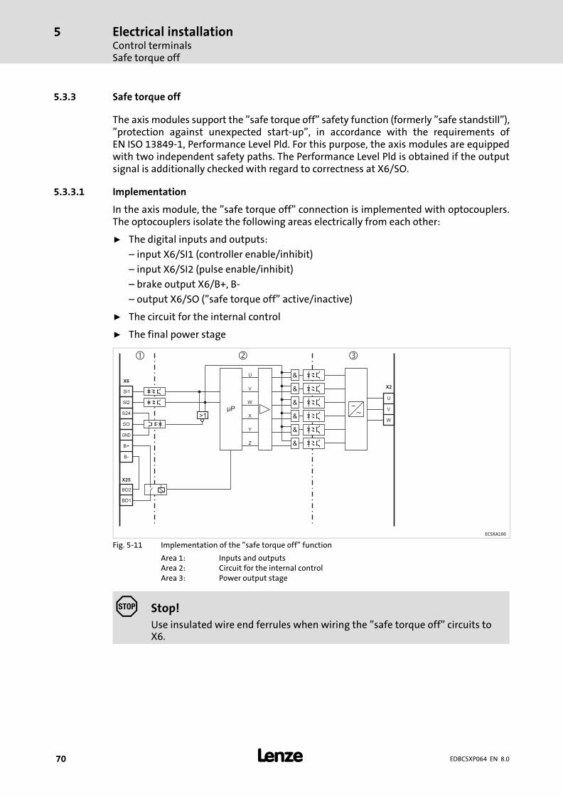
Electrical installationControl terminalsSafe torque off
5
� 70 EDBCSXP064 EN 8.0
5.3.3 Safe torque off
The axis modules support the "safe torque off" safety function (formerly "safe standstill"),"protection against unexpected start−up", in accordance with the requirements ofEN ISO 13849−1, Performance Level Pld. For this purpose, the axis modules are equippedwith two independent safety paths. The Performance Level Pld is obtained if the outputsignal is additionally checked with regard to correctness at X6/SO.
5.3.3.1 Implementation
In the axis module, the "safe torque off" connection is implemented with optocouplers.The optocouplers isolate the following areas electrically from each other:
ƒ The digital inputs and outputs:
– input X6/SI1 (controller enable/inhibit)
– input X6/SI2 (pulse enable/inhibit)
– brake output X6/B+, B−
– output X6/SO ("safe torque off" active/inactive)
ƒ The circuit for the internal control
ƒ The final power stage
>1µP
U
V
W
X
Y
Z
X6
X25
X2
Sl2
Sl1
U
V
WSO
GND
S24
B+
BD1
B-
BD2
� � �
&
&
&
&
&
&
ECSXA100
Fig. 5−11 Implementation of the "safe torque off" function
Area 1: Inputs and outputsArea 2: Circuit for the internal controlArea 3: Power output stage
� Stop!
Use insulated wire end ferrules when wiring the "safe torque off" circuits toX6.
Electrical installationControl terminals
Safe torque off
5
� 71EDBCSXP064 EN 8.0
5.3.3.2 Functional description
The "safe torque off" state can be initiated any time via the input terminals X6/SI1(controller enable/inhibit) and X6/SI2 (pulse enable/inhibit). For this purpose a LOW levelhas to be applied at both terminals:
ƒ X6/SI1 = LOW (controller inhibited):
The inverter is inhibited via the microcontroller system.
ƒ X6/SI2 = LOW (pulses inhibited):
The supply voltage for the optocouplers of the power section driver is switched off,i. e. the inverter can no longer be enabled and controlled via the microcontrollersystem.
The input signal at X6/SI2 to the hardware is additionally directed to themicrocontroller system and is evaluated for the state control there. For the externalfurther processing a HIGH level is output for the state "safe torque off active" at thedigital output X6/SO.
The control of the inverter thus is prevented by two different methods that areindependent of each other. Therefore an unexpected start−up by the motor is avoided.

Electrical installationControl terminalsSafe torque off
5
� 72 EDBCSXP064 EN 8.0
5.3.3.3 Important notes
� Danger!
When using the "safe torque off" function, additional measures are requiredfor "emergency stops"!
There is neither an electrical isolation between motor and axis module nor a"service" or "repair switch".
Possible consequences:
ƒ Death or severe injuries
ƒ Destruction or damage of the machine/drive
Protective measures:
An "emergency stop" requires the electrical isolation of the motor cable, e.g.by means of a central mains contactor with emergency stop wiring.
Installation/commissioning
ƒ The "safe torque off" function must only be installed and commissioned by qualified
personnel.
ƒ All control components (switches, relays, PLC, ...) and the control cabinet must meetthe requirements of EN ISO 13849. These include for instance:
– Switches, relays in enclosure IP54.
– Control cabinet in enclosure IP54.
– All other requirements can be found in EN ISO 13849.
ƒ Wiring with insulated wire end ferrules is essential.
ƒ All safety−relevant cables (e.g. control cable for the safety relay, feedback contact)outside the control cabinet must be protected, e.g. in the cable duct. It must beensured that short circuits between the individual cables cannot occur. For furthermeasures, see EN ISO 13849.
ƒ If force effects from outside (e.g. sagging of hanging loads) are to be expected whenthe "safe torque off" function is active, additional measures have to be taken (e.g.mechanical brakes).
During operation
ƒ After installation, the operator must check the "safe torque off" function.
ƒ The function check must be repeated at regular intervals, but no later than after oneyear.

Electrical installationControl terminals
Safe torque off
5
� 73EDBCSXP064 EN 8.0
5.3.3.4 Technical data
Terminal assignment
Plug connector X6
Terminal Function Level Electrical data
X6/S24 Low−voltage supply 18 ... 30 V DC0.7 A
X6/SO "Safe torque off" feedbackoutput
LOW During operation 24 V DC0.7 A (max. 1.4 A)Short−circuit−proofHIGH "Safe torque off" active
X6/SI1 Input 1 (controllerenable/inhibit)
LOW Controller inhibited LOW level:−3 ... +5 V−3 ... +1.5 mAHIGH level:+15 ... +30 V+2 ... +15 mAInput current at 24 V DC:8 mA per input
HIGH Controller enabled
X6/SI2 Input 2 (pulse enable/inhibit) LOW Pulses for power section areinhibited
HIGH Pulses for power section areenabled
Cable cross−sections and screw−tightening torques
Cable type Wire end ferrule Cable cross−section Starting torque Stripping length
Flexible
With insulated wireend ferrule
0.25 ... 1.5 mm2
(AWG 22 ... 16)0.22 ... 0.25 Nm
(1.95 ... 2.2 lb−in)
5 mm for screwconnections9 mm for springconnections
Without wire endferrule
Not permitted when the "Safe torque off" function is used

Electrical installationControl terminalsSafe torque off
5
� 74 EDBCSXP064 EN 8.0
5.3.3.5 Function check
ƒ After installation the operator must check the "safe torque off" function.
ƒ The function check must be repeated at regular intervals, after one year at thelatest.
� Stop!
If the function check leads to impermissible states at the terminals,commissioning cannot take place!
Test specifications
ƒ Check the circuitry with regard to correct function.
ƒ Check directly at the terminals whether the "safe torque off" function operatesfaultlessly in the axis module:
States of the "safe torque off" function on the axis module
Level at input terminalResulting level atoutput terminal
Impermissible level atoutput terminal
X6/SI1 X6/SI2 X6/SO X6/SO
LOW LOW HIGH LOW
LOW HIGH LOW
HIGHHIGH LOW LOW
HIGH HIGH LOW

Electrical installationControl terminals
Safe torque off
5
� 75EDBCSXP064 EN 8.0
5.3.3.6 Example: Wiring with electronic safety switching device "Pilz PNOZ e1vp" forPerformance Level Pld
Pilz
774195
Pilz
774195
T1 T2
Pilz
PNOZ e1vp 10s
Not-Halt/
Emergency stop
24V DC
Start
S34
24
14
S22
S12
Y6
S11
S21
Y4
Y7
A2
S36 A1
Y32
ECSxS/P/M/A
QSP
SI1
X25
X6
SI2
S24
S0
BD1
BD2
B-
B+
GND
DI1
24V DC
H1
ECSXA034
Fig. 5−12 Example: Wiring with "Pilz PNOZ e1vp 10s" safety switching device
T1 Test key 1T2 Test key 2
ƒ The motor is shut down in accordance with stop category 1 of EN 60204 when thesafety function is requested.
ƒ The delay time of the safety switching device and the quick stop deceleration timehave to be coordinated with the brake closing time.
ƒ The diode−capacitor combination prevents the test pulses of the safety switchingdevice from disturbing the smooth running of the motor, as otherwise a short−timeinhibit of the controller cannot be ruled out. The diode−capacitor combination can beprocured from the company Pilz (Pilz order number: 774195) as a complete terminalblock.
Electrical installationControl terminalsSafe torque off
5
� 76 EDBCSXP064 EN 8.0
Description of the function
ƒ The "PNOZ" safety switching device has a two−channel effect on the controller. Inthe case of an emergency stop request the two channels (terminals 14 and 24)become deenergised. The safety switching device monitors the diagnostic output ofthe controller.
ƒ The safety switching device is provided with test pulses at the output side, so thatshort circuits within the wiring are detected.
ƒ Diagnostics is effected via the wiring of diagnostic output SO to input Y7 of thesafety switching device. Y7 is the input of the feedback loop which has to be onHIGH level (+24 V) before the outputs 14 and 24 are activated. There is only HIGHlevel if both disconnecting paths have switched off.
ƒ At least once a year a manual test has to be carried out to verify the independenceand cutout ability of the two disconnecting paths.
Manual test of the disconnecting paths
ƒ The disconnecting paths have to be checked individually in succession.
ƒ When any test key (T1, T2) is pressed the motor has to become torquelessimmediately. Additionally the brake has to be applied, since the supply of the brakeis switched off via contact X6/B+.
ƒ When the safety switching device is switched off, or if both pushbuttons are pressedat the same time, the STO state has to be signalled via the indicator light H1. In allother states this message has to be inactive.
If a deviation from the response described above is determined, the controller must beswitched off immediately. Eliminate the fault before restarting the controller.
For obtaining a Performance Level PLd (SIL 2), only components which also comply with therequirements for PLd in accordance with EN ISO 13849−1 or SIL 2 in accordance with EN62061 are to be used in all upstream applications!
� Interconnection examples can be found in the download area (ApplicationKnowledge Base) at:www.Lenze.com
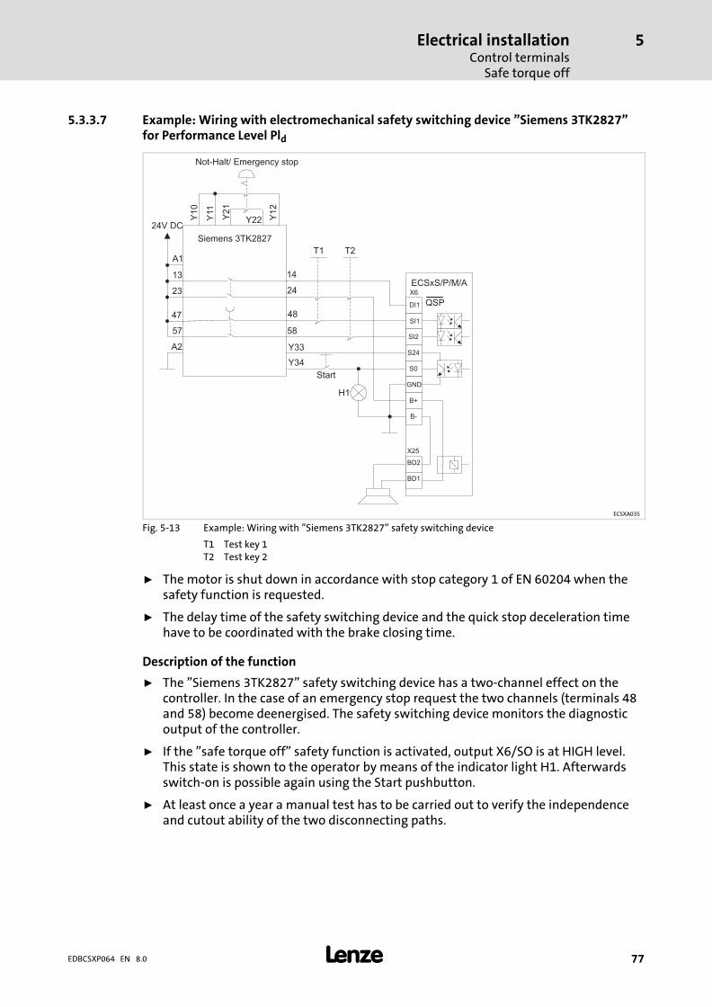
Electrical installationControl terminals
Safe torque off
5
� 77EDBCSXP064 EN 8.0
5.3.3.7 Example: Wiring with electromechanical safety switching device "Siemens 3TK2827"for Performance Level Pld
Start
Not-Halt/ Emergency stop
Siemens 3TK2827
Y22Y21
Y12
Y11
5857
4847
1413
Y10
Y34
Y33
24V DC
T1 T2
2423
A1
A2
ECSxS/P/M/A
QSP
SI1
X25
X6
SI2
S24
S0
BD1
BD2
B-
B+
GND
DI1
H1
ECSXA035
Fig. 5−13 Example: Wiring with "Siemens 3TK2827" safety switching device
T1 Test key 1T2 Test key 2
ƒ The motor is shut down in accordance with stop category 1 of EN 60204 when thesafety function is requested.
ƒ The delay time of the safety switching device and the quick stop deceleration timehave to be coordinated with the brake closing time.
Description of the function
ƒ The "Siemens 3TK2827" safety switching device has a two−channel effect on thecontroller. In the case of an emergency stop request the two channels (terminals 48and 58) become deenergised. The safety switching device monitors the diagnosticoutput of the controller.
ƒ If the "safe torque off" safety function is activated, output X6/SO is at HIGH level.This state is shown to the operator by means of the indicator light H1. Afterwardsswitch−on is possible again using the Start pushbutton.
ƒ At least once a year a manual test has to be carried out to verify the independenceand cutout ability of the two disconnecting paths.
Electrical installationControl terminalsSafe torque off
5
� 78 EDBCSXP064 EN 8.0
Manual test of the disconnecting paths
ƒ The disconnecting paths have to be checked individually in succession.
ƒ When any test key (T1, T2) is pressed the motor has to become torquelessimmediately. Additionally the brake has to be applied, since the supply of the brakeis switched off via contact X6/B+.
ƒ When the safety switching device is switched off, or if both pushbuttons are pressedat the same time, the STO state has to be signalled via the indicator light H1. In allother states this message has to be inactive.
If a deviation from the response described above is determined, the controller must beswitched off immediately. Eliminate the fault before restarting the controller.
For obtaining a Performance Level PLd (SIL 2), only components which also comply with therequirements for PLd in accordance with EN ISO 13849−1 or SIL 2 in accordance with EN62061 are to be used in all upstream applications!
� Interconnection examples can be found in the download area (ApplicationKnowledge Base) at:www.Lenze.com

Electrical installationAutomation interface (AIF)
5
� 79EDBCSXP064 EN 8.0
5.4 Automation interface (AIF)
The keypad XT or a communication module can be attached to or removed from theautomation interface (X1). This is also possible during operation.
ƒ The keypad XT serves to enter and visualise parameters and codes.
ƒ The communication modules serve to network the modules of the ECS servo systemwith the host system (PLC or PC).
The following combinations are possible:
Operating/communication module Type/order number Can be used together with
ECSxE ECSxS/P/M/A
Keypad XT EMZ9371BC � �
Diagnosis terminal (keypad XT with hand−held) E82ZBBXC � �
LECOM−A (RS232) EMF2102IB−V004 � �
LECOM−B (RS485) EMF2102IB−V002 � �
LECOM−A/B (RS232/485) EMF2102IB−V001 � �
LECOM−LI (optical fibre) EMF2102IB−V003 � �
LON EMF2141IB ˘ �
INTERBUS EMF2113IB ˘ �
PROFIBUS−DP EMF2133IB ˘ �
CANopen EMF2178IB ˘ �
DeviceNet EMF2179IB ˘ �
EtherCAT EMF2192IB � �
� Further information ....
on wiring and application of communication modules can be found in thecorresponding Mounting Instructions and Communication Manuals.

Electrical installationWiring of system bus (CAN)
5
� 80 EDBCSXP064 EN 8.0
5.5 Wiring of system bus (CAN)
� Note!
System bus (CAN)
The ECSxA...axis module can communicate with a higher−level host system(PLC) or further controllers via both CAN interfaces (X4 or X14).
MotionBus (CAN)
The "MotionBus (CAN)" term expresses the functionality of the CAN interfaceX4 in case of ECSxS/P/M... axis modules, where communication takes placeusing a higher−level host system (PLC) or further controllers exclusively via theX4 interface. Interface X14 (CAN−AUX) is exclusively used for parameter settingand diagnostics.
Basic wiring of the CAN bus networks
The two following schematic diagrams show drive systems with different master valueconcepts:
ƒ In Fig. 5−14 a higher−level control assumes the function of the master, e.g. ETC.
ƒ In Fig. 5−15 the function of the master is enabled by a controller intended as master.
In both representations, the master value transmission is effected via theMotionBus�(CAN), interface X4.
The system bus (CAN), interface X14, serves to diagnose and/or parameterise the drives.
PCM HMI
S S S
X4 X14 X14 X14X4 X4
MBSB
ECS_COB006
Fig. 5−14 MotionBus (CAN) with master control
PC
M
HMI
S S
X4 X14 X14 X14X4 X4
MBSB
ECS_COB007
Fig. 5−15 MotionBus (CAN) with controller as master
MB MotionBus (CAN), interface X4SB System bus (CAN), interface X14M MasterS SlavePC PC with the Lenze parameter setting and operating software (GDC, GDL, GDO)HMI HMI / operating unit

Electrical installationWiring of system bus (CAN)
5
� 81EDBCSXP064 EN 8.0
ECS_COB003
Fig. 5−16 Bus connections on the controller
Assignment of the plug connectors
X4 (CAN) X14 (CAN−AUX) Description
CH CAH CAN−HIGH
CL CAL CAN−LOW
CG CAG Reference potential
Specification of the transmission cable
We recommend the use of CAN cables in accordance with ISO 11898−2:
CAN cable in accordance with ISO 11898−2
Cable type Paired with shielding
Impedance 120 � (95 ... 140 �)
Cable resistance/cross−section
Cable length � 300 m � 70 m�/m / 0.25 � 0.34 mm2 (AWG22)
Cable length 301 � 1000 m � 40 m�/m / 0.5 mm2 (AWG20)
Signal propagation delay � 5 ns/m
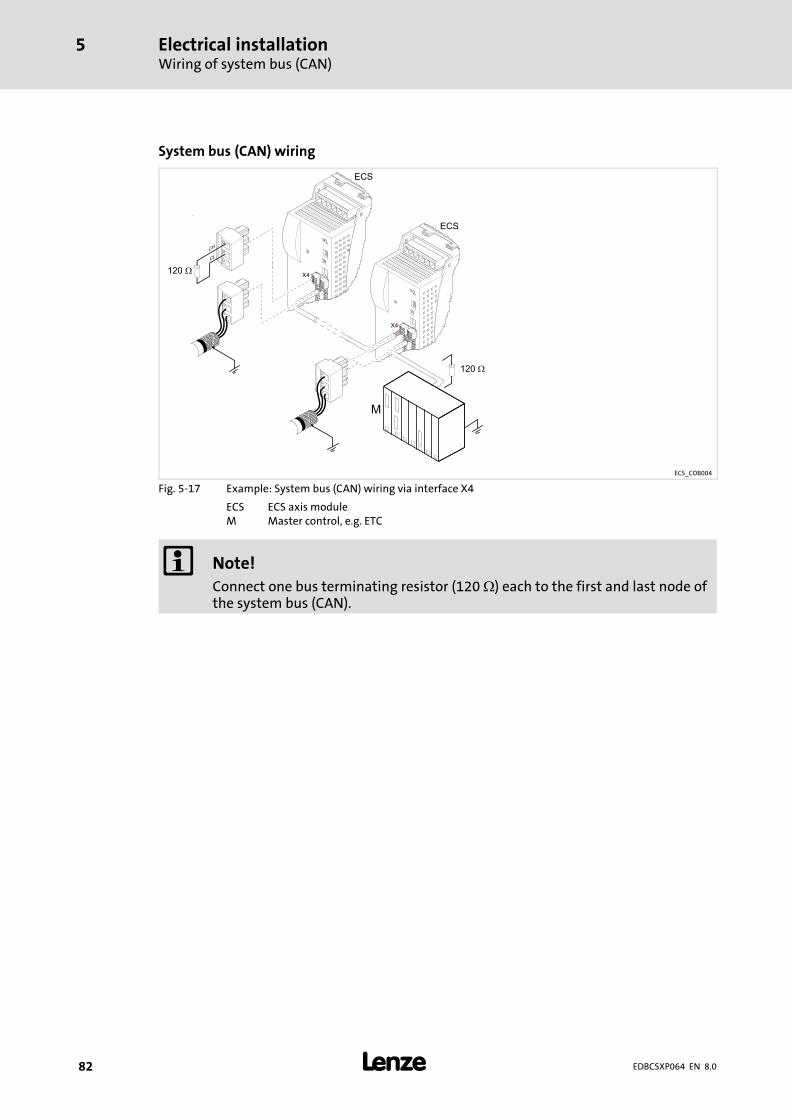
Electrical installationWiring of system bus (CAN)
5
� 82 EDBCSXP064 EN 8.0
System bus�(CAN) wiring
ECS_COB004
Fig. 5−17 Example: System bus (CAN) wiring via interface X4
ECS ECS axis moduleM Master control, e.g. ETC
� Note!
Connect one bus terminating resistor (120 �) each to the first and last node ofthe system bus (CAN).
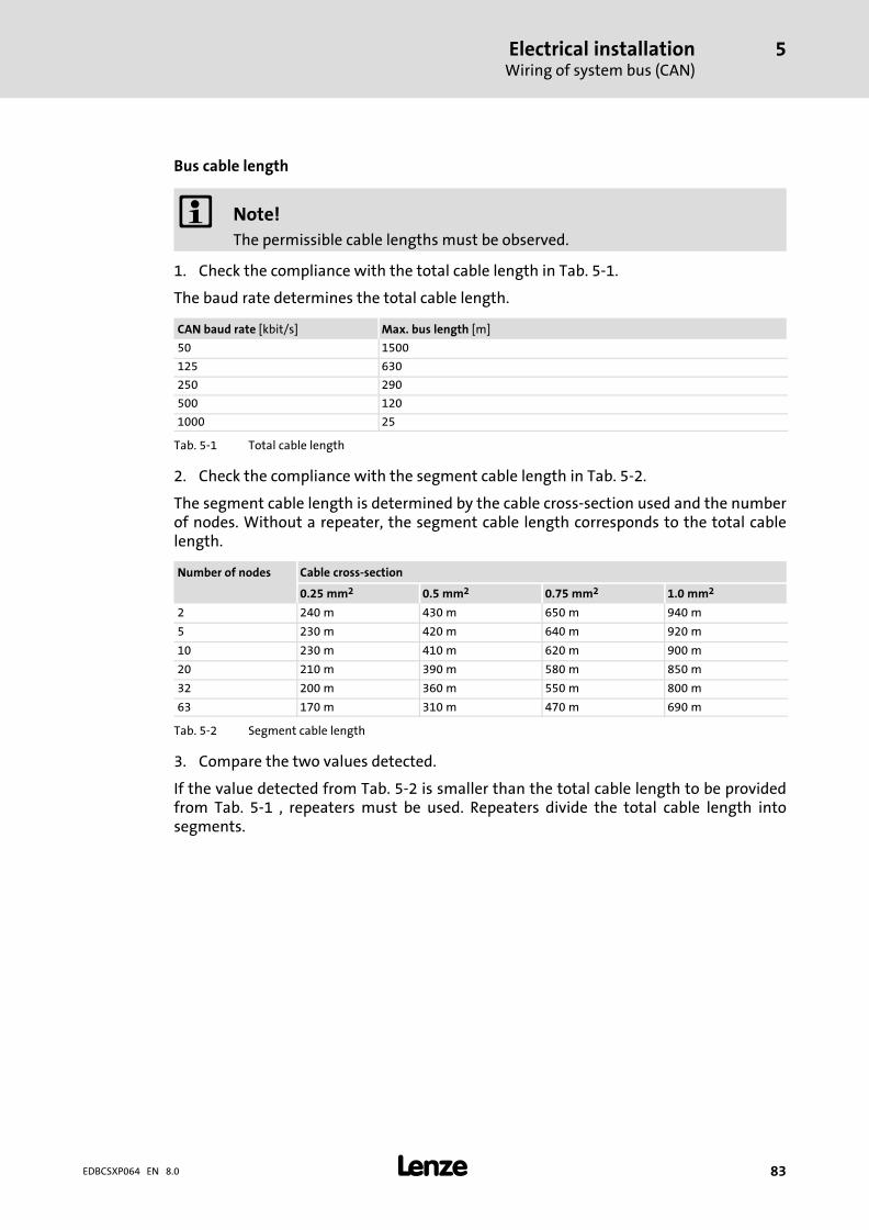
Electrical installationWiring of system bus (CAN)
5
� 83EDBCSXP064 EN 8.0
Bus cable length
� Note!
The permissible cable lengths must be observed.
1. Check the compliance with the total cable length in Tab. 5−1.
The baud rate determines the total cable length.
CAN baud rate [kbit/s] Max. bus length [m]
50 1500
125 630
250 290
500 120
1000 25
Tab. 5−1 Total cable length
2. Check the compliance with the segment cable length in Tab. 5−2.
The segment cable length is determined by the cable cross−section used and the numberof nodes. Without a repeater, the segment cable length corresponds to the total cablelength.
Number of nodes Cable cross−section
0.25 mm2 0.5 mm2 0.75 mm2 1.0 mm2
2 240 m 430 m 650 m 940 m
5 230 m 420 m 640 m 920 m
10 230 m 410 m 620 m 900 m
20 210 m 390 m 580 m 850 m
32 200 m 360 m 550 m 800 m
63 170 m 310 m 470 m 690 m
Tab. 5−2 Segment cable length
3. Compare the two values detected.
If the value detected from Tab. 5−2 is smaller than the total cable length to be providedfrom Tab. 5−1 , repeaters must be used. Repeaters divide the total cable length intosegments.

Electrical installationWiring of system bus (CAN)
5
� 84 EDBCSXP064 EN 8.0
Example: Selection help
Specifications
� Cable cross−section: 0.5 mm2 (according to cable specifications � 81)
� Number of nodes: 63
� Repeater: Lenze−repeater, type 2176 (cable reduction: 30 m)
For the max. number of nodes (63), the following cable lengths / number of repeaters fromthe specifications must be observed:
Baud rate [kbit/s] 50 120 250 500 1000
Max. cable length [m] 1500 630 290 120 25
Segment cable length [m] 310 310 290 120 25
Number of repeaters 5 2 − − −
Check repeater application
Given:
� Baud rate: 125 kbps
� Cable cross−section: 0.5 mm2
� Number of nodes: 28
� Cable length: 450 m
Procedure Cable length See
1. Total cable length at 125 kbps: 630 m Tab. 5−1
2. Segment cable length for 28 bus nodes and a cable cross−section of0.5 mm2:
360 m Tab. 5−2
3. Comparison: The value under point 2 is smaller than the required cable length of 450 m.
Conclusion
� It is not possible to use a cable length of 450 m without using a repeater.
� After 360 m (point 2) a repeater must be installed.
Result
� The Lenze repeater type 2176 is used (cable reduction: 30 m)
� Calculation of the maximum cable length:First segment: 360 mSecond segment: 360 m (according to Tab. 5−1) minus 30 m (cable reduction when a repeater is used)
� Maximum possible cable length with repeater: 690 m.� Now it is possible to use the required cable length.
� Note!
Repeaters are recommended as a
ƒ Service interface
Advantage: Trouble−free connecting during bus operation is possible.
ƒ Calibration interface
Advantage: Calibration/programming unit remains electrically isolated.
Electrical installationWiring of the feedback system
5
� 85EDBCSXP064 EN 8.0
5.6 Wiring of the feedback system
You can connect various feedback systems to the axis module:
ƒ Resolver on X7 (� 86)
ƒ Encoder on X8 (� 87)
– Incremental encoder with 5V−TTL level, RS−422
– SinCos encoder with zero track without Hiperface, signal level 1 Vss
– SinCos absolute value encoder (single−turn/multi−turn) with serial communication(Hiperface® interface), supply voltage 5 ... 8 V
� Note!
If a "safe isolation" acc. to EN 61140 between the encoder cable and motorcable (e.g. by using separating webs or separated trailing cables) is not ensuredon the entire cable length cable due to an installation on the system side, theencoder cable must be provided with an insulation resistance of 300 V. Lenzeencoder cables meet this requirement.
ƒ We recommend to use Lenze encoder cables for wiring.
ƒ In case of self−prepared cables– only use cables with shielded cores twisted in pairs.– Observe the notes on wiring/preparation on the following pages.
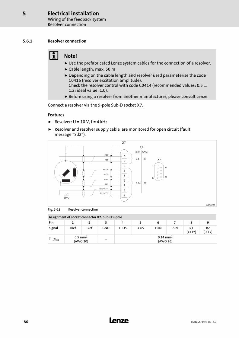
Electrical installationWiring of the feedback systemResolver connection
5
� 86 EDBCSXP064 EN 8.0
5.6.1 Resolver connection
� Note!
ƒ Use the prefabricated Lenze system cables for the connection of a resolver.
ƒ Cable length: max. 50 m
ƒ Depending on the cable length and resolver used parameterise the codeC0416 (resolver excitation amplitude).Check the resolver control with code C0414 (recommended values: 0.5 ...1.2; ideal value: 1.0).
ƒ Before using a resolver from another manufacturer, please consult Lenze.
Connect a resolver via the 9−pole Sub−D socket X7.
Features
ƒ Resolver: U = 10 V, f = 4 kHz
ƒ Resolver and resolver supply cable are monitored for open circuit (faultmessage "Sd2").
+REF
-REF
+COS
-COS
+SIN
-SIN
R1 (+KTY)
R2 (-KTY)
KTY
1
2
3
4
5
6
7
8
9
X7
0.14 26
0.5 20
mm2
AWG
�
1
5
6
9
X7
ECSXA022
Fig. 5−18 Resolver connection
Assignment of socket connector X7: Sub−D 9−pole
Pin 1 2 3 4 5 6 7 8 9
Signal +Ref −Ref GND +COS −COS +SIN −SIN R1(+KTY)
R2(−KTY)
0.5 mm2
(AWG 20)˘
0.14 mm2
(AWG 26)

Electrical installationWiring of the feedback system
Encoder connection
5
� 87EDBCSXP064 EN 8.0
5.6.2 Encoder connection
� Danger!
Valid when using an operating software up to and including V7.0:
When absolute value encoders are used, uncontrolled movements of the driveare possible!
If an absolute value encoder is disconnected from the axis module duringoperation, the fault OH3−TRIP occurs. If the absolute value encoder now isconnected to X8 again and a TRIP−RESET is carried out, the drive may start up inan uncontrolled manner with a high speed and a high torque. A SD8−TRIP willnot occur, as would be expected.
Possible consequences:
ƒ Death or severe injuries
ƒ Destruction or damage of the machine/drive
Protective measures:
ƒ If a fault (trip) occurs during commissioning when an absolute valueencoder is used, check the history buffer C0168. If an Sd8−TRIP is at thesecond or third place, a reinitialisation is absolutely necessary. For thispurpose, switch off and on again the 24−V supply of the control electronics.
Via the 9−pole Sub−D−plug X8, you can connect the following encoders:
ƒ Incremental encoder (TTL encoder)
– with two 5 V complementary signals (RS−422) that are electrically shifted by 90°.
– with zero track that can be connected optionally.
ƒ Sin/cos encoder (singleturn or multiturn rotary transducer)
– with supply voltage (5 ... 8 V).
– with serial communication. The initialisation time of the axis module is extended to approx. 2 s.
The controller supplies the encoder with voltage.
Use C0421 to set the supply voltage VCC (5 ... 8 V) to compensate, if required, the voltagedrop [�V] on the encoder cable:
�U � 2 � LL�[m] � R�m�[��m] � IG�[A]
�V Voltage drop on the encoder cable [V]
LL Cable length [m]
R/m Ohmic resistance per meter of cable length [�/m]
IG Encoder current [A]
� Stop!
Observe the permissible supply voltage of the encoder used. If the values inC0421 are set too high, the encoder can be destroyed!
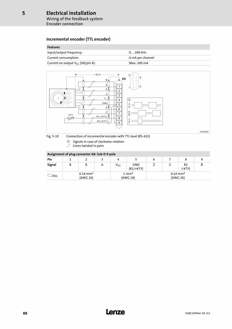
Electrical installationWiring of the feedback systemEncoder connection
5
� 88 EDBCSXP064 EN 8.0
Incremental encoder (TTL encoder)
Features
Input/output frequency: 0 ... 200 kHz
Current consumption: 6 mA per channel
Current on output VCC (X8/pin 4): Max. 200 mA
X8
5
1
9
6B
VCC
GND
Z
R1 (+KTY)
R2 (-KTY)
1
2
3
4
5
6
7
8
9
A
< 50 m
A
A
A
B
Z
B
B
Z
Z
KTY
�
ECSXA026
Fig. 5−19 Connection of incremental encoder with TTL level (RS−422)
� Signals in case of clockwise rotationCores twisted in pairs
Assignment of plug connector X8: Sub−D 9−pole
Pin 1 2 3 4 5 6 7 8 9
Signal B A A VCC GND(R1/+KTY)
Z Z R2(−KTY)
B
0.14 mm2
(AWG 26)1 mm2
(AWG 18)0.14 mm2
(AWG 26)
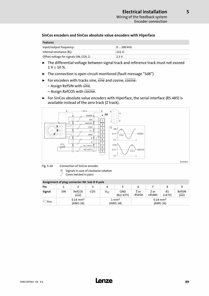
Electrical installationWiring of the feedback system
Encoder connection
5
� 89EDBCSXP064 EN 8.0
SinCos encoders and SinCos absolute value encoders with Hiperface
Features
Input/output frequency: 0 ... 200 kHz
Internal resistance (Ri): 221 �
Offset voltage for signals SIN, COS, Z: 2.5 V
ƒ The differential voltage between signal track and reference track must not exceed1 V � 10 %.
ƒ The connection is open−circuit monitored (fault message "Sd8")
ƒ For encoders with tracks sine, sine and cosine, cosine:
– Assign RefSIN with sine.
– Assign RefCOS with cosine.
ƒ For SinCos absolute value encoders with Hiperface, the serial interface (RS 485) isavailable instead of the zero track (Z track).
SIN
COS
0.5 V
0.5VRefSIN
RefCOS
2.5 V
2.5 V
0 V
0 V
�
X8
5
1
9
6SIN
VCC
GND
Z
R1 (+KTY)
R2 (-KTY)
1
2
3
4
5
6
7
8
9
COS
< 50 m
RefCOS
RefSIN
Z
KTY
ECSXA023
Fig. 5−20 Connection of SinCos encoder
� Signals in case of clockwise rotationCores twisted in pairs
Assignment of plug connector X8: Sub−D 9−pole
Pin 1 2 3 4 5 6 7 8 9
Signal SIN RefCOS(cos)
COS VCC GND(R2/−KTY)
Z or−RS458
Z or+RS485
R1(+KTY)
RefSIN(sin)
0.14 mm2
(AWG 26)1 mm2
(AWG 18)0.14 mm2
(AWG 26)
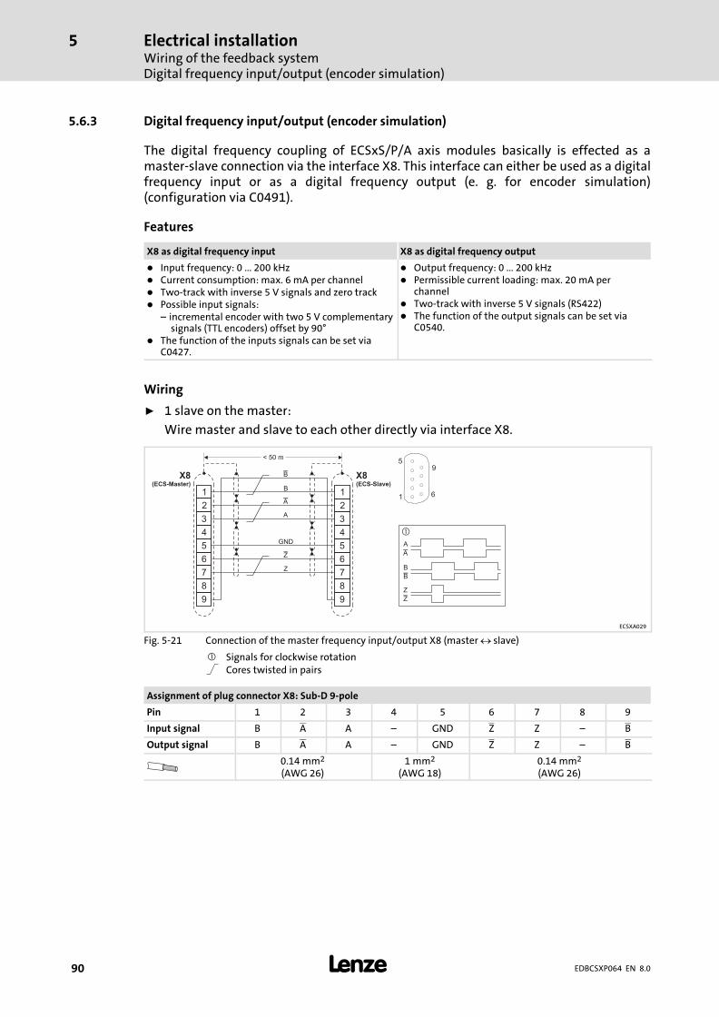
Electrical installationWiring of the feedback systemDigital frequency input/output (encoder simulation)
5
� 90 EDBCSXP064 EN 8.0
5.6.3 Digital frequency input/output (encoder simulation)
The digital frequency coupling of ECSxS/P/A axis modules basically is effected as amaster−slave connection via the interface X8. This interface can either be used as a digitalfrequency input or as a digital frequency output (e. g. for encoder simulation)(configuration via C0491).
Features
X8 as digital frequency input X8 as digital frequency output
� Input frequency: 0 ... 200 kHz� Current consumption: max. 6 mA per channel� Two−track with inverse 5 V signals and zero track� Possible input signals:
– incremental encoder with two 5 V complementarysignals (TTL encoders) offset by 90°
� The function of the inputs signals can be set viaC0427.
� Output frequency: 0 ... 200 kHz� Permissible current loading: max. 20 mA per
channel� Two−track with inverse 5 V signals (RS422)� The function of the output signals can be set via
C0540.
Wiring
ƒ 1 slave on the master:
Wire master and slave to each other directly via interface X8.
B
GND
Z
1
2
3
4
5
6
7
8
9
1
2
3
4
5
6
7
8
9
A
< 50 m
A
B
Z A
A
B
Z
B
Z
�
X8(ECS-Slave)
X8(ECS-Master)
5
1
9
6
ECSXA029
Fig. 5−21 Connection of the master frequency input/output X8 (master slave)
� Signals for clockwise rotationCores twisted in pairs
Assignment of plug connector X8: Sub−D 9−pole
Pin 1 2 3 4 5 6 7 8 9
Input signal B A A ˘ GND Z Z ˘ B
Output signal B A A ˘ GND Z Z ˘ B
0.14 mm2
(AWG 26)1 mm2
(AWG 18)0.14 mm2
(AWG 26)
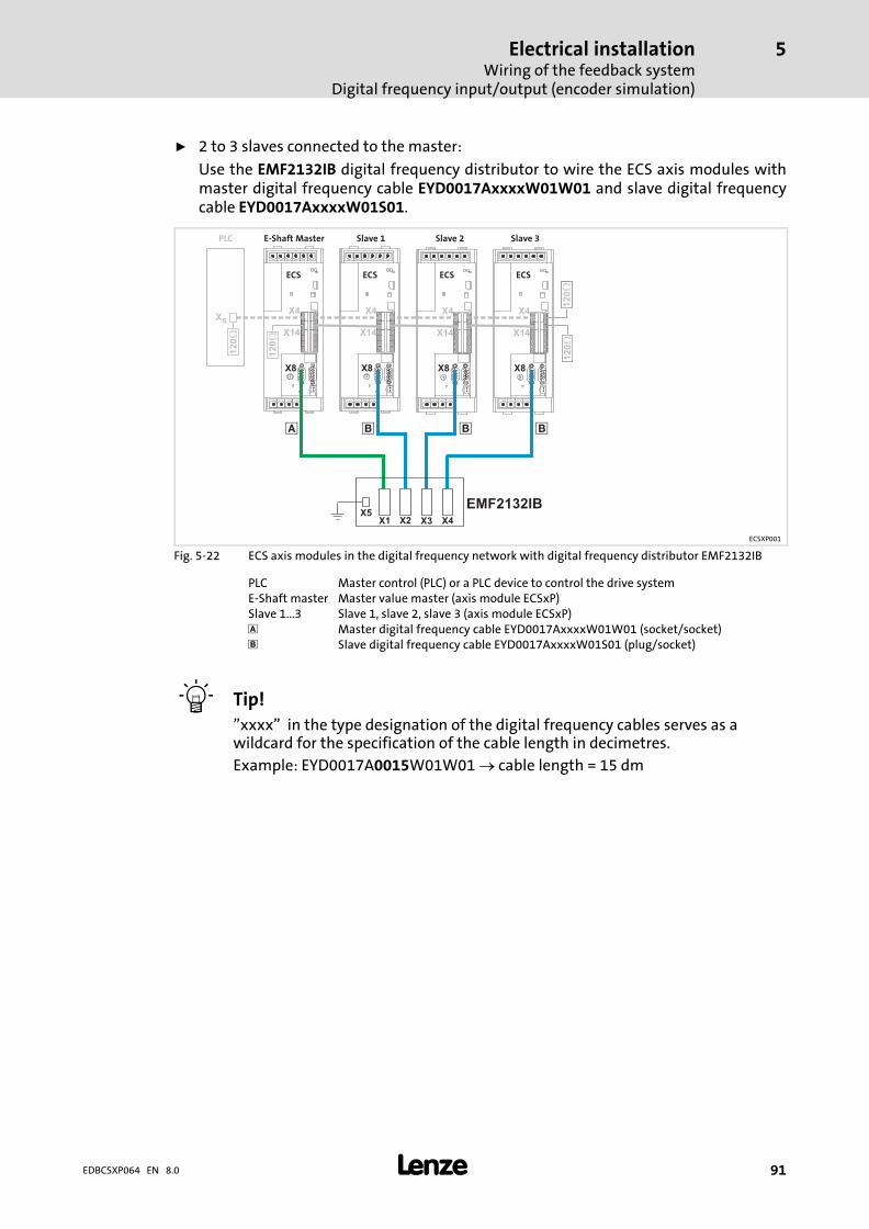
Electrical installationWiring of the feedback system
Digital frequency input/output (encoder simulation)
5
� 91EDBCSXP064 EN 8.0
ƒ 2 to 3 slaves connected to the master:
Use the EMF2132IB digital frequency distributor to wire the ECS axis modules withmaster digital frequency cable EYD0017AxxxxW01W01 and slave digital frequencycable EYD0017AxxxxW01S01.
X8 X8 X8X8
� � � �
E-Shaft Master Slave 3Slave 2Slave 1
XS
PLC
X4X4 X4X4
12
0
ECS ECS ECS ECS
X1X5
X2 X3 X4
EMF2132IB
12
01
20
X14X14 X14X14
12
01
20
12
0
ECSXP001
Fig. 5−22 ECS axis modules in the digital frequency network with digital frequency distributor EMF2132IB
PLC Master control (PLC) or a PLC device to control the drive systemE−Shaft master Master value master (axis module ECSxP)Slave 1...3 Slave 1, slave 2, slave 3 (axis module ECSxP) Master digital frequency cable EYD0017AxxxxW01W01 (socket/socket)� Slave digital frequency cable EYD0017AxxxxW01S01 (plug/socket)
� Tip!
"xxxx" in the type designation of the digital frequency cables serves as awildcard for the specification of the cable length in decimetres.
Example: EYD0017A0015W01W01 � cable length = 15 dm
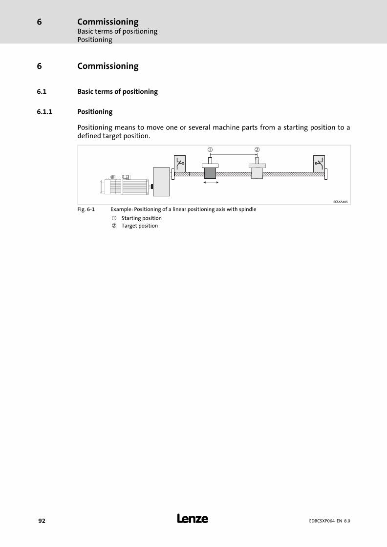
CommissioningBasic terms of positioningPositioning
6
� 92 EDBCSXP064 EN 8.0
6 Commissioning
6.1 Basic terms of positioning
6.1.1 Positioning
Positioning means to move one or several machine parts from a starting position to adefined target position.
� �
ECSXA405
Fig. 6−1 Example: Positioning of a linear positioning axis with spindle
� Starting position
� Target position

CommissioningBasic terms of positioning
Touch probe positioning
6
� 93EDBCSXP064 EN 8.0
6.1.2 Touch probe positioning
During the touch probe positioning process the drive at first travels towards the selectedtarget position until a mark sensor (touch probe signal) at the digital input X6/DI3 of theaxis module responds. When this has happened, the drive travels along a specified residualpath.
The residual path is defined by entering the target position in the following positioningprofile (profile number + 1). If several touch−probe signals occur during a touch probepositioning process, the residual path is measured from the last touch−probe signal.
� Note!
The touch probe positioning profile before its start is not monitored withregard to software limit positions ( 237). If one of the software limitpositions is reached during touch probe positioning, a fault and a quick stop(QSP) are activated.
v [m/s]
t [s]
�
�
ECSXA412
Fig. 6−2 Example: Touch probe positioning with a linear positioning axis
� Sensor mark transmits touch probe signal
� Residual path
To suppress further touch probe signals, you can set a debounce time for the touch probeinput X6/DI3 under C3036. After touch probe identification, further touch probe signal willbe ignored for the time selected under C3036.
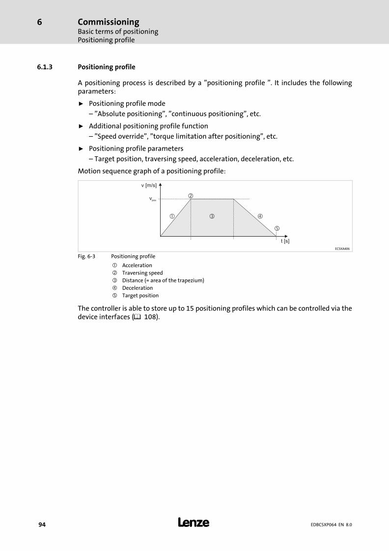
CommissioningBasic terms of positioningPositioning profile
6
� 94 EDBCSXP064 EN 8.0
6.1.3 Positioning profile
A positioning process is described by a "positioning profile ". It includes the followingparameters:
ƒ Positioning profile mode
– "Absolute positioning", "continuous positioning", etc.
ƒ Additional positioning profile function
– "Speed override", "torque limitation after positioning", etc.
ƒ Positioning profile parameters
– Target position, traversing speed, acceleration, deceleration, etc.
Motion sequence graph of a positioning profile:
v [m/s]
t [s]
��
�
�
vpos
�
ECSXA406
Fig. 6−3 Positioning profile
� Acceleration
� Traversing speed
� Distance (= area of the trapezium)
� Deceleration
Target position
The controller is able to store up to 15 positioning profiles which can be controlled via thedevice interfaces ( 108).
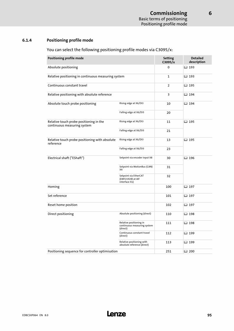
CommissioningBasic terms of positioning
Positioning profile mode
6
� 95EDBCSXP064 EN 8.0
6.1.4 Positioning profile mode
You can select the following positioning profile modes via C3095/x:
Positioning profile mode SettingC3095/x
Detaileddescription
Absolute positioning 0 � 193
Relative positioning in continuous measuring system 1 � 193
Continuous constant travel 2 � 195
Relative positioning with absolute reference 3 � 194
Absolute touch probe positioning Rising edge at X6/DI3 10 � 194
Falling edge at X6/DI3 20
Relative touch probe positioning in thecontinuous measuring system
Rising edge at X6/DI3 11 � 195
Falling edge at X6/DI3 21
Relative touch probe positioning with absolutereference
Rising edge at X6/DI3 13 � 195
Falling edge at X6/DI3 23
Electrical shaft ("EShaft") Setpoint via encoder input X8 30 � 196
Setpoint via MotionBus (CAN)X4
31
Setpoint via EtherCAT(EMF2192IB at AIFinterface X1)
32
Homing 100 � 197
Set reference 101 � 197
Reset home position 102 � 197
Direct positioning Absolute positioning (direct) 110 � 198
Relative positioning incontinuous measuring system(direct)
111 � 198
Continuous constant travel(direct)
112 � 199
Relative positioning withabsolute reference (direct)
113 � 199
Positioning sequence for controller optimisation 251 � 200
CommissioningBasic terms of positioningAdditional functions of the positioning profile (C3096/x)
6
� 96 EDBCSXP064 EN 8.0
6.1.5 Additional functions of the positioning profile (C3096/x)
ƒ Speed override
– The term "Override" refers to the variation of the speed set in the positioningprofile via the analog input (10 V � 100 %) and/or by means of the process dataobject (PDO) via CAN, AIF, C4040.
ƒ Torque limitation after positioning
– After completion of positioning the torque is limited to a defined value after acertain time has elapsed.
ƒ Profile continuation after profile abort
– If the profile continuation function is activated and traversing of the profile isstopped, this profile can be completed with a renewed profile start.
– If the profile continuation function is deactivated, the stopped positioning processis considered to be completed when the profile is started anew (changing back tothe "Positioning" state).
ƒ Immediate profile change during positioning(direct change)
– If a new profile number is defined during a positioning process, the newpositioning profile is started immediately without completing the previouspositioning process.
– Condition: Direct Change must be activated for the new profile (C3096).
ƒ Stretch factor for "electrical shaft"
– The "electrical shaft" drive function is used for line drives when several drives areto be traversed with synchronous phase angle and speed, for instance, becausethey act upon the same web. Via an adjustable stretch factor (profile parametersC3097/C3098), the web tension can be varied between the contact points of thedrives at the web (electronic gearbox).
– The machine parameters for the gearbox ratio (C1202/C1203, � 103) only havean effect on positioning and have no impact on the "electrical shaft" drivefunction.
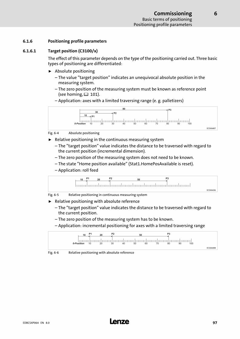
CommissioningBasic terms of positioning
Positioning profile parameters
6
� 97EDBCSXP064 EN 8.0
6.1.6 Positioning profile parameters
6.1.6.1 Target position (C3100/x)
The effect of this parameter depends on the type of the positioning carried out. Three basictypes of positioning are differentiated:
ƒ Absolute positioning
– The value "target position" indicates an unequivocal absolute position in themeasuring system.
– The zero position of the measuring system must be known as reference point(see homing, � 101).
– Application: axes with a limited traversing range (e. g. palletizers)
0-Position 10 20 30 40 50 60 70 80 90 100
10
30
80
P1
P2
P3
ECSXA407
Fig. 6−4 Absolute positioning
ƒ Relative positioning in the continuous measuring system
– The "target position" value indicates the distance to be traversed with regard tothe current position (incremental dimension).
– The zero position of the measuring system does not need to be known.
– The state "Home position available" (Stat1.HomePosAvailable is reset).
– Application: roll feed
10 20 50P3P2P1
ECSXA436
Fig. 6−5 Relative positioning in continuous measuring system
ƒ Relative positioning with absolute reference
– The "target position" value indicates the distance to be traversed with regard tothe current position.
– The zero position of the measuring system has to be known.
– Application: incremental positioning for axes with a limited traversing range
0-Position 10 20 30 40 50 60 70 80 90 100
10 20 50P3P2P1
ECSXA408
Fig. 6−6 Relative positioning with absolute reference
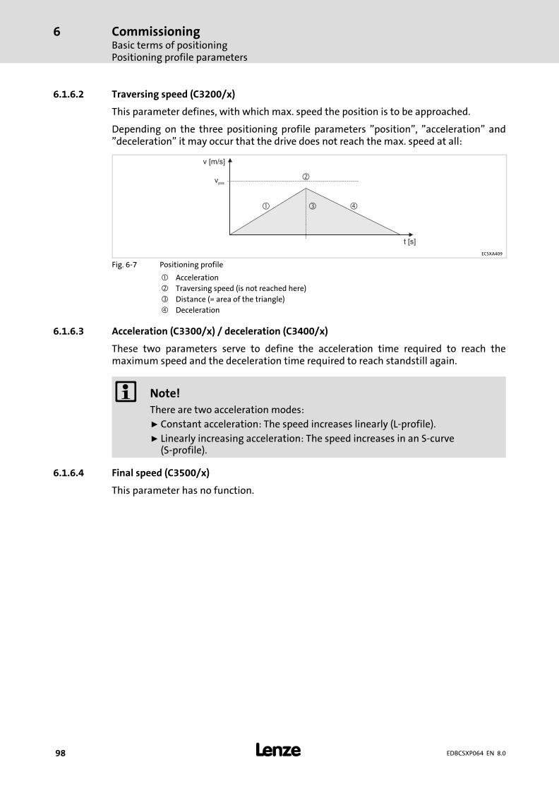
CommissioningBasic terms of positioningPositioning profile parameters
6
� 98 EDBCSXP064 EN 8.0
6.1.6.2 Traversing speed (C3200/x)
This parameter defines, with which max. speed the position is to be approached.
Depending on the three positioning profile parameters "position", "acceleration" and"deceleration" it may occur that the drive does not reach the max. speed at all:
v [m/s]
t [s]
��
�
�
vpos
ECSXA409
Fig. 6−7 Positioning profile
� Acceleration
� Traversing speed (is not reached here)
� Distance (= area of the triangle)
� Deceleration
6.1.6.3 Acceleration (C3300/x) / deceleration (C3400/x)
These two parameters serve to define the acceleration time required to reach themaximum speed and the deceleration time required to reach standstill again.
� Note!
There are two acceleration modes:
ƒ Constant acceleration: The speed increases linearly (L−profile).
ƒ Linearly increasing acceleration: The speed increases in an S−curve(S−profile).
6.1.6.4 Final speed (C3500/x)
This parameter has no function.

CommissioningBasic terms of positioning
Positioning profile parameters
6
� 99EDBCSXP064 EN 8.0
6.1.6.5 Jerk time (C3600/x) L−profile, S−profile
The setting of the jerk time under C3600/x serves to change over between L profile and Sprofile for generating the travel profile.
ƒ Jerk time = 0, L profile is active (Lenze setting):
The positioning profile is generated with linear ramps. All positioning profile modes(C3095/x) can be used.
ƒ Jerk time � 0, S profile is active:
The positioning profile is generated with S−shaped ramps. This ramp form cannot beused with the touch probe positioning profile modes C3095/x = 10 ... 23 and neitherwith positioning profiles with the activated additional function "Immediate profilechange" (C3096/x.Bit5 = 1).
The jerk time set under C3600/x is a measure for smoothening the speed curve withS−ramps. The jerk time corresponds to the ramp time (tjerk), after which the acceleration setin the positioning profile is reached, starting from acceleration 0.
The smoothening of the speed curve with S−ramps serves to limit the jerk and thus for aprotection of the machine mechanics.
� Note!
If disproportionately high jerk times (tjerk) are set for short acceleration phases(tacc), the profile may be generated incorrectly.
Example:
v = 100 mm/s, a = 1000 mm/s2
tacc = v / a = 0.1 s
tjerk = 0.05 s
For this reason, set only plausible jerk times for the S−ramps under C3600/x.These must not exceed half the value of tacc.

CommissioningBasic terms of positioningPositioning profile parameters
6
� 100 EDBCSXP064 EN 8.0
V
t
t
a
tJerk
1 2 3 4 5 6 7 8 9
Vel
Acc
Dec
t jerk t jerk jerkt t jerk
�
�
ECSXA429
Fig. 6−8 Jerk time C3600/x
Process without jerk limitation
� Process with jerk limitation
1 Standstill2 Accelerating with increasing acceleration (limited jerk)3 Accelerating with constant acceleration acc. to positioning profile (Acc, C3300/x)4 Accelerating with decreasing acceleration (limited jerk)5 Travelling with traversing speed acc. to positioning profile (Vel, C3200/x)6 Decelerating with increasing deceleration (limited jerk)7 Decelerating with constant deceleration acc. to positioning profile (Dec, C3400/x)8 Decelerating with decreasing deceleration (limited jerk)9 Standstill (target position reached)

CommissioningBasic terms of positioning
Setting of manual jog (inching mode)
6
� 101EDBCSXP064 EN 8.0
6.1.7 Setting of manual jog (inching mode)
"Manual jog" means running the drive by manual operation.
��
ECSXA419
Fig. 6−9 Manual jog (inching mode)
ƒ The parameters "traversing speed", "acceleration" and "deceleration" can also be setfor manual jog. ( 173)
6.1.8 Homing
By means of homing, the zero position is defined within the physically possible traversingrange of the machine. Thus, the reference of the measuring systems to the machine isestablished.
0-Position10 20 30 40 50 60-10
ECSXA418
Fig. 6−10 Homing (defining the zero position)
The zero position (home position) can be defined by homing or by setting a reference:
ƒ During homing the drive traverses in a defined mode (homing mode) to detect thezero position on its own and in a reproducible manner.
ƒ When homing is carried out, the current position is defined as zero position (homeposition).

CommissioningBasic terms of positioningMeasuring system for positioning
6
� 102 EDBCSXP064 EN 8.0
6.1.9 Measuring system for positioning
Zero position
C3011, C3012
C3041
SW-LimNeg
Neg. limit switch Pos. limit switch
Target positionSW-LimPos
C3040
Home position
100 20 30 40 50 60 70 80-10
30 P1
ECSXA404
Fig. 6−11 Measuring system for the positioning
The measuring system for positioning has the following features:
ƒ The zero position of the measuring system has a firm reference to the machine dueto the home position.
ƒ The home position is found out by homing.
ƒ The software limit positions (SW−LimNeg, SW−LimPos) refer to the zero position.
ƒ The zero position can be shifted via the offset values C3011 (home offset) andC3012 (measure offset)( 187).
ƒ The data for C3051 (actual position in units) and C3056 (target position inincrements) refer to the zero position of the measuring system.
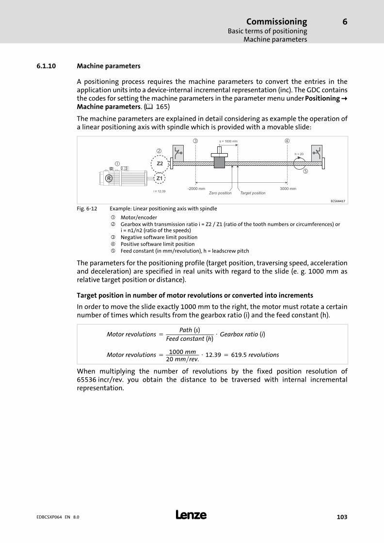
CommissioningBasic terms of positioning
Machine parameters
6
� 103EDBCSXP064 EN 8.0
6.1.10 Machine parameters
A positioning process requires the machine parameters to convert the entries in theapplication units into a device−internal incremental representation (inc). The GDC containsthe codes for setting the machine parameters in the parameter menu under Positioning �Machine parameters. ( 165)
The machine parameters are explained in detail considering as example the operation ofa linear positioning axis with spindle which is provided with a movable slide:
Zero position3000 mm-2000 mm
�
�
�
�
�
i = 12.39
h = 20
s = 1000 mm
Target position
Z2
Z1R
ECSXA417
Fig. 6−12 Example: Linear positioning axis with spindle
� Motor/encoder� Gearbox with transmission ratio i = Z2 / Z1 (ratio of the tooth numbers or circumferences) or
i = n1/n2 (ratio of the speeds)� Negative software limit position� Positive software limit position Feed constant (in mm/revolution), h = leadscrew pitch
The parameters for the positioning profile (target position, traversing speed, accelerationand deceleration) are specified in real units with regard to the slide (e. g. 1000 mm asrelative target position or distance).
Target position in number of motor revolutions or converted into increments
In order to move the slide exactly 1000 mm to the right, the motor must rotate a certainnumber of times which results from the gearbox ratio (i) and the feed constant (h).
Motor�revolutions � 1000�mm20�mm�rev.
� 12.39 � 619.5�revolutions
Motor�revolutions �Path�(s)
Feed�constant�(h)� Gearbox�ratio�(i)
When multiplying the number of revolutions by the fixed position resolution of65536 incr/rev. you obtain the distance to be traversed with internal incrementalrepresentation.

CommissioningBasic terms of positioningMachine parameters
6
� 104 EDBCSXP064 EN 8.0
Gearbox ratio (C1202/C1203)
The gearbox ratio specifies the number of revolutions of the motor axis at which thespindle revolves exactly once.
It is entered into the codes C1202 (gearbox factor numerator) and C1203 (gearbox factordenominator). For the example described above, it follows that:
Gearbox�ratio�(i) �1239�[rev.�min.]
100�[rev.�min.]� 12.39
Gearbox�ratio�(i) �nMotor�[rev.�min.]
nGearbox_output�[rev.�min.]� Z2
Z1� C1202
C1203
� Note!
The gearbox ratio regarding the ratio of speeds (nMotor/nGearbox) is enteredinverse to the ratio of number of teeth (Z2/Z1) and the circumferences(U2/U1).
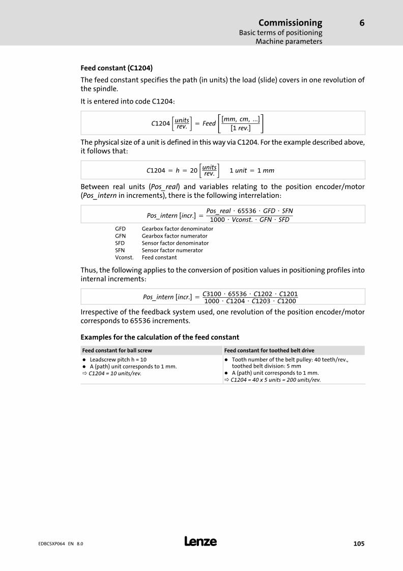
CommissioningBasic terms of positioning
Machine parameters
6
� 105EDBCSXP064 EN 8.0
Feed constant (C1204)
The feed constant specifies the path (in units) the load (slide) covers in one revolution ofthe spindle.
It is entered into code C1204:
C1204��unitsrev.
� � Feed��[mm,� cm,� ���][1�rev.]
�The physical size of a unit is defined in this way via C1204. For the example described above,it follows that:
C1204 � h � 20��unitsrev.
�������1�unit � 1�mm
Between real units (Pos_real) and variables relating to the position encoder/motor(Pos_intern in increments), there is the following interrelation:
Pos_intern�[incr.] �Pos_real � 65536 � GFD � SFN
1000 � Vconst. � GFN � SFD
GFD Gearbox factor denominatorGFN Gearbox factor numeratorSFD Sensor factor denominatorSFN Sensor factor numeratorVconst. Feed constant
Thus, the following applies to the conversion of position values in positioning profiles intointernal increments:
Pos_intern�[incr.] � C3100 � 65536 � C1202 � C12011000 � C1204 � C1203 � C1200
Irrespective of the feedback system used, one revolution of the position encoder/motorcorresponds to 65536 increments.
Examples for the calculation of the feed constant
Feed constant for ball screw Feed constant for toothed belt drive
� Leadscrew pitch h = 10� A (path) unit corresponds to 1 mm. C1204 = 10 units/rev.
� Tooth number of the belt pulley: 40 teeth/rev.,toothed belt division: 5 mm
� A (path) unit corresponds to 1 mm. C1204 = 40 x 5 units = 200 units/rev.

CommissioningBasic terms of positioningMachine parameters
6
� 106 EDBCSXP064 EN 8.0
Maximum target position selection (C4265)
The maximum target position selection results from the possible traversing range of16384 position encoder revolutions converted into real units.
C4265 � 16384�[rev.] � 65536�[incr.�rev.] � 10000 � C1204 � C1203 � C120065536 � C1202 � C1201
C4265 is limited to �214000.0000 units.
Position resolution (C4266)
Number of increments per unit specified
ƒ Due to the internal remainder considered, the lowest−order position can vary about1.
ƒ 1 revolution of position encoder � 65536 increments.
ƒ Value range: 0 ... 2140000000
Maximum traversing speed (C1240)
Via C1240 you can define the maximum traversing speed (vmax) for the machine. Thespeed specifications in the positioning profiles are limited internally to vmax. vmax shouldbe set lower than the velocity possible at maximum motor speed (C0011). The value canbe calculated according to the following formula:
C1240 � C0011 � C1204 � C120360 � C1202
vmax � nmax �vk
60 � i
� Tip!
The maximum input value for vmax can be read out via C3060.
Maximum acceleration/deceleration (C1250)
The maximum permissible acceleration or deceleration for positioning processes amongother things depends on the motor torque and the moment of inertia of the entiremechanics driven during the positioning process.

CommissioningBasic terms of positioningElectrical shaft ("EShaft")
6
� 107EDBCSXP064 EN 8.0
Software limit positions (C3040/C3041)
As well as defining the zero position it is important to define the limits of travel range toavoid damages of the system, e. g. at manual control. These limits (limit switches/limitpositions) can be defined by hardware and software:
ƒ Hardware limit switches are linked with the digital inputs of the controller; whenbeing activated, a certain action is carried out (e. g. quick stop).
ƒ Software limit positions additionally limit the possible travel range within thehardware limit switches and check on the drive level whether a position can beapproached.
Information on the operating mode and setting of the software limit positions can befound on � 237.
0-Position10 20 30 40 50 60-10
� � � �
ECSXA411
Fig. 6−13 Example: Limit positions of a linear positioning axis with spindle
� Negative hardware limit switch
� Negative software limit position, C3041 = −10 units
� Positive software limit position, C3040 = +50 units
� Positive hardware limit switch
6.1.11 Electrical shaft ("EShaft")
The "electrical shaft" drive function is used for line drives when several drives are to betraversed with synchronous phase angle and speed, for instance, because they act uponthe same web. Via an adjustable stretch factor, the web tension can be varied between thecontact points of the drives at the web.
Detailed information on the configuration of the "Electrical shaft" drive function can befound from � 211.

CommissioningBasic terms of positioningDevice structure and interfaces to the higher−level control
6
� 108 EDBCSXP064 EN 8.0
6.1.12 Device structure and interfaces to the higher−level control
The ECSxP axis module with the "Posi and Shaft" application program requires ahigher−level control (e. g. Lenze Drive PLC) for the coordination of the positioning process.
The "Posi and Shaft" application program enables input and storage of individualpositioning profiles and the accompanying profile parameters (target position, traversingspeed, acceleration, etc.). The selection, starting and timely sequencing of the positioningprofiles must be carried out by a higher−level control.
Profile 15
Profile ...
Profile 2
Profile 1
v
tDirect modes
Control word:
Profile No.
CinhJog CWJog CCWTRIP-RESET...
Prof enable
HomingManual operationPoint to point positioningTouch probe positioningEShaft
Brake logic
Positioning Control
Profiles
ECSxPCustomer PLC
MotorControl
DigIn
DFIN
X6/DI1
Digitalfrequency
X7
X6/DI2X6/DI3X6/DI4
DigOut
Internal relay
X6/DO1
X2
5/B
1
X2
5/B
2
DigIn mapping
DigOut mapping
AuxProfileBusyProfile dataProfEnable
C4012
C4011
C4010
PosProfiler
Byte1
Byte1
Byte1
Byte1
Byte1
Byte1
Byte1
Byte1
Byte1
Byte1
Byte2
Byte2
Byte2
Byte2
Byte2
Byte2
Byte2
Byte2
Byte2
Byte2
Byte3
Byte3
Byte3
Byte3
Byte3
Byte3
Byte3
Byte3
Byte3
Byte3
Byte3
Byte4
Byte4
Byte4
Byte4
Byte4
Byte4
Byte4
Byte4
Byte5
Byte5
Byte5
Byte5
Byte5
Byte5
Byte5
Byte5
Byte5
Byte6
Byte6
Byte6
Byte6
Byte6
Byte6
Byte6
Byte6
Byte6
Byte7
Byte7
Byte7
Byte7
Byte7
Byte7
Byte7
Byte7
Byte7
Byte8
Byte8
Byte8
Byte8
Byte8
Byte8
Byte8
Byte8
Byte8
Co
ntr
olw
ord
Co
ntr
olw
ord
Co
ntr
olw
ordC
on
tro
lw
ord
Process data OutProcess data In
Processdata
channel
Sta
tus
wo
rd1
Sta
tus
wo
rd2
1
:
2
n
0
0
X8
X6
X24X25
X7
CAN-Out
CAN-AUX-Out
AIF-Out
X14
C4045C4046...C4050
X1
Digitalfrequency
Encodersimulation
X4
C4040 AppControlC4041 AppWord 2C4042 AppWord 3/4
Parameter datachannel
X6
CAN-In
CAN-AUX-In
AIF-In
X14
X1
X4
ECSXA400
Fig. 6−14 Structure of ECS "Posi and Shaft"

CommissioningBasic terms of positioning
Device structure and interfaces to the higher−level control
6
� 109EDBCSXP064 EN 8.0
The following control interfaces are available for the controller under code C4010:
ƒ Automation interface (AIF) X1
– 4 process data words (in conjunction with the EMF2192IB EtherCATcommunication module, sync−controlled via the terminal X6/DI1)
ƒ MotionBus (CAN) connection X4
– CAN1 (process data object 1, PDO1, sync−controlled)
– CAN3 (process data object 3, PDO3, cyclic)
ƒ System bus (CANaux) connection X14
– CANaux1 (process data object 1, PDO1, sync−controlled)
– CANaux2 (process data object 2, PDO2, cyclic)
ƒ Control via codes C4040, C4041, C4042 through a parameter data channel, e.g. AIF,CAN, CAN−AUX, LECOM (for commissioning and test purposes)
The interface between the control and the ECSxP axis module is mainly determined by thecontrol word (Ctrl1) and the two status words (Stat1) and (Stat2). They contain all controland status bits required for controlling the process.
The most important control bits from the control: ( 158):
Bit Designation Function
3 Quick stop (QSP) Quick stop
4 PNoSet_1 Selection of the positioning profile (binary coded)
5 PNoSet_2
6 PNoSet_4
7 PNoSet_8
8 ProfEnable Start of the selected positioning profile
9 CINH Controller inhibit
11 TripReset Reset fault message
12 JogCCW Manual jog (inching mode)
13 JogCW
The most important status bits ("Stat1") to the control ( 161):
Bit Designation Function
6 PNoAct_1 Feedback of the currently active positioning profile (binary coded)
7 PNoAct_2
8 PNoAct_4
9 PNoAct_8
13 HomePosAvailable Home position known
14 InTarget Positioning target reached
15 DwellTime The dwell time has expired after profile generator setpoint has reached thetarget position.
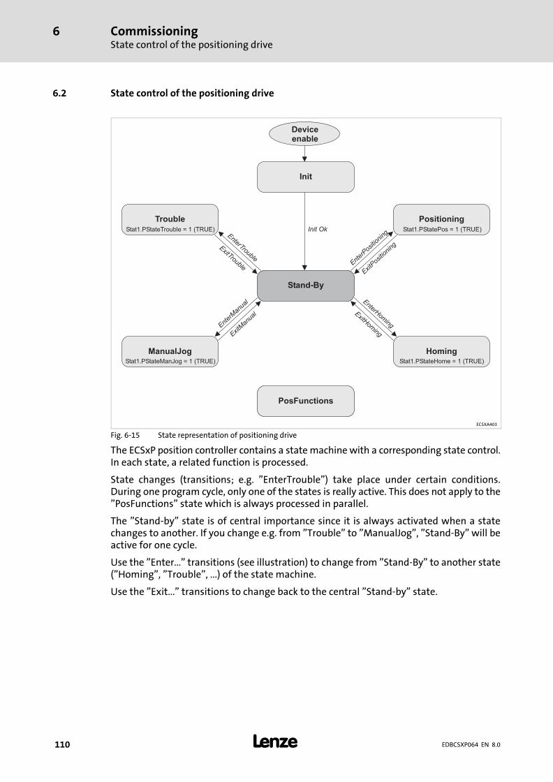
CommissioningState control of the positioning drive
6
� 110 EDBCSXP064 EN 8.0
6.2 State control of the positioning drive
ExitM
anua
l
Enter
Man
ual
EnterTrouble
ExitTrouble
EnterHom
ing
ExitHom
ing
ExitP
osition
ing
Enter
Position
ing
Deviceenable
Stand-By
Init
Init Ok
Positioning
Homing
Trouble
ManualJog
PosFunctions
Stat1.PStateTrouble = 1 (TRUE)
Stat1.PStateManJog = 1 (TRUE) Stat1.PStateHome = 1 (TRUE)
Stat1.PStatePos = 1 (TRUE)
ECSXA403
Fig. 6−15 State representation of positioning drive
The ECSxP position controller contains a state machine with a corresponding state control.In each state, a related function is processed.
State changes (transitions; e.g. "EnterTrouble") take place under certain conditions.During one program cycle, only one of the states is really active. This does not apply to the"PosFunctions" state which is always processed in parallel.
The "Stand−by" state is of central importance since it is always activated when a statechanges to another. If you change e.g. from "Trouble" to "ManualJog", "Stand−By" will beactive for one cycle.
Use the "Enter..." transitions (see illustration) to change from "Stand−By" to another state("Homing", "Trouble", ...) of the state machine.
Use the "Exit..." transitions to change back to the central "Stand−by" state.
CommissioningState control of the positioning drive
Operating states
6
� 111EDBCSXP064 EN 8.0
6.2.1 Operating states
"PosFunctions" state
These functions are permanently active, irrespective of the transitions of the state control.In the states the following "PosFunctions" are carried out:
ƒ General control functions
ƒ Calculation of the monitoring functions (software limit positions, hardware limitpositions, following errors, etc.).
The individual operating states and the conditions for state changes (transitions) aredescribed in the following.
"Stand−by" state
The following actions are executed in "stand−by":
ƒ Checking and calculation of the maximum speed indicated in C3060.
ƒ Calculation/acceptance of the monitoring limit values, e.g.:
– Following error warning tolerance
– Following error limit
– Calculation of the positioning window for the message "Target position reached"(Stat1.InTarget)
– Calculation of the time setting for the message "Dwell time elapsed"(Stat1.DwellTime)
ƒ Setting of the home position C3095/x = 101 (set home pos.)
ƒ Calculation of the internal values for homing.
"Init" state
This state is only activated once directly after the control voltage has been switched on.
The following actions are executed in "Init":
ƒ Identification of the drive hardware and firmware.
ƒ Identification and setting of the feedback systems for speed and position detection.
ƒ Checking of the home position if multi−turn absolute value encoders/resolvers areused as absolute value encoders.
ƒ Calculation of the internal values for the positioning control.
"Trouble" state
This state is activated when the operating system of the drive or the application programdetects a fault.
The following actions are executed in "Trouble":
ƒ Current fault display.
ƒ Enabling the reset mechanism for fault states.

CommissioningState control of the positioning driveOperating states
6
� 112 EDBCSXP064 EN 8.0
"ManualJog" state
This state enables manual traversing of the drive system (manual jog/inching mode)
The following actions are executed in "ManualJog":
ƒ Creation of motion profiles for the function "ManualJog" (manual control).
ƒ Evaluation of the hardware limit switches during manual jog.
ƒ Retracting from hardware limit switches.
"Homing" state
This state enables setting or automatic search of the home position.
The following actions are executed in "Homing":
ƒ Creation of motion profiles for the function "Homing" (home position search).
ƒ Evaluation of the hardware limit switches during the home position search.
"Positioning" state
This state enables the core function "Positioning of the drive system".
ƒ Positioning profiles are only executed in "Positioning".
ƒ A state change (e.g. as a result of a fault or initiated by the user) leads to animmediate quick stop (QSP) of the drive system.
In the "positioning" state the following motion profiles for positioning are created:
ƒ Point−to−point positioning
ƒ Touch probe positioning
ƒ Override positioning
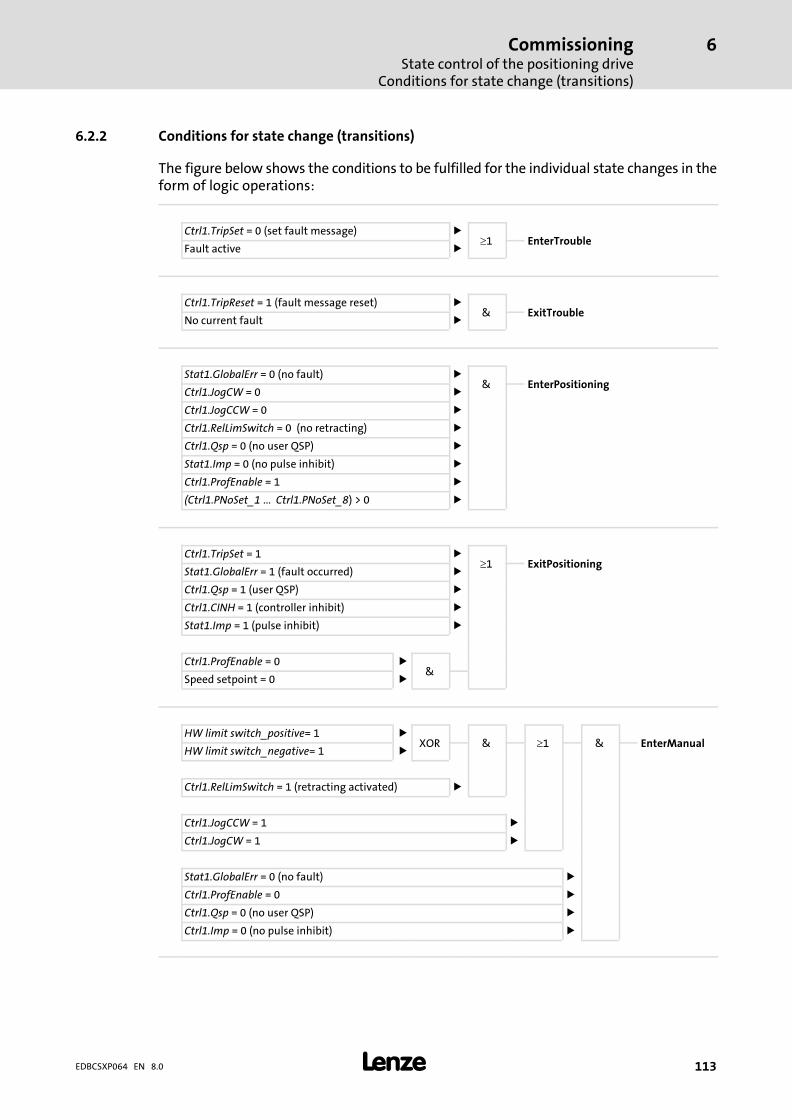
CommissioningState control of the positioning drive
Conditions for state change (transitions)
6
� 113EDBCSXP064 EN 8.0
6.2.2 Conditions for state change (transitions)
The figure below shows the conditions to be fulfilled for the individual state changes in theform of logic operations:
Ctrl1.TripSet = 0 (set fault message) ��1 EnterTrouble
Fault active �
Ctrl1.TripReset = 1 (fault message reset) �& ExitTrouble
No current fault �
Stat1.GlobalErr = 0 (no fault) �& EnterPositioning
Ctrl1.JogCW = 0 �
Ctrl1.JogCCW = 0 �
Ctrl1.RelLimSwitch = 0 (no retracting) �
Ctrl1.Qsp = 0 (no user QSP) �
Stat1.Imp = 0 (no pulse inhibit) �
Ctrl1.ProfEnable = 1 �
(Ctrl1.PNoSet_1 ... Ctrl1.PNoSet_8) > 0 �
Ctrl1.TripSet = 1 ��1 ExitPositioning
Stat1.GlobalErr = 1 (fault occurred) �
Ctrl1.Qsp = 1 (user QSP) �
Ctrl1.CINH = 1 (controller inhibit) �
Stat1.Imp = 1 (pulse inhibit) �
Ctrl1.ProfEnable = 0 �&
Speed setpoint = 0 �
HW limit switch_positive= 1 �XOR & �1 & EnterManual
HW limit switch_negative= 1 �
Ctrl1.RelLimSwitch = 1 (retracting activated) �
Ctrl1.JogCCW = 1 �
Ctrl1.JogCW = 1 �
Stat1.GlobalErr = 0 (no fault) �
Ctrl1.ProfEnable = 0 �
Ctrl1.Qsp = 0 (no user QSP) �
Ctrl1.Imp = 0 (no pulse inhibit) �
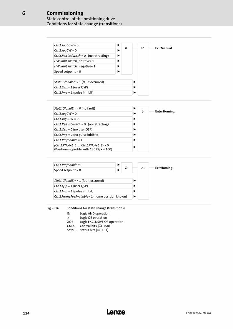
CommissioningState control of the positioning driveConditions for state change (transitions)
6
� 114 EDBCSXP064 EN 8.0
Ctrl1.JogCCW = 0 �& �1 ExitManual
Ctrl1.JogCW = 0 �
Ctrl1.RelLimSwitch = 0 (no retracting) �
HW limit switch_positive= 1 �
HW limit switch_negative= 1 �
Speed setpoint = 0 �
Stat1.GlobalErr = 1 (fault occurred) �
Ctrl1.Qsp = 1 (user QSP) �
Ctrl1.Imp = 1 (pulse inhibit) �
Stat1.GlobalErr = 0 (no fault) �& EnterHoming
Ctrl1.JogCW = 0 �
Ctrl1.JogCCW = 0 �
Ctrl1.RelLimSwitch = 0 (no retracting) �
Ctrl1.Qsp = 0 (no user QSP) �
Ctrl1.Imp = 0 (no pulse inhibit) �
Ctrl1.ProfEnable = 1 �
(Ctrl1.PNoSet_1 ... Ctrl1.PNoSet_8) > 0(Positioning profile with C3095/x = 100)
�
Ctrl1.ProfEnable = 0 �& �1 ExitHoming
Speed setpoint = 0 �
Stat1.GlobalErr = 1 (fault occurred) �
Ctrl1.Qsp = 1 (user QSP) �
Ctrl1.Imp = 1 (pulse inhibit) �
Ctrl1.HomePosAvailable= 1 (home position known) �
Fig. 6−16 Conditions for state change (transitions)
& Logic AND operation� Logic OR operationXOR Logic EXCLUSIVE OR operationCtrl1... Control bits (� 158)Stat1... Status bits (� 161)
CommissioningBefore you start
6
� 115EDBCSXP064 EN 8.0
6.3 Before you start
� Note!
ƒ The use of a Lenze motor is assumed in this description of thecommissioning steps. For details on the operation with other motors see� 244.
ƒ The operation with the Lenze parameter setting and operating program"Global Drive Control (GDC)" is taken as a basis. The parameters aredisplayed in the online mode, i.e. GDC can directly access the codes of theaxis module.
Prior to initial switch−on of the drive system, check the wiring for completeness,short−circuit, and earth fault:
ƒ Power connection:
– Polarity of the DC−bus voltage supply via terminals +UG, −UG
ƒ Motor connection:
– In−phase connection to the motor (direction of rotation)
ƒ Wiring of "safe torque off" (formerly "safe standstill")
ƒ Feedback system
ƒ Control terminals:
– Wiring adjusted to the signal assignment of the control terminals.

CommissioningCommissioning steps (overview)
6
� 116 EDBCSXP064 EN 8.0
6.4 Commissioning steps (overview)
Start
Carry out basicsettings(� 117)
Operation with continuous positioningaxis
Operation with linear positioning axis
ECSXA452 ECSXA451
Set manual jog(inching mode)
(� 121)
Set manual jog(inching mode)
(� 121)
Set homing(� 122)
Set positioningprofile with
relative positioningin the continuousmeasuring system
(� 123)
Set positioningprofile with
absolutepositioning
(� 123)
Configurecontrol interface
(� 226)
Optimise drivebehaviour(� 252)
� Save parameters in the drive withC0003 = 1.
� Save parameter set with GDC in theparameter set file.
End

CommissioningCommissioning steps (overview)
Basic settings with GDC
6
� 117EDBCSXP064 EN 8.0
6.4.1 Basic settings with GDC
� Note!
ƒ The settings are required for operation with a linear or continuouspositioning axis.
ƒ Comply with the commissioning steps in the given order.
Setting Brief description Detailedinformation
Preconditions � Mains is switched off. (Green LED is dark, red LED isblinking)
� Controller inhibit is active.– Press the <F9> key in GDC.– X6/SI1 orX6/SI2 must be open (LOW).– Control bit Ctrl1.Rsp = 1
1. Switch on low−voltage supply(24 V DC).
2. Connect PC/laptop (withinstalled GDC parametersetting program) tocontroller.
Connection to X14 (system bus (CAN)) with PC system busadapter EMF2177IB.
� 259
3. Start GDC and select thedevice to be set.
Select device:Change to the online mode via the GDC toolbar with the<F4> key and select "Searching for drives" using the <F2>key. The drive is identified and the parameter menu is opened.
GDC onlinehelp
4. Load Lenze setting. � Not required for initial commissioning of the axis module.� Only recommended if the Lenze setting is unclear.
� 125
5. Set communicationparameters according theinterface used.
Comm. parameters − CAN interface:� CAN node address (via DIP switch or C0350/C2450)� Baud rate (via DIP switch or C0351/C2451)� C0356 (CAN boot up/cycle time)� C1120 = 1 (sync connection via MotionBus (CAN))� C1121 (synchronisation cycle [in ms])
� 266
� 274� 278
Comm. parameters − AIF interface:Please also read the documentation for the Lenzecommunication module used!
AIF: Electrical shaft via EtherCAT with PLC as electrical shaftmaster (EMF2192IB)� C1120 = 2 (synchronisation via terminal X6/DI1)� C1121 (synchronisation cycle [in ms])� The synchronisation cycle set under C1121 must be set
the same as the transmission cycle of the sync telegrams.
� 224
6. Set mains data. Set the following codes in the GDC parameter menu underShort setup � Mains:� C0173 (voltage thresholds)� C0175 (function of the charge relay)
– For operation with the power supply module ECSxE setC0175 = 3.
� 126
7. Enter motor data. Lenze motors:Use the GDC motor assistant.
� 128
Motors from other manufacturers:Set the codes in the GDC parameter menu underMotor/feedback systems � Motor setting.
� 244
8. Configure holding brake. � Not required if a holding brake is not available;otherwise
� Set C4023 (speed threshold) > 0 (e.g. 1 %) to apply theholding brake.
� 130

CommissioningCommissioning steps (overview)Basic settings with GDC
6
� 118 EDBCSXP064 EN 8.0
Detailedinformation
Brief descriptionSetting
9. Set feedback system. � Set Lenze motors with resolvers (standard) in the GDCparameter menu under Short setup � Feedback system.
� Set other resolvers and encoders in the GDC parametermenu under Motor/feedback systems � Feedbacksystem.
� 132
10. Select operating mode"Control via code C4040".
Set C4010 = 3 in the GDC parameter menu under Shortsetup � Control/operating mode.
� 226
11. A Set signal assignment ofthe digital inputs.
Set C4011 in the GDC parameter menu under Short setup �Digital inputs/outputs:� Operation with continuous positioning axis: C4011 = 5� Operation with linear positioning axis: C4011 = 0
� 168
B Set the polarity of thedigital inputs and outputs.
� Set IC0114/x (polarity X6/DI1 ... DI4) in the GDCparameter menu under Terminals I/O � Digital inputs.
� Set C0118/1 (polarity X6/DO1) in the GDC parametermenu under Terminals I/O � Digital outputs.
� 172
12. Enter machine parameters. Set the following codes in the GDC parameter menu inPositioning/E−Shaft � Machine parameters:� C1202 (gearbox ratio numerator: number of teeth on the
machine side or speed on the motor side)� C1203 (gearbox ratio denominator: number of teeth on
the motor side or speed on the machine side)� C1204 (feed constant)� C1240 (max. speed of the machine)� C1250 (max. acceleration of the machine)� C3031 (following error limit)� C3040 (positive software limit position)� C3041 (negative software limit position)� C0105 (quick stop deceleration time)
� 165
13. Switch on the mains. � Green LED is blinking, red LED is off:– Controller is ready for operation.
� Green LED is off, red LED is blinking:– An error has occurred. Eliminate the error before you
continue commissioning.
14. Carry out a positioning profilewith the positioning profilemode "Set reference".
Only required....� in the case of initial commissioning of an absolute value
encoder (multi−turn/single−turn);� after the replacement of an encoder, controller, or motor;� if modifications regarding the mechanics are carried out.
� 119
The basic settings are completed now.
Proceed as follows:
ƒ Set Manual jog (inching mode) (� 121).

CommissioningCommissioning steps (overview)
Set reference
6
� 119EDBCSXP064 EN 8.0
6.4.2 Set reference
� Note!
Setting the reference (homing) is required ...
ƒ in the case of initial commissioning of an absolute value encoder(multi−turn/single−turn);
ƒ after the replacement of an encoder, controller, or motor;
ƒ if modifications regarding the mechanics are carried out.
ƒ When homing is carried out, the current position is defined as zero position (homeposition).
ƒ Reference setting can be carried out in all connectable encoder systems.
ƒ For setting the reference, the homing status "Reference known" (HomePosAvailable)has to be reset (C4045/bit 13 = 0).
If "Reference know" has already been set (C4045/Bit 13 = 1), first the "ResetHomePosAvailable" profile function has to be executed (C3095/x = 102) to reset thestatus.
Set reference for absolute value encoders (multi−turn)
Reference setting does not influence the internal value of the absolute value encoder. TheECSxP axis module "remembers" the zero position (home position) via correspondingoffset variables with regard to the overflow point of the absolute value encoder. The axismodule is not limited to the 4096 displayable revolutions in the absolute value encoder.Thus the maximum display range (like for the resolver) is provided to the module. Thecondition for this is that the absolute value encoder in the switched−off state is not movedmore than ± 2048 revolutions.
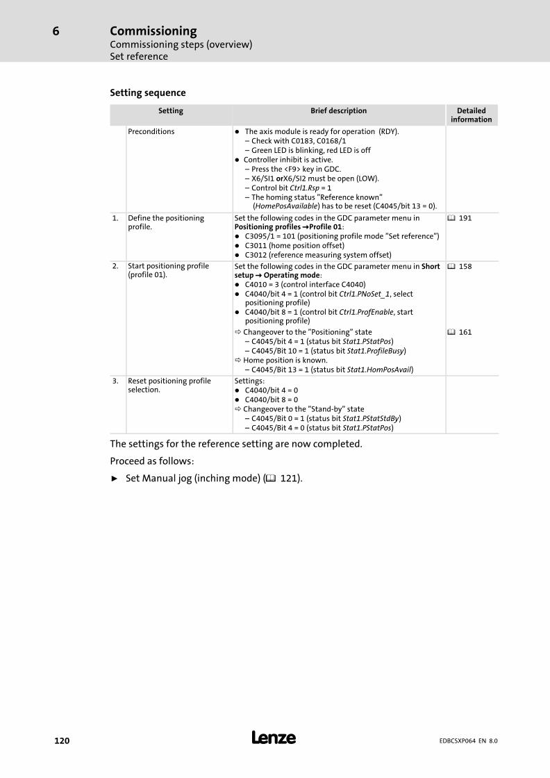
CommissioningCommissioning steps (overview)Set reference
6
� 120 EDBCSXP064 EN 8.0
Setting sequence
Setting Brief description Detailedinformation
Preconditions � The axis module is ready for operation (RDY).– Check with C0183, C0168/1– Green LED is blinking, red LED is off
� Controller inhibit is active.– Press the <F9> key in GDC.– X6/SI1 orX6/SI2 must be open (LOW).– Control bit Ctrl1.Rsp = 1– The homing status "Reference known"
(HomePosAvailable) has to be reset (C4045/bit 13 = 0).
1. Define the positioningprofile.
Set the following codes in the GDC parameter menu inPositioning profiles �Profile 01:� C3095/1 = 101 (positioning profile mode "Set reference")� C3011 (home position offset)� C3012 (reference measuring system offset)
� 191
2. Start positioning profile(profile 01).
Set the following codes in the GDC parameter menu in Shortsetup � Operating mode:� C4010 = 3 (control interface C4040)� C4040/bit 4 = 1 (control bit Ctrl1.PNoSet_1, select
positioning profile)� C4040/bit 8 = 1 (control bit Ctrl1.ProfEnable, start
positioning profile)
� 158
Changeover to the "Positioning" state– C4045/bit 4 = 1 (status bit Stat1.PStatPos)– C4045/Bit 10 = 1 (status bit Stat1.ProfileBusy)
Home position is known.– C4045/Bit 13 = 1 (status bit Stat1.HomPosAvail)
� 161
3. Reset positioning profileselection.
Settings:� C4040/bit 4 = 0� C4040/bit 8 = 0 Changeover to the "Stand−by" state
– C4045/Bit 0 = 1 (status bit Stat1.PStatStdBy)– C4045/Bit 4 = 0 (status bit Stat1.PStatPos)
The settings for the reference setting are now completed.
Proceed as follows:
ƒ Set Manual jog (inching mode) (� 121).

CommissioningCommissioning steps (overview)
Setting of manual jog (inching mode)
6
� 121EDBCSXP064 EN 8.0
6.4.3 Setting of manual jog (inching mode)
� Stop!
Machine parts can be damaged or destroyed!
The drive can travel into a mechanical limit during manual jog if
ƒ no reference is known (status bit Stat1.HomePosAvailable = 0, � 161).
ƒ no software limit positions are set ( 237).
A manual jog requires the following commissioning steps:
Setting Brief description Detailedinformation
1. Set parameters for themanual control.
Set the following codes in the GDC parameter menu inPositioning�� Manual jog:� C3020 (traversing speed)� C3021 (acceleration)� C3022 (deceleration)
� 173
2. Save parameter set. Set C0003 = 1.
3. Enable controller. � Press the <F8> key in the GDC.� Green LED is lit continuously if X6/SI1 = HIGH,
X6/SI2 = HIGH, and the controller has been enabled viathe master control (PLC).
� Green LED is blinking if X6/SI1 = HIGH and X6/SI2 = HIGH.(No enable via master control!)
� 241
4. Set the direction of rotationfor manual control.
Set the following codes in the GDC parameter menu in Shortsetup � Operating mode:� C4010 = 3 (control interface C4040)� Control bits for CCW rotation (JogCCW):
– C4040/bit 12 = 1– C4040/bit 13 = 0 Changeover to "ManualJog"state– C4045/bit 2 = 1 (status bit Stat1.PStatManJog)
� Control bits for CW rotation (JogCW):– C4040/bit 12 = 0– C4040/bit 13 = 1 Changeover to "ManualJog"state– C4045/bit 2 = 1 (status bit Stat1.PStatManJog)
� Control bits for manual jog stop:– C4040/bit 12 = 0– C4040/bit 13 = 0 Changeover to the "Stand−by" state– C4045/Bit 0 = 1 (status bit Stat1.PStatStdBy)
Note:In the case of C4040/bit 12 = 1 and bit 13 = 1, manual jog isinterrupted until one of the two bits is set to "0". The stateremains unchanged.
� 158� 161
The motor rotates in the direction selected.
The settings for manual jog are now completed.
Proceed as follows:
ƒ Set homing (� 122) when operating with a linear positioning axis
or
ƒ Set relative continuous positioning (� 123) when operating with a continuouspositioning axis
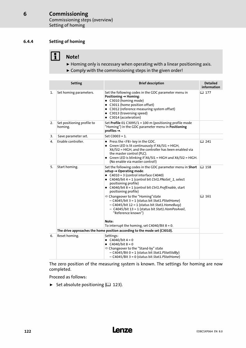
CommissioningCommissioning steps (overview)Setting of homing
6
� 122 EDBCSXP064 EN 8.0
6.4.4 Setting of homing
� Note!
ƒ Homing only is necessary when operating with a linear positioning axis.
ƒ Comply with the commissioning steps in the given order!
Setting Brief description Detailedinformation
1. Set homing parameters. Set the following codes in the GDC parameter menu inPositioning � Homing:� C3010 (homing mode)� C3011 (home position offset)� C3012 (reference measuring system offset)� C3013 (traversing speed)� C3014 (acceleration)
� 177
2. Set positioning profile tohoming.
Set Profile 01 C3095/1 = 100 m (positioning profile mode"Homing") in the GDC parameter menu in Positioningprofiles �.
3. Save parameter set. Set C0003 = 1.
4. Enable controller. � Press the <F8> key in the GDC.� Green LED is lit continuously if X6/SI1 = HIGH,
X6/SI2 = HIGH, and the controller has been enabled viathe master control (PLC).
� Green LED is blinking if X6/SI1 = HIGH and X6/SI2 = HIGH.(No enable via master control!)
� 241
5. Start homing. Set the following codes in the GDC parameter menu in Shortsetup � Operating mode:� C4010 = 3 (control interface C4040)� C4040/bit 4 = 1 (control bit Ctrl1.PNoSet_1, select
positioning profile)� C4040/bit 8 = 1 (control bit Ctrl1.ProfEnable, start
positioning profile)
� 158
Changeover to the "Homing"state– C4045/bit 3 = 1 (status bit Stat1.PStatHome)– C4045/bit 12 = 1 (status bit Stat1.HomeBusy)– C4045/bit 13 = 1 (status bit Stat1.HomPosAvail,
"Reference known")
Note:To interrupt the homing, set C4040/Bit 8 = 0.
� 161
The drive approaches the home position according to the mode set (C3010).
6. Reset homing. Settings:� C4040/bit 4 = 0� C4040/bit 8 = 0 Changeover to the "Stand−by" state
– C4045/Bit 0 = 1 (status bit Stat1.PStatStdBy)– C4045/Bit 3 = 0 (status bit Stat1.PStatHome)
The zero position of the measuring system is known. The settings for homing are nowcompleted.
Proceed as follows:
ƒ Set absolute positioning (� 123).

CommissioningCommissioning steps (overview)
Setting absolute positioning/relative continuous positioning
6
� 123EDBCSXP064 EN 8.0
6.4.5 Setting absolute positioning/relative continuous positioning
� Note!
ƒ Absolute positioning is required for operation with a linear positioning axis.
ƒ Relative positioning in the continuous measuring system is required foroperation with a continuous positioning axis.
ƒ Comply with the commissioning steps in the given order!
Operation with a continuous positioning axis Operation with a linear positioning axis
1. Definition of positioning profile with relativepositioning in the continuous measuring system.(� 191)
Set the following codes in the GDC parameter menuin Positioning profiles � Profile 02:� C3095/2 = 1 (positioning profile mode "modulo
pos.")
Definition of positioning profile with absolutepositioning. (� 191)
Set the following codes in the GDC parameter menuin Positioning profiles ��Profile 02:� C3095/2 = 0 (positioning profile mode "absolute
pos.")
� C3100/2 (position for positioning profile 2)� C3200/2 (speed for positioning profile 2)� C3300/2 (acceleration for positioning profile 2)� C3400/2 (deceleration for positioning profile 2)
2. Enable controller. (�� 241)� Press the <F8> key in the GDC.� Green LED is lit continuously if X6/SI1 = HIGH, X6/SI2 = HIGH, and the controller has been enabled via
the master control (PLC).� Green LED is blinking if X6/SI1 = HIGH and X6/SI2 = HIGH. (No enable via master control!)
3. Start positioning profile (profile 02).
Set the following codes in the GDC parameter menu in Short setup � Operating mode:� C4010 = 3 (control interface C4040)� C4040/Bit 5 = 1 (control bit Ctrl1.PNoSet_2, select positioning profile)� C4040/bit 8 = 1 (control bit Ctrl1.ProfEnable, start positioning profile) Changeover to the "Positioning" state
– C4045/bit 4 = 1 (status bit Stat1.PStatPos)– C4045/Bit 10 = 1 (status bit Stat1.ProfileBusy)
(Control bits see � 158, status bits see� 161)
The drive travels the relative distance specifiedunder C3100/2.
The drive approaches the absolute target positiondefined by C3100/2.
4. Reset positioning profile (profile 02).
Settings:� C4040/bit 5 = 0� C4040/bit 8 = 0 Changeover to the "Stand−by" state
– C4045/Bit 0 = 1 (status bit Stat1.PStatStdBy)– C4045/Bit 4 = 0 (status bit Stat1.PStatPos)– C4045/Bit 14 = 1 (status bit Stat1.InTarget)– C4045/Bit 15 = 1 (status bit Stat1.DwellTime)
Note:To traverse a positioning profile with relativepositioning in the continuous measuring systemagain, repeat steps 3. and 4.
Note:To retravel a positioning profile with absolutepositioning,� change the value in C3100/2 (see step 1.);� then continue with steps 3. and 4.

CommissioningCommissioning steps (overview)Setting absolute positioning/relative continuous positioning
6
� 124 EDBCSXP064 EN 8.0
Operation with a linear positioning axisOperation with a continuous positioning axis
5. Inhibit controller.� Press the <F9> key in GDC.� X6/SI1 orX6/SI2 must be open (LOW).� C4040/bit 9 = 1 (Ctrl1.Rsp)
6. Set the operating mode required for the application via C4010 in the GDC parameter menu under Shortsetup � Operating mode. (� 226)
The settings for travel with absolute positioning or relative positioning in the continuousmeasuring system are completed.
Proceed as follows:
ƒ Save parameters in the controller with C0003 = 1.
ƒ Save parameter set with GDC in the parameter set file.
ƒ Enable controller (� 252).
ƒ Optimise drive behaviour (� 252).

CommissioningLoading the Lenze setting
6
� 125EDBCSXP064 EN 8.0
6.5 Loading the Lenze setting
� Note!
When loading the Lenze setting, all parameters are reset to the basic settingdefined by Lenze. Settings that have been adjusted before get lost during thisprocess!
In GDC, you can find the parameters and codes to be set in the parameter menu in�Load /Save / PLC.
ECSXA312
Fig. 6−17 GDC view: Parameter set management
Setting sequence
1. Stop the PLC program: C2108 = 2
2. Load the Lenze setting: C0002 = 0
3. Continue with 3.1 or 3.2.
3.1 The 24−V supply voltage can be switched.
A Switch off and on again the 24 V−supply voltage.
B Plug the keypad XT (EMZ9371BC) onto the AIF interface (X1).
3.2 The 24−V supply voltage cannot be switched.
A Plug the keypad XT (EMZ9371BC) onto the AIF interface (X1).
B Reset the PLC: C2108 = 3
4. Continue with basic settings from point 5 of the table on � 117.
5. Automatic start of the PLC program after power−up: C2104 = 1
6. Start the PLC program: C2108 = 1
7. Save parameter set: C0003 = 1
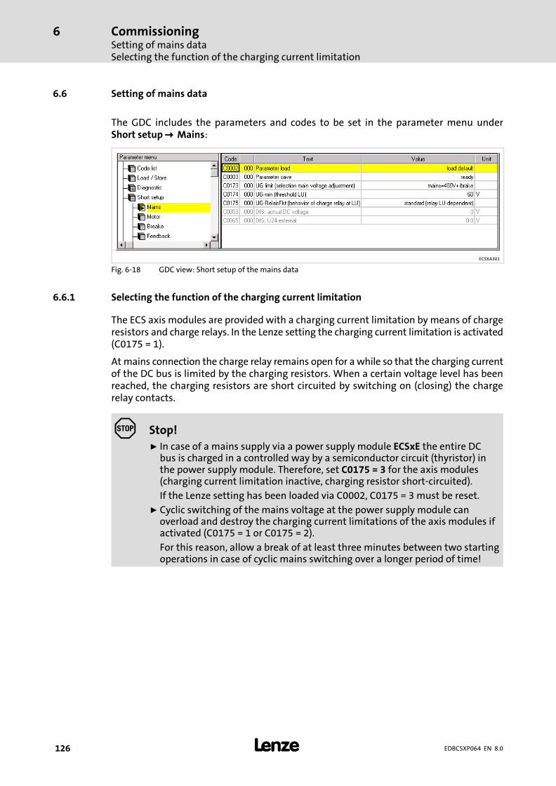
CommissioningSetting of mains dataSelecting the function of the charging current limitation
6
� 126 EDBCSXP064 EN 8.0
6.6 Setting of mains data
The GDC includes the parameters and codes to be set in the parameter menu underShort setup ��Mains:
ECSXA301
Fig. 6−18 GDC view: Short setup of the mains data
6.6.1 Selecting the function of the charging current limitation
The ECS axis modules are provided with a charging current limitation by means of chargeresistors and charge relays. In the Lenze setting the charging current limitation is activated(C0175 = 1).
At mains connection the charge relay remains open for a while so that the charging currentof the DC bus is limited by the charging resistors. When a certain voltage level has beenreached, the charging resistors are short circuited by switching on (closing) the chargerelay contacts.
� Stop!
ƒ In case of a mains supply via a power supply module ECSxE the entire DCbus is charged in a controlled way by a semiconductor circuit (thyristor) inthe power supply module. Therefore, set C0175 = 3 for the axis modules(charging current limitation inactive, charging resistor short−circuited).
If the Lenze setting has been loaded via C0002, C0175 = 3 must be reset.
ƒ Cyclic switching of the mains voltage at the power supply module canoverload and destroy the charging current limitations of the axis modules ifactivated (C0175 = 1 or C0175 = 2).
For this reason, allow a break of at least three minutes between two startingoperations in case of cyclic mains switching over a longer period of time!
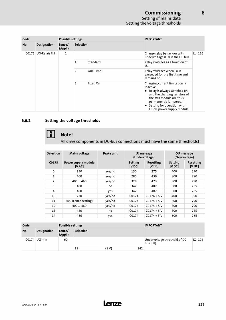
CommissioningSetting of mains data
Setting the voltage thresholds
6
� 127EDBCSXP064 EN 8.0
Code Possible settings IMPORTANT
No. Designation Lenze/{Appl.}
Selection
C0175 UG−Relais Fkt 1 Charge relay behaviour withundervoltage (LU) in the DC bus.
� 126
1 Standard Relay switches as a function ofLU.
2 One Time Relay switches when LU isexceeded for the first time andremains on.
3 Fixed On Charging current limitation isinactive.� Relay is always switched on
and the charging resistors ofthe axis module are thuspermanently jumpered.
� Setting for operation withECSxE power supply module.
6.6.2 Setting the voltage thresholds
� Note!
All drive components in DC−bus connections must have the same thresholds!
Selection Mains voltage Brake unit LU message(Undervoltage)
OU message(Overvoltage)
C0173 Power supply module[V AC]
Setting[V DC]
Resetting[V DC]
Setting[V DC]
Resetting[V DC]
0 230 yes/no 130 275 400 390
1 400 yes/no 285 430 800 790
2 400 ... 460 yes/no 328 473 800 790
3 480 no 342 487 800 785
4 480 yes 342 487 800 785
10 230 yes/no C0174 C0174 + 5 V 400 390
11 400 (Lenze setting) yes/no C0174 C0174 + 5 V 800 790
12 400 ... 460 yes/no C0174 C0174 + 5 V 800 790
13 480 no C0174 C0174 + 5 V 800 785
14 480 yes C0174 C0174 + 5 V 800 785
Code Possible settings IMPORTANT
No. Designation Lenze/{Appl.}
Selection
C0174 UG min 60 Undervoltage threshold of DCbus (LU)
� 126
15 {1 V} 342
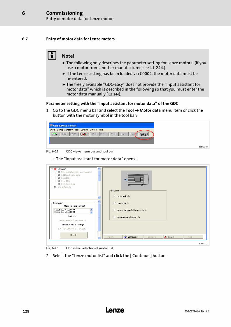
CommissioningEntry of motor data for Lenze motors
6
� 128 EDBCSXP064 EN 8.0
6.7 Entry of motor data for Lenze motors
� Note!
ƒ The following only describes the parameter setting for Lenze motors! (If youuse a motor from another manufacturer, see � 244.)
ƒ If the Lenze setting has been loaded via C0002, the motor data must bere−entered.
ƒ The freely available "GDC−Easy" does not provide the "Input assistant formotor data" which is described in the following so that you must enter themotor data manually ( � 244).
Parameter setting with the "Input assistant for motor data" of the GDC
1. Go to the GDC menu bar and select the Tool � Motor data menu item or click thebutton with the motor symbol in the tool bar:
ECSXA300
Fig. 6−19 GDC view: menu bar and tool bar
– The "Input assistant for motor data" opens:
ECSXA311
Fig. 6−20 GDC view: Selection of motor list
2. Select the "Lenze motor list" and click the [ Continue ] button.

CommissioningEntry of motor data for Lenze motors
6
� 129EDBCSXP064 EN 8.0
ECSXA302
Fig. 6−21 GDC view: Motor selection
3. Select the connected motor from the list (see motor nameplate).
– The corresponding motor data is displayed in the "Motor data" fields on the right.
4. Click the [ Complete ] button.
– The data is transferred to the controller. This process can take a few seconds and isconfirmed by a message after being completed.
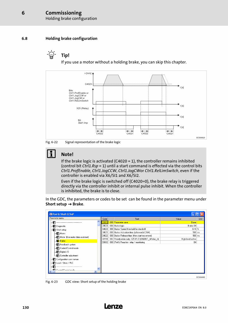
CommissioningHolding brake configuration
6
� 130 EDBCSXP064 EN 8.0
6.8 Holding brake configuration
� Tip!
If you use a motor without a holding brake, you can skip this chapter.
v [m/s]
Bits:or
oror
Ctrl1.ProfEnableCtrl1.JogCCWCtrl1.JogCWCtrl1.RelLimSwitch
X25 (Relay)
Bit:Stat1.Imp
C4023
C4021 C4021C4022C4022
t [s]
t [s]
t [s]
t [s]
ECSXA410
Fig. 6−22 Signal representation of the brake logic
� Note!
If the brake logic is activated (C4020 = 1), the controller remains inhibited(control bit Ctrl1.Rsp = 1) until a start command is effected via the control bitsCtrl1.ProfEnable, Ctrl1.JogCCW, Ctrl1.JogCWor Ctrl1.RelLimSwitch, even if thecontroller is enabled via X6/SI1 and X6/SI2.
Even if the brake logic is switched off (C4020=0), the brake relay is triggereddirectly via the controller inhibit or internal pulse inhibit. When the controlleris inhibited, the brake is to close.
In the GDC, the parameters or codes to be set can be found in the parameter menu underShort setup�� Brake.
ECSXA440
Fig. 6−23 GDC view: Short setup of the holding brake
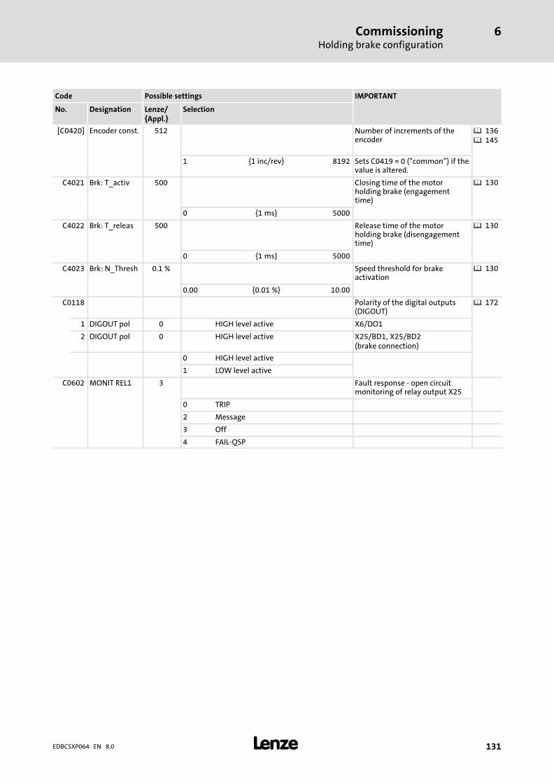
CommissioningHolding brake configuration
6
� 131EDBCSXP064 EN 8.0
Code Possible settings IMPORTANT
No. Designation Lenze/{Appl.}
Selection
[C0420] Encoder const. 512 Number of increments of theencoder
� 136� 145
1 {1 inc/rev} 8192 Sets C0419 = 0 ("common") if thevalue is altered.
C4021 Brk: T_activ 500 Closing time of the motorholding brake (engagementtime)
� 130
0 {1 ms} 5000
C4022 Brk: T_releas 500 Release time of the motorholding brake (disengagementtime)
� 130
0 {1 ms} 5000
C4023 Brk: N_Thresh 0.1 % Speed threshold for brakeactivation
� 130
0.00 {0.01 %} 10.00
C0118 Polarity of the digital outputs(DIGOUT)
� 172
1 DIGOUT pol 0 HIGH level active X6/DO1
2 DIGOUT pol 0 HIGH level active X25/BD1, X25/BD2(brake connection)
0 HIGH level active
1 LOW level active
C0602 MONIT REL1 3 Fault response − open circuitmonitoring of relay output X25
0 TRIP
2 Message
3 Off
4 FAIL−QSP
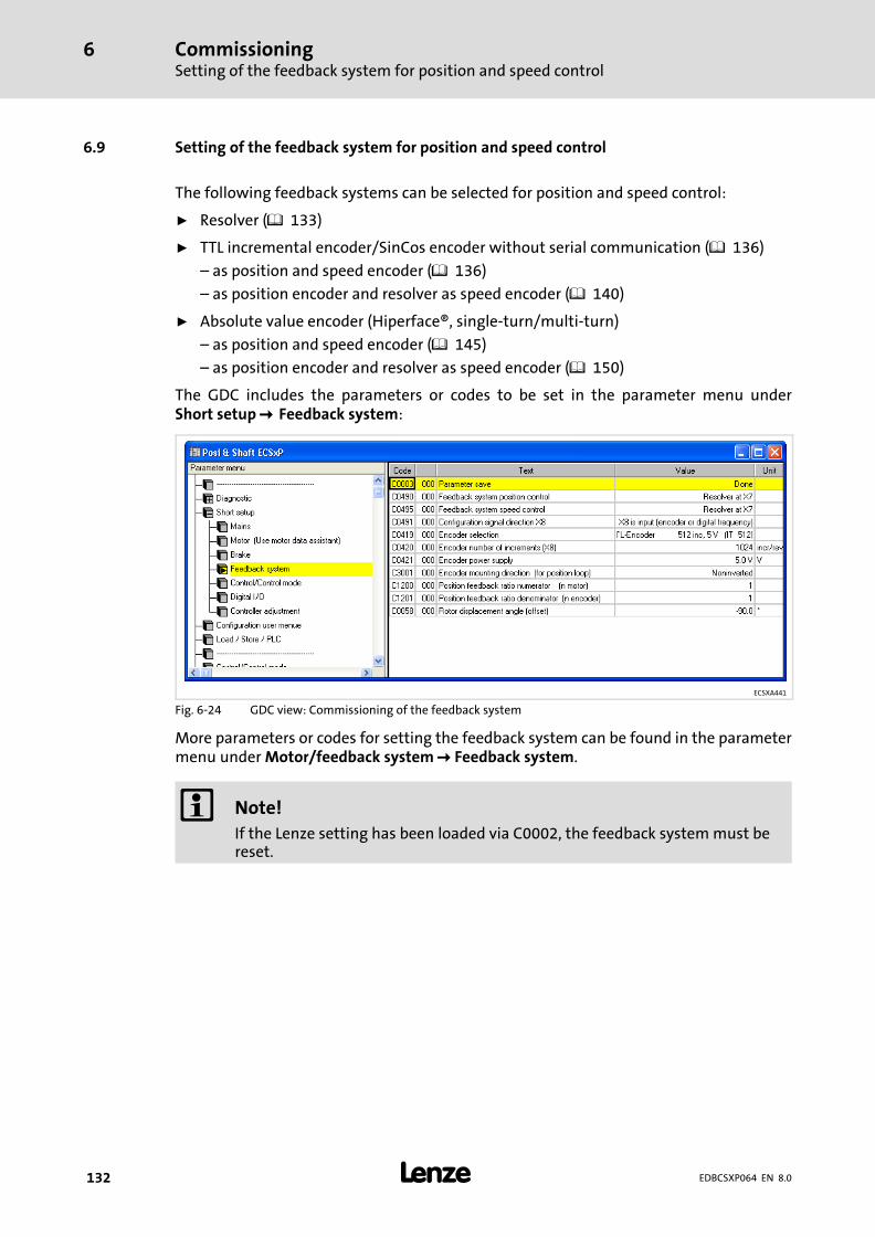
CommissioningSetting of the feedback system for position and speed control
6
� 132 EDBCSXP064 EN 8.0
6.9 Setting of the feedback system for position and speed control
The following feedback systems can be selected for position and speed control:
ƒ Resolver ( 133)
ƒ TTL incremental encoder/SinCos encoder without serial communication ( 136)
– as position and speed encoder ( 136)
– as position encoder and resolver as speed encoder ( 140)
ƒ Absolute value encoder (Hiperface®, single−turn/multi−turn)
– as position and speed encoder ( 145)
– as position encoder and resolver as speed encoder ( 150)
The GDC includes the parameters or codes to be set in the parameter menu underShort setup ��Feedback system:
ECSXA441
Fig. 6−24 GDC view: Commissioning of the feedback system
More parameters or codes for setting the feedback system can be found in the parametermenu under Motor/feedback system � Feedback system.
� Note!
If the Lenze setting has been loaded via C0002, the feedback system must bereset.

CommissioningSetting of the feedback system for position and speed control
Resolver as position and speed encoder
6
� 133EDBCSXP064 EN 8.0
6.9.1 Resolver as position and speed encoder
If a resolver is connected to X7 and used as a position and speed encoder, no settings arenecessary.
Lenze setting:
ƒ Resolver as position encoder: C0490 = 0
ƒ Resolver as speed encoder: C0495 = 0
Codes for feedback system selection
Code Possible settings IMPORTANT
No. Designation Lenze/{Appl.}
Selection
[C0490] Feedback pos 0 Selection of feedback system forpositioning control
� 132
0 Resolver at X7 Standard setting
1 TTL encoder at X8 � Sets C0419 = 0 ("Common") ifa different encoder type asunder C0419 is set here.
2 SinCos encoder at X8
3 Absolute value encoder (single−turn) atX8
4 Absolute value encoder (multi−turn) atX8
[C0495] Feedback n 0 Selection of feedback system forspeed control
� 132
0 Resolver at X7 Standard setting
1 TTL encoder at X8 � Sets C0419 = 0 ("Common") ifa different encoder type asunder C0419 is set here.
2 SinCos encoder at X8
3 Absolute value encoder (single−turn) atX8
4 Absolute value encoder (multi−turn) atX8
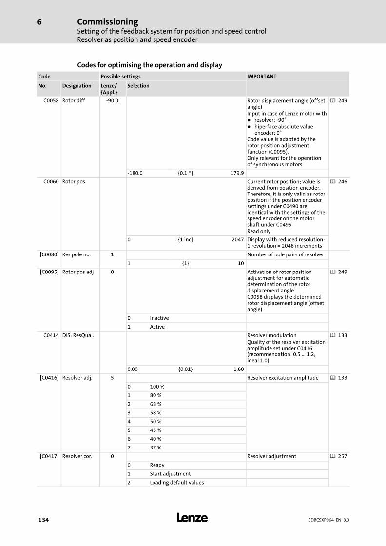
CommissioningSetting of the feedback system for position and speed controlResolver as position and speed encoder
6
� 134 EDBCSXP064 EN 8.0
Codes for optimising the operation and display
Code Possible settings IMPORTANT
No. Designation Lenze/{Appl.}
Selection
C0058 Rotor diff −90.0 Rotor displacement angle (offsetangle)Input in case of Lenze motor with� resolver: −90°� hiperface absolute value
encoder: 0°Code value is adapted by therotor position adjustmentfunction (C0095).Only relevant for the operationof synchronous motors.
� 249
−180.0 {0.1 �} 179.9
C0060 Rotor pos Current rotor position; value isderived from position encoder.Therefore, it is only valid as rotorposition if the position encodersettings under C0490 areidentical with the settings of thespeed encoder on the motorshaft under C0495.Read only
� 246
0 {1 inc} 2047 Display with reduced resolution:1 revolution = 2048 increments
[C0080] Res pole no. 1 Number of pole pairs of resolver
1 {1} 10
[C0095] Rotor pos adj 0 Activation of rotor positionadjustment for automaticdetermination of the rotordisplacement angle.C0058 displays the determinedrotor displacement angle (offsetangle).
� 249
0 Inactive
1 Active
C0414 DIS: ResQual. Resolver modulationQuality of the resolver excitationamplitude set under C0416(recommendation: 0.5 ... 1.2;ideal 1.0)
� 133
0.00 {0.01} 1,60
[C0416] Resolver adj. 5 Resolver excitation amplitude � 133
0 100 %
1 80 %
2 68 %
3 58 %
4 50 %
5 45 %
6 40 %
7 37 %
[C0417] Resolver cor. 0 Resolver adjustment � 257
0 Ready
1 Start adjustment
2 Loading default values

CommissioningSetting of the feedback system for position and speed control
Resolver as absolute value encoder
6
� 135EDBCSXP064 EN 8.0
6.9.2 Resolver as absolute value encoder
If the following requirements are met, a resolver (or single−turn absolute value encoder)can take over the function of a multi−turn absolute value encoder:
ƒ When the axis module is switched off, the reference is known.
ƒ Until the axis module is connected for the next time, it is ensured that the positionof the machine part does not change (e.g. by using a brake). When switched off, themotor encoder may maximally move +/− half a revolution.
ƒ C3002 = 1 (initialisation with saved actual position after power on)
At switch off, the actual position is saved fail−safe. After switch on, the actual position isre−initialised with this value. Turning the drive by maximally ± ½ revolution of the positionencoder when the axis module is switched off will be detected and considered when theactual position is initialised (loaded).
General formula for the calculation of the maximum resolver rotation when the axismodule is switched off, in particular for multi−pole resolvers (number of pole pairs > 1):
Max.�rotation� ��� 180°number_of_pole_pairs
Code Possible settings IMPORTANT
No. Designation Lenze/{Appl.}
Selection
C3002 NoChangeOfPos
0 Resolver as absolute valueencoder
� 135
0 ChangeOfPos After "mains off/on", hominghas to be carried out.The actual position is initialisedwith the value "0".
1 NoChangeOfPos The actual position value isinitialised with the positionvalue at "Mains off" and is usedfurther at "Mains on".Homing is not required.Note: With "Mains off" thefeedback system must rotate lessthan � 0.5 revolutions.
CommissioningSetting of the feedback system for position and speed controlTTL/SinCos encoder as position and speed encoder
6
� 136 EDBCSXP064 EN 8.0
6.9.3 TTL/SinCos encoder as position and speed encoder
If an incremental encoder or a SinCos encoder without serial communication is connectedto X8 and used for position and speed control, comply with the following setting sequence:
1. Select encoder for position and speed control.
– Incremental encoder (TTL encoder): C0490 and C0495 = 1
– SinCos encoder without serial communication: C0490 and C0495 = 2
If X8 has been selected as output by changing C0491, X8 will be automatically reset toinput through the encoder selection.
2. Select encoder used.
– Incremental encoder (TTL encoder): C0419 = 110 ... 113
– SinCos encoder without serial communication: C0419 = 210 ... 213
– Encoder used is not in the list: C0419 = 1 ("Common")
3. When setting C0419 = 1 ("Common") configure encoder data.
� Note!
When setting C0419 = 11x or 21x do not configure encoder data.
The encoder data (C0420, C0421, C0427) is set automatically in accordancewith the selection.
– C0420 (number of increments of the encoder)
– C0421 (encoder voltage)
– C0427 (signal type of the encoder)
4. Set the encoder mounting position.
– C3001 = 0: normal (direction of rotation CW with regard to direction of rotation ofthe motor)
– C3001 = 1: inverse (direction of rotation CCW with regard to direction of rotationof the motor)
5. Save settings with C0003 = 1.
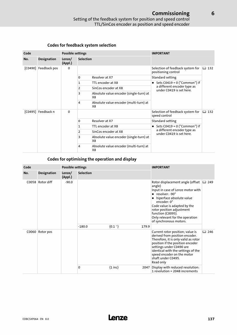
CommissioningSetting of the feedback system for position and speed control
TTL/SinCos encoder as position and speed encoder
6
� 137EDBCSXP064 EN 8.0
Codes for feedback system selection
Code Possible settings IMPORTANT
No. Designation Lenze/{Appl.}
Selection
[C0490] Feedback pos 0 Selection of feedback system forpositioning control
� 132
0 Resolver at X7 Standard setting
1 TTL encoder at X8 � Sets C0419 = 0 ("Common") ifa different encoder type asunder C0419 is set here.
2 SinCos encoder at X8
3 Absolute value encoder (single−turn) atX8
4 Absolute value encoder (multi−turn) atX8
[C0495] Feedback n 0 Selection of feedback system forspeed control
� 132
0 Resolver at X7 Standard setting
1 TTL encoder at X8 � Sets C0419 = 0 ("Common") ifa different encoder type asunder C0419 is set here.
2 SinCos encoder at X8
3 Absolute value encoder (single−turn) atX8
4 Absolute value encoder (multi−turn) atX8
Codes for optimising the operation and display
Code Possible settings IMPORTANT
No. Designation Lenze/{Appl.}
Selection
C0058 Rotor diff −90.0 Rotor displacement angle (offsetangle)Input in case of Lenze motor with� resolver: −90°� hiperface absolute value
encoder: 0°Code value is adapted by therotor position adjustmentfunction (C0095).Only relevant for the operationof synchronous motors.
� 249
−180.0 {0.1 �} 179.9
C0060 Rotor pos Current rotor position; value isderived from position encoder.Therefore, it is only valid as rotorposition if the position encodersettings under C0490 areidentical with the settings of thespeed encoder on the motorshaft under C0495.Read only
� 246
0 {1 inc} 2047 Display with reduced resolution:1 revolution = 2048 increments
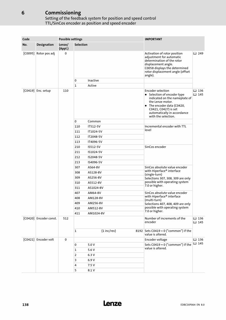
CommissioningSetting of the feedback system for position and speed controlTTL/SinCos encoder as position and speed encoder
6
� 138 EDBCSXP064 EN 8.0
IMPORTANTPossible settingsCode
SelectionLenze/{Appl.}
DesignationNo.
[C0095] Rotor pos adj 0 Activation of rotor positionadjustment for automaticdetermination of the rotordisplacement angle.C0058 displays the determinedrotor displacement angle (offsetangle).
� 249
0 Inactive
1 Active
[C0419] Enc. setup 110 Encoder selection� Selection of encoder type
indicated on the nameplate ofthe Lenze motor.
� The encoder data (C0420,C0421, C0427) is setautomatically in accordancewith the selection.
� 136� 145
0 Common
110 IT512−5V Incremental encoder with TTLlevel111 IT1024−5V
112 IT2048−5V
113 IT4096−5V
210 IS512−5V SinCos encoder
211 IS1024−5V
212 IS2048−5V
213 IS4096−5V
307 AS64−8V SinCos absolute value encoderwith Hiperface® interface(single−turn)Selections 307, 308, 309 are onlypossible with operating system7.0 or higher.
308 AS128−8V
309 AS256−8V
310 AS512−8V
311 AS1024−8V
407 AM64−8V SinCos absolute value encoderwith Hiperface® interface(multi−turn)Selections 407, 408, 409 are onlypossible with operating system7.0 or higher.
408 AM128−8V
409 AM256−8V
410 AM512−8V
411 AM1024−8V
[C0420] Encoder const. 512 Number of increments of theencoder
� 136� 145
1 {1 inc/rev} 8192 Sets C0419 = 0 ("common") if thevalue is altered.
[C0421] Encoder volt 0 Encoder voltage � 136� 1450 5.0 V Sets C0419 = 0 ("common") if the
value is altered.1 5.6 V
2 6.3 V
3 6.9 V
4 7.5 V
5 8.1 V
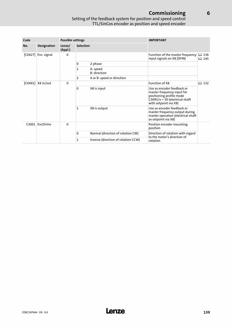
CommissioningSetting of the feedback system for position and speed control
TTL/SinCos encoder as position and speed encoder
6
� 139EDBCSXP064 EN 8.0
IMPORTANTPossible settingsCode
SelectionLenze/{Appl.}
DesignationNo.
[C0427] Enc. signal 0 Function of the master frequencyinput signals on X8 (DFIN)
� 136� 145
0 2−phase
1 A: speedB: direction
2 A or B: speed or direction
[C0491] X8 in/out 0 Function of X8 � 132
0 X8 is input Use as encoder feedback ormaster frequency input forpositioning profile modeC3095/x = 30 (electrical shaftwith setpoint via X8)
1 X8 is output Use as encoder feedback ormaster frequency output duringmaster operation (electrical shaftas setpoint via X8)
C3001 EncDirInv 0 Position encoder mountingposition
0 Normal (direction of rotation CW) Direction of rotation with regardto the motor’s direction ofrotation1 Inverse (direction of rotation CCW)
CommissioningSetting of the feedback system for position and speed controlTTL/SinCos encoder as position encoder and resolver as speed encoder
6
� 140 EDBCSXP064 EN 8.0
6.9.4 TTL/SinCos encoder as position encoder and resolver as speed encoder
A TTL incremental encoder connected to X8 or a SinCos encoder without serialcommunication can be configured as a position encoder with a resolver connected to X7being used as a speed encoder.
Observe the following setting sequence:
1. Select TTL/SinCos encoder as position encoder.
– Incremental encoder (TTL encoder): C0490 = 1
– SinCos encoder without serial communication: C0490 = 2
If X8 has been selected as output by changing C0491, X8 will be automatically reset toinput through the encoder selection.
2. Select resolver as speed encoder.
– C0495 = 0
3. Select encoder used.
– Incremental encoder (TTL encoder): C0419 = 110 ... 113
– SinCos encoder without serial communication: C0419 = 210 ... 213
– Encoder used is not in the list: C0419 = 1 ("Common")
4. When setting C0419 = 1 ("Common") configure encoder data.
� Note!
When setting C0419 = 11x or 21x do not configure encoder data.
The encoder data (C0420, C0421, C0427) is set automatically in accordancewith the selection.
– C0420 (number of increments of the encoder)
– C0421 (encoder voltage)
– C0427 (signal type of the encoder)
5. Save settings with C0003 = 1.

CommissioningSetting of the feedback system for position and speed control
TTL/SinCos encoder as position encoder and resolver as speed encoder
6
� 141EDBCSXP064 EN 8.0
Codes for feedback system selection
Code Possible settings IMPORTANT
No. Designation Lenze/{Appl.}
Selection
[C0490] Feedback pos 0 Selection of feedback system forpositioning control
� 132
0 Resolver at X7 Standard setting
1 TTL encoder at X8 � Sets C0419 = 0 ("Common") ifa different encoder type asunder C0419 is set here.
2 SinCos encoder at X8
3 Absolute value encoder (single−turn) atX8
4 Absolute value encoder (multi−turn) atX8
[C0495] Feedback n 0 Selection of feedback system forspeed control
� 132
0 Resolver at X7 Standard setting
1 TTL encoder at X8 � Sets C0419 = 0 ("Common") ifa different encoder type asunder C0419 is set here.
2 SinCos encoder at X8
3 Absolute value encoder (single−turn) atX8
4 Absolute value encoder (multi−turn) atX8
Codes for optimising the operation and display
Code Possible settings IMPORTANT
No. Designation Lenze/{Appl.}
Selection
C0058 Rotor diff −90.0 Rotor displacement angle (offsetangle)Input in case of Lenze motor with� resolver: −90°� hiperface absolute value
encoder: 0°Code value is adapted by therotor position adjustmentfunction (C0095).Only relevant for the operationof synchronous motors.
� 249
−180.0 {0.1 �} 179.9
C0060 Rotor pos Current rotor position; value isderived from position encoder.Therefore, it is only valid as rotorposition if the position encodersettings under C0490 areidentical with the settings of thespeed encoder on the motorshaft under C0495.Read only
� 246
0 {1 inc} 2047 Display with reduced resolution:1 revolution = 2048 increments
[C0080] Res pole no. 1 Number of pole pairs of resolver
1 {1} 10

CommissioningSetting of the feedback system for position and speed controlTTL/SinCos encoder as position encoder and resolver as speed encoder
6
� 142 EDBCSXP064 EN 8.0
IMPORTANTPossible settingsCode
SelectionLenze/{Appl.}
DesignationNo.
[C0095] Rotor pos adj 0 Activation of rotor positionadjustment for automaticdetermination of the rotordisplacement angle.C0058 displays the determinedrotor displacement angle (offsetangle).
� 249
0 Inactive
1 Active
C0414 DIS: ResQual. Resolver modulationQuality of the resolver excitationamplitude set under C0416(recommendation: 0.5 ... 1.2;ideal 1.0)
� 133
0.00 {0.01} 1,60
[C0416] Resolver adj. 5 Resolver excitation amplitude � 133
0 100 %
1 80 %
2 68 %
3 58 %
4 50 %
5 45 %
6 40 %
7 37 %
[C0417] Resolver cor. 0 Resolver adjustment � 257
0 Ready
1 Start adjustment
2 Loading default values

CommissioningSetting of the feedback system for position and speed control
TTL/SinCos encoder as position encoder and resolver as speed encoder
6
� 143EDBCSXP064 EN 8.0
IMPORTANTPossible settingsCode
SelectionLenze/{Appl.}
DesignationNo.
[C0419] Enc. setup 110 Encoder selection� Selection of encoder type
indicated on the nameplate ofthe Lenze motor.
� The encoder data (C0420,C0421, C0427) is setautomatically in accordancewith the selection.
� 136� 145
0 Common
110 IT512−5V Incremental encoder with TTLlevel111 IT1024−5V
112 IT2048−5V
113 IT4096−5V
210 IS512−5V SinCos encoder
211 IS1024−5V
212 IS2048−5V
213 IS4096−5V
307 AS64−8V SinCos absolute value encoderwith Hiperface® interface(single−turn)Selections 307, 308, 309 are onlypossible with operating system7.0 or higher.
308 AS128−8V
309 AS256−8V
310 AS512−8V
311 AS1024−8V
407 AM64−8V SinCos absolute value encoderwith Hiperface® interface(multi−turn)Selections 407, 408, 409 are onlypossible with operating system7.0 or higher.
408 AM128−8V
409 AM256−8V
410 AM512−8V
411 AM1024−8V
[C0420] Encoder const. 512 Number of increments of theencoder
� 136� 145
1 {1 inc/rev} 8192 Sets C0419 = 0 ("common") if thevalue is altered.
[C0421] Encoder volt 0 Encoder voltage � 136� 1450 5.0 V Sets C0419 = 0 ("common") if the
value is altered.1 5.6 V
2 6.3 V
3 6.9 V
4 7.5 V
5 8.1 V
[C0427] Enc. signal 0 Function of the master frequencyinput signals on X8 (DFIN)
� 136� 145
0 2−phase
1 A: speedB: direction
2 A or B: speed or direction
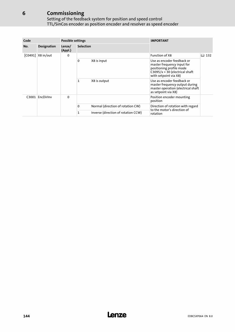
CommissioningSetting of the feedback system for position and speed controlTTL/SinCos encoder as position encoder and resolver as speed encoder
6
� 144 EDBCSXP064 EN 8.0
IMPORTANTPossible settingsCode
SelectionLenze/{Appl.}
DesignationNo.
[C0491] X8 in/out 0 Function of X8 � 132
0 X8 is input Use as encoder feedback ormaster frequency input forpositioning profile modeC3095/x = 30 (electrical shaftwith setpoint via X8)
1 X8 is output Use as encoder feedback ormaster frequency output duringmaster operation (electrical shaftas setpoint via X8)
C3001 EncDirInv 0 Position encoder mountingposition
0 Normal (direction of rotation CW) Direction of rotation with regardto the motor’s direction ofrotation1 Inverse (direction of rotation CCW)

CommissioningSetting of the feedback system for position and speed control
Absolute value encoder as position and speed encoder
6
� 145EDBCSXP064 EN 8.0
6.9.5 Absolute value encoder as position and speed encoder
� Danger!
Valid when using an operating software up to and including V7.0:
When absolute value encoders are used, uncontrolled movements of the driveare possible!
If an absolute value encoder is disconnected from the axis module duringoperation, the fault OH3−TRIP occurs. If the absolute value encoder now isconnected to X8 again and a TRIP−RESET is carried out, the drive may start up inan uncontrolled manner with a high speed and a high torque. A SD8−TRIP willnot occur, as would be expected.
Possible consequences:
ƒ Death or severe injuries
ƒ Destruction or damage of the machine/drive
Protective measures:
ƒ If a fault (trip) occurs during commissioning when an absolute valueencoder is used, check the history buffer C0168. If an Sd8−TRIP is at thesecond or third place, a reinitialisation is absolutely necessary. For thispurpose, switch off and on again the 24−V supply of the control electronics.
� Note!
For initial commissioning of an absolute value encoder, after an encoder,controller or motor replacement, or for modifications regarding themechanics, carry out a positioning process with the positioning profile mode"Set reference" ( 119).
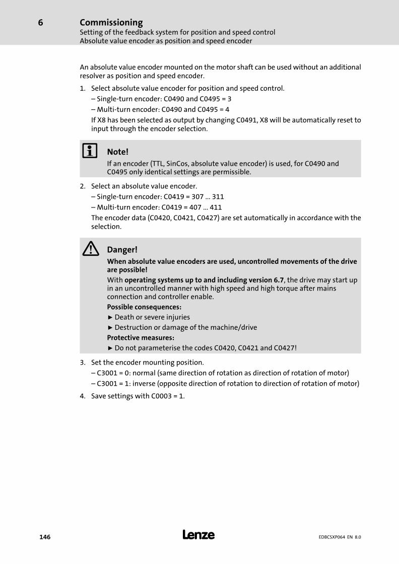
CommissioningSetting of the feedback system for position and speed controlAbsolute value encoder as position and speed encoder
6
� 146 EDBCSXP064 EN 8.0
An absolute value encoder mounted on the motor shaft can be used without an additionalresolver as position and speed encoder.
1. Select absolute value encoder for position and speed control.
– Single−turn encoder: C0490 and C0495 = 3
– Multi−turn encoder: C0490 and C0495 = 4
If X8 has been selected as output by changing C0491, X8 will be automatically reset toinput through the encoder selection.
� Note!
If an encoder (TTL, SinCos, absolute value encoder) is used, for C0490 andC0495 only identical settings are permissible.
2. Select an absolute value encoder.
– Single−turn encoder: C0419 = 307 ... 311
– Multi−turn encoder: C0419 = 407 ... 411
The encoder data (C0420, C0421, C0427) are set automatically in accordance with theselection.
� Danger!
When absolute value encoders are used, uncontrolled movements of the driveare possible!
With operating systems up to and including version 6.7, the drive may start upin an uncontrolled manner with high speed and high torque after mainsconnection and controller enable.
Possible consequences:
ƒ Death or severe injuries
ƒ Destruction or damage of the machine/drive
Protective measures:
ƒ Do not parameterise the codes C0420, C0421 and C0427!
3. Set the encoder mounting position.
– C3001 = 0: normal (same direction of rotation as direction of rotation of motor)
– C3001 = 1: inverse (opposite direction of rotation to direction of rotation of motor)
4. Save settings with C0003 = 1.
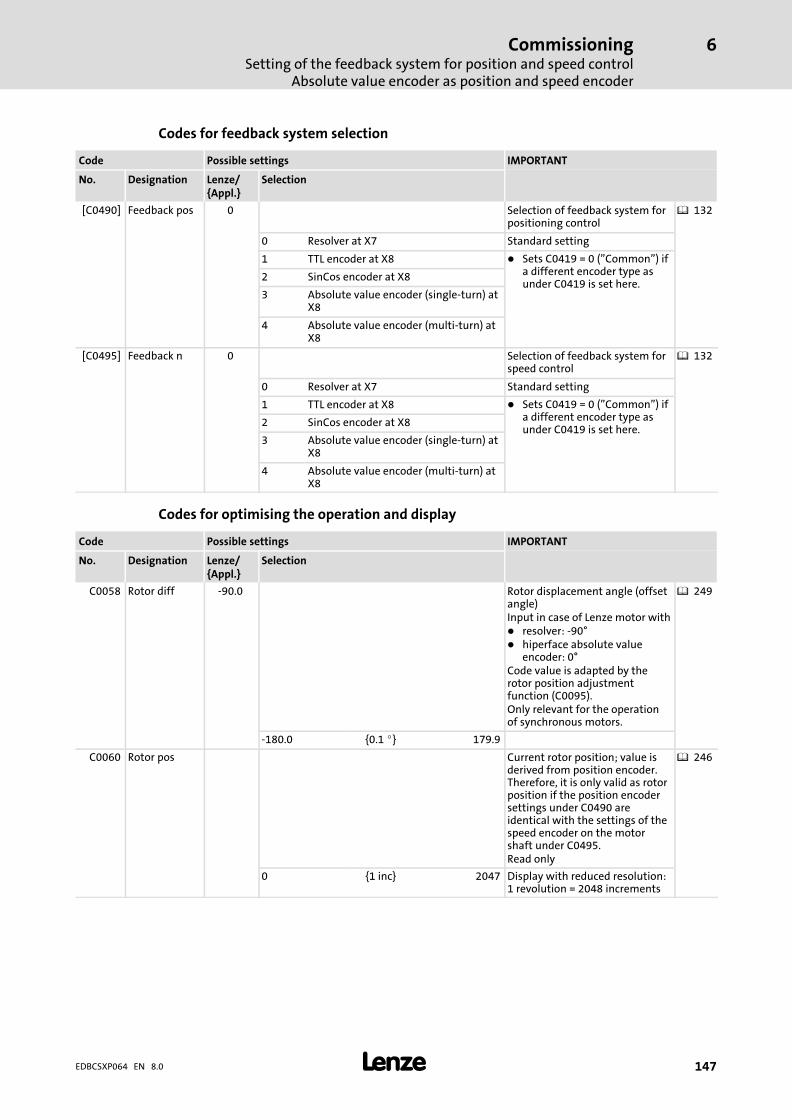
CommissioningSetting of the feedback system for position and speed control
Absolute value encoder as position and speed encoder
6
� 147EDBCSXP064 EN 8.0
Codes for feedback system selection
Code Possible settings IMPORTANT
No. Designation Lenze/{Appl.}
Selection
[C0490] Feedback pos 0 Selection of feedback system forpositioning control
� 132
0 Resolver at X7 Standard setting
1 TTL encoder at X8 � Sets C0419 = 0 ("Common") ifa different encoder type asunder C0419 is set here.
2 SinCos encoder at X8
3 Absolute value encoder (single−turn) atX8
4 Absolute value encoder (multi−turn) atX8
[C0495] Feedback n 0 Selection of feedback system forspeed control
� 132
0 Resolver at X7 Standard setting
1 TTL encoder at X8 � Sets C0419 = 0 ("Common") ifa different encoder type asunder C0419 is set here.
2 SinCos encoder at X8
3 Absolute value encoder (single−turn) atX8
4 Absolute value encoder (multi−turn) atX8
Codes for optimising the operation and display
Code Possible settings IMPORTANT
No. Designation Lenze/{Appl.}
Selection
C0058 Rotor diff −90.0 Rotor displacement angle (offsetangle)Input in case of Lenze motor with� resolver: −90°� hiperface absolute value
encoder: 0°Code value is adapted by therotor position adjustmentfunction (C0095).Only relevant for the operationof synchronous motors.
� 249
−180.0 {0.1 �} 179.9
C0060 Rotor pos Current rotor position; value isderived from position encoder.Therefore, it is only valid as rotorposition if the position encodersettings under C0490 areidentical with the settings of thespeed encoder on the motorshaft under C0495.Read only
� 246
0 {1 inc} 2047 Display with reduced resolution:1 revolution = 2048 increments

CommissioningSetting of the feedback system for position and speed controlAbsolute value encoder as position and speed encoder
6
� 148 EDBCSXP064 EN 8.0
IMPORTANTPossible settingsCode
SelectionLenze/{Appl.}
DesignationNo.
[C0095] Rotor pos adj 0 Activation of rotor positionadjustment for automaticdetermination of the rotordisplacement angle.C0058 displays the determinedrotor displacement angle (offsetangle).
� 249
0 Inactive
1 Active
[C0419] Enc. setup 110 Encoder selection� Selection of encoder type
indicated on the nameplate ofthe Lenze motor.
� The encoder data (C0420,C0421, C0427) is setautomatically in accordancewith the selection.
� 136� 145
0 Common
110 IT512−5V Incremental encoder with TTLlevel111 IT1024−5V
112 IT2048−5V
113 IT4096−5V
210 IS512−5V SinCos encoder
211 IS1024−5V
212 IS2048−5V
213 IS4096−5V
307 AS64−8V SinCos absolute value encoderwith Hiperface® interface(single−turn)Selections 307, 308, 309 are onlypossible with operating system7.0 or higher.
308 AS128−8V
309 AS256−8V
310 AS512−8V
311 AS1024−8V
407 AM64−8V SinCos absolute value encoderwith Hiperface® interface(multi−turn)Selections 407, 408, 409 are onlypossible with operating system7.0 or higher.
408 AM128−8V
409 AM256−8V
410 AM512−8V
411 AM1024−8V
[C0420] Encoder const. 512 Number of increments of theencoder
� 136� 145
1 {1 inc/rev} 8192 Sets C0419 = 0 ("common") if thevalue is altered.
[C0421] Encoder volt 0 Encoder voltage � 136� 1450 5.0 V Sets C0419 = 0 ("common") if the
value is altered.1 5.6 V
2 6.3 V
3 6.9 V
4 7.5 V
5 8.1 V

CommissioningSetting of the feedback system for position and speed control
Absolute value encoder as position and speed encoder
6
� 149EDBCSXP064 EN 8.0
IMPORTANTPossible settingsCode
SelectionLenze/{Appl.}
DesignationNo.
[C0427] Enc. signal 0 Function of the master frequencyinput signals on X8 (DFIN)
� 136� 145
0 2−phase
1 A: speedB: direction
2 A or B: speed or direction
[C0491] X8 in/out 0 Function of X8 � 132
0 X8 is input Use as encoder feedback ormaster frequency input forpositioning profile modeC3095/x = 30 (electrical shaftwith setpoint via X8)
1 X8 is output Use as encoder feedback ormaster frequency output duringmaster operation (electrical shaftas setpoint via X8)
C3001 EncDirInv 0 Position encoder mountingposition
0 Normal (direction of rotation CW) Direction of rotation with regardto the motor’s direction ofrotation1 Inverse (direction of rotation CCW)
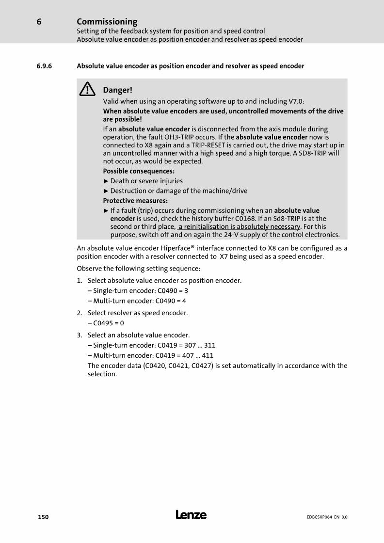
CommissioningSetting of the feedback system for position and speed controlAbsolute value encoder as position encoder and resolver as speed encoder
6
� 150 EDBCSXP064 EN 8.0
6.9.6 Absolute value encoder as position encoder and resolver as speed encoder
� Danger!
Valid when using an operating software up to and including V7.0:
When absolute value encoders are used, uncontrolled movements of the driveare possible!
If an absolute value encoder is disconnected from the axis module duringoperation, the fault OH3−TRIP occurs. If the absolute value encoder now isconnected to X8 again and a TRIP−RESET is carried out, the drive may start up inan uncontrolled manner with a high speed and a high torque. A SD8−TRIP willnot occur, as would be expected.
Possible consequences:
ƒ Death or severe injuries
ƒ Destruction or damage of the machine/drive
Protective measures:
ƒ If a fault (trip) occurs during commissioning when an absolute valueencoder is used, check the history buffer C0168. If an Sd8−TRIP is at thesecond or third place, a reinitialisation is absolutely necessary. For thispurpose, switch off and on again the 24−V supply of the control electronics.
An absolute value encoder Hiperface® interface connected to X8 can be configured as aposition encoder with a resolver connected to X7 being used as a speed encoder.
Observe the following setting sequence:
1. Select absolute value encoder as position encoder.
– Single−turn encoder: C0490 = 3
– Multi−turn encoder: C0490 = 4
2. Select resolver as speed encoder.
– C0495 = 0
3. Select an absolute value encoder.
– Single−turn encoder: C0419 = 307 ... 311
– Multi−turn encoder: C0419 = 407 ... 411
The encoder data (C0420, C0421, C0427) is set automatically in accordance with theselection.
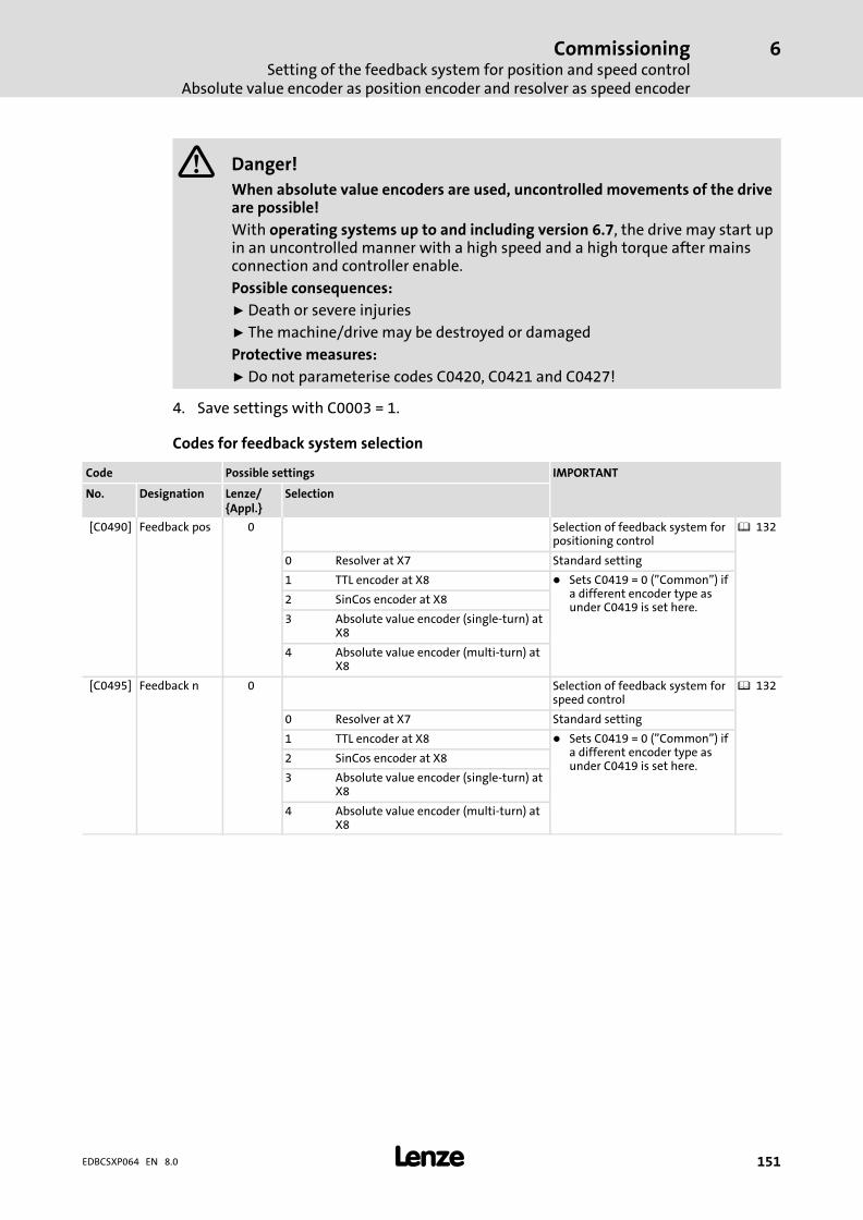
CommissioningSetting of the feedback system for position and speed control
Absolute value encoder as position encoder and resolver as speed encoder
6
� 151EDBCSXP064 EN 8.0
� Danger!
When absolute value encoders are used, uncontrolled movements of the driveare possible!
With operating systems up to and including version 6.7, the drive may start upin an uncontrolled manner with a high speed and a high torque after mainsconnection and controller enable.
Possible consequences:
ƒ Death or severe injuries
ƒ The machine/drive may be destroyed or damaged
Protective measures:
ƒ Do not parameterise codes C0420, C0421 and C0427!
4. Save settings with C0003 = 1.
Codes for feedback system selection
Code Possible settings IMPORTANT
No. Designation Lenze/{Appl.}
Selection
[C0490] Feedback pos 0 Selection of feedback system forpositioning control
� 132
0 Resolver at X7 Standard setting
1 TTL encoder at X8 � Sets C0419 = 0 ("Common") ifa different encoder type asunder C0419 is set here.
2 SinCos encoder at X8
3 Absolute value encoder (single−turn) atX8
4 Absolute value encoder (multi−turn) atX8
[C0495] Feedback n 0 Selection of feedback system forspeed control
� 132
0 Resolver at X7 Standard setting
1 TTL encoder at X8 � Sets C0419 = 0 ("Common") ifa different encoder type asunder C0419 is set here.
2 SinCos encoder at X8
3 Absolute value encoder (single−turn) atX8
4 Absolute value encoder (multi−turn) atX8

CommissioningSetting of the feedback system for position and speed controlAbsolute value encoder as position encoder and resolver as speed encoder
6
� 152 EDBCSXP064 EN 8.0
Codes for optimising the operation and display
Code Possible settings IMPORTANT
No. Designation Lenze/{Appl.}
Selection
C0058 Rotor diff −90.0 Rotor displacement angle (offsetangle)Input in case of Lenze motor with� resolver: −90°� hiperface absolute value
encoder: 0°Code value is adapted by therotor position adjustmentfunction (C0095).Only relevant for the operationof synchronous motors.
� 249
−180.0 {0.1 �} 179.9
C0060 Rotor pos Current rotor position; value isderived from position encoder.Therefore, it is only valid as rotorposition if the position encodersettings under C0490 areidentical with the settings of thespeed encoder on the motorshaft under C0495.Read only
� 246
0 {1 inc} 2047 Display with reduced resolution:1 revolution = 2048 increments
[C0080] Res pole no. 1 Number of pole pairs of resolver
1 {1} 10
[C0095] Rotor pos adj 0 Activation of rotor positionadjustment for automaticdetermination of the rotordisplacement angle.C0058 displays the determinedrotor displacement angle (offsetangle).
� 249
0 Inactive
1 Active
C0414 DIS: ResQual. Resolver modulationQuality of the resolver excitationamplitude set under C0416(recommendation: 0.5 ... 1.2;ideal 1.0)
� 133
0.00 {0.01} 1,60
[C0416] Resolver adj. 5 Resolver excitation amplitude � 133
0 100 %
1 80 %
2 68 %
3 58 %
4 50 %
5 45 %
6 40 %
7 37 %
[C0417] Resolver cor. 0 Resolver adjustment � 257
0 Ready
1 Start adjustment
2 Loading default values

CommissioningSetting of the feedback system for position and speed control
Absolute value encoder as position encoder and resolver as speed encoder
6
� 153EDBCSXP064 EN 8.0
IMPORTANTPossible settingsCode
SelectionLenze/{Appl.}
DesignationNo.
[C0419] Enc. setup 110 Encoder selection� Selection of encoder type
indicated on the nameplate ofthe Lenze motor.
� The encoder data (C0420,C0421, C0427) is setautomatically in accordancewith the selection.
� 136� 145
0 Common
110 IT512−5V Incremental encoder with TTLlevel111 IT1024−5V
112 IT2048−5V
113 IT4096−5V
210 IS512−5V SinCos encoder
211 IS1024−5V
212 IS2048−5V
213 IS4096−5V
307 AS64−8V SinCos absolute value encoderwith Hiperface® interface(single−turn)Selections 307, 308, 309 are onlypossible with operating system7.0 or higher.
308 AS128−8V
309 AS256−8V
310 AS512−8V
311 AS1024−8V
407 AM64−8V SinCos absolute value encoderwith Hiperface® interface(multi−turn)Selections 407, 408, 409 are onlypossible with operating system7.0 or higher.
408 AM128−8V
409 AM256−8V
410 AM512−8V
411 AM1024−8V
[C0420] Encoder const. 512 Number of increments of theencoder
� 136� 145
1 {1 inc/rev} 8192 Sets C0419 = 0 ("common") if thevalue is altered.
[C0421] Encoder volt 0 Encoder voltage � 136� 1450 5.0 V Sets C0419 = 0 ("common") if the
value is altered.1 5.6 V
2 6.3 V
3 6.9 V
4 7.5 V
5 8.1 V
[C0427] Enc. signal 0 Function of the master frequencyinput signals on X8 (DFIN)
� 136� 145
0 2−phase
1 A: speedB: direction
2 A or B: speed or direction
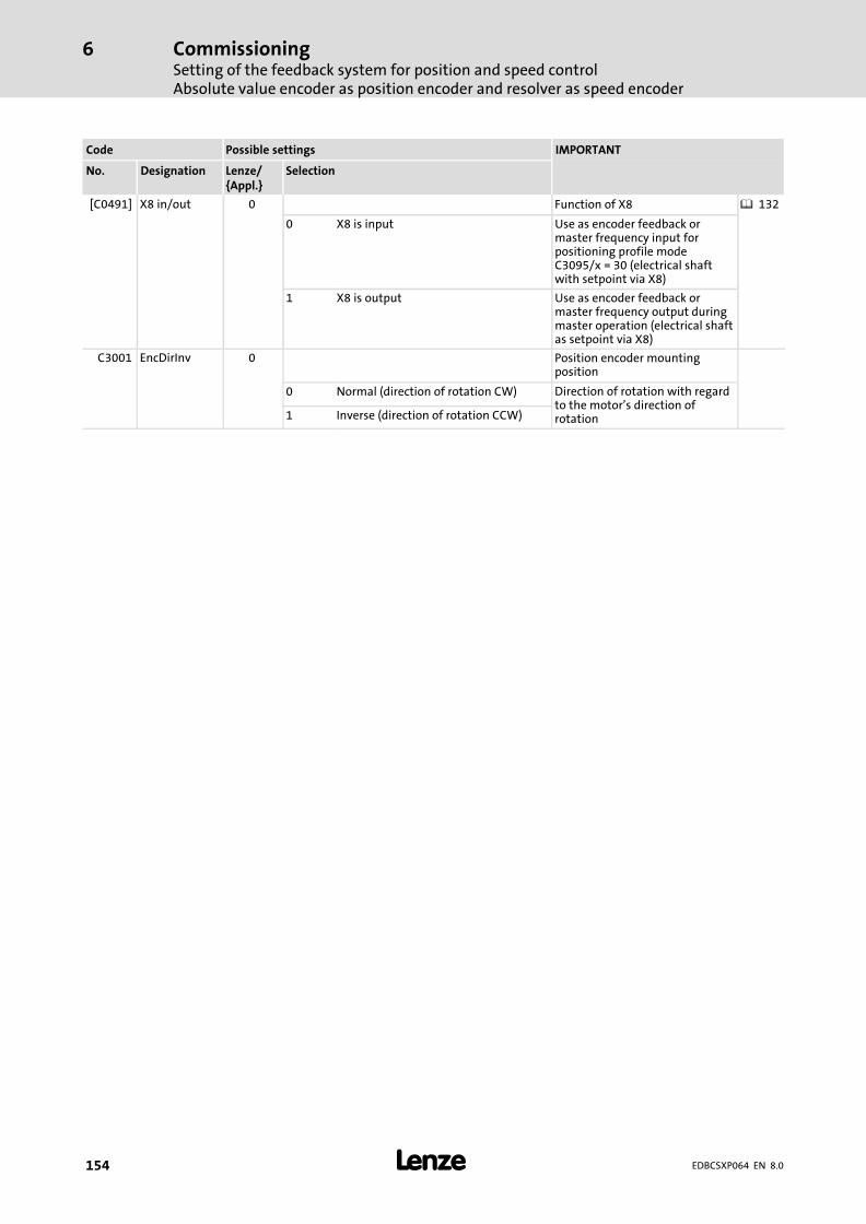
CommissioningSetting of the feedback system for position and speed controlAbsolute value encoder as position encoder and resolver as speed encoder
6
� 154 EDBCSXP064 EN 8.0
IMPORTANTPossible settingsCode
SelectionLenze/{Appl.}
DesignationNo.
[C0491] X8 in/out 0 Function of X8 � 132
0 X8 is input Use as encoder feedback ormaster frequency input forpositioning profile modeC3095/x = 30 (electrical shaftwith setpoint via X8)
1 X8 is output Use as encoder feedback ormaster frequency output duringmaster operation (electrical shaftas setpoint via X8)
C3001 EncDirInv 0 Position encoder mountingposition
0 Normal (direction of rotation CW) Direction of rotation with regardto the motor’s direction ofrotation1 Inverse (direction of rotation CCW)
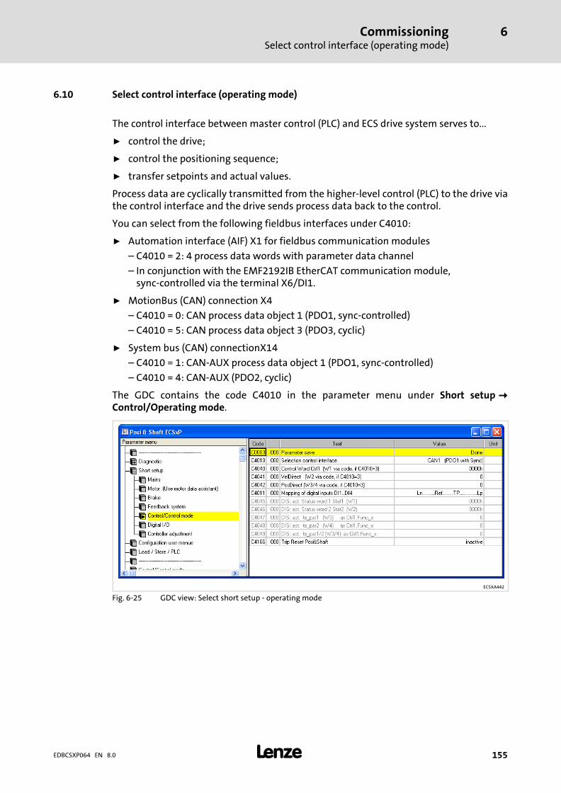
CommissioningSelect control interface (operating mode)
6
� 155EDBCSXP064 EN 8.0
6.10 Select control interface (operating mode)
The control interface between master control (PLC) and ECS drive system serves to...
ƒ control the drive;
ƒ control the positioning sequence;
ƒ transfer setpoints and actual values.
Process data are cyclically transmitted from the higher−level control (PLC) to the drive viathe control interface and the drive sends process data back to the control.
You can select from the following fieldbus interfaces under C4010:
ƒ Automation interface (AIF) X1 for fieldbus communication modules
– C4010 = 2: 4 process data words with parameter data channel
– In conjunction with the EMF2192IB EtherCAT communication module,sync−controlled via the terminal X6/DI1.
ƒ MotionBus (CAN) connection X4
– C4010 = 0: CAN process data object 1 (PDO1, sync−controlled)
– C4010 = 5: CAN process data object 3 (PDO3, cyclic)
ƒ System bus (CAN) connectionX14
– C4010 = 1: CAN−AUX process data object 1 (PDO1, sync−controlled)
– C4010 = 4: CAN−AUX (PDO2, cyclic)
The GDC contains the code C4010 in the parameter menu under Short setup��Control/Operating mode.
ECSXA442
Fig. 6−25 GDC view: Select short setup − operating mode
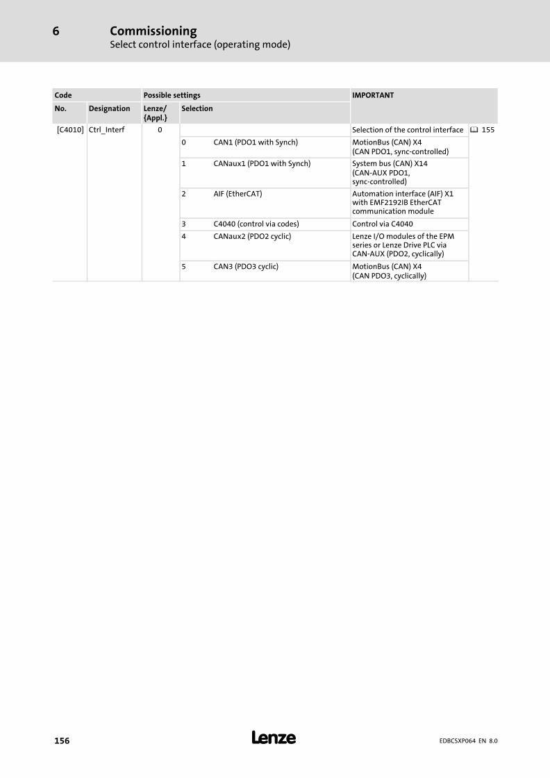
CommissioningSelect control interface (operating mode)
6
� 156 EDBCSXP064 EN 8.0
Code Possible settings IMPORTANT
No. Designation Lenze/{Appl.}
Selection
[C4010] Ctrl_Interf 0 Selection of the control interface � 155
0 CAN1 (PDO1 with Synch) MotionBus (CAN) X4(CAN PDO1, sync−controlled)
1 CANaux1 (PDO1 with Synch) System bus (CAN) X14(CAN−AUX PDO1,sync−controlled)
2 AIF (EtherCAT) Automation interface (AIF) X1with EMF2192IB EtherCATcommunication module
3 C4040 (control via codes) Control via C4040
4 CANaux2 (PDO2 cyclic) Lenze I/O modules of the EPMseries or Lenze Drive PLC viaCAN−AUX (PDO2, cyclically)
5 CAN3 (PDO3 cyclic) MotionBus (CAN) X4(CAN PDO3, cyclically)

CommissioningSelect control interface (operating mode)
6
� 157EDBCSXP064 EN 8.0
Control with codes via parameter communication
� Note!
C4010 = 3 (control via C4040), to control the drive for test and commissioningpurposes via codes in the GDC. The following codes serve to manually definethe process data words for test purposes:
ƒ C4040 control word Ctrl1 (Word 1)
ƒ C4041 VelDirect (Word 2)
ƒ C4042 PosDirect (Word 3/4)
Codes C4040, C4041 and C4042 can be found in the GDC parameter menu under Shortsetup � Control/Operating mode.
Profile 15
Profile ...
Profile 2
Profile 1
v
tDirect modes
Control word:
Profile No.
CinhJog CWJog CCWTRIP-RESET...
Prof enable
HomingManual operationPoint to point positioningTouch probe positioningEShaft
Brake logic
Positioning Control
Profiles
ECSxP
AuxProfileBusyProfile dataProfEnable
C4010
PosProfiler
Byte1
Byte2
Byte3
Byte4
Byte5
Byte6
Byte7
Byte8
Co
ntr
olw
ord
Process data In
C4040 AppControlC4041 AppWord 2C4042 AppWord 3/4
CAN-In
CAN-AUX-In
AIF-In
X14
X1
X4
ECSXA399
Fig. 6−26 Control interface

CommissioningProcess data to the axis module (control word Ctrl1 and setpoints)
6
� 158 EDBCSXP064 EN 8.0
6.11 Process data to the axis module (control word Ctrl1 and setpoints)
Process data is transmitted cyclically to the drive via the control interface set under C4010with a data width of 8 bytes or 4 words.
The telegram structure of the 8 byte process data to the drive is the same for all selectablecontrol interfaces. In addition to the control word Ctrl1 (Word 1), Word 2, Word 3 and Word4 are available for setpoints.
Control bit 15 of the control word Ctrl1 serves to set the assignment of the words 2 ... 4.
Assignment of the process data to the drive:
Word 1 Word 2 DWord (word 3 + word 4)
LOW byte HIGH byte LOW byte HIGH byte LOW word HIGH word
Byte 1 Byte 2 Byte 3 Byte 4 Byte 5 Byte 6 Byte 7 Byte 8
Ctrl1.Bit15 = 0
Control wordCtrl1
rx_par1 rx_par2 rx_par3
Ctrl1.Bit15 = 1 VelDirect PosDirect

CommissioningProcess data to the axis module (control word Ctrl1 and setpoints)
Control word Ctrl1
6
� 159EDBCSXP064 EN 8.0
6.11.1 Control word Ctrl1
The control word Ctrl1 contains the following control bits:
Bit Name Level Meaning
0 Func1 HIGH active Signal selection tx_par1/2, binary coded 20
1 Func2 HIGH active Signal selection tx_par1/2, binary coded 21
2 Func4 HIGH active Signal selection tx_par1/2, binary coded 22
3 Quick stop(QSP)
HIGH active Quick stop (QSP):� 0 = No QSP active� 1 = QSP active
– The drive is braked to a standstill within the QSP deceleration time(C0150).
– Change to "Stand−by".
4 PNoSet_1 HIGH active Selection of the positioning profile (binary coded 20)
5 PNoSet_2 HIGH active Selection of the positioning profile (binary coded 21)
6 PNoSet_4 HIGH active Selection of the positioning profile (binary coded 22)
7 PNoSet_8 HIGH active Selection of the positioning profile (binary coded 23)
8 ProfEnable HIGH active Start positioning profile:� 0 = brakes to standstill with current QSP deceleration time (C0150)
– Change to "Stand−by".– Completing the positioning profiles with profile mode "constant
travel".– Activating the brake when brake logic is active.
� 1 = start positioning profile (PNoSet_x > 0)– If status bit Stat1.ProfileBusy = 0 and Stat2.AuxProfileBusy = 0, the
positioning profile concerned can be started immediately by theselection of a new profile number (PNoSet_x).
9 CINH HIGH active Controller inhibit (CINH) − change to "Stand−by":� 0 = deactivation of ctrl. inhibit� 1 = activation of ctrl. inhibit
– The power output stages are inhibited.– All internal controllers are reset.
10 TripSet HIGH active Change to "Trouble":� The drive is decelerated to standstill within the QSP deceleration time
(C0150).� 0 = do not set fault message� 1 = set fault message
11 TripReset Rising edge Fault message reset − change to "Stand−by":� 0−1 edge = reset fault message
– This function resets an active fault message provided that the causeof the fault has been removed. If the cause of the fault is still active,there will be no reaction.
12 JogCCW HIGH active Manual jog in negative direction of rotation (CCW)� 0 = change to "Stand−by"� 1 = manual jog in negative direction of rotation (CCW), "ManualJog"
status
13 JogCW HIGH active Manual jog in positive direction of rotation (CW)� 0 = change to "Stand−by"� 1 = manual jog in positive direction of rotation (CW), "ManualJog"
status
14 RelLimSwitch HIGH active Activation of "retracting on/off switch" function.
15 PosDirect HIGH active Selection for setpoints in words 2 ... 4 of the process input data:� 0 = rx_par1, rx_par2, rx_par3� 1 = VelDirect, PosDirect for direct positioning (C3095/x = 110 ... 113)

CommissioningProcess data to the axis module (control word Ctrl1 and setpoints)Setpoint data words to the controller (VelDirect, PosDirect, rx_par1..3)
6
� 160 EDBCSXP064 EN 8.0
6.11.2 Setpoint data words to the controller (VelDirect, PosDirect, rx_par1..3)
ƒ The data word "rx_par1" is used for speed override with ECS "Posi&Shaft".
ƒ The data words "rx_par2" and "rx_par3" are currently not used with ESC "Posi andShaft".
ƒ The data words "VelDirect" and "PosDirect" are used for the positioning modes with"direct positioning" (C3095/x = 110 ... 113, � 198). The control bit 15 in the controlword Ctrl1 must be set to use the data words as VelDirect and PosDirect.
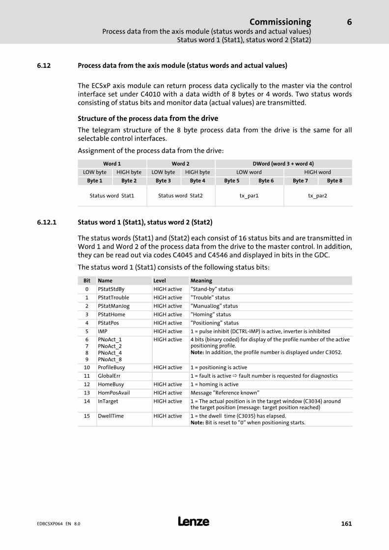
CommissioningProcess data from the axis module (status words and actual values)
Status word 1 (Stat1), status word 2 (Stat2)
6
� 161EDBCSXP064 EN 8.0
6.12 Process data from the axis module (status words and actual values)
The ECSxP axis module can return process data cyclically to the master via the controlinterface set under C4010 with a data width of 8 bytes or 4 words. Two status wordsconsisting of status bits and monitor data (actual values) are transmitted.
Structure of the process data from the drive
The telegram structure of the 8 byte process data from the drive is the same for allselectable control interfaces.
Assignment of the process data from the drive:
Word 1 Word 2 DWord (word 3 + word 4)
LOW byte HIGH byte LOW byte HIGH byte LOW word HIGH word
Byte 1 Byte 2 Byte 3 Byte 4 Byte 5 Byte 6 Byte 7 Byte 8
Status word Stat1 Status word Stat2 tx_par1 tx_par2
6.12.1 Status word 1 (Stat1), status word 2 (Stat2)
The status words (Stat1) and (Stat2) each consist of 16 status bits and are transmitted inWord 1 and Word 2 of the process data from the drive to the master control. In addition,they can be read out via codes C4045 and C4546 and displayed in bits in the GDC.
The status word 1 (Stat1) consists of the following status bits:
Bit Name Level Meaning
0 PStatStdBy HIGH active "Stand−by" status
1 PStatTrouble HIGH active "Trouble" status
2 PStatManJog HIGH active "ManualJog" status
3 PStatHome HIGH active "Homing" status
4 PStatPos HIGH active "Positioning" status
5 IMP HIGH active 1 = pulse inhibit (DCTRL−IMP) is active, inverter is inhibited
6789
PNoAct_1PNoAct_2PNoAct_4PNoAct_8
HIGH active 4 bits (binary coded) for display of the profile number of the activepositioning profile.Note: In addition, the profile number is displayed under C3052.
10 ProfileBusy HIGH active 1 = positioning is active
11 GlobalErr 1 = fault is active fault number is requested for diagnostics
12 HomeBusy HIGH active 1 = homing is active
13 HomPosAvail HIGH active Message "Reference known"
14 InTarget HIGH active 1 = The actual position is in the target window (C3034) aroundthe target position (message: target position reached)
15 DwellTime HIGH active 1 = the dwell time (C3035) has elapsed.Note: Bit is reset to "0" when positioning starts.

CommissioningProcess data from the axis module (status words and actual values)Status word 1 (Stat1), status word 2 (Stat2)
6
� 162 EDBCSXP064 EN 8.0
The status word 2 (Stat2) consists of the following status bits:
Bit Name Level Meaning
0 Mmax HIGH active 1 = "Maximum torque" reached (value: C0057 x C3910)
1 Imax HIGH active 1 = maximum current reached (value: C0022)
2 Nmin HIGH active 1 = value falls below speed threshold (C3017)Note: Hysteresis is set with C3018.
3 ProfMlimAct HIGH active 1 = Profile function torque reduction is active
4 FollowErrWarn HIGH active 1 = Following error tolerance C3030 for warning has exceeded
5 CANSyncInWin HIGH active Control program synchronisation:1 = Drive is synchronised to CAN sync telegram
6 ProfCont HIGH active 1 = profile continuation after profile stop possible
7 SwLimErr HIGH active 1 = software limit position reached
8 QspIn HIGH active 1 = quick stop active
9 AuxProfileBusy HIGH active 1 = touch probe positioning active
10...12
Not assigned
131415
Func1Func2Func4
HIGH active 3 bits (binary coded) for display of the monitor data transmittedin tx_par1/2 (Word 3/4) in the same process data telegram.
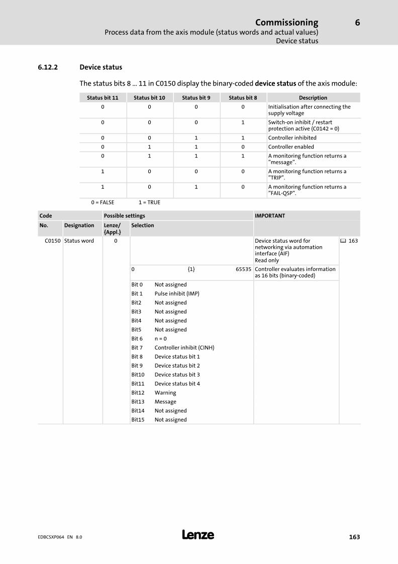
CommissioningProcess data from the axis module (status words and actual values)
Device status
6
� 163EDBCSXP064 EN 8.0
6.12.2 Device status
The status bits 8 ... 11 in C0150 display the binary−coded device status of the axis module:
Status bit 11 Status bit 10 Status bit 9 Status bit 8 Description
0 0 0 0 Initialisation after connecting thesupply voltage
0 0 0 1 Switch−on inhibit / restartprotection active (C0142 = 0)
0 0 1 1 Controller inhibited
0 1 1 0 Controller enabled
0 1 1 1 A monitoring function returns a"message".
1 0 0 0 A monitoring function returns a"TRIP".
1 0 1 0 A monitoring function returns a"FAIL−QSP".
0 = FALSE 1 = TRUE
Code Possible settings IMPORTANT
No. Designation Lenze/{Appl.}
Selection
C0150 Status word 0 Device status word fornetworking via automationinterface (AIF)Read only
� 163
0 {1} 65535 Controller evaluates informationas 16 bits (binary−coded)
Bit 0 Not assigned
Bit 1 Pulse inhibit (IMP)
Bit2 Not assigned
Bit3 Not assigned
Bit4 Not assigned
Bit5 Not assigned
Bit 6 n = 0
Bit 7 Controller inhibit (CINH)
Bit 8 Device status bit 1
Bit 9 Device status bit 2
Bit10 Device status bit 3
Bit11 Device status bit 4
Bit12 Warning
Bit13 Message
Bit14 Not assigned
Bit15 Not assigned

CommissioningProcess data from the axis module (status words and actual values)Monitor data words from the controller (tx_par1 und tx_par2)
6
� 164 EDBCSXP064 EN 8.0
6.12.3 Monitor data words from the controller (tx_par1 und tx_par2)
The monitor data words "tx_par1" and "tx_par2" can be assigned with various displayvalues via control bits in the control word Ctrl1:
ƒ Control bit 0 ("Ctrl1−Func1")
ƒ Control bit 1 ("Ctrl1−Func2")
ƒ Control bit 2 ("Ctrl1−Func4")
The following assignment of the monitor data words can be set via the control bits:
Control bits 0..2in the controlword Ctrl1[binary]
Monitor data word
tx_par1 tx_par2
...000 Actual position (216 == 1 position encoder revolution)
...001 FollowErr (216 == 1 position encoder revolution)
...010 Actual speed value nactScaling: 214 == C0011 (maximum speed)
Actual torque MactScaling: 214 == C0057 (calculated maximumtorque)
...011 Not assigned
...100 Not assigned
...101 Fault number DCTRL_wStat (C0150)Bit assignment: See code list
...110 Profile generator state (C3066)Bit assignment: See code list
Not assigned
...111 AIn1 DigIn
Bit assignment� Bits 0 ... 12: image of analog input� Bits 13, 14, 15: 0 (no function)
Bit assignment� Bit 0 (x6/DI1): image of digital input 1� Bit 1 (X6/DI2): image of digital input 2� Bit 2 (X6/DI3): image of digital input 3� Bit 3 (x6/DI4): image of digital input 4� Bits 4 ... 15: 0 (no function)
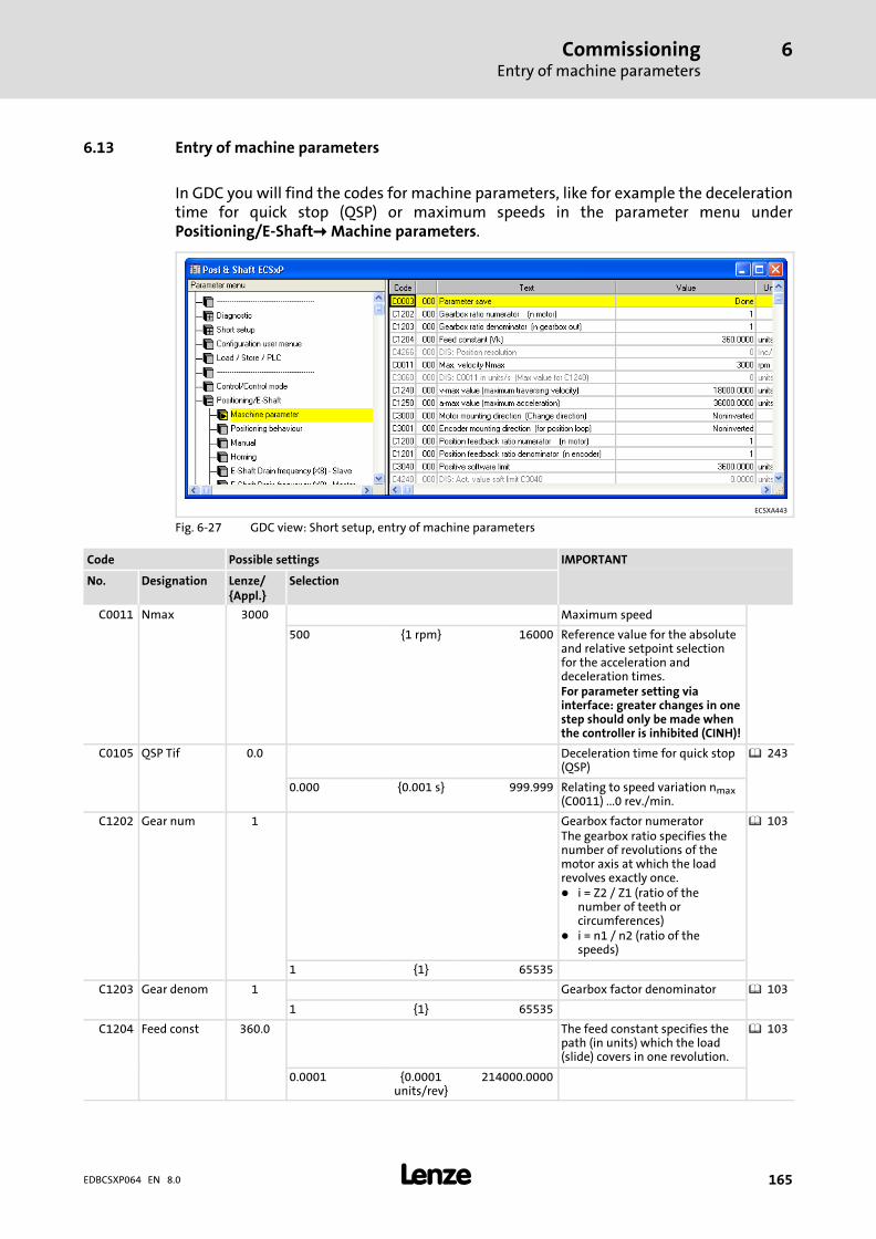
CommissioningEntry of machine parameters
6
� 165EDBCSXP064 EN 8.0
6.13 Entry of machine parameters
In GDC you will find the codes for machine parameters, like for example the decelerationtime for quick stop (QSP) or maximum speeds in the parameter menu underPositioning/E−Shaft� Machine parameters.
ECSXA443
Fig. 6−27 GDC view: Short setup, entry of machine parameters
Code Possible settings IMPORTANT
No. Designation Lenze/{Appl.}
Selection
C0011 Nmax 3000 Maximum speed
500 {1 rpm} 16000 Reference value for the absoluteand relative setpoint selectionfor the acceleration anddeceleration times.For parameter setting viainterface: greater changes in onestep should only be made whenthe controller is inhibited (CINH)!
C0105 QSP Tif 0.0 Deceleration time for quick stop(QSP)
� 243
0.000 {0.001 s} 999.999 Relating to speed variation nmax(C0011) ...0 rev./min.
C1202 Gear num 1 Gearbox factor numeratorThe gearbox ratio specifies thenumber of revolutions of themotor axis at which the loadrevolves exactly once.� i = Z2 / Z1 (ratio of the
number of teeth orcircumferences)
� i = n1 / n2 (ratio of thespeeds)
� 103
1 {1} 65535
C1203 Gear denom 1 Gearbox factor denominator � 103
1 {1} 65535
C1204 Feed const 360.0 The feed constant specifies thepath (in units) which the load(slide) covers in one revolution.
� 103
0.0001 {0.0001units/rev}
214000.0000
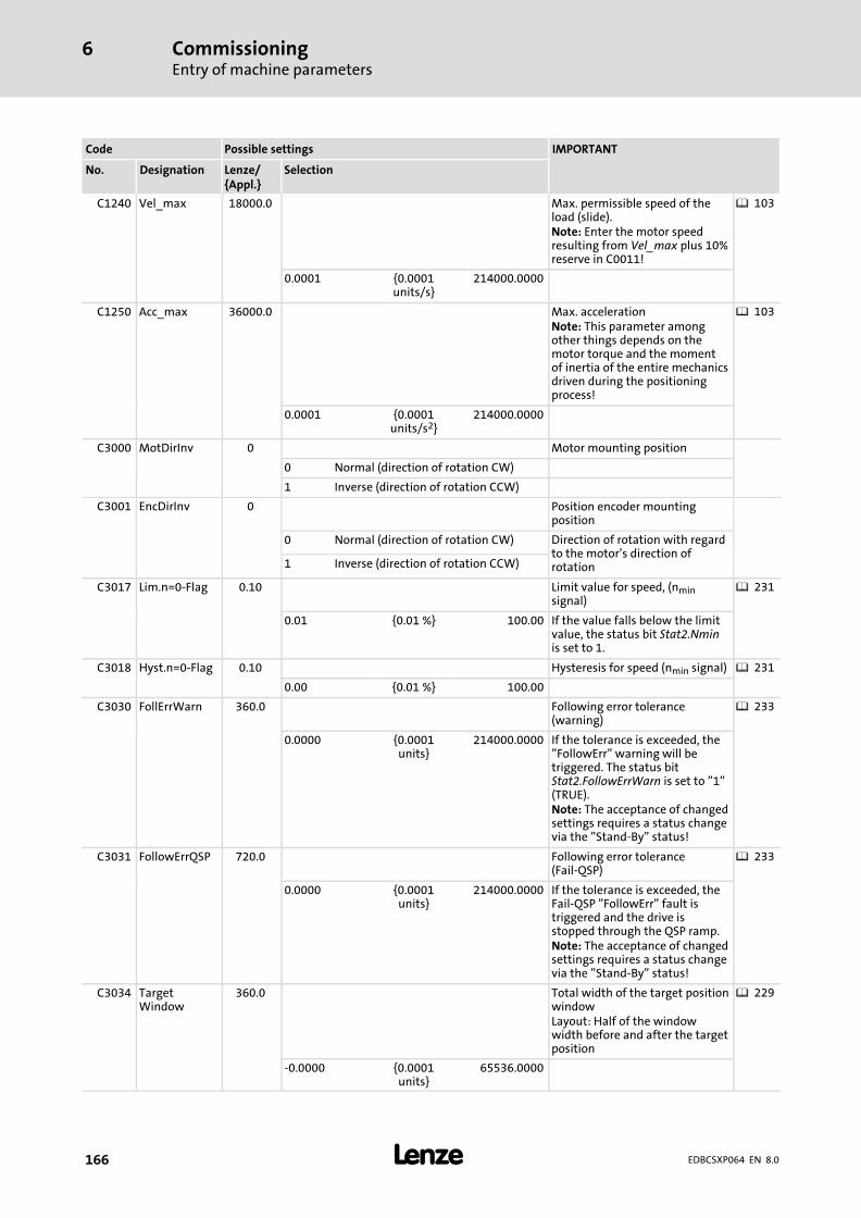
CommissioningEntry of machine parameters
6
� 166 EDBCSXP064 EN 8.0
IMPORTANTPossible settingsCode
SelectionLenze/{Appl.}
DesignationNo.
C1240 Vel_max 18000.0 Max. permissible speed of theload (slide).Note: Enter the motor speedresulting from Vel_max plus 10%reserve in C0011!
� 103
0.0001 {0.0001units/s}
214000.0000
C1250 Acc_max 36000.0 Max. accelerationNote: This parameter amongother things depends on themotor torque and the momentof inertia of the entire mechanicsdriven during the positioningprocess!
� 103
0.0001 {0.0001units/s2}
214000.0000
C3000 MotDirInv 0 Motor mounting position
0 Normal (direction of rotation CW)
1 Inverse (direction of rotation CCW)
C3001 EncDirInv 0 Position encoder mountingposition
0 Normal (direction of rotation CW) Direction of rotation with regardto the motor’s direction ofrotation1 Inverse (direction of rotation CCW)
C3017 Lim.n=0−Flag 0.10 Limit value for speed, (nminsignal)
� 231
0.01 {0.01 %} 100.00 If the value falls below the limitvalue, the status bit Stat2.Nminis set to 1.
C3018 Hyst.n=0−Flag 0.10 Hysteresis for speed (nmin signal) � 231
0.00 {0.01 %} 100.00
C3030 FollErrWarn 360.0 Following error tolerance(warning)
� 233
0.0000 {0.0001units}
214000.0000 If the tolerance is exceeded, the"FollowErr" warning will betriggered. The status bitStat2.FollowErrWarn is set to "1"(TRUE).Note: The acceptance of changedsettings requires a status changevia the "Stand−By" status!
C3031 FollowErrQSP 720.0 Following error tolerance(Fail−QSP)
� 233
0.0000 {0.0001units}
214000.0000 If the tolerance is exceeded, theFail−QSP "FollowErr" fault istriggered and the drive isstopped through the QSP ramp.Note: The acceptance of changedsettings requires a status changevia the "Stand−By" status!
C3034 TargetWindow
360.0 Total width of the target positionwindowLayout: Half of the windowwidth before and after the targetposition
� 229
−0.0000 {0.0001units}
65536.0000

CommissioningEntry of machine parameters
6
� 167EDBCSXP064 EN 8.0
IMPORTANTPossible settingsCode
SelectionLenze/{Appl.}
DesignationNo.
C3035 DwellTime 50 Dwell time after end of profile � 232
0 {1 ms} 65535 Time required from positioningprofile end (setpoint generatorhas reached target position) tothe setting of status bitStat1.DwellTime = 1
C3036 BounceTime 0 Debounce time for touch probeinput
0 {0.001 ms} 65535
C3040 SW−LimPos 3600.0 Positive software limit position � 237
0.0000 {0.0001units}
214000.0000
C3041 SW−LimNeg −3600.0 Negative software limit position � 237
−214000.0000 {0.0001units}
0.0000
C4018 MmaxVal 100.0 Limit value for max. torque(Mmax)
0.01 {0.01 %} 100.00 � 100 % = maximum torquefrom C0057
� The value in C4018 isoverwritten by the followingfunctions:
– Torque limitation afterpositioning
� 208
– Homing modes 14 and 15(C3010)
� 186
C4060 ES_NOffs Only for "electrical shaft"function: default value (inincrements) forspeed−proportional angulartrimming relating to15000 rev./min.Note: Only change value whenthe controller is at standstill!
� 235
−655360 {1 inc} 655360

CommissioningConfiguring the digital inputs and outputs
6
� 168 EDBCSXP064 EN 8.0
6.14 Configuring the digital inputs and outputs
In the GDC parameter menu under Short setup � Digital inputs/outputs you’ll find thecodes for setting the signal assignment of the digital inputs X6/DI1 ... DI4 (C4011) and thedigital output X6/DO1 (C4012).
ƒ The digital inputs X6/DI1 ... DI4 and the control bits of the control word Ctrl1 havethe same priority. Both signals are OR’d. If a digital input or the corresponding bit isset in the control word, the control signal is transmitted as set to the drive.
ƒ The RDY signal (ready for operation) is fixedly assigned to the digital output X6/DO1.
ECSXA454
Fig. 6−28 GDC view: Codes for configuring the digital inputs and outputs
� Note!
When using fail−safe limit switches (NC contacts), set the polarity of the digitalinputs with C0114/x = 1 (LOW level active).
The OR operation of the digital inputs and control bits is implemented as ofPosi & Shaft V2.0 (A−SW). Up to Posi & Shaft V1.x, the digital inputs hadpriority over the control bits.

CommissioningConfiguring the digital inputs and outputs
6
� 169EDBCSXP064 EN 8.0
Code Possible settings IMPORTANT
No. Designation Lenze/{Appl.}
Selection
[C4011] DigIn_map 0 Assignment of the digital inputsX6/DI1 ... DI4Acceptance only if the controlleris inhibited (status wordStat1.Imp = 1).
� 168
DI1 DI2 DI3 DI4 Ix: Input x is not assigned with afunction.JogCW: Manual jog CWJogCCW: Manual jog CCWLn: Limit switch in negativedirectionLp: Limit switch in positivedirectionPNo1: Selection of positioningprofile bit 20
PNo2: Selection of positioningprofile bit 21
PNo4: Selection of positioningprofile bit 22
PNo8: Selection of positioningprofile bit 23
Penb: Positioning profileactivated (enable)Qsp: Quick stop (QSP)R: TRIP−RESETRef: Reference switchTP: Touch probe input
0 Ln Ref TP Lp
1 PNo1 PNo2 PNo4 PNo8
2 PNo1 PNo2 PNo4 PEnb
3 PNo1 PNo2 R PEnb
4 Qsp JogCW Tp JogCCW
5 I1 I2 TP I4
6 Ln Qsp Penb Lp
7 PNo1 PNo2 TP Penb
8 PNo1 PNo2 Ref Penb
9 Ln PNo1 PNo2 Lp
10 Ln JogCW JogCCW Lp
11 Ln Ref Penb Lp
12 Ln Ref Qsp Lp
13 Ln Qsp TP Lp
[C4012] DigOut_map 0 Assignment of digital outputX6/DO1Acceptance only if the controlleris inhibited (status wordStat1.Imp = 1).
� 168
0 RDY Rdy: Drive is ready for operation.

CommissioningConfiguring the digital inputs and outputsDigital inputs for operation with continuous positioning axis
6
� 170 EDBCSXP064 EN 8.0
6.14.1 Digital inputs for operation with continuous positioning axis
Set C4011 = 5 in the parameter menu of the GDC under Short setup � Digital I/Os.
Assignment of the inputs X6/DI1 ... DI4 when C4011 = 5:
Digital input Function Description
DI1 − Input is not assigned with a function.
DI2 − Input is not assigned with a function.
DI3 Touch probe (TP) HIGH level active
DI4 − Input is not assigned with a function.
The following overview shows the assignment C4011 = 5.
TP
Z2
Z1R
�
�
�
�
CAN-AUX
�
�
DI1 DI2 DI3 DI4
ECSxP / ECSxA
X6X24
X7
X14
�
L
ECSXA402
Fig. 6−29 Overview of continuous positioning axis
PC system bus adapter (EMF2173IB/2177IB) with connecting cable� PC/laptop� Lenze parameter program "Global Drive Control" (GDC)� ECSxP or ECSxA axis module with "Posi and Shaft" application program� Speed / position feedback� Motor power connection� Servo motor with resolver feedback� Gearbox with transmission ratio i = Z2 / Z1 (ratio of the tooth numbers or circumferences) or
i = n1/n2 (ratio of the speeds)� Kinematics with unlimited travel range (roll feed, rotary table)� Touch probe sensor
� Note!
The assignment of further control and power connection is described inchapter "Electrical installation" ( 48).

CommissioningConfiguring the digital inputs and outputs
Digital inputs for operation with linear positioning axis
6
� 171EDBCSXP064 EN 8.0
6.14.2 Digital inputs for operation with linear positioning axis
Set C4011 = 0 in the parameter menu of the GDC under Short setup � Digital I/Os.
Assignment of the inputs X6/DI1 ... DI4 when C4011 = 0:
Digital input Function Description
DI1 Negative limit switch LOW level active
DI2 Reference switch HIGH level active
DI3 Touch probe (TP) HIGH level active
DI4 Positive limit switch LOW level active
The following overview shows the assignment of C4011 = 0.
Ref TP
Z2
CAN-AUX
Z1
�
�
�
�
�
� � � �
DI1 DI2 DI3 DI4
ECSxP / ECSxA
X6X24
X7
X14
R
�
L
ECSXA401
Fig. 6−30 Overview − linear positioning axis
PC system bus adapter (EMF2173IB/2177IB) with connecting cable� PC/laptop� Lenze parameterisation program "Global Drive Control" (GDC)� ECSxP or ECSxA axis module with "Posi and Shaft" application program� Speed / position feedback� Motor power connection� Servo motor with resolver feedback� Gearbox with transmission ratio i = Z2 / Z1 (ratio of the tooth numbers or circumferences) or
i = n1/n2 (ratio of the speeds)� Negative hardware limit switch� Reference switch� Kinematics with limited travel range (spindle, linear unit)� Touch probe sensor! Positive hardware limit switch
� Note!
The assignment of further control and power connection is described inchapter "Electrical installation" ( 48).
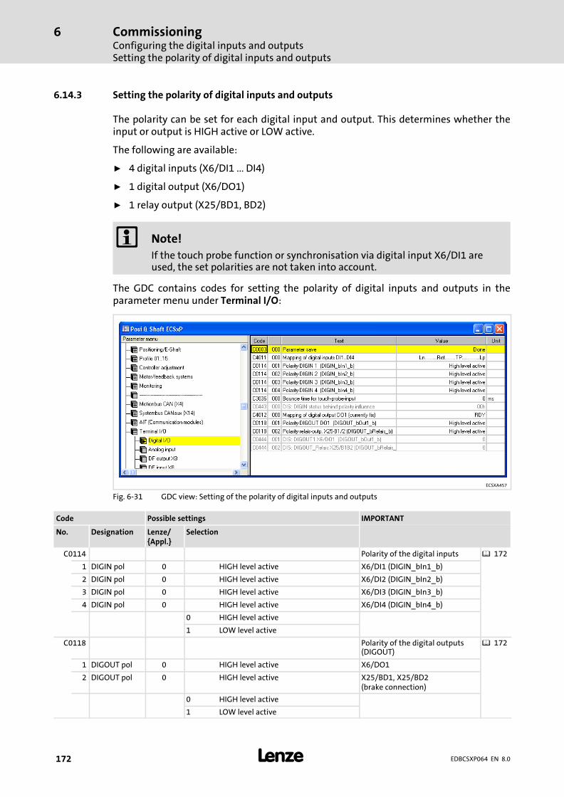
CommissioningConfiguring the digital inputs and outputsSetting the polarity of digital inputs and outputs
6
� 172 EDBCSXP064 EN 8.0
6.14.3 Setting the polarity of digital inputs and outputs
The polarity can be set for each digital input and output. This determines whether theinput or output is HIGH active or LOW active.
The following are available:
ƒ 4 digital inputs (X6/DI1 ... DI4)
ƒ 1 digital output (X6/DO1)
ƒ 1 relay output (X25/BD1, BD2)
� Note!
If the touch probe function or synchronisation via digital input X6/DI1 areused, the set polarities are not taken into account.
The GDC contains codes for setting the polarity of digital inputs and outputs in theparameter menu under Terminal I/O:
ECSXA457
Fig. 6−31 GDC view: Setting of the polarity of digital inputs and outputs
Code Possible settings IMPORTANT
No. Designation Lenze/{Appl.}
Selection
C0114 Polarity of the digital inputs � 172
1 DIGIN pol 0 HIGH level active X6/DI1 (DIGIN_bIn1_b)
2 DIGIN pol 0 HIGH level active X6/DI2 (DIGIN_bIn2_b)
3 DIGIN pol 0 HIGH level active X6/DI3 (DIGIN_bIn3_b)
4 DIGIN pol 0 HIGH level active X6/DI4 (DIGIN_bIn4_b)
0 HIGH level active
1 LOW level active
C0118 Polarity of the digital outputs(DIGOUT)
� 172
1 DIGOUT pol 0 HIGH level active X6/DO1
2 DIGOUT pol 0 HIGH level active X25/BD1, X25/BD2(brake connection)
0 HIGH level active
1 LOW level active

CommissioningSetting of manual control parameters
6
� 173EDBCSXP064 EN 8.0
6.15 Setting of manual control parameters
� Stop!
Machine parts can be damaged or destroyed!
The drive can travel into a mechanical limit during manual jog if
ƒ no reference is known (status bit Stat1.HomePosAvailable = 0, � 161).
ƒ no software limit positions are set ( 237).
The "manual jog" function is used to run the drive in inching mode, e. g. for cleaning orchanging the tool. The function is activated by setting the control bits Ctrl1.JogCW = 1 orCtrl1.JogCCW = 1 (� 158).
The control signals for "manual jog" can be linked to the digital input terminals to activatethe manual jog, for instance, via pushbuttons (� 168).
The GDC includes the codes for setting the manual control parameters in the parametermenu under Positioning/E−Shaft�� Manual jog.
ECSXA446
Fig. 6−32 GDC view: Short setup − entry of manual control parameters
Code Possible settings IMPORTANT
No. Designation Lenze/{Appl.}
Selection
C3020 ManualVel 360.0 Traversing speed for manual jog(inching mode)
� 173
0.0001 {0.0001units/s}
214000.0000
C3021 ManualAcc 720.0 Acceleration for manual jog(inching mode)
� 173
0.0001 {0.0001units/s2}
214000.0000
C3022 ManualDec 720.0 Deceleration for manual jog(inching mode)
� 173
0.0001 {0.0001units/s2}
214000.0000

CommissioningSetting of manual control parameters
6
� 174 EDBCSXP064 EN 8.0
IMPORTANTPossible settingsCode
SelectionLenze/{Appl.}
DesignationNo.
C3060 Max forC1240
Nmax (C0011) converted fromrpm to units/s based on themachine parameters C1202,C1203 and C1204.The speed indicated here is themax. possible machine speeddue to the set machineparameters and the maximumspeed nmax.Thus, the setting of themaximum machine speed(Vmax) under C1240 is onlysensible up to this amount.
� 173
0 {1 units/s} 4294960000
CommissioningSetting of manual control parameters
Manual control to software limit position
6
� 175EDBCSXP064 EN 8.0
6.15.1 Manual control to software limit position
ƒ When the home position is known (status bit Stat1.HomePosAvailable = 1) and thepositive software limit position C3040 is set to ≠ 0 and the negative software limitposition C3041 is set to ≠ 0, manual positioning is carried out on the correspondingsoftware limit position:
– The drive brakes to the position of the corresponding software limit position withthe manual deceleration set (C3022), and the warning 2403 ("NegPosLimit") or2402 ("PosPosLimit") is displayed.
– In C4046, status bit Stat2.SwLimErr is set to 1.
– This ensures that the software limit positions set cannot be passed in the"ManualJog" state when the home position is known.
ƒ By resetting control bits Ctrl1.JogCW or Ctrl1.JogCCW to "0", manual jog is stopped:
– The drive decelerates to standstill with the corresponding manual setting (C3022).
6.15.2 Manual control to hardware limit switch
If a hardware limit switch is approached during manual jog, the drive brakes to standstillvia the QSP deceleration time set (C0105).
ƒ FAIL−QSP 3401 ("NegLimitSw") or 3400 ("PosLimitSw") is displayed.
ƒ The drive changes to the "Trouble" state.
ƒ The display of the current actual position (C3051) is limited to �214000.0000 units. Ifthe maximum displayable position value is exceeded, the position display C3051remains on the maximum value of �214000.0000 units.

CommissioningSetting of manual control parametersRetracting from hardware limit switches
6
� 176 EDBCSXP064 EN 8.0
6.15.3 Retracting from hardware limit switches
� Note!
Retracting from a hardware limit switch is only possible if the limit switch isstill activated.
Ensure by the trigger mechanics that an approached hardware limit switchremains activated as long as the drive is outside the permissible travel range.
The two hardware limit switches must not be activated at the same time.Otherwise it is not possible to detect the traversing direction for retracting.
By setting the control bit Ctrl1.RelLimSwitch = 1, retracting from an active hardware limitswitch is possible by travelling in the corresponding retracting direction until the limitswitch is not active anymore.
ƒ Positive hardware limit switch approached:
– Retracting in negative direction until the positive limit switch is not activeanymore.
ƒ Negative hardware limit switch approached:
– Retracting in positive direction until the negative limit switch is not activeanymore.

CommissioningSetting of homing parameters
6
� 177EDBCSXP064 EN 8.0
6.16 Setting of homing parameters
During homing the drive travels in the selected mode (C3010) to detect the referenceposition on its own by means of a reference mark. All position data refer to this referenceposition.
The "referencing" function is selected in the positioning profile with C3095/x (� 191).The following selections are possible:
ƒ Homing (C3095/x = 100)
– Homing is mainly used for systems with feedback via incremental encoders,resolvers or single−turn absolute value encoders, where the home position getslost when the supply voltage is switched off.
ƒ Reference setting (C3095/x = 101)
– A reference is generally set only once during the commissioning or in case ofservice (e. g. when drive components are replaced) and is mainly applied insystems with feedback via absolute value encoders.
ƒ Reset the reference (C3095/x = 102)
– The "Reference known" state is reset.
The GDC contains the codes for setting the homing parameters (homing mode), speed,acceleration etc.) in the parameter menu under Positioning/E−Shaft� Homing.
ECSXA444
Fig. 6−33 GDC view: Short setup, entry of homing parameters
Code Possible settings IMPORTANT
No. Designation Lenze/{Appl.}
Selection
C3008 HomeMlim 10.0 Torque limit value for homingmode C3010 = 14 or 15 (homingto mechanical limit stop)100 % = maximum torque fromC0057
0.00 {0.01 %} 100.00
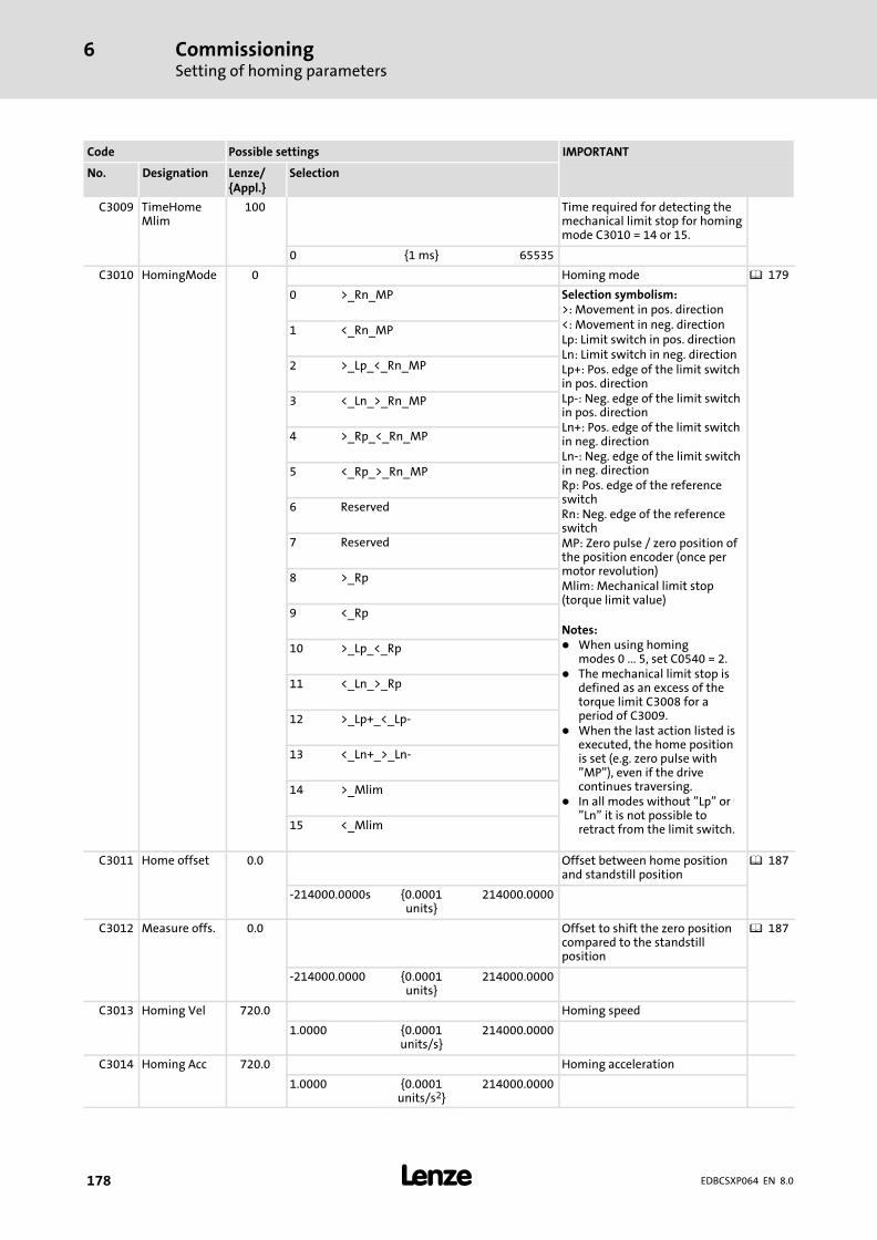
CommissioningSetting of homing parameters
6
� 178 EDBCSXP064 EN 8.0
IMPORTANTPossible settingsCode
SelectionLenze/{Appl.}
DesignationNo.
C3009 TimeHomeMlim
100 Time required for detecting themechanical limit stop for homingmode C3010 = 14 or 15.
0 {1 ms} 65535
C3010 HomingMode 0 Homing mode � 179
0 >_Rn_MP Selection symbolism:>: Movement in pos. direction<: Movement in neg. directionLp: Limit switch in pos. directionLn: Limit switch in neg. directionLp+: Pos. edge of the limit switchin pos. directionLp−: Neg. edge of the limit switchin pos. directionLn+: Pos. edge of the limit switchin neg. directionLn−: Neg. edge of the limit switchin neg. directionRp: Pos. edge of the referenceswitchRn: Neg. edge of the referenceswitchMP: Zero pulse / zero position ofthe position encoder (once permotor revolution)Mlim: Mechanical limit stop(torque limit value)
Notes:� When using homing
modes 0 ... 5, set C0540 = 2.� The mechanical limit stop is
defined as an excess of thetorque limit C3008 for aperiod of C3009.
� When the last action listed isexecuted, the home positionis set (e.g. zero pulse with"MP"), even if the drivecontinues traversing.
� In all modes without "Lp" or"Ln" it is not possible toretract from the limit switch.
1 <_Rn_MP
2 >_Lp_<_Rn_MP
3 <_Ln_>_Rn_MP
4 >_Rp_<_Rn_MP
5 <_Rp_>_Rn_MP
6 Reserved
7 Reserved
8 >_Rp
9 <_Rp
10 >_Lp_<_Rp
11 <_Ln_>_Rp
12 >_Lp+_<_Lp−
13 <_Ln+_>_Ln−
14 >_Mlim
15 <_Mlim
C3011 Home offset 0.0 Offset between home positionand standstill position
� 187
−214000.0000s {0.0001units}
214000.0000
C3012 Measure offs. 0.0 Offset to shift the zero positioncompared to the standstillposition
� 187
−214000.0000 {0.0001units}
214000.0000
C3013 Homing Vel 720.0 Homing speed
1.0000 {0.0001units/s}
214000.0000
C3014 Homing Acc 720.0 Homing acceleration
1.0000 {0.0001units/s2}
214000.0000

CommissioningSetting of homing parameters
Setting homing modes
6
� 179EDBCSXP064 EN 8.0
IMPORTANTPossible settingsCode
SelectionLenze/{Appl.}
DesignationNo.
C3015 HomJerkTime 0.0 Homing − jerk time
0.000 {0.001 ms} 10.000
6.16.1 Setting homing modes
Modes 0 and 1
Travelling to zero pulse (zero position of the position encoder) via the reference switch.
Ref
��
�
�
�
R
�
ECSXA510
Fig. 6−34 Homing in mode 0
Negative hardware limit switch� Reference switch� Zero pulse (zero position of the position encoder)� Positive hardware limit switch� Load (e. g. slide)� Direction of travel� Home position
The load (e. g. slide) travels from its starting position beyond the reference switch to thefirst zero pulse after leaving the reference switch. This zero pulse bears the home position.Before homing, the load may be positioned on the reference switch.
Settings
Mode 0(Homing in positive direction)
Mode 1(Homing in negative direction)
� Set C0540 = 2.� Set C3010 = 0.
� Set C0540 = 2.� Set C3010 = 1.
� Note!
ƒ Single−turn absolute value encoder (SinCos encoder) and resolver do nothave a zero pulse. Here the zero position corresponds to the zero pulse.
ƒ For multi−turn absolute value encoders only homing modes 8 ... 15 can beused (C3010 = 8 ... 15).

CommissioningSetting of homing parametersSetting homing modes
6
� 180 EDBCSXP064 EN 8.0
Modes 2 and 3
Approaching the hardware limit switch, reversing the direction of travel and travelling tothe zero position (zero position of the position encoder) via the reference switch.
� Note!
ƒ While reversing, the approached hardware limit switch must be assigned(mechanics must be designed accordingly).
ƒ In a 6 ms cycle, the rising edges of the hardware limit switches are queried.
Ref
�
�
R
�
�
�
�
ECSXA511
Fig. 6−35 Homing in mode 2
Negative hardware limit switch� Zero pulse (zero position of the position encoder)� Reference switch� Falling edge of the positive hardware limit switch (query in 6 ms cycle)� Load (e. g. slide)� Direction of travel� Home position
The load (e.g. slide) from its initial position is traversed to a hardware limit switch. Duringthis process, no fault message is actuated. According to the direction of travel, a reversaltakes place at the hardware limit switch approached, and, after leaving the referenceswitch, it is traversed to the first zero pulse beyond the reference switch. This zero pulsebears the home position. If the drive has already approached a hardware limit switchbefore homing, the direction of travel is reversed immediately.
In homing modes 2 and 3 the reference switch is found in any case, independent of theinitial position, as in the worst case the entire travel range is executed.

CommissioningSetting of homing parameters
Setting homing modes
6
� 181EDBCSXP064 EN 8.0
Settings
Mode 2(Homing in positive direction)
Mode 3(Homing in negative direction)
� Set C0540 = 2.� Set C3010 = 2.
� Set C0540 = 2.� Set C3010 = 3.
Variant(positive hardware limit switch = reference switch)
Variant(negative hardware limit switch = reference switch)
Additionally� connect the positive hardware limit switch parallel
to X6/DI2 and X6/DI4.� Set C0114/2 = 1. (X6/DI2 is LOW−level active.)
Additionally� Connect the negative hardware limit switch parallel
to X6/DI1 and X6/DI2.� Set C0114/2 = 1. (X6/DI2 is LOW−level active.)
� Note!
ƒ Single−turn absolute value encoder (SinCos encoder) and resolver do nothave a zero pulse. Here the zero position corresponds to the zero pulse.
ƒ For multi−turn absolute value encoders only homing modes 8 ... 15 can beused (C3010 = 8 ... 15).
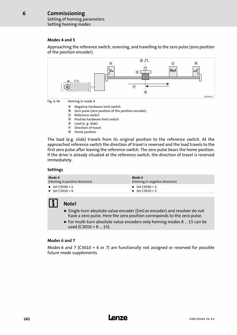
CommissioningSetting of homing parametersSetting homing modes
6
� 182 EDBCSXP064 EN 8.0
Modes 4 and 5
Approaching the reference switch, reversing, and travelling to the zero pulse (zero positionof the position encoder).
Ref
�
�
R
�
�
�
�
ECSXA512
Fig. 6−36 Homing in mode 4
Negative hardware limit switch� Zero pulse (zero position of the position encoder)� Reference switch� Positive hardware limit switch� Load (e. g. slide)� Direction of travel� Home position
The load (e.g. slide) travels from its original position to the reference switch. At theapproached reference switch the direction of travel is reversed and the load travels to thefirst zero pulse after leaving the reference switch. The zero pulse bears the home position.If the drive is already situated at the reference switch, the direction of travel is reversedimmediately.
Settings
Mode 4(Homing in positive direction)
Mode 5(Homing in negative direction)
� Set C0540 = 2.� Set C3010 = 4.
� Set C0540 = 2.� Set C3010 = 5.
� Note!
ƒ Single−turn absolute value encoder (SinCos encoder) and resolver do nothave a zero pulse. Here the zero position corresponds to the zero pulse.
ƒ For multi−turn absolute value encoders only homing modes 8 ... 15 can beused (C3010 = 8 ... 15).
Modes 6 and 7
Modes 6 and 7 (C3010 = 6 or 7) are functionally not assigned or reserved for possiblefuture mode supplements.
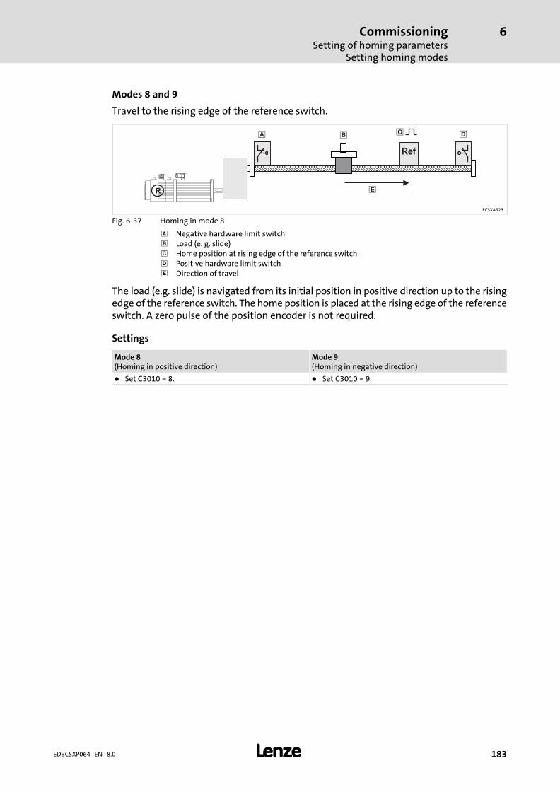
CommissioningSetting of homing parameters
Setting homing modes
6
� 183EDBCSXP064 EN 8.0
Modes 8 and 9
Travel to the rising edge of the reference switch.
Ref
� �
R �
� �
ECSXA523
Fig. 6−37 Homing in mode 8
Negative hardware limit switch� Load (e. g. slide)� Home position at rising edge of the reference switch� Positive hardware limit switch� Direction of travel
The load (e.g. slide) is navigated from its initial position in positive direction up to the risingedge of the reference switch. The home position is placed at the rising edge of the referenceswitch. A zero pulse of the position encoder is not required.
Settings
Mode 8(Homing in positive direction)
Mode 9(Homing in negative direction)
� Set C3010 = 8. � Set C3010 = 9.

CommissioningSetting of homing parametersSetting homing modes
6
� 184 EDBCSXP064 EN 8.0
Modes 10 and 11
Approach hardware limit switch, reverse and navigate to the rising edge of the referenceswitch.
� Note!
ƒ While reversing, the approached hardware limit switch must be assigned(mechanics must be designed accordingly).
ƒ In a 6 ms cycle, it is queried whether the hardware limit switch is assigned.
Ref
�R
�
�
��
ECSXA524
Fig. 6−38 Homing in mode 10
Negative hardware limit switch� Home position at rising edge of the reference switch� Falling edge of the positive hardware limit switch (query in 6 ms cycle)� Load (e. g. slide)� Direction of travel
The load (e.g. slide) is navigated from its initial position to a hardware limit switch. Therebyno fault message is triggered. According to the direction of travel, a reversal takes place atthe hardware limit switch approached and then the reference switch is approached. Thehome position is placed a the rising edge of the reference switch. A zero pulse of theposition encoder is not required.
Settings
Mode 10(Homing in positive direction)
Mode 11(Homing in negative direction)
� Set C3010 = 10. � Set C3010 = 11.
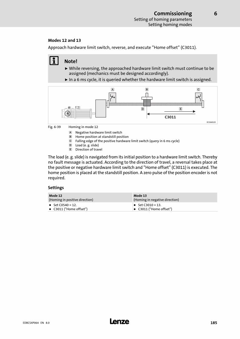
CommissioningSetting of homing parameters
Setting homing modes
6
� 185EDBCSXP064 EN 8.0
Modes 12 and 13
Approach hardware limit switch, reverse, and execute "Home offset" (C3011).
� Note!
ƒ While reversing, the approached hardware limit switch must continue to beassigned (mechanics must be designed accordingly).
ƒ In a 6 ms cycle, it is queried whether the hardware limit switch is assigned.
�
�R
�
�
�
C3011
ECSXA525
Fig. 6−39 Homing in mode 12
Negative hardware limit switch� Home position at standstill position� Falling edge of the positive hardware limit switch (query in 6 ms cycle)� Load (e. g. slide)� Direction of travel
The load (e. g. slide) is navigated from its initial position to a hardware limit switch. Therebyno fault message is actuated. According to the direction of travel, a reversal takes place atthe positive or negative hardware limit switch and "Home offset" (C3011) is executed. Thehome position is placed at the standstill position. A zero pulse of the position encoder is notrequired.
Settings
Mode 12(Homing in positive direction)
Mode 13(Homing in negative direction)
� Set C0540 = 12.� C3011 ("Home offset")
� Set C3010 = 13.� C3011 ("Home offset")

CommissioningSetting of homing parametersSetting homing modes
6
� 186 EDBCSXP064 EN 8.0
Modes 14 and 15
Approach mechanical limit stop and set home position.
�
�R
��
�ECSXA521
Fig. 6−40 Homing in mode 14
Mechanical limit stop (negative)� Load (e. g. slide)� Mechanical limit stop (positive)� Direction of travel� Home position
The load (e. g. slide) is navigated in positive or negative direction to the mechanical limitstop from its initial position. For the duration of the homing, the motor torque is limitedto the torque limit value (C3008). If the motor torque reaches the torque limit value or atime that is longer than the time defined in C3009, the internal speed setpoint is traversedto "0" with the homing acceleration (C3014). If the internal speed setpoint is 0, the homeposition is set in this position and homing is completed.
C3009
C4018100 % Mmax
C3008
Stat1.HomePosAvailable
1
v
t
t
t
M
��
�
�
ECSXP005
Fig. 6−41 Procedure of the homing in modes 14/15
Actual speed value� Speed setpoint� Mechanical limit stop� Actual torque
Settings
Mode 14(Homing in positive direction)
Mode 15(Homing in negative direction)
� Set C3010 = 14. � Set C3010 = 15.

CommissioningSetting of homing parameters
Shifting the zero position with regard to the home position (offsets C3011, C3012)
6
� 187EDBCSXP064 EN 8.0
6.16.2 Shifting the zero position with regard to the home position (offsets C3011, C3012)
�
C3011
Ref
�
��
C3012�
0
v [m/s]
t [s]
ECSXA437
Fig. 6−42 Offset of the zero position (note: Different behaviour of ECS Motion and ECS Posi&Shaft)
, � Negative and positive hardware limit switch� Home position (zero pulse/zero position of the position encoder)� Standstill position after completion of homing� Zero position of the measuring system after offset by C3011 and C3012REF Reference switch
Offset between home position and standstill position (C3011)
ƒ Distance to be traversed after the home position has been reached (zero pulse/zeroposition of the position encoder).
ƒ Positive values cause a drive movement in the direction of the positive hardwarelimit switch, negative values cause the opposite direction.
Offset to shift the zero position compared to the standstill position (C3012):
ƒ The zero position is only offset in terms of figures without moving the drive: Zeroposition = standstill position − C3012
ƒ With positive values, the zero position is offset in negative direction.
ƒ The actual position is set to the value C3012. This leads to the offset of the zeroposition.
� Note!
When the zero position is shifted by C3011 and C3012, the software limitpositions (C3040, C3041) are shifted as well towards the mechanicalcomponents. Therefore adapt the software limit positions (� 237)accordingly.
Code Possible settings IMPORTANT
No. Designation Lenze/{Appl.}
Selection
C3011 Home offset 0.0 Offset between home positionand standstill position
� 187
−214000.0000s {0.0001units}
214000.0000

CommissioningSetting of homing parametersExample: Reference search with linear positioning axis
6
� 188 EDBCSXP064 EN 8.0
IMPORTANTPossible settingsCode
SelectionLenze/{Appl.}
DesignationNo.
C3012 Measure offs. 0.0 Offset to shift the zero positioncompared to the standstillposition
� 187
−214000.0000 {0.0001units}
214000.0000
6.16.3 Example: Reference search with linear positioning axis
Settings for homing mode 3
ƒ Set homing mode 3 with C3010 = 3.
ƒ The negative hardware limit switch at the same time is to be used as a homingswitch.
– Connect hardware limit switch in parallel with X6/DI1 and X6/DI2.(For terminalassignment see � 172)
– Set C0114/1 and C0114/2 = 1 (LOW level is active).
ƒ Define homing speed via C3013.
ƒ Define acceleration/deceleration via C3014.
ƒ Define target position as offset to the home position via C3011.
�
�
� �
�
C3011
100 200 300 400 500 600
ECSXA435
Fig. 6−43 Homing in mode 3, negative hardware limit switch as reference switch
Negative hardware limit switch� Travel to limit switch (= reference switch) and reverse there� From zero pulse travel via the defined offset (C3011) towards target position� Positive hardware limit switch� Zero pulse (zero position of the position encoder)� Target position
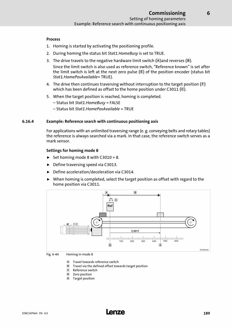
CommissioningSetting of homing parameters
Example: Reference search with continuous positioning axis
6
� 189EDBCSXP064 EN 8.0
Process
1. Homing is started by activating the positioning profile.
2. During homing the status bit Stat1.HomeBusy is set to TRUE.
3. The drive travels to the negative hardware limit switch ( )and reverses (�).
Since the limit switch is also used as reference switch, "Reference known" is set afterthe limit switch is left at the next zero pulse (�) of the position encoder (status bitStat1.HomePosAvailable= TRUE).
4. The drive then continues traversing without interruption to the target position (�)which has been defined as offset to the home position under C3011 (�).
5. When the target position is reached, homing is completed.
– Status bit Stat1.HomeBusy = FALSE
– Status bit Stat1.HomePosAvailable = TRUE
6.16.4 Example: Reference search with continuous positioning axis
For applications with an unlimited traversing range (e. g. conveying belts and rotary tables)the reference is always searched via a mark. In that case, the reference switch serves as amark sensor.
Settings for homing mode 8
ƒ Set homing mode 8 with C3010 = 8.
ƒ Define traversing speed via C3013.
ƒ Define acceleration/deceleration via C3014.
ƒ When homing is completed, select the target position as offset with regard to thehome position via C3011.
C3011
100 200 300 400 500 600
Ref
�
��
�
�
ECSXA434
Fig. 6−44 Homing in mode 8
Travel towards reference switch� Travel via the defined offset towards target position� Reference switch� Zero position� Target position
CommissioningSetting of homing parametersExample: Reference search with continuous positioning axis
6
� 190 EDBCSXP064 EN 8.0
Process
1. Homing is started by activating the positioning profile.
2. During homing the status bit Stat1.HomeBusy is set to TRUE.
3. The drive travels in positive direction ( ).
Mit Erreichen der steigenden Flanke des Referenzschalters (�) ist derAntriebssteuerung die Referenz bekannt.
4. The drive continues traversing without interruption to the target position (�) whichhas been defined as offset to the home position under C3011 (�).
5. When the target position is reached, homing is completed.
– Status bit Stat1.HomeBusy = FALSE
– Status bit Stat1.HomePosAvailable = TRUE

CommissioningSetting the positioning profile
Selecting a positioning profile mode
6
� 191EDBCSXP064 EN 8.0
6.17 Setting the positioning profile
Up to 15 positioning profiles can be set in the ECSxP axis module to execute the differentpositioning tasks required for a machine.
For setting a positioning profile, carry out the following steps:
ƒ Select the positioning profile mode via C3095. ( 191)
ƒ Set positioning profile parameters. ( 201)
ƒ Configure the additional functions of the positioning profile. ( 204)
The Global Drive Control (GDC) contains the corresponding codes in the parameter menuunder Profile 01..15.
ECSXA445
Fig. 6−45 GDC view: Setting of positioning profiles
6.17.1 Selecting a positioning profile mode
� Note!
ƒ The target position in C3100 must be between the positive and negativevalue from C4265 (max. target position selection).– Example: C4265 = 10000 C3100 = −10000 ... +10000
ƒ The maximum traversing range amounts to 2147483649 increments for allpositioning profile modes (231 − 1).
ƒ The position display C3051 is limited to ± 214000,0000 units.
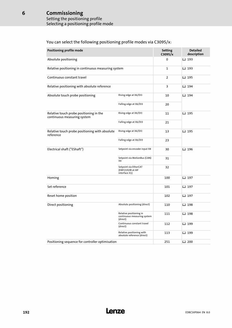
CommissioningSetting the positioning profileSelecting a positioning profile mode
6
� 192 EDBCSXP064 EN 8.0
You can select the following positioning profile modes via C3095/x:
Positioning profile mode SettingC3095/x
Detaileddescription
Absolute positioning 0 � 193
Relative positioning in continuous measuring system 1 � 193
Continuous constant travel 2 � 195
Relative positioning with absolute reference 3 � 194
Absolute touch probe positioning Rising edge at X6/DI3 10 � 194
Falling edge at X6/DI3 20
Relative touch probe positioning in thecontinuous measuring system
Rising edge at X6/DI3 11 � 195
Falling edge at X6/DI3 21
Relative touch probe positioning with absolutereference
Rising edge at X6/DI3 13 � 195
Falling edge at X6/DI3 23
Electrical shaft ("EShaft") Setpoint via encoder input X8 30 � 196
Setpoint via MotionBus (CAN)X4
31
Setpoint via EtherCAT(EMF2192IB at AIFinterface X1)
32
Homing 100 � 197
Set reference 101 � 197
Reset home position 102 � 197
Direct positioning Absolute positioning (direct) 110 � 198
Relative positioning incontinuous measuring system(direct)
111 � 198
Continuous constant travel(direct)
112 � 199
Relative positioning withabsolute reference (direct)
113 � 199
Positioning sequence for controller optimisation 251 � 200

CommissioningSetting the positioning profile
"Point−to−point" positioning
6
� 193EDBCSXP064 EN 8.0
6.17.2 "Point−to−point" positioning
6.17.2.1 Absolute positioning
Application: axes with a limited traversing range (e. g. palletizers)
C3095/x = 0
ƒ The drive carries out a "point−to−point" positioning in the absolute measuringsystem.
ƒ The target position is defined as definite absolute position with regard to the zeroposition of the measuring system. The distance to be travelled results from thedistance between the actual position and the absolute target position.
Preconditions
ƒ The drive must be referenced (status bit Stat1.HomePosAvailable = 1).
6.17.2.2 Relative positioning in the continuous measuring system
C3095/x = 1
ƒ The drive carries out a relative "point−to−point" positioning in the continuousmeasuring system (incremental dimension).
Application: roll feed
ƒ The defined target position corresponds to the distance to be travelled. Thus, thedrive continues to travel by exactly the defined distance from the current positionon.
Before positioning is started, the path integrators are reset in the continuousmeasuring system. The following error, however, remains stored in order that no jerkoccurs in the drive.
ƒ Status bit Stat1.HomePosAvailable is reset.
Preconditions
ƒ No homing required.
CommissioningSetting the positioning profileTouch probe positioning
6
� 194 EDBCSXP064 EN 8.0
6.17.2.3 Relative positioning with absolute reference
C3095/x = 3
ƒ The drive carries out a relative "point−to−point" positioning in the absolutemeasuring system.
Application: Feed by a given distance in case of axes with limited traversing range
ƒ The target position defined via the profile parameters corresponds to the distance tobe travelled (as in the continuous measuring system). Thus, the drive travels exactlyby the defined distance (target position) from the current position on, but the pathintegrators are not reset before.
The absolute target position to be approached results from the last absolute targetposition plus the distance defined as profile parameters (target position).
Preconditions
ƒ The drive must be referenced (status bit Stat1.HomePosAvailable = 1).
6.17.3 Touch probe positioning
Touch probe positioning is used if the exact target position to be approached is not knownyet but can only be determined by a mark signal of the machine or the product.
Process of TP positioning:
ƒ TP positioning always consists of two successive positioning profiles.
Only the profile numbers 1 ... 14 may be used as the first TP profile so that a sequenceprofile is still available!
ƒ In the first TP positioning, it is first travelled to a provisional target position. Duringthis motion, the TP input (X6/DI3) is active.
Only after the touch probe sensor responds during operation, the final target positionis calculated in the sequence profile (profile number +1) and approached without stop.
ƒ The final target position is calculated from the TP position plus the target position ofthe sequence profile which is evaluated as relative distance (residual path). The signof the residual path determines the traversing direction.
Example: With a negative traversing direction in the first TP profile and a positiveresidual path, the drive would reverse. The positioning profile mode (C3095/x) of thesequence profile is ignored.
ƒ Different TP positioning types can be set under the profile mode C3095/x. Theydiffer in the first positioning type and the edge of the TP signal is set.
6.17.3.1 Absolute TP positioning
C3095/x = 10 or 20
ƒ The first TP positioning to the provisional target position is executed the same wayas is the case with absolute positioning. The same conditions apply ( 193).
ƒ Edge selection of TP input:
– C3095/x = 10: positive edge at TP input X6/DI3
– C3095/x = 20: negative edge at TP input X6/DI3
CommissioningSetting the positioning profile
Continuous constant travel
6
� 195EDBCSXP064 EN 8.0
6.17.3.2 Relative TP positioning in the continuous measuring system
C3095/x = 11 or 21
ƒ The first TP positioning to the provisional target position is executed the same wayas is the case with relative positioning in the continuous measuring system. Thesame conditions apply ( 193).
ƒ Edge selection of TP input:
– C3095/x = 11: positive edge at input X6/DI3
– C3095/x = 21: negative edge at input X6/DI3
6.17.3.3 Relative TP positioning with absolute reference
C3095/x = 13 or 23
ƒ The first TP positioning to the provisional target position is executed the same wayas is the case with relative positioning with absolute reference. The same conditionsapply ( 194).
ƒ Edge selection of TP input:
– C3095/x = 11: positive edge at input X6/DI3
– C3095/x = 21: negative edge at input X6/DI3
6.17.4 Continuous constant travel
C3095/x = 2
ƒ The drive travels with constant speed according to the speed selection as long as theprofile is active.
ƒ The target position selection is ignored.
ƒ The positioning parameters (� 201) are defined in the positioning profile.
ƒ Stop of the constant travel by aborting the profile by the control bitCtrl1.ProfEnable = 0 or, if "Direct Change" is active, by selecting another profilenumber.
ƒ The software limit positions are monitored when homing is executed and thus thereference is known (status bit Stat1.HomePosAvailable = 1).
Preconditions
ƒ No homing required!
ƒ The 32−bit display area of �(231 − 1) internal increments can be overtravelled withoutstopping the drive if ...
– homing has not been executed before (status bit Stat1.HomePosAvailable = 0) or
– the software limit positions are deactivated (setting 0 units).
ƒ When the range limit is overtravelled, the actual value jumps by 232 increments andthe warning 2423 ("OverflIntPos", position setpoint overflow) is displayed.
CommissioningSetting the positioning profileElectrical shaft ("E−shaft") per digital frequency, MotionBs (CAN) or EtherCAT
6
� 196 EDBCSXP064 EN 8.0
6.17.5 Electrical shaft ("E−shaft") per digital frequency, MotionBs (CAN) or EtherCAT
C3095/x = 30, 31 or 32
ƒ The drive performs a ratio synchronisation.
ƒ C3095/x = 30:
"Electrical shaft" with setpoint selection via digital frequency input X8 via TTLrectangular differential signal.
Setting sequence see � 215.
ƒ C3095/x = 31:
"Electrical shaft" with setpoint selection via the process data channel of the MotionBus(CAN) X4. The master value is defined as 32−bit angle setpoint at X4 (CAN, Rx−PDO2).
– Definition as DWORD (word3/4)
– Scaling: 216 inc/rev (motor)
Activate the control program synchronization via CAN sync telegram.
Setting sequence see � 217 159.
ƒ C3095/x = 32:
"Electrical shaft" with setpoint selection via the process data channel of theEMF2192IB EtherCAT communication module at the AIF interface (X1). The mastervalue is defined as 32−bit angle setpoint at X1 (AIF, Rx−PDO1).
– Definition as DWORD (word3/4)
– Scaling: 216 inc/rev (motor)
Activate the control program synchronization via EtherCAT sync telegram.
Setting sequence see � 224.
ƒ The stretch factor for setting the ratio between master and slave drive is defined asnumerator (C3097) / denominator (C3 098):
– Permissible value range C3097: −32767 ... +32767
– Negative values cause a reversal of the rotation direction.
– Permissible value range C3098: 1 ... 32760
ƒ The stretch factor can be changed during the running positioning profile.
ƒ The machine parameters for the gearbox ratio (C1202/C1203, � 103) only have aneffect on positioning and have no impact on the "electrical shaft" drive function.
ƒ No ramps are created. Therefore it is only reasonable to activate/deactivate thefunction when the master value encoder is at standstill.
ƒ The following errors are switched off at the limit value (C3031).
ƒ In case of an exceedance of the following error warning tolerance C3030, thewarning "FollowErrWarn" will be enabled. The status bit Stat2.FollowErrWarn will beset to "1" (TRUE).
ƒ In case of a known reference (status bit Stat1.HomePosAvailable = 1), the softwarelimit switches will be monitored.
ƒ The compensation of speed−proportional angular offsets is effected via C4060.
CommissioningSetting the positioning profile
Homing
6
� 197EDBCSXP064 EN 8.0
6.17.6 Homing
6.17.6.1 Homing
C3095/x = 100
ƒ Homing is carried out according to the selected homing mode ( 179).
ƒ For homing parameters see � 177.
ƒ The status bit Stat1.HomePosAvailable is set to "1" after a successful execution(monitoring of the software limit positions is activated).
6.17.6.2 Setting the reference
C3095/x = 101
ƒ The current position is stored as the home position and used as the measuringsystem reference.
ƒ The drive does not move.
ƒ The status bit Stat1.HomePosAvailable is set to "1" (monitoring of the software limitposition is activated).
ƒ In case of feedback system of type AM:
– When the reference is set, the controller must be inhibited (Ctrl1.Cinh = 1).
– The home position is maintained after switching off and on again the controlvoltage of the drive.
Preconditions
ƒ Status bit Stat1.HomePosAvailable = 0; if required, execute the "Reset reference"function first (see below).
6.17.6.3 Reset reference (Reset HomePosAvailable)
C3095/x = 102
ƒ The reference of the measuring system to the home position is cancelled.
ƒ The status bit Stat1.HomePosAvailable is set to "0" (monitoring of the software limitposition is deactivated).
CommissioningSetting the positioning profileDirect positioning
6
� 198 EDBCSXP064 EN 8.0
6.17.7 Direct positioning
6.17.7.1 Absolute positioning (direct)
C3095/x = 110
Positioning is executed the same way as it is the case with absolute positioning ( 193),with the following differences:
ƒ The position selection is carried out in the process data telegram via "PosDirect" inincrements (65536 incr. = 1 motor revolution).
ƒ The speed selection is effected in the process data telegram via "VelDirect" inpercent [%] of the maximum speed (vmax) from C3060.
(VelDirect = 16384 = 100 % vmax.)
ƒ The other positioning parameters (� 201) are defined in the positioning profile.
Preconditions
ƒ Status bit Stat1.HomePosAvailable = 1
ƒ Control bit Ctrl1.PosDirect = 1 (selection of direct positioning)
ƒ From software version V2.0, the control bit Ctrl1.PosDirect is redundant. Thus, thereis no need for it anymore to be set as precondition for the direct positioning.
6.17.7.2 Relative positioning in the continuous measuring system (direct)
C3095/x = 111
ƒ Positioning is executed the same way as it is the case with relative positioning in thecontinuous measuring system ( 193), with the following differences:
ƒ The position selection is carried out in the process data telegram via "PosDirect" inincrements (65536 incr. = 1 motor revolution).
ƒ The speed selection is effected in the process data telegram via "VelDirect" inpercent [%] of the maximum speed (vmax) from C3060.
(VelDirect = 16384 = 100 % vmax.)
ƒ The other positioning parameters (� 201) are defined in the positioning profile.
ƒ Status bit Stat1.HomePosAvailable is reset.
Preconditions
ƒ No homing required!
ƒ Control bit Ctrl1.PosDirect = 1 (selection of direct positioning)
ƒ The path integrators are reset before the start.
CommissioningSetting the positioning profile
Direct positioning
6
� 199EDBCSXP064 EN 8.0
6.17.7.3 Continuous constant travel (direct)
C3095/x = 112
ƒ The drive performs a constant travel as long as the function is active.
ƒ The target position selection is ignored.
ƒ The speed selection is effected in the process data telegram via "VelDirect" inpercent [%] of the maximum speed (vmax) from C3060.
(VelDirect = 16384 = 100 % vmax.)
ƒ The other positioning parameters (� 201) are defined in the positioning profile.
ƒ Abortion with control bit Ctrl1.ProfEnable = 0.
ƒ When status bit Stat1.HomePosAvailable = 1, the software limit positions aremonitored.
Preconditions
ƒ No homing required!
ƒ Control bit Ctrl1.PosDirect = 1 (selection of direct positioning)
Special feature with the "Continuous constant travel (direct)" mode and activeoverride−PDO:
When the positioning profile with "Continuous constant travel (direct)" starts, the sign ofthe PDO data word "rx_par1" determines the direction of rotation of the constant travel.The override influence itself continues to be effected according to amount.
6.17.7.4 Relative positioning with absolute reference (direct)
C3095/x = 113
ƒ Positioning is executed the same way as it is the case with relative positioning withabsolute reference ( 194), with the following differences:
ƒ The target position is defined as a relative distance with regard to the currentposition.
ƒ The position selection is carried out in the process data telegram via "PosDirect" inincrements (65536 incr. = 1 motor revolution).
ƒ The speed selection is effected in the process data telegram via "VelDirect" inpercent [%] of the maximum speed (vmax) from C3060.
(VelDirect = 16384 = 100 % vmax.)
ƒ The other positioning parameters (� 201) are defined in the positioning profile.
Preconditions
– Status bit Stat1.HomePosAvailable = 1
– Control bit Ctrl1.PosDirect = 1 (selection of direct positioning)
CommissioningSetting the positioning profilePositioning sequence for controller optimisation
6
� 200 EDBCSXP064 EN 8.0
6.17.8 Positioning sequence for controller optimisation
C3095/x = 251
ƒ The drive carries out a relative "point−to−point" positioning in positive direction inthe continuous measuring system (incremental dimension). (see also modeC3095/x = 1, � 193)
ƒ With Stat1.DwellTime = 1, the target position is inverted internally and traversing iscarried out in negative direction. This process is repeated in a cyclic manner.
ƒ The positioning parameters (� 201) are defined in the positioning profile.
ƒ This positioning profile mode can be used for testing or for optimising the controlloop settings.

CommissioningSetting the positioning profile
Setting of positioning profile parameters
6
� 201EDBCSXP064 EN 8.0
6.17.9 Setting of positioning profile parameters
The target position, traversing speed, acceleration, deceleration, and jerk time for thepositioning profile parameters can be set via the following codes:
Code Possible settings IMPORTANT
No. Designation Lenze/{Appl.}
Selection
C3100 Parameter "Target position" forpositioning profiles 1 ... 15Note: Input value must be withinthe range of the � valuefrom C4265.� Example: C4265 = 10000
value range −10000 ... +10000
� 97
1 Prof.Position 0 −214000.0000 {0.0001units}
214000.0000
... ... ...
15 Prof.Position 0
C3200 Parameter "Traversing speed" forpositioning profiles 1 ... 15Note:C3063 < [input value] ≤ C3060
� 98
1 Prof.Velocity 0 −214000.0000 {0.0001units}
214000.0000
... ... ...
15 Prof.Velocity 0
C3300 Parameter "Acceleration" forpositioning profiles 1 ... 15
� 98
1 Prof.Acc 0 −0.0000 {0.0001units}
214000.0000
... ... ...
15 Prof.Acc 0
C3400 Parameter "Deceleration" forpositioning profiles 1 ... 15
� 98
1 Prof.Dec 0 −0.0000 {0.0001units}
214000.0000
... ... ...
15 Prof.Dec 0
C3500 Parameter reserved � 98
1 Prof.FinalVel 0 −214000.0000 {0.0001units}
214000.0000
... ... ...
15 Prof.FinalVel 0
C3600 Parameter "Jerk time" forpositioning profiles 1 ... 15
� 99
1 Prof.JerkTime 0 0.000 {0.001 s} 0.500
... ... ...
15 Prof.JerkTime 0
CommissioningSetting the positioning profileSetting the profile parameter jerk time for S−shaped ramps
6
� 202 EDBCSXP064 EN 8.0
6.17.10 Setting the profile parameter jerk time for S−shaped ramps
The setting of the jerk time under C3600/x serves to change over between L profile and Sprofile for generating the travel profile.
ƒ Jerk time = 0, L profile is active (Lenze setting):
The positioning profile is generated with linear ramps. All positioning profile modes(C3095/x) can be used.
ƒ Jerk time � 0, S profile is active:
The positioning profile is generated with S−shaped ramps. This ramp form cannot beused with the touch probe positioning profile modes C3095/x = 10 ... 23 and neitherwith positioning profiles with the activated additional function "Immediate profilechange" (C3096/x.Bit5 = 1).
The jerk time set under C3600/x is a measure for smoothening the speed curve withS−ramps. The jerk time corresponds to the ramp time (tjerk), after which the acceleration setin the positioning profile is reached, starting from acceleration 0.
The smoothening of the speed curve with S−ramps serves to limit the jerk and thus for aprotection of the machine mechanics.
� Note!
If disproportionately high jerk times (tjerk) are set for short acceleration phases(tacc), the profile may be generated incorrectly.
Example:
v = 100 mm/s, a = 1000 mm/s2
tacc = v / a = 0.1 s
tjerk = 0.05 s
For this reason, set only plausible jerk times for the S−ramps under C3600/x.These must not exceed half the value of tacc.
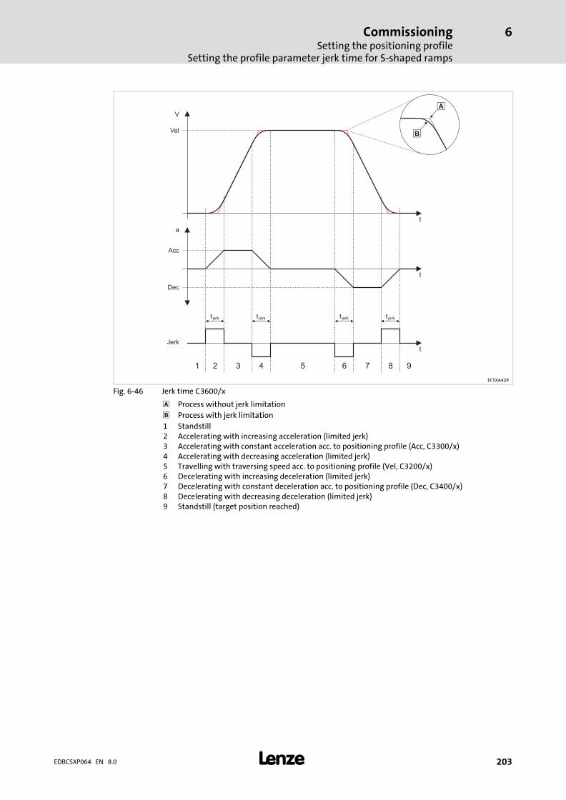
CommissioningSetting the positioning profile
Setting the profile parameter jerk time for S−shaped ramps
6
� 203EDBCSXP064 EN 8.0
V
t
t
a
tJerk
1 2 3 4 5 6 7 8 9
Vel
Acc
Dec
t jerk t jerk jerkt t jerk
�
�
ECSXA429
Fig. 6−46 Jerk time C3600/x
Process without jerk limitation
� Process with jerk limitation
1 Standstill2 Accelerating with increasing acceleration (limited jerk)3 Accelerating with constant acceleration acc. to positioning profile (Acc, C3300/x)4 Accelerating with decreasing acceleration (limited jerk)5 Travelling with traversing speed acc. to positioning profile (Vel, C3200/x)6 Decelerating with increasing deceleration (limited jerk)7 Decelerating with constant deceleration acc. to positioning profile (Dec, C3400/x)8 Decelerating with decreasing deceleration (limited jerk)9 Standstill (target position reached)

CommissioningSetting the positioning profileAdditional functions of the positioning profile (C3096/x)
6
� 204 EDBCSXP064 EN 8.0
6.17.11 Additional functions of the positioning profile (C3096/x)
The following additional positioning profile functions can be set under code C3096/x:
ƒ Activate a speed override ( 205)
– via the analog input (10 V � 100%) and/or
– by means of the process data object (PDO) via CAN, AIF, C4040.
ƒ Activate a torque limitation after positioning. ( 208)
ƒ Activate profile continuation after a profile stop. ( 209)
ƒ Activate immediate profile change during positioning. ( 210)
Code Possible settings IMPORTANT
No. Designation Lenze/{Appl.}
Selection
C3096 Additional function forpositioning profile 1 ... 15
� 204
1 Prof.Func1 0 No function Additional function forpositioning profile 1
... ... ... ... ...
15 Prof.Func1 0 No function Additional function forpositioning profile 15
0 65535 The controller interprets theinformation in bit codes (16 bits).
0000.0000.0000.0000: No function No function
xxxx.xxxx.xxxx.xxx1: Vel_Ovr_Ain Speed override is activated viaanalog input.
xxxx.xxxx.xxxx.xx1x: pos_>Mlim Torque limitation afterpositioning
xxxx.xxxx.xxxx.x1xx: ProfEnable_>Continue
Profile continuation after profilestop
xxxx.xxxx.xxxx.1xxx: Vel_Ovr_PDO Speed override is activated viaPDO "Rx_par1" (CAN, AIF,C4041).
xxxx.xxxx.xxx1.xxxx: Direct change Immediate profile change duringpositioning
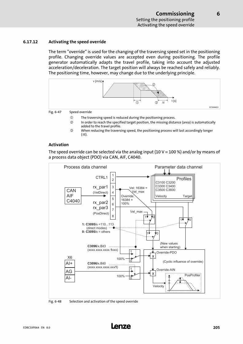
CommissioningSetting the positioning profileActivating the speed override
6
� 205EDBCSXP064 EN 8.0
6.17.12 Activating the speed override
The term "override" is used for the changing of the traversing speed set in the positioningprofile. Changing override values are accepted even during positioning. The profilegenerator automatically adapts the travel profile, taking into account the adjustedacceleration/deceleration. The target position will always be reached safely and reliably.The positioning time, however, may change due to the underlying principle.
v [m/s]
�
�
� �tt [s]
ECSXA413
Fig. 6−47 Speed override
� The traversing speed is reduced during the positioning process.
� In order to reach the specified target position, the missing distance (area) is automaticallyadded to the travel profile.
� When reducing the traversing speed, the positioning process will last accordingly longer(�t).
Activation
The speed override can be selected via the analog input (10 V � 100 %) and/or by means ofa process data object (PDO) via CAN, AIF, C4040.
� � � � � � �
� � � � � � � � � � � � � � �
� � � � �� � � � � � � �
� � � � � � � � � � � � �
� � � � � �
� � � � � �� � � � � �
� � �� � � ! " ! "
� � # $ �
"�
"�
� � � � � � � � % � � " & & & � � � ' � � � � � � � � � � (� � � � � � � � % � � � � �
"�
�"
�
� " " )
� � � � * � & + � � �' � � � � & � � � � & � � � � & � � � � (
� � � � � �
�"
�
� " " )
� � � � � & + � � "' � � � � & � � � � & � � � � & � � � � (
� � ,
- . � � � � � � / � 0 -
- . � � � � � � / � � �
- . � � � � � � 1� 2 � 3 ! %� " " )
' � � 4 . � 5 � 4 � � � � � � � � � (
' � � � � � � � � � � 5 � � � � � � � . � � � � � � (
� � � � � � � � � �� 6
� � /
7 2
�
�
�
!
8
2
9
3
� � � � � � � �
� � � " " � � � " "� � � " " � � ! " "� � 8 " " � � 2 " "
� � � 1 � 2 � 3 ! % � � � � � �' � � � 0 � � � � � (
' � � 0 � � � � � (
Fig. 6−48 Selection and activation of the speed override
CommissioningSetting the positioning profileActivating the speed override
6
� 206 EDBCSXP064 EN 8.0
6.17.12.1 Override via analog input (override−AIN)
ƒ Activation of the override AIN: C3096/x.Bit0 = 1 (xxxx.xxxx.xxxx.xxx1)
ƒ Scaling: 10 V � 16384 � 100 %
Example: Calculation of the effective speed (vreal)
ƒ Profile traversing speed (vprof) = 5000 mm/s
ƒ Override−AIN = 80 %
vreal � vprof � Override−AIN�[%] � 5000�mm�s � 80�% � 4000�mm�s
6.17.12.2 Override via process data object (override−PDO)
ƒ Activation of the override PDO: C3096/x.Bit3 = 1 (xxxx.xxxx.xxxx.1xxx)
ƒ Scaling: 16384 � 100 %
ƒ Transmission via data word "rx_par1" (VelDirect)
Example: Calculation of the effective speed (vreal)
ƒ Profile traversing speed (vprof) = 5000 mm/s
ƒ Override−PDO = 50 %
vreal � vprof � Override−PDO�[%] � 5000�mm�s � 50�% � 2500�mm�s
Direct positioning without override−PDO
ƒ Transmission:
Data word "rx_par1" (VelDirect) = profile traversing speed
(Is accepted once for the profile start.)
Direct positioning with override−PDO
ƒ Transmission:
Data word "rx_par1" (VelDirect) = override PDO
(Is accepted cyclically, also during positioning.)
vreal � Vel_max � Override−PDO�[%]
vreal effective speedVel_max maximum permissible speed (C1240)
Special feature with the "Continuous constant travel (direct)" with override−PDO:
When the "Continuous constant travel (direct)" starts, the sign of the PDO data word"rx_par1" determines the direction of rotation. The override influence itself continues tobe effected according to amount.

CommissioningSetting the positioning profileActivating the speed override
6
� 207EDBCSXP064 EN 8.0
Override−AIN and override−PDO are activated simultaneously
If override−AIN and override−PDO are activated at the same time, both override inputs areeffective (also for direct positioning).
ƒ Setting: C3096/x.Bit0 = 1 (xxxx.xxxx.xxxx.xxx1) und C3096/x.Bit3 = 1(xxxx.xxxx.xxxx.1xxx)
Example: Calculation of the effective speed (vreal)
ƒ Profile traversing speed (vprof) = 5000 mm/s
ƒ Override−AIN = 80 %
ƒ Override−PDO = 50 %
vreal � vprof � Override−AIN�[%] � Override−PDO�[%]
5000�mm�s � 80�% � 50�% � 2000�mm�s
The speed override is deactivated under the following conditions (is a byword for override= 100 %):
ƒ C3096/x.Bit0= 0 (xxxx.xxxx.xxxx.xxx0) bzw. Bit3 = 0 (xxxx.xxxx.xxxx.0xxx)
ƒ Operating status "Trouble" is active.
ƒ Operating status "Stand−by" is active.
(For information on operating states see � 110.)
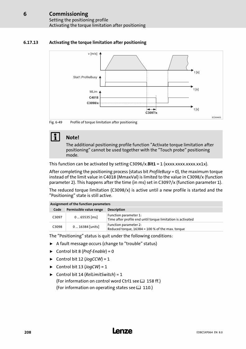
CommissioningSetting the positioning profileActivating the torque limitation after positioning
6
� 208 EDBCSXP064 EN 8.0
6.17.13 Activating the torque limitation after positioning
v [m/s]
t [s]
t [s]
t [s]
Stat1.ProfileBusy
MLim
C4018
C3098/x
C3097/x
ECSXA431
Fig. 6−49 Profile of torque limitation after positioning
� Note!
The additional positioning profile function "Activate torque limitation afterpositioning" cannot be used together with the "Touch probe" positioningmode.
This function can be activated by setting C3096/x.Bit1 = 1 (xxxx.xxxx.xxxx.xx1x).
After completing the positioning process (status bit ProfileBusy = 0), the maximum torqueinstead of the limit value in C4018 (MmaxVal) is limited to the value in C3098/x (functionparameter 2). This happens after the time (in ms) set in C3097/x (function parameter 1).
The reduced torque limitation (C3098/x) is active until a new profile is started and the"Positioning" state is still active.
Assignment of the function parameters
Code Permissible value range Description
C3097 0 ... 65535 [ms]Function parameter 1:Time after profile end until torque limitation is activated
C3098 0 ... 16384 [units]Function parameter 2:Reduced torque, 16384 = 100 % of the max. torque
The "Positioning" status is quit under the following conditions:
ƒ A fault message occurs (change to "trouble" status)
ƒ Control bit 8 (Prof−Enable) = 0
ƒ Control bit 12 (JogCCW) = 1
ƒ Control bit 13 (JogCW) = 1
ƒ Control bit 14 (RelLimitSwitch) = 1
(For information on control word Ctrl1 see � 158 ff.)
(For information on operating states see � 110.)
CommissioningSetting the positioning profile
Activating the profile continuation function
6
� 209EDBCSXP064 EN 8.0
6.17.14 Activating the profile continuation function
This function can be activated by setting C3096/x.Bit2 = 1 (xxxx.xxxx.xxxx.x1xx).
Profile continuation function is not active (default):
After a running positioning process is interrupted, e.g. by a fault, this positioning processis considered to be completed with regard to a restart of the same positioning profile. Aftera restart, the complete distance would be travelled anew in case of relative positioning.
Profile continuation function is active (C3096/x.bit2 = 1):
After a restart of the same profile, this is first travelled to the end automatically. If theaborted profile is to be continued when the profile is restarted (change to "Positioning"status), the corresponding profile number in control bit Ctrl1.PNoSet_x must also beselected. Status word1 contains the number of the interrupted profile (Stat1.PNoAct_x).
If another profile number is selected in the control word (bit Ctrl1.PNoSet_x), this otherprofile is executed and the interrupted profile will not be completed.
Entering the profile number 0 (Ctrl1.PNoSet_x =0) deletes the information on the stoppedprofile. A new positioning process can be started by entering a valid profile number(Ctrl1.PNoSet_x > 0).
If a positioning profile with activated profile continuation function is stopped, theStat2.ProfCont bit of status word2 is set to 1.
ƒ For information on the control word "Ctrl1" see � 158 et seqq.
ƒ For information on the status words "Stat1" and "Stat2" see � 161 et seqq.
� Note!
The profile continuation function for the profile set 15 is deactivatedindependent of the setting in C3096/x.bit2 if the profile set 15 is used as acontinuation profile of the Touch−Probe profile defined in profile set 14.

CommissioningSetting the positioning profileActivate immediate profile change during positioning (Direct Change)
6
� 210 EDBCSXP064 EN 8.0
6.17.15 Activate immediate profile change during positioning (Direct Change)
By setting C3096/x.Bit4 = 1 (xxxx.xxxx.xxx1.xxxx), the direct change function is activatedindividually for each positioning profile.
If a new profile number is defined during a positioning process, the new positioning profileis started immediately without completing the previous positioning process.
The profile parameters get active immediately and the positioning mode is executedaccordingly. The required speed changes due to various profile parameters are executedwith the new parameters without stopping in the meantime.

CommissioningConfiguring the electrical shaft ("E−Shaft")
6
� 211EDBCSXP064 EN 8.0
6.18 Configuring the electrical shaft ("E−Shaft")
The "Electrical shaft" drive function is used with linear drives if several drives are to betraversed with angular and speed synchronism, e.g. because they affect the same web.
The coupling is executed via a digital frequency signal which contains information on thesetpoint angle (setpoint position) and the setpoint speed.
Adjustable stretch factors serve to vary the material strength between the points of actionof the drives at the web. When the stretch factor = 1/1 (at the same mechanical ratio), bothdrives move exactly in angular and speed synchronism. If the stretch factor is set higherthan 1, the slave drive moves faster than the master drive and distortion is built up.
Ways to implement the electrical shaft function:
ƒ Coupling via digital frequency input X8
ƒ Coupling via MotionBus (CAN) X4
ƒ Coupling via EtherCAT at AIF interface X1 (EMF2192IB EtherCAT communicationmodule required)
The digital frequency for angle and speed of the "electrical shaft" is determined by theso−called digital frequency master. This master can be:
ƒ A master control with digital frequency output, CAN or EtherCAT interface.
ƒ A TTL encoder located at the web path or elsewhere at the machine.
ƒ A drive controller with digital frequency output, CAN or EtherCAT interface.

CommissioningConfiguring the electrical shaft ("E−Shaft")Setting the stretch factor (C3097 / C3098)
6
� 212 EDBCSXP064 EN 8.0
6.18.1 Setting the stretch factor (C3097 / C3098)
With the electrical shaft function, the setpoint speed can be adapted in the slave drive viathe stretch factor under C3097/C3098.
The required stretch factor results from the following factors:
ƒ Mechanical ratio of the master drive in proportion to the mechanical ratio of theslave drive (virtual gearbox).
ƒ Required speed overshoot of the slave drive to increase the web tension.
The stretch factor is specified as numerator (C3097) / denominator (C3098). Permissiblevalue range:
ƒ C3097: −32767 ... +32767 (negative values cause a reversal of direction of rotation).
ƒ C3098: 1 ... 32760
The master value input (at X8, X4 or X1) is multiplied by the numerator (C3097) and dividedby the denominator (C3098):
Drehzahlsollwert� �� Leitwert � C3097C3098
� Note!
ƒ The machine parameters for the gearbox ratio (C1202/C1203, � 103) onlyhave an effect on positioning and have no impact on the "electrical shaft"drive function.
ƒ The stretch factor (C3097/C3098) can be changed during operation of the"electrical shaft".

CommissioningConfiguring the electrical shaft ("E−Shaft")Setting the stretch factor (C3097 / C3098)
6
� 213EDBCSXP064 EN 8.0
Formulas for setting the stretch factor
Requirements:
ƒ The circumferential speeds of both rolls are to be the same.
ƒ Both rolls have the same diameter so that they must have the same speed too.
roll 1 roll 2
ratio i1 ratio i2
motor 1(Master)
motor 2(Slave)
stretchfactor
ECSXP004
Fig. 6−50 Electrical shaft: Master and slave roller drives affect the same web.
roll 1 Roll 1roll 2 Roll 2ratio i1 Mechanical gearbox ratio − masterratio i2 Mechanical gearbox ratio − slavestretch factor Stretch factor
Requirement: Synchronism of the rolls
nroll� 1 � nroll� 2
nmotor� 1
i1�
nmotor� 2
i2
stretchfactor �nmotor� 2nmotor� 1
� i2i1
stretch�factor � i2i1
� C3097C3098
Different roll diameters (d1, d2) must be considered for the stretch factor as follows:
stretch�factor � i2i1
� d1d2
� C3097C3098

CommissioningConfiguring the electrical shaft ("E−Shaft")Setting the stretch factor (C3097 / C3098)
6
� 214 EDBCSXP064 EN 8.0
Arithmetic example: The following is given ...
ƒ Roll diameter − master (d1) = 175 mm
ƒ Gearbox ration − master (i1) = 7,21
ƒ Roll diameter − slave (d2) = 225 mm
ƒ Gearbox ration − slave (i2) = 9,73
stretch�factor � 9, 737, 21
* 175225
stretch�factor � 9, 73 * 1757, 21 * 225
� 1702, 751622, 25
� 1, 049622
The stretch factor can only be entered as a rounded value:
ƒ C3097 = 1703
ƒ C3098 = 1622
Entered stretch factor:
stretch�factor � 17031622
� 1, 049938
This example results in a deviation of 0.03 % by rounding.
� Tip!
By extending the numerator and denominator by the factor 4, input values canbe found which correspond to the real stretch factor: C3097 = 6811; C3098 =6489
Entered stretch factor: 6811 / 6489 = 1.049622
This example with the extended input values does not show any deviations byrounding.
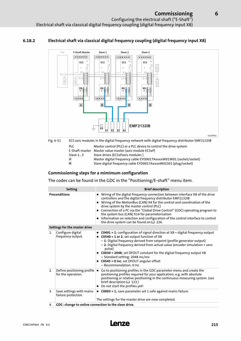
CommissioningConfiguring the electrical shaft ("E−Shaft")
Electrical shaft via classical digital frequency coupling (digital frequency input X8)
6
� 215EDBCSXP064 EN 8.0
6.18.2 Electrical shaft via classical digital frequency coupling (digital frequency input X8)
X8 X8 X8X8
� � � �
E-Shaft Master Slave 3Slave 2Slave 1
XS
PLC
X4X4 X4X4
12
0ECS ECS ECS ECS
X1X5
X2 X3 X4
EMF2132IB
12
01
20
X14X14 X14X14
12
01
20
12
0
ECSXP001
Fig. 6−51 ECS axis modules in the digital frequency network with digital frequency distributor EMF2132IB
PLC Master control (PLC) or a PLC device to control the drive systemE−Shaft master Master value master (axis module ECSxP)Slave 1...3 Slave drives (ECSxPaxis modules ) Master digital frequency cable EYD0017AxxxxW01W01 (socket/socket)� Slave digital frequency cable EYD0017AxxxxW01S01 (plug/socket)
Commissioning steps for a mimimum configuration
The codes can be found in the GDC in the "Positioning/E−shaft" menu item.
Setting Brief description
Preconditions � Wiring of the digital frequency connection between interface X8 of the drivecontrollers and the digital frequency distributor EMF2132IB
� Wiring of the MotionBus (CAN) X4 for the control and coordination of thedrive system by the master control (PLC)
� Connection of a PC via the "Global Drive Control" (GDC) operating program tothe system bus (CAN) X14 for parameterisation
� Information on selection and configuration of the control interface to controlthe drive system can be found on � 226.
Settings for the master drive
1. Configure digitalfrequency output.
� C0491 = 1; configuration of signal direction at X8 = digital frequency output� C0540 = 1 or 2; set output function of X8
– 1: Digital frequency derived from setpoint (profile generator output)– 2: Digital frequency derived from actual value (encoder simulation + zero
pulse)� C0030 = 2048; set DFOUT constant for the digital frequency output X8
– Standard setting: 2048 inc/rev� C0545 = 0 inc; set DFOUT angular offset
– Recommendation: 0 Inc
2. Define positioning profilefor the operation.
� Go to positioning profiles in the GDC parameter menu and create thepositioning profiles required for your application; e.g. with absolutepositioning or relative positioning in the continuous measuring system. (seebrief description � 123.)
� Do not start the profiles yet!
3. Save settings with mainsfailure protection.
� C0003 = 1; save parameter set 1 safe against mains failure.
The settings for the master drive are now completed.
4. GDC: change to online connection to the slave drive.
CommissioningConfiguring the electrical shaft ("E−Shaft")Electrical shaft via classical digital frequency coupling (digital frequency input X8)
6
� 216 EDBCSXP064 EN 8.0
Brief descriptionSetting
Settings for the slave drive
5. Configure digitalfrequency input X8.
The recommended setting value has been checked metrologically by Lenze.� C0491 = 0; Configuration of signal direction at X8 = digital frequency input� C0421 = 5 V; set voltage supply encoder at X8.
– 5V for TTL level� C0420 = 2048; set encoder increments X8
– Same number of increments as for the digital frequency output of themaster (C0030) or the master encoder.
� C4060 = xxx inc; set speed−proportional angular offset for the electrical shaft.The settings depends on the set output function of X8 in the master C0540:– C0540 = 1 in the master: C4060 = 15500 inc– C0540 = 2 in the master: C4060 = 2200 inc
6. Set the positioningprofile for electrical shaftoperation and stretchfactor.
� C3095 = 30; et positioning profile mode to "E−shaft via digitalfrequency (X8)".
� C3097 = 1000 / C3098 = 1000 ; set stretch factor numerator and denominatorfor the electrical shaft (e.g.: 1000 / 1000)
Notes:� Negative values in the numerator C3097 cause a reversal of direction of
rotation.� The machine parameters C1202 and C1203 for the gearbox ration are only
effective for positioning and do not influence the drive function "electricalshaft".
7. Save settings with mainsfailure protection.
� C0003 = 1; save parameter set 1 safe against mains failure.
The settings for the slave drive are now completed.
Make the same settings for each slave drive in the drive system (from 5th).
In order to put the drive system into operation, the following actions must be carried out:
ƒ Enable the slave drives by the master control (PLC) ( 241)and start the positioningprofile with the setting profile mode = electrical shaft ("E−shaft") ( 226).
ƒ Enable the master drive by the master control (PLC) and start the correspondingpositioning profiles ( 226).
� Tip!
For test purposes, the control interface can be set to "control via codes" withC4010 = 3. Then the control bits of the "Ctrl1" control word can be defined inGDC via C4040 to control the drives without a master control.
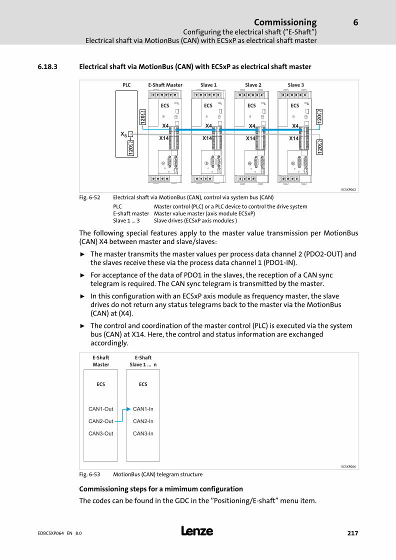
CommissioningConfiguring the electrical shaft ("E−Shaft")
Electrical shaft via MotionBus (CAN) with ECSxP as electrical shaft master
6
� 217EDBCSXP064 EN 8.0
6.18.3 Electrical shaft via MotionBus (CAN) with ECSxP as electrical shaft master
XS
X4
X14
X4
X14
X4
X14
X4
X14
12
0
12
0
12
01
20
12
01
20
E-Shaft Master Slave 3Slave 2Slave 1PLC
ECS ECS ECS ECS
ECSXP002
Fig. 6−52 Electrical shaft via MotionBus (CAN), control via system bus (CAN)
PLC Master control (PLC) or a PLC device to control the drive systemE−shaft master Master value master (axis module ECSxP)Slave 1 ... 3 Slave drives (ECSxP axis modules )
The following special features apply to the master value transmission per MotionBus(CAN) X4 between master and slave/slaves:
ƒ The master transmits the master values per process data channel 2 (PDO2−OUT) andthe slaves receive these via the process data channel 1 (PDO1−IN).
ƒ For acceptance of the data of PDO1 in the slaves, the reception of a CAN synctelegram is required. The CAN sync telegram is transmitted by the master.
ƒ In this configuration with an ECSxP axis module as frequency master, the slavedrives do not return any status telegrams back to the master via the MotionBus(CAN) at (X4).
ƒ The control and coordination of the master control (PLC) is executed via the systembus (CAN) at X14. Here, the control and status information are exchangedaccordingly.
E-Shaft
Master
E-Shaft
Slave 1 ... n
ECS ECS
CAN1-Out
CAN2-Out
CAN3-Out
CAN1-In
CAN2-In
CAN3-In
ECSXP006
Fig. 6−53 MotionBus (CAN) telegram structure
Commissioning steps for a mimimum configuration
The codes can be found in the GDC in the "Positioning/E−shaft" menu item.
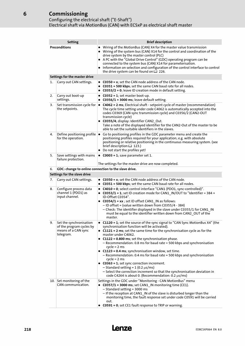
CommissioningConfiguring the electrical shaft ("E−Shaft")Electrical shaft via MotionBus (CAN) with ECSxP as electrical shaft master
6
� 218 EDBCSXP064 EN 8.0
Setting Brief description
Preconditions � Wiring of the MotionBus (CAN) X4 for the master value transmission� Wiring of the system bus (CAN) X14 for the control and coordination of the
drive system by the master control (PLC)� A PC with the "Global Drive Control" (GDC) operating program can be
connected to the system bus (CAN) X14 for parameterisation.� Information on selection and configuration of the control interface to control
the drive system can be found on � 226.
Settings for the master drive
1. Carry out CAN settings. � C0350 = x; set the CAN node address of the CAN node.� C0351 = 500 kbps; set the same CAN baud rate for all nodes.� C0353/2 = 0; leave ID creation mode in default setting.
2. Carry out boot−upsettings.
� C0352 = 1; set master boot−up.� C0356/1 = 3000 ms; leave default setting.
3. Set transmission cycle forthe setpoints.
� C4062 = 2 ms; Electrical shaft − setpoint cycle of master (recommendation)The cycle time setting under code C4062 is automatically accepted into thecodes C0369 (CAN−sync transmission cycle) and C0356/2 (CAN2−OUTtransmission cycle)
� C0355/4; display: Identifier CAN2_Out.Take a note of the displayed identifier for the CAN2−Out of the master to beable to set the suitable identifiers in the slaves.
4. Define positioning profilefor the operation.
� Go to positioning profiles in the GDC parameter menu and create thepositioning profiles required for your application; e.g. with absolutepositioning or relative positioning in the continuous measuring system. (seebrief description � 123.)
� Do not start the profiles yet!
5. Save settings with mainsfailure protection.
� C0003 = 1; save parameter set 1.
The settings for the master drive are now completed.
6. GDC: change to online connection to the slave drive.
Settings for the slave drive
7. Carry out CAN settings. � C0350 = x; set the CAN node address of the CAN node.� C0351 = 500 kbps; set the same CAN baud rate for all nodes.
8. Configure process datachannel 1 (PDO1) asinput channel.
� C4010 = 0; select control interface "CAN1 (PDO1, sync−controlled)".� C0353/1 = 1; set ID creation mode for CAN1_IN/OUT to "Identifier = 384 +
ID−Offset C0354".� C0354/1 = xx ; set ID offset CAN1_IN as follows:
– ID offset = (value written down from C0355/4 − 384)– Check: The identifier displayed in the slave under C0355/1 for CAN1_IN
must be equal to the identifier written down from CAN2_OUT of themaster.
9. Set the synchronisationof the program cycles bymeans of a CAN synctelegram.
� C1120 = 1; set the source of the sync signal to "CAN Sync MotionBus X4" (thesynchronisation function will be activated).
� C1121 = 2 ms; set the same time for the synchronisation cycle as for themaster under C4062.
� C1122 = 0.800 ms; set the synchronisation phase.– Recommendation: 0.8 ms for baud rate = 500 kbps and synchronisation
cycle = 2 ms� C1123 = 0.4 ms; synchronisation window, set time.
– Recommendation: 0.4 ms for baud rate = 500 kbps and synchronisationcycle = 2 ms
� C0363 = 1; set sync correction increment.– Standard setting = 1 (0.2 �s/ms)– Select the correction increment so that the synchronisation deviation in
code C4264 is about 0. (Recommendation: 0.2 �s/ms)
10. Set monitoring of theCAN communication.
Settings in the GDC under "Monitoring − CAN MotionBus" menu� C0357/1 = 3000 ms; set CAN1_IN monitoring time (CE1).
– Standard setting = 3000 ms– If the reception at CAN1_IN of the slave is disturbed longer than the
monitoring time, the fault response set under code C0591 will be carriedout.
� C0591 = 0; set CE1 fault response to TRIP or warning.
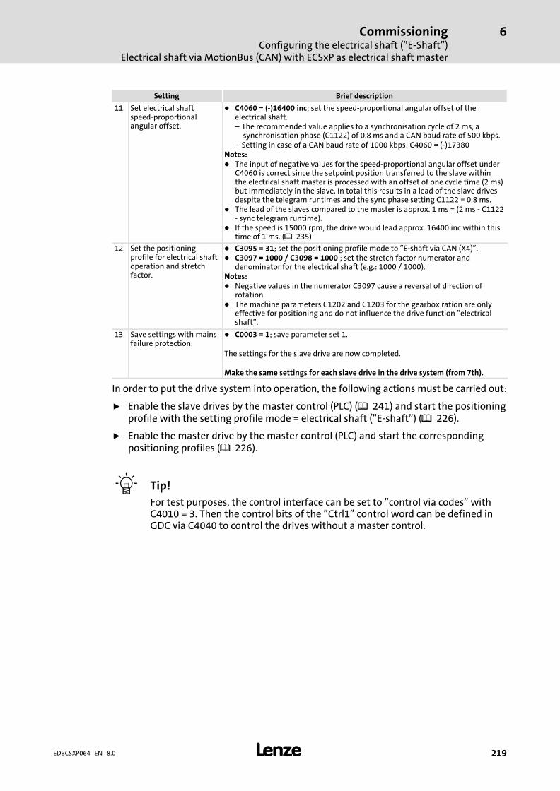
CommissioningConfiguring the electrical shaft ("E−Shaft")
Electrical shaft via MotionBus (CAN) with ECSxP as electrical shaft master
6
� 219EDBCSXP064 EN 8.0
Brief descriptionSetting
11. Set electrical shaftspeed−proportionalangular offset.
� C4060 = (−)16400 inc; set the speed−proportional angular offset of theelectrical shaft.– The recommended value applies to a synchronisation cycle of 2 ms, a
synchronisation phase (C1122) of 0.8 ms and a CAN baud rate of 500 kbps.– Setting in case of a CAN baud rate of 1000 kbps: C4060 = (−)17380
Notes:� The input of negative values for the speed−proportional angular offset under
C4060 is correct since the setpoint position transferred to the slave withinthe electrical shaft master is processed with an offset of one cycle time (2 ms)but immediately in the slave. In total this results in a lead of the slave drivesdespite the telegram runtimes and the sync phase setting C1122 = 0.8 ms.
� The lead of the slaves compared to the master is approx. 1 ms = (2 ms − C1122− sync telegram runtime).
� If the speed is 15000 rpm, the drive would lead approx. 16400 inc within thistime of 1 ms. (� 235)
12. Set the positioningprofile for electrical shaftoperation and stretchfactor.
� C3095 = 31; set the positioning profile mode to "E−shaft via CAN (X4)".� C3097 = 1000 / C3098 = 1000 ; set the stretch factor numerator and
denominator for the electrical shaft (e.g.: 1000 / 1000).Notes:� Negative values in the numerator C3097 cause a reversal of direction of
rotation.� The machine parameters C1202 and C1203 for the gearbox ration are only
effective for positioning and do not influence the drive function "electricalshaft".
13. Save settings with mainsfailure protection.
� C0003 = 1; save parameter set 1.
The settings for the slave drive are now completed.
Make the same settings for each slave drive in the drive system (from 7th).
In order to put the drive system into operation, the following actions must be carried out:
ƒ Enable the slave drives by the master control (PLC) ( 241) and start the positioningprofile with the setting profile mode = electrical shaft ("E−shaft") ( 226).
ƒ Enable the master drive by the master control (PLC) and start the correspondingpositioning profiles ( 226).
� Tip!
For test purposes, the control interface can be set to "control via codes" withC4010 = 3. Then the control bits of the "Ctrl1" control word can be defined inGDC via C4040 to control the drives without a master control.

CommissioningConfiguring the electrical shaft ("E−Shaft")Electrical shaft via MotionBus (CAN) with PLC as electrical shaft master
6
� 220 EDBCSXP064 EN 8.0
6.18.4 Electrical shaft via MotionBus (CAN) with PLC as electrical shaft master
In this operating mode, control information and master value are comprised in a telegramand individually transmitted to each slave.
The function of the master as a master value source can be taken over by a higher−levelcontrol (PLC). The speed and position−controlled slave drives follow the cyclic master value(angle) determined by the master as path followers.
In this configuration of the electrical shaft, the master control (PLC) takes over the functionof the E−shaft master and the control of the slave drives (start / stop of the positioningprofiles).
Slave 3Slave 2Slave 1PLC
ECS ECS ECS
XS
X4 X4
12
0
12
01
20
X14X14 X14
ECSXP003
Fig. 6−54 Electrical shaft via MotionBus (CAN) with higher−level control as electrical shaft master
PLC Higher−level control (PLC) as electrical shaft master and for control of the drivesystem
Slave 1 ... 3 Slave drives (ECSxP axis modules )
Only the MotionBus (CAN) at X4 is used for data exchange between the master control(PLC) and the slave drives.
Each slave drive receives an individual process data telegram from the master within afixed cycle time. This contains the "Ctrl1" control word with the control bits from themaster to the slaves and the master value for the electrical shaft function.
The slaves send a status telegram each back to the master. For estimating the bus load, twotelegrams must be set per slave. Moreover, one CAN sync telegram is transmitted cyclicallyby the master. More telegrams are transmitted for the parameter communication.
The total number of the CAN telegrams to be transmitted via the MotionBus (CAN) and theset CAN baud rate determine how many slave drives can be connected when a setpointcycle is defined. Or vice versa, which minimum setpoint cycle can be set with a definednumber of slave drives.
The following table can serve as indication for the maximum number of the slaves and thesetpoint cycle:
Baud rate 500 kbps 1000 kbps
Setpoint cycle 2 ms 4 ms 6 ms 2 ms 4 ms 6 ms
Number of slaves 2 5 8 4 10 16
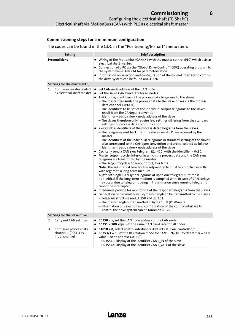
CommissioningConfiguring the electrical shaft ("E−Shaft")
Electrical shaft via MotionBus (CAN) with PLC as electrical shaft master
6
� 221EDBCSXP064 EN 8.0
Commissioning steps for a mimimum configuration
The codes can be found in the GDC in the "Positioning/E−shaft" menu item.
Setting Brief description
Preconditions � Wiring of the MotionBus (CAN) X4 with the master control (PLC) which acts aselectrical shaft master.
� Connection of a PC via the "Global Drive Control" (GDC) operating program tothe system bus (CAN) X14 for parameterisation.
� Information on selection and configuration of the control interface to controlthe drive system can be found on � 226.
Settings for the master (PLC)
1. Configure master controlas electrical shaft master.
� Set CAN node address of the CAN node.� Set the same CAN baud rate for all nodes.� Tx−COB−IDs; identifiers of the process data telegrams to the slaves
– The master transmits the process data to the slave drives via the processdata channel 1 (PDO1).
– The identifiers to be set of the individual output telegrams to the slavesresult from the CANopen convention: Identifier = basic value + node address of the slave
– The slaves therefore only require few settings differing from the standardsettings for process data communication.
� Rx−COB IDs, identifiers of the process data telegrams from the slaves– The telegrams sent back from the slaves via PDO1 are received by the
master.– The identifiers of the individual telegrams in standard setting of the slaves
also correspond to the CANopen convention and are calculated as follows:Identifier = basic value + node address of the slave
� Cyclically send a CAN sync telegram (� 420) with the identifier = 0x80.� Master setpoint cycle; Interval in which the process data and the CAN sync
telegram are transmitted by the master– The setpoint cycle is to amount to 2, 4 or 6 ms.Note: The set interval time for the setpoint cycle must be complied exactlywith regard to a long−term medium.A jitter of single CAN sync telegrams of up to one telegram runtime isnon−critical if the long−term medium is complied with. In case of CAN, delaysmay occur due to telegrams being in transmission since running telegramscannot be interrupted.
� If required, provide for monitoring of the response telegrams from the slaves.� Generation of the master value/master angle to be transmitted to the slaves
– Telegram structure see � 158 and � 161.– The master angle is transmitted in bytes 5 ... 8 (PosDirect).– Information on selection and configuration of the control interface to
control the drive system can be found on � 226.
Settings for the slave drive
2. Carry out CAN settings. � C0350 = x; set the CAN node address of the CAN node.� C0351 = 500 kbps; set the same CAN baud rate for all nodes.
3. Configure process datachannel 1 (PDO1) asinput channel.
� C4010 = 0; select control interface "CAN1 (PDO1, sync−controlled)".� C0353/1 = 0; set the ID creation mode for CAN1_IN/OUT to "Identifier = base
value + node address C0350".– C0355/1: Display of the identifier CAN1_IN of the slave– C0355/2: Display of the identifier CAN1_OUT of the slave

CommissioningConfiguring the electrical shaft ("E−Shaft")Electrical shaft via MotionBus (CAN) with PLC as electrical shaft master
6
� 222 EDBCSXP064 EN 8.0
Brief descriptionSetting
4. Set the synchronisationof the program cycles bymeans of a CAN synctelegram.
� C1120 = 1; set the source of the sync signal to "CAN Sync MotionBus X4" (thesynchronisation function will be activated).
� C1121 = 2 ms; set the same time for the synchronisation cycle as for themaster.
� C1122 = 0.800 ms; set the synchronisation phase.– Recommendation: 0.8 ms for baud rate = 500 kbps and synchronisation
cycle = 2 ms� C1123 = 0,4 ms; synchronisation window, set time� Recommendation: 0.4 ms for baud rate = 500 kbps and synchronisation
cycle = 2 ms� C0363 = 1; set sync correction increment.
– Standard setting = 1 (0.2 �s/ms)– Select the correction increment so that the synchronisation deviation in
code C4264 is about 0. (Recommendation: 0.2 �s/ms)� C0366 = 1; activate transmission of CAN1_OUT sync response message
(response).
5. Set monitoring of theCAN communication.
Settings in the GDC under "Monitoring − CAN MotionBus" menu� C0357/1 = 3000 ms; set CAN1_IN monitoring time (CE1).
– Standard setting = 3000 ms– If the reception at CAN1_IN of the slave is disturbed longer than the
monitoring time, the fault response set under code C0591 will be carriedout.
� C0591 = 0; set CE1 fault response to TRIP or warning.
6. Set electrical shaftspeed−proportionalangular offset.
� C4060 = (−)16400 inc; set the speed−proportional angular offset for theelectrical shaft.– The recommended value applies for a synchronisation cycle (C1121) of
2 ms, a synchronisation phase (C1122) of 0.8 ms and a CAN baud rate(C0351) of 500 kbps.
– Setting in case of a CAN baud rate of 1000 kbit/s: C4060 = (−)17380.Notes:� The input of negative values for the speed−proportional angular offset under
C4060 is correct since the setpoint position transferred to the slave withinthe electrical shaft master is processed with an offset of one cycle time (2 ms)but immediately in the slave. In total this results in a lead of the slave drivesdespite the telegram runtimes and the sync phase setting C1122 = 0.8 ms.
� The lead of the slaves compared to the master is approx. 1 ms = (2 ms − C1122− sync telegram runtime).
� If the speed is 15000 rpm, the drive would lead approx. 16400 inc within thistime of 1 ms. (� 235)
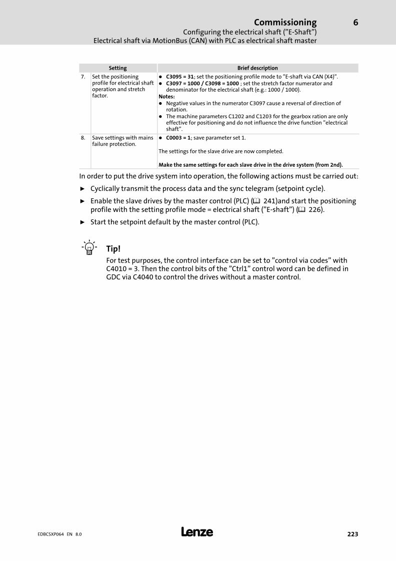
CommissioningConfiguring the electrical shaft ("E−Shaft")
Electrical shaft via MotionBus (CAN) with PLC as electrical shaft master
6
� 223EDBCSXP064 EN 8.0
Brief descriptionSetting
7. Set the positioningprofile for electrical shaftoperation and stretchfactor.
� C3095 = 31; set the positioning profile mode to "E−shaft via CAN (X4)".� C3097 = 1000 / C3098 = 1000 ; set the stretch factor numerator and
denominator for the electrical shaft (e.g.: 1000 / 1000).Notes:� Negative values in the numerator C3097 cause a reversal of direction of
rotation.� The machine parameters C1202 and C1203 for the gearbox ration are only
effective for positioning and do not influence the drive function "electricalshaft".
8. Save settings with mainsfailure protection.
� C0003 = 1; save parameter set 1.
The settings for the slave drive are now completed.
Make the same settings for each slave drive in the drive system (from 2nd).
In order to put the drive system into operation, the following actions must be carried out:
ƒ Cyclically transmit the process data and the sync telegram (setpoint cycle).
ƒ Enable the slave drives by the master control (PLC) ( 241)and start the positioningprofile with the setting profile mode = electrical shaft ("E−shaft") ( 226).
ƒ Start the setpoint default by the master control (PLC).
� Tip!
For test purposes, the control interface can be set to "control via codes" withC4010 = 3. Then the control bits of the "Ctrl1" control word can be defined inGDC via C4040 to control the drives without a master control.
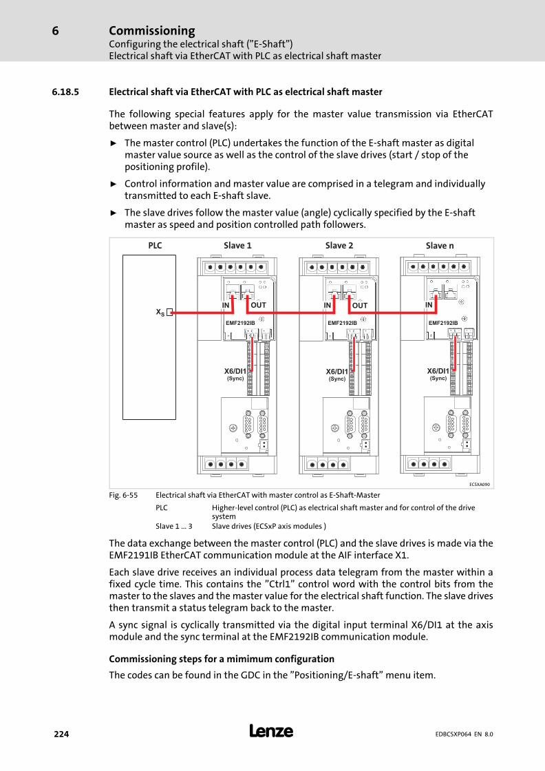
CommissioningConfiguring the electrical shaft ("E−Shaft")Electrical shaft via EtherCAT with PLC as electrical shaft master
6
� 224 EDBCSXP064 EN 8.0
6.18.5 Electrical shaft via EtherCAT with PLC as electrical shaft master
The following special features apply for the master value transmission via EtherCATbetween master and slave(s):
ƒ The master control (PLC) undertakes the function of the E−shaft master as digitalmaster value source as well as the control of the slave drives (start / stop of thepositioning profile).
ƒ Control information and master value are comprised in a telegram and individuallytransmitted to each E−shaft slave.
ƒ The slave drives follow the master value (angle) cyclically specified by the E−shaftmaster as speed and position controlled path followers.
Slave nSlave 2Slave 1PLC
XS
OUTOUT IN ININ
EMF2192IB EMF2192IB EMF2192IB
X6/DI1(Sync)
X6/DI1(Sync)
X6/DI1(Sync)
ECSXA090
Fig. 6−55 Electrical shaft via EtherCAT with master control as E−Shaft−Master
PLC Higher−level control (PLC) as electrical shaft master and for control of the drivesystem
Slave 1 ... 3 Slave drives (ECSxP axis modules )
The data exchange between the master control (PLC) and the slave drives is made via theEMF2191IB EtherCAT communication module at the AIF interface X1.
Each slave drive receives an individual process data telegram from the master within afixed cycle time. This contains the "Ctrl1" control word with the control bits from themaster to the slaves and the master value for the electrical shaft function. The slave drivesthen transmit a status telegram back to the master.
A sync signal is cyclically transmitted via the digital input terminal X6/DI1 at the axismodule and the sync terminal at the EMF2192IB communication module.
Commissioning steps for a mimimum configuration
The codes can be found in the GDC in the "Positioning/E−shaft" menu item.
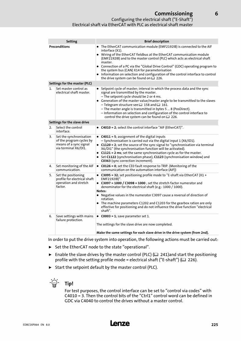
CommissioningConfiguring the electrical shaft ("E−Shaft")
Electrical shaft via EtherCAT with PLC as electrical shaft master
6
� 225EDBCSXP064 EN 8.0
Setting Brief description
Preconditions � The EtherCAT communication module (EMF2192IB) is connected to the AIFinterface (X1).
� Wiring of the EtherCAT fieldbus at the EtherCAT communication module(EMF2192IB) and to the master control (PLC) which acts as electrical shaftmaster.
� Connection of a PC via the "Global Drive Control" (GDC) operating program tothe system bus (CAN) X14 for parameterisation
� Information on selection and configuration of the control interface to controlthe drive system can be found on � 226.
Settings for the master (PLC)
1. Set master control aselectrical shaft master.
� Setpoint cycle of master; interval in which the process data and the syncsignal are transmitted by the master.– The setpoint cycle should be 2 or 4 ms.
� Generation of the master value/master angle to be transmitted to the slaves– Telegram structure see � 158 and � 161.– The master angle is transmitted in bytes 5 ... 8 (PosDirect).– Information on selection and configuration of the control interface to
control the drive system can be found on � 226.
Settings for the slave drive
2. Select the controlinterface.
� C4010 = 2; select the control interface "AIF (EtherCAT)".
3. Set the synchronisationof the program cycles bymeans of a sync signalvia terminal X6/DI1.
� C4011 = 5; assignment of the digital inputs– Synchronisation is carried out via the digital input 1 (X6/ID1).
� C1120 = 2; set the source of the sync signal to "synchronisation via terminalX6/DI1" (the synchronisation function will be activated).
� C1121 = 2 ms; set the same synchronisation cycle as for the master.� Set C1122 (synchronisation phase), C1123 (synchronisation window) and
C0363 (sync correction increment).
4. Set monitoring of the AIFcommunication.
� C0126 = 0; set the CE0 fault response to TRIP. (Monitoring of thecommunication on the automation interface (AIF))
5. Set the positioningprofile for electrical shaftoperation and stretchfactor.
� C3095 = 32; set positioning profile mode to "E−shaft via EtherCAT (X1 +EMF2192IB)".
� C3097 = 1000 / C3098 = 1000 ; set the stretch factor numerator anddenominator for the electrical shaft (e.g.: 1000 / 1000).
Notes:� Negative values in the numerator C3097 cause a reversal of direction of
rotation.� The machine parameters C1202 and C1203 for the gearbox ration are only
effective for positioning and do not influence the drive function "electricalshaft".
6. Save settings with mainsfailure protection.
� C0003 = 1; save parameter set 1.
The settings for the slave drive are now completed.
Make the same settings for each slave drive in the drive system (from 2nd).
In order to put the drive system into operation, the following actions must be carried out:
ƒ Set the EtherCAT node to the state "operational".
ƒ Enable the slave drives by the master control (PLC) ( 241)and start the positioningprofile with the setting profile mode = electrical shaft ("E−shaft") ( 226).
ƒ Start the setpoint default by the master control (PLC).
� Tip!
For test purposes, the control interface can be set to "control via codes" withC4010 = 3. Then the control bits of the "Ctrl1" control word can be defined inGDC via C4040 to control the drives without a master control.

CommissioningStarting positioning profiles (ProfEnable, profile number)
6
� 226 EDBCSXP064 EN 8.0
6.19 Starting positioning profiles (ProfEnable, profile number)
There are two possibilities for starting positioning profiles via the higher−level control(PLC):
1. Start via the control bit Ctrl1.ProfEnable
– Activation time until execution: up to 30 ms
– From Posi&Shaft V2.0 onwards: activation time 18 ... 24 ms (up to 6 ms variationdepending on the moment of transmission)
2. Start by selection of a new profile number (PNoSet_x) while the control bitCtrl1.ProfEnable is set to 1.
– Activation time until execution: 12 ... 18 ms (up to 6 ms variation depending onthe moment of transmission); (fastest option)
� Note!
Ctrl1.ProfEnable must remain set to "1" until the target position has beenreached. The drive stops immediately if the control bit Ctrl1.ProfEnable is resetto "0" during a running positioning profile.
(See also chapter 6.11.1 "Control word Ctrl1" ( 159).)
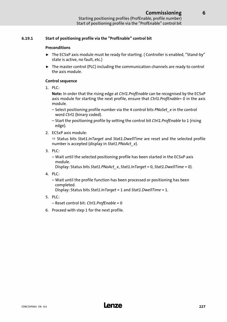
CommissioningStarting positioning profiles (ProfEnable, profile number)
Start of positioning profile via the "ProfEnable" control bit
6
� 227EDBCSXP064 EN 8.0
6.19.1 Start of positioning profile via the "ProfEnable" control bit
Preconditions
ƒ The ECSxP axis module must be ready for starting. ( Controller is enabled, "Stand−by"state is active, no fault, etc.)
ƒ The master control (PLC) including the communication channels are ready to controlthe axis module.
Control sequence
1. PLC:
Note: In order that the rising edge at Ctrl1.ProfEnable can be recognised by the ECSxPaxis module for starting the next profile, ensure that Ctrl1.ProfEnable= 0 in the axismodule.
– Select positioning profile number via the 4 control bits PNoSet_x in the controlword Ctrl1 (binary coded).
– Start the positioning profile by setting the control bit Ctrl1.ProfEnable to 1 (risingedge).
2. ECSxP axis module:
Status bits Stat1.InTarget and Stat1.DwellTime are reset and the selected profilenumber is accepted (display in Stat1.PNoAct_x).
3. PLC:
– Wait until the selected positioning profile has been started in the ECSxP axismodule. Display: Status bits Stat1.PNoAct_x, Stat1.InTarget = 0, Stat1.DwellTime = 0).
4. PLC:
– Wait until the profile function has been processed or positioning has beencompleted.Display: Status bits Stat1.InTarget = 1 and Stat1.DwellTime = 1.
5. PLC:
– Reset control bit: Ctrl1.ProfEnable = 0
6. Proceed with step 1 for the next profile.
CommissioningStarting positioning profiles (ProfEnable, profile number)Start of positioning profile by selecting a new profile number "PNoSet_x"
6
� 228 EDBCSXP064 EN 8.0
6.19.2 Start of positioning profile by selecting a new profile number "PNoSet_x"
Precondition
The ECSxP axis module must be in the "positioning" mode and thus ready to start. The axismodule is in the "positioning" mode when a positioning process has been completed, thecontroller is still enabled and the control bit ProfileEnable remains set.
Control sequence
1. PLC:
– Select and thus start the positioning profile via the 4 control bits PNoSet_x (binarycoded) in the control word Ctrl1.
– The control bit Ctrl1.ProfEnable remains set.
2. ECSxP axis module:
Status bits Stat1.InTarget and Stat1.DwellTime are reset and the selected profilenumber is accepted (display in Stat1.PNoAct_x).
3. PLC:
– Wait until the selected positioning profile has been started in the ECSxPaxismodule.Display: Status bits Stat1.PNoAct_x, Stat1.InTarget = 0, Stat1.DwellTime = 0).
4. PLC:
– Wait until the profile function has been processed or positioning has beencompleted.Display: Status bits Stat1.InTarget = 1 and Stat1.DwellTime = 1.
If the target position has been reached, status bits Stat1.InTarget andStat1.DwellTime are both set to 1.
5. Proceed with step 1 for the next profile.
� Tip!
Quickest possible profile sequence by specifying new profile numbers duringthe running positioning process in step 4 of the control sequence:
ƒ In this case, the sequence profile is started immediately after the profilegenerator has reached the previous target position (setpoint−based).
ƒ The dwell time is not awaited anymore and the Stat1.DwellTime status bit isnot set in the meantime.
ƒ Depending on the setting of the target window, it may occur thatStat1.InTarget status bit is not set either when changing to the new profile.
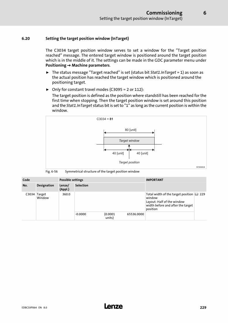
CommissioningSetting the target position window (InTarget)
6
� 229EDBCSXP064 EN 8.0
6.20 Setting the target position window (InTarget)
The C3034 target position window serves to set a window for the "Target positionreached" message. The entered target window is positioned around the target positionwhich is in the middle of it. The settings can be made in the GDC parameter menu underPositioning � Machine parameters.
ƒ The status message "Target reached" is set (status bit Stat1.InTarget = 1) as soon asthe actual position has reached the target window which is positioned around thepositioning target.
ƒ Only for constant travel modes (C3095 = 2 or 112):
The target position is defined as the position where standstill has been reached for thefirst time when stopping. Then the target position window is set around this positionand the Stat1.InTarget status bit is set to "1" as long as the current position is within thewindow.
Target position
C3034 = 81
80 [unit]
40 [unit] 40 [unit]
Target window
ECSXA414
Fig. 6−56 Symmetrical structure of the target position window
Code Possible settings IMPORTANT
No. Designation Lenze/{Appl.}
Selection
C3034 TargetWindow
360.0 Total width of the target positionwindowLayout: Half of the windowwidth before and after the targetposition
� 229
−0.0000 {0.0001units}
65536.0000

CommissioningSetting the target position window (InTarget)
6
� 230 EDBCSXP064 EN 8.0
� Tip!
The target window for the status bit Stat1.InTarget is evaluated independentof the position setpoint of the profile generator. This means, depending on thesetting of the target window and the drive properties, it may happen that thestatus bit Stat1.InTarget is already set before the position setpoint of theprofile generator has reached the target position.
If this is not required, it is possible to evaluate the following status bitsAND’ed:
ƒ Stat1.InTargetAND Stat1.DwellTime ( 161)
This has the effect that the setpoint from the profile generator must at leasthave reached the target position (with dwell time = 0) or even a dwell timemust be waited for (with dwell time > 0).

CommissioningDefining the window for standstill message
6
� 231EDBCSXP064 EN 8.0
6.21 Defining the window for standstill message
The standstill message is activated if the actual speed falls below a certain speed limitvalue (independent of the direction of rotation). The limit value (C3017) and hysteresis(C3018) can be set in the GDC parameter menu under Positioning � Machine parameters.
Function sequence
ƒ If the current speed falls below the speed threshold (C3017), status bit Stat2.Nmin isset to 1.
ƒ Only when the current speed exceeds the value of C3017 + C3018 again, status bitStat2.Nmin is reset to "0".
Code Possible settings IMPORTANT
No. Designation Lenze/{Appl.}
Selection
C3017 Lim.n=0−Flag 0.10 Limit value for speed, (nminsignal)
� 231
0.01 {0.01 %} 100.00 If the value falls below the limitvalue, the status bit Stat2.Nminis set to 1.
C3018 Hyst.n=0−Flag 0.10 Hysteresis for speed (nmin signal) � 231
0.00 {0.01 %} 100.00

CommissioningDefining the dwell time
6
� 232 EDBCSXP064 EN 8.0
6.22 Defining the dwell time
The dwell time entered under C3035 serves to give the drive time to remove a possiblyavailable following error when the target position has been reached.
The setting can be made in the GDC parameter menu in Positioning � Positioningbehaviour.
ƒ The dwell time starts to elapse when the position setpoint from the profilegenerator has reached the target position (status bits Stat1.ProfileBusy = 0 andStat2.AuxProfileBusy = 0).
ƒ After the dwell time has elapsed, status bit Stat1.DwellTime is set to 1.
ƒ If a new positioning is started, status bit Stat1.DwellTime is set to 0.
t [s]
v [m/s]
t [s]
g_bDwellTime
TRUE
FALSE
Dwell time�
�
ECSXA415
Fig. 6−57 Definition of the dwell time
� Actual value profile� Setpoint profile
Code Possible settings IMPORTANT
No. Designation Lenze/{Appl.}
Selection
C3035 DwellTime 50 Dwell time after end of profile � 232
0 {1 ms} 65535 Time required from positioningprofile end (setpoint generatorhas reached target position) tothe setting of status bitStat1.DwellTime = 1

CommissioningFollowing error monitoring (C3030, C3031)
6
� 233EDBCSXP064 EN 8.0
6.23 Following error monitoring (C3030, C3031)
The following error monitoring function is triggered if the drive cannot follow the definedposition setpoint within the tolerances to be set.
Mechanical stiffness may be the reason or the setpoint selection comprises an accelerationwhich is too high for the drive power.
v [m/s]
t [s]
� � �
A B
ECSXA416
Fig. 6−58 Following error
Setpoint speed profile (the area below the curve corresponds to the path)� Profile travelled� The drive decelerates, a difference between set position and actual position arises.� Following error tolerance is exceeded.� End of the set profile
For the following error monitoring mode it is checked whether the current following error(difference between set position and actual position) is higher than the set following errortolerance. Two following error tolerances can be set which trip different responses:
ƒ Following error warning (C3030):
If the current following error exceeds the tolerance set under C3030, a warning isoutput as fault response only, and the movement of the drive is not interrupted. Thewarning is to announce an upcoming stiffness so that the master control (PLC) caninitiate a controlled response.
The status bit Stat2.FollowErrWarn is set to "1" as long as the current following erroris higher than the tolerance C3030.
If a profile is being processed ("Positioning" status), the start for the next positioningprofile to be travelled (e.g. sequence profile with touch probe positioning) is notexecuted as long as the warning is active.

CommissioningFollowing error monitoring (C3030, C3031)
6
� 234 EDBCSXP064 EN 8.0
ƒ Following error−FAIL−QSP (C3031):
The following error limit C3031 must be set higher than the tolerance under C3030.
If the current following error exceeds the limit set in C3031, the FAIL−QSP fault responseis triggered. The drive brakes to standstill over the set quick stop deceleration time(C0105).
Fault response FAIL−QSP "FollowErr"
– The drive changes to the "Trouble" state.
– The quick stop deceleration time is set via C0105 in the GDC parameter menuunder Positioning�� Machine parameters.
– The following errors are monitored in all motion states of the drive. A reset of thefault message is required (e.g. control bit Ctrl1.TripReset = 1).
� Note!
In case of the ECSxP axis module, the fault responses "Warning" and"FAIL−QSP" cannot be changed or switched off for following error monitoring.
However, it is possible to set the following error tolerances to the maximumvalue which practically switches off the following error monitoring.
Code Possible settings IMPORTANT
No. Designation Lenze/{Appl.}
Selection
C3030 FollErrWarn 360.0 Following error tolerance(warning)
� 233
0.0000 {0.0001units}
214000.0000 If the tolerance is exceeded, the"FollowErr" warning will betriggered. The status bitStat2.FollowErrWarn is set to "1"(TRUE).Note: The acceptance of changedsettings requires a status changevia the "Stand−By" status!
C3031 FollowErrQSP 720.0 Following error tolerance(Fail−QSP)
� 233
0.0000 {0.0001units}
214000.0000 If the tolerance is exceeded, theFail−QSP "FollowErr" fault istriggered and the drive isstopped through the QSP ramp.Note: The acceptance of changedsettings requires a status changevia the "Stand−By" status!
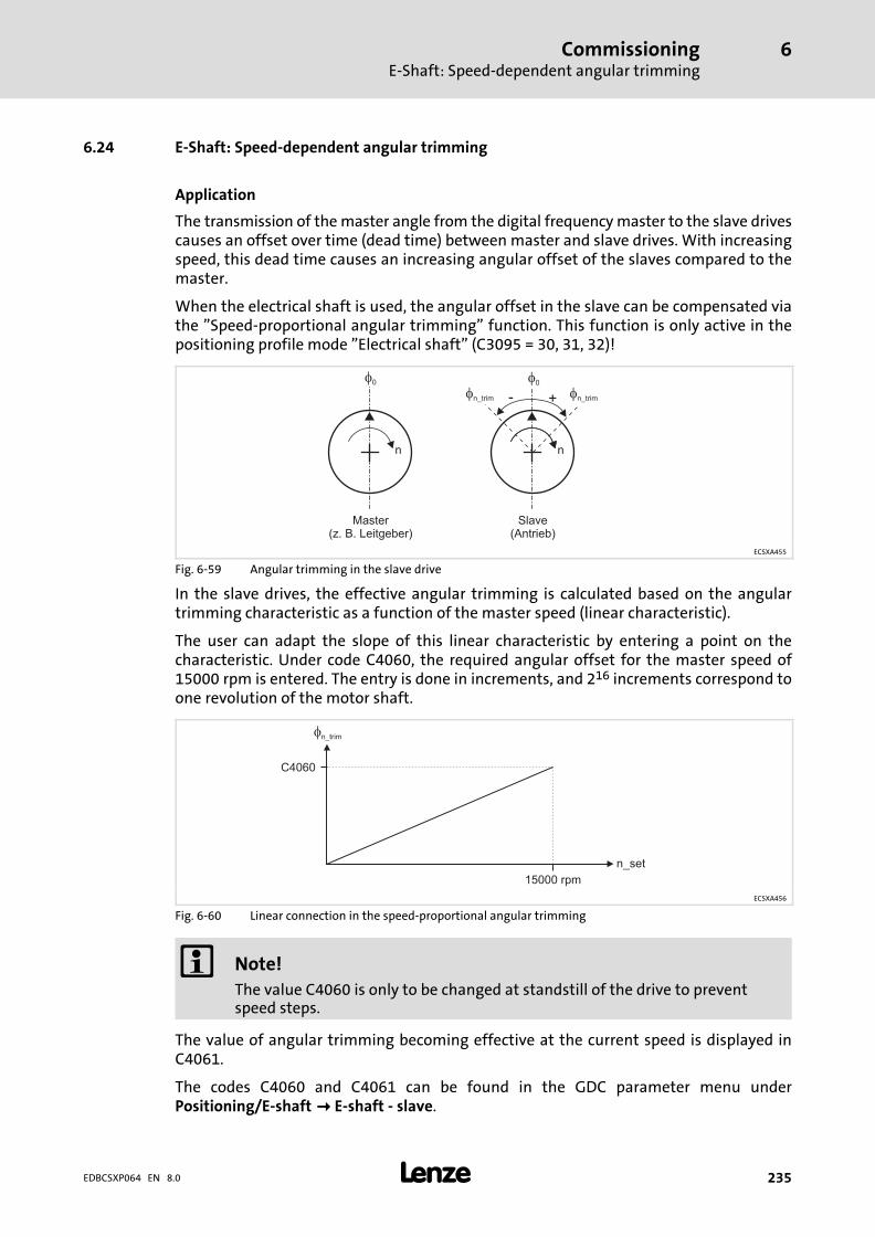
CommissioningE−Shaft: Speed−dependent angular trimming
6
� 235EDBCSXP064 EN 8.0
6.24 E−Shaft: Speed−dependent angular trimming
Application
The transmission of the master angle from the digital frequency master to the slave drivescauses an offset over time (dead time) between master and slave drives. With increasingspeed, this dead time causes an increasing angular offset of the slaves compared to themaster.
When the electrical shaft is used, the angular offset in the slave can be compensated viathe "Speed−proportional angular trimming" function. This function is only active in thepositioning profile mode "Electrical shaft" (C3095 = 30, 31, 32)!
�
n
�0
�
n
�0
- +�n_trim �n_trim
Master(z. B. Leitgeber)
Slave(Antrieb)
ECSXA455
Fig. 6−59 Angular trimming in the slave drive
In the slave drives, the effective angular trimming is calculated based on the angulartrimming characteristic as a function of the master speed (linear characteristic).
The user can adapt the slope of this linear characteristic by entering a point on thecharacteristic. Under code C4060, the required angular offset for the master speed of15000 rpm is entered. The entry is done in increments, and 216 increments correspond toone revolution of the motor shaft.
�n_trim
n_set
15000 rpm
C4060
ECSXA456
Fig. 6−60 Linear connection in the speed−proportional angular trimming
� Note!
The value C4060 is only to be changed at standstill of the drive to preventspeed steps.
The value of angular trimming becoming effective at the current speed is displayed inC4061.
The codes C4060 and C4061 can be found in the GDC parameter menu underPositioning/E−shaft�� E−shaft − slave.
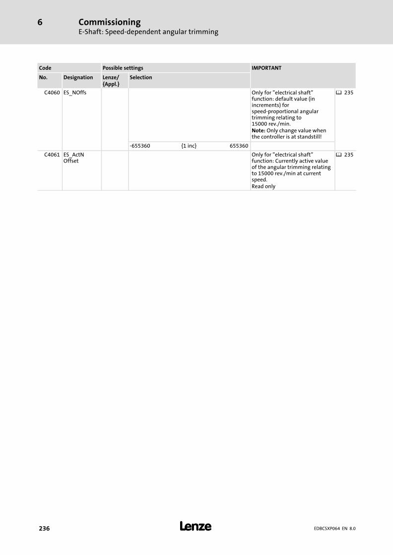
CommissioningE−Shaft: Speed−dependent angular trimming
6
� 236 EDBCSXP064 EN 8.0
Code Possible settings IMPORTANT
No. Designation Lenze/{Appl.}
Selection
C4060 ES_NOffs Only for "electrical shaft"function: default value (inincrements) forspeed−proportional angulartrimming relating to15000 rev./min.Note: Only change value whenthe controller is at standstill!
� 235
−655360 {1 inc} 655360
C4061 ES_ActNOffset
Only for "electrical shaft"function: Currently active valueof the angular trimming relatingto 15000 rev./min at currentspeed.Read only
� 235
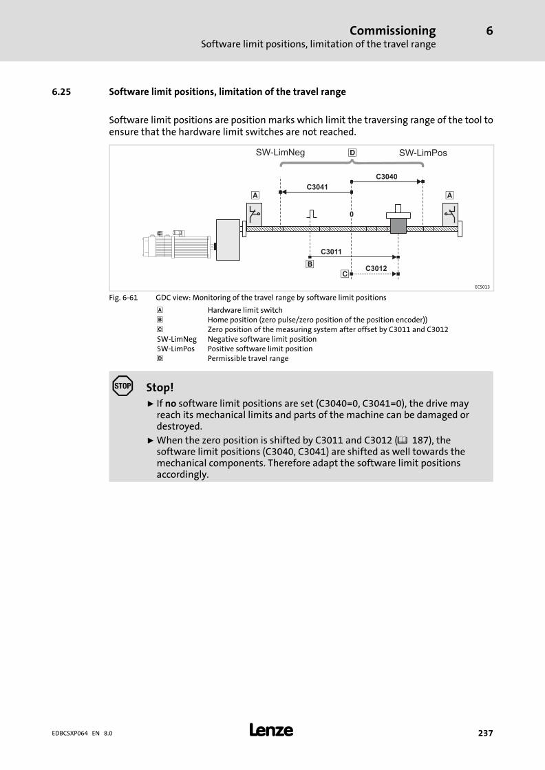
CommissioningSoftware limit positions, limitation of the travel range
6
� 237EDBCSXP064 EN 8.0
6.25 Software limit positions, limitation of the travel range
Software limit positions are position marks which limit the traversing range of the tool toensure that the hardware limit switches are not reached.
�
C3011
�
� C3012�
0
�
C3040
SW-LimPos
C3041
SW-LimNeg
ECS013
Fig. 6−61 GDC view: Monitoring of the travel range by software limit positions
Hardware limit switch� Home position (zero pulse/zero position of the position encoder))� Zero position of the measuring system after offset by C3011 and C3012SW−LimNeg Negative software limit positionSW−LimPos Positive software limit position� Permissible travel range
� Stop!
ƒ If no software limit positions are set (C3040=0, C3041=0), the drive mayreach its mechanical limits and parts of the machine can be damaged ordestroyed.
ƒ When the zero position is shifted by C3011 and C3012 (� 187), thesoftware limit positions (C3040, C3041) are shifted as well towards themechanical components. Therefore adapt the software limit positionsaccordingly.

CommissioningSoftware limit positions, limitation of the travel range
6
� 238 EDBCSXP064 EN 8.0
The software limit positions are set with C3040 (positive software limit position) andC3041 (negative software limit position) in the parameter menu under Positioning��Homing.
ƒ The software limit positions refer to the zero position.
ƒ Depending on the setting of the machine parameters, it may occur that the softwarelimit positions entered in C3040/C3041 in units cannot be displayed in internalincrements anymore. In this case, an internal limitation of the maximallydisplayable value is made automatically and the warning 2424("SWLimOutOfRange") is output. The currently effective values of the positive andnegative software limit positions are displayed in C4240/C4241.
ƒ Consider an appropriate back−up distance when selecting the software limitpositions which ensures that the software limit positions will not be reached even incase of slight variations of the actual position values in correct positioningprocesses.
ƒ The acceptance of new settings in C3034/C3041 requires a status change to"Stand−by"!
ƒ The value for the positive software limit position must be greater than the value forthe negative software limit position (C3040 > C3041). Otherwise FAIL−QSP (faultnumber 3417, "InvSftwLimits") is activated and the drive changes to "Trouble".
ƒ If the home position is known in the "Continuous constant travel" mode(C3095/x = 2) and if a software limit position is reached, FAIL−QSP is activated:
– Fault no. 3402, "PosPosLimit"
– Fault no. 3403, "NegPosLimit"
(For manual jog (inching mode) instead of FAIL−QSP a corresponding warning (fault no.2402, 2403) is actuated.)
ƒ If the software limit positions are overtravelled, status bit Stat2.SWLimErr is set to 1in C4046.
Code Possible settings IMPORTANT
No. Designation Lenze/{Appl.}
Selection
C3040 SW−LimPos 3600.0 Positive software limit position � 237
0.0000 {0.0001units}
214000.0000
C3041 SW−LimNeg −3600.0 Negative software limit position � 237
−214000.0000 {0.0001units}
0.0000
C3042 SWLimCtrlMode
0 Mode of the software limitposition monitoring
0 Current setpoint position +defined direction of movement
1 Current actual position
C4265 MaxTargetInp Max. target position input (inunits)Read only
� 103
−214000.0000 {0.0001units}
214000.0000

CommissioningSoftware limit positions, limitation of the travel range
6
� 239EDBCSXP064 EN 8.0
Operating mode of the software limit position monitoring
Before positioning is started, the software limit position monitoring checks if the targetposition is within the valid traversing range defined by the software limit positions. If thisis not the case, positioning is not started and a fault message is indicated.
If the current position is beyond the software limit positions, the defined direction ofmovement of the drive is checked in addition to the position in case of a setpoint−basedmonitoring of the software limit positions (C3042 = 0) . If the drive stands still or if the toolis to move towards the permissible traversing range, no fault is triggered. Only if the toolis to travel further away from the permissible traversing range, a fault message is outputand a QSP is activated.
With the actual value−based monitoring of the software limit positions (C3042 = 1), thecurrent actual position of the drive is checked. If the current actual position is beyond thepermissible traversing range, a fault message is output and a QSP is activated. When thefault message is triggered, the status changes to "Trouble".
In "ManualJog" the software limit positions cannot be exceeded because the drivetraverses to the software limit positions.
When is the software limit position monitoring deactivated?
The monitoring of the software limit positions is deactivated if:
ƒ Both software limit positions (C3040/C3041) are set to "0".
ƒ Homing is executed.
ƒ Status bit Stat1.HomePosAvailable = 0 (home position not known.)
CommissioningEvaluation of hardware limit switches
6
� 240 EDBCSXP064 EN 8.0
6.26 Evaluation of hardware limit switches
ƒ Ensure a fail−safe design of the hardware limit switches (NC contact, LOW active).
ƒ The active level is set via C0114/x (polarity of the digital inputs).
ƒ If a hardware limit switch is approached, the drive brakes to standstill via the quickstop deceleration time set and FAIL−QSP is actuated.
– Fault No. 3400, "PosLimitSw"
– Fault No. 3401, "NegLimitSw"
The drive changes to the "Trouble" state.
ƒ The quick stop deceleration time is set with C0105 in the GDC parameter menuunder Positioning/E−Shaft�� Machine parameters.
CommissioningController enable (CINH = 0)
6
� 241EDBCSXP064 EN 8.0
6.27 Controller enable (CINH = 0)
The controller will only be enabled internally if no signal sources relevant for the controllerinhibit (CINH) are activated (i.e. CINH−signal sources = 0).
The following table describes the signal sources for the controller inhibit (CINH) /controller enable:
Source of theController inhibit
Controllerinhibit
Controllerenable
Comment
Terminal X6/SI1(Controller inhibit)
LOW level(0 ... +4 V)
HIGH level(+13 ... +30 V)
For controller enable, both input terminals(X6/SI1 AND X6/SI2) must be controlledwith HIGH level.Terminal X6/SI2
(Pulse inhibit)LOW level(0 ... +4 V)
HIGH level(+13 ... +30 V)
Control bit Ctrl1.Cinhin the control word"Ctrl1"
Ctrl1.Cinh = 1 Ctrl1.Cinh = 0 see � 158The control word "Ctrl1" is described via theset control interface.The control interface is selected underC4010. The following are available:� MotionBus (CAN)� System bus (CAN−AUX)� Fieldbus via AIF interface� Code C4040If required, see the documentation on thecorresponding fieldbus module, if controlvia AIF interface.
C0040(Controller inhibit)
C0040 = 0 C0040 = 1
STOP/RUN key onthe operatingmodule/keypad XT
" key # key Inhibiting with " key is only possible ifthe " key is assigned with "CINH" viaC0469.Set C0135.Bit09 = 1 via the " key.Set C0135.Bit09 = 0 via the # key.
Fault/message � in case of TRIP� in case of
message
TRIP−RESET For check see � 337.
Control bit09(controller inhibitCINH) in the "DCTRLcontrol word" underC0135
C0135.Bit09 = 1 C0135.Bit09 = 0
Function button<F8> and <F9> in theGlobal Drive Control(GDC)
Button <F8> Button <F9> GDC writes to C0135.Bit09 via parameterdata channel.<F8> (start drive) serves to setC0135.Bit09 = 1.<F9> (stop drive) serves to setC0135.Bit09 = 0.
Brake logic CINH is controlledinternally by brakelogic
CINH is notcontrolled internallyby brake logic
Display through C0183 = 122(CINH−intern1 (brake logic))
CommissioningController enable (CINH = 0)
6
� 242 EDBCSXP064 EN 8.0
The following table describes the status displays for the controller inhibit (Cinh) /controller enable:
Status display Controller inhibited Enable controller Comment
Green LED Blinking Constantly ON
C0183 drivediagnostics
Display of the signalsource for controllerinhibit (Cinh)
Display "OK" See GDC menu "Diagnostics / Devicecurrent status" or GDC monitor windowdown right
C0150 DCTRL statusword Bit 7 (CINHactive)
C0150.Bit07 = 1 C0150.Bit07 = 0 See GDC menu "Diagnostics / displayMCTRL"
Keypad text display"IMP"
"IMP" "IMP" not displayed
� Note!
All signal sources for controller inhibit (Cinh) act like a series connection ofswitches which are independent of each other.
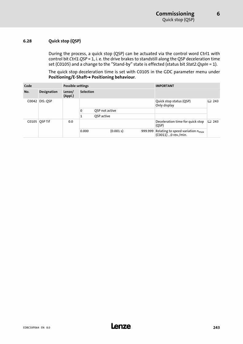
CommissioningQuick stop (QSP)
6
� 243EDBCSXP064 EN 8.0
6.28 Quick stop (QSP)
During the process, a quick stop (QSP) can be actuated via the control word Ctrl1 withcontrol bit Ctrl1.QSP = 1, i. e. the drive brakes to standstill along the QSP deceleration timeset (C0105) and a change to the "Stand−by" state is effected (status bit Stat2.QspIn = 1).
The quick stop deceleration time is set with C0105 in the GDC parameter menu underPositioning/E−Shaft� Positioning behaviour.
Code Possible settings IMPORTANT
No. Designation Lenze/{Appl.}
Selection
C0042 DIS: QSP Quick stop status (QSP)Only display
� 243
0 QSP not active
1 QSP active
C0105 QSP Tif 0.0 Deceleration time for quick stop(QSP)
� 243
0.000 {0.001 s} 999.999 Relating to speed variation nmax(C0011) ...0 rev./min.
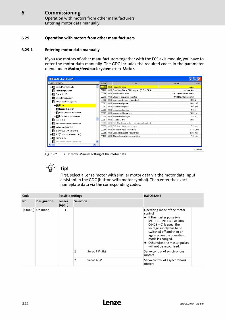
CommissioningOperation with motors from other manufacturersEntering motor data manually
6
� 244 EDBCSXP064 EN 8.0
6.29 Operation with motors from other manufacturers
6.29.1 Entering motor data manually
If you use motors of other manufacturers together with the ECS axis module, you have toenter the motor data manually. The GDC includes the required codes in the parametermenu under Motor/feedback systems��� Motor.
ECSXA458
Fig. 6−62 GDC view: Manual setting of the motor data
� Tip!
First, select a Lenze motor with similar motor data via the motor data inputassistant in the GDC (button with motor symbol). Then enter the exactnameplate data via the corresponding codes.
Code Possible settings IMPORTANT
No. Designation Lenze/{Appl.}
Selection
[C0006] Op mode 1 Operating mode of the motorcontrol� If the master pulse (via
MCTRL: C0911 = 0 or DfIn:C0428 = 0) is used, thevoltage supply has to beswitched off and then onagain when the operatingmode is changed.
� Otherwise, the master pulseswill not be recognised.
1 Servo PM−SM Servo control of synchronousmotors
2 Servo ASM Servo control of asynchronousmotors
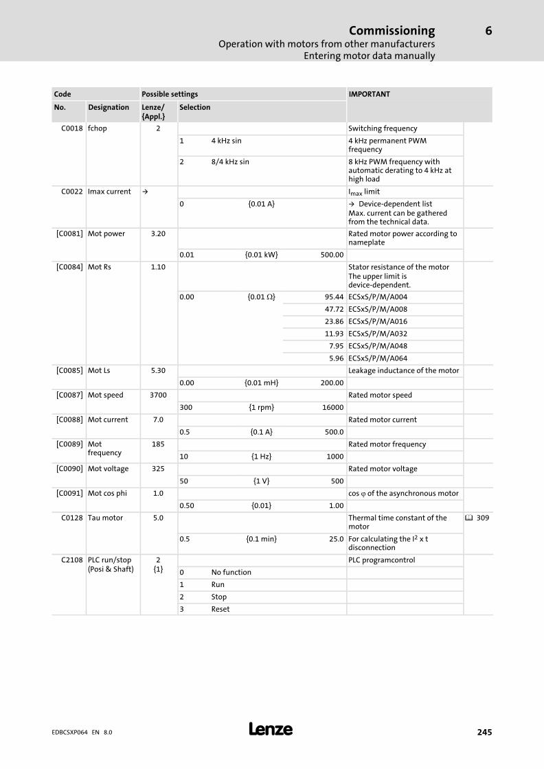
CommissioningOperation with motors from other manufacturers
Entering motor data manually
6
� 245EDBCSXP064 EN 8.0
IMPORTANTPossible settingsCode
SelectionLenze/{Appl.}
DesignationNo.
C0018 fchop 2 Switching frequency
1 4 kHz sin 4 kHz permanent PWMfrequency
2 8/4 kHz sin 8 kHz PWM frequency withautomatic derating to 4 kHz athigh load
C0022 Imax current � Imax limit
0 {0.01 A} � Device−dependent listMax. current can be gatheredfrom the technical data.
[C0081] Mot power 3.20 Rated motor power according tonameplate
0.01 {0.01 kW} 500.00
[C0084] Mot Rs 1.10 Stator resistance of the motorThe upper limit isdevice−dependent.
0.00 {0.01 �} 95.44 ECSxS/P/M/A004
47.72 ECSxS/P/M/A008
23.86 ECSxS/P/M/A016
11.93 ECSxS/P/M/A032
7.95 ECSxS/P/M/A048
5.96 ECSxS/P/M/A064
[C0085] Mot Ls 5.30 Leakage inductance of the motor
0.00 {0.01 mH} 200.00
[C0087] Mot speed 3700 Rated motor speed
300 {1 rpm} 16000
[C0088] Mot current 7.0 Rated motor current
0.5 {0.1 A} 500.0
[C0089] Motfrequency
185 Rated motor frequency
10 {1 Hz} 1000
[C0090] Mot voltage 325 Rated motor voltage
50 {1 V} 500
[C0091] Mot cos phi 1.0 cos � of the asynchronous motor
0.50 {0.01} 1.00
C0128 Tau motor 5.0 Thermal time constant of themotor
� 309
0.5 {0.1 min} 25.0 For calculating the I2 x tdisconnection
C2108 PLC run/stop(Posi & Shaft)
2{1}
PLC programcontrol
0 No function
1 Run
2 Stop
3 Reset
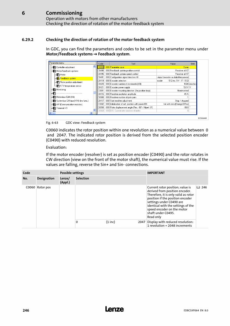
CommissioningOperation with motors from other manufacturersChecking the direction of rotation of the motor feedback system
6
� 246 EDBCSXP064 EN 8.0
6.29.2 Checking the direction of rotation of the motor feedback system
In GDC, you can find the parameters and codes to be set in the parameter menu underMotor/Feedback systems � Feedback system.
ECSXA449
Fig. 6−63 GDC view: Feedback system
C0060 indicates the rotor position within one revolution as a numerical value between 0�and �2047. The indicated rotor position is derived from the selected position encoder(C0490) with reduced resolution.
Evaluation:
If the motor encoder (resolver) is set as position encoder (C0490) and the rotor rotates inCW direction (view on the front of the motor shaft), the numerical value must rise. If thevalues are falling, reverse the Sin+ and Sin− connections.
Code Possible settings IMPORTANT
No. Designation Lenze/{Appl.}
Selection
C0060 Rotor pos Current rotor position; value isderived from position encoder.Therefore, it is only valid as rotorposition if the position encodersettings under C0490 areidentical with the settings of thespeed encoder on the motorshaft under C0495.Read only
� 246
0 {1 inc} 2047 Display with reduced resolution:1 revolution = 2048 increments
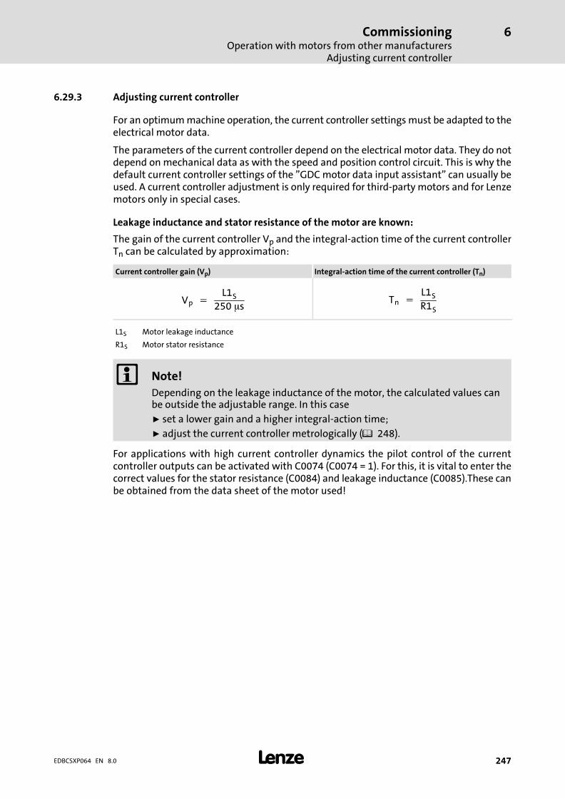
CommissioningOperation with motors from other manufacturers
Adjusting current controller
6
� 247EDBCSXP064 EN 8.0
6.29.3 Adjusting current controller
For an optimum machine operation, the current controller settings must be adapted to theelectrical motor data.
The parameters of the current controller depend on the electrical motor data. They do notdepend on mechanical data as with the speed and position control circuit. This is why thedefault current controller settings of the "GDC motor data input assistant" can usually beused. A current controller adjustment is only required for third−party motors and for Lenzemotors only in special cases.
Leakage inductance and stator resistance of the motor are known:
The gain of the current controller Vp and the integral−action time of the current controllerTn can be calculated by approximation:
Current controller gain (Vp) Integral−action time of the current controller (Tn)
Vp� ��L1S
250��sTn� ��
L1S
R1S
L1S Motor leakage inductance
R1S Motor stator resistance
� Note!
Depending on the leakage inductance of the motor, the calculated values canbe outside the adjustable range. In this case
ƒ set a lower gain and a higher integral−action time;
ƒ adjust the current controller metrologically (� 248).
For applications with high current controller dynamics the pilot control of the currentcontroller outputs can be activated with C0074 (C0074 = 1). For this, it is vital to enter thecorrect values for the stator resistance (C0084) and leakage inductance (C0085).These canbe obtained from the data sheet of the motor used!
CommissioningOperation with motors from other manufacturersAdjusting current controller
6
� 248 EDBCSXP064 EN 8.0
Leakage inductance and stator resistance of the motor are not known:
The current controller can be optimised metrologically with a current probe and anoscilloscope. For this, a test mode is available in which the current C0022 x �2 flows in phaseU after controller enable.
� Stop!
Avoid damage to the motor and machine
ƒ During the current controller adjustment, the motor must be freelyrotatable.
ƒ The test current must not exceed the maximum permissible motor current.
ƒ Always adjust the current controller at a switching frequency of 8 kHz.
Observe the current step in phase U to adjust the current controller.
Setting sequence
1. Select 8 kHz as switching frequency (C0018 = 2).
2. Select the test current under C0022:
– Start with a low current value, e.g. half the rated motor current.
3. Activate the test mode with C0418 = 1.
4. Enable the controller. (� 241)
– Adjust the synchronous motor.
– The asynchronous motor remains at standstill.
5. Enable and inhibit the controller several times in a row changing the currentcontroller gain (C0075) and the current controller adjustment time (C0076) suchthat the current characteristic is free of harmonics.
6. After the adjustment has been completed, deactivate the test mode with C0418 = 0.
7. If required, change the switching frequency under C0018.
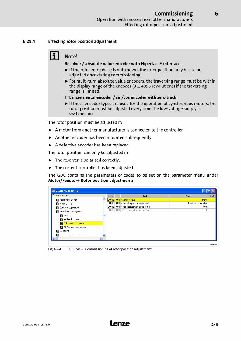
CommissioningOperation with motors from other manufacturers
Effecting rotor position adjustment
6
� 249EDBCSXP064 EN 8.0
6.29.4 Effecting rotor position adjustment
� Note!
Resolver / absolute value encoder with Hiperface® interface
ƒ If the rotor zero phase is not known, the rotor position only has to beadjusted once during commissioning.
ƒ For multi−turn absolute value encoders, the traversing range must be withinthe display range of the encoder (0 ... 4095 revolutions) if the traversingrange is limited.
TTL incremental encoder / sin/cos encoder with zero track
ƒ If these encoder types are used for the operation of synchronous motors, therotor position must be adjusted every time the low−voltage supply isswitched on.
The rotor position must be adjusted if:
ƒ A motor from another manufacturer is connected to the controller.
ƒ Another encoder has been mounted subsequently.
ƒ A defective encoder has been replaced.
The rotor position can only be adjusted if:
ƒ The resolver is polarised correctly.
ƒ The current controller has been adjusted.
The GDC contains the parameters or codes to be set on the parameter menu underMotor/Feedb. � Rotor position adjustment:
ECSXA464
Fig. 6−64 GDC view: Commissioning of rotor position adjustment
CommissioningOperation with motors from other manufacturersEffecting rotor position adjustment
6
� 250 EDBCSXP064 EN 8.0
Setting sequence
1. Inhibit controller. (� 241)
– Press the <F9> key in GDC.
– Green LED is blinking, red LED is off
2. Unload motor mechanically.
– Separate the motor from the gearbox or machine so that it can rotate freely.
3. Open holding brake (if available).
4. Activate rotor position adjustment with C0095 = 1.
5. Enable controller. (� 241)
– X6/SI1 = HIGH and X6/SI2 = HIGH and press the <F8> key in GDC.
The rotor position adjustment program of the controller is started:
– The rotor rotates half a revolution in 16 steps (for resolver with 1 pole pair:
180° electrically � 180° mechanically).
– After one revolution, C0095 is automatically reset to "0".
– The rotor zero phase is stored under C0058. (For absolute value encoders(Hiperface®, single−turn/multi−turn) at X8, C0058 is always "0".)
� Danger!
Uncontrolled drive movements after an Sd7 fault with absolute valueencoders
If absolute value encoders are used and the rotor position adjustment iscompleted with the fault message "Sd7" ( 343), the rotor position could notbe assigned to the feedback system. In this case, the drive may carry outuncontrolled movements after controller enable.
Possible consequences:
ƒ Death or severe injuries
ƒ The machine/drive may be destroyed or damaged
Protective measures:
ƒ Repeat rotor position adjustment (starting with step 1).
ƒ Check wiring and interference immunity of the encoder at X8.
6. Inhibit controller. (� 241)
– Press the <F9> key in GDC.
– Green LED is blinking, red LED is off
7. Save the data determined by the controller with C0003 = 1.
� Tip!
The values for C0058 and C0095 are only displayed in GDC if you place the barcursor on them and read back the code using function key <F6>.

CommissioningOperation with motors from other manufacturers
Effecting rotor position adjustment
6
� 251EDBCSXP064 EN 8.0
Code Possible settings IMPORTANT
No. Designation Lenze/{Appl.}
Selection
C0058 Rotor diff −90.0 Rotor displacement angle (offsetangle)Input in case of Lenze motor with� resolver: −90°� hiperface absolute value
encoder: 0°Code value is adapted by therotor position adjustmentfunction (C0095).Only relevant for the operationof synchronous motors.
� 249
−180.0 {0.1 �} 179.9
[C0095] Rotor pos adj 0 Activation of rotor positionadjustment for automaticdetermination of the rotordisplacement angle.C0058 displays the determinedrotor displacement angle (offsetangle).
� 249
0 Inactive
1 Active

CommissioningOptimising the drive behaviour after startSpeed controller adjustment
6
� 252 EDBCSXP064 EN 8.0
6.30 Optimising the drive behaviour after start
For applications with high current controller dynamics, the pilot control for the currentcontroller can be adjusted under C0074:
Code Possible settings IMPORTANT
No. Designation Lenze/{Appl.}
Selection
C0074 Dynamics 0 Pilot control of the currentcontroller for higher dynamics
� 247
0 Normal
1 Enhanced
6.30.1 Speed controller adjustment
The speed controller of the ECS is designed as an ideal PID controller.
Conditions for the speed controller adjustment:
ƒ The speed controller can only be set correctly when the system constellation hasbeen completed.
ƒ The current controller is set correctly (given with a Lenze motor and setting viamotor data input assistant in the GDC) .
ƒ The PE connection of the axis module is sufficient so that the actual values are not"noisy".
ƒ There are as few as possible elasticity and backlash between drive and load.
ƒ The maximum current C0022 and the maximum speed C0011 are set to the valuesrequired for the operation. Due to the scaling of the input and output variables ofthe speed controller, C0011 and C0022 have an impact on the controller settings.
ƒ The time constant for the actual speed value filter C0497 is set to the required value(usually remains in default setting).
In GDC, you can find the codes for adjusting the speed controller in the parameter menuunder Controller settings�� Speed/position.
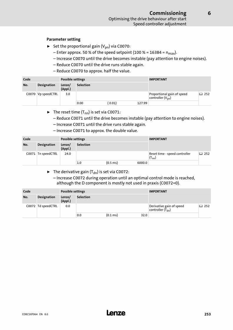
CommissioningOptimising the drive behaviour after start
Speed controller adjustment
6
� 253EDBCSXP064 EN 8.0
Parameter setting
ƒ Set the proportional gain (Vpn) via C0070:
– Enter approx. 50 % of the speed setpoint (100 % = 16384 = nmax).
– Increase C0070 until the drive becomes instable (pay attention to engine noises).
– Reduce C0070 until the drive runs stable again.
– Reduce C0070 to approx. half the value.
Code Possible settings IMPORTANT
No. Designation Lenze/{Appl.}
Selection
C0070 Vp speedCTRL 3.0 Proportional gain of speedcontroller (Vpn)
� 252
0.00 { 0.01} 127.99
ƒ The reset time (Tnn) is set via C0071:
– Reduce C0071 until the drive becomes instable (pay attention to engine noises).
– Increase C0071 until the drive runs stable again.
– Increase C0071 to approx. the double value.
Code Possible settings IMPORTANT
No. Designation Lenze/{Appl.}
Selection
C0071 Tn speedCTRL 24.0 Reset time − speed controller(Tnn)
� 252
1.0 {0.5 ms} 6000.0
ƒ The derivative gain (Tdn) is set via C0072:
– Increase C0072 during operation until an optimal control mode is reached,although the D component is mostly not used in praxis (C0072=0).
Code Possible settings IMPORTANT
No. Designation Lenze/{Appl.}
Selection
C0072 Td speedCTRL 0.0 Derivative gain of speedcontroller (Tdn)
� 252
0.0 {0.1 ms} 32.0
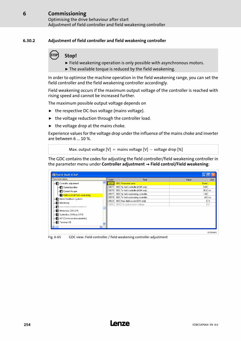
CommissioningOptimising the drive behaviour after startAdjustment of field controller and field weakening controller
6
� 254 EDBCSXP064 EN 8.0
6.30.2 Adjustment of field controller and field weakening controller
� Stop!
ƒ Field weakening operation is only possible with asynchronous motors.
ƒ The available torque is reduced by the field weakening.
In order to optimise the machine operation in the field weakening range, you can set thefield controller and the field weakening controller accordingly.
Field weakening occurs if the maximum output voltage of the controller is reached withrising speed and cannot be increased further.
The maximum possible output voltage depends on
ƒ the respective DC−bus voltage (mains voltage).
ƒ the voltage reduction through the controller load.
ƒ the voltage drop at the mains choke.
Experience values for the voltage drop under the influence of the mains choke and inverterare between 6 ... 10 %.
Max.�output�voltage�[V] � mains�voltage�[V] � voltage�drop�[%]
The GDC contains the codes for adjusting the field controller/field weakening controller inthe parameter menu under Controller adjustment�� Field control/Field weakening:
ECSXA463
Fig. 6−65 GDC view: Field controller / field weakening controller adjustment

CommissioningOptimising the drive behaviour after start
Adjustment of field controller and field weakening controller
6
� 255EDBCSXP064 EN 8.0
6.30.2.1 Adjusting the field controller
The field controller settings depend on the motor data.
Setting sequence
1. Stop the PLC program: C2108 = 2
– As of operating system version 7.0 (see nameplate), this is no longer necessary,because C0006 (see 2.) can also be written when the PLC program is running!
2. Set motor control for asynchronous motors: C0006 = 2
– The motor nameplate data must be entered correctly!
3. Read rotor time constant Tr (C0083).
4. Read magnetising current Id (C0092).
5. Calculate field controller gain VpF and enter in C0077.
VpF� ��Tr�(C0083) � Id�(C0092)
875��s � Imax
Imax Maximum current of axis module
6. Enter rotor time constant Tr as field controller integral−action time TnF in C0078.

CommissioningOptimising the drive behaviour after startAdjustment of field controller and field weakening controller
6
� 256 EDBCSXP064 EN 8.0
6.30.2.2 Field weakening controller adjustment
ƒ The field weakening controller determines the speed performance of theasynchronous motor in the field weakening range.
ƒ The field weakening controller can only be set correctly when the systemconstellation has been completed and is under load.
� Note!
An excessive value of Imax (C0022) can cause a malfunction of the drive in thefield weakening range of the asynchronous motor. For this reason, the currentis limited in terms of speed in the field weakening range. The limitation has a1/n characteristic and is derived from the motor parameters.
The limitation can be adjusted with the stator leakage inductance (C0085):
ƒ Low values cause a limitation at higher speeds.
ƒ Higher values cause a limitation at lower speeds.
Setting sequence
1. Set gain Vp: C0577 = 0.01 ... 0.99
– Vp must not be "0" (deactivates the field weakening controller)!
2. Set integral−action time Tn: C0578 = 1 ... 40 ms
3. Select a speed setpoint so that the motor is operated in the field weakening range.
4. Observe the speed curve
– If the speed takes an irregular course, the field weakening controller must bereadjusted.
– The field weakening controller must be provided with a distinct integral action.
� Tip!
Parameter setting with a distinct I component can improve the drivebehaviour when changing to the field weakening range.
For this purpose, set the gain (Vp) in C0577 to at least 0.01.
The following applies:
ƒ P component = Vp = C0577
ƒ I component = VI = C0577/C0578
If the P component (Vp) is reduced via C0577, adapt the reset time C0578accordingly to keep the I component (VI).
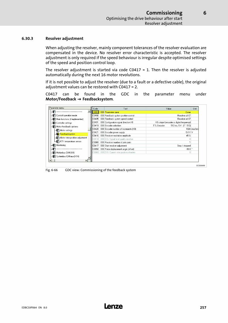
CommissioningOptimising the drive behaviour after start
Resolver adjustment
6
� 257EDBCSXP064 EN 8.0
6.30.3 Resolver adjustment
When adjusting the resolver, mainly component tolerances of the resolver evaluation arecompensated in the device. No resolver error characteristic is accepted. The resolveradjustment is only required if the speed behaviour is irregular despite optimised settingsof the speed and position control loop.
The resolver adjustment is started via code C0417 = 1. Then the resolver is adjustedautomatically during the next 16 motor revolutions.
If it is not possible to adjust the resolver (due to a fault or a defective cable), the originaladjustment values can be restored with C0417 = 2.
C0417 can be found in the GDC in the parameter menu underMotor/Feedback���Feedbacksystem.
ECSXA449
Fig. 6−66 GDC view: Commissioning of the feedback system

Parameter settingGeneral information
7
� 258 EDBCSXP064 EN 8.0
7 Parameter setting
7.1 General information
ƒ Controllers and power supply modules can be adapted to your application by settingthe parameters. A detailed description of the functions can be found in the chapter"Commissioning" ( 92).
ƒ The parameters for the functions are stored in numbered codes:
– The codes are marked in the text with a "C".
– The code table in the appendix ( 353) provides a quick overview of all codes. Thecodes are sorted in numerical ascending order, thus serving as a "reference book".
Parameter setting with XT keypad or PC/laptop
Detailed information on parameter setting with the XT keypad can be found in thefollowing chapters.
� Detailed information ...
on the parameterisation by means of a PC/laptop can be found in thedocumentation for the "Global Drive Control" (GDC) parameterisation andoperating program.
In addition to parameter setting, the XT keypad or PC/laptop serves to:
ƒ Control the controller (e. g. inhibiting or enabling)
ƒ Select the setpoints
ƒ Display operating data
ƒ Transfer parameter sets to other controllers (only with PC/laptop).
Parameter setting with a bus system
� Detailed information ...
on the parameterisation with a bus system can be found in thedocumentation of the communication module to be applied ( 432).
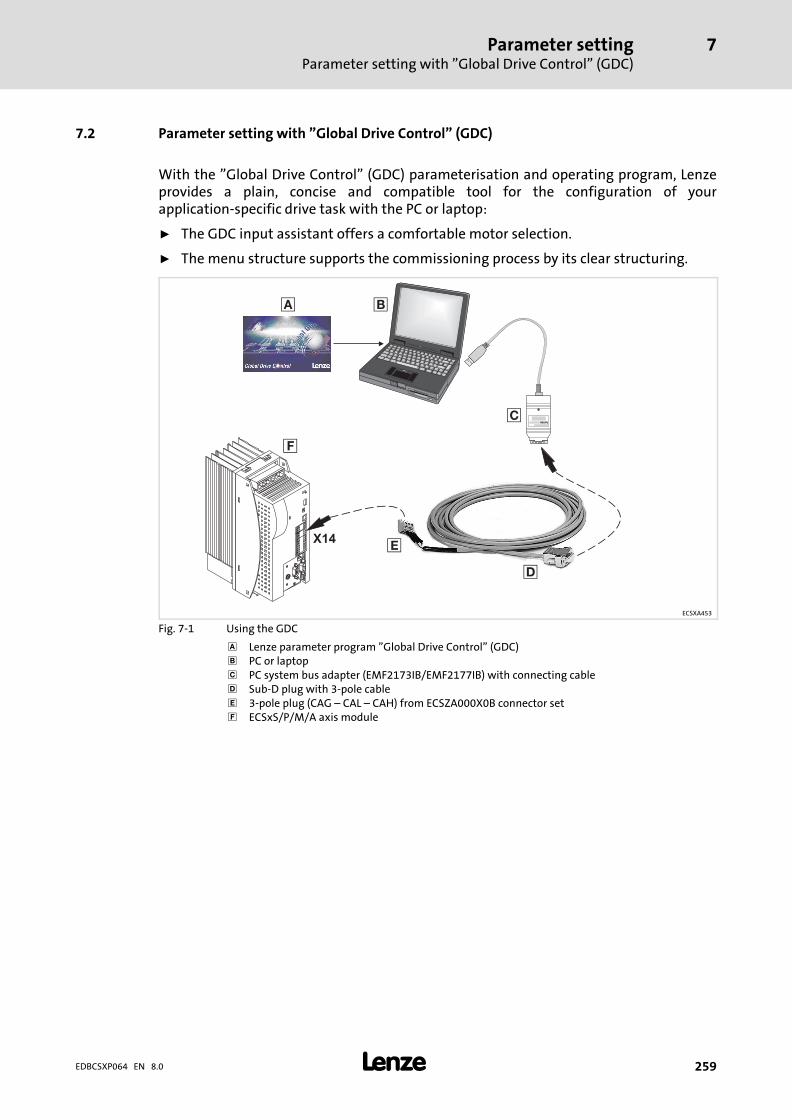
Parameter settingParameter setting with "Global Drive Control" (GDC)
7
� 259EDBCSXP064 EN 8.0
7.2 Parameter setting with "Global Drive Control" (GDC)
With the "Global Drive Control" (GDC) parameterisation and operating program, Lenzeprovides a plain, concise and compatible tool for the configuration of yourapplication−specific drive task with the PC or laptop:
ƒ The GDC input assistant offers a comfortable motor selection.
ƒ The menu structure supports the commissioning process by its clear structuring.
X14
� �
L
�
�
�
ECSXA453
Fig. 7−1 Using the GDC
Lenze parameter program "Global Drive Control" (GDC)� PC or laptop� PC system bus adapter (EMF2173IB/EMF2177IB) with connecting cable� Sub−D plug with 3−pole cable� 3−pole plug (CAG ˘ CAL ˘ CAH) from ECSZA000X0B connector set� ECSxS/P/M/A axis module
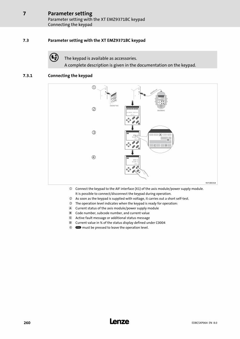
Parameter settingParameter setting with the XT EMZ9371BC keypadConnecting the keypad
7
� 260 EDBCSXP064 EN 8.0
7.3 Parameter setting with the XT EMZ9371BC keypad
� The keypad is available as accessories.
A complete description is given in the documentation on the keypad.
7.3.1 Connecting the keypad
�
��
�
�
�
�
�
�
�
��
���
SHPRG Pa
raCode
Menu 00
5000
50.00_Hz
MCTRL-NOUT
E82ZWLxxx
� ��
� � �
� �
� �����SHPRG
Para
Code
Menu
0050 00
50.00_Hz
M C T R L - N O U T
E82ZBBXC
EMZ9371BC
� ��
� � �
� �
� �����SHPRG
Para
Code
Menu
0050 00
G L O B A L D R I V E
I n i t
� ��
� � �
� �
�
0050 00
50.00 Hz
2 0 %
� ��
� � �
� �
�
0050 00
50.00 Hz
2 0 %
�
�
�� ���� �
�
� �
9371BC018
� Connect the keypad to the AIF interface (X1) of the axis module/power supply module.
It is possible to connect/disconnect the keypad during operation.
� As soon as the keypad is supplied with voltage, it carries out a short self−test.
� The operation level indicates when the keypad is ready for operation:
Current status of the axis module/power supply module
� Code number, subcode number, and current value
� Active fault message or additional status message
� Current value in % of the status display defined under C0004
� must be pressed to leave the operation level.

Parameter settingParameter setting with the XT EMZ9371BC keypad
Description of the display elements
7
� 261EDBCSXP064 EN 8.0
7.3.2 Description of the display elements
� ��
� � �
� �
� �����SHPRG
Para
Code
Menu
0050 00
50.00_Hz
M C T R L - N O U T
��
�
��
�
�
9371BC002
Fig. 7−2 Keypad front view
Status displays
Display Meaning Explanation
$ Ready for operation
% Pulse inhibit active Power outputs inhibited
& Adjusted current limitation is exceeded inmotor mode or generator mode
' Speed controller 1 within its limitation � Drive is torque−controlled� Only active for operation with Lenze
devices of the 9300 series!
( Active fault
� Parameter acceptance
Display Meaning Explanation
) Parameter is accepted �immediately � The device immediately operates with thenew parameter value.
SHPRG ) The parameter must be confirmed with �
The device operates with the newparameter value after being confirmed.
SHPRG When the controller is inhibited, theparameter must be confirmed with �
The device operates with the newparameter value after the controller hasbeen released again.
None Display parameters Cannot be changed.
� Active level
Display Meaning Explanation
Menu Active menu level � Selection of main menu and submenus� No menu for ECSxE power supply
module
Code Active code level Selection of codes and subcodes
Para Active parameter level Change of parameters in the codes orsubcodes
None Active operating level Display of operating parameters
� Short text
Display Meaning Explanation
Alphanumerical Contents of the menus, meaning of the codesand parameters
Display of C0004 in % and the active fault inthe operating level

Parameter settingParameter setting with the XT EMZ9371BC keypadDescription of the display elements
7
� 262 EDBCSXP064 EN 8.0
� Number
Active level Meaning Explanation
Menu level Menu number � Display is only active when operatingLenze devices of the 8200 vector or8200 motec series.
� No menu for ECSxE power supplymodule
Code level Four−digit code number
� Number
Active level Meaning Explanation
Menu level Submenu number � Display is only active when operatingLenze devices of the 8200 vector or8200 motec series.
� No menu for ECSxE power supplymodule
Code level Two−digit subcode number
� Parameter value
Parameter value with unit
� Cursor
The figure over the cursor can be changed directly in the parameter level.
� Function keys
For description see the following table.
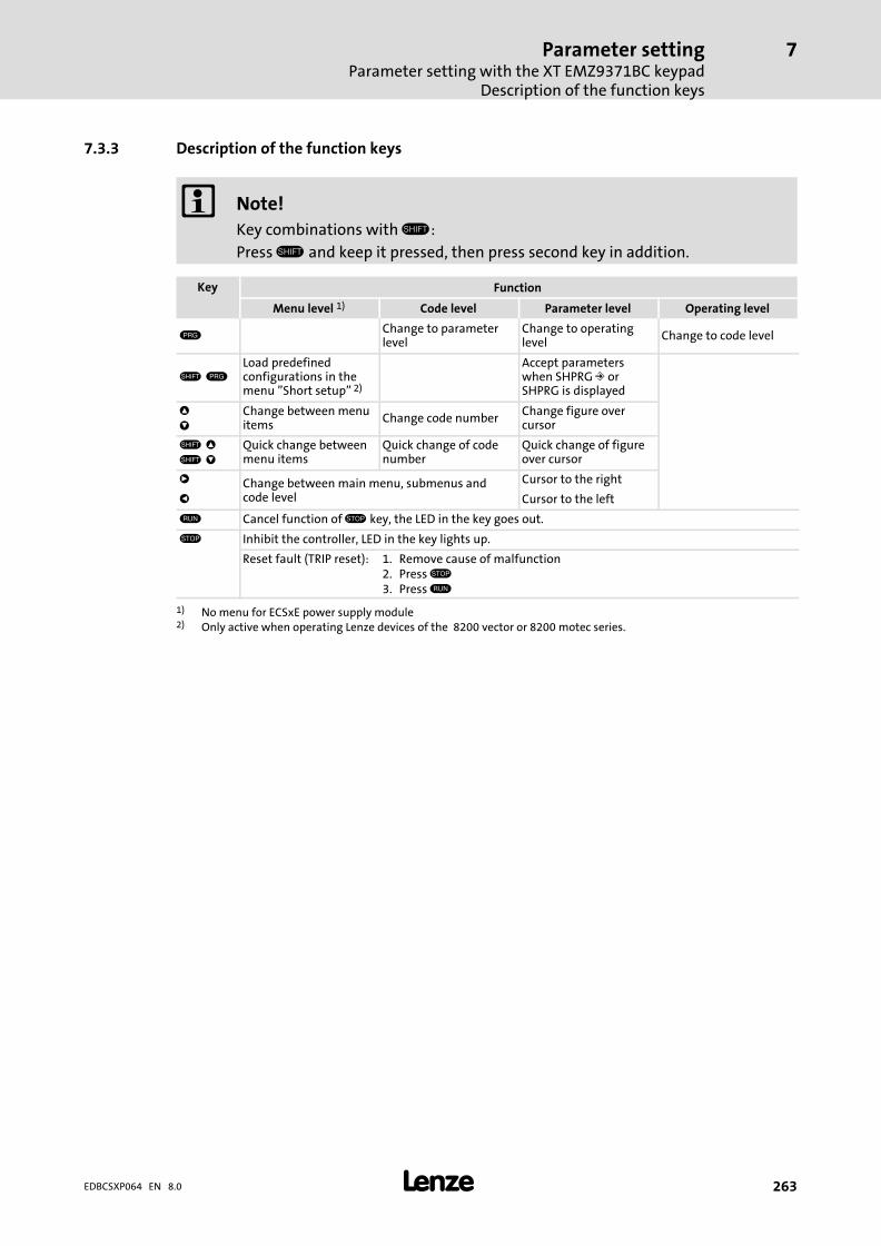
Parameter settingParameter setting with the XT EMZ9371BC keypad
Description of the function keys
7
� 263EDBCSXP064 EN 8.0
7.3.3 Description of the function keys
� Note!
Key combinations with �:
Press � and keep it pressed, then press second key in addition.
Key Function
Menu level 1) Code level Parameter level Operating level
Change to parameterlevel
Change to operatinglevel
Change to code level
� Load predefinedconfigurations in themenu "Short setup" 2)
Accept parameterswhen SHPRG ) orSHPRG is displayed
*
+
Change between menuitems
Change code numberChange figure overcursor
� *
� +
Quick change betweenmenu items
Quick change of codenumber
Quick change of figureover cursor
, Change between main menu, submenus andcode level
Cursor to the right
- Cursor to the left
. Cancel function of / key, the LED in the key goes out.
/ Inhibit the controller, LED in the key lights up.
Reset fault (TRIP reset): 1. Remove cause of malfunction2. Press /3. Press .
1) No menu for ECSxE power supply module2) Only active when operating Lenze devices of the 8200 vector or 8200 motec series.
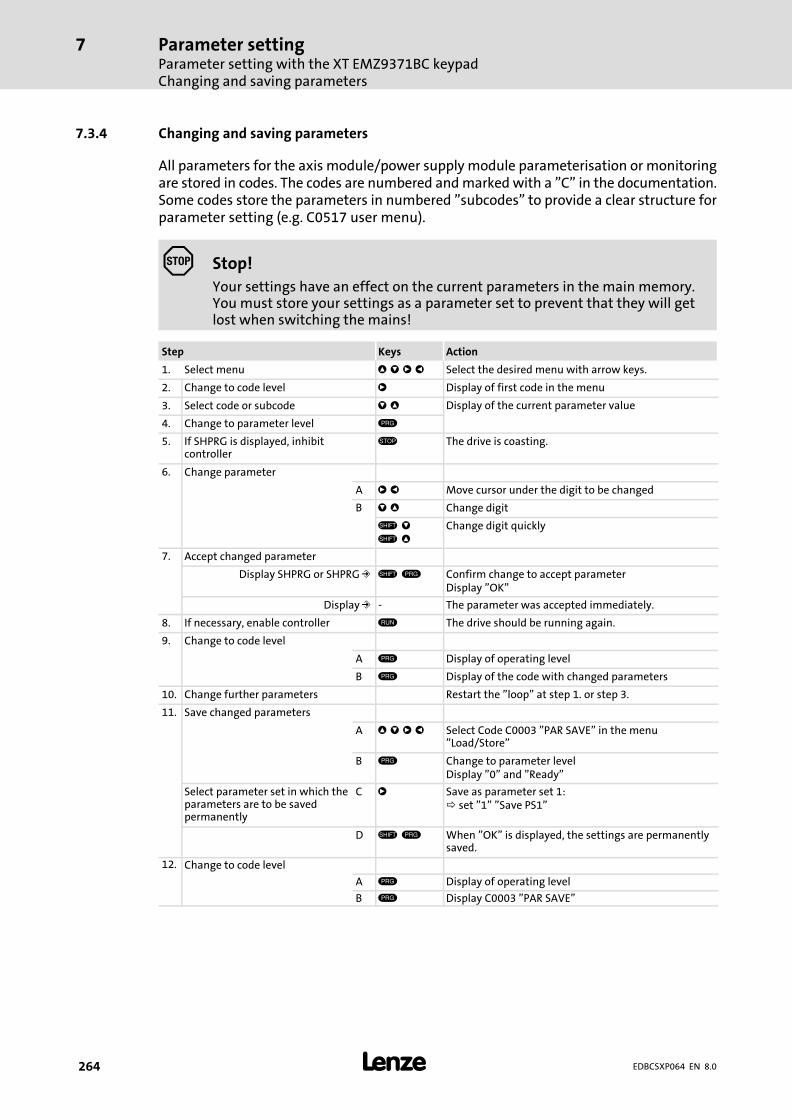
Parameter settingParameter setting with the XT EMZ9371BC keypadChanging and saving parameters
7
� 264 EDBCSXP064 EN 8.0
7.3.4 Changing and saving parameters
All parameters for the axis module/power supply module parameterisation or monitoringare stored in codes. The codes are numbered and marked with a "C" in the documentation.Some codes store the parameters in numbered "subcodes" to provide a clear structure forparameter setting (e.g. C0517 user menu).
� Stop!
Your settings have an effect on the current parameters in the main memory.You must store your settings as a parameter set to prevent that they will getlost when switching the mains!
Step Keys Action
1. Select menu * + , - Select the desired menu with arrow keys.
2. Change to code level , Display of first code in the menu
3. Select code or subcode + * Display of the current parameter value
4. Change to parameter level
5. If SHPRG is displayed, inhibitcontroller
/ The drive is coasting.
6. Change parameter
A , - Move cursor under the digit to be changed
B + * Change digit
� +
� *
Change digit quickly
7. Accept changed parameter
Display SHPRG or SHPRG ) � Confirm change to accept parameterDisplay "OK"
Display ) − The parameter was accepted immediately.
8. If necessary, enable controller . The drive should be running again.
9. Change to code level
A Display of operating level
B Display of the code with changed parameters
10. Change further parameters Restart the "loop" at step 1. or step 3.
11. Save changed parameters
A * + , - Select Code C0003 "PAR SAVE" in the menu"Load/Store"
B Change to parameter levelDisplay "0" and "Ready"
Select parameter set in which theparameters are to be savedpermanently
C , Save as parameter set 1: set "1" "Save PS1"
D � When "OK" is displayed, the settings are permanentlysaved.
12. Change to code level
A Display of operating level
B Display C0003 "PAR SAVE"
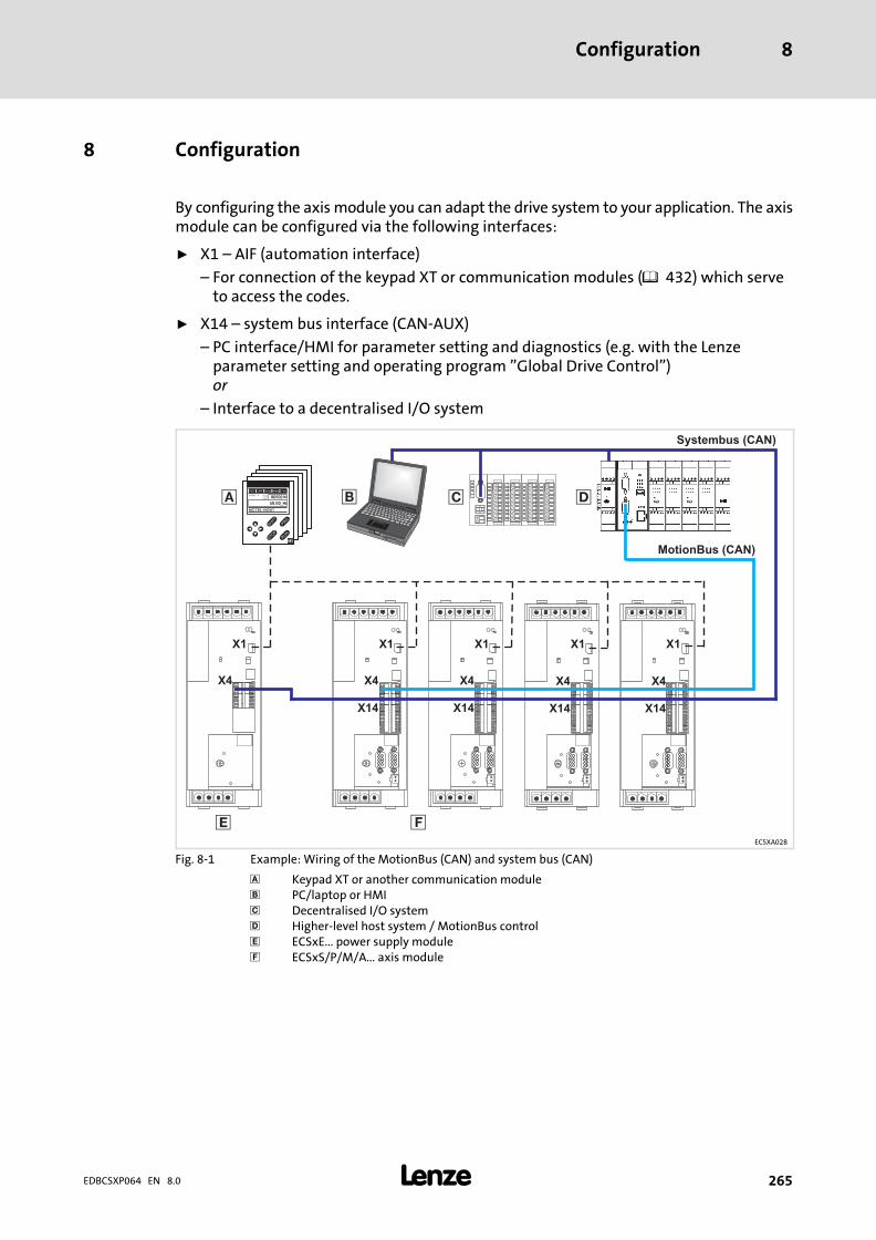
Configuration 8
� 265EDBCSXP064 EN 8.0
8 Configuration
By configuring the axis module you can adapt the drive system to your application. The axismodule can be configured via the following interfaces:
ƒ X1 ˘ AIF (automation interface)
– For connection of the keypad XT or communication modules (� 432) which serveto access the codes.
ƒ X14 ˘ system bus interface (CAN−AUX)
– PC interface/HMI for parameter setting and diagnostics (e.g. with the Lenzeparameter setting and operating program "Global Drive Control")or
– Interface to a decentralised I/O system
X4
�
X4
X14
X4
X14
X4
X14
Systembus (CAN)
MotionBus (CAN)
� ��
� � �
� �
� �����SHPRG
Para
Code
Menu
0050 00
50.00_Hz
MCTRL-NOUT
X1 X1
X4
X14
X1 X1
� � �
X1
�
ECSXA028
Fig. 8−1 Example: Wiring of the MotionBus (CAN) and system bus (CAN)
Keypad XT or another communication module� PC/laptop or HMI� Decentralised I/O system� Higher−level host system / MotionBus control� ECSxE... power supply module� ECSxS/P/M/A... axis module
ConfigurationConfiguring MotionBus/system bus (CAN)Setting CAN node address and baud rate
8
� 266 EDBCSXP064 EN 8.0
8.1 Configuring MotionBus/system bus (CAN)
� Note!
System bus (CAN)
The ECSxA... axis module can communicate with a higher−level host system(PLC) or further controllers via both CAN interfaces (X4 or X14).
MotionBus (CAN)
The "MotionBus (CAN)" term expresses the functionality of the CAN interfaceX4 in case of ECSxS/P/M... axis modules, where communication takes placeusing a higher−level host system (PLC) or further controllers exclusively via theX4 interface. Interface X14 (CAN−AUX) is exclusively used for parameter settingand diagnostics.
� Note!
In case of the ECSxP axis module, the PDOs CANaux1_IN/OUT andCANaux2_IN/OUT can be used via the CAN interface X14 (system bus (CAN)).Configuration takes place via codes C24xx.
� Tip!
More detailed information on the CAN bus can be found in the appendix ofthis documentation ( 411).
8.1.1 Setting CAN node address and baud rate
For the CAN interfaces X4 (MotionBus) and X14 (system bus), the CAN node address andthe baud rate can be set via the DIP switch S1 or via codes.
ƒ The (address) switch 1 serves to define whether the set CAN node address shall onlyapply to the interface X4(MotionBus) or for both interfaces X4 (MotionBus) and X14(system bus).
ƒ If one of the (address) switches 2 ... 7 of the DIP switch is switched on (ON), and thelow−voltage supply is connected, the setting of the DIP switch is evaluated andwritten into C0350/C2450 (CAN node address) and C0351/C2451 (baud rate).
ƒ If the (address) switches 2 ... 7 are switched off (OFF), the switch position is notevaluated. The settings from C0350/C2450 (CAN node address) and C0351/C2451(baud rate) are accepted.
ƒ The settings for the baud rate with the switches 8 ... 10are only written into C0351(X4 CAN) when the low−voltage supply is switched on.
ƒ The baud rate for X14 CAN−AUX can only be set via C2451.

ConfigurationConfiguring MotionBus/system bus (CAN)
Setting CAN node address and baud rate
8
� 267EDBCSXP064 EN 8.0
8.1.1.1 Settings via DIP switch
ECS_COB005
Fig. 8−2 DIP switch for node address and baud rate (all switches: OFF)
Node address setting
The node address is set by means of switches 2 ... 7 of the DIP switch. Specific values areassigned to the switches. The sum of the values specifies the node address to be set (seeexample).
Switch Value Example
Switching status Node address
ONOFF
ON
16
27
43
85
910
S1
OFF: Node address setting is only valid for CAN(C0350 is overwritten if one of switches S2 ... S7is in ON position.)ON: Node address setting is valid for CAN andCANaux (C0350 and C2450 are overwritten ifone of switches S2 ... S7 is in ON position.)
−
S2 32 ON
32 + 16 + 8 = 56
S3 16 ON
S4 8 ON
S5 4 OFF
S6 2 OFF
S7 1 OFF

ConfigurationConfiguring MotionBus/system bus (CAN)Setting CAN node address and baud rate
8
� 268 EDBCSXP064 EN 8.0
Baud rate setting
� Note!
The baud rate must be set identically for all CAN nodes.
Switch Baud rate [kbit/s]
1000 500 250 125 50
ONOFF
ON
16
27
43
85
91
0
8 ON OFF OFF OFF OFF
9 OFF OFF OFF ON ON
10 OFF OFF ON OFF ON
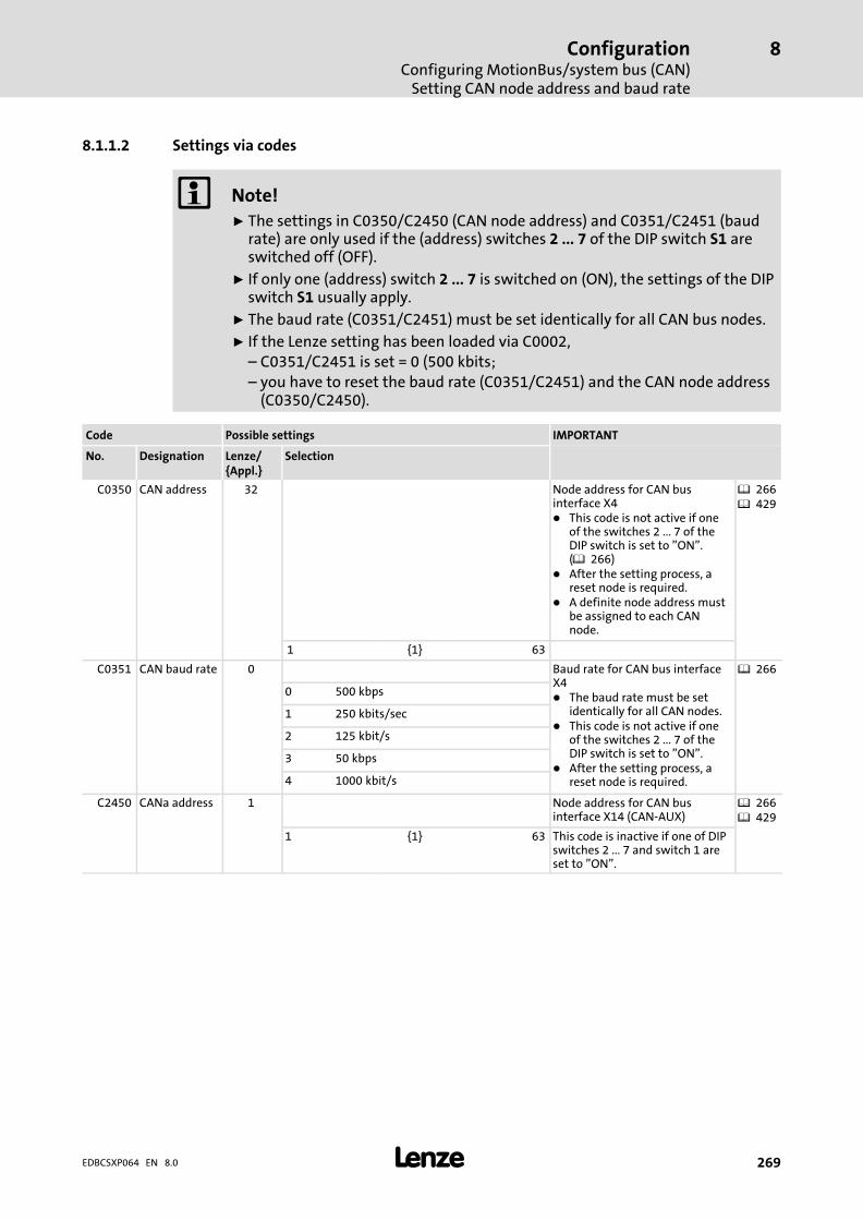
ConfigurationConfiguring MotionBus/system bus (CAN)
Setting CAN node address and baud rate
8
� 269EDBCSXP064 EN 8.0
8.1.1.2 Settings via codes
� Note!
ƒ The settings in C0350/C2450 (CAN node address) and C0351/C2451 (baudrate) are only used if the (address) switches 2 ... 7 of the DIP switch S1 areswitched off (OFF).
ƒ If only one (address) switch 2 ... 7 is switched on (ON), the settings of the DIPswitch S1 usually apply.
ƒ The baud rate (C0351/C2451) must be set identically for all CAN bus nodes.
ƒ If the Lenze setting has been loaded via C0002,– C0351/C2451 is set = 0 (500 kbits;– you have to reset the baud rate (C0351/C2451) and the CAN node address
(C0350/C2450).
Code Possible settings IMPORTANT
No. Designation Lenze/{Appl.}
Selection
C0350 CAN address 32 Node address for CAN businterface X4� This code is not active if one
of the switches 2 ... 7 of theDIP switch is set to "ON".(� 266)
� After the setting process, areset node is required.
� A definite node address mustbe assigned to each CANnode.
� 266� 429
1 {1} 63
C0351 CAN baud rate 0 Baud rate for CAN bus interfaceX4� The baud rate must be set
identically for all CAN nodes.� This code is not active if one
of the switches 2 ... 7 of theDIP switch is set to "ON".
� After the setting process, areset node is required.
� 266
0 500 kbps
1 250 kbits/sec
2 125 kbit/s
3 50 kbps
4 1000 kbit/s
C2450 CANa address 1 Node address for CAN businterface X14 (CAN−AUX)
� 266� 429
1 {1} 63 This code is inactive if one of DIPswitches 2 ... 7 and switch 1 areset to "ON".

ConfigurationConfiguring MotionBus/system bus (CAN)Setting CAN node address and baud rate
8
� 270 EDBCSXP064 EN 8.0
IMPORTANTPossible settingsCode
SelectionLenze/{Appl.}
DesignationNo.
C2451 CANa baudrate
0 Baud rate for CAN bus interfaceX14 (CAN−AUX)
� 266
0 500 kBit/s
1 250 kBit/s
2 125 kBit/s
3 50 kBit/s
4 1000 kBit/s
Save changes with C0003 = 1.
The settings are only accepted after carrying out one of the following actions:
ƒ Renewed switch−on of the 24 V low−voltage supply
ƒ Reset node via the bus system (by the network management (NMT))
ƒ Variable CAN_bResetNode_b or CANaux_bResetNode_b = TRUE
ƒ Reset node with C0358/2458 = 1
� Note!
If reset node is executed via GDC, communication will be interrupted. Youtherefore have to log in again manually or find the devices connected to thebus once again (fieldbus scan).
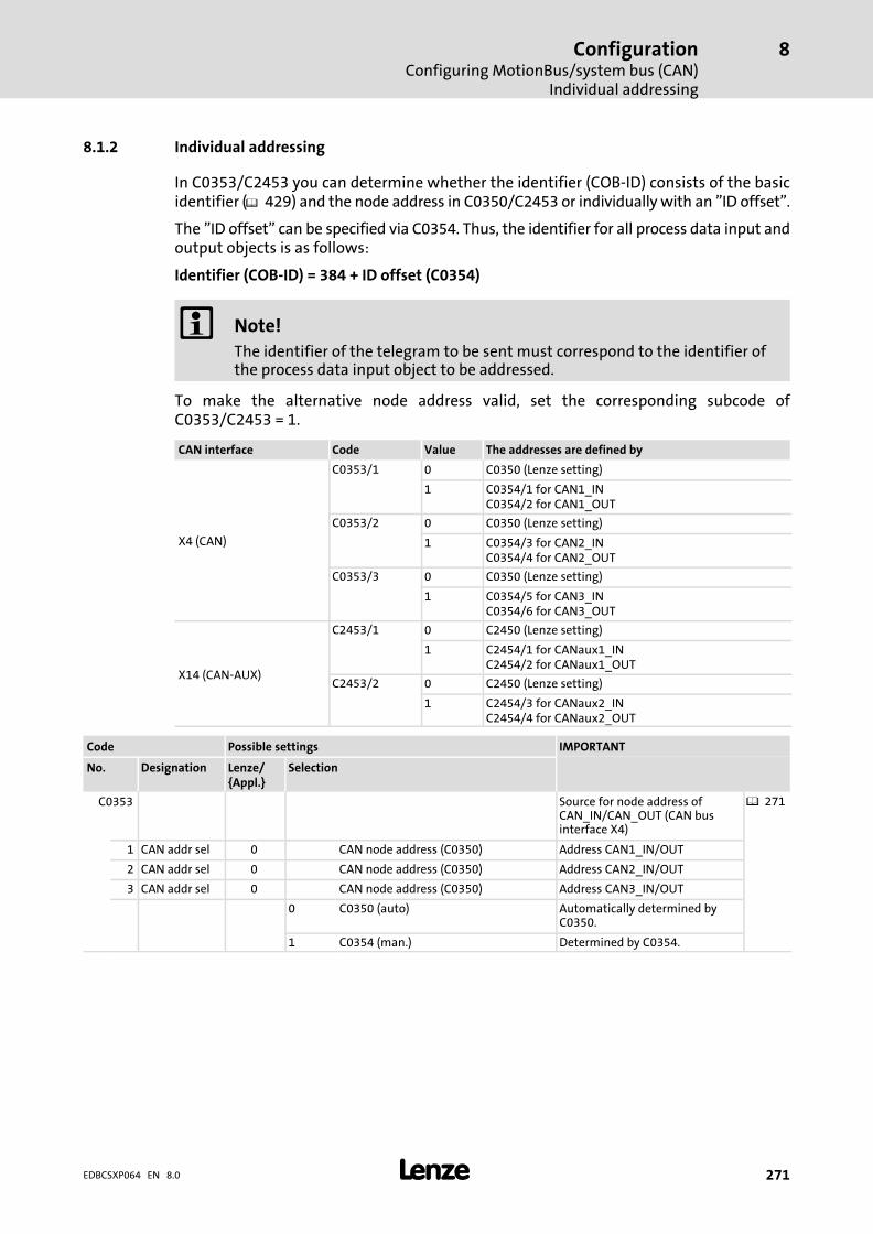
ConfigurationConfiguring MotionBus/system bus (CAN)
Individual addressing
8
� 271EDBCSXP064 EN 8.0
8.1.2 Individual addressing
In C0353/C2453 you can determine whether the identifier (COB−ID) consists of the basicidentifier (� 429) and the node address in C0350/C2453 or individually with an "ID offset".
The "ID offset" can be specified via C0354. Thus, the identifier for all process data input andoutput objects is as follows:
Identifier (COB−ID) = 384 + ID offset (C0354)
� Note!
The identifier of the telegram to be sent must correspond to the identifier ofthe process data input object to be addressed.
To make the alternative node address valid, set the corresponding subcode ofC0353/C2453 = 1.
CAN interface Code Value The addresses are defined by
X4 (CAN)
C0353/1 0 C0350 (Lenze setting)
1 C0354/1 for CAN1_INC0354/2 for CAN1_OUT
C0353/2 0 C0350 (Lenze setting)
1 C0354/3 for CAN2_INC0354/4 for CAN2_OUT
C0353/3 0 C0350 (Lenze setting)
1 C0354/5 for CAN3_INC0354/6 for CAN3_OUT
X14 (CAN−AUX)
C2453/1 0 C2450 (Lenze setting)
1 C2454/1 for CANaux1_INC2454/2 for CANaux1_OUT
C2453/2 0 C2450 (Lenze setting)
1 C2454/3 for CANaux2_INC2454/4 for CANaux2_OUT
Code Possible settings IMPORTANT
No. Designation Lenze/{Appl.}
Selection
C0353 Source for node address ofCAN_IN/CAN_OUT (CAN businterface X4)
� 271
1 CAN addr sel 0 CAN node address (C0350) Address CAN1_IN/OUT
2 CAN addr sel 0 CAN node address (C0350) Address CAN2_IN/OUT
3 CAN addr sel 0 CAN node address (C0350) Address CAN3_IN/OUT
0 C0350 (auto) Automatically determined byC0350.
1 C0354 (man.) Determined by C0354.

ConfigurationConfiguring MotionBus/system bus (CAN)Individual addressing
8
� 272 EDBCSXP064 EN 8.0
IMPORTANTPossible settingsCode
SelectionLenze/{Appl.}
DesignationNo.
C0354 Alternative node address forCAN_IN/CAN_OUT (CAN businterface X4)
� 271
1 CAN addr. 129 1 {1} 512 Address 2 CAN1_IN
2 CAN addr. 1 Address 2 CAN1_OUT
3 CAN addr. 257 Address 2 CAN2_IN
4 CAN addr. 258 Address 2 CAN2_OUT
5 CAN addr. 385 Address 2 CAN3_IN
6 CAN addr. 386 Address 2 CAN3_OUT
C2453 Source for system bus nodeaddresses ofCANaux_IN/CANaux_OUT (CANbus interface X14)
� 271
1 CANa addr sel 0 CAN node address (C2450) Address CANaux1_IN/OUT
2 CANa addr sel 0 CAN node address (C2450) Address CANaux2_IN/OUT
3 CANa addr sel 0 CAN node address (C2450) Address CANaux3_IN/OUT
0 C2450 (auto) Automatically determined byC2450
1 C2454 (man.) Determined by C2454
C2454 Alternative node addresses forCANaux_IN/CANaux_OUT (CANbus interface X14)
� 271
1 CANa addr. 129 1 {1} 512 CANaux1_INaddress 2
2 CANa addr. 1 CANaux1_OUTaddress 2
3 CANa addr. 257 CANaux2_INaddress 2
4 CANa addr. 258 CANaux2_OUTaddress 2
5 CANa addr. 385 CANaux3_IN address 2
6 CANa addr. 386 CANaux3_OUT address 2
Save changes with C0003 = 1.
The settings are only accepted after carrying out one of the following actions:
ƒ Renewed switch−on of the 24 V low−voltage supply
ƒ Reset node via the bus system (by the network management (NMT))
ƒ Variable CAN_bResetNode_b or CANaux_bResetNode_b = TRUE
ƒ Reset node with C0358/2458 = 1
� Note!
If reset node is executed via GDC, communication will be interrupted. Youtherefore have to log in again manually or find the devices connected to thebus once again (fieldbus scan).
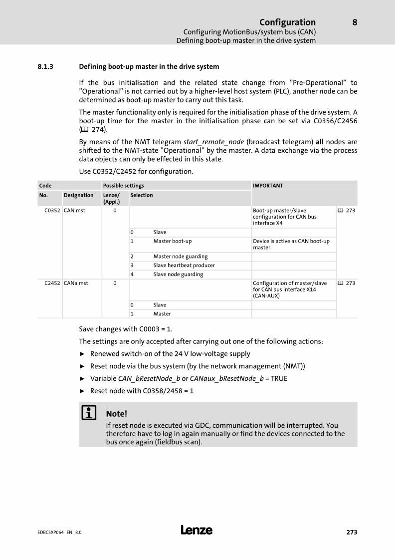
ConfigurationConfiguring MotionBus/system bus (CAN)
Defining boot−up master in the drive system
8
� 273EDBCSXP064 EN 8.0
8.1.3 Defining boot−up master in the drive system
If the bus initialisation and the related state change from "Pre−Operational" to"Operational" is not carried out by a higher−level host system (PLC), another node can bedetermined as boot−up master to carry out this task.
The master functionality only is required for the initialisation phase of the drive system. Aboot−up time for the master in the initialisation phase can be set via C0356/C2456( 274).
By means of the NMT telegram start_remote_node (broadcast telegram) all nodes areshifted to the NMT−state "Operational" by the master. A data exchange via the processdata objects can only be effected in this state.
Use C0352/C2452 for configuration.
Code Possible settings IMPORTANT
No. Designation Lenze/{Appl.}
Selection
C0352 CAN mst 0 Boot−up master/slaveconfiguration for CAN businterface X4
� 273
0 Slave
1 Master boot−up Device is active as CAN boot−upmaster.
2 Master node guarding
3 Slave heartbeat producer
4 Slave node guarding
C2452 CANa mst 0 Configuration of master/slavefor CAN bus interface X14(CAN−AUX)
� 273
0 Slave
1 Master
Save changes with C0003 = 1.
The settings are only accepted after carrying out one of the following actions:
ƒ Renewed switch−on of the 24 V low−voltage supply
ƒ Reset node via the bus system (by the network management (NMT))
ƒ Variable CAN_bResetNode_b or CANaux_bResetNode_b = TRUE
ƒ Reset node with C0358/2458 = 1
� Note!
If reset node is executed via GDC, communication will be interrupted. Youtherefore have to log in again manually or find the devices connected to thebus once again (fieldbus scan).
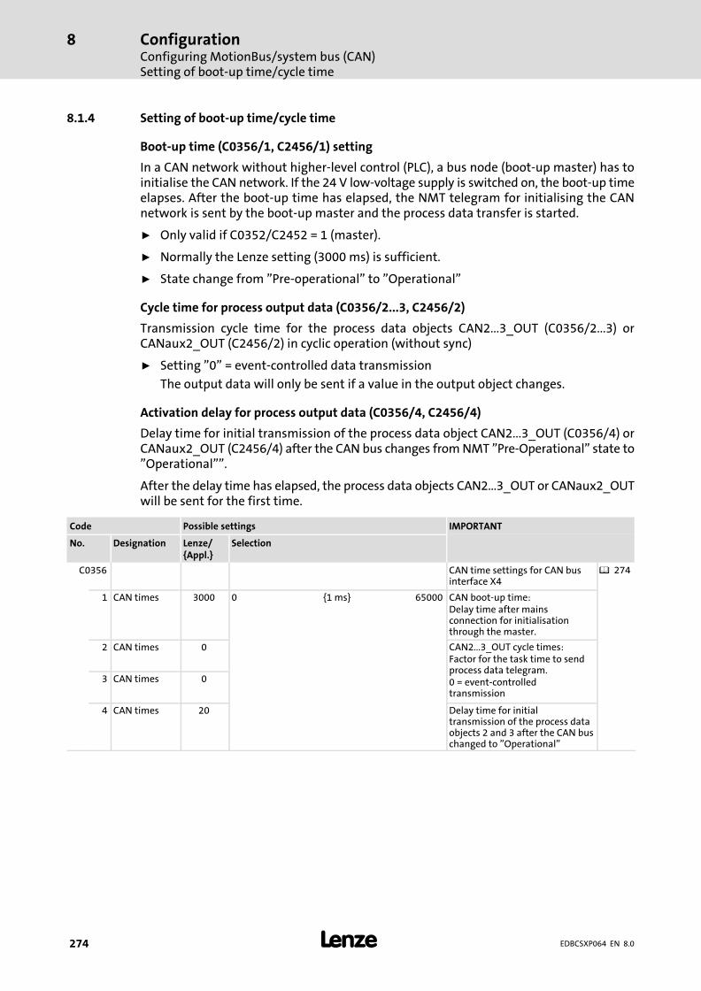
ConfigurationConfiguring MotionBus/system bus (CAN)Setting of boot−up time/cycle time
8
� 274 EDBCSXP064 EN 8.0
8.1.4 Setting of boot−up time/cycle time
Boot−up time (C0356/1, C2456/1) setting
In a CAN network without higher−level control (PLC), a bus node (boot−up master) has toinitialise the CAN network. If the 24 V low−voltage supply is switched on, the boot−up timeelapses. After the boot−up time has elapsed, the NMT telegram for initialising the CANnetwork is sent by the boot−up master and the process data transfer is started.
ƒ Only valid if C0352/C2452 = 1 (master).
ƒ Normally the Lenze setting (3000 ms) is sufficient.
ƒ State change from "Pre−operational" to "Operational"
Cycle time for process output data (C0356/2...3, C2456/2)
Transmission cycle time for the process data objects CAN2...3_OUT (C0356/2...3) orCANaux2_OUT (C2456/2) in cyclic operation (without sync)
ƒ Setting "0" = event−controlled data transmission
The output data will only be sent if a value in the output object changes.
Activation delay for process output data (C0356/4, C2456/4)
Delay time for initial transmission of the process data object CAN2...3_OUT (C0356/4) orCANaux2_OUT (C2456/4) after the CAN bus changes from NMT "Pre−Operational" state to"Operational"".
After the delay time has elapsed, the process data objects CAN2...3_OUT or CANaux2_OUTwill be sent for the first time.
Code Possible settings IMPORTANT
No. Designation Lenze/{Appl.}
Selection
C0356 CAN time settings for CAN businterface X4
� 274
1 CAN times 3000 0 {1 ms} 65000 CAN boot−up time:Delay time after mainsconnection for initialisationthrough the master.
2 CAN times 0 CAN2...3_OUT cycle times:Factor for the task time to sendprocess data telegram.0 = event−controlledtransmission
3 CAN times 0
4 CAN times 20 Delay time for initialtransmission of the process dataobjects 2 and 3 after the CAN buschanged to "Operational"
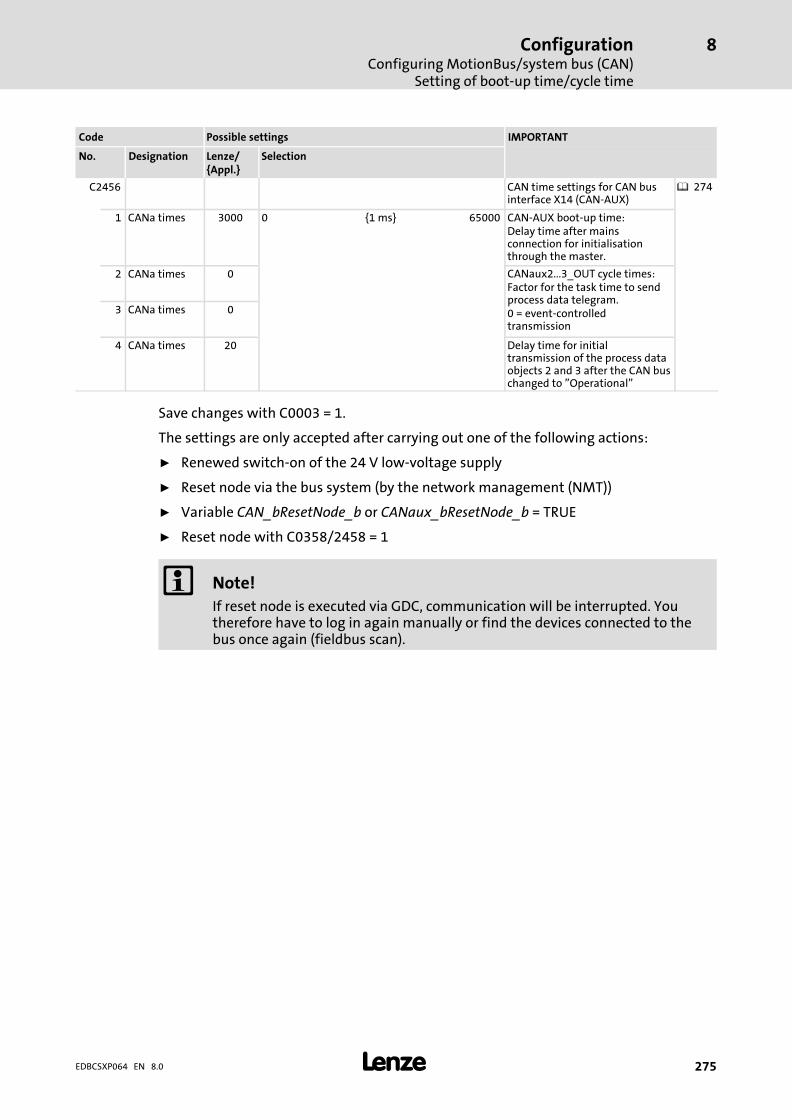
ConfigurationConfiguring MotionBus/system bus (CAN)
Setting of boot−up time/cycle time
8
� 275EDBCSXP064 EN 8.0
IMPORTANTPossible settingsCode
SelectionLenze/{Appl.}
DesignationNo.
C2456 CAN time settings for CAN businterface X14 (CAN−AUX)
� 274
1 CANa times 3000 0 {1 ms} 65000 CAN−AUX boot−up time:Delay time after mainsconnection for initialisationthrough the master.
2 CANa times 0 CANaux2...3_OUT cycle times:Factor for the task time to sendprocess data telegram.0 = event−controlledtransmission
3 CANa times 0
4 CANa times 20 Delay time for initialtransmission of the process dataobjects 2 and 3 after the CAN buschanged to "Operational"
Save changes with C0003 = 1.
The settings are only accepted after carrying out one of the following actions:
ƒ Renewed switch−on of the 24 V low−voltage supply
ƒ Reset node via the bus system (by the network management (NMT))
ƒ Variable CAN_bResetNode_b or CANaux_bResetNode_b = TRUE
ƒ Reset node with C0358/2458 = 1
� Note!
If reset node is executed via GDC, communication will be interrupted. Youtherefore have to log in again manually or find the devices connected to thebus once again (fieldbus scan).
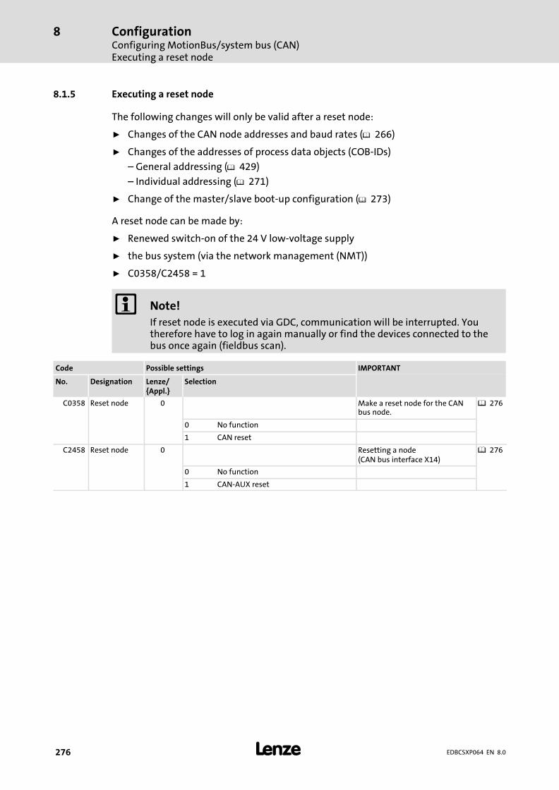
ConfigurationConfiguring MotionBus/system bus (CAN)Executing a reset node
8
� 276 EDBCSXP064 EN 8.0
8.1.5 Executing a reset node
The following changes will only be valid after a reset node:
ƒ Changes of the CAN node addresses and baud rates (� 266)
ƒ Changes of the addresses of process data objects (COB−IDs)
– General addressing (� 429)
– Individual addressing (� 271)
ƒ Change of the master/slave boot−up configuration (� 273)
A reset node can be made by:
ƒ Renewed switch−on of the 24 V low−voltage supply
ƒ the bus system (via the network management (NMT))
ƒ C0358/C2458 = 1
� Note!
If reset node is executed via GDC, communication will be interrupted. Youtherefore have to log in again manually or find the devices connected to thebus once again (fieldbus scan).
Code Possible settings IMPORTANT
No. Designation Lenze/{Appl.}
Selection
C0358 Reset node 0 Make a reset node for the CANbus node.
� 276
0 No function
1 CAN reset
C2458 Reset node 0 Resetting a node(CAN bus interface X14)
� 276
0 No function
1 CAN−AUX reset

ConfigurationConfiguring MotionBus/system bus (CAN)
Guiding angle selection and synchronisation via MotionBus (CAN)
8
� 277EDBCSXP064 EN 8.0
8.1.6 Guiding angle selection and synchronisation via MotionBus (CAN)
� Note!
ƒ This function is activated by C3095/x = 31 (electrical shaft ("E−shaft") viaMotionBus (CAN)) in the positioning profile.
ƒ An external control master is required for selecting the setpoint telegrams!
Please observe the following sequence during commissioning:
Device Step Description
All devices 1. Commission the controller andMotionBus (CAN).
2. Inhibit controller.� Press the <F9> key in GDC.
� 241
Slave drives 3. C1120 = 1 Active synchronisation by sync telegram viasystem bus.
4. C0366 = 1 Sync response:Slaves respond to sync telegram.
Master(ext. control)
5. Define the telegram sequence (identifier):A Send setpoint telegram to all slaves.B Transmit sync telegram.C Receive response of all slaves.
� For the structure of the setpoint telegram,see � 158.
� The angle is selected with the bytes 5 − 8("PosDirect") of the setpoint telegram inincrements (210 inc = 1 revolution of themotor shaft).
6. Start communication, send sync telegrams.
Slave drives 7. Read C0362 from the master. Retrieve cycle time of the sync telegram fromthe master.
8. Set C1121 according to C0362 of the master. Adjust the time distance of the synctelegrams to be received to the cycle time ofthe master.
9. Set C1123. Set optimum size of the "sync window".� If the sync signal "jitters" heavily (� 278),
increase "time slot".� Guide values subject to the CAN baud
rate:– 1 Mbit � 0.2 ms– 500 kbit � 0.4 ms– 250 kbit � 0.8 ms
10. Enable the controller via the signal"CANSync−InsideWindow" applied to thedigital output.
Synchronisation monitoring:� If "CANSync−InsideWindow" = TRUE,
enable the controller.
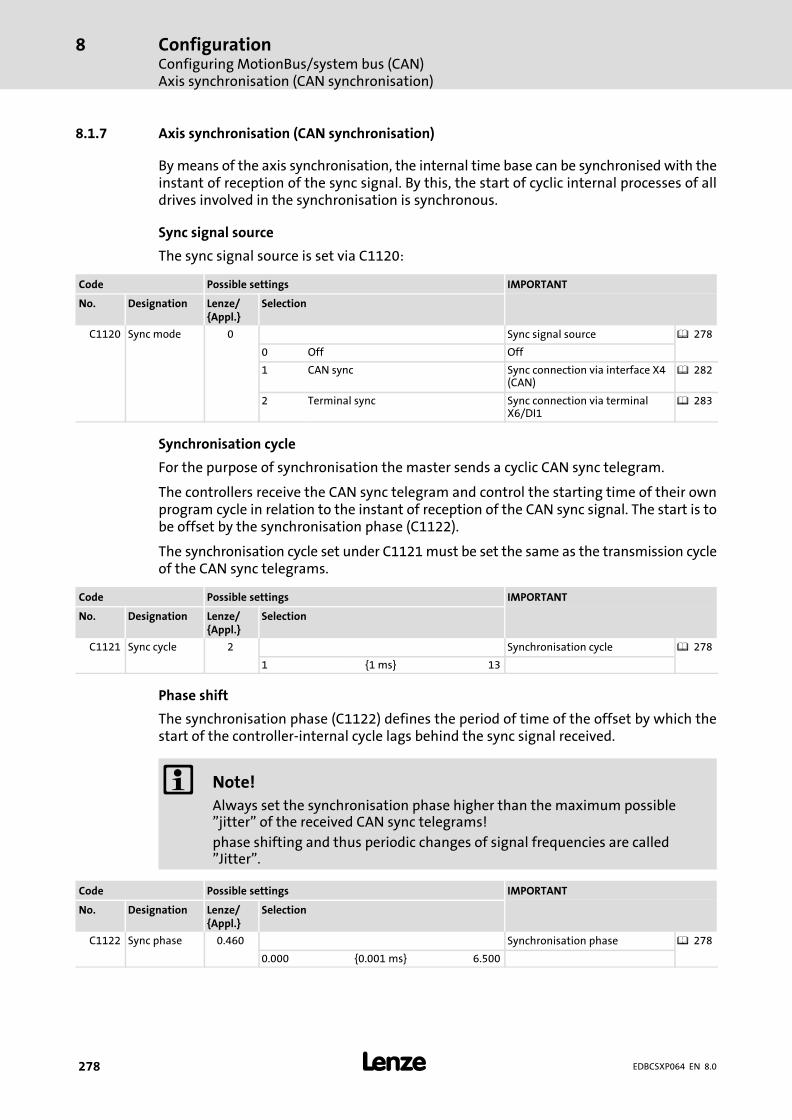
ConfigurationConfiguring MotionBus/system bus (CAN)Axis synchronisation (CAN synchronisation)
8
� 278 EDBCSXP064 EN 8.0
8.1.7 Axis synchronisation (CAN synchronisation)
By means of the axis synchronisation, the internal time base can be synchronised with theinstant of reception of the sync signal. By this, the start of cyclic internal processes of alldrives involved in the synchronisation is synchronous.
Sync signal source
The sync signal source is set via C1120:
Code Possible settings IMPORTANT
No. Designation Lenze/{Appl.}
Selection
C1120 Sync mode 0 Sync signal source � 278
0 Off Off
1 CAN sync Sync connection via interface X4(CAN)
� 282
2 Terminal sync Sync connection via terminalX6/DI1
� 283
Synchronisation cycle
For the purpose of synchronisation the master sends a cyclic CAN sync telegram.
The controllers receive the CAN sync telegram and control the starting time of their ownprogram cycle in relation to the instant of reception of the CAN sync signal. The start is tobe offset by the synchronisation phase (C1122).
The synchronisation cycle set under C1121 must be set the same as the transmission cycleof the CAN sync telegrams.
Code Possible settings IMPORTANT
No. Designation Lenze/{Appl.}
Selection
C1121 Sync cycle 2 Synchronisation cycle � 278
1 {1 ms} 13
Phase shift
The synchronisation phase (C1122) defines the period of time of the offset by which thestart of the controller−internal cycle lags behind the sync signal received.
� Note!
Always set the synchronisation phase higher than the maximum possible"jitter" of the received CAN sync telegrams!
phase shifting and thus periodic changes of signal frequencies are called"Jitter".
Code Possible settings IMPORTANT
No. Designation Lenze/{Appl.}
Selection
C1122 Sync phase 0.460 Synchronisation phase � 278
0.000 {0.001 ms} 6.500
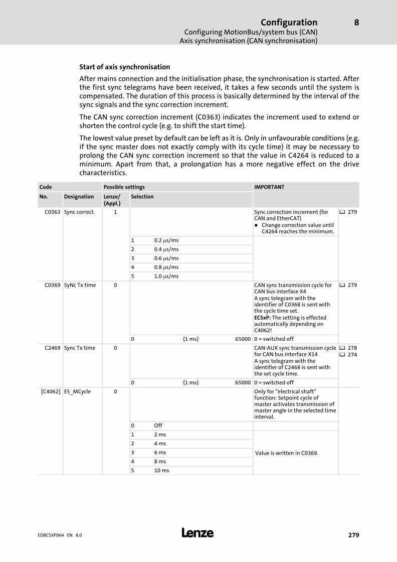
ConfigurationConfiguring MotionBus/system bus (CAN)
Axis synchronisation (CAN synchronisation)
8
� 279EDBCSXP064 EN 8.0
Start of axis synchronisation
After mains connection and the initialisation phase, the synchronisation is started. Afterthe first sync telegrams have been received, it takes a few seconds until the system iscompensated. The duration of this process is basically determined by the interval of thesync signals and the sync correction increment.
The CAN sync correction increment (C0363) indicates the increment used to extend orshorten the control cycle (e.g. to shift the start time).
The lowest value preset by default can be left as it is. Only in unfavourable conditions (e.g.if the sync master does not exactly comply with its cycle time) it may be necessary toprolong the CAN sync correction increment so that the value in C4264 is reduced to aminimum. Apart from that, a prolongation has a more negative effect on the drivecharacteristics.
Code Possible settings IMPORTANT
No. Designation Lenze/{Appl.}
Selection
C0363 Sync correct. 1 Sync correction increment (forCAN and EtherCAT)� Change correction value until
C4264 reaches the minimum.
� 279
1 0.2 �s/ms
2 0.4 �s/ms
3 0.6 �s/ms
4 0.8 �s/ms
5 1.0 �s/ms
C0369 SyNc Tx time 0 CAN sync transmission cycle forCAN bus interface X4A sync telegram with theidentifier of C0368 is sent withthe cycle time set.ECSxP: The setting is effectedautomatically depending onC4062!
� 279
0 {1 ms} 65000 0 = switched off
C2469 Sync Tx time 0 CAN−AUX sync transmission cyclefor CAN bus interface X14A sync telegram with theidentifier of C2468 is sent withthe set cycle time.
� 278� 274
0 {1 ms} 65000 0 = switched off
[C4062] ES_MCycle 0 Only for "electrical shaft"function: Setpoint cycle ofmaster activates transmission ofmaster angle in the selected timeinterval.
0 Off
1 2 ms
Value is written in C0369.
2 4 ms
3 6 ms
4 8 ms
5 10 ms
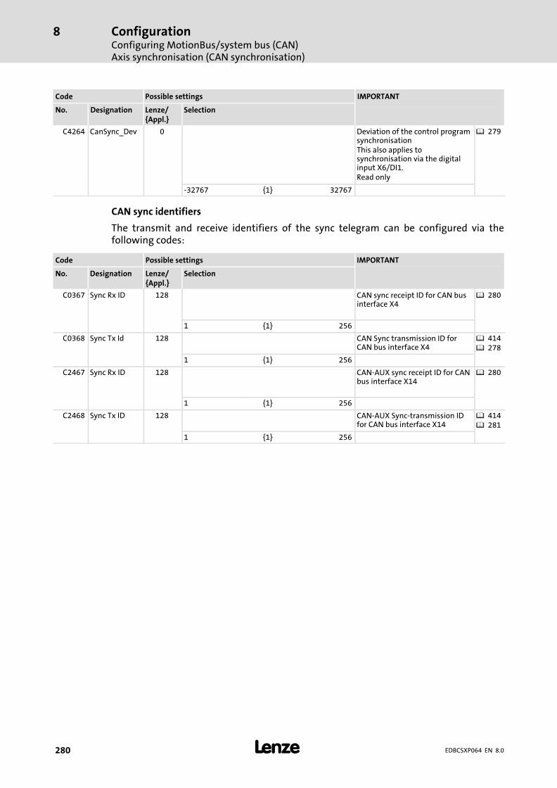
ConfigurationConfiguring MotionBus/system bus (CAN)Axis synchronisation (CAN synchronisation)
8
� 280 EDBCSXP064 EN 8.0
IMPORTANTPossible settingsCode
SelectionLenze/{Appl.}
DesignationNo.
C4264 CanSync_Dev 0 Deviation of the control programsynchronisationThis also applies tosynchronisation via the digitalinput X6/DI1.Read only
� 279
−32767 {1} 32767
CAN sync identifiers
The transmit and receive identifiers of the sync telegram can be configured via thefollowing codes:
Code Possible settings IMPORTANT
No. Designation Lenze/{Appl.}
Selection
C0367 Sync Rx ID 128 CAN sync receipt ID for CAN businterface X4
� 280
1 {1} 256
C0368 Sync Tx Id 128 CAN Sync transmission ID forCAN bus interface X4
� 414� 278
1 {1} 256
C2467 Sync Rx ID 128 CAN−AUX sync receipt ID for CANbus interface X14
� 280
1 {1} 256
C2468 Sync Tx ID 128 CAN−AUX Sync−transmission IDfor CAN bus interface X14
� 414� 281
1 {1} 256
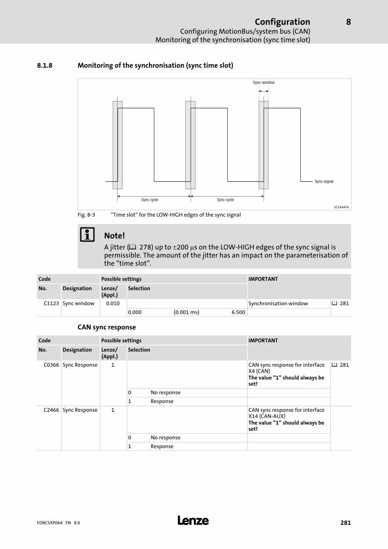
ConfigurationConfiguring MotionBus/system bus (CAN)
Monitoring of the synchronisation (sync time slot)
8
� 281EDBCSXP064 EN 8.0
8.1.8 Monitoring of the synchronisation (sync time slot)
Sync-window
Sync cycleSync cycle
Sync-signal
ECSXA474
Fig. 8−3 "Time slot" for the LOW−HIGH edges of the sync signal
� Note!
A jitter ( 278) up to �200 �s on the LOW−HIGH edges of the sync signal ispermissible. The amount of the jitter has an impact on the parameterisation ofthe "time slot".
Code Possible settings IMPORTANT
No. Designation Lenze/{Appl.}
Selection
C1123 Sync window 0.010 Synchronisation window � 281
0.000 {0.001 ms} 6.500
CAN sync response
Code Possible settings IMPORTANT
No. Designation Lenze/{Appl.}
Selection
C0366 Sync Response 1 CAN sync response for interfaceX4 (CAN)The value "1" should always beset!
� 281
0 No response
1 Response
C2466 Sync Response 1 CAN sync response for interfaceX14 (CAN−AUX)The value "1" should always beset!
0 No response
1 Response

ConfigurationConfiguring MotionBus/system bus (CAN)Axis synchronisation via CAN
8
� 282 EDBCSXP064 EN 8.0
8.1.9 Axis synchronisation via CAN
The CAN interface X4 serves to transfer the CAN sync telegram as synchronisation signaland the process data.
Please observe the following sequence during commissioning:
Device Step Description
All devices 1. Commission the controller and the CAN bus.
2. Inhibit the drive controllers.� Press the <F9> key in GDC.
� 241
Slaves 3. Connect "CANSync−InsideWindow" withdigital output.
4. C1120 = 1 Active synchronisation by sync telegram viaCAN bus.
5. C0366 = 1 (Lenze setting) CAN sync reaction:� Slaves respond to sync telegram.
Master 6. Define the telegram (identifier) sequence:A . Send new setpoint to all slaves.B Send sync telegram.C Receive response of all slaves.
7. Start communication/send sync telegrams.
Slaves 8. Read C0362 from the master. Retrieve cycle time of the sync telegram fromthe master.
9. Set C1121 according to C0362 of the master. Adjust the time distance of the synctelegrams to be received to the cycle time ofthe master.
10. Set C1123. Set optimum size for the "time slot".� If the sync signal "jitters" heavily (� 278),
increase "time slot".
Slaves 11. Enable the controller via the signal"CANSync−InsideWindow" applied to thedigital output.
Synchronisation monitoring:� If "CANSync−InsideWindow" = TRUE,
enable the controller.

ConfigurationConfiguring MotionBus/system bus (CAN)
Axis synchronisation via terminal X6/DI1
8
� 283EDBCSXP064 EN 8.0
8.1.10 Axis synchronisation via terminal X6/DI1
The transmission paths for the sync signal and the process data are separated.
ƒ The process data are transmitted via the CAN interface X4.
ƒ The sync signal is injected via the digital input X6/DI1.
Please observe the following sequence during commissioning:
Device Step Description
All devices 1. Commission the controller and the CAN bus.
2. Inhibit the drive controllers.� Press the <F9> key in GDC.
� 241
Slaves 3. Connect "CANSync−InsideWindow" withdigital output.
4. Connect the sync signal of the master toterminal X6/DI1.
Slaves 5. C1120 = 2 Synchronisation through sync signal viaterminal X6/DI1 (DigIn_bIn1_b) is active.
Slaves 6. C0366 = 1 (Lenze setting) CAN sync reaction:� Slaves respond to sync telegram.
Master 7. Start communication/send sync signals.
Slaves 8. Read C0362 from the master. Retrieve cycle time of the sync signal fromthe master.
9. Set C1121 according to C0362 of the master. Adjust the time distance of the sync signal tobe received to the cycle time of the master.
10. Set C1123. Set optimum size for the "time slot".� If the sync signal "jitters" heavily (� 278),
increase "time slot".
11. Enable the controller via the signal"CANSync−InsideWindow" applied to thedigital output.
Synchronisation monitoring:� If "CANSync−InsideWindow" = TRUE,
enable the controller.
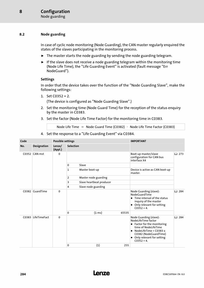
ConfigurationNode guarding
8
� 284 EDBCSXP064 EN 8.0
8.2 Node guarding
In case of cyclic node monitoring (Node Guarding), the CAN master regularly enquired thestates of the slaves participating in the monitoring process.
ƒ The master starts the node guarding by sending the node guarding telegram.
ƒ If the slave does not receive a node guarding telegram within the monitoring time(Node Life Time), the "Life Guarding Event" is activated (fault message "ErrNodeGuard").
Settings
In order that the device takes over the function of the "Node Guarding Slave", make thefollowing settings:
1. Set C0352 = 2.
(The device is configured as "Node Guarding Slave".)
2. Set the monitoring time (Node Guard Time) for the reception of the status enquiryby the master in C0383.
3. Set the factor (Node Life Time Factor) for the monitoring time in C0383.
Node�Life�Time� �� Node�Guard�Time�(C0382)� �� Node�Life�Time�Factor�(C0383)
4. Set the response to a "Life Guarding Event" via C0384.
Code Possible settings IMPORTANT
No. Designation Lenze/{Appl.}
Selection
C0352 CAN mst 0 Boot−up master/slaveconfiguration for CAN businterface X4
� 273
0 Slave
1 Master boot−up Device is active as CAN boot−upmaster.
2 Master node guarding
3 Slave heartbeat producer
4 Slave node guarding
C0382 GuardTime 0 Node Guarding (slave):NodeGuardTime� Time interval of the status
inquiry of the master� Only relevant for setting
C0352 = 4.
� 284
0 {1 ms} 65535
C0383 LifeTimeFact 0 Node Guarding (slave):NodeLifeTime factor� Factor for the monitoring
time of NodeLifeTime� NodeLifeTime = C0383 x
C0382 (NodeGuardTime)� Only relevant for setting
C0352 = 4.
� 284
0 {1} 255
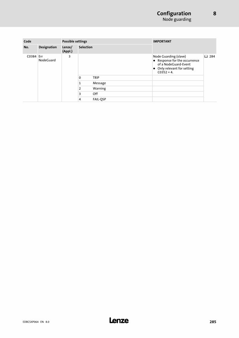
ConfigurationNode guarding
8
� 285EDBCSXP064 EN 8.0
IMPORTANTPossible settingsCode
SelectionLenze/{Appl.}
DesignationNo.
C0384 ErrNodeGuard
3 Node Guarding (slave)� Response for the occurrence
of a NodeGuard−Event� Only relevant for setting
C0352 = 4.
� 284
0 TRIP
1 Message
2 Warning
3 Off
4 FAIL−QSP
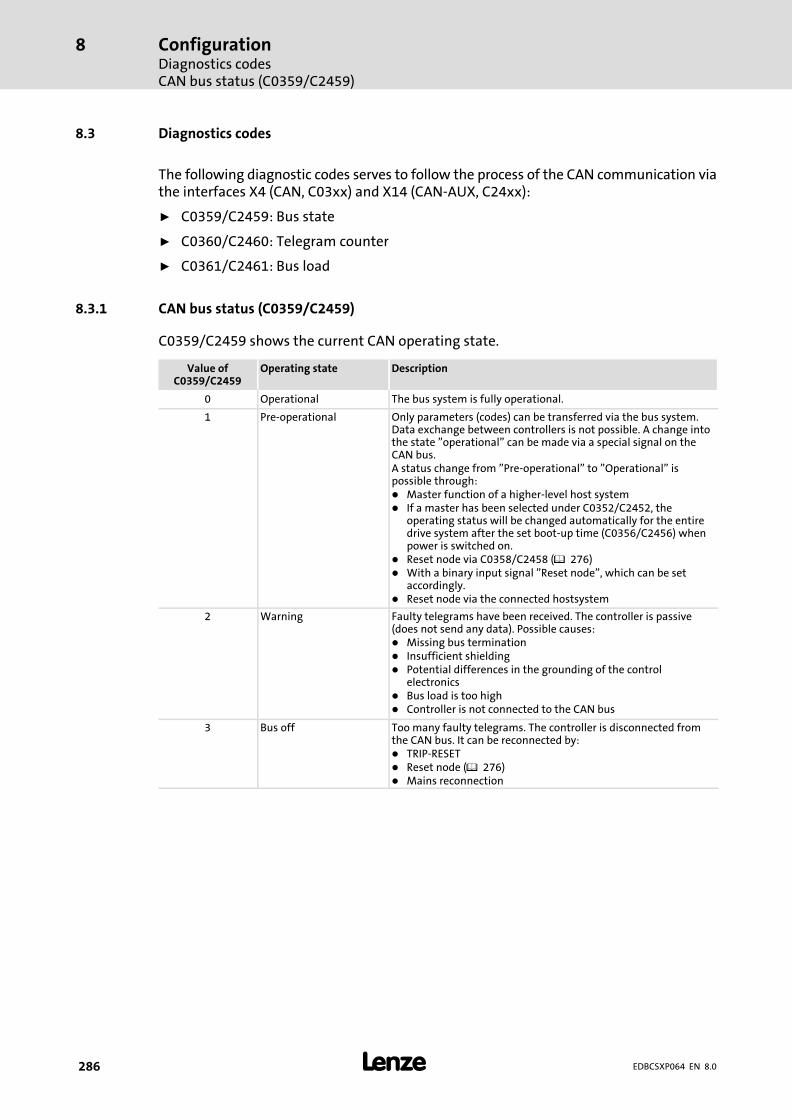
ConfigurationDiagnostics codesCAN bus status (C0359/C2459)
8
� 286 EDBCSXP064 EN 8.0
8.3 Diagnostics codes
The following diagnostic codes serves to follow the process of the CAN communication viathe interfaces X4 (CAN, C03xx) and X14 (CAN−AUX, C24xx):
ƒ C0359/C2459: Bus state
ƒ C0360/C2460: Telegram counter
ƒ C0361/C2461: Bus load
8.3.1 CAN bus status (C0359/C2459)
C0359/C2459 shows the current CAN operating state.
Value ofC0359/C2459
Operating state Description
0 Operational The bus system is fully operational.
1 Pre−operational Only parameters (codes) can be transferred via the bus system.Data exchange between controllers is not possible. A change intothe state "operational" can be made via a special signal on theCAN bus.A status change from "Pre−operational" to "Operational" ispossible through:� Master function of a higher−level host system� If a master has been selected under C0352/C2452, the
operating status will be changed automatically for the entiredrive system after the set boot−up time (C0356/C2456) whenpower is switched on.
� Reset node via C0358/C2458 (� 276)� With a binary input signal "Reset node", which can be set
accordingly.� Reset node via the connected hostsystem
2 Warning Faulty telegrams have been received. The controller is passive(does not send any data). Possible causes:� Missing bus termination� Insufficient shielding� Potential differences in the grounding of the control
electronics� Bus load is too high� Controller is not connected to the CAN bus
3 Bus off Too many faulty telegrams. The controller is disconnected fromthe CAN bus. It can be reconnected by:� TRIP−RESET� Reset node (� 276)� Mains reconnection

ConfigurationDiagnostics codes
CAN telegram counter (C0360/2460)
8
� 287EDBCSXP064 EN 8.0
8.3.2 CAN telegram counter (C0360/2460)
C0360/2460 counts for all parameter data channel the telegrams which are valid for thecontroller. The counters have a width of 16 bits. If the value "65535" is exceeded, countingrestarts with "0".
Counted messages:
C0360/C2460 Meaning
Subcode 1 All sent telegrams
Subcode 2 All received telegrams
Subcode 3 Telegrams sent of CAN1_OUT/CANaux1_OUT
Subcode 4 Telegrams sent of CAN2_OUT/CANaux2_OUT� Always "0"; channel is not used!
Subcode 5 Telegrams sent of CAN3_OUT/CANaux3_OUT� Always "0"; channel is not used!
Subcode 6 Telegrams sent of parameter data channel 1
Subcode 7 Telegrams sent of parameter data channel 2
Subcode 8 Telegrams received of CAN1_IN/CANaux1_IN
Subcode 9 Telegrams received of CAN2_IN/CANaux2_IN� Always "0"; channel is not used!
Subcode 10 Telegrams received of CAN3_IN/CANaux3_IN� Always "0"; channel is not used!
Subcode 11 Telegrams received of parameter data channel 1
Subcode 12 Telegrams received of parameter data channel 2

ConfigurationDiagnostics codesCAN bus load (C0361/2461)
8
� 288 EDBCSXP064 EN 8.0
8.3.3 CAN bus load (C0361/2461)
Use C0361/C2461 to determine the bus load through the controller or the individual datachannels in percent. Faulty telegrams are not considered.
Bus load of the individual subcodes:
C0361/C2461 Meaning
Subcode 1 All telegrams sent
Subcode 2 All telegrams received
Subcode 3 Telegrams sent of CAN1_OUT/CANaux1_OUT
Subcode 4 Telegrams sent of CAN2_OUT/CANaux2_OUT� Always "0"; channel is not used!
Subcode 5 Telegrams sent of CAN3_OUT/CANaux3_OUT� Always "0"; channel is not used!
Subcode 6 Telegrams sent from parameter data channel 1
Subcode 7 Telegrams sent of parameter data channel 2
Subcode 8 Telegrams received of CAN1_IN/CANaux1_OUT
Subcode 9 Telegrams received of CAN2_IN/CANaux2_OUT� Always "0"; channel is not used!
Subcode 10 Telegrams received of CAN3_IN/CANaux3_OUT� Always "0"; channel is not used!
Subcode 11 Telegrams received from parameter data channel 1
Subcode 12 Telegrams received of parameter data channel 2
The data transfer is limited. The limits are determined by the number of telegramstransmitted per time unit and the baud rate.
The limits can be determined during data exchange in a drive network by adding all drivesinvolved under C0361/1 or C2461/1.
Example:
Drives/host system (PLC) Bus load
C0361/1 − controller 1 23.5 %
C0361/1 − controller 2 12.6 %
Host system (PLC) 16,0 %
52.1 % (total)
Two drives and the host system (PLC) are interconnected via the CAN bus.
� Note!
ƒ Max. bus load of all devices involved: 80 %
ƒ If other devices are connected, as for instance decentralised inputs andoutputs, their telegrams must be taken into consideration.
ƒ If the time between the individual sync telegrams is too short the bus can beoverloaded.– Remedy: Change the synchronisation cycle of the host system (PLC) and
the controller (C1121).
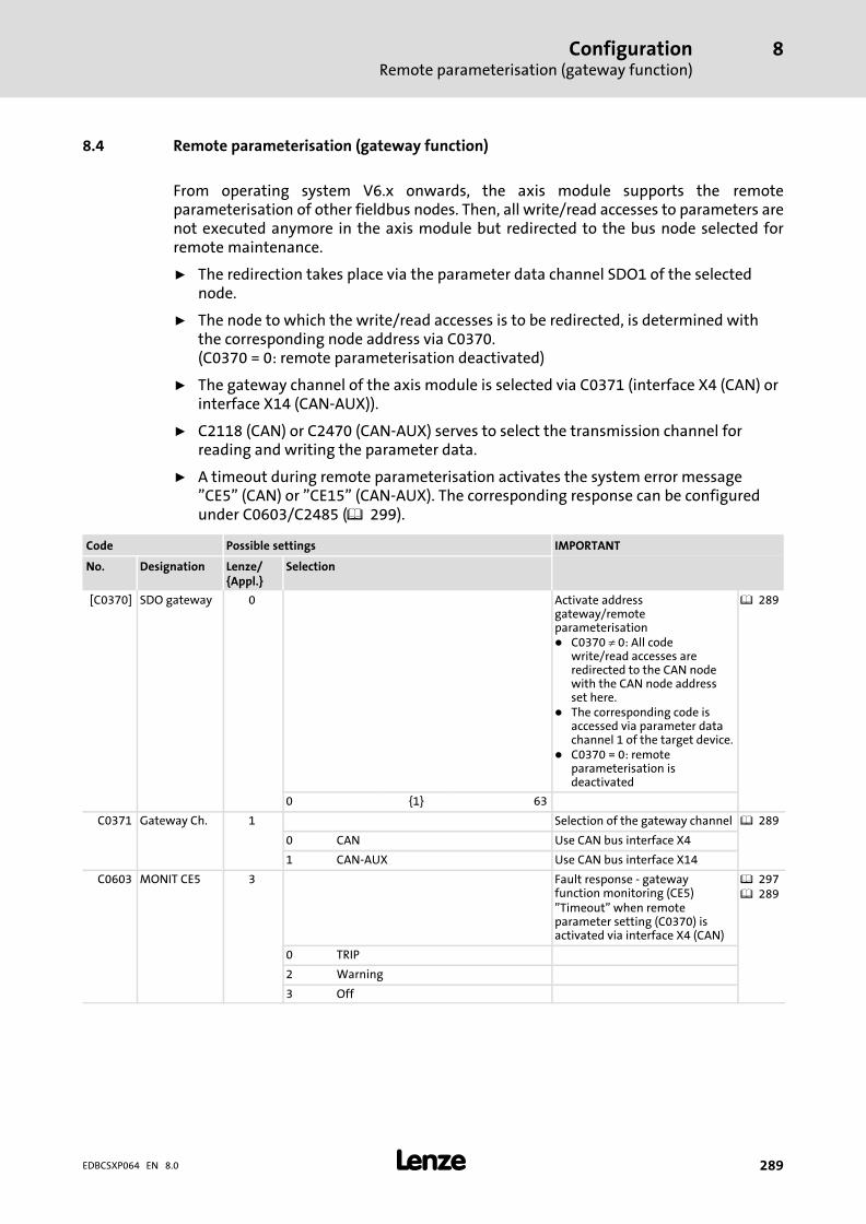
ConfigurationRemote parameterisation (gateway function)
8
� 289EDBCSXP064 EN 8.0
8.4 Remote parameterisation (gateway function)
From operating system V6.x onwards, the axis module supports the remoteparameterisation of other fieldbus nodes. Then, all write/read accesses to parameters arenot executed anymore in the axis module but redirected to the bus node selected forremote maintenance.
ƒ The redirection takes place via the parameter data channel SDO1 of the selectednode.
ƒ The node to which the write/read accesses is to be redirected, is determined withthe corresponding node address via C0370.(C0370 = 0: remote parameterisation deactivated)
ƒ The gateway channel of the axis module is selected via C0371 (interface X4 (CAN) orinterface X14 (CAN−AUX)).
ƒ C2118 (CAN) or C2470 (CAN−AUX) serves to select the transmission channel forreading and writing the parameter data.
ƒ A timeout during remote parameterisation activates the system error message"CE5" (CAN) or "CE15" (CAN−AUX). The corresponding response can be configuredunder C0603/C2485 ( 299).
Code Possible settings IMPORTANT
No. Designation Lenze/{Appl.}
Selection
[C0370] SDO gateway 0 Activate addressgateway/remoteparameterisation� C0370 � 0: All code
write/read accesses areredirected to the CAN nodewith the CAN node addressset here.
� The corresponding code isaccessed via parameter datachannel 1 of the target device.
� C0370 = 0: remoteparameterisation isdeactivated
� 289
0 {1} 63
C0371 Gateway Ch. 1 Selection of the gateway channel � 289
0 CAN Use CAN bus interface X4
1 CAN−AUX Use CAN bus interface X14
C0603 MONIT CE5 3 Fault response − gatewayfunction monitoring (CE5)"Timeout" when remoteparameter setting (C0370) isactivated via interface X4 (CAN)
� 297� 289
0 TRIP
2 Warning
3 Off
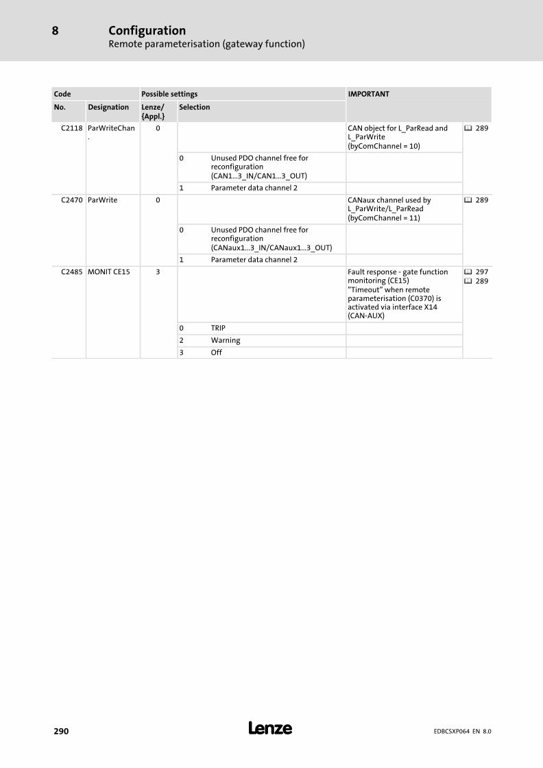
ConfigurationRemote parameterisation (gateway function)
8
� 290 EDBCSXP064 EN 8.0
IMPORTANTPossible settingsCode
SelectionLenze/{Appl.}
DesignationNo.
C2118 ParWriteChan.
0 CAN object for L_ParRead andL_ParWrite(byComChannel = 10)
� 289
0 Unused PDO channel free forreconfiguration(CAN1...3_IN/CAN1...3_OUT)
1 Parameter data channel 2
C2470 ParWrite 0 CANaux channel used byL_ParWrite/L_ParRead(byComChannel = 11)
� 289
0 Unused PDO channel free forreconfiguration(CANaux1...3_IN/CANaux1...3_OUT)
1 Parameter data channel 2
C2485 MONIT CE15 3 Fault response − gate functionmonitoring (CE15)"Timeout" when remoteparameterisation (C0370) isactivated via interface X14(CAN−AUX)
� 297� 289
0 TRIP
2 Warning
3 Off

Monitoring functions 9
� 291EDBCSXP064 EN 8.0
9 Monitoring functions
Different monitoring functions ( 293) protect the drive system from impermissibleoperating conditions.
If a monitoring function responds,
ƒ the set fault response is triggered to protect the drive and
ƒ the fault message is entered position 1 in the fault history buffer (C0168/x, in caseof ECSxP: C4168/x) ( 338).
In the fault history buffer (C0168/x), fault messages are saved in codes as 4−digit numbers.The first digit describes the type of fault response. The last three digits correspond to thefault number.
No. of the fault message Type of response
0xxx TRIP
1xxx Message
2xxx Warning
3xxx FAIL−QSP (only for ECSxS/P/M/A axis modules)
Example: C0168/1 = 2061
ƒ x061:
The current fault (subcode 1 of C0168) is a communication error (fault message"CE0"/no. "x061") between the AIF module and the ECS axis module.
ƒ 2xxx:
The fault response is a warning.
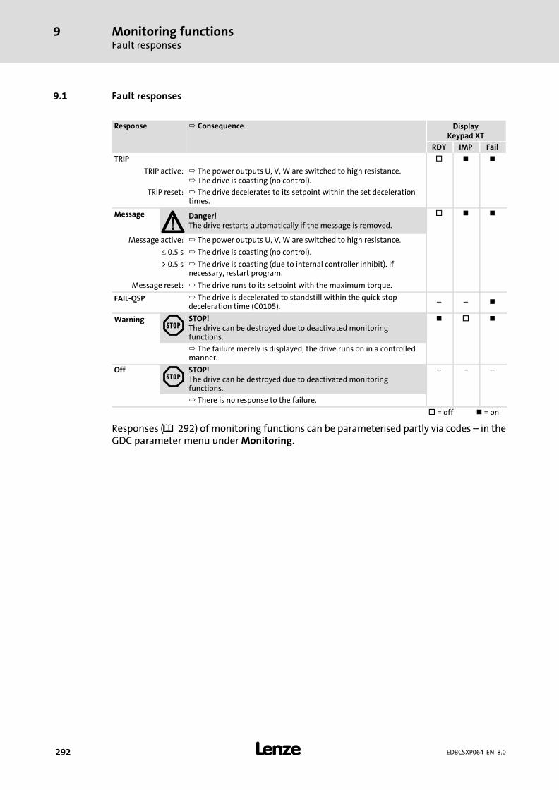
Monitoring functionsFault responses
9
� 292 EDBCSXP064 EN 8.0
9.1 Fault responses
Response Consequence DisplayKeypad XT
RDY IMP Fail
TRIP �
TRIP active: The power outputs U, V, W are switched to high resistance. The drive is coasting (no control).
TRIP reset: The drive decelerates to its setpoint within the set decelerationtimes.
Message Danger!The drive restarts automatically if the message is removed.
�
Message active: The power outputs U, V, W are switched to high resistance.
� 0.5 s The drive is coasting (no control).
> 0.5 s The drive is coasting (due to internal controller inhibit). Ifnecessary, restart program.
Message reset: The drive runs to its setpoint with the maximum torque.
FAIL−QSP The drive is decelerated to standstill within the quick stopdeceleration time (C0105).
˘ ˘
Warning STOP!The drive can be destroyed due to deactivated monitoringfunctions.
�
The failure merely is displayed, the drive runs on in a controlledmanner.
Off STOP!The drive can be destroyed due to deactivated monitoringfunctions.
˘ ˘ ˘
There is no response to the failure.
� = off = on
Responses ( 292) of monitoring functions can be parameterised partly via codes ˘ in theGDC parameter menu under Monitoring.
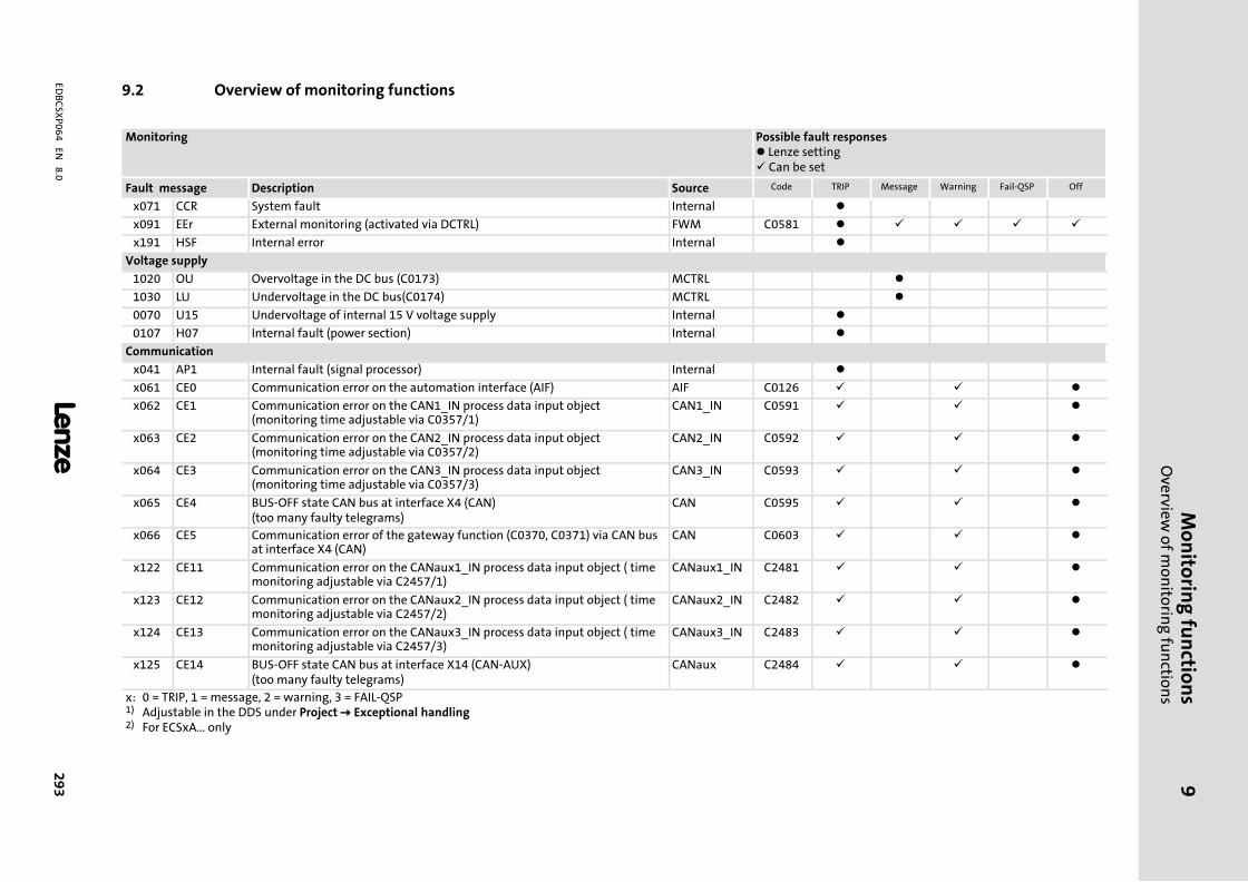
Mo
nito
ring
fun
ction
sO
verview o
f mo
nito
ring
fun
ction
s9
� 2
93
EDB
CSX
P0
64
EN 8
.0
9.2 Overview of monitoring functions
Monitoring Possible fault responses� Lenze setting� Can be set
Fault message Description Source Code TRIP Message Warning Fail−QSP Off
x071 CCR System fault Internal �
x091 EEr External monitoring (activated via DCTRL) FWM C0581 � � � � �
x191 HSF Internal error Internal �
Voltage supply
1020 OU Overvoltage in the DC bus (C0173) MCTRL �
1030 LU Undervoltage in the DC bus(C0174) MCTRL �
0070 U15 Undervoltage of internal 15 V voltage supply Internal �
0107 H07 Internal fault (power section) Internal �
Communication
x041 AP1 Internal fault (signal processor) Internal �
x061 CE0 Communication error on the automation interface (AIF) AIF C0126 � � �
x062 CE1 Communication error on the CAN1_IN process data input object(monitoring time adjustable via C0357/1)
CAN1_IN C0591 � � �
x063 CE2 Communication error on the CAN2_IN process data input object(monitoring time adjustable via C0357/2)
CAN2_IN C0592 � � �
x064 CE3 Communication error on the CAN3_IN process data input object(monitoring time adjustable via C0357/3)
CAN3_IN C0593 � � �
x065 CE4 BUS−OFF state CAN bus at interface X4 (CAN)(too many faulty telegrams)
CAN C0595 � � �
x066 CE5 Communication error of the gateway function (C0370, C0371) via CAN busat interface X4 (CAN)
CAN C0603 � � �
x122 CE11 Communication error on the CANaux1_IN process data input object ( timemonitoring adjustable via C2457/1)
CANaux1_IN C2481 � � �
x123 CE12 Communication error on the CANaux2_IN process data input object ( timemonitoring adjustable via C2457/2)
CANaux2_IN C2482 � � �
x124 CE13 Communication error on the CANaux3_IN process data input object ( timemonitoring adjustable via C2457/3)
CANaux3_IN C2483 � � �
x125 CE14 BUS−OFF state CAN bus at interface X14 (CAN−AUX)(too many faulty telegrams)
CANaux C2484 � � �
x: 0 = TRIP, 1 = message, 2 = warning, 3 = FAIL−QSP1) Adjustable in the DDS under Project � Exceptional handling2) For ECSxA... only
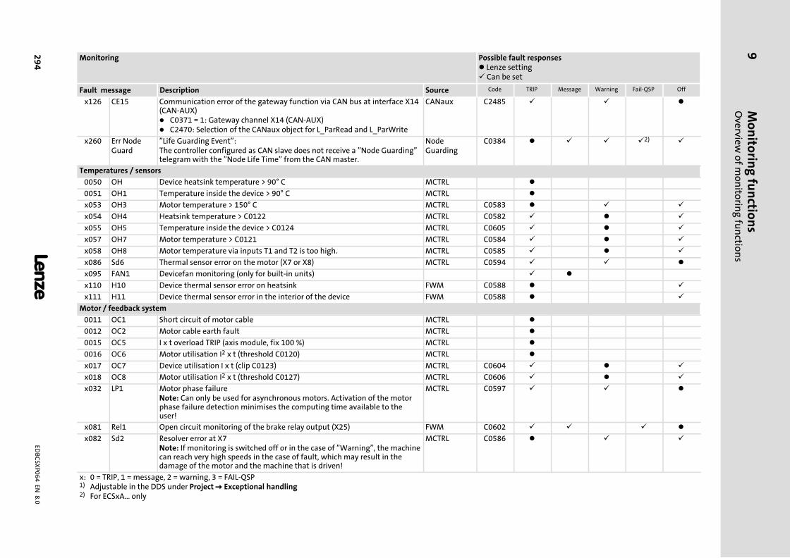
Mo
nito
ring
fun
ction
sO
verview o
f mo
nito
ring
fun
ction
s9
� 2
94
EDB
CSX
P0
64
EN 8
.0
Possible fault responses� Lenze setting� Can be set
Monitoring
OffFail−QSPWarningMessageTRIPCodeSourceDescriptionFault message
x126 CE15 Communication error of the gateway function via CAN bus at interface X14(CAN−AUX)� C0371 = 1: Gateway channel X14 (CAN−AUX)� C2470: Selection of the CANaux object for L_ParRead and L_ParWrite
CANaux C2485 � � �
x260 Err NodeGuard
"Life Guarding Event":The controller configured as CAN slave does not receive a "Node Guarding"telegram with the "Node Life Time" from the CAN master.
NodeGuarding
C0384 � � � �2) �
Temperatures / sensors
0050 OH Device heatsink temperature > 90° C MCTRL �
0051 OH1 Temperature inside the device > 90° C MCTRL �
x053 OH3 Motor temperature > 150° C MCTRL C0583 � � �
x054 OH4 Heatsink temperature > C0122 MCTRL C0582 � � �
x055 OH5 Temperature inside the device > C0124 MCTRL C0605 � � �
x057 OH7 Motor temperature > C0121 MCTRL C0584 � � �
x058 OH8 Motor temperature via inputs T1 and T2 is too high. MCTRL C0585 � � �
x086 Sd6 Thermal sensor error on the motor (X7 or X8) MCTRL C0594 � � �
x095 FAN1 Devicefan monitoring (only for built−in units) � �
x110 H10 Device thermal sensor error on heatsink FWM C0588 � �
x111 H11 Device thermal sensor error in the interior of the device FWM C0588 � �
Motor / feedback system
0011 OC1 Short circuit of motor cable MCTRL �
0012 OC2 Motor cable earth fault MCTRL �
0015 OC5 I x t overload TRIP (axis module, fix 100 %) MCTRL �
0016 OC6 Motor utilisation I2 x t (threshold C0120) MCTRL �
x017 OC7 Device utilisation I x t (clip C0123) MCTRL C0604 � � �
x018 OC8 Motor utilisation I2 x t (threshold C0127) MCTRL C0606 � � �
x032 LP1 Motor phase failureNote: Can only be used for asynchronous motors. Activation of the motorphase failure detection minimises the computing time available to theuser!
MCTRL C0597 � � �
x081 Rel1 Open circuit monitoring of the brake relay output (X25) FWM C0602 � � � �
x082 Sd2 Resolver error at X7Note: If monitoring is switched off or in the case of "Warning", the machinecan reach very high speeds in the case of fault, which may result in thedamage of the motor and the machine that is driven!
MCTRL C0586 � � �
x: 0 = TRIP, 1 = message, 2 = warning, 3 = FAIL−QSP1) Adjustable in the DDS under Project � Exceptional handling2) For ECSxA... only
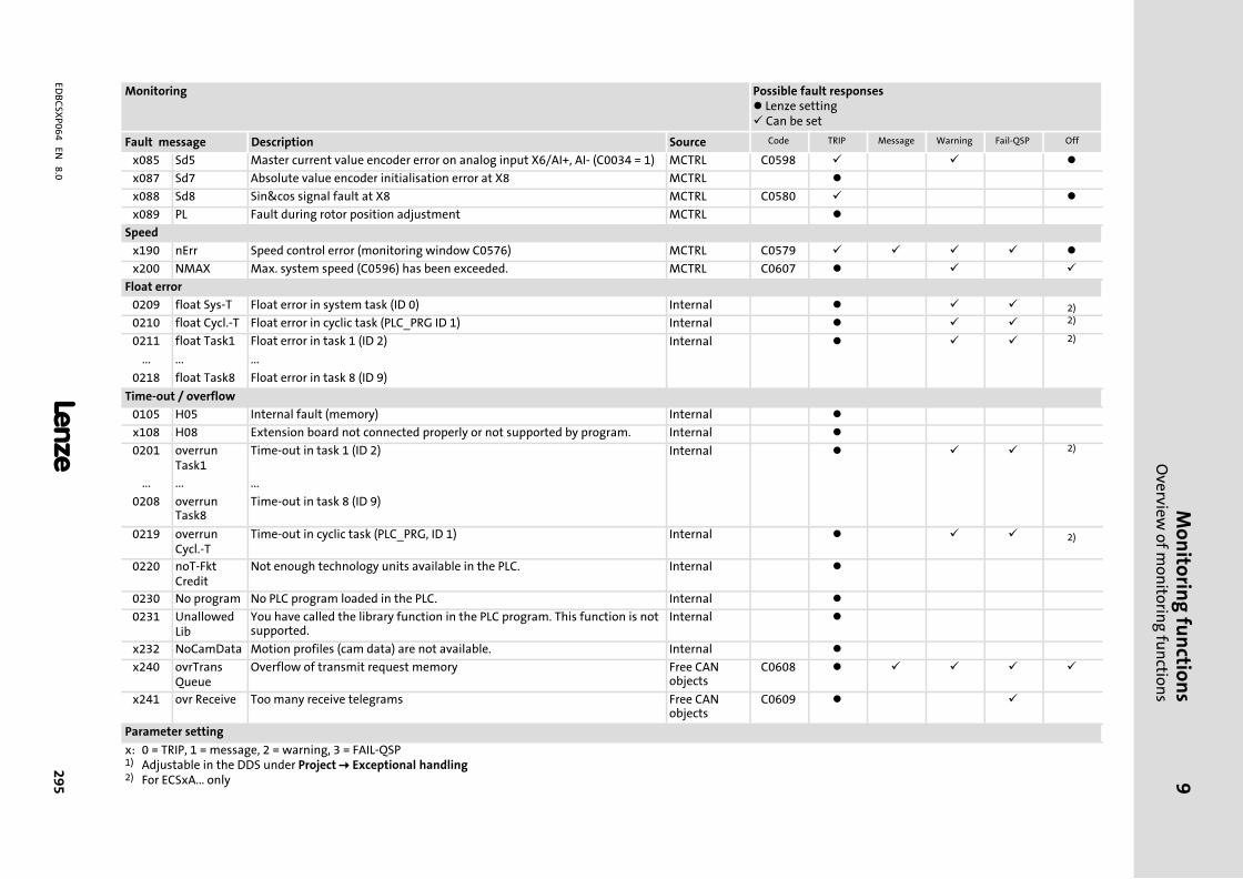
Mo
nito
ring
fun
ction
sO
verview o
f mo
nito
ring
fun
ction
s9
� 2
95
EDB
CSX
P0
64
EN 8
.0
Possible fault responses� Lenze setting� Can be set
Monitoring
OffFail−QSPWarningMessageTRIPCodeSourceDescriptionFault message
x085 Sd5 Master current value encoder error on analog input X6/AI+, AI− (C0034 = 1) MCTRL C0598 � � �
x087 Sd7 Absolute value encoder initialisation error at X8 MCTRL �
x088 Sd8 Sin&cos signal fault at X8 MCTRL C0580 � �
x089 PL Fault during rotor position adjustment MCTRL �
Speed
x190 nErr Speed control error (monitoring window C0576) MCTRL C0579 � � � � �
x200 NMAX Max. system speed (C0596) has been exceeded. MCTRL C0607 � � �
Float error
0209 float Sys−T Float error in system task (ID 0) Internal � � � 2)
0210 float Cycl.−T Float error in cyclic task (PLC_PRG ID 1) Internal � � � 2)
0211 float Task1 Float error in task 1 (ID 2) Internal � � � 2)
... ... ...
0218 float Task8 Float error in task 8 (ID 9)
Time−out / overflow
0105 H05 Internal fault (memory) Internal �
x108 H08 Extension board not connected properly or not supported by program. Internal �
0201 overrunTask1
Time−out in task 1 (ID 2) Internal � � � 2)
... ... ...
0208 overrunTask8
Time−out in task 8 (ID 9)
0219 overrunCycl.−T
Time−out in cyclic task (PLC_PRG, ID 1) Internal � � � 2)
0220 noT−FktCredit
Not enough technology units available in the PLC. Internal �
0230 No program No PLC program loaded in the PLC. Internal �
0231 UnallowedLib
You have called the library function in the PLC program. This function is notsupported.
Internal �
x232 NoCamData Motion profiles (cam data) are not available. Internal �
x240 ovrTransQueue
Overflow of transmit request memory Free CANobjects
C0608 � � � � �
x241 ovr Receive Too many receive telegrams Free CANobjects
C0609 � �
Parameter setting
x: 0 = TRIP, 1 = message, 2 = warning, 3 = FAIL−QSP1) Adjustable in the DDS under Project � Exceptional handling2) For ECSxA... only

Mo
nito
ring
fun
ction
sO
verview o
f mo
nito
ring
fun
ction
s9
� 2
96
EDB
CSX
P0
64
EN 8
.0
Possible fault responses� Lenze setting� Can be set
Monitoring
OffFail−QSPWarningMessageTRIPCodeSourceDescriptionFault message
0072 PR1 Check sum error in parameter set 1 Internal �
0074 PEr Program error Internal �
0075 PR0 Error in the parameter sets Internal �
0079 PI Error during parameter initialisation Internal �
0080 PR6 � For ECSxS/P/M:Internal fault� For ECSxA: Too many user codes
Internal �
Application−specific fault messages
2402 PosPosLimit Warning: Positive software limit position (C3040) has been reached. �
2403 NegPosLimit
Warning: Negative software limit position (C3041) has been reached. �
2404 FollowErrWarn
Warning: Following error tolerance (C3030) has been reached. �
2422 InvProfData Impermissible positioning profile parameters �
2423 OverflIntPos Position setpoint overflow �
2424 SWLimOut−OfRan
Warning: Impermissible setting of the software limit positions(C3040/C3041)
�
3400 PosLimitSw FAIL−QSP: Positive hardware limit switch has been approached. �
3401 NegLimitSw FAIL−QSP: Negative hardware limit switch has been approached. �
3402 PosPosLimit FAIL−QSP: Positive software limit position (C3040) has been reached. �
3403 NegPosLimit
FAIL−QSP: Negative software limit position (C3041) has been reached. �
3405 FollowErrFail
FAIL−QSP: Following error tolerance (C3031) has been reached. �
3406 HomePosErr Home position has not been reached. �
3409 MaxVelErr Max. speed in C1240 is set too high. �
3417 InSftw−Limits
FAIL−QSP: Impermissible setting of the software limit positions(C3040/C3041)
�
0425 InvHoming−Offs
Reference measuring system offset (C3012) is invalid. �
3500 ExtTripSet External fault has been triggered. �
3501 InvTpProfNo
Invalid positioning profile number with touch probe positioning �
3503 InvalidFeedb
Impermissible feedback system selection �
3504 InvalidOS Version of operating system is not compatible. �
x: 0 = TRIP, 1 = message, 2 = warning, 3 = FAIL−QSP1) Adjustable in the DDS under Project � Exceptional handling2) For ECSxA... only

Monitoring functionsConfiguring monitoring functions
Monitoring times for process data input objects
9
� 297EDBCSXP064 EN 8.0
9.3 Configuring monitoring functions
9.3.1 Monitoring times for process data input objects
Fault message Monitoring function System variable Possible response
TRIP Message
Warning
Off
x062 CE1 Communication error at theprocess data input objectCAN1_IN
CAN_bCe1CommErrCanIn1_b � � �
x063 CE2 Communication error at theprocess data input objectCAN2_IN
CAN_bCe2CommErrCanIn2_b � � �
x064 CE3 Communication error at theprocess data input objectCAN3_IN
CAN_bCe3CommErrCanIn3_b � � �
x065 CE4 BUS−OFF state of the CAN busat interface X4 (CAN)
CAN_bCe4BusOffState_b � � �
x122 CE11 Communication error at theprocess data input objectCANaux1_IN
CANaux_bCe1CommErrCanIn1_b
� � �
x123 CE12 Communication error at theprocess data input objectCANaux2_IN
CANaux_bCe2CommErrCanIn2_b
� � �
x124 CE13 Communication error at theprocess data input objectCANaux3_IN
CANaux_bCe3CommErrCanIn3_b
� � �
x125 CE14 BUS−OFF state of the CAN busat interface X14 (CAN−AUX)
CANaux_bCe4BusOffState_b � � �
� Default setting�Setting possible
Each process data input object can monitor whether a telegram has been received withina specified time. As soon as a telegram arrives, the corresponding monitoring time(C0357/C02457) is restarted ("retriggerable monoflop" function).
Code Possible settings IMPORTANT
No. Designation Lenze/{Appl.}
Selection
C0357 Monitoring time for CAN1...3_IN(CAN bus interface X4)
� 297
1 CE monit time 3000 1 {1 ms} 65000 CE1 monitoring time
2 CE monit time 3000 CE2 monitoring time
3 CE monit time 3000 CE3 monitoring time

Monitoring functionsConfiguring monitoring functionsMonitoring times for process data input objects
9
� 298 EDBCSXP064 EN 8.0
IMPORTANTPossible settingsCode
SelectionLenze/{Appl.}
DesignationNo.
C2457 Monitoring time forCANaux1...3_IN (CAN businterface X14)
� 297
1 CE monit time 3000 1 {1 ms} 65000 CE11 monitoring time
2 CE monit time 3000 CE12 monitoring time
3 CE monit time 3000 CE13 monitoring time
The following responses can be set for communication errors:
ƒ 0 = Error (TRIP) − controller sets controller inhibit (CINH)
ƒ 2 = Warning
ƒ 3 = Monitoring is switched off
Codes for setting the response to the monitoring functions:
CAN bus interface Code Monitoring
X4ECSxS/P/M: MotionBus (CAN)ECSxA: System bus (CAN)
C0591 CAN1_IN ("CE1")
C0592 CAN2_IN ("CE2")
C0593 CAN3_IN ("CE3")
C0595 Bus off ("CE4")
C0603 Gateway function ("CE5")
X14System bus (CAN)
C2481 CANaux1_IN ("CE11")
C2482 CANaux2_IN ("CE12")
C2483 CANaux3_IN ("CE13")
C2484 Bus off ("CE14")
C2485 Gateway function ("CE15")
The input signals (CAN1...3_IN/CANaux1...3_IN) can also be used as binary output signals,e.g. for the assignment of the output terminal.
Bus off
If the controller disconnects from the CAN bus due to faulty telegrams, the signal"BusOffState" (CE4/CE14) is set.
"BusOffState" can activate an error (TRIP) or warning. The signal can also be switched off.The response is set under C0595/C2484. You can also assign the terminal output for this.
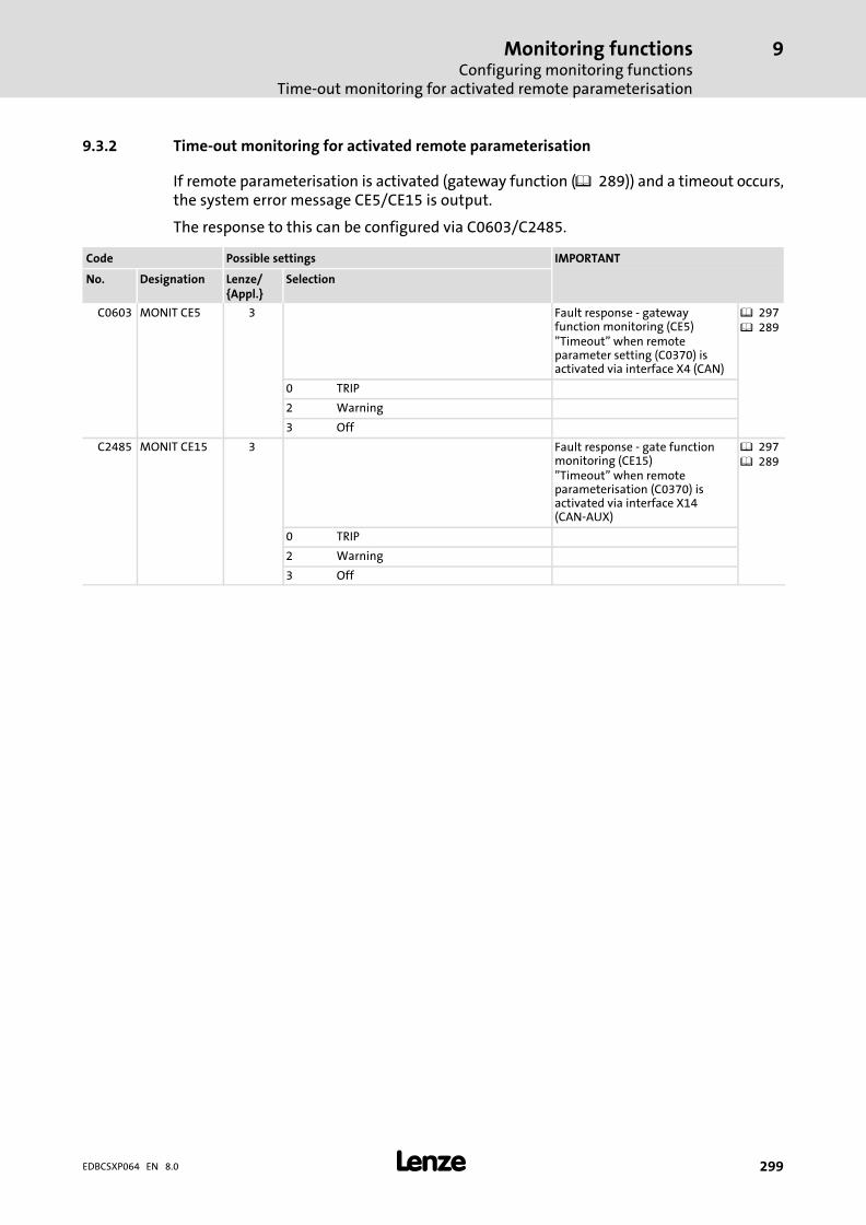
Monitoring functionsConfiguring monitoring functions
Time−out monitoring for activated remote parameterisation
9
� 299EDBCSXP064 EN 8.0
9.3.2 Time−out monitoring for activated remote parameterisation
If remote parameterisation is activated (gateway function ( 289)) and a timeout occurs,the system error message CE5/CE15 is output.
The response to this can be configured via C0603/C2485.
Code Possible settings IMPORTANT
No. Designation Lenze/{Appl.}
Selection
C0603 MONIT CE5 3 Fault response − gatewayfunction monitoring (CE5)"Timeout" when remoteparameter setting (C0370) isactivated via interface X4 (CAN)
� 297� 289
0 TRIP
2 Warning
3 Off
C2485 MONIT CE15 3 Fault response − gate functionmonitoring (CE15)"Timeout" when remoteparameterisation (C0370) isactivated via interface X14(CAN−AUX)
� 297� 289
0 TRIP
2 Warning
3 Off
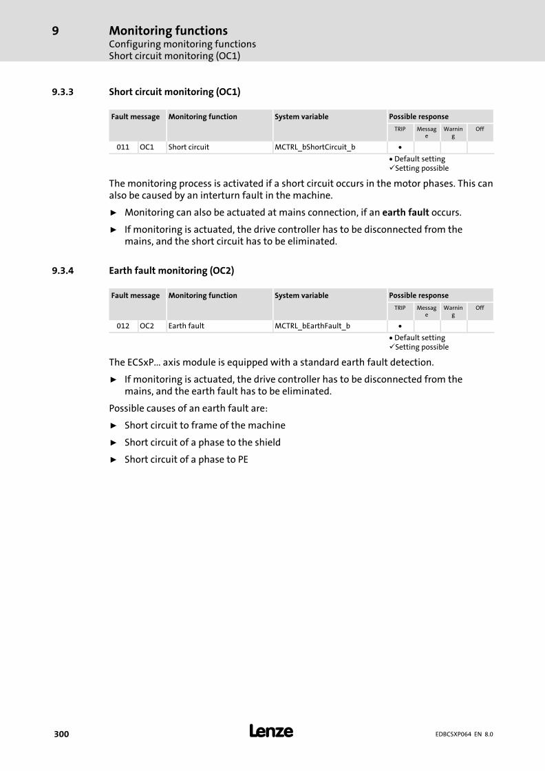
Monitoring functionsConfiguring monitoring functionsShort circuit monitoring (OC1)
9
� 300 EDBCSXP064 EN 8.0
9.3.3 Short circuit monitoring (OC1)
Fault message Monitoring function System variable Possible response
TRIP Message
Warning
Off
011 OC1 Short circuit MCTRL_bShortCircuit_b �
� Default setting�Setting possible
The monitoring process is activated if a short circuit occurs in the motor phases. This canalso be caused by an interturn fault in the machine.
ƒ Monitoring can also be actuated at mains connection, if an earth fault occurs.
ƒ If monitoring is actuated, the drive controller has to be disconnected from themains, and the short circuit has to be eliminated.
9.3.4 Earth fault monitoring (OC2)
Fault message Monitoring function System variable Possible response
TRIP Message
Warning
Off
012 OC2 Earth fault MCTRL_bEarthFault_b �
� Default setting�Setting possible
The ECSxP... axis module is equipped with a standard earth fault detection.
ƒ If monitoring is actuated, the drive controller has to be disconnected from themains, and the earth fault has to be eliminated.
Possible causes of an earth fault are:
ƒ Short circuit to frame of the machine
ƒ Short circuit of a phase to the shield
ƒ Short circuit of a phase to PE
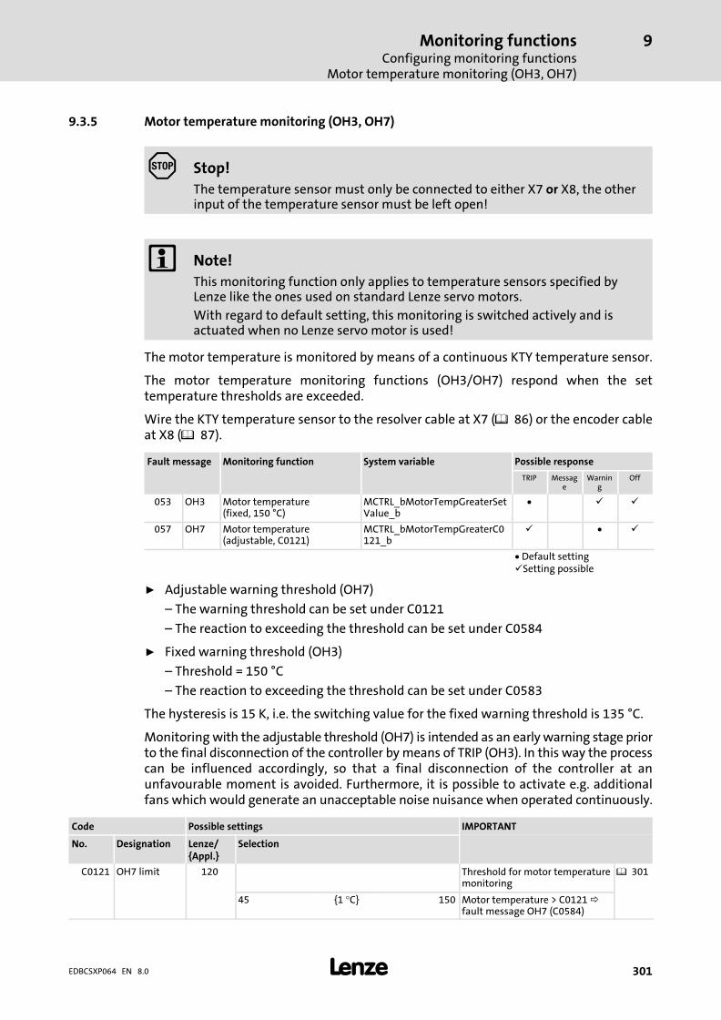
Monitoring functionsConfiguring monitoring functions
Motor temperature monitoring (OH3, OH7)
9
� 301EDBCSXP064 EN 8.0
9.3.5 Motor temperature monitoring (OH3, OH7)
� Stop!
The temperature sensor must only be connected to either X7 or X8, the otherinput of the temperature sensor must be left open!
� Note!
This monitoring function only applies to temperature sensors specified byLenze like the ones used on standard Lenze servo motors.
With regard to default setting, this monitoring is switched actively and isactuated when no Lenze servo motor is used!
The motor temperature is monitored by means of a continuous KTY temperature sensor.
The motor temperature monitoring functions (OH3/OH7) respond when the settemperature thresholds are exceeded.
Wire the KTY temperature sensor to the resolver cable at X7 (� 86) or the encoder cableat X8 (� 87).
Fault message Monitoring function System variable Possible response
TRIP Message
Warning
Off
053 OH3 Motor temperature(fixed, 150 °C)
MCTRL_bMotorTempGreaterSetValue_b
� � �
057 OH7 Motor temperature(adjustable, C0121)
MCTRL_bMotorTempGreaterC0121_b
� � �
� Default setting�Setting possible
ƒ Adjustable warning threshold (OH7)
– The warning threshold can be set under C0121
– The reaction to exceeding the threshold can be set under C0584
ƒ Fixed warning threshold (OH3)
– Threshold = 150 °C
– The reaction to exceeding the threshold can be set under C0583
The hysteresis is 15 K, i.e. the switching value for the fixed warning threshold is 135 °C.
Monitoring with the adjustable threshold (OH7) is intended as an early warning stage priorto the final disconnection of the controller by means of TRIP (OH3). In this way the processcan be influenced accordingly, so that a final disconnection of the controller at anunfavourable moment is avoided. Furthermore, it is possible to activate e.g. additionalfans which would generate an unacceptable noise nuisance when operated continuously.
Code Possible settings IMPORTANT
No. Designation Lenze/{Appl.}
Selection
C0121 OH7 limit 120 Threshold for motor temperaturemonitoring
� 301
45 {1 °C} 150 Motor temperature > C0121 fault message OH7 (C0584)

Monitoring functionsConfiguring monitoring functionsMotor temperature monitoring (OH3, OH7)
9
� 302 EDBCSXP064 EN 8.0
IMPORTANTPossible settingsCode
SelectionLenze/{Appl.}
DesignationNo.
C0583 MONIT OH3 0 Fault response − monitoring ofmotor temperature (fixedtemperature threshold).Detection through KTY thermalsensor via resolver input X7 orencoder input X8.
� 301
0 TRIP
2 Warning
3 Off
C0584 MONIT OH7 2 Fault response − motortemperature monitoringTemperature threshold can beset under C0121.Detection through KTY thermalsensor via resolver input X7 orencoder input X8.Only effective if OH3 is switchedon under C0583.
� 301
0 TRIP
2 Warning
3 Off
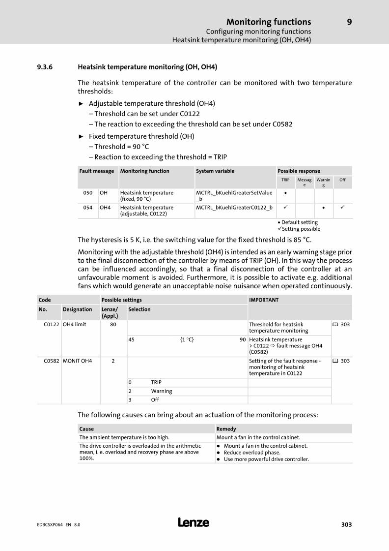
Monitoring functionsConfiguring monitoring functions
Heatsink temperature monitoring (OH, OH4)
9
� 303EDBCSXP064 EN 8.0
9.3.6 Heatsink temperature monitoring (OH, OH4)
The heatsink temperature of the controller can be monitored with two temperaturethresholds:
ƒ Adjustable temperature threshold (OH4)
– Threshold can be set under C0122
– The reaction to exceeding the threshold can be set under C0582
ƒ Fixed temperature threshold (OH)
– Threshold = 90 °C
– Reaction to exceeding the threshold = TRIP
Fault message Monitoring function System variable Possible response
TRIP Message
Warning
Off
050 OH Heatsink temperature(fixed, 90 °C)
MCTRL_bKuehlGreaterSetValue_b
�
054 OH4 Heatsink temperature(adjustable, C0122)
MCTRL_bKuehlGreaterC0122_b � � �
� Default setting�Setting possible
The hysteresis is 5 K, i.e. the switching value for the fixed threshold is 85 °C.
Monitoring with the adjustable threshold (OH4) is intended as an early warning stage priorto the final disconnection of the controller by means of TRIP (OH). In this way the processcan be influenced accordingly, so that a final disconnection of the controller at anunfavourable moment is avoided. Furthermore, it is possible to activate e.g. additionalfans which would generate an unacceptable noise nuisance when operated continuously.
Code Possible settings IMPORTANT
No. Designation Lenze/{Appl.}
Selection
C0122 OH4 limit 80 Threshold for heatsinktemperature monitoring
� 303
45 {1 °C} 90 Heatsink temperature> C0122 fault message OH4(C0582)
C0582 MONIT OH4 2 Setting of the fault response −monitoring of heatsinktemperature in C0122
� 303
0 TRIP
2 Warning
3 Off
The following causes can bring about an actuation of the monitoring process:
Cause Remedy
The ambient temperature is too high. Mount a fan in the control cabinet.
The drive controller is overloaded in the arithmeticmean, i.� e. overload and recovery phase are above100�%.
� Mount a fan in the control cabinet.� Reduce overload phase.� Use more powerful drive controller.
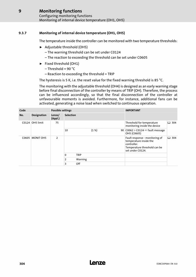
Monitoring functionsConfiguring monitoring functionsMonitoring of internal device temperature (OH1, OH5)
9
� 304 EDBCSXP064 EN 8.0
9.3.7 Monitoring of internal device temperature (OH1, OH5)
The temperature inside the controller can be monitored with two temperature thresholds:
ƒ Adjustable threshold (OH5)
– The warning threshold can be set under C0124
– The reaction to exceeding the threshold can be set under C0605
ƒ Fixed threshold (OH1)
– Threshold = 90 °C
– Reaction to exceeding the threshold = TRIP
The hysteresis is 5 K, i.e. the reset value for the fixed warning threshold is 85 °C.
The monitoring with the adjustable threshold (OH4) is designed as an early warning stagebefore final disconnection of the controller by means of TRIP (OH). Therefore, the processcan be influenced accordingly, so that the final disconnection of the controller atunfavourable moments is avoided. Furthermore, for instance, additional fans can beactivated, generating a noise load when switched to continuous operation.
Code Possible settings IMPORTANT
No. Designation Lenze/{Appl.}
Selection
C0124 OH5 limit 75 Threshold for temperaturemonitoring inside the device
� 304
10 {1 %} 90 C0062 > C0124 fault messageOH5 (C0605)
C0605 MONIT OH5 2 Fault response − monitoring oftemperature inside thecontroller.Temperature threshold can beset under C0124.
� 304
0 TRIP
2 Warning
3 Off
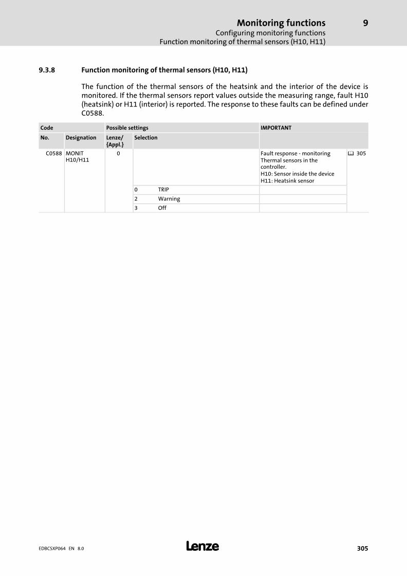
Monitoring functionsConfiguring monitoring functions
Function monitoring of thermal sensors (H10, H11)
9
� 305EDBCSXP064 EN 8.0
9.3.8 Function monitoring of thermal sensors (H10, H11)
The function of the thermal sensors of the heatsink and the interior of the device ismonitored. If the thermal sensors report values outside the measuring range, fault H10(heatsink) or H11 (interior) is reported. The response to these faults can be defined underC0588.
Code Possible settings IMPORTANT
No. Designation Lenze/{Appl.}
Selection
C0588 MONITH10/H11
0 Fault response − monitoringThermal sensors in thecontroller.H10: Sensor inside the deviceH11: Heatsink sensor
� 305
0 TRIP
2 Warning
3 Off
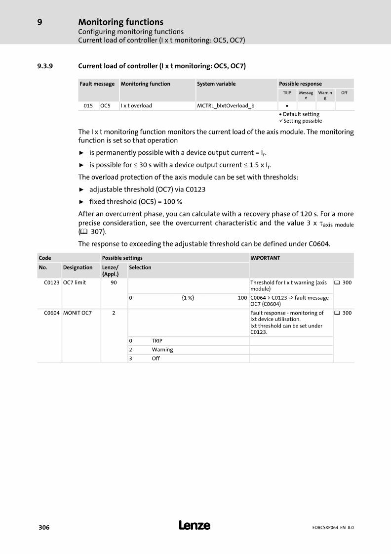
Monitoring functionsConfiguring monitoring functionsCurrent load of controller (I x t monitoring: OC5, OC7)
9
� 306 EDBCSXP064 EN 8.0
9.3.9 Current load of controller (I x t monitoring: OC5, OC7)
Fault message Monitoring function System variable Possible response
TRIP Message
Warning
Off
015 OC5 I x t overload MCTRL_bIxtOverload_b �
� Default setting�Setting possible
The I x t monitoring function monitors the current load of the axis module. The monitoringfunction is set so that operation
ƒ is permanently possible with a device output current = Ir.
ƒ is possible for � 30 s with a device output current � 1.5 x Ir.
The overload protection of the axis module can be set with thresholds:
ƒ adjustable threshold (OC7) via C0123
ƒ fixed threshold (OC5) = 100 %
After an overcurrent phase, you can calculate with a recovery phase of 120 s. For a moreprecise consideration, see the overcurrent characteristic and the value 3 x �axis module(� 307).
The response to exceeding the adjustable threshold can be defined under C0604.
Code Possible settings IMPORTANT
No. Designation Lenze/{Appl.}
Selection
C0123 OC7 limit 90 Threshold for I x t warning (axismodule)
� 300
0 {1 %} 100 C0064 > C0123 fault messageOC7 (C0604)
C0604 MONIT OC7 2 Fault response − monitoring ofIxt device utilisation.Ixt threshold can be set underC0123.
� 300
0 TRIP
2 Warning
3 Off
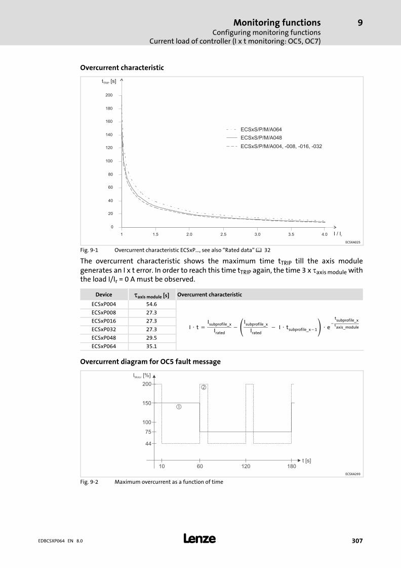
Monitoring functionsConfiguring monitoring functions
Current load of controller (I x t monitoring: OC5, OC7)
9
� 307EDBCSXP064 EN 8.0
Overcurrent characteristic
0
20
40
60
80
100
120
140
160
180
200
1 1.5 2.0 2.5 3.0 3.5 4.0
t [s]TRIP
I / Ir
ECSxS/P/M/A004, -008, -016, -032
ECSxS/P/M/A048
ECSxS/P/M/A064
ECSXA025
Fig. 9−1 Overcurrent characteristic ECSxP..., see also �Rated data� � 32
The overcurrent characteristic shows the maximum time tTRIP till the axis modulegenerates an I x t error. In order to reach this time tTRIP again, the time 3 x �axis module withthe load I/Ir = 0 A must be observed.
Device �axis module [s] Overcurrent characteristic
ECSxP004 54.6
I � t �Isubprofile_x
Irated�Isubprofile_x
Irated� �� I � tsubprofile_x�1 � e
�tsubprofile_x�axis_module
ECSxP008 27.3
ECSxP016 27.3
ECSxP032 27.3
ECSxP048 29.5
ECSxP064 35.1
Overcurrent diagram for OC5 fault message
150
100
75
200
I [%]Motor
10 60 120 180t [s]
44
�
�
ECSXA293
Fig. 9−2 Maximum overcurrent as a function of time
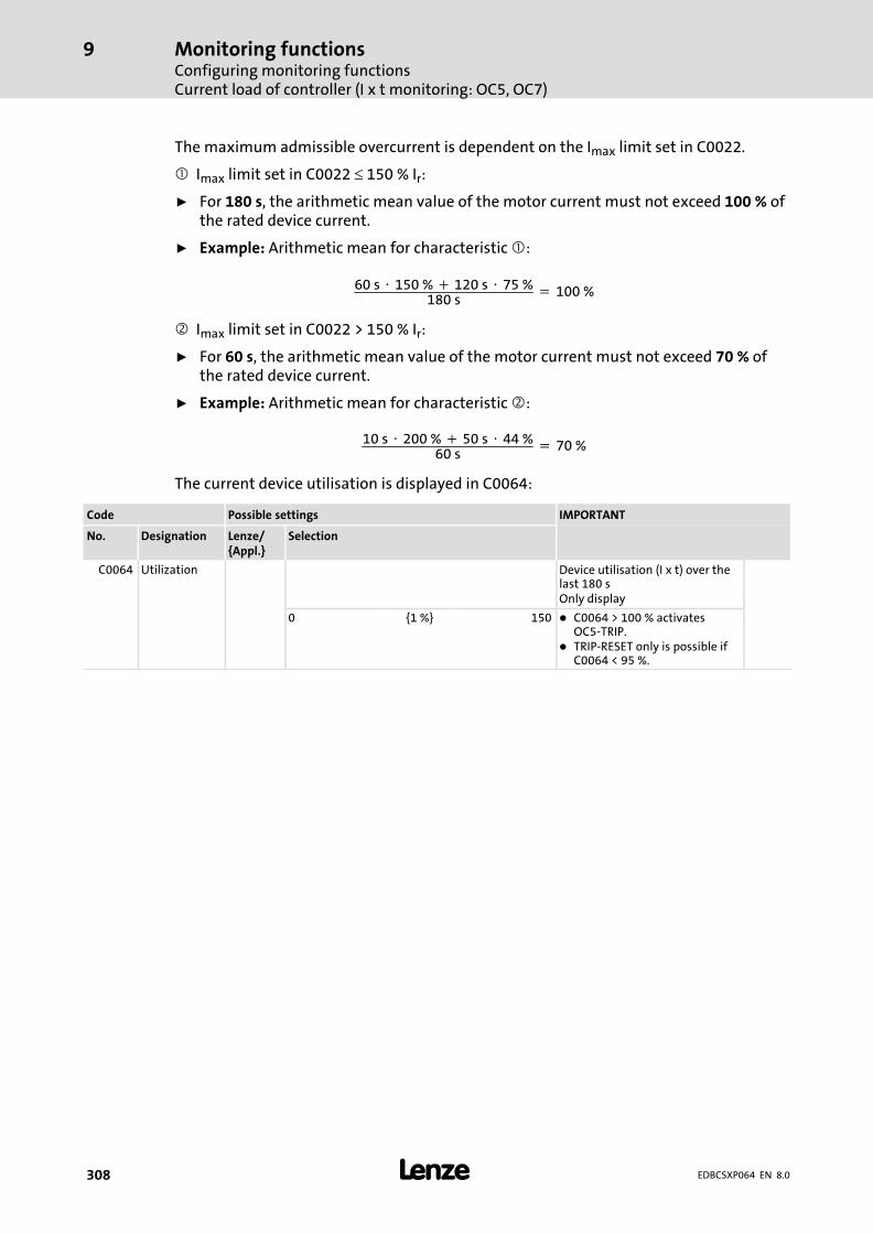
Monitoring functionsConfiguring monitoring functionsCurrent load of controller (I x t monitoring: OC5, OC7)
9
� 308 EDBCSXP064 EN 8.0
The maximum admissible overcurrent is dependent on the Imax limit set in C0022.
� Imax limit set in C0022 � 150 % Ir:
ƒ For 180 s, the arithmetic mean value of the motor current must not exceed 100 % ofthe rated device current.
ƒ Example: Arithmetic mean for characteristic �:
60 s � 150 % � 120 s � 75 %180 s
� 100 %
� Imax limit set in C0022 > 150 % Ir:
ƒ For 60 s, the arithmetic mean value of the motor current must not exceed 70 % ofthe rated device current.
ƒ Example: Arithmetic mean for characteristic �:
10 s � 200 % � 50 s � 44 %60 s
� 70 %
The current device utilisation is displayed in C0064:
Code Possible settings IMPORTANT
No. Designation Lenze/{Appl.}
Selection
C0064 Utilization Device utilisation (I x t) over thelast 180 sOnly display
0 {1 %} 150 � C0064 > 100 % activatesOC5−TRIP.
� TRIP−RESET only is possible ifC0064 < 95 %.
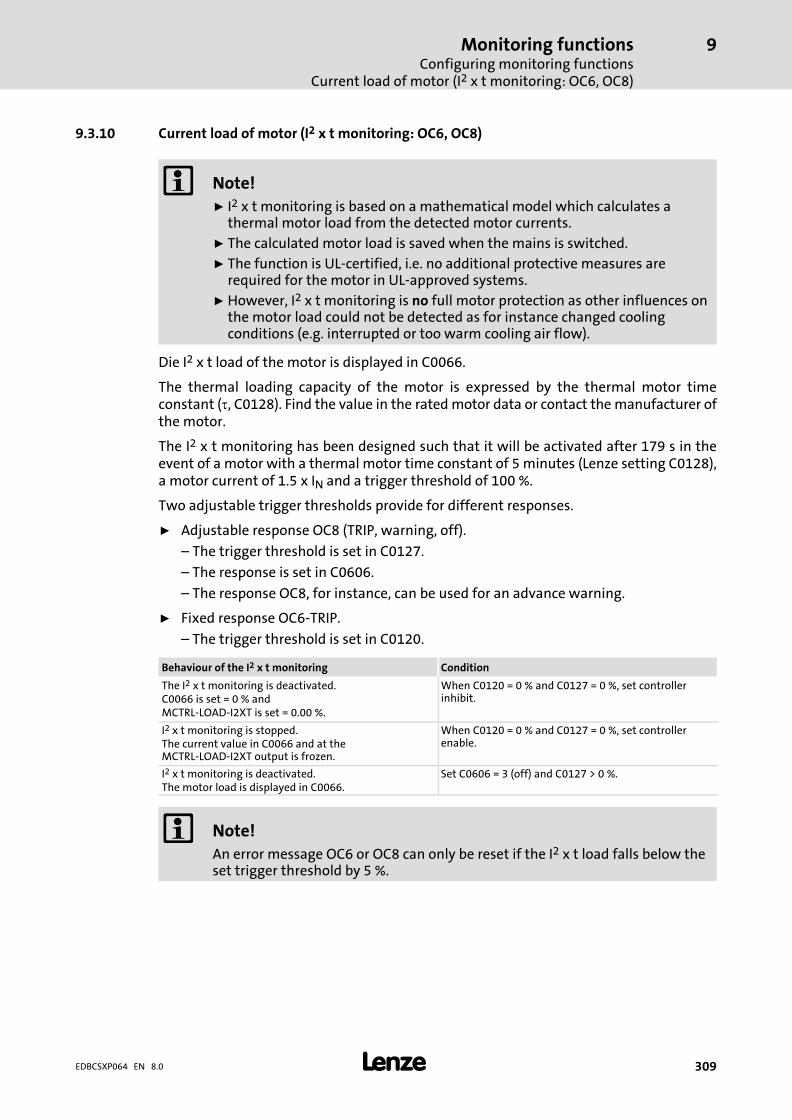
Monitoring functionsConfiguring monitoring functions
Current load of motor (I2 x t monitoring: OC6, OC8)
9
� 309EDBCSXP064 EN 8.0
9.3.10 Current load of motor (I2 x t monitoring: OC6, OC8)
� Note!
ƒ I2 x t monitoring is based on a mathematical model which calculates athermal motor load from the detected motor currents.
ƒ The calculated motor load is saved when the mains is switched.
ƒ The function is UL−certified, i.e. no additional protective measures arerequired for the motor in UL−approved systems.
ƒ However, I2 x t monitoring is no full motor protection as other influences onthe motor load could not be detected as for instance changed coolingconditions (e.g. interrupted or too warm cooling air flow).
Die I2 x t load of the motor is displayed in C0066.
The thermal loading capacity of the motor is expressed by the thermal motor timeconstant (�, C0128). Find the value in the rated motor data or contact the manufacturer ofthe motor.
The I2 x t monitoring has been designed such that it will be activated after 179 s in theevent of a motor with a thermal motor time constant of 5 minutes (Lenze setting C0128),a motor current of 1.5 x IN and a trigger threshold of 100 %.
Two adjustable trigger thresholds provide for different responses.
ƒ Adjustable response OC8 (TRIP, warning, off).
– The trigger threshold is set in C0127.
– The response is set in C0606.
– The response OC8, for instance, can be used for an advance warning.
ƒ Fixed response OC6−TRIP.
– The trigger threshold is set in C0120.
Behaviour of the I2 x t monitoring Condition
The I2 x t monitoring is deactivated.C0066 is set = 0 % andMCTRL−LOAD−I2XT is set = 0.00 %.
When C0120 = 0 % and C0127 = 0 %, set controllerinhibit.
I2 x t monitoring is stopped.The current value in C0066 and at theMCTRL−LOAD−I2XT output is frozen.
When C0120 = 0 % and C0127 = 0 %, set controllerenable.
I2 x t monitoring is deactivated.The motor load is displayed in C0066.
Set C0606 = 3 (off) and C0127 > 0 %.
� Note!
An error message OC6 or OC8 can only be reset if the I2 x t load falls below theset trigger threshold by 5 %.
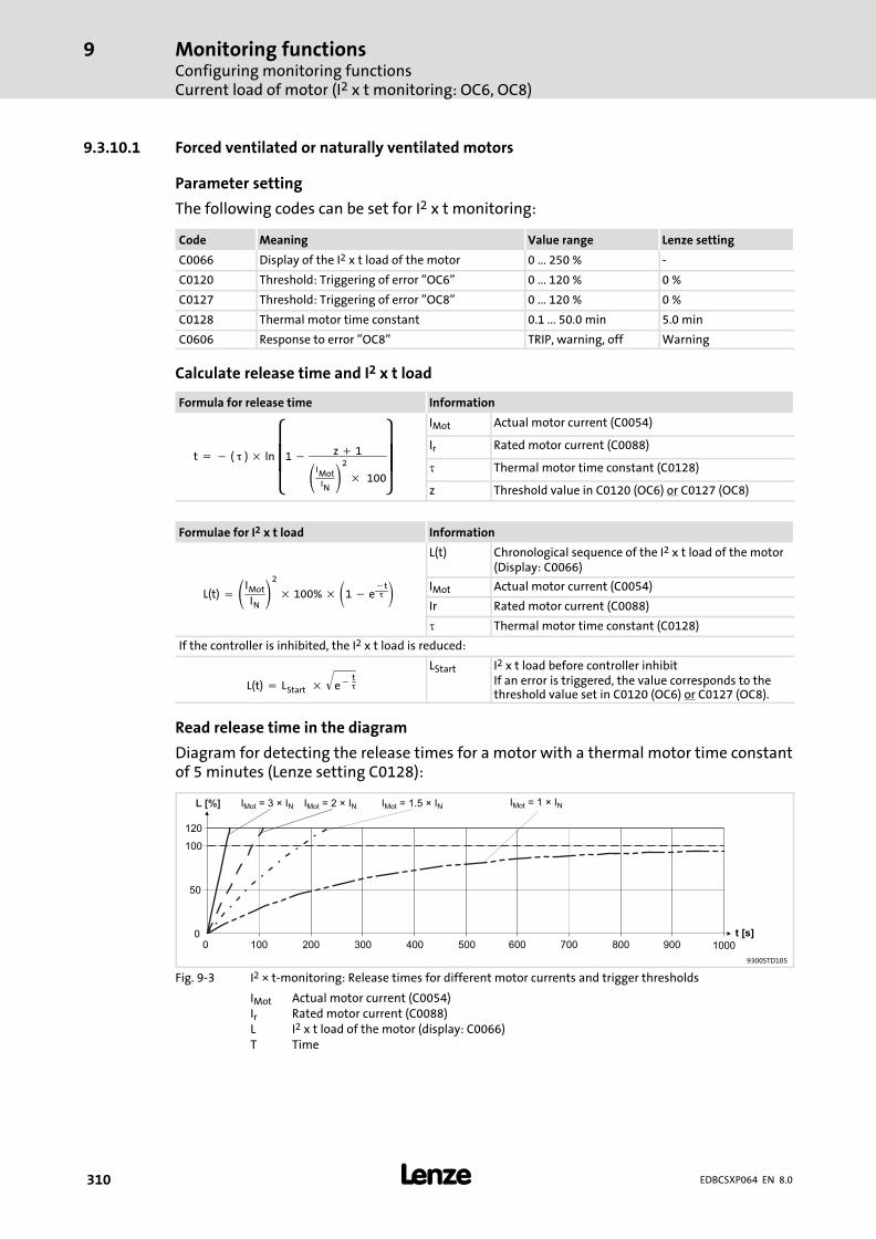
Monitoring functionsConfiguring monitoring functionsCurrent load of motor (I2 x t monitoring: OC6, OC8)
9
� 310 EDBCSXP064 EN 8.0
9.3.10.1 Forced ventilated or naturally ventilated motors
Parameter setting
The following codes can be set for I2 x t monitoring:
Code Meaning Value range Lenze setting
C0066 Display of the I2 x t load of the motor 0 ... 250 % −
C0120 Threshold: Triggering of error "OC6" 0 ... 120 % 0 %
C0127 Threshold: Triggering of error "OC8" 0 ... 120 % 0 %
C0128 Thermal motor time constant 0.1 ... 50.0 min 5.0 min
C0606 Response to error "OC8" TRIP, warning, off Warning
Calculate release time and I2 x t load
Formula for release time Information
t � � (���) � ln����
�1 � z � 1
IMotIN2
�� 100
���
�
IMot Actual motor current (C0054)
Ir Rated motor current (C0088)
� Thermal motor time constant (C0128)
z Threshold value in C0120 (OC6) or C0127 (OC8)
Formulae for I2 x t load Information
L(t) � IMot
IN2
� 100% �1 � e�t�
L(t) Chronological sequence of the I2 x t load of the motor(Display: C0066)
IMot Actual motor current (C0054)
Ir Rated motor current (C0088)
� Thermal motor time constant (C0128)
If the controller is inhibited, the I2 x t load is reduced:
L(t) � LStart� � e��t�
� LStart I2 x t load before controller inhibit
If an error is triggered, the value corresponds to thethreshold value set in C0120 (OC6) or C0127 (OC8).
Read release time in the diagram
Diagram for detecting the release times for a motor with a thermal motor time constantof 5 minutes (Lenze setting C0128):
I = 3 × IMot N
0
50
100
120
0 100 200 300 400 500 600 700 800 900 1000
t [s]
L [%] I = 2 × IMot N I = 1.5 × IMot N I = 1 × IMot N
9300STD105
Fig. 9−3 I2 × t−monitoring: Release times for different motor currents and trigger thresholds
IMot Actual motor current (C0054)Ir Rated motor current (C0088)L I2 x t load of the motor (display: C0066)T Time

Monitoring functionsConfiguring monitoring functions
Current load of motor (I2 x t monitoring: OC6, OC8)
9
� 311EDBCSXP064 EN 8.0
9.3.10.2 Self−ventilated motors
Due to the construction, self−ventilated standard motors are exposed to an increased heatgeneration in the lower speed range compared to forced ventilated motors.
� Warnings!
For complying with the UL 508C standard, you have to set thespeed−dependent evaluation of the permissible torque via code C0129/x.
Parameter setting
The following codes can be set for I2 x t monitoring:
Code Meaning Value range Lenze setting
C0066 Display of the I2 x t load of the motor 0 ... 250 % −
C0120 Threshold: Triggering of error "OC6" 0 ... 120 % 0 %
C0127 Threshold: Triggering of error "OC8" 0 ... 120 % 0 %
C0128 Thermal motor time constant 0.1 ... 50.0 min 5.0 min
C0606 Response to error "OC8" TRIP, warning, off Warning
C0129/1 S1 torque characteristic I1/Irated 10 ... 200 % 100 %
C0129/2 S1 torque characteristics n2/nrated 10 ... 200 % 40 %
Effect of code C0129/x
0
0.9
0 0.1
C0129/2
0.2 0.3 0.4
0.6
0.7
0.8
1.0
1.1
�
�
0.132
�
I / IN
n / nN
C0129/1
�
9300STD350
Fig. 9−4 Working point in the range of characteristic lowering
The lowered speed / torque characteristic (Fig. 9−4) reduces the permissible thermal loadof self−ventilated standard motors. The characteristic is a line the definition of whichrequires two points:
ƒ Point : Definition with C0129/1
This value also enables an increase of the maximally permissible load.
ƒ Point �: Definition with C0129/2
With increasing speeds, the maximally permissible load remains unchanged(IMot = Irated).
In Fig. 9−4, the motor speed and the corresponding permissible motor torque (�) can beread for each working point (�on the characteristic ( ) ... �). � can also be calculatedusing the values in C0129/1and C0129/2 (evaluation coefficient "y", 312).

Monitoring functionsConfiguring monitoring functionsCurrent load of motor (I2 x t monitoring: OC6, OC8)
9
� 312 EDBCSXP064 EN 8.0
Calculate release time and I2 x t load
Calculate the release time and the I2 x t load of the motor considering the values inC0129/1 and C0129/2(evaluation coefficient "y").
Formulae for release time Information
y �100% � C0129�1
C0129�2� n
nN� C0129�1
T � � (���) � ln����
�1 � z � 1
IMoty�IN2
�� 100
���
�
T Release time of the I2 x t monitoring
� Thermal motor time constant (C0128)
In Function: Natural logarithm
IMot Actual motor current (C0054)
Ir Rated motor current (C0088)
z Threshold value in C0120 (OC6) or C0127 (OC8)
y Evaluation coefficient
nrated Rated speed (C0087)
Formulae for I2 x t load Information
L(t) � IMot
y � IN2
� 100% �1 � e�t�
L(t) Chronological sequence of the I2 x t load of the motor(Display: C0066)
y Evaluation coefficient
IMot Actual motor current (C0054)
Ir Rated motor current (C0088)
� Thermal motor time constant (C0128)
If the controller is inhibited, the I2 x t load is reduced:
L(t) � LStart� � e��t�
� LStart I2 x t load before controller inhibit
If an error is triggered, the value corresponds to thethreshold value set in C0120 (OC6) or C0127 (OC8).
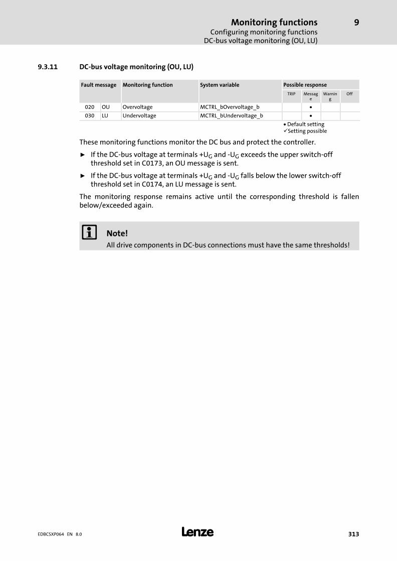
Monitoring functionsConfiguring monitoring functions
DC−bus voltage monitoring (OU, LU)
9
� 313EDBCSXP064 EN 8.0
9.3.11 DC−bus voltage monitoring (OU, LU)
Fault message Monitoring function System variable Possible response
TRIP Message
Warning
Off
020 OU Overvoltage MCTRL_bOvervoltage_b �
030 LU Undervoltage MCTRL_bUndervoltage_b �
� Default setting�Setting possible
These monitoring functions monitor the DC bus and protect the controller.
ƒ If the DC−bus voltage at terminals +UG and −UG exceeds the upper switch−offthreshold set in C0173, an OU message is sent.
ƒ If the DC−bus voltage at terminals +UG and −UG falls below the lower switch−offthreshold set in C0174, an LU message is sent.
The monitoring response remains active until the corresponding threshold is fallenbelow/exceeded again.
� Note!
All drive components in DC−bus connections must have the same thresholds!

Monitoring functionsConfiguring monitoring functionsDC−bus voltage monitoring (OU, LU)
9
� 314 EDBCSXP064 EN 8.0
Switch−off and switch−on thresholds
ƒ The switch−off threshold defines the voltage level of the DC−bus voltage, at whichthe pulse inhibit is activated.
ƒ The switch−off and switch−on thresholds dependent on C0173 can be gathered fromthe following table:
Selection Mains voltage Brake unit LU message(Undervoltage)
OU message(Overvoltage)
C0173 Power supply module[V AC]
Setting[V DC]
Resetting[V DC]
Setting[V DC]
Resetting[V DC]
0 230 yes/no 130 275 400 390
1 400 yes/no 285 430 800 790
2 400 ... 460 yes/no 328 473 800 790
3 480 no 342 487 800 785
4 480 yes 342 487 800 785
10 230 yes/no C0174 C0174 + 5 V 400 390
11 400 (Lenze setting) yes/no C0174 C0174 + 5 V 800 790
12 400 ... 460 yes/no C0174 C0174 + 5 V 800 790
13 480 no C0174 C0174 + 5 V 800 785
14 480 yes C0174 C0174 + 5 V 800 785
� Tip!
If undervoltage is existent for more that 3 s, or if mains connection is carriedout, an entry into the fault memory is effected.
ƒ This operational mode can occur if the control module is fed via theterminals X6/+24 and X6/GND by means of an external supply and themains are disconnected.
ƒ If there is no undervoltage anymore (mains are reconnected again), theentry in the fault memory is not continued, but deleted. This case does notdescribe an error, but a state of the drive controller.
Undervoltages of less than 3 s are interpreted as a fault (e. g. mains fault) andare entered into the fault memory. In this case, the fault memory is updated.

Monitoring functionsConfiguring monitoring functions
DC−bus voltage monitoring (OU, LU)
9
� 315EDBCSXP064 EN 8.0
Code Possible settings IMPORTANT
No. Designation Lenze/{Appl.}
Selection
C0173 UG limit 11 Adaptation of the DC−busvoltage thresholds:� Check during commissioning
and adapt, if necessary.� All drive components in DC
bus connections must havethe same thresholds.– LU = Undervoltage
threshold– OU = Overvoltage threshold
� 126
0 Mains = 230 V � B Operation on 230 V mains withor without brake unitLU = 130 V, OU = 400 V
1 Mains = 400 V � B Operation on 400 V mains withor without brake unitLU = 285 V, OU = 800 V
2 Mains = 460 V � B Operation on 460 V mains withor without brake unitLU = 328 V, OU = 800 V
3 Mains = 480V − B Operation on 480 V mainswithout brake unitLU = 342 V, OU = 800 V
4 Mains = 480V + B Operation on 480 V mains withbrake unitLU = 342 V, OU = 800 V
10 Mains = 230 V � B Operation on 230 V mains withor without brake unitLU = C0174, OU = 400 V
11 Mains = 400 V � B Operation on 400 V mains withor without brake unitLU = C0174, OU = 800 V
12 Mains = 460 V � B Operation on 460 V mains withor without brake unitLU = C0174, OU = 800 V
13 Mains = 480V − B Operation on 480 V mainswithout brake unitLU = C0174, OU = 800 V
14 Mains = 480V + B Operation on 480 V mains withbrake unitLU = C0174, OU = 800 V
C0174 UG min 60 Undervoltage threshold of DCbus (LU)
� 126
15 {1 V} 342
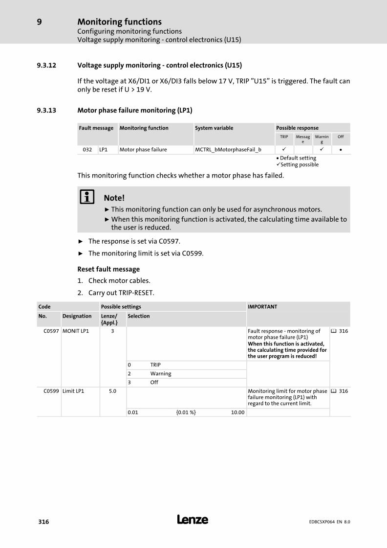
Monitoring functionsConfiguring monitoring functionsVoltage supply monitoring − control electronics (U15)
9
� 316 EDBCSXP064 EN 8.0
9.3.12 Voltage supply monitoring − control electronics (U15)
If the voltage at X6/DI1 or X6/DI3 falls below 17 V, TRIP "U15" is triggered. The fault canonly be reset if U > 19 V.
9.3.13 Motor phase failure monitoring (LP1)
Fault message Monitoring function System variable Possible response
TRIP Message
Warning
Off
032 LP1 Motor phase failure MCTRL_bMotorphaseFail_b � � �
� Default setting�Setting possible
This monitoring function checks whether a motor phase has failed.
� Note!
ƒ This monitoring function can only be used for asynchronous motors.
ƒ When this monitoring function is activated, the calculating time available tothe user is reduced.
ƒ The response is set via C0597.
ƒ The monitoring limit is set via C0599.
Reset fault message
1. Check motor cables.
2. Carry out TRIP−RESET.
Code Possible settings IMPORTANT
No. Designation Lenze/{Appl.}
Selection
C0597 MONIT LP1 3 Fault response − monitoring ofmotor phase failure (LP1)When this function is activated,the calculating time provided forthe user program is reduced!
� 316
0 TRIP
2 Warning
3 Off
C0599 Limit LP1 5.0 Monitoring limit for motor phasefailure monitoring (LP1) withregard to the current limit.
� 316
0.01 {0.01 %} 10.00

Monitoring functionsConfiguring monitoring functions
Monitoring of the resolver cable (Sd2)
9
� 317EDBCSXP064 EN 8.0
9.3.14 Monitoring of the resolver cable (Sd2)
Fault message Monitoring function System variable Possible response
TRIP Message
Warning
Off
082 Sd2 Resolver error MCTRL_bResolverFault_b � � �
� Default setting�Setting possible
This monitoring function monitors the resolver cable and the resolver with regard to opencircuit and protects the motor.
� Stop!
If monitoring is disconnected, the machine can achieve very high speeds incase of faults (e.� g. system cable is disconnected or not correctly screwed),which can result in the damage of the motor and of the driven machine! Thesame applies if "warning" is set as a response.
ƒ For commissioning C0586, always use the Lenze setting (TRIP).
ƒ Only use the possibility of disconnection via C0586 if the monitoring isactivated without apparent reason (e. g. by very long cables or intenseinterference injection of other drives).
ƒ Configure C0586 = 2 (warning) only on the above−mentioned condition,because the pulses are enabled despite faulty feedback.
If a fault with regard to the actual value acquisition is available, it is notdefinitely ensured that monitoring is triggered by overspeed (NMAX, � 322).
This monitoring ...
ƒ is automatically activated if a resolver is selected as an actual speed value encodervia C0419.
ƒ is automatically activated if another actual speed value encoder is selected.
The response is set via C0586.
Code Possible settings IMPORTANT
No. Designation Lenze/{Appl.}
Selection
C0586 MONIT SD2 0 Fault response − monitoringResolver "ResolverFault" (Sd2)
� 317
0 TRIP
2 Warning
3 Off

Monitoring functionsConfiguring monitoring functionsMotor temperature sensor monitoring (Sd6)
9
� 318 EDBCSXP064 EN 8.0
9.3.15 Motor temperature sensor monitoring (Sd6)
Fault message Monitoring function System variable Possible response
TRIP Message
Warning
Off
086 Sd6 Motor temperature sensorfault
MCTRL_bSensorFault_b � � �
� Default setting�Setting possible
This monitoring function checks whether the motor temperature sensor supplies valueswithin the measuring range of −50 ... +250 °C. If the values are outside this measuringrange, monitoring is activated.
The response is set via C0594.
Code Possible settings IMPORTANT
No. Designation Lenze/{Appl.}
Selection
C0594 MONIT SD6 3 Fault response − monitoringKTY sensor for the motortemperature."SensorFault" (Sd6)
� 318
0 TRIP
2 Warning
3 Off

Monitoring functionsConfiguring monitoring functions
Monitoring of the absolute value encoder initialisation (Sd7)
9
� 319EDBCSXP064 EN 8.0
9.3.16 Monitoring of the absolute value encoder initialisation (Sd7)
Fault message Monitoring function System variable Possible response
TRIP Message
Warning
Off
087 Sd7 Absolute value encoderinitialisation error
MCTRL_bEncoderFault_b �
� Default setting�Setting possible
When the ECSxP... axis module is switched on, this monitoring function repeatedlydownloads the absolute value of the hiperface absolute value encoder to identify whetherthe same value is transferred to the drive.
The absolute value encoders (single−turn, multi−turn) are supported by a hiperfaceinterface with various numbers of increments, e.g.: SRM50 with 1024 Sin/Cos periods/rev.or SKM38 with 128 periods/rev.(see also C0419).
If a deviation > 5° on the motor shaft is detected, the monitoring (TRIP) is actuated.
The fault message "Sd7" can only be reset by mains switching!
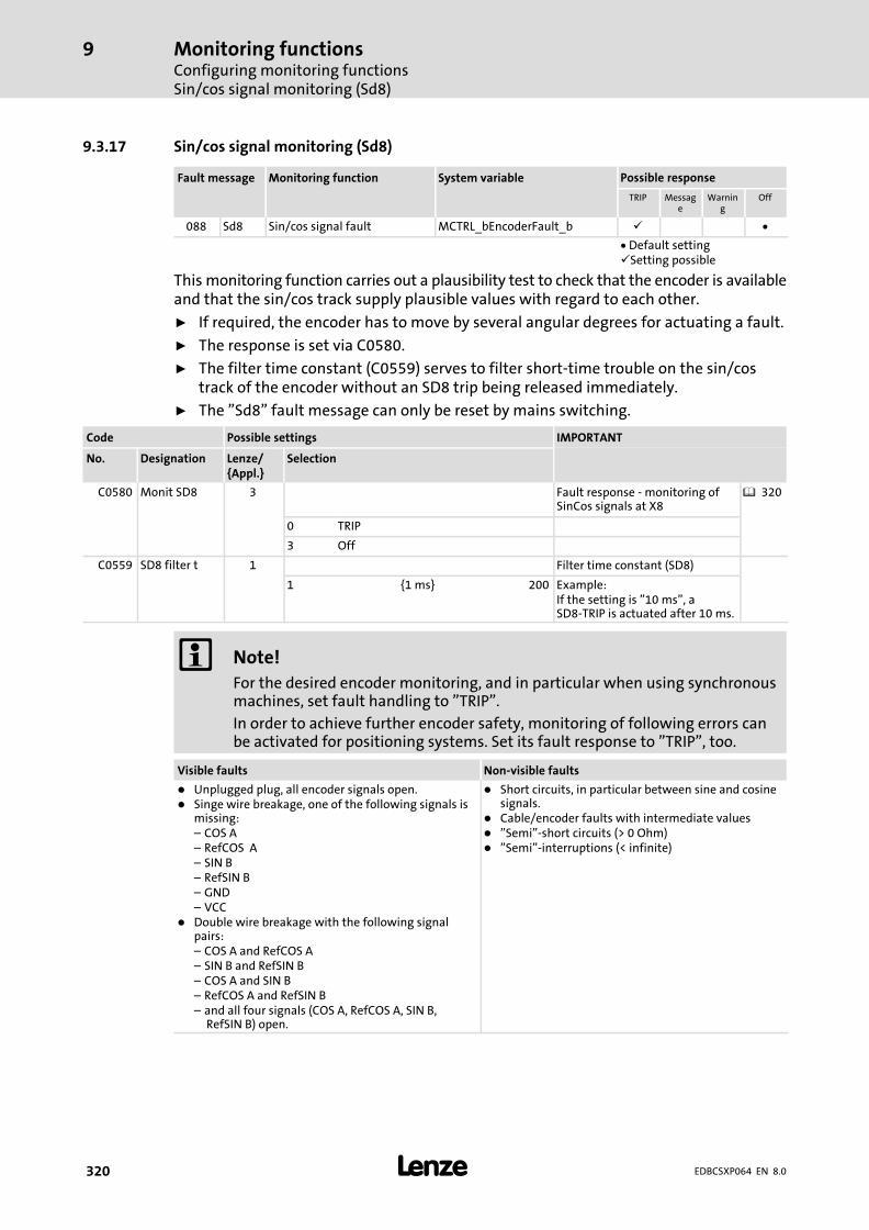
Monitoring functionsConfiguring monitoring functionsSin/cos signal monitoring (Sd8)
9
� 320 EDBCSXP064 EN 8.0
9.3.17 Sin/cos signal monitoring (Sd8)
Fault message Monitoring function System variable Possible response
TRIP Message
Warning
Off
088 Sd8 Sin/cos signal fault MCTRL_bEncoderFault_b � �
� Default setting�Setting possible
This monitoring function carries out a plausibility test to check that the encoder is availableand that the sin/cos track supply plausible values with regard to each other.
ƒ If required, the encoder has to move by several angular degrees for actuating a fault.
ƒ The response is set via C0580.
ƒ The filter time constant (C0559) serves to filter short−time trouble on the sin/costrack of the encoder without an SD8 trip being released immediately.
ƒ The "Sd8" fault message can only be reset by mains switching.
Code Possible settings IMPORTANT
No. Designation Lenze/{Appl.}
Selection
C0580 Monit SD8 3 Fault response − monitoring ofSinCos signals at X8
� 320
0 TRIP
3 Off
C0559 SD8 filter t 1 Filter time constant (SD8)
1 {1 ms} 200 Example:If the setting is "10 ms", aSD8−TRIP is actuated after 10 ms.
� Note!
For the desired encoder monitoring, and in particular when using synchronousmachines, set fault handling to "TRIP".
In order to achieve further encoder safety, monitoring of following errors canbe activated for positioning systems. Set its fault response to "TRIP", too.
Visible faults Non−visible faults
� Unplugged plug, all encoder signals open.� Singe wire breakage, one of the following signals is
missing:– COS A– RefCOS A– SIN B– RefSIN B– GND– VCC
� Double wire breakage with the following signalpairs:– COS A and RefCOS A– SIN B and RefSIN B– COS A and SIN B– RefCOS A and RefSIN B– and all four signals (COS A, RefCOS A, SIN B,
RefSIN B) open.
� Short circuits, in particular between sine and cosinesignals.
� Cable/encoder faults with intermediate values� "Semi"−short circuits (> 0 Ohm)� "Semi"−interruptions (< infinite)
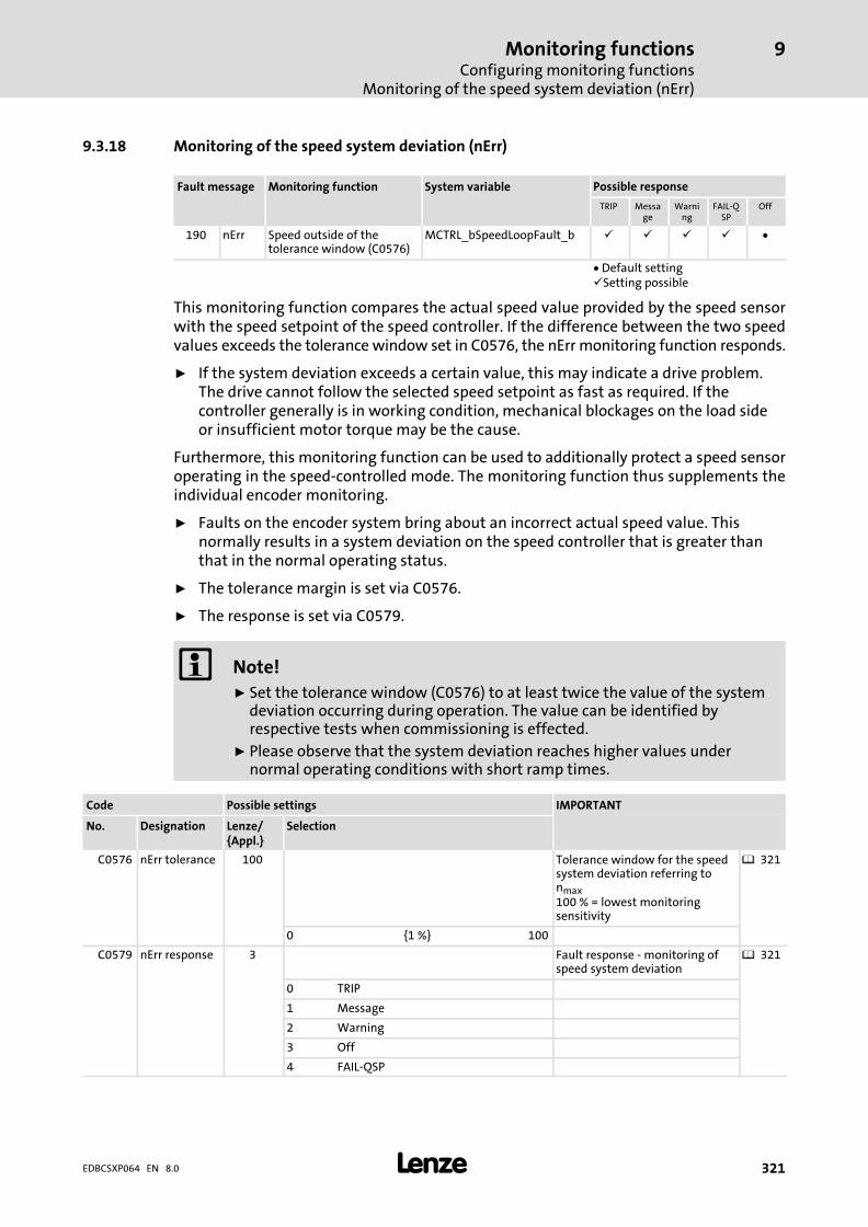
Monitoring functionsConfiguring monitoring functions
Monitoring of the speed system deviation (nErr)
9
� 321EDBCSXP064 EN 8.0
9.3.18 Monitoring of the speed system deviation (nErr)
Fault message Monitoring function System variable Possible response
TRIP Message
Warning
FAIL−QSP
Off
190 nErr Speed outside of thetolerance window (C0576)
MCTRL_bSpeedLoopFault_b � � � � �
� Default setting�Setting possible
This monitoring function compares the actual speed value provided by the speed sensorwith the speed setpoint of the speed controller. If the difference between the two speedvalues exceeds the tolerance window set in C0576, the nErr monitoring function responds.
ƒ If the system deviation exceeds a certain value, this may indicate a drive problem.The drive cannot follow the selected speed setpoint as fast as required. If thecontroller generally is in working condition, mechanical blockages on the load sideor insufficient motor torque may be the cause.
Furthermore, this monitoring function can be used to additionally protect a speed sensoroperating in the speed−controlled mode. The monitoring function thus supplements theindividual encoder monitoring.
ƒ Faults on the encoder system bring about an incorrect actual speed value. Thisnormally results in a system deviation on the speed controller that is greater thanthat in the normal operating status.
ƒ The tolerance margin is set via C0576.
ƒ The response is set via C0579.
� Note!
ƒ Set the tolerance window (C0576) to at least twice the value of the systemdeviation occurring during operation. The value can be identified byrespective tests when commissioning is effected.
ƒ Please observe that the system deviation reaches higher values undernormal operating conditions with short ramp times.
Code Possible settings IMPORTANT
No. Designation Lenze/{Appl.}
Selection
C0576 nErr tolerance 100 Tolerance window for the speedsystem deviation referring tonmax100 % = lowest monitoringsensitivity
� 321
0 {1 %} 100
C0579 nErr response 3 Fault response − monitoring ofspeed system deviation
� 321
0 TRIP
1 Message
2 Warning
3 Off
4 FAIL−QSP

Monitoring functionsConfiguring monitoring functionsMonitoring of max. system speed (NMAX)
9
� 322 EDBCSXP064 EN 8.0
9.3.19 Monitoring of max. system speed (NMAX)
Fault message Monitoring function System variable Possible response
TRIP Message
Warning
Off
200 NMAX Max. system speed exceeded MCTRL_bNmaxFault_b �
� Default setting�Setting possible
The monitoring function responds if the current speed exceeds the max. system speed ortwice the value of C0011 (nmax).
� Stop!
ƒ With regard to active loads (e. g. hoists), pay attention to the fact that thedrive in this case operates without torque. Specific on−site measures arerequired!
ƒ If the actual speed value encoder fails, it is not provided that this monitoringwill be activated.
The max. system speed can be set via C0596.
Code Possible settings IMPORTANT
No. Designation Lenze/{Appl.}
Selection
C0596 NMAX limit 5500 Maximum system speed � 322
0 {1 rpm} 16000
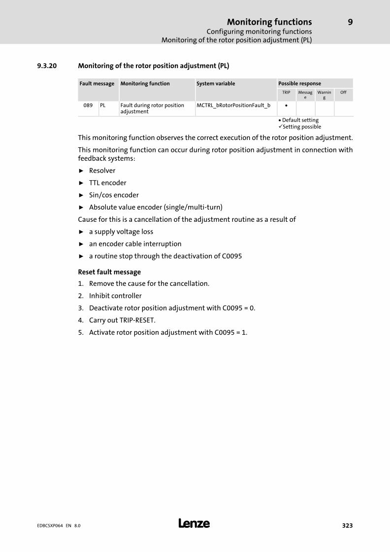
Monitoring functionsConfiguring monitoring functions
Monitoring of the rotor position adjustment (PL)
9
� 323EDBCSXP064 EN 8.0
9.3.20 Monitoring of the rotor position adjustment (PL)
Fault message Monitoring function System variable Possible response
TRIP Message
Warning
Off
089 PL Fault during rotor positionadjustment
MCTRL_bRotorPositionFault_b �
� Default setting�Setting possible
This monitoring function observes the correct execution of the rotor position adjustment.
This monitoring function can occur during rotor position adjustment in connection withfeedback systems:
ƒ Resolver
ƒ TTL encoder
ƒ Sin/cos encoder
ƒ Absolute value encoder (single/multi−turn)
Cause for this is a cancellation of the adjustment routine as a result of
ƒ a supply voltage loss
ƒ an encoder cable interruption
ƒ a routine stop through the deactivation of C0095
Reset fault message
1. Remove the cause for the cancellation.
2. Inhibit controller
3. Deactivate rotor position adjustment with C0095 = 0.
4. Carry out TRIP−RESET.
5. Activate rotor position adjustment with C0095 = 1.

DiagnosticsDiagnostics with Global Drive Control (GDC)
10
� 324 EDBCSXP064 EN 8.0
10 Diagnostics
10.1 Diagnostics with Global Drive Control (GDC)
The GDC diagnostics parameter menu contains the codes for diagnosing the drive system.
ECSXA460
Fig. 10−1 GDC view: Diagnostics − Device − current status
The table in the GDC parameter menu under Diagnostics � Positioning − actual valuesshows the most important operating values:
ECSXA461
Fig. 10−2 GDC view: Positioning diagnostics − actual values

DiagnosticsDiagnostics with Global Drive Control (GDC)
10
� 325EDBCSXP064 EN 8.0
Information on the fault history are displayed under Diagnostics � Faults:
ECSXA462
Fig. 10−3 GDC view: Fault diagnostics
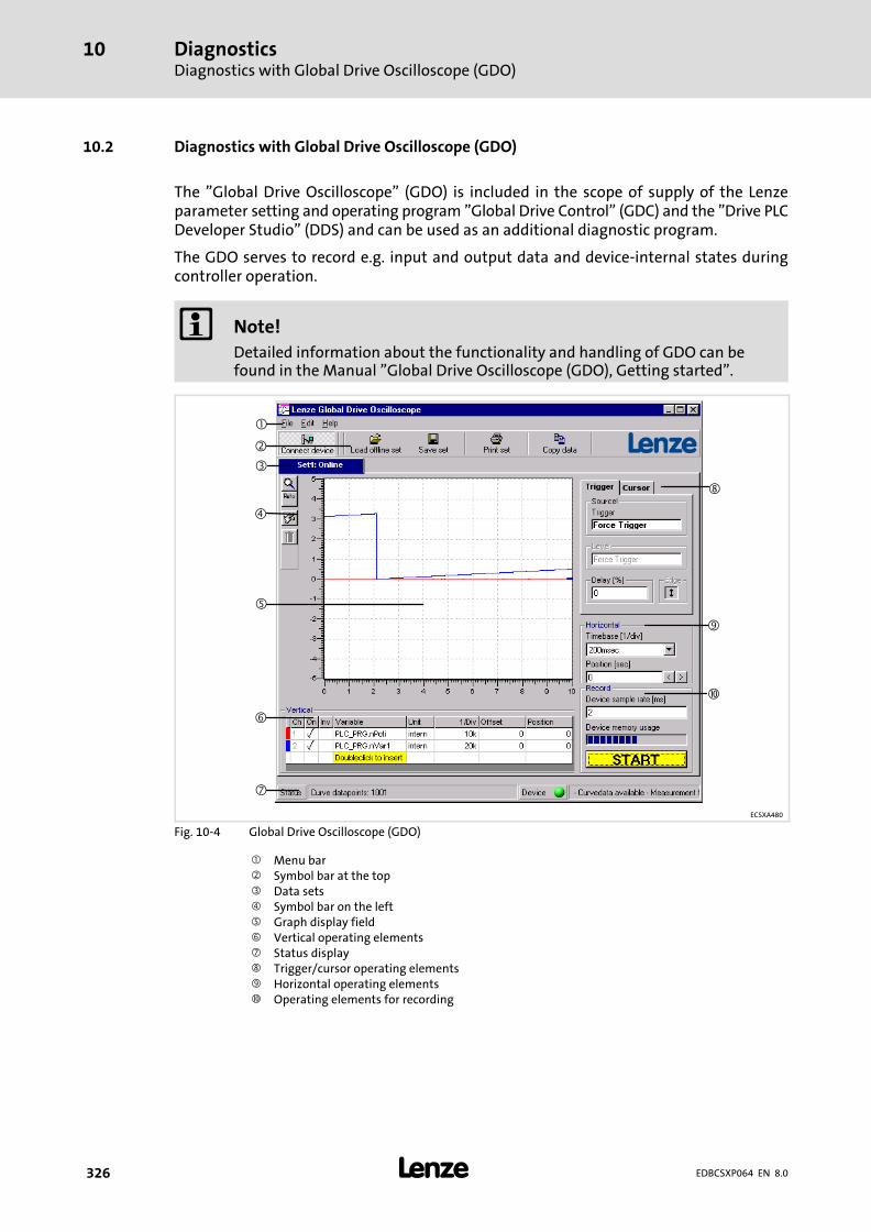
DiagnosticsDiagnostics with Global Drive Oscilloscope (GDO)
10
� 326 EDBCSXP064 EN 8.0
10.2 Diagnostics with Global Drive Oscilloscope (GDO)
The "Global Drive Oscilloscope" (GDO) is included in the scope of supply of the Lenzeparameter setting and operating program "Global Drive Control" (GDC) and the "Drive PLCDeveloper Studio" (DDS) and can be used as an additional diagnostic program.
The GDO serves to record e.g. input and output data and device−internal states duringcontroller operation.
� Note!
Detailed information about the functionality and handling of GDO can befound in the Manual "Global Drive Oscilloscope (GDO), Getting started".
�
�
�
�
�
�
�
�
�
ECSXA480
Fig. 10−4 Global Drive Oscilloscope (GDO)
� Menu bar� Symbol bar at the top� Data sets� Symbol bar on the left Graph display field� Vertical operating elements� Status display� Trigger/cursor operating elements� Horizontal operating elements� Operating elements for recording

DiagnosticsDiagnostics with Global Drive Oscilloscope (GDO)
GDO buttons
10
� 327EDBCSXP064 EN 8.0
10.2.1 GDO buttons
Clicking on the corresponding button executes the respective function.
Press the <F1> key to call the HTML online help.
Symbol bar at the top (�, Fig. 10−4)
Symbol(button)
Function
Connect deviceHere a connection can be established to an attached module.This button has the same function as the menu command File ��Connect.
Load offline setHere saved data sets can be loaded.
Save setHere recorded curves can be saved.This button has the same function as the menu command File ��Save.
Print setHere the recorded curve can be printed in different variants.
Copy dataHere data sets can be copied.This button has the same function as the menu command Edit ��Copy.
Symbol bar on the left (�, Fig. 10−4)
Symbol(button)
Function
ZoomHere different zoom functions can be executed.
Automatic scalingHere all selected curves can be automatically scaled and repositioned and the offset value can be set to"0".The following data types are supported in automatic scaling: BYTE; WORD; DWORD; USINT; UINT;UDINT; SINT; INT; SDINT; Array; Struct
CommentHere information concerning the current data set can be entered. This information is saved togetherwith the current data set and after loading it is displayed as a short info.
DeleteHere the selected offline data set can be deleted.

DiagnosticsDiagnostics with Global Drive Oscilloscope (GDO)Diagnostics with GDO
10
� 328 EDBCSXP064 EN 8.0
10.2.2 Diagnostics with GDO
1. Connect controller via terminal X4 (CAN) or X14 (CAN−AUX) with PC system busadapter to PC/laptop.
2. Supply controller with a control voltage of 24 V (� 64).
3. Start the GDO on the PC/Laptop.
4. Press the button Connect device.
– The dialog "Select device" opens (Fig. 10−5).
– The devices connected to the bus are listed under "Online".
ECSXA481
Fig. 10−5 GDO view: dialog "Select device"
5. Select the corresponding device under Online and click on the OK button.
– The dialog "Select DDS project symbol file" opens:
ECSXA482
Fig. 10−6 GDO view: dialog "Select DDS project symbol file"
6. Select symbol file ECSPOS_Axxx.SDB (xxx = version number) and press button OK .

DiagnosticsDiagnostics with Global Drive Oscilloscope (GDO)
Diagnostics with GDO
10
� 329EDBCSXP064 EN 8.0
7. Select the file ECSPos_ModCycle.los in the menu list under File � Open Online Setand press the button OK.
ECSXA483
Fig. 10−7 GDO view: dialog "File open (*.los)"
8. Press Start button.
9. Position the drive (� 123).
– The profile mode C3095 = 251 enables simple cyclic positioning of the drive.
ECSXA484
Fig. 10−8 GDO view: performing a positioning process
10. Double−click on the last line of the "Variable" column to delete variables from oradd variables to the list.
– The graph display field can display up to eight channels.

DiagnosticsDiagnostics with Global Drive Oscilloscope (GDO)Diagnostics with GDO
10
� 330 EDBCSXP064 EN 8.0
System variables
The meaning of the most important variables is shown in the following table:
Variabledesignation
Data type Signaltype
DisplayCode
Displayformat
Description
g_MCTRL_nNSet_a
integer analog
C0906/1 dec [%] Speed setpoint
g_MCTRL_nNSetIn_a C0050 dec [%]Speed setpoint� in % of nmax (C0011)
g_MCTRL_nNAct_v integer velocity − − Actual speed value [rpm]
g_MCTRL_nNAct_a
integer analog
− −Actual speed value� in % of nmax (C0011)
g_MCTRL_nMSetIn_a C0056 dec [%]Torque setpoint� in % of Mmax (C0057)
g_MCTRL_nMAct_a − −Actual torque� in % of Mmax (C0057)
g_MCTRL_nIAct_a− −
Current motor current� 16384 = 100 %Imax (C0022)
g_MCTRL_nDCVolt_a DC bus voltage: 100 % = 1000 V
g_MCTRL_nPos_a − −Rotor position within onerevolution as analog signal� 90° = 100 % = 16384 inc
g_MCTRL_dnPos_p
doubleinteger
position
− − Actual position
g_MCTRL_dnPosSet_p C0908 dec [inc]Deviation of setpoint angle andactual angle for angle controllers(current following error)
g_bDigin_bCInh_bBool binary − −
Controller inhibit ˘ directly affectscontrol(DCTR)
g_bC1... − − − − Control bit (� 158)
g_bS1... − − − − Status bit (� 161)
g_nMWStatWord1
Word −− − −
Status word 1 from the drive
g_nMWStatWord2 Status word 2 from the drive
g_nMW_txPar1 Word 3 (bytes 5+6) from the drive
g_nMW_txPar2 Word 4 (bytes 7+8) from the drive
g_dnMD_txPAr12Double word 2 (bytes 5+6) fromthe drive
g_wMW_CtrlWord Control word to the drive
g_nMW_RxPar1 Word 2 (bytes 3+4) to the drive
g_nMW_RxPar2 Word 3 (bytes 5+6) to the drive
g_nMW_RxPar3 Word 4 (bytes 7+8) to the drive
g_dnMD_RxPar2Double word 2 (bytes 5 ... 8) to thedrive
DCTRL_wCAN1Ctrl CAN control word
DCTRL_wAIF1Ctrl Word −− − − AIF control word
g_DCTRL_bCInh1_b
Bool binary
C0878/1
bin
Controller inhibitg_DCTRL_bCInh2_b C0878/2
g_DCTRL_bTripSet_b C0878/3 TRIP SET
g_DCTRL_bTripReset_b C0878/4 TRIP RESET
g_DCTRL_bFail_b TRUE = fault active
g_DCTRL_bImp_bTRUE = high−resistance poweroutput stage
g_DCTRL_bTrip_b TRUE = fault active
g_DCTRL_bQspIn_b TRUE = quick stop (QSP)
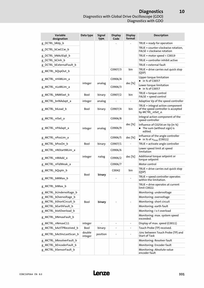
DiagnosticsDiagnostics with Global Drive Oscilloscope (GDO)
Diagnostics with GDO
10
� 331EDBCSXP064 EN 8.0
DescriptionDisplayformat
DisplayCode
Signaltype
Data typeVariabledesignation
g_DCTRL_bRdy_b
y
− − TRUE = ready for operation
g_DCTRL_bCwCCw_bTRUE = counter−clockwise rotation,FALSE = clockwise rotation
g_DCTRL_bNActEq0_b TRUE = motor speed < C0019
g_DCTRL_bCInh_b TRUE = controller inhibit active
g_DCTRL_bExternalFault_b TRUE = external fault
g_MCTRL_bQspOut_bC0907/3 bin TRUE = drive carries out quick stop
(QSP)
g_MCTRL_nHiMLim_a
integer analog
C0906/4
dec [%]
Upper torque limitation� in % of C0057
g_MCTRL_nLoMLim_a C0906/3Lower torque limitation� in % of C0057
g_MCTRL_bNMSwt_b Bool binary C0907/2 binTRUE = torque controlFALSE = speed control
g_MCTRL_bnNAdapt_a integer analog − − Adaptive Vp of the speed controller
g_MCTRL_bILoad_b Bool binary C0907/4 binTRUE = integral action componentof the speed controller is acceptedby MCTRL_nISet_a.
g_MCTRL_nISet_a
integer analog
C0906/8
dec [%]
Integral action component of thespeed controller
g_MCTRL_nPAdapt_a C0906/9Influence of C0254 on Vp (in %)� The sum (without sign) is
edited.
g_MCTRL_nPosLim_a C0906/5 dec [%]Influence of the angle controller� in % of nmax (C0011)
g_MCTRL_bPosOn_b Bool binary C0907/1 − TRUE = activate angle controller
g_MCTRL_nNStartMLim_a
integer nalog
C0906/6
dec [%]
Lower speed limit at speedlimitation
g_MCTRL_nMAdd_a C0906/2Additional torque setpoint ortorque setpoint
g_MCTRL_nFldWeak_a C0906/7 Motor control
g_MCTRL_bQspIn_b
Bool binarybinary
C0042 binTRUE = drive carries out quick stop(QSP)
g_MCTRL_bMMax_b − −TRUE = speed controller operateswithin the limitation.
g_MCTRL_bIMax_b
Bool binarybinary − −
TRUE = drive operates at currentlimit C0022.
g_MCTRL_bUndervoltage_b Monitoring: undervoltage
g_MCTRL_bOvervoltage_b Monitoring: overvoltage
g_MCTRL_bShortCircuit_b Monitoring: short circuit
g_MCTRL_bEarthFault_b Monitoring: earth fault
g_MCTRL_bIxtOverload_b Monitoring: I x t overload
g_MCTRL_bNmaxFault_bMonitoring: max. system speedexceeded.
g_MCTRL_nNmaxC11 integer − − − Display of max. speed (C0011)
g_MCTRL_bActTPReceived_b Bool binary − − Touch Probe (TP) received.
g_MCTRL_bActIncLastScan_bdoubleinteger
position − −�inc between Touch Probe (TP) andStart of Task
g_MCTRL_bResolverFault_b Monitoring: Resolver fault
g_MCTRL_bEncoderFault_b Monitoring: Encoder fault
g_MCTRL_bSensorFault_b Monitoring: Absolute valueencoder fault
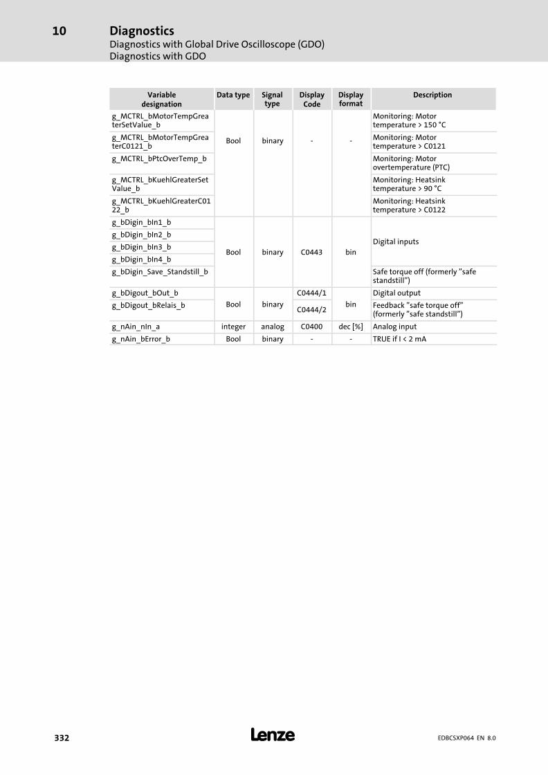
DiagnosticsDiagnostics with Global Drive Oscilloscope (GDO)Diagnostics with GDO
10
� 332 EDBCSXP064 EN 8.0
DescriptionDisplayformat
DisplayCode
Signaltype
Data typeVariabledesignation
g_MCTRL_bMotorTempGreaterSetValue_b
Bool binary − −
Monitoring: Motortemperature > 150 °C
g_MCTRL_bMotorTempGreaterC0121_b
Monitoring: Motortemperature > C0121
g_MCTRL_bPtcOverTemp_b Monitoring: Motorovertemperature (PTC)
g_MCTRL_bKuehlGreaterSetValue_b
Monitoring: Heatsinktemperature > 90 °C
g_MCTRL_bKuehlGreaterC0122_b
Monitoring: Heatsinktemperature > C0122
g_bDigin_bIn1_b
Bool binary C0443 bin
Digital inputsg_bDigin_bIn2_b
g_bDigin_bIn3_b
g_bDigin_bIn4_b
g_bDigin_Save_Standstill_b Safe torque off (formerly "safestandstill")
g_bDigout_bOut_b
Bool binary
C0444/1
bin
Digital output
g_bDigout_bRelais_bC0444/2
Feedback "safe torque off"(formerly "safe standstill")
g_nAin_nIn_a integer analog C0400 dec [%] Analog input
g_nAin_bError_b Bool binary − − TRUE if I < 2 mA
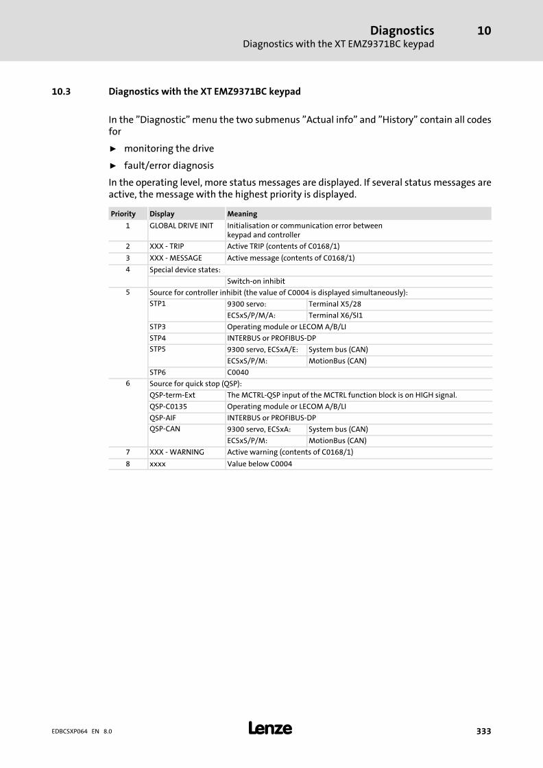
DiagnosticsDiagnostics with the XT EMZ9371BC keypad
10
� 333EDBCSXP064 EN 8.0
10.3 Diagnostics with the XT EMZ9371BC keypad
In the "Diagnostic" menu the two submenus "Actual info" and "History" contain all codesfor
ƒ monitoring the drive
ƒ fault/error diagnosis
In the operating level, more status messages are displayed. If several status messages areactive, the message with the highest priority is displayed.
Priority Display Meaning
1 GLOBAL DRIVE INIT Initialisation or communication error betweenkeypad and controller
2 XXX − TRIP Active TRIP (contents of C0168/1)
3 XXX − MESSAGE Active message (contents of C0168/1)
4 Special device states:
Switch−on inhibit
5 Source for controller inhibit (the value of C0004 is displayed simultaneously):
STP1 9300 servo: Terminal X5/28
ECSxS/P/M/A: Terminal X6/SI1
STP3 Operating module or LECOM A/B/LI
STP4 INTERBUS or PROFIBUS−DP
STP5 9300 servo, ECSxA/E: System bus (CAN)
ECSxS/P/M: MotionBus (CAN)
STP6 C0040
6 Source for quick stop (QSP):
QSP−term−Ext The MCTRL−QSP input of the MCTRL function block is on HIGH signal.
QSP−C0135 Operating module or LECOM A/B/LI
QSP−AIF INTERBUS or PROFIBUS−DP
QSP−CAN 9300 servo, ECSxA: System bus (CAN)
ECSxS/P/M: MotionBus (CAN)
7 XXX − WARNING Active warning (contents of C0168/1)
8 xxxx Value below C0004
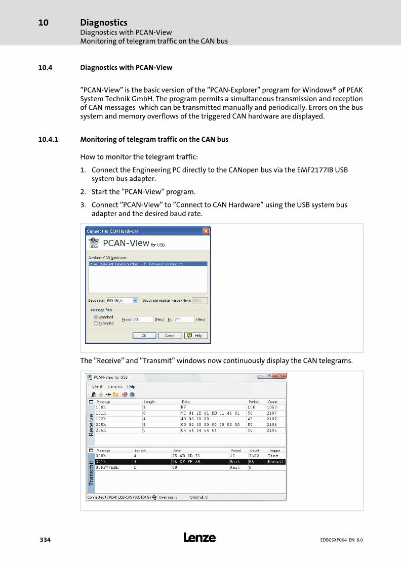
DiagnosticsDiagnostics with PCAN−ViewMonitoring of telegram traffic on the CAN bus
10
� 334 EDBCSXP064 EN 8.0
10.4 Diagnostics with PCAN−View
"PCAN−View" is the basic version of the "PCAN−Explorer" program for Windows® of PEAKSystem Technik GmbH. The program permits a simultaneous transmission and receptionof CAN messages which can be transmitted manually and periodically. Errors on the bussystem and memory overflows of the triggered CAN hardware are displayed.
10.4.1 Monitoring of telegram traffic on the CAN bus
How to monitor the telegram traffic:
1. Connect the Engineering PC directly to the CANopen bus via the EMF2177IB USBsystem bus adapter.
2. Start the "PCAN−View" program.
3. Connect "PCAN−View" to "Connect to CAN Hardware" using the USB system busadapter and the desired baud rate.
The "Receive" and "Transmit" windows now continuously display the CAN telegrams.
DiagnosticsDiagnostics with PCAN−View
Monitoring of telegram traffic on the CAN bus
10
� 335EDBCSXP064 EN 8.0
On the basis of the IDs displayed, you can assign the telegrams to the devices.
If no telegrams are displayed, this may be caused by various factors:
ƒ Is your Engineering PC connected to the correct CAN bus?
ƒ Is the correct system bus adapter activated under "System control, CAN Hardware"?
ƒ What does the status line of the »PCAN−View« contain?
In case of "Bus Heavy" mostly a node with a wrong baud rate disturbs the bus traffic.
ƒ Do the devices are in the "Operational" status?

DiagnosticsDiagnostics with PCAN−ViewSetting all CAN nodes to the "Operational" status
10
� 336 EDBCSXP064 EN 8.0
10.4.2 Setting all CAN nodes to the "Operational" status
How to set all CAN nodes to the "Operational" status:
1. Create the following CAN message under "New transmit message":
2. Select the CAN message in the "Transmit" window and press the <space bar> onceto transmit the CAN message.
Troubleshooting and fault eliminationFault analysis
Fault analysis via the LED display
11
� 337EDBCSXP064 EN 8.0
11 Troubleshooting and fault elimination
Failures can be quickly detected and classified by means of display elements or statusmessages via the MotionBus (CAN).
Display elements and status messages provide a rough classification of the trouble.
The chapter "11.3 Fault messages" ( 343)contains notes on causes and deletion offaults.
11.1 Fault analysis
11.1.1 Fault analysis via the LED display
LED Operating state Check
Red Green
Off On Controller enabled, no fault
Off Blinking Controller inhibit (CINH) active, switch−on inhibit C0183
Blinking Off Trouble/fault (TRIP) is active C0168/1
Blinking On Warning/FAIL−QSP is active C0168/1
11.1.2 Fault analysis with keypad XT EMZ9371BC
The status messages in the display indicate the controller status.
Display Controller status Check
RDY Controller ready for operation, controller can be inhibited. C0183, C0168/1
IMP Pulses at the power stage inhibited. C0183, C0168/1
Imax Maximum current reached.
Mmax Maximum torque reached.
FAIL Fault through TRIP, message, fail QSP or warning. C0183, C0168/1

Troubleshooting and fault eliminationFault analysisFault analysis with the history buffer
11
� 338 EDBCSXP064 EN 8.0
11.1.3 Fault analysis with the history buffer
The history buffer enables you to retrace faults. Fault messages are stored in the fivememory locations in the order of their occurrence. The memory locations can be retrievedvia codes C4168/1...5 and C4169/1...5.
Structure of the history buffer
ƒ C4168/1...5 displays the five fault messages occurred last.
ƒ C4169/1...5 displays the corresponding time based on the elapsed hour meterC0178.
ƒ The fields under "Current fault" show information about the active fault message.
ƒ If the fault message is no longer active or has been reset:
– the contents of the memory locations 1 ... 5 are stored in a "higher" location.
– the contents of the memory location 5 are eliminated from the history buffer andcannot be called any longer.
– memory location 1 is deleted (no active fault).
ƒ The history buffer contains the following information on every fault messageoccurred:
– Fault message number and response
– Time of the last occurrence
� Note!
If several fault messages with different responses occur at the same time, onlythe fault message the response of which has the highest priority is enteredinto the history buffer.
ƒ TRIP (highest) → Message → FAIL−QSP → Warning (lowest)

Troubleshooting and fault eliminationFault analysis
Fault analysis with the history buffer
11
� 339EDBCSXP064 EN 8.0
Assignment of information to the codes
Codes and retrievable information Information on ...
C4168 C4169 Subcode
Number and response of thefault message
Time of the last occurrence
1 Active fault message
2 Last fault message
3 Last but one fault message
4 Last but two fault message
5 Last but three fault message
Deleting entries in the history buffer
The entries in the history buffer can be deleted with C4167 = 1.
ƒ This function only works when no trouble is active.
Code Possible settings IMPORTANT
No. Designation Lenze/{Appl.}
Selection
C4166 TripAppReset 0 Application fault message reset. � 338
0 Fault message active
1 Reset fault message
Fault message reset
The current fault message can be reset with C4166 = 1.
Code Possible settings IMPORTANT
No. Designation Lenze/{Appl.}
Selection
C4167 AppHistReset 0 Deleting application faultmessage history buffer.
� 338
0 No reaction
1 Delete history buffer
Troubleshooting and fault eliminationFault analysisFault analysis via LECOM status words (C0150/C0155)
11
� 340 EDBCSXP064 EN 8.0
11.1.4 Fault analysis via LECOM status words (C0150/C0155)
The LECOM status words (C0150/C0155) are coded as follows:
Code Possible settings IMPORTANT
No. Designation Lenze/{Appl.}
Selection
C0150 Status word 0 Device status word fornetworking via automationinterface (AIF)Read only
� 163� 340
0 {1} 65535 Controller evaluates informationas 16 bits (binary−coded)
Bit 0 Not assigned
Bit 1 Pulse inhibit (IMP)
Bit2 Not assigned
Bit3 Not assigned
Bit4 Not assigned
Bit5 Not assigned
Bit 6 n = 0
Bit 7 Controller inhibit (CINH)
Bit 8 Device status bit 1
Bit 9 Device status bit 2
Bit10 Device status bit 3
Bit11 Device status bit 4
Bit12 Warning
Bit13 Message
Bit14 Not assigned
Bit15 Not assigned
The status bits 8 ... 11 in C0150 display the binary−coded device status of the axis module:
Status bit 11 Status bit 10 Status bit 9 Status bit 8 Description
0 0 0 0 Initialisation after connecting thesupply voltage
0 0 0 1 Switch−on inhibit / restartprotection active (C0142 = 0)
0 0 1 1 Controller inhibited
0 1 1 0 Controller enabled
0 1 1 1 A monitoring function returns a"message".
1 0 0 0 A monitoring function returns a"TRIP".
1 0 1 0 A monitoring function returns a"FAIL−QSP".
0 = FALSE 1 = TRUE

Troubleshooting and fault eliminationFault analysis
Fault analysis via LECOM status words (C0150/C0155)
11
� 341EDBCSXP064 EN 8.0
Code Possible settings IMPORTANT
No. Designation Lenze/{Appl.}
Selection
C0155 Status word 2 0 Status word 2 (advanced statusword)Display only
0 {1} 65535 Controller interprets informationas 16 bit (binary coded)
Bit 0 Active fault
Bit 1 Mmax reached
Bit 2 Imax reached
Bit 3 Pulse inhibit(IMP)
Bit 4 Ready for operation (RDY)
Bit 5 Controller inhibit (CINH)
Bit 6 TRIP active
Bit 7 Initialisation
Bit 8 Motor direction of rotation (Cw/CCw)
Bit 9 Not assigned
Bit 10 Not assigned
Bit 11 Not assigned
Bit 12 Not assigned
Bit 13 Not assigned
Bit 14 Not assigned
Bit 15 Not assigned
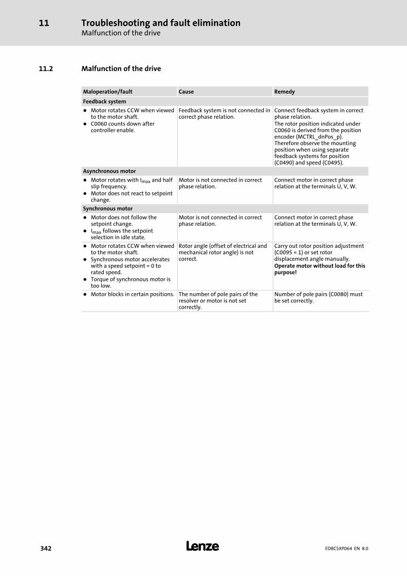
Troubleshooting and fault eliminationMalfunction of the drive
11
� 342 EDBCSXP064 EN 8.0
11.2 Malfunction of the drive
Maloperation/fault Cause Remedy
Feedback system
� Motor rotates CCW when viewedto the motor shaft.
� C0060 counts down aftercontroller enable.
Feedback system is not connected incorrect phase relation.
Connect feedback system in correctphase relation.The rotor position indicated underC0060 is derived from the positionencoder (MCTRL_dnPos_p).Therefore observe the mountingposition when using separatefeedback systems for position(C0490) and speed (C0495).
Asynchronous motor
� Motor rotates with Imax and halfslip frequency.
� Motor does not react to setpointchange.
Motor is not connected in correctphase relation.
Connect motor in correct phaserelation at the terminals U, V, W.
Synchronous motor
� Motor does not follow thesetpoint change.
� Imax follows the setpointselection in idle state.
Motor is not connected in correctphase relation.
Connect motor in correct phaserelation at the terminals U, V, W.
� Motor rotates CCW when viewedto the motor shaft.
� Synchronous motor accelerateswith a speed setpoint = 0 torated speed.
� Torque of synchronous motor istoo low.
Rotor angle (offset of electrical andmechanical rotor angle) is notcorrect.
Carry out rotor position adjustment(C0095 = 1) or set rotordisplacement angle manually.Operate motor without load for thispurpose!
� Motor blocks in certain positions. The number of pole pairs of theresolver or motor is not setcorrectly.
Number of pole pairs (C0080) mustbe set correctly.

Troubleshooting and fault eliminationFault messages
Causes and remedies
11
� 343EDBCSXP064 EN 8.0
11.3 Fault messages
11.3.1 Causes and remedies
� Tip!
When the fault messages are retrieved via the MotionBus/system bus (CAN),the fault messages are displayed as numbers (see column "Fault message ˘No." in the following table).
Fault message Description Cause Remedy
No. Display
−−− −−− No fault − −
0011 OC1 Short circuit of motor cable Short circuit � Search for cause of shortcircuit.
� Check motor cable.
Excessive capacitive chargingcurrent in the motor cable.
Use motor cable which is shorteror of lower capacitance.
0012 OC2 Motor cable earth fault One of the motor phases hasearth contact.
� Search for cause of shortcircuit.
� Check motor cable.
0015 OC5 I x t overload TRIP (axismodule, fix 100 %)
Current overload of the axismodule, e.g. by:� frequent and too long
acceleration processes� continuous overload with
Imotor > 1.05 x INx
Check drive dimensioning.
0016 OC6 I2 x t overload TRIP (motor, C0120) Current overload of the motor,e.g. due to:� frequent or too long
acceleration processes� impermissible continuous
current
� Check drive dimensioning.� Check setting of C0120.
x017 OC7 I x t overload warning (axismodule, C0123)
Current overload of the axismodule > C0123 (e.g. due tofrequent or too long accelerationphases)
� Check drive dimensioning.� Check setting of C0123.
x018 OC8 I2 x t overload warning(motor, C0127)
Current overload of the motor> C0127 (e.g. due to frequent ortoo long acceleration phases)
� Check drive dimensioning.� Check setting of C0127.
1020 OU Overvoltage in DC bus Braking energy is too high.(DC−bus voltage is higher than setin C0173.)
� Use braking unit orregenerative module.
� Check dimensioning of thebrake resistance.
1030 LU Undervoltage in DC bus DC−bus voltage is lower thanspecified under C0174.
� Check mains voltage.� Check power supply module.
x032 LP1 Motor phase failure A current−carrying motor phasehas failed.
� Check motor.� Check motor cable.� Switch off monitoring
(C0597 = 3).
The current limit value is set toolow.
� Set higher current limit valuevia C0599.
x041 AP1 Internal fault Contact Lenze.
x: 0 = TRIP, 1 = Message, 2 = Warning, 3 = FAIL−QSP
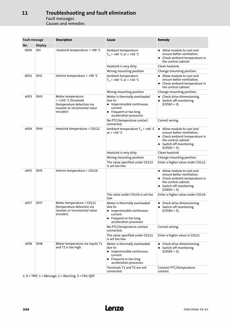
Troubleshooting and fault eliminationFault messagesCauses and remedies
11
� 344 EDBCSXP064 EN 8.0
RemedyCauseDescriptionFault message RemedyCauseDescription
DisplayNo.
0050 OH Heatsink temperature > +90 °C Ambient temperatureTu > +40 °C or > +50 °C
� Allow module to cool andensure better ventilation.
� Check ambient temperature inthe control cabinet.
Heatsink is very dirty. Clean heatsink.
Wrong mounting position Change mounting position.
0051 OH1 Interior temperature > +90 °C Ambient temperatureTu > +40 °C or > +50 °C
� Allow module to cool andensure better ventilation.
� Check ambient temperature inthe control cabinet.
Wrong mounting position Change mounting position.
x053 OH3 Motor temperature> +150 °C threshold(temperature detection viaresolver or incremental valueencoder)
Motor is thermally overloadeddue to:� Impermissible continuous
current� Frequent or too long
acceleration processes
� Check drive dimensioning.� Switch off monitoring
(C0583 = 3).
No PTC/temperature contactconnected.
Correct wiring.
x054 OH4 Heatsink temperature > C0122 Ambient temperature Tu > +40 °Cor > +50 °C
� Allow module to cool andensure better ventilation.
� Check ambient temperature inthe control cabinet.
� Switch off monitoring(C0582 = 3).
Heatsink is very dirty. Clean heatsink
Wrong mounting position Change mounting position.
The value specified under C0122is set too low.
Enter a higher value under C0122.
x055 OH5 Interior temperature > C0124 � Allow module to cool andensure better ventilation.
� Check ambient temperature inthe control cabinet.
� Switch off monitoring(C0605 = 3).
The value under C0124 is set toolow.
Enter a higher value under C0124.
x057 OH7 Motor temperature > C0121(temperature detection viaresolver or incremental valueencoder)
Motor is thermally overloadeddue to:� Impermissible continuous
current� Frequent or too long
acceleration processes
� Check drive dimensioning.� Switch off monitoring
(C0584 = 3).
No PTC/temperature contactconnected.
Correct wiring.
The value specified under C0121is set too low.
Enter a higher value in C0121.
x058 OH8 Motor temperature via inputs T1and T2 is too high.
Motor is thermally overloadeddue to:� Impermissible continuous
current� Frequent or too long
acceleration processes
� Check drive dimensioning.� Switch off monitoring
(C0585 = 3).
Terminals T1 and T2 are notconnected
Connect PTC/temperaturecontact.
x: 0 = TRIP, 1 = Message, 2 = Warning, 3 = FAIL−QSP
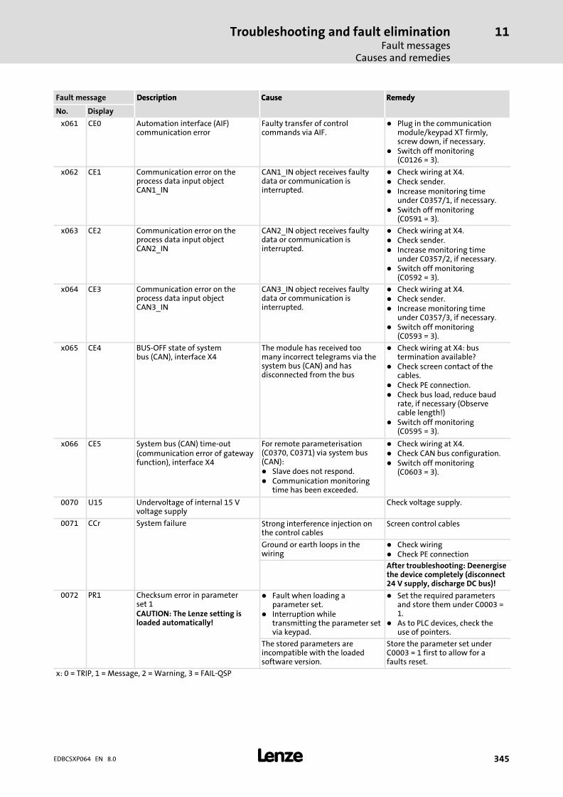
Troubleshooting and fault eliminationFault messages
Causes and remedies
11
� 345EDBCSXP064 EN 8.0
RemedyCauseDescriptionFault message RemedyCauseDescription
DisplayNo.
x061 CE0 Automation interface (AIF)communication error
Faulty transfer of controlcommands via AIF.
� Plug in the communicationmodule/keypad XT firmly,screw down, if necessary.
� Switch off monitoring(C0126 = 3).
x062 CE1 Communication error on theprocess data input objectCAN1_IN
CAN1_IN object receives faultydata or communication isinterrupted.
� Check wiring at X4.� Check sender.� Increase monitoring time
under C0357/1, if necessary.� Switch off monitoring
(C0591 = 3).
x063 CE2 Communication error on theprocess data input objectCAN2_IN
CAN2_IN object receives faultydata or communication isinterrupted.
� Check wiring at X4.� Check sender.� Increase monitoring time
under C0357/2, if necessary.� Switch off monitoring
(C0592 = 3).
x064 CE3 Communication error on theprocess data input objectCAN3_IN
CAN3_IN object receives faultydata or communication isinterrupted.
� Check wiring at X4.� Check sender.� Increase monitoring time
under C0357/3, if necessary.� Switch off monitoring
(C0593 = 3).
x065 CE4 BUS−OFF state of systembus (CAN), interface X4
The module has received toomany incorrect telegrams via thesystem bus (CAN) and hasdisconnected from the bus
� Check wiring at X4: bustermination available?
� Check screen contact of thecables.
� Check PE connection.� Check bus load, reduce baud
rate, if necessary (Observecable length!)
� Switch off monitoring(C0595 = 3).
x066 CE5 System bus (CAN) time−out(communication error of gatewayfunction), interface X4
For remote parameterisation(C0370, C0371) via system bus(CAN):� Slave does not respond.� Communication monitoring
time has been exceeded.
� Check wiring at X4.� Check CAN bus configuration.� Switch off monitoring
(C0603 = 3).
0070 U15 Undervoltage of internal 15 Vvoltage supply
Check voltage supply.
0071 CCr System failure Strong interference injection onthe control cables
Screen control cables
Ground or earth loops in thewiring
� Check wiring� Check PE connection
After troubleshooting: Deenergisethe device completely (disconnect24 V supply, discharge DC bus)!
0072 PR1 Checksum error in parameterset 1CAUTION: The Lenze setting isloaded automatically!
� Fault when loading aparameter set.
� Interruption whiletransmitting the parameter setvia keypad.
� Set the required parametersand store them under C0003 =1.
� As to PLC devices, check theuse of pointers.
The stored parameters areincompatible with the loadedsoftware version.
Store the parameter set underC0003 = 1 first to allow for afaults reset.
x: 0 = TRIP, 1 = Message, 2 = Warning, 3 = FAIL−QSP
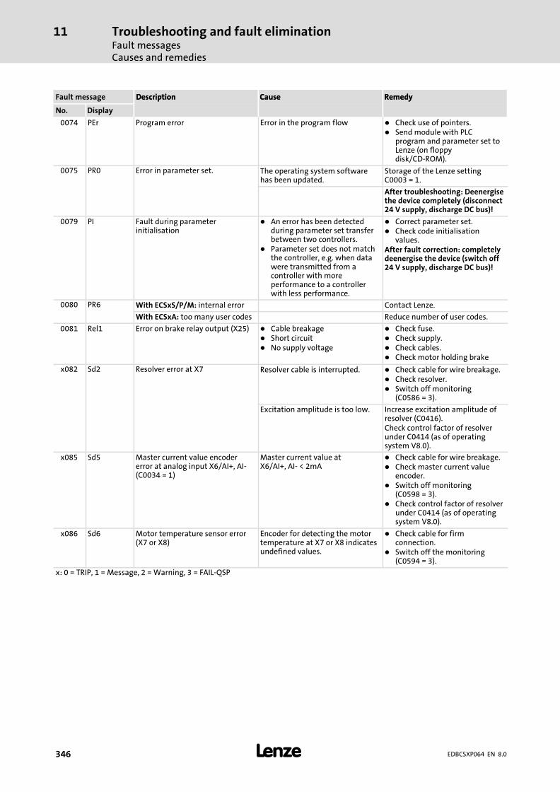
Troubleshooting and fault eliminationFault messagesCauses and remedies
11
� 346 EDBCSXP064 EN 8.0
RemedyCauseDescriptionFault message RemedyCauseDescription
DisplayNo.
0074 PEr Program error Error in the program flow � Check use of pointers.� Send module with PLC
program and parameter set toLenze (on floppydisk/CD−ROM).
0075 PR0 Error in parameter set. The operating system softwarehas been updated.
Storage of the Lenze settingC0003 = 1.
After troubleshooting: Deenergisethe device completely (disconnect24 V supply, discharge DC bus)!
0079 PI Fault during parameterinitialisation
� An error has been detectedduring parameter set transferbetween two controllers.
� Parameter set does not matchthe controller, e.g. when datawere transmitted from acontroller with moreperformance to a controllerwith less performance.
� Correct parameter set.� Check code initialisation
values.After fault correction: completelydeenergise the device (switch off24 V supply, discharge DC bus)!
0080 PR6 With ECSxS/P/M: internal error Contact Lenze.
With ECSxA: too many user codes Reduce number of user codes.
0081 Rel1 Error on brake relay output (X25) � Cable breakage� Short circuit� No supply voltage
� Check fuse.� Check supply.� Check cables.� Check motor holding brake
x082 Sd2 Resolver error at X7 Resolver cable is interrupted. � Check cable for wire breakage.� Check resolver.� Switch off monitoring
(C0586 = 3).
Excitation amplitude is too low. Increase excitation amplitude ofresolver (C0416).Check control factor of resolverunder C0414 (as of operatingsystem V8.0).
x085 Sd5 Master current value encodererror at analog input X6/AI+, AI−(C0034 = 1)
Master current value atX6/AI+, AI− < 2mA
� Check cable for wire breakage.� Check master current value
encoder.� Switch off monitoring
(C0598 = 3).� Check control factor of resolver
under C0414 (as of operatingsystem V8.0).
x086 Sd6 Motor temperature sensor error(X7 or X8)
Encoder for detecting the motortemperature at X7 or X8 indicatesundefined values.
� Check cable for firmconnection.
� Switch off the monitoring(C0594 = 3).
x: 0 = TRIP, 1 = Message, 2 = Warning, 3 = FAIL−QSP
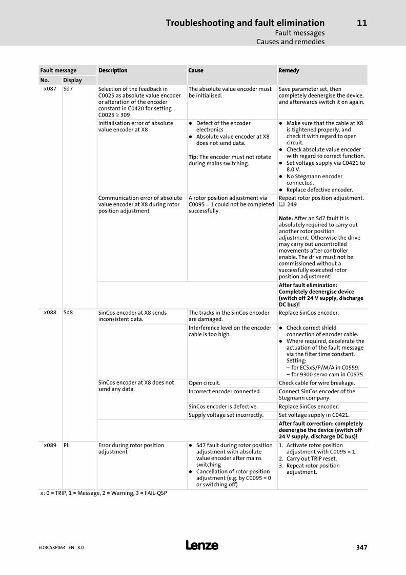
Troubleshooting and fault eliminationFault messages
Causes and remedies
11
� 347EDBCSXP064 EN 8.0
RemedyCauseDescriptionFault message RemedyCauseDescription
DisplayNo.
x087 Sd7 Selection of the feedback inC0025 as absolute value encoderor alteration of the encoderconstant in C0420 for settingC0025 � 309
The absolute value encoder mustbe initialised.
Save parameter set, thencompletely deenergise the device,and afterwards switch it on again.
Initialisation error of absolutevalue encoder at X8
� Defect of the encoderelectronics
� Absolute value encoder at X8does not send data.
Tip: The encoder must not rotateduring mains switching.
� Make sure that the cable at X8is tightened properly, andcheck it with regard to opencircuit.
� Check absolute value encoderwith regard to correct function.
� Set voltage supply via C0421 to8.0 V.
� No Stegmann encoderconnected.
� Replace defective encoder.
Communication error of absolutevalue encoder at X8 during rotorposition adjustment
A rotor position adjustment viaC0095 = 1 could not be completedsuccessfully.
Repeat rotor position adjustment.� 249
Note: After an Sd7 fault it isabsolutely required to carry outanother rotor positionadjustment. Otherwise the drivemay carry out uncontrolledmovements after controllerenable. The drive must not becommissioned without asuccessfully executed rotorposition adjustment!
After fault elimination:Completely deenergise device(switch off 24 V supply, dischargeDC bus)!
x088 Sd8 SinCos encoder at X8 sendsinconsistent data.
The tracks in the SinCos encoderare damaged.
Replace SinCos encoder.
Interference level on the encodercable is too high.
� Check correct shieldconnection of encoder cable.
� Where required, decelerate theactuation of the fault messagevia the filter time constant.Setting:– for ECSxS/P/M/A in C0559.– for 9300 servo cam in C0575.
SinCos encoder at X8 does notsend any data.
Open circuit. Check cable for wire breakage.
Incorrect encoder connected. Connect SinCos encoder of theStegmann company.
SinCos encoder is defective. Replace SinCos encoder.
Supply voltage set incorrectly. Set voltage supply in C0421.
After fault correction: completelydeenergise the device (switch off24 V supply, discharge DC bus)!
x089 PL Error during rotor positionadjustment
� Sd7 fault during rotor positionadjustment with absolutevalue encoder after mainsswitching
� Cancellation of rotor positionadjustment (e.g. by C0095 = 0or switching off)
1. Activate rotor positionadjustment with C0095 = 1.
2. Carry out TRIP reset.3. Repeat rotor position
adjustment.
x: 0 = TRIP, 1 = Message, 2 = Warning, 3 = FAIL−QSP

Troubleshooting and fault eliminationFault messagesCauses and remedies
11
� 348 EDBCSXP064 EN 8.0
RemedyCauseDescriptionFault message RemedyCauseDescription
DisplayNo.
x091 EEr External monitoring has beentriggered via DCTRL.
A digital signal assigned to theTRIP−SET function has beenactivated.
� Check external encoder.� Switch off the monitoring
(C0581 = 3).
x095 FAN1 Fan monitoring(for built−in units)
Heatsink fan is locked, dirty ordefect.
Clean or exchange heatsink fan.
0105 H05 Internal fault (memory) Contact Lenze.
0107 H07 Internal fault (power stage) During initialisation of thecontroller, an incorrect powerstage was detected.
Contact Lenze.
x108 H08 "Extension board" error "Extension board" not connectedcorrectly.
� Connect "extension board"correctly.
� Check connector.
"Extension board" is notsupported by PLC program.
� Adapt PLC program to"extension board".
� Use "extension board" which issupported by PLC program.
x110 H10 Heatsink temperature sensorerror
Sensor for detecting the heatsinktemperature indicates undefinedvalues.
� Contact Lenze.� Switch off the monitoring
(C0588 = 3).
x111 H11 Temperature sensor error:Temperature inside the controller
Sensor for detecting the internaltemperature indicates undefinedvalues.
� Contact Lenze.� Switch off the monitoring
(C0588 = 3).
x122 CE11 Communication error at theprocess data input objectCANaux1_IN
CANaux1_IN object receivesfaulty data or communication isinterrupted.
� Check wiring at X14.� Check transmitter.� Increase monitoring time
under C2457/1, if necessary.� Switch off monitoring
(C2481 = 3).
x123 CE12 Communication error at theprocess data input objectCANaux2_IN
CANaux2_IN object receivesfaulty data or communication isinterrupted.
� Check wiring at X14.� Check transmitter.� Increase monitoring time
under C2457/2, if necessary.� Switch off monitoring
(C2482 = 3).
x124 CE13 Communication error at theprocess data input objectCANaux3_IN
CANaux3_IN object receivesfaulty data or communication isinterrupted.
� Check wiring on X14.� Check transmitter.� Increase monitoring time
under C2457/3, if necessary.� Switch off monitoring
(C2483 = 3).
x125 CE14 BUS−OFF state of systembus (CAN), interface X14
The module has received toomany incorrect telegrams via thesystem bus (CAN) and hasdisconnected from the bus
� Check wiring at X14: bustermination available?
� Check screen contact of thecables.
� Check PE connection.� Check bus load, reduce baud
rate, if necessary (Observecable length!)
� Switch off monitoring(C2484 = 3).
x126 CE15 Communication error of thegateway function via interfaceX14 (CAN−AUX)� C0371 = 1: Gateway channel
X14 (CAN−AUX)� C2470: Selection of the
CANaux object for L_ParReadand L_ParWrite
� Slave does not respond.� Communication monitoring
time has been exceeded.
� Check wiring at X14.� Check CAN bus configuration.� Switch off monitoring
(C2485 = 3).
x: 0 = TRIP, 1 = Message, 2 = Warning, 3 = FAIL−QSP
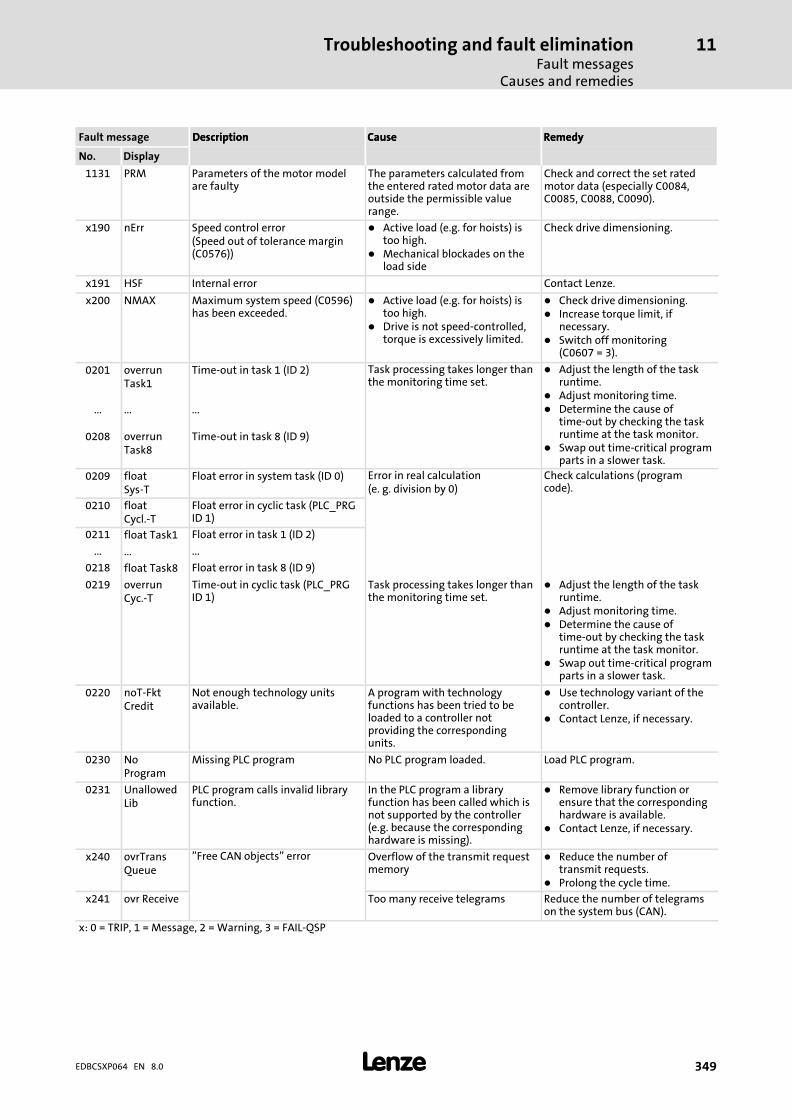
Troubleshooting and fault eliminationFault messages
Causes and remedies
11
� 349EDBCSXP064 EN 8.0
RemedyCauseDescriptionFault message RemedyCauseDescription
DisplayNo.
1131 PRM Parameters of the motor modelare faulty
The parameters calculated fromthe entered rated motor data areoutside the permissible valuerange.
Check and correct the set ratedmotor data (especially C0084,C0085, C0088, C0090).
x190 nErr Speed control error(Speed out of tolerance margin(C0576))
� Active load (e.g. for hoists) istoo high.
� Mechanical blockades on theload side
Check drive dimensioning.
x191 HSF Internal error Contact Lenze.
x200 NMAX Maximum system speed (C0596)has been exceeded.
� Active load (e.g. for hoists) istoo high.
� Drive is not speed−controlled,torque is excessively limited.
� Check drive dimensioning.� Increase torque limit, if
necessary.� Switch off monitoring
(C0607 = 3).
0201 overrunTask1
Time−out in task 1 (ID 2) Task processing takes longer thanthe monitoring time set.
� Adjust the length of the taskruntime.
� Adjust monitoring time.� Determine the cause of
time−out by checking the taskruntime at the task monitor.
� Swap out time−critical programparts in a slower task.
... ... ...
0208 overrunTask8
Time−out in task 8 (ID 9)
0209 floatSys−T
Float error in system task (ID 0) Error in real calculation(e. g. division by 0)
Check calculations (programcode).
0210 floatCycl.−T
Float error in cyclic task (PLC_PRGID 1)
0211 float Task1 Float error in task 1 (ID 2)
... ... ...
0218 float Task8 Float error in task 8 (ID 9)
0219 overrunCyc.−T
Time−out in cyclic task (PLC_PRGID 1)
Task processing takes longer thanthe monitoring time set.
� Adjust the length of the taskruntime.
� Adjust monitoring time.� Determine the cause of
time−out by checking the taskruntime at the task monitor.
� Swap out time−critical programparts in a slower task.
0220 noT−FktCredit
Not enough technology unitsavailable.
A program with technologyfunctions has been tried to beloaded to a controller notproviding the correspondingunits.
� Use technology variant of thecontroller.
� Contact Lenze, if necessary.
0230 NoProgram
Missing PLC program No PLC program loaded. Load PLC program.
0231 UnallowedLib
PLC program calls invalid libraryfunction.
In the PLC program a libraryfunction has been called which isnot supported by the controller(e.g. because the correspondinghardware is missing).
� Remove library function orensure that the correspondinghardware is available.
� Contact Lenze, if necessary.
x240 ovrTransQueue
"Free CAN objects" error Overflow of the transmit requestmemory
� Reduce the number oftransmit requests.
� Prolong the cycle time.
x241 ovr Receive Too many receive telegrams Reduce the number of telegramson the system bus (CAN).
x: 0 = TRIP, 1 = Message, 2 = Warning, 3 = FAIL−QSP

Troubleshooting and fault eliminationFault messagesCauses and remedies
11
� 350 EDBCSXP064 EN 8.0
RemedyCauseDescriptionFault message RemedyCauseDescription
DisplayNo.
x260 Err NodeGuard
"Life guarding event" The controller configured as CANslave does not receive a "NodeGuarding" telegram within the"Node Life Time" from the CANmaster.
� Check wiring at X4.� Check CAN configuration.� Make sure that "Node
Guarding" has been activatedin the CAN master.
� Adapt "Node Life Time"(C0382) to the setting in theCAN master.
2402 PosPosLimit Positive software limit position(C3040) has been reached.
Positive software limit positionreached in manual jog mode(inching mode).
� Check travel range.� Check positive software limit
position C3040.
2403 NegPosLimit
Negative software limit position(C3041) has been reached.
The negative software limitposition has been reached in themanual control mode.
� Check travel range.� Check negative software limit
position C3041.
2404 FollowErrWarn
Following error tolerance (C3030)reached.
The drive cannot follow thesetpoint.
� Reduce acceleration.� Increase the limit value C3030.� Increase current limit C0022
(observe max. motor current).� Check drive dimensioning.
2422 InvProfData Impermissible positioning profileparameters
E. g. acceleration, deceleration ortraversing speed = 0
Correct the setting.
2423 OverfllntPos Position setpoint overflow Target position / distance > 231 − 1internal increments
Correct the setting.
2424 SWLimOutOfRan
Impermissible software limitpositions
The software limit position C3040/ C3041 is not specified within thepermissible range (C4265) and isinternally limited to the value ofC4240/C4241.
Correct the setting.
3400 PosLimitSw Positive hardware limit switch hasbeen approached.
Hardware limit switch suppliesLOW signal.
� Check function of hardwarelimit switch.
� Check signal at the digitalinput (X6/DIx).
� Check position of the hardwarelimit switch.
� Check positioning profile modeC3095/x in the positioningprofile.
3401 NegLimitSw Negative hardware limit switchhas been approached.
Hardware limit switch suppliesLOW signal.
� Check function of hardwarelimit switch.
� Check signal at the digitalinput (X6/DIx).
� Check position of the hardwarelimit switch.
� Check positioning profile modeC3095/x in the positioningprofile.
3402 PosPosLimit Positive software limit position(C3040) has been reached.
Positive software limit position inthe positioning profile modereached.
� Check position selectionC3095/x in the positioningprofile.
� Check positive software limitposition C3040.
3403 NegPosLimit
Negative software limit position(C3041) has been reached.
Negative software limit positionin the positioning profile modereached.
� Check position selectionC3095/x in the positioningprofile.
� Check negative software limitposition C3041.
x: 0 = TRIP, 1 = Message, 2 = Warning, 3 = FAIL−QSP
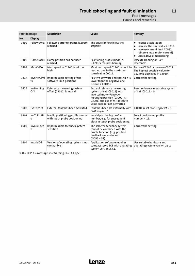
Troubleshooting and fault eliminationFault messages
Causes and remedies
11
� 351EDBCSXP064 EN 8.0
RemedyCauseDescriptionFault message RemedyCauseDescription
DisplayNo.
3405 FollowErrFail
Following error tolerance (C3030)reached.
The drive cannot follow thesetpoint.
� Reduce acceleration.� Increase the limit value C3030.� Increase current limit C0022
(observe max. motor current).� Check drive dimensioning.
3406 HomePosErr Home position has not beenreached.
Positioning profile mode inC3095/x requires homing.
Execute Homing or "Setreference".
3409 MaxVelErr Max. speed in C1240 is set toohigh.
Maximum speed C1240 cannot bereached due to the maximumspeed set in C0011.
Reduce C1240 or increase C0011.The highest possible value forC1240 is displayed in C3060.
3417 InvSftwLimits
Impermissible setting of thesoftware limit positions
Positive software limit position islower than the negative one(C3040 < C3041).
Correct the setting.
0425 InvHomingOffs
Reference measuring systemoffset (C3012) is invalid.
Entry of reference measuringsystem offset (C3012) withinverted motor−/encodermounting position (C3000 <>C3001) and use of MT absolutevalue encoder not permitted
Reset reference measuring systemoffset (C3012 = 0)
3500 ExtTripSet External fault has been activated. Fault has been set externally withCtrl1.TripReset.
C4040: reset Ctrl1.TripReset = 0.
3501 InvTpProfNo
Invalid positioning profile numberwith touch probe positioning
Invalid positioning profilenumber, e. g. for subsequentblock in touch probe positioning
Select positioning profilenumber < 15.
0503 InvalidFeedb
Impermissible feedback systemselection
The selected feedback systemcannot be combined with theprofile function (e. g. positionfeedback = encoder andC3095 = 31).
Correct the setting.
0504 InvalidOS Version of operating system is notcompatible.
Application software requirescompact servo ECS with operatingsystem version ≥ 3.2.
Use suitable hardware andoperating system version ≥ 3.2.
x: 0 = TRIP, 1 = Message, 2 = Warning, 3 = FAIL−QSP

Troubleshooting and fault eliminationFault messagesReset fault messages (TRIP−RESET)
11
� 352 EDBCSXP064 EN 8.0
11.3.2 Reset fault messages (TRIP−RESET)
Response Measures to reset the fault message
TRIP/FAIL−QSP Note!As long as a TRIP/FAIL−QSP source is active, the TRIP/FAIL−QSP cannot be reset.
The TRIP/FAIL−QSP can be reset by:� Press keypad XT EMZ9371 BC /. Then, press . to re−enable the axis module.� Set code C4166 = 1.� Control word "Ctrl1": Control bit Ctrl1.TripReset (� 158)
(Dependent on the control interface selected in C4010.)� Control word AIF (from V3.0)After the TRIP/FAIL−QSP has been reset, the drive remains at standstill.
Message Danger!After the fault has been removed, the fault message is removed automatically and the driverestarts automatically.
Warning After eliminating the fault, the fault message is reset automatically.

AppendixCode table
12
� 353EDBCSXP064 EN 8.0
12 Appendix
12.1 Code table
How to read the code table
Column Abbreviation Meaning
No. Cxxxx Code no. Cxxxx
1 Subcode 1 of Cxxxx
2 Subcode 2 of Cxxxx
Cxxxx Changed input value of the code or subcode is accepted after pressing��.
[Cxxxx] Changed input value of the code or subcode is accepted after pressing�� when the controller is inhibited.
Name LCD display of the keypad XT EMZ9371BC
Lenze/{Appl.} x Lenze setting:� Value at the time of delivery or after loading the Lenze setting using
C0002.
{xxx...} Different application initialisation value� Value at the time of delivery� After loading the Lenze setting using C0002, the application
initialisation value is overwritten with the Lenze setting.� The application initialisation values can be restored by loading the
application software with "Global Drive Loader" (GDL).
� The "Important" column contains further information
Selection 1 {%} 99 minimum value {unit} maximum value
IMPORTANT Short code description
Code Possible settings IMPORTANT
No. Designation Lenze/{Appl.}
Selection
C0002 Par load 0 Load parameter setThe Lenze setting can only beloaded if the controller isinhibited (CINH).
0 Load Lenze setting Load Lenze setting into the RAMand activate it.Only possible if C2108 = 2 (PLCstopped).
1 Load parameter set 1 Load parameter set 1 into theRAM and activate it.Parameter set 1 is loadedautomatically after every mainsconnection.
C0003 Par save 0 Save parameter set
0 Saving completed
1 Save parameter set 1
C0004 Op display 56 Selection of XT keypad statusdisplay
1 {Code no.} 9999 The keypad displays the selectedcode in the operating level, if nostatus messages from C0183 areactive (e. g.: 56 = torque setpoint(C0056))
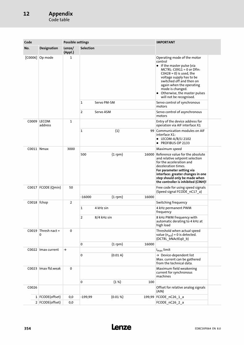
AppendixCode table
12
� 354 EDBCSXP064 EN 8.0
IMPORTANTPossible settingsCode
SelectionLenze/{Appl.}
DesignationNo.
[C0006] Op mode 1 Operating mode of the motorcontrol� If the master pulse (via
MCTRL: C0911 = 0 or DfIn:C0428 = 0) is used, thevoltage supply has to beswitched off and then onagain when the operatingmode is changed.
� Otherwise, the master pulseswill not be recognised.
1 Servo PM−SM Servo control of synchronousmotors
2 Servo ASM Servo control of asynchronousmotors
C0009 LECOMaddress
1 Entry of the device address foroperation via AIF interface X1
1 {1} 99 Communication modules on AIFinterface X1:� LECOM−A/B/LI 2102� PROFIBUS−DP 2133
C0011 Nmax 3000 Maximum speed
500 {1 rpm} 16000 Reference value for the absoluteand relative setpoint selectionfor the acceleration anddeceleration times.For parameter setting viainterface: greater changes in onestep should only be made whenthe controller is inhibited (CINH)!
C0017 FCODE (Qmin) 50 Free code for using speed signals(Speed signal FCODE_nC17_a)
−16000 {1 rpm} 16000
C0018 fchop 2 Switching frequency
1 4 kHz sin 4 kHz permanent PWMfrequency
2 8/4 kHz sin 8 kHz PWM frequency withautomatic derating to 4 kHz athigh load
C0019 Thresh nact =0
0 Threshold when actual speedvalue (nact) = 0 is detected.(DCTRL_bNActEq0_b)
0 {1 rpm} 16000
C0022 Imax current � Imax limit
0 {0.01 A} � Device−dependent listMax. current can be gatheredfrom the technical data.
C0023 Imax fld.weak 0 Maximum field weakeningcurrent for synchronousmachines
0 {1 %} 100
C0026 Offset for relative analog signals(AIN)
1 FCODE(offset) 0,0 −199,99 {0.01 %} 199,99 FCODE_nC26_1_a
2 FCODE(offset) 0,0 FCODE_nC26_2_a
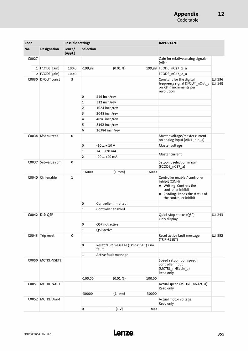
AppendixCode table
12
� 355EDBCSXP064 EN 8.0
IMPORTANTPossible settingsCode
SelectionLenze/{Appl.}
DesignationNo.
C0027 Gain for relative analog signals(AIN)
1 FCODE(gain) 100,0 −199,99 {0.01 %} 199,99 FCODE_nC27_1_a
2 FCODE(gain) 100,0 FCODE_nC27_2_a
C0030 DFOUT const 3 Constant for the digitalfrequency signal DFOUT_nOut_von X8 in increments perrevolution
� 136� 145
0 256 incr./rev
1 512 incr./rev
2 1024 incr./rev
3 2048 incr./rev
4 4096 incr./rev
5 8192 incr./rev
6 16384 incr./rev
C0034 Mst current 0 Master voltage/master currenton analog input (AIN1_nIn_a)
0 −10 ... + 10 V Master voltage
1 +4 ... +20 mAMaster current
2 −20 ... +20 mA
C0037 Set−value rpm 0 Setpoint selection in rpm(FCODE_nC37_a)
−16000 {1 rpm} 16000
C0040 Ctrl enable 1 Controller enable / controllerinhibit (CINH)� Writing: Controls the
controller inhibit� Reading: Reads the status of
the controller inhibit
0 Controller inhibited
1 Controller enabled
C0042 DIS: QSP Quick stop status (QSP)Only display
� 243
0 QSP not active
1 QSP active
C0043 Trip reset 0 Reset active fault message(TRIP−RESET)
� 352
0 Reset fault message (TRIP−RESET) / nofault
1 Active fault message
C0050 MCTRL−NSET2 Speed setpoint on speedcontroller input(MCTRL_nNSetIn_a)Read only
−100,00 {0.01 %} 100.00
C0051 MCTRL−NACT Actual speed (MCTRL_nNAct_a)Read only
−30000 {1 rpm} 30000
C0052 MCTRL Umot Actual motor voltageRead only
0 {1 V} 800

AppendixCode table
12
� 356 EDBCSXP064 EN 8.0
IMPORTANTPossible settingsCode
SelectionLenze/{Appl.}
DesignationNo.
C0053 UG−VOLTAGE DC−bus voltageRead only
0 {1 V} 900
C0054 Imot Actual motor currentRead only
0,0 {0.1 A} 500,0
C0055 Phase current Motor phase currentRead only
1 iu 0,0 {0.1 A} 500,0 Actual current in U phase
2 iv Actual current in V phase
3 iw Actual current in W phase
4 Io Actual theoretical star−pointcurrent
C0056 MCTRL−MSET2 Torque setpoint on speedcontroller output(MCTRL_nMSetIn_a)Read only
−100 {1 %} 100
C0057 Max Torque Maximum possible torque of thedrive configurationDependent on C0022, C0081,C0087, C0088Read only
0,0 {0.1 Nm} 500,0
C0058 Rotor diff −90.0 Rotor displacement angle (offsetangle)Input in case of Lenze motor with� resolver: −90°� hiperface absolute value
encoder: 0°Code value is adapted by therotor position adjustmentfunction (C0095).Only relevant for the operationof synchronous motors.
� 249
−180.0 {0.1 �} 179.9
C0059 Mot pole no. Calculated number of motor polepairsRead only
1 {1} 200
C0060 Rotor pos Current rotor position; value isderived from position encoder.Therefore, it is only valid as rotorposition if the position encodersettings under C0490 areidentical with the settings of thespeed encoder on the motorshaft under C0495.Read only
� 246
0 {1 inc} 2047 Display with reduced resolution:1 revolution = 2048 increments
C0061 Heatsinktemp
Heatsink temperatureRead only
� 303
−200 {1 °C} 200
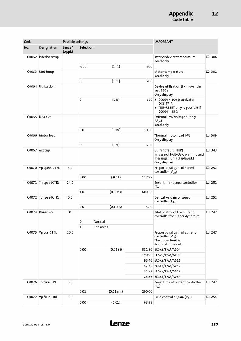
AppendixCode table
12
� 357EDBCSXP064 EN 8.0
IMPORTANTPossible settingsCode
SelectionLenze/{Appl.}
DesignationNo.
C0062 Interior temp Interior device temperatureRead only
� 304
−200 {1 °C} 200
C0063 Mot temp Motor temperatureRead only
� 301
0 {1 °C} 200
C0064 Utilization Device utilisation (I x t) over thelast 180 sOnly display
0 {1 %} 150 � C0064 > 100 % activatesOC5−TRIP.
� TRIP−RESET only is possible ifC0064 < 95 %.
C0065 U24 ext External low−voltage supply(U24)Read only
0,0 {0.1V} 100,0
C0066 Motor load Thermal motor load I2xtOnly display
� 309
0 {1 %} 250
C0067 Act trip Current fault (TRIP)(in case of FAIL−QSP, warning andmessage, "0" is displayed.)Only display
� 343
C0070 Vp speedCTRL 3.0 Proportional gain of speedcontroller (Vpn)
� 252
0.00 { 0.01} 127.99
C0071 Tn speedCTRL 24.0 Reset time − speed controller(Tnn)
� 252
1.0 {0.5 ms} 6000.0
C0072 Td speedCTRL 0.0 Derivative gain of speedcontroller (Tdn)
� 252
0.0 {0.1 ms} 32.0
C0074 Dynamics 0 Pilot control of the currentcontroller for higher dynamics
� 247
0 Normal
1 Enhanced
C0075 Vp currCTRL 20.0 Proportional gain of currentcontroller (Vpi)The upper limit isdevice−dependent.
� 247
0.00 {0.01 �} 381.80 ECSxS/P/M/A004
190.90 ECSxS/P/M/A008
95.46 ECSxS/P/M/A016
47.72 ECSxS/P/M/A032
31.82 ECSxS/P/M/A048
23.86 ECSxS/P/M/A064
C0076 Tn currCTRL 5.0 Reset time of current controller(Tni)
� 247
0.01 {0.01 ms} 200.00
C0077 Vp fieldCTRL 5.0 Field controller gain (VpF) � 254
0.00 {0.01} 63.99

AppendixCode table
12
� 358 EDBCSXP064 EN 8.0
IMPORTANTPossible settingsCode
SelectionLenze/{Appl.}
DesignationNo.
C0078 Tn fieldCTRL 20.0 Field controller reset time (TnF) � 254
1.0 {0.5 ms} 6000.0
C0079 DIS:Lh Mutual inductance of theasynchronous motorRead only
0.0 {0.1 mH} 3276.7
[C0080] Res pole no. 1 Number of pole pairs of resolver
1 {1} 10
[C0081] Mot power 3.20 Rated motor power according tonameplate
0.01 {0.01 kW} 500.00
[C0082] DIS:Rr Rotor resistance of theasynchronous motorRead only
0.000 {0.001 �} 32.767
C0083 DIS:Tr Rotor time constant of theasynchronous motorRead only
0.00 {0.01 ms} 327.67
[C0084] Mot Rs 1.10 Stator resistance of the motorThe upper limit isdevice−dependent.
0.00 {0.01 �} 95.44 ECSxS/P/M/A004
47.72 ECSxS/P/M/A008
23.86 ECSxS/P/M/A016
11.93 ECSxS/P/M/A032
7.95 ECSxS/P/M/A048
5.96 ECSxS/P/M/A064
[C0085] Mot Ls 5.30 Leakage inductance of the motor
0.00 {0.01 mH} 200.00
[C0087] Mot speed 3700 Rated motor speed
300 {1 rpm} 16000
[C0088] Mot current 7.0 Rated motor current
0.5 {0.1 A} 500.0
[C0089] Motfrequency
185 Rated motor frequency
10 {1 Hz} 1000
[C0090] Mot voltage 325 Rated motor voltage
50 {1 V} 500
[C0091] Mot cos phi 1.0 cos � of the asynchronous motor
0.50 {0.01} 1.00
C0092 DIS:Isdeff Magnetising current of theasynchronous motorRead only
0.00 {0.01 A} 327,67
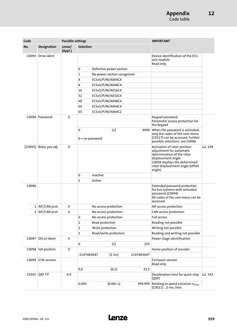
AppendixCode table
12
� 359EDBCSXP064 EN 8.0
IMPORTANTPossible settingsCode
SelectionLenze/{Appl.}
DesignationNo.
C0093 Drive ident Device identification of the ECSaxis moduleRead only
0 Defective power section
1 No power section recognised
4 ECSxS/P/M/A004C4
8 ECSxS/P/M/A008C4
16 ECSxS/P/M/A016C4
32 ECSxS/P/M/A032C4
48 ECSxS/P/M/A048C4
64 ECSxS/P/M/A064C4
65 ECSxS/P/M/A064C2
C0094 Password 0 Keypad passwordParameter access protection forthe keypad
0 {1} 9999 When the password is activated,only the codes of the user menu(C0517) can be accessed. Furtherpossible selections: see C0096
0 = no password
[C0095] Rotor pos adj 0 Activation of rotor positionadjustment for automaticdetermination of the rotordisplacement angle.C0058 displays the determinedrotor displacement angle (offsetangle).
� 249
0 Inactive
1 Active
C0096 Extended password protectionfor bus systems with activatedpassword (C0094)All codes in the user menu can beaccessed.
1 AIF/CAN prot. 0 No access protection AIF access protection
2 AIF/CAN prot. 0 No access protection CAN access protection
0 No access protection Full access
1 Read protection Reading not possible
2 Write protection Writing not possible
3 Read/write protection Reading and writing not possible
C0097 DIS:Lt−Ident 0 Power stage identification
0 {1} 255
C0098 Set position 0 Home position of encoder
−2147483647 {1 inc} 2147483647
C0099 S/W version Firmware versionRead only
0,0 {0,1} 25,5
C0105 QSP Tif 0.0 Deceleration time for quick stop(QSP)
� 243
0.000 {0.001 s} 999.999 Relating to speed variation nmax(C0011) ...0 rev./min.
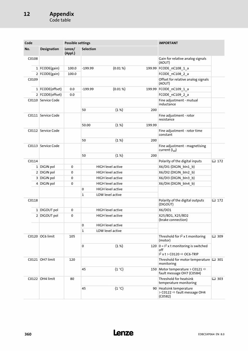
AppendixCode table
12
� 360 EDBCSXP064 EN 8.0
IMPORTANTPossible settingsCode
SelectionLenze/{Appl.}
DesignationNo.
C0108 Gain for relative analog signals(AOUT)
1 FCODE(gain) 100.0 −199.99 {0.01 %} 199.99 FCODE_nC108_1_a
2 FCODE(gain) 100.0 FCODE_nC108_2_a
C0109 Offset for relative analog signals(AOUT)
1 FCODE(offset) 0.0 −199.99 {0.01 %} 199.99 FCODE_nC109_1_a
2 FCODE(offset) 0.0 FCODE_nC109_2_a
C0110 Service Code Fine adjustment − mutualinductance
50 {1 %} 200
C0111 Service Code Fine adjustment − rotorresistance
50.00 {1 %} 199.99
C0112 Service Code Fine adjustment − rotor timeconstant
50 {1 %} 200
C0113 Service Code Fine adjustment − magnetisingcurrent (Isd)
50 {1 %} 200
C0114 Polarity of the digital inputs � 172
1 DIGIN pol 0 HIGH level active X6/DI1 (DIGIN_bIn1_b)
2 DIGIN pol 0 HIGH level active X6/DI2 (DIGIN_bIn2_b)
3 DIGIN pol 0 HIGH level active X6/DI3 (DIGIN_bIn3_b)
4 DIGIN pol 0 HIGH level active X6/DI4 (DIGIN_bIn4_b)
0 HIGH level active
1 LOW level active
C0118 Polarity of the digital outputs(DIGOUT)
� 172
1 DIGOUT pol 0 HIGH level active X6/DO1
2 DIGOUT pol 0 HIGH level active X25/BD1, X25/BD2(brake connection)
0 HIGH level active
1 LOW level active
C0120 OC6 limit 105 Threshold for I2 x t monitoring(motor)
� 309
0 {1 %} 120 0 = I2 x t monitoring is switchedoffI2 x t > C0120 OC6−TRIP
C0121 OH7 limit 120 Threshold for motor temperaturemonitoring
� 301
45 {1 °C} 150 Motor temperature > C0121 fault message OH7 (C0584)
C0122 OH4 limit 80 Threshold for heatsinktemperature monitoring
� 303
45 {1 °C} 90 Heatsink temperature> C0122 fault message OH4(C0582)

AppendixCode table
12
� 361EDBCSXP064 EN 8.0
IMPORTANTPossible settingsCode
SelectionLenze/{Appl.}
DesignationNo.
C0123 OC7 limit 90 Threshold for I x t warning (axismodule)
� 300
0 {1 %} 100 C0064 > C0123 fault messageOC7 (C0604)
C0124 OH5 limit 75 Threshold for temperaturemonitoring inside the device
� 304
10 {1 %} 90 C0062 > C0124 fault messageOH5 (C0605)
C0125 Baud rate 0 Baud rate for operation via AIFinterface X1
0 9600 bit/s Communication modules on AIFinterface X1:� LECOM−A/B/LI 2102� PROFIBUS−DP 2133
1 4800 bits/s
2 2400 bit/s
3 1200 bit/s
4 19200 bit/s
C0126 MONIT CE0 3 Fault response regarding themonitoring of communicationvia AIF interface X1.� Via C2382 you can select
whether controller inhibit(CINH) or quick stop (QSP) isactivated when a CE0 faultoccurs.
0 TRIP A communication error activatesthe CE0 response set.2 Warning
3 Off Monitoring switched off.
C0127 OC8 limit 100 Threshold for I2 x t warning(motor)
� 309
0 {1 %} 120 I2 x t > C0127 fault messageOC8 (C0606)
C0128 Tau motor 5.0 Thermal time constant of themotor
� 309
0.5 {0.1 min} 25.0 For calculating the I2 x tdisconnection
C0129 Charc.: Ix/Nx Reduction of the speed/torquecharacteristic for UL−compliantthermal motor monitoring (I2 x t)The reduced speed/torquecharacteristic reduces thepermissible thermal load ofself−ventilated standard motors.
� 24
1 100 10 {1 %} 200 S1 torque characteristic I1/IratedThis value also enables anincrease of the maximallypermissible utilisation.
2 40 S1 torque characteristicsn2/nratedWith increasing speeds, themaximally permissibleutilisation remains unchanged(IMot = Irated).

AppendixCode table
12
� 362 EDBCSXP064 EN 8.0
IMPORTANTPossible settingsCode
SelectionLenze/{Appl.}
DesignationNo.
C0135 Control word 0 System control word DCTRL
0 {1} 65535 Controller evaluates informationas 16 bits (binary−coded)
Bit 0 Not assigned
Bit 1 Not assigned
Bit 2 Not assigned
Bit 3 Quick stop (QSP)
Bit 4 Not assigned
Bit 5 Not assigned
Bit 6 Not assigned
Bit 7 Not assigned
Bit 8 Operation inhibit (DISABLE)
Bit 9 Controller inhibit (CINH)
Bit 10 TRIP−SET
Bit 11 TRIP−RESET
Bit 12 Not assigned
Bit 13 Not assigned
Bit 14 Not assigned
Bit 15 Not assigned
C0136 Control wordsHexadecimal value is bit−coded.Read only
1 CTRLWORD 0 {hex} FFFF Control word C0135
2 CTRLWORD CAN control word
3 CTRLWORD AIF control word
C0141 FCODE(setval) 0.0 Main setpoint (FCODE_C141_a)
−199.99 {0.01 %} 199.99
C0142 Start options 1 Starting condition for start after� mains connection� message (t > 0.5 s)� TRIP
0 Protection against unexpected start−up
1 Automatic start
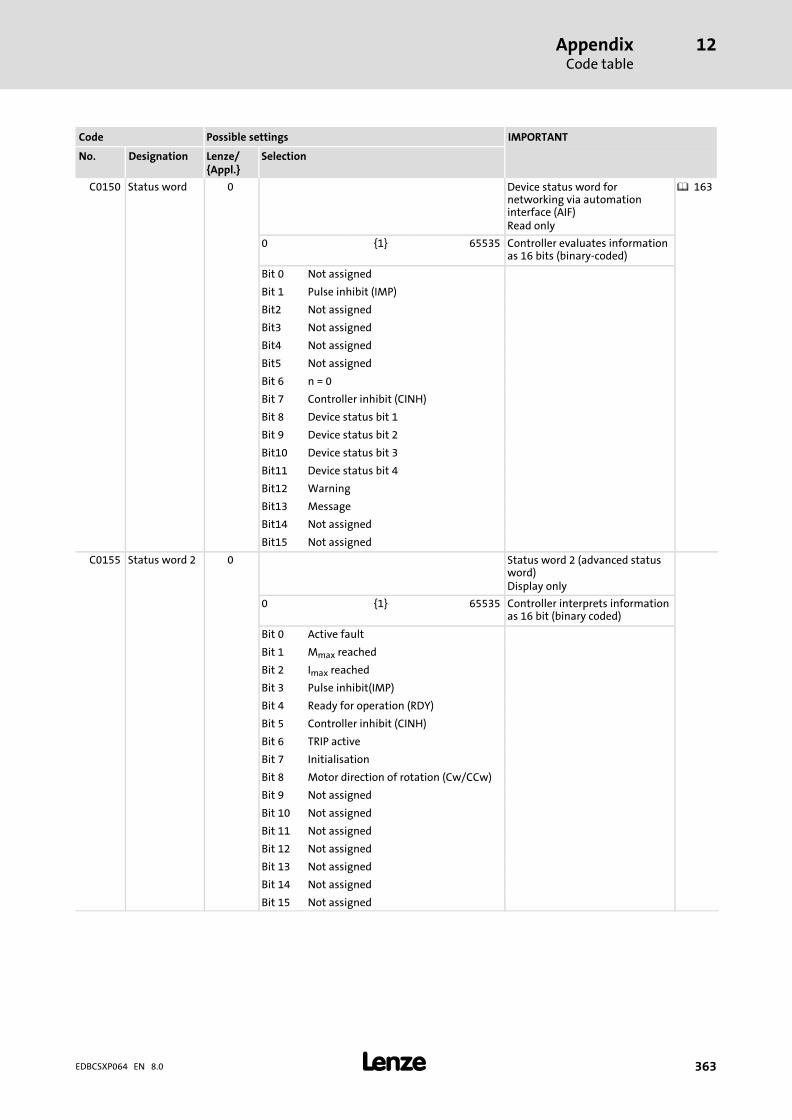
AppendixCode table
12
� 363EDBCSXP064 EN 8.0
IMPORTANTPossible settingsCode
SelectionLenze/{Appl.}
DesignationNo.
C0150 Status word 0 Device status word fornetworking via automationinterface (AIF)Read only
� 163
0 {1} 65535 Controller evaluates informationas 16 bits (binary−coded)
Bit 0 Not assigned
Bit 1 Pulse inhibit (IMP)
Bit2 Not assigned
Bit3 Not assigned
Bit4 Not assigned
Bit5 Not assigned
Bit 6 n = 0
Bit 7 Controller inhibit (CINH)
Bit 8 Device status bit 1
Bit 9 Device status bit 2
Bit10 Device status bit 3
Bit11 Device status bit 4
Bit12 Warning
Bit13 Message
Bit14 Not assigned
Bit15 Not assigned
C0155 Status word 2 0 Status word 2 (advanced statusword)Display only
0 {1} 65535 Controller interprets informationas 16 bit (binary coded)
Bit 0 Active fault
Bit 1 Mmax reached
Bit 2 Imax reached
Bit 3 Pulse inhibit(IMP)
Bit 4 Ready for operation (RDY)
Bit 5 Controller inhibit (CINH)
Bit 6 TRIP active
Bit 7 Initialisation
Bit 8 Motor direction of rotation (Cw/CCw)
Bit 9 Not assigned
Bit 10 Not assigned
Bit 11 Not assigned
Bit 12 Not assigned
Bit 13 Not assigned
Bit 14 Not assigned
Bit 15 Not assigned

AppendixCode table
12
� 364 EDBCSXP064 EN 8.0
IMPORTANTPossible settingsCode
SelectionLenze/{Appl.}
DesignationNo.
C0157 Status of free bits of DCTRLstatus word 1 (C0150)Only display
1 Stat. FreeBit 0 {1 bit} 1 Bit 0 (DCTRL_bStat_B0_b)
2 Stat. FreeBit Bit 2 (DCTRL_bStat_B2_b)
3 Stat. FreeBit Bit 3 (DCTRL_bStat_B3_b)
4 Stat. FreeBit Bit 4 (DCTRL_bStat_B4_b)
5 Stat. FreeBit Bit 5 (DCTRL_bStat_B5_b)
6 Stat. FreeBit Bit 14 (DCTRL_bStat_B14_b)
7 Stat. FreeBit Bit 15 (DCTRL_bStat_B15_b)
C0161 Act trip Current TRIP� as in C0168/1� In case of FAIL−QSP, warning,
and message, "0" is displayed.Only display
� 343
C0167 Reset failmem 0 Delete history buffer (C0168) � 338
0 No reaction
1 Delete history buffer
C0168 Fault history buffer (list of faultsoccurred)Read only
� 338� 343
1 Fail number Currently active fault
2 Fail number Last fault
3 Fail number Last fault but one
4 Fail number Last fault but two
5 Fail number Last fault but three
6 Fail number Last fault but four
7 Fail number Last fault but five
8 Fail number Last fault but six
All fault indications(TRIP, FAIL−QSP, warning, message)
C0169 Time at which the faultmessages entered in the historybuffer (C0168) occurred.Read only
� 338
1 FailTime Respective status of the operating hour counter(C0179)
Occurrence of the currentlyactive fault message
2 FailTime Occurrence of the last faultmessage
3 FailTime Occurrence of the second−lastfault message
4 FailTime Occurrence of the third−last faultmessage
5 FailTime Occurrence of the fourth−lastfault message
6 FailTime Occurrence of the fifth−last faultmessage
7 FailTime Occurrence of the sixth−last faultmessage
8 FailTime Occurrence of the seventh−lastfault message
0 {1 h} 65535
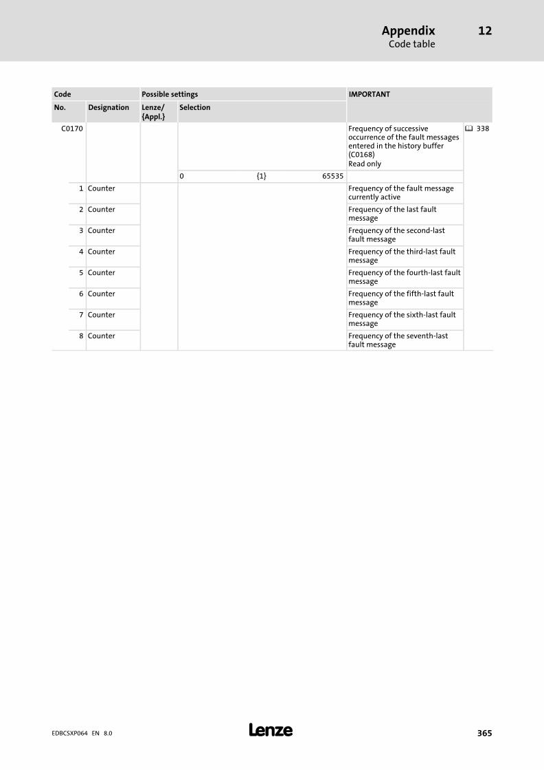
AppendixCode table
12
� 365EDBCSXP064 EN 8.0
IMPORTANTPossible settingsCode
SelectionLenze/{Appl.}
DesignationNo.
C0170 Frequency of successiveoccurrence of the fault messagesentered in the history buffer(C0168)Read only
� 338
0 {1} 65535
1 Counter Frequency of the fault messagecurrently active
2 Counter Frequency of the last faultmessage
3 Counter Frequency of the second−lastfault message
4 Counter Frequency of the third−last faultmessage
5 Counter Frequency of the fourth−last faultmessage
6 Counter Frequency of the fifth−last faultmessage
7 Counter Frequency of the sixth−last faultmessage
8 Counter Frequency of the seventh−lastfault message
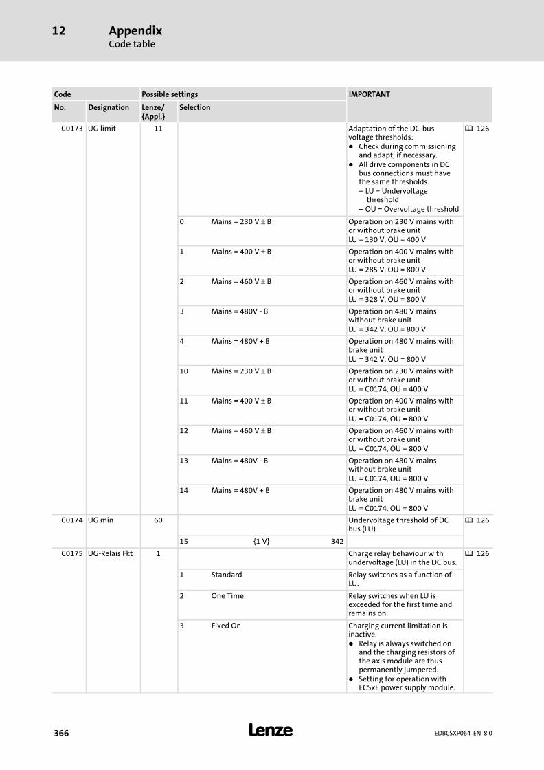
AppendixCode table
12
� 366 EDBCSXP064 EN 8.0
IMPORTANTPossible settingsCode
SelectionLenze/{Appl.}
DesignationNo.
C0173 UG limit 11 Adaptation of the DC−busvoltage thresholds:� Check during commissioning
and adapt, if necessary.� All drive components in DC
bus connections must havethe same thresholds.– LU = Undervoltage
threshold– OU = Overvoltage threshold
� 126
0 Mains = 230 V � B Operation on 230 V mains withor without brake unitLU = 130 V, OU = 400 V
1 Mains = 400 V � B Operation on 400 V mains withor without brake unitLU = 285 V, OU = 800 V
2 Mains = 460 V � B Operation on 460 V mains withor without brake unitLU = 328 V, OU = 800 V
3 Mains = 480V − B Operation on 480 V mainswithout brake unitLU = 342 V, OU = 800 V
4 Mains = 480V + B Operation on 480 V mains withbrake unitLU = 342 V, OU = 800 V
10 Mains = 230 V � B Operation on 230 V mains withor without brake unitLU = C0174, OU = 400 V
11 Mains = 400 V � B Operation on 400 V mains withor without brake unitLU = C0174, OU = 800 V
12 Mains = 460 V � B Operation on 460 V mains withor without brake unitLU = C0174, OU = 800 V
13 Mains = 480V − B Operation on 480 V mainswithout brake unitLU = C0174, OU = 800 V
14 Mains = 480V + B Operation on 480 V mains withbrake unitLU = C0174, OU = 800 V
C0174 UG min 60 Undervoltage threshold of DCbus (LU)
� 126
15 {1 V} 342
C0175 UG−Relais Fkt 1 Charge relay behaviour withundervoltage (LU) in the DC bus.
� 126
1 Standard Relay switches as a function ofLU.
2 One Time Relay switches when LU isexceeded for the first time andremains on.
3 Fixed On Charging current limitation isinactive.� Relay is always switched on
and the charging resistors ofthe axis module are thuspermanently jumpered.
� Setting for operation withECSxE power supply module.

AppendixCode table
12
� 367EDBCSXP064 EN 8.0
IMPORTANTPossible settingsCode
SelectionLenze/{Appl.}
DesignationNo.
C0178 Op timer Running time meterRead only
0 {1 sec} 4294967295 Time when the controller wasenabled
C0179 Mains timer Power−on time meterOnly display
0 {1 sec} 4294967295 Time when the mains wasswitched on
C0183 Diagnostics Drive diagnosticsRead only� Indicates fault or status
information� If several fault or status
information are to be shownat the same time, theinformation with the smallestnumber is displayed
0 OK No fault
101 Initialisation phase
102 TRIP/trouble
103 Emergency stop activated
104 IMP message
105 Power off
111 Operation inhibit C0135
112 Operation inhibit AIF
113 Operation inhibit CAN
121 Controller inhibit via X6/SI1
122 Internal controller inhibit 1
123 Internal controller inhibit 2
124 Controller inhibit via STOP key of thekeypad
125 Controller inhibit via AIF
126 Controller inhibit via CAN
131 Fail QSP
141 Restart protection
142 Pulse inhibit High resistance power outputs
151 Quick stop (QSP) via terminal
152 Quick stop (QSP) via STOP key of thekeypad
153 Quick stop (QSP) via AIF
154 Quick stop (QSP) via CAN
160 PLC Stop PLC must be started.
250 Warning
C0199 BuildNumber Software identificationOnly display
C0200 S/W Id Software identificationOnly display
C0201 S/W date Software release dateRead only

AppendixCode table
12
� 368 EDBCSXP064 EN 8.0
IMPORTANTPossible settingsCode
SelectionLenze/{Appl.}
DesignationNo.
C0202 Service codeOnly display
1 Product code 1
... ...
4 Product code 4
C0203 Komm.−No. x / xxxx / xxxxx Commission numberOnly display
C0204 Serial−No. Serial numberRead only
C0205 PLC Target ID Identification keyOnly display
C0206 Product. date Production dateOnly display
C0207 DL info 1 Download info 1Only display
C0208 DL info 2 Download info 2Only display
C0209 DL info 3 Download info 3Only display
C0250 FCODE 1 Bit 0 Freely selectable digital signal(1 bit)
0 1
C0254 Vp angle CTRL 0.4000 Phase controller gain (Vp)
0.0000 { 0.0001} 3.9999
C0300 Service Codes Only the Lenze service is allowedto make changes!...
C0302
C0349 Status of the DIP switch for CANbus interface X4Read only
1 CAN DIP−SW 0 {1} 63 Node address set on the DIPswitch
2 CAN DIP−SW 0 4 For setting the DIP switches > 4,the display is set to 0.
C0350 CAN address 32 Node address for CAN businterface X4� This code is not active if one
of the switches 2 ... 7 of theDIP switch is set to "ON".(� 266)
� After the setting process, areset node is required.
� A definite node address mustbe assigned to each CANnode.
� 266� 429
1 {1} 63
C0351 CAN baud rate 0 Baud rate for CAN bus interfaceX4� The baud rate must be set
identically for all CAN nodes.� This code is not active if one
of the switches 2 ... 7 of theDIP switch is set to "ON".
� After the setting process, areset node is required.
� 266
0 500 kbps
1 250 kbits/sec
2 125 kbit/s
3 50 kbps
4 1000 kbit/s
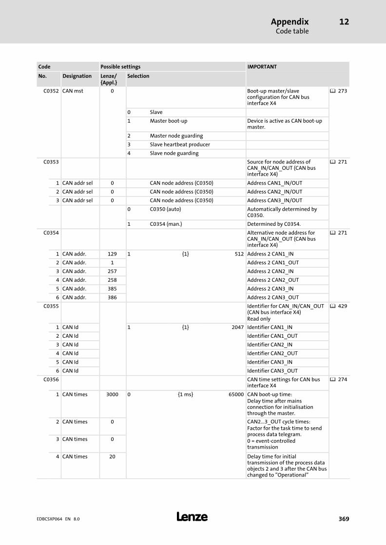
AppendixCode table
12
� 369EDBCSXP064 EN 8.0
IMPORTANTPossible settingsCode
SelectionLenze/{Appl.}
DesignationNo.
C0352 CAN mst 0 Boot−up master/slaveconfiguration for CAN businterface X4
� 273
0 Slave
1 Master boot−up Device is active as CAN boot−upmaster.
2 Master node guarding
3 Slave heartbeat producer
4 Slave node guarding
C0353 Source for node address ofCAN_IN/CAN_OUT (CAN businterface X4)
� 271
1 CAN addr sel 0 CAN node address (C0350) Address CAN1_IN/OUT
2 CAN addr sel 0 CAN node address (C0350) Address CAN2_IN/OUT
3 CAN addr sel 0 CAN node address (C0350) Address CAN3_IN/OUT
0 C0350 (auto) Automatically determined byC0350.
1 C0354 (man.) Determined by C0354.
C0354 Alternative node address forCAN_IN/CAN_OUT (CAN businterface X4)
� 271
1 CAN addr. 129 1 {1} 512 Address 2 CAN1_IN
2 CAN addr. 1 Address 2 CAN1_OUT
3 CAN addr. 257 Address 2 CAN2_IN
4 CAN addr. 258 Address 2 CAN2_OUT
5 CAN addr. 385 Address 2 CAN3_IN
6 CAN addr. 386 Address 2 CAN3_OUT
C0355 Identifier for CAN_IN/CAN_OUT(CAN bus interface X4)Read only
� 429
1 CAN Id 1 {1} 2047 Identifier CAN1_IN
2 CAN Id Identifier CAN1_OUT
3 CAN Id Identifier CAN2_IN
4 CAN Id Identifier CAN2_OUT
5 CAN Id Identifier CAN3_IN
6 CAN Id Identifier CAN3_OUT
C0356 CAN time settings for CAN businterface X4
� 274
1 CAN times 3000 0 {1 ms} 65000 CAN boot−up time:Delay time after mainsconnection for initialisationthrough the master.
2 CAN times 0 CAN2...3_OUT cycle times:Factor for the task time to sendprocess data telegram.0 = event−controlledtransmission
3 CAN times 0
4 CAN times 20 Delay time for initialtransmission of the process dataobjects 2 and 3 after the CAN buschanged to "Operational"

AppendixCode table
12
� 370 EDBCSXP064 EN 8.0
IMPORTANTPossible settingsCode
SelectionLenze/{Appl.}
DesignationNo.
C0357 Monitoring time for CAN1...3_IN(CAN bus interface X4)
� 297
1 CE monit time 3000 1 {1 ms} 65000 CE1 monitoring time
2 CE monit time 3000 CE2 monitoring time
3 CE monit time 3000 CE3 monitoring time
C0358 Reset node 0 Make a reset node for the CANbus node.
� 276
0 No function
1 CAN reset
C0359 CAN state CAN bus status (interface X4)Read only
� 286
0 Operational
1 Pre−operational
2 Warning
3 Bus off
4 Stopped
C0360 Telegram counterCAN_IN/CAN_OUT (CAN businterface X4), number oftelegramsRead only
� 287
1 CANMessages
0 {1} 65535 All sent telegrams
2 CANMessages
With a count value � 65535 the counter restartswith 0
All received telegrams
3 CANMessages
Sent to CAN1_OUT
4 CANMessages
Sent to CAN2_OUT
5 CANMessages
Sent to CAN3_OUT
6 CANMessages
Sent on parameter datachannel 1
7 CANMessages
Sent on parameter datachannel 2
8 CANMessages
Received from CAN1_IN
9 CANMessages
Received from CAN2_IN
10 CANMessages
Received from CAN3_IN
11 CANMessages
Received from parameter datachannel 1
12 CANMessages
Received from parameter datachannel 2

AppendixCode table
12
� 371EDBCSXP064 EN 8.0
IMPORTANTPossible settingsCode
SelectionLenze/{Appl.}
DesignationNo.
C0361 Detected loadCAN_IN/CAN_OUT (CAN businterface X4)Read onlyA faultless operation is onlyguaranteed if the total bus loadof all connected nodes amountsto a value � 80 %.
� 288
1 Load IN/OUT 0 {1 %} 100 All sent telegrams
2 Load IN/OUT All received telegrams
3 Load IN/OUT Sent to CAN1_OUT
4 Load IN/OUT Sent to CAN2_OUT
5 Load IN/OUT Sent to CAN3_OUT
6 Load IN/OUT Sent on parameter datachannel 1
7 Load IN/OUT Sent on parameter datachannel 2
8 Load IN/OUT Received from CAN1_IN
9 Load IN/OUT Received from CAN2_IN
10 Load IN/OUT Received from CAN3_IN
11 Load IN/OUT Received from parameter datachannel 1
12 Load IN/OUT Received from parameter datachannel 2
C0362 Sync cycle Time interval between 2 synctelegrams via the X4 CAN businterface or EMF2192IB EtherCATcommunication module at X1 AIFinterfaceRead only
� 278
1 {1 ms} 30
C0363 Sync correct. 1 Sync correction increment (forCAN and EtherCAT)� Change correction value until
C4264 reaches the minimum.
� 279
1 0.2 �s/ms
2 0.4 �s/ms
3 0.6 �s/ms
4 0.8 �s/ms
5 1.0 �s/ms
C0365 DIS:CANactive
Input signal CAN activeOnly display
0 CAN not active
1 CAN active
C0366 Sync Response 1 CAN sync response for interfaceX4 (CAN)The value "1" should always beset!
� 281
0 No response
1 Response
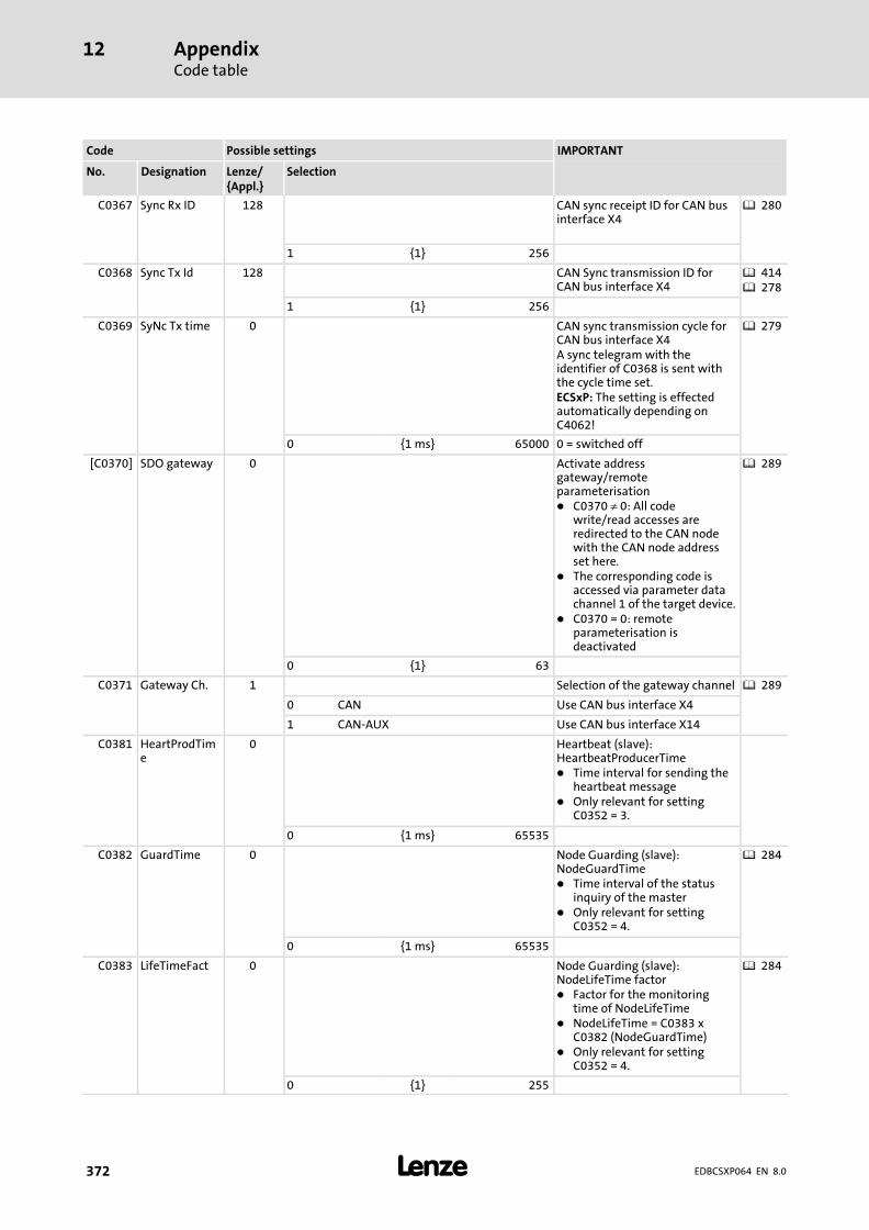
AppendixCode table
12
� 372 EDBCSXP064 EN 8.0
IMPORTANTPossible settingsCode
SelectionLenze/{Appl.}
DesignationNo.
C0367 Sync Rx ID 128 CAN sync receipt ID for CAN businterface X4
� 280
1 {1} 256
C0368 Sync Tx Id 128 CAN Sync transmission ID forCAN bus interface X4
� 414� 278
1 {1} 256
C0369 SyNc Tx time 0 CAN sync transmission cycle forCAN bus interface X4A sync telegram with theidentifier of C0368 is sent withthe cycle time set.ECSxP: The setting is effectedautomatically depending onC4062!
� 279
0 {1 ms} 65000 0 = switched off
[C0370] SDO gateway 0 Activate addressgateway/remoteparameterisation� C0370 � 0: All code
write/read accesses areredirected to the CAN nodewith the CAN node addressset here.
� The corresponding code isaccessed via parameter datachannel 1 of the target device.
� C0370 = 0: remoteparameterisation isdeactivated
� 289
0 {1} 63
C0371 Gateway Ch. 1 Selection of the gateway channel � 289
0 CAN Use CAN bus interface X4
1 CAN−AUX Use CAN bus interface X14
C0381 HeartProdTime
0 Heartbeat (slave):HeartbeatProducerTime� Time interval for sending the
heartbeat message� Only relevant for setting
C0352 = 3.
0 {1 ms} 65535
C0382 GuardTime 0 Node Guarding (slave):NodeGuardTime� Time interval of the status
inquiry of the master� Only relevant for setting
C0352 = 4.
� 284
0 {1 ms} 65535
C0383 LifeTimeFact 0 Node Guarding (slave):NodeLifeTime factor� Factor for the monitoring
time of NodeLifeTime� NodeLifeTime = C0383 x
C0382 (NodeGuardTime)� Only relevant for setting
C0352 = 4.
� 284
0 {1} 255
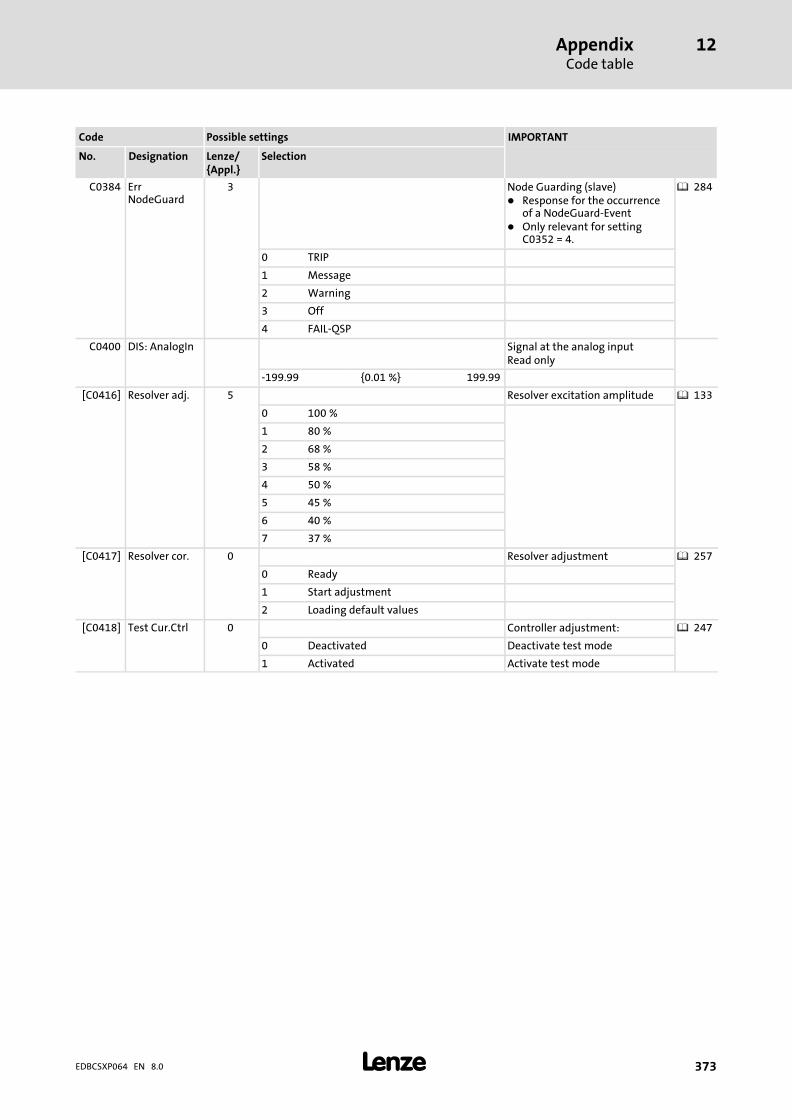
AppendixCode table
12
� 373EDBCSXP064 EN 8.0
IMPORTANTPossible settingsCode
SelectionLenze/{Appl.}
DesignationNo.
C0384 ErrNodeGuard
3 Node Guarding (slave)� Response for the occurrence
of a NodeGuard−Event� Only relevant for setting
C0352 = 4.
� 284
0 TRIP
1 Message
2 Warning
3 Off
4 FAIL−QSP
C0400 DIS: AnalogIn Signal at the analog inputRead only
−199.99 {0.01 %} 199.99
[C0416] Resolver adj. 5 Resolver excitation amplitude � 133
0 100 %
1 80 %
2 68 %
3 58 %
4 50 %
5 45 %
6 40 %
7 37 %
[C0417] Resolver cor. 0 Resolver adjustment � 257
0 Ready
1 Start adjustment
2 Loading default values
[C0418] Test Cur.Ctrl 0 Controller adjustment: � 247
0 Deactivated Deactivate test mode
1 Activated Activate test mode
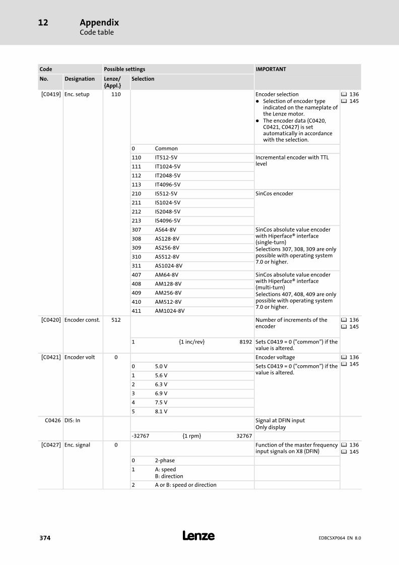
AppendixCode table
12
� 374 EDBCSXP064 EN 8.0
IMPORTANTPossible settingsCode
SelectionLenze/{Appl.}
DesignationNo.
[C0419] Enc. setup 110 Encoder selection� Selection of encoder type
indicated on the nameplate ofthe Lenze motor.
� The encoder data (C0420,C0421, C0427) is setautomatically in accordancewith the selection.
� 136� 145
0 Common
110 IT512−5V Incremental encoder with TTLlevel111 IT1024−5V
112 IT2048−5V
113 IT4096−5V
210 IS512−5V SinCos encoder
211 IS1024−5V
212 IS2048−5V
213 IS4096−5V
307 AS64−8V SinCos absolute value encoderwith Hiperface® interface(single−turn)Selections 307, 308, 309 are onlypossible with operating system7.0 or higher.
308 AS128−8V
309 AS256−8V
310 AS512−8V
311 AS1024−8V
407 AM64−8V SinCos absolute value encoderwith Hiperface® interface(multi−turn)Selections 407, 408, 409 are onlypossible with operating system7.0 or higher.
408 AM128−8V
409 AM256−8V
410 AM512−8V
411 AM1024−8V
[C0420] Encoder const. 512 Number of increments of theencoder
� 136� 145
1 {1 inc/rev} 8192 Sets C0419 = 0 ("common") if thevalue is altered.
[C0421] Encoder volt 0 Encoder voltage � 136� 1450 5.0 V Sets C0419 = 0 ("common") if the
value is altered.1 5.6 V
2 6.3 V
3 6.9 V
4 7.5 V
5 8.1 V
C0426 DIS: In Signal at DFIN inputOnly display
−32767 {1 rpm} 32767
[C0427] Enc. signal 0 Function of the master frequencyinput signals on X8 (DFIN)
� 136� 145
0 2−phase
1 A: speedB: direction
2 A or B: speed or direction
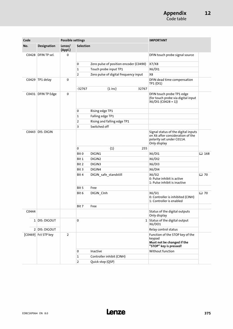
AppendixCode table
12
� 375EDBCSXP064 EN 8.0
IMPORTANTPossible settingsCode
SelectionLenze/{Appl.}
DesignationNo.
C0428 DFIN TP sel. 0 DFIN touch probe signal source
0 Zero pulse of position encoder (C0490) X7/X8
1 Touch probe input TP1 X6/DI1
2 Zero pulse of digital frequency input X8
C0429 TP1 delay 0 DFIN dead time compensationTP1 (DI1)
−32767 {1 inc} 32767
C0431 DFIN TP Edge 0 DFIN touch probe TP1 edge(for touch probe via digital inputX6/DI1 (C0428 = 1))
0 Rising edge TP1
1 Falling edge TP1
2 Rising and falling edge TP1
3 Switched off
C0443 DIS: DIGIN Signal status of the digital inputson X6 after consideration of thepolarity set under C0114.Only display
0 {1} 255
Bit 0 DIGIN1 X6/DI1 � 168
Bit 1 DIGIN2 X6/DI2
Bit 2 DIGIN3 X6/DI3
Bit 3 DIGIN4 X6/DI4
Bit 4 DIGIN_safe_standstill X6/SI20: Pulse inhibit is active1: Pulse inhibit is inactive
� 70
Bit 5 Free
Bit 6 DIGIN_CInh X6/SI10: Controller is inhibited (CINH)1: Controller is enabled
� 70
Bit 7 Free
C0444 Status of the digital outputsOnly display
1 DIS: DIGOUT 0 1 Status of the digital outputX6/DO1
2 DIS: DIGOUT Relay control status
[C0469] Fct STP key 2 Function of the STOP key of thekeypadMust not be changed if the"STOP" key is pressed!
0 Inactive Without function
1 Controller inhibit (CINH)
2 Quick stop (QSP)

AppendixCode table
12
� 376 EDBCSXP064 EN 8.0
IMPORTANTPossible settingsCode
SelectionLenze/{Appl.}
DesignationNo.
C0470 Freely configurable code fordigital signalsHexadecimal value is bit−coded.
1 FCODE 8bit 0 00 {hex} FF C0470/1 = C0471, bit 0 ... 7
2 FCODE 8bit 0 C0470/2 = C0471, bit 8 ... 15
3 FCODE 8bit 0 C0470/3 = C0471, bit 16 ... 23
4 FCODE 8bit 0 C0470/4 = C0471, bit 24 ... 31
C0471 FCODE 32bit 0 Hexadecimal 32−bitinterpretation of C0470
0 {1} 4294967295
C0472 FCODE analog Freely configurable code forrelative analog signals
1 0.0 −199.99 {0.01 %} 199.99 FCODE_bC472_1_a
2 0.0 FCODE_bC472_2_a
3 100.0 FCODE_bC472_3_a
4 0.0 FCODE_bC472_4_a
... ... ...
20 0.0 FCODE_bC472_20_a
C0473 Freely configurable code forabsolute analog signals
1 FCODE abs 1 −32767 {1} 32767
2 FCODE abs 1
3 FCODE abs 0
... ... ...
10 FCODE abs 0
C0474 Freely configurable code forphase signals
1 FCODE PH 0 −2147483647 {1} 2147483647
... ... ...
5 FCODE PH 0
C0475 Freely configurable code forphase difference signals
1 FCODE DF 0 −16000 {1 rpm} 16000
2 FCODE DF 0
[C0490] Feedback pos 0 Selection of feedback system forpositioning control
� 132
0 Resolver at X7 Standard setting
1 TTL encoder at X8 � Sets C0419 = 0 ("Common") ifa different encoder type asunder C0419 is set here.
2 SinCos encoder at X8
3 Absolute value encoder (single−turn) atX8
4 Absolute value encoder (multi−turn) atX8

AppendixCode table
12
� 377EDBCSXP064 EN 8.0
IMPORTANTPossible settingsCode
SelectionLenze/{Appl.}
DesignationNo.
[C0491] X8 in/out 0 Function of X8 � 132
0 X8 is input Use as encoder feedback ormaster frequency input forpositioning profile modeC3095/x = 30 (electrical shaftwith setpoint via X8)
1 X8 is output Use as encoder feedback ormaster frequency output duringmaster operation (electrical shaftas setpoint via X8)
[C0495] Feedback n 0 Selection of feedback system forspeed control
� 132
0 Resolver at X7 Standard setting
1 TTL encoder at X8 � Sets C0419 = 0 ("Common") ifa different encoder type asunder C0419 is set here.
2 SinCos encoder at X8
3 Absolute value encoder (single−turn) atX8
4 Absolute value encoder (multi−turn) atX8
C0497 Nact filter 2.0 Time constant of actual speedvalue
0.0 {0.1 ms} 50.0 0.0 ms = switched off
C0504 Service codes Only the Lenze service is allowedto make changes!...
C0509
C0510 ProtAppFlash 0 Write−protection applicationFLASH
0 No write protection
1 Write protection is active
C0517 User menu with up to 32 entries
1 User menu 51.0 C0051 MCTRL−NACT Display of actual speed
2 User menu 54.0 C0054 Imot Display of motor current
3 User menu(Posi & Shaft)
56.0 C0056 MCTRL−MSET2 Torque setpoint (nMSetIn_a)
{3998.0} C3998 Current fault Current application fault
4 User menu(Posi & Shaft)
0.0{183.0}
C0183 Diagnostics
5 User menu(Posi & Shaft)
0.0{4166.0}
C4166 TripAppReset
6 User menu(Posi & Shaft)
183.0{2113.0}
C2113 PLC prog name
7 User menu(Posi & Shaft)
168.01{22.0}
C0022 Imax current Input of maximum outputcurrent
8 User menu(Posi & Shaft)
0.0{11.0}
C0011 Nmax Input of the maximum speed
9 User menu(Posi & Shaft)
22.0{105.0}
C0105 QSP Tif Entry of deceleration time forquick stop (QSP)
10 User menu(Posi & Shaft)
0.0{70.0}
C0070 Vp speed CTRL Input of gain for speed controller
11 User menu(Posi & Shaft)
11.0{71.0}
C0071 Tn speed CTRL Input of integral−action time forspeed controller
12 User menu(Posi & Shaft)
0.0{254.0}
C0254 Vpw MCTRL_MotorControl: phasecontroller gain (Vp)

AppendixCode table
12
� 378 EDBCSXP064 EN 8.0
IMPORTANTPossible settingsCode
SelectionLenze/{Appl.}
DesignationNo.
13 User menu 0.0 Not assigned
14 User menu 105.0 C0105 QSP Tif Entry of deceleration time forquick stop (QSP)
15 User menu 0.0 Not assigned
16 User menu 70.0 C0070 Vp speed CTRL Input of gain for speed controller
17 User menu 71.0 C0071 Tn speed CTRL Input of integral−action time forspeed controller
18 User menu 0.0 Not assigned
19 User menu 2100.0 C2100 Time slice Input of time slice for cyclic task
20 User menu 2102.0 C2102 Task switch Selection of switch function forcyclic task
21 User menu 2104.0 C2104 PLC autorun Automatic start of PLC programafter power−up
22 User menu 2106.0 C2106 Download protect Write protection of PLC program
23 User menu 2108.0 C2108 PLC run/stop PLC program control
24 User menu 2111.0 C2111 GDC ID Creation date of PLC applicationprogram
25 User menu 2113.0 C2113 PLC prog name Name of PLC applicationprogram
26 User menu 2115.0 C2115 T−Fct credit Number of technology units
27 User menu 0.0 Not assigned
28 User menu 0.0 Not assigned
29 User menu 0.0 Not assigned
30 User menu 0.0 Not assigned
31 User menu 94.0 C0094 Password
32 User menu 3.0 C0003 Par save Save parameter set
0.00 {0.01} 7999.00 � Enter the numbers of therequired codes into thesubcodes.
� Entry in the format xxxx.yy– xxxx = code number– yy = subcode of the code
� It is not checked whether thecode entered exists.
[C0540] X8 Signal out 2 Function of the digital frequencyoutput signals at X8 (DFOUT)
� 87� 136� 1450 Reserved
1 Profile generator output �DFOUT
2 Encoder simulation + zero pulse �DFOUT
C0545 PH offset 0 Phase offset
0 {1 inc} 65535 1 revolution = 65535 increments
C0547 DIS: AN−IN Analog signal on the input of theDFOUT blockRead only
−199.99 {0.00 %} 199.99
C0549 DIS: DF−IN Speed on the input of the DFOUTblockOnly display
−32767 {1 rpm} 32767
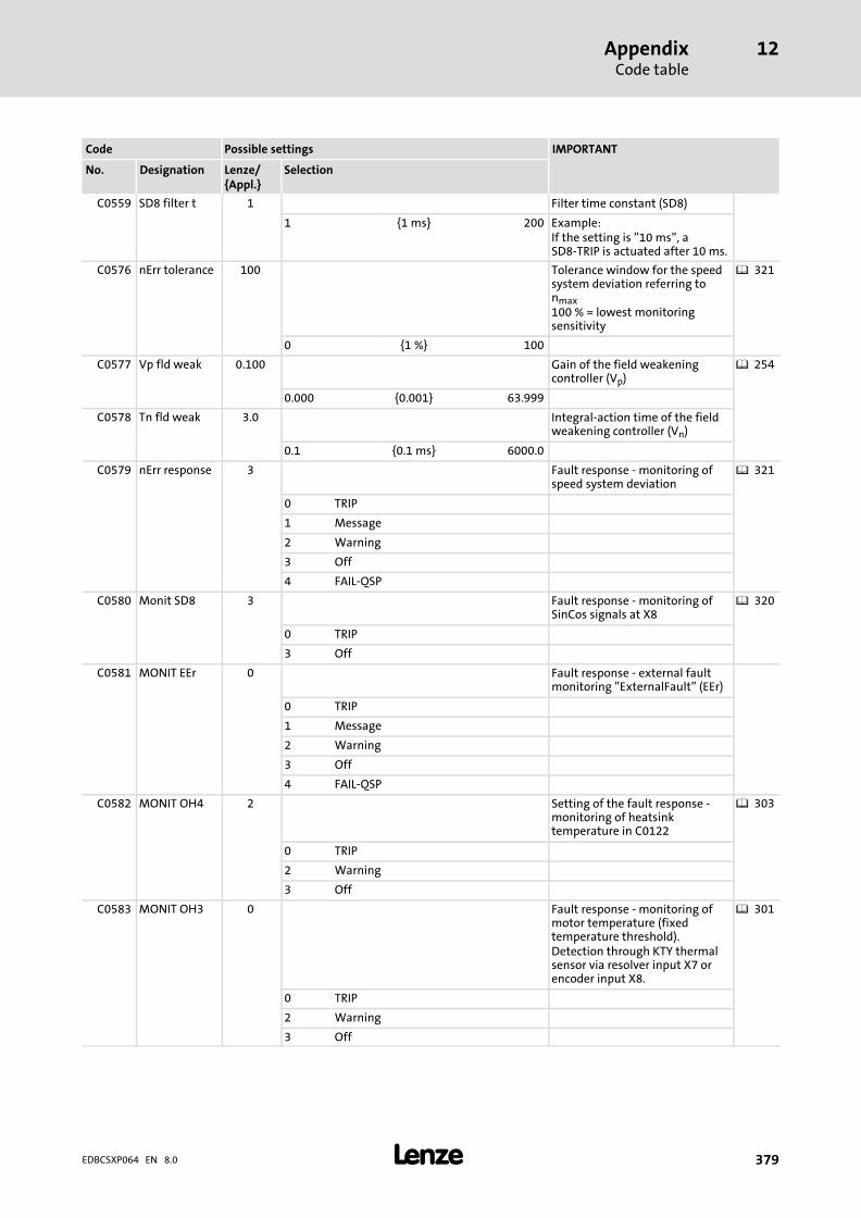
AppendixCode table
12
� 379EDBCSXP064 EN 8.0
IMPORTANTPossible settingsCode
SelectionLenze/{Appl.}
DesignationNo.
C0559 SD8 filter t 1 Filter time constant (SD8)
1 {1 ms} 200 Example:If the setting is "10 ms", aSD8−TRIP is actuated after 10 ms.
C0576 nErr tolerance 100 Tolerance window for the speedsystem deviation referring tonmax100 % = lowest monitoringsensitivity
� 321
0 {1 %} 100
C0577 Vp fld weak 0.100 Gain of the field weakeningcontroller (Vp)
� 254
0.000 {0.001} 63.999
C0578 Tn fld weak 3.0 Integral−action time of the fieldweakening controller (Vn)
0.1 {0.1 ms} 6000.0
C0579 nErr response 3 Fault response − monitoring ofspeed system deviation
� 321
0 TRIP
1 Message
2 Warning
3 Off
4 FAIL−QSP
C0580 Monit SD8 3 Fault response − monitoring ofSinCos signals at X8
� 320
0 TRIP
3 Off
C0581 MONIT EEr 0 Fault response − external faultmonitoring "ExternalFault" (EEr)
0 TRIP
1 Message
2 Warning
3 Off
4 FAIL−QSP
C0582 MONIT OH4 2 Setting of the fault response −monitoring of heatsinktemperature in C0122
� 303
0 TRIP
2 Warning
3 Off
C0583 MONIT OH3 0 Fault response − monitoring ofmotor temperature (fixedtemperature threshold).Detection through KTY thermalsensor via resolver input X7 orencoder input X8.
� 301
0 TRIP
2 Warning
3 Off

AppendixCode table
12
� 380 EDBCSXP064 EN 8.0
IMPORTANTPossible settingsCode
SelectionLenze/{Appl.}
DesignationNo.
C0584 MONIT OH7 2 Fault response − motortemperature monitoringTemperature threshold can beset under C0121.Detection through KTY thermalsensor via resolver input X7 orencoder input X8.Only effective if OH3 is switchedon under C0583.
� 301
0 TRIP
2 Warning
3 Off
C0586 MONIT SD2 0 Fault response − monitoringResolver "ResolverFault" (Sd2)
� 317
0 TRIP
2 Warning
3 Off
C0588 MONITH10/H11
0 Fault response − monitoringThermal sensors in thecontroller.H10: Sensor inside the deviceH11: Heatsink sensor
� 305
0 TRIP
2 Warning
3 Off
C0591 MONIT CE1 3 Fault response − monitoringCAN1_IN (no telegrams)"CommErrCANIN1" (CE1)
� 297
0 TRIP
2 Warning
3 Off
C0592 MONIT CE2 3 Fault response − monitoringCAN2_IN (no telegrams)"CommErrCANIN2" (CE2)
� 297
0 TRIP
2 Warning
3 Off
C0593 MONIT CE3 3 Fault response − monitoringCAN3_IN (no telegrams)"CommErrCANIN3" (CE3)
� 297
0 TRIP
2 Warning
3 Off
C0594 MONIT SD6 3 Fault response − monitoringKTY sensor for the motortemperature."SensorFault" (Sd6)
� 318
0 TRIP
2 Warning
3 Off
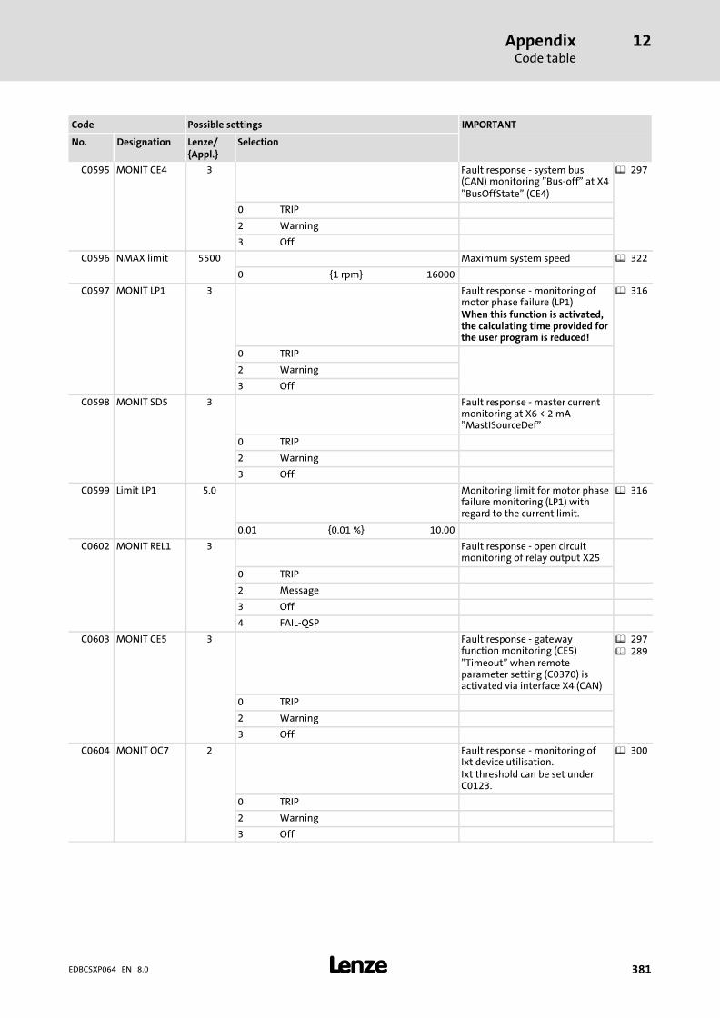
AppendixCode table
12
� 381EDBCSXP064 EN 8.0
IMPORTANTPossible settingsCode
SelectionLenze/{Appl.}
DesignationNo.
C0595 MONIT CE4 3 Fault response − system bus(CAN) monitoring "Bus−off" at X4"BusOffState" (CE4)
� 297
0 TRIP
2 Warning
3 Off
C0596 NMAX limit 5500 Maximum system speed � 322
0 {1 rpm} 16000
C0597 MONIT LP1 3 Fault response − monitoring ofmotor phase failure (LP1)When this function is activated,the calculating time provided forthe user program is reduced!
� 316
0 TRIP
2 Warning
3 Off
C0598 MONIT SD5 3 Fault response − master currentmonitoring at X6 < 2 mA"MastISourceDef"
0 TRIP
2 Warning
3 Off
C0599 Limit LP1 5.0 Monitoring limit for motor phasefailure monitoring (LP1) withregard to the current limit.
� 316
0.01 {0.01 %} 10.00
C0602 MONIT REL1 3 Fault response − open circuitmonitoring of relay output X25
0 TRIP
2 Message
3 Off
4 FAIL−QSP
C0603 MONIT CE5 3 Fault response − gatewayfunction monitoring (CE5)"Timeout" when remoteparameter setting (C0370) isactivated via interface X4 (CAN)
� 297� 289
0 TRIP
2 Warning
3 Off
C0604 MONIT OC7 2 Fault response − monitoring ofIxt device utilisation.Ixt threshold can be set underC0123.
� 300
0 TRIP
2 Warning
3 Off

AppendixCode table
12
� 382 EDBCSXP064 EN 8.0
IMPORTANTPossible settingsCode
SelectionLenze/{Appl.}
DesignationNo.
C0605 MONIT OH5 2 Fault response − monitoring oftemperature inside thecontroller.Temperature threshold can beset under C0124.
� 304
0 TRIP
2 Warning
3 Off
C0606 MONIT OC8 2 Fault response − monitoring ofI2 x t motor utilisation.Threshold can be set underC0120.
� 309
0 TRIP
2 Warning
3 Off
C0607 MONIT NMAX 0 Fault response − maximum speedmonitoring of the machine
0 TRIP
2 Warning
3 Off
C0608 ovr. Tx−Queue 2 Fault response − transmissionmemory overflow of free CANobjects
0 TRIP
1 Message
2 Warning
3 Off
4 FAIL−QSP
C0609 ovr. Rx−Isr 0 Fault response Receive memoryoverflow of free CAN objects
0 TRIP
4 FAIL−QSP
C0855 Digital process data input wordsare indicated on the AIF interface(AIF1_IN)Hexadecimal value is bit−coded.Read only
1 AIF1 IN bits 0000 {hex} FFFF Input word 2 (bit 0 ... 15)
2 AIF1 IN bits Input word 3 (bit 0 ... 15)
C0856 Analog process data input wordsare indicated decimally on theAIF interface (AIF1_IN)100.00% = 16384Read only
1 AIF1 IN words −199.99 {0.01 %} 199.99 Input word 1
2 AIF1 IN words Input word 2
3 AIF1 IN words Input word 3
C0857 AIF1 IN phi 32 bits of phase information onthe AIF interface (AIF1_IN)Read only
−2147483648 {1} 2147483647

AppendixCode table
12
� 383EDBCSXP064 EN 8.0
IMPORTANTPossible settingsCode
SelectionLenze/{Appl.}
DesignationNo.
C0858 Analog process data outputwords are indicated decimally onthe AIF interface (AIF1_OUT)100.00% = 16384Read only
1 AIF1 OUTwords
−199.99 {0.01 %} 199.99 Output word 1
2 AIF1 OUTwords
Output word 2
3 AIF1 OUTwords
Output word 3
C0859 AIF1 OUT phi 32−bit phase information at theAIF interface (AIF1_OUT)Only display
−2147483648 {1} 2147483647
C0863 Digital process data input wordsfor CAN bus interface X4Hexadecimal value is bit−coded.Read only
� 418
0000 {hex} FFFF
1 CAN IN bits Bit 0 ... Bit15 CAN1_IN: Process data inputword 1
2 CAN IN bits Bit 16 ... Bit 31 CAN1_IN: Process data inputword 2
3 CAN IN bits Bit 0 ... Bit15 CAN2_IN: Process data inputword 1
4 CAN IN bits Bit 16 ... Bit 31 CAN2_IN: Process data inputword 2
5 CAN IN bits Bit 0 ... Bit15 CAN3_IN: Process data inputword 1
6 CAN IN bits Bit 16 ... Bit 31 CAN3_IN: Process data inputword 2
C0866 Analog process data input words(decimal) for CAN bus interfaceX4100.00% = 16384Read only
� 418
1 CAN IN words −199.99 {0.01 %} 199.99 CAN1_IN word 1
2 CAN IN words CAN1_IN word 2
3 CAN IN words CAN1_IN word 3
4 CAN IN words CAN2_IN word 1
5 CAN IN words CAN2_IN word 2
6 CAN IN words CAN2_IN word 3
7 CAN IN words CAN2_IN word 4
8 CAN IN words CAN3_IN word 1
9 CAN IN words CAN3_IN word 2
10 CAN IN words CAN3_IN word 3
11 CAN IN words CAN3_IN word 4
C0867 32−bit phase information forCAN bus interface X4Read only
1 CAN IN phi −2147483648 {1} 2147483647 CAN1_IN
2 CAN IN phi CAN2_IN
3 CAN IN phi CAN3_IN
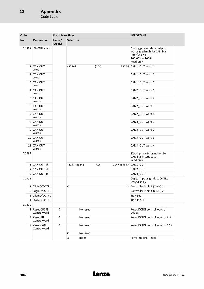
AppendixCode table
12
� 384 EDBCSXP064 EN 8.0
IMPORTANTPossible settingsCode
SelectionLenze/{Appl.}
DesignationNo.
C0868 DIS:OUTx.Wx Analog process data outputwords (decimal) for CAN businterface X4100.00% = 16384Read only
1 CAN OUTwords
−32768 {1 %} 32768 CAN1_OUT word 1
2 CAN OUTwords
CAN1_OUT word 2
3 CAN OUTwords
CAN1_OUT word 3
4 CAN OUTwords
CAN2_OUT word 1
5 CAN OUTwords
CAN2_OUT word 2
6 CAN OUTwords
CAN2_OUT word 3
7 CAN OUTwords
CAN2_OUT word 4
8 CAN OUTwords
CAN3_OUT word 1
9 CAN OUTwords
CAN3_OUT word 2
10 CAN OUTwords
CAN3_OUT word 3
11 CAN OUTwords
CAN3_OUT word 4
C0869 32−bit phase information forCAN bus interface X4Read only
1 CAN OUT phi −2147483648 {1} 2147483647 CAN1_OUT
2 CAN OUT phi CAN2_OUT
3 CAN OUT phi CAN3_OUT
C0878 Digital input signals to DCTRLOnly display
1 DigInOfDCTRL 0 1 Controller inhibit (CINH) 1
2 DigInOfDCTRL Controller inhibit (CINH) 2
3 DigInOfDCTRL TRIP−set
4 DigInOfDCTRL TRIP−RESET
C0879
1 Reset C0135Controlword
0 No reset Reset DCTRL control word ofC0135
2 Reset AIFControlword
0 No reset Reset DCTRL control word of AIF
3 Reset CANControlword
0 No reset Reset DCTRL control word of CAN
0 No reset
1 Reset Performs one "reset"

AppendixCode table
12
� 385EDBCSXP064 EN 8.0
IMPORTANTPossible settingsCode
SelectionLenze/{Appl.}
DesignationNo.
C0906 Analog input signals to MCTRLRead only
1 MCTRL analog −199.99 {0.01 %} 199.99 Speed controller input
2 MCTRL analog Torque setpoint
3 MCTRL analog Lower torque limit
4 MCTRL analog Upper torque limit
5 MCTRL analog Limit of the position controller
6 MCTRL analog Speed for activating the torquelimitation
7 MCTRL analog Field weakening
8 MCTRL analog Integrator of the speed controller
9 MCTRL analog P adaptation of the positioncontroller
C0907 Digital input signals to MCTRLOnly display
1 MCTRL digital 0 1 Activating position controller
2 MCTRL digital Speed control or torque control
3 MCTRL digital Set quick stop (QSP)
4 MCTRL digital Loading integral−actioncomponent of the speedcontroller
C0908 MCTRL PosSet Set phase signal1 revolution = 65536 incrementsOnly display
−2147483648 {1 inc} 2147483647
C0909 speed limit 1 Limitation of direction ofrotation for speed setpoint
1 −175 ... +175 %
2 0 ... +175 %
3 −175 ... 0 %
C0910 MCTRL TP2delay
0 MCTRL dead time compensationTP2 (X6/DI2)
−32767 {1 inc} 32767 1 inc � approx. 60 �s
C0911 MCTRL TP2sel.
0 MCTRL touch probe signal source
0 Zero pulse of position encoder (C0490) X7/X8
1 Touch probe input TP2 X6/DI2
C0912 MCTRL TP2Edge
0 MCTRL touch probe TP2 edge(for touch probe via digital inputX6/DI2 (C0911 = 1))
0 Rising edge TP2
1 Falling edge TP2
2 Rising and falling edge TP2
3 Switched off
C1120 Sync mode 0 Sync signal source � 278
0 Off Off
1 CAN sync Sync connection via interface X4(CAN)
� 282
2 Terminal sync Sync connection via terminalX6/DI1
� 283

AppendixCode table
12
� 386 EDBCSXP064 EN 8.0
IMPORTANTPossible settingsCode
SelectionLenze/{Appl.}
DesignationNo.
C1121 Sync cycle 2 Synchronisation cycle � 278
1 {1 ms} 13
C1122 Sync phase 0.460 Synchronisation phase � 278
0.000 {0.001 ms} 6.500
C1123 Sync window 0.010 Synchronisation window� When the sync
telegram/signal transmittedby the master is within this"time slot", the status bitStat2.CANSyncInWin switchesto TRUE.
0.000 {0.001 ms} 6.500
C1190 MPTC mode 0 Selection of PTC motortemperature sensorcharacteristic
0 Characteristic for PTC 83−110 (Lenzestandard)
1 Can be specifically set by the userunder C1191 and C1192
2 Characteristic for PTC 83−110 and 2 xPTC150 (e.g. in MCS motors)
This selection is only available asof operating system V 8.0. Forthe corresponding motors, theparameter is not automaticallytransferred into GDC by themotor data assistant. Theparameter has to be set later!
C1191 Selection of temperaturecharacteristic for PTC
1 Char.: temp 25 0 {1 °C} 255 PTC characteristic: lower temperature T1
2 Char.: temp 150 PTC characteristic: upper temperature T2
C1192 Selection of resistancecharacteristic for PTC
1 Char.: OHM 1000{0}
0 {1 �} 30000 PTC characteristic: resistance R1 at T1
2 Char.: OHM 2225 PTC characteristic: resistance R2 at T2
C1200 Fdbk rat num 1 Feedback of gearbox factornumerator� The gearbox ratio (i) specifies
the number of revolutions ofthe motor axis at which theencoder axis revolves exactlyonce.
� i = Z2 / Z1 (ratio of thenumber of teeth orcircumferences)
� i = n1 / n2 (ratio of thespeeds)
1 {1} 65535
C1201 Fdbk rat den 1 Feedback of gearbox factordenominator
1 {1} 65535

AppendixCode table
12
� 387EDBCSXP064 EN 8.0
IMPORTANTPossible settingsCode
SelectionLenze/{Appl.}
DesignationNo.
C1202 Gear num 1 Gearbox factor numeratorThe gearbox ratio specifies thenumber of revolutions of themotor axis at which the loadrevolves exactly once.� i = Z2 / Z1 (ratio of the
number of teeth orcircumferences)
� i = n1 / n2 (ratio of thespeeds)
� 103
1 {1} 65535
C1203 Gear denom 1 Gearbox factor denominator � 103
1 {1} 65535
C1204 Feed const 360.0 The feed constant specifies thepath (in units) which the load(slide) covers in one revolution.
� 103
0.0001 {0.0001units/rev}
214000.0000
C1240 Vel_max 18000.0 Max. permissible speed of theload (slide).Note: Enter the motor speedresulting from Vel_max plus 10%reserve in C0011!
� 103
0.0001 {0.0001units/s}
214000.0000
C1250 Acc_max 36000.0 Max. accelerationNote: This parameter amongother things depends on themotor torque and the momentof inertia of the entire mechanicsdriven during the positioningprocess!
� 103
0.0001 {0.0001units/s2}
214000.0000
C1256 S−RMP: Jerk 1.0 The max. jerk is definedaccording to a selected time(tjerk_max) after which the max.acceleration (amax) is reached.Note:If disproportionately high S−ramptimes (jerk times) are set forshort accelerating times, theprofile may be generatedincorrectly!
0.000 {0.001 s} 10.000
C1810 SW ID LECOM Software identification LECOMOnly display
C1811 SW dateLECOM
Software creation date LECOMOnly display
C2100 Time slice 13 Time slice for cyclic task
6 {1 ms} 26
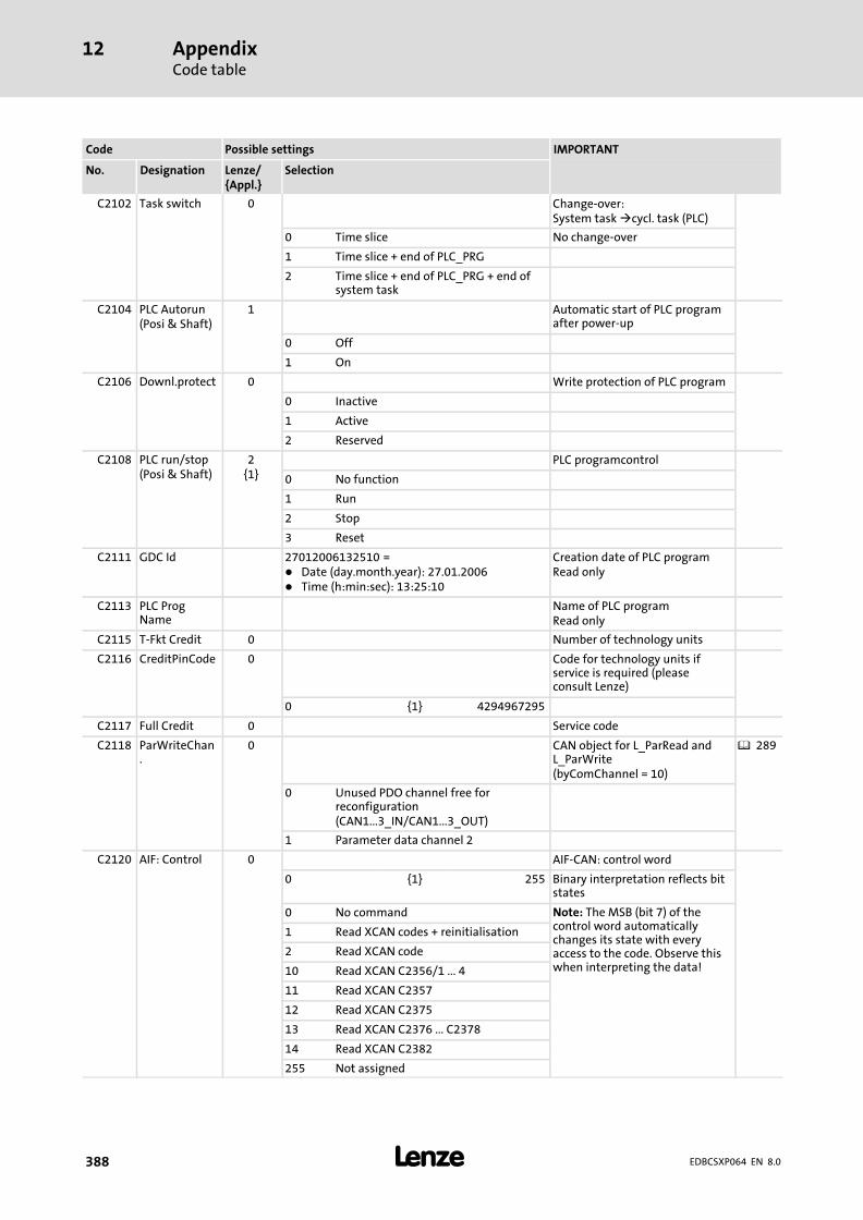
AppendixCode table
12
� 388 EDBCSXP064 EN 8.0
IMPORTANTPossible settingsCode
SelectionLenze/{Appl.}
DesignationNo.
C2102 Task switch 0 Change−over:System task �cycl. task (PLC)
0 Time slice No change−over
1 Time slice + end of PLC_PRG
2 Time slice + end of PLC_PRG + end ofsystem task
C2104 PLC Autorun(Posi & Shaft)
1 Automatic start of PLC programafter power−up
0 Off
1 On
C2106 Downl.protect 0 Write protection of PLC program
0 Inactive
1 Active
2 Reserved
C2108 PLC run/stop(Posi & Shaft)
2{1}
PLC programcontrol
0 No function
1 Run
2 Stop
3 Reset
C2111 GDC Id 27012006132510 =� Date (day.month.year): 27.01.2006� Time (h:min:sec): 13:25:10
Creation date of PLC programRead only
C2113 PLC ProgName
Name of PLC programRead only
C2115 T−Fkt Credit 0 Number of technology units
C2116 CreditPinCode 0 Code for technology units ifservice is required (pleaseconsult Lenze)
0 {1} 4294967295
C2117 Full Credit 0 Service code
C2118 ParWriteChan.
0 CAN object for L_ParRead andL_ParWrite(byComChannel = 10)
� 289
0 Unused PDO channel free forreconfiguration(CAN1...3_IN/CAN1...3_OUT)
1 Parameter data channel 2
C2120 AIF: Control 0 AIF−CAN: control word
0 {1} 255 Binary interpretation reflects bitstates
0 No command Note: The MSB (bit 7) of thecontrol word automaticallychanges its state with everyaccess to the code. Observe thiswhen interpreting the data!
1 Read XCAN codes + reinitialisation
2 Read XCAN code
10 Read XCAN C2356/1 ... 4
11 Read XCAN C2357
12 Read XCAN C2375
13 Read XCAN C2376 ... C2378
14 Read XCAN C2382
255 Not assigned

AppendixCode table
12
� 389EDBCSXP064 EN 8.0
IMPORTANTPossible settingsCode
SelectionLenze/{Appl.}
DesignationNo.
C2121 AIF:State AIF statusMore detailed information canbe found in the documentationof the plugged−in fieldbusmodule.Read only
1 {1} 255 Binary interpretation reflects bitstates.
Bit 0 XCAN1_IN monitoring time
Bit 1 XCAN2_IN monitoring time
Bit2 XCAN3_IN monitoring time
Bit3 XCAN bus off
Bit4 XCAN operational
Bit5 XCAN pre−operational
Bit 6 XCAN warning
Bit 7 Assigned internally
C2130 FileNameAddDa
Symbolic data name Information on the additionaldata that have been transmittedtogether with the applicationprogram.Only display
C2131 Type AddData Specification identification of the data
C2132 VersionAddData
Data version
C2133 TimeStamp Time stamp of the data
C2350 XCAN address 1 Node address XCAN(AIF interface X1)
1 {1} 63
C2351 XCAN baudrate
0 Baud rate XCAN(AIF interface X1)
0 500 kbps
1 250 kbit/sec
2 125 kbits/s
3 50 kbps
4 1000 kbit/s
C2352 XCAN mst 0 Establish XCAN masteroperation.(AIF interface X1)
0 Slave
1 Master
C2353 Source for system bus nodeaddresses ofXCAN_IN/XCAN_OUT(AIF interface X1)
1 XCAN addr sel 0 CAN node address (C2350) XCAN1_IN/OUTaddress
2 XCAN addr sel 0 CAN node address (C2350) XCAN2_IN/OUTaddress
3 XCAN addr sel 0 CAN node address (C2350) XCAN3_IN/OUTaddress
0 C2350 (auto) Automatically determined byC2350
1 C2354 (man.) Determined by C2354
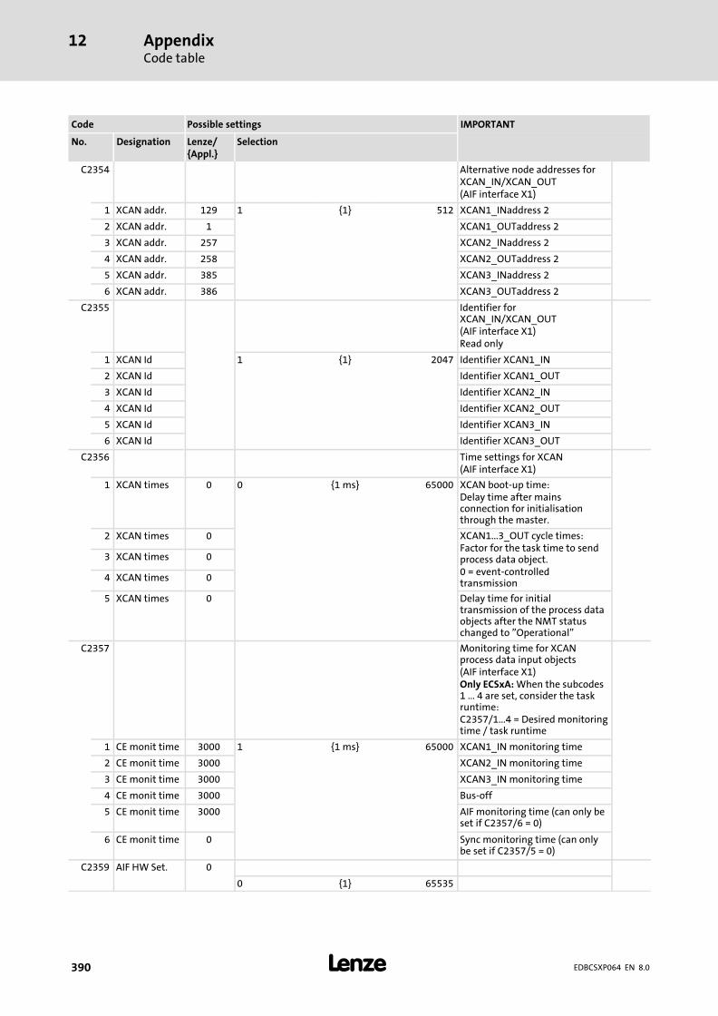
AppendixCode table
12
� 390 EDBCSXP064 EN 8.0
IMPORTANTPossible settingsCode
SelectionLenze/{Appl.}
DesignationNo.
C2354 Alternative node addresses forXCAN_IN/XCAN_OUT(AIF interface X1)
1 XCAN addr. 129 1 {1} 512 XCAN1_INaddress 2
2 XCAN addr. 1 XCAN1_OUTaddress 2
3 XCAN addr. 257 XCAN2_INaddress 2
4 XCAN addr. 258 XCAN2_OUTaddress 2
5 XCAN addr. 385 XCAN3_INaddress 2
6 XCAN addr. 386 XCAN3_OUTaddress 2
C2355 Identifier forXCAN_IN/XCAN_OUT(AIF interface X1)Read only
1 XCAN Id 1 {1} 2047 Identifier XCAN1_IN
2 XCAN Id Identifier XCAN1_OUT
3 XCAN Id Identifier XCAN2_IN
4 XCAN Id Identifier XCAN2_OUT
5 XCAN Id Identifier XCAN3_IN
6 XCAN Id Identifier XCAN3_OUT
C2356 Time settings for XCAN(AIF interface X1)
1 XCAN times 0 0 {1 ms} 65000 XCAN boot−up time:Delay time after mainsconnection for initialisationthrough the master.
2 XCAN times 0 XCAN1...3_OUT cycle times:Factor for the task time to sendprocess data object.0 = event−controlledtransmission
3 XCAN times 0
4 XCAN times 0
5 XCAN times 0 Delay time for initialtransmission of the process dataobjects after the NMT statuschanged to "Operational"
C2357 Monitoring time for XCANprocess data input objects(AIF interface X1)Only ECSxA: When the subcodes1 ... 4 are set, consider the taskruntime:C2357/1...4 = Desired monitoringtime / task runtime
1 CE monit time 3000 1 {1 ms} 65000 XCAN1_IN monitoring time
2 CE monit time 3000 XCAN2_IN monitoring time
3 CE monit time 3000 XCAN3_IN monitoring time
4 CE monit time 3000 Bus−off
5 CE monit time 3000 AIF monitoring time (can only beset if C2357/6 = 0)
6 CE monit time 0 Sync monitoring time (can onlybe set if C2357/5 = 0)
C2359 AIF HW Set. 0
0 {1} 65535

AppendixCode table
12
� 391EDBCSXP064 EN 8.0
IMPORTANTPossible settingsCode
SelectionLenze/{Appl.}
DesignationNo.
C2367 Sync Rx Id 128 XCAN receive identifier of thesync telegram(AIF interface X1)
1 {1} 2047
C2368 Sync Tx Id 128 XCAN send identifier of the synctelegram(AIF interface X1)
1 {1} 2047
C2373 XCAN Sync counter(AIF interface X1)
1 Sync Rate IN 1 1 {1} 240 XCAN1_IN
2 Sync Rate IN 1 XCAN2_IN
3 Sync Rate IN 1 XCAN3_IN
C2374 XCAN Sync counter(AIF interface X1)
1 Sync Rate OUT 1 1 {1} 240 XCAN1_OUT
2 Sync Rate OUT 1 XCAN2_OUT
3 Sync Rate OUT 1 XCAN3_OUT
C2375 TX mode for XCANx_OUT(AIF interface X1)
1 XCAN Txmode
0 Response to sync XCAN1_OUT
2 XCAN Txmode
0 Response to sync XCAN2_OUT
3 XCAN Txmode
0 Response to sync XCAN3_OUT
0 Response to sync
1 No response to sync
2 Event
3 Event, cycle C2356 superimposed
C2376 XCAN1_OUT mask(AIF interface X1)
1 XCAN1 Mask FFFF 0000 {hex} FFFF Mask for process data outputword 1
2 XCAN1 Mask FFFF Mask for process data outputword 2
3 XCAN1 Mask FFFF Mask for process data outputword 3
4 XCAN1 Mask FFFF Mask for process data outputword 4
C2377 XCAN2_OUT mask(AIF interface X1)
1 XCAN2 Mask FFFF 0000 {hex} FFFF Mask for process data outputword 1
2 XCAN2 Mask FFFF Mask for process data outputword 2
3 XCAN2 Mask FFFF Mask for process data outputword 3
4 XCAN2 Mask FFFF Mask for process data outputword 4

AppendixCode table
12
� 392 EDBCSXP064 EN 8.0
IMPORTANTPossible settingsCode
SelectionLenze/{Appl.}
DesignationNo.
C2378 XCAN3_OUT mask(AIF interface X1)
1 XCAN3 Mask FFFF 0000 {hex} FFFF Mask for process data outputword 1
2 XCAN3 Mask FFFF Mask for process data outputword 2
3 XCAN3 Mask FFFF Mask for process data outputword 3
4 XCAN3 Mask FFFF Mask for process data outputword 4
C2382 The XCAN monitoring isconfigured if no telegrams havebeen received.(AIF interface X1)
1 XCAN Conf. CE 0 Off XCAN1_IN
2 XCAN Conf. CE 0 Off XCAN2_IN
3 XCAN Conf. CE 0 Off XCAN3_IN
4 XCAN Conf. CE 0 Off Bus−off
5 XCAN Conf. CE 0 Off Life Guarding / Heartbeat Event
6 XCAN Conf. CE 0 Off Response to sync reception
0 Off
1 Controller inhibit (CINH)
2 Quick stop (QSP)
C2450 CANa address 1 Node address for CAN businterface X14 (CAN−AUX)
� 266� 429
1 {1} 63 This code is inactive if one of DIPswitches 2 ... 7 and switch 1 areset to "ON".
C2451 CANa baudrate
0 Baud rate for CAN bus interfaceX14 (CAN−AUX)
� 266
0 500 kBit/s
1 250 kBit/s
2 125 kBit/s
3 50 kBit/s
4 1000 kBit/s
C2452 CANa mst 0 Configuration of master/slavefor CAN bus interface X14(CAN−AUX)
� 273
0 Slave
1 Master
C2453 Source for system bus nodeaddresses ofCANaux_IN/CANaux_OUT (CANbus interface X14)
� 271
1 CANa addr sel 0 CAN node address (C2450) Address CANaux1_IN/OUT
2 CANa addr sel 0 CAN node address (C2450) Address CANaux2_IN/OUT
3 CANa addr sel 0 CAN node address (C2450) Address CANaux3_IN/OUT
0 C2450 (auto) Automatically determined byC2450
1 C2454 (man.) Determined by C2454
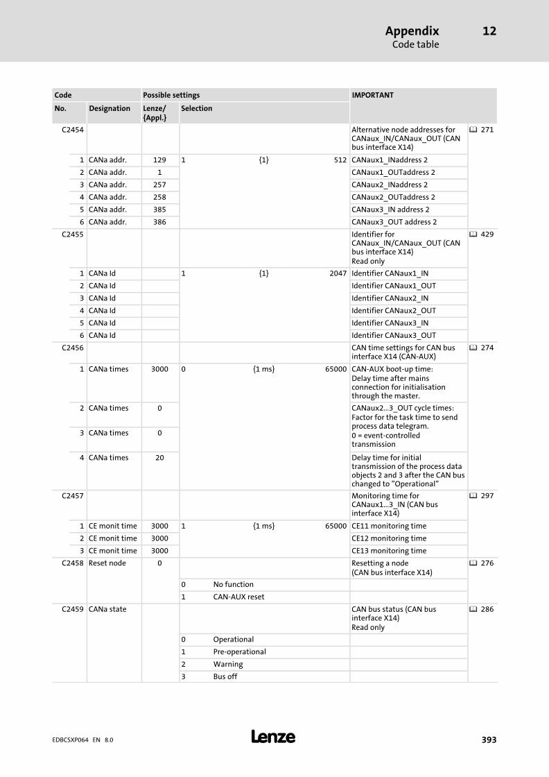
AppendixCode table
12
� 393EDBCSXP064 EN 8.0
IMPORTANTPossible settingsCode
SelectionLenze/{Appl.}
DesignationNo.
C2454 Alternative node addresses forCANaux_IN/CANaux_OUT (CANbus interface X14)
� 271
1 CANa addr. 129 1 {1} 512 CANaux1_INaddress 2
2 CANa addr. 1 CANaux1_OUTaddress 2
3 CANa addr. 257 CANaux2_INaddress 2
4 CANa addr. 258 CANaux2_OUTaddress 2
5 CANa addr. 385 CANaux3_IN address 2
6 CANa addr. 386 CANaux3_OUT address 2
C2455 Identifier forCANaux_IN/CANaux_OUT (CANbus interface X14)Read only
� 429
1 CANa Id 1 {1} 2047 Identifier CANaux1_IN
2 CANa Id Identifier CANaux1_OUT
3 CANa Id Identifier CANaux2_IN
4 CANa Id Identifier CANaux2_OUT
5 CANa Id Identifier CANaux3_IN
6 CANa Id Identifier CANaux3_OUT
C2456 CAN time settings for CAN businterface X14 (CAN−AUX)
� 274
1 CANa times 3000 0 {1 ms} 65000 CAN−AUX boot−up time:Delay time after mainsconnection for initialisationthrough the master.
2 CANa times 0 CANaux2...3_OUT cycle times:Factor for the task time to sendprocess data telegram.0 = event−controlledtransmission
3 CANa times 0
4 CANa times 20 Delay time for initialtransmission of the process dataobjects 2 and 3 after the CAN buschanged to "Operational"
C2457 Monitoring time forCANaux1...3_IN (CAN businterface X14)
� 297
1 CE monit time 3000 1 {1 ms} 65000 CE11 monitoring time
2 CE monit time 3000 CE12 monitoring time
3 CE monit time 3000 CE13 monitoring time
C2458 Reset node 0 Resetting a node(CAN bus interface X14)
� 276
0 No function
1 CAN−AUX reset
C2459 CANa state CAN bus status (CAN businterface X14)Read only
� 286
0 Operational
1 Pre−operational
2 Warning
3 Bus off
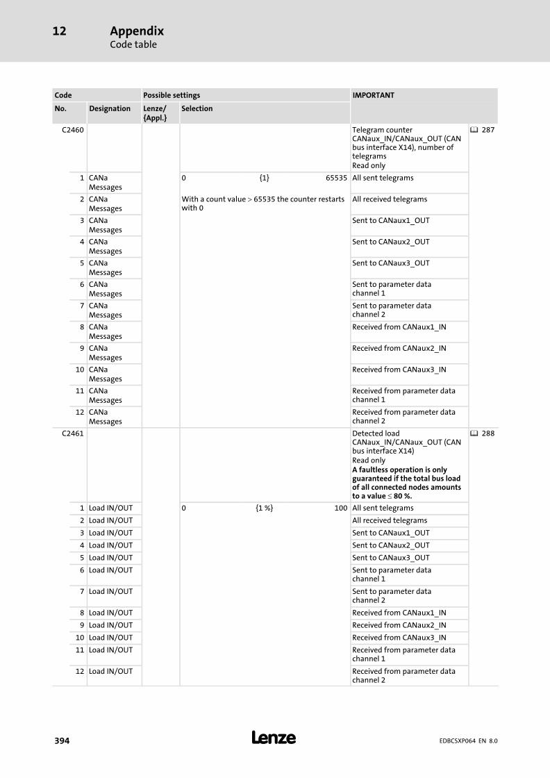
AppendixCode table
12
� 394 EDBCSXP064 EN 8.0
IMPORTANTPossible settingsCode
SelectionLenze/{Appl.}
DesignationNo.
C2460 Telegram counterCANaux_IN/CANaux_OUT (CANbus interface X14), number oftelegramsRead only
� 287
1 CANaMessages
0 {1} 65535 All sent telegrams
2 CANaMessages
With a count value � 65535 the counter restartswith 0
All received telegrams
3 CANaMessages
Sent to CANaux1_OUT
4 CANaMessages
Sent to CANaux2_OUT
5 CANaMessages
Sent to CANaux3_OUT
6 CANaMessages
Sent to parameter datachannel 1
7 CANaMessages
Sent to parameter datachannel 2
8 CANaMessages
Received from CANaux1_IN
9 CANaMessages
Received from CANaux2_IN
10 CANaMessages
Received from CANaux3_IN
11 CANaMessages
Received from parameter datachannel 1
12 CANaMessages
Received from parameter datachannel 2
C2461 Detected loadCANaux_IN/CANaux_OUT (CANbus interface X14)Read onlyA faultless operation is onlyguaranteed if the total bus loadof all connected nodes amountsto a value � 80 %.
� 288
1 Load IN/OUT 0 {1 %} 100 All sent telegrams
2 Load IN/OUT All received telegrams
3 Load IN/OUT Sent to CANaux1_OUT
4 Load IN/OUT Sent to CANaux2_OUT
5 Load IN/OUT Sent to CANaux3_OUT
6 Load IN/OUT Sent to parameter datachannel 1
7 Load IN/OUT Sent to parameter datachannel 2
8 Load IN/OUT Received from CANaux1_IN
9 Load IN/OUT Received from CANaux2_IN
10 Load IN/OUT Received from CANaux3_IN
11 Load IN/OUT Received from parameter datachannel 1
12 Load IN/OUT Received from parameter datachannel 2
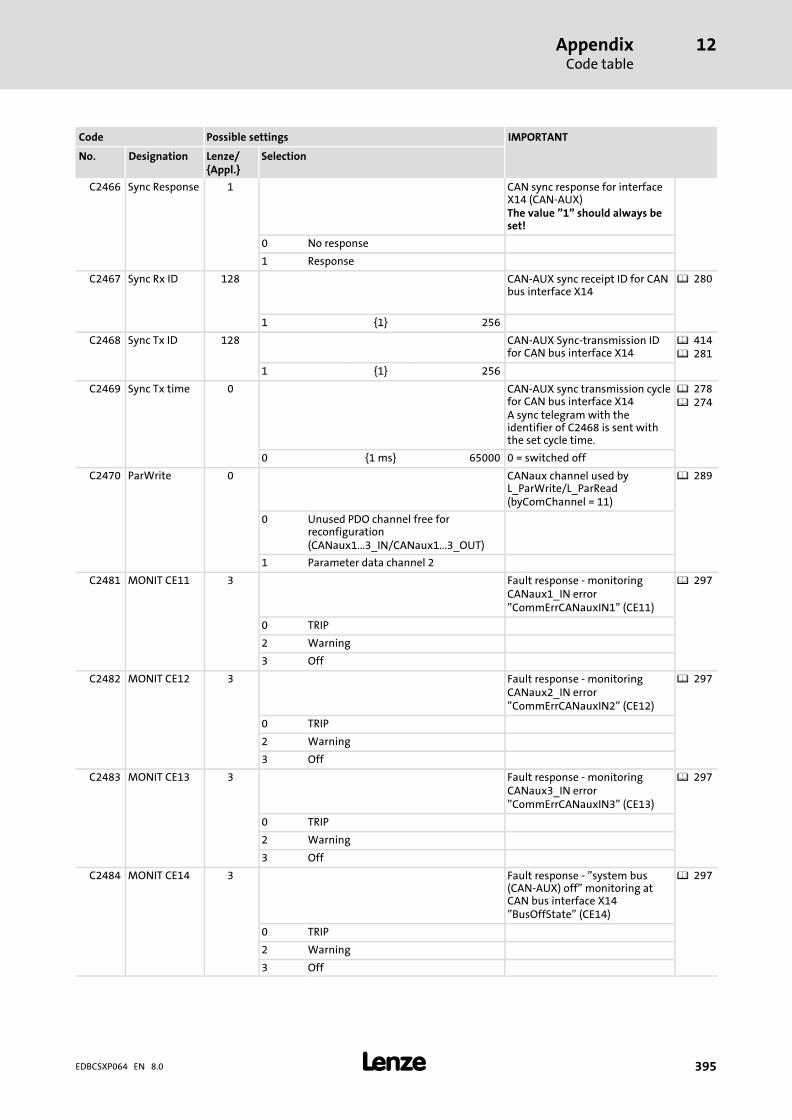
AppendixCode table
12
� 395EDBCSXP064 EN 8.0
IMPORTANTPossible settingsCode
SelectionLenze/{Appl.}
DesignationNo.
C2466 Sync Response 1 CAN sync response for interfaceX14 (CAN−AUX)The value "1" should always beset!
0 No response
1 Response
C2467 Sync Rx ID 128 CAN−AUX sync receipt ID for CANbus interface X14
� 280
1 {1} 256
C2468 Sync Tx ID 128 CAN−AUX Sync−transmission IDfor CAN bus interface X14
� 414� 281
1 {1} 256
C2469 Sync Tx time 0 CAN−AUX sync transmission cyclefor CAN bus interface X14A sync telegram with theidentifier of C2468 is sent withthe set cycle time.
� 278� 274
0 {1 ms} 65000 0 = switched off
C2470 ParWrite 0 CANaux channel used byL_ParWrite/L_ParRead(byComChannel = 11)
� 289
0 Unused PDO channel free forreconfiguration(CANaux1...3_IN/CANaux1...3_OUT)
1 Parameter data channel 2
C2481 MONIT CE11 3 Fault response − monitoringCANaux1_IN error"CommErrCANauxIN1" (CE11)
� 297
0 TRIP
2 Warning
3 Off
C2482 MONIT CE12 3 Fault response − monitoringCANaux2_IN error"CommErrCANauxIN2" (CE12)
� 297
0 TRIP
2 Warning
3 Off
C2483 MONIT CE13 3 Fault response − monitoringCANaux3_IN error"CommErrCANauxIN3" (CE13)
� 297
0 TRIP
2 Warning
3 Off
C2484 MONIT CE14 3 Fault response − "system bus(CAN−AUX) off" monitoring atCAN bus interface X14"BusOffState" (CE14)
� 297
0 TRIP
2 Warning
3 Off

AppendixCode table
12
� 396 EDBCSXP064 EN 8.0
IMPORTANTPossible settingsCode
SelectionLenze/{Appl.}
DesignationNo.
C2485 MONIT CE15 3 Fault response − gate functionmonitoring (CE15)"Timeout" when remoteparameterisation (C0370) isactivated via interface X14(CAN−AUX)
� 297� 289
0 TRIP
2 Warning
3 Off
C2491 Process data input words(hexadecimal) for CAN businterface X14Hexadecimal value is bit−coded.Read only
1 CANa IN bits 0 {1 hex} FFFF CANaux1_IN (bit 0 ... 15)
2 CANa IN bits CANaux1_IN (bit 16 ... 31)
3 CANa IN bits CANaux2_IN (bit 0 ... 15)
4 CANa IN bits CANaux2_IN (bit 16 ... 31)
5 CANa IN bits CANaux3_IN (bit 0 ... 15)
6 CANa IN bits CANaux3_IN (bit 16 ... 31)
C2492 Process data input words(decimal) for CAN bus interfaceX14100.00% = 16384Read only
1 CANa INwords
−199.99 {0.01 %} 199.99 CANaux1_IN word 1
2 CANa INwords
CANaux1_IN word 2
3 CANa INwords
CANaux1_IN word 3
4 CANa INwords
CANaux2_IN word 1
5 CANa INwords
CANaux2_IN word 2
6 CANa INwords
CANaux2_IN word 3
7 CANa INwords
CANaux2_IN word 4
8 CANa INwords
CANaux3_IN word 1
9 CANa INwords
CANaux3_IN word 2
10 CANa INwords
CANaux3_IN word 3
11 CANa INwords
CANaux3_IN word 4

AppendixCode table
12
� 397EDBCSXP064 EN 8.0
IMPORTANTPossible settingsCode
SelectionLenze/{Appl.}
DesignationNo.
C2493 Process data output words(decimal) for CAN bus interfaceX14100.00% = 16384Read only
1 CANa OUTwords
−199.99 {0.01 %} 199.99 CANaux1_OUT word 1
2 CANa OUTwords
CANaux1_OUT word 2
3 CANa OUTwords
CANaux1_OUT word 3
4 CANa OUTwords
CANaux2_OUT word 1
5 CANa OUTwords
CANaux2_OUT word 2
6 CANa OUTwords
CANaux2_OUT word 3
7 CANa OUTwords
CANaux2_OUT word 4
8 CANa OUTwords
CANaux3_OUT word 1
9 CANa OUTwords
CANaux3_OUT word 2
10 CANa OUTwords
CANaux3_OUT word 3
11 CANa OUTwords
CANaux3_OUT word 4
C2500 PLC flag 1 ... 255
0 {1} 65535
C2501 PLC flag 256 ... 512
0 {1} 65535
C3000 MotDirInv 0 Motor mounting position
0 Normal (direction of rotation CW)
1 Inverse (direction of rotation CCW)
C3001 EncDirInv 0 Position encoder mountingposition
0 Normal (direction of rotation CW) Direction of rotation with regardto the motor’s direction ofrotation1 Inverse (direction of rotation CCW)
C3002 NoChangeOfPos
0 Resolver as absolute valueencoder
� 135
0 ChangeOfPos After "mains off/on", hominghas to be carried out.The actual position is initialisedwith the value "0".
1 NoChangeOfPos The actual position value isinitialised with the positionvalue at "Mains off" and is usedfurther at "Mains on".Homing is not required.Note: With "Mains off" thefeedback system must rotate lessthan � 0.5 revolutions.

AppendixCode table
12
� 398 EDBCSXP064 EN 8.0
IMPORTANTPossible settingsCode
SelectionLenze/{Appl.}
DesignationNo.
C3008 HomeMlim 10.0 Torque limit value for homingmode C3010 = 14 or 15 (homingto mechanical limit stop)100 % = maximum torque fromC0057
0.00 {0.01 %} 100.00
C3009 TimeHomeMlim
100 Time required for detecting themechanical limit stop for homingmode C3010 = 14 or 15.
0 {1 ms} 65535
C3010 HomingMode 0 Homing mode � 179
0 >_Rn_MP Selection symbolism:>: Movement in pos. direction<: Movement in neg. directionLp: Limit switch in pos. directionLn: Limit switch in neg. directionLp+: Pos. edge of the limit switchin pos. directionLp−: Neg. edge of the limit switchin pos. directionLn+: Pos. edge of the limit switchin neg. directionLn−: Neg. edge of the limit switchin neg. directionRp: Pos. edge of the referenceswitchRn: Neg. edge of the referenceswitchMP: Zero pulse / zero position ofthe position encoder (once permotor revolution)Mlim: Mechanical limit stop(torque limit value)
Notes:� When using homing
modes 0 ... 5, set C0540 = 2.� The mechanical limit stop is
defined as an excess of thetorque limit C3008 for aperiod of C3009.
� When the last action listed isexecuted, the home positionis set (e.g. zero pulse with"MP"), even if the drivecontinues traversing.
� In all modes without "Lp" or"Ln" it is not possible toretract from the limit switch.
1 <_Rn_MP
2 >_Lp_<_Rn_MP
3 <_Ln_>_Rn_MP
4 >_Rp_<_Rn_MP
5 <_Rp_>_Rn_MP
6 Reserved
7 Reserved
8 >_Rp
9 <_Rp
10 >_Lp_<_Rp
11 <_Ln_>_Rp
12 >_Lp+_<_Lp−
13 <_Ln+_>_Ln−
14 >_Mlim
15 <_Mlim
C3011 Home offset 0.0 Offset between home positionand standstill position
� 187
−214000.0000s {0.0001units}
214000.0000
C3012 Measure offs. 0.0 Offset to shift the zero positioncompared to the standstillposition
� 187
−214000.0000 {0.0001units}
214000.0000
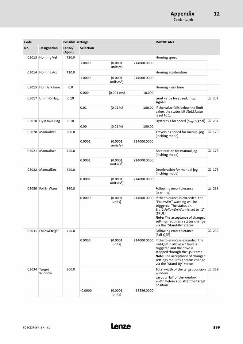
AppendixCode table
12
� 399EDBCSXP064 EN 8.0
IMPORTANTPossible settingsCode
SelectionLenze/{Appl.}
DesignationNo.
C3013 Homing Vel 720.0 Homing speed
1.0000 {0.0001units/s}
214000.0000
C3014 Homing Acc 720.0 Homing acceleration
1.0000 {0.0001units/s2}
214000.0000
C3015 HomJerkTime 0.0 Homing − jerk time
0.000 {0.001 ms} 10.000
C3017 Lim.n=0−Flag 0.10 Limit value for speed, (nminsignal)
� 231
0.01 {0.01 %} 100.00 If the value falls below the limitvalue, the status bit Stat2.Nminis set to 1.
C3018 Hyst.n=0−Flag 0.10 Hysteresis for speed (nmin signal) � 231
0.00 {0.01 %} 100.00
C3020 ManualVel 360.0 Traversing speed for manual jog(inching mode)
� 173
0.0001 {0.0001units/s}
214000.0000
C3021 ManualAcc 720.0 Acceleration for manual jog(inching mode)
� 173
0.0001 {0.0001units/s2}
214000.0000
C3022 ManualDec 720.0 Deceleration for manual jog(inching mode)
� 173
0.0001 {0.0001units/s2}
214000.0000
C3030 FollErrWarn 360.0 Following error tolerance(warning)
� 233
0.0000 {0.0001units}
214000.0000 If the tolerance is exceeded, the"FollowErr" warning will betriggered. The status bitStat2.FollowErrWarn is set to "1"(TRUE).Note: The acceptance of changedsettings requires a status changevia the "Stand−By" status!
C3031 FollowErrQSP 720.0 Following error tolerance(Fail−QSP)
� 233
0.0000 {0.0001units}
214000.0000 If the tolerance is exceeded, theFail−QSP "FollowErr" fault istriggered and the drive isstopped through the QSP ramp.Note: The acceptance of changedsettings requires a status changevia the "Stand−By" status!
C3034 TargetWindow
360.0 Total width of the target positionwindowLayout: Half of the windowwidth before and after the targetposition
� 229
−0.0000 {0.0001units}
65536.0000
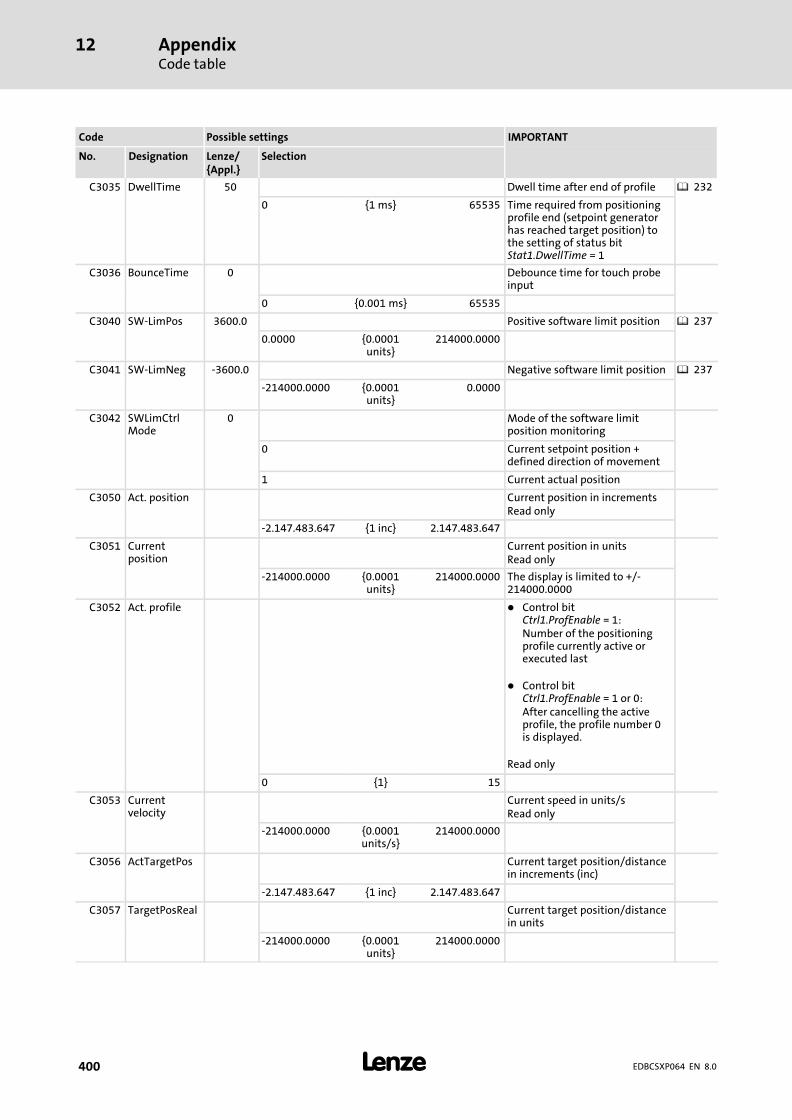
AppendixCode table
12
� 400 EDBCSXP064 EN 8.0
IMPORTANTPossible settingsCode
SelectionLenze/{Appl.}
DesignationNo.
C3035 DwellTime 50 Dwell time after end of profile � 232
0 {1 ms} 65535 Time required from positioningprofile end (setpoint generatorhas reached target position) tothe setting of status bitStat1.DwellTime = 1
C3036 BounceTime 0 Debounce time for touch probeinput
0 {0.001 ms} 65535
C3040 SW−LimPos 3600.0 Positive software limit position � 237
0.0000 {0.0001units}
214000.0000
C3041 SW−LimNeg −3600.0 Negative software limit position � 237
−214000.0000 {0.0001units}
0.0000
C3042 SWLimCtrlMode
0 Mode of the software limitposition monitoring
0 Current setpoint position +defined direction of movement
1 Current actual position
C3050 Act. position Current position in incrementsRead only
−2.147.483.647 {1 inc} 2.147.483.647
C3051 Currentposition
Current position in unitsRead only
−214000.0000 {0.0001units}
214000.0000 The display is limited to +/−214000.0000
C3052 Act. profile � Control bitCtrl1.ProfEnable = 1:Number of the positioningprofile currently active orexecuted last
� Control bitCtrl1.ProfEnable = 1 or 0:After cancelling the activeprofile, the profile number 0is displayed.
Read only
0 {1} 15
C3053 Currentvelocity
Current speed in units/sRead only
−214000.0000 {0.0001units/s}
214000.0000
C3056 ActTargetPos Current target position/distancein increments (inc)
−2.147.483.647 {1 inc} 2.147.483.647
C3057 TargetPosReal Current target position/distancein units
−214000.0000 {0.0001units}
214000.0000
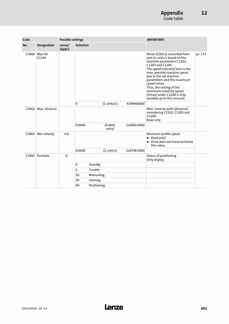
AppendixCode table
12
� 401EDBCSXP064 EN 8.0
IMPORTANTPossible settingsCode
SelectionLenze/{Appl.}
DesignationNo.
C3060 Max forC1240
Nmax (C0011) converted fromrpm to units/s based on themachine parameters C1202,C1203 and C1204.The speed indicated here is themax. possible machine speeddue to the set machineparameters and the maximumspeed nmax.Thus, the setting of themaximum machine speed(Vmax) under C1240 is onlysensible up to this amount.
� 173
0 {1 units/s} 4294960000
C3062 Max. distance Max. traverse path (distance)considering C1202, C1203 andC1204.Read only
0.0000 {0.0001units}
214000.0000
C3063 Min velocity 0.0 Minimum profile speed� Read only!� Drive does not traverse below
this value.
0.0000 {1 unit/s} 214748.0000
C3065 PosState 0 Status of positioningOnly display
0 StandBy
1 Trouble
20 ManualJog
30 Homing
40 Positioning
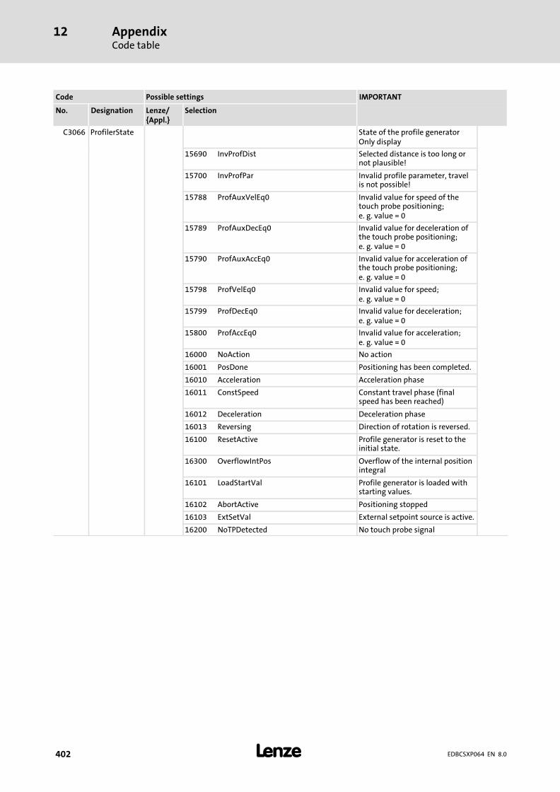
AppendixCode table
12
� 402 EDBCSXP064 EN 8.0
IMPORTANTPossible settingsCode
SelectionLenze/{Appl.}
DesignationNo.
C3066 ProfilerState State of the profile generatorOnly display
15690 InvProfDist Selected distance is too long ornot plausible!
15700 InvProfPar Invalid profile parameter, travelis not possible!
15788 ProfAuxVelEq0 Invalid value for speed of thetouch probe positioning;e. g. value = 0
15789 ProfAuxDecEq0 Invalid value for deceleration ofthe touch probe positioning;e. g. value = 0
15790 ProfAuxAccEq0 Invalid value for acceleration ofthe touch probe positioning;e. g. value = 0
15798 ProfVelEq0 Invalid value for speed;e. g. value = 0
15799 ProfDecEq0 Invalid value for deceleration;e. g. value = 0
15800 ProfAccEq0 Invalid value for acceleration;e. g. value = 0
16000 NoAction No action
16001 PosDone Positioning has been completed.
16010 Acceleration Acceleration phase
16011 ConstSpeed Constant travel phase (finalspeed has been reached)
16012 Deceleration Deceleration phase
16013 Reversing Direction of rotation is reversed.
16100 ResetActive Profile generator is reset to theinitial state.
16300 OverflowIntPos Overflow of the internal positionintegral
16101 LoadStartVal Profile generator is loaded withstarting values.
16102 AbortActive Positioning stopped
16103 ExtSetVal External setpoint source is active.
16200 NoTPDetected No touch probe signal

AppendixCode table
12
� 403EDBCSXP064 EN 8.0
IMPORTANTPossible settingsCode
SelectionLenze/{Appl.}
DesignationNo.
C3095 Mode selection for positioningprofiles 1 ... 15
� 191
1 Prof.Mode 1 modulo pos. Positioning profile 1
... ... ... ... ...
15 Prof.Mode 1 modulo pos. Positioning profile 15
0 absolute pos. Absolute positioning
1 modulo pos. Relative positioning incontinuous measuring system
2 speed mode Constant traversing
3 relative pos. Relative positioning withabsolute reference
10 absTP−rel_E3+ Absolute touch probepositioning (positive edge atX6/DI3)
11 modTP−rel_E3+ Relative touch probe positioning(positive edge at X6/DI3)
13 relTP−rel_E3+ Relative touch probe positioningwith absolute reference (positiveedge at X6/DI3)
20 absTP−rel_E3− Absolute touch probepositioning (negative edge atX6/DI3)
21 modTP−rel_E3− Relative touch probe positioning(negative edge at X6/DI3)
23 relTP−rel_E3− Relative touch probe positioningwith absolute reference(negative edge at X6/DI3)
30 EShaftX8_IS Electrical shaft with setpoint viaX8 and instant start
31 EShaftX4_IS Electrical shaft with setpoint viaX4 and instant start
100 homing Homing
101 set home pos. Set home position
102 reset home pos. Reset home position
110 abs. direct Absolute positioning (direct)
111 mod direct Relative positioning incontinuous measuring system(direct)
112 speed direct Continuous constant travel(direct)
113 rel. direct Relative positioning withabsolute reference (direct)
251 mod cycle +/− Positioning sequence forcontroller optimisation� The distance travelled in
positive/negative direction isselected under C3100.
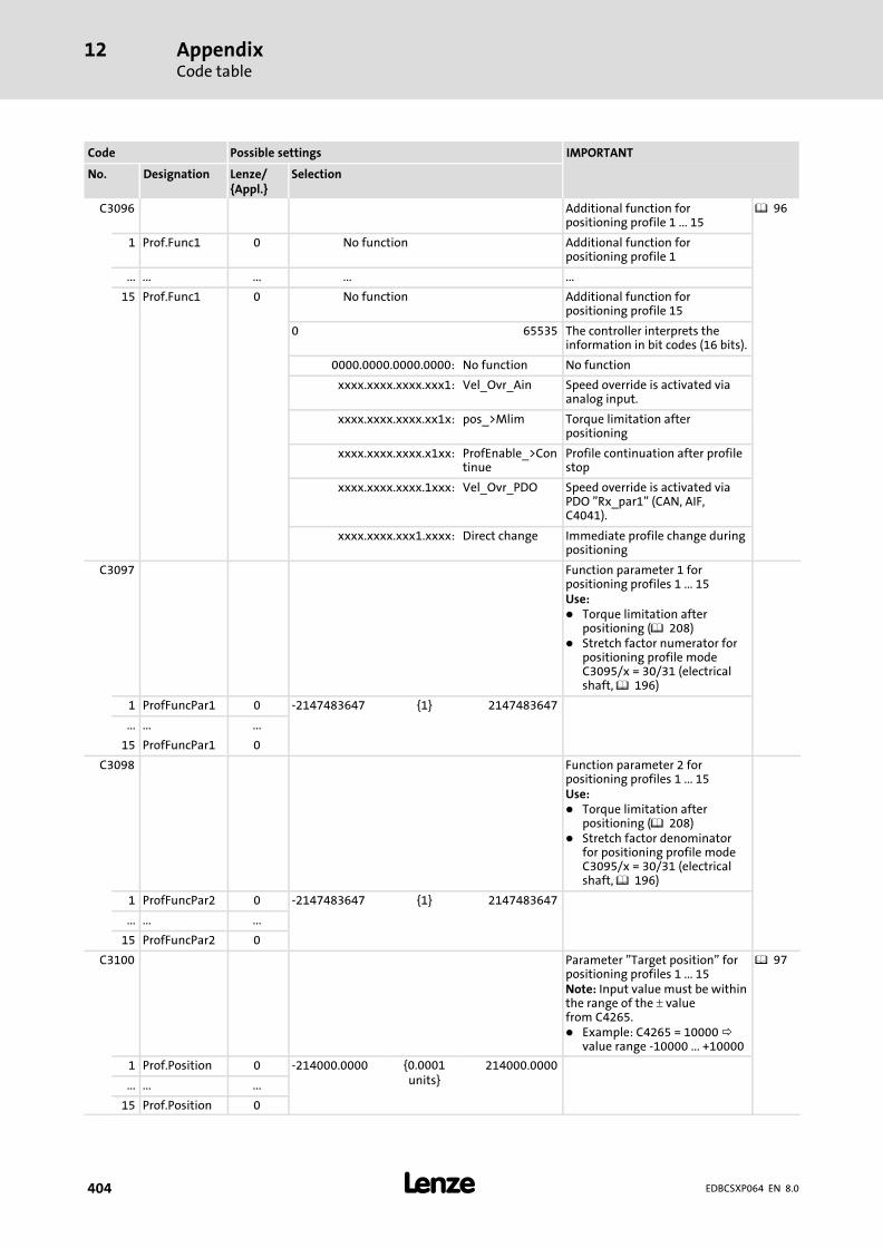
AppendixCode table
12
� 404 EDBCSXP064 EN 8.0
IMPORTANTPossible settingsCode
SelectionLenze/{Appl.}
DesignationNo.
C3096 Additional function forpositioning profile 1 ... 15
� 96
1 Prof.Func1 0 No function Additional function forpositioning profile 1
... ... ... ... ...
15 Prof.Func1 0 No function Additional function forpositioning profile 15
0 65535 The controller interprets theinformation in bit codes (16 bits).
0000.0000.0000.0000: No function No function
xxxx.xxxx.xxxx.xxx1: Vel_Ovr_Ain Speed override is activated viaanalog input.
xxxx.xxxx.xxxx.xx1x: pos_>Mlim Torque limitation afterpositioning
xxxx.xxxx.xxxx.x1xx: ProfEnable_>Continue
Profile continuation after profilestop
xxxx.xxxx.xxxx.1xxx: Vel_Ovr_PDO Speed override is activated viaPDO "Rx_par1" (CAN, AIF,C4041).
xxxx.xxxx.xxx1.xxxx: Direct change Immediate profile change duringpositioning
C3097 Function parameter 1 forpositioning profiles 1 ... 15Use:� Torque limitation after
positioning (� 208)� Stretch factor numerator for
positioning profile modeC3095/x = 30/31 (electricalshaft, � 196)
1 ProfFuncPar1 0 −2147483647 {1} 2147483647
... ... ...
15 ProfFuncPar1 0
C3098 Function parameter 2 forpositioning profiles 1 ... 15Use:� Torque limitation after
positioning (� 208)� Stretch factor denominator
for positioning profile modeC3095/x = 30/31 (electricalshaft, � 196)
1 ProfFuncPar2 0 −2147483647 {1} 2147483647
... ... ...
15 ProfFuncPar2 0
C3100 Parameter "Target position" forpositioning profiles 1 ... 15Note: Input value must be withinthe range of the � valuefrom C4265.� Example: C4265 = 10000
value range −10000 ... +10000
� 97
1 Prof.Position 0 −214000.0000 {0.0001units}
214000.0000
... ... ...
15 Prof.Position 0
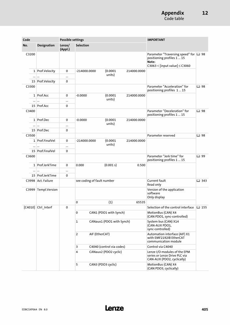
AppendixCode table
12
� 405EDBCSXP064 EN 8.0
IMPORTANTPossible settingsCode
SelectionLenze/{Appl.}
DesignationNo.
C3200 Parameter "Traversing speed" forpositioning profiles 1 ... 15Note:C3063 < [input value] ≤ C3060
� 98
1 Prof.Velocity 0 −214000.0000 {0.0001units}
214000.0000
... ... ...
15 Prof.Velocity 0
C3300 Parameter "Acceleration" forpositioning profiles 1 ... 15
� 98
1 Prof.Acc 0 −0.0000 {0.0001units}
214000.0000
... ... ...
15 Prof.Acc 0
C3400 Parameter "Deceleration" forpositioning profiles 1 ... 15
� 98
1 Prof.Dec 0 −0.0000 {0.0001units}
214000.0000
... ... ...
15 Prof.Dec 0
C3500 Parameter reserved � 98
1 Prof.FinalVel 0 −214000.0000 {0.0001units}
214000.0000
... ... ...
15 Prof.FinalVel 0
C3600 Parameter "Jerk time" forpositioning profiles 1 ... 15
� 99
1 Prof.JerkTime 0 0.000 {0.001 s} 0.500
... ... ...
15 Prof.JerkTime 0
C3998 Act. Failure see coding of fault number Current faultRead only
� 343
C3999 Templ.Version Version of the applicationsoftwareOnly display
0 {1} 65535
[C4010] Ctrl_Interf 0 Selection of the control interface � 155
0 CAN1 (PDO1 with Synch) MotionBus (CAN) X4(CAN PDO1, sync−controlled)
1 CANaux1 (PDO1 with Synch) System bus (CAN) X14(CAN−AUX PDO1,sync−controlled)
2 AIF (EtherCAT) Automation interface (AIF) X1with EMF2192IB EtherCATcommunication module
3 C4040 (control via codes) Control via C4040
4 CANaux2 (PDO2 cyclic) Lenze I/O modules of the EPMseries or Lenze Drive PLC viaCAN−AUX (PDO2, cyclically)
5 CAN3 (PDO3 cyclic) MotionBus (CAN) X4(CAN PDO3, cyclically)
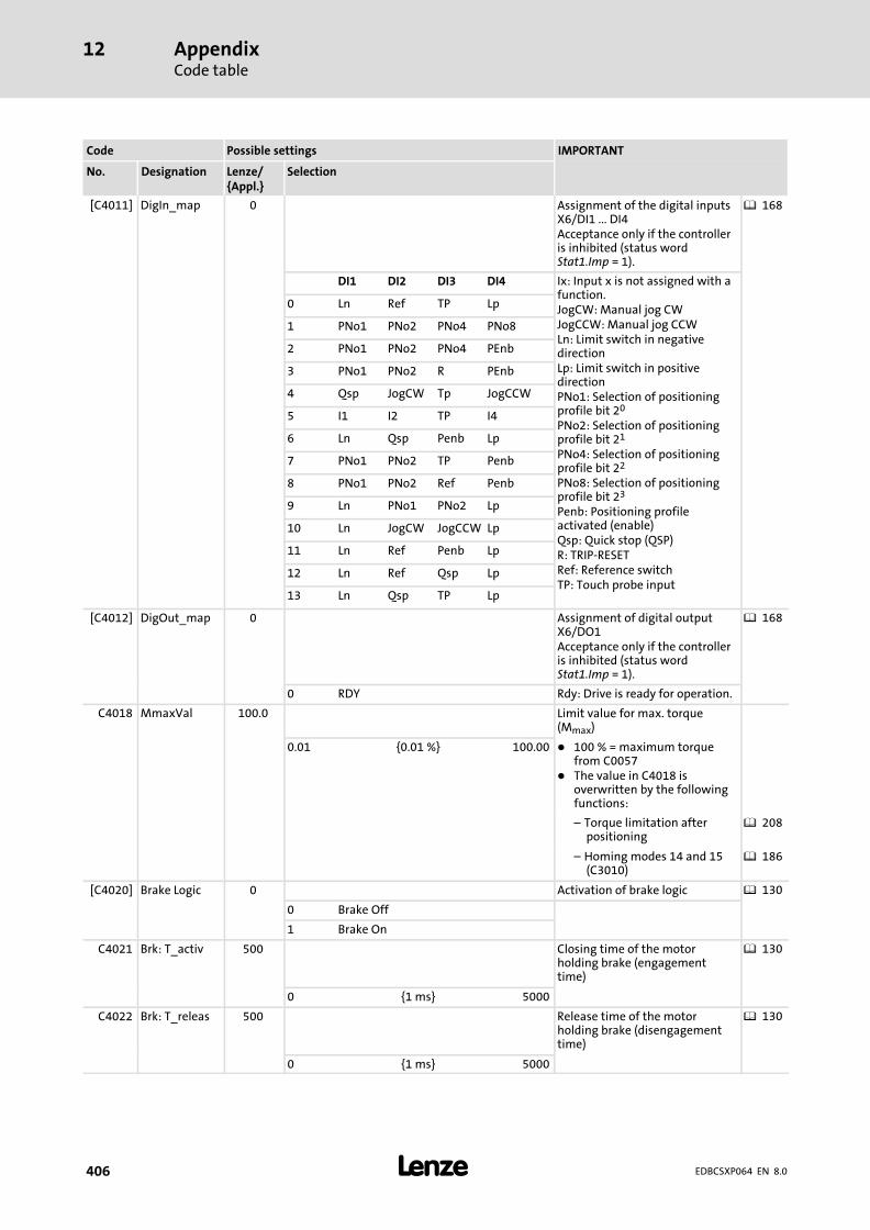
AppendixCode table
12
� 406 EDBCSXP064 EN 8.0
IMPORTANTPossible settingsCode
SelectionLenze/{Appl.}
DesignationNo.
[C4011] DigIn_map 0 Assignment of the digital inputsX6/DI1 ... DI4Acceptance only if the controlleris inhibited (status wordStat1.Imp = 1).
� 168
DI1 DI2 DI3 DI4 Ix: Input x is not assigned with afunction.JogCW: Manual jog CWJogCCW: Manual jog CCWLn: Limit switch in negativedirectionLp: Limit switch in positivedirectionPNo1: Selection of positioningprofile bit 20
PNo2: Selection of positioningprofile bit 21
PNo4: Selection of positioningprofile bit 22
PNo8: Selection of positioningprofile bit 23
Penb: Positioning profileactivated (enable)Qsp: Quick stop (QSP)R: TRIP−RESETRef: Reference switchTP: Touch probe input
0 Ln Ref TP Lp
1 PNo1 PNo2 PNo4 PNo8
2 PNo1 PNo2 PNo4 PEnb
3 PNo1 PNo2 R PEnb
4 Qsp JogCW Tp JogCCW
5 I1 I2 TP I4
6 Ln Qsp Penb Lp
7 PNo1 PNo2 TP Penb
8 PNo1 PNo2 Ref Penb
9 Ln PNo1 PNo2 Lp
10 Ln JogCW JogCCW Lp
11 Ln Ref Penb Lp
12 Ln Ref Qsp Lp
13 Ln Qsp TP Lp
[C4012] DigOut_map 0 Assignment of digital outputX6/DO1Acceptance only if the controlleris inhibited (status wordStat1.Imp = 1).
� 168
0 RDY Rdy: Drive is ready for operation.
C4018 MmaxVal 100.0 Limit value for max. torque(Mmax)
0.01 {0.01 %} 100.00 � 100 % = maximum torquefrom C0057
� The value in C4018 isoverwritten by the followingfunctions:
– Torque limitation afterpositioning
� 208
– Homing modes 14 and 15(C3010)
� 186
[C4020] Brake Logic 0 Activation of brake logic � 130
0 Brake Off
1 Brake On
C4021 Brk: T_activ 500 Closing time of the motorholding brake (engagementtime)
� 130
0 {1 ms} 5000
C4022 Brk: T_releas 500 Release time of the motorholding brake (disengagementtime)
� 130
0 {1 ms} 5000
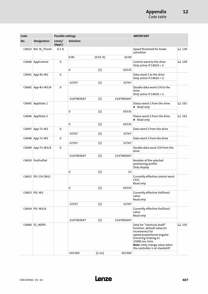
AppendixCode table
12
� 407EDBCSXP064 EN 8.0
IMPORTANTPossible settingsCode
SelectionLenze/{Appl.}
DesignationNo.
C4023 Brk: N_Thresh 0.1 % Speed threshold for brakeactivation
� 130
0.00 {0.01 %} 10.00
C4040 AppControl 0 Control word to the driveOnly active if C4010 = 3.
� 158
0 {1} 65535
C4041 App−Rx−W2 0 Data word 2 to the driveOnly active if C4010 = 3.
−32767 {1} 32767
C4042 App−Rx−W3/4 0 Double data word 3/4 to thedriveOnly active if C4010 = 3.
−2147483647 {1} 2147483647
C4045 AppState 1 Status word 1 from the drive� Read only
� 161
0 {1} 65535
C4046 AppState 2 Status word 2 from the drive� Read only
� 161
0 {1} 65535
C4047 App−Tx−W2 0 Data word 2 from the drive
−32767 {1} 32767
C4048 App−Tx−W3 0 Data word 3 from the drive
−32767 {1} 32767
C4049 App−Tx−W3/4 0 Double data word 3/4 from thedrive
−2147483647 {1} 2147483647
C4050 PosProfSel Number of the selectedpositioning profileOnly display
0 {1} 15
C4052 PO: Ctrl (W1) Currently effective control wordCtrl1Read only
0 {1} 65535
C4053 PO: W2 Currently effective VelDirectvalueRead only
−32767 {1} 32767
C4054 PO: W3/4 Currently effective PosDirectvalueRead only
−2147483647 {1} 2147483647
C4060 ES_NOffs Only for "electrical shaft"function: default value (inincrements) forspeed−proportional angulartrimming relating to15000 rev./min.Note: Only change value whenthe controller is at standstill!
� 235
−655360 {1 inc} 655360

AppendixCode table
12
� 408 EDBCSXP064 EN 8.0
IMPORTANTPossible settingsCode
SelectionLenze/{Appl.}
DesignationNo.
C4061 ES_ActNOffset
Only for "electrical shaft"function: Currently active valueof the angular trimming relatingto 15000 rev./min at currentspeed.Read only
� 235
[C4062] ES_MCycle 0 Only for "electrical shaft"function: Setpoint cycle ofmaster activates transmission ofmaster angle in the selected timeinterval.
0 Off
1 2 ms
Value is written in C0369.
2 4 ms
3 6 ms
4 8 ms
5 10 ms
C4166 TripAppReset 0 Application fault message reset. � 338
0 Fault message active
1 Reset fault message
C4167 AppHistReset 0 Deleting application faultmessage history buffer.
� 338
0 No reaction
1 Delete history buffer
C4168 History buffer (list of applicationfaults occurred)Read only
� 338� 343
1 AppFailNo Current fault
2 AppFailNo Last
3 AppFailNo Last but one
4 AppFailNo Last but two
5 AppFailNo Last but three
All fault messages(TRIP, KSB−TRIP, FAIL−QSP, warning, message)
C4169 Time when the application faultsentered into the history buffer(C4168) occurred.Read only
� 338
1 FailTime Individual power−on times (C0179) Currently active fault
2 FailTime Last fault
3 FailTime Last but one fault
4 FailTime Last but two fault
0 {1 h} 65535
C4240 ActVal C3040 0.0 Internal value C3040(limitation possible via C3030)
−214000.0000 {0.0001units}
2140000.0000
C4241 ActVal C3041 0.0 Internal value C3041(limitation possible via C3031)
−214000.0000 {0.0001units}
2140000.0000

AppendixCode table
12
� 409EDBCSXP064 EN 8.0
IMPORTANTPossible settingsCode
SelectionLenze/{Appl.}
DesignationNo.
C4263 CanSetValCyc Cycle time of the setpointselection at control programsynchronisationOnly display
2 {2 ms} 12
C4264 CanSync_Dev 0 Deviation of the control programsynchronisationThis also applies tosynchronisation via the digitalinput X6/DI1.Read only
� 279
−32767 {1} 32767
C4265 MaxTargetInp Max. target position input (inunits)Read only
� 103
−214000.0000 {0.0001units}
214000.0000
C4266 PosRes 0 Lenze−internal parameter setidentifierRead only
� 103
0 {1inc/unit}
2140000000 Position resolution in incrementsper unit1 revolution of position
encoder � 65536 increments
C4270 CAN Ctrl1 CAN application control word 1Read only
Text[1]=DIS: Ctrl1 appl. control word from CAN1−Out
Text[2]=DIS: Ctrl1 appl. control word from CANaux1−In
Text[3]=DIS: Ctrl1 appl. control word from AIF
Text[4]=DIS: Ctrl1 appl. control word from C4040
Text[5]=DIS: Ctrl1 appl. control word from CANaux2−In
Text[6]=DIS: Ctrl1 appl. control word from CAN3−In
C4271 CAN Stat1 CAN application status word 1Read only
Text[1]=DIS: Stat1 appl. status word 1 to CAN1−Out
Text[2]=DIS: Stat1 appl. status word 1 to CANaux1−Out
Text[3]=DIS: Stat1 app. status word 1 to AIF1−Out
Text[4]=DIS: Stat1 appl. status word 1 to C4040
Text[5]=DIS: Stat1 appl. status word 1 to CANaux2−Out
Text[6]=DIS: Stat1 appl. status word 1 to CAN3−Out
C4272 CAN Stat2 CAN application status word 2Read only
Text[1]=DIS: Stat2 appl. status word 2 to CAN1−Out
Text[2]=DIS: Stat2 appl. status word 2 to CANaux1−Out
Text[3]=DIS: Stat2 appl. status word 2 to AIF1
Text[4]=DIS: Stat2 appl. status word 2 to C4040
Text[5]=DIS: Stat2 appl. status word 2 to CANaux2−Out
Text[6]=DIS: Stat2 appl. status word 2 to CAN3−Out
C7900 L_GDC_Vers Lenze−internal versionidentification(e.g. V1.2 = 1020000)Read only
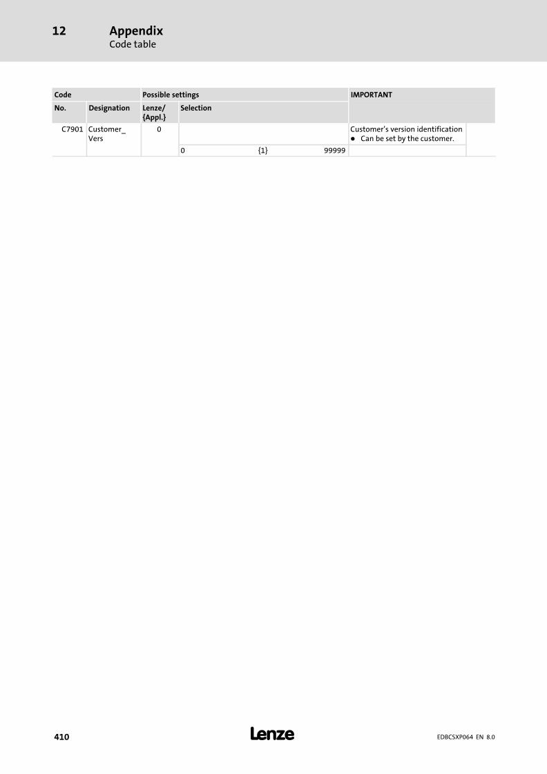
AppendixCode table
12
� 410 EDBCSXP064 EN 8.0
IMPORTANTPossible settingsCode
SelectionLenze/{Appl.}
DesignationNo.
C7901 Customer_Vers
0 Customer’s version identification� Can be set by the customer.
0 {1} 99999
AppendixGeneral information about the system bus (CAN)
12
� 411EDBCSXP064 EN 8.0
12.2 General information about the system bus (CAN)
All Lenze drive and automation systems are provided with an integrated system businterface for networking control components on the field level.
The system bus interface serves to exchange, for instance, process data and parametervalues between the nodes. Moreover, the interface allows for the connection of furtherdevices as e.g. decentralised terminals, operator and input devices and external controland host systems.
The system bus interface transfers CAN objects to the CANopen communication profile(CiA DS301, version 4.01) which has been created under the umbrella association of theder CiA (CAN in Automation) to conform with the CAL (CAN Application Layer).
� Tip!
For further information visit the homepage of the CAN user organisation CiA(CAN in Automation): www.can−cia.org.
� Note!
System bus (CAN)
The ECSxA... axis module can communicate with a higher−level host system(PLC) or further controllers via both CAN interfaces (X4 or X14).
MotionBus (CAN)
The "MotionBus (CAN)" term expresses the functionality of the CAN interfaceX4 in case of ECSxS/P/M... axis modules, where communication takes placeusing a higher−level host system (PLC) or further controllers exclusively via theX4 interface. Interface X14 (CAN−AUX) is exclusively used for parameter settingand diagnostics.
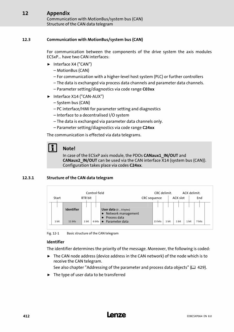
AppendixCommunication with MotionBus/system bus (CAN)Structure of the CAN data telegram
12
� 412 EDBCSXP064 EN 8.0
12.3 Communication with MotionBus/system bus (CAN)
For communication between the components of the drive system the axis modulesECSxP... have two CAN interfaces:
ƒ Interface X4 ("CAN")
– MotionBus (CAN)
– For communication with a higher−level host system (PLC) or further controllers
– The data is exchanged via process data channels and parameter data channels.
– Parameter setting/diagnostics via code range C03xx
ƒ Interface X14 ("CAN−AUX")
– System bus (CAN)
– PC interface/HMI for parameter setting and diagnostics
– Interface to a decentralised I/O system
– The data is exchanged via parameter data channels only.
– Parameter setting/diagnostics via code range C24xx
The communication is effected via data telegrams.
� Note!
In case of the ECSxP axis module, the PDOs CANaux1_IN/OUT andCANaux2_IN/OUT can be used via the CAN interface X14 (system bus (CAN)).Configuration takes place via codes C24xx.
12.3.1 Structure of the CAN data telegram
Control field CRC delimit. ACK delimit.
Start RTR bit CRC sequence ACK slot End
Identifier User data (0 ... 8 bytes)
� Network management� Process data� Parameter data1 bit 11 bits 1 bit 6 bits 15 bits 1 bit 1 bit 1 bit 7 bits
Fig. 12−1 Basic structure of the CAN telegram
Identifier
The identifier determines the priority of the message. Moreover, the following is coded:
ƒ The CAN node address (device address in the CAN network) of the node which is toreceive the CAN telegram.
See also chapter "Addressing of the parameter and process data objects" ( 429).
ƒ The type of user data to be transferred

AppendixCommunication with MotionBus/system bus (CAN)
Structure of the CAN data telegram
12
� 413EDBCSXP064 EN 8.0
User data
The user data area of the CAN telegram either contains network management data,process data or parameter data:
User data Description
Network management data(NMT data)
The information serves to establish communication via the CAN network
Process data(PDO, Process Data Objects)
� Process data are transmitted via the process data channel.� The process data serve to control the controller.� Process data can be accessed directly by the higher−level host system.
The data are, for instance, stored directly in the I/O area of the PLC. It isnecessary that the data can be exchanged between the host systemand the controller within the shortest time possible. In this connection,small amounts of data can be transferred cyclically.
� Process data are transmitted between the higher−level host system andthe controllers to ensure a permanent exchange of current input andoutput data.
� Process data are not stored in the controller.� Process data are, for instance, setpoints and actual values.
Parameter data(SDO, Service Data Objects)
� Parameter data are transferred via the parameter data channel andacknowledged by the receiver, i.e. the receiver gets a feedback whetherthe transmission was successful.
� Parameter data of Lenze devices are called codes.� The parameter data channel enables access to all Lenze codes and all
CANopen indexes.� Parameters are set, for instance, for the initial commissioning of a
plant or when material of a production machine is exchanged.� Usually the transfer of parameters is not time−critical.� Parameter changes are stored in the controller.� Parameter data are, for instance, operating parameters, diagnostic
information and motor data.
� Tip!
The other signals refer to the transfer features of the CAN telegram that arenot described in these instructions.
For further information visit the homepage of the CAN user organisation CiA(CAN in Automation): www.can−cia.org.
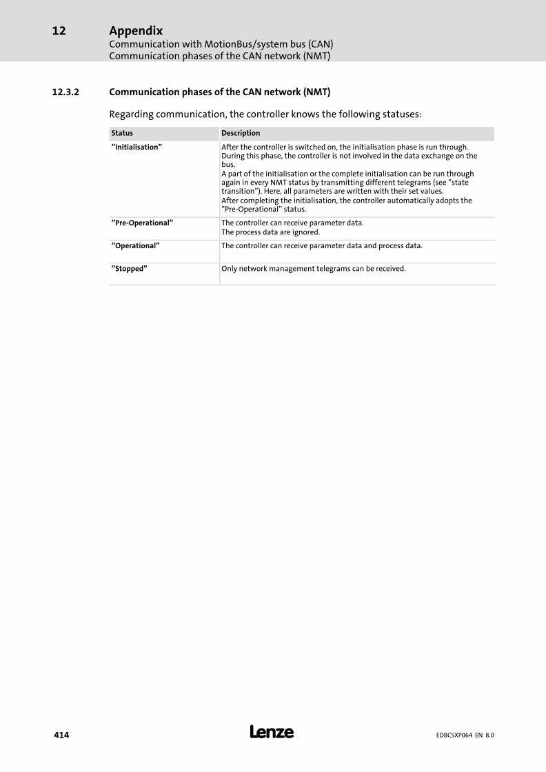
AppendixCommunication with MotionBus/system bus (CAN)Communication phases of the CAN network (NMT)
12
� 414 EDBCSXP064 EN 8.0
12.3.2 Communication phases of the CAN network (NMT)
Regarding communication, the controller knows the following statuses:
Status Description
"Initialisation" After the controller is switched on, the initialisation phase is run through.During this phase, the controller is not involved in the data exchange on thebus.A part of the initialisation or the complete initialisation can be run throughagain in every NMT status by transmitting different telegrams (see "statetransition"). Here, all parameters are written with their set values.After completing the initialisation, the controller automatically adopts the"Pre−Operational" status.
"Pre−Operational" The controller can receive parameter data.The process data are ignored.
"Operational" The controller can receive parameter data and process data.
"Stopped" Only network management telegrams can be received.

AppendixCommunication with MotionBus/system bus (CAN)Communication phases of the CAN network (NMT)
12
� 415EDBCSXP064 EN 8.0
State transitions
(3)
(11)
(10)
(9)(8)
(6)
(7)
(5)(4)
(2)
(1)
(13)
(12)
(14)
Initialisation
Pre-Operational
Stopped
Operational
E82ZAFU004
Fig. 12−2 State transitions in the CAN network (NMT)
Statetransition
Command(hex)
Network status afterchange
Effect on process or parameter data after state change
(1) − Initialisation
When the mains is switched on, the initialisation isstarted automatically.During the initialisation the controller is not involved inthe data exchange.After the initialisation is completed, the node changesautomatically to the "Pre−Operational" status.
(2) − Pre−operationalIn this phase the master decides how the controllers takepart in the communication.
From here, the states are changed over by the master for the entire network. A target address included in thecommand specifies the receiver/s.
(3), (6) 01xx Operational
Network management telegrams, sync, emergency,process data (PDO) and parameter data (SDO) are active(corresponds to "Start Remote Node")Optional:In case of change, event−controlled and time−controlledprocess data (PDO) are sent once.
(4), (7) 80 xx Pre−operationalNetwork management telegrams, sync, emergency, andparameter data (SDO) are active (corresponds to "EnterPre−Operational State")
(5), (8) 02 xx Stopped Only network management telegrams can be received.
(9)
81 xx
Initialisation
Initialisation of all parameters in the CAN fieldbusmodule with the values stored (corresponds to "ResetNode")
(10)
(11)
(12)
82 xxInitialisation of communication−relevant parameters(CiA DS 301) in the CAN fieldbus module with the valuesstored (corresponds to "Reset Communication")
(13)
(14)
yy = 00 In case of this assignment, the telegram addresses all devices connected. Thestate of all devices can be changed at the same time.
yy = node ID If a node address is given, only the state of the device with the correspondingaddress will be changed.
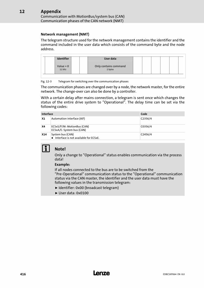
AppendixCommunication with MotionBus/system bus (CAN)Communication phases of the CAN network (NMT)
12
� 416 EDBCSXP064 EN 8.0
Network management (NMT)
The telegram structure used for the network management contains the identifier and thecommand included in the user data which consists of the command byte and the nodeaddress.
Identifier User data
Value = 011 bits
Only contains command2�bytes
Fig. 12−3 Telegram for switching over the communication phases
The communication phases are changed over by a node, the network master, for the entirenetwork. The change−over can also be done by a controller.
With a certain delay after mains connection, a telegram is sent once which changes thestatus of the entire drive system to "Operational". The delay time can be set via thefollowing codes:
Interface Code
X1 Automation interface (AIF) C2356/4
X4 ECSxS/P/M: MotionBus (CAN)ECSxA/E: System bus (CAN)
C0356/4
X14 System bus (CAN)� Interface is not available for ECSxE.
C2456/4
� Note!
Only a change to "Operational" status enables communication via the processdata!
Example:
If all nodes connected to the bus are to be switched from the"Pre−Operational" communication status to the "Operational" communicationstatus via the CAN master, the identifier and the user data must have thefollowing values in the transmission telegram:
ƒ Identifier: 0x00 (broadcast telegram)
ƒ User data: 0x0100

AppendixCommunication with MotionBus/system bus (CAN)
Process data transfer
12
� 417EDBCSXP064 EN 8.0
12.3.3 Process data transfer
Agreements
ƒ Process data telegrams between host (master) and controller (slave) aredistinguished as follows with regard to their direction:
– Process data telegrams to the controller
– Process data telegrams from the controller
ƒ In CANopen, the process data objects are named from the node’s view:
– RPDOx: A process data object received by a node
– TPDOx: A process data object transmitted by a node
12.3.3.1 Available process data objects
The following process data objects (PDOs) are available for the ECS modules via theinterfaces X1, X4 and X14:
Interface PDOsRPDO: to ECS moduleTPDO: from ECS module
Availability in ECS modules
ECSxE ECSxS ECSxP ECSxM ECSxA
X1Automation interface (AIF)
RPDO
AIF1_IN ˘ � V3.0 or
higher
V3.0 or
higher
�
AIF2_IN ˘ � ˘ ˘ �
AIF3_IN ˘ � ˘ ˘ �
TPDO
AIF1_OUT ˘ � V3.0 or
higher
V3.0 or
higher
�
AIF2_OUT ˘ � ˘ ˘ �
AIF3_OUT ˘ � ˘ ˘ �
X4ECSxS/P/M: MotionBus (CAN)ECSxA/E: System bus (CAN)
RPDO
CAN1_IN � � � � �
CAN2_IN ˘ � � ˘ �
CAN3_IN � � � ˘ �
TPDO
CAN1_OUT � � � � �
CAN2_OUT � 1) � � ˘ �
CAN3_OUT � � � ˘ �
X14System bus (CAN)Interface is not available for ECSxE.
RPDO
CANaux1_IN ˘ ˘ � ˘ �
CANaux2_IN ˘ ˘ � ˘ �
CANaux3_IN ˘ ˘ ˘ ˘ �
TPDO
CANaux1_OUT ˘ ˘ � ˘ �
CANaux2_OUT ˘ ˘ � ˘ �
CANaux3_OUT ˘ ˘ ˘ ˘ �
1) ECSxE from V5.0: CAN2_OUT (Diagnostic PDO)
� Note!
Power supply module ECSxE
In case of the ECSxE power supply module, the PDOs CAN1_IN/OUT andCAN3_IN/OUT cannot be used simultaneously. The PDOs to be used areselected via C0360.

AppendixCommunication with MotionBus/system bus (CAN)Process data transfer
12
� 418 EDBCSXP064 EN 8.0
12.3.3.2 Structure of the process data
The process data telegrams have a maximum user data length of eight bytes each.
Process data input telegram (RPDO)
ƒ The process data input telegram transmits control information to the controller.
ƒ The control word is transmitted in byte 1 and 2 of the user data.
Identifier User data (8 bytes)
Control word
00hex 00hex 00hex 00hex 00hex 00hex11 bits LOWbyte
HIGHbyte
Fig. 12−4 Structure of process data input telegram (RPDO)
Process data output telegram (TPDO)
ƒ The process data output telegram reports status information from the controller.Status information can be as follows:
– Current status of the controller
– Status of the digital inputs
– States about internal analog values
– Fault/error messages
This information enables the higher−level host system (PLC) to respond accordingly.
ƒ The status word 1 is transmitted in byte 1 and 2 of the user data.
ƒ In byte 3 and 4 of the user data, the extended status word 2 can be optionallytransferred.
Identifier User data (8 bytes)
Status word 1 Status word 2(optional)
00hex 00hex 00hex 00hex11 bits LOWbyte
HIGHbyte
LOWbyte
HIGHbyte
Fig. 12−5 Structure of process data output telegram (TPDO)
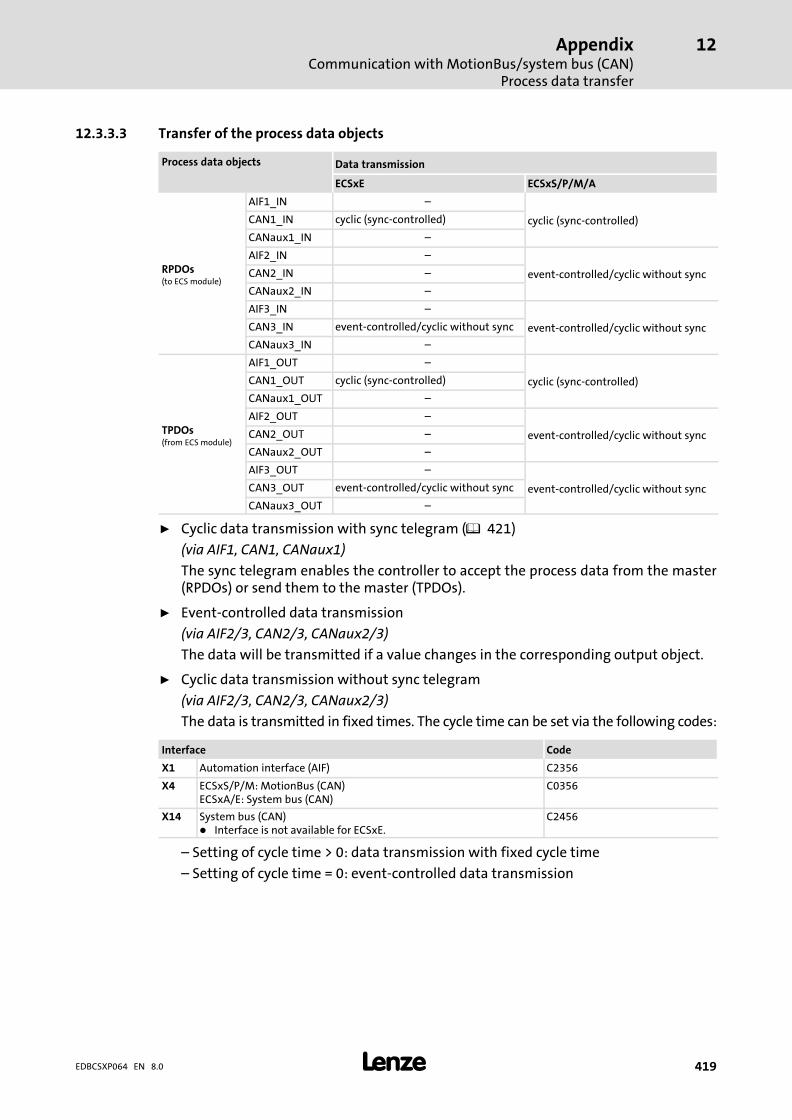
AppendixCommunication with MotionBus/system bus (CAN)
Process data transfer
12
� 419EDBCSXP064 EN 8.0
12.3.3.3 Transfer of the process data objects
Process data objects Data transmission
ECSxE ECSxS/P/M/A
RPDOs(to ECS module)
AIF1_IN ˘
cyclic (sync−controlled)CAN1_IN cyclic (sync−controlled)
CANaux1_IN ˘
AIF2_IN ˘
event−controlled/cyclic without syncCAN2_IN ˘
CANaux2_IN ˘
AIF3_IN ˘
event−controlled/cyclic without syncCAN3_IN event−controlled/cyclic without sync
CANaux3_IN ˘
TPDOs(from ECS module)
AIF1_OUT ˘
cyclic (sync−controlled)CAN1_OUT cyclic (sync−controlled)
CANaux1_OUT ˘
AIF2_OUT ˘
event−controlled/cyclic without syncCAN2_OUT ˘
CANaux2_OUT ˘
AIF3_OUT ˘
event−controlled/cyclic without syncCAN3_OUT event−controlled/cyclic without sync
CANaux3_OUT ˘
ƒ Cyclic data transmission with sync telegram (� 421)
(via AIF1, CAN1, CANaux1)
The sync telegram enables the controller to accept the process data from the master(RPDOs) or send them to the master (TPDOs).
ƒ Event−controlled data transmission
(via AIF2/3, CAN2/3, CANaux2/3)
The data will be transmitted if a value changes in the corresponding output object.
ƒ Cyclic data transmission without sync telegram
(via AIF2/3, CAN2/3, CANaux2/3)
The data is transmitted in fixed times. The cycle time can be set via the following codes:
Interface Code
X1 Automation interface (AIF) C2356
X4 ECSxS/P/M: MotionBus (CAN)ECSxA/E: System bus (CAN)
C0356
X14 System bus (CAN)� Interface is not available for ECSxE.
C2456
– Setting of cycle time > 0: data transmission with fixed cycle time
– Setting of cycle time = 0: event−controlled data transmission

AppendixCommunication with MotionBus/system bus (CAN)Process data transfer
12
� 420 EDBCSXP064 EN 8.0
12.3.3.4 Cyclic process data objects
X4
X14
X4
X14
X4
X14
X1 X1
X4
X14
X1 X1
PLC
Rx-PDO1
Tx-PDO1
ECSxS/P/M/A...ECSXA218
Fig. 12−6 Example: Cyclic process data transfer from/to master (PLC)
For the quick exchange of process data from or to the master respectively one process dataobject for input signals (Rx−PDO1) and one process data object for output signals(Tx−PDO18 ), each with 8 bytes of user data, is provided.
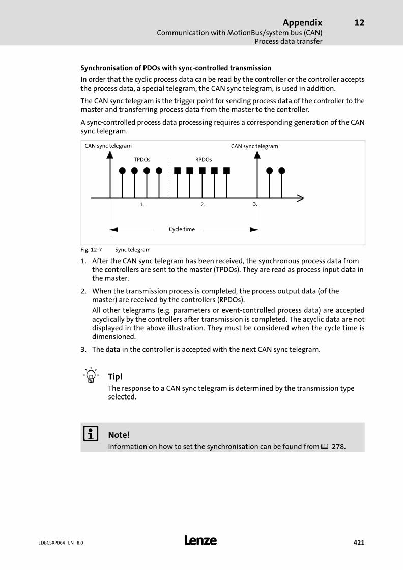
AppendixCommunication with MotionBus/system bus (CAN)
Process data transfer
12
� 421EDBCSXP064 EN 8.0
Synchronisation of PDOs with sync−controlled transmission
In order that the cyclic process data can be read by the controller or the controller acceptsthe process data, a special telegram, the CAN sync telegram, is used in addition.
The CAN sync telegram is the trigger point for sending process data of the controller to themaster and transferring process data from the master to the controller.
A sync−controlled process data processing requires a corresponding generation of the CANsync telegram.
1.
CAN sync telegram CAN sync telegram
Cycle time
TPDOs RPDOs
2. 3.
Fig. 12−7 Sync telegram
1. After the CAN sync telegram has been received, the synchronous process data fromthe controllers are sent to the master (TPDOs). They are read as process input data inthe master.
2. When the transmission process is completed, the process output data (of themaster) are received by the controllers (RPDOs).
All other telegrams (e.g. parameters or event−controlled process data) are acceptedacyclically by the controllers after transmission is completed. The acyclic data are notdisplayed in the above illustration. They must be considered when the cycle time isdimensioned.
3. The data in the controller is accepted with the next CAN sync telegram.
� Tip!
The response to a CAN sync telegram is determined by the transmission typeselected.
� Note!
Information on how to set the synchronisation can be found from � 278.

AppendixCommunication with MotionBus/system bus (CAN)Process data transfer
12
� 422 EDBCSXP064 EN 8.0
12.3.3.5 Event−controlled process data objects
The event−controlled process data objects are particularly suitable for the data exchangebetween controllers and for distributed terminal extensions. They can, however, also beused by a host system.
X14
X4
X14 X14X14
TPDO2RPDO2
X4 X4 X4
TPDO2RPDO2
TPDO2RPDO2
ECSxS/P/M/A...ECSXA219
Fig. 12−8 Example: event−controlled process data objects PDO2
The process data objects serve to transmit simple binary signals (e.g.� states of digital inputterminals) or complete values in 16 and 32 bits (e.g.� analog signals).
Event−controlled process data objects with adjustable cycle time (optional)
The output data is transmitted
ƒ event−controlled if a value changes within the user data (8�bytes) or
ƒ cyclically with the cycle time set:
Interface Code
x1 Automation interface (AIF) C2356
X4 ECSxS/P/M: MotionBus (CAN)ECSxA: system bus (CAN)
C0356
X14 System bus (CAN) C2456

AppendixCommunication with MotionBus/system bus (CAN)
Parameter data transfer
12
� 423EDBCSXP064 EN 8.0
12.3.4 Parameter data transfer
X4
X4
X14
X4
X14
X4
X14
Systembus (CAN)
MotionBus (CAN)
� ��
� � �
� �
� �����SHPRG
Para
Code
Menu
0050 00
50.00_Hz
MCTRL-NOUT
X4
X14
� � �
X1
�
SDO1
SDO2
�ECSXA220
Fig. 12−9 Parameter data channels for parameterising ECS
Parameters ...
ƒ are values which are stored under codes in the Lenze controllers.
ƒ are set e.g. during initial commissioning or while changing materials in a machine.
ƒ are transmitted with low priority.
Parameter data are transmitted as SDOs (Service Data Objects) via the system bus (CAN)and acknowledged by the receiver. The SDOs enable the writing and reading access to theobject directory.
The CAN bus interfaces X4 and X14 are provided with two separated parameter datachannels each which serve to simultaneously connect different devices for parametersetting and diagnostics.
The codes for parameter setting and diagnostics of the automation interface (AIF) X1 aswell as the CAN bus interfaces X4 and X14 are divided into separate ranges:
Interface Code range
X1 Automation interface (AIF) C23xx
X4 ECSxS/P/M: MotionBus (CAN)ECSxA/E: System bus (CAN)
C03xx
X14 System bus (CAN)� Interface is not available for ECSxE.
C24xx

AppendixCommunication with MotionBus/system bus (CAN)Parameter data transfer
12
� 424 EDBCSXP064 EN 8.0
12.3.4.1 User data
Structure of the parameter data telegram
User data (up to 8 bytes)
1. byte 2. byte 3. byte 4. byte 5. byte 6. byte 7. byte 8. byte
CommandIndex
Low byteIndex
High byteSubindex
Data 1 Data 2 Data 3 Data 4
Low word High word
Low byte High byte Low byte High byte
Display
� Note!
The user data is shown in motorola format.
Examples for parameter data transfer can be found from � 427.
Command
The command contains the services for writing and reading the parameters andinformation on the length of the user data:
Command
Bit 7MSB
Bit6 Bit5 Bit4 Bit3 Bit 2 Bit 1 Bit 0LSB
Command specifier (cs) toggle (t) Length e E
Write request 0 0 1 000 = 4 bytes01 = 3 bytes10 = 2 bytes11 = 1 byte
1 1
Write response 0 1 1 0 0 0
Read request 0 1 0 0 0 0
Read response 0 1 0 0 1 1
Error response 1 0 0 0 0 0 0 0
� Tip!
Further commands are defined in the CANopen specification DS301,�V4.02(e.g. segmented transfer).
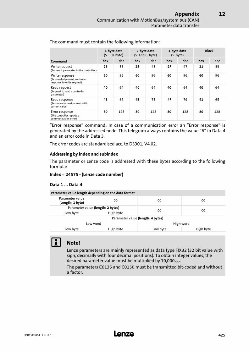
AppendixCommunication with MotionBus/system bus (CAN)
Parameter data transfer
12
� 425EDBCSXP064 EN 8.0
The command must contain the following information:
Command
4−byte data(5. ... 8. byte)
2−byte data(5. and 6. byte)
1−byte data(5. byte)
Block
hex dec hex dec hex dec hex dec
Write request(Transmit parameter to the controller )
23 35 2B 43 2F 47 21 33
Write response(Acknowledgement, controllerresponse to write request)
60 96 60 96 60 96 60 96
Read request(Request to read a controllerparameter)
40 64 40 64 40 64 40 64
Read response(Response to read request withcurrent value)
43 67 4B 75 4F 79 41 65
Error response(The controller reports acommunication error)
80 128 80 128 80 128 80 128
"Error response" command: In case of a communication error an "Error response" isgenerated by the addressed node. This telegram always contains the value "6" in Data 4and an error code in Data 3.
The error codes are standardised acc. to DS301, V4.02.
Addressing by index and subindex
The parameter or Lenze code is addressed with these bytes according to the followingformula:
Index = 24575 − (Lenze code number)
Data�1�...�Data�4
Parameter value length depending on the data format
Parameter value(Length: 1 byte)
00 00 00
Parameter value (length: 2 bytes)00 00
Low byte High byte
Parameter value (length: 4 bytes)
Low word High word
Low byte High byte Low byte High byte
� Note!
Lenze parameters are mainly represented as data type FIX32 (32�bit value withsign, decimally with four decimal positions). To obtain integer values, thedesired parameter value must be multiplied by 10,000dec.
The parameters C0135 and C0150 must be transmitted bit−coded and withouta factor.
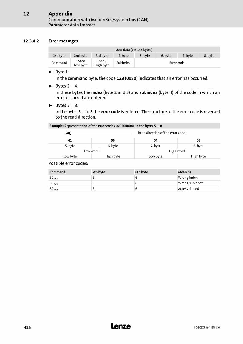
AppendixCommunication with MotionBus/system bus (CAN)Parameter data transfer
12
� 426 EDBCSXP064 EN 8.0
12.3.4.2 Error messages
User data (up to 8 bytes)
1st byte 2nd byte 3rd byte 4. byte 5. byte 6. byte 7. byte 8. byte
CommandIndex
Low byteIndex
High byteSubindex Error code
ƒ Byte 1:
In the command byte, the code 128 (0x80) indicates that an error has occurred.
ƒ Bytes 2 ... 4:
In these bytes the index (byte 2 and 3) and subindex (byte 4) of the code in which anerror occurred are entered.
ƒ Bytes 5 ... 8:
In the bytes 5 ... to 8 the error code is entered. The structure of the error code is reversedto the read direction.
Example: Representation of the error codes 0x06040041 in the bytes 5 ... 8
Read direction of the error code
41 00 04 06
5. byte 6. byte 7. byte 8. byte
Low word High word
Low byte High byte Low byte High byte
Possible error codes:
Command 7th byte 8th byte Meaning
80hex 6 6 Wrong index
80hex 5 6 Wrong subindex
80hex 3 6 Access denied

AppendixCommunication with MotionBus/system bus (CAN)
Parameter data transfer
12
� 427EDBCSXP064 EN 8.0
12.3.4.3 Examples of the parameter data telegram
Reading parameters
The heatsink temperature C0061 ( 43 °C) is to be read from the controller with nodeaddress 5 via the parameter data channel 1.
ƒ Identifier calculation
Identifier from SDO1 to controller Calculation
1536 + node address 1536 + 5 = 1541
ƒ Command "Read Request" (request to read a parameter from the controller)
Command Value [hex]
Read request 0x40
ƒ Index calculation
Index Calculation
24575 − code number 24575 − 61 = 24514 = 0x5FC2
ƒ Subindex: 0
ƒ Telegram to controller
Identifier
User data
Command IndexLOW byte
IndexHIGH byte
Subindex Data 1 Data 2 Data 3 Data 4
1541 0x40 0xC2 0x5F 0x00 0x00 0x00 0x00 0x00
ƒ Telegram from controller
Identifier
User data
Command IndexLOW byte
IndexHIGH byte
Subindex Data 1 Data 2 Data 3 Data 4
1413 0x43 0xC2 0x5F 0x00 0xB0 0x8F 0x06 0x00
– Command:"Read Response" (response to the read request) = 0x43
– Identifier:SDO1 from controller (1408) + node address (5) = 1413
– Index of the read request:0x5FC2
– Subindex:0
– Data 1 ... 4:0x00068FB0 = 430000 � 430000 : 10000 = 43 °C
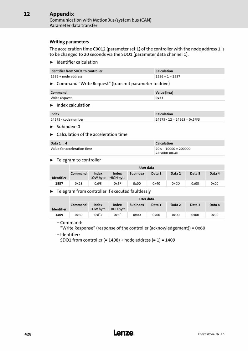
AppendixCommunication with MotionBus/system bus (CAN)Parameter data transfer
12
� 428 EDBCSXP064 EN 8.0
Writing parameters
The acceleration time C0012 (parameter set 1) of the controller with the node address 1 isto be changed to 20 seconds via the SDO1 (parameter data channel 1).
ƒ Identifier calculation
Identifier from SDO1 to controller Calculation
1536 + node address 1536 + 1 = 1537
ƒ Command "Write Request" (transmit parameter to drive)
Command Value [hex]
Write request 0x23
ƒ Index calculation
Index Calculation
24575 − code number 24575 − 12 = 24563 = 0x5FF3
ƒ Subindex: 0
ƒ Calculation of the acceleration time
Data 1 ... 4 Calculation
Value for acceleration time 20 s � 10000 = 200000= 0x00030D40
ƒ Telegram to controller
Identifier
User data
Command IndexLOW byte
IndexHIGH byte
Subindex Data 1 Data 2 Data 3 Data 4
1537 0x23 0xF3 0x5F 0x00 0x40 0x0D 0x03 0x00
ƒ Telegram from controller if executed faultlessly
Identifier
User data
Command IndexLOW byte
IndexHIGH byte
Subindex Data 1 Data 2 Data 3 Data 4
1409 0x60 0xF3 0x5F 0x00 0x00 0x00 0x00 0x00
– Command:"Write Response" (response of the controller (acknowledgement)) = 0x60
– Identifier:SDO1 from controller (= 1408) + node address (= 1) = 1409
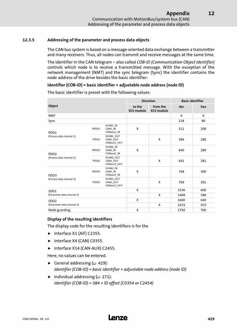
AppendixCommunication with MotionBus/system bus (CAN)
Addressing of the parameter and process data objects
12
� 429EDBCSXP064 EN 8.0
12.3.5 Addressing of the parameter and process data objects
The CAN bus system is based on a message−oriented data exchange between a transmitterand many receivers. Thus, all nodes can transmit and receive messages at the same time.
The identifier in the CAN telegram ˘ also called COB−ID (Communication Object Identifier)controls which node is to receive a transmitted message. With the exception of thenetwork management (NMT) and the sync telegram (Sync) the identifier contains thenode address of the drive besides the basic identifier:
Identifier (COB−ID) = basic identifier + adjustable node address (node ID)
The basic identifier is preset with the following values:
Object
Direction Basic identifier
to theECS module
from theECS module
dec hex
NMT 0 0
Sync 128 80
PDO1(Process data channel 1)
RPDO1XCAN1_INCAN1_INCANaux1_IN
X 512 200
TPDO1XCAN1_OUTCAN1_OUTCANaux1_OUT
X 384 180
PDO2(Process data channel 2)
RPDO2XCAN2_INCAN2_INCANaux2_IN
X 640 280
TPDO2XCAN2_OUTCAN2_OUTCANaux2_OUT
X 641 281
PDO3(Process data channel 3)
RPDO3XCAN3_INCAN3_INCANaux3_IN
X 768 300
TPDO3XCAN3_OUTCAN3_OUTCANaux3_OUT
X 769 301
SDO1(Parameter data channel 1)
X 1536 600
X 1408 580
SDO2(Parameter data channel 2)
X 1600 640
X 1472 5C0
Node guarding X 1792 700
Display of the resulting identifiers
The display code for the resulting identifiers is for the
ƒ Interface X1 (AIF) C2355.
ƒ Interface X4 (CAN) C0355.
ƒ Interface X14 (CAN−AUX) C2455.
Here, no values can be entered.
ƒ General addressing (� 429):
Identifier (COB−ID) = basic identifier + adjustable node address (node ID)
ƒ Individual addressing (� 271):
Identifier (COB−ID) = 384 + ID offset (C0354 or C2454)
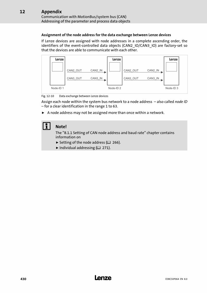
AppendixCommunication with MotionBus/system bus (CAN)Addressing of the parameter and process data objects
12
� 430 EDBCSXP064 EN 8.0
Assignment of the node address for the data exchange between Lenze devices
If Lenze devices are assigned with node addresses in a complete ascending order, theidentifiers of the event−controlled data objects (CAN2_IO/CAN3_IO) are factory−set sothat the devices are able to communicate with each other.
L
Node-ID 1
CAN2_OUT CAN2_IN
CAN3_OUT CAN3_IN
L
Node-ID 2
CAN2_OUT CAN2_IN
CAN3_OUT CAN3_IN
L
Node-ID 3
Fig. 12−10 Data exchange between Lenze devices
Assign each node within the system bus network to a node address ˘ also called node ID˘ for a clear identification in the range 1 to 63.
ƒ A node address may not be assigned more than once within a network.
� Note!
The "8.1.1 Setting of CAN node address and baud rate" chapter containsinformation on
ƒ Setting of the node address ( 266).
ƒ Individual addressing ( 271).

AppendixOverview of accessories
12
� 431EDBCSXP064 EN 8.0
12.4 Overview of accessories
The accessories are not included in the scope of supply. Lenze’s basic devices andaccessories are carefully matched to each other. With the basic device and the accessories,all components for a complete drive system are available. The component selection mustbe matched to the respective application.
12.4.1 Connector sets
To make purchasing easy, the connector sets are available as separate delivery units for theECS power supply, capacitor and axis modules:
ƒ ECSZE000X0B (connector set for ECS power supply modules)
ƒ ECSZK000X0B (connector set for ECS capacitor modules)
ƒ ECSZA000X0B (connector set for ECS axis modules)
12.4.2 Shield mounting kit
The shield mounting kit ECSZS000X0B001 contains components for reliable and quickfixing of the cable shields. The scope of supply includes:
ƒ Shield sheet for motor cable
ƒ Wire clamp for shield connection of motor cable
ƒ Wire clamp for shield connection of control cables
ƒ Wire clamp for shield connection of motor monitoring cable
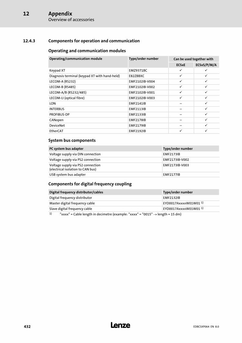
AppendixOverview of accessories
12
� 432 EDBCSXP064 EN 8.0
12.4.3 Components for operation and communication
Operating and communication modules
Operating/communication module Type/order number Can be used together with
ECSxE ECSxS/P/M/A
Keypad XT EMZ9371BC � �
Diagnosis terminal (keypad XT with hand−held) E82ZBBXC � �
LECOM−A (RS232) EMF2102IB−V004 � �
LECOM−B (RS485) EMF2102IB−V002 � �
LECOM−A/B (RS232/485) EMF2102IB−V001 � �
LECOM−LI (optical fibre) EMF2102IB−V003 � �
LON EMF2141IB ˘ �
INTERBUS EMF2113IB ˘ �
PROFIBUS−DP EMF2133IB ˘ �
CANopen EMF2178IB ˘ �
DeviceNet EMF2179IB ˘ �
EtherCAT EMF2192IB � �
System bus components
PC system bus adapter Type/order number
Voltage supply via DIN connection EMF2173IB
Voltage supply via PS2 connection EMF2173IB−V002
Voltage supply via PS2 connection(electrical isolation to CAN bus)
EMF2173IB−V003
USB system bus adapter EMF2177IB
Components for digital frequency coupling
Digital frequency distributor/cables Type/order number
Digital frequency distributor EMF2132IB
Master digital frequency cable EYD0017AxxxxW01W01 1)
Slave digital frequency cable EYD0017AxxxxW01W01 1)
1) "xxxx" = Cable length in decimetre (example: "xxxx" = "0015" � length = 15 dm)
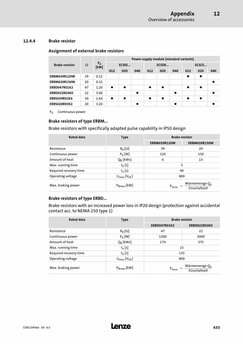
AppendixOverview of accessories
12
� 433EDBCSXP064 EN 8.0
12.4.4 Brake resistor
Assignment of external brake resistors
Brake resistor �Pd
[kW]
Power supply module (standard variants)
ECSEE... ECSDE... ECSCE...
012 020 040 012 020 040 012 020 040
ERBM039R120W 39 0.12 � �
ERBM020R150W 20 0.15 �
ERBD047R01K2 47 1.20 � � � � � �
ERBD022R03K0 22 3.00 � � �
ERBS039R01K6 39 1.64 � � � � � �
ERBS020R03K2 20 3.20 � � �
Pd Continuous power
Brake resistors of type ERBM...
Brake resistors with specifically adapted pulse capability in IP50 design
Rated data Type Brake resistor
ERBM039R120W ERBM020R150W
Resistance RB [Ω] 39 20
Continuous power Pd [W] 120 150
Amount of heat QB [kWs] 6 13
Max. running time te [s] 5
Required recovery time ta [s] 90
Operating voltage Umax [VDC] 800
Max. braking power PBmax [kW] PBmax� ��Wärmemenge�QB
Einschaltzeit
Brake resistors of type ERBD...
Brake resistors with an increased power loss in IP20 design (protection against accidentalcontact acc. to NEMA 250 type 1)
Rated data Type Brake resistor
ERBD047R01K2 ERBD022R03K0
Resistance RB [Ω] 47 22
Continuous power Pd [W] 1200 3000
Amount of heat QB [kWs] 174 375
Max. running time te [s] 15
Required recovery time ta [s] 135
Operating voltage Umax [VDC] 800
Max. braking power PBmax [kW] PBmax� ��Wärmemenge�QB
Einschaltzeit
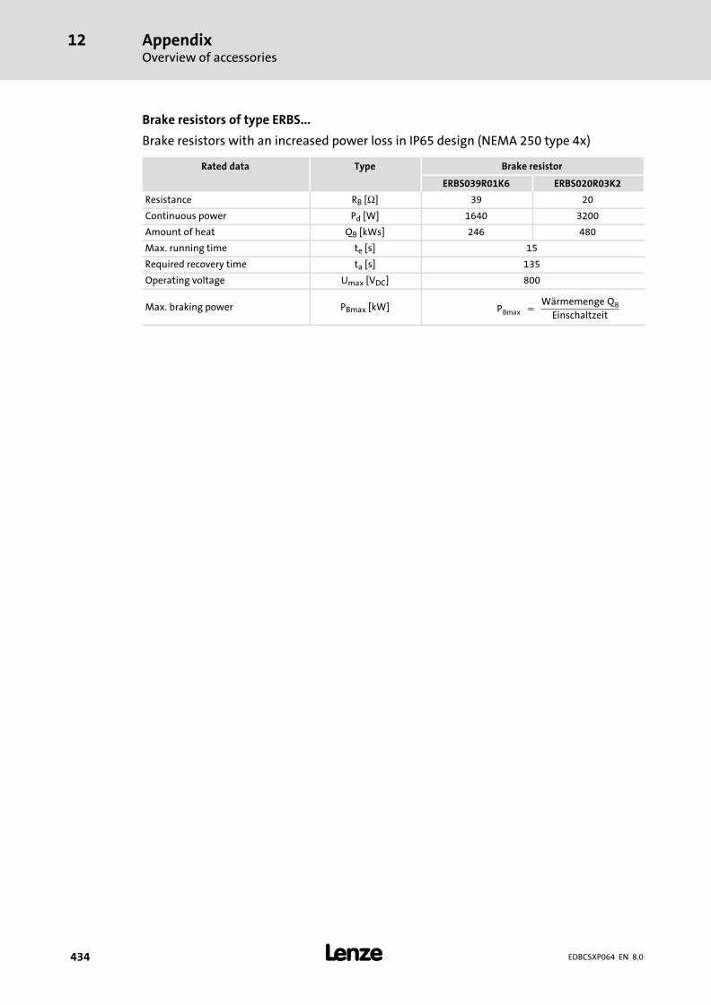
AppendixOverview of accessories
12
� 434 EDBCSXP064 EN 8.0
Brake resistors of type ERBS...
Brake resistors with an increased power loss in IP65 design (NEMA 250 type 4x)
Rated data Type Brake resistor
ERBS039R01K6 ERBS020R03K2
Resistance RB [Ω] 39 20
Continuous power Pd [W] 1640 3200
Amount of heat QB [kWs] 246 480
Max. running time te [s] 15
Required recovery time ta [s] 135
Operating voltage Umax [VDC] 800
Max. braking power PBmax [kW] PBmax� ��Wärmemenge�QB
Einschaltzeit

AppendixOverview of accessories
12
� 435EDBCSXP064 EN 8.0
12.4.5 Mains fuses
ƒ Mains fuses are not included in the Lenze delivery program. Use standard fuses.
ƒ When using ECSxE power supply modules which are fused on the supply side theDC−bus supply need not be fused.
ƒ When ECS axis modules are supplied by devices of the 82xx and 93xx series with acontinuous DC current > 40 A, install the following fuses between the supplyingdevice and the ECS devices:
Fuse Support
Value [A] Lenze type Lenze type
50 EFSGR0500ANIN EFH20007
ƒ Observe the national and regional regulations (VDE, UL, EVU, ...).
� Warnings!
ƒ Use UL−approved cables, fuses and fuse holders only.
ƒ UL fuse:– Voltage 500 ... 600 V– Tripping characteristic "H", "K5" or "CC"

AppendixOverview of accessories
12
� 436 EDBCSXP064 EN 8.0
12.4.6 Mains chokes
It is not mandatory to use a mains choke for operating the ECS modules. The respectiveapplication determines whether a mains choke is required or not.
Advantages when using a mains choke:
ƒ Lower system perturbations
– The waveform of the mains current is approximated to the sinusoidal shape.
– Reduction of the effective mains current by up to 25%.
– Reduction of the mains, cable and fuse load.
ƒ The effective DC−bus current also decreases by up to 25%.
ƒ Increased service life of the connected axis modules
– A mains choke reduces the AC current load of the DC−bus capacitors and thusincreases their service life.
ƒ Low−frequency radio interference voltages are reduced.
Please note:
ƒ With mains choke operation the maximally possible output voltage does not fullyreach the value of the mains voltage.
ƒ For operation of drives for accelerating duty with high peak currents, it isrecommended to use mains chokes with linear L/I characteristic (Lenze typesELN3...).
ƒ The choke rating is to be checked and adapted to the respective conditions.
Mains chokes for the power supply modules:
Power supply moduletype
Mains choke type Ir [A] Lr [mH]Short−circuitvoltage (Uk)
ECSxE012 ELN3−0150H024 3 x 24 3 x 1.5
4 %ECSxE020 ELN3−0088H035 3 x 35 3 x 0.88
ECSxE040 ELN3−0055H055 3 x 55 3 x 0.55

AppendixOverview of accessories
12
� 437EDBCSXP064 EN 8.0
12.4.7 RFI filters
According to the application, different measures for reducing the mains current and forradio interference suppression are required on the supply side for servo systems. As a rule,these measures are not mandatory, but protect the universal application of a servo system.
Lenze offers a built−on filter for each power supply module for the interference level A. TheRFI filters are designed for the ECS power supply module assigned and up to 10 axes witha motor cable length of 25 m each (Lenze system cable). The interference level A isobserved as long as the motor cable length per axis module is 25 m at a maximum (Lenzesytem cables) and the number of the ECS axis modules is maximally 10.
RFI filter type ECS power supply module type
ECSZZ020X4BECSxE012
ECSxE020
ECSZZ040X4B ECSxE040
Type of RFI filter U [V] I [A] Ploss [W] Weight [kg]
ECSZZ020X4B 3/PE AC 500 Vat 50 ... 60 Hz
16 6.23.0
ECSZZ040X4B 32 9.3
U Rated mains voltage
I Rated mains current
Ploss Power loss
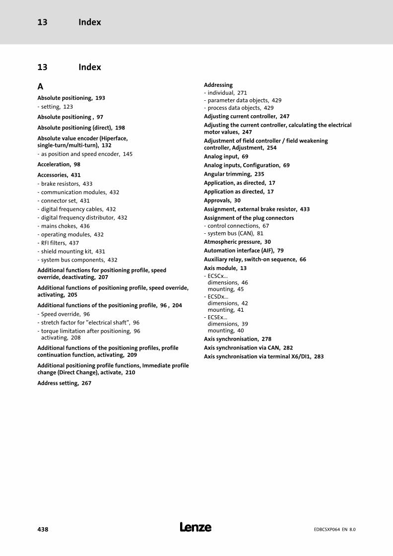
Index13
�438 EDBCSXP064 EN 8.0
13 Index
AAbsolute positioning, 193
− setting, 123
Absolute positioning , 97
Absolute positioning (direct), 198
Absolute value encoder (Hiperface,single−turn/multi−turn), 132
− as position and speed encoder, 145
Acceleration, 98
Accessories, 431
− brake resistors, 433
− communication modules, 432
− connector set, 431
− digital frequency cables, 432
− digital frequency distributor, 432
− mains chokes, 436
− operating modules, 432
− RFI filters, 437
− shield mounting kit, 431
− system bus components, 432
Additional functions for positioning profile, speedoverride, deactivating, 207
Additional functions of positioning profile, speed override,activating, 205
Additional functions of the positioning profile, 96 , 204
− Speed override, 96
− stretch factor for "electrical shaft", 96
− torque limitation after positioning, 96 activating, 208
Additional functions of the positioning profiles, profilecontinuation function, activating, 209
Additional positioning profile functions, Immediate profilechange (Direct Change), activate, 210
Address setting, 267
Addressing
− individual, 271 − parameter data objects, 429 − process data objects, 429
Adjusting current controller, 247
Adjusting the current controller, calculating the electricalmotor values, 247
Adjustment of field controller / field weakeningcontroller, Adjustment, 254
Analog input, 69
Analog inputs, Configuration, 69
Angular trimming, 235
Application, as directed, 17
Application as directed, 17
Approvals, 30
Assignment, external brake resistor, 433
Assignment of the plug connectors
− control connections, 67 − system bus (CAN), 81
Atmospheric pressure, 30
Automation interface (AIF), 79
Auxiliary relay, switch−on sequence, 66
Axis module, 13
− ECSCx...dimensions, 46 mounting, 45
− ECSDx...dimensions, 42 mounting, 41
− ECSEx...dimensions, 39 mounting, 40
Axis synchronisation, 278
Axis synchronisation via CAN, 282
Axis synchronisation via terminal X6/DI1, 283

Index 13
� 439EDBCSXP064 EN 8.0
BBasic identifier, 429
Basic settings with GDC, 117
Baud rate
− setting, 268 via DIP switch, 268
− system bus (CAN). Siehe baud rate
Brake, connection, 61
Brake configuration, 130
Brake resistor, external, 433
− assignment, 433
− connection, 59
− type ERBD..., rated data, 433
− type ERBM..., rated data, 433
− type ERBS..., rated data, 434
Brake resistor, internal, Connection, 57
Bus cable length, 83
Bus load CAN, 288
Bus off, 298
CCable cross−section, 83
Cable cross−sections
− Control connections, 54 , 67 − control connections, 52 − control terminals, connection "Safe torque off", 73
Cable specification, 81
Cables, shielded, 53
Cables, specification, motor cables, 60
CAN bus
− assignment of the plug connectors, 81 − boot−up time setting, 274 − communication, 412 − configuring, 266 − cyclic process data objects, synchronisation, 421 − data telegram, 412 − determining the master in the drive system, 273 − event−controlled process data objects, 422 − Guiding angle selection and synchronisation, 277 − identifier, 412 , 429
display code, 429 − individual addressing, 271 − making a reset node, 276 − network management data, 413 − parameter data, 413 , 423 − parameter data channels, 423 − parameter data objects, addressing, 429 − process data, 413
from the axis module, 161 to the axis module, 158
− process data objects, 417 addressing, 429 data transmission, 419
− process data telegrams, 418 − setting baud rate, 266 − setting delay time, 274 − setting node address, 266 − setting the cycle time, 274 − user data, 413 , 424
CAN bus load, 288
CAN bus status, 286
CAN data telegram, 412
CAN diagnostic codes, 286
CAN network
− communication phases, 414 − state transitions, 415 − statuses, 414
CAN network management (NMT), 416
CAN Sync correction increment, 279

Index13
�440 EDBCSXP064 EN 8.0
CAN sync identifiers, 280
CAN sync response, 281
CAN synchronisation, 278
CAN synchronisation cycle, 278
CAN telegram counter , 287
CAN user organisation CiA, Homepage, 413
Capacitor module, 13
Capacitor module ECSxK..., Connection, 63
Capacitor modules, 63
CE−typical drive system, 48
− assembly, 49
− earthing, 50
− filters, 49
− installation , 48
− shielding, 50 cables, 53
Charging current limitation, function selection, 126
COB−ID, 429
− display code, 429
Code descriptions, 14
Index 13
� 441EDBCSXP064 EN 8.0
Code table, 353
Commissioning, 92
− adjusting the current controller, calculating the electricalmotor values, 247
− Adjustment of field controller / field weakeningcontroller, 254
− Basic settings with GDC, 117 − basics of positioning, basic terms, 92 − before you start, 115 − commissioning steps, overview, 116 − configuration of digital inputs/outputs
inputs for continuous positioning axis, 170 inputs for linear positioning axis, 171 setting the polarity, 172
− configuring the digital inputs/outputs, 168 − configuring the electrical shaft, 211 − Control sequence for starting positioning profile, 226 − controller enable, 241 − current controller adjustment, metrological
determination of electrical motor values, 248 − defining the dwell time, 232 − Defining the positioning profile, setting of positioning
profile parameters, 201 − defining the positioning profile, additional functions of
the positioning profile, 96 , 204 − defining the window for standstill message, 231 − electrical shaft via digital frequency coupling, 215 − electrical shaft via EtherCAT, PLC as master, 224 − Electrical shaft via MotionBus (CAN), ECSxP as master,
217 − electrical shaft via MotionBus (CAN), PLC as master, 220 − entry of machine parameters, 165 − Entry of motor data, 128 − following error monitoring, 233 − holding brake configuration, 130 − limit positions and limit switches
evaluation of hardware limit switches, 240 manual control to hardware limit switch, 175 manual control to software limit position, 175 monitoring by software limit positions, 237 retracting from hardware limit switches, 176
− loading the Lenze settings, 125 − operation with motors of other manufacturers, 244 − Operation with servo motors from other manufacturers,
Motor feedback system − checking the direction ofrotation, 246
− operation with servo motors of other manufacturersadjusting current controller, 247 effecting rotor position adjustment, 249 entering motor data, 244
− Optimising the drive behaviour, 252 − Positioning profile modes, Electrical shaft ("E−shaft"),
196 − positioning profile modes
absolute positioning, 193 absolute positioning (direct), 198
absolute touch probe positioning, 194 continuous constant travel, 195 continuous constant travel (direct), 199 homing, 197 positioning sequence for controller optimisation, 200 relative positioning in the continuous measuring system,193 relative positioning in the continuous measuring system(direct), 198 relative positioning with absolute reference, 194 relative positioning with absolute reference (direct), 199 relative touch probe positioning in the continuousmeasuring system, 195 relative touch probe positioning with absolute reference,195 reset reference, 197 setting the reference, 197
− profile parameter jerk time, parameters, 202 − quick stop (QSP), 243 − Resolver adjustment, 257 − Select control interface, 155 − Select operating mode, 155 − selecting a positioning profile, selecting a positioning
profile mode, 191 − Selecting the function of the charging current limitation,
126 − set reference, 119 − setting absolute positioning, 123 − setting homing
reference search with continuous positioning axis, 189 reference search with linear positioning axis, 188
− setting of feedback systemabsolute value encoder, 146 SinCos encoder (single−turn, multi−turn), 146
− Setting of homing, 122 − setting of homing
parameters, 177 shifting of the zero position, 187
− setting of mains data, 126 − setting of manual control (inching mode)
manual control to hardware limit switch, 175 manual control to software limit position, 175 parameters, 173
− setting of manual jog (inching mode), retracting fromhardware limit switches, 176
− setting of the feedback system, 132 resolver as multi−turn absolute value encoder, 135
− setting relative positioning (continuous measuringsystem), 123
− setting the feedback systemabsolute value encoder (position encoder), resolver(speed encoder), 150 incremental encoder (TTL encoder), 136 resolver as position and speed encoder, 133 SinCos encoder, 136 TTL/SinCos encoder (position encoder), resolver (speedsensor), 140
− setting the homing, homing modes, 179 − setting the polarity of digital inputs/outputs, 172 − setting the positioning profile, 191
Index13
�442 EDBCSXP064 EN 8.0
− setting the target position window, 229
− setting the voltage threshold, 127
− Speed controller adjustment, 252
− speed−dependent angular trimming, 235
− state control, 110 operating states, 111 state change (transitions), 113
Communication modules, 432
Communication phases, 414
Configuration, 265
− axis synchronisation, 278 − Axis synchronisation (start), 279 − axis synchronisation via CAN, 282 − axis synchronisation via terminal X6/DI1, 283 − CAN bus load, 288 − CAN bus status, 286 − CAN diagnostic codes, 286 − CAN sync correction increment, 279 − CAN sync identifiers, 280 − CAN synchronisation, 278 − CAN synchronisation (start), 279 − CAN synchronisation cycle, 278 − CAN telegram counter , 287 − Code table, 353 − cyclic node monitoring (Node Guarding), 284 − monitoring, 291
current load of the motor (I2 x t monitoring), 22 , 309 voltage supply of control electronics, 316
− Monitoring functions, Motor temperature, 22 − monitoring functions
bus off, 298 current load of controller (I x t monitoring), 306 DC−bus voltage, 313 earth fault, 300 heatsink temperature, 303 max. system speed, 322 monitoring times for process data input objects, 297 motor phase failure, 316 motor temperature, 301 motor temperature sensor, 318 overview, 292 Resolver cable, 317 rotor position adjustment, 323 short circuit, 300 sin/cos signal, 320 speed system deviation, 321 temperature inside the controller, 304 thermal sensors, 305
− monitoring of the synchronisation, 281 − MotionBus (CAN)
boot−up time setting, 274 making a reset node, 276 setting the baud rate, 266 setting the node address, 266
− Sync phase displacement, 278 − sync phase displacement, correction value, 279 − system bus (CAN)
determining the master in the drive system, 273 individual addressing, 271 setting delay time, 274 setting the baud rate, 266 setting the cycle time, 274 setting the node address, 266
− Thermal motor monitoring, 22 − via automation interface (AIF), 265 − via system bus interface, 265
Index 13
� 443EDBCSXP064 EN 8.0
Configuration of CAN interface, node address (node ID),430
Configuration of digital inputs/outputs
− inputs for continuous positioning axis, 170
− inputs for linear positioning axis, 171
Configuring CAN interface, monitoring, timeout withactivated remote parameterisation, 299
Conformity, 30
Connection
− Capacitor module ECSxK..., 63
− DC bus, 52 , 54
− external brake resistor, 59
− Internal brake resistor, 57
− motor, 52
− motor holding brake, 52 , 61
Connection "Safe torque off", terminals, 73
Connection "safe torque off", 70
− functional description, 71
− Important notes, 72
connection "safe torque off", Important notes, 72
Connection of "safe torque off"
− function check, 74
− implementation, 70
− technical data, 73
Continuous constant travel, 195
Continuous constant travel (direct), 199
Control connections
− Analog inputs, configuration, 69
− assignment of the plug connectors, 67
− Cable cross−sections, 54 , 67
− cable cross−sections, 52
− Digital inputs, 68
− Digital outputs, 68
− Tightening torques, 54 , 67
− tightening torques, 52
Control factor, 34
Control sequence for starting positioning profile, 226
Control signals, 65
Control terminals, 64
− cable cross−sections, connection "Safe torque off", 73
− starting torques, connection "Safe torque off", 73
Control word Ctrl1, 159 , 160
Control/signal cables, shield connection, 65
Controller, 13
− application as directed, 17
− identification, 17
Controller enable, 241
controller enable, 241
Controller inhibit (CINH), 241
Current characteristics
− application example, 36
− device protection by current derating, 37
− rated output current, 34
Current controller adjustment, metrologicaldetermination of electrical motor values, 248
Current derating, 37
Current load of controller, I x t monitoring, 306
Current load of the motor, I2 x t monitoring, 22 , 309
Cyclic node monitoring (Node Guarding), 284
Cyclic process data objects, 420
DData telegram, 412
Data words, from the axis module, 164
Data, general electrical, 31
DC bus
− connection, 52 , 54
− fuses, 55 , 435
DC−bus voltage
− monitoring functions, 313
− overvoltage, 313
− undervoltage, 313
DC−bus voltage monitoring (OU, LU), 313
Deceleration, 98
Defining boot−up master, 273
Defining master in the drive system, 273
Defining the dwell time, 232
Defining the window for standstill message, 231
Definition of notes used, 29
Definitions of terms, 13
Device protection, 26
Device protection by current derating, 37
Device status, 163
device status, 163 , 340
Device structure, 108
Diagnostics, 324
− with Global Drive Control (GDC), 324
− with Global Drive Oscilloscope (GDO), 326 Diagnostics with GDO, 328 GDO buttons, 327
− with PCAN−View, 334
− with XT EMZ9371BC keypad, 333

Index13
�444 EDBCSXP064 EN 8.0
Diagnostics codes, 286
Digital frequency cables, 432
Digital frequency distributor, 432
Digital frequency input, 90
− features, 90
Digital frequency output, 90
− features, 90
Digital inputs, 68
− configuring, 168
− setting the polarity, 172
Digital outputs, 68
− configuring, 168
− setting the polarity, 172
Dimensions, 39 , 42 , 46
− axis module ECSCx..., 46
− axis module ECSDx..., 42
− axis module ECSEx..., 39
DIP switch, 267
Direct Change, activate, 210
Direct positioning, 198
Discharge current to PE, 31
Disposal, 21
Drive system, 13
Dwell time, 232
EEarth fault monitoring (OC2), 300
Earth−fault monitoring, 300
Earthing, EMC, 50
Effecting rotor position adjustment, 249
Electrical installation, 48
− connection "Safe torque off", terminals, 73 − connection "safe torque off", 70
functional description, 71 Important notes, 72
− connection of "safe torque off"function check, 74 implementation, 70 technical data, 73
− Connection of capacitor module ECSxK..., 63 − control connections, 64
assignment of the plug connectors, 67 Digital inputs, 68 Digital outputs, 68
− control terminals, 65 − feedback system, 85
encoder, 87 resolver, 86
− installation of a CE−typical drive system, 48 assembly, 49 earthing, 50 filters, 49 shielding, 50
− power connections, 52 connection of external brake resistor, 59 DC bus connection, 52 internal brake resistor connection, 57 motor connection, 52 , 60 motor holding brake connection, 52 plug connector assignment, 52
− power terminalsconnection of motor holding brake, 61 DC bus connection, 54
− specification of the cables, motor cables, 60
Electrical shaft
− configuring, 211 − stretch factor, 212 − via digital frequency coupling, 215 − via EtherCAT, PLC as master, 224 − via MotionBus (CAN)
ECSxP as master, 217 PLC as master, 220
Electrical shaft ("E−shaft"), 196
Electrical shaft ("EShaft"), 107
Electromagnetic compatibility, 31
Index 13
� 445EDBCSXP064 EN 8.0
EMC, 31
− earthing, 50
− filters, 49
− shielding, 50 cables, 53
EMF2131IB digital frequency distributor, wire, 91
EMF2131IB digital frequency distributor , wire, 91
Enclosure, 31
Encoder, 87
− Absolute value encoder (Hiperface,single−turn/multi−turn), as position and speed encoder,145
− absolute value encoder (Hiperface,single−turn/multi−turn), 132
− incremental encoder (TTL encoder), 88
− SinCos absolute value encoder, 89
− SinCos encoder, 89 absolute value encoder (Hiperface,single−turn/multi−turn), 132
− supply voltage, 87
Encoder simulation, 90
Entering motor data, 244
Entry of machine parameters, 165
Entry of motor data, 128
Environmental conditions, 30
− atmospheric pressure, 30
− pollution, 30
− site altitude, 30
− temperature, 30
− vibration resistance, 30
Error analysis, 337
− Via history buffer, 338
− via LECOM status word, 340
Error messages, 426
− Causes and remedies, 343
− causes and remedies, 343
− configuration, 293
− reset (TRIP−RESET), 352
Error response, 425
Evaluation of hardware limit switches, 240
Event−controlled process data objects, 422
Examples
− reading parameters, 427
− Selection help for cable length / number of repeaters, 84
− writing parameters, 428
Executing a reset node, 276
Explanations, Code table, 353
External brake resistor, 433
− assignment, 433
− connection, 59
− type ERBD..., rated data, 433
− type ERBM..., rated data, 433
− type ERBS..., rated data, 434
FFAIL−QSP, 292
Fault analysis, 337
− Via history buffer, 338
− via LECOM status word, 340
− via LEDs, 337
− with keypad XT EMZ9371BC, 337
Fault message, reset, 339
Fault messages, 343
− causes and remedies, 343
− configuration, 293
− reset (TRIP−RESET), 352
Fault responses, 292
Feed constant, 105
Feedback system, wiring, 85
− encoder, 87
− incremental encoder (TTL encoder), 88
− resolver, 86
− SinCos absolute value encoder, 89
− SinCos encoder, 89
Field controller / field weakening controller, 254
Filters, EMC, 49
Final speed, 98
Following errors, monitoring, 233
Free space, 30
Function monitoring of thermal sensors (H10, H11), 305
Functional earth conductor, 44
Fuses, 55 , 435
− DC bus, 55 , 435
− replacing, 55
Index13
�446 EDBCSXP064 EN 8.0
GGateway function, 289
Gearbox ratio, 104
Global Drive Control (GDC)
− Diagnostics, 324
− Parameter setting, 259
Global Drive Oscilloscope (GDO), 326
− Diagnostics with GDO, 328
− GDO buttons, 327
Guiding angle default and synchronisation, CAN syncresponse, 281
Guiding angle selection and synchronisation, viaMotionBus (CAN), 277
HHardware limit switches
− evaluation, 240
− manual control to, 175
− retracting, 176
Heatsink temperature, monitoring functions, 303
Heatsink temperature monitoring (OH, OH4), 303
History buffer, 338
− codes, 339
− deleting entries, 339
− fault message reset, 339
Holding brake configuration, 130
Homing, 101 , 112 , 197
Homing Modes, 179
Homing modes, 179
− modes 0 and 1, 179
− modes 6 and 7, 182
− modes 10 and 11, 184
− modes 12 and 13, 185
− modes 14 and 15, 186
− modes 2 and 3, 180
− modes 4 and 5, 182
− modes 8 and 9, 183
IIdentification, controller, 17
Identifier, 412 , 429
identifier, display code, 429
Immediate profile change (Direct Change), activate, 210
Inching mode (manual jog), setting, 101 , 121
Incremental encoder, as position and speed encoder, 136
Incremental encoder (TTL encoder), 88
Individual addressing, 271
Init, 111
Installation, 30
− system bus (CAN), 80
Installation of a CE−typical drive system, 48
− assembly, 49 − earthing, 50 − filters, 49 − shielding, 50
cables, 53
Installation, electrical, 48
− connection "Safe torque off", terminals, 73 − connection "safe torque off", 70
functional description, 71 Important notes, 72
− connection of "safe torque off"function check, 74 implementation, 70 technical data, 73
− Connection of capacitor module ECSxK..., 63 − control connections, 64
assignment of the plug connectors, 67 Digital inputs, 68 Digital outputs, 68
− control terminals, 65 − feedback system, 85
encoder, 87 resolver, 86
− installation of a CE−typical drive system, 48 assembly, 49 earthing, 50 filters, 49 shielding, 50
− power connections, 52 connection of external brake resistor, 59 DC bus connection, 52 internal brake resistor connection, 57 motor connection, 52 , 60 motor holding brake connection, 52 plug connector assignment, 52
− power terminalsconnection of motor holding brake, 61 DC bus connection, 54
− specification of the cables, motor cables, 60
Index 13
� 447EDBCSXP064 EN 8.0
Installation, mechanical, 38
− push−through technique (ECSDx...), 41
Installation, mechanical
− cold−plate technique (ECSCx...), 45
− important notes, 38
− with fixing rails (ECSEx...), 40
Insulation resistance, 31
InTarget, 229
Interfaces to the control, 108
Internal brake resistor, Connection, 57
JJerk time, 99
Jitter, 278 , 279
KKeypad XT EMZ9371BC
− changing and saving parameters, 264
− connecting the keypad, 260
− display elements, 261
− fault analysis, 337
− function keys, 263
LL−profile, 99
LECOM, status word (C0150/C0155), 340
LEDs, 337
Legal regulations, 17
Liability, 17
Limit positions and limit switches
− hardware limit switches, 107 evaluation, 240 manual control to, 175 retracting, 176
− software limit positions, 107 manual control to, 175 monitoring, 237
Loading the Lenze setting, 125
Low−voltage supply, 13
MMachine parameters, 103
− feed constant, 105
− gearbox ratio, 104
− max. acceleration/deceleration, 106
− motor revolutions, 103
− software limit positions, 107
− target position selection, maximum, 106
− traversing speed, maximum, 106
machine parameters, position resolution, 106
Mains fuses, 435
Malfunction of drive, 342
Manual jog (inching mode), setting, 101 , 121
ManualJog, 112
Manufacturer, 17
Max. acceleration/deceleration, 106
Max. system speed, monitoring functions, 322
MCTRL_MotorControl (motor control), monitoring,absolute value encoder initialisation, 319
Measuring system for positioning, 102
Mechanical installation, 38
− cold−plate technique (ECSCx...), 45
− important notes, 38
− push−through technique (ECSDx...), 41
− with fixing rails (ECSEx...), 40
Message, 292
Modes for homing
− modes 0 and 1, 179
− modes 6 and 7, 182
− modes 14 and 15, 186
− modes 4 and 5, 182
− modes 8 and 9, 183

Index13
�448 EDBCSXP064 EN 8.0
Monitoring
− absolute value encoder initialisation, 319
− by software limit positions, 237
− CAN interface, timeout with activated remoteparameterisation, 299
− current load of the motor, I2 x t monitoring, 22 , 309
− FAIL−QSP, 292
− message, 292
− Monitoring times for process data input objects, 297
− of following errors, 233
− speed−dependent angular trimming, 235
− voltage supply of control electronics, 316
− warning, 292
Monitoring functions, 291
− bus off, 298
− configuring, 297
− current load of controller, I x t monitoring, 306
− DC−bus voltage, 313
− earth fault, 300
− heatsink temperature, 303
− max. system speed, 322
− motor phase failure, 316
− Motor temperature, 22
− motor temperature, 301
− motor temperature sensor, 318
− Overview, 293
− Resolver cable, 317
− rotor position adjustment, 323
− short circuit, 300
− sin/cos signal, 320
− speed system deviation, 321
− temperature inside the controller, 304
− thermal sensors, 305
Monitoring of internal device temperature (OH1, OH5),304
Monitoring of the synchronisation, 281
Monitoring times for process data input objects, 297
Monitorings
− configuration, 293
− possible fault responses, 293
MotionBus (CAN), 412
− boot−up time setting, 274 − CAN data telegram, 412 − communication, 412 − configuring, 266 − cyclic process data objects, synchronisation, 421 − event−controlled process data objects, 422 − identifier, 412 , 429 − making a reset node, 276 − network management data, 413 − parameter data, 413 , 423 − parameter data channels, 423 − parameter data objects, addressing, 429 − process data, 413 − process data objects, 417
addressing, 429 data transmission, 419
− process data telegrams, 418 − setting the baud rate, 266 − setting the node address, 266 − user data, 413 , 424
Motor, connection, 52 , 60
motor, Thermal monitoring, Sensorless, 22
Motor cable length, 30
Motor cables, specification, 60
Motor feedback system, Checking the direction ofrotation, 246
Motor holding brake, connection, 52
Motor monitoring, 22
Motor phase failure, monitoring functions, 316
Motor protection, 27
Motor revolutions, 103
Motor temperature, monitoring functions, 301
Motor temperature monitoring (OH3, OH7), 301
Motor temperature sensor, monitoring, 318
Motor temperature sensor monitoring (Sd6), 318
Motor, connection, , 60
Motors of other manufacturers, 244
Mounting
− axis module ECSCx..., 45 − axis module ECSDx..., 41 − axis module ECSEx..., 40 − cold−plate design, 45 − standard installation (with fixing rails), 39 − thermally separated (push−through technique), 41
Mounting position, 30
Index 13
� 449EDBCSXP064 EN 8.0
NNetwork management (NMT), 416
Network management data, 413
Node address (node ID), CAN interface, 430
Node address setting, 267
Node guarding, 284
Node ID, 429
Node−ID, display code, 429
Noise emission, 31
Noise immunity, 31
Notes, definition, 29
OOffset selection, 187
Operating conditions, 30
Operating modules, 432
Operating states, 111
− Homing, 112
− Init, 111
− ManualJog, 112
− PosFunctions, 111
− Positioning, 112
− Stand−by, 111
− state change (transitions), 113
− Trouble, 111
Operation with motors of other manufacturers, 244
Operation with servo motors from other manufacturers
− Checking the direction of rotation of the motor feedbacksystem, 246
− current controller adjustment, metrologicaldetermination of electrical motor values, 248
Operation with servo motors of other manufacturers
− adjusting current controller, 247
− adjusting the current controller, calculating the electricalmotor values, 247
− effecting rotor position adjustment, 249
− entering motor data, 244
Optimising the drive behaviour, 252
Overcurrent characteristic, 307
Overcurrent diagram, 307
Override (speed variation), 96
− activating, 205
− deactivating, 207
Overvoltage threshold, DC−bus voltage, 313
PPackaging, 30
Parameter data, 413 , 423
Parameter data objects, addressing, 429
Parameter data telegram, 424
− examples, 427
Parameter data transfer, 423
Parameter setting, 258
− With Global Drive Control (GDC), 259
− with keypad XT EMZ9371BCchanging and saving parameters, 264 connecting the keypad, 260 keypad display elements, 261 keypad function keys, 263
− With XT EMZ9371BC keypad, 260
Parameters
− changing and saving, with keypad XT EMZ9371BC, 264
− for homing, 177
− for manual control (inching mode), 173
− for profile parameter jerk time, 202
− machine parameters, 103 , 165
− positioning profile parameters, 97 setting, 201
PC system bus adapter, 432
PCAN−View, diagnostics, 334
Phase displacement, correction value, 279
Phase shift, 278
Plug connector assignment, power connections, 52
Plug connectors
− control connections, 67
− power connections, 52
"Point−to−point" positioning, 193
Polarity of digital inputs/outputs, 172
Pollution, 30
PosFunctions, 111
Position control, feedback system, 132
− absolute value encoder, 146
− Absolute value encoder (position encoder), resolver(speed encoder), 150
− incremental encoder (TTL encoder), 136
− resolver, 133
− resolver as multi−turn absolute value encoder, 135
− SinCos encoder, 136
− SinCos encoder (single−turn, multi−turn), 146
− TTL/SinCos encoder (position encoder), resolver (speedencoder), 140
Position resolution, 106

Index13
�450 EDBCSXP064 EN 8.0
Positioning, 92 , 112
− "point−to−point" positioning, 193
− Basic termsProfile continuation after profile abort, 96 Speed variation (override), 96
− basic terms, 92 stretch factor for "electrical shaft", 96 torque limitation after positioning, 96 touch probe positioning, 93
− continuous constant travel, 195
− direct positioning, 198
− Electrical shaft ("E−shaft"), 196
− homing, 197
− positioning sequence for controller optimisation, 200
− relative positioning in the continuous measuring system,97
− relative positioning with absolute reference, 97
− state control, operating states, 111
− States of the positioning driveInit, 111 Stand−by, 111
− states of the positioning driveHoming, 112 ManualJog, 112 PosFunctions, 111 Positioning, 112 Trouble, 111
− touch probe positioning, 194
Positioning , absolute positioning , 97
Positioning profile mode, selecting, 191
Positioning profile, 94
Positioning profile additional features, Profilecontinuation function, Activate, 96
Positioning profile mode, 95
Positioning profile modes
− absolute positioning, 193
− absolute positioning (direct), 198
− continuous constant travel, 195
− continuous constant travel (direct), 199
− Electrical shaft ("E−shaft"), 196
− homing, 197
− positioning sequence for controller optimisation, 200
− relative positioning in the continuous measuring system,193
− relative positioning in the continuous measuring system(direct), 198
− relative positioning with absolute reference, 194
− relative positioning with absolute reference (direct), 199
− reset reference, 197
− setting the reference, 197
− touch probe positioningabsolute , 194 relative in the continuous measuring system, 195 relative with absolute reference, 195
Positioning profile parameters, 97
− acceleration, 98
− deceleration, 98
− final speed, 98
− jerk time, 99
− setting, 201
− target position, 97
− traversing speed, 98
Positioning sequence for controller optimisation, 200
Power connections, 52
− connection of external brake resistor, 59
− DC bus connection, 52
− Internal brake resistor connection, 57
− motor connection, 52 , 60
− motor holding brake connection, 52
− plug connector assignment, 52
Power reduction, 30
Power supply module, 13
Power terminals, 51
− connection of motor holding brake, 61
− DC bus connection, 54
Process data, 413
− from the axis module, 161 data words, 164
− of the axis module, device status, 163
− structure, 418
− to the axis module, 158 control word Ctrl1, 159 , 160
Process data objects
− addressing, 429
− available, 417
− cyclic, 420
− event−controlled, 422
− transfer, 419
Process data telegram, 418
Process data transfer, 417
Profile continuation function
− Activate, 96
− activating, 209
Protection of persons, 26
Protective insulation, 31
Protective measures, 31
Protective separation, 31
Index 13
� 451EDBCSXP064 EN 8.0
QQuick stop (QSP), 243
RRated data, 32 , 33
− external brake resistortype ERBD..., 433 type ERBM..., 433 type ERBS..., 434
Rated output current, 34
Reference search with continuous positioning axis, 189
Reference search with linear positioning axis, 188
Relative positioning
− in the continuous measuring system, 97
− with absolute reference, 97
Relative positioning (continuous measuring system),setting, 123
Relative positioning in the continuous measuring system,193
Relative positioning in the continuous measuring system(direct), 198
Relative positioning with absolute reference, 194
Relative positioning with absolute reference (direct), 199
Remote parameterisation (gateway function), 289
Reset HomePosAvailable, 197
Reset reference, 197
Residual hazards, 26
Resolver, 86 , 257
− Adjustment, 257
− as position and speed encoder, 133
− setting as absolute value encoder, 135
Resolver cable, monitoring, 317
Responses, 292
− CAN sync response, 281
Rotor position adjustment, monitoring, 323
SS−profile, 99
Safe standstill, 70
Safe torque off, 70
Safety instructions, 18
− definition, 29 − layout, 29
Sd7 − absolute value encoder initialisation, 319
Select control interface, 155
Select operating mode, 155
Selection help for cable length / number of repeaters,Example, 84
Set homing, homing modes
− modes 14 and 15, 186 − modes 8 and 9, 183
Set reference, 119
Setting a reference, 101
Setting homing
− homing modesmodes 0 and 1, 179 modes 6 and 7, 182 modes 4 and 5, 182
− parameters, 177 − reference search with continuous positioning axis, 189 − reference search with linear positioning axis, 188
Setting node address, 266
Setting of boot up time , 274
Setting of cycle time, 274
Setting of feedback system
− absolute value encoder, 146 − SinCos encoder (single−turn, multi−turn), 146
Setting of homing, 122
− shifting of the zero position, 187
Setting of mains data, 126
Setting of manual control (inching mode)
− manual control to hardware limit switch, 175 − manual control to software limit position, 175 − parameters, 173
Setting of manual jog (inching mode), retracting fromhardware limit switches, 176
Setting of the feedback system, 132
− resolver as multi−turn absolute value encoder, 135
Setting the address, via DIP switch, 267
Setting the baud rate, 266
Index13
�452 EDBCSXP064 EN 8.0
Setting the feedback system
− absolute value encoder (position encoder), resolver(speed encoder), 150
− incremental encoder (TTL encoder), 136
− Resolver as position and speed encoder, 133
− SinCos encoder, 136
− TTL−/SinCos encoder (position encoder), resolver (speedsensor), 140
Setting the homing, homing modes, 179
− modes 10 and 11, 184
− modes 12 and 13, 185
− modes 2 and 3, 180
Setting the jerk time, parameters, 202
Setting the node address, via DIP switch, 267
Setting the polarity, digital inputs/outputs, 172
Setting the positioning profile, 191
Setting the reference, 197
Setting the target position window, 229
Setting the voltage thresholds, 127
Shield connection, control/signal cables, 65
Shielded cables, 53
Shielding
− cables, 53
− EMC, 50
Shifting the zero position (offset selection), 187
Short circuit monitoring (OC1), 300
Short−circuit monitoring, 300
Sin/cos signal, monitoring functions, 320
Sin/cos signal monitoring (Sd8), 320
SinCos absolute value encoder, 89
SinCos encoder, 89
− without serial communication, as position and speedencoder, 136
Site altitude, 30
Software limit positions, 107
− manual control to, 175
− monitoring, 237
Specification of the cables, motor cables, 60
Specification of the transmission cable, 81
Speed control, feedback system, 132
− absolute value encoder, 146
− Absolute value encoder (position encoder), resolver(speed encoder), 150
− incremental encoder (TTL encoder), 136
− resolver, 133
− resolver as multi−turn absolute value encoder, 135
− SinCos encoder, 136
− SinCos encoder (single−turn, multi−turn), 146
− TTL/SinCos encoder (position encoder), resolver (speedencoder), 140
Speed controller, 252
− Adjustment, 252
Speed override, 96
− activating, 205
− deactivating, 207
Speed system deviation, monitoring functions, 321
Speed−dependent angular trimming, 235
Stand−by, 111
Standards, 30
Standstill message, defining window, 231
Starting torques, control terminals, connection "Safetorque off", 73
State change (transitions), 113
State control, 110
− operating stated, 111
− state change (transitions), 113
Status CAN, 286
status of the axis module, 163 , 340
Status word, LECOM (C0150/C0155), 340
Status word 1 (Stat1), 161
Status word 2 (Stat2), 161
Statuses, CAN network, 414
Stretch factor, 212
Stretch factor for "electrical shaft", 96
Structure of the process data, 418
Supply voltage, encoder, 87
Switch−off thresholds, 314
Switch−on thresholds, 314
Sync correction increment, 279

Index 13
� 453EDBCSXP064 EN 8.0
Sync identifiers, 280
Sync phase displacement, 278
− correction value, 279
Sync signal source, 278
Sync telegram, 421
Synchronisation
− CAN sync response, 281
− cyclic process data objects, 421
Synchronisation cycle, 278
Synchronisation via CAN, 282
Synchronisation via terminal X6/DI1, 283
System bus (CAN), 411 , 412
− assignment of the plug connectors, 81
− baud rate, 83 , 84
− communication, 412
− configuring, 266
− cyclic process data objects, synchronisation, 421
− determining the master in the drive system, 273
− event−controlled process data objects, 422
− identifier, 412 , 429
− individual addressing, 271
− network management data, 413
− parameter data, 413 , 423
− parameter data channels, 423
− process data, 413
− process data objects, 417 addressing, 429 data transmission, 419
− process data telegrams, 418
− setting delay time, 274
− setting the baud rate, 266
− setting the cycle time, 274
− setting the node address, 266
− user data, 413 , 424
− wiring, 80 , 82
system bus (CAN)
− CAN data telegram, 412
− parameter data objects, addressing, 429
System bus components, 432
System error messages, Causes and remedies, 343
TTarget position, 97
− setting the target position window, 229
Target position selection, maximum, 106
Technical data, 30
− current characteristicsapplication example, 36 device protection by current derating, 37 rated output current, 34
− external brake resistortype ERBD..., 433 type ERBM..., 433 type ERBS..., 434
− general electrical data, 31 − rated data, 32 , 33 − standards and operating conditions, 30
Telegram counter CAN, 287
Temperature, 30
Temperature inside the controller, monitoring functions,304
Terminology used, 13
Thermal monitoring, motor, Sensorless, 22
Thermal sensors, monitoring functions, 305
Thermal separation, 41
Tightening torques
− Control connections, 54 , 67 − control connections, 52
Time−out monitoring for activated remoteparameterisation, 299
Timeout with activated remote parameterisation, CANinterface, 299
Torque, safe torque off, 70
Torque limitation after positioning, 96
− activating, 208
Touch probe positioning, 93 , 194
− absolute TP positioning, 194 − relative touch probe positioning in the continuous
measuring system, 195 − relative with absolute reference, 195
Transmission cable, specification, 81
Traversing speed, 98
Traversing speed, maximum, 106
TRIP, 292
TRIP−RESET, 339 , 352
Trouble, 111

Index13
�454 EDBCSXP064 EN 8.0
Troubleshooting
− fault messages, 343
− malfunction of drive, 342
Troubleshooting and fault elimination, 337
− monitoringcurrent load of the motor (I2 x t monitoring), 22 , 309 voltage supply of control electronics, 316
− monitoring functionsbus off, 298 current load of controller (I x t monitoring), 306 DC−bus voltage, 313 earth fault, 300 heatsink temperature, 303 max. system speed, 322 monitoring times for process data input objects, 297 motor phase failure, 316 motor temperature, 301 motor temperature sensor, 318 Resolver cable, 317 rotor position adjustment, 323 short circuit, 300 sin/cos signal, 320 speed system deviation, 321 temperature inside the controller, 304 thermal sensors, 305
TTL encoder, 88
TTL incremental encoder, as position and speed encoder,136
UUndervoltage threshold, DC−bus voltage, 313
User data, 413 , 424 , 426
VVibration resistance, 30
Virtual gearbox, stretch factor, 212
Voltage supply of control electronics, monitoring, 316
WWarning, 292
Warranty, 17
Wiring, system bus (CAN), 82
XXT EMZ9371BC keypad, Diagnostics, 333
ZZero position
− defining (homing), 101 , 119
− shifting (offset selection), 187

0 1© 07/2013
� Lenze Automation GmbHHans−Lenze−Str. 1D−31855 AerzenGermany
Service Lenze Service GmbHBreslauer Straße 3D−32699 ExtertalGermany
� +49�(0)51 54 /�82−0 � 00�80�00�/ 24�4�68�77 (24 h helpline)
� +49�(0)51 54 /�82 − 28 00 � +49�(0)51�54�/ 82−11 12
� [email protected] � [email protected]
� www.Lenze.com
EDBCSXP064 � .LKr � EN � 8.0 � TD17
10 9 8 7 6 5 4 3 2 1