operating instructions en mode d’emploi fr … instructions en mode d’emploi fr manual de...
TRANSCRIPT

Operating instructions enMode d’emploi frManual de instrucciones esManual de instruções pt
DD 200
Printed: 22.11.2013 | Doc-Nr: PUB / 5145575 / 000 / 01

1 932
13
14
22
23
28
7
9
26
14
15
28
41 42 40
43 16
18
17
31
39
19
29
27
25
29
24
21
2030
33
10
6
5
2 4
8
3
1112
34
38 37 36 35
Printed: 22.11.2013 | Doc-Nr: PUB / 5145575 / 000 / 01

This Product is CertifiedCe produit est certifié
Este producto esta certificadoEste produto está certificado
C US
Printed: 22.11.2013 | Doc-Nr: PUB / 5145575 / 000 / 01
2
2
4
3
5
6
3
7
3
21/3
1
2 1
4/62
5
31
2
56
88
7
965
1/12
11
3104 2
6
1/32
1/3
312
Printed: 22.11.2013 | Doc-Nr: PUB / 5145575 / 000 / 01
9
11
8
10
12
3
5
2/4
13
5
2/4
1
5 1/3
4 6 2
12/43
1
2
13 64/5
2
3
1
Printed: 22.11.2013 | Doc-Nr: PUB / 5145575 / 000 / 01
15
17
14
16
18
6 24/5
3
1
8
1
46/7
5
3
2
52
6
4
3
1
2
5 3/4/61
1/3
2
Printed: 22.11.2013 | Doc-Nr: PUB / 5145575 / 000 / 01

1
enIt is essential that the operating instructionsare read before the machine is operated forthe first time.
Always keep these operating instructionstogether with the machine.
Ensure that the operating instructions arewith the machine when it is given to otherpersons.
ORIGINAL OPERATING INSTRUCTIONS
DD 200 diamond core drilling system
Contents Page1. General information 12. General safety rules 33. Specific safety rules and symbols 44. Functional description 55. Technical data 56. Before use 67. Operation 98. Care and maintenance 119. Tools and accessories 12
10. Troubleshooting 1211. Disposal 1412. Manufacturer's warranty – tools 14
Operating controls, parts and indicators Drilling rig (drive unit and drill stand) �
Drive unit; Service indicator= Drilling performance indicator% On / off switch& Gear selector switch( Water flow regulator) Chuck+ Supply cord with GFCI§ Carrying grips (2)/ Water hose connector: Type plate· Interface
Drill stand$ Column£ End cap| Strut¡ Base plateQ Clamping spindleW Clamping nutE AnchorR Leveling screws
T Hole center indicatorZ CarriageU Drive unit (eccentric) locking boltI Direct driveO Reduction gearP Carriage locking mechanismÜ Hand wheel[ Carrying grip] Supply cord guideÆ Type plateº Leveling indicators (2)• End stopA Wheel assembly mounting point
ACCESSORIESVacuum base plateS Pressure gaugeD Vacuum release valveF Vacuum sealG Vacuum hose connectorH Wheel assembly mounting point
Water flow indicatorJ Water flow indicator
Water collector systemK Water collector holderL Water collectorÖ SealÄ Seal
1. General information1.1 Safety notices and their meaning
-DANGER-Draws attention to imminent danger that will lead to seri-ous bodily injury or fatality.
-WARNING-Draws attention to a potentially dangerous situation thatcould lead to serious personal injury or fatality.
-CAUTION-Draws attention to a potentially dangerous situation thatcould lead to slight personal injury or damage to theequipment or other property.
-NOTE-Draws attention to an instruction or other useful infor-mation.
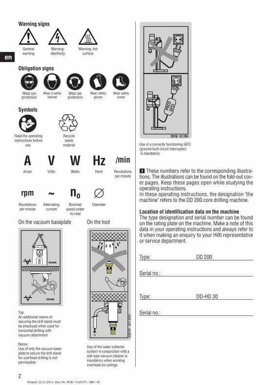
Prohibition signs1.2 Pictograms
Transport bycrane is notpermissible.
Printed: 22.11.2013 | Doc-Nr: PUB / 5145575 / 000 / 01
2
en
On the vacuum baseplate On the tool
VACUUM
VACUUM
Top:An additional means of securing the drill stand mustbe employed when used forhorizontal drilling with vacuum attachment.
Below:Use of only the vacuum base-plate to secure the drill standfor overhead drilling is not permissible.
Use of the water collector system in conjunction with awet-type vacuum cleaner ismandatory when workingoverhead on ceilings.
� These numbers refer to the corresponding illustra-tions. The illustrations can be found on the fold-out cov-er pages. Keep these pages open while studying theoperating instructions.In these operating instructions, the designation "themachine" refers to the DD 200 core drilling machine.
Location of identification data on the machineThe type designation and serial number can be foundon the rating plate on the machine. Make a note of thisdata in your operating instructions and always refer toit when making an enquiry to your Hilti representativeor service department.
Type: DD 200
Serial no.:
Type: DD-HD 30
Serial no.:
Use of a correctly functioning GFCI(ground fault circuit interrupter)is mandatory.
PRCD
GFCI
208188 B/2.2004
Warning signs
Generalwarning
Recyclewaste
material
Warning: electricity
Warning: hotsurface
Read the operatinginstructions before
use.
Symbols
V
~ no ∅
HzW /minA
rpm
Amps Volts Watts Hertz Revolutionsper minute
Revolutionsper minute
Alternatingcurrent
Nominalspeed under
no load
Diameter
Obligation signs
Wear eye protection
Wear a safetyhelmet
Wear ear protection
Wear safetygloves
Wear safetyboots
Printed: 22.11.2013 | Doc-Nr: PUB / 5145575 / 000 / 01
3
en
2. General safety rules
1. WARNING!Read and understand all instructions. Failure to follow all instructions listed below mayresult in electric shock, fire and/or serious personalinjury. SAVE THESE INSTRUCTIONS2. Work Area
Keep your work area clean and well lit. Clutteredbenches and dark areas invite accidents.Do not operate power tools in explosive atmos-pheres, such as in the presence of flammable liquids, gases, or dust. Power tools create sparkswhich may ignite the dust or fumes.Keep bystanders, children and visitors away whileoperating a power tool. Distractions can cause youto lose control.
3. Electrical SafetyGrounded tools must be plugged into an outlet proper-ly installed and grounded in accordance with all codesand ordinances. Never remove the grounding prong ormodify the plug in any way. Do not use any adaptorplugs. Check with a qualified electrician if you are indoubt as to whether the outlet is properly grounded. Ifthe tools should electrically malfunction or break down,grounding provides a low resistance path to carry elec-tricity away from the user.Avoid body contact with grounded surfaces such aspipes, radiators, ranges and refrigerators. There isan increased risk of electric shock if your body isgrounded.Don’t expose power tools to rain or wet con di tions.Water entering a power tool will increase the risk ofelectric shock.
Do not abuse the cord. Never use the cord to carrythe tools or pull the plug from an outlet. Keep cordaway from heat, oil, sharp edges or moving parts. Replace damaged cords immediately. Damagedcords increase the risk of electric shock.
When operating a power tool outside, use an out-door extension cord marked «W-A» or «W». Thesecords are rated for outdoor use and reduce the risk ofelectric shock.
4. Personal SafetyStay alert, watch what you are doing and use com-mon sense when operating a power tool. Do notuse a tool while tired or under the influence ofdrugs, alcohol, or medication. A moment of inatten-tion while operating power tools may result in seriouspersonal injury.Dress properly. Do not wear loose clothing or jewelry. Contain long hair. Keep your hair, clothing,and gloves away from moving parts. Loose clothes,jewelry, or long hair can be caught in moving parts.
Avoid accidental starting. Be sure switch is off before plugging in. Carrying tools with your fingeron the switch or plugging in tools that have theswitch on invites accidents.Remove adjusting keys or wrenches before turning the tool on. A wrench or a key that is left attached to a rotating part of the tool may result inpersonal injury.Do not overreach. Keep proper footing and balanceat all times. Proper footing and balance enables bet-ter control of the tool in unexpected situations.
Use safety equipment. Always wear eye protection.Dust mask, non-skid safety shoes, hard hat, or hea ringprotection must be used for appropriate conditions.5. Tool Use and Care
Use clamps or other practical way to secure andsupport the workpiece to a stable platform. Holdingthe work by hand or against your body is unstableand may lead to loss of control.Do not force tool. Use the correct tool for yourapplication. The correct tool will do the job betterand safer at the rate for which it is designed.Do not use tool if the switch does not turn it on oroff. Any tool that cannot be controlled with the switchis dangerous and must be repaired.Disconnect the plug from the power source be foremaking any adjustments, changing accessories, orstoring the tool. Such preventive safety measuresreduce the risk of starting the tool accidentally.Store idle tools out of reach of children and otheruntrained persons. Tools are dangerous in the handsof untrained users.Maintain tools with care. Keep cutting tools sharpand clean. Properly maintained tools with sharp cutting edges are less likely to bind and are easier tocontrol. Check for misalignment or binding of moving parts,breakage of parts and any other condition that mayaffect the tools operation. If damaged, have thetool serviced before using. Many accidents arecaused by poorly maintained tools.Use only accessories that are recommended by themanufacturer for your model. Accessories that maybe suitable for one tool may become hazardous whenused on another tool.6. Service
Tool service must be performed only by qualifiedrepair personnel. Service or maintenance performedby unqualified personnel could result in a risk of injury.
Printed: 22.11.2013 | Doc-Nr: PUB / 5145575 / 000 / 01
4
en3. Specific safety rules and symbols
● Approval must be obtained from the site engineer orarchitect prior to beginning drilling work. Drilling workon buildings and other structures may influence thestatics of the structure, especially when steel rein-forcing bars or load-bearing components are cut through.
● It is recommended that rubber gloves and non-slipshoes are worn when working outdoors.
● Check that all core bits are in good condition beforeuse. Do not use deformed or damaged core bits.
● Ensure that the workplace is well ventilated.● When drilling through-holes, the area below the ceiling,
floor or behind the wall where the drilling is taking placemust be secured as the drilled-out core may fall out.
● To avoid tripping and falling when working, always leadthe supply cord, extension cord and water hose awayto the rear.
● Keep the supply cord, extension cord, water hose andvacuum hose away form rotating parts of the machine.
● WARNING: Before beginning drilling, check that thereare no live electric cables located in the area wherethe hole is to be made.
● Concealed electric cables or gas and water pipes pre-sent a serious hazard if damaged while you are work-ing. Accordingly, check the area in which you are work-ing beforehand (e.g. using a metal detector). Externalmetal parts of the machine may become live, for exam-ple, when an electric cable is drilled into inadvertently.
● Do not work from a ladder.
● Keep the grips dry, clean and free from oil and grease.● Never leave the machine unattended.● When not in use, the machine must be stored in a dry
place.● If a GFCI is supplied with the power tool, never oper-
ate the power tool without the GFCI.● Check the GFCI each time before use.● Avoid skin contact with drilling slurry.● Wear respiratory protection when the work creates
dust, e.g. during dry drilling. Connect a vacuum cleanerto the drilling system. Drilling into materials that pre-sent a health hazard (e.g. asbestos) is not permissible.
● Check that the insert tools used are compatible withthe chuck system and that they are secured in thechuck correctly.
● Make sure that the machine is correctly and securelyattached to the drill stand.
● Do not touch rotating parts.● Make sure that all clamping screws are tightened correctly.● After detaching the column extension, the end cap
(with built-in, safety-relevant end stop function) mustbe refitted to the drill stand.
● Check the condition of the extension cord and replaceit if damage is found.
● Check the condition of the machine and its acces-sories. Do not operate the machine or its accessoriesif damage is found, if the machine is incomplete or ifits controls cannot be operated faultlessly.
● Do not touch the supply cord in the event of it suffer-ing damage while working. Disconnect the supply cordplug from the socket.
● In the event of a power failure, switch the machine offand unplug the supply cord.
● Avoid using extension cords with multiple socketsand the simultaneous use of several machines con-nected to one extension cord.
● Never operate the machine when it is dirty or wet. Dust(especially dust from conductive materials) or damp-ness adhering to the surface of the machine may, underunfavorable conditions, cause an electric shock to bereceived. Dirty or dusty machines should thus be checkedat a Hilti service center at regular intervals, especiallyused frequently for working on conductive materials.
● The tool is not intended for use by children, bydebilitated persons or those who have received noinstruction or training.
● Children must be instructed not to play with the tool.● WARNING: Some dust created by grinding, sand-
ing, cutting and drilling contains chemicals knownto cause cancer, birth defects, infertility or otherreproductive harm; or serious and permanent res-piratory or other injury. Some examples of thesechemicals are: lead from lead-based paints, crys-talline silica from bricks, concrete and other mason-ry products and natural stone, arsenic and chromi-um from chemicallytreated lumber. Your risk fromthese exposure varies, depending on how often youdo this type of work. To reduce exposure to thesechemicals, the operator and bystanders shouldwork in a well-ventilated area, work with approvedsafety equipment, such as respiratory protectionappropriate for the type of dust generated, anddesigned to filter out microscopic particles anddirect dust away from the face and body. Avoid pro-longed contact with dust. Wear protective clothing
When servicing a tool, use only identical replace-ment parts. Follow instructions in the Maintenancesection of this manual. Use of unauthorized parts or
failure to follow Maintenance Instructions may createa risk of electric shock or injury.
Printed: 22.11.2013 | Doc-Nr: PUB / 5145575 / 000 / 01
5
en
and wash exposed areas with soap and water. Allow-ing dust to get into your mouth, nose, eyes, or toremain on your skin may promote absorption ofharmful chemicals.
● The core bit may become hot during use. Wear pro-tective gloves when changing core bits.
● The machine is intended for professional use.● The machine may be operated, serviced and repaired
only by authorized, trained personnel. This personnelmust be informed of any special hazards that may be
encountered.● Excercise your fingers during pauses between work
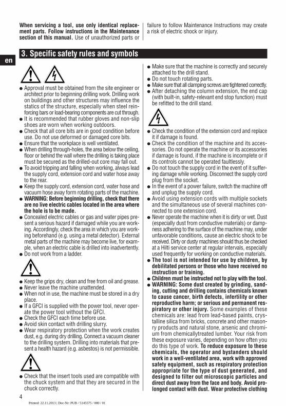
to improve blood circulation in your fingers.● The user and any other persons in the vicinity must
wear suitable eye protection, a hard hat, ear protec-tion, protective gloves and safety footwear while themachine is in use.
Wear a hardhat
Wear earprotection
Wear protec-tive gloves
Wear safetyboots
Wear eyeprotection
4. Functional description
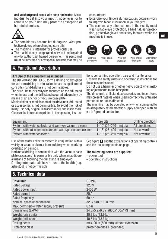
4.1 Use of the equipment as intendedThe DD 200 and DD HD-30 form a drilling rig designedfor wet core drilling in mineral materials using diamondcore bits (hand-held use is not permissible).The drive unit must always be mounted on the drill standwhen in use and the drill stand secured adequately bymeans of an anchor or vacuum base plate.Manipulation or modification of the drive unit, drill standor accessories is not permissible. To avoid the risk ofinjury, use only original Hilti accessories and insert tools.Observe the information printed in the operating instruc-
tions concerning operation, care and maintenance.Observe the safety rules and operating instructions forthe accessories used.Do not use a hammer or other heavy object when mak-ing adjustments to the baseplate.The drive unit, drill stand, accessories and insert toolsmay present hazards when used incorrectly by untrainedpersonnel or not as directed.The machine may be operated only when connected toan adequately rated electric supply equipped with anearth / ground conductor.
Equipment Core bits Drilling directionSystem with water collector and wet-type vacuum cleaner 1–10" (25–250 mm) dia. All directionsSystem without water collector and wet-type vacuum cleaner 1–16" (25–400 mm) dia. Not upwardsSystem with water collector 1–10" (25–250 mm) dia. Not upwards
Use of the water collector system in conjunction with awet-type vacuum cleaner is mandatory when workingoverhead on ceilings.Horizontal drilling in conjunction with the vacuum baseplate (accessory) is permissible only when an addition-al means of securing the drill stand is employed.Drilling into materials hazardous to the health (e.g.asbestos) is not permissible.
See figure � and the explanations of operating controlsand the tool components on page 1.
The following items are supplied: – power tool– operating instructions
5. Technical dataDrive unit DD 200Rated voltage 120 VRated power input 2400 WRated current 20 ARated frequency 60 HzNominal speed under no load 320 / 640 / 1300 /minMax. permissible water supply pressure 6 barDimensions (LxWxH) 24.8×5.9×6.8 in (630×150×173 mm)Weight (drive unit) 30.6 lbs (13.9 kg)Weight (drill stand) 40.3 lbs (18.3 kg)Drilling depth max. 20 in (500 mm) without extensionProtection class protection class I (grounded)
Printed: 22.11.2013 | Doc-Nr: PUB / 5145575 / 000 / 01
6
en
6. Before use
-NOTE-The mains voltage must correspond with the informa-tion printed on the type plate. Ensure that the machineis disconnected from the electric supply.
6.1 Use of extension cordsUse only extension cords of a type approved for theapplication and with conductors of adequate cross sec-tion. Recommended minimum conductor cross sectionand max. cable lengthsMains voltage Conductor cross section
mm2 AWGConductor cross section 1.5 2.0 2,.5 3.5 14 12100 V not per- not per- not per- 25 m not per- –
missible missible missible missible110–120 V not per- not per- 20 m – not per-
missible missible missible 75 ft220–240 V 30 m – 50 m – – –
Do not use extension cords with 1.25 mm2 or 16 AWGconductor cross sections.
6.2 Use of a generator or transformer This machine may be powered by a generator or trans-former which fulfils the following conditions:– AC voltage, output power at least 4000 VA– The operating voltage must be within +5% and –15%
of the rated voltage at all times.– Frequency range 50 – 60 Hz, never above 65Hz– Automatic voltage regulation with starting boostNever operate other machines or appliances from thegenerator or transformer at the same time. Switchingother machines or appliances on and off may causeundervoltage and / or overvoltage peaks, resulting indamage to the machine.
6.3 Preparations
-CAUTION-
● The machine, the diamond core bitand the drill stand are heavy.
● There is a risk of pinching parts ofthe body.
● Wear a hard hat, protective glovesand safety boots.
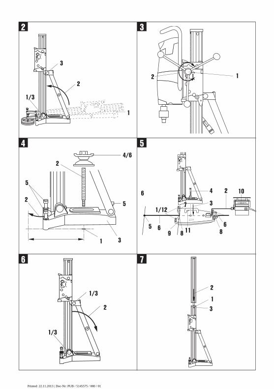
2. Pivot the column into the vertical position (as far asit will go).
3. Tighten the screw at the top end of the strut and atthe column pivot securely.
-NOTE-The end cap must be fitted on the end of the column. Itserves as a protector and as the end stop.
6.3.2 Fitting the hand wheel �-NOTE-The hand wheel can be fitted on the left or right side ofthe carriage, on either of the two axles. The upper axledrives the carriage directly while the lower axle drivesthe carriage by way of reduction gearing.1. Fit the hand wheel to one of the two axles on either
the left or right side of the carriage.2. Secure the hand wheel with the screw provided.
6.3.3 Fastening the drill stand with an anchor �-WARNING-Use an anchor suitable for the material on which youare working and observe the anchor manufacturer'sinstructions.
-NOTE-Hilti M16 metal expansion anchors are usually suitablefor fastening diamond core drilling equipment to uncrackedconcrete. Under certain conditions it may be necessaryto use an alternative fastening method. Please contactHilti Technical Service if you have any questions aboutsecure fastening.
1. Set the anchor, of a type suitable for the material onwhich you are working, ideally at a distance of 330mm (13") from the center of the point where the holeis to be drilled.
2. Screw the clamping spindle (accessory) into the anchor.3. Position the drill stand over the spindle and bring it
into alignment with the aid of the hole center indica-tor. When the spacer is used (accessory), the holecenter indicator cannot be used to align the drill stand.
4. Screw the clamping nut onto the spindle but do nottighten it.
5. Level the base plate by way of the three leveling screws.The two level indicators on the carriage serve as a lev-eling aid.
6. Use a 27 mm AF open-end wrench to tighten theclamping nut on the spindle. Alternatively, the rearleveling screws can be tightened. The strut can bepivoted out of the way to facilitate access.
7. Check that the drill stand is fastened securely.6.3.1 Setting up the drill stand �
-NOTE-If the drill stand has been folded up to facilitate trans-port, proceed as follows:1. Release the screws at the top end of the strut and at
the column pivot.
Printed: 22.11.2013 | Doc-Nr: PUB / 5145575 / 000 / 01
7
en
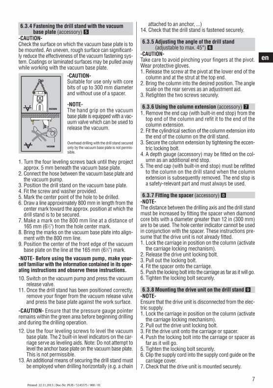
6.3.4 Fastening the drill stand with the vacuumbase plate (accessory) �
-CAUTION-Check the surface on which the vacuum base plate is tobe mounted. An uneven, rough surface can significant-ly reduce the effectiveness of the vacuum fastening sys-tem. Coatings or laminated surfaces may be pulled awaywhile working with the vacuum base plate.
-CAUTION-Suitable for use only with corebits of up to 300 mm diameterand without use of a spacer.
-NOTE-The hand grip on the vacuumbase plate is equipped with a vac-uum valve which can be used torelease the vacuum.
1. Turn the four leveling screws back until they projectapprox. 5 mm beneath the vacuum base plate.
2. Connect the hose between the vacuum base plate andthe vacuum pump.
3. Position the drill stand on the vacuum base plate.4. Fit the screw and washer provided.5. Mark the center point of the hole to be drilled.6. Draw a line approximately 800 mm in length from the
center mark toward the approx. position at which thedrill stand is to be secured.
7. Make a mark on the 800 mm line at a distance of 165 mm (61⁄2") from the hole center mark.
8. Bring the marks on the vacuum base plate into align-ment with the 800 mm line.
9. Position the center of the front edge of the vacuumbase plate on the line at the 165 mm (61⁄2") mark.
-NOTE- Before using the vacuum pump, make your-self familiar with the information contained in its oper-ating instructions and observe these instructions.10. Switch on the vacuum pump and press the vacuum
release valve.11. Once the drill stand has been positioned correctly,
remove your finger from the vacuum release valveand press the base plate against the work surface.
-CAUTION- Ensure that the pressure gauge pointerremains within the green area before beginning drillingand during the drilling operation.12. Use the four leveling screws to level the vacuum
base plate. The 2 built-in level indicators on the car-riage serve as leveling aids. Note: Do not attempt tolevel the anchor base plate on the vacuum base plate.This is not permissible.
13. An additional means of securing the drill stand mustbe employed when drilling horizontally (e.g. a chain
attached to an anchor, ...)14. Check that the drill stand is fastened securely.
6.3.5 Adjusting the angle of the drill stand (adjustable to max. 45°) �
-CAUTION-Take care to avoid pinching your fingers at the pivot.Wear protective gloves.1. Release the screw at the pivot at the lower end of the
column and at the strut at the top end.2. Bring the column into the desired position. The angle
scale on the rear serves as an adjustment aid.3. Retighten the two screws securely.
6.3.6 Using the column extension (accessory) �1. Remove the end cap (with built-in end stop) from the
top end of the column and refit it to the end of the column extension.
2. Fit the cylindrical section of the column extension intothe end of the column on the drill stand.
3. Secure the column extension by tightening the eccen-tric locking bolt.
4. A depth gauge (accessory) may be fitted on the col-umn as an additional end stop.
5. The end cap (with built-in end stop) must be refittedto the column on the drill stand when the columnextension is subsequently removed. The end stop isa safety-relevant part and must always be used.
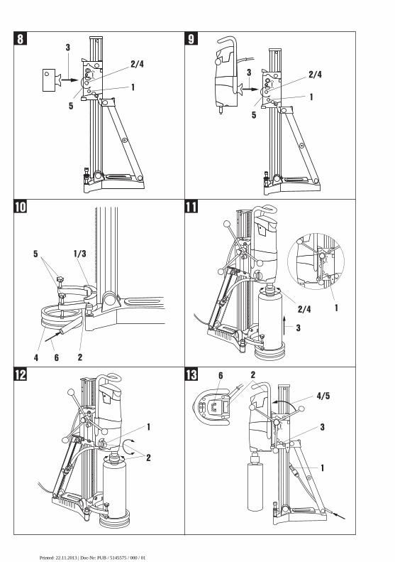
6.3.7 Fitting the spacer (accessory) -NOTE-The distance between the drilling axis and the drill standmust be increased by fitting the spacer when diamondcore bits with a diameter greater than 12 in (300 mm)are to be used. The hole center indicator cannot be usedin conjunction with the spacer. These instructions pre-sume that the drive unit is not already fitted.1. Lock the carriage in position on the column (activate
the carriage locking mechanism).2. Release the drive unit locking bolt.3. Pull out the locking bolt.4. Fit the spacer onto the carriage.5. Push the locking bolt into the carriage as far as it will go.6. Tighten the locking bolt securely.
6.3.8 Mounting the drive unit on the drill stand -NOTE-Ensure that the drive unit is disconnected from the elec-tric supply.1. Lock the carriage in position on the column (activate
the carriage locking mechanism).2. Pull out the drive unit locking bolt.3. Fit the drive unit onto the carriage or spacer.4. Push the locking bolt into the carriage or spacer as
far as it will go.5. Tighten the locking bolt securely.6. Clip the supply cord into the supply cord guide on the
carriage cover.7. Check that the drive unit is mounted securely.
Overhead drilling with the drill stand securedonly by the vacuum base plate is not permis-sible.
VACUUM
VACUUM
Printed: 22.11.2013 | Doc-Nr: PUB / 5145575 / 000 / 01
8
en
6.3.9 Connecting the water supply 1. Close the water flow regulator on the drive unit.2. Connect the water supply hose to the hose connector.
-NOTE-A water flow indicator (accessory) can be connectedbetween the water supply hose and the hose connectoron the drive unit.
-CAUTION-Check the hoses for damage at regular intervals andensure that the maximum permissible water supply pres-sure of 6 bar is not exceeded.
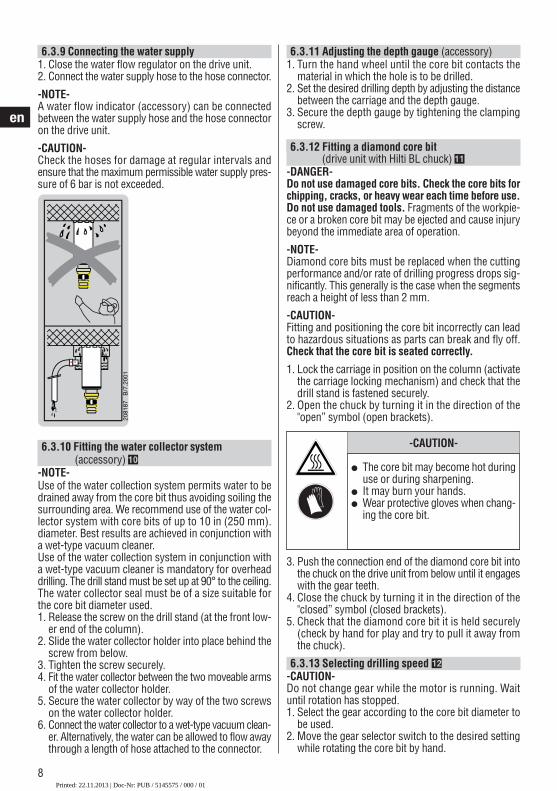
6.3.10 Fitting the water collector system(accessory) ��
-NOTE-Use of the water collection system permits water to bedrained away from the core bit thus avoiding soiling thesurrounding area. We recommend use of the water col-lector system with core bits of up to 10 in (250 mm).diameter. Best results are achieved in conjunction witha wet-type vacuum cleaner.Use of the water collection system in conjunction witha wet-type vacuum cleaner is mandatory for overheaddrilling. The drill stand must be set up at 90° to the ceiling.The water collector seal must be of a size suitable forthe core bit diameter used.1. Release the screw on the drill stand (at the front low-
er end of the column).2. Slide the water collector holder into place behind the
screw from below.3. Tighten the screw securely.4. Fit the water collector between the two moveable arms
of the water collector holder.5. Secure the water collector by way of the two screws
on the water collector holder.6. Connect the water collector to a wet-type vacuum clean-
er. Alternatively, the water can be allowed to flow awaythrough a length of hose attached to the connector.
6.3.11 Adjusting the depth gauge (accessory)1. Turn the hand wheel until the core bit contacts the
material in which the hole is to be drilled.2. Set the desired drilling depth by adjusting the distance
between the carriage and the depth gauge.3. Secure the depth gauge by tightening the clamping
screw.
6.3.12 Fitting a diamond core bit (drive unit with Hilti BL chuck) ��
-DANGER-Do not use damaged core bits. Check the core bits forchipping, cracks, or heavy wear each time before use.Do not use damaged tools. Fragments of the workpie-ce or a broken core bit may be ejected and cause injurybeyond the immediate area of operation.
-NOTE-Diamond core bits must be replaced when the cuttingperformance and/or rate of drilling progress drops sig-nificantly. This generally is the case when the segmentsreach a height of less than 2 mm.
-CAUTION-Fitting and positioning the core bit incorrectly can leadto hazardous situations as parts can break and fly off.Check that the core bit is seated correctly.
1. Lock the carriage in position on the column (activatethe carriage locking mechanism) and check that thedrill stand is fastened securely.
2. Open the chuck by turning it in the direction of the"open” symbol (open brackets).
3. Push the connection end of the diamond core bit intothe chuck on the drive unit from below until it engageswith the gear teeth.
4. Close the chuck by turning it in the direction of the"closed” symbol (closed brackets).
5. Check that the diamond core bit it is held securely(check by hand for play and try to pull it away fromthe chuck).
6.3.13 Selecting drilling speed �-CAUTION-Do not change gear while the motor is running. Waituntil rotation has stopped.1. Select the gear according to the core bit diameter to
be used.2. Move the gear selector switch to the desired setting
while rotating the core bit by hand.
-CAUTION-
● The core bit may become hot duringuse or during sharpening.
● It may burn your hands.● Wear protective gloves when chang-
ing the core bit.
Printed: 22.11.2013 | Doc-Nr: PUB / 5145575 / 000 / 01
9
en
7. Operation
7.1 Switching on and checking the GFCI groundfault interrupter
1. Plug the drive unit supply cord into an electric sock-et with earth connection.
2. Press the "ON" button on the GFCI ground fault inter-rupter (the indicator must light).
3. Press the "TEST" button on the GFCI ground fault inter-rupter (the indicator must go out).
-DANGER-If the indicator continues to light, further operation ofthe machine ist not permissible. Have the machine repair -ed by a qualified specialist using genuine Hilti spare parts.
4. Press the "ON" button on the GFCI ground fault inter-rupter (the indicator must light).
7.2 Core bit diameters and corresponding gears
Gear Core bit diameter
1 152–400 mm (6" – 16")2 82–162 mm (31/4" – 63/8")3 25– 82 mm (1" – 31/4")
When coring heavily reinforced or very hard concre-te (e.g. flint or high-performance concrete), particu-larly with diameters 82 mm (31/4") and 152–162 mm(6"–63/8"), it is recommended to use the lower gear.
7.3 Operating the drilling machine without the watercollector system and wet vacuum cleaner
-NOTE-The water flows away in uncontrolled fashion. Overheaddrilling is not permissible!
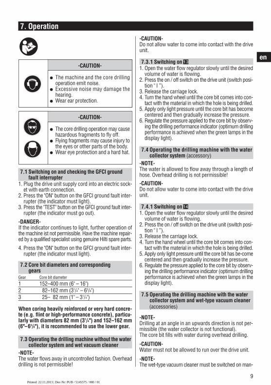
-CAUTION-
● The machine and the core drillingoperation emit noise.
● Excessive noise may damage thehearing.
● Wear ear protection.
-CAUTION-
● The core drilling operation may causehazardous fragments to fly off.
● Flying fragments may cause injury tothe eyes or other parts of the body.
● Wear eye protection and a hard hat.
-CAUTION-Do not allow water to come into contact with the driveunit.
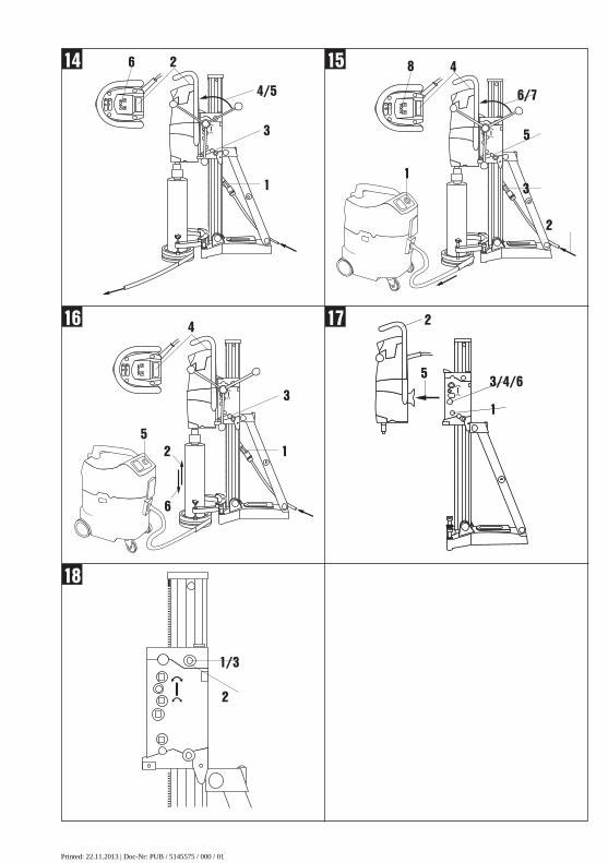
7.3.1 Switching on ��1. Open the water flow regulator slowly until the desired
volume of water is flowing.2. Press the on / off switch on the drive unit (switch posi-
tion " I ”).3. Release the carriage lock.4. Turn the hand wheel until the core bit comes into con-
tact with the material in which the hole is being drilled.5. Apply only light pressure until the core bit has become
centered and then gradually increase the pressure.6. Regulate the pressure applied to the core bit by observ-
ing the drilling performance indicator (optimum drillingperformance is achieved when the green lamps in thedisplay light).
7.4 Operating the drilling machine with the watercollector system (accessory)
-NOTE-The water is allowed to flow away through a length ofhose. Overhead drilling is not permissible!-CAUTION-Do not allow water to come into contact with the driveunit.
7.4.1 Switching on ��1. Open the water flow regulator slowly until the desired
volume of water is flowing.2. Press the on / off switch on the drive unit (switch posi-
tion " I ”).3. Release the carriage lock.4. Turn the hand wheel until the core bit comes into con-
tact with the material in which the hole is being drilled.5. Apply only light pressure until the core bit has be-come
centered and then gradually increase the pressure.6. Regulate the pressure applied to the core bit by observ-
ing the drilling performance indicator (optimum drillingperformance is achieved when the green lamps in thedisplay light).
7.5 Operating the drilling machine with the watercollector system and wet-type vacuum cleaner (accessories)
-NOTE-Drilling at an angle in an upwards direction is not per-missible (the water collector is not functional).The core bit fills with water during overhead drilling.
-CAUTION-Water must not be allowed to run over the drive unit.
-NOTE-The wet-type vacuum cleaner must be switched on man-
Printed: 22.11.2013 | Doc-Nr: PUB / 5145575 / 000 / 01
10
en
ually before beginning drilling and switched off manu-ally at the end of the drilling operation.
7.5.1 Switching on ��1. Switch on the wet-type vacuum cleaner. Do not use
automatic mode.2. Ensure that the water supply is connected and ready
for use.3. Open the water flow regulator.4. Press the on / off switch on the drive unit (switch posi-
tion “I”).5. Release the carriage lock.6. Turn the hand wheel until the core bit comes into con-
tact with the material in which the hole is being drilled.7. Apply only light pressure until the core bit has become
centered and then gradually increase the pressure.8. Regulate the pressure applied to the core bit by observ-
ing the drilling performance indicator (optimum drillingperformance is achieved when the green lamps in thedisplay light).
7.6 Switching off ��1. Close the water flow regulator.2. Withdraw the diamond core bit from the hole.
Caution: The core bit fills with water during overheaddrilling. After overhead drilling, the water must firstbe allowed to drain from the core bit. This is done bydisconnecting the water supply hose from the con-nector on the drive unit and then opening the waterflow regulator valve (do not allow the water to flowback through the water flow indicator). The watermust not be allowed to run over the drive unit.
3. Engage the carriage lock.4. Switch off the drive unit.5. Switch off the vacuum cleaner, if used.6. To ensure that the drill stand remains in balance, low-
er the core bit until in contact with the working sur-face or fold out the hole center indicator (this is noteffective if using the vacuum baseplate).
7. If necessary, remove the core from the core bit.
7.7 Removing the drive unit from the drill stand ��-NOTE-Ensure that the machine is disconnected from the mainssupply.1. Secure the carriage on the column by engaging the
carriage lock.2. Hold the drive unit securely with one hand on the car-
rying grip. -CAUTION- The drive unit may otherwisefall from the drill stand!
3. Release the drive unit eccentric locking bolt with theother hand.
4. Pull out the eccentric locking bolt.5. Remove the drive unit from the carriage.6. Push the eccentric locking bolt back into the carriage
as far as it will go.
7.8 Disposing of drilling slurrysee Section 11 “Disposal”.
7.9 Procedure in the event of the core bit stickingeThe slip clutch will be activated if the core bit sticks. Thepower tool must then be switched off by the operator.To release the core bit, proceed as follows:
Using an open-end wrench to release the core bit1. Disconnect the supply cord plug from the power out-
let.2. Grip the core bit close to the connection end with a
suitable open-end wrench and rotate the core bit torelease it.
3. Plug the supply cord back into the power outlet.
Using the spider wheel to release the core bit1. Disconnect the supply cord plug from the power out-
let.2. Release the core bit by rotating it with the spider wheel.3. Plug the supply cord back into the power outlet.4. Continue the drilling operation.
7.10 Transport and storage
-NOTE-– Transport the drive unit, drill stand and diamond core
bit as separate units.– Use the wheel assembly (accessory) to facilitate trans-
port.– Open the water flow regulator before storing the power
tool. Especially at temperatures below freezing, takecare to ensure that no water remains in the power tool
Printed: 22.11.2013 | Doc-Nr: PUB / 5145575 / 000 / 01
11
en
8. Care and maintenanceDisconnect the supply cord plug from the socket.
Care of insert tools and metal partsRemove any dirt adhering to the core bits and protecttheir surfaces from corrosion by rubbing them with anoily cloth from time to time.
8.1 Care of the machine-CAUTION-Keep the power tool, especially its grip surfaces, cleanand free from oil and grease. Do not use cleaning agentswhich contain silicone.The outer casing of the tool is made from impactresis-tant plastic. Sections of the grip are made from a syn-thetic rubber material. Never operate the tool when the ventilation slots areblocked. Clean the ventilation slots carefully using a drybrush. Do not permit foreign objects to enter the interi-or of the tool. Clean the outside of the tool at regular intervals with aslightly damp cloth. Do not use a spray, steam pressurecleaning equipment or running water for cleaning. Thismay negatively affect the electrical safety of the tool.
8.2 MaintenanceCheck all external parts of the machine for damage atregular intervals and check that all controls operatefaultlessly. Do not operate the machine if parts are dam-aged or when the controls do not function faultlessly.If necessary, the machine should be repaired at a Hiltirepair center.Repairs to the electrical section of the machine maybe carried out only by trained electrical specialists.
8.3 Replacing the carbon brushesThe indicator lamp with the wrench symbol lights whenthe carbon brushes require to be replaced.
Failure to observe the following instructions may pre-sent a possibility of coming into contact with a dan-gerous high voltage. The machine may be operated,serviced and repaired only by authorized, trained per-sonnel. This personnel must be informed of any spe-cial hazards that may be encountered.1. Disconnect the drive unit from the electric supply.2. Remove the covers from the right and left sides of
the drive unit.3. Remove the used carbon brushes from the drive
unit. Note how the brushes are fitted.4. Fit the new carbon brushes exactly as the old car-
bon brushes (Spare part no.: 279526).5. Screw the covers back on to the right and left sides
of the machine.
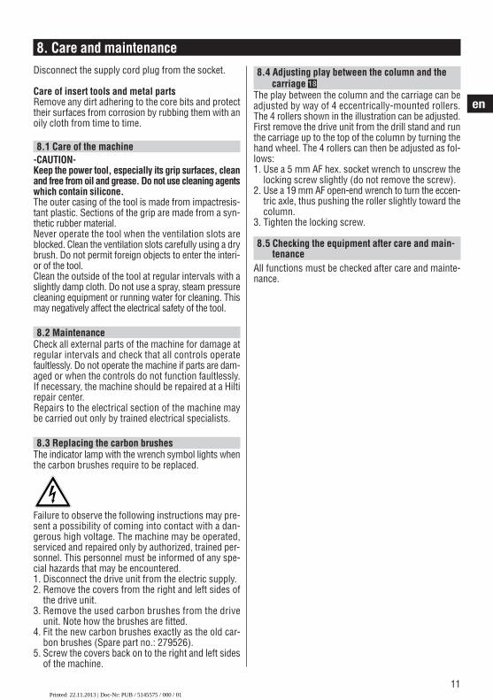
8.4 Adjusting play between the column and the carriage ��
The play between the column and the carriage can beadjusted by way of 4 eccentrically-mounted rollers.The 4 rollers shown in the illustration can be adjusted.First remove the drive unit from the drill stand and runthe carriage up to the top of the column by turning thehand wheel. The 4 rollers can then be adjusted as fol-lows:1. Use a 5 mm AF hex. socket wrench to unscrew the
locking screw slightly (do not remove the screw).2. Use a 19 mm AF open-end wrench to turn the eccen-
tric axle, thus pushing the roller slightly toward thecolumn.
3. Tighten the locking screw.
8.5 Checking the equipment after care and main-tenance
All functions must be checked after care and mainte-nance.
Printed: 22.11.2013 | Doc-Nr: PUB / 5145575 / 000 / 01
12
en
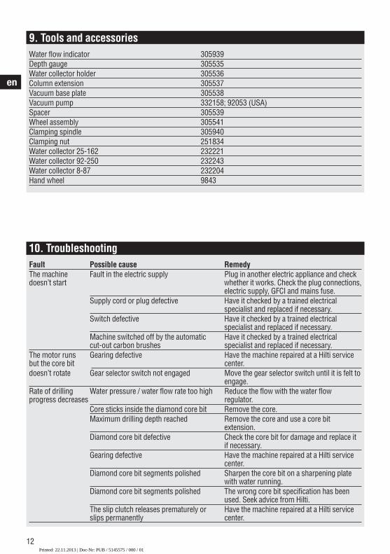
10. TroubleshootingFault Possible cause RemedyThe machine Fault in the electric supply Plug in another electric appliance and check doesn’t start whether it works. Check the plug connections,
electric supply, GFCI and mains fuse.Supply cord or plug defective Have it checked by a trained electrical
specialist and replaced if necessary.Switch defective Have it checked by a trained electrical
specialist and replaced if necessary.Machine switched off by the automatic Have it checked by a trained electricalcut-out carbon brushes specialist and replaced if necessary.
The motor runs Gearing defective Have the machine repaired at a Hilti service but the core bit center.doesn’t rotate Gear selector switch not engaged Move the gear selector switch until it is felt to
engage. Rate of drilling Water pressure / water flow rate too high Reduce the flow with the water flowprogress decreases regulator.
Core sticks inside the diamond core bit Remove the core.Maximum drilling depth reached Remove the core and use a core bit
extension.Diamond core bit defective Check the core bit for damage and replace it
if necessary.Gearing defective Have the machine repaired at a Hilti service
center.Diamond core bit segments polished Sharpen the core bit on a sharpening plate
with water running.Diamond core bit segments polished The wrong core bit specification has been
used. Seek advice from Hilti.The slip clutch releases prematurely or Have the machine repaired at a Hilti service slips permanently center.
9. Tools and accessoriesWater flow indicator 305939Depth gauge 305535Water collector holder 305536Column extension 305537Vacuum base plate 305538 Vacuum pump 332158; 92053 (USA) Spacer 305539Wheel assembly 305541Clamping spindle 305940Clamping nut 251834Water collector 25-162 232221Water collector 92-250 232243Water collector 8-87 232204Hand wheel 9843
Printed: 22.11.2013 | Doc-Nr: PUB / 5145575 / 000 / 01

13
en
The motor cuts out The machine stops running Reduce the pressure applied.Electronics defective Have the machine repaired at a Hilti service
center.Electric power failure Check the plug connections, electric supply,
GFCI and mains fuse.Cooling fan defective Have the machine repaired at a Hilti service
center.Carbon brushes worn Have the machine repaired at a Hilti service
center.Water leakage at Shaft seal defective Have the machine repaired at a Hilti service the water swivel or center. gear housing Water pressure too high Reduce the water pressure.The diamond core Chuck or connection end dirty or damaged Clean the connection end / chuck or replace if bit cannot be fitted necessary.into the chuck Water leakage at Chuck or connection end dirty Clean the connection end / chuck.nthe chuck duringoperation Core bit not screwed securely into the Tighten it securely.
chuckChuck seal or core bit connection end Check the seal and replace it if necessary.defective
Excessive play in Screw at the top end of the strut and / or Tighten the screws.the drilling system at the column pivot point is loose
Core bit not screwed securely into the Tighten it securely.chuckDrive unit locking mechanism loose Tighten the drive unit locking mechanism.Leveling screws or clamping spindle Retighten the leveling screws clampingnot tightened spindle. Excessive play at the carriage Adjust the play at the carriage guide rollers.Excessive play at the chuck Check that the chuck runs true and replace it
if necessary.Connection end defective Check the connection end and replace it if
necessary.
Printed: 22.11.2013 | Doc-Nr: PUB / 5145575 / 000 / 01
14
en
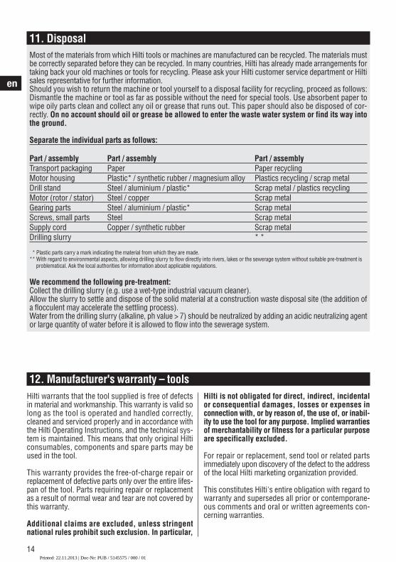
11. DisposalMost of the materials from which Hilti tools or machines are manufactured can be recycled. The materials mustbe correctly separated before they can be recycled. In many countries, Hilti has already made arrangements fortaking back your old machines or tools for recycling. Please ask your Hilti customer service department or Hiltisales representative for further information.Should you wish to return the machine or tool yourself to a disposal facility for recycling, proceed as follows:Dismantle the machine or tool as far as possible without the need for special tools. Use absorbent paper towipe oily parts clean and collect any oil or grease that runs out. This paper should also be disposed of cor-rectly. On no account should oil or grease be allowed to enter the waste water system or find its way intothe ground.
Separate the individual parts as follows:
Part / assembly Part / assembly Part / assemblyTransport packaging Paper Paper recyclingMotor housing Plastic* / synthetic rubber / magnesium alloy Plastics recycling / scrap metalDrill stand Steel / aluminium / plastic* Scrap metal / plastics recyclingMotor (rotor / stator) Steel / copper Scrap metalGearing parts Steel / aluminium / plastic* Scrap metalScrews, small parts Steel Scrap metalSupply cord Copper / synthetic rubber Scrap metalDrilling slurry * *
** Plastic parts carry a mark indicating the material from which they are made.** With regard to environmental aspects, allowing drilling slurry to flow directly into rivers, lakes or the sewerage system without suitable pre-treatment is
problematical. Ask the local authorities for information about applicable regulations.
We recommend the following pre-treatment:Collect the drilling slurry (e.g. use a wet-type industrial vacuum cleaner).Allow the slurry to settle and dispose of the solid material at a construction waste disposal site (the addition ofa flocculent may accelerate the settling process).Water from the drilling slurry (alkaline, ph value > 7) should be neutralized by adding an acidic neutralizing agentor large quantity of water before it is allowed to flow into the sewerage system.
12. Manufacturer's warranty – toolsHilti warrants that the tool supplied is free of defectsin material and workmanship. This warranty is valid solong as the tool is operated and handled correctly,cleaned and serviced properly and in accordance withthe Hilti Operating Instructions, and the technical sys-tem is maintained. This means that only original Hilticonsumables, components and spare parts may beused in the tool.
This warranty provides the free-of-charge repair orreplacement of defective parts only over the entire lifes-pan of the tool. Parts requiring repair or replacementas a result of normal wear and tear are not covered bythis warranty.
Additional claims are excluded, unless stringentnational rules prohibit such exclusion. In particular,
Hilti is not obligated for direct, indirect, incidentalor consequential damages, losses or expenses inconnection with, or by reason of, the use of, or inabil-ity to use the tool for any purpose. Implied warrantiesof merchantability or fitness for a particular purposeare specifically excluded.
For repair or replacement, send tool or related partsimmediately upon discovery of the defect to the addressof the local Hilti marketing organization provided.
This constitutes Hilti's entire obligation with regard towarranty and supersedes all prior or contemporane-ous comments and oral or written agreements con-cerning warranties.
Printed: 22.11.2013 | Doc-Nr: PUB / 5145575 / 000 / 01

*305561*
3055
61
Hilti CorporationLI-9494 SchaanTel.: +423 / 234 21 11Fax:+423 / 234 29 65www.hilti.com
Hilti = registered trademark of Hilti Corp., Schaan W 2936 | 1013 | 2-Pos. 3 | 1 Printed in Germany © 2013Right of technical and programme changes reserved S. E. & O. 305561 / A4
Printed: 22.11.2013 | Doc-Nr: PUB / 5145575 / 000 / 01