operating instructions for model 3190 series analytical instruments i operating instructions for...
TRANSCRIPT

iTeledyne Analytical Instruments
OPERATING INSTRUCTIONS
FOR
Model 3190 Series
Trace Oxygen Analyzer
P/N M6464106/21/2000
ECO # 00-0221
HIGHLY TOXIC AND OR FLAMMABLE LIQUIDS OR GASES MAY BE PRESENT IN THIS MONITORING SYSTEM.
PERSONAL PROTECTIVE EQUIPMENT MAY BE REQUIRED WHEN SERVICING THIS SYSTEM.
HAZARDOUS VOLTAGES EXIST ON CERTAIN COMPONENTS INTERNALLY WHICH MAY PERSIST FOR ATIME EVEN AFTER THE POWER IS TURNED OFF AND DISCONNECTED.
ONLY AUTHORIZED PERSONNEL SHOULD CONDUCT MAINTENANCE AND/OR SERVICING. BEFORECONDUCTING ANY MAINTENANCE OR SERVICING CONSULT WITH AUTHORIZED SUPERVISOR/MANAGER.
DANGER

ii Teledyne Analytical Instruments
Copyright © 1999 Teledyne Analytical Instruments
All Rights Reserved. No part of this manual may be reproduced, transmitted,transcribed, stored in a retrieval system, or translated into any other language or computerlanguage in whole or in part, in any form or by any means, whether it be electronic,mechanical, magnetic, optical, manual, or otherwise, without the prior written consent ofTeledyne Analytical Instruments, 16830 Chestnut Street, City of Industry, CA 91749-1580.
Warranty
This equipment is sold subject to the mutual agreement that it is warranted by usfree from defects of material and of construction, and that our liability shall be limited toreplacing or repairing at our factory (without charge, except for transportation), or atcustomer plant at our option, any material or construction in which defects becomeapparent within one year from the date of shipment, except in cases where quotations oracknowledgements provide for a shorter period. Components manufactured by others bearthe warranty of their manufacturer. This warranty does not cover defects caused by wear,accident, misuse, neglect or repairs other than those performed by Teledyne or an autho-rized service center. We assume no liability for direct or indirect damages of any kind andthe purchaser by the acceptance of the equipment will assume all liability for any damagewhich may result from its use or misuse.
We reserve the right to employ any suitable material in the manufacture of ourapparatus, and to make any alterations in the dimensions, shape or weight of any parts, inso far as such alterations do not adversely affect our warranty.
Important Notice
This instrument provides measurement readings to its user, and serves as a tool bywhich valuable data can be gathered. The information provided by the instrument mayassist the user in eliminating potential hazards caused by his process; however, it isessential that all personnel involved in the use of the instrument or its interface, with theprocess being measured, be properly trained in the process itself, as well as all instrumen-tation related to it.
The safety of personnel is ultimately the responsibility of those who control processconditions. While this instrument may be able to provide early warning of imminentdanger, it has no control over process conditions, and it can be misused. In particular, anyalarm or control systems installed must be tested and understood, both as to how theyoperate and as to how they can be defeated. Any safeguards required such as locks, labels,or redundancy, must be provided by the user or specifically requested of Teledyne at thetime the order is placed.
Therefore, the purchaser must be aware of the hazardous process conditions. Thepurchaser is responsible for the training of personnel, for providing hazard warningmethods and instrumentation per the appropriate standards, and for ensuring that hazardwarning devices and instrumentation are maintained and operated properly.
Teledyne Analytical Instruments (TAI), the manufacturer of this instrument,cannot accept responsibility for conditions beyond its knowledge and control. Nostatement expressed or implied by this document or any information disseminated by themanufacturer or its agents, is to be construed as a warranty of adequate safety controlunder the user’s process conditions.

iiiTeledyne Analytical Instruments
Specific Model Information
The instrument for which this manual was supplied may incorporate one ormore options not supplied in the standard instrument. Commonly availableoptions are listed below, with check boxes. Any that are incorporated in theinstrument for which this manual is supplied are indicated by a check mark in thebox.
Instrument Serial Number: _______________________
Options Included in the Instrument with the Above Serial Number:
❑❑❑❑❑ Class A-2C Micro-Fuel Cell: For 0-100% CO2 background and General
Purpose (range 0-10 ppm O2 minimum).
❑❑❑❑❑ Class B-2C Micro-Fuel Cell: For General Purpose and high hydrogenor helium backgrounds (range 0-10 ppmO
2 minimum).
❑❑❑❑❑ Class Z-2C Micro-Fuel Cell: For faster recovery after air calibration
(range 0-200 ppm O2 minimum).
Class B-2C is the standard cell provided.

iv Teledyne Analytical Instruments
Contents
Introduction
1.1 Overview ........................................................................ 1-11.2 Main Features of the Analyzer ....................................... 1-11.3 Front Panel Description .................................................. 1-21.4 Rear Panel Description .................................................. 1-3
Operational Theory
2.1 Introduction .................................................................... 2-12.2 Micro-Fuel Cell Sensor .................................................. 2-1
2.2.1 Principles of Operation .......................................... 2-12.2.2 Anatomy of a Micro-Fuel Cell ................................. 2-22.2.3 Electrochemical Reactions .................................... 2-32.2.4 The Effect of Pressure............................................ 2-42.2.5 Calibration Characteristics ..................................... 2-4
2.3 Electronics ..................................................................... 2-52.3.1 General .................................................................. 2-52.3.2 Signal Processing .................................................. 2-5
Installation
3.1 Unpacking the Analyzer ................................................. 3-13.2 Location and Mounting .................................................. 3-2
3.2.1 Control Unit Installation.......................................... 3-23.2.2 External Probe Installation ..................................... 3-23.2.3 Installing the Micro-Fuel Cell ................................. 3-3
3.3 Electrical Connections ................................................... 3-33.4 Gas Connections ........................................................... 3-73.5 Installation Checklist ...................................................... 3-7
Operation
4.1 Introduction .................................................................... 4-14.2 Using the Function and Data Entry Buttons ................... 4-24.3 Setting the Analysis Ranges .......................................... 4-2
4.3.1 HI Range ............................................................... 4-34.3.2 LO Range .............................................................. 4-34.3.3Settle Mode ............................................................... 4-3

vTeledyne Analytical Instruments
4.4 Setting the Alarm Setpoints............................................ 4-34.4.1 HI Alarm ................................................................. 4-34.4.2 LO Alarm ................................................................ 4-34.4.3 Sensor Fail Alarm .................................................. 4-4
4.5 Selecting a Fixed Range or Autoranging ....................... 4-44.6 Calibration ..................................................................... 4-44.7 Displaying Percent & PPM on the LED Display ............. 4-54.8 "SetL" mode in the LED display ..................................... 4-6
Maintenance
5.1 Replacing the Fuse........................................................ 5-15.1.1 AC Powered Units ................................................. 5-15.1.2 DC Powered Units ................................................. 5-2
5.2 Sensor Installation or Replacement ............................... 5-25.2.1 When to Replace a Sensor .................................... 5-25.2.2 Ordering and Handling of Spare Sensors .............. 5-35.2.3 Removing the Micro-Fuel Cell ............................... 5-35.2.4 Installing a Micro-Fuel Cell .................................... 5-45.2.5 Cell Warranty Conditions ....................................... 5-5
Appendix
A.1 Specifications ................................................................ A-1A.2 Spare Parts List ............................................................. A-2A.3 Drawing List ................................................................... A-3A.4 Miscellaneous ................................................................ A-3A.5 Material Safety Data Sheet ............................................ A-4

vi Teledyne Analytical Instruments

1-1
Trace Oxygen Analyzer Introduction 1
Teledyne Analytical Instruments
Introduction
1.1 Overview
The Teledyne Analytical Instruments (TAI) Model 3190 is a micropro-cessor-based trace oxygen analyzer for real-time measurement of traceamounts of oxygen in inert gases, or in a wide variety of gas mixtures. Itfeatures simple operation, fast response, and a compact, rugged construction.Typical applications of the Model 3190 are monitoring nitrogen generatorsand inert gas blanketing applications.
1.2 Main Features of the Analyzer
The main features of the analyzer include:
• High resolution, accurate readings of oxygen content from0-10 ppm through 0-25 %. Large, bright, light-emitting-diodemeter readout.
• Simple pushbutton controls.
• Nylon cell holder.
• Advanced Micro-Fuel Cell, for trace analysis, has a six (6)months warranty and expected lifetime.
• Unaffected by oxidizable gases.
• Fast response and recovery time.
• Microprocessor based electronics: 8-bit CMOS microprocessorwith on-board RAM and 16 kB ROM.
• Two user selectable ranges (from 0-10 ppm through0-9,999 ppm) allow best match to users process and equipment.
• Air-calibration range for convenient spanning at 20.9 %.
• Operator can select Autoranging, which allows the analyzer toautomatically select the proper preset range for a givenmeasurement, or he can lock the analyzer onto a single range.

1-2
1 Introduction Model 3190
Teledyne Analytical Instruments
• Two concentration alarms with adjustable setpoints.
• Sensor failure alarm.
• RS-232 serial digital port for output of concentration and rangedata to a computer, terminal, or other digital device.
• Three analog outputs: two for measurement (0–10 V dc, andnegative ground 4–20 mA dc) and one for range identification(0-10 V dc).
• Compact and rugged Control Unit with flush-panel case.Designed for indoor use. Front panel NEMA-4 rated.
• External Probe can be located six feet or more away, dependingon the existing electromagnetic noise level.
1.3 Front Panel Description
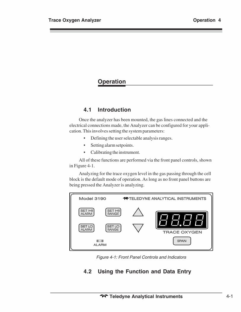
All controls and displays except the power switch are accessible fromthe front panel. See Figure 1-1. The front panel has seven pushbutton mem-brane switches, a digital meter, and an alarm indicator LED for operating theanalyzer. These features are described briefly here and in greater detail inChapter 4, Operation.
Figure 1-1: Front Panel
Function Keys: Seven pushbutton membrane switches are used toselect the function performed by the analyzer:

1-3
Trace Oxygen Analyzer Introduction 1
Teledyne Analytical Instruments
• Set HI Alarm Set the concentration ABOVE which analarm activates.
• Set LO Alarm Set the concentration BELOW which analarm activates.
• Set HI Range Set the high analysis range for the instrument(up to 0-9999 ppm).
• Set LO Range Set the low analysis range for the instrument(down to 0-10 ppm).
• Span Span calibrate the analyzer.
Data Entry Keys: Two pushbutton membrane switches are used tomanually change measurement parameters of the instrument as they aredisplayed on the LED meter readout:
• Up Arrow Increment values of parameters upwards asthey are displayed on the LED readout.
• Down Arrow Increment values of parameters downwards asthey are displayed on the LED readout.
Digital LED Readout: The digital display is a LED device thatproduces large, bright, 7-segment numbers that are legible in any lightingenvironment. It has two functions:
• Meter Readout: As the meter readout, it displays the oxygenconcentration currently being measured.
• Measurement Parameters Readout: It also displays user-definable alarm setpoints, ranges, and span calibration pointwhen they are being checked or changed.
1.4 Rear Panel Description
The rear panel contains the electrical input and output connectors.Separate rear panel illustrations are shown in Figure 1-2 for the AC and DCpowered versions of the instrument. The connectors are described brieflyhere and in detail in the Installation chapter of this manual.

1-4
1 Introduction Model 3190
Teledyne Analytical Instruments
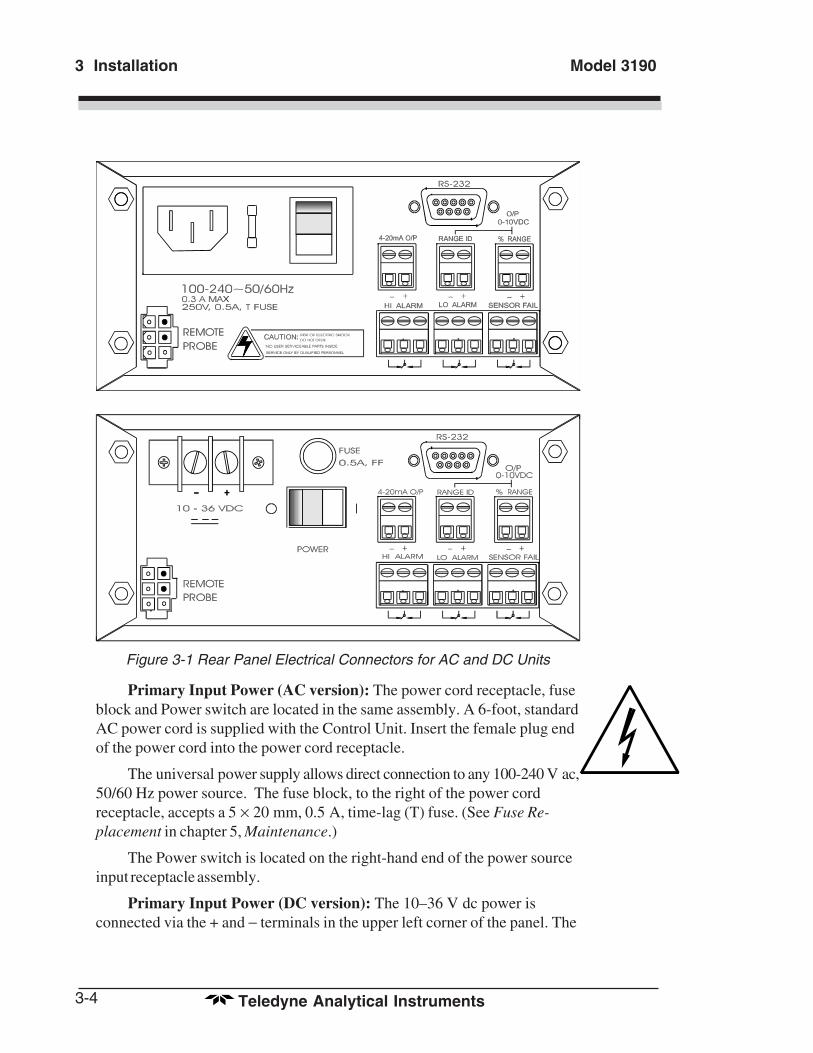
Figure 1-2 Rear Panel (AC and DC versions)
• Power Connection AC version: 100–240 V ac, at 50/60 Hz.The connector housing includes the fuseholder and the power switch.DC version: Requires between 10 and36 V dc.
Fuse Holder: Replacing the fuse isdescribed in Chapter 5, Maintenance.
I/O Power Switch: Turns the instrumentpower ON (1) or OFF (0).
• Analog Outputs 0–10 V dc concentration output.0–10 V dc range ID (or optionaloverrange) output.4–20 mA dc concentration output,negative ground.

1-5
Trace Oxygen Analyzer Introduction 1
Teledyne Analytical Instruments
• Alarm Connections HI Alarm, LO Alarm, and Sensor FailureAlarm connections.
• RS-232 Port Serial digital output of concentration andrange signals.
• External Probe Connects to the Remote Probe or remoteAnalysis Unit.

1-6
1 Introduction Model 3190
Teledyne Analytical Instruments

2-1
Trace Oxygen Analyzer Operational Theory 2
Teledyne Analytical Instruments
Operational Theory
2.1 Introduction
The analyzer is composed of two subsystems:
1. Analysis Unit with Micro-Fuel Cell Sensor
2. Control Unit with Signal Processing, Display and Controls
The Analysis Unit is designed to accept the sample gas and direct it tothe sensitive surface of the Micro-Fuel Cell sensor. The Micro-Fuel Cell isan electrochemical galvanic device that translates the amount of oxygenpresent in the sample into an electrical current.
The Control Unit processes the sensor output and translates it intoelectrical concentration, range, and alarm outputs, and a trace oxygenmeter readout. It contains a microcontroller that manages all signal pro-cessing, input/output, and display functions for the analyzer.
2.2 Micro-Fuel Cell Sensor
2.2.1 Principles of Operation
The oxygen sensor used in the Model 3190 is a Micro-Fuel Celldesigned and manufactured by TAI. It is a sealed, disposable electrochemi-cal transducer.
The active components of the Micro-Fuel Cell are a cathode, ananode, and the 15 % aqueous KOH electrolyte in which they are immersed.The cell converts the energy from a chemical reaction into an electricalcurrent through an external electrical circuit. Its action is similar to that ofa battery.
There is, however, an important difference in the operation of abattery as compared to the Micro-Fuel Cell: In the battery, all reactants are

2-2
2 Operational Theory Model 3190
Teledyne Analytical Instruments
stored within the cell, whereas in the Micro-Fuel Cell, one of the reactants(oxygen) comes from outside the device as a constituent of the sample gasbeing analyzed. The Micro-Fuel Cell is therefore a hybrid between abattery and a true fuel cell. (All of the reactants are stored externally in atrue fuel cell.)
2.2.2 Anatomy of a Micro-Fuel Cell
The Micro-Fuel Cell is a cylinder only 1¼ inches in diameter and 1inch thick. It is made of extremely inert plastic, which can be placedconfidently in practically any environment or sample stream. It is effec-tively sealed, although one end is permeable to oxygen in the sample gas.The other end of the cell is a contact plate consisting of two concentric foilrings. The rings mate with spring-loaded contacts in the sensor blockassembly and provide the electrical connection to the rest of the analyzer.Figure 2-1 illustrates the external features.
Figure 2-1: Micro-Fuel Cell
Refer to Figure 2-2, Cross Section of a Micro-Fuel Cell, which illus-trates the following internal description.
Figure 2-2. Cross Section of a Micro-Fuel Cell (simplified)
2-3
Trace Oxygen Analyzer Operational Theory 2
Teledyne Analytical Instruments
At the top end of the cell is a diffusion membrane of Teflon, whosethickness is very accurately controlled. Beneath the diffusion membranelies the oxygen sensing element—the cathode—with a surface area almost4 cm2. The cathode has many perforations to ensure sufficient wetting ofthe upper surface with electrolyte, and it is plated with an inert metal.
The anode structure is below the cathode. It is made of lead and has aproprietary design which is meant to maximize the amount of metal avail-able for chemical reaction.
At the rear of the cell, just below the anode structure, is a flexiblemembrane designed to accommodate the internal volume changes thatoccur throughout the life of the cell. This flexibility assures that the sens-ing membrane remains in its proper position, keeping the electrical outputconstant.
The entire space between the diffusion membrane, above the cathode,and the flexible rear membrane, beneath the anode, is filled with electro-lyte. Cathode and anode are submerged in this common pool. They eachhave a conductor connecting them to one of the external contact rings onthe contact plate, which is on the bottom of the cell.
2.2.3 Electrochemical Reactions
The sample gas diffuses through the Teflon membrane. Any oxygenin the sample gas is reduced on the surface of the cathode by the followingHALF REACTION:
O2 + 2H2O + 4e––––– → 4OH––––– (cathode)
(Four electrons combine with one oxygen molecule—in the presenceof water from the electrolyte—to produce four hydroxyl ions.)
When the oxygen is reduced at the cathode, lead is simultaneouslyoxidized at the anode by the following HALF REACTION:
2Pb + 4OH––––– → 2Pb+2 + 2H2O + 4e––––– (anode)
(Two electrons are transferred for each atom of lead that is oxidized.TWO ANODE REACTIONS balance one cathode reaction to transfer fourelectrons.)
The electrons released at the surface of the anode flow to the cathodesurface when an external electrical path is provided. The current is propor-tional to the amount of oxygen reaching the cathode. It is measured andused to determine the oxygen concentration in the gas mixture.
The overall reaction for the fuel cell is the SUM of the half reactionsabove, or:

2-4
2 Operational Theory Model 3190
Teledyne Analytical Instruments
2Pb + O2 → 2PbO
(These reactions will hold as long as no gaseous components capableof oxidizing lead—such as iodine, bromine, chlorine and fluorine—arepresent in the sample. The only likely components are the halogens.)
The output of the fuel cell is limited by (1) the amount of oxygen inthe cell at the time and (2) the amount of stored anode material. In theabsence of oxygen, no current is generated.
2.2.4 The Effect of Pressure
In order to state the amount of oxygen present in the sample as aspecific portion of the gas mixture, it is necessary that the sample diffuseinto the cell under constant pressure.
If the total pressure increases, the rate that oxygen reaches the cathodethrough the diffusing membrane will also increase. The electron transfer,and therefore the external current, will increase, even though the oxygenconcentration of the sample has not changed. It is therefore important thatthe sample pressure at the fuel cell (Usually vent pressure) remain rela-tively constant between calibrations.
2.2.5 Calibration Characteristics
Given that the total pressure of the sample gas on the surface of theMicro-Fuel Cell input is constant, a convenient characteristic of the cell isthat the current produced in an external circuit of constant impedance isdirectly proportional to the rate at which oxygen molecules reach thecathode, and this rate is directly proportional to the concentration of oxy-gen in the gaseous mixture. In other words it has a linear characteristiccurve, as shown in Figure 2-2. Measuring circuits do not have to compen-sate for nonlinearities.
Also, since there is zero output in the absence oxygen, the characteris-tic curve has an absolute zero. The cell itself does not need to be zeroed.
As the cell reaches the end of its useful life, the slope seen in Figure2-2 decreases. In the Model 3190, the slope is monitored. If the inverse ofthe slope:
Span Value (ppm) / Cell Output (nA)
is over 4.447 ppm/nA, a sensor failure alarm is triggered, indicating thatthe cell should be replaced.

2-5
Trace Oxygen Analyzer Operational Theory 2
Teledyne Analytical Instruments
Figure 2-2. Characteristic Input/Output Curve for a Micro-Fuel Cell
2.3 Electronics
2.3.1 General
The signal processing uses an Intel microcontroller with on-boardRAM and ROM to control all signal processing, input/output, and displayfunctions for the analyzer. System power is supplied from a universalpower supply module designed to be compatible with most internationalpower sources.
The power supply circuitry is on the Power Supply PCB, which ismounted vertically, just behind the rear panel of the Control Unit.
The signal processing electronics including the temperature compen-sated amplifier, microcontroller, analog to digital, and digital to analogconverters are located on the Main PCB, which is mounted vertically, justbehind the front panel of the Control Unit.
2.3.2 Signal Processing
Figure 2-3 is a block diagram of the signal processing electronicsdescribed below.

2-6
2 Operational Theory Model 3190
Teledyne Analytical Instruments
Figure 2-3: Block Diagram of the Signal Processing Electronics
In the presence of oxygen the cell generates a current. A current tovoltage amplifier (I–E AMPL) converts this current to a voltage.
The second stage amplifier (TEMP COMP) supplies temperaturecompensation for the oxygen sensor output. The temperature compensationamplifier incorporates a thermistor (THERM) that is physically located inthe cell block. The thermistor is a temperature dependent resistance thatchanges the gain of the amplifier in proportion to the temperature changesin the block. This change is inversely proportional to the change in the celloutput due to the temperature changes. As a result there is negligible netchange in the signal due to temperature changes once the sensor comes toequilibrium. See Specifications in the Appendix.
The output from the temperature compensation amplifier is sent to ananalog to digital converter (ADC), and the resulting digital concentrationsignal is sent to the microcontroller.
The digital concentration signal along with input from the front panelbuttons (KEYBOARD) is processed by the microcontroller, and appropri-ate output signals are directed to the display, alarm relays, and RS-232output. The same digital information is also sent to a 12-bit digital toanalog converter (DAC) that produces the 0-10 V dc analog concentrationsignal and the 0-10 V dc analog range ID output. A current to voltageconverter (E–I CONV) produces the 4-20 mA dc concentration signal.

3-1
Trace Oxygen Analyzer Installation 3
Teledyne Analytical Instruments
Installation
Installation of the analyzer includes:
1. Unpacking the system.
2. Mounting the Control Unit, External Sample Block, and Micro-Fuel Cell sensor.
3. Making the electrical connections.
5. Making the gas connections.
6. Testing the installation.
CAUTIONS: Read this chapter in its entirety before installingthe units.The Model 3190 is for or indoor use only.The sample must be free of entrained solids orwater. However, a high humidity sample is ideal,since it will prevent water loss from the cellelectrolyte.The Micro-Fuel Cell sensor electrolyte is caustic.Do not attempt to open it. Leaking or exhaustedcells should be disposed of in accordance withlocal regulations. Refer to the Material Safety DataSheet in the Appendix.Any damage or scarring of the delicate permeablemembrane on the sensing end of the cell willrequire cell replacement. Prevent contact withmembrane by any solid object.
3.1 Unpacking the Analyzer
As soon as you receive the instrument, carefully unpack and inspectControl Unit, External Probe, and any included accessories for damage.Immediately report any damage to the shipping agent. The analyzer is
OvervoltageCategory II

3 Installation Model 3190
3-2 Teledyne Analytical Instruments
shipped with all the materials you need to install and prepare the system foroperation.
CAUTION: Do not disturb the integrity of the cell package untilthe cell is to be used immediately. If the cell packageis punctured prematurely and air is permitted toenter, cell life will be shortened.
3.2 Location and Mounting
3.2.1 Control Unit Installation
The 3190 Control Unit is designed to be panel-mounted in a generalpurpose, indoor area, away from moisture and the elements. The unit shouldbe installed at viewing level in a sheltered area.
CAUTION: For the DC powered version, the control unitchassis must be isolated from the input powerground.
Refer to the Outline Diagram C-64772 for the physical dimensions ofthe analyzer.
3.2.2 External Probe Installation
The External Probe can be installed in the process any reasonabledistance from the Control Unit. The nominal maximum is 6 ft, but the dis-tance can be more, depending on the level of electromagnetic noise in theoperating environment.
The standard Model 3190 includes the External Probe unit depicted inthe Final Assembly, Dwg C-64641, and the Analysis Unit (probe) Outline,Dwg B-59610. Dimensions are also given in Specifications in the Appendix.
For special applications, the type of External Probe unit supplied mayvary depending on the specific process. With these systems, specific installa-tion and interconnect information is given in a separate probe manual or inan addendum to this manual depending on the model External Probe used.The addendum will reference the specific Outline and InterconnectionDrawings in the Drawings section of this manual, and provides any otherappropriate information.

3-3
Trace Oxygen Analyzer Installation 3
Teledyne Analytical Instruments
For special applications the Micro-Fuel Cell may also be of a differenttype than the standard A-2C, B-2C or Z-2C unit. If this is the case, thepertinent cell specifications will be given in the addendum.
3.2.3 Installing the Micro-Fuel Cell / Cell Block Orientation
A Micro-Fuel Cell is included as a separate item. It must be installedprior to instrument use.
Also, once it is expended, or if the instrument has been idle for alengthy period, the Micro-Fuel Cell will need to be replaced.
Important Installation Note!
During the Installation and/or Replacement of the MFC, Membranesurface MUST ALLWAYS FACE DOWNWARD, and the Contact side ofthe Membrane, MUST be placed FIRST into Analysis Unit.
The reason for proper Installation/Replacement is, if any bubble thatdevelops as the electrolyte dries out will be directed by the gravity awayfrom the membrane.
To install or replace the Micro-Fuel Cell, follow the procedures inChapter 5, Maintenance.
3.3 Electrical Connections
Figure 3-1 shows the two alternate Model 3190 rear panels. The firstillustration shows the AC powered version, and the second illustration showsthe DC powered version. The difference between them is the power connec-tions. Both versions have identical connections for the External Probe, thealarms, and for the digital and analog concentration outputs. For detailedpinouts, see the wiring/interconnection drawings in the Drawings section atthe rear of this manual.
3 Installation Model 3190
3-4 Teledyne Analytical Instruments
Figure 3-1 Rear Panel Electrical Connectors for AC and DC Units
Primary Input Power (AC version): The power cord receptacle, fuseblock and Power switch are located in the same assembly. A 6-foot, standardAC power cord is supplied with the Control Unit. Insert the female plug endof the power cord into the power cord receptacle.
The universal power supply allows direct connection to any 100-240 V ac,50/60 Hz power source. The fuse block, to the right of the power cordreceptacle, accepts a 5 × 20 mm, 0.5 A, time-lag (T) fuse. (See Fuse Re-placement in chapter 5, Maintenance.)
The Power switch is located on the right-hand end of the power sourceinput receptacle assembly.
Primary Input Power (DC version): The 10–36 V dc power isconnected via the + and − terminals in the upper left corner of the panel. The

3-5
Trace Oxygen Analyzer Installation 3
Teledyne Analytical Instruments
fuse receptacle, to the right of the power terminal strip, holds a 0.5 A, veryquick acting fuse. (See Fuse Replacement in chapter 5, Maintenance.)
The Power switch is located below the fuse receptacle.
WARNING: INSERT THE STRIPPED TIPS OF WIRES ENTIRELYINTO THE TERMINAL BLOCKS. DO NOT LEAVEEXPOSED WIRE OUTSIDE OF THE HOLES IN THEBLOCKS.
CAUTION: The control unit chassis must be isolated from thegrounding system of the DC input power.
Analog Outputs: There are three DC output signal connectors withscrew terminals on the panel. There are two wires per output with the polar-ity noted. See Figure 3-3. The outputs are:
0–10 V concentration: Voltage rises with increasing oxygen concentra-tion, from 0 V at 0 oxygen content to 10 V at fullscale oxygen content. (Full scale = 100 % ofprogrammed range.)
0–10 V Range ID: 03.33 V = Low Range, 06.66 V = High Range,10 V = Air Cal Range.
4–20 mA concentration: Current increases with increasing oxygen concen-tration, from 4 mA at 0 oxygen content to 20 mAat full scale oxygen content. (Full scale = 100 %of programmed range.)
Alarm Relays: The three alarm-circuit connectors are screw terminalsfor making connections to internal alarm relay contacts. There is one set ofcontacts for each type of alarm. Contacts are Form C, with normally openand normally closed contact connections capable of switching up to 0.5ampere at 125 V ac into a resistive load.
The alarm relay circuits are designed for failsafe operation, meaning therelays are energized during normal operation. If power fails the relays de-energize (alarms activated).
The contact connections are indicated diagrammatically on the rearpanel as Normally Closed, Common, and Normally Open. Figure 3-2explains how these act in failsafe operation.

3 Installation Model 3190
3-6 Teledyne Analytical Instruments
Figure 3-2: Contact ID for FAILSAFE Relay Operation
The specific descriptions for each type of alarm are as follows:
HI Alarm Configured as high alarm (actuates when concentration isabove threshold). Can be set anywhere within the fullrange of the analyzer (0-9,999 ppm), but must be setABOVE the threshold set for the LO Alarm.
LO Alarm Configured as low alarm (actuates when concentration isbelow threshold). Can be set anywhere within the fullrange of the analyzer (0-9,999 ppm), but must be setBELOW the threshold set for the HI Alarm.
Sensor Fail Actuates when the output of the Micro-Fuel Cell sensorfalls below the acceptable level.
RS-232 Port: The digital signal output is a standard RS-232 serialcommunications port used to connect the analyzer to a modem or otherdigital device. Only the output mode is implemented in this instrument. Thedata is oxygen concentration and range information in serial digital form.
The RS-232 protocol allows some flexibility in implementation in thechoice of values for certain parameters. Table 3-1 lists the RS-232 valuesrequired by the 3190 implementation.
Table 3-1: Required RS-232 Options
Parameter Setting
Baud 2400
Byte 8 bits
Parity none
Stop Bits 1
Message Rate 2 per second
External Probe: The receptacle for the analysis unit cable is located inthe lower left-hand corner of the rear panel. The 6-pin Mini-Fit™ connector

3-7
Trace Oxygen Analyzer Installation 3
Teledyne Analytical Instruments
is keyed to fit only one way into the receptacle. Do not force it in. The otherend of the cable is made of four separate wires. These should be connectedto the terminal strip on the analysis unit as follows:
Red: #1Black: #2Green: #3} The green and white connectors can beWhite: #4 interchanged, but be consistent.
Refer to the Final Assembly, Dwg. C-64641.
3.4 Gas Connections
Gas connection instructions depend on the specific External Probe usedand any special requirements of the process being monitored.
The standard Model 3190 External Probe has inlet and outlet fixturesonly. Calibration gasses must be tee'd into the sample inlet through appropri-ate valves. ¼ inch tube fittings are used. For metric installations, ¼ inch to 6mm adapters are supplied.
In general, sample flow and pressure must not create significantbackpressure past the sensor. For the standard probe, 2 scfh is the nominalrecommended flowrate.
The pressure required will depend on the sampling system. Whenventing into a constant pressure, such as the atmosphere, controlling inputpressure is simple. If you are venting into a system of varying pressure, thensome form of pressure regulation is required.
3.5 Installation Checklist
Before connecting the instrument to the power source and turning it on,make sure you have:
• Correctly installed the Sample and Exhaust gas lines
• Opened the isolation valves
• Checked for leaks
• Set the sample pressure to 5–10 psig, nominal
Once the above checks have been made, you can connect to the powersource. The instrument is now ready for operation.

3 Installation Model 3190
3-8 Teledyne Analytical Instruments
Trace Oxygen Analyzer Operation 4
4-1Teledyne Analytical Instruments
Operation
4.1 Introduction
Once the analyzer has been mounted, the gas lines connected and theelectrical connections made, the Analyzer can be configured for your appli-cation. This involves setting the system parameters:
• Defining the user selectable analysis ranges.
• Setting alarm setpoints.
• Calibrating the instrument.
All of these functions are performed via the front panel controls, shownin Figure 4-1.
Analyzing for the trace oxygen level in the gas passing through the cellblock is the default mode of operation. As long as no front panel buttons arebeing pressed the Analyzer is analyzing.
Figure 4-1: Front Panel Controls and Indicators
4.2 Using the Function and Data Entry

4 Operation Model 3190
4-2 Teledyne Analytical Instruments
Buttons
When no buttons on the Analyzer are being pressed, the instrument is inthe Analyze mode. It is monitoring the amount of oxygen in the sample gasthat is flowing through the Remote Probe.
When one of the Function Buttons is being pressed, the Analyzer is inthe Setup mode or the Calibration mode.
The 4 Setup Mode buttons on the analyzer are:
• SET HI ALARM
• SET LO ALARM
• SET HI RANGE
• SET LO RANGE
The Calibration Mode button is:
• SPAN
The Data Entry buttons (∆ and ∇) increment the values displayed onthe TRACE OXYGEN meter while one of the Function buttons is beingheld down.
• ∆ : Increments the displayed value upwards.
• ∇ : Increments the displayed value downwards.
Any of the functions can be selected at any time by holding down theappropriate button.
Each function will be described in the following sections. Although theoperator can use any function at any time, the order chosen in this manual isappropriate for an initial setup.
4.3 Setting the Analysis Ranges
The two user definable analysis ranges are both capable of beingadjusted for from 0-10 ppm to 0-9,999 ppm oxygen concentration.
Whatever values are selected, the analyzer automatically switches fromthe LO range to the HI range when the oxygen concentration reaches the LOrange fullscale value, and it switches back to the LO range when the oxygenconcentration falls below the LO range fullscale value
Note: For proper operation, the HI Range setpoint should be set at ahigher concentration than the LO Range setpoint.

Trace Oxygen Analyzer Operation 4
4-3Teledyne Analytical Instruments
4.3.1 HI Range
Setting the HI Range fullscale value defines the LEAST sensitiveanalysis range to be used. To set the HI Range:
1. Press the SET HI RANGE Function button once.
2. Immediately (within 5 seconds) press either the ∆ or ∇ button toraise or lower the displayed value, as required, until the displayreads the desired fullscale concentration.
4.3.2 LO Range
Setting the LO Range fullscale value defines the MOST sensitive rangeto be used. To set the LO Range:
1. Press the SET LO RANGE Function button once.
2. Immediately (within 5 seconds) press either the ∆ or ∇ button toraise or lower the displayed value, as required, until the displayreads the desired fullscale concentration.
4.3.3 Settle Mode
The Model 3190 has two programmable ranges as discussed previous.Occasionally, to maximize accuracy the microprocessor must make certainadjustments to the gain of the amplifier which converts the sensor currentinto a voltage. When these adjustments are being made, the outputs of theanalyzer are frozen and the LED will flash “SetL”. This condition willpersist for approximately 35 seconds and then normal operation will resume.
4.4 Setting the Alarm Setpoints
The alarm setpoints can be adjusted over the full range of the analyzer(0-9,999 ppm oxygen content). The setpoint values are expressed in ppmonly.
Note: For proper operation, the HI Alarm setpoint should be set at ahigher concentration than the LO Alarm setpoint.
4.4.1 HI Alarm
Setting the HI Alarm sets the value ABOVE which the HI Alarm willactivate. To Set the HI Alarm:
1. Press the SET HI ALARM Function button once.

4 Operation Model 3190
4-4 Teledyne Analytical Instruments
2. Within 5 seconds, press either the ∆ or ∇ button to raise or lowerthe displayed value, as required, until the display reads thedesired concentration.
4.4.2 LO Alarm
Setting the LO Alarm sets the value BELOW which the LO alarm willactivate. To set the LO Alarm:
1. Press the SET LO ALARM Function button once.
2. Within 5 seconds, press either the ∆ or ∇ button to raise or lowerthe displayed value, as required, until the display reads thedesired concentration.
4.4.3 Sensor Fail Alarm
The SENSOR FAIL alarm triggers if, during calibration, the raw celloutput for the given oxygen level is too low. (See CalibrationCharacteristics in Chapter 2.) Should this alarm trigger, The ALARMindicator below the SET function buttons will start blinking. Replace the cellbefore proceeding.
4.5 Selecting a Fixed Range or Autoranging
The Model 3190 can operate in fixed high, fixed low, or autorangingmode. To change modes:
1. Press and then release the SET HI RANGE and the SET LORANGE buttons simultaneously.
2. Within 5 seconds, press either the ∆ or ∇ button until Auto, Lo,or Hi displays on the LCD, as desired.
After about three seconds, the analyzer resumes monitoring in theselected range mode.
NOTE:If the concentration exceeds 9,999 ppm oxygen, the analyzerwill automatically switch to the Calibration Range, EVENTHOUGH INSTRUMENT IS IN THE FIXED RANGE MODE.
4.6 Calibration
Preliminary—If not already done: Power up the Analyzer andallow the LED reading to stabilize. Set the Alarm setpoints andthe fullscale ranges to the desired values.

Trace Oxygen Analyzer Operation 4
4-5Teledyne Analytical Instruments
Procedure:
1. Expose the sensor to ambient air or instrument grade air (20.9 %oxygen). Allow time for the sampling system to purge and theanalyzer to achieve equilibrium.
Note: If the analyzer output goes above the high alarm setpoint orbelow the low alarm setpoint, the front panel ALARM Indica-tor, beneath the SET Function buttons, will blink. When theSPAN key is pressed to enter SPAN mode, Alarm indicatorstops blinking.
2. Press the SPAN button once.
3. Within 5 seconds press either the ∆ or ∇ button until the displayis stable and reads 20.9 %.
The unit is now calibrated.
Note: If you use a span gas other than air, do not span in the0-10 ppm range. Calibration at this level is not dependable.
Note: If you use a span gas other than air, and the span gas oxygenconcentration is less than 10,000 ppm, the analyzer could takeup to 65 seconds to to settle. The lag is caused by a digitalfilter that is active only below 10,000 ppm (1%) oxygen.
If the output of the sensor as measured by the 3190 outside of theexpected range due either to:
a) Bad electrical connection between the unit and the sensor,
b) Improperly analyzed or entered calibration gas value,
c) Electronics failure
The unit will not accept the calibration attemped and flash 5000 on theLED display unit a valid calibration has been performed.
4.7 Displaying Percent & PPM on the LEDDisplay
The analyzer displays the concentration in percent whenever the read-ing is over 9999 ppm. When the reading changes to percent, the LEDdisplay will alternate between flashing “PC” and the oxygen concentration.On the other hand, if the instrument is displaying ppm, only the concentra-tion reading will be shown.

4 Operation Model 3190
4-6 Teledyne Analytical Instruments
4.8 “SetL” mode in the LED display
When you turn on the unit, it displays “8.8.8.8” for a couple of seconds. Thisis to have an inspection that all segments of the display are all right. After thefirst two seconds, the LED display will show “SetL” and alternate with acountdown starting at 34.0. This countdown is to let the electronics settle anddo a zero calibration of the electronics. Flowing “zero” gas or a sensor is notneeded for this instrument adjustment. It is only an electronic zerocalibration. The sensor is automatically disconnected by the 3190 hardwareduring this mode. As soon as the countdown reaches 0.00, the analyzer willgo back to the normal mode of operation and the sensor is reconnected.
When the concentration rises above a point between 2000 to 3000 ppm(it changes from sensor to sensor) there are a few seconds where the displayfreezes. This is due to an automatic gain change to low gain. When theconcentration drops and crosses a point between 3000 and 1500 ppm (itchanges from sensor to sensor) the display will show “SetL” and alternatewith a countdown of 30 seconds. This is due to an automatic gain change tohigh gain. It takes longer for the electronics to settle when switching to thehigh gain than when switching to low gain, that is the reason why the count-down only appears when the sensor reading is going down and not up.

5-1
Trace Oxygen Analyzer Maintenance 5
Teledyne Analytical Instruments
Maintenance
Aside from normal cleaning and checking for leaks, the Model 3190should not require any maintenance beyond replacement of expended Micro-Fuel Cells, and perhaps a blown fuse. Routine maintenance includes occa-sional recalibration, as described in chapter 4, Operation.
5.1 Replacing the Fuse
5.1.1 AC Powered Units
When a fuse blows, check first to determine the cause, then replace thefuse using the following procedure:
1. Disconnect the AC power and place the power switch located onthe rear panel in the O position. Remove the power cord from thereceptacle.
2. The fuse receptacle is located in the power cord receptacleassembly in the upper left-hand corner of the rear panel. SeeFigure 5-1.
Figure 5-1: AC Fuse Replacement
3. Insert a small flat-blade screwdriver into the slot in the receptaclewall nearest the fuse and gently pry open the fuse receptacle. Thefuse holder will slide out. The fuse in use is visible in the clip. To
OvervoltageCategory II
5-2
5 Maintenance Model 3190
Teledyne Analytical Instruments
open the spare fuse compartment, push on one end until it slidesout.
4. Remove the blown fuse and replace it with a 5×20 mm 0.5 A,250 VAC, IEC time lag (T) fuse (P/N F1128) for AC units.
5. Replace the fuse holder into its receptacle, pushing in firmly untilit clicks.
5.1.2 DC Powered Units
In units with DC power, the fuse is located on the rear panel above theON/OFF switch.
1. Open the fuse holder by unscrewing and removing the capmarked FUSE.
2. The fuse is located inside the receptacle, not inside the cap. Bothterminals are on the same end of the fuse. Pull straight outwithout twisting to remove the old fuse from the receptacle, andreplace it with a 0.5 A, 125 V dc, very quick acting (FF)microfuse (P/N F51).
3. Replace the cap by screwing it back into the receptacle.
5.2 Sensor Installation or Replacement
5.2.1 When to Replace a Sensor
There are several symptoms that may indicate sensor weakness otherthan the Sensor Failure Alarm.
• Cell failure in the 3190 is usually characterized very slowresponse to changes in oxygen levels below 100 ppm. This cancause errors in span calibration, since the sensor may not havetime to settle properly.
• If large adjustments are required to calibrate the instrument, orcalibration cannot be achieved within the range of the ∆∇buttons, the cell may need replacing.
• If the front panel Trace Oxygen Meter displays “00.0” when theunit is plugged in, and the power switch is in the ON position,CHECK to make sure the sensor is connected. If it is, replace thesensor.

5-3
Trace Oxygen Analyzer Maintenance 5
Teledyne Analytical Instruments
CAUTION: Read the section Cell Warranty Conditions, below,before replacing the cell.
CAUTION: After replacing the Micro-Fuel Cell, the analyzermust be recalibrated. See Calibration in chapter 4.
5.2.2 Ordering and Handling of Spare Sensors
To have a replacement cell available when it is needed, TAI recom-mends that one spare cell be purchased when the current cell 's warrantyperiod is approximately two thirds over.
CAUTION: Do not stockpile cells. The warranty period startson the day of shipment. For best results, do notorder a new spare cell to soon.
The spare cell should be carefully stored in an area that is not subject tolarge variations in ambient temperature (75 °F nominal), and in such a wayas to eliminate the possibility of incurring damage.
CAUTION: Do not disturb the integrity of the cell package untilthe cell is to actually be used. If the cell package ispunctured and air is permitted to enter, cell-life willbe compromised.
WARNING: THE SENSOR USED IN THE MODEL 3190 CON-TAINS AN ELECTROLYTE WHICH INCLUDESSUBSTANCES THAT ARE EXTREMELY HARMFULIF TOUCHED, SWALLOWED, OR INHALED. AVOIDCONTACT WITH ANY FLUID OR POWDER IN ORAROUND THE UNIT. WHAT MAY APPEAR TO BEPLAIN WATER COULD CONTAIN ONE OF THESETOXIC SUBSTANCES. IN CASE OF EYE CONTACT,IMMEDIATELY FLUSH EYES WITH WATER FOR ATLEAST 15 MINUTES. CALL A PHYSICIAN. (SEEAPPENDIX, Material Safety Data Sheet—MSDS).
5.2.3 Removing the Micro-Fuel Cell
Refer to Figure 5-2 for an exploded view of the cell block and cell. Toremove a spent or damaged Micro-Fuel Cell:
1. Disconnect the Power Source at the Control Unit.
2. Disconnect the connector from the cell block if possible.

5-4
5 Maintenance Model 3190
Teledyne Analytical Instruments
3. Unscrew the cell-retainer cap from the cell block by turning itcounterclockwise until it is free.
Figure 5-2: Exploded View of MFC and Cell Block
4. Slowly withdraw the cap from the block. The cell should comeout with the cap.
5. Carefully pull the cell off of the cap. DO NOT TOUCH THESCREENED END OF THE CELL OR ANY FLUID THATMAY BE LEAKING FROM IT.
6. Dispose of the cell in a safe manner, in accordance with allapplicable ENVIRONMENTAL AND SAFETY laws.
5.2.4 Installing a Micro-Fuel Cell
To install a new Micro-Fuel Cell:
CAUTION: Do not scratch, puncture, or otherwise damage thesensing membrane of the Micro-Fuel Cell. If themembrane is damaged, the cell must be replaced.

5-5
Trace Oxygen Analyzer Maintenance 5
Teledyne Analytical Instruments
1. Disconnect the Power Source from the Control Unit.
2. Remove the new Micro-Fuel Cell from its protective bag.
3. Examine the O-ring at the base of the threaded portion of the cell-retainer cap, and replace it if it is worn of damaged.
3. Replace the cell on the end of cell-retainer cap, which is designedto fit snugly into the rim on the screen side of the cell.
4. Careful insert the cap and cell into the block, and screw the capclockwise into the cell block until it is held firmly in the cell.
5. Reconnect the cell block electrical connector plug.
5.2.5 Cell Warranty Conditions
The Class A-2C, B-2C or Z-2C Micro-Fuel cell is used in the Model3190. These cells are warranted for 6 months, with an expected life of 8months from the date of shipment (under specified operating conditions—seeAppendix). Note any Addenda attached to the front of this manual forspecial information applying to your instrument.
Note that the warranty period begins on the date of shipment. Thecustomer should stock only one spare cell per instrument at a time. Do notattempt to stockpile spare cells.
If a cell was working satisfactorily, but ceases to function before thewarranty period expires, the customer will receive credit toward the purchaseof a new cell.
If you have a warranty claim, you must return the cell in question to thefactory for evaluation. If it is determined that failure is due to faulty work-manship or material, the cell will be replaced at no cost to you.
Note: Evidence of damage due to tampering or mishandling willrender the cell warranty null and void.

5-6
5 Maintenance Model 3190
Teledyne Analytical Instruments

A-1
Trace Oxygen Analyzer Appendix
Teledyne Analytical Instruments
Appendix
A.1 Specifications
Ranges: Two user selectable ranges can be setbetween 0-10 ppm and 0-9,999 ppmoxygen. Default ranges are 0-100 ppm and0-1,000 ppm oxygen, and a 0-25 % (nomi-nal) Air Calibration Range.
Signal Output: Voltage: 0–10 V dc, negative groundCurrent: 4-20 mA, negative ground
Range ID: 0-10 V dc.
Display: Light emitting diode (LED) display.
Alarms: One high alarm relay, adjustable; one lowalarm relay, adjustable; one sensor failurerelay. (All are failsafe.)
System Operating Temp: 0-50 °C
Accuracy: ±2 % of full scale at constant temperature±5 % of full scale through operating tem-perature range (At 100 ppm and higher userdefined ranges) once temperature equilib-rium is reached.±1 ppm for 10 ppm range under aboveconditions.
Response Time: 90 % in less than 65 seconds at 25 °C(68 °F).
System Power Requirement: AC (100 to 240 V ac, 47/440 Hz), orDC (10-36 V dc); user specified.
System Enclosure: Panel Mount: 2.81" H × 6.0" W ×�2.87" D(71.4 mm × 152.4 mm ×�72.9 mm).Face Plate: 3.75" H ×�7.0" W
OvervoltageCategory II

A-2
Appendix Model 3190
Teledyne Analytical Instruments
(95.3 mm H × 177.8 mm W). Face platerated to NEMA-4.
Sensor Type: Class A-2C, B-2C, and Z-2C
Analysis Unit: 4.0" H × 6.0" W × 2.5" D(101.6 mm × 152.4 mm × 63.5 mm)
A.2 Spare Parts List
QTY P/N DESCRIPTION1 C-65220-A PC Board, Main1 C-64586 PC Board, Power Supply1* C-6689-B-2C Micro-Fuel Cell, class B-2C1* C-6689-Z-2C Micro-Fuel Cell, class Z-2C2 F-1130 Fuse (AC), ½A, 250 VAC,
IEC Type T, 5 x 20mm1 F-51 Fuse (DC), ½A, 125 VDC, Micro-Fuse1 A-64678A Probe to Analyzer Cable, 6 ft1* C-6689-A-2C Micro-Fuel Cell, class A-2C
* Order one type only: A-2C, B-2C, or Z-2C. See Specific Model Informa-tion in front of this manual for cell class supplied with your analyzer.
A minimum charge is applicable to spare parts orders.
IMPORTANT: Orders for replacement parts should include the part numberand the model and serial number of the system for which theparts are intended.
Send orders to:
Teledyne Analytical Instruments16830 Chestnut StreetCity of Industry, CA 91749-1580
Telephone: (626) 934-1500Web Site: www.teledyne-ai.comFax: (626) 961-2538, (626) 934-1651
Technical Support: (626) 534-1673
Web: www.teledyne-ai.com
or your local representative.

A-3
Trace Oxygen Analyzer Appendix
Teledyne Analytical Instruments
A.3 Drawing List
C-64772 Outline diagramC-64641 Final Assembly (and interconnection diagram)D-65666 Control Unit AssemblyB-65992 Analysis unit outline
A.4 Miscellaneous
The symbol: ~ is used on the rear panel of the model 3190 to signifyvolts alternating current (V ac).
NOTE: The MSDS on this material is available upon requestthrough the Teledyne Environmental, Health andSafety Coordinator. Contact at (626) 934-1592

A-4
Appendix Model 3190
Teledyne Analytical Instruments