operating instructions for model 6700c · operating instructions for model 6700c ... hazardous...
TRANSCRIPT

Teledyne Analytical Instruments
OPERATING INSTRUCTIONS FOR
Model 6700C
High Temperature Combustion Online TOC Analyzer
DANGER
Depending upon your application, toxic gases may be present in this monitoring system.
Personal protective equipment may be required when servicing this instrument.
Hazardous voltages exist on certain components internally which may persist for a time even after the power is turned off and disconnected.
Only authorized personnel should conduct maintenance and/or servicing. Before conducting any maintenance or servicing, consult with authorized supervisor/manager.
P/N M6700C-C
3/06/12
Model 6700C TOC
Teledyne Analytical Instruments ii
Copyright © 2012 Teledyne Instruments/ Analytical Instruments
All Rights Reserved. No part of this manual may be reproduced, transmitted, transcribed, stored in a retrieval system, or translated into any other language or computer language in whole or in part, in any form or by any means, whether it be electronic, mechanical, magnetic, optical, manual, or otherwise, without the prior written consent of Teledyne Instruments/ Analytical Instruments, 16830 Chestnut Street, City of Industry, CA 91749-1580.
Warranty
This equipment is sold subject to the mutual agreement that it is warranted by us free from defects of material and of construction, and that our liability shall be limited to replacing or repairing at our factory (without charge, except for transportation), or at customer plant at our option, any material or construction in which defects become apparent within one year from the date of shipment, except in cases where quotations or acknowledgements provide for a shorter period. Components manufactured by others bear the warranty of their manufacturer. This warranty does not cover defects caused by wear, accident, misuse, neglect or repairs other than those performed by TI/AI or an authorized service center. We assume no liability for direct or indirect damages of any kind and the purchaser by the acceptance of the equipment will assume all liability for any damage which may result from its use or misuse.
We reserve the right to employ any suitable material in the manufacture of our apparatus, and to make any alterations in the dimensions, shape or weight of any parts, in so far as such alterations do not adversely affect our warranty.
Important Notice
This instrument provides measurement readings to its user, and serves as a tool by which valuable data can be gathered. The information provided by the instrument may assist the user in eliminating potential hazards caused by his process; however, it is essential that all personnel involved in the use of the instrument or its interface, with the process being measured, be properly trained in the process itself, as well as all instrumentation related to it.
The safety of personnel is ultimately the responsibility of those who control process conditions. While this instrument may be able to provide early warning of imminent danger, it has no control over process conditions, and it can be misused. In particular, any alarm or control systems installed must be tested and understood, both as to how they operate and as to how they can be defeated. Any safeguards required such as locks, labels, or redundancy, must be provided by the user or specifically requested of TI/AI at the time the order is placed.
Therefore, the purchaser must be aware of the hazardous process conditions. The purchaser is responsible for the training of personnel, for providing hazard warning methods and instrumentation per the appropriate standards, and for ensuring that hazard warning devices and instrumentation are maintained and operated properly.
Teledyne Instruments/Analytical Instruments, the manufacturer of this instrument, cannot accept responsibility for conditions beyond its knowledge and control. No statement expressed or implied by this document or any information disseminated by the manufacturer or its agents, is to be construed as a warranty of adequate safety control under the user’s process conditions.
High Temperature Combustion
Teledyne Analytical Instruments iii
Specific Model Information
Instrument Serial Number: _______________________
Instrument Range: _______________
Zero Gas: _______________
Span Gas: _______________
Model 6700C TOC
Teledyne Analytical Instruments iv
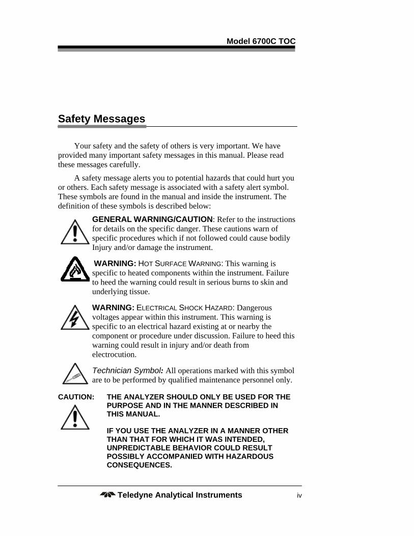
Safety Messages
Your safety and the safety of others is very important. We have provided many important safety messages in this manual. Please read these messages carefully.
A safety message alerts you to potential hazards that could hurt you or others. Each safety message is associated with a safety alert symbol. These symbols are found in the manual and inside the instrument. The definition of these symbols is described below:
GENERAL WARNING/CAUTION: Refer to the instructions for details on the specific danger. These cautions warn of specific procedures which if not followed could cause bodily Injury and/or damage the instrument.
WARNING: HOT SURFACE WARNING: This warning is specific to heated components within the instrument. Failure to heed the warning could result in serious burns to skin and underlying tissue.
WARNING: ELECTRICAL SHOCK HAZARD: Dangerous voltages appear within this instrument. This warning is specific to an electrical hazard existing at or nearby the component or procedure under discussion. Failure to heed this warning could result in injury and/or death from electrocution.
Technician Symbol: All operations marked with this symbol are to be performed by qualified maintenance personnel only.
CAUTION: THE ANALYZER SHOULD ONLY BE USED FOR THE PURPOSE AND IN THE MANNER DESCRIBED IN THIS MANUAL.
IF YOU USE THE ANALYZER IN A MANNER OTHER THAN THAT FOR WHICH IT WAS INTENDED, UNPREDICTABLE BEHAVIOR COULD RESULT POSSIBLY ACCOMPANIED WITH HAZARDOUS CONSEQUENCES.

High Temperature Combustion
Teledyne Analytical Instruments v
This manual provides information designed to guide you through the installation, calibration operation and maintenance of your new analyzer. Please read this manual and keep it available.
Occasionally, some instruments are customized for a particular application or features and/or options added per customer requests. Please check the front of this manual for any additional information in the form of an Addendum which discusses specific information, procedures, cautions and warnings that may be peculiar to your instrument.
Manuals do get lost. Additional manuals can be obtained from TI/AI at the address given in the Appendix. Some of our manuals are available in electronic form via the internet. Please visit our website at: www.teledyne-ai.com.
Model 6700C TOC
Teledyne Analytical Instruments vi
High Temperature Combustion
Teledyne Analytical Instruments vii
Additional Safety Information
All relevant precautions and safety remarks of the gas supplier must be observed:
General Safety Rules Legally Binding Safety Rules
In addition to safety rules outlined in this manual, all current environmental, technical, legal, and governmental regulation must be adhered to. General Inspection Requirements
General inspection of the Analyzer must be performed by a trained technician after each incidence of maintenance, repair, or service. Power Connections
The Analyzer may only be installed and connected to a main power supply according to the installation instructions provided in this manual. All power lines to the Analyzer must have switches to cut off the electricity. Spare Parts
Only options and parts specified by TAI may be used in performing maintenance or repair of the Analyzer.
Modifications and Alternations
Any modifications to the Analyzer or any of its options or parts must first be authorized by TAI. Responsibilities & Duties of the Supplier
The supplier is responsible for the safety of the product. However, such safety can only be reasonably guaranteed if the end user of the product adheres to the requirements and instructions stipulated in this manual.

Model 6700C TOC
Teledyne Analytical Instruments viii
Responsibilities & Duties of the End User
The end user is responsible to ensure that only trained, authorized personnel operate and maintain the Analyzer. The end user is responsible for self-training by reading and adhering to the instructions in this manual.
Instruction of Dangers
The end user is responsible to ensure that all personnel who operate and maintain the Analyzer are thoroughly instructed in its proper usage and have received knowledge of all safety precautions. Care & Maintenance
The end user is responsible to observe the recommended maintenance schedule.
Observation & Information
The end user is responsible to immediately inform the supplier if any additional risks, not addressed in this manual, are discovered.

High Temperature Combustion
Teledyne Analytical Instruments ix
Table of Contents
Additional Safety Information .................................................... vii
List of Figures ............................................................................... xi
List of Tables ............................................................................... xii
Introduction ................................................................................. 15
1.1 Overview 15
Operational Theory ..................................................................... 17
2.1 Measurement Principle 17
Installation and Startup ............................................................... 19
3.1 Installation 19
3.2 Non – Catalytic Reactor Packing 20
3.2.1 Identify Parts 20
3.2.2 Preparation of Combustion Reactor 22
3.2.2.1 Install Quartz Sleeve (Insert) 23
3.2.2.2 Loading Ceramic Wool Slices 23
3.3 Catalytic Reactor Packing 24
3.4 Inserting Reactor into Furnace 25
3.5 Startup of the Analyzer 27
3.6 Shutdown 28
Operation ..................................................................................... 29
4.1 Menus 29
4.2 Run Mode 29
4.3 Edit 30
4.3.1 Edit/Parameters 31
4.3.2 Edit/Alarms 32
4.4 Cal 32
4.4.1 Organic and Inorganic Carbon Standards 32

Model 6700C TOC
Teledyne Analytical Instruments x
4.4.2 Reagents 34
4.4.2.1 Preparation Of Sulfuric Acid Solution 34
4.4.3 NDIR Calibration (Gas Calibration) 34
4.4.4.“End-to End” Calibration 36
4.5 Chart 37
4.5.1 Scale 38
4.5.2 Last 24 Hours 38
4.5.3 Historical Data 39
4.6 Test 39
Maintenance ................................................................................ 41
5.1 Factory Assistance 41
5.2 Troubleshooting Guide 41
5.3 Module Service 42
5.3.1 NDIR Calibration 42
5.3.2 NDIR Service 42
5.3.3 Master Interface Board 47
5.3.4 D.C. Power Supply 47
5.3.5 Computer 48
5.3.6 Reactor Assembly and Gas/Liquid Separator 49
5.3.7 Mass Flow Controller 51
5.3.8 Metering Valve 52
5.3.9 Sparger 53
5.3.10 Injector Assembly 54
Appendix ...................................................................................... 57
A.1 Specifications 57
A-2 Recommended Spare Parts 58

High Temperature Combustion
Teledyne Analytical Instruments xi
List of Figures
Figure 2-1 Typical Flow Diagram ................................................... 18
Figure 3-1: Combustion Module Interior ........................................ 20
Figure 3-2: Installing Quartz Insert into Reactor ............................ 23
Figure 3-4: Catalyst Packing ......................................................... 24
Figure 3-5: Gas/Liquid Separator .................................................. 25
Figure 3-6: Filling Separator with DI Water .................................... 26
Figure 3-7: Attaching Reactor Top ................................................ 26
Figure 3-8: Top Retainer Installation ............................................. 27
Figure 4-1: Connecting Calibration Adapter .................................. 35
Figure 5-1: Removing the NDIR .................................................... 43
Figure 5-2: Removing the Master Interface Board Assembly ........ 47
Figure 5-3: DC Power Supply ........................................................ 48
Figure 5-4: Removing Computer Module ...................................... 49
Figure 5-5: Reactor Assembly and GLS ........................................ 50
Figure 5-6: Typical Mass Flow Controller ..................................... 51
Figure 5-7: Metering Valve ............................................................ 52
Figure 5-8: Sparger ....................................................................... 53
Figure 5-9: Injector Assembly ........................................................ 55

Model 6700C TOC
Teledyne Analytical Instruments xii
List of Tables
Table 3-1: Preparation of Standards (TOC) .................................. 33
Table 3-2: Preparation of Standards (TN) ..................................... 33
Table 3-3: Preparation of Standards (TIC) .................................... 33
Table 5-1 Troubleshooting ............................................................ 42

High Temperature Combustion
Teledyne Analytical Instruments xiii
DANGER COMBUSTIBLE GAS USAGE
WARNING
This is a general purpose instrument designed for use in a non-hazardous area. It is the customer's responsibility to ensure safety especially when combustible gases are being analyzed since the potential of gas leaks always exist.
The customer should ensure that the principles of operating this equipment are well understood by the user. Misuse of this product in any manner, tampering with its components, or unauthorized substitution of any component may adversely affect the safety of this instrument.
Since the use of this instrument is beyond the control of Teledyne Analytical Instruments, referred as TAI, no responsibility by TAI, its affiliates, and agents for damage or injury from misuse or neglect of this equipment is implied or assumed.


High Temperature Combustion Operational Theory
Teledyne Analytical Instruments 15
Introduction
1.1 Overview
Teledyne Analytical Instruments (TAI) offers a variety of Total Organic Carbon (TOC) analyzers to serve a wide range of applications. The Model 6700C High Temperature Combustion TOC Analyzer provides accurate and reliable on-line TOC and TN analysis and is configured to provide maximum utility using an advanced Microsoft Windows based CE computer with touch screen.
This manual includes all necessary information to help you install, operate and service your Analyzer. The analyzer is designed for easy Operator Maintenance and does not normally require field service.
The Windows-based CE operator interface provides easy, fast and reliable analysis. This manual includes all necessary information to help you install, operate and service your Analyzer.
The Model 6700C TOC-True Analyzer is designed for easy operation and maintenance. Particular attention has been devoted to the design, whereby any module can be replaced by the operator within 15 minutes. Components such as the NDIR units have been specifically designed with no moving parts and use a corrosion resistant design to further reduce maintenance tasks.
The analyzer is suitable for both General Purpose and/or Hazardous Area classifications, if properly configured with required safety equipment.
Operating the analyzer is easy. It uses a standard, industrial Windows CE computer programmed for complete automatic control (there are no operator manual adjustments). Operators are advised to study pertinent chapters in this manual to fully utilize the capabilities of the analyzer and avoid problems that could be associated with any instrument.
Operational Theory Model 6700C TOC
Teledyne Analytical Instruments 16
The Analyzer is designed for monitoring of Total Organic Carbon (TOC) in water. This intended use involves carefully following the instructions provided in this manual and observing all indicated warnings, hints and instructions.
High Temperature Combustion Operational Theory
Teledyne Analytical Instruments 17
Operational Theory
2.1 Measurement Principle
Refer to Figure 2-1.
The Injector is connected with all possible flow paths and separated from sample and reagent liquids by a 10 ml volume loop. One end of the volume loop is connected to the injector, the other is connected to the center port of a 10 port Rotary Valve.
A typical sequence of events for the injection unit for measurement of TOC is as follows:
The Rotary Valve will be engaged, opening a flow path to the drain line of the analyzer. The Injector is then sent to the home or empty position.
The DI Valve is turned on and a small amount of DI is then picked up by the Injector. The DI Valve is then turned off and the Rotary Valve is turned to the Acid Port where the Injector pulls a small amount of acid into the loop. The Rotary Valve is then turned to the sample port and sample is pulled into the loop. The Rotary Valve is turned to the Sparge Port and the Injector then pushes the sample and acid to the sparger through the Sparger Port, where the pH is lowered to approximately 2.0 and inorganic carbon is removed.
After the sparge time is completed, the Injector pulls the inorganic free sample volume from the sparger. The Rotary Valve is then turned to the Reactor Port. The Injector pumps the sample into the reactor at a flow rate of one (1) drop in approximately seven (7) seconds.
The sample is oxidized in the High Temperature Furnace where organic carbon is converted to CO2 and the gases are directed to a cooler condenser where excess water is removed, and then on to the NDIR where the CO2 is measured and TOC is determined. The gases are then passed to vent.

Operational Theory Model 6700C TOC
Teledyne Analytical Instruments 18
Figure 2-1 Typical Flow Diagram
High Temperature Combustion Installation/Startup
Teledyne Analytical Instruments 19
Installation and Startup
The Model 6700C is often configured for a specific application as requested by the customer. Optional equipment and any application specific configuration of this instrument will be described in an addendum to this manual. Please check the front of this manual for any addenda that may be included.
3.1 Installation
Installation of the Total Organic Analyzer includes:
1. Unpacking
2. Mounting
3. Gas Connections
4. Electrical Connections
5. Testing the System
6. Unpacking the Analyzer
The analyzer is shipped with all the materials you need to install and prepare the system for operation. Carefully unpack the analyzer and inspect it for damage and immediately report any damage to the shipping agent.
Note: If the Reactor has been packed and shipped separately, please follow the instructions below to properly prepare and install the Reactor.
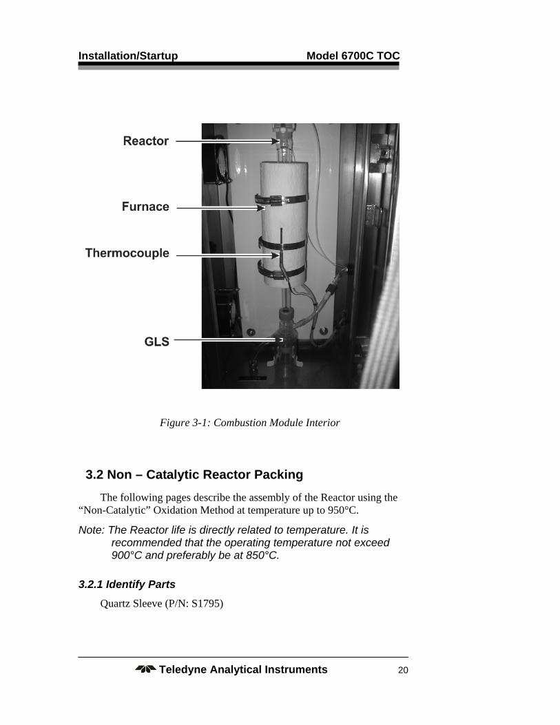
Open the door of the Combustion Module. Figure 3-1 shows the reactor properly installed in the furnace.
See also Section 5.3.6.
Installation/Startup Model 6700C TOC
Teledyne Analytical Instruments 20
Figure 3-1: Combustion Module Interior
3.2 Non – Catalytic Reactor Packing
The following pages describe the assembly of the Reactor using the “Non-Catalytic” Oxidation Method at temperature up to 950°C.
Note: The Reactor life is directly related to temperature. It is recommended that the operating temperature not exceed 900°C and preferably be at 850°C.
3.2.1 Identify Parts
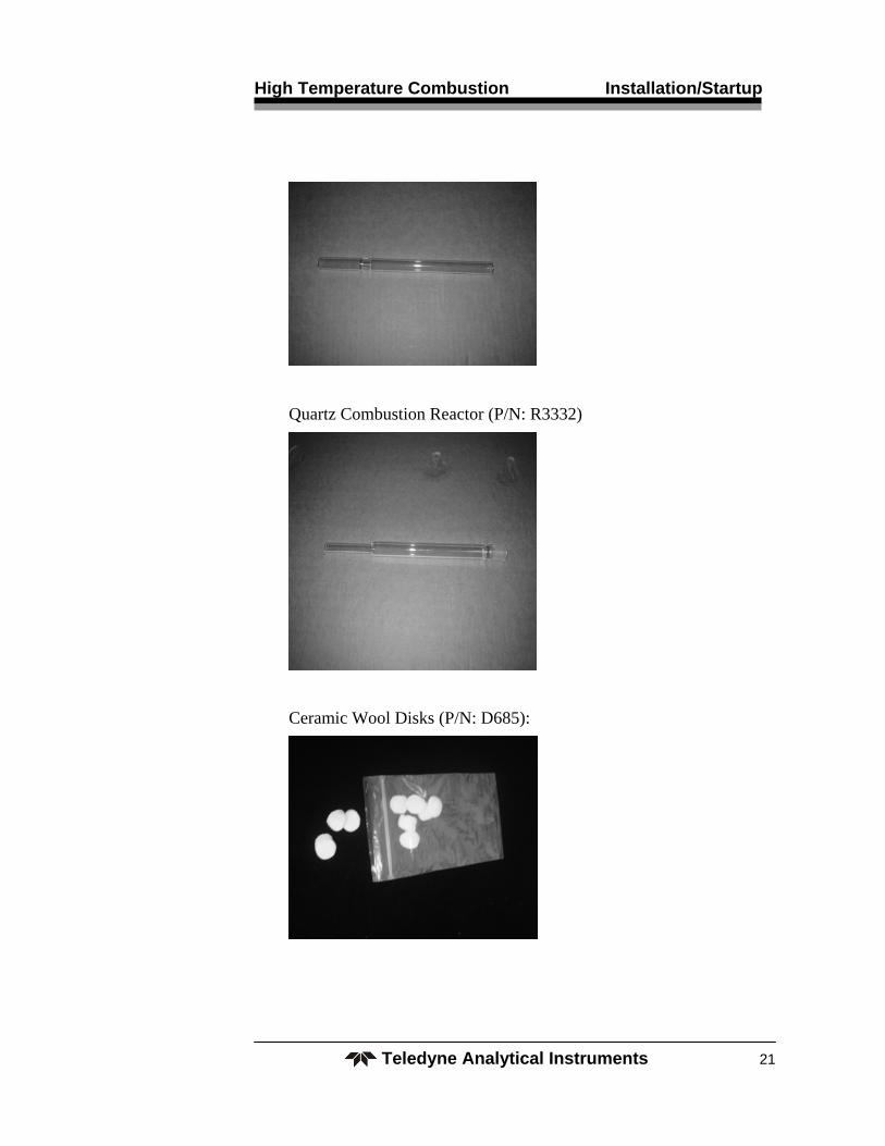
Quartz Sleeve (P/N: S1795)
High Temperature Combustion Installation/Startup
Teledyne Analytical Instruments 21
Quartz Combustion Reactor (P/N: R3332)
Ceramic Wool Disks (P/N: D685):

Installation/Startup Model 6700C TOC
Teledyne Analytical Instruments 22
Glass Reactor Top (P/N: R3331)
Top Retainer (P/N: R3350)
3.2.2 Preparation of Combustion Reactor
Note: The Reactor may be operated with platinum catalyst at 680º to 750º C or non-catalytically at higher temperature (850ºC recommended). The standard configuration is non-catalytic, although catalyst may be purchased and used, if an unusually difficult to oxidize sample is encountered.
TAI recommends to first raise the temperature to 900º C (max.) to determine if satisfactory performance is attained before packing the Reactor with catalyst. The Reactor temperature profile is 100º C higher than the temperature controller set point in certain areas of the Reactor.
Reactor life is highly dependent on operating temperature and the operator is cautioned not to exceed these temperature set points in order to prevent damage to the Reactor. The Reactor should be maintained at temperature and not turned on and off in order to minimize stress failure of the Reactor over a period of time.
High Temperature Combustion Installation/Startup
Teledyne Analytical Instruments 23
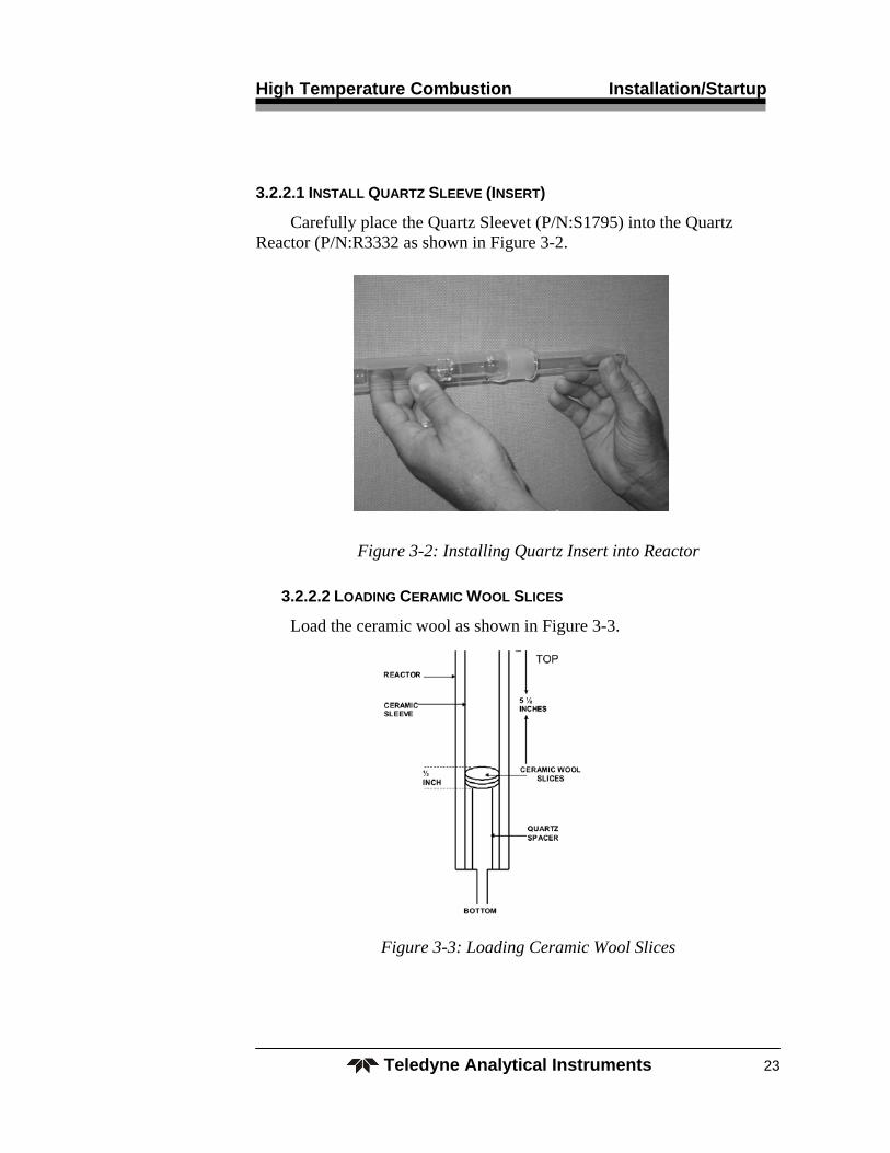
3.2.2.1 INSTALL QUARTZ SLEEVE (INSERT)
Carefully place the Quartz Sleevet (P/N:S1795) into the Quartz Reactor (P/N:R3332 as shown in Figure 3-2.
Figure 3-2: Installing Quartz Insert into Reactor
3.2.2.2 LOADING CERAMIC WOOL SLICES
Load the ceramic wool as shown in Figure 3-3.
Figure 3-3: Loading Ceramic Wool Slices

Installation/Startup Model 6700C TOC
Teledyne Analytical Instruments 24
CAUTION: Be careful to slowly place the assembly in a vertical position, AVOIDING A RAPID DROP of the Ceramic Sleeve and Spacer to the bottom of the Reactor.
If not carefully inverted, the Ceramic Sleeve and Spacer will damage the bottom of the Reactor by dropping too fast.
3.3 Catalytic Reactor Packing
The following figures represent the packing used for the catalytic oxidation method.
The optimum furnace operating temperature is between 680°C and 750°C. The lower the temperature, the longer the life of the catalyst.
Figure 3-4: Catalyst Packing
1. Loosely pack Ceramic Wool at bottom of Reactor base.
2. Pour catalyst into Reactor.
3. Loosely pack Ceramic Wool on top of catalyst.

High Temperature Combustion Installation/Startup
Teledyne Analytical Instruments 25
3.4 Inserting Reactor into Furnace
Carefully insert the Reactor Assembly into the Furnace and secure the Assembly by following the procedure outlined in Figures 3-5 through 3-8.
Finger-tighten the Gas/Liquid Separator (P/N: G608) to Reactor, as shown below in Figure 3-5.
Figure 3-5: Gas/Liquid Separator
Connect the Combustion Module Drain port to a facility gravity drain with a 1 inch air break between the end of the drain line and any liquids in the collection vessel (jar, facility drain) in order to prevent a “vapor lock”. This drain line should be routed in a straight fashion and free of kinks or restrictions thereby allowing the liquids to drain freely.
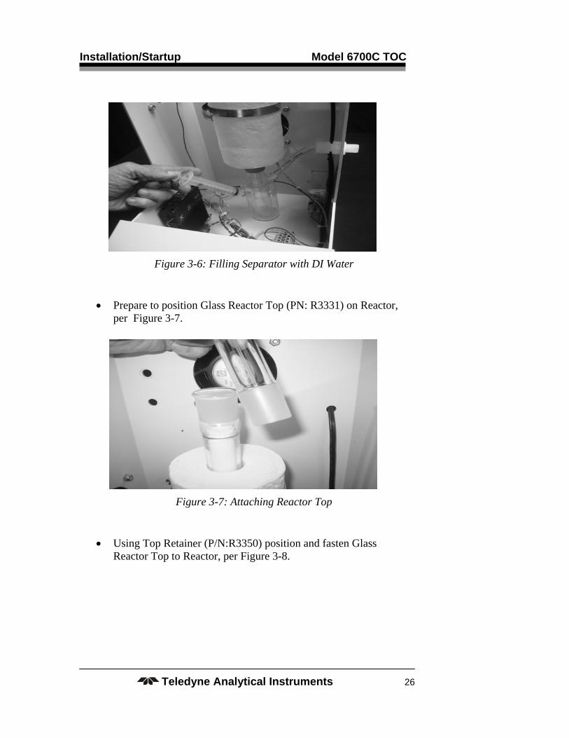
Prepare the Gas/Liquid Separator by filling it with D.I. water until it overflows to drain, as shown in Figure 3-6. This provides proper sealing of the reacted sample gases.
Installation/Startup Model 6700C TOC
Teledyne Analytical Instruments 26
Figure 3-6: Filling Separator with DI Water
Prepare to position Glass Reactor Top (PN: R3331) on Reactor, per Figure 3-7.
Figure 3-7: Attaching Reactor Top
Using Top Retainer (P/N:R3350) position and fasten Glass Reactor Top to Reactor, per Figure 3-8.

High Temperature Combustion Installation/Startup
Teledyne Analytical Instruments 27
Figure 3-8: Top Retainer Installation
3.5 Startup of the Analyzer
Before starting the analyzer, please check the following:
Air/oxygen supply – This must provide a constant pressure of 15 ± 2 psi, ultra-pure oxygen or hydrocarbon and CO2–free air at a flow rate up to 300 cc/minute. Pre-purified air may be used with optional Zero Air Generator which requires Instrument Air or Oxygen Generator which requires electricity only.
Drain Line – Check to see if the Drain Line is sloped downward and is free of kinks, loops and allows normal vented gravity flow with an air break to an open receptacle (jar, pipe, etc.).
Vents – Vent lines must be properly installed and vented to atmospheric conditions and not allowed to have either a restriction or a pumping of exhaust flow, as either of these conditions may result in improper analyzer operation.
Installation/Startup Model 6700C TOC
Teledyne Analytical Instruments 28
CAUTION: FAILURE TO OBSERVE THIS WILL RESULT IN IMPROPER OPERATION OR A SAFETY HAZARD.
ELECTRICAL – Assure proper electrical installation.
SAFETY – All customer and TAI specified safety measures are followed.
After all of the above checks, turn analyzer ON by activating the facility power switch. Thereafter, follow the MENU on the display.
Ultimate stability of the analyzer will occur within a few hours, although initial operation may proceed in one hour after the reactor temperature reaches its set point.
Immerse the line from “sample” port of the Analyzer into a D.I. water container. Immerse the acid line from the “ACID IN” port of the Analyzer into an ACID container. (2N HCl)
Note: For “TC” only operation, No Acid is Required.
3.6 Shutdown
Prior to shutdown of the analyzer or service on the Reactor, flush D.I. water through all sample and reagent lines.
CAUTION: FAILURE TO OBSERVE ADEQUATE FLUSHING COULD RESULT IN HARMFUL ACID BURNS AND/OR A REACTOR CLOG.

High Temperature Combustion Operation
Teledyne Analytical Instruments 29
Operation
After proper installation the instrument must be calibrated. Following calibration, the instrument is ready to be placed “ON-LINE”.
Note: For any non–standard or specific operational procedures, please refer to the “INSTALLATION” and any addenda that accompanies this manual for details on your specific application. Items such as valving, stream sequencing, automatic calibration, etc. are non-standard items and will be described in an attached addendum.
4.1 Menus
The advanced design of the Model 6700C Analyzer eliminates complicated, routine, and sometimes confusing Menus. The operator/ software interface is as simple as the analyzer’s construction, operation, and most importantly, maintenance.
The analyzer has no manual adjustments. Complete calibration and operation are computer controlled by the operator, following menu prompting and selection of the operation of choice.
The following menu and operation descriptions are intended to guide the Operator through all the functions of the Model 6700C TOC High Temperature Combustion Analyzer.
After primary power (110/220VAC) has been applied to the Analyzer and self-diagnostic procedure has been completed, the system automatically boots up to the following Run Screen. If not, turn main power OFF, then ON to reboot.
4.2 Run Mode
Run is the normal analysis mode. The display indicates the current TOC or both TOC and TN (optional) values, [IR] IR response, and [Flow] carrier gas flow rate.

Operation Model 6700C TOC
Teledyne Analytical Instruments 30
Although your analyzer has been configured for optimum performance in your application, on initial startup the setup parameters should be verified (Consult Factory Settings for Your Application).
4.3 Edit
The Edit menu contains functions that allow you to configure the instrument to your application. Within the EDIT menu you can:
Set instrument parameters
Set Alarms and setpoints
Benchmark scheduling
Autocal scheduling
Set volumes
Define species
From the Run Screen, select [EDIT]. The following menu will appear:
High Temperature Combustion Operation
Teledyne Analytical Instruments 31
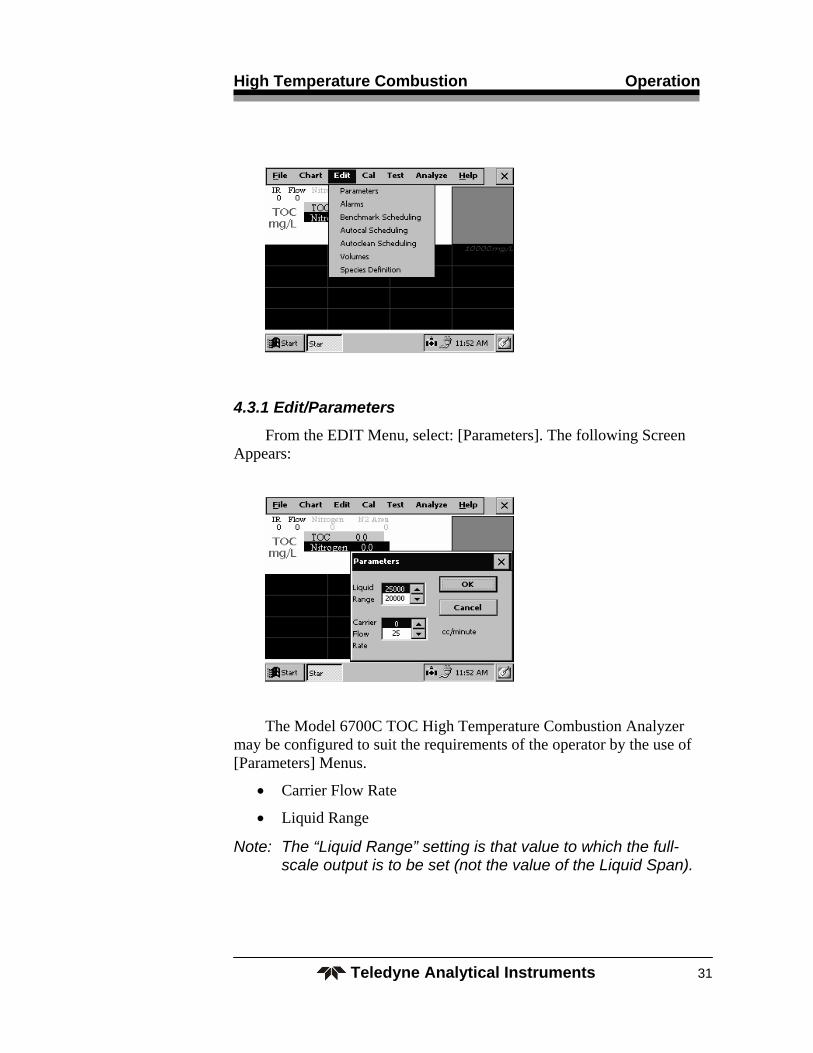
4.3.1 Edit/Parameters
From the EDIT Menu, select: [Parameters]. The following Screen Appears:
The Model 6700C TOC High Temperature Combustion Analyzer may be configured to suit the requirements of the operator by the use of [Parameters] Menus.
Carrier Flow Rate
Liquid Range
Note: The “Liquid Range” setting is that value to which the full-scale output is to be set (not the value of the Liquid Span).

Operation Model 6700C TOC
Teledyne Analytical Instruments 32
4.3.2 Edit/Alarms
The next recommended settings to be verified or set are the Alarm Settings.
From the [Edit] Menu, select [Alarms]. The following Menu appears:
From this menu you can verify or select the desired Alarm points.
4.4 Cal
Although the instrument has been calibrated to your specifications at the factory, it should be rechecked after satisfactory installation and periodically calibrated as suggested for your application.
The analyzer calibration is performed by an “end-to-end” method, whereby a known chemical standard solution is introduced to the analyzer and the analyzer is “spanned” to that value.
4.4.1 Organic and Inorganic Carbon Standards
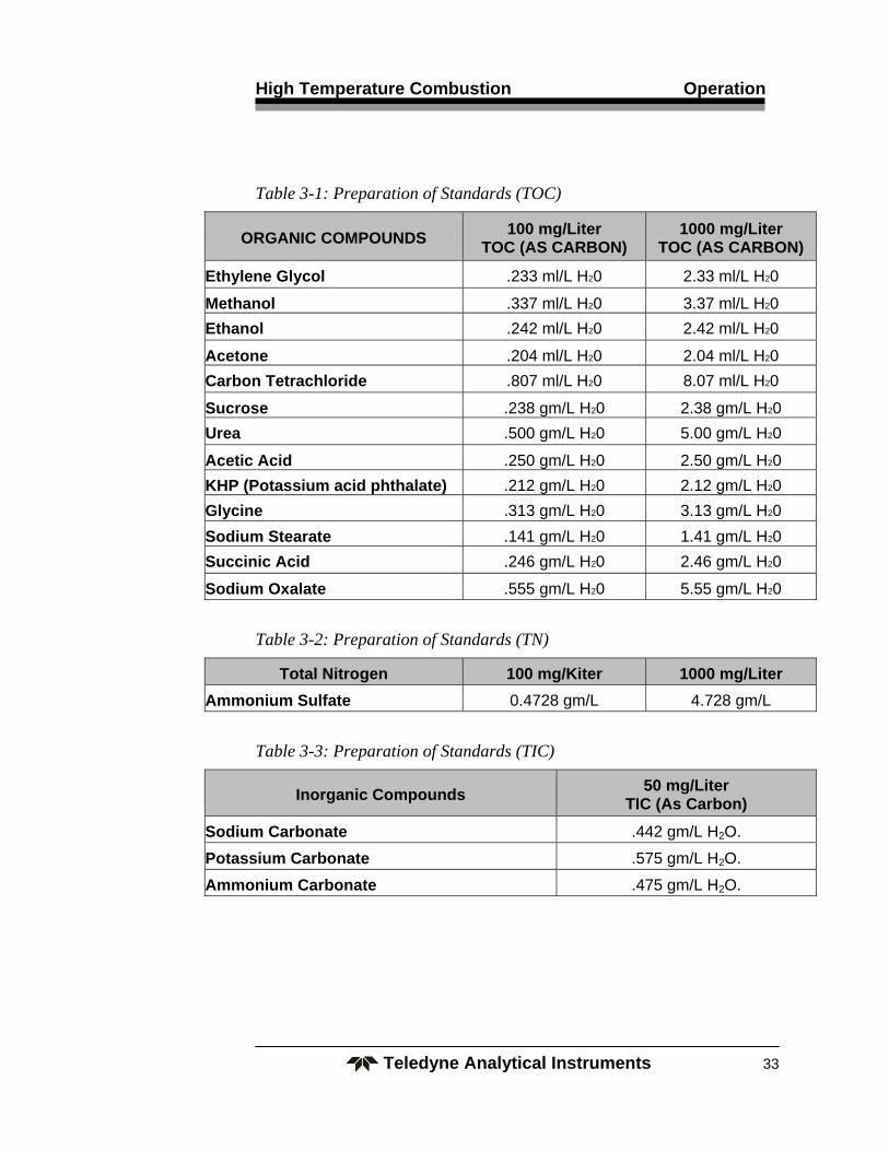
KHP (Potassium Hydrogen Phthalate) is recommended for the organic carbon standard solution. Sodium Carbonate is recommended for the inorganic carbon standard. Table 3-1 provides the concentration to be used for two ranges of different chemical compounds (organic & inorganic carbon). Using a ratio of these concentrations will provide other ranges for the span solution.
High Temperature Combustion Operation
Teledyne Analytical Instruments 33
Table 3-1: Preparation of Standards (TOC)
ORGANIC COMPOUNDS 100 mg/Liter
TOC (AS CARBON) 1000 mg/Liter
TOC (AS CARBON)
Ethylene Glycol .233 ml/L H20 2.33 ml/L H20
Methanol .337 ml/L H20 3.37 ml/L H20
Ethanol .242 ml/L H20 2.42 ml/L H20
Acetone .204 ml/L H20 2.04 ml/L H20
Carbon Tetrachloride .807 ml/L H20 8.07 ml/L H20
Sucrose .238 gm/L H20 2.38 gm/L H20
Urea .500 gm/L H20 5.00 gm/L H20
Acetic Acid .250 gm/L H20 2.50 gm/L H20
KHP (Potassium acid phthalate) .212 gm/L H20 2.12 gm/L H20
Glycine .313 gm/L H20 3.13 gm/L H20
Sodium Stearate .141 gm/L H20 1.41 gm/L H20
Succinic Acid .246 gm/L H20 2.46 gm/L H20
Sodium Oxalate .555 gm/L H20 5.55 gm/L H20
Table 3-2: Preparation of Standards (TN)
Total Nitrogen 100 mg/Kiter 1000 mg/Liter
Ammonium Sulfate 0.4728 gm/L 4.728 gm/L
Table 3-3: Preparation of Standards (TIC)
Inorganic Compounds 50 mg/Liter
TIC (As Carbon)
Sodium Carbonate .442 gm/L H2O.
Potassium Carbonate .575 gm/L H2O.
Ammonium Carbonate .475 gm/L H2O.

Operation Model 6700C TOC
Teledyne Analytical Instruments 34
4.4.2 Reagents
The following provides reagent preparation guides for acid reagent.
Sulfuric Acid is the acid of choice. Phosphoric Acid may NOT be used in the Model 6700C TOC High Temperature Combustion Analyzer.
4.4.2.1 PREPARATION OF SULFURIC ACID SOLUTION
TAI recommends the use of Ethylene Glycol and Ammonium Sulfate, but the user may choose another standard from the above tables. The container used should be flushed with distilled or deionized (DI) water. Add 56ml of 66 Baume sulfuric acid to 1 liter of D. I. Recommended Reagent Container size is 4 Liter.
CAUTION: ALWAYS ADD ACID TO WATER TO KEEP FROM SPLASHING OR SPRAYING REACTION COMPONENTS.
4.4.3 NDIR Calibration (Gas Calibration)
Note: On the initial Startup or after a prolonged storage, the gas calibration should be checked and, if necessary, performed prior to liquid calibration (see Section 3.5).
From Menu, select [CAL]. The following screen will appear:
Select [Sensor].
High Temperature Combustion Operation
Teledyne Analytical Instruments 35
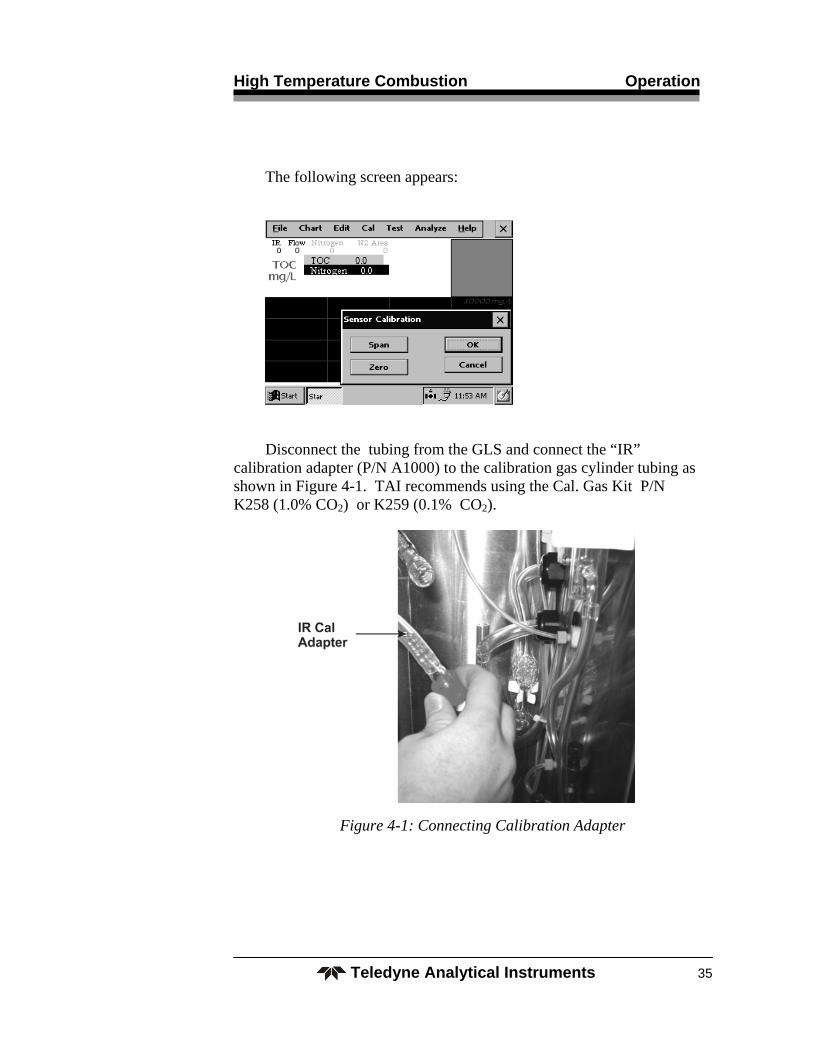
The following screen appears:
Disconnect the tubing from the GLS and connect the “IR” calibration adapter (P/N A1000) to the calibration gas cylinder tubing as shown in Figure 4-1. TAI recommends using the Cal. Gas Kit P/N K258 (1.0% CO2) or K259 (0.1% CO2).
Figure 4-1: Connecting Calibration Adapter

Operation Model 6700C TOC
Teledyne Analytical Instruments 36
To set IR “Zero”:
Flow 200cc/minute oxygen (or CO2 free air) for 5 minutes.
Allow the NDIR reading to stabilize. Select [ZERO]. The NDIR Reading will be set to 0.
To set IR “Span”, a gas calibration standard mixture of 1% CO2 in pure nitrogen is required for the 6 inch (shorter) IR bench. A gas mixture of 0.1% CO2 in pure nitrogen is required for the longer (15 inch) bench.
Flow 200 cc/minute of this cal gas.
Allow the NDIR reading to stabilize and then select [SPAN]. The NDIR reading will be set to 10,000.
Select [OK] to save or [CANCEL] to reject the calibration setting.
The NDIR has now been properly calibrated. Re-connect tubing as before.
4.4.4.“End-to End” Calibration
Note: On the initial Startup, the gas calibration should be checked and, if necessary, performed prior to liquid calibration.
From Menu, select [CAL]. The following screen will appear:

High Temperature Combustion Operation
Teledyne Analytical Instruments 37
Select [Liquid]. The following screen appears:
Select “ZERO”. D. I. water is automatically introduced to the analyzer. The user will be notified upon completion.
Select the span solution value, and press [Span] to introduce the solution and then select [SPAN]. If the calibration is acceptable, select [OK] or [CANCEL] if not acceptable.
The analyzer is now calibrated and ready to run samples.
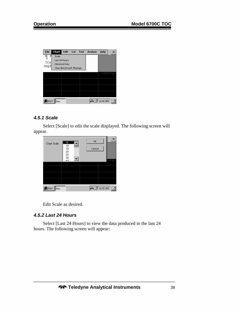
4.5 Chart
Historical Data may be obtained from the Chart menu. The following data can be edited or recalled:
Scale – set the scale for the screen
Last 24 hours – Review of data taken within the last 24 hours
Historical Data – Recall archived data
To enter the menu, select [Chart] from the screen. The following menu will appear.
Operation Model 6700C TOC
Teledyne Analytical Instruments 38
4.5.1 Scale
Select [Scale] to edit the scale displayed. The following screen will appear.
Edit Scale as desired.
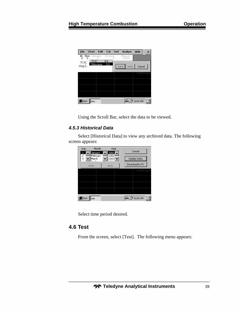
4.5.2 Last 24 Hours
Select [Last 24 Hours] to view the data produced in the last 24 hours. The following screen will appear:
High Temperature Combustion Operation
Teledyne Analytical Instruments 39
Using the Scroll Bar, select the data to be viewed.
4.5.3 Historical Data
Select [Historical Data] to view any archived data. The following screen appears:
Select time period desired.
4.6 Test
From the screen, select [Test]. The following menu appears:

Operation Model 6700C TOC
Teledyne Analytical Instruments 40
Select [System Diagnostics]. The following menu appears:
From this screen the operator may perform individual testing of components related to functionality and settings.
See Section 5 for information on troubleshooting and maintenance.
High Temperature Combustion Maintenance
Teledyne Analytical Instruments 41
Maintenance
Aside from normal cleaning and checking for leaks at the connections, the Model 6700C should not require any maintenance beyond recalibration, as described in Chapter 4, Operation.
5.1 Factory Assistance
For factory assistance, contact TAI Customer Assistance via phone, fax, or email: Teledyne Analytical Instruments 16830 Chestnut Street City of Industry, California 91748-1020, USA Tel: 626-961-9221 or 626-934-1500 Fax: 626-961-2538 or 626-934-1651 Toll free: 888-789-8168 Email: [email protected]
Note: Please provide the analyzer model and serial number when contacting Customer Service.
5.2 Troubleshooting Guide
Prior to performing detailed troubleshooting procedures detailed below, it is suggested that the operator first perform computer-aided testing of the analyzer using built-in test routine as described in Section 4.6.
If you are experiencing trouble with your instrument, please refer to the following checklist:
Maintenance Model 6700C TOC
Teledyne Analytical Instruments 42
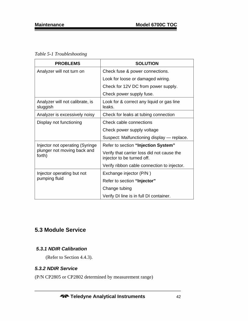
Table 5-1 Troubleshooting
PROBLEMS SOLUTION
Analyzer will not turn on Check fuse & power connections.
Look for loose or damaged wiring.
Check for 12V DC from power supply.
Check power supply fuse.
Analyzer will not calibrate, is sluggish
Look for & correct any liquid or gas line leaks.
Analyzer is excessively noisy Check for leaks at tubing connection
Display not functioning Check cable connections
Check power supply voltage
Suspect: Malfunctioning display — replace.
Injector not operating (Syringe plunger not moving back and forth)
Refer to section “Injection System”
Verify that carrier loss did not cause the injector to be turned off.
Verify ribbon cable connection to injector.
Injector operating but not pumping fluid
Exchange injector (P/N )
Refer to section “Injector”
Change tubing
Verify DI line is in full DI container.
5.3 Module Service
5.3.1 NDIR Calibration
(Refer to Section 4.4.3).
5.3.2 NDIR Service
(P/N CP2805 or CP2802 determined by measurement range)
High Temperature Combustion Maintenance
Teledyne Analytical Instruments 43
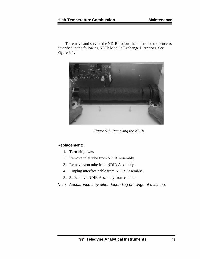
To remove and service the NDIR, follow the illustrated sequence as described in the following NDIR Module Exchange Directions. See Figure 5-1.
Figure 5-1: Removing the NDIR
Replacement:
1. Turn off power.
2. Remove inlet tube from NDIR Assembly.
3. Remove vent tube from NDIR Assembly.
4. Unplug interface cable from NDIR Assembly.
5. 5. Remove NDIR Assembly from cabinet.
Note: Appearance may differ depending on range of machine.
Maintenance Model 6700C TOC
Teledyne Analytical Instruments 44
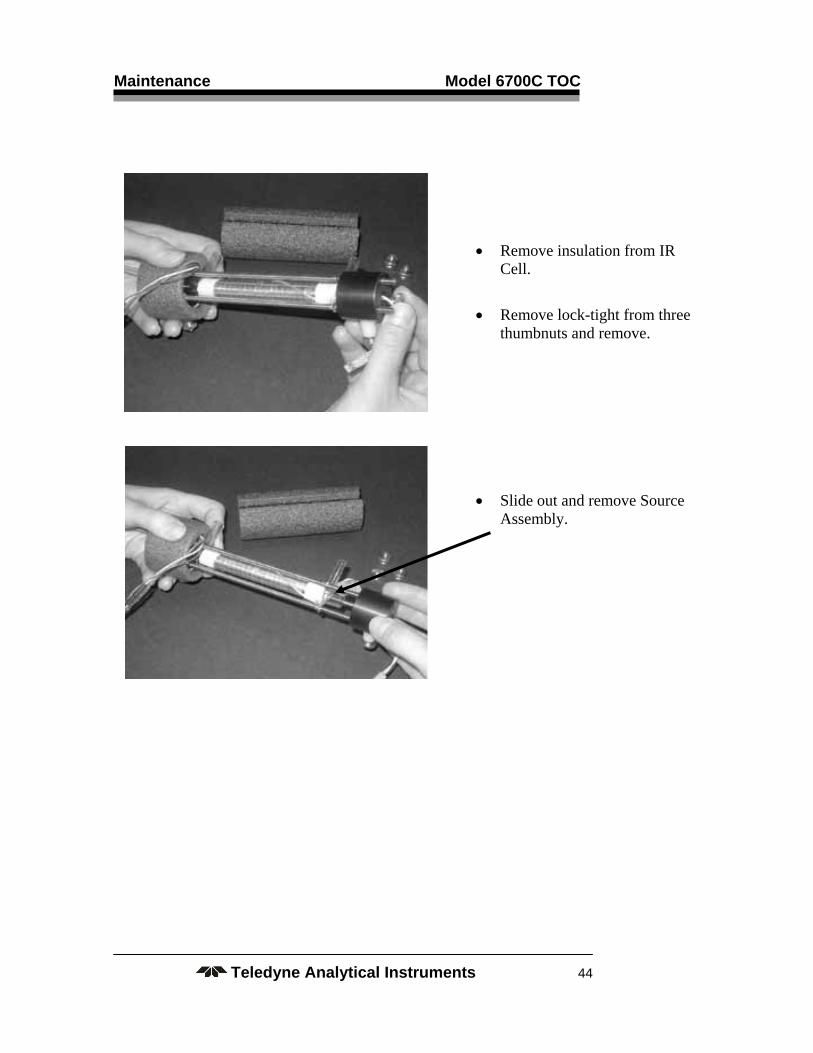
Remove insulation from IR Cell.
Remove lock-tight from three thumbnuts and remove.
Slide out and remove Source Assembly.

High Temperature Combustion Maintenance
Teledyne Analytical Instruments 45
Remove IR Cell Assembly
Note:
a. ‘O’-Rings in each of
Detector Assembly (left) and Source Assembly (right).
b. Sapphire windows located under ‘O’-Rings

Maintenance Model 6700C TOC
Teledyne Analytical Instruments 46
*Remove ‘O’-Ring and Sapphire window taking care to avoid scratching sapphire window.
*Recommend using toothpick.
Clean sapphire windows with
a soft, lintless tissue (use DI water, if necessary).
To Reassemble:
Install IR Cell.
Install Source Assembly end piece.
Note: Large outlet port goes into Detector Assembly (left)
Insert lock-tight on three thumbnuts to prevent back off.
Install insulation. Replace assembly as before.
Recalibrate NDIR (Section 4.4.4).

High Temperature Combustion Maintenance
Teledyne Analytical Instruments 47
5.3.3 Master Interface Board
(P/N B718 & P/N B717)
The Master Control Panel has no field adjustment. If malfunctioning, exchange modules by using the following instructions. See Figure 5-2.
Figure 5-2: Removing the Master Interface Board Assembly
Procedure:
1. Turn off power.
2. Remove plastic cover.
3. Disconnect connectors.
4. Remove panel.
5.3.4 D.C. Power Supply
(P/N P1506)
The power supply has no field adjustment. If malfunctioning, replace the module (P/N P1506) using the directions below. Refer to Figure 5-3.
Procedure:
1. Turn off power.
2. Remove plastic cover.

Maintenance Model 6700C TOC
Teledyne Analytical Instruments 48
3. Disconnect connectors.
4. Slide Power Supply off the Din Rail.
5. Remove Power Supply Module.
6. Replace Power Supply Module.
7. Reverse steps for installation.
8. Recalibrate liquid and span values.
Figure 5-3: DC Power Supply
5.3.5 Computer
If malfunctioning, exchange Computer Module using the directions below. See Figure 5-4.
Procedure:
1. Turn off power
2. Disconnect electrical connectors.
3. Remove screws holding Module in place.
4. Remove module.
5. 5. Install new CE Computer in reverse disassembly instruction procedure steps. Recalibrate liquid zero and span values.

High Temperature Combustion Maintenance
Teledyne Analytical Instruments 49
6. 6. Recalibrate liquid Zero and Span.
Figure 5-4: Removing Computer Module
5.3.6 Reactor Assembly and Gas/Liquid Separator
(P/N R3332) Reactor (P/N G608) GLS
If Reactor is malfunctioning or GLS is broken, use the following procedure for removal. Also, see Section 3.2.2 for information on repacking the Reactor. See Figure 5-5.
Procedure:
Replacement
1. Turn off power to Reactor.
2. Verify ambient temperature. The Reactor temperature is displayed at the top center of the display.
CAUTION: HOT SURFACES! WEAR GLOVES TO AVOID SEVERE BURNS.

Maintenance Model 6700C TOC
Teledyne Analytical Instruments 50
Figure 5-5: Reactor Assembly and GLS
3. Remove GLS.
Loosen fitting.
Raise Reactor until the Reactor bottom clears the GLS.
Remove GLS.
4. Remove Reactor top piece.
5. Remove back plate nuts.
High Temperature Combustion Maintenance
Teledyne Analytical Instruments 51
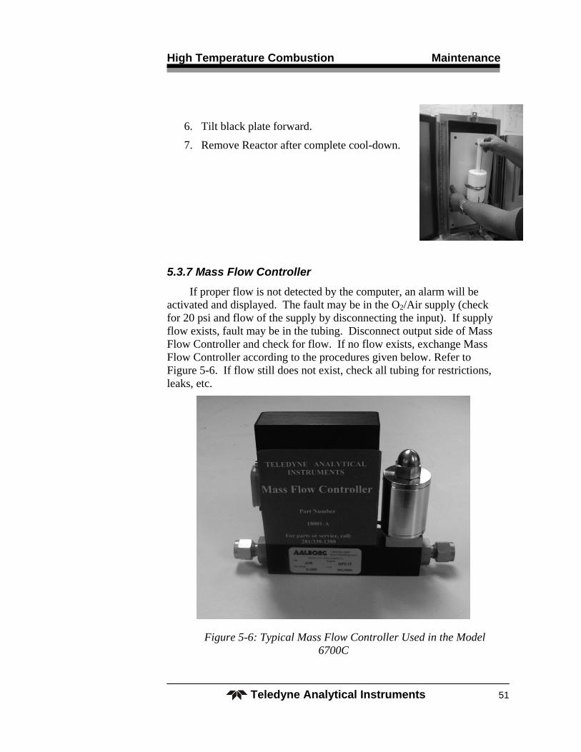
6. Tilt black plate forward.
7. Remove Reactor after complete cool-down.
5.3.7 Mass Flow Controller
If proper flow is not detected by the computer, an alarm will be activated and displayed. The fault may be in the O2/Air supply (check for 20 psi and flow of the supply by disconnecting the input). If supply flow exists, fault may be in the tubing. Disconnect output side of Mass Flow Controller and check for flow. If no flow exists, exchange Mass Flow Controller according to the procedures given below. Refer to Figure 5-6. If flow still does not exist, check all tubing for restrictions, leaks, etc.
Figure 5-6: Typical Mass Flow Controller Used in the Model 6700C

Maintenance Model 6700C TOC
Teledyne Analytical Instruments 52
Procedure:
1. Shut off Power to Instruments.
2. Shut off all gas to analyzer and bleed system for “0” pressure.
3. Disconnect fittings/tubing.
4. Loosen screws holding Module in-place.
5. Remove Module.
6. Recalibrate analyzer after re-installation of exchange Module.
Note: Mass Flow Controllers of different manufacture may be used. Include the manufacturer, make and model information when communicating with TAI Customer Service.
5.3.8 Metering Valve
If no O2/air flow to the Sparger is observed (no bubbles), check for tubing and fitting leaks or restrictions. Adjust the Metering Valve being careful to return to previous indicated bubble rate. If flow cannot be restored, replace the Metering Valve according to the procedure given below. Refer to Figure 5-7.
Figure 5-7: Metering Valve

High Temperature Combustion Maintenance
Teledyne Analytical Instruments 53
Procedure:
1. Turn carrier gas (Air/O2) OFF.
2. Turn Pumps OFF.
3. Remove fittings and tubing.
4. Remove Metering Valve.
5. Recalibrate TIC if TIC and/or TOC–TRUE analysis is required. Only NPOC analysis does not require recalibration.
6. Reinstall Metering Valve in reverse order.
5.3.9 Sparger
The Sparger may be removed for cleaning with detergent and subsequent flushing with DI water. If the Sparger inner glass body is leaking (cracked glass, etc.), or is clogged beyond cleaning, replace the Sparger according to the procedure given below. Refer to Figure 5-8.
Figure 5-8: Sparger

Maintenance Model 6700C TOC
Teledyne Analytical Instruments 54
Procedure:
CAUTION: OBSERVE NORMAL PRECAUTIONS WHEN HANDLING ACIDS.
Replacement
1. Turn machine OFF.
2. Turn carrier gas (Air/O2) OFF.
3. Remove and drain tubing and Sparger.
4. Remove Sparger from spring clips.
Cleaning
1. Run warm water through tubing to flush out any solid contamination.
2. Reinstall Sparger in reverse order.
5.3.10 Injector Assembly
To remove the Injector Assembly (See Figure 5-9):
1. Turn off power
2. Disconnect all tubing
3. Remove Injector
4. Reinstall new injector in reverse order

High Temperature Combustion Maintenance
Teledyne Analytical Instruments 55
Figure 5-9: Injector Assembly

Maintenance Model 6700C TOC
Teledyne Analytical Instruments 56
Percent Oxygen Analyzer Appendix
Teledyne Analytical Instruments 57
Appendix
A.1 Specifications
(The following specifications are nominal and depend on the actual application).
Measuring Method: TC (Total Carbon) – High Temperature Combustion. TOC (Total Organic Carbon) acidification and sparging to eliminate inorganic carbon interference.
Range: 0-100 through 0-10,000 ppm, full scale. (Range changes often require carrier gas adjustments. This analyzer uses the precision of computer controlled mass flow controllers to eliminate operator error and the use of inaccurate mechanical flow meters.)
Display: Windows with Paperless Chart Recorder
Data Handling: RS-232C, RS-485
Output: 4-20 mA
Alarms: Two alarm levels One master fault alarm
Response Time: Application dependent
Repeatability: ±3% FS (std. dev. 1 sigma)
Zero/Span Stability: ±3% FS
Linearity: ±3% FS
Inlet Pressure: Atmospheric to 3 psig ±0.5 psi
Carrier Gas Flow Rate: 300 ccm (max.)

Appendix Model 3290
Teledyne Analytical Instruments 58
Drain: Gravity drain, vented to atmosphere.
Suspended Solids: 400 microns (max.)
Reagents: 2N HCl (TOC only)
Calibration: Zero TOC (DI water) and one point span (TOC standard). Computer stored multiple calibration curves.
Power: 115 ±10% VAC, 50/60 Hz (10 amp) 220 ±10% VAC, 50/60 Hz
Air/Oxygen: 300 ccm (max.) at 15 ±2 psi
Drain: Gravity drain
A-2 Recommended Spare Parts
QTY. PART NO. DESCRIPTION
1 F2487 Furnace
1 CP3178 Temp Controller
1 T1722 Thermocouple
2 D685 Ceramic wool disk
1 S1795 Quartz sleeve
1 R3331 Reactor top w/ needle
1 R3332 Quartz combustion reactor
1 G608 GLS
1 T1516 1/8” PFA Tubing (25 ft roll)
1 CP2618 1/8” Peek Flangeless Nuts (10/pkg)
1 CP2617 1/8” Flangeless Ferrules
1 CP2619 White Cable Ties
1 U262 Peek Union
1 T1517 Peek Tee

Percent Oxygen Analyzer Appendix
Teledyne Analytical Instruments 59
Send orders to:
TELEDYNE Analytical Instruments 16830 Chestnut Street City of Industry, CA 91748
Telephone: (626) 934-1500 Fax: (626) 961-2538
Web: www.teledyne-ai.com or your local representative.