operating instructions fronius datamanager en-us …0426,0169,ea 006-15122015 fronius datamanager...
TRANSCRIPT

/ Perfect Charging / Perfect Welding / Solar Energy
42,0426,0169,EA 006-15122015
Fronius Datamanager
Operating InstructionsSystem monitoringEN
-US

0

EN-U
S
Dear reader,
Introduction Thank you for the trust you have placed in our company and congratulations on buying this high-quality Fronius product. These instructions will help you familiarize yourself with the product. Reading the instructions carefully will enable you to learn about the many different features it has to offer. This will allow you to make full use of its advantages.
Please also note the safety rules to ensure greater safety when using the product. Careful handling of the product will repay you with years of safe and reliable operation. These are essential prerequisites for excellent results.
1

2
EN-U
S
Contents
General Information 7
General ...................................................................................................................................................... 9General ................................................................................................................................................. 9Available Versions of Fronius Datamanager......................................................................................... 9Applicable DATCOM Components ....................................................................................................... 9Prerequisites for Operation ................................................................................................................... 9Required Inverter Software ................................................................................................................... 10Notes regarding Radio Certification ...................................................................................................... 11Scope of Supply.................................................................................................................................... 11Using the Sticker Labels ....................................................................................................................... 12Configuration Examples........................................................................................................................ 13
Calculating the data volume....................................................................................................................... 14General ................................................................................................................................................. 14Firmware versions for calculating the data volume............................................................................... 14Calculating Data Volumes..................................................................................................................... 14Calculation examples............................................................................................................................ 15
General information for the network administrator ..................................................................................... 17Requirements........................................................................................................................................ 17General Firewall Settings...................................................................................................................... 17Sending service messages via a DSL Internet connection................................................................... 18Using Fronius Solar.web and sending service messages .................................................................... 18
Controls, connections and indicators ......................................................................................................... 19Safety.................................................................................................................................................... 19Controls, Connections, and Indicators .................................................................................................. 19Schematic Connection of I/Os .............................................................................................................. 21
Installing Fronius Datamanager 23
Inserting Fronius Datamanager into an inverter......................................................................................... 25General ................................................................................................................................................. 25Safety.................................................................................................................................................... 25Fronius Datamanager plug-in positions ................................................................................................ 26
Installing and connecting WLAN antennas ................................................................................................ 27General ................................................................................................................................................. 27Fronius IG, Fronius IG Plus, Fronius IG Plus V, Fronius CL: Installing and Connecting Antennas ...... 27Fronius IG USA, Fronius IG Plus USA, Fronius IG Plus V USA: Installing and Connecting Antennas 29
Installing Fronius Datamanager in Fronius Solar Net ................................................................................ 31Installing Inverters with Fronius Datamanager in Fronius Solar Net..................................................... 31
Cabling....................................................................................................................................................... 32Fronius Solar Net clients....................................................................................................................... 32Fronius Solar Net Client Cabling........................................................................................................... 32Requirements for the Solar Net Data Cables........................................................................................ 32Preassembled data cables.................................................................................................................... 33
Installing Fronius Datamanager – Overview .............................................................................................. 34Safety.................................................................................................................................................... 34Starting Up for the First Time................................................................................................................ 34
Connect to Fronius Datamanager 37
Connecting to Fronius Datamanager via a Web Browser.......................................................................... 39General ................................................................................................................................................. 39Requirements........................................................................................................................................ 39Establishing a Connection to Fronius Datamanager via a Web Browser ............................................. 39
Connecting to Fronius Datamanager via the Internet and Fronius Solar.web ........................................... 40General ................................................................................................................................................. 40Function overview................................................................................................................................. 40Requirements ....................................................................................................................................... 40Accessing data from Fronius Datamanager via the Internet and Fronius Solar.web............................ 40
3

Current Data, Services, and Settings on Fronius Datamanager 41
The Fronius Datamanager Website ........................................................................................................... 43Fronius Datamanager Website – Overview .......................................................................................... 43The Settings Menu................................................................................................................................ 44Other setting options............................................................................................................................. 44
Current Data in Fronius Datamanager....................................................................................................... 45Current Comparison View..................................................................................................................... 45System Overview .................................................................................................................................. 46Inverter/Sensors View........................................................................................................................... 47
Services – System Information .................................................................................................................. 48System Information ............................................................................................................................... 48
Services – Network Diagnostics ................................................................................................................ 49Network Diagnostics ............................................................................................................................. 49
Services – Firmware Update...................................................................................................................... 50General ................................................................................................................................................. 50Automatic Update Search ..................................................................................................................... 51Manual Update Search ......................................................................................................................... 51Firmware update via web...................................................................................................................... 51Firmware Update via LAN..................................................................................................................... 52
Services – Opening Wizards...................................................................................................................... 54Opening Wizards .................................................................................................................................. 54
Settings – General ..................................................................................................................................... 55General ................................................................................................................................................. 55
Settings – Passwords ................................................................................................................................ 56General ................................................................................................................................................. 56Passwords ............................................................................................................................................ 56
Settings – Inverter...................................................................................................................................... 58Views – Inverter .................................................................................................................................... 58
Settings – Fronius Sensor Cards ............................................................................................................... 59Sensor Cards ........................................................................................................................................ 59
Settings – Fronius Solar.web ..................................................................................................................... 60Solar.web .............................................................................................................................................. 60
Calculating memory capacity ..................................................................................................................... 62Memory capacity................................................................................................................................... 62Calculating memory capacity ................................................................................................................ 62Calculation example.............................................................................................................................. 63
Settings – Service Messages..................................................................................................................... 64General ................................................................................................................................................. 64Service Messages................................................................................................................................. 64
Settings – Network..................................................................................................................................... 66General ................................................................................................................................................. 66Network................................................................................................................................................. 66
Settings – Energy Manager ....................................................................................................................... 70General ................................................................................................................................................. 70Energy Manager ................................................................................................................................... 70
Settings – Push Service............................................................................................................................. 72Push Service......................................................................................................................................... 72Further Information about the Push Service Function .......................................................................... 73
Modbus Settings ........................................................................................................................................ 74General ................................................................................................................................................. 74Additional Information on the Modbus Function.................................................................................... 74Data Output via Modbus ....................................................................................................................... 74Limit Control.......................................................................................................................................... 76Save or Reject Changes ....................................................................................................................... 76
Settings – Counter ..................................................................................................................................... 77General ................................................................................................................................................. 77Counter ................................................................................................................................................. 77S0 Inverter ............................................................................................................................................ 78
Settings – UC Editor ................................................................................................................................. 80General ................................................................................................................................................. 80UC Editor – Ripple Control Signal Receiver ......................................................................................... 80Connection Example............................................................................................................................. 81
4

EN-U
S
UC Editor – Dynamic Power Reduction ................................................................................................ 82UC Editor – Control Priorities................................................................................................................ 84
Appendix 85
Technical Data ........................................................................................................................................... 87Technical Data ...................................................................................................................................... 87
5

6

General Information


EN-U
S
General
General Fronius Datamanager is a network-compatible datalogger which combines the functional-ity of the Fronius Com Card and Fronius Datalogger Web on a plug-in card. The Fronius Datamanager web interface provides a quick overview of the photovoltaic sys-tem.The web interface can be accessed via a direct connection from the Intranet or, if properly configured, via the Internet.Fronius Datamanager is equipped with an easy-to-configure system monitoring feature with an automatic alarm. The alarm can be signaled via SMS, e-mail, or fax.
When connected to Fronius Solar.access, real-time photovoltaic system data as well as ar-chived data can be saved to a PC and analyzed. You can also make settings to all devices in Fronius Solar Net.
When connected to Fronius Solar.web, the real-time and archived data of a photovoltaic system can be easily accessed via the Internet or the Fronius Solar.web App. No difficult configuration is required. Data is sent automatically from Fronius Datamanager to Fronius Solar.web.
Available Ver-sions of Fronius Datamanager
The following versions of Fronius Datamanager are available for the Fronius IG, Fronius IG Plus and Fronius CL inverters:
- with Fronius Com Card function- with Fronius Com Card function and with WiFi
Various different antenna installation sets are available with the WiFi versions, depending on the inverter.
With the exception of the Fronius IG-TL and Fronius Agilo inverters, existing inverters can be upgraded with Fronius Datamanager.
Applicable DAT-COM Compo-nents
The Fronius Datamanager plug-in card installed in the inverter can be operated with the following DATCOM components:
Prerequisites for Operation
In order to ensure flawless data exchange online, it is essential to use an appropriate in-ternet connection:- For cabled internet solutions, Fronius recommends a download speed of at least
512 kbit/s and an upload speed of at least 256 kbit/s.
- For solutions with mobile internet services, Fronius recommends a minimum transmis-sion standard of 3G with reliable signal strength.
- up to 100 x Fronius inverters (incl. the inverter in which the Fronius Datamanager is installed)
- up to 10 x Fronius Sensor Card or Fronius Sensor Box- up to 10 x Fronius Public Display Card or Fronius Public Display Box- up to 1 x Fronius Interface Card or Fronius Interface Box- up to 200 x Fronius String Control
9

These specifications do not provide an absolute guarantee of flawless operation.High error rates in the transmission, fluctuating receptions or misfires can have an adverse effect on Fronius Datamanager's online operation.Fronius recommends on-site testing to ensure that the connections meet the minimum re-quirements.
Since Fronius Datamanager acts as a data logger, no other data logger may be present in the Fronius Solar Net ring.Only have one Fronius Datamanager for each Fronius Solar Net ring.
The following DATCOM components may not be operated together with the Fronius Data-manager in a Fronius Solar Net ring:- Fronius Power Control Card/Box- Fronius Modbus Card- Fronius Datalogger Web- Fronius Personal Display DL Box- Fronius Datalogger easy/pro- Fronius Datamanager 2.0- Fronius Datamanager Box 2.0
To use Fronius Datamanager, the plug-in card must be installed in one inverter.The Fronius Datamanager plug-in card and the Fronius Com Card must not be used to-gether in one inverter.
Required Inverter Software
The following inverter software versions must be used in order to correctly display the daily energy with Fronius Datamanager:
The relevant inverter software version can be downloaded for free from our homepage (http://www.fronius.com).
If you have any questions, please contact [email protected].
Inverter required software version according to display (MainControl)
Fronius IG 15 - 60 V2.9.4 or higherFronius IG 2000 - 5100 starting from series no. 19153444Fronius IG 300 - 500 V3.6.4.0 or higherFronius IG Plus 35 - 150 V4.22.00 or higher
10

EN-U
S
Notes regarding Radio Certifica-tionFronius Datamanager plug-in cards with WLAN are equipped with a wireless module.
Wireless modules in the USA require FCC certification:
Unless otherwise expressly permitted by the manufacturer, changes or modifications to the wireless module are not allowed and lead to a loss of the right of use of the device by the user.
Scope of Supply Basic equipment:
- 1 x Fronius Datamanager plug-in card- 1 x Ethernet cable 5 m, blue- 1 x Terminating plugs- 1 x 12-pin plug- 1 x FCC sticker label, three parts
FCC
This device conforms to the limits for a Class B digital device, pursuant to Part 15 of the FCC regulations. These limits are designed to provide reason-able protection against harmful interference in a residential installation. This device generates and uses high frequency energy and, if not used in accor-dance with the instructions, may interfere with radio communications. How-ever, there is no guarantee that interference will not occur in a particular installation.If this device does cause harmful interference to radio or television recep-tion, which can be determined by turning the device off and on, the user is encouraged to try to correct the interference by one or more of the following measures:- Reorient or relocate the receiving antenna.- Increase the distance between the device and the receiver.- Connect the device to a different circuit than the receiver.- Consult the dealer or an experienced radio/TV technician for help.
FCC ID: PV7-WIBEAR11N-DF1
Industry Canada RSS
This device complies with Industry Canada license-exempt RSS standards. Operation is subject to the following two conditions:(1) this device is not permitted to cause harmful interference, and(2) this device must accept any interference, including interference that may cause undesired operation of the device.
IC ID: 7738A-WB11NDF1
11
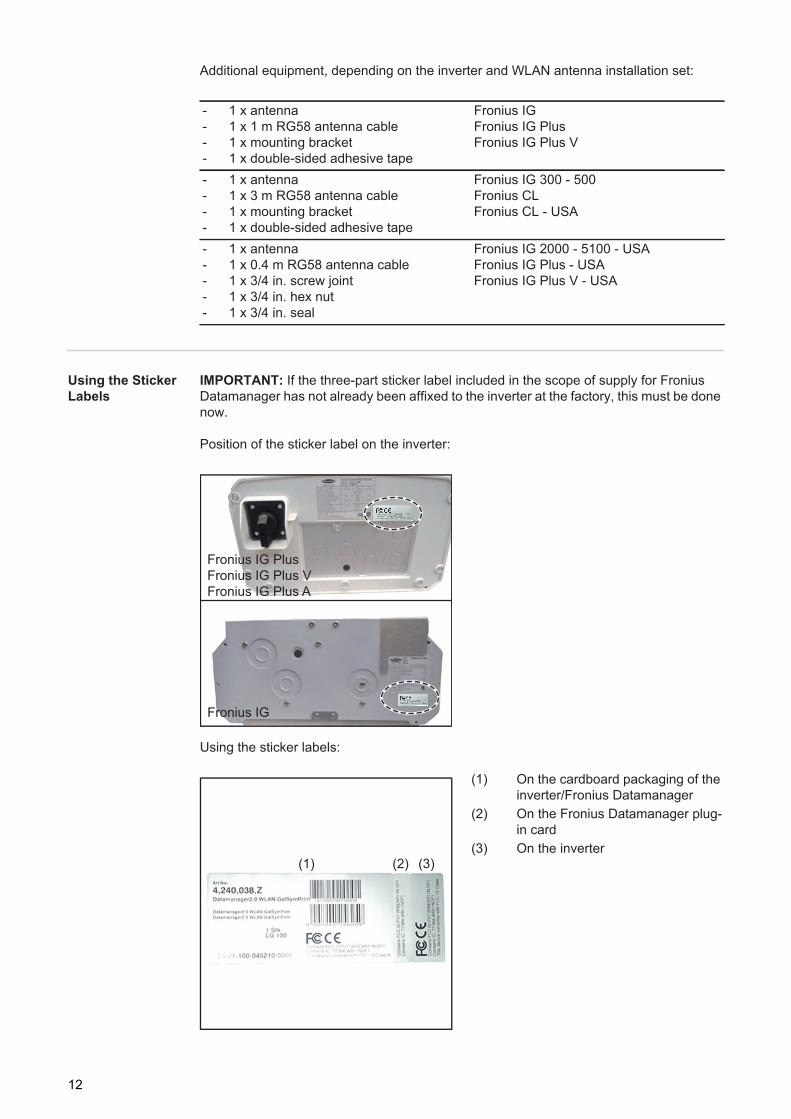
Additional equipment, depending on the inverter and WLAN antenna installation set:
Using the Sticker Labels
IMPORTANT: If the three-part sticker label included in the scope of supply for Fronius Datamanager has not already been affixed to the inverter at the factory, this must be done now.
Position of the sticker label on the inverter:
Using the sticker labels:
(1) On the cardboard packaging of the inverter/Fronius Datamanager
(2) On the Fronius Datamanager plug-in card
(3) On the inverter
- 1 x antenna- 1 x 1 m RG58 antenna cable- 1 x mounting bracket- 1 x double-sided adhesive tape
Fronius IGFronius IG PlusFronius IG Plus V
- 1 x antenna- 1 x 3 m RG58 antenna cable- 1 x mounting bracket- 1 x double-sided adhesive tape
Fronius IG 300 - 500Fronius CLFronius CL - USA
- 1 x antenna- 1 x 0.4 m RG58 antenna cable- 1 x 3/4 in. screw joint- 1 x 3/4 in. hex nut- 1 x 3/4 in. seal
Fronius IG 2000 - 5100 - USAFronius IG Plus - USAFronius IG Plus V - USA
Fronius IG
Fronius IG PlusFronius IG Plus VFronius IG Plus A
(1) (2) (3)
12

EN-U
S
Configuration Ex-amplesLinking inverters with Fronius Datamanager to a PC:
(1) Inverter+
(2) Fronius Datamanager(3) Terminating plug(4) PC/Laptop
Linking inverters with Fronius Datamanager to other inverters, a Fronius Sensor Box, and a PC:
IN
(1)
(2)
(3)
(4)
LAN / WLAN
NOTE! When linking an inverter with Fronius Datamanager to a PC it is neces-sary to insert a terminating plug into the Fronius Datamanager IN connection socket.
(1) Inverter+
(2) Fronius Datamanager(3) PC/Laptop(4) Inverter
+(5) Fronius Com Card
(6) Fronius Sensor Box(7) Inverter
+(8) Fronius Com Card(9) Terminating plug
NOTE! When linking several DATCOM components in a Fronius Datamanager network:Use the data cable to connect the IN connection socket of Fronius Datamanager with the OUT connection socket of the next DATCOM component. A terminating plug must be inserted into the empty IN connection socket of the last DATCOM component.The inverter with the Fronius Datamanager must always be connected either at the start or at the end of the data chain.
IN
IN
INOUT
OUT
OUTIN
(1)(6)
(4) (7)
(2)
(3)
(5) (8)
LAN / WLAN
(9)
13
Calculating the data volume
General When operating the Fronius Datamanager, data is generated and needs to be transmitted online.In order to select a suitable internet connection it is necessary to calculate the data volume.
The following data volume calculation provides an overview of the amount of data gener-ated when operating Fronius Datamanager.
Firmware ver-sions for calculat-ing the data volume
The data volume calculation is based on Fronius Datamanager Firmware versions V 2.3.x-x and lower.
Higher firmware versions can cause a higher data volume due to their increased functional range.
Calculating Data Volumes
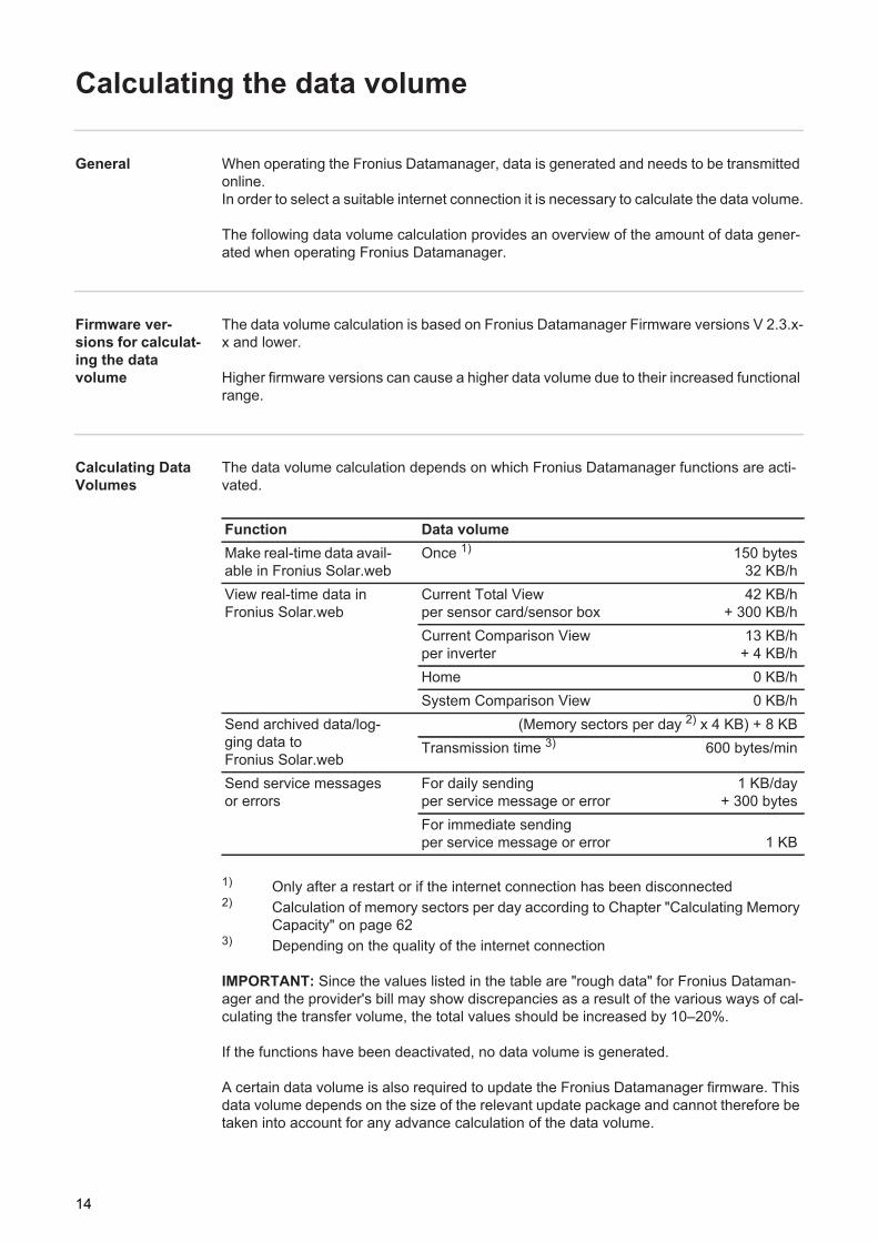
The data volume calculation depends on which Fronius Datamanager functions are acti-vated.
1) Only after a restart or if the internet connection has been disconnected2) Calculation of memory sectors per day according to Chapter "Calculating Memory
Capacity" on page 623) Depending on the quality of the internet connection
IMPORTANT: Since the values listed in the table are "rough data" for Fronius Dataman-ager and the provider's bill may show discrepancies as a result of the various ways of cal-culating the transfer volume, the total values should be increased by 10–20%.
If the functions have been deactivated, no data volume is generated.
A certain data volume is also required to update the Fronius Datamanager firmware. This data volume depends on the size of the relevant update package and cannot therefore be taken into account for any advance calculation of the data volume.
Function Data volumeMake real-time data avail-able in Fronius Solar.web
Once 1) 150 bytes32 KB/h
View real-time data in Fronius Solar.web
Current Total Viewper sensor card/sensor box
42 KB/h + 300 KB/h
Current Comparison Viewper inverter
13 KB/h + 4 KB/h
Home 0 KB/hSystem Comparison View 0 KB/h
Send archived data/log-ging data to Fronius Solar.web
(Memory sectors per day 2) x 4 KB) + 8 KBTransmission time 3) 600 bytes/min
Send service messages or errors
For daily sendingper service message or error
1 KB/day+ 300 bytes
For immediate sendingper service message or error 1 KB
14

EN-U
S
IMPORTANT: Fronius recommends a flat rate in order to avoid unforeseeable data vol-umes.
Calculation exam-ples
Example 1 - Home System
1 inverter;No Fronius Sensor Card/Box;Fronius Datamanager has a 24-hour internet connection;
+ 0.15 KB
+ 32 KB/h x 24 h = 768 KB
Archived data is sent to Fronius So-lar.web;30 minutes transfer time;inverters operate 14 h/day;15 minutes storage interval;(This results in 1 memory sector per day in accordance with the section "Calculating memory capacity")
+ 0.6 KB/min x 30 min = 18 KB
+ (1 memory sector/day x 4 KB) + 8 KB = 12KB
Real-time data is viewed over a 15-minute period every day
+ 42 KB/h x 0.25 h = 10.5 KB
1 service message sent each day to con-firm average error rate
+ 1 service message x 1 KB = 1 KB
Subtotal without safety 0.15 KB768.00 KB18.00 KB12.00 KB10.50 KB1.00 KB
809.65 KB
A 10% safety factor is added to the calcu-lation
809.65 KB + 10%
Final result 890.615 KB/day
15

Example 2 - Large System
100 inverters;10 sensor cards/sensor boxes;Fronius Datamanager has a 24-hour internet connection;
+ 0.15 KB
+ 32 KB/h x 24 h = 768 KB
Archived data is sent to Fronius So-lar.web;120 minutes transfer time;inverters operate 14 h/day;5 minutes storage interval;(This results in 173 memory sectors per day in accordance with the section "Calcu-lating memory capacity")
+ 0.6 KB/min x 120 min = 72 KB
+ (173 memory sectors/day x 4 KB)+ 8 KB
= 700 KB
The current Total View and the current Comparison View are viewed over a two-hour period every day
+ 42 KB/h x 2 h+ 300 KB/h x 10 x 2 h
+ (13 KB/h + 100 x 4 KB/h) x 2 h= 6910 KB
50 service messages sent each day to confirm average error rate
+ 50 service messages x 1 KB = 50 KB
Subtotal without safety 0.15 KB768.00 KB72.00 KB
700.00 KB6910.00 KB
50.00 KB8,500.15 KB
A 10% safety factor is added to the calcu-lation
8,500.15 KB + 10%
Final result 9,350.165 KB/day(approx. 9.35 MB/day)
16
EN-U
S
General information for the network administrator
Requirements
If Fronius Datamanager is being integrated into an existing network, the Fronius Datama-nager address must be adapted to the network.
Example: Network address range = 192.168.1.x, subnet mask = 255.255.255.0
- An IP address between 192.168.1.1 and 192.168.1.254 must be assigned to Fronius Datamanager.
- The IP address selected may not be already assigned in the network.- The subnet mask must correspond to the existing network (e.g. 255.255.255.0).
If Fronius Datamanager will be sending service messages and/or data to Fronius So-lar.web, then a gateway address and a DNS server address must also be entered. Fronius Datamanager uses the gateway address to access the Internet. The IP address of the DSL router can be used as a gateway address, for example.
IMPORTANT!- Fronius Datamanager may not have the same IP address as the PC/laptop!- Fronius Datamanager cannot connect to the Internet spontaneously. A router must be
used for a DSL connection to the Internet.
If you are using the WLAN network connection, the Fronius Datamanager must be equipped with a WLAN function and a WLAN antenna suitable for the inverter.
General Firewall Settings
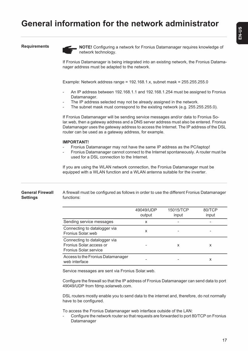
A firewall must be configured as follows in order to use the different Fronius Datamanager functions:
Service messages are sent via Fronius Solar.web.
Configure the firewall so that the IP address of Fronius Datamanager can send data to port 49049/UDP from fdmp.solarweb.com.
DSL routers mostly enable you to send data to the internet and, therefore, do not normally have to be configured.
To access the Fronius Datamanager web interface outside of the LAN:- Configure the network router so that requests are forwarded to port 80/TCP on Fronius
Datamanager
NOTE! Configuring a network for Fronius Datamanager requires knowledge of network technology.
49049/UDP output
15015/TCPinput
80/TCPinput
Sending service messages x - -Connecting to datalogger via Fronius Solar.web x - -
Connecting to datalogger via Fronius Solar.access or Fronius Solar.service
- x x
Access to the Fronius Datamanager web interface - - x
17

Sending service messages via a DSL Internet con-nection
Normally, no additional router configuration is required for a regular DSL Internet connec-tion for accessing 'Fronius Solar.web' and/or sending service messages, because connec-tions from the LAN to the Internet are open.
Using Fronius So-lar.web and send-ing service messages
However, an internet connection is required to use Fronius Solar.web and send service messages.
Fronius Datamanager cannot connect to the Internet spontaneously. A router must be used for a DSL connection to the Internet.
18
EN-U
S
Controls, connections and indicators
Safety
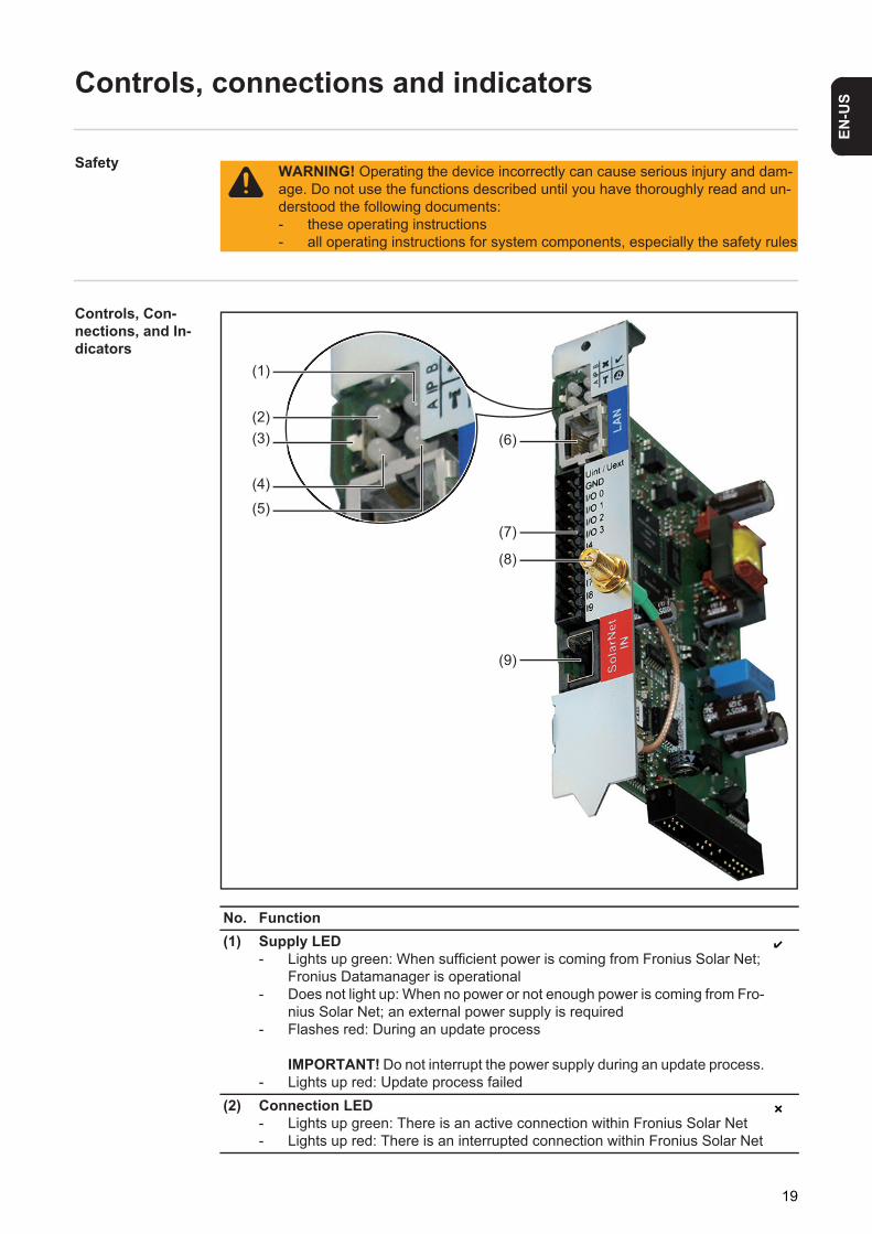
Controls, Con-nections, and In-dicators
WARNING! Operating the device incorrectly can cause serious injury and dam-age. Do not use the functions described until you have thoroughly read and un-derstood the following documents:- these operating instructions- all operating instructions for system components, especially the safety rules
No. Function(1) Supply LED
- Lights up green: When sufficient power is coming from Fronius Solar Net; Fronius Datamanager is operational
- Does not light up: When no power or not enough power is coming from Fro-nius Solar Net; an external power supply is required
- Flashes red: During an update process
IMPORTANT! Do not interrupt the power supply during an update process.- Lights up red: Update process failed
(2) Connection LED- Lights up green: There is an active connection within Fronius Solar Net- Lights up red: There is an interrupted connection within Fronius Solar Net
(1)
(2)(3)
(4)
(5)
(6)
(7)
(8)
(9)
19

(3) IP switchFor changing the IP address:A Default IP address "169.254.0.180"
Fronius Datamanager uses the fixed IP address 169.254.0.180;the fixed IP address is used for a direct connection to a PC via LAN without first having to pre-configure the PC
B Assigned IP addressFronius Datamanager operates using an assigned IP address (factory setting 192.168.1.180); The IP address can be set on the Fronius Datamanager web interface.
(4) WLAN LED- Flashes green: Fronius Datamanager is in service mode (IP switch on the
Fronius Datamanager plug-in card is in position A)- Lights up green: When there is an existing network connection- Lights up red: When there is no existing network connection- Does not light up: Plug-in card without WLAN
(5) Solar Web LED connection- Lights up green: There is an existing connection to Fronius Solar.web- Lights up red: When there is no connection to Fronius Solar.web, but one
is required- Does not light up: When no connection to Fronius Solar.web is required
(6) LAN connection socketEthernet interface colored blue for connecting the Ethernet cable
(7) I/OsDigital inputs and outputs
Digital inputs: I/O 0 – I/O 3, I 4 – I 9 voltage level: low = min. 0 V – max. 1.8 V; high = min. 3 V – max. 30 V input currents: dependent on input voltage; input resistance = 46 kOhm
Digital outputs: I/O 0 – I/O 3 Switching capacity when supplied by the Datamanager plug-in card: 3.2 W, 10.7 V in total for all 4 digital outputs
Switching capacity when supplied by an external power supply with min. 10.7 – max. 24 V DC, connected to Uint / Uext and GND: 1 A, 10.7–24 V DC (depend-ing on the external power supply) per digital output
The connection to the I/Os is made via the supplied mating connector.(8) WiFi Antenna Socket (only for versions with WiFi)
used for connecting the WiFi antenna or the WiFi antenna extension cable(9) Solar Net IN connection socket
Fronius Solar Net input colored red for connecting other DATCOM components (e.g., inverters, sensor cards, etc.)
No. Function
20

EN-U
S
Schematic Con-nection of I/OsSupply via Datamanager plug-in card:(1) Power supply(2) Current limit
Supply via external power supply:(3) External power supply(4) Load
Uin
t / U
ext
GN
DI/O
0I/O
1I/O
2I/O
3I 4 I 5 I 6 I 7 I 8 I 9
(1)
(4)
Solar Net IN
230 V AC10,7 V DC
(2) 300 mA
+ -10,7 - 24 V DC
(3)
NOTE! When the supply is via an external power supply, the exter-nal power supply must be galvani-cally isolated.
21

22

Installing Fronius Datamanager


EN-U
S
Inserting Fronius Datamanager into an inverter
General Please see the operating instructions for the respective inverter for information regarding plug-in card installation. Please note the safety and warning information in your inverter's operating instructions.
IMPORTANT! Before inserting the Fronius Datamanager plug-in card, remove any exist-ing Fronius Com Card, Fronius Power Control Card, or Fronius Modbus Card!
Safety WARNING! An electric shock can be fatal. Danger from grid voltage and DC volt-age from solar modules.- The connection area should only be opened by a licensed electrician.- The separate power stage set area should only be disconnected from the
connection area after first being disconnected from the grid power.- The separate power stage set area should only be opened by Fronius-trained
service personnel.
Before making any connections, make sure that the AC and DC sides are discon-nected from the inverter, e.g.:- Switch off the AC automatic circuit breaker for the inverter- Cover solar modules
Please observe the 5 safety rules.
WARNING! An electric shock can be fatal. Danger from residual voltage from ca-pacitors. You must wait until the capacitors have discharged.
NOTE! Follow general ESD precautions when handling plug-in cards.
25

Fronius Dataman-ager plug-in posi-tions
The Fronius Datamanager plug-in position is specified for each inverter type:
*) If an ENS plug-in card has been inserted into an ENS slot:Insert Fronius Datamanager in the next slot to the right of the ENS slot.
IMPORTANT!The next slot must remain empty!Do not remove an inserted ENS plug-in card under any circumstances!
Inverter Plug-in positionFronius IG 15 - 60 ENS plug *)
Fronius IG 300 - 500 ENS plug *)
Fronius IG Plus, Fronius IG Plus V
on the far right, unless a ML-MON plug-in card is present
Fronius CL on the far right, unless a ML-MON plug-in card is present
EN
S
Dat
aman
ager
26

EN-U
S
Installing and connecting WLAN antennas
General If the Fronius Datamanager is equipped with WLAN, the WLAN antenna must be installed either inside or outside the inverter, depending on which inverter is being used.
IMPORTANT! Always follow the relevant operating instructions when opening an inverter.Observe the safety guidelines.
Fronius IG, Fro-nius IG Plus, Fro-nius IG Plus V, Fronius CL: In-stalling and Con-necting Antennas
Use the double-sided adhesive tape to fasten the mounting bracket to the out-side of the inverter housing or, if suita-ble for the antenna cable, secure it in a position near the inverter
IMPORTANT! The double-sided adhe-sive tape only reaches its maximum bond strength after 24 hours.
IMPORTANT! The mounting bracket may not be screwed to the inverter housing.It may however be fitted in a nearby po-sition. The relevant screws are not in-cluded in the scope of delivery and must be selected by the installer.
Connect the antenna cable to Fronius DatamanagerRun the antenna cable out through the "DATCOM Opening" on the inverterIf possible, secure the cable with a strain relief deviceClose or seal the "DATCOM Opening" in accordance with the inverter opera-ting instructions
2
1
1
1
20,8 - 1,1 Nm
2
3
4
5
27

Remove the hex nut and washer from the outside thread of the antenna cable
Run the antenna cable through the drill hole on the mounting bracketAttach the lock washer and screw on the hex nutScrew on the antenna
1
2
6
NOTE! To avoid damaging the antenna, only use the hexagonal head to fasten the antenna.
6
1
5
2
34
0,9 Nm
7
8
9
28

EN-U
S
Fronius IG USA, Fronius IG Plus USA, Fronius IG Plus V USA: In-stalling and Con-necting Antennas1 2
1 2
1 2
1
2
11
2
CAUTION! Danger of short circuit caused by loose metal parts from knockouts. Loose metal parts in the inverter may cause short circuits when the inverter is powered up. When removing knockouts, make sure that - no loose metal parts fall into the inverter,- any metal pieces that do fall into the inverter are removed immediately.
1
20.9 Nm8 in-lb
3
119 mm3/4 in.
4
NOTE! In order to ensure leak-tightness, the sealing ring must be fitted to the an-tenna screw joint before inserting the antenna screw joint into the inverter hous-ing.
! !
1
2
5
1
6
29
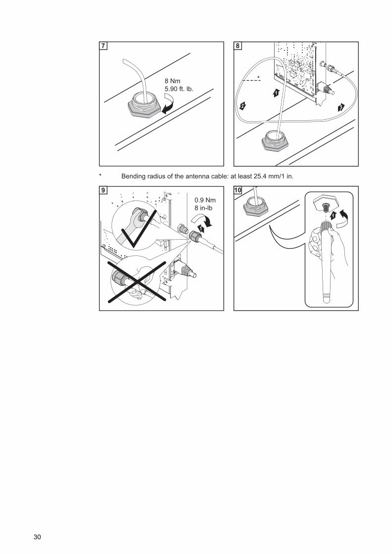
3 4
* Bending radius of the antenna cable: at least 25.4 mm/1 in.1 2
8 Nm5.90 ft. lb.
7
33
1
2
*
8
1
0.9 Nm8 in-lb
9
1
10
30

EN-U
S
Installing Fronius Datamanager in Fronius Solar Net
Installing Invert-ers with Fronius Datamanager in Fronius Solar Net
* Terminating plug, if only one inverter with Fronius Datamanager is linked to a PC** Solar Net Cable, if an inverter with Fronius Datamanager is linked to a PC and oth-
er DATCOM components
Insert and lay the Ethernet cable in the inverter like a data communication cable in ac-cordance with the operating instructions for the inverterInsert the Ethernet cable into the LAN connection socketInsert the Ethernet cable into the PC/laptop or into a suitable network connection sock-etIf only one inverter with Fronius Datamanager is being linked to a PC:Insert the terminating plug into the Solar Net IN connection socket
If other DATCOM components are connected to the network, besides the inverter with Fronius Datamanager:Insert the Solar Net cable into the Solar Net IN connection socket of Fronius Datama-nager.
Connect the other DATCOM components
IMPORTANT! A terminating plug must be inserted into the empty IN connection sock-et of the last DATCOM component.
CAUTION! DATCOM components and/or the PC/laptop may be seriously dam-aged if the Ethernet or Solar Net cables are connected incorrectly to the Fronius Datamanager.- The Ethernet cable should only be inserted into the LAN connection socket
(colored blue).- The Solar Net cable should only be inserted into the Solar Net IN connection
socket (colored red).
DATCOMIN OUT
2
45 IN
LAN
3
1
**
*
LAN
WLAN
1
23
4
5
31

Cabling
Fronius Solar Net clients
Inverters with Fronius Datamanager, Fronius Hybridmanager or Fronius Com Card, DAT-COM components with external housing or other DATCOM components will hereinafter be referred to as Fronius Solar Net clients.
Fronius Solar Net Client Cabling
The data connection for the Fronius Solar Net client is a 1:1 connection using 8-pin data cables and RJ-45 plugs.The overall line length in a Fronius Solar Net ring must not exceed 1000 m.
Requirements for the Solar Net Data Cables
Shielded CAT5 (new) and CAT5e (old) cables compliant with ISO 11801 and EN 50173 must be used for the Fronius Solar Net client cabling. Other cables are not permitted.
IMPORTANT! Do not use ISO/IEC-11801 U/UTP cables!
The shield must be crimped onto a CAT5-compatible shielded plug.
Due to the fact that the wires in Ethernet cables are twisted, you must make sure the twist-ed pairs of wires are assigned correctly for cabling in accordance with TIA/EIA-568B:
Cabling compliant with TIA/EIA-568B
- Make sure that the wires are assigned correctly.- When setting up an independent ground connection (e.g., in patch panels), make sure
that the shield is grounded on one side of the cable only.
Permitted cables:- S/STP- F/STP- S/FTP
- F/FTP- SF/FTP- S/UTP
- F/UTP- U/FTP- U/STP
Fronius Solar Net contact Pair no. Color
1 +12 V 3 white/orange line
2 GND 3 orange/white line or orange
3 TX+ IN, RX+ OUT 2 white/green line
4 RX+ IN, TX+ OUT 1 blue/white line or blue
5 RX- IN, TX- OUT 1 white/blue line
6 TX- IN, RX- OUT 2 green/white line or green
7 GND 4 white/brown line
8 +12 V 4 brown/white line or brown
32

EN-U
S
The following structured cabling standards must generally be observed:- EN 50173-1 for Europe- ISO/IEC 11801:2002 internationally- TIA/EIA 568 for North America
Rules for use of copper cables apply.
Preassembled data cables
The following preassembled data cables are available from Fronius:- CAT5 cable 1 m ... 43,0004,2435- CAT5 cable 20 m ... 43,0004,2434- CAT5 cable 60 m ... 43,0004,2436
The cables listed above are 8-pin, 1:1 LAN network cables, shielded and twisted, including RJ 45 plugs.
IMPORTANT! Data cables are not UV resistant. They should be protected from sunlight when laid outdoors.
33

Installing Fronius Datamanager – Overview
Safety
Starting Up for the First Time
Insert Fronius Datamanager into the inverter
Insert blue Ethernet cable into Fronius Datamanager (LAN connection socket)Insert terminating plug into Fronius Datamanager (Solar Net IN connection socket)Insert blue Ethernet cable into the PC/laptop
Turn off WLAN on PC/laptop (to avoid network conflicts)Adjust network settings for Fronius Datamanager on PC/laptop: "Obtain an IP address automatically (DHCP)" must be activatedSwitch IP switch on Fronius Datamanager to position - A -
Close the inverter and switch it onAfter about 1 minute, open the browser on the PC/laptop and enter the following ad-dress (web server works with Internet Explorer 9 or higher, Chrome or Firefox):http://169.254.0.180
The start page of the Commissioning Wizard appears.
WARNING! Operating the device incorrectly can cause serious injury and dam-age. Do not use the functions described until you have thoroughly read and un-derstood the following documents:- these operating instructions- all operating instructions for system components, especially the safety rules
NOTE! Installing Fronius Datamanager requires knowledge of network technolo-gy.
See section "Inserting Fronius Datamanager into an inverter"
See section "Installing Fronius Datamanager in Fronius Solar Net"
1
234
56
7
89
34
EN-U
S
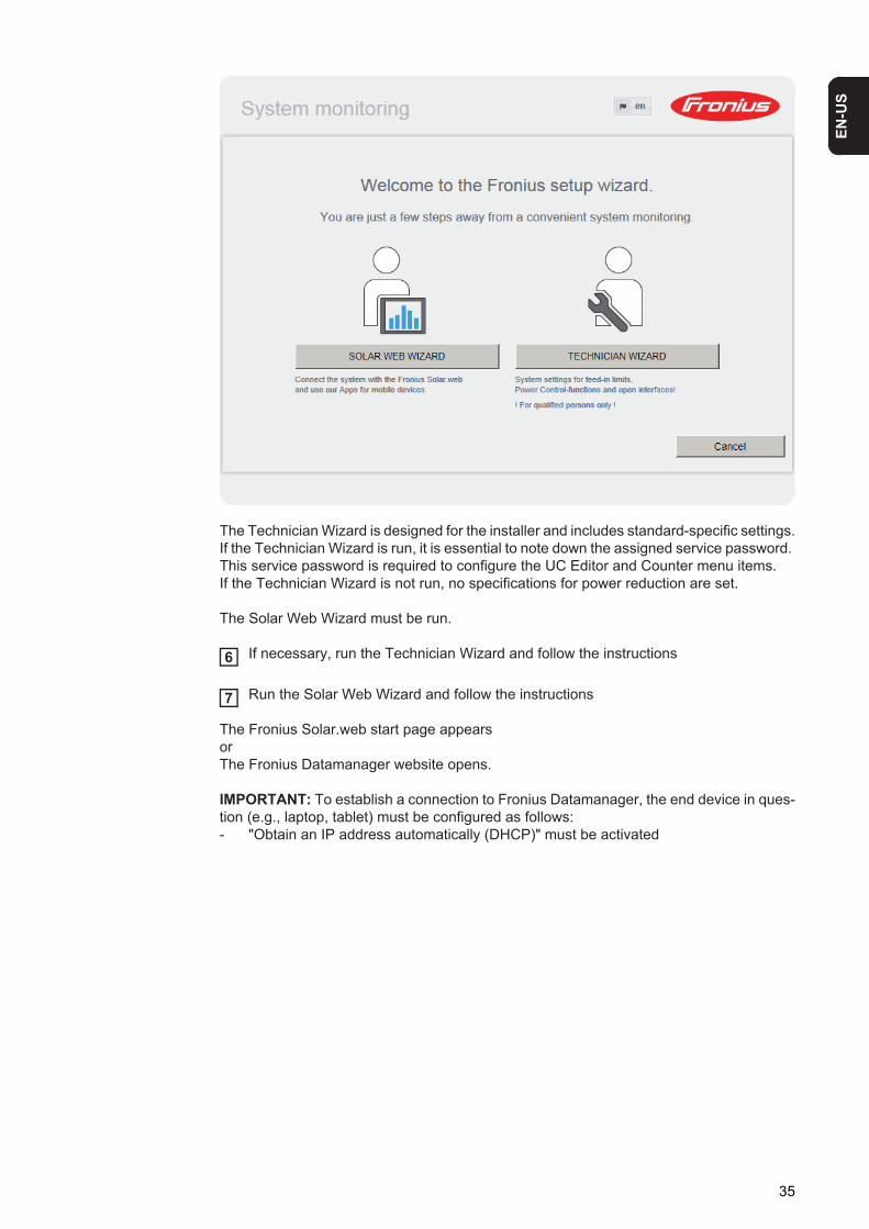
The Technician Wizard is designed for the installer and includes standard-specific settings.If the Technician Wizard is run, it is essential to note down the assigned service password. This service password is required to configure the UC Editor and Counter menu items.If the Technician Wizard is not run, no specifications for power reduction are set.
The Solar Web Wizard must be run.
If necessary, run the Technician Wizard and follow the instructions
Run the Solar Web Wizard and follow the instructions
The Fronius Solar.web start page appears orThe Fronius Datamanager website opens.
IMPORTANT: To establish a connection to Fronius Datamanager, the end device in ques-tion (e.g., laptop, tablet) must be configured as follows:- "Obtain an IP address automatically (DHCP)" must be activated
6
7
35

36

Connect to Fronius Datamanager

EN-U
S
Connecting to Fronius Datamanager via a Web Browser
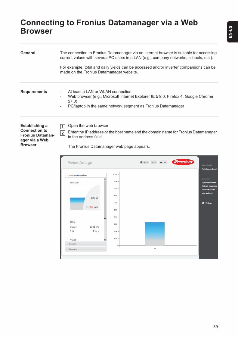
General The connection to Fronius Datamanager via an internet browser is suitable for accessing current values with several PC users in a LAN (e.g., company networks, schools, etc.).
For example, total and daily yields can be accessed and/or inverter comparisons can be made on the Fronius Datamanager website.
Requirements - At least a LAN or WLAN connection- Web browser (e.g., Microsoft Internet Explorer IE ≥ 9.0, Firefox 4, Google Chrome
27.0)- PC/laptop in the same network segment as Fronius Datamanager
Establishing a Connection to Fronius Dataman-ager via a Web Browser
Open the web browserEnter the IP address or the host name and the domain name for Fronius Datamanager in the address field
The Fronius Datamanager web page appears.
12
39

Connecting to Fronius Datamanager via the Internet and Fronius Solar.web
General By connecting to Fronius Datamanager via the Internet and Fronius Solar.web, you can ac-cess archived data and real-time photovoltaic system data online from anywhere in the world.You can also provide other users with guest access so that they can view your photovoltaic system, or you can make a comparison of several systems.
Function over-view
Fronius Datamanager is connected to the Internet (e.g. via a DSL router). Fronius Data-manager regularly logs on to Fronius Solar.web and sends its saved data every day. Fronius Solar.web can actively contact Fronius Datamanager, e.g. to display real-time da-ta.
Requirements - Internet access- Web browser
IMPORTANT! Fronius Datamanager cannot connect itself to the Internet. A router must be used for a DSL connection to the Internet.
- Registration of photovoltaic system with Fronius Solar.web.
- In order to access real-time data in Fronius Solar.web, the "Yes" option must be acti-vated under "Send real-time data to Solar.web" in Fronius Datamanager.
- In order to access archived data in Fronius Solar.web, the "Daily" or "Hourly" option must be activated under "Send archived data to Solar.web" in Fronius Datamanager.
Accessing data from Fronius Datamanager via the Internet and Fronius So-lar.web
To access real-time and archived data from Fronius Datamanager using Fronius So-lar.web:
Start Fronius Solar.web: http://www.solarweb.comFor more information about Fronius Solar.web, see the online help.
1
40

Current Data, Services, and Settings on Fronius Datamanager

EN-U
S
The Fronius Datamanager Website
Fronius Dataman-ager Website – Overview
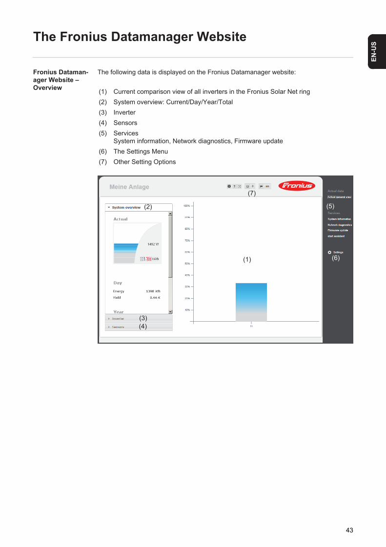
The following data is displayed on the Fronius Datamanager website:
(1) Current comparison view of all inverters in the Fronius Solar Net ring(2) System overview: Current/Day/Year/Total(3) Inverter(4) Sensors(5) Services
System information, Network diagnostics, Firmware update(6) The Settings Menu(7) Other Setting Options
(1)
(2)
(3)(4)
(5)
(6)
(7)
43

The Settings Menu
After clicking on "Settings," the Settings menu is opened on the Fronius Datamanager web page.Fronius Datamanager is configured in the Settings menu.
Other setting op-tions
Other settings options are shown in the top right corner of the Fronius Datamanager web interface:
Menu items in Settings menu
General Adjustment and Viewing of Menu Items
Connect to Fronius DatamanagerClick on "Settings"Click on the desired menu item
The desired menu item is opened.
View menu item or edit accordingly.If there is one, click on the relevant button (e.g, Save, Syn-chronize)
The amended data is accepted.
* Selected menu item** The Counter and UC Editor menu items are protected
by the service password.
*
**
**
123
45
Display notifications
System information:Datalogger ID, software version, hardware version, Solar Net connection, So-lar.web connectionHelp:Fronius Datamanager operating instructions, available in both English and Ger-manLanguage:For setting the language (English or German)
The Fronius Datamanager web interface will appear in the language set in the browser or in the last language selected.Expand contents:The Real-time Data/Settings menu is hidden
44

EN-U
S
Current Data in Fronius Datamanager
Current Compari-son View
Several inverters in the same photovoltaic system can be compared in the current Com-parison View.
The real-time inverter AC power is displayed as a percentage of the power from the solar module connected to the respective inverter (shown in a bar diagram). A bar is displayed for each inverter. The bar color indicates the power range of the inverter:
Blue: the inverter power corresponds to the average power of all inverters.Yellow: the inverter power deviates slightly from the average power of all inverters
(50–90% from the average).Red: the inverter power deviates significantly from the average power of all in-
verters or an error has occurred in the inverter (< 50% from the average).
45
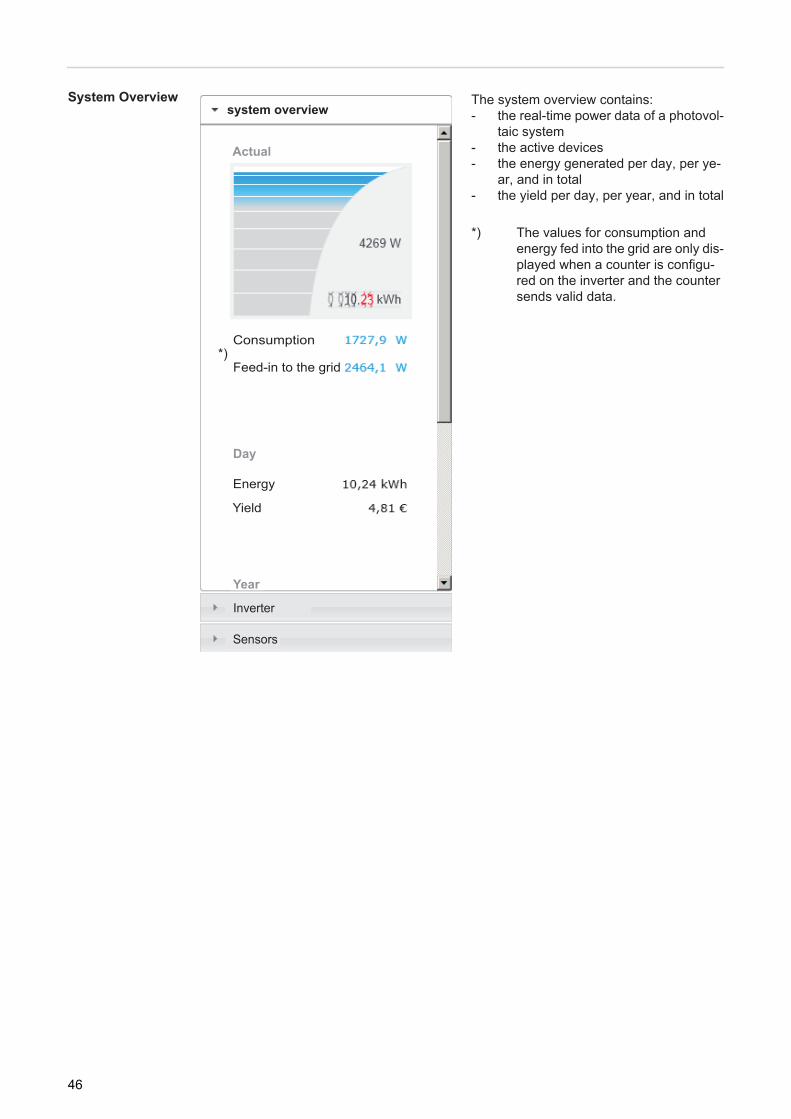
System Overview The system overview contains:- the real-time power data of a photovol-
taic system- the active devices- the energy generated per day, per ye-
ar, and in total- the yield per day, per year, and in total
*) The values for consumption and energy fed into the grid are only dis-played when a counter is configu-red on the inverter and the counter sends valid data.
system overview
Consumption
Feed-in to the grid
Day
Energy
Yield
CO2 saved
Year
Inverter
Sensors
Actual
*)
46

EN-U
S
Inverter/Sensors ViewInverter View
The Inverter View displays all the inverters present in the system.
*) Clicking on an inverter or the corre-sponding bar in the Comparison View displays the inverter's real-time data:
Sensor View
The Sensor View displays all the sensor cards/boxes present in the system.
*)
53
80 kWh12 MWh36 MWh
47

Services – System Information
System Informa-tion
(1) "Datalogger restart" button used to restart Fronius Datamanager
(2) "Reset to factory settings" button (3) Option "All settings except for the network"
is used to reset Fronius Datamanager to factory settings.The network settings and all items protected by the service user (UC Editor, count-er settings, and the service password) are retained.
(4) Option "Settings"is used to reset Fronius Datamanager and the network settings to factory settings.All items protected by the service user (UC Editor, counter settings, and the service password) are retained.
IMPORTANT: When Fronius Datamanager is reset to factory settings, the time and date settings must be checked.
(1) (2)
48

EN-U
S
Services – Network Diagnostics
Network Diagnos-tics
The Services / Network diagnostics option contains functions that are useful for diagnosing and correcting network problems. Ping and traceroute commands can be executed.
The ping command is used to determine whether or not a host is available and how much time a data transfer will take.
Sending a ping command:
Enter a host name or IP address in the "Host:" field (1)Click on "ping" (2)
- Ping command is sent- The resulting data is displayed
A traceroute command is used to determine the intermediate stations via which the data reaches the host.
Sending a traceroute command:
Enter a host name or IP address in the "Host:" field (1)Click on "traceroute" (3)
- Traceroute command is sent- The resulting data is displayed
(1)(2) (3)
12
12
49

Services – Firmware Update
General You can update the Fronius Datamanager firmware under Services / Firmware Update. A firmware update can be performed via LAN or web.
(1) Automatic update search(2) "Check now" button (to search for updates manually)(3) Use proxy server for Web update
(3a) Field to enter the proxy server(3b) Field to enter the port(3c) Field to enter the user(3d) Field to enter the password
(4) Carry out update via web(5) Carry out update via LAN
(5a) Field to enter the IP address
(6) "Run update" button to launch update process
(7) "Apply/Save" button(8) "Cancel/Discard entries" button
(2)(1)(3)
(4)(5)
(6)
(7) (8)
(3)(3a)(3b)(3c)(3d)
(5)
(5a)
50

EN-U
S
Automatic Update SearchIMPORTANT: An internet connection is required for the automatic update search.
When the "Automatic update search" option (1) is activated, Fronius Datamanager will au-tomatically search for updates once a day. If new updates are available, a message is dis-played under the other setting options for the Fronius Datamanager website.
Manual Update Search
When the "Automatic update search" function is deactivated, there will be no automatic search for updates.
To search manually for updates, use the "check now" button (2)
Firmware update via web
Open the Fronius Datamanager web page via a web browserOpen "Firmware update" under "Service"Select "Update via web"Click on the "Run update" button
The confirmation prompt for the update appears:
Click on the "Yes" button
The update starts. The update progress is displayed as a bar and a percentage.
(1)
1
(2)
1234
5
51

Once the update has been carried out successfully, click on the "Apply/Save" button
If the connection to the server fails:- Deactivate the firewall for the duration of the update- Retry the update
IMPORTANT: If a proxy server is used to connect to the internet:- The "Use proxy server for Web update" option must be activated- The required data must be entered
Firmware Update via LAN
Establish LAN connection between PC/laptop and Fronius DatamanagerDownload the current firmware from the Fronius homepageRun the downloaded update file on the PC/laptop
This will start a web server from which Fronius Datamanager will download the re-quired files.
Open the Fronius Datamanager web page via a web browserOpen settings/firmware updateSelect "Update via LAN"Enter the IP address of the PC/laptopClick on the "Run update" button
The confirmation prompt for the update appears:
Click on the "Yes" button
The update starts. The update progress is displayed as a bar and a percentage.
Once the update has been carried out successfully, click on the "Apply/Save" button
The update is complete when the "Supply LED" lights up green.
6
123
45678
9
10
52

EN-U
S
If the connection to the server fails:- Deactivate the firewall for the duration of the update- Retry the update
53

Services – Opening Wizards
Opening Wizards The Commissioning Wizard can be opened again and run under "Open Wizards."
54

EN-U
S
Settings – General
General
You can enter the charge rate per kWh (1), the currency (2) and the expenses per kWh (3) to calculate the yield under "Feed-in payment." The yield is shown in the current Total View.
The date (4), hour (5), and minutes (6) can be entered under "System time." Click "Synchronize" (7) to adapt the displayed time in the entry fields of the Fronius Data-manager web page to the time set on the computer operating system.Click the "Apply/Save" button (10) to apply the time.
The region (8) and location (9) for the time zone can be set under "Time zone settings."
(10) "Apply/Save" button(11) "Cancel/Discard entries" button
* Fields marked with * are mandatory fields.
(1) (2)
(3)
(4) (5) (6)
(7)
(11)
(8) (9)
(10)
55

Settings – Passwords
General Access to Fronius Datamanager is regulated by assigning passwords.3 different password types are available:- the administrator password- the service password- the user password
Passwords
(1) Administrator password, user name = admin
The administrator password set during commissioning assigns the user read and write (configuration) access to Fronius Datamanager. The user can then open the "Settings" menu item and define any settings as desired, with the exception of the UC Editor and counter settings.
When an administrator password is set, the user must enter the user name and password in Fronius Datamanager to open the "Settings" menu item.
(2) Service password, user name = service
The service password is usually assigned in the Commissioning Wizard by the ser-vice technician or system installer and provides access to system-specific param-eters. The service password is required to define counter settings and settings in the UC Editor. If no service password has been assigned, the Counter and UC Ed-itor menu items cannot be accessed.
(3) After activating the selection field, the user password is displayed, user name = us-er.
(1)
(2)
(3)
(4)
(4)
56

EN-U
S
An assigned user password only gives the user read access to Fronius Dataman-ager. The user cannot open the "Settings" menu item.
When assigning a user password, users must enter their username and password every time they connect to Fronius Datamanager.
(4) "Apply/Save" button
(3)(4)
57

Settings – Inverter
Views – Inverter
The data for the Comparison View is defined in "Inverter."
(1) Field for assigning a system name *(2) Number of the inverter in Fronius Solar Net(3) If the selection field is chosen, the inverter is displayed in the Comparison View(4) Display of device type(5) Field for assigning a device name *(6) Field for entering the solar module power in W *(7) "Apply/Save" button(8) "Cancel/Discard entries" button
* Fields marked with * are mandatory fields.
Symo left side 5000
(2) (3) (4) (5) (6)
(7) (8)(1)
58

EN-U
S
Settings – Fronius Sensor Cards
Sensor Cards
A specific channel name can be assigned to each sensor value of a Fronius Sensor Card/Box in "Sensor Cards" (e.g., wind speed).
(1) Sensor Card selection(2) Displayed measuring channel(3) Fields for assigning the channel name(4) "Apply/Save" button(5) "Cancel/Discard entries" button
(3)
(4) (5)
(1)(2)
59

Settings – Fronius Solar.web
Solar.web The Solar.web menu item can be used to make a direct connection between Fronius Data-manager and Fronius Solar.web.
Datalogging settings
(1) Selection of query cycle for the inverter:Data queries every 5/10/15/20/30 minutes
(2) Selection of query cycle for Fronius Sensor Cards:Data queries every 5/10/15/20/30 minutes
(3) "Delete log data" buttonAfter clicking the "Delete log data" link, a security prompt appears to confirm the deletion of the log data.
(4) Selection of whether current data is sent to Fronius Solar.web
Send archived data to Fronius Solar.web
(5) Never
(6) DailyAfter the selection field is activated the setting options are displayed:
(6a) Field for entering the time (hour)(6b) Fields for selecting the weekdays
(7) HourlyAfter the selection field is activated the setting options are displayed:
(1)(2)
(3)
(4)
(5) (6) (7)
(10)
(8)
(9)
(6)(6a)
(6b)
never daily hourly
aton Monday Tuesday Wednesday Thursday Friday Satturday Sunday
60

EN-U
S
(7a) Fields for selecting the time (hour)
(8) "Register Solar.web" buttonClicking this link opens the Fronius Solar.web start page; data relevant for Fronius Solar.web is automatically sent as well.
(9) "Apply/Save" button(10) "Cancel/Discard entries" button
(7)
(7a)
61
Calculating memory capacity
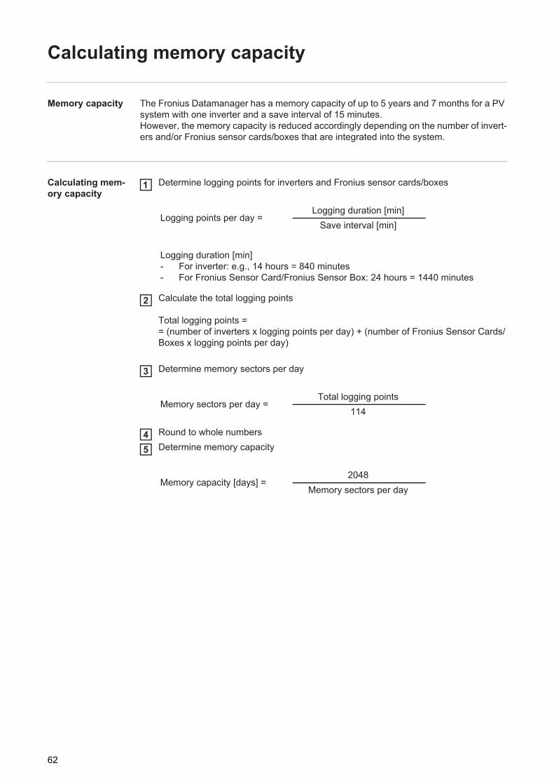
Memory capacity The Fronius Datamanager has a memory capacity of up to 5 years and 7 months for a PV system with one inverter and a save interval of 15 minutes.However, the memory capacity is reduced accordingly depending on the number of invert-ers and/or Fronius sensor cards/boxes that are integrated into the system.
Calculating mem-ory capacity
Determine logging points for inverters and Fronius sensor cards/boxes
Calculate the total logging points
Total logging points == (number of inverters x logging points per day) + (number of Fronius Sensor Cards/Boxes x logging points per day)
Determine memory sectors per day
Round to whole numbersDetermine memory capacity
Logging points per day =Logging duration [min]
Save interval [min]
Logging duration [min]- For inverter: e.g., 14 hours = 840 minutes- For Fronius Sensor Card/Fronius Sensor Box: 24 hours = 1440 minutes
Memory sectors per day =Total logging points
114
Memory capacity [days] =2048
Memory sectors per day
1
2
3
45
62

EN-U
S
Calculation exam-ple2 inverters, logging duration = 14 hours (840 minutes)1 Fronius Sensor Card, logging duration = 24 hours (1440 minutes)
Save interval = 15 minutes
1. Logging points per day:
2. Total logging points:
3. Memory sectors per day:
4. Rounded:
5. Memory capacity [days]:
Inverter logging points =840 min
= 5615 min
Sensor Card logging points = 1440 min
= 9615 min
Total logging points = (2 x 56) + (1 x 96) = 208
(2 x 56) ... 2 inverters, (1 x 96) ... 1 Sensor Card
Memory sectors =208
= 1,825114
1,825 2
Memory capacity = 2048
= 1024 days (= 2 years, 9 months, 18 days)2
Memory capacity [days] =2048
Memory sectors per day
63

Settings – Service Messages
General Service messages, inverter errors, the Fronius String Control, etc., are sent to Fronius Datamanager and saved. The "Service messages" selection option is used to define how service messages are communicated. They can be communicated via:- E-mail- SMS
Service messages can be analyzed further using Fronius Solar.web.
Service Messag-es
(1) Message to e-mail recipientActivate to send service messages to one or more e-mail addresses
(2) Field for up to a max. of 10 e-mail addressesSeparate e-mail addresses with ";"
(3) Selection field to determine whether the service message will be sent immediately via e-mail or at a specific timeIf "daily" is selected, the selection options for the time (hour) are also displayed.
(4) "Send test e-mail" buttonSending a test e-mail may take several minutes.
(5) Message to SMS recipientActivate to send service messages as an SMS to a telephone number
(6) Field to enter the country codee.g.: +43 = country code for Austria
(7) Field to enter area code
(8) Field to enter the telephone number
(9) Field for sending daily
(10) Selection field for the time (hour) at which a service message is to be sent via SMS
(1) (2)(3) (4)
(5) (6) (7) (8)(9) (11)(10)
(14)(13)
(12)
64

EN-U
S
(11) "Send test SMS" buttonSending a test SMS may take several minutes.
(12) Selection field for the language in which the service message will be sent
(13) "Apply/Save" button
(14) "Cancel/Discard entries" button
65

Settings – Network
General The "Network" menu item is used to determine the type of internet connection (LAN or WLAN).
IMPORTANT! If the IP address is obtained statically, a gateway and a DNS server must be entered for the selected network interface.
Network
(1)
(2)
(3) (4)
(5)(6)(7)
(10)
(8)(9)
(22)(21)
(18)(17)(16)
(13)
(14)
(12)
(11)
(15)
Home Network
Local HotSpot
StonisNetwork
Add WLAN
66

EN-U
S
(1) Internet connection via LAN
(2) Internet connection via WLAN
LAN
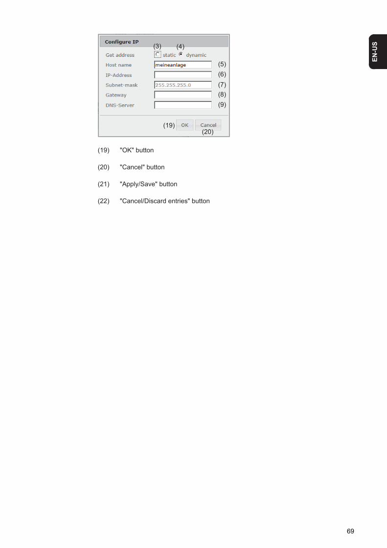
(3) Obtain IP address staticallyThe user enters a fixed IP address for Fronius Datamanager and also manually sets the subnet mask, gateway address, and DNS server address (from the pro-vider).
(4) Obtain IP address dynamicallyFronius Datamanager obtains its IP address from a DHCP server (DHCP = dynam-ic host configuration protocol).The DHCP server must be configured so that Fronius Datamanager is always as-signed the same IP address. You will then always know the IP address at which Fronius Datamanager can be found.If the DHCP server supports the "DNS dynamic updates" function, a name can be entered for Fronius Datamanager in the "Host name" field. The connection to Fro-nius Datamanager can then be established using the name instead of the IP ad-dress. For example: Host name = sample_system, Domain name = fronius.com. The Fronius Datamanager can be reached via the address "sample_system.fro-nius.com".
(5) Field for entering a host name for dynamically obtained IP address
(6) Field for entering the IP address for static IP address
(7) Field for entering the subnet mask for static IP address
(8) Field for entering the gateway for static IP address
(9) Field for entering the DNS server for static IP address
WLAN
(10) Display of detected WLAN networks
(11) "Refresh" buttonUsed to search again for available WLAN networks
(12) Display of signal qualityOne bar = low signal strengthThree bars = high signal strength
(13) Network statusOpen/secured/saved (after pressing the "Setup" button (16))
(14) Display of encryptionWPA / WPA2 / WEP
(15) Add WLANUsed to display hidden networksClicking this option opens the "WLAN connection" window
67

(15a) Name of hidden WLAN network(15b) Selection field for encrypting the hidden WLAN network(15c) Field for entering the password for the hidden WLAN network(15d) Selection field for whether the password is displayed(15e) "Save" button(15f) "Cancel" button
(16) "Setup" buttonUsed to save a selected WLAN network;Clicking this option opens the "WLAN connection" window
(16a) Name of selected WLAN network(16b) Signal strength of selected WLAN network(16c) Encryption of selected WLAN network(16d) Field for entering the password for the WLAN network(16e) Selection field for whether the password is displayed(16f) "Save" button(16 g) "Cancel" button
(17) "Remove" buttonUsed to delete a saved WLAN network
(18) "Configure IP" buttonClicking this option opens the "Configure IP" window
(15b)(15c)
(15d)
(15e)
Network:
Security:
Enter password:
Show password:
Connection
Save Cancel
(15a)
(15f)
(16a)(16b)(16c)
(16d)(16e)
(16f)(16g)
Network:
Signal quality:
Security:
Enter password:
Show password:
Connection
good
Save Cancel
68
EN-U
S
(19) "OK" button
(20) "Cancel" button
(21) "Apply/Save" button
(22) "Cancel/Discard entries" button
(3) (4)
(5)(6)(7)
(20)(19)
(8)(9)
69
Settings – Energy Manager
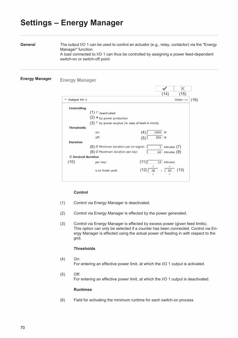
General The output I/O 1 can be used to control an actuator (e.g., relay, contactor) via the "Energy Manager" function. A load connected to I/O 1 can thus be controlled by assigning a power feed-dependent switch-on or switch-off point.
Energy Manager
Control
(1) Control via Energy Manager is deactivated.
(2) Control via Energy Manager is effected by the power generated.
(3) Control via Energy Manager is effected by excess power (given feed limits).This option can only be selected if a counter has been connected. Control via En-ergy Manager is effected using the actual power of feeding in with respect to the grid.
Thresholds
(4) On:For entering an effective power limit, at which the I/O 1 output is activated.
(5) Off:For entering an effective power limit, at which the I/O 1 output is deactivated.
Runtimes
(6) Field for activating the minimum runtime for each switch-on process
(1)(2)(3)
(4)(5)
(6) (7)(8) (9)
(11)(10)
(12) (13)
(14) (15)(16)
70

EN-U
S
(7) Field for entering a minimum time for which the output I/O 1 is to be activated for each switch-on process
(8) Field for activating the maximum runtime per day
(9) Field for entering a maximum time for which the output I/O 1 is to be activated in total per day (several switch-on processes are included).
Target runtime
(10) Field for activating a target runtime
(11) Field for entering a minimum time for which the output I/O 1 is to be activated in total per day (several switch-on processes are included)
(12) Field for selecting the hour, if the target runtime is to be achieved by a certain time
(13) Field for selecting the minute, if the target runtime is to be achieved by a certain time
(14) "Apply/Save" button
(15) "Cancel/Discard entries" button
(16) Status displayIf the mouse pointer is moved over the status, the reason for the current status is displayed.
If "by excess power" is selected under "Control", additional selection fields for Feed (3a) and Reference (3b) are displayed under "Thresholds":
(3)
(4)(5)
(3a)(3b) Consumption
71

Settings – Push Service
Push Service This function can be used to export current and log data in different formats or with different protocols to an external server.
(1) "Apply/Save" button
(2) "Cancel/Discard entries" button
(3) "Add" buttonClicking this button adds a new push service job. The new job is saved by clicking the "Apply/Save" button (1).
(4) StatusDisplays the current status of the push service job in question
(5) Displayed name of push service job
(6) Area for entering general data: Name (name of push service job)File formatProtocol type (FTP upload/HTTP POST)IntervalActivation status
(7) Area for entering the target data:Server portUpload file nameLogin (user/password)
(1) (2)(3)
(4)(5)
(6)
(7)
(8)
(9)
72

EN-U
S
(8) Area for entering the proxy data:Server portUserPassword
(9) "Delete" buttonClicking this button deletes the selected push service job
Further Informa-tion about the Push Service Function
Further information about the push service function can be found in the following operating instructions:
http://www.fronius.com/QR-link/4204102152
42.0410.2152 Fronius Push Service
73

Modbus Settings
General From your web browser, you can use the Fronius Datamanager web page to apply the Modbus connection settings which cannot be accessed via the Modbus protocol.
Additional Infor-mation on the Modbus Function
For additional information on the Modbus function, please see the following operating in-structions:
Data Output via Modbus
http://www.fronius.com/QR-link/4204102049
42,0410,2049 Fronius Datamanager Modbus connection
Data Output via ModbusActivation of the Modbus service and selection of the transmission protocol.If the Modbus service is activated, additional entry fields are available.
(1) offNo data output via Modbus
(2) tcpData output via Modbus TCP
(2a) Modbus portNumber of the TCP port which must be used for Modbus communication.
(1) (2)
(3)
(4) (5)
(2)
(2a)(2b)
(2c) (2d)
(2e)(2f)
74

EN-U
S
(2b) String Control address offsetOffset value used to assign addresses to Fronius String Controls via Modbus.For further details, see the section entitled "Modbus Device ID for Fronius String Controls."
Sunspec model typeUsed to select the data type of data models for inverters.
(2c) floatDisplay as floating-point numbersSunSpec Inverter model I111, I112 or I113
(2d) int+SFDisplay as integers with scaling factorsSunSpec Inverter model I101, I102 or I103
IMPORTANT! Since the different models have different numbers on registers, the register addresses of all the subsequent models also change when the data type is changed.
(2e) Demo modeThe demo mode is used to implement or validate a Modbus master. It enables you to read inverter and String Control data without actually connecting or activat-ing a device. The same data is always sent back for all the registers.
(2f) Inverter control via ModbusIf this option is activated, the inverter can be controlled via Modbus.The "Limit Control" selection field is displayed.Inverter control includes the following functions:- On/off- Power reduction- Setting a constant power factor (cos phi)- Setting a constant reactive power
(3) Control prioritiesUsed to specify which service is given priority by the inverter control unit.
1 = highest priority, 3 = lowest priority
The control priorities can only be changed in the UC EDITOR menu item.
(4) "Apply/Save" button
(5) "Cancel/Discard entries" button
75
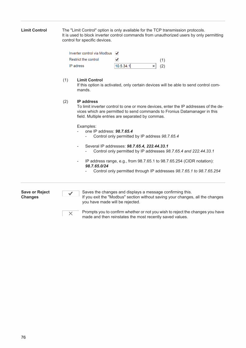
Limit Control The "Limit Control" option is only available for the TCP transmission protocols.It is used to block inverter control commands from unauthorized users by only permitting control for specific devices.
Save or Reject Changes
Saves the changes and displays a message confirming this.If you exit the "Modbus" section without saving your changes, all the changes you have made will be rejected.
Prompts you to confirm whether or not you wish to reject the changes you have made and then reinstates the most recently saved values.
(1) Limit ControlIf this option is activated, only certain devices will be able to send control com-mands.
(2) IP addressTo limit inverter control to one or more devices, enter the IP addresses of the de-vices which are permitted to send commands to Fronius Datamanager in this field. Multiple entries are separated by commas.
Examples:- one IP address: 98.7.65.4
- Control only permitted by IP address 98.7.65.4
- Several IP addresses: 98.7.65.4, 222.44.33.1- Control only permitted by IP addresses 98.7.65.4 and 222.44.33.1
- IP address range, e.g., from 98.7.65.1 to 98.7.65.254 (CIDR notation): 98.7.65.0/24- Control only permitted through IP addresses 98.7.65.1 to 98.7.65.254
(1)(2)
76

EN-U
S
Settings – Counter
General IMPORTANT! Settings in the "Counter" menu item may only be entered by staff trained to do so!
The service password must be entered for the "Counter" menu item.
Three-phase or one-phase Fronius Smart Meters may be used. In both cases, selection is made via the "Fronius Smart Meter" item. Fronius Datamanager automatically detects the counter type.
Counter
(1) Field for selecting a counter:- None selected- S0 inverter (for Fronius Galvo, Fronius Symo, Fronius Primo, and Fronius Eco inverters only)
(2) Link to counter circuit diagrams
(3) "Apply/Save" button
(4) "Cancel/Discard entries" button
(1)
(2)
(3) (4)
77

S0 Inverter
(1a) Counter position at feed-in pointThe power of feeding in and energy are measured. The consumption is determined using these values and the system data. An S0 counter must be configured at this position in order to count the fed-in ener-gy.
IMPORTANT! If you are using an S0 counter at the feed-in point, the counter data will not be displayed on Fronius Solar.web. This option is only provided for dynamic power reduction.The consumption values can be detected to a limited extent when feeding into the grid.
(1b) Counter position in consumption branchThe power consumed and energy are measured directly. The power of feeding in and energy are determined using these values and the system data.An S0 counter must be configured at this position in order to count the energy con-sumed.
(1c) Field for entering the impulses per kWh
A counter for recording self-consumption per S0 can be connected directly to the inverter (for Fronius Galvo, Fronius Symo, Fronius Primo, and Fronius Eco only).
IMPORTANT! An S0 counter is connected to the switchable multifunctional current inter-face of the inverter. Connecting an S0 counter to the inverter may require an inverter firm-ware update.
(1)
(2)
(1a) (1b)
(1c)
(1a)
(1b)
78

EN-U
S
Requirements for the S0 counter:- Must meet standard IEC 62053-31 Class B- Max. voltage: 15 V DC- Max. current when ON: 15 mA- Min. current when ON: 2 mA- Max. current when OFF: 0.15 mA
Recommended max. impulse rate of S0 counter:
PV power kWp [kW] Max. impulse rate per kWp30 100020 200010 5000 ≤ 5.5 10,000
Pin 1Pin 2
Pin 1
Pin 2 S0 +
S0 -
79

Settings – UC Editor
General In the "UC Editor" menu item, settings relevant to a utility company are made.An effective power limit in % and/or a power factor limit can be set.
IMPORTANT! Settings in the "UC Editor" menu item may only be made by staff trained to do so!
The service password must be entered for the "UC Editor" menu item.
UC Editor – Rip-ple Control Signal Receiver
UC Editor – Factory setting with 100%, 60%, 30%, and 0% effective power.The settings can be changed at any time.
(1) Activating the rule
(2) Input pattern (assignment of individual I/Os)1 click = white2 clicks = blue3 clicks = gray
(3) First activate effective power, then enter the desired effective power as a %
(1) (2)(3) (4) (5) (6) (7)
(10)
(8)
(9)
(12)(11)
80

EN-U
S
(4) First activate power factor cos phi, then enter the desired power factor and select "ind" or "cap"
ind = inductivecap = capacitive
(5) UC Output (feedback output)When the rule is activated, the I/O 0 output will be activated (e.g., for operating a signal device)
(6) Excluded invertersEnter the numbers of inverters here that are to be excluded from control. Separate multiple inverters with commas.
(7) Delete/Add a Rule+ = add a new rule- = delete selected rule
(8) Legend for use of colors
(9) Click "Import" buttonto import rules in *.fpc format
The function of the "Import" button depends on the browser used, e.g., Firefox and Google Chrome support the function.
(10) Click "Export" buttonto save the rules separately in *.fpc format
(11) "Apply/Save" button
(12) "Cancel/Discard entries" button
Connection Ex-ample
(1) Ripple control signal receiver with 3 relays for effective power limitation(2) Ripple control signal receiver with 3 relays for power factor limitation(3) I/Os on Fronius Datamanager(4) Loads (e.g., signal light, signal relay)
NOTE! The print function of the web browser can be used to save the UC Editor settings as a PDF or print them out (e.g., as a commissioning report).
81

The ripple control signal receiver and the Fronius Datamanager plug are connected to one another using a 4-pin cable in accordance with the connection diagram. For distances of greater than 10 m between Fronius Datamanager and the ripple control signal receiver, a shielded cable is recommended.
Settings on the UC Editor:
UC Editor – Dy-namic Power Re-duction
UCs or utility companies can prescribe feed-in limits for an inverter (e.g., max. 70% of the kWp or max. 5 kW). Dynamic power reduction takes into account self-consumption in the household before the power of an inverter is reduced:- An individual limit can be set.- A counter for determining self-consumption per S0 can be connected directly to the
inverter (for Fronius Galvo, Fronius Symo, Fronius Primo, and Fronius Eco only).
Uint / UextGNDI/O 0I/O 1I/O 2I/O 3I4I5I6I7I8I9
60 %
30 %
0 %
(1)
(2)
(3)
(4)
0,95
0,90
0,85
(1)
(2)
82

EN-U
S
Power limitOption to define the maximum output power of the photovoltaic system.
(1) No limitThe photovoltaic system converts all available PV energy and feeds it into the grid.
(2) Dynamic power reduction limit for the entire systemThe entire photovoltaic system is limited to a fixed power limit.
(3) Field for entering the total DC system power in WpThis value is used as a control reference and also in case of errors (e.g., counter failure).
(4) Field for entering the max. power in W or %
If no counter has been selected in the "Counter" menu item:Max. power generated for the entire system
If S0 inverter has been selected in the "Counter" menu item:Max. energy fed into the grid
(5) Selection field % or W
(6) "Apply/Save" button
(7) "Cancel/Discard entries" button
(1) (2)
(3)
(6) (7)
(4) (5)
83

UC Editor – Con-trol Priorities
1 = highest priority, 3 = lowest priority
(1) Used to set control priorities for the ripple control signal receiver
(2) Used to set control priorities for dynamic power reduction
(3) Used to set control priorities for control via Modbus
(4) "Apply/Save" button
(5) "Cancel/Discard entries" button
(1)(2)(3)
(4) (5)
84

Appendix

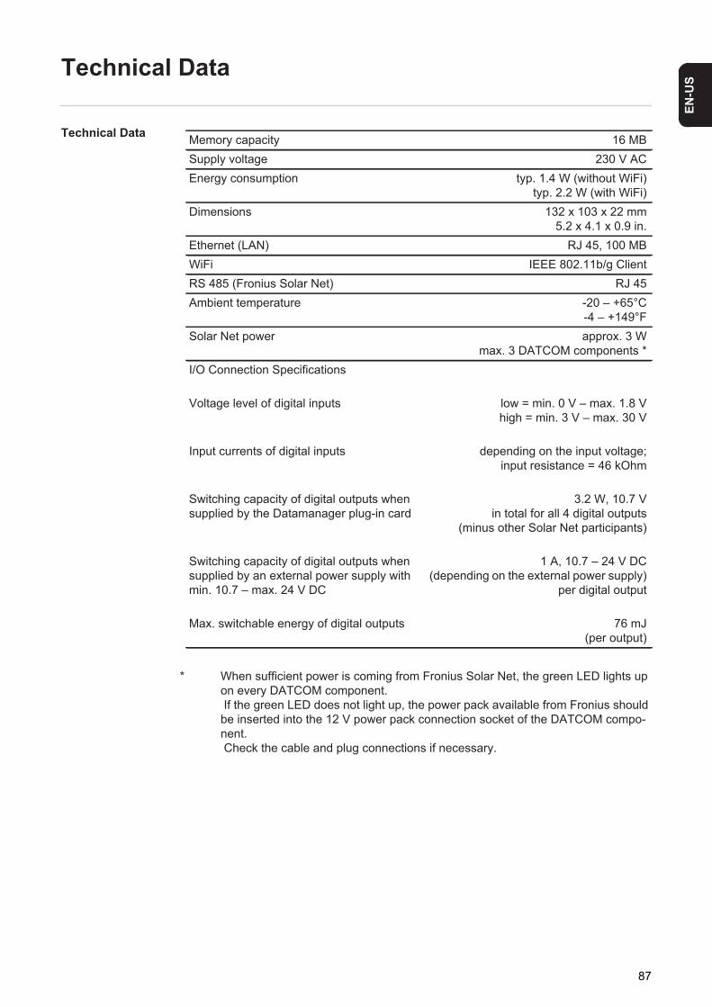
EN-U
S
Technical Data
Technical Data
* When sufficient power is coming from Fronius Solar Net, the green LED lights up on every DATCOM component. If the green LED does not light up, the power pack available from Fronius should be inserted into the 12 V power pack connection socket of the DATCOM compo-nent. Check the cable and plug connections if necessary.
Memory capacity 16 MBSupply voltage 230 V ACEnergy consumption typ. 1.4 W (without WiFi)
typ. 2.2 W (with WiFi)Dimensions 132 x 103 x 22 mm
5.2 x 4.1 x 0.9 in.Ethernet (LAN) RJ 45, 100 MBWiFi IEEE 802.11b/g ClientRS 485 (Fronius Solar Net) RJ 45Ambient temperature -20 – +65°C
-4 – +149°FSolar Net power approx. 3 W
max. 3 DATCOM components *I/O Connection Specifications
Voltage level of digital inputs low = min. 0 V – max. 1.8 V high = min. 3 V – max. 30 V
Input currents of digital inputs depending on the input voltage; input resistance = 46 kOhm
Switching capacity of digital outputs when supplied by the Datamanager plug-in card
3.2 W, 10.7 Vin total for all 4 digital outputs
(minus other Solar Net participants)
Switching capacity of digital outputs when supplied by an external power supply with min. 10.7 – max. 24 V DC
1 A, 10.7 – 24 V DC (depending on the external power supply)
per digital output
Max. switchable energy of digital outputs 76 mJ (per output)
87

Fronius Worldwide - www.fronius.com/addresses
Under http://www.fronius.com/addresses you will find all addresses of our sales branches and partner firms!
Fronius International GmbH4600 Wels, Froniusplatz 1, AustriaE-Mail: [email protected]://www.fronius.com
Fronius USA LLC Solar Electronics Division6797 Fronius Drive, Portage, IN 46368E-Mail: [email protected]://www.fronius-usa.com