operating instructions fronius primo 208-240: symbol
TRANSCRIPT

/ Perfect Charging / Perfect Welding / Solar Energy
42,0426,0197,EA 014-29052017
Fronius Primo 208-240:Symbol Explanations and Choosing the Location Notes on Installation and Connection
Operating Instructions
Inverter for grid-connected photo-voltaic systemsEN
-US

2

EN-U
S
Contents
Symbol Explanations ................................................................................................................................. 5Explanation of Safety Instructions......................................................................................................... 5Explanation of Symbols – Selecting a Location .................................................................................... 5Symbol Explanations – Installation Position ......................................................................................... 7
Choosing the Location ............................................................................................................................... 9Intended Use......................................................................................................................................... 9Selecting a Location – General Information for Fronius Primo 3.8–8.2 ................................................ 9Selecting a Location – General Information for Fronius Primo 10.0–15.0 ............................................ 10
Installation information ............................................................................................................................... 11Auswahl von Dübel und Schrauben...................................................................................................... 11Screw Recommendation....................................................................................................................... 11Attaching the Wall Bracket.................................................................................................................... 11Installing the Inverter on a Mast............................................................................................................ 12
Notes on the Knockouts............................................................................................................................. 13General ................................................................................................................................................. 13Knock or drill out knockouts .................................................................................................................. 13
Suitable Grids ............................................................................................................................................ 15Suitable Grids ....................................................................................................................................... 15
Notes on connection area .......................................................................................................................... 16Permitted cables ................................................................................................................................... 16Connecting Aluminum Cables............................................................................................................... 16
Notes on grid connection ........................................................................................................................... 18Monitoring the Grid ............................................................................................................................... 18AC Connection...................................................................................................................................... 18Maximum AC fuse protection................................................................................................................ 19Additional external AC and/or DC disconnect....................................................................................... 19
Notes on DC Connection ........................................................................................................................... 20General Information about Solar Modules ............................................................................................ 20Inverter DC Connection ........................................................................................................................ 20Multi MPP Tracker Inverter – Fronius Primo 3.0–8.2............................................................................ 20Multi MPP Tracker Inverter – Fronius Primo 10.0–15.0........................................................................ 22
Notes on Laying Data Communication Cables .......................................................................................... 23Laying Data Communication Cables..................................................................................................... 23
Notes on Clipping the Inverter into the Wall Bracket ................................................................................. 24Clipping the Inverter onto the Wall Bracket........................................................................................... 24
Notes on Anti-theft device.......................................................................................................................... 25Anti-Theft Device .................................................................................................................................. 25
Notes on Software Updates ....................................................................................................................... 27Notes on Software Updates .................................................................................................................. 27
USB Stick as a Data Logger and for Updating Inverter Software .............................................................. 28USB stick as a data logger.................................................................................................................... 28Data on the USB stick........................................................................................................................... 28Data Quantity and Memory Capacity .................................................................................................... 29Buffer Memory ...................................................................................................................................... 29Suitable USB Sticks .............................................................................................................................. 30USB Stick for Updating Inverter Software............................................................................................. 30Removing the USB Stick....................................................................................................................... 31
Notes on Maintenance ............................................................................................................................... 32Maintenance ......................................................................................................................................... 32Cleaning................................................................................................................................................ 32
Serial Number Sticker for Customer Use................................................................................................... 33Serial Number Sticker for Customer Use.............................................................................................. 33
3

4
EN-U
S
Symbol Explanations
Explanation of Safety Instruc-tions
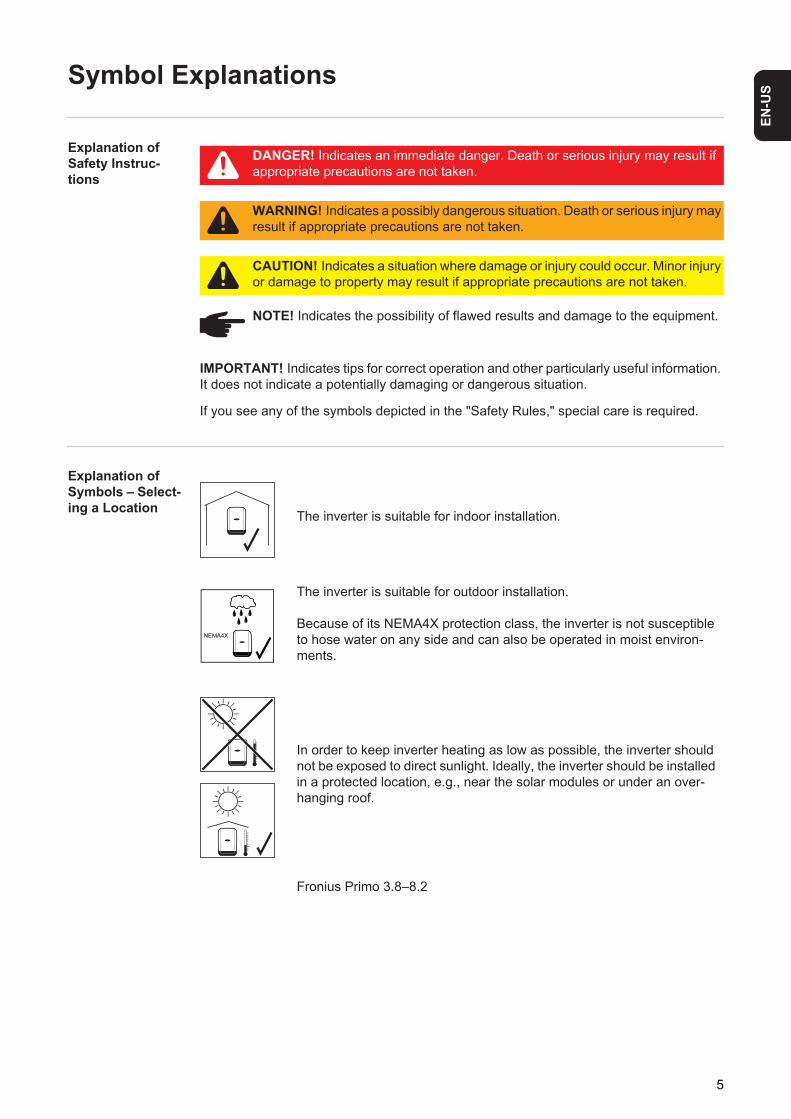
If you see any of the symbols depicted in the "Safety Rules," special care is required.
Explanation of Symbols – Select-ing a Location
DANGER! Indicates an immediate danger. Death or serious injury may result if appropriate precautions are not taken.
WARNING! Indicates a possibly dangerous situation. Death or serious injury may result if appropriate precautions are not taken.
CAUTION! Indicates a situation where damage or injury could occur. Minor injury or damage to property may result if appropriate precautions are not taken.
NOTE! Indicates the possibility of flawed results and damage to the equipment.
IMPORTANT! Indicates tips for correct operation and other particularly useful information. It does not indicate a potentially damaging or dangerous situation.
The inverter is suitable for indoor installation.
The inverter is suitable for outdoor installation.
Because of its NEMA4X protection class, the inverter is not susceptible to hose water on any side and can also be operated in moist environ-ments.
In order to keep inverter heating as low as possible, the inverter should not be exposed to direct sunlight. Ideally, the inverter should be installed in a protected location, e.g., near the solar modules or under an over-hanging roof.
Fronius Primo 3.8–8.2
5
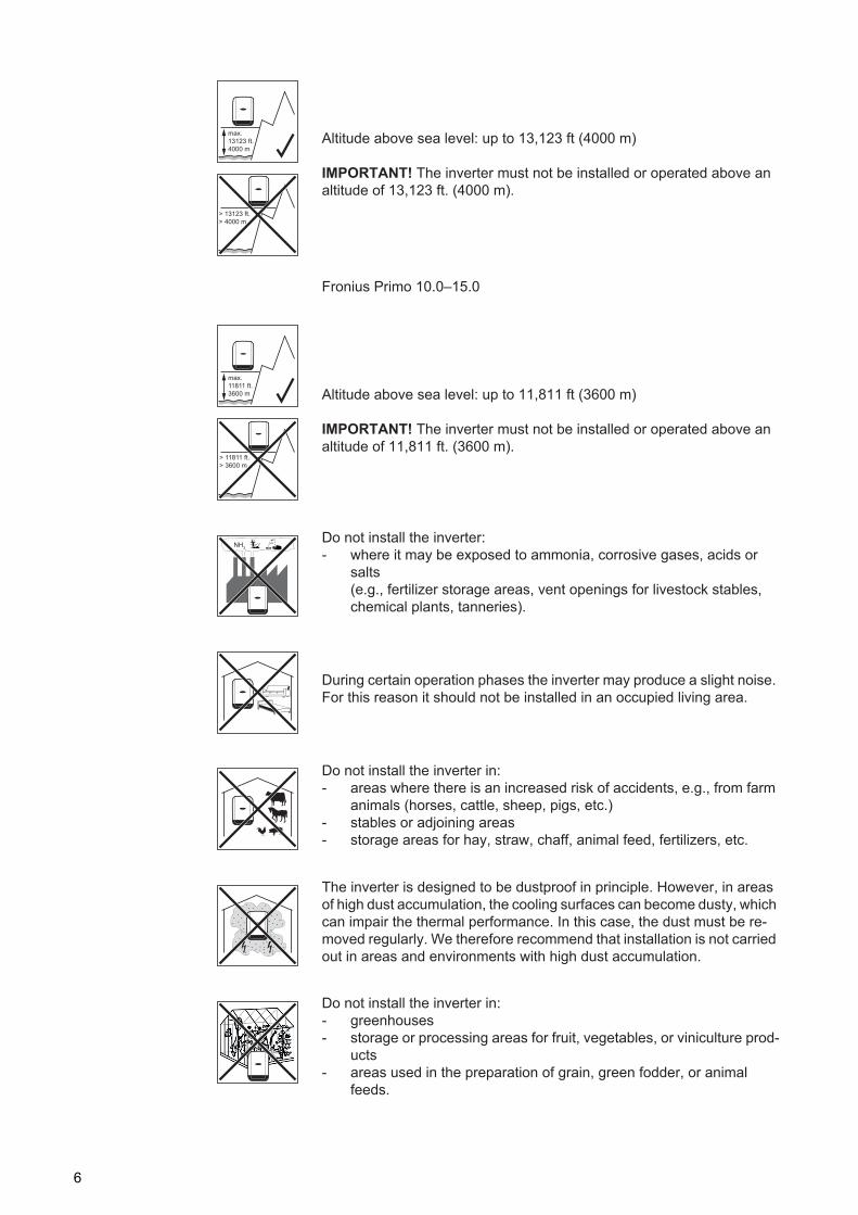
Altitude above sea level: up to 13,123 ft (4000 m)
IMPORTANT! The inverter must not be installed or operated above an altitude of 13,123 ft. (4000 m).
Fronius Primo 10.0–15.0
Altitude above sea level: up to 11,811 ft (3600 m)
IMPORTANT! The inverter must not be installed or operated above an altitude of 11,811 ft. (3600 m).
Do not install the inverter: - where it may be exposed to ammonia, corrosive gases, acids or
salts(e.g., fertilizer storage areas, vent openings for livestock stables, chemical plants, tanneries).
During certain operation phases the inverter may produce a slight noise. For this reason it should not be installed in an occupied living area.
Do not install the inverter in:- areas where there is an increased risk of accidents, e.g., from farm
animals (horses, cattle, sheep, pigs, etc.) - stables or adjoining areas - storage areas for hay, straw, chaff, animal feed, fertilizers, etc.
The inverter is designed to be dustproof in principle. However, in areas of high dust accumulation, the cooling surfaces can become dusty, which can impair the thermal performance. In this case, the dust must be re-moved regularly. We therefore recommend that installation is not carried out in areas and environments with high dust accumulation.
Do not install the inverter in:- greenhouses- storage or processing areas for fruit, vegetables, or viniculture prod-
ucts - areas used in the preparation of grain, green fodder, or animal
feeds.
max.
13123 ft.
4000 m
> 13123 ft.
> 4000 m
max.
11811 ft.
3600 m
> 11811 ft.
> 3600 m
NH3
6
EN-U
S
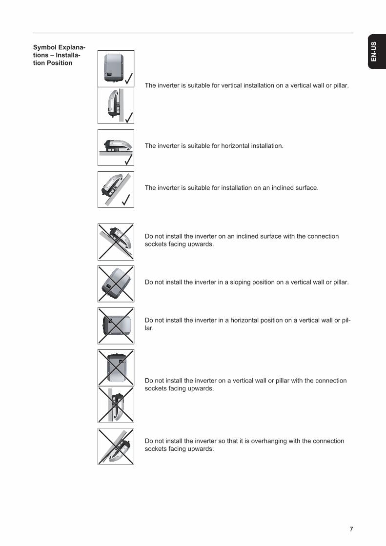
Symbol Explana-tions – Installa-tion PositionThe inverter is suitable for vertical installation on a vertical wall or pillar.
The inverter is suitable for horizontal installation.
The inverter is suitable for installation on an inclined surface.
Do not install the inverter on an inclined surface with the connection sockets facing upwards.
Do not install the inverter in a sloping position on a vertical wall or pillar.
Do not install the inverter in a horizontal position on a vertical wall or pil-lar.
Do not install the inverter on a vertical wall or pillar with the connection sockets facing upwards.
Do not install the inverter so that it is overhanging with the connection sockets facing upwards.
7

Do not install the inverter so that it is overhanging with the connection sockets facing downwards.
Do not install the inverter on the ceiling.
8
EN-U
S
Choosing the Location
Intended Use The inverter is designed exclusively to be connected and used with nongrounded solar modules. The solar modules cannot be grounded at either the positive or negative pole.
The solar inverter is designed exclusively to convert direct current from solar modules into alternating current and feed this power into the public grid. The following are deemed not to be in conformity with its intended purpose:- utilization for any other purpose, or in any other manner- alterations to the inverter that are not expressly recommended by Fronius- installation of components that are not expressly recommended or sold by Fronius.
The manufacturer is not responsible for any damage resulting from improper use. All warranty claims are considered void in such cases.
Proper use also means- carefully reading and obeying all the instructions and safety and danger notices in the
operating instructions- carrying out all the specified inspection and servicing work- installation as per operating instructions.
When configuring the photovoltaic system, make sure that all photovoltaic system compo-nents are operating completely within their permitted operating range.
All measures recommended by the solar module manufacturer for maintaining solar mod-ule properties must be followed.
Utility company regulations regarding grid power feed must be followed.
Selecting a Loca-tion – General In-formation for Fronius Primo 3.8–8.2
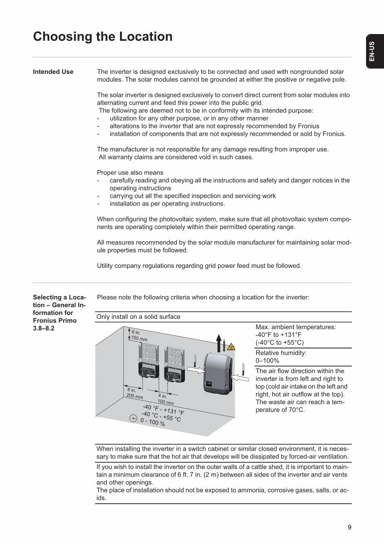
Please note the following criteria when choosing a location for the inverter:
Only install on a solid surfaceMax. ambient temperatures: -40°F to +131°F(-40°C to +55°C)Relative humidity: 0–100%The air flow direction within the inverter is from left and right to top (cold air intake on the left and right, hot air outflow at the top).The waste air can reach a tem-perature of 70°C.
When installing the inverter in a switch cabinet or similar closed environment, it is neces-sary to make sure that the hot air that develops will be dissipated by forced-air ventilation.If you wish to install the inverter on the outer walls of a cattle shed, it is important to main-tain a minimum clearance of 6 ft. 7 in. (2 m) between all sides of the inverter and air vents and other openings.The place of installation should not be exposed to ammonia, corrosive gases, salts, or ac-ids.
8 in.200 mm 4 in.
100 mm
6 in.150 mm
-40 °F - +131 °F-40 °C - +55 °C0 - 100 %
9
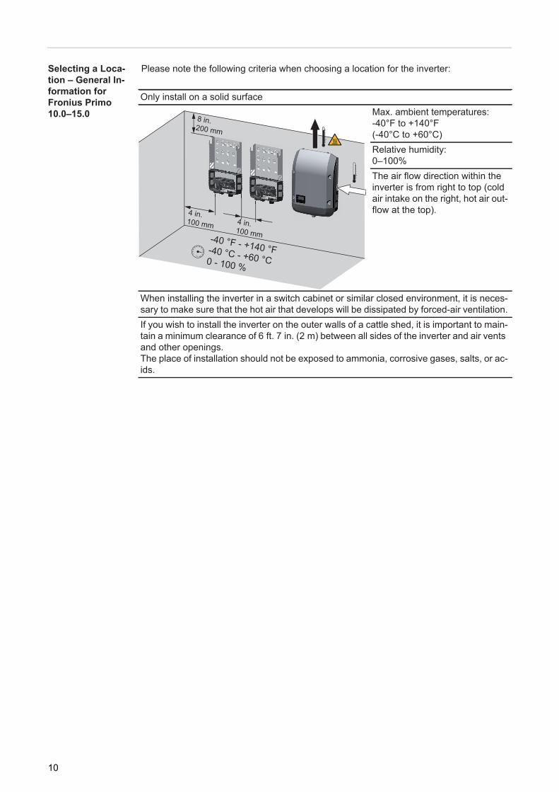
Selecting a Loca-tion – General In-formation for Fronius Primo 10.0–15.0
Please note the following criteria when choosing a location for the inverter:
Only install on a solid surfaceMax. ambient temperatures: -40°F to +140°F(-40°C to +60°C)Relative humidity: 0–100%The air flow direction within the inverter is from right to top (cold air intake on the right, hot air out-flow at the top).
When installing the inverter in a switch cabinet or similar closed environment, it is neces-sary to make sure that the hot air that develops will be dissipated by forced-air ventilation.If you wish to install the inverter on the outer walls of a cattle shed, it is important to main-tain a minimum clearance of 6 ft. 7 in. (2 m) between all sides of the inverter and air vents and other openings.The place of installation should not be exposed to ammonia, corrosive gases, salts, or ac-ids.
4 in.100 mm 4 in.
100 mm
8 in.200 mm
-40 °F - +140 °F-40 °C - +60 °C0 - 100 %
10
EN-U
S
Installation information
Auswahl von Dü-bel und Schrau-ben
Screw Recom-mendation
To install the inverter, the manufacturer recommends using steel or aluminum screws with a diameter of 0.2–0.3 in. (6–8 mm).
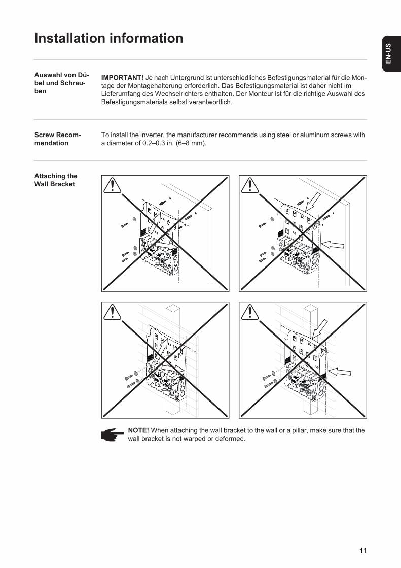
Attaching the Wall Bracket
IMPORTANT! Je nach Untergrund ist unterschiedliches Befestigungsmaterial für die Mon-tage der Montagehalterung erforderlich. Das Befestigungsmaterial ist daher nicht im Lieferumfang des Wechselrichters enthalten. Der Monteur ist für die richtige Auswahl des Befestigungsmaterials selbst verantwortlich.
NOTE! When attaching the wall bracket to the wall or a pillar, make sure that the wall bracket is not warped or deformed.
11

Installing the In-verter on a Mast
Example of a mast mounting kit
For installation of the inverter on a mast or beam, Fronius recommends using the "Po-le clamp" (order no. SZ 2584.000) mast mounting kit from Rittal GmbH. The kit can be used to mount the inverter on round or rectangular masts with the follo-wing diameters: from 40 to 190 mm (round)
from 50 to 150 mm (rectangular)
Fronius Primo 208-240
Installation Help?
12
EN-U
S
Notes on the Knockouts
General The wall bracket contains several knockouts of different sizes. When knocked out, the openings are used for the inputs of various wires.
IMPORTANT! The knockouts on the rear of the wall bracket are made of metal.
Knock or drill out knockouts
IMPORTANT! The side knockouts and the knockouts on the underside of the wall bracket may be knocked out using a hammer or screwdriver, or drilled out using a step drill.The knockouts at the back may only be drilled out using a step drill.
1/2 in. for data communication cable (DATCOM)
for Fronius Primo 3.8-8.2:3/4 in. for AC and DC cables
for Fronius 10.0-15.0:3/4 in. - 1 1/4 in.
for AC and DC cables
* A grounding electrode terminal may be required depending on local regula-tions.The cable for the ground electrode terminal can be fed through the designat-ed opening on the underside of the wall bracket.
CAUTION! Danger of short circuit from loose metal parts from knockouts. Loose metal parts in the inverter may cause short circuits when the inverter is powered up. When removing knockouts, make sure that - no loose metal parts fall into the connection area of the inverter,- any metal pieces that do fall into the connection area are removed immedi-
ately.
Use suitable eye protection when knocking/drilling out the knockouts.
Only knock out knockouts using a hammer or screwdriver from the in-side outwards.
Only use suitable step drills to drill out the knockouts.Do not use spiral drills for drilling out!
Only drill out knockouts using a step drill from the outside inwards.
When drilling out using a step drill, ensure that the DC disconnector and the AC/DC connection block are not damaged.
13

When drilling out the knockouts at the back, place the wall bracket on an even surface with the back upwards so that shavings and pieces of metal can fall out of the wall bracket.
Attach appropriate conduits to all knocked/drilled out knockouts.In the event of installation outside, only use watertight conduits and conduit fittings.Conduits and conduit fittings are not included with the inverter.
*
14
EN-U
S
Suitable Grids
Suitable Grids Inverters can be operated on the following grids:- 208 V Delta - Corner Grounded, without neutral conductor- 208 V Delta: 120 V WYE, with neutral conductor- 220 V Delta - Corner Grounded, without neutral conductor- 220 V Delta: 127 V WYE, with neutral conductor- 240 V Delta - Corner Grounded, without neutral conductor- 240 V: 120 V WYE, with neutral conductor- 240 V: 120 V split phase, with neutral conductor
- 50 Hz (220 V Delta - Corner Grounded, 50 Hz, without neutral conductor)- 50 HN (220 V Delta: 127 V WYE, 50 Hz, with neutral conductor)
15
Notes on connection area
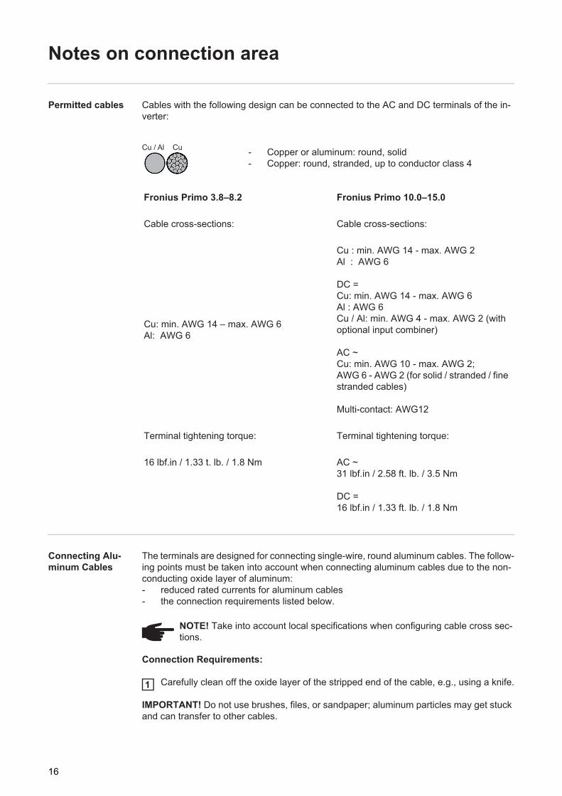
Permitted cables Cables with the following design can be connected to the AC and DC terminals of the in-verter:
Connecting Alu-minum Cables
The terminals are designed for connecting single-wire, round aluminum cables. The follow-ing points must be taken into account when connecting aluminum cables due to the non-conducting oxide layer of aluminum:- reduced rated currents for aluminum cables - the connection requirements listed below.
Connection Requirements:
Carefully clean off the oxide layer of the stripped end of the cable, e.g., using a knife.
IMPORTANT! Do not use brushes, files, or sandpaper; aluminum particles may get stuck and can transfer to other cables.
- Copper or aluminum: round, solid- Copper: round, stranded, up to conductor class 4
Fronius Primo 3.8–8.2 Fronius Primo 10.0–15.0
Cable cross-sections: Cable cross-sections:
Cu: min. AWG 14 – max. AWG 6Al: AWG 6
Cu : min. AWG 14 - max. AWG 2Al : AWG 6
DC =Cu: min. AWG 14 - max. AWG 6 Al : AWG 6 Cu / Al: min. AWG 4 - max. AWG 2 (with optional input combiner)
AC ~Cu: min. AWG 10 - max. AWG 2;AWG 6 - AWG 2 (for solid / stranded / fine stranded cables)
Multi-contact: AWG12
Terminal tightening torque: Terminal tightening torque:
16 lbf.in / 1.33 t. lb. / 1.8 Nm AC ~31 lbf.in / 2.58 ft. lb. / 3.5 Nm
DC =16 lbf.in / 1.33 ft. lb. / 1.8 Nm
Cu / Al Cu
NOTE! Take into account local specifications when configuring cable cross sec-tions.
1
16

EN-U
S
After removing the oxide layer of the cable end, rub in a neutral grease, e.g., acid-free and alkali-free Vaseline.Then immediately connect it to the terminal.
Repeat the steps above whenever the cable is disconnected and then reconnected.
2
3
17
Notes on grid connection
Monitoring the Grid
AC Connection
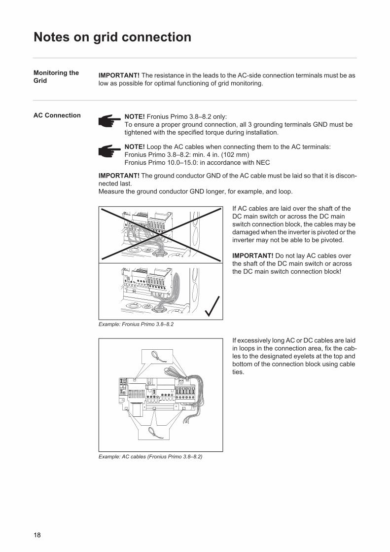
IMPORTANT! The ground conductor GND of the AC cable must be laid so that it is discon-nected last.Measure the ground conductor GND longer, for example, and loop.
Example: Fronius Primo 3.8–8.2
If AC cables are laid over the shaft of the DC main switch or across the DC main switch connection block, the cables may be damaged when the inverter is pivoted or the inverter may not be able to be pivoted.
IMPORTANT! Do not lay AC cables over the shaft of the DC main switch or across the DC main switch connection block!
Example: AC cables (Fronius Primo 3.8–8.2)
If excessively long AC or DC cables are laid in loops in the connection area, fix the cab-les to the designated eyelets at the top and bottom of the connection block using cable ties.
IMPORTANT! The resistance in the leads to the AC-side connection terminals must be as low as possible for optimal functioning of grid monitoring.
NOTE! Fronius Primo 3.8–8.2 only:To ensure a proper ground connection, all 3 grounding terminals GND must be tightened with the specified torque during installation.
NOTE! Loop the AC cables when connecting them to the AC terminals:Fronius Primo 3.8–8.2: min. 4 in. (102 mm)Fronius Primo 10.0–15.0: in accordance with NEC
18
EN-U
S
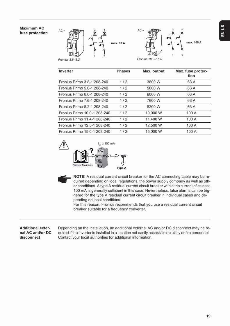
Maximum AC fuse protectionFronius 3.8–8.2 Fronius 10.0–15.0
Additional exter-nal AC and/or DC disconnect
Depending on the installation, an additional external AC and/or DC disconnect may be re-quired if the inverter is installed in a location not easily accessible to utility or fire personnel. Contact your local authorities for additional information.
AC ~
max. 63 A
2 4
31
max. 100 A
AC ~ 2 4
31
Inverter Phases Max. output Max. fuse protec-tion
Fronius Primo 3.8-1 208-240 1 / 2 3800 W 63 AFronius Primo 5.0-1 208-240 1 / 2 5000 W 63 AFronius Primo 6.0-1 208-240 1 / 2 6000 W 63 AFronius Primo 7.6-1 208-240 1 / 2 7600 W 63 AFronius Primo 8.2-1 208-240 1 / 2 8200 W 63 AFronius Primo 10.0-1 208-240 1 / 2 10,000 W 100 AFronius Primo 11.4-1 208-240 1 / 2 11,400 W 100 AFronius Primo 12.5-1 208-240 1 / 2 12,500 W 100 AFronius Primo 15.0-1 208-240 1 / 2 15,000 W 100 A
IΔN ≥ 100 mA
NOTE! A residual current circuit breaker for the AC connecting cable may be re-quired depending on local regulations, the power supply company as well as oth-er conditions. A type A residual current circuit breaker with a trip current of at least 100 mA is generally sufficient in this case. Nevertheless, false alarms can be trig-gered for the type A residual current circuit breaker in individual cases and de-pending on local conditions.For this reason, Fronius recommends that you use a residual current circuit breaker suitable for a frequency converter.
19
Notes on DC Connection
General Informa-tion about Solar Modules
In order to select suitable solar modules and get the most efficient use out of the inverter, please note the following points:- The open circuit voltage of the solar modules increases as the temperature decreases
(assuming constant irradiance). - Note the temperature coefficients in the solar module data sheet.- More exact data for sizing the solar modules can be obtained using calculation tools
such as the Fronius Configuration Tool (available at http://www.solarweb.com).- See NEC table 690.7 for the appropriate code-related voltage adjustment factor for
crystalline silicon modules, or use the manufacturer’s specified voltage coefficient.
Inverter DC Con-nection
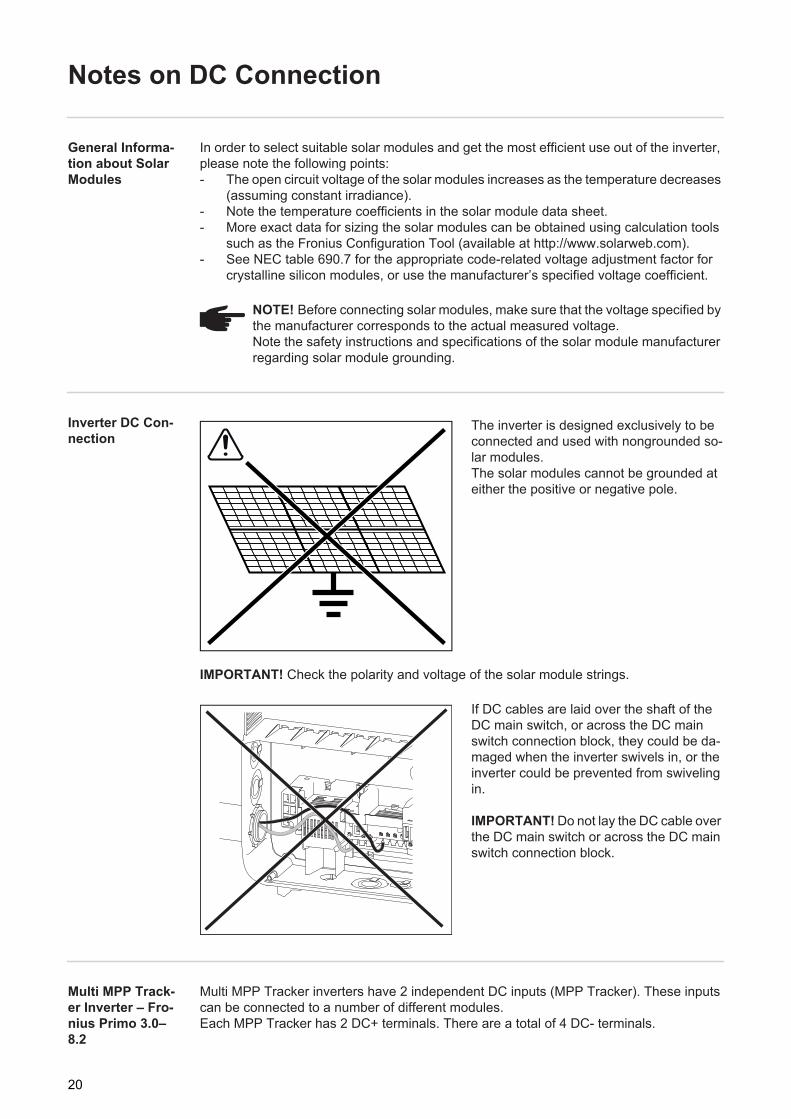
The inverter is designed exclusively to be connected and used with nongrounded so-lar modules. The solar modules cannot be grounded at either the positive or negative pole.
IMPORTANT! Check the polarity and voltage of the solar module strings.
If DC cables are laid over the shaft of the DC main switch, or across the DC main switch connection block, they could be da-maged when the inverter swivels in, or the inverter could be prevented from swiveling in.
IMPORTANT! Do not lay the DC cable over the DC main switch or across the DC main switch connection block.
Multi MPP Track-er Inverter – Fro-nius Primo 3.0–8.2
Multi MPP Tracker inverters have 2 independent DC inputs (MPP Tracker). These inputs can be connected to a number of different modules.Each MPP Tracker has 2 DC+ terminals. There are a total of 4 DC- terminals.
NOTE! Before connecting solar modules, make sure that the voltage specified by the manufacturer corresponds to the actual measured voltage. Note the safety instructions and specifications of the solar module manufacturer regarding solar module grounding.
20
EN-U
S
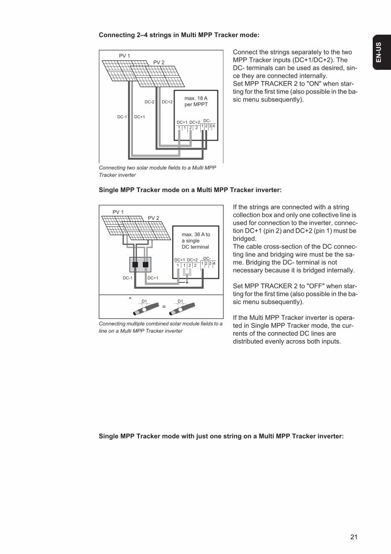
Connecting 2–4 strings in Multi MPP Tracker mode:
Connecting two solar module fields to a Multi MPP Tracker inverter
Connect the strings separately to the two MPP Tracker inputs (DC+1/DC+2). The DC- terminals can be used as desired, sin-ce they are connected internally. Set MPP TRACKER 2 to "ON" when star-ting for the first time (also possible in the ba-sic menu subsequently).
Single MPP Tracker mode on a Multi MPP Tracker inverter:
Connecting multiple combined solar module fields to a line on a Multi MPP Tracker inverter
If the strings are connected with a string collection box and only one collective line is used for connection to the inverter, connec-tion DC+1 (pin 2) and DC+2 (pin 1) must be bridged.The cable cross-section of the DC connec-ting line and bridging wire must be the sa-me. Bridging the DC- terminal is not necessary because it is bridged internally.
Set MPP TRACKER 2 to "OFF" when star-ting for the first time (also possible in the ba-sic menu subsequently).
If the Multi MPP Tracker inverter is opera-ted in Single MPP Tracker mode, the cur-rents of the connected DC lines are distributed evenly across both inputs.
Single MPP Tracker mode with just one string on a Multi MPP Tracker inverter:
DC-2
DC-DC-1
max. 18 A
per MPPT
PV 1
PV 2
1 21 2 3 41 2
DC+1 DC+2
DC+1
DC+2
PV 1PV 2
1
DC+1
DC-1
DC+2 DC-
11 2 3 4
2 2
D1 D1
=
*
*DC+1
max. 36 A to
a single
DC terminal
21
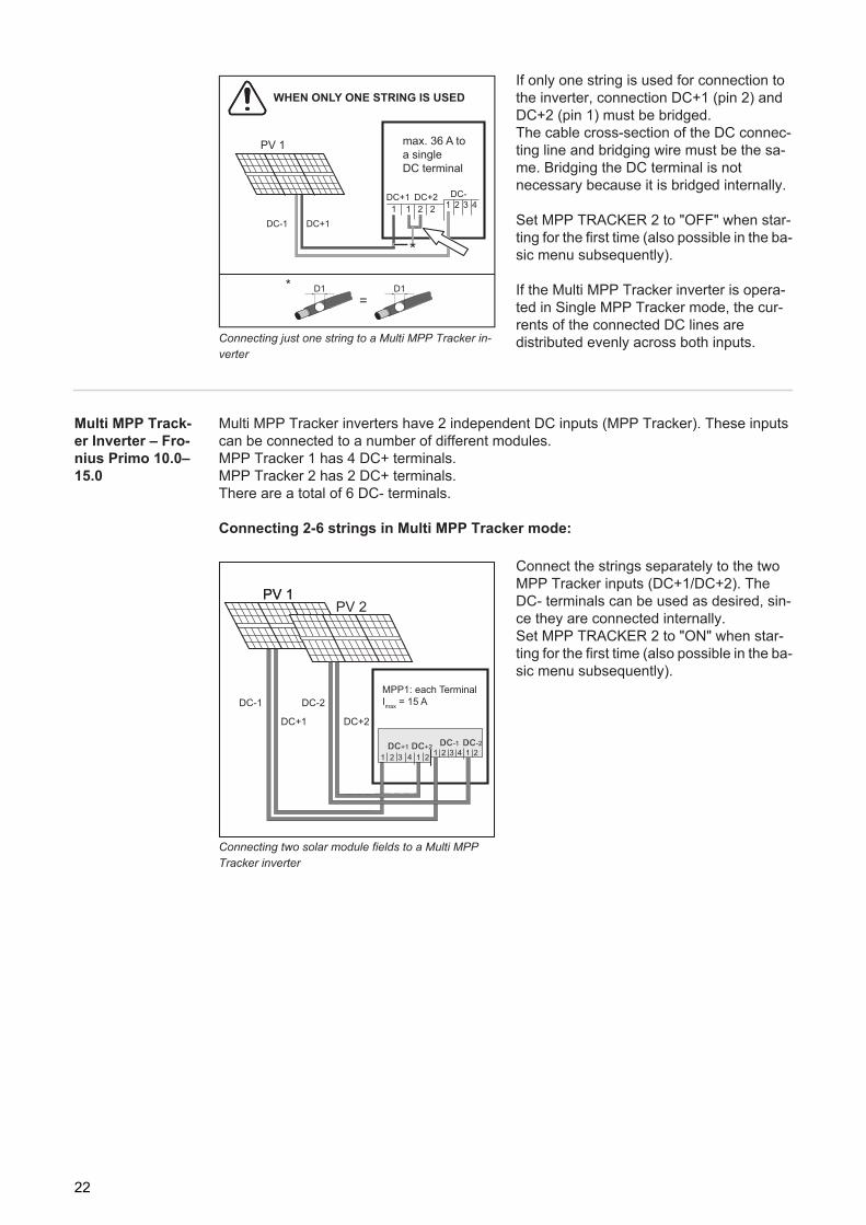
Connecting just one string to a Multi MPP Tracker in-verter
If only one string is used for connection to the inverter, connection DC+1 (pin 2) and DC+2 (pin 1) must be bridged.The cable cross-section of the DC connec-ting line and bridging wire must be the sa-me. Bridging the DC terminal is not necessary because it is bridged internally.
Set MPP TRACKER 2 to "OFF" when star-ting for the first time (also possible in the ba-sic menu subsequently).
If the Multi MPP Tracker inverter is opera-ted in Single MPP Tracker mode, the cur-rents of the connected DC lines are distributed evenly across both inputs.
Multi MPP Track-er Inverter – Fro-nius Primo 10.0–15.0
Multi MPP Tracker inverters have 2 independent DC inputs (MPP Tracker). These inputs can be connected to a number of different modules.MPP Tracker 1 has 4 DC+ terminals.MPP Tracker 2 has 2 DC+ terminals. There are a total of 6 DC- terminals.
Connecting 2-6 strings in Multi MPP Tracker mode:
Connecting two solar module fields to a Multi MPP Tracker inverter
Connect the strings separately to the two MPP Tracker inputs (DC+1/DC+2). The DC- terminals can be used as desired, sin-ce they are connected internally. Set MPP TRACKER 2 to "ON" when star-ting for the first time (also possible in the ba-sic menu subsequently).
PV 1
1
DC+1
DC-1
DC+2 DC-
11 2 3 4
2 2
D1 D1
=
*
DC+1
max. 36 A to
a single
DC terminal
WHEN ONLY ONE STRING IS USED
*
DC-1
PV 1PV 1PV 2
DC+1
DC-2
DC+2
MPP1: each Terminal
Imax
= 15 A
1
DCDC+1+1 DCDC+2+2 DCDC-1-1 DCDC-2-2
21 2 3 4 1 2
3 1 24
22
EN-U
S
Notes on Laying Data Communication Cables
Laying Data Com-munication Ca-bles
IMPORTANT! The inverter must not be operated with one option card and 2 knocked-out option card slots.In this case Fronius provides an appropriate dummy cover as an accessory:42,0405,2020 ... for Fronius Primo 3.8–8.242,0405,2094 ... for Fronius Primo 10.0–15.0
IMPORTANT! If data communication cables are wired into the inverter, observe the follow-ing points:- Provide separate conduits for data communication cables- Lay data communication cables in the supplied protective hose- Knock out the appropriate opening- Cleanly deburr the knocked-out opening
- Fronius Primo 3.9–8.2 only:Insert the supplied cable gland into the opening (if both openings are knocked out, an additional cable gland 42,0405,2019 is required)
- Clip the inverter onto the wall bracket- Guide the data communication cables through the cable glands from behind- When pivoting the inverter, ensure that the cables are not trapped, kinked, or dam-
aged in any other way. Do not loop the data communication cables.- Lay the data communication cables in the data communication area of the inverter and
connect to the Solar Net "IN" and "OUT" connections.Plug the termination plugs into the remaining Solar Net connections.
23
Notes on Clipping the Inverter into the Wall Bracket
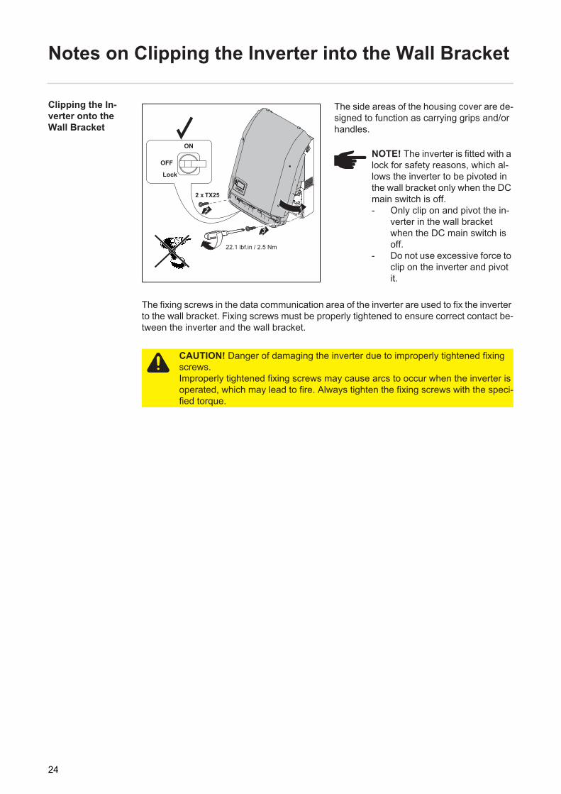
Clipping the In-verter onto the Wall Bracket
The side areas of the housing cover are de-signed to function as carrying grips and/or handles.
The fixing screws in the data communication area of the inverter are used to fix the inverter to the wall bracket. Fixing screws must be properly tightened to ensure correct contact be-tween the inverter and the wall bracket.
ON
OFF
Lock
22.1 lbf.in / 2.5 Nm
NOTE! The inverter is fitted with a lock for safety reasons, which al-lows the inverter to be pivoted in the wall bracket only when the DC main switch is off.- Only clip on and pivot the in-
verter in the wall bracket when the DC main switch is off.
- Do not use excessive force to clip on the inverter and pivot it.
CAUTION! Danger of damaging the inverter due to improperly tightened fixing screws.Improperly tightened fixing screws may cause arcs to occur when the inverter is operated, which may lead to fire. Always tighten the fixing screws with the speci-fied torque.
24
EN-U
S
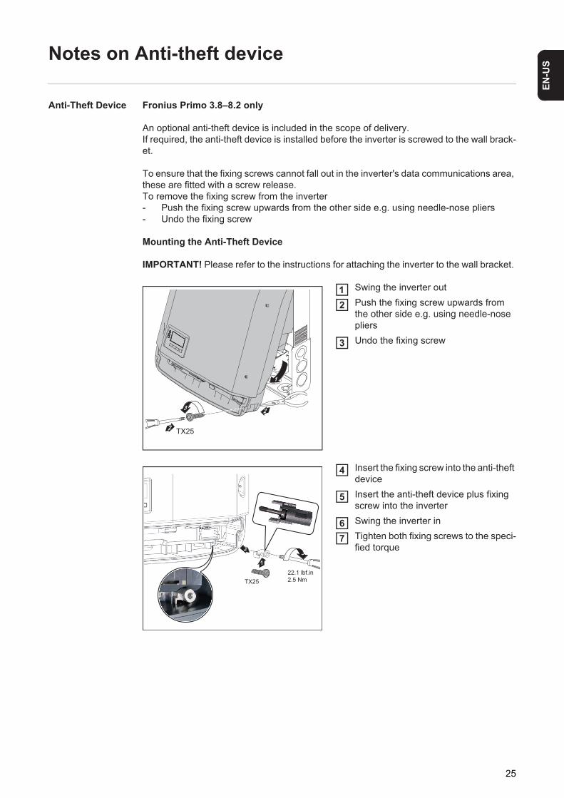
Notes on Anti-theft device
Anti-Theft Device Fronius Primo 3.8–8.2 only
An optional anti-theft device is included in the scope of delivery. If required, the anti-theft device is installed before the inverter is screwed to the wall brack-et.
To ensure that the fixing screws cannot fall out in the inverter's data communications area, these are fitted with a screw release. To remove the fixing screw from the inverter- Push the fixing screw upwards from the other side e.g. using needle-nose pliers- Undo the fixing screw
Mounting the Anti-Theft Device
IMPORTANT! Please refer to the instructions for attaching the inverter to the wall bracket.
Swing the inverter outPush the fixing screw upwards from the other side e.g. using needle-nose pliersUndo the fixing screw
Insert the fixing screw into the anti-theft deviceInsert the anti-theft device plus fixing screw into the inverterSwing the inverter inTighten both fixing screws to the speci-fied torque
2
2
1
TX25
12
3
2
22.1 lbf.in
2.5 Nm
3
1
TX25
4
5
67
25
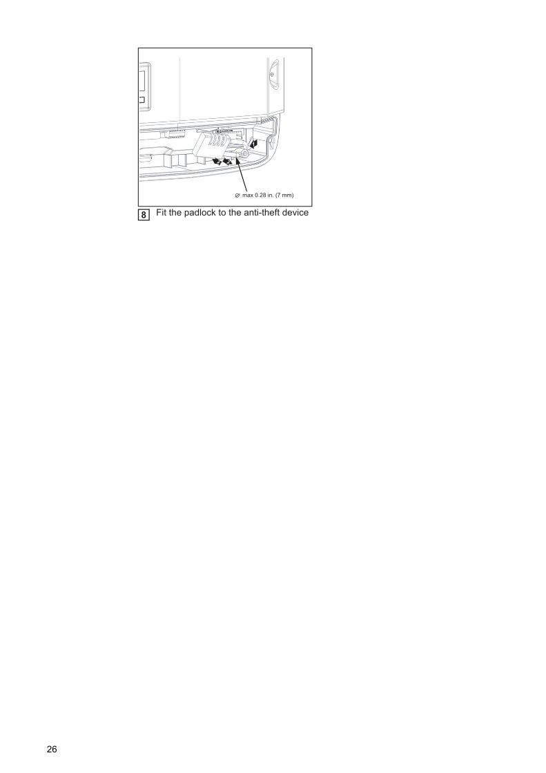
Fit the padlock to the anti-theft device
2 2
1
max 0.28 in. (7 mm)
8
26

EN-U
S
Notes on Software Updates
Notes on Soft-ware Updates
Insert the USB stick in the inverter data communication areaAccess the Setup menuSelect the "USB" menu itemSelect "Update Software"Install the update
USB+
3
54 4
1
2 2
1
2345
27
USB Stick as a Data Logger and for Updating Invert-er Software
USB stick as a data logger
A USB stick connected to the USB A socket can act as a data logger for an inverter.
Logging data saved to the USB stick can at any time- be imported into the Fronius Solar.access software via the included FLD file,- be viewed directly in third-party applications (e.g., Microsoft® Excel) via the included
CSV file.
Older Excel versions (up to Excel 2007) have a row limit of 65536.
Data on the USB stick
If the USB stick is used as a datalogger, three files are automatically created:
- FRONIUS.sys system file: This file saves information from the inverter that is irrelevant to the customer. The file must not be deleted individually. Only delete all files together (sys, fld, csv).
- DALO.fld log file: Log file for reading out data in Fronius Solar.access.
You can find additional information on the Fronius Solar.access Software in the "DAT-COM Detail" operating instructions at http://www.fronius.com
- DATA.csv log file: A log file for reading out data in a spreadsheet program (e.g., Microsoft® Excel)
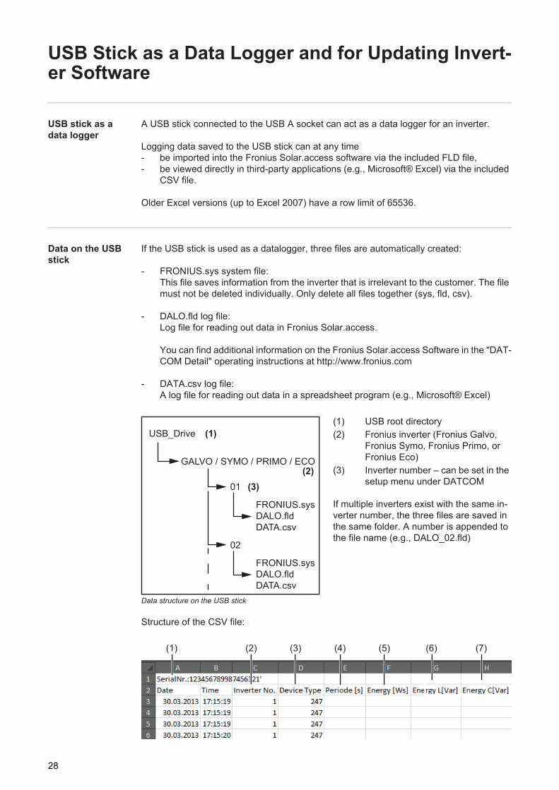
Data structure on the USB stick
(1) USB root directory(2) Fronius inverter (Fronius Galvo,
Fronius Symo, Fronius Primo, or Fronius Eco)
(3) Inverter number – can be set in the setup menu under DATCOM
If multiple inverters exist with the same in-verter number, the three files are saved in the same folder. A number is appended to the file name (e.g., DALO_02.fld)
Structure of the CSV file:
USB_Drive (1)
(2)01 (3)
02
FRONIUS.sys
DALO.fld
DATA.csv
FRONIUS.sys
DALO.fld
DATA.csv
GALVO / SYMO / PRIMO / ECO
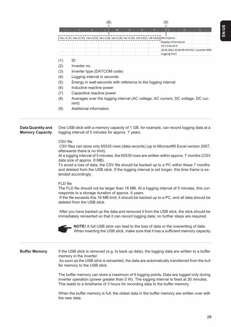
(1) (2) (3) (4) (5) (6) (7)
28
EN-U
S
(1) ID(2) Inverter no.(3) Inverter type (DATCOM code)(4) Logging interval in seconds(5) Energy in watt-seconds with reference to the logging interval(6) Inductive reactive power(7) Capacitive reactive power(8) Averages over the logging interval (AC voltage, AC current, DC voltage, DC cur-
rent)(9) Additional information
Data Quantity and Memory Capacity
One USB stick with a memory capacity of 1 GB, for example, can record logging data at a logging interval of 5 minutes for approx. 7 years.
CSV file CSV files can store only 65535 rows (data records) (up to Microsoft® Excel version 2007, afterwards there is no limit). At a logging interval of 5 minutes, the 65535 rows are written within approx. 7 months (CSV data size of approx. 8 MB). To avoid a loss of data, the CSV file should be backed up to a PC within these 7 months and deleted from the USB stick. If the logging interval is set longer, this time frame is ex-tended accordingly.
FLD fileThe FLD file should not be larger than 16 MB. At a logging interval of 5 minutes, this cor-responds to a storage duration of approx. 6 years. If the file exceeds this 16 MB limit, it should be backed up to a PC, and all data should be deleted from the USB stick.
After you have backed up the data and removed it from the USB stick, the stick should be immediately reinserted so that it can record logging data; no further steps are required.
Buffer Memory If the USB stick is removed (e.g. to back up data), the logging data are written to a buffer memory in the inverter. As soon as the USB stick is reinserted, the data are automatically transferred from the buf-fer memory to the USB stick.
The buffer memory can store a maximum of 6 logging points. Data are logged only during inverter operation (power greater than 0 W). The logging interval is fixed at 30 minutes. This leads to a timeframe of 3 hours for recording data to the buffer memory.
When the buffer memory is full, the oldest data in the buffer memory are written over with the new data.
(8) (9)
NOTE! A full USB stick can lead to the loss of data or the overwriting of data. When inserting the USB stick, make sure that it has a sufficient memory capacity.
29
IMPORTANT! The buffer memory requires a constant power supply. If there is an AC power outage during operation, all data in the buffer memory are lost. The automatic night switch-off must be deactivated so that the data are not lost at night (set "Night Mode" to ON – see chapter "Setting and Displaying Menu Items," section "Display-ing and Setting Parameters in the 'DATCOM' Menu Item").On the Fronius Eco, the buffer memory also functions with just a DC supply.
Suitable USB Sticks
Due to the number of USB sticks on the market, we cannot guarantee that every USB stick will be recognized by the inverter.
Fronius recommends using only certified, industrial USB sticks (look for the USB-IF logo).
The inverter supports USB sticks using the following file systems:- FAT12- FAT16- FAT32
Fronius recommends that the USB stick only be used for recording logging data or for up-dating the inverter software. USB sticks should not contain any other data.
USB Stick for Up-dating Inverter Software
The USB stick can be used to help end customers update inverter software via the USB menu item in the SETUP menu item: the update file is first saved on the USB stick and then transferred to the inverter. The update file must be saved in the USB stick root directory.
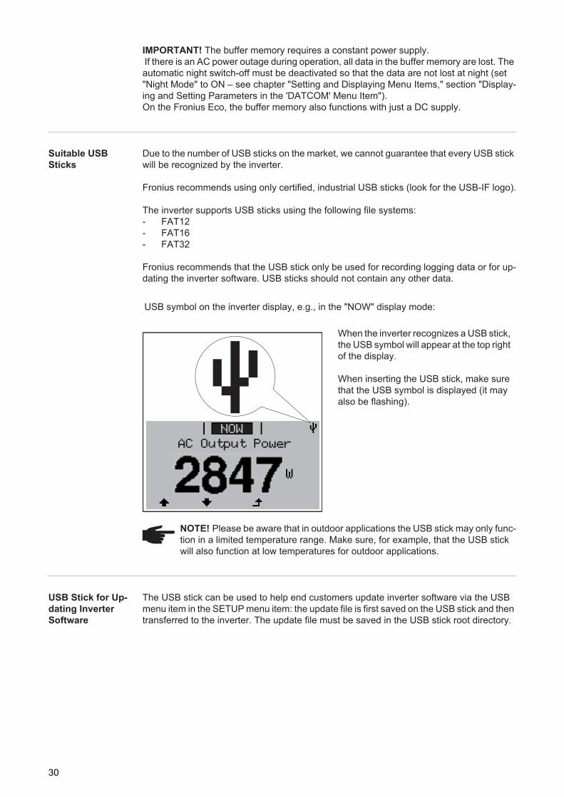
USB symbol on the inverter display, e.g., in the "NOW" display mode:
When the inverter recognizes a USB stick, the USB symbol will appear at the top right of the display.
When inserting the USB stick, make sure that the USB symbol is displayed (it may also be flashing).
NOTE! Please be aware that in outdoor applications the USB stick may only func-tion in a limited temperature range. Make sure, for example, that the USB stick will also function at low temperatures for outdoor applications.
AC Output Power
NOW
30

EN-U
S
Removing the USB Stick Safety information for removing a USB stickIMPORTANT! To prevent a loss of data, the connected USB stick should only be removed under the following conditions:- via the SETUP and "Safely remove
USB / hardware" menu items- when the "Data Transfer" LED is no
longer flashing or illuminated.
Do not disconnect
USB-Stick
while LED is flashing!
X
31

Notes on Maintenance
Maintenance
Maintenance and repair work must only be carried out by authorised personnel.
Cleaning The inverter and the display can be cleaned with a damp cloth if necessary. Do not use any cleaning agents, abrasive cleaners, or solvents to clean the inverter.
NOTE! For horizontal installation positions and when installing outside: check once per year that all screws are secured tightly.
32
EN-U
S
Serial Number Sticker for Customer Use
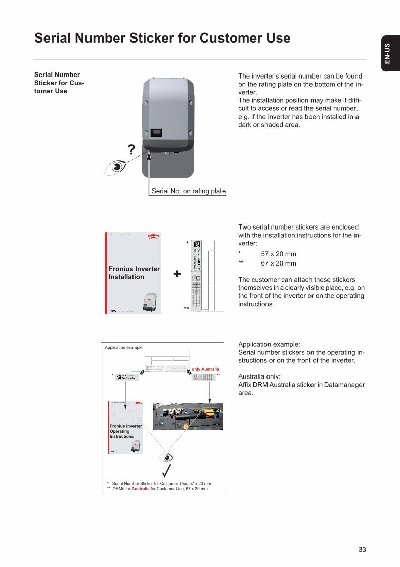
Serial Number Sticker for Cus-tomer Use
The inverter's serial number can be found on the rating plate on the bottom of the in-verter.The installation position may make it diffi-cult to access or read the serial number, e.g. if the inverter has been installed in a dark or shaded area.
Two serial number stickers are enclosed with the installation instructions for the in-verter:* 57 x 20 mm** 67 x 20 mm
The customer can attach these stickers themselves in a clearly visible place, e.g. on the front of the inverter or on the operating instructions.
Application example:Serial number stickers on the operating in-structions or on the front of the inverter.
Australia only:Affix DRM Australia sticker in Datamanager area.
Serial No. on rating plate
?
+Fronius InverterInstallation
*
**
DRM‘s forAustralia
I94/8I72/6
I5IO3CL/0
IO1GND
GNDD-
3/7I81/5I6
I4RG/0IO2
12V+12V+
IO0D+
DRM‘s forAustralia
I94/8
I72/6
I5 IO3CL/0
IO1 GND GND D-
3/7I8
1/5I6 I4
RG/0IO2 12V+12V+IO0 D+
Fronius InverterOperatingInstructions
* Serial Number Sticker for Customer Use, 57 x 20 mm
** DRMs for Australia for Customer Use, 67 x 20 mm
* **
Application example
DRM‘s forAustralia
I94/8
I72/6
I5 IO3CL/0
IO1 GND GND D-
3/7I8
1/5I6 I4
RG/0IO2 12V+12V+IO0 D+
2only Australia1
33

34

35
EN-U
S

Fronius Worldwide - www.fronius.com/addresses
Under http://www.fronius.com/addresses you will find all addresses of our sales branches and partner firms!
Fronius International GmbH4600 Wels, Froniusplatz 1, AustriaE-Mail: [email protected]://www.fronius.com
Fronius USA LLC Solar Electronics Division6797 Fronius Drive, Portage, IN 46368E-Mail: [email protected]://www.fronius-usa.com