fronius primo - installation
TRANSCRIPT

Fronius prints on elemental chlorine free paper (ECF) sourced from certified sustainable forests (FSC).
/ Perfect Charging / Perfect Welding / Solar Energy
Fronius Primo - InstallationEN
Installation instructions
42,0426,0204,EN 020-26112021


ContentsInstallation location and position 5
Explanation of safety notices 5Safety 5Proper use 6Explanation of symbols and choice of location 7Installation position 8General comments regarding choice of location 9
Attaching the Mounting Bracket 11Safety 11Selecting wall plugs and screws 11Recommended screws 11Opening the inverter 11Do not warp or deform the mounting bracket 12Fitting the mounting bracket to a wall 13Attaching the mounting bracket 13Mounting the inverter on a mast 14Fitting the mounting bracket to metal supports 14
Connecting the inverter to the public grid (AC side) 15Safety 15Monitoring the grid 15AC terminals 16Type of AC cable 16Preparing the aluminium cables for connection 16Requirements for the neutral conductor 17Connecting the inverter to the public grid (AC) 17Routing the AC cables 17Maximum fuse rating on alternating current side 18
Connecting solar module strings to the inverter 20Safety 20General comments regarding solar modules 22DC terminals 22Connecting aluminium cables 22Solar module strings - checking the polarity and voltage 23Notes regarding dummy devices 23Do not earth solar modules 24Inverter DC connection 24Cable routing in the DC area 26Multi MPP tracker inverters - Fronius Primo 3.0 - 8.2 26
Data communication 28Routing data communication cables 28Installing the Datamanager in the inverter 28
Australian Conduits 31Tightly sealing the conduits 31Seal conduits 31
Attaching the inverter to the mounting bracket 32Attaching the inverter to the mounting bracket 32
Starting for the first time 34Starting the inverter for the first time 34
Notes regarding software updates 37Notes regarding software updates 37
USB Stick as a Data Logger and for Updating Inverter Software 38USB flash drive as a datalogger 38Data on the USB flash drive 38Data volume and storage capacity 39Buffer memory 40Suitable USB flash drives 40USB stick for updating the inverter software 41Removing the USB flash drive 41
Notes regarding maintenance 42Maintenance 42
3
EN

Cleaning 42Serial Number Sticker for Customer Use 43
Serial number sticker for customer use 43
4

Installation location and position
Explanation ofsafety notices DANGER!
Indicates immediate danger.▶ If not avoided, death or serious injury will result.
WARNING!
Indicates a potentially hazardous situation.▶ If not avoided, death or serious injury may result.
CAUTION!
Indicates a situation where damage or injury could occur.▶ If not avoided, minor injury and/or damage to property may result.
NOTE!
Indicates a risk of flawed results and possible damage to the equipment.
Safety WARNING!
Danger due to incorrect operation and incorrectly performed work.This can result in serious injury and damage to property.▶ Only qualified personnel are authorised to commission your inverter and only within
the scope of the respective technical regulations.▶ Read the Installation and Operating Instructions before installing and commissioning
the equipment.
WARNING!
Danger due to work that has been carried out incorrectly.This may result in serious injury and damage to property.▶ Surge protective devices must only ever be installed and connected by a qualified
electrical installation engineer!▶ Follow the safety rules.
▶ Ensure that both the AC side and the DC side of the inverter are de-energised be-fore carrying out any installation and connection work.
5
EN

Fire prevention
CAUTION!
Danger due to poor or unprofessional installation.This may result in damage to inverters and other live photovoltaic system components.Poor or unprofessional installation can cause overheating of cables and terminal connec-tions and result in arcs. These can cause heat damage, which in turn may lead to fires.
Observe the following when connecting AC and DC cables:▶ Tighten all terminals to the torque specified in the operating instructions
▶ Tighten all grounding terminals (PE / GND), including free ones, to the torque spe-cified in the operating instructions
▶ Do not overload cables
▶ Check cables for damage and verify that they are laid correctly
▶ Take note of the safety instructions, Operating Instructions and any local connectionregulations
▶ Using fastening screws, always screw the inverter firmly to the mounting bracket tothe torque specified in the Operating Instructions.
▶ Ensure that the fastening screws are tight before starting the inverter!
Note! Fronius will not accept any costs associated with production downtimes, installercosts, etc., that may arise as the result of a detected arc and its consequences. Froniusaccepts no liability for fires that can occur despite the presence of the integrated arc de-tection/extinguishing system (e.g. fires caused by a parallel arc).
Note! After an arc has been detected, the entire photovoltaic system must be checkedfor possible damage before resetting the inverter.
Observe the manufacturer's connection, installation and operating instructions at alltimes. To reduce the hazard potential to a minimum, perform all installation and connec-tion work carefully according to the instructions and regulations.Refer to the device Installation Instructions for the tightening torques to be used at therelevant terminal connections.
Proper use The inverter is designed to be connected and used exclusively in conjunction with un-grounded solar modules. The solar modules must not be grounded at either the positiveor negative pole.
The solar inverter is intended exclusively to convert direct current from solar modules in-to alternating current and to feed this into the public grid.Utilisation not in accordance with the intended purpose comprises:- any use above and beyond this purpose- making any modifications to the inverter that have not been expressly approved by
Fronius- the installation of components that are not distributed or expressly approved by
Fronius.
Fronius shall not be liable for any damage resulting from such action.No warranty claims will be entertained.
Proper use also includes- carefully reading and obeying all the instructions and all the safety and danger no-
tices in the operating instructions- performing all stipulated inspection and maintenance work- installation as specified in the operating instructions
6

When designing the photovoltaic system, ensure that all of its components are operatedwithin their permitted operating ranges at all times.
Observe all the measures recommended by the solar module manufacturer to ensure thelasting maintenance of the properties of the solar module.
Obey the regulations of the power supply company regarding energy fed into the grid.
Explanation ofsymbols andchoice of location
The inverter is suitable for indoor installation.
The inverter is suitable for outdoor installation.
Because of its IP 65 protection class, the inverter is resistant to waterjets from any direction and can also be used in damp environments.
In order to minimise the heating up of the inverter, do not expose it todirect insolation. Install the inverter in a protected location, e.g. in thevicinity of the solar modules or beneath the eaves.
Can be used at altitudes of up to 4000 m
IMPORTANT! The inverter must not be installed or used at altitudesabove 4000 m.
NH3 Do not install the inverter in:
- Areas where ammonia, corrosive vapours, acids or salts arepresent(e.g. fertiliser stores, ventilation openings from cattle sheds,chemical plants, tanneries, etc.)
7
EN

During certain operating phases the inverter may produce a slightnoise. For this reason it should not be installed close to living areas.
Do not install the inverter in:- Places where there is an increased risk of damage from farm an-
imals (horses, cattle, sheep, pigs, etc.)- Stables or adjoining areas- Storage areas for hay, straw, chaff, animal feed, fertilisers, etc.
Do not install the inverter in:- Places and environments subject to a heavy build-up of dust- Places and environments in which a heavy build-up of dust con-
taining conductive particles (e.g. iron chips) is likely
Do not install the inverter in:- Greenhouses- Storage or processing areas for fruit, vegetables or viticulture
products- Areas used in the preparation of grain, green fodder or animal
feeds
Installation posi-tion
The inverter is suitable for vertical installation on a vertical wall orcolumn.
The inverter is suitable for a horizontal installation position.
The inverter is suitable for installation on a sloping surface.
Do not install the inverter on a sloping surface with its connection sock-ets at the top.
8

Do not install the inverter at an angle on a vertical wall or column.
Do not install the inverter horizontally on a vertical wall or pillar.
Do not install the inverter on a vertical wall or pillar with its connectionsockets facing upwards.
Do not install the inverter overhanging with the connection sockets at thetop.
Do not install the inverter overhanging with the connection sockets at thebottom.
Do not install the inverter on the ceiling.
General com-ments regardingchoice of location
Please note the following criteria when choosing a location for the inverter:
Only install on a solid, non-flammable surface
9
EN

Max. ambient temperatures:-40 °C / +55 °C
Relative humidity:0-100%
The airflow within the inverter isfrom the left and right to the top(cold air taken in from the leftand right, hot air dissipated outof the top).The exhaust air can reach atemperature of 70 °C.
If the inverter is installed in a switch cabinet or a similar sealed area, then forced-airventilation must be provided to ensure adequate heat dissipation.
If the inverter is to be installed on the outer wall of a cattle shed, maintain a minimumall-round clearance of 2 m between the inverter and all ventilation and other openingsin the building.The installation location must not be exposed to ammonia, corrosive vapours, salts oracids.
10

Attaching the Mounting Bracket
Safety WARNING!
Danger due to residual voltage in capacitors.This may result in an electric shock.▶ Wait for the capacitors to discharge. The discharge time is five minutes.
CAUTION!
Danger due to dirt or water on the terminals and contacts of the inverter's connec-tion area.This may result in damage to the inverter.▶ When drilling, ensure that terminals and contacts in the connection area do not be-
come dirty or wet.▶ The mounting bracket without a power stage set does not conform to the protection
class of the inverter as a whole, and therefore must not be installed without a powerstage set.
▶ The mounting bracket should be protected from dirt and moisture during installation.
Note! Degree of protection IP 65 is only applicable if- the inverter is placed in the mounting bracket and permanently attached using
screws,- the cover for the data communication area is permanently attached to the inverter
with screws.
Degree of protection IP 20 applies to the mounting bracket with no inverter and the vent-ing duct.
Selecting wallplugs and screws
Important! Different fixings may be required to fit the mounting bracket depending on thetype of underlying surface. Fixings are therefore not included in the scope of supply ofthe inverter. The installer is responsible for selecting the right type of fixing.
Recommendedscrews
To install the inverter, the manufacturer recommends the use of steel or aluminiumscrews with a diameter of 6 - 8 mm.
Opening the in-verter WARNING!
Danger from inadequate ground conductor connection.This can result in serious injury and damage to property.▶ The housing screws provide a suitable ground conductor connection for grounding
the housing and must NOT be replaced by any other screws that do not provide areliable ground conductor connection.
11
EN

1 2
3 4
Do not warp ordeform themounting bracket
Note! When fitting the mounting bracket to the wall, ensure that the mounting bracketdoes not become warped or deformed.
12

Fitting the mount-ing bracket to awall
Tip: Install the inverter so that its display is at eyelevel
1 2
3 Note! When mounting the mounting brack-et on the wall, ensure that the mountingbracket does not become warped or de-formed.
Attaching themounting bracket
1 2
13
EN

3
Mounting the in-verter on a mast
Example of a mast fixing kit
When mounting the inverter on a mast or avertical carrier, Fronius recommends theuse of a standard mast fixing kit.
This kit enables the inverter to be mountedon round or rectangular masts with variouscross-sections.
Fitting the mount-ing bracket tometal supports
The mounting bracket must be affixed at a minimum of four points.
1
14

Connecting the inverter to the public grid (AC side)
Safety WARNING!
Incorrect operation or poorly executed work can cause serious injury or damage.Only qualified staff are authorised to commission your inverter and only within the scopeof the respective technical regulations. Read the Installation and Operating Instructionsbefore installing and commissioning the equipment.
WARNING!
An electric shock can be fatal.Danger due to grid voltage and DC voltage from solar modules that are exposed to light.▶ Ensure that both the AC side and the DC side of the inverter are de-energised be-
fore carrying out any connection work.▶ Only an authorised electrical engineer is permitted to connect this equipment to the
public grid.
WARNING!
An electric shock can be fatal.Danger due to grid voltage and DC voltage from solar modules.▶ The DC main switch is only to be used to de-energise the power stage set. The con-
nection area is still live when the DC main switch is switched off.▶ Ensure that the power stage set and connection area are disconnected from one an-
other before carrying out any maintenance or service tasks.▶ The power stage set is only to be disconnected from the mounting bracket once it is
de-energised.▶ Maintenance and servicing in the power stage set of the inverter must only be car-
ried out by Fronius-trained service technicians.
CAUTION!
Risk of damage to the inverter as the result of incorrectly tightened terminals.Incorrectly tightened terminals can cause heat damage to the inverter that may result ina fire. When connecting AC and DC cables, ensure that all the terminals are tightened tothe specified torque.
IMPORTANT! To ensure a proper ground connection, all three PE grounding terminalsmust be tightened to the specified torque when the inverter is installed.
Monitoring thegrid
To provide the best possible grid monitoring, the resistance in the leads to the AC-sideterminals should be as low as possible.
15
EN

AC terminals PE Ground conductor / earthingL1 Phase conductorN Neutral conductor
Max. cross-section of each conductorcable:16 mm²
Min. cross-section of each conductorcable:in accordance with the fuse rating on theAC side, but at least 2.5 mm²
The AC cables can be connected to theAC terminals without ferrules.
IMPORTANT! When using ferrules for AC cables with a cross-section of 16 mm², the fer-rules must be crimped with a right-angled cross-section.The use of ferrules with insulating collars is only permitted up to a max. cable cross-sec-tion of 10 mm².
Type of AC cable The following types of AC cable can be connected to the AC terminals of the inverter:
- Copper or aluminium: solid round conductor- Copper: fine-stranded round conductor, up to conductor class 4
Preparing the alu-minium cablesfor connection
The AC-side terminals are suitable for connecting single-wire, round aluminium cables.Because of the formation of a non-conductive oxide layer due to the reaction of alumini-um with air, the following points must be considered when connecting aluminium cables:- the reduced rated currents for aluminium cables- the connection conditions listed below
Always follow the cable manufacturer instructions when using aluminium cables.
When designing cable cross-sections, take local regulations into account.
Connection conditions:
1 Carefully clean the oxide layer from the bare end of the cable by scraping it, e.g. witha knife
IMPORTANT! Do not use brushes, files or emery paper, as the aluminium particles gettrapped and can be transferred to other conductors.
2 Once the oxide layer is removed, rub the end of the cable with a neutral grease,such as non-acidic and non-alkaline Vaseline
3 Immediately connect the cable end to the terminal
IMPORTANT!Repeat the procedure if the cable has been disconnected and is to be re-connected.
16

Requirements forthe neutral con-ductor
Note!- Ensure that the grid neutral conductor is grounded. This may not be the case for IT
grids (insulated grids with no grounding); it will then not be possible to use the invert-er.
- In order to use the inverter, the neutral conductor must be connected. A neutral con-ductor that is too small may adversely affect the inverter feeding energy into the grid.The neutral conductor must therefore be the same size as the other live conductors.
Connecting theinverter to thepublic grid (AC)
1 2
Note! Observe the torque values marked on the sideunderneath the terminals.
3 4
Routing the ACcables
Note!- Form loops with the AC cables when connecting them to the AC terminals.- When securing the AC cables using a metric screw joint, ensure that the loops do
not protrude beyond the connection area.Otherwise, under certain circumstances it may no longer be possible to close the in-verter.
IMPORTANT! The PE ground conductor of the AC cable must be laid in such a way thatit is the last to be disconnected in the event that the strain-relief device should fail.This can be ensured, for example, by making it somewhat longer and by laying it in aloop.
17
EN

If AC cables are laid over the shaft of the DC main switch or across the connection blockof the DC main switch, they may be damaged when the inverter is swung in, or they mayeven prevent the inverter from being swung in.
IMPORTANT! Do not lay AC cables over the shaft of the DC main switch or across theconnection block of the DC main switch.
If overlength AC or DC cables are to belaid in loops in the connection area, attachthe cables with cable ties to the eyeletsprovided on the top and bottom of the con-nection block.
Maximum fuserating on alternat-ing current side
Inverter Phases Max. output Max. output over-current protection
Fronius Primo 3.0-1 1 3000 W 1 x C 63 A
Fronius Primo 3.5-1 1 3500 W 1 x C 63 A
Fronius Primo 3.6-1 1 3600 W 1 x C 63 A
Fronius Primo 4.0-1 1 4000 W 1 x C 63 A
18

Inverter Phases Max. output Max. output over-current protection
Fronius Primo 4.6-1 1 4600 W 1 x C 63 A
Fronius Primo 5.0-1 AUS 1 5000 W 1 x C 63 A
Fronius Primo 5.0-1 1 5000 W 1 x C 63 A
Fronius Primo 5.0-1 SC 1 5000 W 1 x C 63 A
Fronius Primo 6.0-1 1 6000 W 1 x C 63 A
Fronius Primo 8.2-1 1 8200 W 1 x C 63 A
NOTE!
Local regulations, the energy company or other factors may require a residual cur-rent protective device (RCD) in the AC connection lead.For this situation, a type A residual current protective device is generally adequate. Inparticular cases, and depending on local factors, however, the type A residual currentprotective device may trip at the wrong time.For this reason, Fronius recommends that an RCD suitable for frequency converters beused.
19
EN

Connecting solar module strings to the inverter
Safety WARNING!
Danger due to incorrect operation and incorrectly performed work.This can result in serious injury and damage to property.▶ Only qualified staff are authorised to commission your inverter and only within the
scope of the respective technical regulations.▶ Read the Installation and Operating Instructions before installing and commissioning
the equipment.
WARNING!
Danger due to grid voltage and DC voltage from solar modules that are exposed tolight.This may result in an electric shock.▶ Ensure that both the AC side and the DC side of the inverter are de-energised be-
fore carrying out any connection work.▶ Only an authorised electrical engineer is permitted to connect this equipment to the
public grid.
WARNING!
Risk of electric shock if the solar module ground is not grounded or is not groun-ded properly.An electric shock can be fatal.▶ To comply with IEC 62109-2:2011, any grounding required by the manufacturer of
the solar module ground within the inverter must only be carried out via the specifiedfuse.
WARNING!
Danger from DC voltage in solar modules.An electric shock can be fatal. The inverter's insulation monitoring is deactivated whenthe solar modules are grounded.▶ Ensure that grounded solar modules are assembled so that they are insulated ac-
cording to Protection Class II▶ Place the relevant safety sticker in a clearly visible place on the photovoltaic system
▶ Configure the inverter so that an error message is displayed if the fuse trips.
WARNING!
Danger due to grid voltage and DC voltage from solar modules.This may result in an electric shock.▶ The DC main switch is only to be used to de-energise the power stage set. The con-
nection area is still live when the DC main switch is switched off.▶ Ensure that the power stage set and connection area are disconnected from one an-
other before carrying out any maintenance or service tasks.▶ The power stage set, which is enclosed in a separate housing, must only be discon-
nected from the connection area when in a de-energized state.▶ Maintenance and servicing in the power stage set of the inverter must only be car-
ried out by Fronius-trained service technicians.
20

WARNING!
Danger from inadequate ground conductor connection.This can result in serious injury and damage to property.▶ The housing screws provide a suitable ground conductor connection for grounding
the housing and must NOT be replaced by any other screws that do not provide areliable ground conductor connection.
CAUTION!
Danger due to dirt or water on the terminals and contacts of the connection area.This may result in damage to the inverter.▶ When drilling, ensure that terminals and contacts in the connection area do not be-
come dirty or wet.▶ The mounting bracket without a power stage set does not conform to the protection
class of the inverter as a whole, and therefore must not be installed without a powerstage set. The mounting bracket should be protected from dirt and moisture duringinstallation.
CAUTION!
Danger due to incorrectly tightened terminals.This may result in heat damage to the inverter, which may lead to fire.▶ When connecting AC and DC cables, ensure that all the terminals are tightened to
the specified torque.
CAUTION!
Danger due to overloading.This may result in damage to the inverter.▶ The maximum amperage when connecting to a single DC terminal is 36 A.
▶ Connect the DC+ and DC- cables to the DC+ and DC- terminals on the inverter, tak-ing care to ensure that the polarity is correct.
NOTE! If solar modules are grounded by a built-in grounding protection device in the in-verter, they will not be grounded if the DC main switch is in the OFF position.
NOTE! When connecting aluminium cables:- Observe national and international guidelines regarding the connection of aluminium
cables- Follow the instructions of the cable manufacturer.- Check every year that the cables are securely attached in accordance with the spe-
cified torque.
NOTE! The solar modules connected to the inverter must comply with the IEC 61730Class A standard.
NOTE! When photovoltaic modules are exposed to light, they supply current to the in-verter.
NOTE! Ensure the polarity is correct when connecting the DC cables.
NOTE! For grounding solar module frames or racks, the relevant specifications from thesolar module manufacturer must be taken into account along with national guidelines.
NOTE! If the inverter is installed in Australia or New Zealand (required standard: AS-4777.2:2020), the following applies:
21
EN

- Functional grounding isnot permitted- The inverter must not be used as part of a three-phase combination, as there is no
communication link between the inverters
General com-ments regardingsolar modules
To enable suitable solar modules to be chosen and to use the inverter as efficiently aspossible, it is important to bear the following points in mind:- If insolation is constant and the temperature is falling, the open circuit voltage of the
solar modules will increase.- The temperature coefficients on the solar modules data sheet must be observed- More exact values for dimensioning the solar modules can be provided by suitable
calculation programs, like the Fronius Solar.configurator (which can be downloadedfrom www.fronius.com).
NOTE!
Before connecting up the solar modules, check that the voltage for the solar mod-ules specified by the manufacturer corresponds to the actual measured voltage.
The solar module manufacturer's safety instructions and regulations regarding solarmodule grounding must be observed.
DC terminals Max. cross-section of each DC cable:16 mm²
Min. cross-section of each DC cable:2.5 mm²
The DC cables can be connected to theDC terminals without ferrules.
NOTE!
To ensure effective strain relief of thesolar module strings, only use cableswith identical cross-sections.
IMPORTANT! When using ferrules for DC cables with a cross-section of 16 mm², the fer-rules must be crimped with a right-angled cross-section.The use of ferrules with insulating collars is only permitted up to a max. cable cross-sec-tion of 10 mm².
Connecting alu-minium cables
The DC-side terminals are suitable for connecting single-wire, round aluminium cables.Because of the formation of a non-conductive oxide layer due to the reaction of alumini-um with air, the following points must be considered when connecting aluminium cables:
22

- the reduced rated currents for aluminium cables- the connection conditions listed below
Note! Always follow the cable manufacturer instructions when using aluminium cables.
Note! When designing cable cross-sections, take local regulations into account.
Connection conditions:
1 Carefully clean the oxide layer from the bare end of the cable by scraping it, e.g. witha knife
IMPORTANT! Do not use brushes, files or emery paper, as the aluminium particles gettrapped and can be transferred to other conductors.
2 Once the oxide layer is removed, rub the end of the cable with a neutral grease,such as non-acidic and non-alkaline Vaseline
3 Immediately connect the cable end to the terminal
IMPORTANT! Repeat the procedure if the cable has been disconnected and is to be re-connected.
Solar modulestrings - check-ing the polarityand voltage
CAUTION!
Danger due to incorrect polarity andvoltage.This may result in damage to the inverter.▶ Check the polarity and voltage of the
solar module strings before makingthe connection
Notes regardingdummy devices
A dummy device is not suitable for connecting operationally to a photovoltaic system,and must only ever be used for demonstration purposes. Dummy devices are indicatedas such on their rating plate.
IMPORTANT! Never connect DC cables to the DC connection sockets on a dummydevice.
The connection of de-energised cables or sections of cable for demonstration purposesis permissible.
23
EN
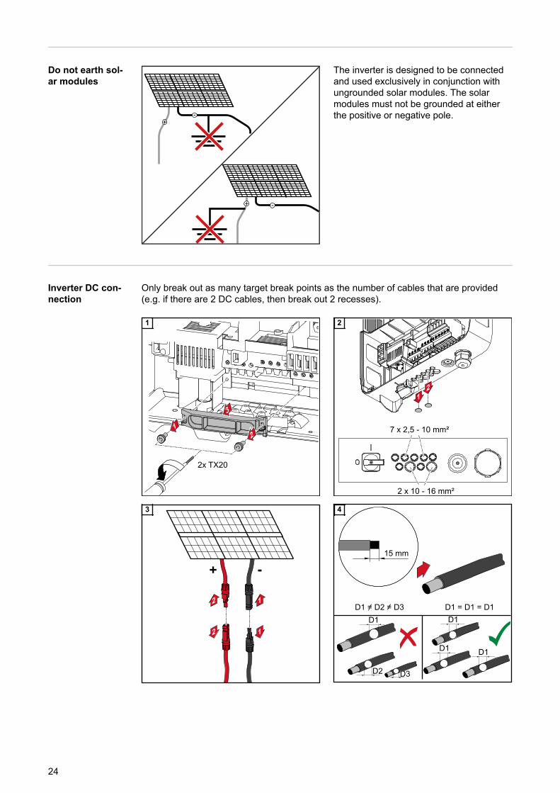
Do not earth sol-ar modules
The inverter is designed to be connectedand used exclusively in conjunction withungrounded solar modules. The solarmodules must not be grounded at eitherthe positive or negative pole.
Inverter DC con-nection
Only break out as many target break points as the number of cables that are provided(e.g. if there are 2 DC cables, then break out 2 recesses).
1 2
3 4
24

5 6
7 8
9
25
EN

Cable routing inthe DC area
If DC cables are laid over the shaft of theDC main switch or across the connectionblock of the DC main switch, they may bedamaged when the inverter is swung in orthey may even prevent the inverter frombeing swung in.
IMPORTANT! Do not lay DC cables overthe shaft of the DC main switch or acrossthe connection block of the DC mainswitch.
Multi MPP trackerinverters - Froni-us Primo 3.0 - 8.2
In the case of inverters with multiple MPP trackers, there are two independent DC inputs(MPP trackers) available. These can be connected to an unequal number of solar mod-ules.There are two terminals for DC+ available per MPP tracker. In total there are four termin-als for DC-.
Connecting two to four strings in multiple MPP tracker mode:
DC
-2
DC-
DC
-1
Primo 3.0 - 5.0:
max. 12 A per MPPT
Primo 5.0 AUS - 8.2:
max. 18 A per MPPT
PV 1
PV 2
1 21 2 3 41 2
DC+1 DC+2DC
+1
DC
+2
Connecting two solar module fields to an inverter withmultiple MPP trackers
Divide the strings between the two MPPtracker inputs (DC+1/DC+2). The DC- ter-minals can be used however you wish, asthey are internally connected.When starting for the first time, set MPPTRACKER 2 to "ON" (this can also bedone later in the Basic menu).
26

Single MPP tracker mode on an inverter with multiple MPP trackers:
Connecting multiple interconnected solar modulefields to an inverter with multiple MPP trackers usingone lead
If the strings are connected using a stringcollection box and only one bus is used forconnection to the inverter, the connectionDC+1 (pin 2) and DC+2 (pin 1) must bejumpered.The cable cross-section of the DC connec-tion lead and the jumpering must be thesame. Jumpering of the DC- terminal isnot necessary, as these terminals arejumpered internally.
When starting for the first time, set MPPTRACKER 2 to "OFF" (this can also bedone later in the Basic menu).
If the inverter with multiple MPP trackers isoperated in single MPP tracker mode, thecurrents from the connected DC leads aredivided evenly across both inputs.
Single MPP tracker mode with only one string on an inverter with multiple MPPtrackers:
Connecting only one string to an inverter with multipleMPP trackers
If only one string is used for connection tothe inverter, the connection DC+1 (pin 2)and DC+2 (pin 1) must be jumpered.The cable cross-section of the DC connec-tion lead and the jumpering must be thesame. Jumpering of the DC- terminal isnot necessary, as these terminals arejumpered internally.
When starting for the first time, set MPPTRACKER 2 to "OFF" (this can also bedone later in the Basic menu).
If the inverter with multiple MPP trackers isoperated in single MPP tracker mode, thecurrents from the connected DC leads aredivided evenly across both inputs.
27
EN

Data communication
Routing datacommunicationcables
IMPORTANT! Operating the inverter with one option card and two broken-out optioncard slots is not permitted.To cater for this eventuality, a suitable blanking cover (42,0405,2020) is available fromFronius as an option.
IMPORTANT! If data communication cables are wired into the inverter, observe the fol-lowing points:- Depending on the number and cross-section of the data communication cables that
are being introduced, take the relevant blanking plugs out of the sealing insert andinsert the data communication cables.
- The relevant blanking plugs must be inserted into the free openings on the sealinginsert.
1 2
3 4
Installing theDatamanager inthe inverter
WARNING!
Danger of residual voltage from capacitors.This may result in an electric shock.▶ Wait for the capacitors to discharge. The discharge time is five minutes.
28

WARNING!
Danger from inadequate ground conductor connection.This can result in serious injury and damage to property.▶ The housing screws provide a suitable ground conductor connection for earthing the
housing and must NOT be replaced by any other screws that do not provide a reli-able ground conductor connection.
IMPORTANT! Observe the ESD guidelines when handling option cards.
IMPORTANT! Only one Fronius Datamanager in master mode is permitted per FroniusSolar Net ring. Switch any other Fronius Datamanagers to slave mode or remove them.Seal off the unoccupied option card slot by replacing the cover (item number42,0405,2094); alternatively, use an inverter without a Fronius Datamanager (light ver-sion).
IMPORTANT! Only break out one openingfor the PC board when installing aDatamanager in the inverter.
1 2
29
EN
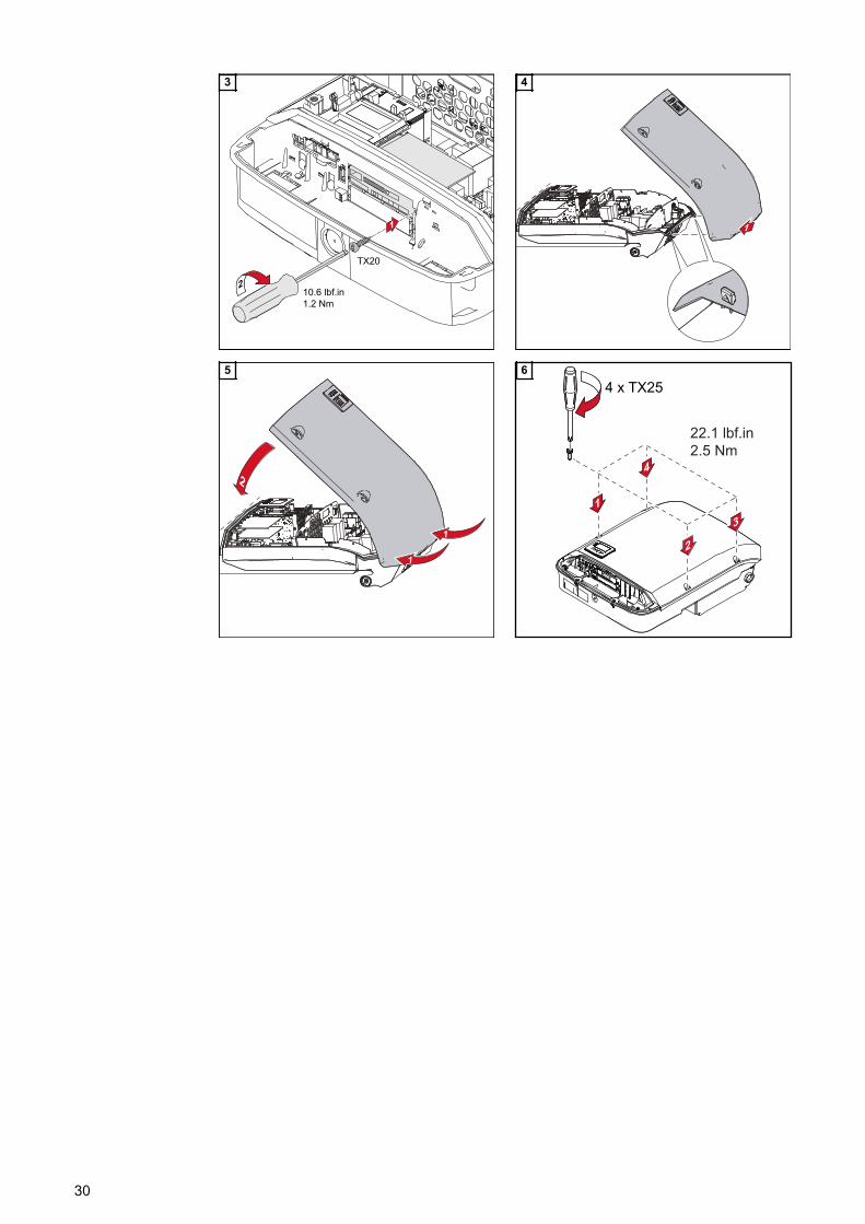
3 4
5 6
30

Australian Conduits
Tightly sealingthe conduits
Ensure that the conduits are tightly sealed.
Seal conduits NOTE!
Condensation within the conduits candamage the inverter or components ofthe photovoltaic systems.
To avoid undesirable air circulation andcondensation in the conduits:▶ Seal all conduits being used with a
permanently elastic sealant▶ Seal every incoming and outgoing
conduit▶ Seal both conduit ends.
Conduit
Conduit
AC~
Inside
Outside
DC=
4
3
2
Permanently elastic sealant
Seal all used conduits!
Seal every incoming and every outgoing conduit!
Seal both conduit ends!
1
Conduit
Inve
rte
r h
ou
sin
g
Co
nd
uit fittin
g
Pe
rma
ne
ntly e
lastic
se
ala
nt
11
1
31
EN

Attaching the inverter to the mounting bracket
Attaching the in-verter to themounting bracket
WARNING!
Danger from inadequate ground conductor connection.This can result in serious injury and damage to property.▶ The housing screws provide a suitable ground conductor connection for grounding
the housing and must NOT be replaced by any other screws that do not provide areliable ground conductor connection.
The side sections of the housing lid are designed to function as holding and carryinghandles.
Note! For safety reasons, the inverter is fitted with a latch that prevents the inverter frombeing swung into the mounting bracket unless the DC main switch is switched off.- Never attach the inverter to the mounting bracket or swing it in unless the DC main
switch is switched off.- Never use force to attach the inverter or swing it in.
The fastening screws in the data communication area of the inverter are used for secur-ing the inverter to the mounting bracket. Correctly tightened fastening screws are a pre-requisite if proper contact is to be established between the inverter and mounting brack-et.
CAUTION!
Danger due to incorrectly tightened fastening screws.This may result in arcs occurring when the inverter is in operation, which may lead to fire.▶ Always use the specified torque when tightening the fastening screws.
1 2
32

3 4
33
EN

Starting for the first time
Starting the in-verter for the firsttime
WARNING!
Danger due to incorrect operation and incorrectly performed work.This can result in serious injury and damage to property.▶ Only qualified personnel are authorised to commission your inverter and only within
the scope of the respective technical regulations.▶ Read the Installation and Operating Instructions before installing and commissioning
the equipment.
When starting the inverter for the first time, it is necessary to select various setup set-tings.
If setup is interrupted before it is complete, it can be restarted by means of an AC reset.An AC reset can be carried out by switching the automatic circuit breaker off and onagain.
The country setup can only be set when using the inverter for the first time. If the countrysetup needs to be changed at a later date, please contact your Technical Support team.
1
1 2
2
Select Country
1 2
50 HzInternational 50 Hz
3
34

* Country setup examples
The available country setups may change during a software update. Therefore, the following list may not ex-actly match the display on the inverter.
50Hz International 50 Hz60Hz International 60 HzAUS1 Australia AUS1 - AS/
NZS4777.2AUS2 Australia AUS2 - VICAUS3 Australia AUS3 - NSW
AusgridAUS4 Australia AUS4 - QLDAUS5 Australia AUS5 - SAAUS6 Australia AUS6 - WA - WPAUS7 Australia AUS7 - WA - HPAUA Australia Region A 2020AUB Australia Region B 2020AUC Australia Region C 2020BE Belgique / BelgiëBR2 Brasil: ≤ 6 kVABR3 Brasil: > 6 kVABR5 Brasil 240V: ≤ 6 kVABR6 Brasil 240V: > 6 kVACH Schweiz / Suisse /
Svizzera / SvizraCL ChileCY Κύπρος / Kıbrıs / CyprusCZ ČeskoDE1F Deutschland (≤ 4,6 kVA) -
konst. cosPhi(1)
DE1P Deutschland (≤ 4,6 kVA) -cosPhi(P) 0,95
DE2F Deutschland (> 4,6 kVA) -konst. cosPhi(1)
DE2P Deutschland (> 4,6 kVA) -cosPhi(P) 0,9
DE2U Deutschland (> 4,6 kVA) -Q(U)
DKA1 West Denmark - 125kWDU1 Dubai < 10 kWEE EstoniaES EspañaESA España - Type AESOS Territorios españoles en el
extranjero (Spanish Over-sea Islands)
EULV EU - low voltageEUMV EU - medium voltageFRLV FranceG98 Great Britain GB - G98G99 Great Britain GB - G99GB Great BritainGR ΕλλάδαHR HrvatskaHU MagyarországIE Éire / IrelandIN India
IT6 Italia ≤ 11,08 kVA 2019IT7 Italia > 11,08 kVA 2019JO98 Jordan G98JO99 Jordan G99LK Sri LankaMG50 Microgrid 50 HzMG60 Microgrid 60 HzNI98 Northern Ireland G98NI99 Northern Ireland G99NIE1 Northern Ireland <16ANIE2 Northern Ireland >16ANL NederlandNO NorgeNZ New ZealandNZ1 New Zealand 2020PL PolandPT PortugalRO RomâniaSA Saudi ArabiaSE SverigeSI SlovenijaSK SlovenskoTH M Thailand MEATH P Thailand PEATR TürkiyeUA УкраїнаZA South Africa / Suid-Afrika
CONFIG4
21
5
21
6
21
BASIC
MPP TRACKER 2
7
35
EN

8 9
36

Notes regarding software updates
Notes regardingsoftware updates
USB
+
3
54 4
1
2 2
If the inverter is supplied with a USB flashdrive, the inverter software must be up-dated as soon as the inverter has beencommissioned:
1 Plug the USB flash drive into the datacommunication area of the inverter
2 Open the Setup menu3 Select the "USB" menu item4 Select "Software Update"5 Update the software
37
EN

USB Stick as a Data Logger and for Updating In-verter Software
USB flash driveas a datalogger
If a USB flash drive is connected to the USB A socket it can function as a datalogger foran inverter.
The logging data stored on the USB flash drive can be viewed at any time in third-partyprogrammes (e.g Microsoft® Excel) using the CSV file logged at the same time.
Older versions of Excel (before Excel 2007) are limited to a maximum of 65,536 rows.
Data on the USBflash drive
If the USB flash drive is being used as a data logger, three files will be created automat-ically:
- FRONIUS.sys system file:This file stores information from the inverter that is irrelevant to the customer. Thefile must not be deleted separately. Only delete all of the files (sys, fld, csv) at onetime.
- DALO.fld log file:A log file for reading the data in the Fronius Solar.access software.
Further details on the Fronius Solar.access software can be found in the "DATCOMDetails" operating instructions at http://www.fronius.com
- DATA.csv log file:A log file for reading the data in a spreadsheet program (e.g.: Microsoft® Excel)
Data structure on the USB flash drive
(1) USB root directory(2) Fronius inverters (Fronius Galvo,
Fronius Symo, Fronius Primo orFronius Eco)
(3) Inverter number - can be set in theSetup menu under DATCOM
If there are several inverters with the sameinverter number, the three files will besaved in the same folder. A digit is addedto the file name as a suffix (e.g.:DALO_02.fld)
38
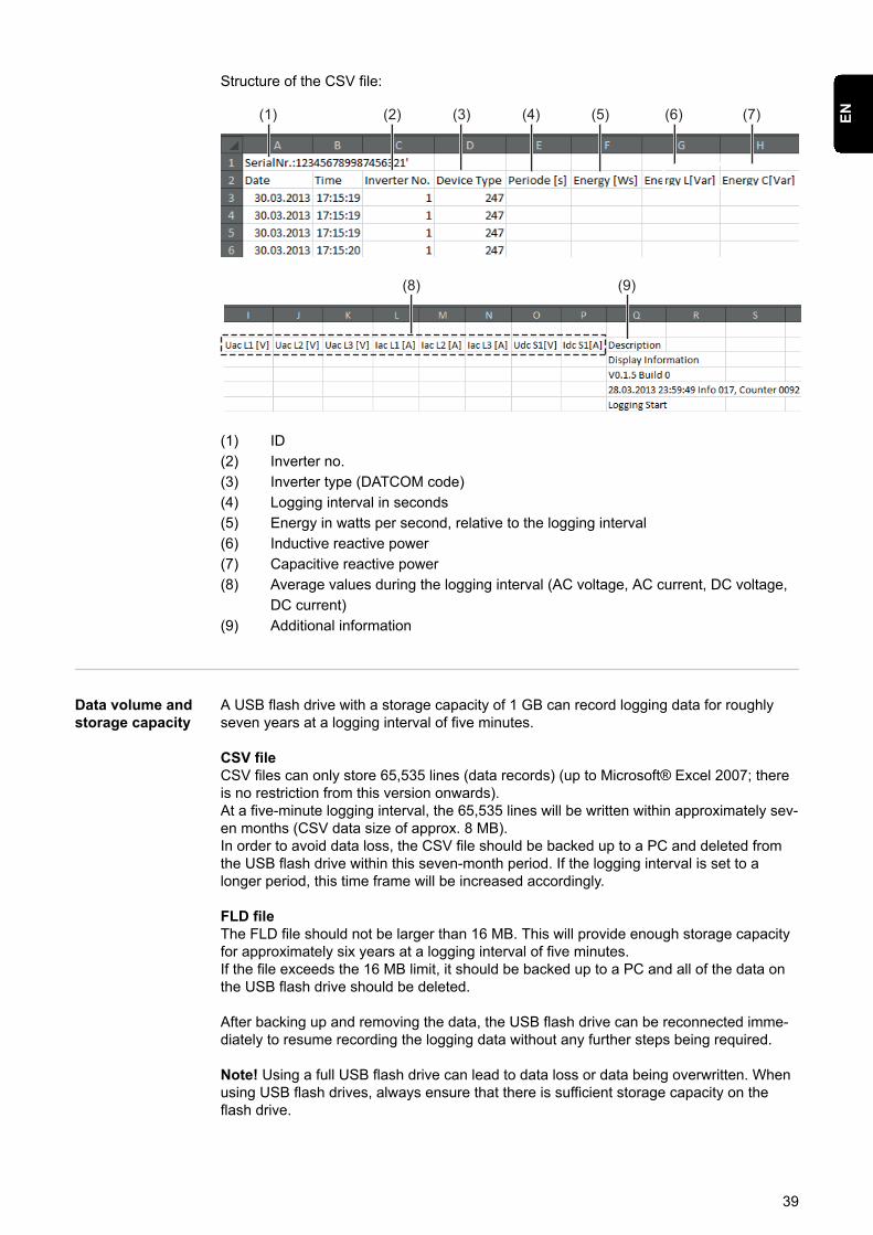
Structure of the CSV file:
(1) (2) (3) (4) (5) (6) (7)
(8) (9)
(1) ID(2) Inverter no.(3) Inverter type (DATCOM code)(4) Logging interval in seconds(5) Energy in watts per second, relative to the logging interval(6) Inductive reactive power(7) Capacitive reactive power(8) Average values during the logging interval (AC voltage, AC current, DC voltage,
DC current)(9) Additional information
Data volume andstorage capacity
A USB flash drive with a storage capacity of 1 GB can record logging data for roughlyseven years at a logging interval of five minutes.
CSV fileCSV files can only store 65,535 lines (data records) (up to Microsoft® Excel 2007; thereis no restriction from this version onwards).At a five-minute logging interval, the 65,535 lines will be written within approximately sev-en months (CSV data size of approx. 8 MB).In order to avoid data loss, the CSV file should be backed up to a PC and deleted fromthe USB flash drive within this seven-month period. If the logging interval is set to alonger period, this time frame will be increased accordingly.
FLD fileThe FLD file should not be larger than 16 MB. This will provide enough storage capacityfor approximately six years at a logging interval of five minutes.If the file exceeds the 16 MB limit, it should be backed up to a PC and all of the data onthe USB flash drive should be deleted.
After backing up and removing the data, the USB flash drive can be reconnected imme-diately to resume recording the logging data without any further steps being required.
Note! Using a full USB flash drive can lead to data loss or data being overwritten. Whenusing USB flash drives, always ensure that there is sufficient storage capacity on theflash drive.
39
EN
NOTE!
Risk of USB flash drive becoming full.This may result in data being lost or overwritten.▶ When using USB flash drives, always ensure that there is sufficient storage capacity
on the flash drive.
Buffer memory If the USB stick is unplugged (e.g. for data backup purposes), the logging data is writtento a buffer memory in the inverter.As soon as the USB stick is plugged in again, the data is copied automatically from thebuffer memory to the stick.
The buffer memory can store a maximum of six logging points. Data is only logged whilethe inverter is running (output greater than 0 W). The logging interval is permanently setat 30 minutes. Data can be recorded on the buffer memory for a three-hour time periodas a result.
When the buffer memory is full, the oldest data in the memory will be overwritten by thenext batch of data.
IMPORTANT! The buffer memory requires a permanent power supply.If there is a power failure while the inverter is in operation, all the data in the buffermemory will be lost. To avoid losing data during the night, the automatic night switch-offfacility must be deactivated (switch the "Night Mode" setup parameter to ON - see theDatamanager 2.0 Operating Instructions, section "Setting and displaying the menuitems", "Viewing and adjusting parameters in the DATCOM menu item").On the Fronius Eco or Fronius Symo 15.0-3 208, the buffer memory also functions withjust a DC supply.
Suitable USBflash drives
Due to the variety of USB flash drives available on the market, it cannot be guaranteedthat every USB flash drive will be detected by the inverter.
Fronius recommends that only certified, industry-grade USB flash drives are used (lookout for the USB-IF logo).
The inverter supports USB flash drives with the following file systems:- FAT12- FAT16- FAT32
Fronius recommends that the USB flash drive employed should only be used for record-ing logging data or updating the inverter software. The USB flash drives should not con-tain any other data.
40
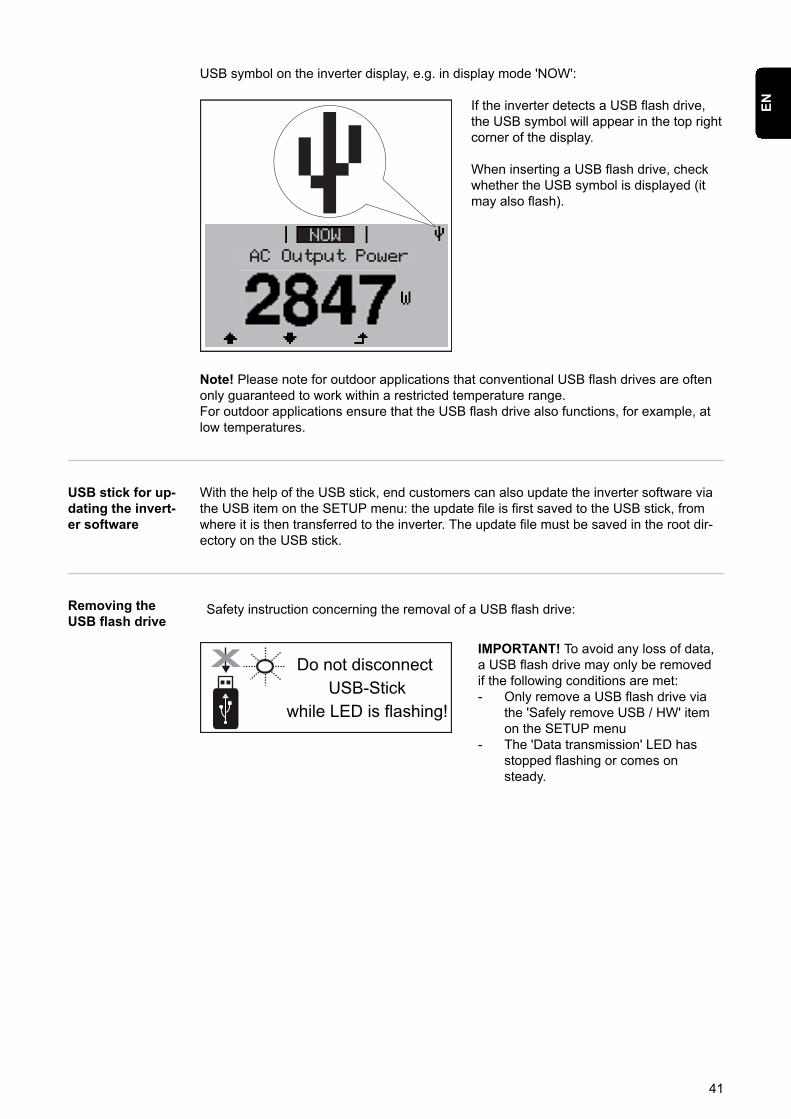
USB symbol on the inverter display, e.g. in display mode 'NOW':
AC Output Power
NOW
If the inverter detects a USB flash drive,the USB symbol will appear in the top rightcorner of the display.
When inserting a USB flash drive, checkwhether the USB symbol is displayed (itmay also flash).
Note! Please note for outdoor applications that conventional USB flash drives are oftenonly guaranteed to work within a restricted temperature range.For outdoor applications ensure that the USB flash drive also functions, for example, atlow temperatures.
USB stick for up-dating the invert-er software
With the help of the USB stick, end customers can also update the inverter software viathe USB item on the SETUP menu: the update file is first saved to the USB stick, fromwhere it is then transferred to the inverter. The update file must be saved in the root dir-ectory on the USB stick.
Removing theUSB flash drive
Safety instruction concerning the removal of a USB flash drive:
IMPORTANT! To avoid any loss of data,a USB flash drive may only be removedif the following conditions are met:- Only remove a USB flash drive via
the 'Safely remove USB / HW' itemon the SETUP menu
- The 'Data transmission' LED hasstopped flashing or comes onsteady.
41
EN

Notes regarding maintenance
Maintenance Note! When installed outdoors in a horizontal position: once a year, check that all screwjoints are tight!
Maintenance and servicing may only be carried out by Fronius-trained service techni-cians.
Cleaning Clean the inverter as required with a damp cloth.Do not use cleaning agents, abrasives solvents or similar to clean the inverter.
42

Serial Number Sticker for Customer Use
Serial numbersticker for cus-tomer use
The serial number of the inverter is locatedon the rating plate on the bottom of the in-verter.Depending on the installation position ofthe inverter, the serial number can be diffi-cult to access or read, e.g. if the inverterhas been installed in a dark or shadedarea.
Two serial number stickers are enclosedwith the inverter's installation instructions:* 57 x 20 mm** 67 x 20 mm
These can be affixed by the customer in avisible location of his choosing, e.g. on thefront of the inverter or on the Operating In-structions.
Application example:Serial number sticker on the Operating In-structions or on the front of the inverter
For Australia only:Affix the DRM Australia sticker in theDatamanager area.
43
EN

-
-