operating instructions is1 pn 2 04e - r. stahl · operating instructions is1 profinet v2.04 e -...
TRANSCRIPT

Operating Instructions
IS1 PROFINET V2.04 E - Technical alterations reserved 1
PROFINET interface description
Description of
PROFINET Interface
for
IS1 field stations

Operating Instructions
2 IS1 PROFINET V2.04 E - Technical alterations reserved -
PROFINET interface description
Content:
Historical development of the field bus technology at R. STAHL.......................................................................3
1 System overview ........................................................................................................................................ 42 Commissioning ........................................................................................................................................... 5
2.1 Overview ............................................................................................................................................. 52.2 System requirements .......................................................................................................................... 62.3 Engineering limits ................................................................................................................................ 62.4 Configuration of IS1 in the PROFINET controller .............................................................................. 72.5 Compatibility of new IS1+ IOM............................................................................................................ 82.6 Addressing the IS1 field station........................................................................................................... 9
2.6.1 BOOTP (Bootstrap Protocol) ....................................................................................................... 92.6.2 Address Conflict Detection (ACD)................................................................................................ 9
2.7 System start-up behavior .................................................................................................................. 102.8 PROFINET functions........................................................................................................................ 112.9 RIO Profile functions ......................................................................................................................... 11
2.9.1 Mode handling ........................................................................................................................... 122.9.2 Signal inversion.......................................................................................................................... 132.9.3 Scaling for AI and AO signals .................................................................................................... 132.9.4 Failsafe Function........................................................................................................................ 15
2.9.4.1 Behavior of the input signals in case of errors .................................................................. 152.9.4.2 Behavior of the output signals in case of errors................................................................ 15
2.10 Module revision mapping .................................................................................................................. 163 Data traffic ................................................................................................................................................ 16
3.1 Parameterization ............................................................................................................................... 163.1.1 CPU parameters ........................................................................................................................ 163.1.2 I/O module parameters .............................................................................................................. 17
3.1.2.1 AIM / AIMH 9461 ............................................................................................................... 173.1.2.2 AUMH 9468....................................................................................................................... 183.1.2.3 TIMR 9480........................................................................................................................ 193.1.2.4 TIM mV 9481.................................................................................................................... 213.1.2.5 TIM 9482 .......................................................................................................................... 223.1.2.6 DIM (9470/3x in compatible mode) ................................................................................ 243.1.2.7 DIOM 9470/3x (IS1+) ...................................................................................................... 253.1.2.8 AOM / AOMH 9466 .......................................................................................................... 263.1.2.9 DOM .................................................................................................................................. 27
3.2 Data word structure of the I/O modules ............................................................................................ 283.2.1 Analogue modules ..................................................................................................................... 28
3.2.1.1 Analog format with status according PI specification........................................................ 303.2.2 DIM, DIM+CF (9470/.. 9471/..) ............................................................................................ 353.2.3 DOM (9475/.., 9477/.., 9478/..) ................................................................................................. 41
3.3 HART variables ................................................................................................................................. 423.3.1 Data format ................................................................................................................................ 423.3.2 Selection of HART Variables ..................................................................................................... 42
3.4 HART Maintenance via IS1 DTM...................................................................................................... 433.5 Alarm- and diagnosis data ................................................................................................................ 443.6 Webserver in IS1 CPU ...................................................................................................................... 463.7 LED and LCD displays of the CPU ................................................................................................... 463.8 Online behavior of the IS1 field station. ............................................................................................ 463.9 Transmission time: ............................................................................................................................ 47
4 List of abbreviations:................................................................................................................................. 485 Release notes:.......................................................................................................................................... 496 Further reading ......................................................................................................................................... 497 Support address ....................................................................................................................................... 49

Operating Instructions
IS1 PROFINET V2.04 E - Technical alterations reserved 3
PROFINET interface description
The historical development of field bus technology at R. STAHL
In the year 1986 R. STAHL SCHALTGERÄTE GMBH brought the ICS MUX field bus system onto the marketas the first manufacturer to introduce an I.S. bus system world-wide for the input and output of signals in apotentially explosive atmosphere (Zone 1).This bus system consists of a master station installed in the control room as the interface partner for automa-tion units together with several completely explosion protected on-site stations or field stations (VOS) in-stalled directly in the field (Zone 1). The connection between the master station and field stations is made viaa single coaxial cable.
One of the many highlights of this I.S. bus system is that all the subassemblies of the system - even thepower packs – can be plugged or unplugged during operation without affecting the explosion protection. Thisbus system enabled R. STAHL to present users from the chemical, petrochemical or pharmaceutical indus-tries with an apparatus that can be installed in a potentially explosive atmosphere but that can be operatedlike an apparatus installed in the control room.This provided the ideal combination of the technical advantages of field bus technology (simple cabling struc-tures, powerful diagnostic options) with the resulting economical advantages (lower investment costs).
The VOS 200 system variant based on this bus system was introduced in 1993 as a supplement that in-cludes all the recognized advantages of the field bus system and was developed under two fundamentalaspects:
- Field bus solution for low signal traffic or decentralized automation units that do not require a masterstation.
- Standard solution to enable the simple implementation of future standardized bus systems.
The VOS 200 can be coupled to the most varied automation devices in either a redundant or non-redundantconfiguration as a point-to-point connection or (multi-drop) bus connection.The principle element of the VOS 200 system variant is the 9503 central unit (CU). This multi-processorsubassembly with dual port RAM takes over both the data traffic from and to the connected I/O subassem-blies as well as the upwards communication to distributed control systems or programmable logic controllers.The various interface options for the VOS 200 were expanded again in 1997 and supplemented to include aPROFIBUS DP connection.
A further step in optimizing this field bus technology was realized in 1999 with the development of the IS1Remote I/O system. Experience gained from previous systems was used to implement a new, more flexibleand more powerful product for the user as well as to provide a solution to all types of automation tasks.
IS1 has been extended in further steps by adding new modules, functions and communication protocols.
The IS1 system was extended in 2008 by SIL2 SAIMH modules which are communicating via PROFIsafeprotocol. IS1 is the first zone 1 RIO with PROFIsafe I/O modules worldwide.
The system extension IS1+ was introduced in 2012 containing mayor functional extensions and improve-ments together with a new design of the IOM modules.
The following section describes the system characteristics of the IS1 system when interfaced to an automa-tion system via PROFINET.

Operating Instructions
4
PROFINET interface description
1 System overview
As an off-the-shelf explosion protecteexplosive atmosphere (Zone 1 or Zoshows a Zone 1 solution.
The IS1 field station comes with an Eth
Configuration, parameter setting andvia GSDML description in the PROFIN
A webserver is integrated in the IS1 CP
EngineeringStation(IO Supervisor)
PLC/DCS PN Configuration+ Diagnosis
DCS / PLCPROFINET IOController
IS1 Field station
PROFINET I/O device
Cyclic I/OData + Status+ Configuration+ Parameter
IS1 CPU
TMIS1 IOM
DCS / PLCPROFINET IOController
Switch
ExZone1
Opticalfiber
Opticalfiber
Cu
. . . .
. . .I/O I/O
. . . .IS1 Field station
PROFINET I/O device
- Diagnosis- I/O-Data (slow)- I&M Data
- Configuration- Parameter
Browser
history tool
IS1 PROFINET
d unit, the IS1 field station can be instane 2). It can also be installed in the sa
ernet fiber optic connection and operate
diagnostics for the IS1 field station and iET Host configuration software.
Us which offers additional diagnostic fun
HART HART
V2.04
lledfe a
s as
ts I/O
ctio
r
P
n
s
WEBIS1 event
E - Technical alterations reserved -
directly in the potentiallyea. The diagram above
ROFINET I/O device.
modules are carried out
s.

Operating Instructions
IS1 PROFINET V2.04 E - Technical alterations reserved 5
PROFINET interface description
2 Commissioning
2.1 Overview
Planning of the complete PROFINET network:
- Which controller are in the network- Which PN I/O devices are in the network- Selection of network topology and network physics (switches, repeaters, glass fiber links ...)- Unique allocation of the IP addresses or device names in the network.
Perform the commissioning:
- Mechanical installation of the IS1 field station.- Mechanical installation of the PROFINET switches- Mechanical installation of all other bus users.
- Set up the bus connections.
- Set up the voltage supply of the IS1 field station.- Set up the voltage supply of the switches and other network components
- Set up the IP addresses and network device names using the configuration software of the controller.
- Configure the IS1 field stations with its I/O modules using the GSDML File and the configuration softwareof the controller.
- Programming of the controller
- Set the network into operation.
- Check Ethernet connection using:- LED´s on Ethernet Switches- Link LED´s of CPU on IS1 Fieldstation- „Ping“ command. Ping is responding in any CPU state.
- Check communication on the PROFINET using the following tools:- Diagnostics information from the controller and its the network management software- LEDs and text display on the CPU of the IS1 field station- Webserver in IS1 CPU
- Check I/O signals using the following tools:- Signal- and diagnosis information of the controller.- Optional use of the IS1 Event History Tool.
General Information regarding PROFINET see following PNO documents:
- PROFINET Design Guideline PNO Doc. 8.062- PROFINET Installation Guideline for Cabling and Assembly PNO Doc. 8.072- PROFINET Installation Guideline for Commissioning PNO Doc. 8.082

Operating Instructions
6 IS1 PROFINET V2.04 E - Technical alterations reserved -
PROFINET interface description
2.2 System requirements
Hardware requirements:
IS1 field station with CPU 9441/12-00-00 single socket 9492/12-11-31 or redundant socket 9492/12-11-32
Software requirements:
IOM IOM Firmware CPU Firmware GSDML
IS1 IOM from 02-00
from V51-05from
GSDML-V2.3-Stahl-RIO-20140206.xmlIS1+ IOM(94xx/3x….)
from 03-01
Siemens S7 Systems: STEP7 from V5.5 SP3 required !
2.3 Engineering limits
The general regulations according to the IS1 operating instructions apply to the engineering of an IS1 fieldstation.The limits and requirements on the PROFINET hosts and network components used must also be taken intoaccount during the engineering.

Operating Instructions
IS1 PROFINET V2.04 E - Technical alterations reserved 7
PROFINET interface description
2.4 Configuration of IS1 in the PROFINET controller
The documentation of the controller will describe the exact procedure for the configuration and parameteriza-tion of your master. As a result of the high degree of standardization of the PROFINET, the configuration andparameterization of the network and the devices is performed in a very similar fashion - even for the productsof different manufacturers. Device descriptions as GSDML files are available for the IS1 field stations. Thisfiles contain all the information important for the controller on the communication behavior, signals and pa-rameter of the IS1 field station. GSD files are read by the configuration software of the controller. The config-uration Software of the controller takes the information on the module types possible in an IS1 field stationfrom the GSD file.
The following table shows the supported I/O module types.
Type Number Short Name Submodule1 Submodule2 Module ID Generation
9460/12-08-11 AIM 8
8 AI
- IDM_AIM_03
IS1
9461/12-08-11 AIMH 8
8 HV
IDM_AIM_05
9461/12-08-21 AIMH 8 IDM_AIM_06
9461/15-08-12 AIMH 8 IDM_AIM_07
9465/12-08-11 AOM 8
8 AO
- IDM_AOM_09
9466/12-08-11 AOMH 88 HV
IDM_AOM_11
9466/15-08-12 AOMH 8 IDM_AOM_12
9468/3x-08-xx AUMH 8 8AI + 8AO 8 HV IS1+
9470/22-16-11 DIM 1616 DI 2 CF
IDM_DIM_13IS1
9470/25-16-12 DIM 16 IDM_DIM_14
9470/3x-16-xx DIOM 16 16 DI+16DO 8 CF IS1+
9471/15-16-12 DIM 16 16 DI 2 CF IDM_DIM_17
IS1
9475/12-04-11 DOM 4
4 DO
-
IDM_DOM_18
9475/12-04-21 DOM 4 IDM_DOM_19
9475/12-04-31 DOM 4 IDM_DOM_20
9475/12-08-41 DOM 8
8 DO
IDM_DOM_22
9475/12-08-51 DOM 8 IDM_DOM_23
9475/12-08-61 DOM 8 IDM_DOM_24
9475/22-04-21 DOM 4 4 DO IDM_DOM_36
9475/22-08-51 DOM 88 DO
IDM_DOM_32
9475/22-08-61 DOM 8 IDM_DOM_33
9475/3x-04-xx DOM 4 4 DO IDM_DOM_45IS1+
9475/3x-08-xx DOM 8 8 DO IDM_DOM_46
9477/12-08-12 DOM 8 60V Rel Z1 8 DO IDM_DOM_34
IS1
9477/12-06-12 DOM 6 250VRel Z1 6 DO IDM_DOM_35
9477/15-08-12 DOM 8 Rel Z28 DO
IDM_DOM_30
9478/22-08-51 DOMV8 OD IDM_DOM_42
9480/12-08-11 TIM 8 R 8 TI IDM_TIM_26
9481/12-08-11 TIM 8 mV 8 TI IDM_TIM_28
9482/3x-08-xx TIM 8 8 TI IS1+

Operating Instructions
8 IS1 PROFINET V2.04 E - Technical alterations reserved -
PROFINET interface description
2.5 Compatibility of new IS1+ IOM
New IS1+ IOM can be used in existing plants for compatible replacement of previous IS1 IOM.No change of GSD File or configuration is required in such case.The IS1+ IOM switch to a compatible mode in case of detection of an allowed configuration of the previousIOM.If new features of the IS1+ IOM shall be used which are not supported by the previous IOM new configura-tion according type number of the IS1+ IOM is required.
Overview of compatible IOM:
IS1 IOM compatible IS1+ IOM Remark
9460/12-08-11 AIM 8
9468/32-08-11 AUMH Zone 1
9468/33-08-10 AUMH Zone 2
-
9461/12-08-11AIMH 8
-
9461/12-08-21 9164 additionally required
9465/12-08-11 AOM 8 -
9466/12-08-11 AOMH 8 -
9470/12-16-11DIM 16 9470/32-16-11 DIOM Zone 1
9470/33-16-10 DIOM Zone 2
-
9470/22-16-11 -
9475/12-08-41 DOM 8 for low power valves
9475/12-04-11
DOM 4
9475/32-04-12 DOM Zone 1 -
9475/12-04-21 9475/32-04-22 DOM Zone 1 -
9475/12-04-31 - discontinued
9475/12-08-41
DOM 8
see above 9470/3x DIOM -
9475/12-08-519475/32-08-52 DOM Zone 19475/33-08-50 DOM Zone 2
-
9475/12-08-619475/32-08-62 DOM Zone 19475/33-08-60 DOM Zone 2
-
9475/22-04-21 DOM 4 OD 9475/32-04-22 DOM Zone 1 -
9475/22-08-51DOM 8 OD
9475/32-08-52 DOM Zone 1 -
9475/22-08-61 9475/32-08-62 DOM Zone 1 -
9480/12-08-11 TIM R9482/3x-08-xx 8TIM
-
9481/12-08-11 TIM mV -

Operating Instructions
IS1 PROFINET V2.04 E - Technical alterations reserved 9
PROFINET interface description
2.6 Addressing the IS1 field station
The following information is required to address an IS1 field station: Devicename (Allocation via PN IO-Supervisor) IP address (Usually done automatically by PN IO-Supervisor) SubNet mask ?? optional: Gateway (only necessary for communication via routers)
The addresses for an IS1 field station can be set via: Preferred during operation of PROFINET
o from Network configuration software of the controller (PN IO-Supervisor)
Optional possible (e.g. for operation without PN IO-Supervisor during commissioning)o Buttons and display on IS1 CPU.o IS1 webservero BOOTP Server
Attention! The Devicenames and IP addresses must be unique in the network. (see ACD)
2.6.1 BOOTP (Bootstrap Protocol)BOOTP is not required for PROFINET I/O and therefore deactivated.It can be activated optionally by setting start_with_bootp=1 in the file b:/settings.ini within the IS1 CPU.
IS1 supports the setting of IP Address via BOOTP Protocol according RFC951.The IS1 Fieldstation must be configured in a BOOTP server which must be present on the Ethernet network. TheIP-Address for the IS1 CPU must be allocated to its MAC-Address.
After power on the IS1 CPU checks the availability of a BOOTP server on the network and receives its IPaddress from this BOOTP server. The IP address is stored non volatile in the socket of the IS1 CPU.
If no BOOTP server is detected or the IS1 CPU is not configured in the BOOTP server then the IS1 CPU usethe previous non volatile stored IP address.
2.6.2 Address Conflict Detection (ACD)
Double IP addresses in one Ethernet Network can lead to unforeseeable behavior. To detect and to handlesuch situations ACD according RFC5227 was defined. IS1 is supporting this feature.
Address conflict during startup:After power on start up the IS1 CPU checks for other devices with the same IP address on the network.In case of conflict the IS1 CPU stops further standard communication on Ethernet and checks in the back-ground if the conflict is still present.
Address conflict during operation:Depending on the behavior of the conflict partner the IS1 CPU or the conflict partner can withdraw fromcommunication on Ethernet network.
Operating Instructions
10 IS1 PROFINET V2.04 E - Technical alterations reserved -
PROFINET interface description
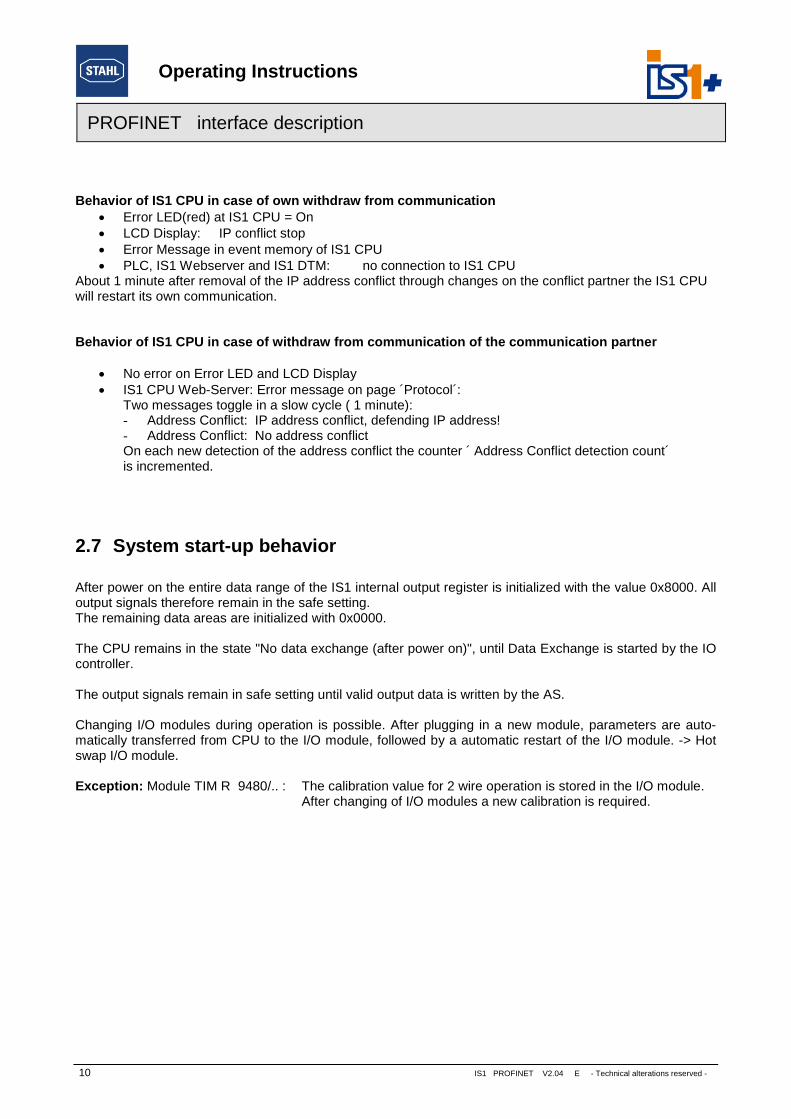
Behavior of IS1 CPU in case of own withdraw from communication Error LED(red) at IS1 CPU = On LCD Display: IP conflict stop Error Message in event memory of IS1 CPU PLC, IS1 Webserver and IS1 DTM: no connection to IS1 CPU
About 1 minute after removal of the IP address conflict through changes on the conflict partner the IS1 CPUwill restart its own communication.
Behavior of IS1 CPU in case of withdraw from communication of the communication partner
No error on Error LED and LCD Display IS1 CPU Web-Server: Error message on page ´Protocol´:
Two messages toggle in a slow cycle ( 1 minute):- Address Conflict: IP address conflict, defending IP address!- Address Conflict: No address conflictOn each new detection of the address conflict the counter ´ Address Conflict detection count´is incremented.
2.7 System start-up behavior
After power on the entire data range of the IS1 internal output register is initialized with the value 0x8000. Alloutput signals therefore remain in the safe setting.The remaining data areas are initialized with 0x0000.
The CPU remains in the state "No data exchange (after power on)", until Data Exchange is started by the IOcontroller.
The output signals remain in safe setting until valid output data is written by the AS.
Changing I/O modules during operation is possible. After plugging in a new module, parameters are auto-matically transferred from CPU to the I/O module, followed by a automatic restart of the I/O module. -> Hotswap I/O module.
Exception: Module TIM R 9480/.. : The calibration value for 2 wire operation is stored in the I/O module.After changing of I/O modules a new calibration is required.
Operating Instructions
IS1 PROFINET V2.04 E - Technical alterations reserved 11
PROFINET interface description
2.8 PROFINET functions
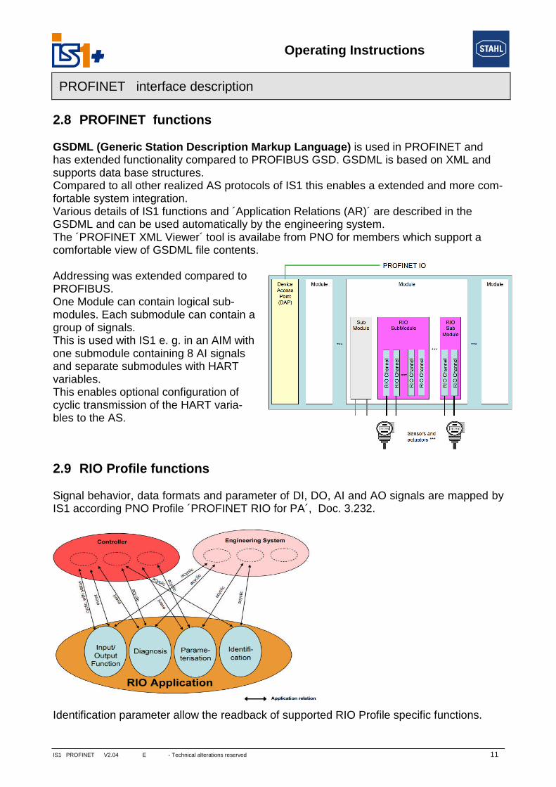
GSDML (Generic Station Description Markup Language) is used in PROFINET andhas extended functionality compared to PROFIBUS GSD. GSDML is based on XML andsupports data base structures.Compared to all other realized AS protocols of IS1 this enables a extended and more com-fortable system integration.Various details of IS1 functions and ´Application Relations (AR)´ are described in theGSDML and can be used automatically by the engineering system.The ´PROFINET XML Viewer´ tool is availabe from PNO for members which support acomfortable view of GSDML file contents.
Addressing was extended compared toPROFIBUS.One Module can contain logical sub-modules. Each submodule can contain agroup of signals.This is used with IS1 e. g. in an AIM withone submodule containing 8 AI signalsand separate submodules with HARTvariables.This enables optional configuration ofcyclic transmission of the HART varia-bles to the AS.
2.9 RIO Profile functions
Signal behavior, data formats and parameter of DI, DO, AI and AO signals are mapped byIS1 according PNO Profile ´PROFINET RIO for PA´, Doc. 3.232.
Identification parameter allow the readback of supported RIO Profile specific functions.

Operating Instructions
12
PROFINET interface description
Device functions are mapped to Transducer- and Function Blocks and are partially simmi-lar to definitions of the PROFIBUS PA profile.
Example: AI
2.9.1 Mode ha
Mode handlingfor all signal typ
Name
AUTO
MANUAL
O/S (out of servic
*1) Writing FB Parprepared in IS1 bu
FailsafeFunction
ModeHandlingFunction
Function Block Diagnosis
Function BlockIdentification
Function BlockParameters
TransducerFunction
Parameter-ization
Identi-fication
Diagnosis
Transducer Block Diagnosis
Transducer BlockIdentification
Transducer BlockParameters
Parameter-ization
Identi-fication
Diagnosis
Sensor signalorstandard signal(4-20 mA ….)
PVPhys. value
OutPhys. value
Scaling
IS1 PROFINET V2.04 E - Technical alterations reserved -
ndling
is availablees:
Description
In operation. Signal is available and updated cyclically
Signal with Status can be written by the parameter ´Out´. *1)
e) Signal is out of service. No diagnosis alarms. Status = bad, device passivated
ameters according RIO for PA profile like e. g. Parameter ´Out´ via acyclic data blocks ist not supported by actual tools.
Input Function BlockTransducer Block with status with status

Operating Instructions
IS1 PROFINET V2.04 E - Technical alterations reserved 13
PROFINET interface description
2.9.2 Signal inversion
Inversion (for DI only):
2.9.3 Scaling for AI and AO signals
Conversion of standard signals (e.g. 4 – 20 mA)to signals with physical unit (e.g. m
3/h) is supported.
Free scaling:For free scaling with use of the parameter MIN_VALUE and MAX_VALUE the parameter UNIT_CODE =1995 ´ Textual Unit definition ´ must be set.In this case any Unit string can be assigned as ASCII Text to parameter UNIT_TEXT which can be read anddisplayed by the AS. The settings of the parameter SIGNAL_TYPE respectively SENSOR_TYPE effect themeasuring range ( 0% and 100%) where the scaling is based on.
In all other cases of parameter UNIT_CODE the scaling factors are set internaly of the IS1 CPU and thevalue is scaled to the selected unit. The selected unit can be read and displayed by the AS using the param-eter UNIT_CODE. Settings of the parameter MIN_VALUE, MAX_VALUE and UNIT_TEXT have no effect inthis case.
Name Description Type
MIN_VALUE The value in engineering units at 0% of the input signal (e.g. 4mA, 0V,…).Float
MAX_VALUE The value in engineering units at 100% of the input signal (e.g. 20mA, 10V, ..)
UNIT_CODE A code representing the Engineering Unit. INT16
UNIT_TEXT Any Unit string. In AS used if UNIT_CODE = 1995 (Textual Unit definition) only. String 32
SIGNAL_VALUE_IN The digital representation of the physical value with status information INT16
SCALED_VALUEThe digital representation of the scaled physical value with status infor-mation. The status information is generated by the algorithm.
Float+Status
SIGNAL_MINthe upper (100%) and lower (0%) values of measuring range of the standardsignal, depending on the type of the signal (SIGNAL_TYPE orSENSOR_TYPE).
For example, for a 4..20mA signal SIGNAL_MIN is 4 andSIGNAL_MAX is 20. See Data word structure of the I/O modules
-SIGNAL_MAX
Scaling
Transducer Block Diagnosis
MIN_VALUEMAX_VALUEUNIT_CODE
Parameteri-zation
Diagnosis
SIGNAL_VALUE_IN SCALED_VALUE

Operating Instructions
14 IS1 PROFINET V2.04 E - Technical alterations reserved -
PROFINET interface description
Scaling function:
If Scaling is used for AO signals, the scaling function is used inversely.
Examples for common UNIT Codes:
UNIT UNIT_CODE Hint
K 1000
-
°C 1001
°F 1002
Hz 1077
kHz 1081
bar 1137
mbar 1138
mA 1211
V 1240
Ω 1281
kΩ 1284
Textual Unitdefinition
1995
Any Unit can be allocated as ASCII Text in parameter UNIT_TEXT. In ASthis string is used if UNIT_CODE = 1995 (Textual Unit definition) only.Parameter MIN_VALUE und MAX_VALUE shall be used for definition ofthe conversion factor in this case. The use of ´Visible exchange format´ ´(PNO Doc. 3.512 or ISO/IEC 10646) is recommended.
Examples for Visible exchange format:m3/min = m**3/minl/s = l/s°C = C°F = F
Ω = O kΩ = kO
°C = C

Operating Instructions
IS1 PROFINET V2.04 E - Technical alterations reserved 15
PROFINET interface description
2.9.4 Failsafe Function
Parameter Name Selection
FAILSAFE_TYPE
AI AO DI / DO
freeze (USE_LAST_VALID_VALUE)
-10%,0%,
100%,
-10% ( for live Zero only)
0%,100%,110%
01
FAILSAFE_TIMEIS1 global CPU parameter:
Failsafe time output modules (x100 ms)
2.9.4.1 Behavior of the input signals in case of errors
If no valid signal value can be formed as a result of a malfunction (short circuit, open circuit, defective subas-sembly...), an alarm message is transmitted to the AS and diagnostics information is created which can beread via the AS or the engineering system. Despite the outstanding malfunction, cyclic data including signalstatus information continues to be transmitted to the AS.The input signals adopt the safe state accordingthe settings of Failsafe Function and the error is indicated insignal status.
2.9.4.2 Behavior of the output signals in case of errors
Communication error between the host and IS1 field station:The cyclic data traffic between the PROFINET host and IS1 is checked in the IS1 CPU.In case of communication loss to the PROFINET controller the outputs adopt the safe state accordingthesettings of Failsafe Function.
Communication error between the CPU and output module:There are watchdog circuits on the output modules that monitor the data transmission between the CPU andthe output modules. If an output module does not receive any valid data for more than TMod (Parameter´Failsafe time output modules´), the outputs adopt the safe state accordingthe settings of Failsafe Function.TMod can be set as CPM parameter ´Failsafe time output modules´ global for each IS1 fieldstation in therange 100 ms to 25.5 sec. (default value: 100 ms).
Signal statusIf a output signal with signal status unequal = OK is written from the AS, the output adopt the safe stateaccordingthe settings of Failsafe Function.

Operating Instructions
16 IS1 PROFINET V2.04 E - Technical alterations reserved -
PROFINET interface description
2.10 Module revision mapping
STAHL PNExample
STAHL PN
HW- Rev. Rev. A, B, C …. 1, 2, 3, …. Rev. G 7
FW- Rev. xx-yy V xx.yy.zz 02-40 V2.4.0
3 Data traffic
3.1 Parameterization
3.1.1 CPU parameters
Parameter Group Parameter Default value Value range / selection
CPU parameter Failsafe time output modules (x 100 ms) 1 Unsigned 8 (1 - 255)
Operating Instructions
IS1 PROFINET V2.04 E - Technical alterations reserved 17
PROFINET interface description
3.1.2 I/O module parameters
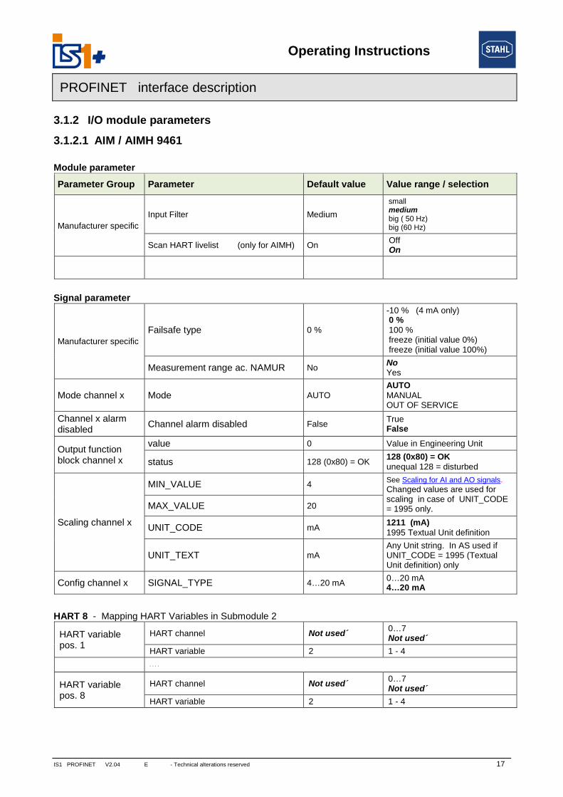
3.1.2.1 AIM / AIMH 9461
Module parameter
Parameter Group Parameter Default value Value range / selection
Manufacturer specific
Input Filter Medium
smallmediumbig ( 50 Hz)big (60 Hz)
Scan HART livelist (only for AIMH) OnOffOn
Module alarm Module alarm Alarms enabledAlarms enabledDiagnosis alarms disabled
Signal parameter
Manufacturer specific
Failsafe type 0 %
-10 % (4 mA only)0 %100 %freeze (initial value 0%)freeze (initial value 100%)
Measurement range ac. NAMUR NoNoYes
Mode channel x Mode AUTOAUTOMANUALOUT OF SERVICE
Channel x alarmdisabled
Channel alarm disabled FalseTrueFalse
Output functionblock channel x
value 0 Value in Engineering Unit
status 128 (0x80) = OK128 (0x80) = OKunequal 128 = disturbed
Scaling channel x
MIN_VALUE 4See Scaling for AI and AO signals.
Changed values are used forscaling in case of UNIT_CODE= 1995 only.MAX_VALUE 20
UNIT_CODE mA1211 (mA)1995 Textual Unit definition
UNIT_TEXT mAAny Unit string. In AS used ifUNIT_CODE = 1995 (TextualUnit definition) only
Config channel x SIGNAL_TYPE 4…20 mA0…20 mA4…20 mA
HART 8 - Mapping HART Variables in Submodule 2
HART variablepos. 1
HART channel Not used´0…7Not used´
HART variable 2 1 - 4
. . . .
HART variablepos. 8
HART channel Not used´0…7Not used´
HART variable 2 1 - 4

Operating Instructions
18 IS1 PROFINET V2.04 E - Technical alterations reserved -
PROFINET interface description
3.1.2.2 AUMH 9468
Module parameter
Parameter Group Parameter Default value Value range / selection
Manufacturer specific
Input Filter Medium
SmallMediumBig ( 50 Hz)Big (60 Hz)
Scan HART livelist (only for AIMH) OnOffOn
Module alarm Module alarm Alarms enabledAlarms enabledDiagnosis alarms disabled
Signal parameter
Manufacturer specific
Failsafe type 0 %
-10 % (4 mA only)0 %100 %freeze (initial value 0%)freeze (initial value 100%)
Measurement range ac. NAMUR *1) NoNoYes
I/O type Analog InputInputOutput
Mode channel x Mode AUTOAUTOMANUALOUT OF SERVICE
Channel x alarmdisabled
Channel alarm disabled FalseTrueFalse
Output functionblock channel x
value 0 Value in Engineering Unit
status 128 (0x80) = OK128 (0x80) = OK< 128 = disturbed
Scaling channel x
MIN_VALUE 4See Scaling for AI and AO signals.
Changed values are used forscaling in case of UNIT_CODE= 1995 only.MAX_VALUE 20
UNIT_CODE mA1211 (mA)1995 Textual Unit definition
UNIT_TEXT mAAny Unit string. In AS used ifUNIT_CODE = 1995 (TextualUnit definition) only
Config channel x SIGNAL_TYPE 4…20 mA0…20 mA4…20 mA
*1) The parameters ´ Measurement range ac. NAMUR ´ are valid only for Input Signals !The parameters are visible for all switchable AI/AO Signals but are without effect for the AO signals.
HART 8 - Mapping HART Variables in Submodule 2
HART variablepos. 1
HART channel Not used´0…7Not used´
HART variable 2 1 - 4
. . . .
HART variablepos. 8
HART channel Not used´0…7Not used´
HART variable 2 1 - 4

Operating Instructions
IS1 PROFINET V2.04 E - Technical alterations reserved 19
PROFINET interface description
3.1.2.3 TIMR 9480
Module parameter
Parameter Group Parameter Default value Value range / selection
Manufacturer specific
Input Filter 50 Hz50 Hz60 HzOff (not recommended)
Operation mode 8 inputs8 inputs2 inputs
Module alarm Module alarm Alarms enabledAlarms enabledDiagnosis alarms disabled
Signal parameter
Manufacturer specific
Failsafe type freeze freeze (initialization value 0%)
Connection4 wire measure(Pot in Ohm)
2 wire measure (Pot in Ohm)3 wire measure (Pot in %)4 wire measure (Pot in Ohm)
Sensor type Pt100
Pt100Pt500Pt1000Ni100Ni500Ni1000Resistance (Pot) 10kResistance (Pot) 5kResistance (Pot) 2k5Resistance (Pot) 500RPt100 GOSTM50 GOST from Fw. V02-04M100 GOSTCu53 GOSTPt46 GOST from Fw. V02-05Pt50 GOST
Mode channel x Mode AUTOAUTOMANUALOUT OF SERVICE
Channel x alarmdisabled
Channel alarm disabled FalseTrueFalse
Output functionblock channel x
value 0 Value in Engineering Unit
status 128 (0x80) = OK128 (0x80) = OKunequal 128 = disturbed

Operating Instructions
20 IS1 PROFINET V2.04 E - Technical alterations reserved -
PROFINET interface description
Parameter Group ParameterDefaultvalue
Value range / selection
Scaling channel x
MIN_VALUE -200 See Scaling for AI and AO signals.
Changed values are used for scaling incase of UNIT_CODE = 1995 only.MAX_VALUE 850
UNIT_CODE *1)
Unit allowed Type
°C1001 °C1002 °F
all temperaturesensors
Ω1281 Ω 1284 kΩ
Resistance (Pot)2 wire or 4 wire m.(Pot in Ohm)
% 1342 %Resistance (Pot)3 wire measure(Pot in %)
-1995 TextualUnit definition
All types except temp.sensors
UNIT_TEXT mAAny Unit string. In AS used ifUNIT_CODE = 1995 (Textual Unitdefinition) only
*1) Note: Allowed unit codes depend on settings of parameter ´Sensor Type´ and in case of Resistance(Pot) measurement additional on parameter ´Connection´. The selected unit code will be ignored in case ofnot allowed combinations, and the default unit with default scaling for the selected Sensor Type will be used.

Operating Instructions
IS1 PROFINET V2.04 E - Technical alterations reserved 21
PROFINET interface description
3.1.2.4 TIM mV 9481
Module parameter
Parameter Group Parameter Default value Value range / selection
Manufacturer specific Input Filter 50 Hz50 Hz60 Hz
Module alarm Module alarm Alarms enabledAlarms enabledDiagnosis alarms disabled
Signal parameter
Manufacturer specific
Failsafe type freeze freeze (initialization value 0%)
Input signal BalancedBalancedUnbalanced
Sensor type THC Type K
0…100 mVTHC Type BTHC Type ETHC Type JTHC Type KTHC Type NTHC Type RTHC Type STHC Type TTHC Type LTHC Type UTHC Type XK
Mode channel x Mode AUTOAUTOMANUALOUT OF SERVICE
Channel x alarmdisabled
Channel alarm disabled FalseTrueFalse
Output functionblock channel x
value 0 Value in Engineering Unit
status 128 (0x80) = OK128 (0x80) = OKunequal 128 = disturbed
Scaling channel x
MIN_VALUE -200 See Scaling for AI and AO signals.
Changed values are used forscaling in case of UNIT_CODE =1995 only.MAX_VALUE 1370
UNIT_CODE °C
Unit allowed Type
1001 °C1002 °F
all THCsensors
1243 mV1995 textualUnit definition
0…100 mV
UNIT_TEXT CAny Unit string. In AS used ifUNIT_CODE = 1995 (Textual Unitdefinition) only

Operating Instructions
22 IS1 PROFINET V2.04 E - Technical alterations reserved -
PROFINET interface description
3.1.2.5 TIM 9482
Module parameter
Parameter Group Parameter Default value Value range / selection
ManufacturerspecificModule alarm
Operation mode8 channelprecise
8 channel precise4 channel fast
TC cold junction Modulealarm InternalnabledInternalExternal 3 wire nosis alarms dibled
Type TC external cold junction I6-I7 PT100PT100PT1000PT100 GOST
Signal parameter
Manufacturer specific
Failsafe type freeze freeze (initialization value 0%)
Connection4 wire measure(Pot in Ohm)
2 wire measure (Pot in Ohm)3 wire measure (Pot in %)4 wire measure (Pot in Ohm)4 wire measure (Pot in %)
Sensor type Pt100
Pt100Pt500Pt1000Ni100Ni500Ni1000Resistance (Pot) 10kResistance (Pot) 5kResistance (Pot) 2k5Resistance (Pot) 500RPt100 GOSTM50 GOSTM100 GOSTCu53 GOSTPt46 GOSTPt50 GOST0…100 mVTHC Type BTHC Type ETHC Type JTHC Type KTHC Type NTHC Type RTHC Type STHC Type TTHC Type LTHC Type UTHC Type XK (L)
Mode channel x Mode AUTOAUTOMANUALOUT OF SERVICE
Channel x alarmdisabled
Channel alarm disabled FalseTrueFalse
Output functionblock channel x
value 0 Value in Engineering Unit
status 128 (0x80) = OK128 (0x80) = OKunequal 128 = disturbed

Operating Instructions
IS1 PROFINET V2.04 E - Technical alterations reserved 23
PROFINET interface description
Parameter Group ParameterDefaultvalue
Value range / selection
Scaling channel x
MIN_VALUE -200 See Scaling for AI and AO signals.
Changed values are used for scaling incase of UNIT_CODE = 1995 only.MAX_VALUE 1370
UNIT_CODE *1)
Unit allowed Type
°C1001 °C1002 °F
all THC andtemp. sensors
mV 1243 mV 0…100 mV,
Ω1281 Ω 1284 kΩ
Resistance (Pot)2 wire or 4 wire measure(Pot in Ohm)
% 1342 %Resistance (Pot)3 wire or 4 wire measure(Pot in %)
-1995textual Unitdefinition
All types except THCand temp. sensors
UNIT_TEXT CAny Unit string. In AS used ifUNIT_CODE = 1995(Textual Unit definition) only
*1) Note: Allowed unit codes depend on settings of parameter ´Sensor Type´ and in case of Resistance(Pot) measurement additional on parameter ´Connection´. The selected unit code will be ignored in case ofnot allowed combinations, and the default unit with default scaling for the selected Sensor Type will be used.

Operating Instructions
24 IS1 PROFINET V2.04 E - Technical alterations reserved -
PROFINET interface description
3.1.2.6 DIM (9470/3x in compatible mode)
Module parameter
Parameter Group Parameter Default value Value range / selection
Module alarm Module alarm Alarms enabledAlarms enabledDiagnosis alarms disabled
Signal parameter
Manufacturer specific
Failsafe type 0 %
01freeze (initial value 0)freeze (initial value 1)
Pulse extension 0 s
0 s0.6 s1.2 s2.4 s
Mode channel x Mode AUTOAUTOMANUALOUT OF SERVICE
Channel x alarmdisabled
Channel alarm disabled FalseTrueFalse
Output functionblock channel x
value 0 0, 1
status 32 (0x20) = OK32 (0x20) = OKunequal 32 = disturbed
Invert channel x Inversion FalseTrueFalse
Counter Frequency 2 chan - Parameter Submodule 2
Count./Freq. con-fig. chan. 14
Operation modeFreq. 0-1 kHz/ DI
CounterFreq. 0-1 kHz / DIFreq. 0-20 kHz gate 50 ms / DIFreq. 0-20 kHz gate 200 ms / DIFreq. 0-20 kHz gate 1 s / DI
Counting event Positive edgePositive edgeNegative edge
Count./Freq. con-fig. chan. 15
s. a.
Scalingchannel 14
MIN_VALUE 0 See Scaling for AI and AO signals.
Changed values are used forscaling in case of UNIT_CODE =1995 only.MAX_VALUE 1000
UNIT_CODE Hz
Unit allowed mode
1077 Hz1081 kHz1995 textualUnit definition
CounterFrequency
UNIT_TEXT HzAny Unit string. In AS used ifUNIT_CODE = 1995 (Textual Unitdefinition) only
Scalingchannel 15
s. a.

Operating Instructions
IS1 PROFINET V2.04 E - Technical alterations reserved 25
PROFINET interface description
3.1.2.7 DIOM 9470/3x (IS1+)
Module parameter
Parameter Group Parameter Default value Value range / selection
Module alarm Module alarm Alarms enabledAlarms enabledDiagnosis alarms disabled
Signal / Signal pair parameter
Manufacturer specific
Failsafe type 0 %
01freeze (initial value 0)freeze (initial value 1)
Pulse extension / Filter chan. x, x+1 0 s
0 s / Off0,6 s / Small1,2 s / Medium2,4 s / Large
I/O type channel x, x+1 InputInputOutput
Mode channel x Mode AUTOAUTOMANUALOUT OF SERVICE
Channel x alarmdisabled
Channel alarm disabled FalseTrueFalse
Output functionblock channel x
value 0 0, 1
status 32 (0x20) = OK32 (0x20) = OK< 32 = disturbed
Invert chann.x, x+1 Inversion (for DI signals only) FalseTrueFalse
Counter 8 chan - Parameter Submodule 2
Count./Freq.config.
chan. 8+9chan. 10+11chan. 12+13chan. 14+15
Operation modeFreq. 1 Hz - 3 kHz(0,05Hz/Bit)
0 = Counter 16 Bit1 = Freq. 0,1 - 600 Hz (0,01Hz/Bit)2 = Freq. 1 Hz - 3 kHz (0,05Hz/Bit)3 = Freq. 1 Hz - 20 kHz (0,5Hz/Bit)4 = Up/Down Counter 16 Bit5 = Up/Down Counter 32 Bit6 = Freq. 1 Hz - 20 kHz with direction
Counting event Positive edgePositive edgeNegative edge
Scaling
chan. 8chan. 9...chan. 14chan. 15
MIN_VALUE 0See Scaling for AI and AO signals.
Changed values are used forscaling in case of UNIT_CODE =1995 only.MAX_VALUE 2000
UNIT_CODE Hz
Unit allowed mode
1077 Hz1081 kHz1995 textualUnit definition
FrequencyCounter 16Counter 32 *1)
UNIT_TEXT HzAny Unit string. In AS used ifUNIT_CODE = 1995 (Textual Unitdefinition) only
*1) Scaling parameter of fist channel of a pair are used for scaling.

Operating Instructions
26 IS1 PROFINET V2.04 E - Technical alterations reserved -
PROFINET interface description
3.1.2.8 AOM / AOMH 9466
Module parameter
Parameter Group Parameter Default value Value range / selection
Manufacturer specific Scan HART livelist (only for AIMH) OnOffOn
Module alarm Module alarm Alarms enabledAlarms enabledDiagnosis alarms disabled
Signal parameter
Manufacturer specific Failsafe type 0 %
-10 % (4 mA only)0 %
100 %110 %freeze
Mode channel x Mode AUTOAUTOMANUALOUT OF SERVICE
Channel x alarmdisabled
Channel alarm disabled FalseTrueFalse
Output functionblock channel x
value 0 Value in Engineering Unit
status 128 (0x80) = OK128 (0x80) = OK< 128 = disturbed
Scaling channel x
MIN_VALUE 4 See Scaling for AI and AO signals.
Changed values are used forscaling in case of UNIT_CODE =1995 only.MAX_VALUE 20
UNIT_CODE mA1211 (mA)1995 Textual Unit definition
UNIT_TEXT mAAny Unit string. In AS used ifUNIT_CODE = 1995 (Textual Unitdefinition) only
Config channel x SIGNAL_TYPE 4…20 mA0…20 mA4…20 mA
HART 8 - Mapping HART Variables in Submodule 2
HART variablepos. 1
HART channel Not used´0…7Not used´
HART variable 2 1 - 4
. . . .
HART variablepos. 8
HART channel Not used´0…7Not used´
HART variable 2 1 - 4

Operating Instructions
IS1 PROFINET V2.04 E - Technical alterations reserved 27
PROFINET interface description
3.1.2.9 DOM
Module parameter
Parameter Group Parameter Default value Value range / selection
Module alarm Module alarm Alarms enabledAlarms enabledDiagnosis alarms disabled
Signal parameter
Manufacturer specific Failsafe type channel x 001freeze
Mode channel x Mode AUTOAUTOMANUALOUT OF SERVICE
Channel x alarmdisabled
Channel alarm disabled
(not available for DOMR and DOMV)False
TrueFalse (without test current)False
Output functionblock channel x
value 0 0, 1
status 32 (0x20) = OK32 (0x20) = OK< 32 = disturbed
Signal Pair parameter S0+1, S2+3, S4+5, S6+7
Manufacturer specific
Output 0 and 1 parallel
Outputs separateOutputs separateOutputs parallel
. . . .
Output 6 and 7 parallel

Operating Instructions
28 IS1 PROFINET V2.04 E - Technical alterations reserved -
PROFINET interface description
3.2 Data word structure of the I/O modules
3.2.1 Analogue modules
Analogue signals are exchanged between the IS1 field station and an automation system in floating pointformat + Status. Converting to and from floating point variables (physical values) is performed in the IS1system (see Scaling for AI and AO signals ).
AIM, AIMH (9460/..., 9461/..., 9468/…)0 – 20 mA
Measuringrange
0 – 20 mA
Internal digital value%
Parameter: Meas-urement range limitsaccording NAMUR
RangeDiagnosismessagesDecimal Hex
>23.518 mA>21 mA
*1) *1)NoYes
Short circuit
23.518 mA21 mA
3251129030
7EFF7166
117.6%105 %
NoYes Over range -
. . .
20 mA 27648 6C00 100%
Nominal range -. . .
10 mA 13824 3600 50%. . .
0 mA 0 0 0%< 0 mA 0 0 0%
AIM 4 – 20 mA
Measuringrange
4 – 20 mA
Internal digital value%
Parameter: Meas-urement range limitsaccording NAMUR
RangeDiagnosismessagesDecimal Hex
>22.814 mA>21 mA
*1) *1)NoYes
Short circuit
22.814 mA21 mA
3251129376
7EFF72C0
117.6%106,25 %
NoYes Over range -
20 mA 27648 6C00 100%Nominalrange
-. . .
12 mA 13824 3600 50%. . .
4 mA 0 0 0%3.999 mA -1 FFFF
Under range -3,6 mA2.4 mA
-691-2765
FD4DF533
-2,5%-10%
YesNo
< 3,6 mA< 2.4 mA
*1) *1)YesNo
Line break
*1) an internal status code is generated in case of error
Measurement range limits according NAMUR:
The limits of the measurement range to the short circuit and open circuit area can be modified by the param-eter ´Measurement range limits according NAMUR´ according the above table.For 9468 AUMH the parameters ´ Measurement range ac. NAMUR ´ are valid for Input Signals only!The parameters are visible for all switchable AI/AO Signals but are without effect for the AO signals.

Operating Instructions
IS1 PROFINET V2.04 E - Technical alterations reserved 29
PROFINET interface description
Data word structure cyclic analog data
Readback:For all channels parameterized as AO the written output value can be read via the associated AI signal(Readback). Using channel parameterization as AI,written dedicated AO signal has no effect.
Data Byte
Module / Operating mode
Sub-slot
Var.Type
SignalsAIM 9460/…,AIMH 9461
AUMH 9468/…
8AI 8AI+8HV 8AI/8AO 8AI/8AO+8HV
Inp
ut
1 – 5 AI0 AI0 AI0 AI0
1
Float 32+ Status
DSARIO1
Analog Input SignalsAI0 – AI7
orAO readback
6 – 10 AI1 AI1 AI1 AI1
11 – 15 AI2 AI2 AI2 AI2
16 – 20 AI3 AI3 AI3 AI3
21 – 25 AI4 AI4 AI4 AI4
26 – 30 AI5 AI5 AI5 AI5
31 – 35 AI6 AI6 AI6 AI6
36 – 40 AI7 AI7 AI7 AI7
1 – 4
-
HV-P1
-
HV-P1
2 Float 32HART Variablestransmitted on
positions P1 - P8
5 – 8 HV-P2 HV-P2
9 – 12 HV-P3 HV-P3
13 – 16 HV-P4 HV-P4
17 – 20 HV-P5 HV-P5
21 – 24 HV-P6 HV-P6
25 – 28 HV-P7 HV-P7
29 – 32 HV-P8 HV-P8
Ou
tpu
t
1 – 5
- -
AO0 AO0
1
Float 32+ Status
DSARIO1
Analog Output SignalsAO 0 – AO 7
6 – 10 AO1 AO1
11 – 15 AO2 AO2
16 – 20 AO3 AO3
21 – 25 AO4 AO4
26 – 30 AO5 AO5
31 – 35 AO6 AO6
36 – 40 AO7 AO7

Operating Instructions
30 IS1 PROFINET V2.04 E - Technical alterations reserved -
PROFINET interface description
3.2.1.1 Analog format with status according PI specification
Datatype DSARIO1: (data type numerical identifier 0x105)
Value Status
Byte 1 – 4 Byte 5
- Bit7 Bit6 Bit5 Bit4 Bit3 Bit2 Bit1 Bit0
Float 32 Status value according PI 0 0
*1) Output signals with signal status unequal OK will adopt failsafe position and deliver readback status =bad.
The upper 6 Bit of the Status byte contain the Status information. Bit 0 and Bit 1 are always zero for analogvalues. Digital signals use this bits for signal information (see data type DSDRIO1).
Status Information according NAMUR NE107 is intended to give the operator a fast and easy overview aboutthe quality of a signal without details of the fault reason. PI status definitions (condensed status) supportpredictive and preventive maintenance.
Details for maintenance people are reportet in Alarm- and diagnosis data.
Status Possible causes
Status value
NE107(upper6 Bit)
8 Bit
GOOD_OK -32
0x201280x80
No Error
GOOD_MAINT_REQIOM_ALARM_BUS_PRIM,IOM_ALARM_BUS_RED,CHAN_DIAG_OVERTEMP
410x29
1640xA4
Maintenancerequired
UNCERT_NoMAINTCHAN_DIAG_UPP_LIM_EXCEED,CHAN_DIAG_LOW_LIM_EXCEED
300x1E
1200x78
Out of spec.
BAD_MAINTAlarm
BAD_CONF_ERROR:IOM_ALARM_CONFIG
90x09
360x24
Failure
BAD_DEV_FAILURE:IOM_ALARM_HW_ERR,IOM_ALARM_WRONG,CHAN_ALARM_ERR
BAD_SENSOR_FAIL:CHAN_ALARM_SC (Short),CHAN_ALARM_LB (Line Break)
BAD_OUT_OF_SERV
BAD_OUT_STATUS *1)
Operating Instructions
IS1 PROFINET V2.04 E - Technical alterations reserved 31
PROFINET interface description
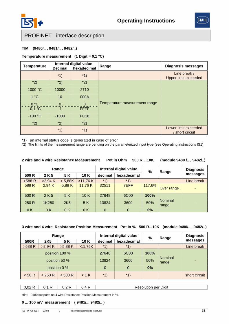
TIM (9480/.. , 9481/.. , 9482/..)
Temperature measurement (1 Digit = 0,1 °C)
TemperatureInternal digital value
Range Diagnosis messagesDecimal hexadecimal
*1) *1)Line break /
Upper limit exceeded*2) *2) *2)
Temperature measurement range
. . .
1000 °C 10000 2710. . .
1 °C 10 000A. . .
0 °C 0 0-0,1 °C -1 FFFF
. . .
-100 °C -1000 FC18. . .
*2) *2) *2)
*1) *1)Lower limit exceeded
/ short circuit
*1) an internal status code is generated in case of error*2) The limits of the measurement range are pending on the parameterized input type (see Operating instructions IS1)
2 wire and 4 wire Resistance Measurement Pot in Ohm 500 R ...10K (module 9480 /.. , 9482/..)
Range Internal digital value% Range
Diagnosismessages500 R 2 K 5 5 K 10 K decimal hexadecimal
>588 R >2,94 K > 5,88K >11,76 K *1) *1) Line break588 R 2,94 K 5,88 K 11,76 K 32511 7EFF 117,6%
Over range -. . .
500 R 2 K 5 5 K 10 K 27648 6C00 100%
Nominalrange
-. . .
250 R 1K250 2K5 5 K 13824 3600 50%. . .
0 K 0 K 0 K 0 K 0 0 0%
3 wire and 4 wire Resistance Position Measurement Pot in % 500 R...10K (module 9480/.. , 9482/..)
Range Internal digital value% Range
Diagnosismessages500R 2K5 5 K 10 K decimal hexadecimal
>588 R >2,94 K >5,88 K >11,76K *1) *1) Line break
position 100 % 27648 6C00 100%Nominalrange
-. . .
position 50 % 13824 3600 50%. . .
position 0 % 0 0 0%
< 50 R < 250 R < 500 R < 1 K *1) *1) short circuit
0,02 R 0,1 R 0,2 R 0,4 R Resolution per Digit
Hint: 9480 supports no 4 wire Resistance Position Measurement in %.
0 ... 100 mV measurement ( 9481/.., 9482/.. )

Operating Instructions
32 IS1 PROFINET V2.04 E - Technical alterations reserved -
PROFINET interface description
Range0 ... 100 mV
Internal digital value% Range Diagnosis messages
decimal hexadecimal
>117,6 mV *1) *1) Upper limit exceeded117,6 mV 32511 7EFF 117,6 %
Over range -
100 mV 27648 6C00 100 %
Nominal range -. . .
50 mV 13824 3600 50 %. . .
0 mV 0 0 0 %-0,0036 mV -1 FFFF
Under range
(9481/..)(9482/..)
--10 mV-117,6 mV
-2765-32511
F5338101
-10 %-117,6%
< *1) *1) Lower limit exceeded
*1) an internal status code is generated in case of error
Short circuit alarm cannot be detected at Resistance and Voltage measurement !
For 2 wire calibration of module TIM R 9480/.. and TIM 9482/.. the user interface (LCD display with buttons)of the CPM has to be used.

Operating Instructions
IS1 PROFINET V2.04 E - Technical alterations reserved 33
PROFINET interface description
AOM 0 – 20 mA (9465/... , 9466/..., 9468/..)
Measuringrange
0 – 20 mA
Internal digital value% Range
Decimal Hexadecimal
*1) >30137 >75B921,8 mA 30137 75B9 109%
Over range. . .
20 mA 27648 6C00 100%
Nominal range. . .
10 mA 13824 3600 50%. . .
0 mA 0 0 0%0 mA < 0 < 0
AOM 4 – 20 mA
Measuringrange
4 – 20 mA
Internal digital value% Range
Decimal Hexadecimal
*1) >30759 >782721,8 mA 30759 7827 111,25%
Over range. . .
20 mA 27648 6C00 100%
Nominal range. . .
12 mA 13824 3600 50%. . .
4 mA 0 0 0%3,999 mA -1 FFFF
Under range0 mA -6912 E500 -25%0 mA < -6912 < E500
*1) : The AOM attempts to increase the current further according to the control value. However, depend-ing on the burden effective resistance, the maximum output voltage of the AOM may be reachedwhereby the current can no longer be increased.
Safety position after Power On:After Power On of the CPM the internal data area of the outputs is initialized with the value -32768 (0x8000)as signal for the safety position.The outputs remain in the save position as long as the allocated register is overwritten with a valid outputvalue ( <> -32768 (0x8000)).

Operating Instructions
34 IS1 PROFINET V2.04 E - Technical alterations reserved -
PROFINET interface description
Data word structure cyclic analog data AOM 9465/…, AOMH 9466/…
Data ByteOperation mode
SubslotVar.Type
Signals8AO 8AO+8HV
Input
1 – 5 AOR 0 AOR 0
1
Float 32+ Status
DSARIO1
Readback with StatusAO 0 – AO 7
6 – 10 AOR 1 AOR 1
11 – 15 AOR 2 AOR 2
16 – 20 AOR 3 AOR 3
21 – 25 AOR 4 AOR 4
26 – 30 AOR 5 AOR 5
31 – 35 AOR 6 AOR 6
36 – 40 AOR 7 AOR 7
1 – 4
-
HV-P1
2 Float 32HART Variables transmitted
on positions P1 - P8
5 – 8 HV-P2
9 – 12 HV-P3
13 – 16 HV-P4
17 – 20 HV-P5
21 – 24 HV-P6
25 – 28 HV-P7
29 – 32 HV-P8
Output
1 – 5 AO 0 AO 0
1
Float 32+ Status
DSARIO1
Analog output signalsAO 0 – AO 7
Analog format with statusaccording PI specification
6 – 10 AO 1 AO 1
11 – 15 AO 2 AO 2
16 – 20 AO 3 AO 3
21 – 25 AO 4 AO 4
26 – 30 AO 5 AO 5
31 – 35 AO 6 AO 6
36 – 40 AO 7 AO 7
Operating Instructions
IS1 PROFINET V2.04 E - Technical alterations reserved 35
PROFINET interface description
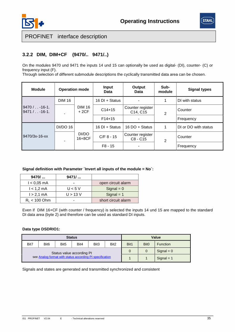
3.2.2 DIM, DIM+CF (9470/.. 9471/..)
On the modules 9470 und 9471 the inputs 14 und 15 can optionally be used as digital- (DI), counter- (C) orfrequency input (F).Through selection of different submodule descriptions the cyclically transmitted data area can be chosen.
Module Operation modeInputData
OutputData
Sub-module
Signal types
9470 / . . -16-1.9471 / . . -16-1.
DIM 16
DIM 16+ 2CF
16 DI + Status - 1 DI with status
-C14+15
Counter registerC14, C15 2
Counter
F14+15 - Frequency
9470/3x-16-xx
DI/DO 16
DI/DO16+8CF
16 DI + Status 16 DO + Status 1 DI or DO with status
-C/F 8 - 15
Counter registerC8 - C15 2
Counter
F8 - 15 - Frequency
Signal definition with Parameter ´Invert all inputs of the module = No´:
9470/ ... 9471/ ...
I < 0,05 mA - open circuit alarm
I < 1,2 mA U < 5 V Signal = 0
I > 2,1 mA U > 13 V Signal = 1
RL < 100 Ohm - short circuit alarm
Even if DIM 16+CF (with counter / frequency) is selected the inputs 14 und 15 are mapped to the standardDI data area (byte 2) and therefore can be used as standard DI inputs.
Data type DSDRIO1:
Status Value
Bit7 Bit6 Bit5 Bit4 Bit3 Bit2 Bit1 Bit0 Function
Status value according PIsee Analog format with status according PI specification
0 0 Signal = 0
1 1 Signal = 1
Signals and states are generated and transmitted synchronized and consistent

Operating Instructions
36 IS1 PROFINET V2.04 E - Technical alterations reserved -
PROFINET interface description
Data
Data Byte
all DIM(9470/3x in compatible
mode)
DIOM 9470/3x(IS1+) Sub-
moduleType Application
DIMDIM
+2CFDI/DO
DI/DO+8CF
Input
1 DI 0 + Status
1
UINT8RIO Data
Type 6
DSDRIO1
DI Signals with Status2 DI 1 + Status
. . . . . . .
16 DI 15 + Status
1-3 C 14 C 8
2
UINT16+Status
DSARIO2
Counter 16Bit
Up/DownCounter 16
Bit
Not updated(= 0) if Opera-tion mode =
32 Bit
4-6 C 15 C 9
7-9 C 10
. . . . . . .
23+24 C 15
25-29
- -
C 8, 9
UINT32+Status
DSARIO4
Up/DownCounter 32
Bit
Not updated(= 0) if Opera-tion mode =
16 Bit
30-34 C 10, 11
35-39 C 12, 13
40-44 C 14, 15
45-49F 14 F 8
Float 32+Status
DSARIO1
Counter and Frequencymeasurementwith scaling.
counter scaling:16 Bit: 0% = 0, 100% = 2
16-1
32 Bit: 0% = 0, 100% = 232
-1
*1)
(7-11)
50-54F 15 F 9
(12-16)
. . .
-
. . . .
75-79 F 14
80-84 F 15
Output
1
- -
DO 0 + Status
1
UINT8RIO Data
Type 6
DSDRIO1
DO Signals with Status2 DO 1 + Status
. . . . . . .
16 DO 15 + Status
1
-
C14,15Start, Stop
Reset -
ResetC8-15
2 BitStr. 8 Counter control register
2 ReservedStart/Stop
C8-15
*1) Using an input pair in operation mode Up/Down counter or frequency with direction, then the first Float 32 variable ofthe pair represents the scaled value. The second Float variable of the pair is delievering the error code ´Not a number´.The scaling parameters of the second Float variable have not function in this case.
Counter control register DIM+2CF: Counter control register DIOM+8 CF
Byte Bit Function Allocation
1
0 Reset Counter C14 0 = Run,1 = Reset ( Counter = 0)1 Reset Counter C15
2 Start/Stop C14 0 = Counter Run,1 = Counter Stop3 Start/Stop C15
4 - 7 Reserved -
2 0 - 7 Reserved -
Byte Bit Function
1
0 Reset Counter C8
. . . . . .
7 Reset Counter C15
2
0 Start/Stop C8
. . . . . .
7 Start/Stop C15
Operating Instructions
IS1 PROFINET V2.04 E - Technical alterations reserved 37
PROFINET interface description
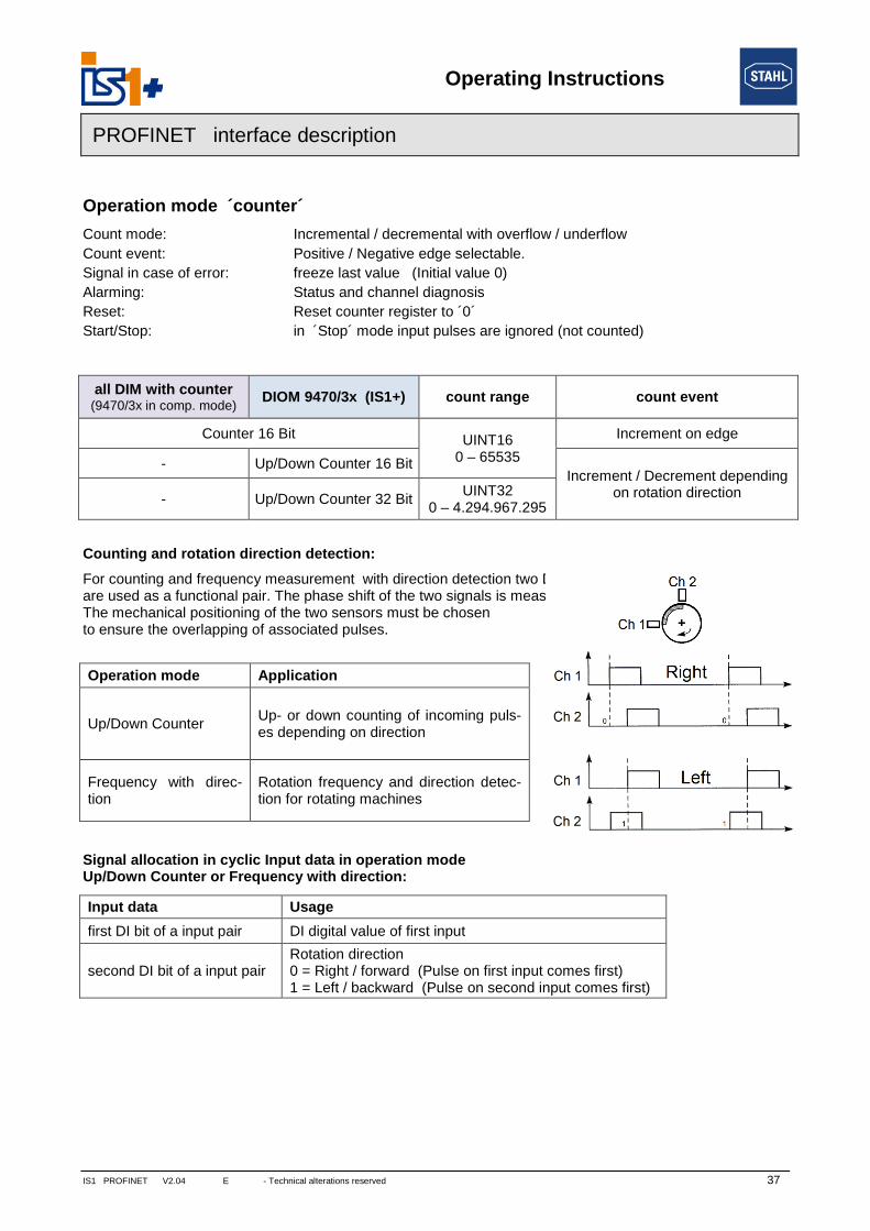
Operation mode ´counter´
Count mode: Incremental / decremental with overflow / underflow
Count event: Positive / Negative edge selectable.
Signal in case of error: freeze last value (Initial value 0)
Alarming: Status and channel diagnosis
Reset: Reset counter register to ´0´
Start/Stop: in ´Stop´ mode input pulses are ignored (not counted)
all DIM with counter(9470/3x in comp. mode)
DIOM 9470/3x (IS1+) count range count event
Counter 16 Bit UINT160 – 65535
Increment on edge
- Up/Down Counter 16 BitIncrement / Decrement depending
on rotation direction- Up/Down Counter 32 BitUINT32
0 – 4.294.967.295
Counting and rotation direction detection:
For counting and frequency measurement with direction detection two DI Inputsare used as a functional pair. The phase shift of the two signals is measured.The mechanical positioning of the two sensors must be chosento ensure the overlapping of associated pulses.
Signal allocation in cyclic Input data in operation modeUp/Down Counter or Frequency with direction:
Input data Usage
first DI bit of a input pair DI digital value of first input
second DI bit of a input pairRotation direction0 = Right / forward (Pulse on first input comes first)1 = Left / backward (Pulse on second input comes first)
Operation mode Application
Up/Down CounterUp- or down counting of incoming puls-es depending on direction
Frequency with direc-tion
Rotation frequency and direction detec-tion for rotating machines
Operating Instructions
38 IS1 PROFINET V2.04 E - Technical alterations reserved -
PROFINET interface description
Signal and status in operation mode ´counter´:
Counters are set to 0 during IOM startup.The status bit is initialized with 0x24 = signal disturbed (bad).With the Reset bit in the control register the counter register is set to ´0´ and the status bit is setto 0x80 = signal OK.In case of errors (short circuit, open circuit, bus failure ...) the status bit is set to bad and will be held at baduntil the next Reset. Therefore disturbances during the count procedure are recognizable via the status bit.In case of lost Data Exchange with the AS and recover within the parameterized output holt time or in case ofCPU redundancy switch over the count procedure will not be disturbed.Using an input pair in operation mode Up/Down counter or frequency with direction the status bits of bothchannels are set to bad in case of a signal error of one of the two channels.
For summation of 16 Bit counters in the AS the count difference of two consecutive read cycles must beadded from the AS. Counter overflow / underflow must be detected and considered. Maximum one overflow/ underflow within one AS cycle shall occur.
32 Bit counter with direction inputFor counting without direction detection only the first input of a 32 Bit Up/Down Counter channel pair shall beused. The direction bit must not be used by PLC in this case. Error detection of the second not used inputchannel shall be set to Off. Pulses on the first input will increment the counter if the second input is open.Pulses on the first input will decrement the counter if the second input is shorted.
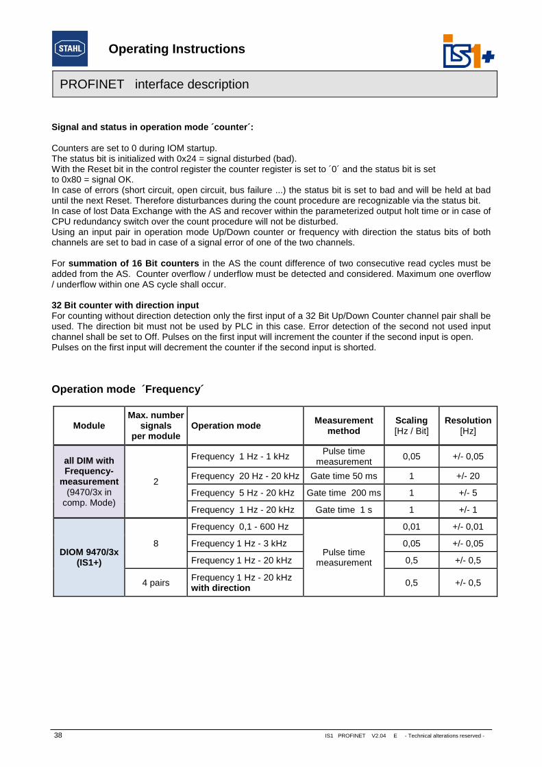
Operation mode ´Frequency´
ModuleMax. number
signalsper module
Operation modeMeasurement
methodScaling[Hz / Bit]
Resolution[Hz]
all DIM withFrequency-
measurement(9470/3x in
comp. Mode)
2
Frequency 1 Hz - 1 kHzPulse time
measurement0,05 +/- 0,05
Frequency 20 Hz - 20 kHz Gate time 50 ms 1 +/- 20
Frequency 5 Hz - 20 kHz Gate time 200 ms 1 +/- 5
Frequency 1 Hz - 20 kHz Gate time 1 s 1 +/- 1
DIOM 9470/3x(IS1+)
8
Frequency 0,1 - 600 Hz
Pulse timemeasurement
0,01 +/- 0,01
Frequency 1 Hz - 3 kHz 0,05 +/- 0,05
Frequency 1 Hz - 20 kHz 0,5 +/- 0,5
4 pairsFrequency 1 Hz - 20 kHzwith direction
0,5 +/- 0,5

Operating Instructions
IS1 PROFINET V2.04 E - Technical alterations reserved 39
PROFINET interface description
Signal scaling:
all DIM with Frequency measurement (9470/3x in compatible mode):
Measuring range Units% *1) Range
1 Hz – 1 kHz x – 20 kHz decimal hex
1,3 kHz - 26000 6590 130 %Over range1,1 kHz 22 kHz 22000 55F0 110 %
1 kHz 20 kHz 20000 4E20 100 %
Nominal range. . . .
500 Hz 10 kHz 10000 2710 50 %. . . .
0 Hz 0 kHz 0 0 0 %
DIOM 9470/3x (IS1+)
Measuring range Units% *1) Range
0,1 Hz – 600 Hz 1 Hz – 3 kHz 1 Hz - 20 kHz Dec. Hex> 655,34 Hz > 3,276 kHz - 65535 0xFFFF Overflow655,34 Hz 3,276 kHz - 65534 0xFFFE 164 % Over range
600 Hz440 Hz
3 kHz2,2 kHz
- 60000 0xEA60 150 %22 kHz 44000 0xABE0 110 %
400 Hz 2 kHz 20 kHz 40000 0x9C40 100 %
Nominal range. . . . .
500 Hz 1 kHz 10 kHz 20000 0x4E20 50 %. . . . .
0 Hz 0 kHz 0 kHz 0 0x0000 0 %
*1) Scaling of frequency measurements in IS1 DTM.
all DIM with Frequency (9470/3x in comp. mode) Phys. 0 – 100% correlate digital 0 – 20000DIOM 9470/3x (IS1+) Phys. 0 – 100% correlate digital 0 – 40000
Signal in case of error: freeze (Initial value 0)Diagnosis: status und channel diagnosis
Behavior in case of too high input frequencies:If the input frequency is higher than 22 kHz input pulses can be lost. In this case the measured value issmaller as the existing frequency at the input. No alarm is generated.
Signal Filter:The measured frequency signal can be filtered by the DIOM 9470/3x to reduce jitter.Additionally a pulse extension function is executed for the DI signals.
Parameter SelectionPulse extension
for DI signalsFilter / smoothing
for frequency measurement
Pulse extension /Frequency Filter
0 s / off 0 s off0,6 s / small 0,6 s small
1,2 s / medium 1,2 s medium2,4 s / large 2,4 s large

Operating Instructions
40
PROFINET interface description
Pulse extension:
This function can be used to increase the length of short pulses. With this e.g. a short activity of a manualsensor (term approx. 10 .. 50 ms) can be extended to a time selectable by parameterization (T = 0,6 sec.,1.2 sec., 2.4 sec.).Short pulses can be recognized surely from the AS also with slower cycle times of the application software
Pulse extension with not inverted operation:(Parameter ´Invert all inputs of the module´ = No)
Pulses which are longer than thShort pulses during time T are
Pulse extension with inverte(Parameter ´Invert all inputs of the mod
Signal LEDs:DIOM with signal LEDs display
Input signal
Signal to AS
Input signal
Signal to AS
sec.
Input signal
Signal to AS
e parameterized time T, are not extended.suppressed.
d operation:ule´ = Yes)
T
T
IS1
the extended ´Signal to AS.
T
T = 0,6 sec., 1,2 sec., 2,4
PROFINET V2.04 E - Technical alterations reserved -

Operating Instructions
IS1 PROFINET V2.04 E - Technical alterations reserved 41
PROFINET interface description
3.2.3 DOM (9475/.., 9477/.., 9478/..)
Signal allocation
Readback: The written output value can be read via Bit 0 of the associated status byte.
Datatype DSDRIO1: (data type numerical identifier 0x105)
Status Value
Bit7 Bit6 Bit5 Bit4 Bit3 Bit2 Bit1 Bit0 DOM DOMR DOMV
Status value acc. PI
see Analog format with status accord-ing PI specification
x 0 Falseoutput high impedance( actuator = Off )
relay contact= open
Valve closed
x 1 Trueoutput is powered acc.type specification( actuator = On )
relay contact= closed
Valve open
X: Bit = 0 ( reserved)
Daten ByteDOM 8 DOM 6 DOM 4 Sub-
moduleType
9477/12-06-12
Input
1 Status_S0 Status_S0 Status_S0
1
UINT8RIO Data
Type 6
DSDRIO1
Status withreadback
2 Status_S1 Status_S1 Status_S1
3 Status_S2 Status_S2 Status_S2
4 Status_S3 Status_S3 Status_S3
5 Status_S4 Status_S4 -
6 Status_S5 Status_S5 -
7 Status_S6 - -
8 Status_S7 - -
Output
1 DO 0 DO 0 DO 0
1
UINT8RIO Data
Type 6
DSDRIO1
2 DO 1 DO 1 DO 1
3 DO 2 DO 2 DO 2
4 DO 3 DO 3 DO 3
5 DO 4 DO 4 -
6 DO 5 DO 5 -
7 DO 6 - -
8 DO 7 - -

Operating Instructions
42 IS1 PROFINET V2.04 E - Technical alterations reserved -
PROFINET interface description
3.3 HART variables
In addition to the analogue process value, HART field devices offer the option of digitally reading up to fourprocess variables (HART variables HV) from the transmitter.IS1 offers the option of mapping such HART variables to the cyclic input data area of PROFINET.Optionally eight HART variables of an IS1 HART module (AIMH, AUMH, AOMH) can be transmitted in addi-tion to the cyclic data.This can be selected optionally when configuring a field station.
3.3.1 Data format
HART variables are transmitted as IEEE floating-point numbers (4 bytes).If a HART variable cannot be read (e.g. HART device undergoing startup, not connected, defective or HARTvariable not found, ... ), value 7F A0 00 00 (Not a Number) is transmitted. This may be evaluated in the ASfor generation of a signal status of the HART variables. Detailed status and diagnostic information on theHART field devices can be evaluated via HART Management Systems.
3.3.2 Selection of HART Variables
Up to 8 HART field devices can be connected to one HART module of IS1. Since each HART field devicemay have up to 4 variables, this mean that a maximum of 32 HART variables are possible per module.The assignment of 4 or 8 out of these 32 variables to the positions P1 to P8 in the cyclic transmission areacan be selected by parameter assignment:
Parameter nameValuerange
Function
Input No. HART device for pos. 1
0 ... 7,Not used
Selection of the channel No. (input / output No.) of the HART moduleto which the HART field device is connected which is to be transmittedat pos. 1.If ´Not Used´ is selected, value ´Not a Number´ (7F A0 00 00) istransmitted.
Input No. HART device for pos. 2 Selection for pos. 2
. . . . . . . . . .
Input No. HART device for pos. 4 (8) Selection for pos. 4 (8)
HART variable for pos. 1
1, 2, 3, 4
Selection of the variables of the HART field device which is to betransmitted at pos. 1.
HART variable for pos. 2 Selection for pos. 2
. . . . . . . . . .
HART variable for pos. 4 (8) Selection for pos. 4 (8)
Operating Instructions
IS1 PROFINET V2.04
PROFINET interface description
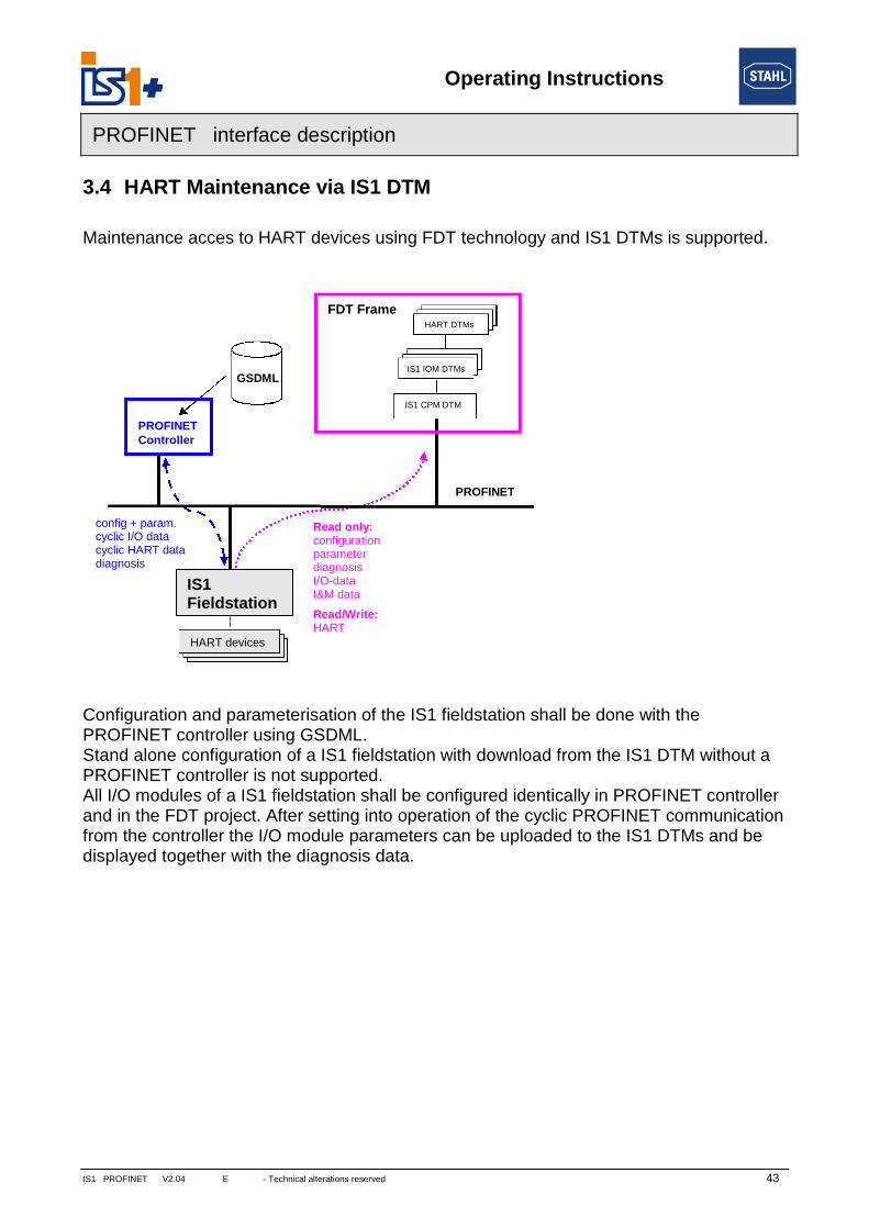
3.4 HART Maintenance via IS1 DTM
Maintenance acces to HART devices using FDT technology and IS1 DTMs is supported.
ConfigurationPROFINET coStand alone cPROFINET coAll I/O moduleand in the FDTfrom the contrdisplayed toge
Fieldstation
PROFINET
diagnosis
Read only:configurationparameterdiagnosisI/O-dataI&M data
Read/Write:HART
PROFINETController
GSDML
sFDT Frame
IS1 CPM DTM
HART DTMs
sIS1 IOM DTMs
HART devices
IS1
config + param.cyclic I/O datacyclic HART data
E - Technical alterations reserved
and parameterisation of the ISntroller using GSDML.
onfiguration of a IS1 fieldstationtroller is not supported.s of a IS1 fieldstation shall be
project. After setting into opeoller the I/O module parametether with the diagnosis data.
HART deviceHART device
HART DT
MHART DTMHART DT
MHART DTM43
1 fieldstation shall be done with the
n with download from the IS1 DTM without a
configured identically in PROFINET controllerration of the cyclic PROFINET communicationrs can be uploaded to the IS1 DTMs and be

Operating Instructions
44 IS1 PROFINET V2.04 E - Technical alterations reserved -
PROFINET interface description
3.5 Alarm- and diagnosis data
Module Alarms
Alarm-Messages Description Measure / RemedyIOM Status
(NE107)
CPU_ALARM_WRONG Wrong CPU Insert right CPU type
Failure
IOM_ALARM_CONFIGIS1 configuration errorfrom IO Controller!
Plug configured module type orchange configuration of control-lerIOM_ALARM_WRONG Wrong module
IOM_ALARM_HW_ERR IOM hardware failure Exchange module
IOM_ALARM_NOT No modulePlug correct module type orexchange module.
IOM_ALARM_PLUG Module plug event- - -
IOM_ALARM_PULL Module pull event
IOM_ALARM_BUS_PRIM primary rail disturbed Check IOM, Rail communica-tion and CPM
MaintenanceRequiredIOM_ALARM_BUS_RED redundant rail disturbed
IOM_ALARM_OUT_DISIOM hardware disableoutputs.
Outputs of DOM 9475 areswitched off by hardware disa-ble input. Output data from ASis rejected. Check and clearreason for hardware disable.
Failure
IOM_ALARM_OVER_TEMP Overtemperature
Ambient temperature aroundthe IOM is too high. Reduceambient temperature or in-crease ventilation, shadowing…
Out of spec
IOM_ALARM_SLOT_ADR_FAIL
Slot address error
The module has detected aincorrect change of the slotaddress during operation. ->exchange IOM and send it backto STAHL service.
MaintenanceRequired
IOM_ALARM_MAINT_REQModule maintenancerequest
Exchange of module recom-mended due to operating condi-tions.
Module9475/3x-04-72 DOM4only
Maximum total output current ofmodule exceeded .Channel 3 is switched off.Reduce total loop current.
Out of spec

Operating Instructions
IS1 PROFINET V2.04 E - Technical alterations reserved 45
PROFINET interface description
Channel Alarms
CHAN_ALARM_SC Short circuit
Check connection between IOMand sensor/actuator and removeshort.
Check sensor / actuator andreplace if required
Failure
CHAN_ALARM_LB Open circuit
Check and reestablish connec-tion between IOM and sen-sor/actuator.
Check sensor / actuator andreplace if required
Channel-Diagnoses
Message / Function Measure / RemedySignal Status
(NE107)
CHAN_DIAG_OVERTEMPAmbient temperature of SAIMH is too high.Reduce ambient temperature or increase ventilation, shad-owing …
Failure
CHAN_DIAG_UPP_LIM_EXCEED Measurement range limit of IOM (TIM) is exceeded.Use input signal inside allowed measurement range orchoose different range if possible.
FailureCHAN_DIAG_LOW_LIM_EXCEED
2_WIRE_CALIBRATION_FAILEDRepeat 2 wire calibration. Look for a good short at the wireend during calibration.
Failure
Signal status see Analog format with status according PI specification
Module and channel errors are reported via submodule 1 only.
Operating Instructions
46 IS1 PROFINET V2.04 E - Technical alterations reserved -
PROFINET interface description
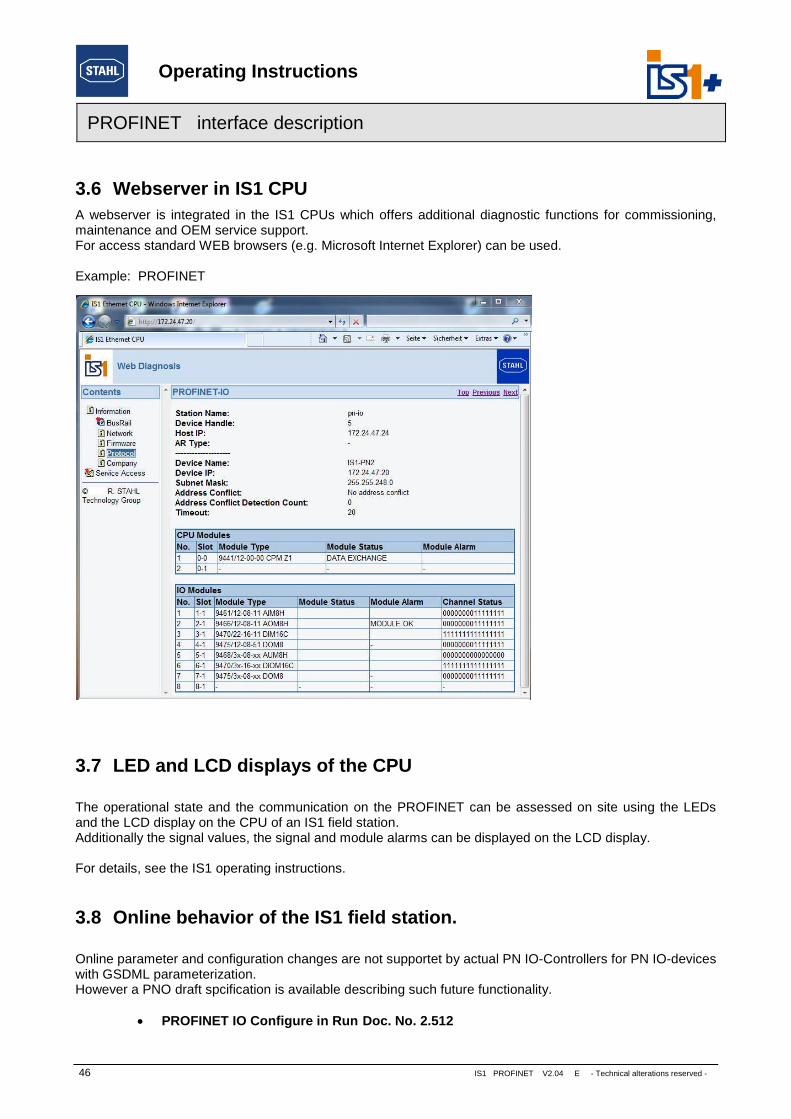
3.6 Webserver in IS1 CPU
A webserver is integrated in the IS1 CPUs which offers additional diagnostic functions for commissioning,maintenance and OEM service support.For access standard WEB browsers (e.g. Microsoft Internet Explorer) can be used.
Example: PROFINET
3.7 LED and LCD displays of the CPU
The operational state and the communication on the PROFINET can be assessed on site using the LEDsand the LCD display on the CPU of an IS1 field station.Additionally the signal values, the signal and module alarms can be displayed on the LCD display.
For details, see the IS1 operating instructions.
3.8 Online behavior of the IS1 field station.
Online parameter and configuration changes are not supportet by actual PN IO-Controllers for PN IO-deviceswith GSDML parameterization.However a PNO draft spcification is available describing such future functionality.
PROFINET IO Configure in Run Doc. No. 2.512
Operating Instructions
IS1 PROFI
PROFINET interface description
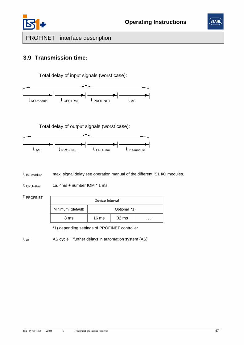
3.9 Transmission time:
t I/O-mod
t CPU+R
t PROFIN
t AS
t I/O-
t A
module t CPU+Rail t PROFINET t AS
Total delay of input signals (worst case):
NET V2.04 E - Technical alterations reserved 47
ule max. signal delay see operation manual of the different IS1 I/O modules.
ail ca. 4ms + number IOM * 1 ms
ET
*1) depending settings of PROFINET controller
AS cycle + further delays in automation system (AS)
Device Interval
Minimum (default) Optional *1)
8 ms 16 ms 32 ms . . .
S t PROFINET t CPU+Rail t I/O-module
Total delay of output signals (worst case):

Operating Instructions
48 IS1 PROFINET V2.04 E - Technical alterations reserved -
PROFINET interface description
4 List of abbreviations:
AS Automation SystemAIM Analogue Input ModuleAIMH Analogue Input Module + HARTAUMH Analog Universal Module AI/AO with HARTSAIMH Safety Analogue Input Module + HART (PROFIsafe)AOM Analogue Output ModuleAOMH Analogue Output Module +HARTCPM CPU + PM = CPM
Central unit consisting of communication processor with power packDIM Digital Input ModuleDIOM Digital Input Output ModuleDOM Digital Output ModuleDOMR Digital Output Module RelaysDOMV Digital Output Module ValvesHW HardwareIOP I/O Processor of the central unitIOM General description of I/O ModulePM Power Module (power pack)SW SoftwareSIL Safety Integrity LevelTIM Temperature Input Module
Operating Instructions
IS1 PROFINET V2.04 E - Technical alterations reserved 49
PROFINET interface description
5 Release notes:
Version
Interface descriptionPROFINET
Extensions / Changes
V 2.00 First official release
V 2.02 Signal Type of MIN_VALUE and MAX_VALUE changed to Float
V 2.03 HART communication via IS1 DTM added
V 2.04 new IS1+ IOM 9482 TIM added
6 Further reading
PROFINET Design Guideline PNO Doc. 8.062
PROFINET Installation Guideline for Cabling and Assembly PNO Doc. 8.072
PROFINET Installation Guideline for Commissioning PNO Doc. 8.082
7 Support address
R. Stahl Schaltgeraete GmbH
Center of Competence Instrumentation Systems
eMail: [email protected]
Support information: http://www.stahl.de
Service hotline IS1: +49 (7942) 943-4123
Fax : +49 (7942) 943-40 4123