operating instructions - socomec · one of socomec’s catalogue products: the pti. please contact...
TRANSCRIPT

DIRIS A60Operating instructions
F GB D I NL E P

2 DIRIS A60 - Ref.: 536 418 A GB
DANGER AND WARNING _______________________ 3PRELIMINARY OPERATIONS ____________________ 4PRESENTATION ________________________________ 5INSTALLATION _________________________________ 6PROGRAMMING ______________________________ 12OPERATION __________________________________ 43CONNECTION TEST FUNCTION ________________ 48ASSISTANCE _________________________________ 52TECHNICAL CHARACTERISTICS ________________ 53GLOSSARY OF ABBREVIATIONS _______________ 56
Co
nten
ts

3DIRIS A60 - Ref.: 536 418 A GB
This equipment must be mounted only by professio-nals. The manufacturer shall not be held responsible for failure to comply with the instructions in this manual.
Risk of electrocution, burns or explosion• the device must be installed and serviced only by
qualified personnel• prior to any work on or in the device, isolate the
voltage inputs and auxiliary power supplies and short-circuit the secondary winding of all current transfromers (PTI SOCOMEC)
• always use an appropriate voltage detection device to confirm the absence of voltage
• put all mechanisms, door and covers back in place before energising the device
• always supply the device with the correct rated vol-tage
Failure to take these precautions could cause serious injuries.
Risk of damaging deviceChek the following :
• the voltage of the auxiliary power• the frequency of the distribution system (50 or
60 Hz)• the maximum voltage across the voltage-input ter-
minals, (V1, V2, V3 and VN) 500 V AC phase-to-phase or 289 V AC phase-to-neutral
• a maximum current of 6 A on the current-input ter-minals (I1, I2 and I3)
DANGER AND WARNING

4 DIRIS A60 - Ref.: 536 418 A GB
DANGER AND WARNING
For personnel and product safety please read the contents of these operating instructions carefully before connecting.Check the following points as soon as you receive the package:• the packing is in good condition,• the product has not been damaged during transit,• the product reference number conforms to your
order,• the packaging included a product fitted with deta-
chable terminal strips,• operating instructions.

5DIRIS A60 - Ref.: 536 418 A GB
PRÉSENTATION
1. Key-pad with 6 dual-function keys (display or pro-gramming)
2. Backlit LCD display3. Phase4. Values5. Unit6. Activity indicator on the communication bus7. Energy metering indication8. Hour meter and energy display9. Alarm relay 110. Alarm relay 2

6 DIRIS A60 - Ref.: 536 418 A GB
INSTALLATION
• avoid being close to systems generating elec-tromagnetic disturbances,
• avoid vibrations involving accelerations greater than 1 G for frequencies lesser than 100 Hz.
RECOMMENDATIONS
CUT-OUT DIAGRAM, MOUNTIG
3.62
+0.
03 in
92 +
0,8 m
m0
0
3.62 +0.03 in92 +0,8 mm0
0
Max. 0.31 in
Max. 8 mm
ni 87.3m
m 69
3.82 in97 mm
ni 45.3m
m 09
0.94 in24 mm
ni 02.2m
m 65
ni 51.3m
m 08
ni 28.0m
m 12
3.54 in90 mm

7DIRIS A60 - Ref.: 536 418 A GB
CONNECTION
Each CT’s secondary winding must be short-circuited when disconnecting the DIRIS. This can be done automatically using one of Socomec’s catalogue products: the PTI. Please contact us for further informa-tion.
DIRIS A60
Å Aux.: IEC / CE 110 … 400 V AC 120 … 350 V DC 12 … 48 V DCÇ Fus.: 0.5 A gG / BS 88 2A gG / 0.5 A class CC
DIRIS A60
INSTALLATION
S2 S1 S2 S1 S2S1I2 I3I1
V1 V2 V3 VN1
2
8171+ -
Input Synchro10...30 V DC
0.24 in / 6 mm
Flat 3,5
0,5 mm² - 2,5 mm²
0.27 in / 7 mm
Flat 5,5Pozidriv 1
0,5 mm² - 6 mm²
7lb-in / 0.8Nm
3.5lb-in / 0.4Nm

8 DIRIS A60 - Ref.: 536 418 A GB
INSTALLATION
MODULES OPTION
DIRIS A60 can be fitted with optional modules: - JBUS/MODBUS communication;
ref: 4825 0092: RS485 JBUS/MODBUS serial port in RTU
mode with a speed from 2400 to 38400 baud. (Operating instructions ref: 536 103).
- PROFIBUS-DP Communication; ref: 4825 0205:
RS485 PROFIBUS-DP serial port with a speed from 9,600 baud to 12 Mbaud.
(Operating instructions ref: 535 749). - Pulse outputs; ref: 4825 0090: 2 pulse outputs connected to the metering of
energy in kWh, kvarh and KVAh. (Operating instructions ref: 536 045). - Analogue outputs; ref: 4825 0093: 2 analogue outputs 4/20 mA or 0/20 mA confi-
gurable for measures performed by the DIRIS A60. 2 modules can be installed, a maximum of 4 outputs.
(Operating instructions ref: 536 048). - Inputs/Outputs; ref: 4825 0094: 2 outputs allocated for alarms, for voltage, cur-
rent, power, power factor and THD, or remote control.
2 inputs for the metering of pulses or control-ling position.
(Operating instructions ref: 536 047). - Ethernet; réf : 4825 0203 : Link with RJ45 connector. P ro toco l MODBUS/TCP o r JBUS/
MODBUS RTU with TCP. WEB-ser-ver for configuration of the product, dis-play of the main quantities and diagnosis. (Operating instructions ref.: 535 748).
- Ethernet/gateway RS485; ref: 4825 0204: Link with RJ 45 connector. Master gateway function MODBUS with 3
points link RS485. Protocol MODBUS/TCP or JBUS/MODBUS
RTU with TCP. WEB-server for the configura-tion of the product, display of the main quan-tities and diagnosis.
(Operating instructions ref.: 535 748). - Temperature; ref: 4825 0206. PT100 Technology: 4 temperature indicators : - 1 internal - 3 external (PT100 input) (Operating instructions ref.: 535 750). - Operating earth; ref.: 48250087 (Operating instructions ref.: 536 423).
DIR
IS 3
43 A

9DIRIS A60 - Ref.: 536 418 A GB
DIR
IS 2
72 E
UNBALANCED THREE-PHASE NETWORK (4NBL)
UNBALANCED THREE-PHASE NETWORK (3NBL)
DIRIS A60
INSTALLATION
DIR
IS 2
78 D
DIR
IS 2
80 D
DIR
IS 2
76 C
Å Aux.: IEC / CE 110 … 400 V AC 120 … 350 V DC 12 … 48 V DCÇ Fus.: 0.5 A gG / BS 88 2A gG / 0.5 A class CC
P1
S1
P1
S1
L1 (R)
L2 (S)
L3 (T)P1
S1
S2 S1 S2 S1 S2S1I2 I3I1
V1 V2 V3 VN AUX
2
1
2
L1 (R)
L2 (S)
L3 (T)
S2 S1 S2 S1 S2S1I2 I3I1
V1 V2 V3 VN AUX
P1
S1
P1
S1
2
2
1
L1 (R)
L2 (S)
L3 (T)
S2 S1 S2 S1 S2S1I2 I3I1
V1 V2 V3 VN AUX
P1
S1
P1
S1
2
1
2
Å Aux.: IEC / CE 110 … 400 V AC 120 … 350 V DC 12 … 48 V DCÇ Fus.: 0.5 A gG / BS 88 2A gG / 0.5 A class CC

10 DIRIS A60 - Ref.: 536 418 A GB
DIRIS A60
INSTALLATION
BALANCED THREE-PHASE NETWORK (3BL/4BL)
The solution using one CT, with the 3rd phase current calculated via vectoral summation, results in an 0.5% reduction in phase accuracy.
P1
S1
L1 (R)
L2 (S)
L3 (T)
S2 S1 S2 S1 S2S1I2 I3I1
V1 V2 V3 VN AUX
2
1
2
DIR
IS 2
82 D
1
2
L1 (R)
L2 (S)
L3 (T)
S2 S1 S2 S1 S2S1I2 I3I1
N
P1
S1
V1 V2 V3 VN AUX
2
DIR
IS 6
79 B
Å Aux.: IEC / CE 110 … 400 V AC 120 … 350 V DC 12 … 48 V DCÇ Fus.: 0.5 A gG / BS 88 2A gG / 0.5 A class CC

11DIRIS A60 - Ref.: 536 418 A GB
DIRIS A60
INSTALLATION
TWO-PHASE NETWORK (2BL)
SINGLE-PHASE NETWORK (1BL)
DIR
IS 2
84 D
N
P1
S1
L1 (R)
S2 S1 S2 S1 S2S1I2 I3I1
V1 V2 V3 VN AUX
2
1
2
Å Aux.: IEC / CE 110 … 400 V AC 120 … 350 V DC 12 … 48 V DCÇ Fus.: 0.5 A gG / BS 88 2A gG / 0.5 A class CC
Å Aux.: IEC / CE 110 … 400 V AC 120 … 350 V DC 12 … 48 V DCÇ Fus.: 0.5 A gG / BS 88 2A gG / 0.5 A class CC
A A A
a a a
L1 (R)
L2 (S)
L3 (T)
V1 V2 V3
1
2
DIR
IS 6
80 B
VOLTAGE TRANSFORMER
P1
S1
L1 (R)
L2 (S)
S2 S1 S2 S1 S2S1I2 I3I1
V1 V2 V3 VN AUX
2
1
2
DIR
IS 2
85 D
Å Aux.: IEC / CE 110 … 400 V AC 120 … 350 V DC 12 … 48 V DCÇ Fus.: 0.5 A gG / BS 88 2A gG / 0.5 A class CC

12 DIRIS A60 - Ref.: 536 418 A GB
DIRIS A60
PROGRAMMING
ACCES TO PROGRAMMING MODE (COdE 100)
x 1
x 1
x 1confirm
x 13 sec

13DIRIS A60 - Ref.: 536 418 A GB
DIRIS A60
PROGRAMMING
NETWORK (Example : NET = 3NBL)
x 1
x 1(1BL)x 2 (2BL)x 3 (3BL)x 4 (3NBL)x 5 (4BL)x 6 (4 NBL)
x 1confirm

14 DIRIS A60 - Ref.: 536 418 A GB
DIRIS A60
PROGRAMMING
x 1
x 1
x 1
x 1
x 1confirm
NOMINAL VOLTAGE OF THE NETWORK (phase/phase) (Example: 4NBL: U=390V)
This value is used for calculating the sliding reference voltage (Ureg) for the detection of the voltage dips and interruption, as well as voltage swell.

15DIRIS A60 - Ref.: 536 418 A GB
DIRIS A60
PROGRAMMING
CURRENT TRANSFORMERS (Example : CT = 1500 / 5A). Maxi 10000/5 ou 10000/1
x 2
x 1
x 1confirm

16 DIRIS A60 - Ref.: 536 418 A GB
DIRIS A60
PROGRAMMING
VOLTAGE TRANSFORMER (Example : Vt = YES)
x 1
x 1
x 1confirm

17DIRIS A60 - Ref.: 536 418 A GB
DIRIS A60
PROGRAMMING
VOLTAGE TRANSFORMER PRIMARY (Example : PR = 20 000 V)
x 2
x 2
x 2
x 1
x 1confirm

18 DIRIS A60 - Ref.: 536 418 A GB
DIRIS A60
PROGRAMMING
VOLTAGE TRANSFORMER SECONDARY (Example : SE = 110 V)
x 1
x 1 (110)x 2 (115)x 3 (120)x 4 (173)x 5 (190)x 6 (60)x 7 (100)
x 1confirm

19DIRIS A60 - Ref.: 536 418 A GB
DIRIS A60
PROGRAMMING
INTEGRATION PERIOD OF AVERAGE AND MAXIMUM CURRENTS (Example : tIME 4I = 20 min)
x 1
x 1 (20 min)x 2 (30 min)x 3 (60 min)x 4 (2 sec)x 5 (10 sec)x 6 (5 min)x 7 (8 min)x 8 (10 min)x 9 (15 min)
x 1confirm

20 DIRIS A60 - Ref.: 536 418 A GB
DIRIS A60
PROGRAMMING
INTEGRATION PERIOD OF AVERAGE AND MAXIMUM VOLTAGES (Example : tIME U/V = 20 min)
x 1
x 1 (20 min)x 2 (30 min)x 3 (60 min)x 4 (10 sec)x 5 (5 min)x 6 (8 min)x 7 (10 min)x 8 (15 min)
x 1confirm

21DIRIS A60 - Ref.: 536 418 A GB
DIRIS A60
PROGRAMMING
INTEGRATION PERIOD OF AVERAGE AND MAXIMUM FREQUENCIES (Example : tIME F = 20 min)
x 1
x 1 (20 min)x 2 (30 min)x 3 (60 min)x 4 (10 sec)x 5 (5 min)x 6 (8 min)x 7 (10 min)x 8 (15 min)
x 1confirm

22 DIRIS A60 - Ref.: 536 418 A GB
DIRIS A60
PROGRAMMING
INTEGRATION OF POWER (Example : tIME P/Q/S = 20 min)
x 1
x 1 (20 min)x 2 (30 min)x 3 (60 min)x 4 (10 sec)x 5 (5 min)x 6 (8 min)x 7 (10 min)x 8 (15 min)
x 1confirm

23DIRIS A60 - Ref.: 536 418 A GB
DIRIS A60
PROGRAMMING
RESET OF THE MEMORIZED VALUES (Example : rSET = Ea)
x 1confirm
x 1
x 1
x 1
x 1 (MAX U)x 2 (MAX V)x 3 (MAX F)x 4 (MAX P+)x 5 (MAX P-)x 6 (MAX Q+)x 7 (MAX Q-)x 8 (MAX S)x 9 (HOUR)x 10 (EA+)x 11 (ER+)
x 12 (ES)x 13 (EA-)x 14 (ER-)x 15 (E1)*x 16 (E2)*x 17 (E3)*x 18 (E4)*x 19 (E5)*x 20 (E6)*x 21 (MAX 4I)
* Indication only if I/O 4825 0094 module is present.

24 DIRIS A60 - Ref.: 536 418 A GB
DIRIS A60
MODE OF OPERATION OF BACKLIGHTING (Example : bACLIT = AUX)
PROGRAMMING
x 1
x 1 (AUX)x 2 (I)x 3 (U)
x 1confirm

25DIRIS A60 - Ref.: 536 418 A GB
DIRIS A60
PROGRAMMING
MODE OF OPERATION OF HOUR METER (Example : hour meter (for current) with start-up at 1000A)
x 1
x 1confirm
x 1
x 1
x 1
x 1confirm
x 1 (I)x 2 (U)x 3 (E1)*
x 4 (E2)*x 5 (E3)*x 6 (E4)*
x 7 (E5)*x 8 (E6)*x 9 (AUX)
* Indication only if I/O 4825 0094 module is present.

26 DIRIS A60 - Ref.: 536 418 A GB
DIRIS A60
PROGRAMMING
INTERNAL OR EXTERNAL SYNCHRONIZING PULSE (Example : MEMO TOP = EXT)
x 1confirm
x 1
x 1 (EXT)x 2 (INT)
Remark:This function is used for synchronizing the period of the Power load curves on:INTERNAL PULSE = synchronisation en fonction de l’horloge interne du DIRIS.EXTERNAL PULSE = synchronization as per the pulse received by the syn-chronization input of the module.

27DIRIS A60 - Ref.: 536 418 A GB
DIRIS A60
PROGRAMMING
INTEGRATION PERIOD OF THE SYNCHRONIZING PULSE (Example : MEMO TIME = 10’)
x 1 (20 min)x 2 (30 min)x 3 (5 min)x 4 (8 min)x 5 (10 min)x 6 (15 min)
x 1confirm
x 1

28 DIRIS A60 - Ref.: 536 418 A GB
DEFINITION OF THE FUNCTIONS OF VOLTAGE DIPS AND INTERRUPTION, AS WELL AS VOLTAGE SWELL AND OVER-CURRENTS
DIRIS A60 allows detecting events such as: • Voltage dips• Voltage swells• Interruption• Over-currents
A packet of 10 RMS ½ period curves (I1, I2, I2, V1, V2, V3, U12, U23, U31) is associated with each event detected.
An RMS ½ curve period is made up of 120 points. For a signal at 50 Hz it represents a history on 1.2s (60 Hz for 1s ). A configurable trigger (Pre-post mode from 0 to 100 %) allows distributing the number of points around the event (50% / 50% = 60 points before the event and 60 points after).
For voltage dips, swells and over-currents, an event starts if one of the quantities exceeds the determined threshold. It ends if all the quantities have come back to normal condition. (hysteresis).
For voltage interruption, an event starts if all the quan-tities exceed the determined threshold. It ends if one of the quantities has come back to normal condition.
Depending upon the length, the events are recorded in the following manner:
• Event < 1.2s (50 Hz), 1 packet of 10 curves over 1.2s.
• 1,2s > Event < 2.4s (50 Hz), 2 packets fol-lowing 10 curves, i.e. 2.4s.
• Event > 2.4s (50 Hz), 1 packet of 10 curves consisting of the beginning of the event, 1 packet of 10 curves consisting of the end of the event.
Between these two, the values are not availa-ble.
> Voltage dips and swells
They are memorized as per IEC 61000-4-30 and EN50160 with a category B measurement method.
> Voltage interruption It is possible to configure the outage threshold (in % of Un), on the other hand the measurement limit of DIRIS A60 which is 29 V AC neutral phase and 50 V AC phase/phase must be taken into account.
> Over-currents
The detection threshold is configured in % of the CT rating. Detection is made as in the case of voltage swell.
DIRIS A60
PROGRAMMING
Ureg = 400V
EVENT
Recording of 1,2s
Start
End
50% 50%
Hysteresis = 380V
Threshold = 360V
U12
t
Example : Voltage dips with a 90 % voltage threshold and 5% hysteresis.

29DIRIS A60 - Ref.: 536 418 A GB
DIRIS A60
PROGRAMMING
THRESHOLD OF VOLTAGE DIPS (SAG) (Example : dAtA SAG = 90%)
x 1confirm
x 2
x 5

30 DIRIS A60 - Ref.: 536 418 A GB
DIRIS A60
PROGRAMMING
HYSTERESIS OF THE VOLTAGE DIP (Example : dAtA HySt SAG = 5%)
x 1confirm
x 2
x 5

31DIRIS A60 - Ref.: 536 418 A GB
DIRIS A60
PROGRAMMING
THRESHOLD OF VOLTAGE SWELL (SWELL) (Example : dAtA SWELL = 115 %)
x 3
x 1confirm
x 5

32 DIRIS A60 - Ref.: 536 418 A GB
DIRIS A60
PROGRAMMING
HYSTERESIS OF VOLTAGE SWELL (Example: dAtA HySt SWELL = 5%)
x 3
x 1confirm
x 5

33DIRIS A60 - Ref.: 536 418 A GB
DIRIS A60
PROGRAMMING
THRESHOLD OF OVER-CURRENTS (Example: dAtA OVER I = 115%)
x 3
x 1confirm
x 5

34 DIRIS A60 - Ref.: 536 418 A GB
DIRIS A60
PROGRAMMING
HYSTERESIS OF OVER-CURRENTS (Example: dAtA HySt I = 5%)
x 1
x 1confirm
x 4

35DIRIS A60 - Ref.: 536 418 A GB
DIRIS A60
PROGRAMMING
CONFIGURABLE TRIGGER FOR RMS 1/2 CURVES PERIOD (Example: MOdE PRE-POST = 30% - 70%)
x 2
x 1
x 1
x 5

36 DIRIS A60 - Ref.: 536 418 A GB
DIRIS A60
PROGRAMMING
TRIGGER CONFIGURABLE POUR LES COURBES RMS 1/2 PERIODE (Example: MOdE PRE-POST = 30% - 70%)
x 1confirm

37DIRIS A60 - Ref.: 536 418 A GB
MODIFICATION OF THE DATE / TIME FUNCTION: YES / NO (By default G.M.T. time = 0) - (Example: dAtE tIME = YES))
x 1
x 1 (YES)x 2 (NO)
x 1confirm
DIRIS A60
PROGRAMMING

38 DIRIS A60 - Ref.: 536 418 A GB
DATE SETTINGS (Example: dAtE = 19-07-05)
x 1confirm
x 5
x 2
x 7
x 2
x 9
x 1
x 1
x 1
DIRIS A60
PROGRAMMING

39DIRIS A60 - Ref.: 536 418 A GB
HOUR SETTINGS (Example: tIME 14h02’30”)
x 1confirm
x 3
x 1
x 2
x 2
x 4
x 1
x 1
x 1
DIRIS A60
PROGRAMMING

40 DIRIS A60 - Ref.: 536 418 A GB
DIRIS A60
PROGRAMMING
MODIFICATION OF THE ACCESS CODE IN THE CONFIGURATION MENU (Example: CODE = 200)
x 1
x 1confirm
x 1

41DIRIS A60 - Ref.: 536 418 A GB
x 13 sec.
SOFWAREVERSION (Example : version 100)
SERIAL NUMBER (Example: SErl = 0320100)
TO QUIT PROGRAMMING
DIRIS A60
PROGRAMMING

42 DIRIS A60 - Ref.: 536 418 A GB
DIRIS A60
OPERATION
x 1x 1
x 2
x 3
x 5
x 2
x 3
x 4

43DIRIS A60 - Ref.: 536 418 A GB
DIRIS A60
OPERATION
x 1
x 2
x 3
x 4
x 5
x 6
x 7
x 8

44 DIRIS A60 - Ref.: 536 418 A GB
x 1 x 5
x 6x 2
x 7x 3
x 8x 4
DIRIS A60
OPERATION
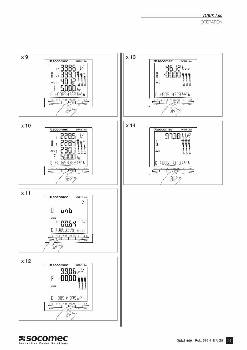
45DIRIS A60 - Ref.: 536 418 A GB
DIRIS A60
OPERATION
x 13
x 12
x 10 x 14
x 9
x 11

46 DIRIS A60 - Ref.: 536 418 A GB
x 3
x 1
x 2
x 4
x 13
x 21
DIRIS A60
OPERATION

47DIRIS A60 - Ref.: 536 418 A GB
DIRIS A60
OPERATION
x 1
x 2
x 3
x 5
x 6
x 7
x 4 x 8

48 DIRIS A60 - Ref.: 536 418 A GB
DIRIS A60
CONNECTION TEST FUNCTION
During the test, the DIRIS must have current and voltage for each of the phases. In addition to this, the function recognises the PF of the installation as being between 0.6 < PF < 1. If the PF of the installation is not within this range, this function cannot be used.In 4 BL/3 BL/2BL/1 BL, the connection of the CTs is controlled only.In 4NBL and 3NBL the connection as a whole is controlled.Do check that these are the right conditions: Err 0 = no errorErr 1 = CT phase 1 invertedErr 2 = CT phase 2 invertedErr 3 = CT phase 3 invertedErr 4 = V1 and V2 voltages invertedErr 5 = V2 and V3 voltages invertedErr 6 = V3 and V1 voltages invertedFor the Err 1, Err 2 and Err 3, the modification can be performed automatically by the DIRIS or manually by correcting the current connections.For the Err 4, Err 5 and Err 6 the modification must be performed manually by correcting the voltage connections.
x 13 sec.

49DIRIS A60 - Ref.: 536 418 A GB
Example : tEsT Err 0
x 13 sec.
x 13 sec.
DIRIS A60
CONNECTION TEST FUNCTION

50 DIRIS A60 - Ref.: 536 418 A GB
Example : tEsT Err 2
x 13 sec.
x 1
x 1
x 1
x 1 3 sec
DIRIS A60
CONNECTION TEST FUNCTION

51DIRIS A60 - Ref.: 536 418 A GB
DIRIS A60
CONNECTION TEST FUNCTION
> second test operation This menu is displayed if the product has already been tested. You can run a full test again as explai-ned below.
x 13 sec.
x 1
x 1

52 DIRIS A60 - Ref.: 536 418 A GB
• Device Switched off Check auxiliary supply
• Backlight switched off Check backlight configuration in set up menu (p. 24)
• Voltage = 0 Verify the connections
• Current = 0 or incorrect Verify the connections Verify the configuration of CT’s in set up
• Powers, power-factor and energies false Use the test connection function (p. 48)
• Phases missing on Display Check the Network configuration (in set up menu) (p. 13)
DIRIS A60
ASSISTANCE

53DIRIS A60 - Ref.: 536 418 A GB
DIRIS A60
CARACTÉRISTIQUES TECHNIQUES
CASEDimensions: 97 x 97 x 80 mm 97 x 97 x 80 mm with all optional modules (DIN 43700)Connection: via 2.5 mm2 disconnectable terminals (voltage and others) and 6 mm2 fixed terminals (current)IP index: IP52 (front panel) and IP30 (case)Weight: 465 gr.
DISPLAYType : Backlit LCD display
MEASUREMENTSThree-phase (3 or 4 wires), two-phase (2 wire) and single-phase networksVOLTAGE (TRMS)Direct measurement: from 50 to 690 V AC (phase/phase) from 28 to 400 V AC (phase/neutral)Measurement via PT: • Primary: up to 500 kV • Secondary: 60, 100, 110, 115, 120, 173 and 190 V ACDisplay and resolution from 0 to 500.0 kVPermanent overload: 760 V ACUpdate period: 1 secondCURRENT (TRMS)Via CT with: • Primary: up to 10000 A • Secondary: 1 or 5 AMinimum measuring current 3mA with U ( Ph/N ) > 28 VACInput consumption: < 0.3 VADisplay: from 0 to 11 kA (1.1 times the primary value)permanent overload: 10 Aintermittent overload: 10 In / 1 secondUpdate period: 1 secondMaximum ratio KI x KU: 10 000 000POWER Total: 0 to 8000 MW/Mvar/MVAUpdate period: 1 secondFREQUENCY from 45,0 to 65,0 HzUpdate period: 1 second
PULSE INPUT110 to 400 V AC 50/60 Hz ± 10 %120 to 350 V DC ± 20 %12 to 48 V DC -6 % / + 20 %Consumption : < 10 VA
ALIMENTATION AUXILIAIRE IEC / CEForward voltage max. 30 V DCForward voltage min. 10 V DCReverse voltage max. 30 V DCGalvanic insulation 3 kVMinimum pulse width 1sMax number of manoeuvres 108

54 DIRIS A60 - Ref.: 536 418 A GB
CONFORMITE IEC 61557-12 Edition 2 (07/2008)
PMD CHARACTERISTICSType of specification Examples of possible
specification valuesOther additional characteristics
Supply quality evaluation function (optional) - -
PMD classification SD -Setpoint K55 -Humidity + Altitude - - Operating performance class for active power or active energy (if function available) 0,5 -
CHARACTERISTICS OF THE FONCTIONSSymbol of the functions Measurement range Operational performance category,
in accordance with CEI 61557-12 depending on the KI
Other additional characteristics
P 1% to 120% In 0,5 -Qa, Qv 1% to 120% In 0,5 -Sa, Sv 1% to 120% In 1 -Ea 0 to 99999999 kW/h 0,5 -Era, Erv 0 to 99999999 kVar/h 2 -Eapa, Eapv 0 to 99999999 kW/h 1 -f 45 to 65 Hz 0,1 -I 5% to 120% In 0,2 -In, Inc 5% to 120% In 0,2 CalculatedU 50 to 600Vac ph/ph 0,2 30 to 350Vac Ph/nPFa ,PFv 0,5ind to 0,8cap 0,5 -Pst, Plt Unavailable function on A60Udip 5 to 100% Un 0,5 -Uswl 100 to 120% Un 0,5 -Utr Unavailable function on A60Uint Unavailable function on A60Unba Unavailable function on A60Unb Unavailable function on A60Uh Fn = 50Hz - rank 1 to 41 1 -THDu Fn = 60Hz - rank 1 to 35 1 -THD-Ru Unavailable function on A60Ih Fn = 50Hz - rank 1 to 55 1 -THDi Fn = 60Hz - rank 1 to 51 1 -THD_Ri Unavailable function on A60Msv Unavailable function on A60
DIRIS A60
CARACTÉRISTIQUES TECHNIQUES

55DIRIS A60 - Ref.: 536 418 A GB
CE MARKINGDIRIS A60 COMPLIES WITH THE EUROPEAN GUIDELINES FOR: • ELECTROMAGNETIC COMPATIBILITY NO. 2004/108/CE DATED 15 DECEMBER 2004. • LOW VOLTAGE NO. 2006/95/CE DATED 12 DECEMBER 2006.
CLIMATEOPERATING-TEMPERATURE RANGE: IEC 60068-2-1/IEC 60068-2-2 -10 °C to +55 °CSTORAGE TEMPERATURE RANGE: IEC 60068-2-1/IEC 60068-2-2 -20 °C to +70 °CHUMIDITY: IEC 60068-2-30 - 95 % HRSALING FOG: IEC 60068-2-52 - 2,5 % NaCl
MECHANICAL CHARACTERISTICSVibration from 10 AND 100 HZ : IEC 60068-2-6 - 2 G
INSULATIONELECTRIC SECURITY: IEC 61010-1INSTALLATION CATEGORY: III (300VAC PH/N)DEGREE OF POLLUTION: 2
CHARACTERISTICS OF THE “EVALUATION FUNCTIONS OF THE QUALITY OF SUPPLY”Symbol of the functions Measurement range Operational performance category,
in accordance with CEI 61557-12 depending on the KI
Other additional characteristics
f 45 to 65 Hz 0,1 -I 5% to 120% In 0,2 -In, Inc 5% to 120% In 0,2 CalculatedU 50 to 600Vac ph/ph 0,2 30 to 350Vac Ph/nPst, Plt Unavailable function on A60Udip 5 to 100% Un 0,5 -Uswl 100 to 120% Un 0,5 -Uint Unavailable function on A60Unba Unavailable function on A60Unb Unavailable function on A60Uh Fn = 50Hz - rank 1 to 41
Fn = 60Hz - rank 1 to 35 1 -
Ih Fn = 50Hz - rank 1 to 55Fn = 60Hz - rank 1 to 51 1 -
Msv Unavailable function on A60
DIRIS A60
CARACTÉRISTIQUES TECHNIQUES

56 DIRIS A60 - Ref.: 536 418 A GB
DIRIS A60
GLOSSARY OF ABBREVIATIONS
1BL Single-phase network, 2 fils avec 1 TC 2BL Two-phase network, 2 fils avec 1 TC 3BL Balanced three-phase network, 3 wires with 1 TC 3NBL Unbalanced three-phase network, 3 wires with 2 or 3 TC 4BL Balanced three-phase network, 4 wires with 1 TC 4NBL Unbalanced three-phase network, 4 wires with 3 or 4 TC AUX Auxiliary supply AVG Average value bACLIt LCD start-up (U or I or Aux. Condition) Ct Current transfromers Ct In Neutral current transformer dAtA Event storingdAtE Days / months / yearsEA- Negative active power (-kWh) EA+ Positive active power (+kWh) ER- Negative reactive power (-kvarh) ER+ Positive reactive power (+kvarh) ES Apparent power (-kVAh)EXT ExternalHySt HysteresisHOUr Hour run meter HOUr Hour meter start-up (U or I or Aux. condition)INT InternalMAX Maximum mean values MAX P- Active power maximum negative mean value MAX P+ Active power maximum positive mean value MAX Q- Reactive power maximum negative mean value_A faire valider MAX Q+ Reactive power maximum positive mean value MAX S Effective power maximum mean valueMOdE PrE-POSt Ratio locating the event on the record curvesnEt Network typeNO NoP+ Positive power consumption demandP- Active power consumption demandPF Power factorQ+ Positive reactive power consumption demandQ- Negative reactive power consumption demandrSET ResetSAG Voltage dipSErI Serial number SOFt Software versionSWELL OvervoltagetAn PHI PHI tangentTHD I Current harmonic distortion rate THD In Neutral current distortion rate THD U Phase-to-phase voltage distortion rate THD V Phase-to-neutral voltage distortion ratetIME Hours / minutes / secondstIME Synchronisation periodtIME 4I Integration times for mean and maximum current values tIME F Integration times for mean and maximum frequency values tIME P/Q/S Integration times for mean and maximum power values tIME U Integration times for mean and maximum voltage valuesTOP Synchronizing pulsesunb UnbalanceUt Voltage transformerU nOM Nominal voltageUt PR Voltage transformer primary Ut SE Voltage transformer secondaryYES
Hour run meter

57DIRIS A60 - Ref.: 536 418 A GB
DIRIS A60
NOTES

58 DIRIS A60 - Ref.: 536 418 A GB
NOTES
DIRIS A60

59DIRIS A60 - Ref.: 536 418 A GB
DIRIS A60
NOTES

SOCOMEC - Ref.: 536 418 A GB - 09/09
This document is not a contract. SOCOMEC reserves the right to modify features without prior notice in view of continued improvement.
H E A D O F F I C ESOCOMEC GROUPS.A. SOCOMEC capital 11 302 300 R.C.S. Strasbourg B 548 500 149B.P. 60010 - 1, rue de Westhouse - F-67235 Benfeld Cedex - FRANCE
I N T E R N A T I O N A L S A L E S D E P A R T M E N TSOCOMEC1, rue de Westhouse - B.P. 60010 F - 67235 Benfeld Cedex - FRANCETel. +33 (0)3 88 57 41 41 - Fax +33 (0)3 88 74 08 [email protected]
www.socomec.com
DIR
IS 5
61 B
/ Q
UA
T N
OT
3i