operating manual spectron 1430 dash hmd test system
TRANSCRIPT

OPERATING MANUAL
SPECTRON 1430 DASH HMD TEST SYSTEM
1430 DASH
April 2002
Spectron Engineering, Inc.
Denver, Colorado


The Spectron 1430 DASH HMD Test System Contents 1
Table of Contents Chapter One - Overview 1430 DASH Display Analysis System ..................................................................... 1-1 1430 DASH System Modules.................................................................................... 1-1 Controller ..................................................................................................... 1-2 Transport ..................................................................................................... 1-3 Main Camera 1-4 Camera (WFOV Viewfinder) ............................................................................... 1-6 Camera (IFOV Viewfinder).................................................................................. 1-7 Joystick/Video Positioning Console..................................................................... 1-7 Secondary Emergency Stop Box .......................................................................... 1-9 Video Display of Test Results ............................................................................. 1-9 Automated versus Manual Test Mode ................................................................. 1-10 Factory Calibration of the 1430 DASH System ................................................... 1-10 On-Site Alignment .............................................................................................. 1-11 Ancillary Equipment ........................................................................................... 1-11 1430-HMD-MR-01 System Mount Rack ....................................................... 1-11 Custom UUT Holding Fixtures ...................................................................... 1-11 1430 DASH System Alignment Tools ........................................................... 1-12 Custom Interface and Testing Programs......................................................... 1-12 Testing Configurations ............................................................................................. 1-12 About HMD Display Sources ................................................................................... 1-13 Display Testing 1-13 What the System Actually Measures ........................................................................ 1-14 Line Width ..................................................................................................... 1-14 Line Center ..................................................................................................... 1-14 Line Sharpnes (Modulation Transfer Factor—MTF)........................................... 1-15 Peak Brightness .................................................................................................... 1-15 Area Brightness .................................................................................................... 1-15 Parallax ..................................................................................................... 1-15 Application of System Measurements to Large Scale Testing.................................. 1-15 Geometric Distortion ............................................................................................ 1-16 Resolution ..................................................................................................... 1-16 Luminance Uniformity ......................................................................................... 1-16 Position/Registration ............................................................................................ 1-16 Parallax ..................................................................................................... 1-16
April 2002

The Spectron 1430 DASH HMD Test System Contents 2
Cautions ..................................................................................................... 1-17 Focus - Effect on Line Width & Peak Brightness Measurements ................... 1-17 External Sync - Effect on Luminance Measurements ..................................... 1-17 Aperture Location - Effect on Optical Characteristics .................................... 1-17 System Warm Up............................................................................................. 1-17 Dynamic Range - Effect on Measurements ..................................................... 1-18 Dark Current Measurement ............................................................................. 1-18 Chapter Two - Initial Setup and Connections Setup Procedures 2-1 Connections ..................................................................................................... 2-2 RS232 Connection and Protocol................................................................................ 2-6 Chapter Three - Operations Initial Power Up 3-2 Built In Test (BIT) ................................................................................................ 3-2 Warm Up Recommendation ................................................................................ 3-2 On-Site Alignment..................................................................................................... 3-3 Automatic Testing 3-3 Manual Testing ..................................................................................................... 3-3 RS232 Communications Using a Dumb Terminal or Personal Computer ........................................................................................... 3-3 Two-Way RS232 Communications ................................................................. 3-4 Characters Sent by the Dumb Terminal........................................................... 3-4 Menu Descriptions................................................................................................ 3-4 Main Menu 3-4 Summary of Menu Selections and Defaults .................................................... 3-5 Main Menu Function Descriptions .................................................................. 3-6 COMMAND MODE - RS232 Operations ...................................................... 3-9 COMMAND MODE - IEEE488 Operations................................................... 3-10 Joystick/Video Console Operations...................................................................... 3-11 Chapter Four - Maintenance and Repair Maintenance ..................................................................................................... 4-1 Repair ..................................................................................................... 4-1 Troubleshooting 4-2 Factory Contact ..................................................................................................... 4-2
April 2002

The Spectron 1430 DASH HMD Test System Contents 3
Appendices Appendix A Spectron Control Language Commands Appendix B Spectron 1430 DASH System: Specifications Appendix C 1430 DASH: Theory of Operation
April 2002

The Spectron 1430 DASH HMD Test System Overview 1-1
One
OVERVIEW DISPLAY ANALYSIS SYSTEM - HIGHSPEED
1430-OMS-HMD-03 (1430 DASH) Spectron Engineering’s high-performance display analysis system (1430 DASH) has been designed from the ground up to work as a front-end data-gathering device for objectively characterizing helmet mounted display (HMD) images. It integrates high resolution optics with precision positioning and sensing devices to measure all aspects of incident photo-optic light waves generated by the image. The design is such that the image can be characterized from the pilot’s left or right eye position in real time and the data electronically stored. This enables objective comparison with previous data from the same display, with data from other display images, or with standardized criteria. 1430 DASH System Modules The 1430 DASH System is composed of certain factory calibrated modules and associated cabling as follows:
• Controller (1) PN: 1430-HC-IS-03
• Transport (2) PN: 1430-HC-XP-03
• Main Camera (3) PN: 1430-HC-CM-03
• Joystick/Video Console (4) PN: 1430-HC-JS-01
• Secondary Emergency Stop Box (5) PN: 1430-HC-ES-02
• Calibrated Aperture Set (6) PN: 1430-HMD-AS-01
• DASH 100 Pin Control Cable (6) PN: 1430-HMD-WCO1
• Viewfinder Cameras Cable (7) PN: 1430-HMD-WVF1
• Joystick/Video Cable (8) PN: 1430-HMD-WJS1
• Power cord (10) PN: 1430-HMD-WPC1
The principle components are described briefly below; all components are described in detail in Chapter 2.
April 2002

The Spectron 1430 DASH HMD Test System Overview 1-2
Controller
Controller - Front View
The Controller is the electronic heart of the 1430 DASH System. It contains a micro-processor based dedicated controller, firmware, RAM memory, analog and digital sections, power amplifiers, and video and data communications capability. In addition, the controller contains a Front Panel monitor that reflects the controller video output from the 1430 DASH System.
When the Controller is turned on, it will perform a self-test (see BIT Test, Chapter 3) and
download the Main Camera and Transport calibration information for use in system operation.
Typically, a controlling computer will be used to send commands (see Appendix A, Spectron Control Language Commands) to the Controller through the RS232 or IEEE488 port, and the test results from the command are passed back to the controlling computer to be stored or processed in accordance with user developed test procedures. Manual testing can be accomplished with the 1430 DASH Main Menu system by connecting a dumb terminal (DT) or a personal computer (PC) to the RS232 port. When the system is initially powered up or reset, the Main Menu will be displayed on the Front
April 2002

The Spectron 1430 DASH HMD Test System Overview 1-3
Panel monitor on the Controller. Although it is not necessary for operations, the operator may find it convenient to attach an external monitor and/or video recorder to the RS170 connection on the Controller Back Panel if extensive manual testing is to be done. Transport
Transport and Camera
The Transport is the mechanical heart of the 1430 DASH System. It contains the Main Camera (described below) and the mechanical apparatus that precisely moves the Main Camera and precision periscopic mirror to allow image measurements to be made from the pilot’s eye position within a helmet. There are other distinct mechanisms involved in positioning and measurement with the 1430 DASH System. First, there is the precise linear positioning of the mirror in the X, Y and Z axis. This can be equated to locating the pilot’s eyeball position within the helmet or with respect to the image if an actual helmet is not used.
April 2002

The Spectron 1430 DASH HMD Test System Overview 1-4
The transport mechanism allows approximately 3.5” of travel in the X and Y axis. Z axis movement is approximately 3.3”. Precise factory calibration and correction of the linear encoders allows the Transport to achieve position repeatability of .001” within the X, Y, and Z range of movement. Second, there is the horizontal and vertical rotation of the mirror. This can be equated to the rotation of the pilot’s eyeball in its socket to view various aspects of an image within the field of view (FOV). The mirror pivot mechanism allows for measurement within a vertical FOV (altitude) of approximately 70°. The mirror rotational mechanism allows for measurement within a horizontal FOV (azimuth) of approximately 270°. Precise factory calibration and correction of the rotary encoders allows the Transport to achieve repeatability factors of .006° in altitude and azimuth measurements of image parameters within the respective FOV. Third, there is a sixth axis of precision movement, however, that involves the Main Camera focus plane and is addressed in the Main Camera overview directly below. There is an Emergency Stop Button located on the rear of the Transport. It functions as fully described in Joystick/Video Positioning Console, Item 8 below. Main Camera The Main Camera module consists of a high-quality, autofocus photo-diode matrix array camera. Although the Main Camera is factory removable for replacement, it is generally left permanently mounted in the Transport during field operations. The precise control of the Main Camera position afforded by the Transport module, along with the Factory calibrated and corrected focal plane of the photo-diode matrix array within the Main Camera, allows the Main Camera to function as an automated theodolite. In addition, the detector has been tested to have zero defective pixels, tested for photometric linearity, and each pixel of the detector is calibrated and corrected for dark sensitivity errors. Thus, the Main Camera can be considered an “imaging microphotometer” as well as an automated theodolite. The autofocus feature of the Main Camera is important because the display image being tested may not actually be at infinite focus. Most image characteristics are best quantified with the Main Camera automatically focused on the actual image.
April 2002

The Spectron 1430 DASH HMD Test System Overview 1-5
Interchangeable Apertures
The Main Camera is equipped with 2 neutral density (ND) filters, 3 RBG Color filters, and 4 Apertures that may be utilized to improve the performance of the 1430 DASH System for a given display image or for a particular user required measurement. The ND1 filter passes 10% of the available light to the detector and the ND2 filter passes 1% for use with extremely bright images. It should be noted that the location of the factory supplied apertures is critical to the factory calibration factors stored in the Main Camera. The utilization of user supplied apertures at a different point along the image axis may adversely affect the optical characteristics of the image. During factory calibration, calibration information for the precision linear encoder that controls the movement of the Main Camera focus axis, information for the spectro-radiametrics of the detector, as well as other calibration constants are stored in the Main Camera and transferred to the Controller upon start-up.
April 2002

The Spectron 1430 DASH HMD Test System Overview 1-6
Camera (WFOV Viewfinder)
WFOV Viewfinder Camera
The 60° wide field of view (WFOV) Viewfinder Camera is fixed at the end of the periscopic probe and is utilized in conjunction with the Joystick/Video console to easily locate an area of interest in a given image and to move the Main Camera to that general area. It should be noted that the centerline of the WFOV image is offset from the centerline of the precision mirror used by the Main Camera by approximately 0.85” along the Y axis. If only the WFOV Viewfinder Camera is used to locate an area of interest, the Main Camera may need to be shifted along the Y axis to be properly positioned in the exit pupil of the unit under test (UUT). If VFI mode is selected on the Main Camera (see Appendix A) the 1430 DASH System will automatically manage this shift as the WFOV Viewfinder Camera is selected or deselected. The image generated by the WFOV Viewfinder Camera, if selected, is viewable on both the Joystick/Video console and on a user supplied monitor attached to the RS170 output port of the Controller.
April 2002

The Spectron 1430 DASH HMD Test System Overview 1-7
Camera (IFOV Viewfinder)
IFOV Viewfinder - Selected Position
The 9° intermediate field of view (IFOV) Viewfinder Camera is a ‘flipper’ camera that can be moved into, and out of, the optical axis of the Main Camera. Because it is in the optical path of the image to the Main Camera, when selected it allows quite accurate positioning of the Main Camera to the area of interest on the image. Like the WFOV Viewfinder Camera, it is viewable on both the Joystick/Video console and on a user supplied monitor attached to the RS170 output port of the Controller. Joystick/Video Positioning Console
Joystick/Video Console
April 2002

The Spectron 1430 DASH HMD Test System Overview 1-8
The Joystick/Video Positioning Console was developed to improve the user friendliness of the 1430 DASH System during manual measurement operations. It also serves as an aid in predetermining position information that can later be inserted into software used for automatic operation. The console contains the following elements:
1. Two joysticks control Main Camera and periscopic probe movement in the X, Y, Z linear axis, or in the Altitude, Azimuth, and Focus plane, as selected by the position of the Mode Switch, below. In operation, the image will appear to move beneath a centering crosshair that is designed to locate the center of interest for Main Camera measurement if the Cross switch, below, is active.
2. The TFT Active Matrix Display, if selected by the Display Switch, below, will display one of 3 Camera images as selected by the Camera Switch, below. The display tilts for proper viewing angle, and Bright, Color, and Contrast adjustment thumbwheels are located on the lower right rear corner of the Console. There is an additional thumbwheel located on the front center panel of the Console that controls the shading of the crosshair.
3. The Mode Switch is a three position switch that controls the axis affected by joystick movement. It is either OFF, or moved to select one of the two above referenced groups of movements permitted by joystick control.
4. The Move Switch functions only in conjunction with the DASH position on the Camera Switch and the graphics mode of operation of the Controller (see 7 below). It has no function when either Viewfinder Camera is selected. It is a two position switch that controls the rate of movement of the DASH Main Camera system when DASH is selected on the Camera switch and the joysticks are activated.
5. The Display Switch is a momentary push-button switch that toggles the video display ON/OFF on the Joystick/Video Console.
6. The Cross Switch is a three position switch that controls the appearance of the joystick controlled crosshair. The crosshair may be selected OFF, Solid, or Gap. The Solid position shows the crosshair junction and the Gap position shows an opening at the junction of the crosshair. The crosshairs of the WFOV Viewfinder, IFOV Viewfinder, and DASH camera are factory adjusted to be coincident.
7. The Camera Switch controls which of three camera images will be displayed on the console video and on the RS170 Monitor, if attached. Selecting the WFOV position displays the view from the WFOV Camera fixed at the end of the periscopic probe and described above. If the 1430 DASH System has been placed in VFI mode, see Appendix A, the Main Camera will shift 0.85” along the Y axis when the WFOV Viewfinder Camera is selected and return when another Camera Switch selection is made. An Emergency Stop will disable the VFI mode. Selecting the IFOV position will flip the IFOV Camera into the optical axis of the Main Camera and display the IFOV Camera image. Deselecting the IFOV Camera will move the IFOV Camera out of the Main Camera optical axis. Selecting the DASH position will
April 2002

The Spectron 1430 DASH HMD Test System Overview 1-9
display the 1430 System Controller output. If the graphics mode has been selected on the Controller, the image from the Main Camera will be displayed.
8. The Emergency Stop Switch on the Joystick/Video Console is one of three such switches in the 1430 DASH System. All of the Emergency Stop Switches operate in the same manner - all drive motor power to the 5 external axis of movement (X, Y, Z linear axis, and Altitude and Azimuth movement of the Main Camera and periscopic optics) is interrupted and movement on all 5 axis is halted when the switch is pressed. The Emergency Stop Switches are functional whether the 1430 DASH is being operated in automatic or manual mode.
NOTE: The precisely calibrated head of the periscopic optics can be damaged if it makes physical contact with any object during movement or operation of the 1430 System. If the operator is alert to the head movement, the Emergency Stop Switch offers an immediate solution if collision appears imminent. The eye position transport resume (IRE) command must be issued after the problem is resolved and it is desired to continue normal operations. The transports will be reenabled at their current positions. They will NOT continue to move to the previously issued command position.
Secondary Emergency Stop Box
Emergency Stop Box
The Secondary Emergency Stop Box is connected to the 1430 DASH through the Controller and is designed to be mobile. This enables it to be located in the most advantageous position for the operator during 1430 DASH System operations. The Switch functions as an emergency stop, and is described fully in the Emergency Stop Switch element of the Joystick/Video Positioning Console section directly above. Video Display of Test Results The 1430 DASH System will output messages, test results, and other communications to the Front Panel monitor. Operator convenience may be enhanced by connecting an external video monitor or recorder to the RS170 port on the Back Panel of the Controller. Either monitor may be used to monitor automatic test results and run interactive manual
April 2002

The Spectron 1430 DASH HMD Test System Overview 1-10
tests. Only the external monitor and Joystick/Video display panel will display a positioning image when using the Joystick/Video Console. Automated versus Manual Test Mode The 1430 DASH System can be programmed to run all tests on a HMD display automatically without the operator having to interact with the system or even monitor a video output. However, the operator can perform manual tests utilizing the Front Panel or external monitor and a serial terminal. Manual test commands are described in detail in Chapter 3. Factory Calibration of the 1430 DASH System Factory calibration of the 1430 DASH System is a highly precise and integrated procedure necessary to achieve the specifications set forth in Appendix B. Extremely high quality linear and rotary encoders are used at the factory to determine positional correction factors along all axis of movement within the 1430 DASH System. All positional movement calibrations are traceable to NIST standards. Factory calibration of the Transport module consists primarily of mechanical calibrations of each transport axis with its precision encoder. There is 64K resolution from the rotary encoder and ± .0001” resolution of the linear encoders. When plotted, the position output curve for even the best encoder is generally not perfectly linear. This curve must be linearized to a very fine degree in order to get the resolution needed. Correction factors are defined for each system encoder in each axis of movement to make the linearity of that encoder more correct than when received from the manufacturer. This provides greater precision for Main Camera movement and more confidence that the Main Camera is actually measuring where the operator thinks it is measuring. This method of calibration includes analyzing a grid and test data which is then fed into a table and used to correct the characteristics of each encoder. The corrections, made for each unit, are permanently stored in EEPROMs and are used by the Controller during operations to accurately correct the encoder output. This calibration cannot be adjusted by the customer. Every Transport and every Main Camera carries its specific factory calibration information in EEPROMs. Of importance for both positional and luminance accuracy is the Main Camera factory calibration. The Main Camera detector has been tested at the factory to have zero defective pixels. It is tested for photometric linearity, and each pixel of the detector is calibrated and corrected for dark sensitivity errors. The focus transport mechanism of the Main Camera is calibrated similar to the Transport linear axis above. Correction factors are stored and utilized during 1430 DASH System operation to maximize the accuracy of auto-focus measurements and for luminosity measurements both for no filter operation, and for ND or Color filter operations.
April 2002

The Spectron 1430 DASH HMD Test System Overview 1-11
Because the 1430 DASH is calibrated at the factory as an interdependent system, no attempt to open or repair any of the modules should be made in the field as the validity of the calibration data will be compromised. This includes replacement of circuit boards within the Controller. Instead, return the System to Spectron Engineering in Colorado for service or arrange for factory calibration on-site by Spectron. On-Site Alignment Some on-site alignment procedure should be accomplished when the system is initially set up. On-site alignment will ensure that the 1430 DASH System is measuring relative to a known reference point. Spectron can supply alignment tools to be used with the 1430 DASH System on an optional basis. If user supplied alignment tools are used to check alignment or to develop a coordinate system of measurement, it should be noted that unless the principal reference point is traceable to NIST standards the positional measurement performance of the 1430 DASH System may be degraded from factory specifications. Ancillary Equipment Spectron can supply the following additional accessories for the 1430 DASH System:
1430-HMD-MR-01 System Mount Rack
The optional System Mount Rack allows the 1430 DASH System to be operated in the horizontal or vertical position as a convenience to the operator in allowing best access to the unit under test (UUT).
Custom UUT Holding Fixtures
The 1430 DASH Inspection System is usually combined with specific fixturing equipment so that the Transport and Main Camera are mounted specifically to hold the equipment being tested in a known and exact relationship to the Main Camera. Spectron Engineering designs specific fixtures and fixture
April 2002

The Spectron 1430 DASH HMD Test System Overview 1-12
combinations to hold the device being tested in an optimal position for measurement. Accurate and repeatable fixturing is essential to efficient testing of display devices.
1430 DASH System Alignment Tools
Spectron Engineering designs specific collimating devices for field use in aligning the 1430 DASH System to a user-required coordinate system. The Alignment Tools are designed to align the system to the particular holding fixture in use or to an absolute reference depending upon particular user requirements.
Custom Interface and Testing Programs
Increasing the clarity and number of results obtained per each user input is an important aspect of user friendly operation of the 1430 DASH System. Spectron has developed a LabVIEW® compatible set of drivers for the 1430 DASH System. The drivers have been approved and posted on National Instruments’ web site (www.natinst.com) under the company name Spectron Engineering, GPIB driver Dash 1430-OMS-HMD-01. Spectron will design and supply an intuitive and user friendly interface to the 1430 DASH System based upon a particular user need that will allow for efficient and effective manual measurement and testing of displays. In addition, Spectron will develop an automatic test procedure based upon user requirements and the necessary subset of commands required to completely characterize a given display image.
Testing Configurations HMDs may be designed as holographic (three-dimensional binocular) or flat (two-dimensional monocular) displays. The HMD projects important aircraft instrument data and external simulation data into the field of view of the pilot at a focal point simulating infinity, which allows the pilot to look at the information on the HMD without changing the focus of his/her eye. Holographic HMDs and other infinity-focus display images cannot be accurately measured with simple x-y test systems. This particular adaptation of Spectron’s optical test system, the 1430 DASH System, simulates the human eye in order to test the reliability or integrity of a HMD. Specifically, this system simulates the eye of a pilot as he or she looks through the helmet visor at the generated image and can be precisely moved to capture the image parameters as viewed from the left and right eye. This is of particular significance to the proper characterization of binocular displays.
April 2002

The Spectron 1430 DASH HMD Test System Overview 1-13
About HMD Display Sources HMDs utilize a class of nearly monochromatic high-brightness CRTs, developed specifically for cockpit applications. The light output is high intensity, but it is filtered. Typically these are green phosphor CRTs with a narrow spectral range, peaking at 548 nanometers with only an 18nm bandwidth. The limited range allows the use of sophisticated contrast enhancement filters to handle the various back-light situations in an aircraft. The 1430 DASH System Main Camera is equipped with 2 neutral density (ND) filters, 3 RBG Color filters, and 4 Apertures that may be utilized to improve the performance of the 1430 DASH System for a given display image or for a particular user required measurement. It should be noted that the location of the factory supplied apertures is critical to the factory calibration factors stored in the Main Camera. The utilization of user supplied apertures at a different point along the image axis may adversely affect the optical characteristics of the image. The HMD image may be generated from either a stroke or raster-type source. The stroke source produces a more intense, higher resolution line than the television-like raster type. The 1430 DASH System can test either type of source.
Display Testing Prior to the Spectron 1430 DASH System, single-point, or x-y, detectors were used to test HMDs. As the name suggests, that type of detector looks at only one point on the display at a time; thus, some display faults may be missed, such as flickering or a slowly moving or out of focus line. The Spectron 1430 DASH System provides the advantage of real-time testing over the entire display. The Spectron 1430 DASH System has the capability for remarkable accuracy when testing a display, but in some applications the equipment is restrained because it is testing a visual display across a very narrow wavelength band. For instance, the lines in a display image could be oscillating (waving back and forth); however, the human eye can only detect this type of oscillation when it occurs with a frequency less than one-tenth of a second. Therefore, the 1430 DASH System utilizes a selectable acquisition time to measure absolute intensity and resolution; that is, the system can increase or decrease the integration time to capture the required data. The Main Camera can measure brightness from 0.2 to 12,000 ft.-lamberts.
April 2002

The Spectron 1430 DASH HMD Test System Overview 1-14
What the System Actually Measures The 1430 DASH System can perform a variety of tests in each configuration, measuring:
_ line width and resolution _ line center _ line sharpness (Modulation Transfer Factor—MTF) _ peak brightness _ area brightness _ parallax
These tests are described in more detail below. Although the 1430 DASH System simulates the human eye, it has the capability to make measurements of absolute light emissions outside the range visible to the eye.
Line Width
The Main Camera can measure line widths from a maximum of ~1.2 degrees to a minimum of ~0.05 degrees. This is limited on the high side by the field of view and on the low side by the pixel pitch of the detector. Lines smaller than 0.05 degrees can be measured, at reduced accuracy, down to the absolute limit of ~0.015 degrees. The Line Width can be calculated using a single row of pixels across the line or an average of 16 or 64 lines of pixels. Averaging has the advantage of increasing the accuracy of the measurement but can be misleading if the line is not perpendicular to the detector axes. See the LINE command for details.
Line Center
Line Center measurement is a composite measurement in the 1430 DASH System. The position of a line in the Main Camera field of view is mathematically combined with the position of the Altitude and Azimuth transports to get the final angular position of the line. The Line Center can be calculated using a single row of pixels across the line or an average of 16 or 64 lines of pixels. Averaging has the advantage of increasing the accuracy of the measurement but can be misleading if the line is not perpendicular to the detector axes. (See LINE command, Appendix A, for details).
April 2002

The Spectron 1430 DASH HMD Test System Overview 1-15
Line Sharpness (Modulation Transfer Factor—MTF)
The MTF of a displayed line is based on luminance and is calculated from the formula 100 * (Max-Min)/(Max+Min).
Peak Brightness
The Peak Brightness is a measurement of the luminance intensity of a line. The brightest point in the cross section profile of the line is reported using all of the luminance correction factors. The Peak Brightness can be calculated using a single row of pixels across the line or an average of 16 or 64 lines of pixels. Averaging has the advantage of increasing the accuracy of the measurement but can be misleading if the line is not perpendicular to the detector axes. (See LINE command, Appendix A, for details).
Area Brightness
The Area Brightness may be a more accurate measurement of display luminance than Peak Brightness because phosphor granularity and other variations can be averaged. However the entire area being sampled must be illuminated for effective measurement. The size of the area being sampled is user selected. (See AREA command, Appendix A, for details).
Parallax
Parallax is a measurement of the angular shift in the position of a line when the viewers eye position is moved laterally. Parallax is an indication of the apparent distance to the image. An image at an infinite distance will exhibit zero parallax. A parallax measurement in the 1430 DASH System is performed by an internal sequence of measurements: a Line Center, a shift in X or Y position, another Line Center and a return to the original X or Y position.
Application of System Measurements to Large Scale Testing Large scale testing is usually accomplished by an automated procedure that is constructed by combining a series of the above measurements. All of the data that is returned by the 1430 DASH System should be written to a data file where it may be accessed and used to confirm questionable measurements. For example, if a line position or line width does not appear correct, upon checking the data it may be discovered that the peak brightness was zero at a particular position. That would indicate that there was no real line in view at that position.
April 2002

The Spectron 1430 DASH HMD Test System Overview 1-16
Geometric Distortion
Geometric distortion is a standard feature of a CRT, pin cushion, barrel etc. HMD optical systems can also introduce distortions which may need to be characterized and corrected. A matrix of Line Center, Line Width, and Peak Brightness measurements can accumulate enough data to measure the distortion pattern and derive a correction.
Resolution
The electrical focus of the lines on a CRT may vary with deflection. The change in line width over the field of view may indicate a need for a dynamic focus voltage correction. The user should ascertain that a variation in optical focus is not interpreted as electrical focus.
Luminance Uniformity
The variation of luminance over the display field can be tested using either Peak Brightness or Area Luminance measurements. If using peak brightness, it should be determined that a variation in optical focus is not causing a lowered peak luminance or a wider line.
Position/Registration
In a binocular HMD, all of the corrections must be applied to each of the display line positions, then the data taken from the two images should be compared for registration and eye convergence.
Parallax
Data measurements for parallax over the entire display field for both vertical and horizontal lines can be taken and analyzed. This will reveal the optical focus variations and astigmatism found in the display image.
April 2002

The Spectron 1430 DASH HMD Test System Overview 1-17
Cautions Observing the following cautions will prevent many of the common causes of erroneous data being derived from the 1430 DASH System.
Focus - Effect on Line Width & Peak Brightness Measurements
When measuring lines, the Line Width and Peak Brightness are related. If the optical focus is not optimized a line will appear to be wider and less bright than when sharply focused. For a range near focus, the product of the (line width * peak brightness) is fairly constant.
External Sync - Effect on Luminance Measurements
When measuring a display where the image is updated on a periodic basis, it is important to use the external sync input to the 1430 DASH System. This causes the camera to take scans synchronized to the image retrace. When using the sync, the camera will integrate the light from the same number of display rewrites. Failure to use the sync can result in luminance errors of 30% for a short integration. The error will decrease with longer exposure times. Line Center and Line Width measurements are not affected.
Aperture Location - Effect on Optical Characteristics
The position of the aperture has an effect on the Line Center accuracy of the system. Changing the aperture position will change the scale factor of the image on the detector. A Line Center error, proportional to the offset of the image from the detector centerline, will result.
System Warm Up
The 1430 DASH System should be allowed to warm up for at least 20 minutes before critical measurements are taken. The detector in the Main Camera is thermoelectrically stabilized. The detector and surrounding thermal masses need to reach equilibrium for maximum accuracy. In addition, if a system reset is performed, another warm up is required. After the warm up period, perform a DARK command. (See DARK command, Appendix A, for details).
April 2002

The Spectron 1430 DASH HMD Test System Overview 1-18
Dynamic Range - Effect on Measurements
Line Center measurements may be taken at low dynamic range without effecting the accuracy of the 1430 DASH System. Luminance and line width measurements however, may require a higher light level for stable readings. A dynamic range of 50% or greater would be desirable.
Dark Current Measurement
A Dark Current measurement for each pixel, is automatically performed whenever the Gain is changed. The dark current is subtracted from the exposure. This results in the energy attributable to the light from the image being measured for each pixel. Another DARK should be performed before taking a series of critical luminance measurements or if more than 15 minutes has elapsed since the last DARK. (See DARK command, Appendix A, for details).
April 2002

The Spectron 1430 DASH HMD Test System Initial Setup and Connections 2-1
Two
Initial Setup and Connections 1430-OMS-HMD-03 (1430 DASH)
The 1430 DASH System is composed of three main modules (Transport, Main Camera, Controller), a Joystick/Video Console, a Secondary Emergency Stop Box, a Calibrated Aperture Set and associated cabling. The theory behind the function of each module was discussed in Chapter 1. Below we describe how each module is set up and connected for normal operation. The following units and cables should be located and accounted for:
• Controller (1) PN: 1430-HC-IS-03
• Transport (2) PN: 1430-HC-XP-03
• Main Camera (3) PN: 1430-HC-CM-03
• Joystick/Video Console (4) PN: 1430-HC-JS-01
• Secondary Emergency Stop Box (5) PN: 1430-HC-ES-02
• Calibrated Aperture Set (6) PN: 1430-HMD-AS-01
• DASH 100 Pin Control Cable (7) PN: 1430-HMD-WCO1
• Viewfinder Cameras Cable (8) PN: 1430-HMD-WVF1
• Joystick/Video Cable (9) PN: 1430-HMD-WJS1
• Power cord (10) PN: 1430-HMD-WPC1
Setup Procedures Carefully unbolt the 1430 DASH Transport (1430-HC-XP-03) and factory installed Main Camera (1430-HC-CM-03) and remove it from the shipping carton. If the unit is to be used in the horizontal position, mount the unit securely on the optical bench where it will be used in operation. If the unit is supplied with the optional System Mount Rack (1430-HMD-MR-01) and the unit will be operated in the vertical position, the unit may be mounted on the floor. Remove the clamps that secure and protect each linear axis from movement during shipping. Remove the Controller from its shipping container and place it near the 1430 DASH Transport and Camera assembly. The Controller should be placed in a secure location that will allow the unit to be connected to the 1430 DASH Transport and Camera assembly with the supplied DASH 100 Pin Control Cable and that will allow the Secondary Emergency Stop Box to be located near the operator.
April 2002
The Spectron 1430 DASH HMD Test System Initial Setup and Connections 2-2
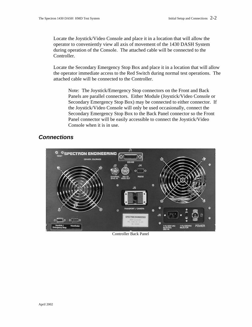
Locate the Joystick/Video Console and place it in a location that will allow the operator to conveniently view all axis of movement of the 1430 DASH System during operation of the Console. The attached cable will be connected to the Controller. Locate the Secondary Emergency Stop Box and place it in a location that will allow the operator immediate access to the Red Switch during normal test operations. The attached cable will be connected to the Controller.
Note: The Joystick/Emergency Stop connectors on the Front and Back Panels are parallel connectors. Either Module (Joystick/Video Console or Secondary Emergency Stop Box) may be connected to either connector. If the Joystick/Video Console will only be used occasionally, connect the Secondary Emergency Stop Box to the Back Panel connector so the Front Panel connector will be easily accessible to connect the Joystick/Video Console when it is in use.
Connections
Controller Back Panel
April 2002

The Spectron 1430 DASH HMD Test System Initial Setup and Connections 2-3
Controller Front Panel
The Controller is a micro processor based dedicated controller that includes several interfaces that are not required for testing, but in some cases may make testing easier and allow interactive testing. These interfaces are:
o IEEE488 or GPIB interface (J1 on back panel) This interface connector is located on the back panel of the Controller.
This enables the controlling computer to communicate with the 1430 DASH System using Spectron Control Language Commands (Appendix A).
o RS232 Serial Interface (J4 on back panel) This interface, located on the back panel of the Controller, allows two-
way serial communication between the 1430 DASH System and a dumb terminal or other RS232 device. This serial interface is also used for factory calibration and checkout.
o RS170 CRT Output (J3 on back panel) This connection is a video output used to display test results and
command menus on an external monitor.
April 2002

The Spectron 1430 DASH HMD Test System Initial Setup and Connections 2-4
o External Sync Input (J2 on back panel) This interface allows the operator to toggle between external and internal
sync. You can supply this sync input to synchronize with a vertical sync pulse from the display system that is undergoing test. Using the external sync function should improve the performance and consistency of analysis functions of external displays.
Note The system can function without an external sync, but the system will not work at all if there is no external sync present and the system is in the external sync mode.
Cables to operate the above circuits are not supplied with the 1430 DASH System. The Camera is shipped installed on the Transport from the factory and is electrically connected to the Transport through two DB25 connectors. These connectors should never be disconnected in the field., Connect the DASH 100 Pin Control Cable from the Controller (J5) to the back of the Transport. The 100 pin connector is a zero insertion force connection that is keyed to allow insertion only in the proper manner. The cable is symmetrical and either end may be connected to the Controller or Transport. During operation, the connector must be locked in place with the connector Locking Handle on both the Controller and Transport. Whenever the DASH 100 Pin Control Cable is disconnected, install the tethered protective cover immediately to prevent accidental damage to the connector pins.
April 2002

The Spectron 1430 DASH HMD Test System Initial Setup and Connections 2-5
DASH 100 Pin Control Cable - Viewfinder Cameras Cable
Connect the Viewfinder Cameras Cable between the Controller and the small connector box on the periscopic arm of the Transport. The cable has Male/Female 15 pin, high density subminiature “D” connectors. The MALE connector on the cable connects to the described Transport connector box. The FEMALE connector on the cable connects to the lower left connector on the Controller Back Panel labeled “Viewfinder”.
Joystick/Video Cable
Connect the Joystick/Video Cable between the Joystick/Video Console and the Controller. The cable has Male/Female 15 pin, high density subminiature “D” connectors. The MALE connector on the cable may either be connected to the Controller on the lower right connector of the Front Panel labeled
April 2002

The Spectron 1430 DASH HMD Test System Initial Setup and Connections 2-6
“Joystick/Emergency Stop” or on the lower left connector on the Rear Panel with a similar label. The Controller connectors are parallel connectors designed for the convenience of the operator. Connect the FEMALE connector of the cable to the connector on the Joystick/Video Console.
Emergency Stop Box and Cable
Connect the attached cable on the Secondary Emergency Stop Box to the Controller using the Front or Rear Panel connection not used by the Joystick/Video connector described directly above.
Power Switch/Circuit Breaker
Lower Right Corner - Controller Back Panel Determine that the power switch/circuit breaker on the back of the Controller is in the OFF (down) position and that the 115/230 VAC selector switch is in the correct position for the power source to be used. Connect the Power cord to the back of the controller (J6) and plug into the power outlet. The system is powered up by turning on the power switch/circuit breaker on the back of the Controller and operated according to the procedures in Chapter 3 of this manual.
RS232 Connection and Protocol
User supplied and initiated RS232 Communications with the 1430 DASH System are described in Chapter 3. The following information is supplied as an aid in initiating proper communications through the RS232 port.
April 2002
The Spectron 1430 DASH HMD Test System Initial Setup and Connections 2-7
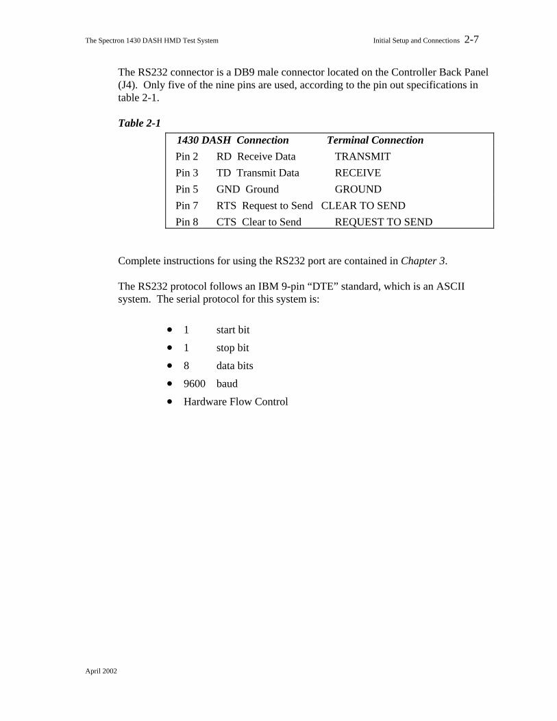
The RS232 connector is a DB9 male connector located on the Controller Back Panel (J4). Only five of the nine pins are used, according to the pin out specifications in table 2-1.
Table 2-1
1430 DASH Connection Terminal Connection Pin 2 RD Receive Data TRANSMIT Pin 3 TD Transmit Data RECEIVE Pin 5 GND Ground GROUND Pin 7 RTS Request to Send CLEAR TO SEND Pin 8 CTS Clear to Send REQUEST TO SEND
Complete instructions for using the RS232 port are contained in Chapter 3. The RS232 protocol follows an IBM 9-pin “DTE” standard, which is an ASCII system. The serial protocol for this system is:
• 1 start bit
• 1 stop bit
• 8 data bits
• 9600 baud
• Hardware Flow Control
April 2002

The Spectron 1430 DASH HMD Test System Operations 3-1
Three
Operations 1430-OMS-HMD-03 (1430 DASH)
The 1430 DASH System may be operated in one of three operating modes; 1) automatic mode, with command and data information controlled by user or Spectron created software, 2) menu mode, with command and data information controlled by operator selections from the built in 1430 DASH System menu software, or 3) command mode, with Spectron Control Language Commands directly entered by the operator. The menu mode is only available through the RS232 port as described below. Automatic testing and command mode are available through either the RS232 port or the IEEE488 bus on the Controller. Whether the tests are performed automatically or manually, if the Controller is not located in a position for the operator to view the Front Panel monitor, it is suggested that an external video monitor be connected to the system through the RS170 connection on the Controller and positioned to allow command and test results to be viewed in real time by the operator. The Front Panel monitor or external monitor is the only way to know immediately if the system is working properly, and when used with a personal computer or dumb terminal, provides effective capability for interactive testing. This chapter will primarily describe the operation and testing procedures for manual operation using the Main Menu system or Spectron Control Language Commands. Automatic testing may be accomplished by software that sends sequential Spectron Control Language Commands, and captures the resulting data as it is generated, according to specific test procedures for the HMD display unit under test (UUT). The function of the Joystick/Video Console, which primarily operates independently and is extremely useful in locating an area of interest to be tested in menu or command mode, will be described below.
April 2002

The Spectron 1430 DASH HMD Test System Operations 3-2
Initial Power Up
Built In Test (BIT)
Power Switch/Circuit Breaker
Lower Right Corner - Controller Back Panel
The power switch/circuit breaker is located on the back panel of the Controller near the AC cord connector. After all Setup and Connect procedures described in Chapter 2 have been completed, the power switch may be turned on This will initiate a system reset and the BIT will occur. The BIT will be accomplished each time the system is turned on or reset. It tests the electronic circuitry and function of the Controller, Transport, and Main Camera. If all modules are functioning properly, the items undergoing test will indicate ‘pass’ and the Main Menu will then be displayed. If there is a failure of a component being tested, ‘fail’ will be indicated in reverse video on that item. If able, the system will continue to function after the ‘fail’ indication and, in most instances, a short message and error number will be displayed on the Main Menu. Upon completion of the BIT, the Main Menu will be displayed on the Front Panel monitor and on the external video monitor, if connected. In manual test mode, the system is menu driven and all of the available functions are listed on the Main Menu.
Warm Up Recommendation
In order to allow all components to reach a consistent operating temperature, the 1430 DASH System should be turned on approximately 20 minutes prior to use. It is recommend that the operator take a new dark current reading after the initial warm up period by using option “D” on the Main Menu. To ensure continuous good data during normal operations, dark current readings should be taken periodically to compensate for ambient thermal variations.
April 2002
The Spectron 1430 DASH HMD Test System Operations 3-3
On-Site Alignment
After a successful Power Up, the 1430 DASH System will move the Altitude, Azimuth and Focus axis to a factory calibrated and determined Zero point. The X, Y, and Z linear axis will remain in their current positions. If the operator desires to reference a different angular coordinate system, that may be accomplished through appropriate use of the ALIGN Command. The linear coordinate system (X, Y, Z) may be offset with the ITR Command (see Appendix A).
Automatic Testing
The 1430 DASH System is capable of automatically testing a display by responding and replying to all Spectron Control Language Commands (see Appendix A) via the IEEE488 bus or RS232 port. Automatic routines for testing specific HMD devices are not included with the 1430 DASH System, however, they may be created by the user of the system or separately contracted from Spectron on an optional basis.
Manual Testing
To perform a manual test, connect a dumb terminal (DT) or a personal computer (PC) to the RS232 port on the Controller. Alternatively, a properly configured PC or control console can communicate with the Controller through the IEEE488 bus connection. Use of the IEEE488 bus will effectively override and disable the Main Menu system and the RS232 port. The 1430 DASH System includes a RS170 output on the Controller which can be attached to a video monitor or recorder. The identical output may be viewed on the Front Panel monitor of the Controller. This section will describe the relationship of the video output to what is happening in the system as various test functions are performed.
RS232 Communications Using a Dumb Terminal or Personal Computer
All of the manual testing operations, described below, can be performed via the RS232 port using a dumb terminal (DT) or a dumb terminal emulator on a PC. When learning to use the system with a DT or PC, it is important to use the Front Panel or external video monitor, and the DT or PC monitor, for comparison of responses. Any ASCII input of a valid character corresponding with one of the Menu functions described later in this chapter will cause the appropriate function to be implemented. Valid ASCII transmission characters are set forth below. Further description of the RS232 port, wiring information, and protocols are provided in Chapter 2.
April 2002

The Spectron 1430 DASH HMD Test System Operations 3-4
Two-Way RS232 Communications
All transmissions between the 1430 DASH system and a DT or PC are in ASCII code. Commands that are sent via the RS232 interface return data in their own distinct format. All transmissions to the DT or PC must be followed by a Carriage Return and a Line Feed. To begin RS232 communications, reset the system by turning on the power.
Characters Sent by the Dumb Terminal
The following ASCII codes correspond to the output from the DT or PC keyboard input:
• Characters 0-8 correspond with ASCII characters $30-$38 • Characters A-F correspond with ASCII characters $41-$46
Menu Descriptions
Main Menu
When the 1430 DASH System is initially powered up, or reset, the system Main Menu will be displayed on the Front Panel and external monitor. The Main Menu, as it appears on the monitor, is illustrated in figure 3-1; the menu functions are summarized in Table 3-1 and are described in detail on the pages that follow. Some test examples will be described. It is important to note that the Altitude, Azimuth and Focus axis of movement will revert to the factory predetermined settings at power up, or whenever the system is reset, and the X, Y, and Z linear axis will remain at their current positions. Additionally, all Menu functions return to their default settings. Menu default settings, with toggled options, are listed in Table 3-2. For numerical input and output, the 1430 DASH System utilizes floating point numerics which provides greater flexibility and accuracy, however, the operator must enter the decimal point whenever one is required. The system allows up to five digits plus a decimal point.
April 2002

The Spectron 1430 DASH HMD Test System Operations 3-5
Figure 3-1
OPTICAL MEASURING SYSTEM
0 - VERTICAL LINE ANALYSIS 1 - HORIZONTAL LINE ANALYSIS A - EXTRA WIDE LINE ANALYSIS B - SYNC TOGGLE IN D - DARK E - GRAPHICS C - ESCAPE TO THIS MENU
Table 3-1 Summary of Menu Selections and Defaults
Key Name Function Description
Setup Commands: C. Escape Return to Main Menu E. Graphic Output Gray scale setting D. Take Dark Dark current measurement B. Sync Toggle between internal and external synchronization Data Commands: 0. Vert Line Vertical line measurement 1. Horiz Line Horizontal line measurement A. EXWIDE Toggle between narrow, wide and extra
wide-line profile analysis
Note To perform a Hardware Reset, power down the system, then re-start it or Press the recessed Red RESET Button on the Front Panel.
April 2002

The Spectron 1430 DASH HMD Test System Operations 3-6
Table 3-2
Menu Selection
Default Settings
Toggled Settings
A EXTRA WIDE line profile NARROW & WIDE
line profile
B SYNC Internal SYNC External
Main Menu Function Descriptions
THE OPERATOR MUST CLOSELY MONITOR ALL AXIS OF MOVEMENT OF THE 1430 DASH SYSTEM DURING MENU OPERATIONS. BE PREPARED TO PRESS AN EMERGENCY STOP BUTTON IMMEDIATELY SHOULD IT APPEAR THAT ANY PART OF THE SYSTEM IS IN DANGER OF CONTACTING ANY PART OF THE FIXTURING OR THE DISPLAY BEING TESTED.
This section describes in detail how to use each menu function. Menu functions fall into two categories: 1) those used for setting up the system (A-E), and 2) those that return data (0-1).
C. Escape Return to Main Menu Pressing the C key at any time will return to the Main
Menu, retaining all other system configurations. There may be a delay while the system finishes a current process before returning to the screen
E. Graphic Output Gray scale setting Press key E to display a pictorial representation of the
light image being viewed by the Main Camera on the Front Panel monitor and external (if installed) monitor. This display will be 96 horizontal by 96 vertical pixels, representing the individual diodes in the matrix array. The operator defines the threshold for the four different gray scales available in an update procedure. Each gray scale range will be 25 percent of the total range, which is
April 2002

The Spectron 1430 DASH HMD Test System Operations 3-7
determined by the difference between the minimum dark and the maximum light values.
In order to do another update of the gray scale level, press
the E key again. D. Take Dark Dark current measurement This function is used to define a baseline current present
with the shutters completely closed. The function subtracts the current flowing through the diode when there is no light present.
The 1430 DASH System has been set up to implement one
dark reading for all functions. This automatic procedure is designed to save time-intensive manual shuttering and mathematical compensation. When the D key is pressed, the Dark Current Procedures menu appears on the video monitor:
DARK CURRENT PROCEDURES
"C" KEY- ESCAPE TO MAIN MENU NO DARK CURRENT WILL BE TAKEN "D" KEY- SHUTTERS WILL CLOSE
D Option The “D” option is normally used on
this menu. If this portion of the Main Menu is called up in error, use the “C” option below and no DARK reading will be taken.
C Option The "C" option returns to the Main
Menu without further operations.
Line Profile Analysis Options A & B of the Main Menu define the parameters of the line being analyzed. Data is received using 0 & 1. The functions are summarized below:
Key Function B. Internal or external sync A. Narrow, Wide or Extra Wide Line Profile
April 2002

The Spectron 1430 DASH HMD Test System Operations 3-8
0, 1. Vertical and Horizontal line measurements
B. Sync Toggle Between Internal and External Synchronization This option toggles between internal and external
synchronization. The default value is Internal; when the B key is pressed, “EX” will appear on the menu in reverse video.
Use the external option when supplying sync input to
synchronize with a vertical sync pulse from the display system that is being inspected. Using this external sync function should improve the performance and consistency of analysis functions. For more information, see chapter 2.
Note The system can function without an external sync, but the system will not work at all if there is no external sync present and the system is toggled to the external mode.
A. EXWIDE Toggle Between Narrow, Wide and Extra Wide Line
Profile Analysis This function defines whether the line profile analysis, as
requested in options 0 or 1 will be narrow, wide or extra wide. The narrow option analyzes both horizontal and vertical lines one
April 2002

The Spectron 1430 DASH HMD Test System Operations 3-9
single pixel wide and establishes a line profile with this raw data. The wide selection averages over a line 16 pixels wide to establish the line profile, and the extra wide selection provides a 64 pixel line analysis.
0. Vert Line Vertical line measurement 1. Horiz Line Horizontal line measurement These two keys analyze the peak brightness, line width,
and line center and control the output of corrected line data. Press 0 to measure vertical lines, or press 1 to measure horizontal lines.
COMMAND MODE - RS232 Operations
THE OPERATOR MUST CLOSELY MONITOR ALL AXIS OF MOVEMENT OF THE 1430 DASH SYSTEM DURING COMMAND OPERATIONS. BE PREPARED TO PRESS AN EMERGENCY STOP BUTTON IMMEDIATELY SHOULD IT APPEAR THAT ANY PART OF THE SYSTEM IS IN DANGER OF CONTACTING ANY PART OF THE FIXTURING OR THE DISPLAY BEING TESTED.
Press the colon (:) key when using RS232 communications to place the 1430 DASH System into Command Mode. The following screen will appear on the Front Panel monitor and, if attached, external monitor:
SPECTRON COMMAND LANGUAGE
LINE H/V 01/16/64 - LC LW PB AREA 16/32/64 - LUM MTF HV 1/16/64 - MTF POS AZ ALT - AZ ALT FOCUS POS/AUTO - POS
The above screen information is presented as a guide to some of the more commonly used Spectron Control Language commands. IT IS IMPORTANT TO NOTE that when the above screen is in view, only VALID Spectron Command Language
April 2002

The Spectron 1430 DASH HMD Test System Operations 3-10
Commands, as detailed in Appendix A, will be effective. Any other entry, with two exceptions, noted immediately below, will cause the 1430 DASH System to revert to the Menu Mode.
DO NOT PRESS THE “ESC” KEY OR ANY OF THE ARROW MOVEMENT KEYS ON THE KEYBOARD WHEN IN RS232 COMMAND MODE. UNPREDICTABLE RESULTS WILL OCCUR AND THE SYSTEM MUST BE RESET TO EFFECT A PROPER RECOVERY.
When a VALID command is entered from the keyboard during RS232 operations, the command will execute. If the command returns data as indicated in Appendix A, the data will appear on the DT or PC. The Front Panel monitor and external monitor will display the Main Menu. To enter another command, press “:” and repeat as above described.
COMMAND MODE - IEEE488 Operations
THE OPERATOR MUST CLOSELY MONITOR ALL AXIS OF MOVEMENT OF THE 1430 DASH SYSTEM DURING COMMAND OPERATIONS. BE PREPARED TO PRESS AN EMERGENCY STOP BUTTON IMMEDIATELY SHOULD IT APPEAR THAT ANY PART OF THE SYSTEM IS IN DANGER OF CONTACTING ANY PART OF THE FIXTURING OR THE DISPLAY BEING TESTED.
IEEE488 (GPIB) operations are commenced by properly connecting a PC to the Controller, as described in Chapter 2, and sending any character to the Controller using the GPIB interface software on the PC. Once this has been done, GPIB Mode will be displayed in the lower right corner of the Front Panel monitor and, if attached, the external monitor. Once in GPIB Mode, Menu and RS232 Command functions are disabled and the 1430 DASH System functions as a “slave” to the GPIB card in the PC until such time as GPIB control is relinquished. The exact method of controlling 1430 DASH System operations will vary according to the GPIB interface being used, however, VALID Spectron Control Language commands as described in Appendix A, must be sent as string data to the Controller by the GPIB interface software. If a command returns data, the GPIB interface software must capture and display that data for proper interactive operation.
April 2002

The Spectron 1430 DASH HMD Test System Operations 3-11
Only those commands that specifically output a display to the Front Panel monitor and, if attached, the external monitor (i.e. GRA, GUP) will be shown on those devices. Other returned data will be fleeting or not shown on the monitors and must be captured and displayed on the PC to be effective..
Joystick/Video Console Operations
Joystick/Video Control Panel
The purpose and function of each control on the Joystick/Video Console is described in Chapter 1. This section will describe how to use the Console to easily locate any area of interest within the operating limitations of the 1430 DASH System so that measurements may be taken using the Main Menu or Spectron Command Language structure.
THE OPERATOR MUST CLOSELY MONITOR ALL AXIS OF MOVEMENT OF THE 1430 DASH SYSTEM DURING CONSOLE OPERATIONS. BE PREPARED TO PRESS THE EMERGENCY STOP BUTTON IMMEDIATELY SHOULD IT APPEAR THAT ANY PART OF THE SYSTEM IS IN DANGER OF CONTACTING ANY PART OF THE FIXTURING OR THE DISPLAY BEING TESTED.
1. Ensure that the Joystick/Video Console is connected to the 1430 DASH System
as described in Chapter 2. 2. Press the Display button to turn on the Console display, if necessary.
April 2002

The Spectron 1430 DASH HMD Test System Operations 3-12
3. Position the Camera switch to the WFOV position. A wide angle image approximating the Main Camera position will appear on the Console display and the external RS170 monitor, if connected. Adjust the tilt of the Console display and adjust the Bright, Color, and Contrast thumbwheels for optimal viewing.
4. Position the Cross switch to Solid or Gap if the crosshair is to be used as an aid to precisely position the Main Camera.
5. Determine by looking at the position of the periscopic optic head and the image whether the head should be moved in any of the three linear axis. If so, select XYZ on the Mode switch and initiate required movement using the two Joysticks. On a monocular display, it is usually desired to place the head in the center of the eye-box. On a binocular display, the head is usually moved to the left or right eye position.
6. Further refine the Main Camera position with the intermediate field of view camera by selecting the IFOV position on the Camera switch. This will flip the IFOV Viewfinder camera into the optical axis between the precision mirror and the Main Camera.
7. Switching the Mode switch to the Alt, Az, Foc position will allow the operator to view and tilt the precision mirror in the periscopic optic head (Alt), and to rotate the Main Camera (Az). Movement of the Main Camera focus (foc) may only be observed with the Mode switch in the DASH position and with the 1430 DASH System operating in graphics mode as described directly below.
8. Final Main Camera positioning may be accomplished with the Mode switch in the DASH position with the 1430 DASH System in graphics mode. Movement speed in the DASH mode is different than movement when WFOV or IFOV is selected. In WFOV or IFOV mode, speed of movement is dependent upon how far the joysticks are pressed. In DASH mode, the position moves only once per Main Camera scan. The distance of the move on each scan is determined by the Large or Small selection on the Move switch.
9. When final positioning is achieved, the Mode switch should be placed in the OFF position to prevent inadvertent movement during subsequent testing operations.
April 2002

The Spectron 1430 DASH HMD Test System Maintenance and Repair 4-1
Four
Maintenance and Repair 1430-OMS-HMD-03 (1430 DASH)
The 1430 DASH System is designed to make maintenance and repair as simple as possible. Each time the system is turned on or reset, it performs a self-diagnostic test called a BIT (Built In Test) that checks the electronic circuitry and connections in the Controller, Transport and Camera modules. The BIT is designed in a tree structure, which means it tests many elements in sequence rather than in isolation. Therefore, it cannot be assumed that the system will work properly after correcting a problem unless another BIT is performed. This is because all circuits and functions will not have been tested unless the BIT is completed successfully from the beginning. Maintenance No routine maintenance procedures are required for the 1430 DASH System by the operator between recommended factory calibration service every 12 months or 2,000 operating hours, whichever occurs first. This includes lubrication of the moving parts of the 1430 DASH System. In addition to operating the unit within the specified environmental parameters found in Appendix B, the unit should be kept as dust free as possible. The Main Camera and Viewfinder camera lenses may be cleaned using common lens cleaning fluid and tissues suitable for use with coated lenses. Use extreme care when cleaning or dusting the precision mirror in the periscopic head. Any scratches or blemishes on the optical surface of the mirror will degrade 1430 DASH System performance and may invalidate the factory calibration of the 1430 DASH System. Repair No repair of the 1430 DASH System is permitted the user of the system. User initiated repairs will void the factory warranty and invalidate the factory calibration. In no event should the user attempt to remove factory installed covers and access the internal parts of any 1430 DASH System module. Should it appear that repairs are required, contact Spectron Engineering, Inc. as specified below.
April 2002

The Spectron 1430 DASH HMD Test System Maintenance and Repair 4-2
Troubleshooting If any of the modules fail the BIT, follow these troubleshooting steps after power is turned off:
1. Check to ensure that all cables are properly seated and connected. The most common reason for BIT failure is the improper connection of 1430 DASH System cables.
2. Turn the power on and carefully monitor the BIT progress on the video monitor. Note the exact “fail” mode and contact Spectron Engineering, Inc., as specified below, with that information for further instruction and safe troubleshooting steps for the error condition encountered.
Factory Contact If the user of the 1430 Dash System encounters problems that cannot be solved by the above procedures, or if any other problems exist, contact Spectron Engineering, Inc. in Colorado at (303) 733-1060, fax (303) 733-2432 or e-mail ([email protected]).
April 2002

The Spectron 1430 DASH HMD System Appendix - Spectron Control Language Commands A-1
Spectron Control Language Commands
List of HMD SCL Commands and Section Reference
Command Action Section
ADAta Read binary image data. Measurement
ALIgn Align coordinate system to external reference. Setup
AREa Take area Luminance measurement. Measurement
ATIndex Read or Change the transform coefficients – Alpha, Beta, & DAZ
Setup
BDAta Read binary line data. Measurement
DARk Take a new Dark current reading at preset gain. Measurement
DDAta Read double precision line data. Measurement
DLUminance Restore default luminance calibration. Setup
FILter Change the Neutral Density or Color Filter. Setup
FOCus Read or Move the focus position. Positioning
GAIn Change camera integration timing & take Dark. Setup
GRAphics Display the DASH camera image. Measurement
GUPdate Refresh graphics thresholds & Display graphics. Measurement
HLRead Read altitude home reference position. Measurement
HZRead Read azimuth home reference position. Measurement
IHLimit Read or Change X Y Z high limits. Setup
ILLimit Read or Change X Y Z low limits. Setup
IPOsition Read or Move Eye Position (X Y X) transports. Positioning
IREsume Resume after Emergency Transport stop. Positioning
ISTest Perform Internal Self Test. Setup
ITRanslate Read or Change X Y Z offsets. Setup
LDAta Read single precision line data. Measurement
LINe Take a line measurement. Measurement
MTF Take a Modulation Factor measurement. Measurement
PARallax Take a parallax measurement. Measurement
April 2002

The Spectron 1430 DASH HMD System Appendix - Spectron Control Language Commands A-2
List of HMD SCL Commands and Section Reference (continued)
Command Action Section
PCAlibration Change the luminance calibration. Setup
POSition Read or Move angular (Altitude & Azimuth) transports.
Positioning
SCAn Takes one scan (frame grab) at preset gain. Measurement
SERial Read camera and transport serial numbers and software version number.
Setup
SET Read or Change the current measurement settings. Setup
STAtus Read the status after an Internal Self Test (IST). Setup
SVCamera Save luminance calibration to EEPROM. Setup
SYNc Change the image capture synchronizing source. Setup
VFInder Read or Set viewfinder mode on or off. Setup
April 2002

The Spectron 1430 DASH HMD System Appendix - Spectron Control Language Commands A-3
Summary of HMD SCL Commands and Results
Section 1, HMD Positioning Commands
SCL Command Parameters / Range Description Example / Reply
FOCus Z position
range: ± 0.45 inches
Repositions the camera focus transport to the specified z-axis position. Note that this is an absolute position relative to the center of the focus transport.
FOCus 0.124
returns: X ’ 0.121
Where X indicates the status of the focus transport axis, 0 = OK and 1 = Emergency stop
FOCus AUTomatic
VERtical (optional – this is the default)
Automatically focuses the camera on a vertical line. Requires that a vertical line be in the camera's field of view. Moves the X-Axis to measure the parallax and then moves the focus transport into the position necessary to correctly focus on this vertical line image.
FOCus AUTomatic VERtical
**or** FOCus AUTomatic
returns: X ’ 0.354
Where X indicates the status of the focus transport axis, 0 = OK and 1 = Emergency stop
FOCus AUTomatic
HORizontal
Automatically focuses the camera on a horizontal line. Requires that a horizontal line be in the camera's field of view. Moves the Y-Axis to measure the parallax and then moves the focus transport into the position necessary to correctly focus on this horizontal line image.
FOCus AUTomatic HORizontal
returns: X ’ 0.354
Where X indicates the status of the focus transport axis, 0 = OK and 1 = Emergency stop
FOCus DIStance Computes the distance in feet to an image that would be in focus at the current focus transport position. This command can be used after an autofocus command is performed to give an indication of the distance to that image.
FOCus DIStance
returns: 8.8 ‘ FT
April 2002

The Spectron 1430 DASH HMD System Appendix - Spectron Control Language Commands A-4
Section 1, HMD Positioning Commands (continued)
IPOsition
none Returns 3 status codes and the present X, Y, and Z axis positions of the eye transports (Status codes are defined below).
All position reports are signed relative to the pilots perspective. X (the interpupilary axis) is positive toward the right eye. Y (the other exit pupil plane axis) is positive toward the top of the head. Z (the eye relief axis) is positive away from the image.
Notes: The position returned is in inches relative to the PRESENT coordinate system (see ITRANS command below).
IPOsition
return: ABC’-0.1122’0.1253’0.0178
Where A, B, & C represent the status code for the X, Y, & Z axes respectively (see IPOS status codes at end of Section 1)
IPOsition X position –Parm 1 <space> Y position –Parm 2 <space> Z position –Parm 3 <space>
Range: ± 1.7 inches
see ITRans, ILLimit, IHLimit in Section 2, Setup Commands
Repositions the eye transports to the specified X, Y, and Z positions. Any one, two, or all three parameters can be changed with a single command.
Notes: Input parameters that exceed a low or high limit will be changed to that limit before moving that axis.
Quotes (“) may be used to avoid movement of a specific axis. Trailing blanks on the command line will avoid movement of the remaining axes.
IPOsition 1 1 1
return:ABC’1.0002’0.9995’1.0006
IPOsition “ “ -.5
return: ABC’1.0002’0.9995’-0.4993
IPOsition “ .1
return: ABC’1.0002’0.0997-0.4993
Where A, B, & C represent the status code for the X, Y, & Z axes respectively (see IPOS status codes at end of Section 1)
IREsume none Enables eye position transports to move again after kill switch has been used. This is to insure that joystick, command strings, or other movement inputs are taken care of properly before restarting.
IREsume
returns: nothing
April 2002

The Spectron 1430 DASH HMD System Appendix - Spectron Control Language Commands A-5
Section 1, HMD Positioning Commands (continued)
SCL Command Parameters / Range Description Example / Reply
POSition
none Returns the actual azimuth and altitude angular positions of the camera transport in degrees. Note that these are absolute positions relative to the present coordinate system 0,0 position and may be positive or negative.
POSition
returns: XY’1.022’ -1.125
Where X &Y indicate the status codes for the azimuth axis and the altitude axis respectively, 0 = OK and 1 = Emergency stop
POSition Parm 1: Az (or X) position
Parm 2: Alt (or Y) position
HUD/CRT: ± 15º Alt & Az
HMD: ± 35º Alt +105º, -195º Az
Repositions the camera to the specified azimuth and altitude positions. Note that these are absolute positions relative to the present coordinate system 0,0 position and may be positive or negative. The actual transport position values are returned.
POSition 1.023 -1.125
returns: XY’1.022 ‘ -1.125
Where X &Y indicate the status codes for the azimuth axis and the altitude axis respectively, 0 = OK and 1 = Emergency stop
POSition ORG Redefines the coordinate system so that PRESENT position will be offset and become the new position (0, 0). This user defined offset is only held in temporary memory and will be lost on power down.
POSition ORG
returns: nothing
POSition ZERo Removes the user defined offset generated from a POSition ORG command.
POSition ZERo
returns: nothing
Eye Transport (IPOS) Status Codes
one number for each axis - X, Y, & Z respectively 0 = no error 1 = kill switch active (IREsume needed to resume all transport operations except focus) 2 = open 3 = open 4 = timed out before position reached (partial jog is reported on a prejog move time out) 5 = high limit set equal to low limit (transport will not move, limits must be modified) 6 = IPOsition input position parameter truncated to the exceeded limit 7 = no jog/partial jog (can occur with a close to limit move and a prejog move timeout) 8 = open
April 2002

The Spectron 1430 DASH HMD System Appendix - Spectron Control Language Commands A-6
Section 2, HMD Setup Commands
SCL Command Parameters / Range Description Example / Reply
ALIgn none Performs an alignment measurement then calculates the transform constants. Daz, Alpha, Beta. For use with Spectron Direct View Alignment Tool only.
ALIgn returns: Two digit status code, a single quote delimiter, and a text string (see ALIGN status codes & text strings at end of Section 2) Return Examples: 00’ALIGN OK 16’ALIGN FAIL - LOW LIGHT, NO LINE IN FOV
ALIgn 3 Parameters: #1 Align input one, Azimuth offset (Daz) in thousandths of a degree.
#2 Align input two, Elevation offset (Alpha) in thousandths of a degree.
#3 Align input three, Roll offset (Beta) in thousandths of a degree.
Performs an alignment measurement then calculates the transform constants Daz, Alpha, and Beta. The alignment inputs, parameters #1, #2 and #3 are integers representing the number of thousandths of degrees of offset. The leading digit represents the sign of the offset where 1 equals minus and 0 equals plus. These inputs represent the offset of a theoretical boresight from the center of the alignment tool. Used for HUD Alignment Tools.
ALIgn 0 0 0 or ALIgn 043 189 0112 returns: Two digit status code, a single quote delimiter, and a text string (see ALIGN status codes & text strings at end of Section 2) Return Examples: 00’ALIGN OK 16’ALIGN FAIL - LOW LIGHT, NO LINE IN FOV
April 2002

The Spectron 1430 DASH HMD System Appendix - Spectron Control Language Commands A-7
Section 2, HMD Setup Commands (continued)
SCL Command Parameters / Range Description Example / Reply
ALIgn 7 Parameters: #1 Align input one, Azimuth offset (Daz) in thousandths of a degree.
#2 Align input two, Elevation offset (Alpha) in thousandths of a degree.
#3 Align input three, Roll offset (Beta) in thousandths of a degree.
Optional for non standard alignments:
#4 Left cross Elevation in SEI coordinates.
#5 Left cross Azimuth in SEI coordinates.
#6 Right cross Elevation in SEI coordinates.
#7 Right cross Azimuth in SEI coordinates.
Performs a HUD Simulator tool Calibration. May be used for Direct display tools or HUD tools. Makes an alignment measurement then calculates and returns the transform constants. Daz, Alpha, Beta. The alignment inputs, parameters #1, #2 and #3 are integers representing the number of thousandths of degrees of offset. The leading digit represents the sign of the offset where 1 equals minus and 0 equals plus. The 7 parameter version of this command can be used with either direct or infinite sources. The gain and focus should be set before running the command as these are not programmed in this mode.
ALIgn 0 0 0 0.015 –4.430 -.022 4.441 returns: Two digit status code, a single quote delimiter, and a text string (see ALIGN status codes & text strings at end of Section 2) Return Examples: 00’ALIGN OK 16’ALIGN FAIL - LOW LIGHT, NO LINE IN FOV
April 2002

The Spectron 1430 DASH HMD System Appendix - Spectron Control Language Commands A-8
Section 2, HMD Setup Commands (continued)
SCL Command Parameters / Range Description Example / Reply
ATIndex none Reads out the Alpha, Beta and Daz translation constants currently set.
ATIndex returns: 0.105’–0.078’1.114
ATIndex Parameters: #1 Alpha- Y translation in signed degrees.
#2 Beta- Roll translation in signed degrees.
#3 Daz- X translation in signed degrees.
Input Alpha Beta and Daz to simulate running an Alignment procedure (which alternately generates these same variables).
ATIndex 0.105 –0.078 1.114 returns: 0.105’–0.078’1.114
ATIndex 0 0 0 Forces the translation constants to zero. This is the same state as on power on.
ATIndex 0 0 0 returns: nothing
DLUminance none Restores the default factory calibration to the Luminance calibration factors. Can be used to overcome an inappropriate use of the PCAl command.
DLUminance returns: nothing
FILter ND filter
0, 1 or 2 ( Neutral Density )
Sets the Neutral Density Filter wheel.
FILter 1
returns: nothing
FILter Color Filter
WHIte, BLUe, RED, or GREen
Sets the Color Filter wheel. FILter GREen
returns: nothing
GAIn Integration Time
1 to 2048
Sets the integration time and takes a new dark reference reading.
GAIn 16
returns: nothing
April 2002

The Spectron 1430 DASH HMD System Appendix - Spectron Control Language Commands A-9
Section 2, HMD Setup Commands (continued)
SCL Command Parameters / Range Description Example / Reply
IHLimit none Returns high limit in PRESENT coordinate system for all three axes.
IHLimit
returns: 1.5’1.25’1.3
IHLimit ZERo Redefines the high limit to equal the maximum allowable high limit.
This transport calibration is held in temporary memory and will be lost on power down.
IHLimit ZERo
returns: nothing
IHLimit X position –Parm 1 <space> Y position –Parm 2 <space> Z position –Parm 3 <space>
Redefines high limit per the parmeters input in the PRESENT coordinate system.
Notes: Transport does NOT have to be in a particular position to set a high limit.
If parameter input exceeds maximum allowable high limit, this max value is set as the new high limit.
Quotes (“) may be used to avoid high limit modification to a specific axis. Trailing blanks on the command line will avoid high limit modification to the remaining axes.
This transport calibration is held in temporary memory and will be lost on power down.
IHLimit –1.5 –1.5 –1.5
returns: nothing
IHLimit -.9 “ -.5
returns: nothing
IHLimit .1
returns: nothing
April 2002

The Spectron 1430 DASH HMD System Appendix - Spectron Control Language Commands A-10
Section 2, HMD Setup Commands (continued)
SCL Command Parameters / Range Description Example / Reply
ILLimit none Returns low limit in PRESENT coordinate system for all three axes.
ILLimit
returns: -1.5’-1.25’-1.3
ILLimit ZERo Redefines the low limit to equal the minimum allowable low limit.
This transport calibration is held in temporary memory and will be lost on power down.
ILLimit ZERo
returns: nothing
ILLimit X position –Parm 1 <space> Y position –Parm 2 <space> Z position –Parm 3 <space>
Redefines low limit per the parmeters input in the PRESENT coordinate system.
Notes: Transport does NOT have to be in a particular position to set a low limit.
If parameter input exceeds the minimum allowable low limit, this min value is set as the new low limit.
Quotes (“) may be used to avoid low limit modification to a specific axis. Trailing blanks on the command line will avoid low limit modification to the remaining axes.
This transport calibration is held in temporary memory and will be lost on power down.
ILLimit –1.5 –1.5 –1.5
returns: nothing
ILLimit -.9 “ -.5
returns: nothing
ILLimit .1
returns: nothing
ISTest none Initiates Internal Self Test. This command is generally followed by a STAtus command
ISTest
returns: nothing
April 2002

The Spectron 1430 DASH HMD System Appendix - Spectron Control Language Commands A-11
Section 2, HMD Setup Commands (continued)
SCL Command Parameters / Range Description Example / Reply
ITRanslate none Returns the offsets of the PRESENT coordinate system from the "as built" origin for all three axes.
ITRanslate
returns: 0.2000'-0.3456'0.0000
ITRanslate ZERo
Note: Can be used on start up to insure a known coordinate system.
Zeroes all offsets so that a (0,0,0) returned position also represents the "as built" origin.
This transport calibration is held in temporary memory and will be lost on power.
ITRanslate ZERo
returns: nothing
ITRanslate X offset -Parm 1 <space> Y offset -Parm 2 <space> Z offset -Parm 3 <space>
Note: Can be used on start up to insure a known coordinate system.
Redefines coordinate system by substituting input parameters as offsets to the "as-built" origin.
Notes: High and low limits will be modified to accommodate to new coordinate system, but will remain in same place relative to "as-built" origin.
Quotes (") may be used to avoid coordinate modification to a specific axis. Trailing blanks on the command line will avoid coordinate modification to the remaining axes.
This transport calibration is held in temporary memory and will be lost on power.
ITRanslate 1.25 1 -.1
returns: nothing
ITRanslate " " .25
returns: nothing
ITRanslate -1.25
returns: nothing
April 2002

The Spectron 1430 DASH HMD System Appendix - Spectron Control Language Commands A-12
Section 2, HMD Setup Commands (continued)
SCL Command Parameters / Range Description Example / Reply
ITRanslate RELabel
X position –Parm 1 <space> Y position –Parm 2 <space> Z position –Parm 3 <space>
Note: Can be used to adjust hardcoded positions in existing programs to shifts in helmet positions.
Redefines coordinate system so that PRESENT position will be relabeled per parameters that are input.
Notes: High and low limits will be modified to accommodate to new coordinate system, but will remain in same place relative to “as-built” origin.
Parenthesis (“) may be used to avoid coordinate modification to a specific axis. Trailing blanks on the command line will avoid coordinate modification to the remaining axes.
This transport calibration is held in temporary memory and will be lost on power down.
ITRanslate RELabel 1.25 1 -.1
returns: nothing
ITRanslate RELabel “ “ .25
returns: nothing
ITRanslate RELabel –1.25
returns: nothing
PCAlibration desired luminance value
decimal number
Calibrates luminance of AREa and peak brightness (fourth parameter in LINe command output) to desired luminance value (decimal number) input. NOTE: Care should be taken changing this calibration. A calibrated photometer of the correct spectroradiometric or photometric response must be carefully used on a well controlled/stable light source as a transfer standard. Also, an AREa command must be carefully executed on the exact part of the source measured with the photometer BEFORE the PCAlibrate command is initiated. This luminance calibration is held in temporary memory and will be lost on power down unless it is saved using the SVCamera command.
PCAlibration 121.3
returns: nothing
April 2002

The Spectron 1430 DASH HMD System Appendix - Spectron Control Language Commands A-13
Section 2, HMD Setup Commands (continued)
SCL Command
Parameters / Range
Description Example / Reply
SERial none Returns the serial numbers of the Camera and Transport as saved in the EEPROM pages in each module and the software Version number.
SERial returns: CCCCC’XXXXX’VVVVVV where CCCCC= the camera serial number, XXXXX = the transport serial number, and VVVVVV = the software version number.
SET none Returns setup parameters for the camera:
1) Camera integration time (gain) = 1 to 2048
2) ND filter wheel position = 0 or 1 or 2
3) COLOR filter wheel position = W(hite) or R(ed) or G(reen) or B(lue)
4) Synchronization (VSYNC) type = X(ternal) or P(rovided)
5) Actual lens position = F(inite) or I(nfinite)
6) Setup required lens position = F(inite) or I(nfinite)
7) Setup of color analysis = C(olor) for shadow mask analysis or M(onochrome) for NO shadow mask analysis
8) Setup Number
SET
returns: 1’0’W’X’F’F’M’3
April 2002

The Spectron 1430 DASH HMD System Appendix - Spectron Control Language Commands A-14
Section 2, HMD Setup Commands (continued)
SCL Command Parameters / Range Description Example / Reply
SET
Setup Parameter
3,5,7,9
13,15,17,19
Setup configuration
3 - 3mm Aperture 5 - 5mm Aperture 7 - 7mm Aperture 9 - 9mm Aperture 13- 3mm Aperture and uses a digital filter for use with pixilated displays. 15- 5mm Aperture and uses a digital filter for use with pixilated displays. 17- 7mm Aperture and uses a digital filter for use with pixilated displays. 19- 9mm Aperture and uses a digital filter for use with pixilated displays.
SET 3
returns: nothing
STAtus none Verifies the operating condition of the machine. This command is generally preceded by an IST command.
STAtus
returns: A status message, or an "OK" if there are no pending errors or messages
April 2002

The Spectron 1430 DASH HMD System Appendix - Spectron Control Language Commands A-15
Section 2, HMD Setup Commands (continued)
SCL Command Parameters / Range Description Example / Reply
SVCamera none Saves the newest PCAlibration, to be used on power-up. NOTE: 'LED ON' appears in the lower right hand corner of the DASH Controller when the SVCamera command is properly sent and received as an indication that the EEPROM is written
SVCamera
returns: nothing
SYNc INTernal Uses vertical sync pulses from controller (~60 Hz) to supply timing source. Can be used for non-pulsed image luminance meaurement when the camera to image synchronization is not important for consistent luminance measurements.
SYNc INTernal
returns: nothing
SYNc EXTernal Uses vertical sync pulses from external display source being measured to maintain camera to image synchronization and timing
SYNx EXTernal
returns: nothing
VFInder ON Activates the viewfinder mode. VFInder ON
returns: nothing
VFInder OFF Inactivates the viewfinder mode. VFInder OFF
returns: nothing
VFInder none When the Viewfinder mode is active, the Y-Axis will automatically move between the WFOV (Wide Field Of View) camera position and the mirror position when the appropriate camera button is selected. An emergency stop will set the viewfinder mode to inactive.
VFInder
returns: XC’Viewfinder Mode Is Active (Inactive).
Where X indicates the mode, 0 = inactive and 1 = active and where C indicates the Camera selected: 0 = DASH display or Auxillary camera, 1 = Flip-up camera, 2 = WFOV camera.
April 2002

The Spectron 1430 DASH HMD System Appendix - Spectron Control Language Commands A-16
Section 2, HMD Setup Commands (continued)
Alignment (ALIGN) Status Codes and Text Strings
Status code text string 00 ALIGN OK 11 ALIGN FAIL - INPUT ERROR 12 ALIGN FAIL - LENS POSITION ERROR 13 ALIGN FAIL - SET NUMBER ERROR 14 ALIGN FAIL - NO EOF 15 ALIGN FAIL - NO VSYNC 16 ALIGN FAIL - LOW LIGHT, NO LINE IN FOV 17 ALIGN FAIL - HALF LINE IN FOV 18 ALIGN FAIL - SHUTTER MALFUNCTION
April 2002

The Spectron 1430 DASH HMD System Appendix - Spectron Control Language Commands A-17
Section 3, HMD Measurement Commands
SCL Command Parameters / Range Description Example / Reply
ADAta WARNING! Improper use of this command will lock up the system. USE CAREFULLY!
This command causes the latest. image to be transmitted in BINARY form over the GPIB Interface.
ADAta
returns: 12544 Binary Bytes
AREa none Default. Takes a photometer reading of a 64 X 64 pixel area.
AREa
returns: XX '102.3 (where "XX" represents a Camera Status Codes defined at end of Section 3)
AREa Pixel Area
16, 32, or 64
Takes a photometer reading. The parameter specifies the size of the area in pixels, such as 32 pixels by 32 pixels.
AREa 32
returns: same as above
BDAta WARNING! Improper use of this command will lock up the system. USE CAREFULLY!
This command causes the latest Line scan to be transmitted in BINARY form over the GPIB Interface.
BDAta
returns: 112 Binary Bytes
DARk none Takes a dark reference reading. DARk
returns: nothing
DDAta none Returns a double precision decimal ASCII string of the latest line data. (Range is 0.xx to 255.xx)
DDAta returns: pixel brightness values of last line analysis, single quote ( ' ) delimited. (5.34’14.78’127.89…)
GRAphics none Causes the video monitor to display the camera's view as a four-gray scale graphic.
GRAphics
returns: nothing
GUPdate none Recalculates the threshold amplitudes for the 4 gray scale display discussed above.
GUPdate
returns: nothing
April 2002

The Spectron 1430 DASH HMD System Appendix - Spectron Control Language Commands A-18
Section 3, HMD Measurement Commands (continued)
SCL Command Parameters / Range Description Example / Reply
HLRead none Finds and measures the position of the Altitude knife edge. If the edge is found the position is returned. If not found HI or LOW is returned.
HLRead returns: ALT 0.1234 Or ALT HI
HZRead none Finds and measures the position of the Azimuth knife edge. If the edge is found the position is returned. If not found HI or LO is returned.
HZRead returns: AZ -.0345 Or AZ LO
LDAta none Returns a single precision decimal ASCII string of the latest line data. (Range is 0 to 255)
LDAta
returns: pixel brightness values of last line analysis, single quote ( ' ) delimited. ( 5’14’127 … )
LINe none Default. Does a 64 line wide analysis of a vertical line which includes the line center, line width, and line peak brightness.
LINe
returns: XX ‘LC’ 1.0201 ‘LW’ 0.0100 ‘PB’ 52.0 ( where “XX” represents a camera status code defined below )
LINe Line Orientation (Parm 1)
VERtical or HORizontal
Analyzes a vertical or horizontal line with default Parm 2 of 64 line wide analysis including the line center, line width, and line peak brightness.
LINe VERtical
returns: same as above
LINe Width of Analysis (Parm 2)
1, 16, or 64
Specifies the width of the analysis including the line center, line width, and line peak brightness.. Parm 1 (VERtical or HORizontal) must be present in the command string before this Parameter.
LINe HORizontal 16
returns: same as above
April 2002

The Spectron 1430 DASH HMD System Appendix - Spectron Control Language Commands A-19
Section 3, HMD Measurement Commands (continued)
SCL Command Parameters / Range Description Example / Reply
MTF Line Orientation (Parm 1)
VERtical or HORizontal
Defaults to a 64 line wide analysis of a vertical or horizontal line pattern and calculates the modulation factor.
MTF VERtical
returns: XX ‘90.3 ( where “XX” represents a camera status code defined below )
MTF Width of Analysis (Parm 2)
1, 16, or 64
Specifies the width of the analysis including the vertical or horizontal Modulation Factor. VERtical or HORizontal must be present in Parm 1 of the com-mand string before this Parameter is appended and used.
MTF HORizontal 16
returns: same as above
PARallax
VERtical Calculates the Parallax of an infinite display by shifting the X-Axis and measuring a vertical line. The return value is in Diopters or 1/(focal distance in meters) NOTE: The camera must not be parallel to the X Axis. (Az = 90 or –90 degrees)
PARallax VERtical returns: VLP’0.0152
PARallax
HORizontal Calculates the Parallax of an infinite display by shifting the Y-Axis and measuring a horizontal line. The return value is in Diopters or 1/(focal distance in meters)
PARallax HORizontal returns: HLP’0.0152
SCAn none Causes the Camera to take one scan. Does not perform any measurements.
SCAn
returns: nothing
April 2002

The Spectron 1430 DASH HMD System Appendix - Spectron Control Language Commands A-20
Section 3, HMD Measurement Commands (continued)
Camera Status Codes 00 = no error, OK - no GPIB msg, data output 01 = no EOF *MSG* ="CAMERA NOT PRESENT, CHECK CABLE" 02 = no vsync *MSG* = "NO SYNC! CHECK INPUT IF EXTERNAL" 03 = vsync frequency out-of-range = 47.5 Hz > VSYNC < 63 Hz - no GPIB msg, data output 04 = vsync unstable > 1.17% delta - no GPIB msg, data output 05 = no line *MSG* = "NO LINE IN FIELD OF VIEW" 06 = saturation - at least 1 pixel in average is $FF raw data - no GPIB msg, data output 07 = luminance level (inside window for line) is < 10% of the dynamic range - no GPIB msg, data output 08 = luminance level (inside window for line) is < 30% of the dynamic range - no GPIB msg, data output 09 = actual lens position differs from setup configuration wanted for lens *MSG* = "LENS POSITION & SETUP DIFFER"
April 2002

The Spectron 1430 DASH HMD System Appendix - Spectron Control Language Commands A-21
LabVIEW® Drivers for Spectron Commands
Command LabView Menu Location
ADAta Instrument I-O/Instrument Drivers/SEI 1430 Robotic Theodolite/Data
ALIgn Instrument I-O/Instrument Drivers/SEI 1430 Robotic Theodolite/Configure
AREa Instrument I-O/Instrument Drivers/SEI 1430 Robotic Theodolite/Data
ATIndex Instrument I-O/Instrument Drivers/SEI 1430 Robotic Theodolite/Configure
BDAta Instrument I-O/Instrument Drivers/SEI 1430 Robotic Theodolite/Data
DARk Instrument I-O/Instrument Drivers/SEI 1430 Robotic Theodolite/Action Status
FILter Instrument I-O/Instrument Drivers/SEI 1430 Robotic Theodolite/Action Status
FOCus Instrument I-O/Instrument Drivers/SEI 1430 Robotic Theodolite/Action Status
GAIn Instrument I-O/Instrument Drivers/SEI 1430 Robotic Theodolite/Action Status
GRAphics Instrument I-O/Instrument Drivers/SEI 1430 Robotic Theodolite/Action Status
IHLimit Instrument I-O/Instrument Drivers/SEI 1430 Robotic Theodolite/Configure
ILLimit Instrument I-O/Instrument Drivers/SEI 1430 Robotic Theodolite/Configure
IPOsition Instrument I-O/Instrument Drivers/SEI 1430 Robotic Theodolite/Action Status
April 2002

The Spectron 1430 DASH HMD System Appendix - Spectron Control Language Commands A-22
LabVIEW® Drivers for Spectron Commands (continued)
Command LabView Menu Location
IREsume Instrument I-O/Instrument Drivers/SEI 1430 Robotic
Theodolite/Utility
ISTest Instrument I-O/Instrument Drivers/SEI 1430 Robotic Theodolite/Utility
ITRanslate Instrument I-O/Instrument Drivers/SEI 1430 Robotic Theodolite/Configure
LDAta Instrument I-O/Instrument Drivers/SEI 1430 Robotic Theodolite/Data
LINe Instrument I-O/Instrument Drivers/SEI 1430 Robotic Theodolite/Data
MTF Instrument I-O/Instrument Drivers/SEI 1430 Robotic Theodolite/Data
PARallax Instrument I-O/Instrument Drivers/SEI 1430 Robotic Theodolite/Data
PCAlibration Instrument I-O/Instrument Drivers/SEI 1430 Robotic Theodolite/Configure
POSition Instrument I-O/Instrument Drivers/SEI 1430 Robotic Theodolite/Action Status
SCAn Instrument I-O/Instrument Drivers/SEI 1430 Robotic Theodolite/Action Status
SET Instrument I-O/Instrument Drivers/SEI 1430 Robotic Theodolite/Configure
STAtus Instrument I-O/Instrument Drivers/SEI 1430 Robotic Theodolite/Utility
SYNc Instrument I-O/Instrument Drivers/SEI 1430 Robotic Theodolite/Configure
VFInder Instrument I-O/Instrument Drivers/SEI 1430 Robotic Theodolite/Utility
April 2002

The Spectron 1430 DASH HMD Test System Appendix - Specifications B-1
APPENDIX B Spectron 1430 DASH System: SPECIFICATIONS
RECOMMENDED DASH TEST SPECIFICATIONS FOR MULTI-FIELD CAPABILITY Alt/Azimuth Axes
± 0.020° RMS Combined Radial Alt/Azimuth Absolute Accuracy 0.0001° Altitude or Azimuth Resolution ± 0.002° RMS Altitude or Azimuth Repeatability ± 35° Altitude Range +94° to -188° Azimuth Range
Focus Axis
± 0.0015" RMS Accuracy 0.0001" Resolution ± 0.0005" RMS Repeatability - 0.350" nominal infinity focus (0 Diopters) ± 0.450" Range + 0.037 to - 0.302 Diopter Range
(3) Linear Axes - X, Y, Z (Exit Pupil, Eye Relief & Interpupilary Movements)
± 0.004" RMS Accuracy 0.0001" Resolution ± 0.002" RMS Repeatability 3.5" Range
Luminance - Area & Peak Line Aperture Minimum Maximum Luminance Size Luminance Luminance Error
9.0 mm 1 fL 10,000 fL 6% ± 0.2 fL 7.0 mm 2 fL 10,000 fL 6% ± 0.5 fL
5.0 mm 6 fL 10,000 fL 6% ± 1.2 fL 3.0 mm 25 fL 10,000 fL 6% ± 5.0 fL
April 2002

The Spectron 1430 DASH HMD Test System Appendix - Specifications B-2
Environmental Conditions
+18°C to +28°C Operating Temperature -40°C to +50°C Storage Temperature 10% to 95% Non-Condensing Operating and Storage Humidity Sea Level to 10,000 Feet Operating Altitude 50,000 Feet Maximum Transient Altitude
Line Width @ 50% FWHP (Full Width Half Peak)
5% ± 0.006° RMS Width Accuracy 0.046° to 0.500° Width Range
Power Requirements
115 / 230 VAC 50 - 400 Hz 500 VA
Periodic Calibration
The calibration period for the 1430 DASH System is 12 months or 2,000 operating hours (which ever comes first).
Warm Up Time
The 1430 DASH System meets all accuracy and functional requirements after a warm up time of 20 minutes minimum.
Short Term Stability
With available features, the 1430 DASH System is sufficiently stable and repeatable to meet all requirements during a 24 hour continuous test operation without the need for recalibration. Supplemental external references are optionally available for additional stability verification.
Long Term Stability The 1430 DASH System incorporates internal alt/azimuth secondary references which verify and insure long term stability. Supplemental external references are optionally available for additional stability verification.
Entrance Apertures
The entrance aperture system of the 1430 DASH System is setable to 3, 5, 7 or 9 mm nominal. It is possible to change the aperture size within 5 minutes without any calibration or further adjustment.
Autofocus
The primary camera focus of the 1430 DASH System can be optimized using an available autofocus routine. This routine requires an appropriate isolated vertical or horizontal line located in the instantaneous FOV with appropriate camera setup parameters.
April 2002

The Spectron 1430 DASH HMD Test System Appendix - Specifications B-3
Boresight and Coordinate Transform
The 1430 DASH System supplies a boresighted coordinate system transform with an appropriate optical reference tool, i.e. a Customer supplied boresight master. The accuracy will be ±0.020° RMS Combined Radial Alt/Azimuth excluding errors in the boresight master. The boresight / coordinate transform can be performed in 5 minutes maximum exclusive of mounting and demounting the boresight master.
Modulation Measurement
Modulation of a group of lines can be measured with the 1430 DASH System. It is defined as:
M = Lmax - Lmin x 100% Lmax + Lmin where: Lmax = line peak luminance
Lmin = interline minimum luminance M = modulation (which is related to MTF)
This routine requires an appropriate vertical or horizontal line group which fills the instantaneous FOV with appropriate camera setup parameters.
Display Viewing Capability
The 1430 DASH System primary camera presents a 1.3° x 1.3° video view of the display image. Additional visual observation of the display image may be made while the 1430 DASH System measurement capability is temporarily interrupted. This is available as a 60° x 45° FOV video of the display image viewed without looking through any 1430 DASH System measurement optics (with the supplementary WFOV Viewfinder camera) and as a 10° x 7.5° FOV video of the display image viewed with the IFOV Viewfinder camera along the 1430 DASH System measurement optical path (through the aperture and off of the final deflection mirror).
Synchronization Signal
For accurate luminance measurement of CRTs (and other pulsed light sources), a channel is supplied on the 1430 DASH System to receive a TTL compatible vertical sync signal. This must be a negative going pulse that is consistent with the vertical blanking period with a minimum 100 μsec pulse width.
Crash Protection
The 1430 DASH System incorporates three (3) separate kill switches to immediately stop transport motion if viewed as possibly harmful by the operator. SCL commands can set the limits of travel on all three (3) linear axes. These limits can be changed interactively in less than 30 seconds (less than one second in an automated procedure) to anticipate known variations in mechanical interference during defined procedures. The joystick system can be used to move the 1430 DASH System while watching to avoid possible crashes (The joystick travel is also constrained by the SCL defined limits).
April 2002

The Spectron 1430 DASH HMD Test System Appendix - Specifications B-4
Computer Interface One GPIB (IEEE 488) and one RS232 interface channel are available on the 1430 DASH System for communication of Spectron Control Language (SCL) and serial commands respectively.
Verification Method
Other than the Built In Test (BIT) on power on, the associated Internal Self Test (IST) and STAtus SCL commands, the Acceptance Test Procedure (ATP) is understood to verify all 1430 DASH System Performance requirements.
April 2002

The Spectron 1430 DASH HMD Test System Appendix - Theory of Operation C-1
APPENDIX C 1430 DASH : THEORY OF OPERATION
TRANSPORT MODULE The Transport module contains precision altitude and azimuth bearing mechanisms and, as such, functions as an automated theodolite. Mechanically, it also contains the Main Camera, automated drive motors , and the precision position encoders for all axis of operation. Electrical and data connections are tested every time the system is powered up or reset during the Built In Test (BIT) to verify that the Transport is ready to operate. Each transport axis uses a pair of motors provided with safety slip clutches that operate in an active anti backlash mode and signals from the Controller to the Camera unit are physically fed through the Transport to minimize cable stress during operation. Nonvolatile EEPROMS in the Transport contain calibration data, including a specific unit code which allows the Controller to identify the specific Transport that is installed. This data is down loaded to the Controller on power up, and sufficient loop back hardware exists to allow the Controller to verify all Transport and Camera cable connections. The precision encoders in the Transport are a redundant combination of optical and electro-mechanical encoders, and the agreement between the two types of encoder systems is checked for each axis during power up. The accuracy of these encoders is enhanced, and any mechanism induced errors in the Transport corrected, by using the Transport calibration data collected specifically for each unit at the Spectron factory and stored in the Transport EEPROMS. The dedicated factory calibration system includes:
1. An array of light source targets whose positions have been measured with a theodolite.
2. An extreme precision, 1 arc sec resolution, rotary encoder. 3. A high precision, ± 0.00005” resolution, linear encoder. 4. An 8" square glass scale target calibrated with a traveling microscope. 5. An array of collimators whose angular orientation has been measured with a
theodolite. Several thousand test points are measured under the control of factory automated test programs and are used to generate the calibration parameters loaded into the Transport. This procedure serves as a burn in and verifies that the encoder systems produce consistent and repeatable data.
April 2002

The Spectron 1430 DASH HMD Test System Appendix - Theory of Operation C-2
CAMERA MODULE The Camera unit contains the photodiode detector array and the optics. Imaging data is obtained from a calibrated precision mirror on the periscopic head of the unit. It also contains a focus transport, motor and encoder. These are used, along with a zonal shutter, to optimize the focus for images presented on HMD devices. Main Camera movement is coordinated with a two camera FOV Viewfinder system through a crosshair overlay controlled by the Joystick/Video Console. Calibration data is stored in an EEPROM and is downloaded to the Controller during power up. Configuration data is included in case later upgrades introduce compatibility limitations. The calibration data is generated from several hundred tests at the Spectron facility to completely characterize each of the optical elements. This includes the detector, the Neutral Density (ND) filters, the color filters, the photopic filter, the focus assembly, the precision mirror, and the Main Camera lens. The filters are mounted in two stepper motor driven wheels. A home sensor is provided to establish the reference filter position , and the start up procedure verifies that these locations are found, and that the stepper drive returns to these positions in the proper number of steps. The shutters, as noted above, provide zonal masking for focus verification as well as light exclusion for dark current monitoring. The system has the ability to measure light signals which are a very small fraction of the dark current - if the dark current is stable. A detector temperature change of less than 1/20 of a degree Centigrade can cause significant error under these conditions. A thermoelectric module is provided in the Main Camera to stabilize the detector temperature - heating or cooling as needed to hold a detector temperature near 25°C. This point was selected as a compromise between sensitivity ( dark current ) and condensation effects, and to assure operation at 50°C to 65°C heat sink temperature. At high ambient temperature, the cool down to thermal stabilization takes several minutes. The thermoelectric element also causes secondary thermal effects, cooling structures near the detector, and markedly heating those near the heat sink. These secondary processes have longer time constraints and quite a few minutes are needed for maximum stability to be reached under these conditions. These effects - and stabilization delays - are much reduced operating near 25°C. Moreover, the impact of incomplete stabilization is small unless very low light levels are being measured. Thus the internal initialization procedures provide enough delay for the alignment operation to be executed, for example, or other bright pattern tests. Photometric brightness measurement below 1 foot Lambert - on the other hand - should be done only after complete stabilization and even then directly preceded by a dark set operation to minimize the effect of residual thermal drift. The Camera also contains an interval optical stimulus. This LED source is used to stimulate the detector during the BIT to verify that the detector and associated electronics respond properly to light.
April 2002

The Spectron 1430 DASH HMD Test System Appendix - Theory of Operation C-3
The Camera detector is a zero defect photodiode array. Minor pixel variations are compared in the calibration and dark set data so that each photodiode pixel can be treated as a calibrated photometer. The semiconductor structure involved tolerates local light overload with little effect on adjacent pixels, is very linear in photometric response, properly integrates the quantum flux in a submicrosecond flash, and continues this integration for many seconds if needed for sensitivity. This allows the electronic integration gain settings to be used with only minor increase in statistical noise. It is important to understand that, when measuring a temporally variant light source, synchronization of the integration gating and the display refresh is mandatory. The optical quantum flux must be integrated for an exact integral number of refresh cycles. The phase relationship of the synchronization signal is not important as long as it is stable. Unstable or nonexistent synchronization can easily cause photometric errors of 50%. The synchronization timing must also be stable far beyond the limits of the image sample. The same integration period is used to capture the dark current data, and to establish the rate correction factor. Variation in the external synchronization period as seen by the 1430 DASH internal monitor will be flagged as an " unstable sync " error code. CONTROLLER MODULE The Controller contains an analog section and a digital section. The analog section contains the motor drive circuit boards and the power amplifiers which drive the Transport and Camera motors. In addition, the analog section contains a the regulator board which contains a bank of linear regulators to provide the diverse voltages needed by the various electronic electro-mechanical and electro-optic components. Several of these voltages are locally re-regulated for the highest precision The power amplifiers contain multiple monitoring and feedback circuits. Motor loading, velocity and acceleration can be monitored, and acceleration and deceleration moves controlled to minimize mechanical hysteresis. The failure of the motors to respond to control input (indicating a jam), or sustained clutch slippage (indicating external interference), activate a Transport power shut down. After clearing the jam or interference, the shut down condition is cleared by a power off - power/reset of the 1430 Dash System. Only part of the total position sensing capability, the position control circuitry, is integrated into the motor drive cards. Corrections for this portion of the position encoding circuitry is presently distributed between the CPU firmware and on board circuitry. The digital section contains 6 circuit boards: 1) CPU board, 2) communication board, 3) video board, 4) horizontal trace board, 5) GIX board, and 6) matrix board. The CPU card contains system firmware, the details of which, along with the details of the electro-optic and electro-mechanical operations, are proprietary. The following paragraphs will cover only those elements of the system which are common practice in the industry.
April 2002

The Spectron 1430 DASH HMD Test System Appendix - Theory of Operation C-4
PROM circuitry on the CPU card retains the system firmware in the Controller. The CPU RAM memory is used for temporary storage. For example, the Camera and Transport correction factors are read into CPU RAM during power up and are combined with the Controller corrections to create the final correction factors used during operation of the 1430 DASH system. The communication board provides a RS232 and a IEEE488 communications interface to the Controller. The RS232 input provides a valuable second input for diagnostics analysis and debug operations, but otherwise is not characteristically used in most systems during field operations. The video card and the horizontal trace card work together to provide a direct display of analytic results and intermediates which are output to the internal monitor and the external RS170 connection. These display elements require a minimum of software support and have little effect on test time. The RS170 results can be easily video taped and analyzed in slow motion to allow offline analysis of unexpected results generated during automatic operations. The matrix board functions as the Camera controller. It generates all the timing signals required to operate the image sensor. It also contains a flash A/D convertor and frame grab memory to capture and analyze the image. Additional memory space is used to capture a dark image or dark current pattern for each of the sensor pixels under the present conditions. These dark corrections, along with other calibration data, are used to correct the low noise input so that each detector element can be treated as a calibrated photometer. The GIX board contains the latches and data inputs necessary to communicate with the analog section and to monitor the external sync signal. It contains an additional A/D convertor which is multiplexed to monitor the various motor drive diagnostic signals, power supply voltages, and other internal signals.
April 2002