operation and functioning - the black vault€¦ · · 2015-03-20operation and functioning ......
TRANSCRIPT

C1, FM 23-65
* CHAPTER 3
OPERATION AND FUNCTIONING
This chapter explains the operation of the MG. It discusses the loading, unloading, and clearing procedures, and the cycle of functioning of the weapon. When training the cycle of functioning using dummy ammunition, it is imperative that all safety procedures be followed.
* 3-1. OPERATION The overall operation of the MG includes how to load, unload, and clear the weapon. During the weapon's operation, it is mandatory that all ammunition be free of dirt and corrosion, that the ammunition be properly linked, and that the double-linked end be at the top of the ammunition can.
* 3-2. LOADING PROCEDURES Trainers must ensure that the weapon functions correctly and that proper headspace and timing have been set before loading. When loading in either mode, the ammunition is fed into the MG in the same manner (Figure 3-1). Ensure that the bolt is forward and the cover is closed. Insert the double-loop end of the ammunition belt into the feedway until the first round is engaged by the belt-holding pawl. Figure 3-2 shows the correct position of the bolt latch in the single-shot or automatic mode.
Figure 3-1. Inserting ammunition.
3-1

C1, FM 23-65
a. Single-Shot Mode. When engaging targets at ranges greater than 1,100 meters, using the single-shot mode (firing one round at a time) allows the gunner to deliver well-aimed fire on the target. To load in the single-shot mode-- (1) Keep the bolt-latch release unlocked in the up position and release it manually for each round. (2) Jerk the retracting slide handle to the rear and lock it in position. Return the retracting slide handle to the forward position and then release the bolt by pressing the bolt latch release. The gun is now half-loaded. (3) To complete loading, jerk the retracting slide handle to the rear and lock it in position. Return the retracting slide handle to the forward position. Press the bolt latch release. When the bolt goes forward for the second time, the gun is loaded. b. Automatic Mode. To load in the automatic mode-- (1) Lock the bolt-latch release down with the bolt- latch release lock. (2) Jerk the retracting slide handle to the rear and release it. The gun is now half-loaded. (3) To complete loading, jerk the retracting slide handle to the rear a second time and release it. When the bolt goes forward for the second time, the gun is loaded.
Figure 3-2. Firing modes.
* 3-3. UNLOADING PROCEDURES To unload the MG, the gunner must first ensure that the weapon is in the single-shot mode. The cover is then lifted and the assistant gunner removes the ammunition belt from the feedway. The bolt is then locked to the rear. If a round is chambered, it will release, unfired, when the bolt locks to the rear. Once the bolt is locked to the rear, the chamber and
3-2

C1, FM 23-65
T-slot are examined to ensure that they are not holding rounds. In darkness, this must be done by feeling the areas. After the examination has been done (during training), a wooden block is inserted in the receiver between the bolt and the rear of the barrel, extending above and below the receiver about one inch. Then a cleaning rod is inserted in the muzzle end of the barrel and pushed through the bore until it can be seen in the receiver. Remove the rod, the gun is now clear (Figure 3-3).
Figure 3-3. The clearing block.
* 3-4. CYCLE OF FUNCTIONING The cycle of functioning is broken down into basic steps: feeding, chambering, locking, firing, unlocking, extracting, ejecting, and cocking. Some of these steps may occur at the same time. a. Feeding. Feeding is the act of placing a cartridge in the receiver, approximately in back of the barrel, ready for chambering. When the bolt is fully forward and the top is closed, the ammunition belt is held in the feedway by the belt-holding pawl (Figure 3-4). (1) As the bolt is moved to the rear, the belted ammunition is moved over and then held in a stationary position by the belt-holding pawl. At the same time, the belt-feed pawl rides up and over the link, holding the first round in place. When the bolt is all the way to the rear, the belt-feed slide moves out far enough to allow the belt-feed pawl spring to force the pawl up between the first and second rounds (Figure 3-5).
3-3

C1, FM 23-65
BELT-HOLDING PAWL
Figure 3-4. Feeding--step 1.
Figure 3-5. Feeding--step 2.
3-4

FM 23-65
(2) As the bolt moves forward, the belt-feed slide is moved back intothe receiver, pulling with it the next linked cartridge. When the boltreaches the fully forward position, the belt-holding pawl will snap intoplace behind the second linked cartridge (Figure 3-7), holding it in place.The extractor will then grasp the rim of the first cartridge, preparing torelease it from the belt on the next rearward motion (Figure 3-8).
Figure 3-7. Feeding – step 3.
Figure 3-8. Feeding – withdrawing the first round from the feedway.
(3) As the bolt then moves to the rear, the extractor will pull thecartridge with it, releasing it from the belt. As it moves to the rear, theextractor is forced down by the extractor cam, causing the cartridge to bemoved into the T-slot in the bolt face, preparing the cartridge to bechambered (Figure 3-9, page 3-6). It is connected under the extractorswitch on the side of the receiver until it is repositioned by the forwardmovement of the bolt, and pressure of the cover extractor spring forces itover the next round.
3-5

FM 23-65
Figure 3-9. Feeding - cartridge entering the T-slot in the bolt.
b. Cambering. Cambering is placing the cartridge into the chamberof the weapon. During this cycle, the bolt moves forward, carrying thecartridge in the T-slot in a direct route to the chamber of the weapon. Atthe same time, the extractor rides up the extractor cam and when the boltis fully forward, the extractor grasps the next linked cartridge(Figure 3-10).
Figure 3-10. Cambering – new round aligned with the chamber.c. Locking. The bolt is locked to the barrel and barrel extension.(1) Initially, the bolt is forced forward in counter-recoil by the energy
stored in the driving spring assembly and the compressed buffer disks. Atthe start of counter-recoil, the barrel buffer body tube lock keeps theaccelerator tips from bounding up too soon and catching in the breechlock recess in the bolt. After the bolt travels forward about 5 inches, thelower rear projection of the bolt strikes the tips of the accelerator, turningthe accelerator forward. This unlocks the barrel extension from the barrelbuffer body group and releases the barrel buffer spring. The barrel bufferspring expands, forcing the piston rod forward.
3-6
FM 23-65
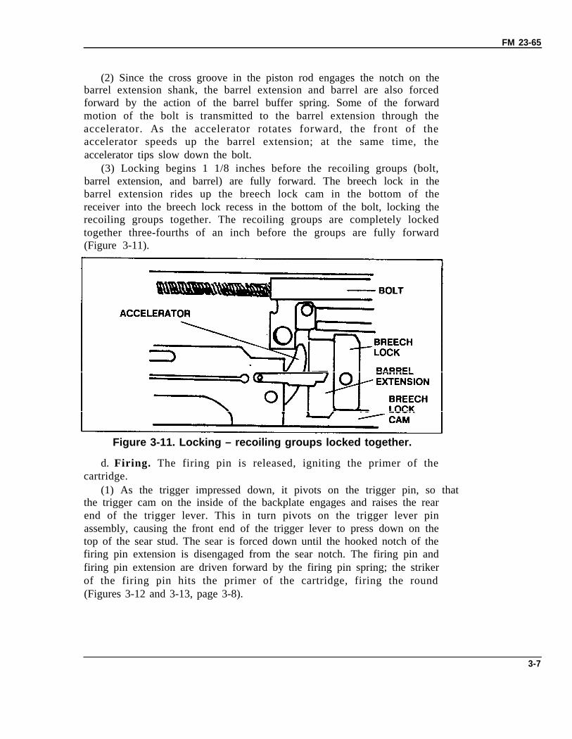
(2) Since the cross groove in the piston rod engages the notch on thebarrel extension shank, the barrel extension and barrel are also forcedforward by the action of the barrel buffer spring. Some of the forwardmotion of the bolt is transmitted to the barrel extension through theaccelerator. As the accelerator rotates forward, the front of theaccelerator speeds up the barrel extension; at the same time, theaccelerator tips slow down the bolt.
(3) Locking begins 1 1/8 inches before the recoiling groups (bolt,barrel extension, and barrel) are fully forward. The breech lock in thebarrel extension rides up the breech lock cam in the bottom of thereceiver into the breech lock recess in the bottom of the bolt, locking therecoiling groups together. The recoiling groups are completely lockedtogether three-fourths of an inch before the groups are fully forward(Figure 3-11).
Figure 3-11. Locking – recoiling groups locked together.
d. Firing. The firing pin is released, igniting the primer of thecartridge.
(1) As the trigger impressed down, it pivots on the trigger pin, so thatthe trigger cam on the inside of the backplate engages and raises the rearend of the trigger lever. This in turn pivots on the trigger lever pinassembly, causing the front end of the trigger lever to press down on thetop of the sear stud. The sear is forced down until the hooked notch of thefiring pin extension is disengaged from the sear notch. The firing pin andfiring pin extension are driven forward by the firing pin spring; the strikerof the firing pin hits the primer of the cartridge, firing the round(Figures 3-12 and 3-13, page 3-8).
3-7

FM 23-65
Figure 3-12. Firing – ready to fire.
Figure 3-13. Firing – round ignited.
(2) For automatic firing, the bolt-latch release must be locked or helddepressed, so that the bolt latch will not engage the notches in top of thebolt, holding the bolt to the rear as in single-shot firing. The trigger ispressed and held down. Each time the bolt travels forward incounter-recoil, the trigger lever depresses the sear, releasing the firing pinextension assembly and the firing pin. This automatically fires the nextround when the forward movement of the recoiling groups is nearlycompleted. The gun should fire about one-sixteenth of an inch before therecoiling groups are fully forward. Only the first round should be firedwith the parts fully forward. The gun fires automatically as long as thetrigger and bolt latch are held down and ammunition is fed into the gun.
e. Unlocking. The bolt is unlocked from the barrel and barrelextension.
(1) At the instant of firing, the bolt is locked to the barrel extensionand against the rear end of the barrel by the breech lock, which is on top
3-8

FM 23-65
of the breech lock cam and in the breech lock recess in the bottom of thebolt. When the cartridge explodes, the bullet travels out of the barrel; theforce of recoil drives the recoiling groups rearward. During the firstthree-fourths of an inch, the recoiling groups are locked together. As thismovement takes place, the breech lock is moved off the breech lock camstop, allowing the breech lock depressors (acting on the breech lock pin)to force the breech lock down, out of its recess from the bottom of thebolt. At the end of the first three-fourths of an inch of recoil, the bolt isunlocked, free to move to the rear independent of the barrel and barrelextension.
(2) As the recoiling groups move to the rear, the barrel extensioncauses the tips of the accelerator to rotate rearward. The accelerator tipsstrike the lower rear projection of the bolt, accelerating the movement ofthe bolt to the rear. The barrel and barrel extension continue to travel tothe rear an additional three-eighths of an inch, or an approximate totaldistance of 1 1/8 inches until they are stopped by the barrel bufferassembly (Figure 3-14).
Figure 3-14. Unlocking – barrel and barrel extension stopped bythe barrel buffer assembly.
(3) During the recoil of 1 1/8 inches, the barrel buffer spring iscompressed by the barrel extension shank, since the notch on the shank isengaged in the cross groove in the piston rod head. The spring is locked inthe compressed position by the claws of the accelerator, which engage theshoulders of the barrel extension shank. After its initial travel ofthree-fourths of an inch, the bolt travels an additional 6 3/8 inches to therear, after it is unlocked from the barrel and barrel extension, for a total of
3-9

FM 23-65
7 1/8 inches. During this movement, the driving springs are compressed.The rearward movement of the bolt is stopped as the bolt strikes thebuffer plate. Part of the recoil energy of the bolt is stored by the drivingspring rod assembly, and part is absorbed by the buffer disks in thebackplate (Figure 3-15).
Figure 3-15. Unlocking – recoil movement completed.
f. Extracting. The empty cartridge case is pulled from the chamber.(1) The empty case, held by the T-slot, has been expanded by the
force of the explosion; therefore, it fits snugly in the chamber. If the case iswithdrawn from the chamber too rapidly, it may be torn. To prevent this,and to ensure slow initial extraction of the case, the top forward edge ofthe breech lock and the forward edge of the lock recess in the bolt arebeveled. As the breech lock is unlocked, the initial movement of the boltaway from the barrel and barrel extension is gradual.
(2) The slope of the locking faces facilitates locking and unlocking andprevents sticking. The leverage of the accelerator tips on the bolt speedsextraction after it is started by kicking the bolt to the rear to extract theempty case from the chamber.
g. Ejecting. The empty cartridge case is expelled from the receiver.(1) As the bolt starts its forward movement (counter-recoil), the
extractor lug rides below the extractor switch, forcing the extractorassembly farther down until the round is in the center of the T-slot of thebolt.
(2) The round, still gripped by the extractor, ejects the empty casefrom the T-slot. The last empty case of an ammunition belt is pushed outby the ejector.
3-10

FM 23-65
h. Cocking. The firing pin is withdrawn into the cocked position.(1) When the recoiling groups are fully forward, the top of the cocking
lever rests on the rear half of the V-slot in the top plate bracket. As thebolt moves to the rear, the top of the cocking lever is forced forward. Thelower end pivots to the rear on the cocking lever pin. The rounded nose ofthe cocking lever, which fits through the slot in the firing pin extension,forces the extension to the rear, compressing the firing pin spring againstthe sear stop pin (accelerator stop). As the firing pin extension is pressedto the rear, the hooked notch of the extension rides over the sear notch,forcing the sear down. The sear spring forces the sear back up after thehooked notch of the firing pin extension has entered the sear notch.
(2) The pressure of the sear and firing pin springs holds the twonotches locked together. There is a slight overtravel of the firing pinextension in its movement to the rear to ensure proper engagement withthe sear. As the bolt starts forward, the overtravel is taken up andcompleted when the cocking lever enters the V-slot of the top platebracket, and is caromed toward the rear; pressure on the cocking lever isrelieved as the bolt starts forward.
3-5. LEFT-HAND FEEDBy repositioning some of the components, the MG is capable of alternatefeed. Ammunition can be fed into the weapon from the right or left side ofthe receiver; however the Army uses only left-hand feed. (See Table 3-1).
Table 3-1. Position of parts for left-hand feed.
3-11

FM 23-65
3-6. HEADSPACE AND TIMINGHeadspace is the distance between the face of the bolt and the base of thecartridge case, fully seated in the chamber. Timing is the adjustment of thegun so that firing takes place when the recoiling parts are in the correctposition for firing. Because the cartridge is held by the T-slot of the bolt,headspace with the MG is measured as the distance between the rear ofthe barrel and the face of the bolt. This occurs when the recoiling parts areforward and there is positive contact between the breech lock recess in thebolt and the lock in the barrel extensions. Periodic calibration checksshould be made of the gauge by direct support personnel at least annually.
WARNINGFiring a weapon that has improperly set headspace and timing could result indamage to the machine gun, or injury to the gunner. Damage may also occurin the trunnion block, base of the barrel, or face of the bolt. This warningapplies whether the gun is firing service ammunition or M1E1 blanks. (Theweapon has improper early timing when two rounds are fired – and firingstops.)
a. Gauges. The headspace and timing gauge consists of a headspacegauge and two timing gauges (Figure 3-16). These gauges provide anaccurate means of checking the adjustment of headspace and timing.
NOTE: The headspace and timing gauge should be keptwith the gun at all times.
Figure 3-16. Headspace and timing gauge.
b. Headspace. Check and set headspace before firing, after assemblingthe gun, and after replacing the barrel or receiver group. Use thefollowing procedures to set headspace.
(1) Raise the cover all the way up. Grasp the retracting slide handle(Figure 3-17). Using the retracting slide handle, retract the bolt until thebarrel-locking-spring lug is centered in the 3/8-inch hole on the right sideof the receiver (Figure 3-18).
3-12

FM 23-65
Figure 3-17. Raising the cover.
Figure 3-18. Retracting the bolt.
(2) Hold the bolt in this position and screw the barrel fully into thebarrel extension (Figure 3-19).
Figure 3-19. Screwing in the barrel.
3-13

FM 23-65
WARNINGWhen resetting the headspace and timing of a gun thathas been fired, use an asbestos mitt to avoid burns.
(3) With the bolt still retracted, unscrew the barrel two notches(clicks). Release the retracting slide handle and allow the bolt to goforward.
NOTE: At this point, check the barrel for rotation. Attempt toturn the barrel in either direction. The barrel should not turn.If the barrel does turn, stop here and check barrel notchesand the barrel-locking spring for damage.
(4) Pull the bolt to the rear with the retracting slide handle and hold.This cocks the weapon. Otherwise, the headspace gauge will not fit.
(5) Holding the retracting slide handle, release the bolt, and slowlyreturn the bolt fully forward (Figure 3-20). Do not press the trigger or letthe bolt slam forward.
Figure 3-20. Releasing the bolt.
3-14

FM 23-65
(6) Retract the retracting slide handle and separate the barrelextension from the trunnion block by a 1/16-inch gap (Figure 3-21).
Figure 3-21. Setting the gap.
(7) Raise the extractor out of the way to clear the top of the T-slot andtry both ends of the go/no-go gauge as shown in Figure 3-22.
NOTE: Insert the go end of the gauge between the face of the bolt andthe end of the barrel all the way up to the ring.
Figure 3-22. Using the gauge.
3-15

FM 23-65
(8) If the go end of the gauge enters the T-slot freely to the center ringof the gauge, and the no-go end will not enter, headspace is correct.Remove gauge. Headspace setting is now complete. If the go end of thegauge will not enter the T-slot freely, headspace is too tight. Continue asfollows.
(9) Retract the bolt so you can see the barrel-locking lug in the centerof the 3/8th-inch alignment hole on the right side of the receiver.
(10) Unscrew the barrel one notch (click).
(11) Return the bolt fully forward.
(12) Recheck headspace (step 9).
(13) Repeat steps 10 through 13 until the go gauge fits but the no-gogauge does not fit.
NOTE: You should not have to unscrew the barrel more than fivenotches (clicks) beyond the first setting of two clicks. If thiscondition does occur, turn in the machine gun to your unitarmorer for inspection.
(14) If the no-go end of the gauge enters the T-slot, headspace is tooloose. Adjust it using the same procedures as above, screwing the barrelinto the barrel extension rather than out.
(15) Repeat steps 10 through 13, one click at a time, until the no-gogauge does not fit but the go gauge does fit.
c. Timing. Timing is the adjustment of the weapon so that firing takesplace when the recoiling parts are between .020 and .116 inch out ofbattery to prevent contact between the front end of the barrel extensionand the trunnion block. Use the following procedures to set timing.
WARNINGMake sure the gun is clear of ammunition before starting.
(1) Check headspace first as previously described.
(2) Pull the bolt to the rear with the retracting slide handle and thenease bolt fully forward to cock the machine gun.
(3) Grasp the retracting slide handle and retract the bolt just enough(1/16 inch) to insert the no-fire gauge between the barrel extension andthe trunnion block. Release the retracting slide handle (Figure 3-23).
(4) Depress the trigger. Gun should not fire.
3-16

FM 23-65
NOTE:
NOTE:
Figure 3-23. Inserting the no-fire gauge.
Insert timing gauge with bevel against barrel notches.
If the gun does not fire, go to step 5. If the gun does fire, you haveearly timing. Go on to steps 7 through 14.
(5) Grasp the retracting slide handle and retract the bolt just enoughto remove the no-fire gauge and insert the fire gauge in the same place(Figure 3-24). Release the retracting slide handle.
Figure 3-24. Inserting the fire gauge.
(6) Depress the trigger. Gun should fire. If it does, timing adjustmentis now complete.
NOTE: If the gun does not fire, you have late timing. Go to steps7 through 14.
(7) Remove the gauge, cock the gun, and return the bolt forward(8) Insert the fire gauge.
3-17
FM 23-65
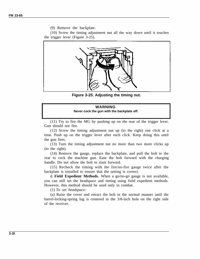
(9) Remove the backplate.(10) Screw the timing adjustment nut all the way down until it touches
the trigger lever (Figure 3-25).
Figure 3-25. Adjusting the timing nut.
WARNINGNever cock the gun with the backplate off.
(11) Try to fire the MG by pushing up on the rear of the trigger lever.Gun should not fire.
(12) Screw the timing adjustment nut up (to the right) one click at atime. Push up on the trigger lever after each click. Keep doing this untilthe gun fires.
(13) Turn the timing adjustment nut no more than two more clicks up(to the right).
(14) Remove the gauge, replace the backplate, and pull the bolt to therear to cock the machine gun. Ease the bolt forward with the charginghandle. Do not allow the bolt to slam forward.
(15) Recheck the timing with the fire/no-fire gauge twice after thebackplate is installed to ensure that the setting is correct.
d. Field Expedient Methods. When a go/no-go gauge is not available,you can still set the headspace and timing using field expedient methods.However, this method should be used only in combat.
(1) To set headspace:(a) Raise the cover and retract the bolt in the normal manner until the
barrel-locking-spring lug is centered in the 3/8-inch hole on the right sideof the receiver.
3-18

FM 23-65
(b) Hold the bolt in this position and screw the barrel fully into thebarrel extension; then unscrew the barrel two clicks or notches.
(2)(a)(b)(c)(3)( )a
To set timing:Use a dog tag or a dime as a fire gauge.Use a nickel and a dime or four dog tags as a no-fire gauge.Set the timing using the normal procedure.To check for correct settings:Attempt to fire the weapon. If it fires sluggishly, clear the weapon
then unscrew the barrel one more notch.(b) Recheck the rate of fire. Repeat the procedures in paragraph
however, do not exceed two more clicks.(c) Do not unscrew the barrel more than one notch between
firings.
(1);
test
3-19