operation and installation - stiebel eltron · the condensate drain may be blocked. clean the...
TRANSCRIPT

OPERATION AND INSTALLATION
Air | water heat pump
» WPL 34 » WPL 47 » WPL 57

2 | WPL 34 | WPL 47 | WPL 57 www.stiebel-eltron.com
CONTENTS
SPECIAL INFORMATION
OPERATION
1. General information �����������������������������������������41.1 Safety instructions ����������������������������������������������� 41.2 Other symbols in this documentation ����������������������� 41.3 Units of measurement ������������������������������������������ 41.4 Standardised output data �������������������������������������� 4
2. Safety ����������������������������������������������������������52.1 Intended use ������������������������������������������������������ 5
3. Appliance description ���������������������������������������53.1 Properties ��������������������������������������������������������� 53.2 Function ����������������������������������������������������������� 53.3 Equipment features ��������������������������������������������� 5
4. Operation �����������������������������������������������������5
5. Maintenance and care ���������������������������������������6
6. Troubleshooting ����������������������������������������������6
INSTALLATION
7. Safety ����������������������������������������������������������77.1 General safety instructions ������������������������������������ 77.2 Instructions, standards and regulations �������������������� 7
8. Appliance description ���������������������������������������78.1 Standard delivery ������������������������������������������������ 78.2 Required accessories ������������������������������������������� 78.3 Further accessories���������������������������������������������� 78.4 System configuration ������������������������������������������� 7
9. Preparations ��������������������������������������������������79.1 Sound emissions ������������������������������������������������� 79.2 Minimum clearances �������������������������������������������� 89.3 Substrate ���������������������������������������������������������� 89.4 Heat pump manager WPM ������������������������������������� 99.5 Buffer cylinder ��������������������������������������������������� 99.6 Electrical installation�������������������������������������������� 9
10. Installation �������������������������������������������������� 1010.1 Transport ��������������������������������������������������������� 1010.2 Siting �������������������������������������������������������������� 1010.3 Heating water connection ������������������������������������� 1010.4 Oxygen diffusion ������������������������������������������������ 1010.5 Filling the heating system ������������������������������������ 1010.6 Minimum flow rate ��������������������������������������������� 1010.7 Condensate drain ����������������������������������������������� 1110.8 Second heat source��������������������������������������������� 1110.9 Safety temperature controller for underfloor heating
system STB-FB �������������������������������������������������� 11
11. Power supply ����������������������������������������������� 1111.1 General ����������������������������������������������������������� 1111.2 Wiring chamber ������������������������������������������������� 1111.3 Electrical connections ������������������������������������������ 12
12. Fitting casing components �������������������������������� 12
13. Commissioning ��������������������������������������������� 1413.1 Checks before commissioning�������������������������������� 1413.2 Initial start-up ��������������������������������������������������� 1413.3 Shutdown �������������������������������������������������������� 15
14. Troubleshooting �������������������������������������������� 1514.1 Controls on the IWS �������������������������������������������� 1514.2 Fan noise ��������������������������������������������������������� 16
15. Maintenance ������������������������������������������������ 16
16. Specification ������������������������������������������������ 1716.1 Dimensions and connections ��������������������������������� 1716.2 Wiring diagram WPL 34 | WPL 47 ���������������������������� 1816.3 Wiring diagram WPL 57 ��������������������������������������� 2016.4 Output diagrams WPL 34 �������������������������������������� 2216.5 Output diagrams WPL 47 �������������������������������������� 2416.6 Output diagrams WPL 57 �������������������������������������� 2616.7 Data table �������������������������������������������������������� 28
GUARANTEE
ENVIRONMENT AND RECYCLING
SPECiaL iNfOrmaTiON
www.stiebel-eltron.com WPL 34 | WPL 47 | WPL 57 | 3
SPECiaL iNfOrmaTiON - The appliance may be used by children aged 8
and up and persons with reduced physical, sen-sory or mental capabilities or a lack of experience and know-how, provided that they are supervised or they have been instructed on how to use the appliance safely and have understood the result-ing risks. Children must never play with the ap-pliance. Children must never clean the appliance or perform user maintenance unless they are supervised.
- The connection to the power supply must be in the form of a permanent connection. Ensure the appliance can be separated from the power sup-ply by an isolator that disconnects all poles with at least 3 mm contact separation.
- Maintain the minimum clearances to ensure trou-ble-free operation of the appliance and facilitate maintenance work.
- In dual mode operation, return water from the second heat generator may flow through the heat pump. Please note that the return water tempera-ture may be a maximum of 60 °C.
- Maintenance work, such as checking the electri-cal safety, must only be carried out by a qualified contractor.
- We recommend an annual inspection (to establish the system's current condition), and maintenance by a qualified contractor if required (to return the system to the desired condition).
- Keep the air discharge and inlet apertures free from snow and leaves.
- Check regularly whether water collects beneath the appliance.
- Once per year, the refrigerant circuit must be test-ed for leaks in accordance with the EC Directive 517/2014. The tightness test must be documented in the log.
- Never interrupt the power supply, even outside the heating season. The system's active frost pro-tection is not guaranteed if the power supply is interrupted.
- There is no need to shut the system down in summer. The heat pump manager has an auto-matic summer / winter changeover.

OPEraTiON General information
4 | WPL 34 | WPL 47 | WPL 57 www.stiebel-eltron.com
OPEraTiON
1. General informationThe chapters "Special Information" and "Operation" are intended for both the user and qualified contractors.
The chapter "Installation" is intended for qualified contractors.
NoteRead these instructions carefully before using the appli-ance and retain them for future reference.Pass on the instructions to a new user if required.
1.1 Safety instructions
1.1.1 Structure of safety instructions
! KEYWORD Type of riskHere, possible consequences are listed that may result from failure to observe the safety instructions.ff Steps to prevent the risk are listed.
1.1.2 Symbols, type of risk
Symbol Type of risk
Injury
Electrocution
Burns(burns, scalding)
1.1.3 Keywords
KEYWOrD meaningDANGER Failure to observe this information will result in serious
injury or death.WARNING Failure to observe this information may result in serious
injury or death.CAUTION Failure to observe this information may result in non-seri-
ous or minor injury.
1.2 Other symbols in this documentation
NoteGeneral information is identified by the adjacent symbol.ff Read these texts carefully.
Symbol meaning
Material losses(appliance damage, consequential losses and environmen-tal pollution)
Appliance disposal
ff This symbol indicates that you have to do something. The ac-tion you need to take is described step by step.
1.3 Units of measurement
NoteAll measurements are given in mm unless stated oth-erwise.
1.4 Standardised output dataExplanations to determine and interpret the specified standardised output data
1.4.1 Standard: EN 14511
The output data specifically mentioned in text, diagrams and technical datasheets has been determined in line with the test conditions described in the standard shown in the heading of this chapter.
Generally, these standardised test conditions will not fully meet the conditions found at the installation site of the system user. Depending on the chosen test method and the extent to which the selected method deviates from the conditions described in the standard shown in the heading of this chapter, any deviations can have a considerable impact. Further factors that have an influence on the test values are the measuring equipment, the system con-figuration, the age of the system and the flow rates.
A confirmation of the specified output data can only be obtained if the conditions applicable to the relevant test match those of the standard shown in the heading of this chapter.
!
!

OPEraTiON Safety
www.stiebel-eltron.com WPL 34 | WPL 47 | WPL 57 | 5
2. Safety
2.1 Intended useThis appliance is intended for central heating and DHW heating in domestic applications. It can be used safely by untrained persons. The appliance can also be used in a non-domestic environment, e.g. in a small business, as long as it is used in the same way.
Any other use beyond that described shall be deemed inappropri-ate. Observation of these instructions and of instructions for any accessories used is also part of the correct use of this appliance.
Observe the application limits (see chapter "Specification / Data table").
Operate the appliance only when fully installed and with all safety equipment fitted.
Protect the appliance from dust and dirt ingress during building work.
! WARNING InjuryThe appliance may be used by children aged 8 and older and persons with reduced physical, sensory or mental capabilities or a lack of experience and know-how, pro-vided that they are supervised or they have been in-structed on how to use the appliance safely and have understood the resulting risks. Children must never play with the appliance. Children must never clean the ap-pliance or perform user maintenance unless they are supervised.
! WARNING Injuryff For safety reasons, only operate the appliance with the casing closed.
3. Appliance description
3.1 PropertiesThe appliance is an air|water heat pump that operates as a heat-ing heat pump. Heat is extracted from the outdoor air at a low temperature level, and is then transferred to the heating water at a higher temperature. The heating water can be heated up to a flow temperature of 60 °C.
Operational characteristics: - Suitable for underfloor and radiator heating. - Heat pump operates most efficiently on a low-temperature
heating system. - Still extracts heat from the outdoor air at - 20 °C outside
temperature.
NoteFor centralised control of the heating system, you would need the WPM heat pump manager.
NoteThe WPL 57 features a silent mode. Silent mode enables the heat pump noise emissions to be reduced. - Silent program 1 reduces the fan speed. - Silent program 2 switches the heat pump off.
Heating will [then] be provided by the internal or external second heat source. This results in higher electricity bills.ff Where required, set silent mode in the heat pump manager.
3.2 FunctionHeat is extracted from the outdoor air via the heat exchanger (evaporator) on the air side. The now evaporated refrigerant is compressed with a compressor. This process requires electrical energy. This electrical energy helps to heat the room.
At air temperatures below approx. + 7 °C, the humidity in the air condenses as hoarfrost on the evaporator fins. Any hoarfrost is au-tomatically defrosted. Water created from this defrosting process collects in the defrost pan and is drained off via a hose.
The heat pump automatically reverts to heating mode at the end of the defrost cycle.
! Material lossesIn dual mode operation, return water from the second heat generator may flow through the heat pump. Please note that the return water temperature may be a maxi-mum of 60 °C.
3.3 Equipment features - Corrosion-protected, external casing made from galvanised
sheet steel plus powder-coated finish. - Comprises all components and safety equipment required for
operation. - Filled with non-combustible safety refrigerant.
4. Operation Operation is exclusively controlled via the heat pump manager.ff Observe the heat pump manager operating and installation instructions.

OPEraTiON maintenance and care
6 | WPL 34 | WPL 47 | WPL 57 www.stiebel-eltron.com
5. Maintenance and care
! Material lossesMaintenance work, such as checking the electrical safety, must only be carried out by a heating contractor.
We recommend an annual inspection (to establish the system's current condition), and maintenance by a qualified contractor if required (to return the system to the desired condition).ff A damp cloth is sufficient for cleaning all plastic and sheet metal parts. Never use abrasive or corrosive cleaning agents.
NoteKeep the air discharge and intake apertures free from snow and leaves.
ff Check regularly whether water collects beneath the appliance.ff In the event of water collecting beneath the appliance, call a qualified contractor to have the condensate drain cleaned out.
NoteOnce per year, the refrigerant circuit must be tested for leaks in accordance with the EC Directive 517/2014.The tightness test must be documented in the log.
6. Troubleshootingfault Cause remedyThere is no hot water or the heat-ing system stays cold.
No power at the appliance.
Check the fuses/MCBs in your fuse box/distribu-tion panel. Replace the fuses/reset the MCBs if required. Notify your qualified contractor if the fuses/MCBs blow/trip again.
Water is leaking from the appli-ance.
The condensate drain may be blocked.
Clean the condensate drain as described in chapter 'Care and main-tenance'.
Condensate is collecting on the outside of the ap-pliance.
The heat pump is drawing heat from the outdoor air to heat the building. This can cause the humidity in the outdoor air to accumulate as dew or frost on the cooled heat pump casing. This is not a defect.
NoteEven when the condensate is draining away correctly, expect water to drip from the appliance onto the floor.
If you cannot remedy the fault, notify your qualified contractor. To facilitate and speed up your request, provide the number from the type plate (000000-0000-000000). The type plate is located at the front top, on the right or left hand side of the casing.
Example
Montageanweisung beachten! Dichtheit geprüft! Made in Germany
*xxxxxxxxxxxxxxxxxx*
26�0
3�01
�143
0
1
1 Number on the type plate

iNSTaLLaTiON Safety
www.stiebel-eltron.com WPL 34 | WPL 47 | WPL 57 | 7
iNSTaLLaTiON
7. SafetyOnly a qualified contractor should carry out installation, commis-sioning, maintenance and repair of the appliance.
7.1 General safety instructionsWe guarantee trouble-free function and operational reliability only if original accessories and spare parts intended for the appliance are used.
7.2 Instructions, standards and regulations
NoteObserve all applicable national and regional regulations and instructions.
8. Appliance descriptionFor outdoor installation the appliance offers additional frost pro-tection of the heating water pipes. The integral frost protection circuit starts the circulation pump in the heat pump circuit auto-matically at +8 °C condenser temperature, and thereby ensures circulation in all water-filled sections. The heat pump is started automatically no later than when the temperature inside the buffer cylinder drops below +5 °C.
8.1 Standard deliveryThe casing components for the appliance are delivered in a sep-arate pack.
8.1.1 Standard appliance - Logbook - Type plate - Condensate drain hose - Wiring diagram
8.1.2 Casing components - 2 Covers - 4 Air deflector hoods - 1 Front panel - 1 Back panel - 4 Side panels - 4 Plinth trim
8.2 Required accessoriesYou require the following accessories to operate the heat pump: - Heat pump manager WPM 3 - Remote control for heating systems FE7 - Buffer cylinder - Circulation pump UP 30/1-8 PCV
8.3 Further accessories - Internet Service Gateway ISG - Mixer module MSMW - Contact sensor - Immersion sensor
8.4 System configurationYou will find the accessory drawings and versions in the specific technical guides for your system.
9. Preparations
9.1 Sound emissionsThe appliance is louder on the air intake and air discharge sides than on the two enclosed sides. Observe the following information when selecting the installation location.
NoteFor details regarding the sound power level, see chapter "Specification / Data table".
- Lawn areas and shrubs help reduce the spread of noise. - Sound propagation can also be reduced by installing closely
spaced palisade fencing around the appliance. ff Ensure that the air intake direction is the same as the dom-inant wind direction. Air should not be drawn in against the wind.ff Never direct the air intake or discharge towards noise-sensi-tive rooms of the house, e.g. bedrooms.ff Avoid installation on large, echoing floor areas, e.g. tiled floors.ff Avoid installation between reflective building walls. Reflect-ing building walls can increase the noise level.

iNSTaLLaTiON Preparations
8 | WPL 34 | WPL 47 | WPL 57 www.stiebel-eltron.com
9.2 Minimum clearances
≥500 ≥1000≥500≥500
≥500
D00
0002
0332
ff Maintain the minimum clearances to ensure trouble-free op-eration of the appliance and facilitate maintenance work.
91�0
0�00
�003
6
ff Never install the appliance in a recess. Two sides of the ap-pliance must remain exposed.
! Material lossesPlease note that both the flow of outdoor air into the appliance, and the flow of exhaust air from the appliance must be unimpeded.If the air intake and discharge of the appliance are ob-structed by surrounding objects, this may cause a thermal short-circuit.
ff Ensure that the appliance is not fully enclosed by objects such as buildings, walls or fences. ff If necessary, maintain a greater clearance to the surrounding objects.
! Material lossesThe air flow rate through the appliance must not fall below the minimum level. If the air flow rate falls below the minimum level, trouble-free operation of the appli-ance is not guaranteed.
ff Ensure that the minimum air flow rate is maintained. Ob-serve the details in chapter "Specification / Data table".
! WARNING InjuryOn the air discharge side, discharged air can result in the formation of ice on footpaths and driveways in winter.
ff If necessary, maintain a greater clearance to the surrounding objects.
If the air discharge side of the appliance faces a wall of a house, the cool air from the air discharge may cause condensate to form on this wall.
NoteIf the air discharge side faces house walls, maintain a minimum clearance of 2 m between the appliance and the building.
9.3 Substrateff The substrate must be horizontal, level, solid and permanent.ff Observe chapter "Sound emissions".
NoteProvide a recess (space) in the substrate to enable water and electrical pipes/cables to be connected from below.
Example: Foundations with recess
4
1
2
32200360
173
255
1150
440
5 155
260
D00
0002
6155
1 Air discharge2 Air intake3 Main wind direction4 Supply line outlet5 Knock-out inside the appliance

iNSTaLLaTiON Preparations
www.stiebel-eltron.com WPL 34 | WPL 47 | WPL 57 | 9
A
5
8
1 2
7
6
43≥10
D00
0002
2105
A Depth of frost line1 Heating flow 2 Heating return3 Conduit for supply lines/cables4 Foundation5 Coarse gravel back filling6 Condensate drain pipe7 Condensate drain8 Electrical power cable
250
105
D00
0004
8227
1
2
1 Heating flow 2 Heating returnff Protect the flow and return pipes and the electrical cables against damage and moisture with an installation conduit. ff Protect the flow and return lines against frost with sufficient thermal insulation. The required insulation thickness is de-scribed in the Energy Savings Ordinance.ff Only use weather-resistant cables.
9.4 Heat pump manager WPMA WPM heat pump manager is required to operate the appliance. This controls the heat pump and regulates the heating system.
9.5 Buffer cylinderThe installation of a buffer cylinder is essential to ensure trou-ble-free operation of the appliance.
The buffer cylinder provides hydraulic separation of the volume flows in the heat pump circuit and heating circuit, and also serves as an energy source for defrosting.
9.6 Electrical installation
WARNING ElectrocutionCarry out all electrical connection and installation work in accordance with national and regional regulations.
WARNING ElectrocutionOnly use a permanent connection to the power supply. The appliance must be able to be separated from the power supply by an isolator that disconnects all poles with at least 3 mm contact separation. This requirement can be met with contactors, circuit breakers, fuses/MCBs, etc.
! Material lossesThe specified voltage must match the mains voltage. Ob-serve the type plate.
In accordance with VDE 0298-4, use the following line cross-sec-tions subject to their fuse protection:
mCB/fuse rating
assignment Cable cross-section
B 16 A Control 1.5 mm²C 32 A
Compressor
10.0 mm² when routing in a wall.6.0 mm² when routing a multi-core line on a wall or in an electrical conduit on a wall.
The electrical specifications are given in the "Data table". You require a J-Y (St) 2x2x0.8 mm² cable for the BUS.
NoteProvide separate fuses for the two power circuits of the appliance and the control unit.

iNSTaLLaTiON installation
10 | WPL 34 | WPL 47 | WPL 57 www.stiebel-eltron.com
10. Installation
10.1 Transportff Pay attention to the appliance's centre of gravity when trans-porting the appliance.
The centre of gravity is in the area where the compressor is lo-cated.ff Protect the appliance against heavy impact during transport.
Where space is restricted, you can also tilt the appliance at an angle to move it.
10.2 Sitingff Pay attention to the air discharge direction.ff Position the appliance on the prepared substrate. ff Level the appliance horizontally by adjusting the feet.ff Route the water pipes and electrical cables into the appliance from below through the knock-outs in the base.
NoteDo not fit the casing components until the electrical and hydraulic connections have been made.
10.3 Heating water connectionThe heating system to which the heat pump is connected must be installed by a qualified contractor in accordance with the water installation drawings that are part of the technical guides.ff Thoroughly flush the pipework before connecting the heat pump.
Debris, such as welding pearls, rust, sand, sealant, etc. can impair the operational reliability of the heat pump.
10.4 Oxygen diffusion
! Material lossesAvoid open heating systems and plastic pipes in under-floor heating systems which are permeable to oxygen.
In underfloor heating systems with plastic pipes that are per-meable to oxygen and in open vented heating systems, oxygen diffusion may lead to corrosion on the steel components of the heating system (e.g. on the indirect coil of the DHW cylinder, on buffer cylinders, steel heating elements or steel pipes).
! Material lossesThe products of corrosion (e.g. rusty sludge) can settle in the heating system components and can result in a lower output or fault shutdowns due to reduced cross-sections.
10.5 Filling the heating system
10.5.1 Heating water quality
Carry out a fill water analysis before the system is filled. This may, for example, be requested by the relevant water supply utility.
! Material lossesTo avoid damage as a result of scaling, it may be neces-sary to soften or desalinate the fill water. Always observe the fill water limits specified in the "Specification / Data table" chapter.ff Recheck these limits 8-12 weeks after commission-ing and as part of the annual system maintenance.
Note With a conductivity >1000 μS/cm, desalination treatment is recommended in order to avoid corrosion.
Note Suitable appliances for water softening and desalinating, as well as for charging and flushing heating systems, can be obtained via trade suppliers.
Note If you treat the fill water with inhibitors or additives, the same limits as for desalination apply.
10.5.2 Venting the heating systemff Vent the pipework carefully. For this, also activate the air vent valve integrated into the heating flow inside the heat pump.
10.6 Minimum flow rateThe minimum flow rate is set via the temperature differential of the buffer circuit.
Set the buffer charging pump so that the value is equal to or lower than the maximum temperature differential.
The setting is made in heat pump mode. For this, make the fol-lowing settings first:ff Temporarily remove the fuse from the electric emergency/booster heater to isolate the emergency/booster heater from the power supply. Alternatively, switch OFF the second heat generator.ff Operate the appliance in heating mode.
10.6.1 Flow rate with buffer cylinder
When using a buffer cylinder, make the following setting: In the menu "SETTINGS / HEATING / STANDARD SETTINGS", set param-eter "BUFFER OPERATION" to "ON".
The flow rate can be adjusted using the temperature differential of the buffer circuit. The value must not fall below the minimum flow rate.

iNSTaLLaTiON Power supply
www.stiebel-eltron.com WPL 34 | WPL 47 | WPL 57 | 11
Maximum temperature differential on the heating side with buffer cylinder:
1
0
2
4
6
8
10
-15 -10 -5 0 5 10 15 20 25 30 D
0000
0635
50
1 Nominal flow rateX Outside temperature [°C]Y Maximum temperature differential [K]ff Make the settings at the circulation pump when the temper-ature differential between the flow and return temperature has stabilised.ff Compare the resulting temperature differential between the flow and return at the appliance with the diagram “Maxi-mum temperature differential on the heating side with buffer cylinder”.ff Set the buffer charging pump so that the maximum tempera-ture differential is achieved or undershot.ff If the appliance will be used for DHW heating, check the set-ting of the delivery head in DHW mode. ff If necessary, adjust the delivery head setting for the DHW primary pump.ff Set the buffer charging pump and the DHW primary pump to ∆p constant.
10.7 Condensate drainA pipe for the condensate drain is fitted at the factory to the defrost pan. The pipe terminates near the aperture on the floor plate. The appliance is supplied with a two meter hose with elbow plug-in fittings for draining the condensate.ff Secure the hose supplied on the pipe of the defrost pan.
10.8 Second heat sourceFor dual mode systems, always connect the heat pump into the return of the second heat generator (e.g. oil boiler).
10.9 Safety temperature controller for underfloor heating system STB-FB
! Material lossesIn case of failure, in order to prevent an excessively high flow temperature in the underfloor heating system, we generally recommend the use of a safety temperature controller to limit the system temperature.
11. Power supply
11.1 General
WARNING ElectrocutionBefore working on the appliance, isolate it from the power supply at the control panel.
Please observe the heat pump manager operating and installation instructions.
Only qualified electricians must carry out the installation in ac-cordance with these instructions.
Permission to connect the appliance may need to be obtained from your local power supply utility.
11.2 Wiring chamberThe terminal box is located on the air outlet side.ff Open the junction box as shown:
26�0
3�01
�141
2
NoteThe wiring diagram of the appliance is located behind the cover.
Use appropriate cables in accordance with local regulations for all connections.ff Route the cables through the knock-out in the floor, through the cable trunking and upwards into the junction box.ff Route the electrical cables through the cable entries with strain reliefs.ff Check the function of the strain relief fittings.
iNSTaLLaTiON fitting casing components
12 | WPL 34 | WPL 47 | WPL 57 www.stiebel-eltron.com
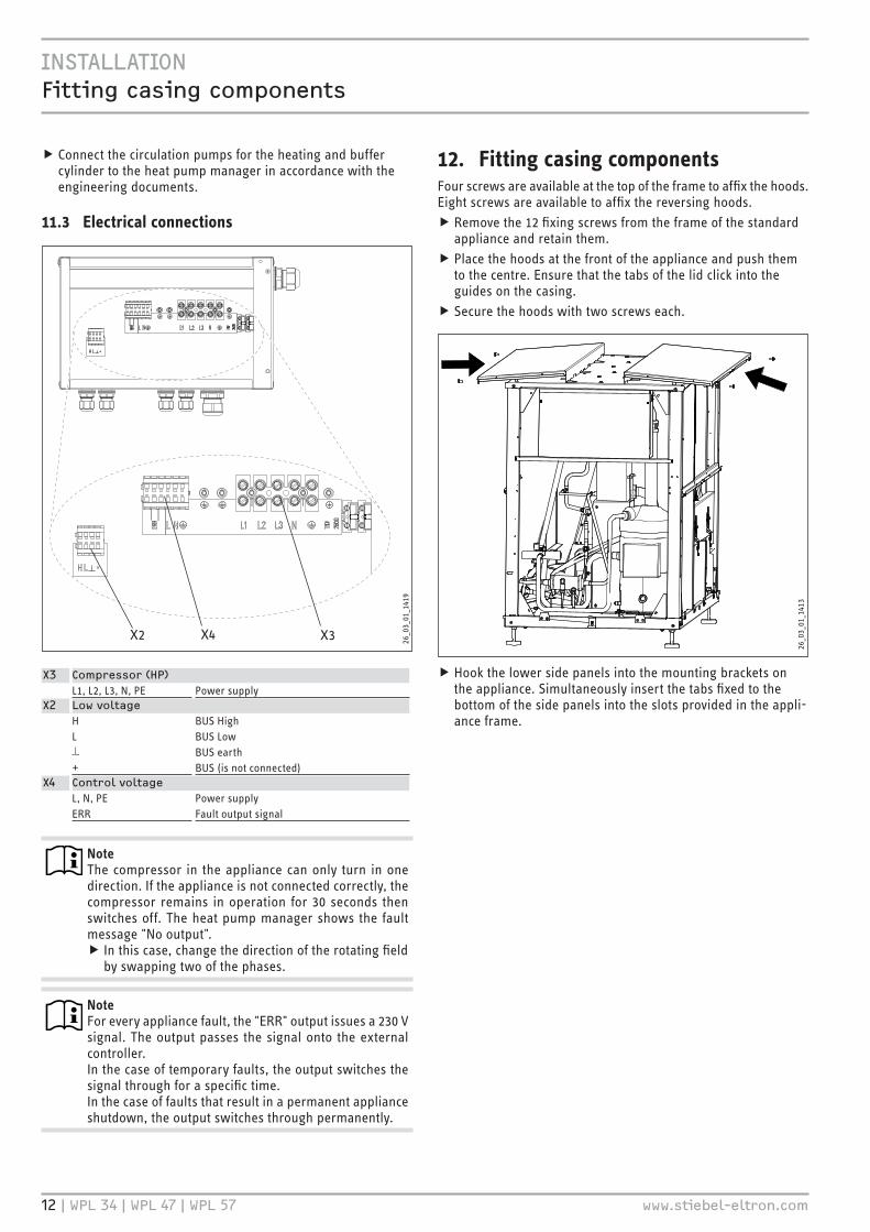
ff Connect the circulation pumps for the heating and buffer cylinder to the heat pump manager in accordance with the engineering documents.
11.3 Electrical connections
X2 X3X4 26�0
3�01
�141
9
X3 Compressor (HP)L1, L2, L3, N, PE Power supply
X2 Low voltageH BUS HighL BUS Low⊥ BUS earth+ BUS (is not connected)
X4 Control voltageL, N, PE Power supplyERR Fault output signal
NoteThe compressor in the appliance can only turn in one direction. If the appliance is not connected correctly, the compressor remains in operation for 30 seconds then switches off. The heat pump manager shows the fault message "No output". ff In this case, change the direction of the rotating field by swapping two of the phases.
Note For every appliance fault, the "ERR" output issues a 230 V signal. The output passes the signal onto the external controller.In the case of temporary faults, the output switches the signal through for a specific time.In the case of faults that result in a permanent appliance shutdown, the output switches through permanently.
12. Fitting casing componentsFour screws are available at the top of the frame to affix the hoods. Eight screws are available to affix the reversing hoods.ff Remove the 12 fixing screws from the frame of the standard appliance and retain them.ff Place the hoods at the front of the appliance and push them to the centre. Ensure that the tabs of the lid click into the guides on the casing.ff Secure the hoods with two screws each.
26�0
3�01
�141
3
ff Hook the lower side panels into the mounting brackets on the appliance. Simultaneously insert the tabs fixed to the bottom of the side panels into the slots provided in the appli-ance frame.

iNSTaLLaTiON fitting casing components
www.stiebel-eltron.com WPL 34 | WPL 47 | WPL 57 | 13
D00
0003
2213
ff Hook the reversing hoods into the mounting brackets at the top and bottom.
26�0
3�01
�141
5
ff Secure the reversing hoods with two screws each.
26�0
3�01
�142
1
ff Hook the front and back panels into the mounting brackets of the hoods. Simultaneously insert the tabs fixed to the bottom of the panels into the slots provided in the appliance frame.ff Secure the front and back panels using the mounting tabs provided for this purpose at the bottom of the appliance frame.
26�0
3�01
�141
6
ff Secure the side plinth trims by hooking into the appliance frame.ff Secure the front and back plinth trims by hooking into the side plinth trims.
iNSTaLLaTiON Commissioning
14 | WPL 34 | WPL 47 | WPL 57 www.stiebel-eltron.com
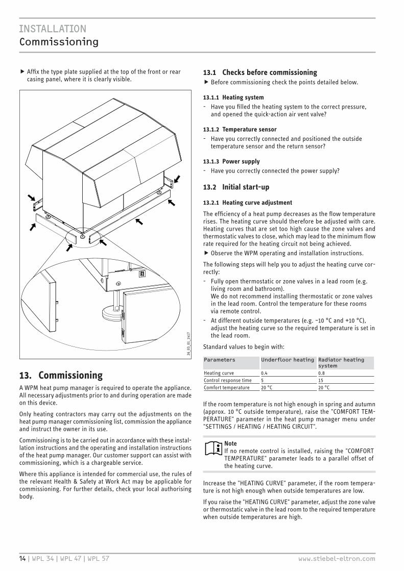
ff Affix the type plate supplied at the top of the front or rear casing panel, where it is clearly visible.
26�0
3�01
�141
7
13. CommissioningA WPM heat pump manager is required to operate the appliance. All necessary adjustments prior to and during operation are made on this device.
Only heating contractors may carry out the adjustments on the heat pump manager commissioning list, commission the appliance and instruct the owner in its use.
Commissioning is to be carried out in accordance with these instal-lation instructions and the operating and installation instructions of the heat pump manager. Our customer support can assist with commissioning, which is a chargeable service.
Where this appliance is intended for commercial use, the rules of the relevant Health & Safety at Work Act may be applicable for commissioning. For further details, check your local authorising body.
13.1 Checks before commissioningff Before commissioning check the points detailed below.
13.1.1 Heating system - Have you filled the heating system to the correct pressure,
and opened the quick-action air vent valve?
13.1.2 Temperature sensor - Have you correctly connected and positioned the outside
temperature sensor and the return sensor?
13.1.3 Power supply - Have you correctly connected the power supply?
13.2 Initial start-up
13.2.1 Heating curve adjustment
The efficiency of a heat pump decreases as the flow temperature rises. The heating curve should therefore be adjusted with care. Heating curves that are set too high cause the zone valves and thermostatic valves to close, which may lead to the minimum flow rate required for the heating circuit not being achieved.ff Observe the WPM operating and installation instructions.
The following steps will help you to adjust the heating curve cor-rectly: - Fully open thermostatic or zone valves in a lead room (e.g.
living room and bathroom). We do not recommend installing thermostatic or zone valves in the lead room. Control the temperature for these rooms via remote control.
- At different outside temperatures (e.g. –10 °C and +10 °C), adjust the heating curve so the required temperature is set in the lead room.
Standard values to begin with:
Parameters Underfloor heating radiator heating system
Heating curve 0.4 0.8Control response time 5 15Comfort temperature 20 °C 20 °C
If the room temperature is not high enough in spring and autumn (approx. 10 °C outside temperature), raise the "COMFORT TEM-PERATURE" parameter in the heat pump manager menu under "SETTINGS / HEATING / HEATING CIRCUIT".
NoteIf no remote control is installed, raising the "COMFORT TEMPERATURE" parameter leads to a parallel offset of the heating curve.
Increase the "HEATING CURVE" parameter, if the room tempera-ture is not high enough when outside temperatures are low.
If you raise the "HEATING CURVE" parameter, adjust the zone valve or thermostatic valve in the lead room to the required temperature when outside temperatures are high.
iNSTaLLaTiON Troubleshooting
www.stiebel-eltron.com WPL 34 | WPL 47 | WPL 57 | 15
NoteNever reduce the temperature in the entire building by closing all zone or thermostatic valves, instead use the setback programs.
When everything has been implemented correctly, the system can be heated to its maximum operating temperature and vented once again.
! Material lossesWith underfloor heating systems, observe the maximum permissible temperature for the system.
13.2.2 Other settingsff For operation with and without buffer cylinder, observe chapter "Operation / Menu structure / Menu SETTINGS / STANDARD SETTING / BUFFER OPERATION" in the operating and installation instructions of the WPM.
When using the heat-up program
If you use the heat-up program, make the following settings on the WPM:ff Initially set parameter "DUAL MODE TEMP HZG" to 30 °C.ff Then set parameter "LOWER APP LIMIT HZG" to 30 °C.
NoteAfter completing the heat-up process, reset the parame-ters "DUAL MODE TEMP HZG" and "LOWER APP LIMIT HZG" to their respective standard values or to the respective system values.
13.3 Shutdown
! Material lossesNever interrupt the heat pump power supply, even out-side the heating season. Otherwise, system frost protec-tion is not guaranteed. The heat pump manager automatically switches the heat pump to summer or winter mode.
13.3.1 Standby mode
If the appliance is to be taken out of use, set the WPM to standby. This retains the safety functions designed to protect the system (e.g. frost protection).
13.3.2 Power interruption
If the system is permanently isolated from the power supply, please observe the following:
! Material lossesIf the heat pump and frost protection are completely switched off, drain the system on the water side.
14. Troubleshooting
NotePlease observe the heat pump manager operating and installation instructions.
NoteThe following inspection instructions may only be carried out by a qualified contractor.
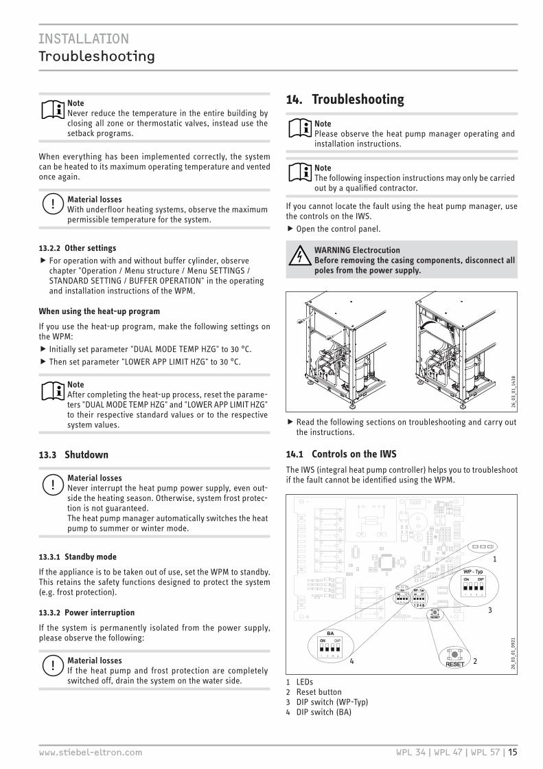
If you cannot locate the fault using the heat pump manager, use the controls on the IWS.ff Open the control panel.
WARNING ElectrocutionBefore removing the casing components, disconnect all poles from the power supply.
26�0
3�01
�143
8
ff Read the following sections on troubleshooting and carry out the instructions.
14.1 Controls on the IWSThe IWS (integral heat pump controller) helps you to troubleshoot if the fault cannot be identified using the WPM.
2
1
BA
BA
26�0
3�01
�092
1
4
3
1 LEDs2 Reset button3 DIP switch (WP-Typ)4 DIP switch (BA)

iNSTaLLaTiON maintenance
16 | WPL 34 | WPL 47 | WPL 57 www.stiebel-eltron.com
14.1.1 Checking the "HP type" DIP switch on the IWSff Check whether the "WP-Typ" DIP switch is set as follows:
WP - TypON
1 2 3 4 D00
0005
7055
14.1.2 Checking the IWS DIP switch "BA"ff Check whether the "BA" DIP switch is set as follows:
BAON
1 2 3 4 D00
0005
7050
14.1.3 LED
Red LEDfault Cause remedyThe appliance shuts down for 12 minutes and then restarts. Red LED flashes.
Heat pump fault.
Check the fault message in the WPM. Find the solution in the WPM in-structions (fault list). Per-form a reset of the IWS (see WPM instructions).
Appliance stops perma-nently. Red LED illumi-nates.
Five faults within two hours.
Check the fault message in the WPM. Find the solution in the WPM in-structions (fault list). Per-form a reset of the IWS (see WPM instructions).
Green LED centre
The LED flashes during initialisation, and illuminates constantly after the BUS address has been assigned successfully. Only then has communication with the WPM been established.
14.1.4 Reset button
If the IWS was incorrectly initialised, the settings can be reset with this button. For this also observe the chapter "Reinitialising IWS" in the heat pump manager operating and installation instructions.
14.2 Fan noiseThe heat pump draws heat from the outdoor air. This causes the outdoor air to cool down. At outside temperatures of 0 °C to 8 °C, the air may be cooled to below freezing point. If under these conditions precipitation occurs in the form of rain or fog, ice may form on the air grille, the fan blades or the airways. If the fan comes into contact with this ice, noise develops.
How to remedy rhythmic scratching or grinding noises:ff Check whether the condensate drain is clear of obstructions.ff Carry out a manual defrost, repeatedly if required, until the fan runs free again.ff At outside temperatures above + 1 °C, switch the appliance off for around 1 hour or switch it over to emergency mode. After this, the ice should have melted.ff Check whether the appliance is installed in line with the in-stallation conditions.ff If the noises occur frequently, notify customer support.
15. Maintenance
WARNING ElectrocutionPrior to maintenance and cleaning work, isolate the ap-pliance from its power supply.
We recommend that you perform an annual inspection (to estab-lish the current condition of the system), and carry out any main-tenance as required (to return the system to its original condition).
Cleaning the condensate drain
Environmental conditions may result in the condensate drain be-coming blocked. To clean the drain, proceed as follows:
Remove casing panels (see chapter "Installation").ff Check the hose and the pipe of the condensate drain. ff Remove dirt and blockages immediately.ff Refit the casing parts on the appliance (see chapter "Installation").

iNSTaLLaTiON Specification
www.stiebel-eltron.com WPL 34 | WPL 47 | WPL 57 | 17
16. Specification
16.1 Dimensions and connections
g01 g02
i21 i21
D00
0001
6788
g01 Air intakeg02 Air dischargei21 Entry supply line
iNSTaLLaTiON Specification
18 | WPL 34 | WPL 47 | WPL 57 www.stiebel-eltron.com
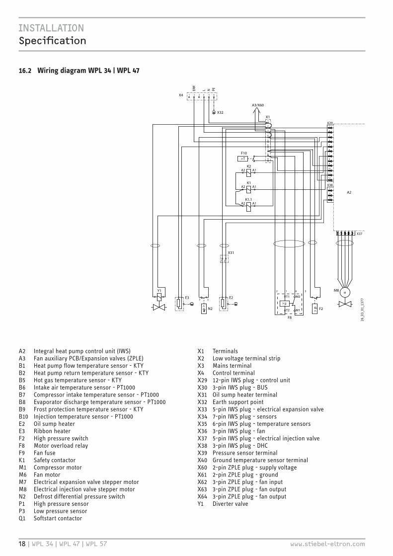
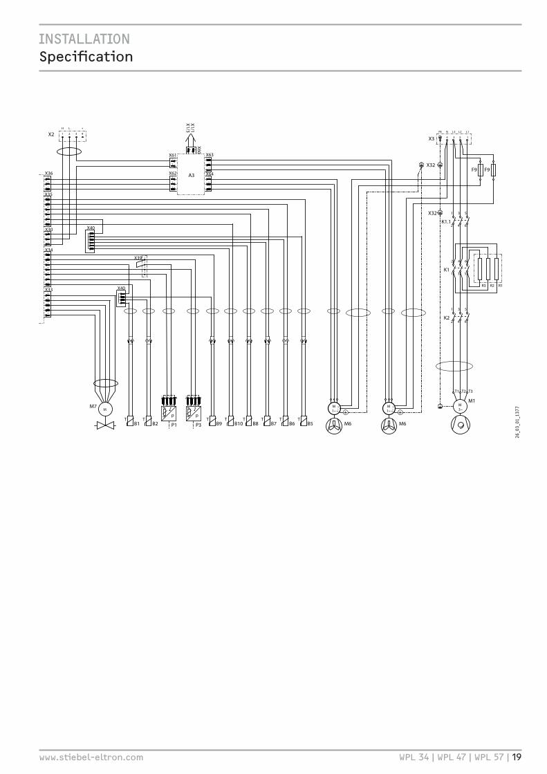
16.2 Wiring diagram WPL 34 | WPL 47
1
2
3
4
X1
A2
X29 X36
X35
X30
X34
X33
Y1
p >
32
N2 F2
F8>
p
X31
E2E3
1
2 1 4 3
2
B5T
B6T
B7T
B8T
B2T
X4 X2 1 2 3 4 5 6
ERR
L N PE
M6
M1~
A2 A1K1.1
1
2
3
4
5
6
7
8
9
1
2
3
4
5
6
7
8
9
10
11
12
1
2
3
H L � +
1 2 3 4
X38
3
2
1
X623
2
1
6
5
4
3
2
1
3
2
1
7
6
5
4
3
2
1
5
4
3
2
1
3 2 1
p
P3
3 2 1
p
P1 B10T
B9T
B1T
N LPE
M6
M1~
N LPE
PE N L3 L2 L1
4 3 2 1
M1M3~
531
2 4 6K1.1
642
1 3 5K1
531
2 4 6K2
T1 T2 T3
X3
X32
X3754321
M8M
X40
X40
X39 A2 A1
K1
A2 A1K2
T1
T2
> u
M2
M1
X611
2
X633
2
1
X643
2
1
A3F9 F9
A3/X60
X6012
X1/1
X1/3
X32X32
R2R3 R1
>T
F10
M7M
26�0
3�01
�137
7
A2 Integral heat pump control unit (IWS)A3 Fan auxiliary PCB/Expansion valves (ZPLE)B1 Heat pump flow temperature sensor - KTYB2 Heat pump return temperature sensor - KTYB5 Hot gas temperature sensor - KTYB6 Intake air temperature sensor - PT1000B7 Compressor intake temperature sensor - PT1000B8 Evaporator discharge temperature sensor - PT1000B9 Frost protection temperature sensor - KTYB10 Injection temperature sensor - PT1000E2 Oil sump heaterE3 Ribbon heaterF2 High pressure switchF8 Motor overload relayF9 Fan fuseK1 Safety contactorM1 Compressor motorM6 Fan motorM7 Electrical expansion valve stepper motorM8 Electrical injection valve stepper motorN2 Defrost differential pressure switchP1 High pressure sensorP3 Low pressure sensorQ1 Softstart contactor
X1 TerminalsX2 Low voltage terminal stripX3 Mains terminalX4 Control terminalX29 12-pin IWS plug - control unitX30 3-pin IWS plug - BUSX31 Oil sump heater terminalX32 Earth support pointX33 5-pin IWS plug - electrical expansion valveX34 7-pin IWS plug - sensorsX35 6-pin IWS plug - temperature sensorsX36 3-pin IWS plug - fanX37 5-pin IWS plug - electrical injection valveX38 3-pin IWS plug - DHCX39 Pressure sensor terminalX40 Ground temperature sensor terminalX60 2-pin ZPLE plug - supply voltageX61 2-pin ZPLE plug - groundX62 3-pin ZPLE plug - fan inputX63 3-pin ZPLE plug - fan outputX64 3-pin ZPLE plug - fan outputY1 Diverter valve
iNSTaLLaTiON Specification
www.stiebel-eltron.com WPL 34 | WPL 47 | WPL 57 | 19
1
2
3
4
X1
A2
X29 X36
X35
X30
X34
X33
Y1
p >
32
N2 F2
F8
> p
X31
E2E3
1
2 1 4 3
2
B5T
B6T
B7T
B8T
B2T
X4 X2 1 2 3 4 5 6
ERR
L N PE
M6
M1~
A2 A1K1.1
1
2
3
4
5
6
7
8
9
1
2
3
4
5
6
7
8
9
10
11
12
1
2
3
H L � +
1 2 3 4
X38
3
2
1
X623
2
1
6
5
4
3
2
1
3
2
1
7
6
5
4
3
2
1
5
4
3
2
1
3 2 1
p
P3
3 2 1
p
P1 B10T
B9T
B1T
N LPE
M6
M1~
N LPE
PE N L3 L2 L1
4 3 2 1
M1M3~
531
2 4 6K1.1
642
1 3 5K1
531
2 4 6K2
T1 T2 T3
X3
X32
X3754321
M8M
X40
X40
X39 A2 A1
K1
A2 A1K2
T1
T2
> u
M2
M1
X611
2
X633
2
1
X643
2
1
A3F9 F9
A3/X60
X6012
X1/1
X1/3
X32X32
R2R3 R1
>T
F10
M7M
26�0
3�01
�137
7

iNSTaLLaTiON Specification
20 | WPL 34 | WPL 47 | WPL 57 www.stiebel-eltron.com
16.3 Wiring diagram WPL 57
1
2
3
4A2
X29 X36
X35
X30
X34
X33
B5T
B6T
B7T
B8T
B2T
X2
M6
M1~
1
2
3
4
5
6
7
8
9
10
11
12
1
2
3
H L � +
1 2 3 4
X38
3
2
1
X623
2
1
6
5
4
3
2
1
3
2
1
7
6
5
4
3
2
1
5
4
3
2
1
3 2 1
p
P3
3 2 1
p
P1 B10T
B9T
B1T
N LPE
M6
M1~
N LPE
PE N L3 L2 L1
4 3 2 1
M1M3~
531
2 4 6K1.1
642
1 3 5K1
531
2 4 6K2
T1 T2 T3
X3
X32
X3754321
M8M
X40
X40
X39
X611
2
X633
2
1
X643
2
1
A3F9 F9
X6012
X1/1
X1/3
X32
R2R3 R1
X1
Y1
p >
32
N2 F2
F8>
p
X31
E2E3
1
2 1 4 3
2
X4 1 2 3 4 5 6
ERR
L N PE
A2 A1K1.1
1
2
3
4
5
6
7
8
9
A2 A1K1
A2 A1K2
T1
T2
> u
M2
M1
A3/X60
X32
>T
F10
M7/1M
M7/2M
1 2 3 4 5 6 7 8 9 10
A3
1 2
3 4
51
2 3
4
X68
X69
X66
X41
26�0
3�01
�142
9
A2 Integral heat pump control unit (IWS)A3 Fan auxiliary PCB/Expansion valves (ZPLE)B1 Heat pump flow temperature sensor - KTYB2 Heat pump return temperature sensor - KTYB5 Hot gas temperature sensor - KTYB6 Intake air temperature sensor - PT1000B7 Compressor intake temperature sensor - PT1000B8 Evaporator discharge temperature sensor - PT1000B9 Frost protection temperature sensor - KTYB10 Injection temperature sensor - PT1000E2 Oil sump heaterE3 Ribbon heaterF2 High pressure switchF8 Motor overload relayF9 Fan fuseK1 Safety contactorM1 Compressor motorM6 Fan motorM7 Electrical expansion valve stepper motorM8 Electrical injection valve stepper motorN2 Defrost differential pressure switchP1 High pressure sensorP3 Low pressure sensorQ1 Softstart contactor
X1 TerminalsX2 Low voltage terminal stripX3 Mains terminalX4 Control terminalX29 12-pin IWS plug - control unitX30 3-pin IWS plug - BUSX31 Oil sump heater terminalX32 Earth support pointX33 5-pin IWS plug - electrical expansion valveX34 7-pin IWS plug - sensorsX35 6-pin IWS plug - temperature sensorsX36 3-pin IWS plug - fanX37 5-pin IWS plug - electrical injection valveX38 3-pin IWS plug - DHCX39 Pressure sensor terminalX40 Ground temperature sensor terminalX41 Expansion valve terminalX60 2-pin ZPLE plug - supply voltageX61 2-pin ZPLE plug - groundX62 3-pin ZPLE plug - fan inputX63 3-pin ZPLE plug - fan outputX64 3-pin ZPLE plug - fan outputY1 Diverter valve

iNSTaLLaTiON Specification
www.stiebel-eltron.com WPL 34 | WPL 47 | WPL 57 | 21
1
2
3
4A2
X29 X36
X35
X30
X34
X33
B5T
B6T
B7T
B8T
B2T
X2
M6
M1~
1
2
3
4
5
6
7
8
9
10
11
12
1
2
3
H L � +
1 2 3 4
X38
3
2
1
X623
2
1
6
5
4
3
2
1
3
2
1
7
6
5
4
3
2
1
5
4
3
2
1
3 2 1
p
P3
3 2 1
p
P1 B10T
B9T
B1T
N LPE
M6
M1~
N LPE
PE N L3 L2 L1
4 3 2 1
M1M3~
531
2 4 6K1.1
642
1 3 5K1
531
2 4 6K2
T1 T2 T3
X3
X32
X3754321
M8M
X40
X40
X39
X611
2
X633
2
1
X643
2
1
A3F9 F9
X6012
X1/1
X1/3
X32
R2R3 R1
X1
Y1
p >
32
N2 F2
F8
> p
X31
E2E3
1
2 1 4 3
2
X4 1 2 3 4 5 6
ERR
L N PE
A2 A1K1.1
1
2
3
4
5
6
7
8
9
A2 A1K1
A2 A1K2
T1
T2
> u
M2
M1
A3/X60
X32
>T
F10
M7/1M
M7/2M
1 2 3 4 5 6 7 8 9 10
A3
1 2
3 4
51
2 3
4
X68
X69
X66
X41
26�0
3�01
�142
9
iNSTaLLaTiON Specification
22 | WPL 34 | WPL 47 | WPL 57 www.stiebel-eltron.com
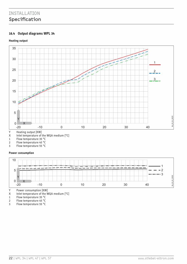
16.4 Output diagrams WPL 34
Heating output
25
35
30
20
15
10
5
0-20 -10 300 10 20 40
1
2
3
84�0
3�01
�002
9
Y Heating output [KW]X Inlet temperature of the WQA medium [°C]1 Flow temperature 35 °C2 Flow temperature 45 °C3 Flow temperature 55 °C
Power consumption
10
5
0-20 -10 300 10 20 40
123
84�0
3�01
�003
0
Y Power consumption [KW]X Inlet temperature of the WQA medium [°C]1 Flow temperature 35 °C2 Flow temperature 45 °C3 Flow temperature 55 °C

iNSTaLLaTiON Specification
www.stiebel-eltron.com WPL 34 | WPL 47 | WPL 57 | 23
Coefficient of performance (COP)
123456
-20 -10 300 10 20 40
123
84�0
3�01
�003
1
Y Coefficient of performance ε [-]X Inlet temperature of the WQA medium [°C]1 Flow temperature 35 °C2 Flow temperature 45 °C3 Flow temperature 55 °C
iNSTaLLaTiON Specification
24 | WPL 34 | WPL 47 | WPL 57 www.stiebel-eltron.com
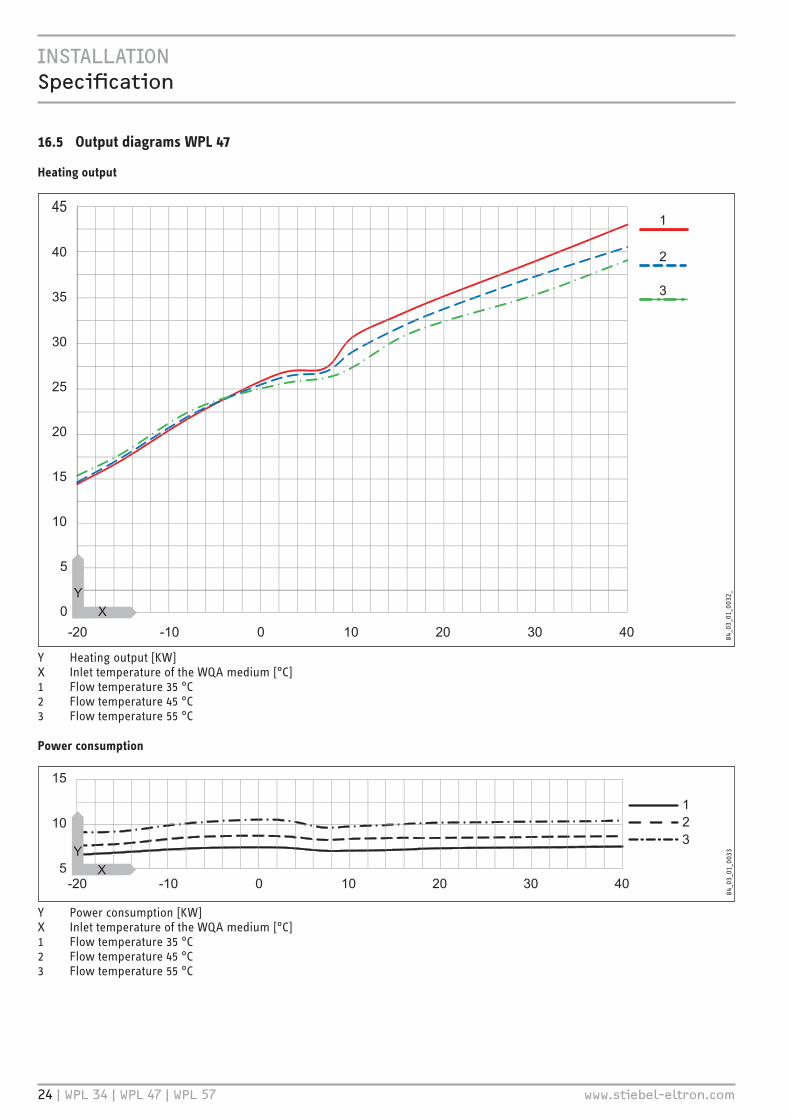
16.5 Output diagrams WPL 47
Heating output
35
45
40
30
25
20
10
5
0
15
-20 -10 300 10 20 40
1
2
3
84�0
3�01
�003
2�
Y Heating output [KW]X Inlet temperature of the WQA medium [°C]1 Flow temperature 35 °C2 Flow temperature 45 °C3 Flow temperature 55 °C
Power consumption
15
10
5-20 -10 300 10 20 40
123
84�0
3�01
�003
3
Y Power consumption [KW]X Inlet temperature of the WQA medium [°C]1 Flow temperature 35 °C2 Flow temperature 45 °C3 Flow temperature 55 °C

iNSTaLLaTiON Specification
www.stiebel-eltron.com WPL 34 | WPL 47 | WPL 57 | 25
Coefficient of performance (COP)
123456
-20 -10 300 10 20 40
123
84�0
3�01
�003
4
Y Coefficient of performance ε [-]X Inlet temperature of the WQA medium [°C]1 Flow temperature 35 °C2 Flow temperature 45 °C3 Flow temperature 55 °C

iNSTaLLaTiON Specification
26 | WPL 34 | WPL 47 | WPL 57 www.stiebel-eltron.com
16.6 Output diagrams WPL 57
Heating output
35
45
50
55
40
30
25
20
10
15
-20 -10 300 10 20 40
123
84�0
3�01
�003
5
Y Heating output [KW]X Inlet temperature of the WQA medium [°C]1 Flow temperature 35 °C2 Flow temperature 45 °C3 Flow temperature 55 °C
Power consumption
15
10
5-20 -10 300 10 20 40
123
84�0
3�01
�003
6
Y Power consumption [KW]X Inlet temperature of the WQA medium [°C]1 Flow temperature 35 °C2 Flow temperature 45 °C3 Flow temperature 55 °C

iNSTaLLaTiON Specification
www.stiebel-eltron.com WPL 34 | WPL 47 | WPL 57 | 27
Coefficient of performance (COP)
123456
-20 -10 300 10 20 40
123
84�0
3�01
�003
7
Y Coefficient of performance ε [-]X Inlet temperature of the WQA medium [°C]1 Flow temperature 35 °C2 Flow temperature 45 °C3 Flow temperature 55 °C

iNSTaLLaTiON Specification
28 | WPL 34 | WPL 47 | WPL 57 www.stiebel-eltron.com
16.7 Data tableThe output data refers to new appliances with clean heat exchangers.
The power consumption of the integral auxiliary drives represents the maximum value and may vary subject to operating point.
The power consumption of the integral auxiliary drives is included in the output details of the appliance (to EN 14511)
WPL 34 WPL 47 WPL 57 228835 228836 228837Heating outputHeating output at A10/W35 (EN 14511) kW 23.40 30.50 33.60Heating output at A7/W35 (EN 14511) kW 20.16 26.83 31.01Heating output at A2/W35 (EN 14511) kW 18.32 24.82 29.81Heating output at A-7/W35 (EN 14511) kW 15.22 21.68 24.02Heating output in silent mode at A-7/W35 max. kW 22.82Power consumptionPower consumption at A10/W35 (EN 14511) kW 8.7Power consumption at A7/W35 (EN 14511) kW 5.54 6.80 8.64Power consumption at A2/W35 (EN 14511) kW 5.83 7.24 9.03Power consumption at A-7/W35 (EN 14511) kW 5.47 7.10 8.46Power consumption, fan heating max. kW 0.65 0.65 0.65Coefficient of performanceCOP at A10/W35 (EN 14511) 3.9COP at A7/W35 (EN 14511) 3.64 3.94 3.59COP at A2/W35 (EN 14511) 3.14 3.43 3.30COP at A-7/W35 (EN 14511) 2.78 3.05 2.84Sound dataSound power level (EN 12102) dB(A) 67 67 69Max. sound power level, silent mode dB(A) - - 67Sound pressure level at 1 m distance in a free field dB(A) 59 59 61Sound pressure level at 5 m distance in a free field dB(A) 45 45 47Sound pressure level at 10 m distance in a free field dB(A) 39 39 41Application limitsMax. permissible pressure MPa 0.3 0.3 0.3Min. application limit on the heating side °C 15 15 15Max. application limit on the heating side °C 60 60 60Min. application limit, heat source °C -20 -20 -20Max. application limit, heat source °C 40 40 40Water hardness °dH ≤3 ≤3 ≤3pH value (with aluminium compounds) 8.0-8.5 8.0-8.5 8.0-8.5pH value (without aluminium compounds) 8.0-10.0 8.0-10.0 8.0-10.0Chloride mg/l <30 <30 <30Conductivity (softening) μS/cm <1000 <1000 <1000Conductivity (desalination) μS/cm 20-100 20-100 20-100Oxygen 8-12 weeks after filling (softening) mg/l <0.02 <0.02 <0.02Oxygen 8-12 weeks after filling (desalination) mg/l <0.1 <0.1 <0.1Energy dataEnergy efficiency class A+/A+ A+/A++ A+/A+Electrical dataMax. power consumption kW 10.8 13.4 15.1MCB/fuse protection, controller A 1 x B 16 1 x B 16 1 x B 16Compressor fuse/MCB A 3 x C 32 3 x C 32 3 x C 32Max. mains impedance Zmax Ω 226 226 226Phases, controller 1/N/PE 1/N/PE 1/N/PEPhases, compressor 3/N/PE 3/N/PE 3/N/PERated voltage, controller V 230 230 230Rated voltage, compressor V 400 400 400Frequency Hz 50 50 50Starting current (with/without starting current limiter) A 64/- 70/- 78/-Max. operating current A 20 22 23VersionsCondenser material 1.4401/Cu 1.4401/Cu 1.4401/CuRefrigerant R407 C R407 C R407 CDefrost type Circuit reversal Circuit reversal Circuit reversalIP rating IP14B IP14B IP14BRefrigerant charge kg 6.7 7.3 7.5
iNSTaLLaTiON Specification
www.stiebel-eltron.com WPL 34 | WPL 47 | WPL 57 | 29
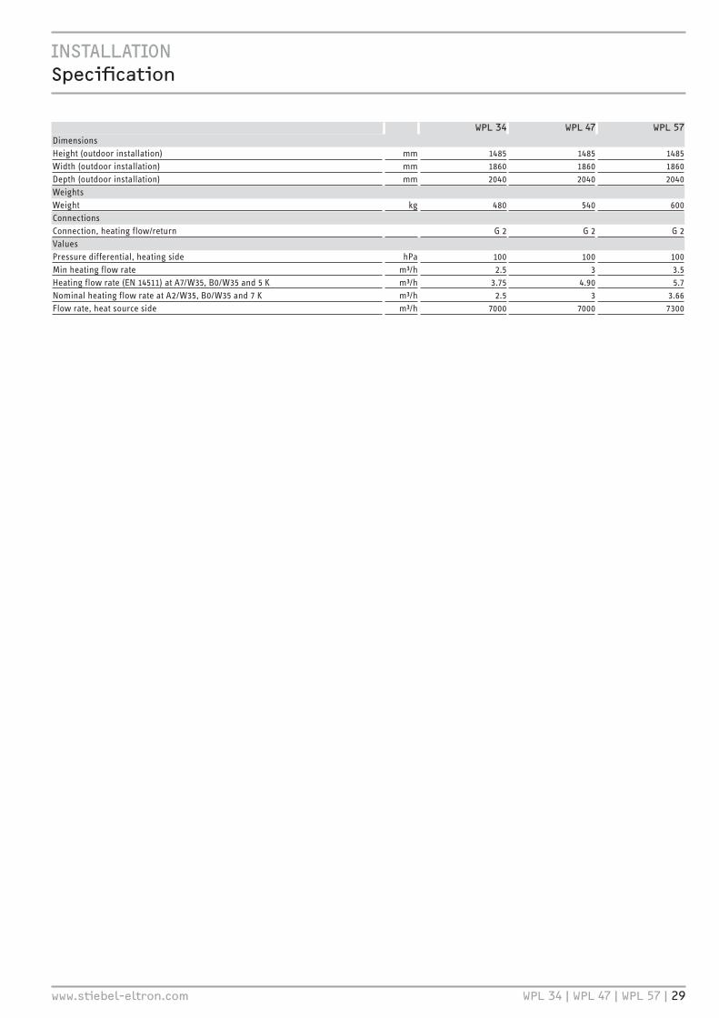
WPL 34 WPL 47 WPL 57DimensionsHeight (outdoor installation) mm 1485 1485 1485Width (outdoor installation) mm 1860 1860 1860Depth (outdoor installation) mm 2040 2040 2040WeightsWeight kg 480 540 600ConnectionsConnection, heating flow/return G 2 G 2 G 2ValuesPressure differential, heating side hPa 100 100 100Min heating flow rate m³/h 2.5 3 3.5Heating flow rate (EN 14511) at A7/W35, B0/W35 and 5 K m³/h 3.75 4.90 5.7Nominal heating flow rate at A2/W35, B0/W35 and 7 K m³/h 2.5 3 3.66Flow rate, heat source side m³/h 7000 7000 7300

30 | WPL 34 | WPL 47 | WPL 57 www.stiebel-eltron.com
GUARANTEE | ENVIRONMENT AND RECYCLING
KYOTO | R407CThis device is filled with refrigerant R407C.
Refrigerant R407C is a CFC greenhouse gas mentioned in the Kyoto protocol with a global greenhouse potential (GWP) = 1653.
Never release refrigerant R407C to atmosphere.
GuaranteeThe guarantee conditions of our German companies do not apply to appliances acquired outside of Germany. In countries where our subsidiaries sell our products a guarantee can only be issued by those subsidiaries. Such guarantee is only grant-ed if the subsidiary has issued its own terms of guarantee. No other guarantee will be granted.
We shall not provide any guarantee for appliances acquired in countries where we have no subsidiary to sell our products. This will not affect warranties issued by any importers.
Environment and recyclingWe would ask you to help protect the environment. After use, dispose of the various materials in accordance with national regulations.
GUaraNTEEENVirONmENT aND rECYCLiNG

www.stiebel-eltron.com WPL 34 | WPL 47 | WPL 57 | 31
NOTES

Deutschland STIEBEL ELTRON GmbH & Co. KG Dr.-Stiebel-Straße 33 | 37603 Holzminden Tel. 05531 702-0 | Fax 05531 702-480 [email protected] www.stiebel-eltron.de
Verkauf Tel. 05531 702-110 | Fax 05531 702-95108 | [email protected] Kundendienst Tel. 05531 702-111 | Fax 05531 702-95890 | [email protected] Ersatzteilverkauf Tel. 05531 702-120 | Fax 05531 702-95335 | [email protected]
Irrtum und technische Änderungen vorbehalten! | Subject to errors and technical changes! | Sous réserve d‘erreurs et de modifications techniques! | Onder voorbehoud van vergissingen en technische wijzigingen! | Salvo error o modificación técnica! | Excepto erro ou alteração técnica | Zastrzeżone zmiany techniczne i ewentualne błędy | Omyly a technické změny jsou vyhrazeny! | A muszaki változtatások és tévedések jogát fenntartjuk! | Отсутствие ошибок не гарантируется. Возможны технические изменения. | Chyby a technické zmeny sú vyhradené! Stand 9147
Australia STIEBEL ELTRON Australia Pty. Ltd. 6 Prohasky Street | Port Melbourne VIC 3207 Tel. 03 9645-1833 | Fax 03 9645-4366 [email protected] www.stiebel.com.au
Austria STIEBEL ELTRON Ges.m.b.H. Gewerbegebiet Neubau-Nord Margaritenstraße 4 A | 4063 Hörsching Tel. 07221 74600-0 | Fax 07221 74600-42 [email protected] www.stiebel-eltron.at
Belgium STIEBEL ELTRON bvba/sprl 't Hofveld 6 - D1 | 1702 Groot-Bijgaarden Tel. 02 42322-22 | Fax 02 42322-12 [email protected] www.stiebel-eltron.be
China STIEBEL ELTRON (Guangzhou) Electric Appliance Co., Ltd. Rm 102, F1, Yingbin-Yihao Mansion, No. 1 Yingbin Road Panyu District | 511431 Guangzhou Tel. 020 39162209 | Fax 020 39162203 [email protected] www.stiebeleltron.cn
Czech Republic STIEBEL ELTRON spol. s r.o. K Hájům 946 | 155 00 Praha 5 - Stodůlky Tel. 251116-111 | Fax 235512-122 [email protected] www.stiebel-eltron.cz
Finland STIEBEL ELTRON OY Kapinakuja 1 | 04600 Mäntsälä Tel. 020 720-9988 [email protected] www.stiebel-eltron.fi
France STIEBEL ELTRON SAS 7-9, rue des Selliers B.P 85107 | 57073 Metz-Cédex 3 Tel. 0387 7438-88 | Fax 0387 7468-26 [email protected] www.stiebel-eltron.fr
Hungary STIEBEL ELTRON Kft. Gyár u. 2 | 2040 Budaörs Tel. 01 250-6055 | Fax 01 368-8097 [email protected] www.stiebel-eltron.hu
Japan NIHON STIEBEL Co. Ltd. Kowa Kawasaki Nishiguchi Building 8F 66-2 Horikawa-Cho Saiwai-Ku | 212-0013 Kawasaki Tel. 044 540-3200 | Fax 044 540-3210 [email protected] www.nihonstiebel.co.jp
Netherlands STIEBEL ELTRON Nederland B.V. Daviottenweg 36 | 5222 BH 's-Hertogenbosch Tel. 073 623-0000 | Fax 073 623-1141 [email protected] www.stiebel-eltron.nl
Poland STIEBEL ELTRON Polska Sp. z O.O. ul. Działkowa 2 | 02-234 Warszawa Tel. 022 60920-30 | Fax 022 60920-29 [email protected] www.stiebel-eltron.pl
Russia STIEBEL ELTRON LLC RUSSIA Urzhumskaya street 4, building 2 | 129343 Moscow Tel. 0495 7753889 | Fax 0495 7753887 [email protected] www.stiebel-eltron.ru
Slovakia TATRAMAT - ohrievače vody s.r.o. Hlavná 1 | 058 01 Poprad Tel. 052 7127-125 | Fax 052 7127-148 [email protected] www.stiebel-eltron.sk
Switzerland STIEBEL ELTRON AG Industrie West Gass 8 | 5242 Lupfig Tel. 056 4640-500 | Fax 056 4640-501 [email protected] www.stiebel-eltron.ch
Thailand STIEBEL ELTRON Asia Ltd. 469 Moo 2 Tambol Klong-Jik Amphur Bangpa-In | 13160 Ayutthaya Tel. 035 220088 | Fax 035 221188 [email protected] www.stiebeleltronasia.com
United Kingdom and Ireland STIEBEL ELTRON UK Ltd. Unit 12 Stadium Court Stadium Road | CH62 3RP Bromborough Tel. 0151 346-2300 | Fax 0151 334-2913 [email protected] www.stiebel-eltron.co.uk
United States of America STIEBEL ELTRON, Inc. 17 West Street | 01088 West Hatfield MA Tel. 0413 247-3380 | Fax 0413 247-3369 [email protected] www.stiebel-eltron-usa.com
A 28
9441
-394
48-9
151
B 2
8943
7-39
448-
9151
4<AMHCMN=ijeebf>