operation and maintenance manual - … a location ... maintenance for conventional catalytic...
TRANSCRIPT
AUTHORIZED DISTRIBUTOR:GasDetectorsUSA.com - Houston, Texas [email protected]
Operation and Maintenance Manual
GDS-IR Infrared Sensor for Combustible Gases & CO2
- 832-615-3588

GDS-IR Infrared Sensor Operation and Maintenance Manual, Revision 2.1
GDS Corp Page 2 [email protected]
CAUTION: FOR SAFETY REASONS THIS EQUIPMENT MUST BE OPERATED AND
SERVICED BY QUALIFIED PERSONNEL ONLY. READ AND UNDERSTAND INSTRUCTION
MANUAL COMPLETELY BEFORE OPERATING OR SERVICING.
ATTENTION: POUR DES RAISONS DE SÉCURITÉ, CET ÉQUIPEMENT DOIT ÊTRE UTILISÉ,
ENTRETENU ET RÉPARÉ UNIQUEMENT PAR UN PERSONNEL QUALIFIÉ. ÉTUDIER LE
MANUE D’INSTRUCTIONS EN ENTIER AVANT D’UTILISER, D’ENTRETENIR OU DE
RÉPARER L’ÉQUIPEMENT.
REVISION HISTORY
Revision 2.0 5/31/13 Initial rewrite for GDS-IR
Revision 2.1 5/4/14 Update
Copyright © 2013 GDS Corp. All Rights Reserved
P/N 1200-0731-021

GDS-IR Infrared Sensor Operation and Maintenance Manual, Revision 2.1
GDS Corp Page 3 [email protected]
CONTENTS 1 SAFETY INFORMATION ................................................................................................................................................. 5
2 GENERAL INFORMATION .............................................................................................................................................. 6
INTRODUCTION .............................................................................................................................................................. 6
GETTING STARTED ........................................................................................................................................................... 6
3 SPECIFICATIONS ........................................................................................................................................................... 7
4 INFRARED DETECTION FUNDAMENTALS ...................................................................................................................... 9
5 INSTALLATION ............................................................................................................................................................ 10
SELECTING A LOCATION .................................................................................................................................................. 10
MOUNTING THE GDS-IR ............................................................................................................................................... 10
POWER & SIGNAL WIRING ............................................................................................................................................... 11
USE IN HAZARDOUS AREAS ............................................................................................................................................. 11
GETTING STARTED ......................................................................................................................................................... 11
6 CALIBRATION ............................................................................................................................................................. 12
CALIBRATION OVERVIEW ................................................................................................................................................ 12
HARDWARE ZERO ......................................................................................................................................................... 12
GENERALIZED CALIBRATION PROCEDURE ........................................................................................................................... 12
7 OPERATION AND MAINTENANCE ............................................................................................................................... 14
NORMAL OPERATION .................................................................................................................................................... 14
MAINTENANCE ............................................................................................................................................................. 14
CLEANING THE GDS-IR OPTICS .......................................................................................................................................... 14
8 TROUBLESHOOTING ................................................................................................................................................... 16
DOES NOT START PROPERLY – UNIT CYCLES ON AND OFF ....................................................................................................... 16
OUTPUT INDICATES FAULT CONDITION (< 4 MA) ................................................................................................................. 16
EXCESSIVE ZERO DRIFT ................................................................................................................................................... 16
INCORRECT READING WITH SPAN GAS ................................................................................................................................ 16
9 SPARE PARTS .............................................................................................................................................................. 17
10 DRAWINGS AND DIMENSIONS ................................................................................................................................... 19
GDS-IR Infrared Sensor Operation and Maintenance Manual, Revision 2.1
GDS Corp Page 4 [email protected]
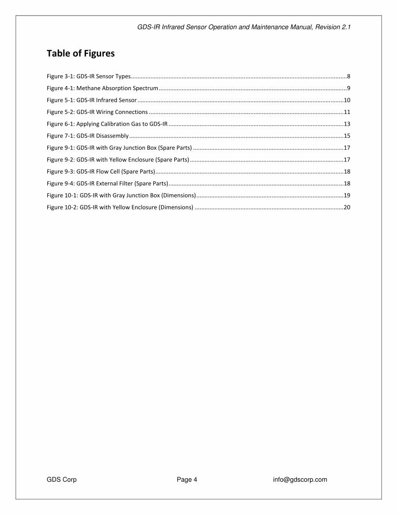
Table of Figures Figure 3-1: GDS-IR Sensor Types .................................................................................................................................... 8
Figure 4-1: Methane Absorption Spectrum ................................................................................................................... 9
Figure 5-1: GDS-IR Infrared Sensor .............................................................................................................................. 10
Figure 5-2: GDS-IR Wiring Connections ....................................................................................................................... 11
Figure 6-1: Applying Calibration Gas to GDS-IR ........................................................................................................... 13
Figure 7-1: GDS-IR Disassembly ................................................................................................................................... 15
Figure 9-1: GDS-IR with Gray Junction Box (Spare Parts) ............................................................................................ 17
Figure 9-2: GDS-IR with Yellow Enclosure (Spare Parts) .............................................................................................. 17
Figure 9-3: GDS-IR Flow Cell (Spare Parts) ................................................................................................................... 18
Figure 9-4: GDS-IR External Filter (Spare Parts) ........................................................................................................... 18
Figure 10-1: GDS-IR with Gray Junction Box (Dimensions) .......................................................................................... 19
Figure 10-2: GDS-IR with Yellow Enclosure (Dimensions) ........................................................................................... 20

GDS-IR Infrared Sensor Operation and Maintenance Manual, Revision 2.1
GDS Corp Page 5 [email protected]
1 SAFETY INFORMATION
Important – Read Before Installation Users should have a detailed understanding of GDS-IR operating and maintenance instructions. Use the GDS-IR
only as specified in this manual or detection of gases and the resulting protection provided may be impaired. Read
the following WARNINGS prior to use.
WARNINGS • The GDS-IR sensor transmitter described in this manual must be installed, operated and maintained in
accordance with information contained herein. Installation in any hazardous area must comply with all
applicable restrictions, requirements and guidelines for said hazardous areas. It is the end user customer’s
final decision to ensure that the GDS-IR is suitable for the intended use.
• The GDS-IR is designed and constructed to measure the level of certain gases in ambient air. Accuracy in
atmospheres containing steam or inert gases cannot be guaranteed.
• GDS Corp recommends mounting the sensor vertically or horizontally. Do not mount the sensor upside
down.
• Do not paint sensor assembly.
• Do not operate the GDS-IR if its enclosure is damaged or cracked or has missing components. Make sure
the cover, internal PCB’s and field wiring are securely in place before applying power.
• Do not expose the GDS-IR to electrical shock or continuous severe mechanical shock. Protect the GDS-IR
and related sensor assemblies from dripping liquids and high power sprays.
• Calibrate with known target gas at start-up and check on a regular schedule, at least every 90 days. More
frequent inspections are encouraged to spot problems such as dirt, oil, paint, grease or other foreign
materials on the sensor head.
• Periodically test for correct operation of the system’s alarm events by exposing the monitor to a targeted
gas concentration above the High Alarm set point.
• Use only for applications described within this manual.
• Like any infrared detector, the GDS-IR cannot detect combustible levels of hydrogen gas.
GDS-IR Infrared Sensor Operation and Maintenance Manual, Revision 2.1
GDS Corp Page 6 [email protected]
2 GENERAL INFORMATION
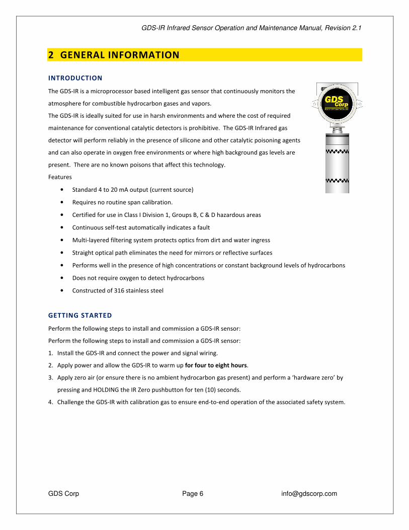
INTRODUCTION
The GDS-IR is a microprocessor based intelligent gas sensor that continuously monitors the
atmosphere for combustible hydrocarbon gases and vapors.
The GDS-IR is ideally suited for use in harsh environments and where the cost of required
maintenance for conventional catalytic detectors is prohibitive. The GDS-IR Infrared gas
detector will perform reliably in the presence of silicone and other catalytic poisoning agents
and can also operate in oxygen free environments or where high background gas levels are
present. There are no known poisons that affect this technology.
Features
• Standard 4 to 20 mA output (current source)
• Requires no routine span calibration.
• Certified for use in Class I Division 1, Groups B, C & D hazardous areas
• Continuous self-test automatically indicates a fault
• Multi-layered filtering system protects optics from dirt and water ingress
• Straight optical path eliminates the need for mirrors or reflective surfaces
• Performs well in the presence of high concentrations or constant background levels of hydrocarbons
• Does not require oxygen to detect hydrocarbons
• Constructed of 316 stainless steel
GETTING STARTED
Perform the following steps to install and commission a GDS-IR sensor:
Perform the following steps to install and commission a GDS-IR sensor:
1. Install the GDS-IR and connect the power and signal wiring.
2. Apply power and allow the GDS-IR to warm up for four to eight hours.
3. Apply zero air (or ensure there is no ambient hydrocarbon gas present) and perform a ‘hardware zero’ by
pressing and HOLDING the IR Zero pushbutton for ten (10) seconds.
4. Challenge the GDS-IR with calibration gas to ensure end-to-end operation of the associated safety system.
GDS-IR Infrared Sensor Operation and Maintenance Manual, Revision 2.1
GDS Corp Page 7 [email protected]
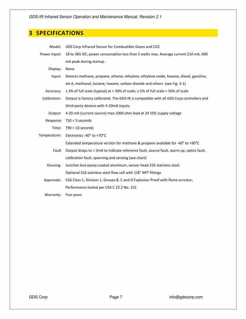
3 SPECIFICATIONS
Model: GDS Corp Infrared Sensor for Combustible Gases and CO2
Power Input: 18 to 36V DC; power consumption less than 5 watts max. Average current 210 mA, 400
mA peak during startup.
Display: None
Input:
Detects methane, propane, ethane, ethylene, ethylene oxide, hexane, diesel, gasoline,
Jet A, methanol, butane, hexane, carbon dioxide and others (see Fig. 3-1)
Accuracy: ± 3% of full scale (typical) at < 50% of scale; ± 5% of full scale > 50% of scale
Calibration: Output is factory calibrated. The GDS-IR is compatible with all GDS Corp controllers and
third-party devices with 4-20mA inputs.
Output: 4-20 mA (current source) max.1000 ohm load at 24 VDC supply voltage
Response
Time:
T50 < 5 seconds
T90 < 10 seconds
Temperature: Electronics -40° to +70°C
Extended temperature version for methane & propane available for -40° to +90°C
Fault Output drops to < 3mA to indicate reference fault, source fault, warm up, optics fault,
calibration fault, spanning and zeroing (see chart)
Housing: Junction box epoxy-coated aluminum, sensor head 316 stainless steel.
Optional 316 stainless steel flow cell with 1/8” NPT fittings
Approvals:
CSA Class 1, Division 1, Groups B, C and D Explosion Proof with flame arrestor;
Performance tested per CSA C 22.2 No. 152
Warranty: Five years

GDS-IR Infrared Sensor Operation and Maintenance Manual, Revision 2.1
GDS Corp Page 8 [email protected]
Type Target Gas Temperature Comments
108 Ethane, 0-100% LEL -40°C to + 60°C
109 Acetylene, 0-100% LEL -40°C to + 60°C
110 Methane, 0-100% LEL -40°C to + 60°C
1HT Methane, 0-100% LEL -40°C to + 90°C Extended Temperature Range
111 Propane 0-100% LEL -40°C to + 60°C
112 Isobutane 0-100% LEL -40°C to + 60°C
113 Pentane 0-100% LEL -40°C to + 60°C
114 Cyclopentane 0-100% LEL -40°C to + 60°C
115 n-Butane 0-100% LEL -40°C to + 60°C
116 Ethanol 0-100% LEL -40°C to + 60°C
117 Methanol 0-100% LEL -40°C to + 60°C
118 Propylene 0-100% LEL -40°C to + 60°C
119 Ethylene 0-100% LEL -40°C to + 60°C
120 Hexane 0-100% LEL -40°C to + 60°C
121 Jet-A 0-100% LEL -40°C to + 60°C
122 Diesel 0-100% LEL -40°C to + 60°C
123 Gasoline 0-100% LEL -40°C to + 60°C
124 Isopropyl Alcohol 0-100% LEL -40°C to + 60°C
125 Acetone 0-100% LEL -40°C to + 60°C
126 p-Xylene 0-100% LEL -40°C to + 60°C
127 Ethylene Oxide 0-50% LEL -40°C to + 60°C
128 MEK 0-100% LEL -40°C to + 60°C
129 Styrene, 0-50% LEL -40°C to + 60°C
130 Methane 0-100% by volume -40°C to + 60°C
131 Propane 0-100% by volume -40°C to + 60°C
132 Carbon Dioxide 0-5% v/v -40°C to + 60°C
133 Carbon Dioxide 0-3.5% v/v -40°C to + 60°C
Figure 3-1: GDS-IR Sensor Types

GDS-IR Infrared Sensor Operation and Maintenance Manual, Revision 2.1
GDS Corp Page 9 [email protected]
4 INFRARED DETECTION FUNDAMENTALS
The GDS-IR Infrared gas detector uses infrared absorption to detect hydrocarbon gases. Specifically, the infrared
energy is absorbed by the hydrogen-carbon bonds found in all hydrocarbon gases, and is a result of a resonance
between the frequency of the light and the vibration characteristics of the chemical bonds. As a result, the
concentration of a gas can be approximated by the difference in transmittance between a measurement beam
that is absorbed by the target gas and a reference beam that is not absorbed. The GDS-IR uses a collimated
infrared light source that passes through a waveguide and impacts dual channel receiver. The dual channel
receiver measures the intensity of two specific wavelengths, one at an active wavelength and another at the
reference wavelength. The gas concentration is determined by a comparison of these two values.
The dual channel receiver is a single wafer, double filtered receiver with an internal optical barrier. The elements
are perfectly matched resulting in overall stability and superior performance throughout the entire temperature
range. Using a dual channel receiver ensures there is no need for special lenses or beam splitters that can become
misaligned or dirty.
Figure 4-1: Methane Absorption Spectrum
Although hydrocarbon gases all share similar hydrogen-carbon bonds, the number of bonds and the orientation in
the gas molecule will have an effect on the sensor’s response. To compensate for these differences, the GDS-IR
microprocessor is pre-programmed with a response table that converts the transmittance into a linear 4-20mA
output (See Fig. 3-1).
Active Reference
Wavelength
100%
0%
Transmittance
GDS-IR Infrared Sensor Operation and Maintenance Manual, Revision 2.1
GDS Corp Page 10 [email protected]
5 INSTALLATION
SELECTING A LOCATION
Factors such as air movement, gas density, emission sources and environmental variables affect sensor location.
Air movement by fans, prevailing winds and convection should be carefully evaluated to determine if a leak is more
likely to raise gas levels in certain areas within the facility. Vapor density of a gas determines if it will rise or fall in
air when there are no significant currents. Lighter than air gases should have the monitors mounted 12 – 18 inches
(30 – 45 cm) above the potential gas leak and heavier than air gases should be this distance below. Even though
the GDS-IR sensor transmitter is designed for rugged service, it should be protected from environmental damage
from water, snow, shock, vibration and dirt.
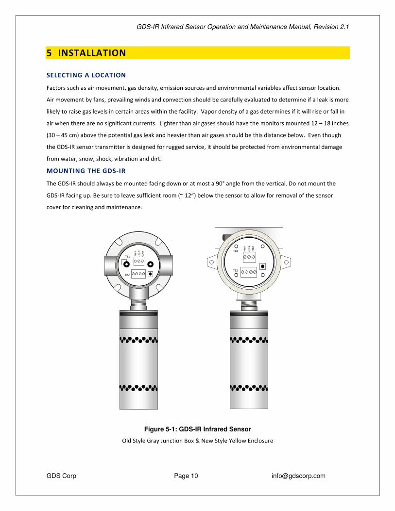
MOUNTING THE GDS-IR
The GDS-IR should always be mounted facing down or at most a 90° angle from the vertical. Do not mount the
GDS-IR facing up. Be sure to leave sufficient room (~ 12”) below the sensor to allow for removal of the sensor
cover for cleaning and maintenance.
Figure 5-1: GDS-IR Infrared Sensor
Old Style Gray Junction Box & New Style Yellow Enclosure
TB1 PWR
420
IN
COM
TB2
TB1 PWR
420
IN
COM
TB2

GDS-IR Infrared Sensor Operation and Maintenance Manual, Revision 2.1
GDS Corp Page 11 [email protected]
POWER & SIGNAL WIRING
The GDS-IR is a three-wire, DC-powered self-contained infrared sensor. The electronics require approximately 5
watts to operate properly. Connect a source of 18 to 36 VDC to TB1 “PWR” (+) and “COM” (-). The sensor’s 4-
20mA output is available on TB1 “4-20MA” (source).
Figure 5-2: GDS-IR Wiring Connections
Shielded cable is always recommended. Wiring should be installed in metal
conduit not shared by high voltage AC or DC wiring. When power is initially
applied to the GDS-IR the 4-20mA output may momentarily indicate a temporary
off-scale low (FAULT) or off-scale high (OVERRANGE) value before settling down.
USE IN HAZARDOUS AREAS
The GDS-IR is CSA certified for use in hazardous areas rated Class I Division 1, Groups B, C and D. The junction box
or yellow enclosure is also CSA certified for use in hazardous areas rated Class I Division 1, Groups B, C and D.
GETTING STARTED
Perform the following steps to install and commission a GDS-IR sensor:
5. Install the GDS-IR and connect the power and signal wiring.
6. Apply power and allow the GDS-IR to warm up for four to eight hours.
7. Apply zero air (or ensure there is no ambient hydrocarbon gas present) and perform a ‘hardware zero’ by
pressing and HOLDING the IR Zero pushbutton for ten (10) seconds.
8. Challenge the GDS-IR with calibration gas to ensure end-to-end operation of the associated safety system.
TB1 PWR
4-20
MA
COM
TB2
BLK
WHT
RED
BL
UE
IR ZERO
Pre-wired to GDS-IR: Red +24V to sensor Blue 4-20mA from sensor Black Common White Hardware Zero to sensor
GDS-IR In / Output PWR +24V In 4-20MA 4-20 mA Out COM Common
Wire Size Recommendations: Up to 500 ft. #16 AWG >500 ft. #14 AWG
Hardware Zero Pushbutton
GDS-IR Infrared Sensor Operation and Maintenance Manual, Revision 2.1
GDS Corp Page 12 [email protected]
6 CALIBRATION
CALIBRATION OVERVIEW
The GDS-IR is factory calibrated for a specific hydrocarbon gas and should only need a periodic “Hardware Zero”
approximately every six months.
Follow these GDS-IR calibration guidelines:
• Calibration accuracy is only as good as the calibration gas accuracy. GDS Corp calibration gases are
traceable to NIST standards (National Institute of Standards and Technology).
• Never use calibration gas that has passed its expiration date.
• Be sure to use ZERO AIR, a mixture of 21% oxygen and 79% nitrogen, as a zero reference unless you are
certain that no target gas exists in the area. Ambient gas may result in an ‘elevated zero’ condition that
will result in erroneous readings and may cause a FAULT to occur once the ambient gas is no longer
present.
• When using the GDS-IR with a GASMAX monitor, GDS Corp recommends using a span gas that is between
25% and 75% of full scale. GDS Corp does not recommend using full scale as the span set point.
• Always challenge a new sensor with calibration gas before depending on the device for personnel or
equipment safety
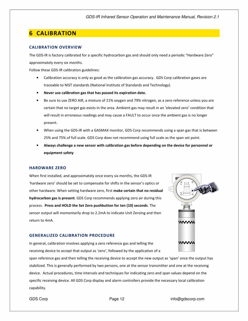
HARDWARE ZERO
When first installed, and approximately once every six months, the GDS-IR
‘hardware zero’ should be set to compensate for shifts in the sensor’s optics or
other hardware. When setting hardware zero, first make certain that no residual
hydrocarbon gas is present. GDS Corp recommends applying zero air during this
process. Press and HOLD the Set Zero pushbutton for ten (10) seconds. The
sensor output will momentarily drop to 2.2mA to indicate Unit Zeroing and then
return to 4mA.
GENERALIZED CALIBRATION PROCEDURE
In general, calibration involves applying a zero reference gas and telling the
receiving device to accept that output as ‘zero’, followed by the application of a
span reference gas and then telling the receiving device to accept the new output as ‘span’ once the output has
stabilized. This is generally performed by two persons, one at the sensor transmitter and one at the receiving
device. Actual procedures, time intervals and techniques for indicating zero and span values depend on the
specific receiving device. All GDS Corp display and alarm controllers provide the necessary local calibration
capability.
TB1 PWR
420
IN
COM
TB2

GDS-IR Infrared Sensor Operation and Maintenance Manual, Revision 2.1
GDS Corp Page 13 [email protected]
Before beginning calibration, make sure you have the following items: A cylinder of calibration gas, fixed flow
regulator and an appropriate calibration cup connected to the regulator via a length of flexible tubing. If necessary,
a cylinder of ‘zero air’ may be necessary if the absence of target gas cannot be confirmed.
The actual steps involved in calibration vary depending on the receiving device, but can be generalized as follows:
1. Select the appropriate channel on the controller or receiver and enable Calibration Mode. This should
disable alarms during the calibration process. Make sure that the controller’s Cal Span value matches the
cylinder of calibration gas.
2. Apply zero air to the sensor as shown in Fig. 6-1 or confirm the absence of any target gas.
3. At the controller or receiver, press the “Set Zero” button to confirm that the current reading is ‘zero’.
4. Apply span gas to the sensor as shown in Fig 6-1.
5. At the controller or receiver, monitor the output until it stabilizes. When stable, press the “Set Span”
button to confirm that the current reading corresponds to the Span value.
6. Turn off the regulator and remote the calibration cup from the sensor head.
7. At the controller or receiver, exit Cal Mode and resume normal operation.
Figure 6-1: Applying Calibration Gas to GDS-IR
TB PW 420
IN
CO
TB
Cylinder of Calibration Gas or “Zero Air”
Fixed Flow Regulator
Calibration Fitting

GDS-IR Infrared Sensor Operation and Maintenance Manual, Revision 2.1
GDS Corp Page 14 [email protected]
7 OPERATION AND MAINTENANCE
NORMAL OPERATION
When power is applied to the GDS-IR, it enters a one-minute warm-up period. The output current will be 0.8 mA
during the warm up time period. At the end of the warm-up period with no faults present, the GDS-IR
automatically enters normal operating mode and outputs 4.0 mA. If a fault is present after warm-up, the detector
current output will indicate a fault.
In the normal operating mode, the 4-20 mA signal level
corresponds to the detected gas concentration. In the event of an
overrange gas release, the GDS-IR will indicate an overrange
condition up to approximately 23mA. Excessive gas will not harm
the sensor and the output will return to normal once the gas
dissipates. In the event that the internal microprocessor detects a
fault condition, the output will be set to a specific mA reading that
corresponds to the type of fault detected.
MAINTENANCE
The GDS-IR should be checked regularly for damage, water ingress
or hydrophobic filter clogging due to excessive dust or dirt. If the
hydrophobic filter has become contaminated by dust, dirt or
moisture, unscrew the sensor head cover, remove the set screw
and gently slide the filter down to remove (See Fig. 7-1). Carefully
clean the filter with compressed air and reinstall. The GDS-IR can
operate without the hydrophobic filter installed if the atmosphere
contains little dust or moisture. There are no user-serviceable
components.
CLEANING THE GDS-IR OPTICS
If necessary, the GDS-IR can be partially disassembled to allow cleaning of the optical windows covering the IR
source and IR receiver. To disassemble the GDS-IR, perform the following steps (See Fig. 7-1):
1. Unscrew the outer cover in a counter-clockwise direction (looking up from underneath)
2. Locate the small set screw that holds the hydrophobic filter in place. Carefully remove the screw using a flat-
blade screwdriver.
3. Gently slide the hydrophobic filter down and set aside.
Sensor Output: 0.0 mA Unit Fault
0.2 mA Reference channel fault
0.4 mA Analytical channel fault
0.8 mA Unit warm up
1.0 mA Optics fault
1.2 mA Zero drift fault
1.6 mA Calibration fault
2.0 mA Unit spanning
2.2 mA Unit zeroing
4.0 mA Zero gas level (0%LEL)
5.6 mA (10%LEL)
8.0 mA (25%LEL)
12 mA (50%LEL)
16 mA (75%LEL)
20 mA Full scale (100% LEL)
20.1- 23 mA Over-range (> 100% LEL)

GDS-IR Infrared Sensor Operation and Maintenance Manual, Revision 2.1
GDS Corp Page 15 [email protected]
4. Place one Allen wrench in the hole marked “A” to hold the top section of the optical waveguide in place. Place
another through the hole marked “B” in the lower section of the optical waveguide. Using the two wrenches,
rotate the lower section of the optical waveguide such that it screws into the upper section. This will
eventually allow the waveguide assembly to be removed from the GDS-IR.
5. Using a cotton swab and alcohol, clean the surfaces of the Receiver and Source as shown.
6. Reassemble the GDS-IR
7. Perform a ‘hardware zero’ once the sensor is completely reassembled.
NOTE: IT IS NOT NECESSARY TO REMOVE POWER FROM THE GDS-IR TO PERFORM THIS CLEANING PROCESS.
Figure 7-1: GDS-IR Disassembly
Step 1: Unscrew Cover
Step 2: Remove setscrew and slide filter downward
Screw
Step 3: Using two Allen wrenches, unscrew optical
waveguide
Step 4: Clean surfaces with
alcohol
Source
Receiver A
B
GDS-IR Infrared Sensor Operation and Maintenance Manual, Revision 2.1
GDS Corp Page 16 [email protected]
8 TROUBLESHOOTING
DOES NOT START PROPERLY – UNIT CYCLES ON AND OFF
• Power supply cannot provide sufficient surge current for IR source power-up. Check power rating of
power supply. For example, a C2 Quad Protector Controller with standard power supply can provide
power for two GDS-IR sensors; adding a third or fourth sensor will cause the power supply to repeatedly
shut down and try to restart.
OUTPUT INDICATES FAULT CONDITION (< 4 MA)
• Reference channel fault (0.2 mA) – contact factory
• Analytical channel fault (0.4 mA) – contact factory
• Warm-up (0.8 mA) – this is normal during first one minute of operation
• Optics fault (1.0 mA) – Open and clean sensor; contact factory if fault not cleared
• Zero drift fault (1.2 mA) – Perform Hardware Zero; contact factory if fault not cleared
• Calibration fault (1.6 mA) – contact factory
EXCESSIVE ZERO DRIFT
• Hardware Zero not performed properly; perform Hardware Zero
• Hydrocarbon gas present when Hardware zero performed; perform Hardware Zero using “zero air”
reference
INCORRECT READING WITH SPAN GAS
• Receiving device scale value not set properly

GDS-IR Infrared Sensor Operation and Maintenance Manual, Revision 2.1
GDS Corp Page 17 [email protected]
9 SPARE PARTS
Figure 9-1: GDS-IR with Gray Junction Box (Spare Parts)
Figure 9-2: GDS-IR with Yellow Enclosure (Spare Parts)
TB1 PWR
420
IN
COM
TB2
TB1 PWR
420
IN
COM
TB2
Gray Junction Box with PCB 20-0100 Remote XP junction box with PCB GDS-IR 1200-0811 Replacement hydrophobic filter
Yellow Enclosure with PCB 20-0157 Full assembly less sensor (yellow) GDS-IR 1200-0811 Replacement hydrophobic filter
GDS-IR Infrared Sensor Operation and Maintenance Manual, Revision 2.1
GDS Corp Page 18 [email protected]
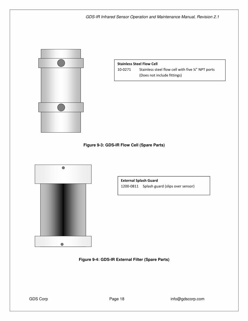
Figure 9-3: GDS-IR Flow Cell (Spare Parts)
Figure 9-4: GDS-IR External Filter (Spare Parts)
Stainless Steel Flow Cell 10-0271 Stainless steel flow cell with five ¼” NPT ports (Does not include fittings)
External Splash Guard 1200-0811 Splash guard (slips over sensor)
GDS-IR Infrared Sensor Operation and Maintenance Manual, Revision 2.1
GDS Corp Page 19 [email protected]
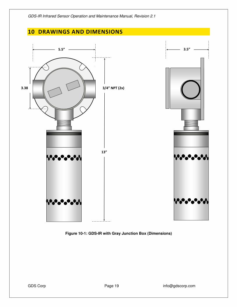
10 DRAWINGS AND DIMENSIONS
Figure 10-1: GDS-IR with Gray Junction Box (Dimensions)
TB1 PWR
420
IN
COM
TB2
13”
5.5”
3.5”
3.38”
3/4” NPT (2x)

GDS-IR Infrared Sensor Operation and Maintenance Manual, Revision 2.1
GDS Corp Page 20 [email protected]
Figure 10-2: GDS-IR with Yellow Enclosure (Dimensions)
12”
5.0” 4.21
”
3/4” NPT (2x)