operation and maintenance manual (main body) 1 diesel generator operation and maintenance manual for...
TRANSCRIPT

Page 1
Diesel Generator Operation and
Maintenance Manual For the general installation, operation and maintenance of
Diesel Engine Driven Generating Set
Serial Number:
It is essential that operation, installation and servicing of this set are only undertaken by suitably qualified
persons and should be in accordance with the recommendations of this manual.

Page 2
Table of Contents Introduction ................................................................................................................................................ 3 Additional Manuals ..................................................................................................................................... 3
Perkins Engine Manuals ................................................................................................................................................ 3 Stamford Alternator Manual ......................................................................................................................................... 3 Deep Sea Electronics Manuals ...................................................................................................................................... 3
Health and Safety precautions .................................................................................................................... 4 General Precautions ...................................................................................................................................................... 4 Starting Batteries ........................................................................................................................................................... 4 Health and Safety at Work Act (1974) ........................................................................................................................... 4 Diesel, Lubricating Oil, Coolant, Antifreeze, Battery Acid ............................................................................................. 5 Filler Cap Warnings ....................................................................................................................................................... 5 Remote Start / Stop Additional Warning ...................................................................................................................... 5 Electric Shock and First Aid Treatment ......................................................................................................................... 5
Installation of Generator............................................................................................................................. 6 Positioning of the Unit .................................................................................................................................................. 6 Preparing a Base ............................................................................................................................................................ 6 Engine Exhaust System .................................................................................................................................................. 6 Engine Fuel System........................................................................................................................................................ 7 Engine Cooling System .................................................................................................................................................. 7 Engine Lubrication ......................................................................................................................................................... 7
Before Starting ............................................................................................................................................ 8 Starting Of Set ............................................................................................................................................................... 8 Initial Test Check ........................................................................................................................................................... 9 Shutting Down Set ....................................................................................................................................................... 10
Automatic Protection Equipment ............................................................................................................. 10 Use in Automatic Mode ............................................................................................................................ 11 Table of Programmed Protection Set points in controllers ...................................................................... 12 Fault Analysis Guide .................................................................................................................................. 13 Fault Icons for DSE 7110 / DSE 7120 ......................................................................................................... 15 Battery Care and Maintenance ................................................................................................................. 16
Dry charged battery filling procedure ......................................................................................................................... 16 Care and Maintenance of wet batteries in storage ..................................................................................................... 16 Care and Maintenance of wet batteries in service ..................................................................................................... 16

Page 3
Introduction
This Instruction Manual is produced by the Service Department and is intended as a general guide for purchasers of diesel generating sets. The information given is regarded as general practice for the Company’s products, but it should be read in conjunction with the individual engine and alternator manuals supplied by the manufacturers for any particular set supplied.
NB All possible care has been taken in compiling the information contained herein, but the Company can accept no responsibility for any errors that may have occurred. The Company will welcome notification if any errors have occurred and will appreciate any suggestions for improvements. Permission should be obtained before reproducing any material appearing in the manual as it is subject to copyright. All information is believed to be correct at time of issue, but due to the rapid developments taking place in technology, changes in recommendations or practices may occur at any time.
Additional Manuals Additional manuals essential to the safe operation of this product must be downloaded and read in conjunction with the detail in this manual. Up to date copies of this manual are available from us by emailing [email protected]
Perkins Engine Manuals As of March 2013, Perkins no longer suppliers operation manuals with the engines, you can download the engine manual in many alternative languages from http://www.perkins.com/manuals/.
Stamford Alternator Manual A paper copy of the Stamford manual is included in your generator pack.
Deep Sea Electronics Manuals Multiple manuals explaining the operation, configuration and installation of Deep Sea Electronics controllers are available online from http://www.deepseaplc.com, after registration.

Page 4
Health and Safety precautions
All users of mechanical and electrical equipment will realise the importance of the health and safety of operators and others involved with such equipment. It is essential that sensible precautions are taken in this regard whenever generating sets are supplied and installed. In addition, there is considerable legislation in existence regarding this. It is impossible to specify it in detail for each country due to the complex nature and continual changes occurring, but users are advised to check special requirements in to their own country. In any event, only persons qualified to do so should install, maintain and service our equipment. The
equipment has been designed to minimize risks to the person, but there is considerable risk to personal safety if this equipment is installed, maintained or serviced by someone not fully qualified to do so.
As a minimum you should ensure
General Precautions
• Ensure that all checks are done EVERY time prior to starting, as per this manual, the engine handbook, the alternator handbook and any other documentation that comes with
the set.
• Check all mechanical connections are satisfactory every time before starting. • Check all electrical connections are correct, safely insulated and suitably earthed.
• Check service and maintenance persons are competent and adequately trained.
• Keep generating set clean and generator house tidy. • Always disconnect starter battery before commencing maintenance operations.
Starting Batteries
Handle batteries with care and in accordance with the recommendations given. When
preparing for use wear protective clothing, in particular guard the eyes. Lead acid batteries contain dilute sulphuric acid. Wash well with water if spilt and if contact
made with eyes wash well and obtain medical advice immediately. Keep battery areas well ventilated as they produce explosive gases. Avoid sparks, flames and
smoking near batteries. Break circuits before connecting or disconnecting and ensure connections are sound.
Only persons qualified to mix acid for batteries should do so, if you have not been trained in this practice, you should seek assistance from such a person.
Please read the section in the manual entitled dry charged battery filling procedure for more information regarding filling of batteries etc.
Health and Safety at Work Act (1974) The above act applies in the United Kingdom and states that:
It shall be the duty of every employer to ensure, as far as is reasonably practicable, the health, safety and welfare at work of all his employees.
It requires plant and machinery used in the United Kingdom to be properly maintained and operated so that it is safe and without risks to health of the persons concerned.
Page 5
Diesel, Lubricating Oil, Coolant, Antifreeze, Battery Acid In the United Kingdom, COSHH (Control Of Substances Hazardous to Heath) regulations cover
chemicals, products containing chemicals, fumes, dusts, vapors, mists and gases, and biological agents (germs). Operators should be trained in COSHH or the local equivalent prior
to operating such equipment.
Filler Cap Warnings Never remove the radiator filler cap while the engine is hot and the system is under pressure
because hot coolant could be discharged causing severe burns.
Remote Start / Stop Additional Warning
The module may instruct an engine start event due to external influences therefore
prior to performing any maintenance or checks on the system it is recommended that steps are taken to remove the battery and isolate supplies.
When using a set in automatic mode it is suggested that additional signage is
installed to notify all personnel that the set may start without warning.
Electric Shock and First Aid Treatment It is recommended by the company that operators should be trained for treatment of minor
injuries in accordance with local laws on first aid, with special attention to electric shock treatment.

Page 6
Installation of Generator
Only qualified persons should attempt to install this equipment. All connections should be insulated and wiring boxes and panels should be fully protected.
The Electrical Safety Regulation 2002 act (UK) should be consulted and worked in accordance with this manual and all engine and alternator handbooks where appropriate.
Positioning of the Unit Careful consideration must be given to the position of the unit. Select a position that is allows you to meet the requirements of all the other items in this section. Read each section carefully and then choose a position suitable for the generator.
Preparing a Base
A fixed concrete block is the preferred base for your set allowing the bedplate of the set to be tightly bolted down. You should allow a minimum of around 400mm surround on all sides of the set when sizing your base. The depth of the block is calculated as follows, however it is not suggested that the block is less than 4 inches thick.
𝐷 = 𝑊
𝑑𝐵𝐿
D = Depth of concrete block in feet metres W = Total weight of generating set in kg
d = Density of concrete in kg/m³) 2400kg/m³ if accurate figures are not known B = Breadth of concrete block in metres L = Length of concrete block in metres
After determining the depth of concrete required for the weight and stability of the running set the subsoil has to be checked to see if it will carry the total weight (set plus concrete block) and withstand the forces involved. If it is not possible to reach solid subsoil, hard clay, compacted sand and gravel or rock then the load must be spread using a concrete raft, the design of which should be entrusted to a qualified civil engineer.
Engine Exhaust System
Diesel Fumes
Breathing in diesel fumes can cause long term health problems or death it is therefore essential that all exhaust systems are checked for leaks regularly and exhausts are ducted out
of the building or that the set is only operated in either open or very well ventilated areas.
The exhaust system supplied with the generator is optimized to provide back pressure in accordance with the engine manufacturers instructions. If you intend to extend the length of the exhaust system beyond that of the supplier pipes you may need to increase the exhausts size as the longer the pipe the larger diameter required to ensure back pressure does not build up reducing engine performance or damaging engine components. Your engine manufacturer’s handbook should be consulted or expert advice sought in order to advise you of the correct diameters to be used.

Page 7
Engine Fuel System
If an external fuel tank or transfer system is to be used with the set then great care should be taken in selecting the correct diameter of fuel line to be used, as the longer the fuel line the larger diameter pipe that is required to avoid causing excessive pressure on the fuel pump, causing it to fail or reduce engine performance.
Fuel
Diesel fuel oil should be to specification as stated in the engine users’ handbook. It should have low sulphuric content and it is important it is clean and free from contamination. The sulphur content of the fuel will affect the oil change interval for your engine
Engine Cooling System In order to ensure your generator runs correctly without causing damage to the system it is essential that the unit is initially positioned to ensure sufficient cooling air is allowed to flow through the radiator and that the hot air is removed from the generator room and not allowed to circulate back to the generator inlet.
The cooling system must be fully filled slowly (to avoid airlocks) through the radiator cap with water and additives, both
according to the engine manual. Usually the entire system will fill by gravity but reference should be made to the engine manual supplied by the manufacturer to ensure any special taps or plugs are opened if necessary.
Some radiators require distilled or deionized water water and tap water of any quality is not usually a considered suitable alternative. Read this section in the engine handbook. Some radiators you should use approved coolant and inhibitor, check the engine manual for the correct type and mixture, coolants not recommended by the engine manufacturer are not a suitable alternative. In colder climates anti-freeze should be used, as recommended by the engine manual.
Engine Lubrication
Lubricating oil must be new, clean and of a grade suitable for the engine, which will depend on the ambient temperatures applicable and reference should be made to the engine handbook.
The engine crankcase must be filled until the level “maximum” is reached on the oil dipstick and this level may require topping up after the initial run and should be checked daily before the set is started.
Fuel & Oil Rectify any fuel or lubricating oil leaks immediately observed.
Clean up any fuel or lubrication oil spillages immediately. Avoid contact with fuel or lubricating oils. Wash fully if contact made.
All Persons should wear protective gloves.

Page 8
Before Starting Equipment supplied by the Company for use in the United Kingdom, EEC and abroad has been designed and
built to be safe and without risk to health when properly operated and when the correct precautions are observed. Failure to follow the guidance in this manual, the engine manual, the alternator manual and the
manual for the controller may result in severe damage or injury to personnel or equipment.
Before you start have you checked?
Checked all the guards are in position? The fuel, lubricating oil and water coolant levels? The frame anti-vibration mounts should be inspected for signs of corrosion? Checked that the circuit breaker is in the “OFF” position? That the fuel system is primed and bled? (See engine handbook). That all persons nearby are authorized to be present and are clear of the set.
Starting Of Set
Before attempting to start the set, all checks should be carried out as per the engine manufactures handbook by a suitably trained person.
A DSE 7000 series controller.
While all controllers in the 7000 series have different features and benefits, all the controllers have the same starting sequence. This manual covers only the basic use of the product, beyond this you should refer to the DSE
manual relevant to your controller model.
Manuals and software can be downloaded free of charge from www.deepseaelectronics.com
Page 9
Controller Model DSE 7110, DSE 7120, DSE 7210, DSE 7220, DSE 7310, DSE 7320
Starting Method Ensure the generator breaker is tripped. First ensure the controller is in Stop Mode (this clears all alarms).
Select manual mode (white button with hand symbol). Press the green button to start the set.
What will happen after you press Start?
The engine should then commence to crank and increase speed to operating level within a few seconds. If the engine does not start the module will automatically make 2 more attempts if the engine fails to start after all 3 attempts look for an obvious fault. If the fault is not obvious refer to the fault finding section.
Using the left/right arrow(s) on the module will allow you to view the different sections of information such as engine, generator and start, the up/down arrows can them be used to view the detailed information in each section, for example in the generator section you will find the generator voltage, generator frequency and generator current readings, while in the engine section you will find engine speed, oil pressure, engine temperature and battery volts. Each press will change between different pages.
The temperature of the engine does not show on the display? Like your car, until the engine temperature will not show a reading until it reaches a minimum temperature. Until the water reaches 60 degrees Celsius you won’t see anything displayed for engine temperature.
The engine should now be running at a steady governed speed without a load. The voltmeter should show a reading which may be slightly higher than the rated voltage for the set. As a routine for three phase sets the voltage should be checked to ensure that the readings are similar for each phase. Check the reading of the frequency meter (this also may
be slightly high, without any load on the set). Before the first running on load it is essential that the automatic protections are set to match any requirements of your equipment to prevent damage. See “Automatic protection Equipment”. Connection can now be made to the output load by switching the circuit breaker to the “ON” position. The engine speed may be expected to drop slightly when the load is applied but the governor should ensure the speed recovers within a few seconds. A reading of the current being supplied will now show on each of the three ammeters. This should not exceed the rated current for the set. For a three phase unit, it is important that the load is balanced.
Initial Test Check When the set is first started up it should be checked over for condition and basic performance and every time after this it should be checked to ensure that there are no leaks from the oil, fuel or water systems.
• Check there are no water leaks from the cooling system.
• Check there are no oil leaks from the lubrication system. Recheck the oil level in the engine sump.
• Check there are no fuel leaks on the supply pipes or at the fuel lift pump, injection pump or injectors.
• Check there are no fumes emitting from the exhaust system into the engine house.
• Check the engine fan is operating satisfactorily and the fan driving belt is tensioned correctly.
• Check any oil pressure gauge is reading in the order of 2.75 bar (40psi) or more.
• Check any battery charging ammeter fitted is showing a charging reading.

Page 10
General Operation Checks
Once the set has been put into operation it should have regular checks made on it. For general maintenance of the engine the operator should refer to the Users Handbooks supplied by the engine and alternator manufacturers.
Servicing & Maintenance of Set
Regular servicing and good maintenance of the generating set is of the utmost importance. Preventive maintenance should ensure long and trouble free operation of the set all of which should be done by a suitable qualified person.
Shutting Down Set
• The set should be isolated from the load by switching the circuit breaker to the “OFF” position.
• For best engine maintenance the set should be allowed to run off load for 5 minutes.
• Press the red button on the module and allow the engine to stop.
• Note that if the set has been started via the remote start input, the removal of this input while the set is on load will not shut down the unit.
Automatic Protection Equipment
The generating set will be fitted with protection devices designed to stop the engine in the event of certain faults developing. The 7110 and 7120 show icons, where are the rest of the modules will display in text the fault. The actual set points of these protections are dependent on the program within the controller. On all DSE 7000 series modules, this program can be edited from the front display. These are normally set to cover most applications and should only be altered after consultation with a member of our technical team.
Important Information on Protection Settings
The protections within the generator are designed to protect the generator from harm during normal fault conditions – they are not designed to protect equipment sensitive to voltage on your side. You should install other protections to protect your equipment from fault conditions, or adjust the parameters to suit your requirements. See the Deep sea installation instructions on the DSE website for more details on changing these parameters.
Page 11
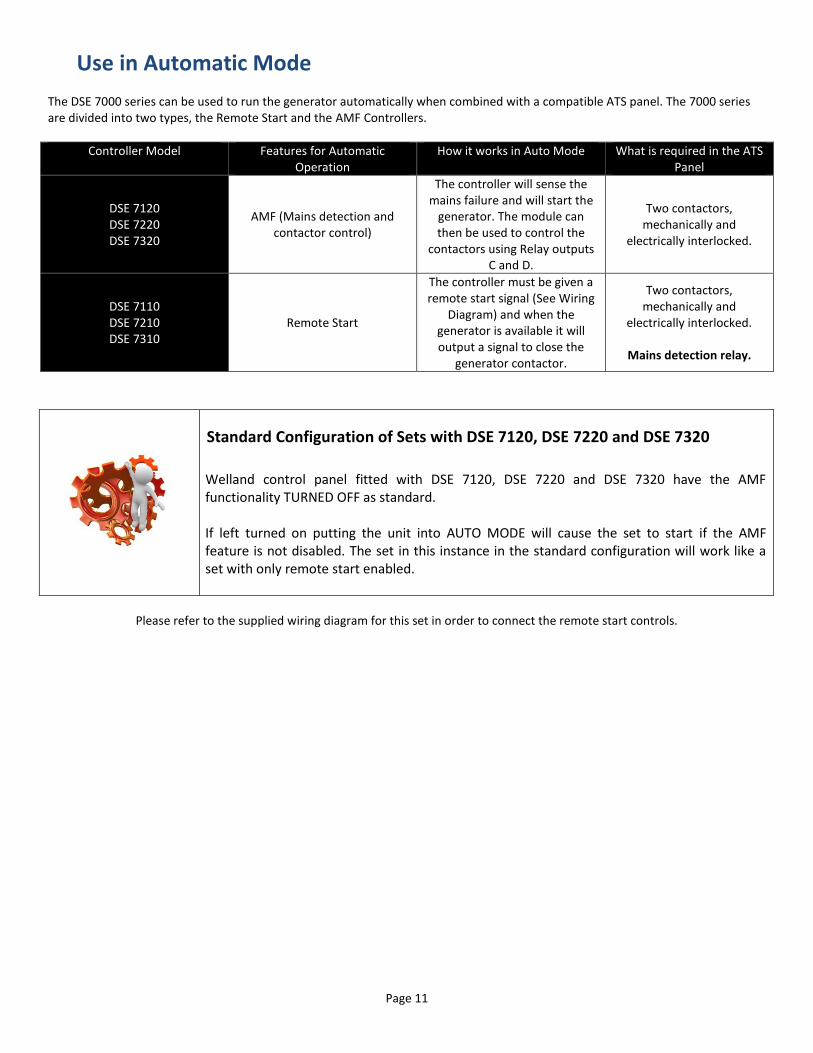
Use in Automatic Mode The DSE 7000 series can be used to run the generator automatically when combined with a compatible ATS panel. The 7000 series are divided into two types, the Remote Start and the AMF Controllers.
Controller Model Features for Automatic Operation
How it works in Auto Mode What is required in the ATS Panel
DSE 7120 DSE 7220 DSE 7320
AMF (Mains detection and contactor control)
The controller will sense the mains failure and will start the
generator. The module can then be used to control the
contactors using Relay outputs C and D.
Two contactors, mechanically and
electrically interlocked.
DSE 7110 DSE 7210 DSE 7310
Remote Start
The controller must be given a remote start signal (See Wiring
Diagram) and when the generator is available it will output a signal to close the
generator contactor.
Two contactors, mechanically and
electrically interlocked.
Mains detection relay.
Standard Configuration of Sets with DSE 7120, DSE 7220 and DSE 7320
Welland control panel fitted with DSE 7120, DSE 7220 and DSE 7320 have the AMF functionality TURNED OFF as standard. If left turned on putting the unit into AUTO MODE will cause the set to start if the AMF feature is not disabled. The set in this instance in the standard configuration will work like a set with only remote start enabled.
Please refer to the supplied wiring diagram for this set in order to connect the remote start controls.
Page 12
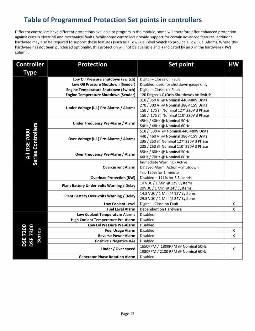
Table of Programmed Protection Set points in controllers Different controllers have different protections available to program in the module, some will therefore offer enhanced protection against certain electrical and mechanical faults. While some controllers provide support for certain advanced features, additional hardware may also be required to support these features (such as a Low Fuel Level Switch to provide a Low Fuel Alarm). Where this hardware has not been purchased optionally, this protection will not be available and is indicated by an X in the hardware (HW) column.
Controller Type
Protection Set point HW
All
DSE
70
00
Se
ries
Co
ntr
olle
rs
Low Oil Pressure Shutdown (Switch) Low Oil Pressure Shutdown (Sender)
Digital – Closes on Fault Disabled, used for shutdown gauge only.
Engine Temperature Shutdown (Switch) Engine Temperature Shutdown (Sender)
Digital – Closes on Fault 120 Degrees C (Only Shutdowns on Switch)
Under Voltage (L-L) Pre-Alarms / Alarms
310 / 350 V @ Nominal 440-480V Units 270 / 300 V @ Nominal 380-415V Units 150 / 175 @ Nominal 127~220V 3 Phase 150 / 175 @ Nominal 110~220V 3 Phase
Under Frequency Pre-Alarm / Alarm 45Hz / 40Hz @ Nominal 50Hz 54Hz / 48Hz @ Nominal 60Hz
Over Voltage (L-L) Pre-Alarms / Alarms
510 / 530 V @ Nominal 440-480V Units 440 / 460 V @ Nominal 380-415V Units 235 / 250 @ Nominal 127~220V 3 Phase 235 / 250 @ Nominal 110~220V 3 Phase
Over Frequency Pre-Alarm / Alarm 55Hz / 60Hz @ Nominal 50Hz 66Hz / 70Hz @ Nominal 60Hz
Overcurrent Alarm Immediate Warning - Active Delayed Alarm Action – Shutdown Trip 120% for 1 minute
Overload Protection (KW) Disabled – 111% for 5 Seconds
Plant Battery Under-volts Warning / Delay 10 VDC / 1 Min @ 12V Systems 20VDC / 1 Min @ 24V Systems
Plant Battery Over-volts Warning / Delay 14.8 VDC / 1 Min @ 12V Systems 29.5 VDC / 1 Min @ 24V Systems
Low Coolant Level Digital – Close on Fault X
Fuel Level Alarm Dependant on Hardware X
DSE
72
00
D
SE 7
30
0
Seri
es
Low Coolant Temperature Alarms Disabled
High Coolant Temperature Pre-Alarm Disabled
Low Oil Pressure Pre-Alarm Disabled
Fuel Usage Alarm Disabled X
Reverse Power Alarm Disabled X
Positive / Negative VAr Disabled
Under / Over speed 1650RPM / 1800RPM @ Nominal 50Hz 1980RPM / 2100 RPM @ Nominal 60Hz
X
Generator Phase Rotation Alarm Disabled
Page 13
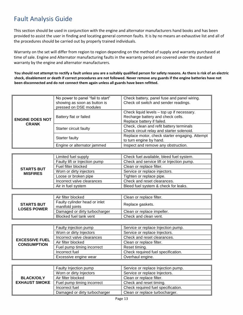
Fault Analysis Guide
This section should be used in conjunction with the engine and alternator manufacturers hand books and has been provided to assist the user in finding and locating general common faults. It is by no means an exhaustive list and all of the procedures should be carried out by properly trained individuals. Warranty on the set will differ from region to region depending on the method of supply and warranty purchased at time of sale. Engine and Alternator manufacturing faults in the warranty period are covered under the standard warranty by the engine and alternator manufacturers. You should not attempt to rectify a fault unless you are a suitably qualified person for safety reasons. As there is risk of an electric shock, disablement or death if correct procedures are not followed. Never remove any guards if the engine batteries have not been disconnected and do not connect them again unless all guards have been refitted.
ENGINE DOES NOT CRANK
No power to panel “fail to start” showing as soon as button is pressed on DSE modules
Check battery, panel fuse and panel wiring. Check oil switch and sender readings.
Battery flat or failed Check liquid levels – top up if necessary. Recharge battery and check cells. Replace battery if failed.
Starter circuit faulty Check, clean and refit battery terminals Check circuit relay and starter solenoid.
Starter faulty Replace motor, check starter engaging. Attempt to turn engine by hand.
Engine or alternator jammed Inspect and remove any obstruction.
STARTS BUT MISFIRES
Limited fuel supply Check fuel available, bleed fuel system.
Faulty lift or Injection pump Check and service lift or Injection pump.
Fuel filter blocked Clean or replace filter.
Worn or dirty injectors Service or replace injectors.
Loose or broken pipe Tighten or replace pipe.
Incorrect valve clearances Check and reset clearances.
Air in fuel system Bleed fuel system & check for leaks.
STARTS BUT LOSES POWER
Air filter blocked Clean or replace filter.
Faulty cylinder head or inlet manifold joints
Replace gaskets.
Damaged or dirty turbocharger Clean or replace impeller.
Blocked fuel tank vent Check and clean vent.
EXCESSIVE FUEL CONSUMPTION
Faulty injection pump Service or replace Injection pump.
Worn or dirty Injectors Service or replace Injectors.
Incorrect valve clearances Check and reset clearances.
Air filter blocked Clean or replace filter.
Fuel pump timing incorrect Reset timing.
Incorrect fuel Check required fuel specification.
Excessive engine wear Overhaul engine.
BLACK/OILY EXHAUST SMOKE
Faulty Injection pump Service or replace Injection pump.
Worn or dirty Injectors Service or replace Injectors.
Air filter blocked Clean or replace filter.
Fuel pump timing incorrect Check and reset timing.
Incorrect fuel Check required fuel specification.
Damaged or dirty turbocharger Clean or replace turbocharger.
Page 14
Excessive engine load Reduce load as necessary.
Long running time on light load Run on full load for one hour period.
BLUE/WHITE EXHAUST SMOKE
Wrong grade of lubricating oil Check required grade and replace.
Excessive engine wear Overhaul engine.
Head gasket failure Replace head gasket.
LOW OIL PRESSURE
Low oil level in sump Add oil to the correct level.
Oil pressure switch or sender faulty Test or replace switch or sender.
Oil filter blocked Replace oil filter.
Faulty relief valve Clean or replace valve.
Oil pump worn Replace oil pump.
HIGH ENGINE TEMPERATURE
Low level of coolant Refill radiator and check for leaks.
Faulty thermostat Check thermostat and replace if necessary.
Fan belt slipping Adjust tension of belt or replace if damaged.
Radiator matrix blocked Clean matrix thoroughly.
Blockage in cooling system Drain system flush out and refill.
Low level of lubricating oil Check and top up to correct level.
Injection pump timing incorrect Check and reset timing.
Cylinder head gasket failed Remove head and replace gasket.
Cooling fan damaged Replace fan.
ENGINE TURNS BUT DOES NOT
FIRE
No fuel at atomizers Check fuel available in tank and that fuel valves / taps are open.
Air in fuel system Bleed fuel system & check for air leaks.
Dirt or water in fuel Drain & clean fuel system & replace fuel filters.
Faulty lift or Injection pump Check and service lift or Injection pump.
Injection timing incorrect Reset timing (engine fires but fails to start)
Fuel filter blocked Clean or replace filter.
Air filter blocked Clean or replace filter.
Worn or dirty injectors Service or replace injectors.
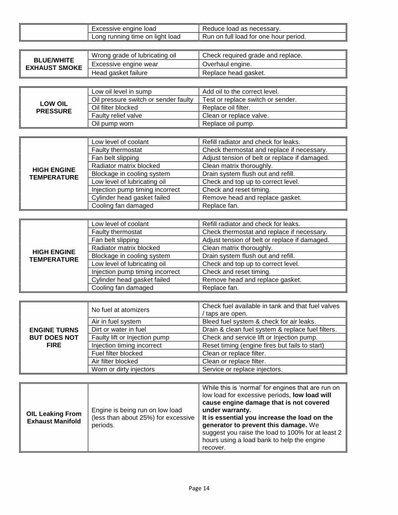
OIL Leaking From Exhaust Manifold
Engine is being run on low load (less than about 25%) for excessive periods.
While this is ‘normal’ for engines that are run on low load for excessive periods, low load will cause engine damage that is not covered under warranty. It is essential you increase the load on the generator to prevent this damage. We suggest you raise the load to 100% for at least 2 hours using a load bank to help the engine recover.

Page 15
Fault Icons for DSE 7110 / DSE 7120 The DSE 7110 and 7120 have an icon based display, which will show the following icons in the event of a shutdown event. The 7210, 7220, 7310 and 7320 all support text display. The following is extracted from the Deep sea manual.

Page 16
Battery Care and Maintenance
Dry charged battery filling procedure
• Keep all batteries in a dry charged condition until they are required for service.
• Shelf life of dry charged batteries is only around 2 years (prior to activation) unless they are vacuum sealed.
• Always handle batteries with care, ensuring that the correct personal safety protection is used at all times e.g. face mask, goggles, rubber / PVC gloves and apron…etc. If there is any contact of acid with the eyes or skin, then the affected area should be thoroughly washed with clean water and medical attention obtained immediately.
• When activation is required, remove and discard any form of sealing plugs or foil. Do not dispose of the filler caps as they will have to be replaced over the tops of the filler holes before the product goes into service.
• Inspect the battery casing to ensure that there is no damage. If damage is found DO NOT fill the battery.
• Fill all of the cells with new battery grade dilute sulphuric acid of a specific gravity 1.270 to 1.280, to 6mm above the tops of the separators.
• If there is any spillage of acid, then this should be neutralised immediately with alkali (soda ash, sodium carbonate), washed down with water and scrubbed with a hard brush. All spillages must be contained, do not allow to enter main drainage.
• The temperature of the acid and the battery should be between 10°C and 20°C.
• After 30 minutes check the level of the acid to ensure that tops of the separators are still covered by 6mm if not, top up with dilute acid.
• Charge the battery with a good quality battery charger, ensuring that the correct voltage / current is used as defined by the battery manufacturer (with regards to the product specifications). It is advisable to leave the filler caps off the battery during the initial charge.
• After completion of charge the battery be stood for 12 hours. After this period check the levels of acid within the cells, if they have fallen below 6mm from the tops of the separators then top up the correct level with distilled water.
• Check that the battery voltage is above 12.7v for 12 volt batteries, 25.4V for 6 volt batteries, charge more if required.
• If after further charging the voltage is still low, investigate further, a faulty battery must not be put into service!
• Thoroughly clean the battery to remove any acid from the casing and replace the filler caps.
• For storage purposes of wet charged batteries, it is important that all products are always stored upright, on a clean dry smooth base in a well-ventilated and cool area. Never smoke or allow naked flames within the vicinity of a battery as any gasses given off could ignite.
• Never allow tools to be placed/fall across the tops of the battery as this could result in a short circuit between the terminals.
• Never try to repair a damaged battery, Never try to remove acid from a battery
Care and Maintenance of wet batteries in storage
• Once a battery has been filled and charged it begins to die. Rotate batteries in stock using the ‘first in – first out’ principle.
• Always store batteries in an upright position, on a clean dry smooth base in a well-ventilated and cool area.
• The shelf life is dependent on the temperature. A battery stored at 25°C may only last 2 months before the voltage drops below the required state of charge, however when stored at 5°C this could increase to above 9 months.
• Before fitting, check the open circuit voltage, if below 12.7, recharge the battery
• Always smear the terminals with a thin layer of petroleum jelly when fitting to any application. This will help prevent corrosion.
• Remove any metallic objects from the hands and wrist (watches, rings..etc) when fitting a battery.
• When fitting a battery, always connect the ‘earth’ terminal last. When removing a battery always disconnect the ‘earth’ terminal first.
• Ensure that the battery tray / housing is free from any small particles that could puncture the case when the battery is secured in place.
• Do not over tighten any battery hold downs or clamping frames as this could result in damage to the battery casing.
Care and Maintenance of wet batteries in service
Where batteries are fitted in hot climates, or in a very demanding applications it is important to check the batteries every month to ensure that there is sufficient electrolyte (dilute sulphuric acid as used in lead-acid batteries) within the cells. A check of the casing/terminals is advisable.
• Remove the battery filler caps and ensure that the electrolyte is 6mm over the tops of the separators. If not, top up with water. Never use acid. When a battery gasses and the volume of electrolyte reduces, all that is lost is the water content. As the electrolyte reduces in volume it becomes stronger. So water is required to revert back to the correct volume and density.
• Check terminals and clamps for any corrosion, remove using boiling water and wire brush. Use petroleum jelly to protect terminals.
• Check that there is no damage to the casing. If damage is found then remove the battery immediately. Investigate the cause of the damage and take the appropriate corrective action.