operation and maintenance manual pump maintenance..... 19 8. inverter reference guide - ip20...
TRANSCRIPT

ScubaTANK WX (Smart Control Panel)
Operation and Maintenance Manual

Table of Contents
2
Table of Contents1. Important Safety Information................................................................................................................................. 32. Specifications ................................................................................................................................................................ 53. Installation Sequence................................................................................................................................................. 74. Commissioning.......................................................................................................................................................... 125. Pressure Vessel.......................................................................................................................................................... 166. User Maintenance .................................................................................................................................................... 187. XPW Pump Maintenance....................................................................................................................................... 198. Inverter Reference Guide - IP20 Version.......................................................................................................... 21
Dutypoint LimitedShepherd Road
GloucesterGL2 5EL
United Kingdom
Important Safety Information
1 Important Safety Information
1.1 Health & Safety at Work Act 1974Section 6(a) of this Act requires manufacturers to advise their customers on the safety and the handling precautions to be observed when installing, operating, maintaining and servicing their products. The user’s attention is therefore drawn to the following:– The appropriate sections of this manual must be read before working on the equipment.– Installation, operating and maintenance must only be carried out by suitably trained/qualified personnel.– Normal safety precautions must be taken and appropriate procedures observed to avoid accidents.
Refer to Dutypoint for any technical advice or product information. It is the responsibility of the customer and/or the contractor:– To ensure that anyone working on the equipment is wearing all necessary protective gear/clothing;– Is aware of appropriate health & safety warnings and to read the information in this manual.
1.2 Mechanical Device Servicing– Familiarise yourself with the relevant contents of this manual– Installation, maintenance and repair work must only be carried out by trained, skilled and suitably qualified personnel.– Disconnect or lock-out the power source to ensure that the item(s) will remain inoperative. Locking out the equipment by
switching off the release mechanism or set value WILL NOT prevent accidental starting.– Allow the item(s) to cool if over-heated.– CLOSE the isolating valves on the suction and discharge connections of the affected item(s).– If working on pump, VENT slowly and cautiously – Refer to the relevant section of this manual.– DRAIN the pump(s).
1.3 Pump Hand Control Mode (Where Fitted)In the 'HAND' position the pump(s) controlled by the switch will normally run at full speed and completely independently of any control devices, and can result in pump(s) running against a closed valve head if there is no draw. This can cause the system to be maintained at the maximum pressure produced by the pump plus any incoming pressure and additional pressure caused by water surge and can potentially damage the pump and other parts of the system.The 'HAND' option should only be used with a competent operator in attendance, or when there is a continued demand sufficient to provide constant flow through the pumps to maintain the running pressure of the system to an acceptable level.
1.4 Electrical Safety - High VoltagesThis information is especially applicable when Variable Speed Controllers (Inverters) are fitted to pumps.When the inverter variable speed drive head is connected to the power supply the components of the power unit as well as certain components of the master control unit – are also connected to the power supply.
TOUCHING THESE COMPONENTS CAN SERIOUSLY ENDANGER LIFE!
— Before removing the frequency inverter cover, the system must be disconnected from the power supply— After switching off the power supply wait at least 5 minutes before starting work on or in the inverter drive head - the
capacitors in the intermediate circuit must be given time to discharge completely via the discharge restors.
3
Important Safety Information
UP TO 800V CAN BE PRESENT - IF THERE ARE FAULTS THIS CAN BE HIGHER
— All work carried out when the frequency inverter is open must be performed only by suitably qualified and properly authorised personnel.
THE SYSTEM MUST ONLY BE OPERATED WHEN IT HAS BEEN CORRECTLY EARTHED AND PIPES BONDED TO EARTH IN ACCORDANCE WITH IEE REGULATIONS
— When connecting external control wires care must be taken not to short circuit adjacent components. Bare cable ends which are not in use must be insulated.
1.5 Electronic Safety Devices– Inverter drives contain electronic safety devices which switch off the control element in the event of a fault developing.– A motor can also be stopped by ‘mechanical blocking’– If it is switched off electronically, the motor is disconnected from the mains voltage supply via the electronics in the inverter
drive.– Voltage fluctuation and power failures (temporary outages) can cause the motor to switch itself off.
A MOTOR WILL HAVE ZERO CURRENT BUT WILL REMAIN ENERGISED AS IT STOPS
— Take necessary precautions - the motor is not voltage-free in the circuit itself
REPAIR OF FAULTS CAN CAUSE ITEMS TO START UP AGAIN UNEXPECTEDLY
— Ensure the motor is isolated before commencing any work
HIGH VOLTAGE TESTS OF INVERTERS MAY DAMAGE THE ELECTRICAL COMPONENTS.
— Bridge before the incoming/outgoing terminals L-L2-L3 and U-V-W.— To avoid incorrect metering by capacitors incorporated in the electronic circuits, isolate the motor from the inverter drive
head.
4

Specifications
2 Specifications
Table 1: ScubaTANK WX Range Specifications
2.1 Identifying ScubaTANK ModelsFigure 1: ScubaTANK Model Codes
Applications Water with no gas or aggressive substancesFlow Range 0.8 - 3.1 litres/sec
Pressure Range 2.0 - 7.0 barLiquid Temperature 1°C - 23°C
Ambient Temperature +5°C - +40°C for indoor installationsHumidity Max 50%
Controller Type Modus VASCOProtection Low water level via probe control
Tank ConstructionGRP construction
25mm insulation (HCFC and CFC free)Base reinforced with encapsulated multi-ply board and fitted with fixing brackets
Tank Capacity 175l, 375l, 490l, 650l, 800l, 1,050l, 1,250l, 1,650l or 2,250lInlet Valve ¾” or 1” high flow solenoid valve
Discharge WX1 models: 1¼” BSPWX2 models: 1½” BSP
Pressure Vessel 12 litre stainless steel
WX2-5040-490-AB-HS-RM/2Product Prefix
Number of PumpsPump Model
Tank Actual Capacity (litres)Options:
AB = Category 5 AB air gapHS = Horizontally split tank
RM = Control panel supplied loose for remote mounting/2 = Twin Tank System
5
Specifications
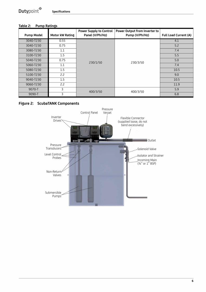
Table 2: Pump Ratings
Figure 2: ScubaTANK Components
Pump Model Motor kW RatingPower Supply to Control
Panel (V/Ph/Hz)Power Output from Inverter to
Pump (V/Ph/Hz) Full Load Current (A)3040-T230 0.55
230/1/50 230/3/50
4.13040-T230 0.75 5.23080-T230 1.1 7.43100-T230 1.5 5.55040-T230 0.75 5.05060-T230 1.1 7.45080-T230 1.5 10.55100-T230 2.2 9.09040-T230 1.5 10.59060-T230 2.2 11.9
9070-T 3400/3/50 400/3/50
5.99090-T 3 6.8
Control PanelPressure Vessel
Flexible Connector (supplied loose, do not
bend excessively)
Outlet
Solenoid Valve
Isolator and StrainerIncoming Main (¾” or 1” BSP)
Inverter Drives
Pressure Transducers
Level Control Probes
Non-Return Valves
Submersible Pumps
6
Installation Sequence
3 Installation Sequence
3.1 Position and Secure the Tank1) Connect the inlet water supply via an isolation valve;2) Connect the overflow system to a suitable drain;3) Connect the warning pipe (where fitted) and pipe to a suitable location;4) Connect the outlet pipe;5) Connect the electrical supply cable from a fused supply with correct rating - see ScubaTANK Breaker Ratings;6) Fill the system and vent the pump;7) Test and commission.
NOTE: The ScubaTANK must be installed on a stable, level surface or plinth capable of supporting the tank and liquid.See ScubaTANK Dimensions and Weights
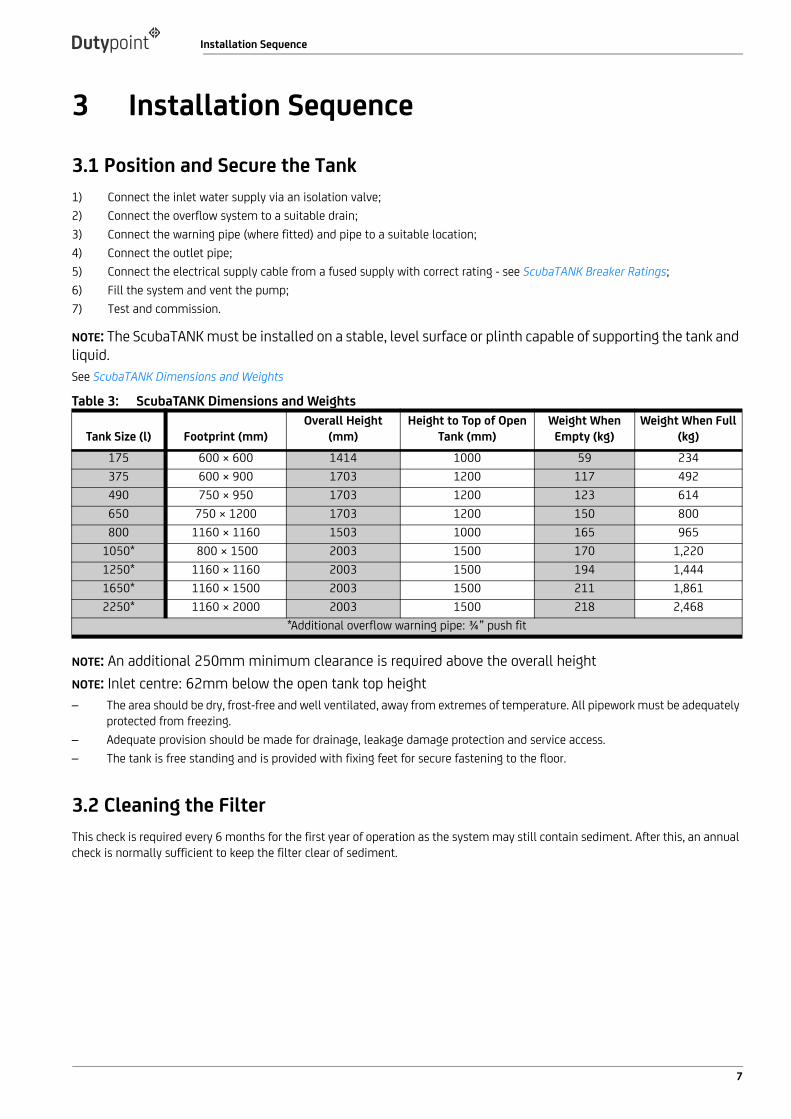
Table 3: ScubaTANK Dimensions and Weights
NOTE: An additional 250mm minimum clearance is required above the overall heightNOTE: Inlet centre: 62mm below the open tank top height– The area should be dry, frost-free and well ventilated, away from extremes of temperature. All pipework must be adequately
protected from freezing.– Adequate provision should be made for drainage, leakage damage protection and service access.– The tank is free standing and is provided with fixing feet for secure fastening to the floor.
3.2 Cleaning the FilterThis check is required every 6 months for the first year of operation as the system may still contain sediment. After this, an annual check is normally sufficient to keep the filter clear of sediment.
Tank Size (l) Footprint (mm)Overall Height
(mm)Height to Top of Open
Tank (mm)Weight When
Empty (kg)Weight When Full
(kg)175 600 × 600 1414 1000 59 234375 600 × 900 1703 1200 117 492490 750 × 950 1703 1200 123 614650 750 × 1200 1703 1200 150 800800 1160 × 1160 1503 1000 165 965
1050* 800 × 1500 2003 1500 170 1,2201250* 1160 × 1160 2003 1500 194 1,4441650* 1160 × 1500 2003 1500 211 1,8612250* 1160 × 2000 2003 1500 218 2,468
*Additional overflow warning pipe: ¾” push fit
7
Installation Sequence
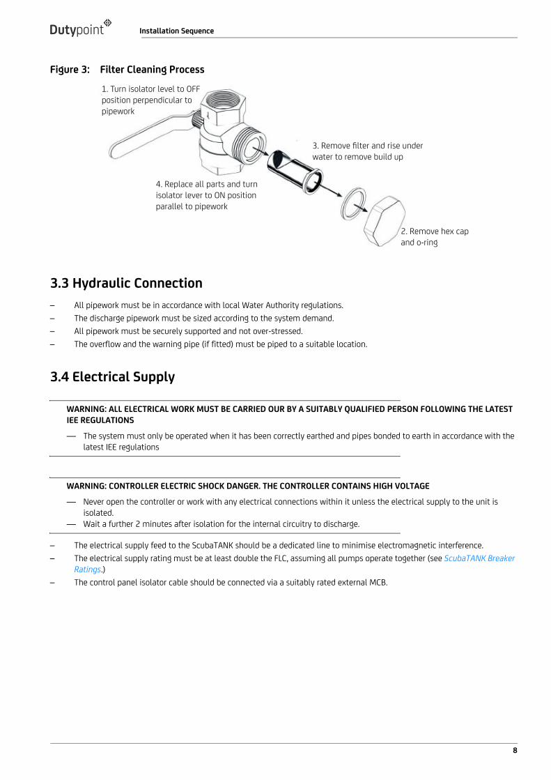
Figure 3: Filter Cleaning Process
3.3 Hydraulic Connection– All pipework must be in accordance with local Water Authority regulations.– The discharge pipework must be sized according to the system demand.– All pipework must be securely supported and not over-stressed.– The overflow and the warning pipe (if fitted) must be piped to a suitable location.
3.4 Electrical Supply
WARNING: ALL ELECTRICAL WORK MUST BE CARRIED OUR BY A SUITABLY QUALIFIED PERSON FOLLOWING THE LATEST IEE REGULATIONS
— The system must only be operated when it has been correctly earthed and pipes bonded to earth in accordance with the latest IEE regulations
WARNING: CONTROLLER ELECTRIC SHOCK DANGER. THE CONTROLLER CONTAINS HIGH VOLTAGE
— Never open the controller or work with any electrical connections within it unless the electrical supply to the unit is isolated.
— Wait a further 2 minutes after isolation for the internal circuitry to discharge.
– The electrical supply feed to the ScubaTANK should be a dedicated line to minimise electromagnetic interference.– The electrical supply rating must be at least double the FLC, assuming all pumps operate together (see ScubaTANK Breaker
Ratings.)– The control panel isolator cable should be connected via a suitably rated external MCB.
1. Turn isolator level to OFFposition perpendicular topipework
2. Remove hex capand o-ring
3. Remove filter and rise underwater to remove build up
4. Replace all parts and turnisolator lever to ON positionparallel to pipework
8

Installation Sequence
Table 4: ScubaTANK Breaker Ratings
NOTE: The probe relay settings are factory preset and should conform with information in the wiring diagram. Adjustment will invalidate the warranty.
Figure 4: Volt Free Contact Wiring Details
3.5 How to Seal a Horizontal Split Tank (Where Applicable)This section applies only to ScubaTANK WX models with horizontal split tanks. These have the -HS designation.
WARNING: THE FLANGE SEALANT IS VERY ADHESIVE
— Ensure it is aligned correctly before applying it to the flange.— Remove paper backing as you progress along the flanges— Check that you have the correct number of fixing components, i.e. nut, bolt, washers and arboseal.— Ensure the flanges are free from grease and grit or other substances which may damage or prevent the flange sealant
from sticking,— Ensure the flange sealant black strip is applied approx 5mm from the inner edge of the flange, water side.
NOTE: Ensure you follow the procedure according the images and instructions below.
Pump Model Pump FLCSingle Pump
ScubaTANK ModelTwin Pump
ScubaTANK ModelWX1 (Single Pump)
Breaker RatingWX2 (Twin Pump)
Breaker Rating3040 4.1 WX1-3040-xxx WX2-3040-xxx 10 (1~) 20 (1~)3060 5.2 WX1-3060-xxx WX2-3060-xxx 10 (1~) 20 (1~)3080 7.4 WX1-3080-xxx WX2-3080-xxx 10 (1~) 20 (1~)3100 5.5 WX1-3100-xxx WX2-3100-xxx 10 (1~) 20 (1~)5040 5.0 WX1-5040-xxx WX2-5040-xxx 10 (1~) 20 (1~)5060 7.4 WX1-5060-xxx WX2-5060-xxx 10 (1~) 20 (1~)5080 10.5 WX1-5080-xxx WX2-5080-xxx 10 (1~) 20 (1~)5100 9.0 WX1-5100-xxx WX2-5100-xxx 16 (1~) 32 (1~)9040 10.5 WX1-9040-xxx WX2-9040-xxx 10 (1~) 20 (1~)9060 11.9 WX1-9060-xxx WX2-9060-xxx 16 (1~) 32 (1~)9070 5.9 WX1-9070-xxx WX2-9070-xxx 16 (3~) 32 (3~)9090 6.8 WX1-9090-xxx WX2-9090-xxx 16 (3~) 32 (3~)
MAXIMUM 230V - 5AMP
2× BLACK FROM
INVERTER
2× RED FROM
INVERTER
VOLT FREE CONNECTION
1 2
9

Installation Sequence
Figure 5: Applying split tank sealant
3.6 Bolt Tightening Sequence for Split Tank Flange AssemblyAfter all the nuts have been spun onto the bolts by hand, you may begin tightening sequentially from the first bolt to its diagonal opposite and continue in a clockwise or anticlockwise direction.1) First time around, just pinch the nuts with a spanner;2) Second time around, apply 30% recommended torque;3) Third time around, apply 60% recommended torque;4) Fourth time around, apply 100% recommended torque.
3.7 Level Probe DetailsThere are 5 terminals within the probe holder:
Nut and bolt arrangement. Ensure flanges are clean and free from grease, grit etc.
Apply flange sealant ensuring the black strip is water side.
When applying sealant to the next flange, ensure a overlap.
Flange sealant overlaps like this.
DO NOT LEAVE A GAP BETWEEN SEALS
✓ ×
Note: some sealant may squeeze out from between the flanges. This is normal.
10

Installation Sequence
Table 5: ScubaTANK Level Probe Holder Details
Figure 6: ScubaTANK Probes
Table 6: ScubaTANK Level Probe Lengths
E1 Solenoid Cut-Off Probe Shortest probe (300mm)E2 Solenoid Cut-In Probe 100mm longer than the cut out probeE3 Low Level Probe 50mm shorter than the common probeE4 Common Probe Longest probeE5 Note used in standard ScubaTANK models
ScubaTANK Capacity (l) 175, 800 375, 490, 650 1050, 1250 , 1650, 2250E4 Common Probe Length (mm) PR-6-890 - 890mm PR-6-1090 - 1090mm PR-6-1390 - 1390mmE3 Low Level Probe Length (mm) PR-6-840 840mm PR-6-1040 - 1040mm PR-6-1340 - 1340mm
E2 Solenoid Cut-In Probe Length (mm) PR-6-400 400mm PR-6-400 - 400mm PR-6-400 - 400mmE1 Solenoid Cut-Out Probe Length (mm) PR-6-300 300mm PR-6-300 - 300mm PR-6-300 - 300mm
E1
E2
E4
E3
E1E2
E3 E4
E5
11
Commissioning
4 Commissioning
4.1 Installation and Commissioning OverviewBefore shipment, all Dutypoint pump sets are pre-commissioned. Whilst important procedures such as venting and rotational direction checks need to be carried out on site, initial parameters including pressure settings and delay timers will be adjusted to suit the site conditions previously advised to Dutypoint.In practice, a system can almost invariably be made to perform more efficiently if further re-commissioning is carried out on site.Please note that engineer visits by Dutypoint are priced at one visit to commission one pump set. If there are multiple units on a site, special terms can be negotiated. To arrange a commissioning visit, please call the Technical Service Help line 01452 300590.The following checks should be carried out at the initial installation before any run tests are performed.
WARNING
— Ensure that you have read and understood Important Safety Information.
4.2 Pipework and mechanical components1) Ensure that the mounting area and any associated groundwork provides adequate support for the pump set.2) Ensure all supports/brackets are in place and secure.3) Verify all pipe joints are sealed and tight.
4.3 Electrical
WARNING
— These checks MUST be carried out by a competent electrician.— Ensure that the power source is sufficient to allow the running of two (twin pump sets) or three (triple pump sets) pumps
together.
1) Check the motor voltage and frequency information on all the motor nameplates and on controllers etc. correspond withthat of the source power supply.
2) Check that all electrical connections are correctly made and secure. Pay particular attention to Earth and bonding connec-tions.
3) Carry out specific checks for Earth bonding.4) Carry out NICEIC certification checks as required for the installation, e.g Earth Loop Impedance, Insulation Tests, etc.5) Carry out any other pre-start checks recommended by the pump manufacturer. Refer to the pump manual in the Appendix
of this manual. DO NOT POWER UP AT THIS STAGE.
4.4 Low Level Float Switch Wiring (Optional)Terminal 1 and 3 require a normally closed contact in order to allow the pump set to operate. To facilitate this the unit will be supplied with a wire loop between 1 and 2. To install a low level float switch this loop has to be removed and the float switch wired to operate as an open on fail scenario.If 2 or more float switches are required (due to twin compartment or multiple tanks) all float switches are wired into terminals 1 and 2 in parallel.
12
Commissioning
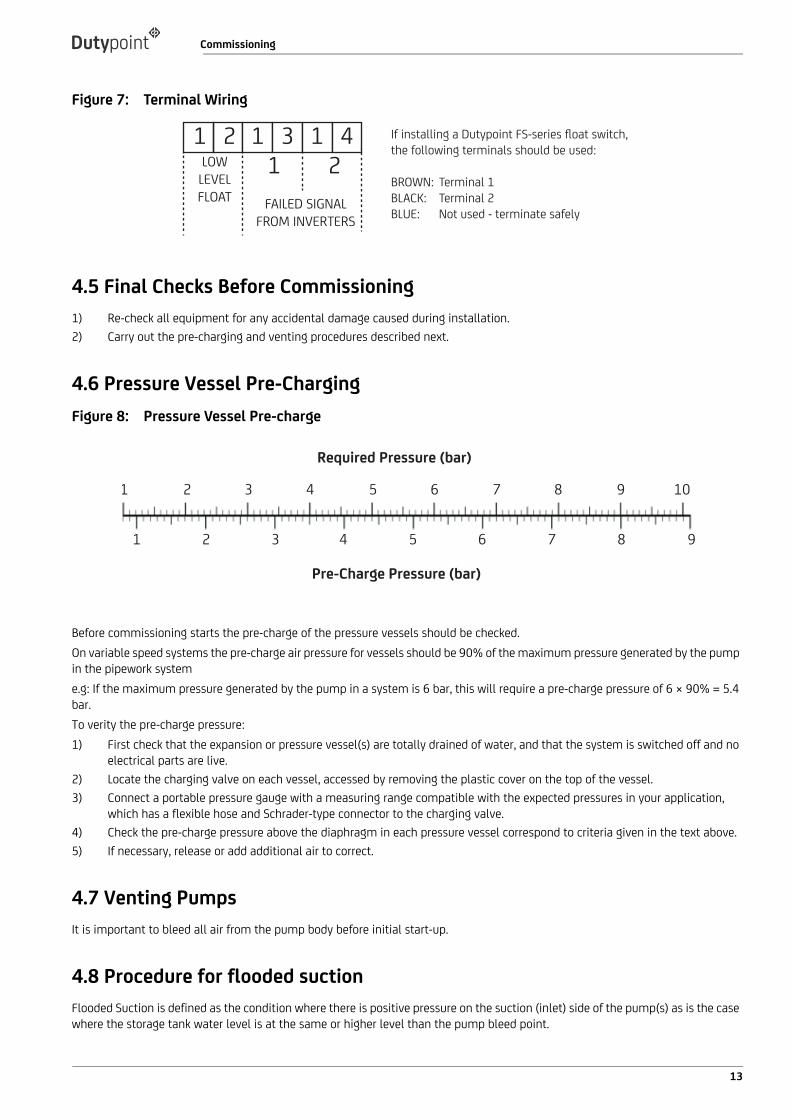
Figure 7: Terminal Wiring
4.5 Final Checks Before Commissioning1) Re-check all equipment for any accidental damage caused during installation.2) Carry out the pre-charging and venting procedures described next.
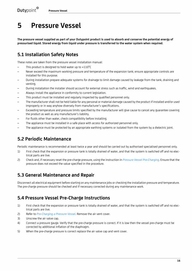
4.6 Pressure Vessel Pre-ChargingFigure 8: Pressure Vessel Pre-charge
Before commissioning starts the pre-charge of the pressure vessels should be checked.On variable speed systems the pre-charge air pressure for vessels should be 90% of the maximum pressure generated by the pump in the pipework systeme.g: If the maximum pressure generated by the pump in a system is 6 bar, this will require a pre-charge pressure of 6 × 90% = 5.4 bar.To verity the pre-charge pressure:1) First check that the expansion or pressure vessel(s) are totally drained of water, and that the system is switched off and no
electrical parts are live.2) Locate the charging valve on each vessel, accessed by removing the plastic cover on the top of the vessel.3) Connect a portable pressure gauge with a measuring range compatible with the expected pressures in your application,
which has a flexible hose and Schrader-type connector to the charging valve.4) Check the pre-charge pressure above the diaphragm in each pressure vessel correspond to criteria given in the text above.5) If necessary, release or add additional air to correct.
4.7 Venting PumpsIt is important to bleed all air from the pump body before initial start-up.
4.8 Procedure for flooded suctionFlooded Suction is defined as the condition where there is positive pressure on the suction (inlet) side of the pump(s) as is the case where the storage tank water level is at the same or higher level than the pump bleed point.
If installing a Dutypoint FS-series float switch, the following terminals should be used:
BROWN: Terminal 1BLACK: Terminal 2BLUE: Not used - terminate safely
1 1 12 3 4LOW
LEVEL FLOAT FAILED SIGNAL
FROM INVERTERS
1 2
1 32 4 5 6 7 8 9 10
1 32 4 5 6 7 8 9
Required Pressure (bar)
Pre-Charge Pressure (bar)
13

Commissioning
This procedure should be carried out individually for each pump in the pump set.1) Open all valves on the suction (inlet) side of the pump.2) Using the vent screw at the top of the pump (refer to Appendix to locate), allow any air in the pump body and suction pipe-
work to vent to atmosphere.3) When water (under pressure from the storage tank feeding the pump on the suction side) escapes through the vent screw
hole - and no more air bubbles can be seen - close the vent screw.4) Switch on the electrical supply to the pump motor and start the pump in AUTO mode. As each motor starts verify that the
direction of rotation correctly corresponds with the direction of the arrow shown on the body of the pump. If rotation is back-ward STOP, switch off the pump and investigate.
5) Slowly open the valve on the discharge manifold outlet to the system allowing water to be pumped into the system.6) Switch off, re-close the discharge valve and repeat steps 3 to 6 several times to ensure that all air is released from the pump
body and local pipework.
The above procedure should be carried out individually for each pump in the pump set.
4.9 Procedure for Lift SuctionLift Suction is defined where the water storage tank is at a lower level than the pump set. In this case a negative pressure condition may exist at the pump suction.
WARNING: THE "LIFT SUCTION" MODE OF OPERATION REQUIRES SPECIFIC VENTING PROCEDURES.
— Please call Dutypoint Systems Technical Support on +44 (0)1452 300590 for advice before attempting to vent the pump(s).
The advised procedure should then be carried out individually for each pump in the pump set.
4.10 Programming the ControllerDutypoint Systems fit a design of Inverter/Controller that is most suitable for the design duty of the pump set.Manufacturer’s information for them is detailed in the Appendices to this manual.Carefully follow the appropriate step-by-step setting-up procedures contained in the manual, ensuring that any data required to be entered by the end user is accurately inserted where requested.If in doubt please call Dutypoint Systems Technical Support on 01452 300590 for advice.
4.11 Operation and Performance TestsHaving checked that the pump set is installed, pre-charged, vented in accordance with the procedures set out earlier, carry out the following running tests before handing over the pump set for operational use.1) Run each pump by selecting HAND (Manual) control.2) Re-select to AUTO mode.3) Create the conditions for a normal start and run and allow the selected ‘Duty’ pump to run. Whilst running observe the pres-
sure values. Verify the pump motor speeds up / slows down in accordance with the desired control philosophy.
4.12 Duty/Standby Twin Pump Sets1) On Duty/Standby sets, wait for a normal stop to take place (or create the conditions where this would happen) and check
that the ‘Duty’ pump stops. Whilst stopped simulate a fault by inhibiting the ‘Duty’ pump and then recreate the conditions for a normal start to take place. Check that the ‘Standby’ Pump now starts and runs in place of the inhibited ‘Duty’ pump and observe the pressure values. Verify that the pump motor speeds up / slows down in accordance with the desired control philosophy.
2) Wait for a normal stop to take place (or create the conditions where this would happen) and check the ‘Standby’ pump stops. Whilst stopped undo the inhibit to the ‘Duty’ pump which should now return to normal.
14

Commissioning
4.13 Duty/Assist Twin Pump Sets1) For ‘Duty/Assist’ applications, run the system up to pressure using the ‘Duty’ Pump only, then deliberately create the condi-
tion(s) which will require the ‘Assist’ Pump to operate as well. (e.g: open taps to reduce the pressure in the system to a point where one pump only cannot maintain the required output. Verify that the ‘Assist’ Pump starts and runs together with the ‘Duty’ Pump and that the desired pressure is duly restored and maintained.
2) Close the taps again (thereby reducing the demand) and check the ‘Assist’ Pump slows down and stops, allowing the ‘Duty’ Pump to continue on its own.
4.14 Commissioning/Handover Check1) Record any indicated voltage / amperage / pressure data / controller passwords for future reference.2) Re-check all isolating valves are fully open and replace any cover(s).3) With all the isolators ON and the switches and/or control programs set to AUTO, the pump set is now fully operational in
automatic control mode.
NOTE: No manual operation or attendance is required other than for routine servicing and maintenance checks. Other than for maintenance purposes, the supply to the Controller(s) and the Pump motor(s) should never be switched off.
15
Pressure Vessel
5 Pressure VesselThe pressure vessel supplied as part of your Dutypoint product is used to absorb and conserve the potential energy of pressurised liquid. Stored energy from liquid under pressure is transferred to the water system when required.
5.1 Installation Safety NotesThese notes are taken from the pressure vessel installation manual:– This product is designed to hold water up to +110°C– Never exceed the maximum working pressure and temperature of the expansion tank; ensure appropriate controls are
installed for this purpose.– During installation prepare adequate systems for drainage to limit damage caused by leakage from the tank, draining and
venting.– During installation the installer should account for external stress such as traffic, wind and earthquakes.– Always install the appliance in conformity to current legislation.– This product must be installed and regularly inspected by qualified personnel only.– The manufacturer shall not be held liable for any personal or material damage caused by the product if installed and/or used
improperly or in way anyhow diversely from manufacturer’s specifications.– Exceeding temperature and pressure limits specified by the manufacturer will give cause to cancel any guarantee covering
the product as well as any manufacturer’s liability.– For fluids other than water, check compatibility before installing.– The appliance must be installed in a safe place with access for authorized personnel only.– The appliance must be protected by an appropriate earthing systems or isolated from the system by a dielectric joint.
5.2 Periodic MaintenancePeriodic maintenance is recommended at least twice a year and should be carried out by authorised specialised personnel only.1) First check that the expansion or pressure tank is totally drained of water, and that the system is switched off and no elec-
trical parts are live.2) Check and, if necessary reset the pre-charge pressure, using the instruction in Pressure Vessel Pre-Charging. Ensure that the
pressure does not exceed the value specified in the procedure.
5.3 General Maintenance and RepairDisconnect all electrical equipment before starting on any maintenance jobs or checking the installation pressure and temperature. The pre-charge pressure should be checked and if necessary corrected during any maintenance work.
5.4 Pressure Vessel Pre-Charge Instructions1) First check that the expansion or pressure tank is totally drained of water, and that the system is switched off and no elec-
trical parts are live.2) Refer to Pre-Charging a Pressure Vessel. Remove the air vent cover.3) Unscrew the air valve cap.4) Connect a pressure gauge. Verify that the pre-charge pressure is correct. If it is low then the vessel pre-charge must be
corrected by additional inflation of the diaphragm.5) When the pre-charge pressure is correct replace the air valve cap and vent cover.
16

Pressure Vessel
Figure 9: Pre-Charging a Pressure Vessel
5.5 Diaphragm ReplacementTo replace a diaphragm:1) Empty the expansion tank2) Remove the pre-charging by releasing the air vent.3) Loosen the M8 screws fastening the flange4) Remove the flange5) Extract the diaphragm and replace it
5.6 Installing a Replacement VesselRead these instructions carefully before installing the product:1) Make sure the product is in good condition. If the product is damaged do not start on installation but take it back to the seller
for immediate replacement.2) The product must be installed in the position (vertical or horizontal) specified in the technical specifications.3) While the system is cold, measure the static pressure with a gauge, at the point where the tank has to be installed.4) Set the pre-charge pressure, using the procedure earlier in this section. Ensure that the pressure does not exceed the value
specified in the procedure.5) The appliance must be supplied with efficient and sufficient safety and control facilities, in particular the safety valve must
be connected to the appliance and be free from interference and must be gauged to the quantity of fluid to be discharged. The safety valve should also be designed to ensure that the pressure does not permanently exceed the maximum tolerated pressure (a temporary pressure peak, limited to 10% of the maximum tolerated pressure, is allowed).
6) Make sure the cap of the valve is fitted tightly after pre-loading and that there is no leakage.
2 3
4
17

User Maintenance
18
6 User MaintenanceRoutine user maintenance for Dutypoint pump sets.Dutypoint pump sets have been designed to keep major maintenance requirements to a minimum. Planned maintenance of the pumps and other principal components should therefore be undertaken at the intervals recommended in the manuals referenced below.It is essential that a full test following the Pre-Commissioning procedure on is carried out on an annual basis.In addition, the operator in charge should routinely make visual checks of the equipment during use, noting particularly any unusual noises or vibrations. This will give an immediate indication of any irregularity in the operation of the system.
DANGER: DO NOT COMMENCE ANY MAINTENANCE WORK UNTIL:
— You have read Important Safety Information— You have the appropriate personal protective equipment— You have all necessary safety equipment to hand
Refer to the appropriate manufacturer’s information that is provided in the appendices of this manual for the equipment being serviced.
Table 7: Periodic User Checks for Pump SetsTiming Checks
Weekly1) Visually check the complete pump set2) Observe the running of the pump(s) and note any unusual vibrations or sounds.
Quarterly
1) Visually check the complete pump set2) Observe the running of the pump(s) and note any unusual vibration, etc.3) Check the cooling fan and vents on the Control Unit(s) and clear any dust or other obstructions4) Operate each manual isolating valve three times to ensure continued efficient working
6-monthly The pressure vessel should be drained and the pre-charge pressure checked. See Pressure Vessel Pre-Charge Instructions for more details.
12-monthly (essential) Carry out the full pre-commissioning procedure to verify safe operation - see Commissioning.

XPW Pump Maintenance
7 XPW Pump MaintenanceThe following information is an extract from the pump manufacturer’s documentation.
7.1 Routine MaintenanceThe pump requires no detailed maintenance except to:– Periodically verify that the suction grate is clear;– Periodically with the power off, check the condition of the cables and electrical power and earth connections.
7.2 Pump Replacement
WARNING: ELECTRICAL PUMPS SHOULD NEVER BE USED OUTSIDE THE LIMITATIONS DESCRIBED IN THE TECHNICAL SPECIFICATIONS
— Replacement pumps should remain in their original packaging until installation.
ELECTRIC SHOCK DANGER
— Before beginning any work on the pump you must isolate the electrical supply and make sure that it cannot be accidentally reconnected.
— Wait for a further 2 minutes for the internal circuitry to discharge BEFORE opening or working with any electrical connections.
— It is the installer’s responsibility to ensure that the installation is in compliance with local regulations and all electrical guidelines.
7.3 Replacement Procedure1) Before installation, check the new pump and verify its integrity and that it is the correct type/rating. Contact the supplier if
there are any anomalies.2) Locate the 4× plastic screw covers protecting the M6 screws securing the tank lid. Remove the covers and screws and lift off
the tank lid to access the old pump.3) Disconnect the pump pipework.4) Disconnect the pump electrical cable, noting the cable colour coding.5) Insert the replacement pump into the tank and reconnect the pipework.6) Feed the pump cable through the watertight glands and make the electrical connections to the controller as noted in step
4 above, verifying that the earth connection is securely made.7) Fix the power cable to the delivery pipe using suitable strap.8) Replace the covers on the controller.9) Test the system, checking rotation direction (see below).10) When testing is complete, replace the tank lid and screw it down, refitting the plastic caps
WARNING: EXCESSIVE FORCE CAN DAMAGE EQUIPMENT
— To avoid damage, do not use excessive force when screwing the pipe to the pump discharge outlet.
7.4 Checking the Direction of RotationNOTE: This operation will be performed dry and must not last more than a few seconds.
19

XPW Pump Maintenance
If the direction of rotation is reversed due to incorrect connection or controller programming, the pump performance will be significantly lower than the nominal values. To verify a correct connection, proceed as follows:1) Start the electrical pump before it is submerged. Correct rotation is in a counter- clockwise direction as viewed from above.2) With the pump operating, installed and submerged, use a clamp meter to measure the current. If the rotation is reversed,
you will see values about double those indicated on the name plate.3) Correct before using the system.
7.5 VASCO Controller ServicingFor full maintenance, repair and replacement details for the VASCO controller(s), see Appendix A: VASCO Inverter O&M Manual
20
Inverter Reference Guide - IP20 Version
8 Inverter Reference Guide - IP20 VersionPlease read the IMPORTANT SAFETY INFORMATION below, and all Warning and Caution information elsewhere when carrying out any work on the inverter drives. This information is provided for reference purposes and should be not be referred to in normal operation of the product. The majority of the inverter parameters are controller by the touch screen display. If in doubt, consult Dutypoint before making any adjustments.
8.1 Important Safety Information
DANGER: RISK OF ELECTRIC SHOCK.
— This variable speed drive product is intended for professional incorporation into complete equipment or systems as part of a fixed installation. If installed incorrectly it may present a safety hazard. The system uses high voltages and currents, carries a high level of stored electrical energy, and is used to control mechanical plant that may cause injury. Close attention is required to system design and electrical installation to avoid hazards in either normal operation or in the event of equipment malfunction. Only qualified electricians are allowed to install and maintain this product.
— System design, installation, commissioning and maintenance must be carried out only by personnel who have the necessary training and experience. They must carefully read this safety information and the instructions in this Guide and follow all information regarding transport, storage, installation and use of the inverter, including the specified environmental limitations.
— Do not perform any flash test or voltage withstand test on the product. Any electrical measurements required should be carried out with the product disconnected. Internal surge arrestors are fitted, intended to protect against damage due to mains borne spikes, which will result in the product failing the flash test
— Electric shock hazard! Disconnect and ISOLATE the product before attempting any work on it. High voltages are present at the terminals and within the drive for up to 10 minutes after disconnection of the electrical supply. Always ensure by using a suitable multimeter that no voltage is present on any drive power terminals prior to commencing any work.
— Where supply to the drive is through a plug and socket connector, do not disconnect until 10 minutes have elapsed after turning off the supply.
— Ensure correct earthing connections and cable selection as per defined by local legislation or codes. The drive may have a leakage current of greater than 3.5mA; furthermore the earth cable must be sufficient to carry the maximum supply fault current which normally will be limited by the fuses or MCB. Suitably rated fuses or MCB should be fitted in the mains supply to the drive, according to any local legislation or codes.
— Do not carry out any work on the drive control cables whilst power is applied to the drive or to the external control circuits.
DANGER: RISK OF DAMAGE TO PROPERTY
— Within the European Union, all machinery in which this product is used must comply with Directive 98/37/EC, Safety of Machinery. In particular, the machine manufacturer is responsible for providing a main switch and ensuring the electrical equipment complies with EN60204-1.
— The level of integrity offered by the inverter control input functions – for example stop/start, forward/reverse and maximum speed, is not sufficient for use in safety-critical applications without independent channels of protection. All
21
Inverter Reference Guide - IP20 Version
applications where malfunction could cause injury or loss of life must be subject to a risk assessment and further protection provided where needed.
— The driven motor can start at power up if the enable input signal is present.— The STOP function does not remove potentially lethal high voltages. ISOLATE the drive and wait 10 minutes before starting
any work on it. Never carry out any work on the Drive, Motor or Motor cable whilst the input power is still applied.— The inverter can be programmed to operate the driven motor at speeds above or below the speed achieved when
connecting the motor directly to the mains supply. Obtain confirmation from the manufacturers of the motor and the driven machine about suitability for operation over the intended speed range prior to machine start up.
— Do not activate the automatic fault reset function on any systems whereby this may cause a potentially dangerous situation.
— Inverters are intended for indoor use only— When mounting the drive, ensure that sufficient cooling is provided. Do not carry out drilling operations with the drive in
place, dust and swarf from drilling may lead to damage.— The entry of conductive or flammable foreign bodies should be prevented. Flammable material should not be placed close
to the drive— Ensure that the supply voltage, frequency and no. of phases (1 or 3 phase) correspond to the rating of the inverter as
delivered.— Never connect the mains power supply to the Output terminals U, V, W.— Do not install any type of automatic switchgear between the drive and the motor. This may cause the drive protection to
activate, resulting in a trip and loss of operation.— Wherever control cabling is close to power cabling, maintain a minimum separation of 100 mm and arrange crossings at
90 degrees— Ensure that all terminals are tightened to the appropriate torque setting— Do not attempt to carry out any repair of the inverter. In the case of suspected fault or malfunction, contact Dutypoint for
further assistance.
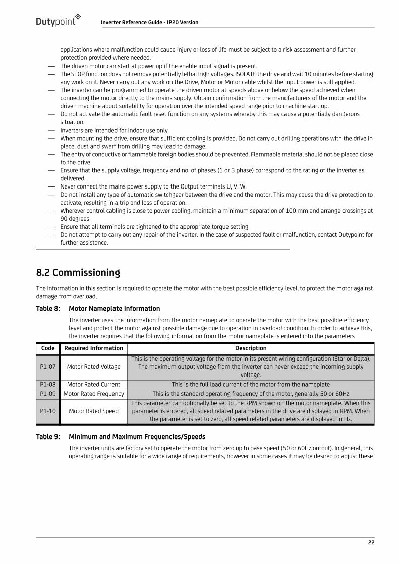
8.2 CommissioningThe information in this section is required to operate the motor with the best possible efficiency level, to protect the motor against damage from overload,
Table 8: Motor Nameplate InformationThe inverter uses the information from the motor nameplate to operate the motor with the best possible efficiency level and protect the motor against possible damage due to operation in overload condition. In order to achieve this, the inverter requires that the following information from the motor nameplate is entered into the parameters
Table 9: Minimum and Maximum Frequencies/SpeedsThe inverter units are factory set to operate the motor from zero up to base speed (50 or 60Hz output). In general, this operating range is suitable for a wide range of requirements, however in some cases it may be desired to adjust these
Code Required Information Description
P1-07 Motor Rated VoltageThis is the operating voltage for the motor in its present wiring configuration (Star or Delta).
The maximum output voltage from the inverter can never exceed the incoming supply voltage.
P1-08 Motor Rated Current This is the full load current of the motor from the nameplateP1-09 Motor Rated Frequency This is the standard operating frequency of the motor, generally 50 or 60Hz
P1-10 Motor Rated SpeedThis parameter can optionally be set to the RPM shown on the motor nameplate. When this parameter is entered, all speed related parameters in the drive are displayed in RPM. When
the parameter is set to zero, all speed related parameters are displayed in Hz.
22
Inverter Reference Guide - IP20 Version
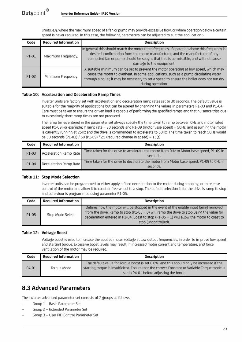
limits, e.g. where the maximum speed of a fan or pump may provide excessive flow, or where operation below a certain speed is never required. In this case, the following parameters can be adjusted to suit the application :-
Table 10: Acceleration and Deceleration Ramp TimesInverter units are factory set with acceleration and deceleration ramp rates set to 30 seconds. The default value is suitable for the majority of applications but can be altered by changing the values in parameters P1-03 and P1-04. Care must be taken to ensure the driven load is capable of performing the specified ramps and that nuisance trips due to excessively short ramp times are not produced.The ramp times entered in the parameter set always specify the time taken to ramp between 0Hz and motor rated speed P1-09.For example; If ramp rate = 30 seconds and P1-09 (motor vase speed) = 50Hz, and assuming the motor is currently running at 25Hz and the drive is commanded to accelerate to 50Hz. The time taken to reach 50Hz would be 30 seconds (P1-03) / 50 (P1-09) * 25 (required change in speed) = 15(s)
Table 11: Stop Mode SelectionInverter units can be programmed to either apply a fixed deceleration to the motor during stopping, or to release control of the motor and allow it to coast or free-wheel to a stop. The default selection is for the drive is ramp to stop and behaviour is programmed using parameter P1-05.
Table 12: Voltage BoostVoltage boost is used to increase the applied motor voltage at low output frequencies, in order to improve low speed and starting torque. Excessive boost levels may result in increased motor current and temperature, and force ventilation of the motor may be required.
8.3 Advanced ParametersThe inverter advanced parameter set consists of 7 groups as follows:– Group 1 – Basic Parameter Set– Group 2 – Extended Parameter Set– Group 3 – User PID Control Parameter Set
Code Required Information Description
P1-01 Maximum Frequency.
In general this should match the motor rated frequency. If operation above this frequency is desired, confirmation from the motor manufacturer, and the manufacturer of any
connected fan or pump should be sought that this is permissible, and will not cause damage to the equipment.
P1-02 Minimum Frequency
A suitable minimum can be set to prevent the motor operating at low speed, which may cause the motor to overheat. In some applications, such as a pump circulating water
through a boiler, it may be necessary to set a speed to ensure the boiler does not run dry during operation.
Code Required Information Description
P1-03 Acceleration Ramp Rate Time taken for the drive to accelerate the motor from 0Hz to Motor base speed, P1-09 in seconds.
P1-04 Deceleration Ramp Rate Time taken for the drive to decelerate the motor from Motor base speed, P1-09 to 0Hz in seconds.
Code Required Information Description
P1-05 Stop Mode Select
Defines how the motor will be stopped in the event of the enable input being removed from the drive. Ramp to stop (P1-05 = 0) will ramp the drive to stop using the value for deceleration entered in P1-04. Coast to stop (P1-05 = 1) will allow the motor to coast to
stop (uncontrolled).
Code Required Information Description
P4-01 Torque ModeThe default value for Torque boost is set 0.0%, and this should only be increased if the
starting torque is insufficient. Ensure that the correct Constant or Variable Torque mode is set in P4-01 before adjusting the boost.
23
Inverter Reference Guide - IP20 Version
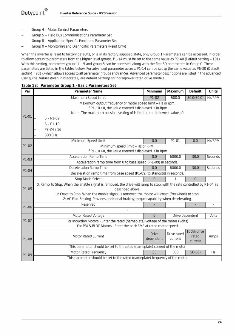
– Group 4 – Motor Control Parameters– Group 5 – Field Bus Communications Parameter Set– Group 8 – Application Specific Functions Parameter Set– Group 0 – Monitoring and Diagnostic Parameters (Read Only)
When the inverter is reset to factory defaults, or is in its factory supplied state, only Group 1 Parameters can be accessed. In order to allow access to parameters from the higher level groups, P1-14 must be set to the same value as P2-40 (Default setting = 101). With this setting, parameter groups 1 – 5 and group 8 can be accessed, along with the first 39 parameters in Group 0. These parameters are listed in the tables below. For advanced parameter access, P1-14 can be set to the same value as P6-30 (Default setting = 201), which allows access to all parameter groups and ranges. Advanced parameter descriptions are listed in the advanced user guide. Values given in brackets () are default settings for horsepower rated drive models.
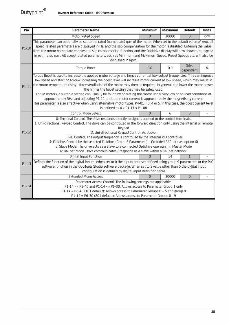
Table 13: Parameter Group 1 - Basic Parameters SetPar Parameter Name Minimum Maximum Default Units
P1-01
Maximum Speed Limit P1-02 500.0 50.0(60.0) Hz/RPMMaximum output frequency or motor speed limit – Hz or rpm.
If P1-10 >0, the value entered / displayed is in RpmNote : The maximum possible setting of is limited to the lowest value of:
– 5 x P1-09– 5 x P1-10– P2-24 / 16– 500.0Hz
P1-02Minimum Speed Limit 0.0 P1-01 0.0 Hz/RPM
Minimum speed limit – Hz or RPM.If P1-10 >0, the value entered / displayed is in Rpm
P1-03Acceleration Ramp Time 0.0 6000.0 30.0 Seconds
Acceleration ramp time from 0 to base speed (P-1-09) in seconds.
P1-04Deceleration Ramp Time 0.0 6000.0 30.0 SedondsDeceleration ramp time from base speed (P1-09) to standstill in seconds.
P1-05
Stop Mode Select 0 1 0 -0: Ramp To Stop. When the enable signal is removed, the drive will ramp to stop, with the rate controlled by P1-04 as
described above.1: Coast to Stop. When the enable signal is removed the motor will coast (freewheel) to stop
2: AC Flux Braking. Provides additional braking torque capability when decelerating.
P1-06Reserved - - -
-
P1-07Motor Rated Voltage 0 Drive dependent Volts
For Induction Motors - Enter the rated (nameplate) voltage of the motor (Volts)For PM & BLDC Motors - Enter the back EMF at rated motor speed
P1-08Motor Rated Current Drive
dependentDrive rated
current
100% drive rated
currentAmps
This parameter should be set to the rated (nameplate) current of the motor
P1-09Motor Rated Frequency 25 500 50(60) Hz
This parameter should be set to the rated (nameplate) frequency of the motor
24
Inverter Reference Guide - IP20 Version
P1-10
Motor Rated Speed 0 30000 0 RPMThis parameter can optionally be set to the rated (nameplate) rpm of the motor. When set to the default value of zero, all
speed related parameters are displayed in Hz, and the slip compensation for the motor is disabled. Entering the value from the motor nameplate enables the slip compensation function, and the Optidrive display will now show motor speed in estimated rpm. All speed related parameters, such as Minimum and Maximum Speed, Preset Speeds etc. will also be
displayed in Rpm.
P1-11
Torque Boost 0.0 0.0 Drive dependent %
Torque Boost is used to increase the applied motor voltage and hence current at low output frequencies. This can improve low speed and starting torque. Increasing the boost level will increase motor current at low speed, which may result in
the motor temperature rising - force ventilation of the motor may then be required. In general, the lower the motor power, the higher the boost setting that may be safely used.
For IM motors, a suitable setting can usually be found by operating the motor under very low or no load conditions at approximately 5Hz, and adjusting P1-11 until the motor current is approximately the magnetising current
This parameter is also effective when using alternative motor types, P4-01 = 3, 4 or 5. In this case, the boost current level is defined as 4 x P1-11 x P1-08
P1-12
Control Mode Select 0 6 0 -0: Terminal Control. The drive responds directly to signals applied to the control terminals.
1: Uni-directional Keypad Control. The drive can be controlled in the forward direction only using the internal or remote Keypad
2: Uni-directional Keypad Control. As above.3: PID Control. The output frequency is controlled by the internal PID controller.
4: Fieldbus Control by the selected Fieldbus (Group 5 Parameters) – Excluded BACnet (see option 6)5: Slave Mode. The drive acts as a Slave to a connected Optidrive operating in Master Mode
6: BACnet Mode. Drive communicates / responds as a slave within a BACnet network.
P1-13
Digital Input Function 0 14 1 -Defines the function of the digital inputs. When set to 0 the inputs are user defined using group 9 parameters or the PLC
software function in the OptiTools Studio software package. When set to a value other than 0 the digital input configuration is defined by digital input definition table
P1-14
Extended Menu Access 0 30000 0 -Parameter Access Control. The following settings are applicable:
P1-14 <> P2-40 and P1-14 <> P6-30: Allows access to Parameter Group 1 onlyP1-14 = P2-40 (101 default): Allows access to Parameter Groups 0 – 5 and group 8
P1-14 = P6-30 (201 default): Allows access to Parameter Groups 0 - 9
Par Parameter Name Minimum Maximum Default Units
25

Inverter Reference Guide - IP20 Version
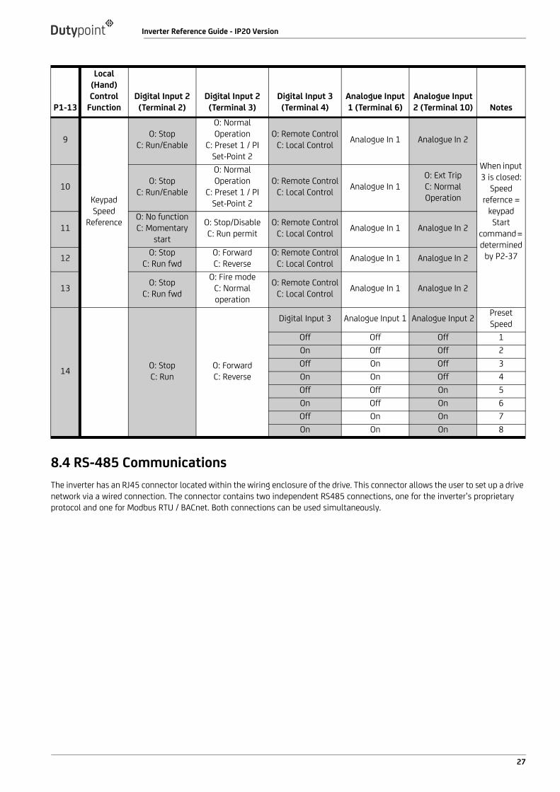
Table 14: Digital Input Configuration Parameter P1-13
P1-13
Local (Hand) Control
FunctionDigital Input 2 (Terminal 2)
Digital Input 2 (Terminal 3)
Digital Input 3 (Terminal 4)
Analogue Input 1 (Terminal 6)
Analogue Input 2 (Terminal 10) Notes
0 N/A All functions user defined or configured through PLC function.
1
Analogue Input 2
O: StopC: Run/Enable
O: Normal Operation
C: Preset 1 / PI Set-Point 2
O: Remote ControlC: Local Control Analogue In 1 Analogue In 2
When input 3 in closed:
Speed reference = Analogue Input 2 Start
command = Input 1.
In PI Mode, Analogue Input 1 must be used for feedback
2O: No functionC: Momentary
Start
O: Stop/DisableC: Run permit
O: Remote ControlC: Local Control Analogue In 1 Analogue In 2
3 O: StopC: Run/Enable
O: ForwardC: Reverse
O: Remote ControlC: Local Control Analogue In 1 Analogue In 2
4O: StopC: Run
/Enable
O: Fire modeC: Normal operation
O: Remote ControlC: Local Control Analogue In 1 Analogue In 2
5
Preset Speeds
O: StopC: Run/Enable
O: Preset speed 1C: Preset speed 2
O: Remote ControlC: Local Control Analogue In 1
O: Ext TripC: Normal Operation
When Input 3 is closed:
Speed reference =
preset speed 1/2
Start command =
input 1
6O: No functionC: Momentary
start
O: Stop/DisableC: Run permit
O: Remote ControlC: Local Control Analogue In 1 O: Preset 1
C: Preset 2
7 O: StopC: Run/Enable
O: ForwardC: Reverse
O: Remote ControlC: Local Control Analogue In 1 O: Preset 1
C: Preset 2
8 O: StopC: Run/Enable
O: Fire modeC: Normal operation
O: Remote ControlC: Local Control Analogue In 1 O: Preset 1
C: Preset 2
26
Inverter Reference Guide - IP20 Version
8.4 RS-485 CommunicationsThe inverter has an RJ45 connector located within the wiring enclosure of the drive. This connector allows the user to set up a drive network via a wired connection. The connector contains two independent RS485 connections, one for the inverter’s proprietary protocol and one for Modbus RTU / BACnet. Both connections can be used simultaneously.
9
Keypad Speed
Reference
O: StopC: Run/Enable
O: Normal Operation
C: Preset 1 / PI Set-Point 2
O: Remote ControlC: Local Control Analogue In 1 Analogue In 2
When input 3 is closed:
Speed refernce =
keypadStart
command = determined
by P2-37
10 O: StopC: Run/Enable
O: Normal Operation
C: Preset 1 / PI Set-Point 2
O: Remote ControlC: Local Control Analogue In 1
O: Ext TripC: Normal Operation
11O: No functionC: Momentary
start
O: Stop/DisableC: Run permit
O: Remote ControlC: Local Control Analogue In 1 Analogue In 2
12 O: StopC: Run fwd
O: ForwardC: Reverse
O: Remote ControlC: Local Control Analogue In 1 Analogue In 2
13 O: StopC: Run fwd
O: Fire modeC: Normal operation
O: Remote ControlC: Local Control Analogue In 1 Analogue In 2
14 O: StopC: Run
O: ForwardC: Reverse
Digital Input 3 Analogue Input 1 Analogue Input 2 Preset Speed
Off Off Off 1On Off Off 2Off On Off 3On On Off 4Off Off On 5On Off On 6Off On On 7On On On 8
P1-13
Local (Hand) Control
FunctionDigital Input 2 (Terminal 2)
Digital Input 2 (Terminal 3)
Digital Input 3 (Terminal 4)
Analogue Input 1 (Terminal 6)
Analogue Input 2 (Terminal 10) Notes
27

Inverter Reference Guide - IP20 Version
Figure 10: RJ45 Connector
WARNING: THIS IS NOT AN ETHERNET CONNECTION
— Do not connect directly to an Ethernet port— When using Modbus RTU or BACnet, ensure that the 0V signal (T3) is also used to avoid comms errors and potentially
damaging common mode voltages
Not usedNot used0V commonRemote keypad/PC connection -Remote keypad/PC connection ++24V remote keypad power supplyRS 485- Modbus RTU / BACnetRS 485+ Modbus RTU / BACnet
28


Dutypoint LimitedShepherd Road
GloucesterGL2 5EL
United Kingdom
T: +44(0)1452 300592W: www.dutypoint.com