operation and maintenance manual - task force · pdf fileoperation and maintenance manual...
TRANSCRIPT

OPERATION andMAINTENANCE MANUAL
PANEL MOUNT
PRO/portionerFOAM INJECTION SYSTEM
Read manual before use. Operation of this system withoutunderstanding the manual and receiving proper training can bedangerous and is a misuse of this equipment.
This manual is intended to familiarize firefighters and maintenancepersonnel with the installation, operation and servicing proceduresassociated with Task Force Tips / KK Product’s PRO/portioner foaminjection system.
This manual should be kept available to all operating andmaintenance personnel.
2800 East Evans Avenue • VALPARAISO • INDIANA • 46383-6940219.462.6161 • 800.348.2686 • FAX 219.464.7155
2
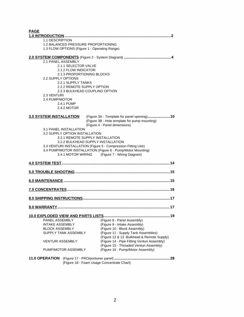
PAGE 1.0 INTRODUCTION .....................................................................................................2
1.1 DESCRIPTION1.2 BALANCED PRESSURE PROPORTIONING1.3 FLOW OPTIONS (Figure 1 - Operating Range)
2.0 SYSTEM COMPONENTS (Figure 2 - System Diagram) .............................................4 2.1 PANEL ASSEMBLY
2.1.1 SELECTOR VALVE2.1.2 FLOW INDICATOR2.1.3 PROPORTIONING BLOCKS
2.2 SUPPLY OPTIONS2.2.1 SUPPLY TANKS2.2.2 REMOTE SUPPLY OPTION2.2.3 BULKHEAD COUPLING OPTION
2.3 VENTURI2.4 PUMP/MOTOR
2.4.1 PUMP2.4.2 MOTOR
3.0 SYSTEM INSTALLATION (Figure 3A - Template for panel opening) .....................10 (Figure 3B - Hole template for pump mounting)(Figure 4 - Panel dimensions)
3.1 PANEL INSTALLATION3.2 SUPPLY OPTION INSTALLATION
3.2.1 REMOTE SUPPLY INSTALLATION3.2.2 BULKHEAD SUPPLY INSTALLATION
3.3 VENTURI INSTALLATION (Figure 5 - Compression Fitting Use)3.4 PUMP/MOTOR INSTALLATION (Figure 6 - Pump/Motor Mounting)
3.4.1 MOTOR WIRING (Figure 7 - Wiring Diagram)
4.0 SYSTEM TEST.......................................................................................................14
5.0 TROUBLE SHOOTING ..........................................................................................15
6.0 MAINTENANCE .....................................................................................................15
7.0 CONCENTRATES..................................................................................................16
8.0 SHIPPING INSTRUCTIONS...................................................................................17
9.0 WARRANTY...........................................................................................................17
10.0 EXPLODED VIEW AND PARTS LISTS...............................................................19 PANEL ASSEMBLY (Figure 8 - Panel Assembly)INTAKE ASSEMBLY (Figure 9 - Intake Assembly)BLOCK ASSEMBLY (Figure 10 - Block Assembly)SUPPLY TANK ASSEMBLY (Figure 11 - Supply Tank Assemblies)
(Figure 12 & 13 -Bulkhead & Remote Supply)VENTURI ASSEMBLY (Figure 14 - Pipe Fitting Venturi Assembly)
(Figure 15 - Threaded Venturi Assembly)PUMP/MOTOR ASSEMBLY (Figure 16 - Pump/Motor Assembly)
11.0 OPERATION (Figure 17 - PRO/portioner panel) .....................................................28(Figure 18 - Foam Usage Concentrate Chart)

3
KK PRODUCTS PANEL MOUNT PRO/portioner OPERATIONS MANUAL
1.0 INTRODUCTION
Welcome to the growing number of users of the PRO/portioner injection system. KK Products has beendesigning and manufacturing quality fire fighting and suppression equipment since 1969. The KK Productsline of single, dual, and selectable gallonage fog nozzles, and foam application and injection equipment isrepresented by over a hundred dealers worldwide. Please take a moment and fill out the enclosedWARRANTY card, and return it within ten days of placing the unit in service. This validates the unit’swarranty and will keep you informed of new products and services.
1.1 DESCRIPTION
The PRO/portioner is a discharge side, concentrate injection system. Designed to inject liquid concentratesinto a water flow at a user selectable concentrate ratio from 0.1% to 1%, this system offers dependabilityand ease of operation in rugged environments. The desired concentrate ratio is maintained at all flow ratesup to the maximum flow capacity of the concentrate pump. Once selected, the concentrate ratio willautomatically be injected into the water stream and will not be affected by variations in hose length,pressure, or elevation. With a maximum concentrate flow of 1.25 GPM, the PRO/portioner will operate easilyat 1% ratios up to 125 GPM, and at 0.5% ratios up to 250 GPM. Designed especially for use with Class Afoaming agents, 1% AFFF, and wetting agent concentrates, the PRO/portioner operates on a balancedpressure concept.
Do not use 3 to 6% class B foams in the PRO/portioner. The use of 3 to 6%Class B foams will result in weak and ineffective foam. Maximum mix ratio, ofthis PRO/portioner is 1%.
The PRO/portioner is designed for Class A and Class B AFFF concentrates only. Do not attempt to use any3 or 6% concentrates in the PRO/portioner, or Class A foams not meeting USDA Forest Service “InterimRequirements for Foam for Wildland Fires, Aircraft or Ground Application” or NFPA 298 “Foam Chemicalsfor Wildland Fire Control”.
1.2 BALANCED PRESSURE PROPORTIONING
The PRO/portioner is similar in concept to the carburetor on a gasoline engine. In a carburetor the air to fuelratio remains constant as the amount of air through the carburetor changes. As the engine speeds up, theamount of air passing through the carburetor increases and more gasoline is injected into the air stream tomaintain a constant percentage. A carburetor can make the mixture leaner or richer by adjusting the jets.The fuel pump maintains fuel pressure while the carburetor does the proportioning.
The pump on the PRO/portioner supplies the pressure to inject the concentrate into the water stream. Theproportioning block, like the carburetor on an engine, maintains proper percentage. The pump is driven by a12 VDC electric motor.

4
1.3 FLOW OPTIONS
The panel mount PRO/portioner is available in two flow ranges. The LOW FLOW model has a flow range of10 to 125 GPM at any concentration between 0.1% and 1%. The LOW FLOW model gives greater accuracyfor mop-up and booster line flows.
The HIGH FLOW model has a flow range of 25 to 125 GPM at any concentration between 0.1% and 1%,and may go to 250 GPM at lower percentages. At flows between 125 and 250 GPM, the maximumconcentration is limited by the output of the concentrate pump which is 1.25 GPM. At any flow below 250GPM, it is always possible to get at least 0.5% concentration. The concentrations possible at any flow isshown in Figure 1. In each case the venturi insert and concentrate adjustment knob are designed to worktogether. To avoid mix-up, the knob caps for the LOW FLOW range PRO/portioners are white and the HIGHFLOW versions are black.
Maximum operating pressure is 300 psi. Over pressurizing system may result inloss of foam flow and can damage components.
FIGURE 1 PANEL MOUNT PRO/PORTIONER OPERATING RANGE

5
2.0 SYSTEM COMPONENTS
Figure 2 shows the system components and their relation to each other. Each of the components isdescribed in the following sections. A system diagram on a 4 by 6 inch aluminum plate (KK part #G561) isprovided for mounting on the apparatus.
FIGURE 2 PANEL MOUNT PRO/PORTIONER SYSTEM DIAGRAM
2.1 PANEL ASSEMBLY
The panel assembly consists of the selector valve, flow indicator and the proportioning blocks.
2.1.1 SELECTOR VALVEOne or two supply tanks can be used with the system. The selector valve is rotated to select a tankas indicated on the engraved panel. There is a spring loaded detent at each of the three positions.Turning this knob to either tank A or B also activates an electrical switch that turns on theconcentrate pump. In the off position each tank is completely shut off from the rest of the system.

6
2.1.2 FLOW INDICATORThe flow indicator indicates concentrate flow from the selected tank to the water stream. The silverfloat raises as flow increases. It is also used to indicate when the pump has primed. Due to thenature of foam concentrates, the indicator will read higher in colder temperatures.
2.1.3 PROPORTIONING BLOCKSThe PRO/portioner blocks process all system inputs to produce the desired concentrate ratio. Thereare two control knobs on the blocks. The percent knob controls the amount of concentrate added tothe water stream. It is infinitely variable between the extremes of .1% to 1%. The mode knob placesthe unit in one of three operational modes: prime, foam or flush. In the prime mode the outlet to thepump goes directly to the vent tube allowing air to be expelled from the system. In the foam positionconcentrate is metered into the water stream at the desired concentration. In the flush position waterfrom the water stream circulates through the concentrate pump and proportioning blocks, flushingconcentrate out of the system through the vent tube.
2.2 SUPPLY OPTIONS
2.2.1 SUPPLY TANKSThe supply tank(s) holds foam concentrate ready for use. An optional second tank can be used formore capacity or for a different type of foam concentrate. An 8-gallon (part# G9000T08), 12-gallon(part# G9000T12) or 20-gallon (part# G9000T20) tank kit is available through KK Products. Drainvalve and fittings are provided. Also supplied with each tank is a filtered funnel for refilling. The tanklid contains a filter, has a 4" diameter opening and is pressure/vacuum vented.
2.2.2 REMOTE SUPPLY OPTIONThe remote supply (G9000R) can be used in conjunction with any brand of tank compatible withfoam concentrate. This supply option contains the hose, hose fittings, and filter necessary forconnecting a supply tank to the panel mount. Tank must be both pressure and vacuum vented tohelp keep concentrate volatiles from evaporating and to not create vacuum as concentrate is used.
2.2.3 BULKHEAD COUPLING OPTIONThe bulkhead supply (G9P00B) allows foam to be supplied from a bucket or alternate source notmounted on the vehicle. A bulkhead coupling with a quick connect nipple can be mounted onto thetruck panel and attached to a hose which leads behind the panel, through a filter, to the tank selectorvalve on the panel mount. A stainless steel wand with a quick connect socket and valve is providedand can be quickly attached to the quick connect nipple to supply the unit with foam concentrate.

7
2.3 VENTURI
The venturi serves two functions. It senses the water flow passing through it and also provides a place forthe concentrate to be injected into the water stream. The venturi has less pressure drop across it than aneductor as seen in the graph below. It is the pump and motor that do the actual work of injecting theconcentrate into the water. The venturi is available with standard hose threads, grooves for Victaulic®
couplings, pipe threads or flanged. See Figures 14 and 15 for the types and sizes available.
NOTE: A venturi is a restriction in the water flow area. Large increases in venturi inlet pressure arerequired to increase flow beyond the venturi’s rated range.
PRESSURE LOSS Eductor vs Venturi
95 GPM Eductor
Low Flow Venturi
High Flow Venturi
60
55
50
45
40
35
30
25
20
15
10
5
00 25 50 75 100 125 150 175 200 225 250
2.4 PUMP/MOTOR
2.4.1 PUMPThe PRO/portioner uses a positive displacement three piston pump to minimize pressure pulsations.The pump has a capacity of 1.25 GPM. The pump is capable of pressures far greater than thoseencountered on the fire ground. No relief valve is necessary because the motor does not haveenough power to damage the pump.
The pump is internally lubricated and may be run without concentrate or water for a prolonged periodwithout damage.
2.4.2 MOTORThe electric motor is a totally enclosed 12 VDC, 1/3 horsepower electric motor, and is designed forsystem pressures up to 300 PSI. At 300 PSI system pressure, the motor is at full load and will draw27 AMPS of current. At lower pressures the electric current will be proportionately less. The motor isturned on whenever the selector knob is in the tank A or tank B position. A flashing green indicatorlight will be on whenever the motor is running.

8
TEMPLATE FOR PANEL OPENINGMinimum Required Clearance Behind Panel For Installation Is 8-1/2"
FIGURE 3A TEMPLATE FOR PANEL OPENING
CUT-OUT THIS AREA�2Q�2XWVLGH�2I�/LQH)
�������+HLJKW;
�������:LGWK
9
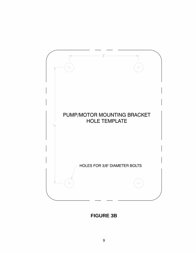
FIGURE 3B

10

11
3.0 SYSTEM INSTALLATION
3.1 PANEL INSTALLATION
Determine panel location for ease of operation and space constraints, allowing room for all hoses andfittings. Refer to Figure 4 for panel dimensions (also see template Figure 3A). Cut rectangular opening atdesired location 6-3/4" wide by 7-3/4" high. Place panel assembly into opening and secure with the 3clamps located at the two lower corners and top center. Press 1/4" vinyl tube (vent line) onto barb fitting onbottom of blocks and route to appropriate area to allow dumping of some fluid to the ground. Peel protective film from flow indicator label. Place flow indicator label behind window. Insert window in cutout at flow indicator. Fasten engraved face plate to front of unit with the four #6-32 screws provided.NOTE: The panel of the PRO/portioner needs to be mounted to a conductive grounded surface or a #16 AWG jumper wire must be used between the panel grounding lug (where light and switch ground wire attach) and a suitable ground.
3.2 SUPPLY OPTION INSTALLATION
Foam concentrate supply plumbing should use only brass or plastic components that are compatible withfoam concentrates.
Debris in the foam can cause the system to become inoperative. Theconcentrate tank must have a filter (maximum opening size of .016 inch x 12 in²minimum filter area) affixed to the tank entrance or in the concentrate hosegoing to the proportioning unit. Clean the filter regularly to avoid blockage.
3.2.1 SUPPLY TANK INSTALLATIONFor best results mount the tank above the height of the panel and concentrate pump (the lower thetank, the longer system will take to prime). Use 3/4" I.D. hose with barb fittings and hose clamps toconnect the tank to selector valve on panel. Secure hose as required to prevent damage from snags,excessive heat and abrasions. If only one tank is used, install a tee in the hose line to feed both supply inlets on the selector valve. This will assure that foam will be supplied if valve is inadvertently turned to an otherwise unused position. A suitable barbed tee fitting is available from KK Products as part number VFMT6BX6BX6B. Install drains in tank hoses as desired. Thefittings and valves are included in the 8-gallon tank kit (part #G9000T08) the 12-gallon tank kit (part#G9000T12) or the 20-gallon tank kit (part# G9000T20) as loose parts to be assembled to suit yourparticular installation. Teflon tape must be used to ensure a proper seal. Mounting instructions fromthe tank manufacturer are shipped inside the tank. NOTE: Tank bulkhead fitting must not be tightened more than 1/2 turn past hand tight.
3.2.2 BULKHEAD SUPPLY INSTALLATIONDetermine location for ease of hook-up and space constraints, allowing room for hose and filterbehind location. Cut a 1/2" diameter hole to mount bulkhead fitting. Mount the bulkhead couplingthrough the opening and secure with the lock washer and nut provided. The filter can be threadeddirectly into the bulkhead coupling. Make sure filter is installed bowl side down. Use 3/4" I.D. hosewith barb fittings and hose clamps to connect filter to the selector valve on the panel. Secure hoseas required to prevent damage from snags, excessive heat and abrasions. The quick connect wandcan be stored in a compartment or attached and secured to the panel.

12
3.3 VENTURI INSTALLATION
The Victaulic® venturis are available in standard 2.0" and 2.5" sizes. Standard Victaulic® couplings, style 75or 77, clamp into the grooves on the venturi. Victaulic® reducing couplings may be used for installation withother pipe sizes. The water MUST flow in the direction of the arrow on the venturis. The venturi should beinstalled between the outlet of the water pump and the discharge valve. A one-way check valve (wafer-typeor equivalent) may be installed ahead of the venturi connection to prevent possible back flow of foam agentsinto tanks or water source. Turbulent water entering the venturi from partially gated valves can causeinaccurate proportioning. There are threaded holes for tapered pipe fittings in the venturi. Orient venturi sothat the tube fittings are on its upper half (this helps keep dirt from entering system). The maximumallowable distance between the venturi and the proportioning block is 6 feet. Tubing may be cut shorter ifdesired. Install 1/2" O.D. nylon tubing and 3/8" O.D. nylon tubing between venturi and the proportioningblocks as shown in Figure 2. Use the brass compression fittings provided. NOTE: The brass compression fitting already has thread sealant applied to it, so pipe dope or Teflon tape is unnecessary. Secure hose as required to prevent damage from snags, excessive heat and abrasions. Figure 5 shows the proper use of these compression fittings.
3.4 PUMP/MOTOR INSTALLATION
The pump/motor assembly is installed by means of a mounting bracket. It can be mounted up to six feetfrom the panel and needs a well ventilated environment. Maximum operating temperature of the pump andmotor housing is 180 degrees F. The unit must be able to dissipate its heat to avoid overheating. Avoidlocations that expose the unit to dirt and spray from truck wheels. Assure access to the oil drain plug and fillplug. The bracket has four holes for 3/8" bolts, on a 3 X 5" bolt hole pattern. See Figure 6 for mountingconfiguration and dimensions and Figure 3B for mounting hole template. The unit is shipped with the bracketon the left side of the unit. The bracket may be changed to the bottom position by removing the four boltsholding the pump and motor together, reorienting the bracket and reinstalling the bolts. Install 3/4" I.D. blackhose and 1/2" O.D. nylon tubing between fittings on pump and PRO/portioner blocks as shown in Figures 2and 4. Hose may be shortened if desired. Secure hose runs as required to prevent damage from snags and

13
abrasions. Drains may be installed in the pump lines as desired. THE PUMP ITSELF MUST REMAINUPRIGHT WITH THE MOTOR SHAFT HORIZONTAL FOR PROPER LUBRICATION (OIL FILLER CAPON TOP). See figure 6 for proper pump orientation.
The electric motor and other components are ignition sources. The PRO/portioner should beoperated only in areas where there is adequate ventilation and no hazard of flammable vaporbuildup.
FIGURE 6 PUMP/MOTOR HOUSING
3.4.1 MOTOR WIRINGRefer to Figure 7 for motor wiring. Good mechanical connections on the wires are absolutelynecessary and should be checked periodically. Poor electrical connections can cause power loss tothe PRO/portioner and a fire hazard. Disconnect power before installing or servicing the electricalcomponents. Most of the wiring has been factory installed. The remaining wires needing hookup are:

14
a) CORD BETWEEN PANEL AND MOTOR: The #16-2 cord provided connects the motor to the panel. Allconnectors are precrimped. Starting at the panel, the white wire goes to the switch and the black wire goesto the light. Use the cable clamp on the back of the flow indicator for cord mounting. Remove the motorcover (two acorn nuts) and pass the other end of the cord through the large wire fitting on the motor coverwith the white wire attaching at terminal #85 of the relay and the black wire to terminal #87. Tighten the wireretainer. NOTE: Motor needs to be mounted to a conductive grounded surface or a #10 AWG jumper wire must be used between a mounting bracket bolt and a suitable ground. Ground connection must be capable of carrying 30 amps with minimal voltage drop.
b) POWER TO RELAY: The red #10 AWG wire with 30 AMP circuit breaker supplies power to the motor’srelay. Pass one end of this red wire through the small wire fitting on motor cover and attach to terminal #30on the relay. Tighten wire firmly. Reinstall motor cover. For circuit protection a 30 AMP breaker is providedand must be installed as close as possible to the power source. The 30 AMP circuit breaker will trip if themotor is overloaded or overheated. When the circuit breaker trips, the green light will go out. The 30 AMPcircuit breaker is internally sealed. It is a type I cycling breaker which continuously resets itself until theoverload is corrected. The other end is connected to the positive side of a 12 volt power supply capable ofsafely maintaining a 30 AMP load. Use #10 wire. For runs over 30 feet, use #8 or heavier wire. NOTE: Relay voltage is 15 VDC max. / 9.5 VDC min.
FIGURE 7 WIRING DIAGRAM
15
Use grommets whenever wire passes through holes and secure to prevent damage due to snags,abrasions, etc.
After all wiring has been installed, test system by turning selector knob on panel from OFF to A or B position.If system is working properly, the flashing green light and motor should come on. If not, refer to the trouble-shooting section below.
PROBLEM CHECK
Motor does not run - Reed panel switch and white control wire - Ground at panel and/or motor
Circuit breaker trips - For shorts to ground - Wires between motor and panel for reversed lead
Clicking relay - For low voltage at relay (if < 9.5 VDC, check power circuit) - For poor electrical contact on control panel
Motor runs in Off position - Reed panel switch or white control wire for shorts to ground.
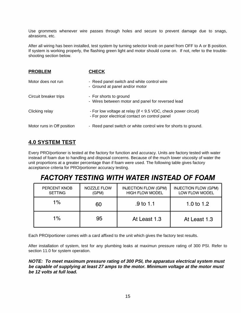
4.0 SYSTEM TEST
Every PRO/portioner is tested at the factory for function and accuracy. Units are factory tested with waterinstead of foam due to handling and disposal concerns. Because of the much lower viscosity of water theunit proportions at a greater percentage than if foam were used. The following table gives factoryacceptance criteria for PRO/portioner accuracy testing.
Each PRO/portioner comes with a card affixed to the unit which gives the factory test results.
After installation of system, test for any plumbing leaks at maximun pressure rating of 300 PSI. Refer tosection 11.0 for system operation.
NOTE: To meet maximum pressure rating of 300 PSI, the apparatus electrical system mustbe capable of supplying at least 27 amps to the motor. Minimum voltage at the motor mustbe 12 volts at full load.

16
5.0 TROUBLE SHOOTING
SYMPTOM CAUSE REMEDY
No foam flow Foam tank empty Refill tank and reprime PRO/portionerindicated
Air in lines Check for and correct any leaks leading to pump inlet
Pump is off Check electrical system
Debris in concentrate pump Clean pump check valves
Air vent plugged on Unplug or open vent concentrate tank
Pump mounted sideways Reorient pump (see figure 5) andreprime pump hydraulic cells(see pump manual service section)
Weak foam mix Debris caught in Remove & clean percentage knob percentage knob
Thick concentrate, cold Change to thinner brand
Internal deposits of old Fill concentrate tank with clean dried concentrate water and flush unit thoroughly
Motor cycles on/off System pressure too high Lower engine pressure, Circuit breaker tripping use larger hose or shorten lay
Excessive heat, Improve ventilation Circuit breaker tripping
Concentrate Debris in concentrate Clean pump check valvesflows with pumpnozzle shut off
6.0 MAINTENANCE
Any alteration to PRO/portioner or its markings constitutes a misuse ofthis product and could diminish safety.
The oil level should be 3/4" from the top of the fill port - just below the small holes on the fill plug’s dipstick.Use SAE 5W30 non detergent oil. Change the oil after every 100 hours or three months of operation,whichever comes first. Regular oil changes will help insure a long and trouble-free service life.
No maintenance is required on the motor, but for long life it should be run in a well ventilated areaand be kept as dry as possible.
17
If the unit will not be used for more than 60 days, the following procedures are recommended. Drain the tankand rinse with clean water, leaving about 5 gallons of clean water in the tank. Set up the PRO/portioner asyou would for fire-fighting and pressurize the water line. Run the unit for a few minutes drawing water,instead of concentrate, into the PRO/portioner. Rotate both control knobs back and forth a few times whilethe unit is running. Finally, turn the Mode Selection knob to FLUSH and run for one minute. After the unit isshut down, perform all other required maintenance listed above. Clean the PRO/portioner with a damp cloth.If the unit must be stored where the temperature will be below freezing, prime the unit with a 50/50 mixtureof water and automotive antifreeze (glycol based).
The PRO/portioner can be serviced using common hand tools such as allen wrenches, sockets, adjustableor open-end wrenches, screw drivers, and pliers.
When ordering parts, always specify the serial number found on the PRO/portioner at the bottom of theengraved panel. Be sure to use the complete order number and description, as printed in the parts list.
Threaded joints have been secured using LOCTITE brand thread locking adhesive #271. Disassembly mayrequire considerable torque to break the adhesive. If the fastener cannot be broken loose, heat the threadsto 450 degrees F with a propane or oxyacetylene torch to break the bond. The application of excessive heatmay damage adjacent seals and components. Threaded parts must be reassembled using LocTite #271 orequivalent. Small containers of LocTite are available from KK Products, part number V5010, LocTite MiniDispenser.
7.0 CONCENTRATES
Improper use of foam is dangerous to personnel and the environment.Follow foam concentrate manufacture’s instructions and fire servicetraining to avoid such things as:
- Using wrong type of foam on a fire. i.e. Class A foam on a Class B fire.- Mishandling of concentrates, some of which are flammable.- Causing environmental damage.
Do not use 3 to 6% class B foams in the PRO/portioner. The use of 3 to6% foams will result in weak and ineffective foam. Maximum mix ratio ofthis PRO/portioner is 1%.
The PRO/portioner is designed for Class A and Class B AFFF concentrates only. Do not attempt to use any3 or 6% concentrates in the PRO/portioner, or Class A foams not meeting USDA Forest Service “InterimRequirements for Foam for Wildland Fires, Aircraft or Ground Application” or NFPA 298 “Foam Chemicalsfor Wildland Fire Control”.
Do not mix different types of concentrates. When Class A and Class B foams are mixed, the mixture canbecome very thick or solidify. We recommend that foam tanks be thoroughly rinsed when switching to adifferent type of foam. In systems with two or more foam tanks that contain different types of foam, werecommend that the PRO/portioner be flushed prior to switching to a different foam tank to preventconcentrate mixing in the PRO/portioner. For more information, contact your foam supplier.
The chemical makeup of most fire-fighting concentrates is a trade secret. The user should obtain completeliterature and a MATERIAL SAFETY DATA SHEET for each concentrate used. The recommendations andcautions of each manufacturer should be closely followed.

18
Some concentrates can attack metals, rubber and plastic. KK Products has tried to use materials in thePRO/portioner that resist chemical attack, but cannot predict all the effects of concentrates on thePRO/portioner’s components over time and in different environments. Therefore, it is not possible for KKProducts to warrant the components of the PRO/portioner against chemical attack. The best way to prolongthe life of your PRO/portioner is to limit its long term exposure to concentrates. While the water line is stillpressurized, turn the mode selection knob to the FLUSH position and run the PRO/portioner for at least oneminute to wash the concentrate from the system.
Viscosity is a fluid’s resistance to flow. The higher the viscosity, the thicker the fluid. At room temperaturemost common concentrates have roughly the same viscosity. However, at lower temperatures, some become extremely viscous and will resist flowing, and the PRO/portioner will not maintain the correctconcentrate percentage. When operating in cold climates, choose a brand of concentrate with a lowviscosity, or keep the concentrate in a warm place until it is used. Maximum concentrate viscosity is 120 CPS (centipoise).
Figure 18 at the end of this manual gives foam concentrate usage for various water flows and percentages.
8.0 SHIPPING INSTRUCTIONS
The PRO/portioner may be shipped by United Parcel Service by following these easy steps:
1) Select a very strong box and pack around PRO/portioner securely to prevent motion.
2) Pack pump upright and mark box ’THIS SIDE UP’ to prevent pump oil from leaking out.
3) If shipping to KK Products, please include your name, phone and address, and pertinent instructions.
4) Shipping insurance may be purchased from UPS for a modest fee.
9.0 WARRANTY
Task Force Tips, 2800 East Evans Avenue, Valparaiso, Indiana 46383-6940 warrants to the originalpurchaser of the Panel Mount (“equipment”), and to anyone to whom it is transferred, that the equipmentshall be free from defects in material and workmanship during the two (2) year period from the date ofpurchase.
Task Force Tips obligation under this warranty is specifically limited to replacing or repairing the equipment(or its parts) which are shown by Task Force Tips examination to be in a defective condition attributable toTask Force Tips. To qualify for this limited warranty, the claimant must return the equipment to Task ForceTips, at 2800 East Evans Avenue, Valparaiso, Indiana 46383-6940, within a reasonable time after discoveryof the defect. Task Force Tips will examine the equipment. If Task Force Tips determines that there is adefect attributable to it, it will correct the problem within a reasonable time. If the equipment is covered bythis limited warranty, Task Force Tips will assume the expenses of repair.
If any defect attributable to Task Force Tips under this limited warranty cannot be reasonably cured by repairor replacement, Task Force Tips may elect to refund the purchase price of the equipment, less reasonabledepreciation, in complete discharge of its obligations under this limited warranty. If Task Force Tips makesthis election, claimant shall return the equipment to Task Force Tips free and clear of any liens andencumbrances.

19
This is a limited warranty. The original purchaser of the equipment, any person to whom it is transferred, andany person who is an intended or unintended beneficiary of the equipment, shall not be entitled to recoverfrom Task Force Tips any consequential or incidental damages for injury to person and/or property resultingfrom any defective equipment manufactured or assembled by Task Force Tips. It is agreed and understoodthat the price stated for the equipment is in part consideration for limiting Task Force Tips liability. Somestates do not allow the exclusion or limitation of incidental or consequential damages, so the above may notapply to you.
Task Force Tips shall have no obligation under this limited warranty if the equipment is, or has been,misused or neglected (including failure to provide reasonable maintenance) or if there have been accidentsto the equipment or if it has been repaired or altered by someone else.
THIS IS A LIMITED EXPRESS WARRANTY ONLY. TASK FORCE TIPS EXPRESSLY DISCLAIMS WITHRESPECT TO THE EQUIPMENT ALL IMPLIED WARRANTIES OF MERCHANTABILITY AND ALLIMPLIED WARRANTIES OF FITNESS FOR A PARTICULAR PURPOSE. THERE IS NO WARRANTY OFANY NATURE MADE BY TASK FORCE TIPS BEYOND THAT STATED IN THE DOCUMENT.
Excluded from this warranty are abuse, neglect, and chemical attack, as well as damage done by usersperforming maintenance. In addition, damage or malfunction caused by users adaptation to purposes notapproved by Task Force Tips shall not be warranted. If service is necessary, please contact the factorybefore shipping the unit. Some problems can be solved over the phone. Make sure the PRO/portioner isworking properly before attempting to extinguish a fire. If you have any problems or questions, pleasecall Task Force Tips, toll free, at 1-800-348-2686.
Task Force Tips, Inc2800 East Evans AvenueValparaiso, IN 46383-6940 • 800.348.2686219.462.6161 • Fax 219.464.7155http://www.tft.com
20
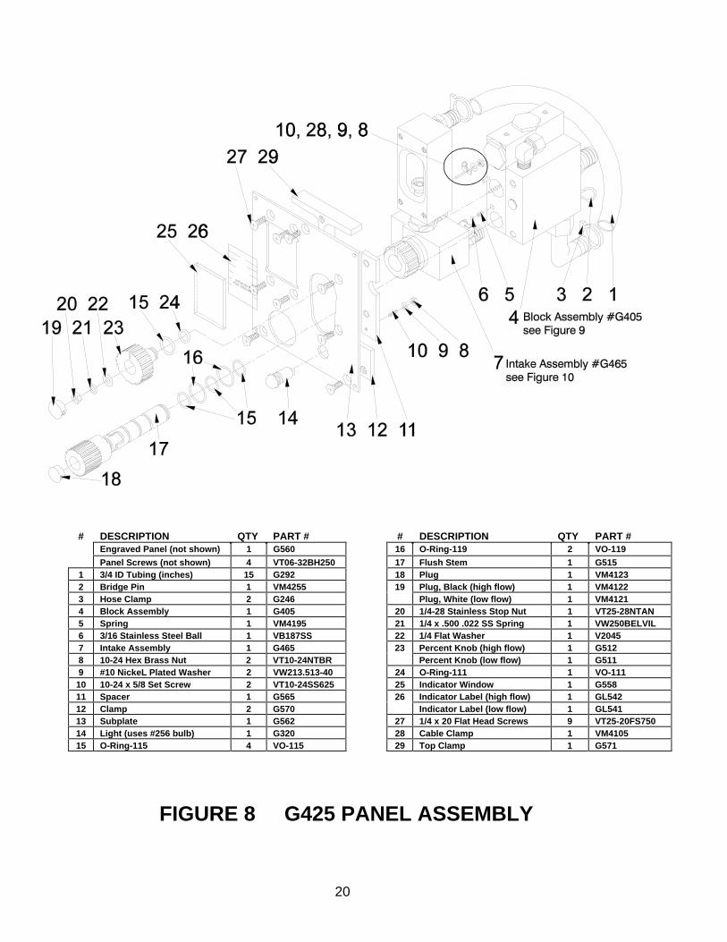
FIGURE 8 G425 PANEL ASSEMBLY
# DESCRIPTION QTY PART # # DESCRIPTION QTY PART #Engraved Panel (not shown) 1 G560 16 O-Ring-119 2 VO-119
Panel Screws (not shown) 4 VT06-32BH250 17 Flush Stem 1 G5151 3/4 ID Tubing (inches) 15 G292 18 Plug 1 VM41232 Bridge Pin 1 VM4255 19 Plug, Black (high flow) 1 VM41223 Hose Clamp 2 G246 Plug, White (low flow) 1 VM41214 Block Assembly 1 G405 20 1/4-28 Stainless Stop Nut 1 VT25-28NTAN5 Spring 1 VM4195 21 1/4 x .500 .022 SS Spring 1 VW250BELVIL6 3/16 Stainless Steel Ball 1 VB187SS 22 1/4 Flat Washer 1 V20457 Intake Assembly 1 G465 23 Percent Knob (high flow) 1 G5128 10-24 Hex Brass Nut 2 VT10-24NTBR Percent Knob (low flow) 1 G5119 #10 NickeL Plated Washer 2 VW213.513-40 24 O-Ring-111 1 VO-111
10 10-24 x 5/8 Set Screw 2 VT10-24SS625 25 Indicator Window 1 G55811 Spacer 1 G565 26 Indicator Label (high flow) 1 GL54212 Clamp 2 G570 Indicator Label (low flow) 1 GL54113 Subplate 1 G562 27 1/4 x 20 Flat Head Screws 9 VT25-20FS75014 Light (uses #256 bulb) 1 G320 28 Cable Clamp 1 VM410515 O-Ring-115 4 VO-115 29 Top Clamp 1 G571

21
1234
5
657894
1
1110
1918
1716
121314
15
FIGURE 9 G465 INTAKE ASSEMBLY
# DESCRIPTION QTY PART#1 MALE BARBED FITTING 3 VFNN6BX4M2 METER BODY 1 G5403 1/4-20 X 3/8 SOCKET SET 1 VT25-20SS3754 3/16 SS BALL 302 SS 2 VB187SS5 O-RING-211 2 V0-2116 METER GLASS 1 G5557 FLOAT 1 G5508 DETENT SCREW 1 D2909 SPRING 1 VM4195
10 4-40 X 3/8 PAN HEAD 2 VT04-40PH37511 PANEL SWITCH, REED 1 VM414312 METER TUBE 1 G54513 O-RING-016 1 VO-01614 3/8-24 PIPE PLUG 1 VFSP3M15 SELECTOR BODY 1 G52016 SELECTOR SLEEVE 1 G53017 MAGNET 1 VM415218 SELECTOR VALVE 1 G41419 PLUG 1 VM4122

22
FIGURE 10 G405 BLOCK ASSEMBLY
# DESCRIPTION QTY PART# # DESCRIPTION QTY PART#1 TOP CAP 2 G190 19 1/8 NPT X 1/4 ID CONN 1 VFNN2BX1M2 O-RING-119 3 VO-119 20 1/2 NPT X 3/4 ID ELBOW 1 VFLL6BX4M3 DISTRIBUTOR ROD 1 G194 21 CHECK VALVE SEAT 1 G5054 PULSATION PRISM 1 G196 22 BALL RETAINER 1 G5075 1/4-28 X 2.5 STUD 1 VT25-28SD2.5 23 O-RING-016 1 VO-0166 5/32 X 7/8 HDP SPIROL SET 1 V1900 24 5/8 POLYPROPYLENE BALL 1 VB625PP7 THICK BLOCK 1 G110 25 3/4 BARBED FITTING 1 VFNN6BX4M8 LOCATOR PIN 2 G177 26 VS269NTA-8-6 MALE ELBOW 2 VFLL4PX3M9 DIAPHRAGM DISC 1 G162 27 1/4 PIPE EXTENSION 1 VFAA2FX2M
10 O-RING-007 1 VO-007 28 VS269NTA-6-4 MALE ELBOW 1 VFLL3PX2M11 KNUCKLE 1 G163 29 CHECK RING 1 G19812 DIAPHRAGM 1 G125 30 1/2 POLYPROPYLENE BALL 1 VB500PE13 CONTROL VALVE 1 G160 31 5/16-18 X .750 SOCKET SET 1 VT31-18SS75014 10-24 X 3/8 FLAT SOCKET 3 VT10-24FS375 32 5/16-18 X 1/4 SOCKET SET 1 VT31-18SS25015 DIAPHRAGM SPRING 1 VM5015 33 5/16-18 X 1-1/2 SHCS 4 VT31-18SH1.516 VALVE SEAT 1 G161 34 FILTER NUT 1 G19217 3/8-24 PIPE PLUG 1 VFSP3M 35 FILTER WASHER 1 MS73018 PANEL BLOCK 1 G510

23
FIGURE 11 SUPPLY TANK ASSEMBLIES
# DESCRIPTION QTY PART#1 FILTER FUNNEL 1 G2142 TANK LID SUB-ASSEMBLY 1 G4553 TANK, 12 GALLON (shown) 1 G212
TANK, 8 GALLON 1 G200TANK, 20 GALLON 1 G220
4 3/4 - 1/2 BUSHING 1 VFHB6MX4F5 1/2 X 1/2 HEX NIPPLE 2 VFHN4MX4M6 1/2" NPT PIPE T 1 VFFT4FX4FX4F7 1/2 x 1/2 FNPT VALVE 1 G2538 3/4 BARB X 1/2 MNPT 2 VFNN6BX4M9 SS HOSE CLAMP 4 G246
10 3/4 ID VARDEX TUBING (inches) 108 G29211 BULKHEAD FITTING 1 G255

24
FIGURE 12G9P00B BULKHEAD SUPPLY SYSTEM
# DESCRIPTION QTY PART#1 PROPORTIONER WAND 1 G2052 WAND LABEL 1 GL0703 SS HOSE CLAMP 1.0 DIA 4 G2464 3/4" ID VARDEX HOSE (2) 84" G2925 1/2" X 1/2" FNPT VALVE 1 G2536 1/2" X 1/2" HEX NIPPLE 2 VFHN4MX4M7 1/2" QC SOCKET X 1/2" FNPT 1 VFAA4QX4F8 1/2" X 1/2" QC NIPPLE 1 VFNN4QX4M9 QC CAP 1 G264
10 1/2 NPY BULKHEAD COUPLING 1 VFBC4FX4F11 3/4" BARB X 1/2" MNPT 1 VFHN6BX4M12 QC PLUG 1 G26313 3/4” X 1/2” HEX NIPPLE 1 VFHN6MX4M14 FILTER HEAD 1 G27515 FILTER BOWL 1 G27616 FILTER SCREEN 1 G27717 3/4” BARB X 3/4” MNPT 1 VFHN6MX6B

25
FIGURE 13G9000R REMOTE SUPPLY SYSTEM
# DESCRIPTION QTY PART#1 3/4" BARB X 3/4" MNPT 2 VFHN6MX6B2 FILTER HEAD 1 G2753 FILTER BOWL 1 G2764 FILTER SCREEN 1 G2775 SS HOSE CLAMP 4 G2466 3/4" ID VARDEX HOSE 84" G292

26
FIG 14 PIPE FITTING VENTURIS
# DESCRIPTION QTY PART#1 2.5 VICTAULIC® VENTURI (ALUM) 1 G1282 2.0 VICTAULIC® VENTURI (ALUM) 1 G1293 2.5 NPT VENTURI (BRONZE) 1 G5854 2" NPT VENTURI 1 G5805 FLANGED VENTURI (BRONZE) 1 G5886 1/4 PIPE EXTENSION 1 VFAA2FX2M7 1/4 ELBOW FITTING 1 VFLL3PX2M
1/4 STRAIGHT FITTING 1 VFAA3PX2M8 3/8 ELBOW FITTING 1 VFLL4PX3M
3/8 STRAIGHT FITTING 1 VFAA4PX3M9 1/2 OD NYLON TUBING (inches) 72 VM4325
10 3/8 OD NYLON TUBING (inches) 72 VM433011 O-RING-124 1 VO-12412 O-RING-126 1 VO-12613 LOW FLOW VENTURI INSERT (ALUM) 1 G53114 HEART VALVE 1 G14115 HIGH FLOW VENTURI INSERT (ALUM) 1 G13217 BACK RING 1 G12318 LOW FLOW VENTURI INSERT (BRONZE) 1 G531-64219 HIGH FLOW VENTURI INSERT (BRONZE) 1 G132-64220 BACK RING (BRONZE) 1 G123-642

27
FIG 15 HOSE THREAD VENTURIS
# DESCRIPTION QTY PART#1 PRO/portioner LABEL 1 GL0502 1.5 VENTURI * 1 G130 *3 O-RING-132 1 VO-1324 TAIL PIECE 1 G1335 3/16 SS BALLS (1.5 VENTURI) 34 VB187SS
3/16 SS BALLS (2.5 VENTURI) 36 VB187SS6 PORT PLUG 1 B7707 1.5 ROCKER COUPLING * 1 F10097 *8 1.5 HOSE GASKET 1 V31309 2.5 FRONT RING * 1 G127 *
10 O-RING-143 1 V0-14311 2.5 VENTURI 1 G12612 1/4-28 X 1/4 SOCKET SET 1 VT25-28SS25013 BACK RING 1 G12314 O-RING-140 1 VO-14015 2.5 ROCKER COUPLING * 1 J14097 *16 2.5 COUPLING GASKET 1 V319017 1/4 STRAIGHT FITTING 1 VFAA3PX2M
1/4 ELBOW FITTING 1 VFLL3PX2M18 3/8 STRAIGHT FITTING 1 VFAA4PX3M
3/8 ELBOW FITTING 1 VFLL4PX3M19 3/8 OD NYLON TUBING (inches) 72 VM433020 1/2 OD NYLON TUBING (inches) 72 VM4325
* SPECIFY THREAD DESIREDWHEN ORDERING
28
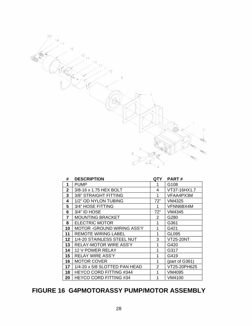
FIGURE 16 G4PMOTORASSY PUMP/MOTOR ASSEMBLY
# DESCRIPTION QTY PART #1 PUMP 1 G1082 3/8-16 x 1.75 HEX BOLT 4 VT37-16HX1.73 3/8” STRAIGHT FITTING 1 VFAA4PX3M4 1/2” OD NYLON TUBING 72” VM43255 3/4” HOSE FITTING 1 VFNN6BX4M6 3/4” ID HOSE 72” VM43457 MOUNTING BRACKET 2 G2808 ELECTRIC MOTOR 1 G36110 MOTOR -GROUND WIRING ASS’Y 1 G42111 REMOTE WIRING LABEL 1 GL09512 1/4-20 STAINLESS STEEL NUT 3 VT25-20NT13 RELAY-MOTOR WIRE ASS’Y 1 G42014 12 V POWER RELAY 1 G31715 RELAY WIRE ASS’Y 1 G41916 MOTOR COVER 1 (part of G361)17 1/4-20 x 5/8 SLOTTED PAN HEAD 2 VT25-20PH62518 HEYCO CORD FITTING #344 1 VM409520 HEYCO CORD FITTING #34 1 VM4100

29
FIGURE 17 PRO/portioner PANEL

30
Improper use of foam can be harmful to personnel and the environment. Followfoam concentrate manufacture’s instructions and fire service training to avoid such things as:
- Using wrong type of foam on a fire. i.e. Class A foam on a Class B fire.- Mishandling of concentrates, some of which are flammable.- Causing environmental damage.
11.0 OPERATION
Operate the foam system by following the steps below. Refer to Figure 17 for panel orientation.
a) Check concentrate level in tank(s) and fill as required.
b) Attach hose and nozzle to foam discharge on truck.
c) Pressurize water line by opening its valve and/or turning on water pump. Maximum operatingpressure for the PRO/portioner is 300 PSI.
d) Turn selector knob on panel to A or B position. This opens the valve from selected concentratetank to rest of system and also turns on concentrate pump. GREEN LIGHT SHOULD BE FLASHING.
e) Set mode knob to PRIME. This allows air to be expelled from the system. NOTE: Switching to flush mode momentarily can act as a "power prime" and help the system prime quicker. Pump has primed when steady flow is indicated on flow indicator. NOTE: Stay in prime mode no longer than necessary as concentrate is wasted through the vent tube once pump has primed.
f) Set mode knob to FOAM. System will now inject concentrate into the water stream wheneverwater is flowing. Check for concentrate flow in “Concentrate Flow Indicator”. Adjust percent knob asrequired. With nozzle shut down no concentrate is added to hose line. Stay in this mode as long asfoam is desired.
g) With water line still pressurized, set mode knob to FLUSH position for at least one minute. Thisallows water from the water stream to circulate through the concentrate pump and block, flushingconcentrate out of the system through the vent tube. DO NOT FLUSH IF UNIT WILL BE SUBJECT TO FREEZING TEMPERATURES.
h) Turn selector knob to OFF position.
i) After the unit is shutoff, return the mode selector knob to FOAM. Failure to do so will result inpressurized water from the venturi being forced through the pump and out the drain tube next timethey use the truck.
Lack of foam can place the nozzle operator at risk of injury or death. Establishfoam flow before advancing into dangerous situations. Assure against runningout of foam. Check concentrate level periodically and keep an adequate supplyon hand.
In compressed air foam systems (CAFS) loss of foam concentrate flow will causeslug flow and high impulsive nozzle reactions. Unit must be closely monitored toavoid this.

31

32
2800 East Evans Avenue • Valparaiso, IN 46383-6940800.348.2686 • 219.462.6161 • Fax 219.464.7155
http://www.tft.comLKG-101 June 11, 1999 Rev 11