operation, safety, and maintenance manual · pdf fileoperation, safety, and maintenance...
TRANSCRIPT

EM-549 (N-05/11) COPYRIGHT 2011CINCINNATI INCORPORATED
CINCINNATIR
OPERATION, SAFETY, AND MAINTENANCE MANUAL
CINCINNATIR
SE SEriES hydraulic ShEar
C I N C I N N AT I I N C O R P O R AT E DC I N C I N N A T I , OHIO 4 5 2 1 1


TiTlE cONTENTS
EM-549 (N-05/11)
SE SEriES hydraulic ShEar cONTENTSINTRODUCTION
SECTION 1 IDENTIfICATION
SECTION 2 INSTAllATIONUNLOADING ..................................................................................................2-1LIFTING AND MOVING ..................................................................................2-1FOUNDATION ................................................................................................2-1REMOVING SKIDS ........................................................................................2-1CLEANING .....................................................................................................2-1LEVELING ......................................................................................................2-2
LEVELING PROCEDURE ........................................................................2-2FINAL LEVEL CHECK ..............................................................................2-2
ELECTRICAL CONNECTION ........................................................................2-2HYDRAULIC RESERVOIR DRAIN ................................................................2-3INITIAL LUBRICATION ...................................................................................2-3INITIAL STARTUP ..........................................................................................2-3
TO START MACHINE ...............................................................................2-3
SECTION 3 SAfETYSAFETY RECOMMENDATIONS FOR HYDRAULIC SHEAR OPERATION ..3-1FOR SAFE OPERATION OF THE CINCINNATI SE HYDRAULIC SHEAR ...3-1
KEEP CLEAR OF WORK AREA ..............................................................3-1CONCENTRATE ON THE JOB ................................................................3-1NEATNESS IS IMPORTANT ....................................................................3-1PROPER TOOLS ARE IMPORTANT .......................................................3-1LOOK THINGS OVER CAREFULLY ........................................................3-2KNOW THE MACHINE’S CAPACITY .......................................................3-2SAFETY GUIDELINES .............................................................................3-3SAFETY - DANGER .................................................................................3-3HAZARDOUS AREA.................................................................................3-3
SHEAR OPERATOR SAFETY GUIDELINES .................................................3-4SAFETY MAINTENANCE CHECK .................................................................3-4
SECTION 4 SPECIfICATIONSSPECIFICATIONS ..........................................................................................4-1SPECIFICATIONS - METRIC .........................................................................4-2SHEAR OPERATING PRINCIPLE .................................................................4-3RAKE AND STROKE CONTROL ...................................................................4-3
SECTION 5 SETUP AND USEOPERATING RULES AND PRECAUTIONS ..................................................5-1SHEARING EXPLANATION ...........................................................................5-2
SHEARING AT LEFT OR RIGHT END .....................................................5-3GRADE OF MATERIAL ............................................................................5-3DISTORTION OF PIECES .......................................................................5-3BOW .........................................................................................................5-3TWIST ......................................................................................................5-3CAMBER ..................................................................................................5-3
SHEARING PROCEDURE .............................................................................5-4SHEARING OPERATIONS ............................................................................5-4
SQUARING BLANKS ...............................................................................5-4SQUARING LARGE SHEETS OR PLATES .............................................5-4STRIPPING ..............................................................................................5-4SHEARING NARROW WIDTHS ..............................................................5-4BLANKING ...............................................................................................5-4MAKING TRIANGULAR GUSSETS .........................................................5-6SHEET SPLITTING ..................................................................................5-7SLITTING .................................................................................................5-7

EM-549 (N-05/11)
SECTION 6 MACHINE CONTROlSMAIN ELECTRICAL ENCLOSURE ................................................................6-1OPERATOR CONTROL CONSOLE ...............................................................6-1DIGITAL GAGE CONTROL ...........................................................................6-4
SECTION 7 OPERATIONDAILY START UP ...........................................................................................7-1POWER DOWN ..............................................................................................7-1KNIFE CLEARANCE ......................................................................................7-1
USE OF TABLE SHIMS ...........................................................................7-1GAGES ...........................................................................................................7-3
BACKGAGE .............................................................................................7-3SIDE GAGE ..............................................................................................7-3GRADUATED SCALES IN TABLE ...........................................................7-3FRONTGAGE SUPPORT ARMS (OPTIONAL) ........................................7-3
OPERATION ...................................................................................................7-4
SECTION 8 OPTIONSADDITIONAL FOOTSWITCH .........................................................................8-1AIR-OPERATED BALL TRANSFERS ............................................................8-1FRONT SUPPORT ARMS ..............................................................................8-1SQUARING ARM ............................................................................................8-1FRONT GAGE STOPS ...................................................................................8-1GRADUATED SCALES ..................................................................................8-2HOLDDOWN CUPS .......................................................................................8-2HYDRAULIC OIL HEATER .............................................................................8-2LIGHT BEAM SHEARING GAGE ...................................................................8-2POWER FRONT FEED ROLLS .....................................................................8-2POWER OPERATED KNIFE CLEARANCE ...................................................8-3REAR CORNER SUPPORT ...........................................................................8-3SLITTING GAGE ............................................................................................8-3
SECTION 9 MAINTENANCE AND ADJUSTMENTSCHANGING OR ROTATING KNIVES .............................................................9-1
ADJUSTING MINIMUM KNIFE CLEARANCE .........................................9-3SHIMMING LOWER KNIFE .....................................................................9-4CALIBRATING BACKGAGE POSITION ..................................................9-8RAM GUIDE CLEARANCE .................................................................... 9-11LUBRICATION ........................................................................................ 9-11HYDRAULIC SYSTEM ...........................................................................9-12CHECKING AND SETTING PRESSURES ............................................9-14ACCUMULATOR ....................................................................................9-16LIGHT BEAM SHEARING GAGE ...........................................................9-16
TROUBLESHOOTING .................................................................................9-17MAINTENANCE CHECKLIST - SE SERIES HYDRAULIC SHEARS ..........9-19
SECTION 10 SERVICE AND PARTSORDERING REPAIR PARTS .......................................................................10-1RETURNING PARTS FOR CREDIT .............................................................10-1SERVICE ......................................................................................................10-1

INTRODUCTION
CINCINNATI SE SERIES HYDRAULIC SHEAR
The SE Series Shear is a hydraulically driven shear. Linear potentiometers constantly monitor the bed-to-ram position, feeding this information to the control. Electronically variable cut length and rake angle result in fast stroking speeds. A wide range of materials and thicknesses can be processed with optimum results through electronic setting of rake angle. Part distortion is minimized and cut blank quality is improved.
PART QUALITY
The following factors affect part quality:
Condition of the shear•Ability of the operator•Condition of the knives•Quality of the material•
CINCINNATI machines are designed to be rugged and durable, requiring low maintenance. However, an out of adjustment condition or lack of maintenance can reduce the quality of parts produced on these machines. Superior part edge condition is ensured by proper use of the knife clearance adjustment. A more perpendicular cut results in clean edges and minimum burr.
Operator ability affects part quality and production rate. CINCINNATI INCORPORATED provides many design features in the machine to aid the operator to produce consistent parts. For example, hydraulic holddowns provide tons of force to clamp the material and prevent movement during cutting. The operator or setup person must select the type of gaging, material supports, safeguarding, and special equipment to be used for each application to obtain optimum results. Selecting the proper shearing sequence is important to obtain quality parts and for operator safety.
Worn, damaged, or poor quality knives can directly affect the part quality. Using sharp knives, selecting the correct type of knives for the material, and setting the correct knife clearance is essential for producing good quality parts.
Quality of material can affect the quality of the sheared edge. Commercial steels may have hard and soft spots in the metal which can result in a ragged sheared edge. Using a good grade of material, along with sharp and properly adjusted knives, will produce good quality sheared parts.


1-1 EM-549 (N-05/11)
SEcTiON 1 idENTificaTiON
Clevis Pin1. Right Housing2. Right Cylinder3. Right Piston Socket4. Holddown Beam5. Awareness Barrier6. Automatic Lubricator7. Hydraulic Holddown (Behind Awareness Barrier)8. Table9. Gap Guard10. Table Stop Screw (As Shown with Power Knife Adjust)11. Jacking Lug12. Bed13. Footswitch14. Power Feed Rolls Control Console15.
Operator Control Console16. Power Front Feed Rolls17. Ball Transfer (within Table)18. Capacity Plate19. Left Piston Socket20. Left Cylinder21. Cylinder Roller22. Left Housing23. Lifting Hole24. Linear Potentiometer25. Light Beam Shearing Gage26. Main Drive Motor27. Ram28. Reservoir/Housing Brace29.
Figure 1-1 - Front View

1-2EM-549 (N-05/11)
Oil Sight Gage1. Hydraulic Fluid Specification Plate (Not Shown)2. Electrical Enclosure3. Backgage Lift Cylinder4. Jacking Lug5. Bed6. Backgage Angle7. Scrap Chute (Not Shown)8. Backgage Torque Tube9.
Rear Barrier and Danger Sign10. Backoff cylinder11. Gage Adjusting Collar12. Backgage Guide13. Ram Brace14. Reservoir / Housing Brace15. Lower Right Cylinder Line16. Hydraulic Manifold17.
Figure 1-2 - Rear View

1-3 EM-549 (N-05/11)
Hydraulic Reservoir Drain Valve1. Backgage Lift Cylinder2. Backgage Angle3. Backgage Motor4.
Figure 1-3 - Rear View(Note: The Rear Barrier and Danger sign have been removed for illustration purposes.)

1-4EM-549 (N-05/11)
Air Cooled Heat Exchanger1. Automatic Lubricator2. Manual Pocket (Location designated for blue manual)3.
Figure 1-5 - Right Side View(Note: The Rear Barrier and Danger sign have been removed for illustration purposes.)

2-1 EM-549 (N-05/11)
SEcTiON 2 iNSTallaTiONUNlOADINGUpon receipt of the CINCINNATI SE Hydraulic Shear, carefully remove contents of the one or more packing boxes with the machine. All loose parts, such as wrenches, tools, front support arms, rear safety cable and supports, etc., will be found in these boxes. Check the parts received against packing list contained in the tool box. Claims for shortages or damaged parts should be made within ten (10) days. Remove all shipping paper from the wrapped parts of the shear.
lIfTING AND MOVINGCINCINNATI SE Hydraulic Shears are usually shipped assembled and on skids. They are readily handled by a craneofsufficientcapacitywithchainsorcableadjustedto proper length for even lifting (Refer to ANSI Standard 830.9). Refer to specification chart in Section 4 - SPECIFICATIONS for approximate weights. A typical lifting arrangement is shown in Figure 2-1.
Figure 2-1 - Lifting
Where crane facilities are insufficient in capacity ornot available, rig the machine into the final location.Where rolling is easy, it is frequently desirable to rig the machineintothefinallocationevenwherecraneserviceis
available. Be careful to keep the machine supported evenly. CINCINNATI recommends employing professional riggers to handle the machine to ensure against damage to the machine or injury to workers.
fOUNDATIONA rigid foundation is essential. It must be able to support the machine without settling. Money spent on a proper foundation is a good investment. For details of the foundation,refertothecertifiedFoundationPlanDrawingpreviouslyfurnished.Asafinalcheck,seethattheanchorbolts in the foundation coincide with the bolt hole spacing in the housing feet.
REMOVING SKIDSLift the machine with a crane to remove the skids. If no crane is available, the shear should be rigged into position directly over the foundation bolts. Jack up the shear one end at a time in approximately 4” (100mm) steps and block until the skid can be removed. Remove skids and lower each end alternately by removing blocking in steps of about 4” (100mm) until foundation bolts extend into housing feet.
IMPORTANT: Shears equipped with a optional conveyor may require riser blocks to be placed on the foundation bolts before the shear is lowered into position.
On the 4SE and 6SE Series Shears, run the hex socket leveling screws down so that the shear rests on these screws. Lower the shear onto the foundation. Do not allow shear to permanently rest on leveling screws. On shears larger than the 6SE, jack lugs are provided on the housings for leveling instead of the leveling screws.
ClEANINGRemove all paper and plastic wrappings from the machine. Thoroughly clean protective grease from all parts of the machine. Use a rag wet with an aliphatic solvent, such as mineral spirits, and go over this grease, allowing it to soak. Use rags instead of waste. A stiff brush will get into the corners. Do not use an air hose as its pressure will drive grit and dirt into bearing surfaces. After cleaning thoroughly, wipe dry, and make sure no grease or grit is left. Remove the blocks under the ram by driving them out, so that the ram will be hanging free. Periodic cleaning of the machine after installation is advisable.
2-2EM-549 (N-05/11)
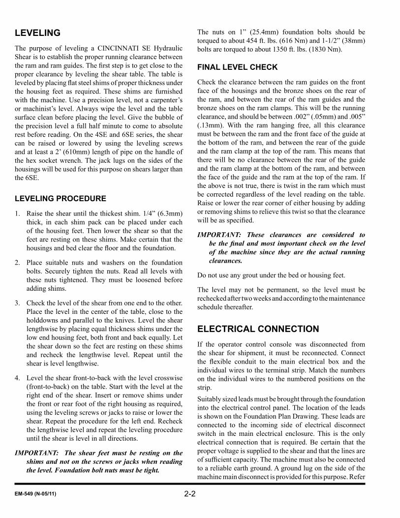
lEVElINGThe purpose of leveling a CINCINNATI SE Hydraulic Shear is to establish the proper running clearance between theramandramguides.Thefirststepistogetclosetotheproper clearance by leveling the shear table. The table is leveledbyplacingflatsteelshimsofproperthicknessunderthe housing feet as required. These shims are furnished with the machine. Use a precision level, not a carpenter’s or machinist’s level. Always wipe the level and the table surface clean before placing the level. Give the bubble of the precision level a full half minute to come to absolute rest before reading. On the 4SE and 6SE series, the shear can be raised or lowered by using the leveling screws and at least a 2’ (610mm) length of pipe on the handle of the hex socket wrench. The jack lugs on the sides of the housings will be used for this purpose on shears larger than the 6SE.
lEVElING PROCEDURE
Raise the shear until the thickest shim. 1/4” (6.3mm) 1. thick, in each shim pack can be placed under each of the housing feet. Then lower the shear so that the feet are resting on these shims. Make certain that the housingsandbedclearthefloorandthefoundation.
Place suitable nuts and washers on the foundation 2. bolts. Securely tighten the nuts. Read all levels with these nuts tightened. They must be loosened before adding shims.
Check the level of the shear from one end to the other. 3. Place the level in the center of the table, close to the holddowns and parallel to the knives. Level the shear lengthwise by placing equal thickness shims under the low end housing feet, both front and back equally. Let the shear down so the feet are resting on these shims and recheck the lengthwise level. Repeat until the shear is level lengthwise.
Level the shear front-to-back with the level crosswise 4. (front-to-back) on the table. Start with the level at the right end of the shear. Insert or remove shims under the front or rear foot of the right housing as required, using the leveling screws or jacks to raise or lower the shear. Repeat the procedure for the left end. Recheck the lengthwise level and repeat the leveling procedure until the shear is level in all directions.
IMPORTANT: The shear feet must be resting on the shims and not on the screws or jacks when reading the level. Foundation bolt nuts must be tight.
The nuts on 1” (25.4mm) foundation bolts should be torqued to about 454 ft. lbs. (616 Nm) and 1-1/2” (38mm) bolts are torqued to about 1350 ft. lbs. (1830 Nm).
fINAl lEVEl CHECK
Check the clearance between the ram guides on the front face of the housings and the bronze shoes on the rear of the ram, and between the rear of the ram guides and the bronze shoes on the ram clamps. This will be the running clearance, and should be between .002” (.05mm) and .005” (.13mm). With the ram hanging free, all this clearance must be between the ram and the front face of the guide at the bottom of the ram, and between the rear of the guide and the ram clamp at the top of the ram. This means that there will be no clearance between the rear of the guide and the ram clamp at the bottom of the ram, and between the face of the guide and the ram at the top of the ram. If the above is not true, there is twist in the ram which must be corrected regardless of the level reading on the table. Raise or lower the rear corner of either housing by adding or removing shims to relieve this twist so that the clearance willbeasspecified.
IMPORTANT: These clearances are considered to be the final and most important check on the level of the machine since they are the actual running clearances.
Do not use any grout under the bed or housing feet.
The level may not be permanent, so the level must be rechecked after two weeks and according to the maintenance schedule thereafter.
ElECTRICAl CONNECTIONIf the operator control console was disconnected from the shear for shipment, it must be reconnected. Connect the flexible conduit to the main electrical box and theindividual wires to the terminal strip. Match the numbers on the individual wires to the numbered positions on the strip. Suitably sized leads must be brought through the foundation into the electrical control panel. The location of the leads is shown on the Foundation Plan Drawing. These leads are connected to the incoming side of electrical disconnect switch in the main electrical enclosure. This is the only electrical connection that is required. Be certain that the proper voltage is supplied to the shear and that the lines are ofsufficientcapacity.Themachinemustalsobeconnectedto a reliable earth ground. A ground lug on the side of the machine main disconnect is provided for this purpose. Refer

2-3 EM-549 (N-05/11)
to local and state codes for acceptable grounding methods. Do not start the main drive until Section 3 - SAFETY and Section 7 - OPERATION of this manual have been thoroughly read and understood and a CINCINNATI INCORPORATED Service Representative is present.IMPORTANT: At this point call the CINCINNATI
INCORPORATED Service Representative before proceeding any further. DO NOT START THE MACHINE. The Service Representative will check the installation and machine thoroughly before start-up.
HYDRAUlIC RESERVOIR DRAINThe hydraulic reservoir is supplied with a drain valve (Item 1, Figure 1-3). Before starting the pump, open this valve to drain any water that may have collected in the tank during shipment. If no water comes out, or when oil starts coming out, close the valve securely. Repeat this check monthly.
INITIAl lUBRICATIONCINCINNATI SE Hydraulic Shears are shipped with the hydraulic reservoir filled with oil. The SE Shearsare equipped with an automatic sight feed lubricator that provides adequate oiling under pressure to all guide surfaces, backgage guides, and screws. Before starting the hydraulic shear, make the following lubrication checks:
HYDRAULIC RESERVOIR1. : Check oil level in sight glass on rear of hydraulic reservoir. Keep the reservoir filled with hydraulic oil as specified in Section 9 - MAINTENANCE AND ADJUSTMENTS.
AUTOMATIC LUBRICATOR:2. This lubricator is mounted on the outside of the right housing (Item 7, Figure 1-1). After the shear has been cleaned, turn the hand crank on the lubricator until oil is dripping off the ram guides, especially note the left guide. The lubricator automatically feeds oil when the machine is operating. When the machine is started up after standing idle for 48 hours, turn the hand crank until oil appears at the left guide. CINCINNATI suggests at least 40 turns of the hand crank. The lubricator should berefilledwhentheoilgetsdowntothelowerwindowwith a good grade of machine oil. Use oil with viscosity of about 300 SUS at 100°F (C.I. Oil B-315), capacity one gallon (3.8 L).
BACKGAGE:3. Backgage guides are lubricated by the automatic lubricator. For further information on lubrication, see Section 9 - MAINTENANCE AND ADJUSTMENTS.
INITIAl STARTUPBefore starting the shear, the Section 3 - SAFETY, Section 5 - SETUP AND USE, Section 6 - MACHINE CONTROLS, and Section 7 - OPERATION sections of this manual must be read and thoroughly understood by every operator assigned to this shear. Special emphasis should be given to the following:
WHEN THE MACHINE IS NOT IN USE, ALWAYS •RUN THE RAM TO THE BOTTOM OF THE STROKE.
WHENEVER LEAVING THE SHEAR, •ALWAYS TURN THE OPERATOR CONTROLS SELECTOR TO THE “OFF” POSITION AND REMOVE THE KEY.
NEVER PLACE ANY PART OF THE BODY IN •THE KNIFE OR HOLDDOWN AREA.
IMPORTANT: A CINCINNATI INCORPORATED Service Representative should be present during initial start up of the shear. Before starting the drive motor the following checks should be made:
Installation has been completed as determined 1. by a CINCINNATI INCORPORATED Service Representative, including:
Foundationa. Cleaningb. Levelingc. Initial lubrication (including checking oil level d. and for water in the reservoir)Electrical connections and servicee.
All machine options have been installed on the 2. machine.
The machine has been completely visually inspected.3.
Before stroking the ram, the table and lower knife 4. should be moved toward the front, away from the upper knife to avoid any possibility of the knives clashing. Refer to KNIFE CLEARANCE in Section 7 - OPERATION.
TO START MACHINE
Turn the main disconnect switch on.1.
Turn the OPERATOR CONTROLS selector and the 2. MODE selector to the “OFF” position.
Jog the drive motor with the START and STOP buttons 3.

2-4EM-549 (N-05/11)
and make certain that pump rotation is counterclockwise (looking from pump end). If the rotation is not correct, reverse two incoming leads to the main disconnect switch. Now press the START button and bring the pump up to full speed.
Turn the MATERIAL THICKNESS and MATERIAL 4. LENGTH controls fully clockwise.
Turn the OPERATOR CONTROLS selector to the 5. “ON” position.
Turn the MODE selector to the “INCH” position.6.
Depress the footswitch momentarily to activate the 7. READY light.
The machine is now ready for a full-length stroke. Use 8. the footswitch and cycle the shear for at least twenty strokes to work any air out of the system. Stop the ram at the top.
All controls, electrical functions, and safety features 9. should be checked for proper operation.
Before doing any shearing, it will be necessary 10. to check and adjust knife clearance. Refer to the explanation of KNIFE CLEARANCE and USE OF TABLE SHIMS in Section 7 - OPERATION and to ADJUSTING KNIFE CLEARANCE (Non-Powered or Powered) in Section 9 - MAINTENANCE AND ADJUSTMENTS.

3-1 EM-549 (N-05/11)
SEcTiON 3 SafETySAfETY RECOMMENDATIONS fOR HYDRAUlIC SHEAR OPERATIONShears manufactured today by CINCINNATI INCORPORATED comply with the construction requirements of the Occupational Safety and Health Act and the National Safety Standards of the American National Standards Institute. CINCINNATI recommends reading and understanding the safeguarding use and care requirements of the American National Standard for Safety Requirements for Shears, ANSI B11.4. This is available from the American National Standards Institute, 25 West 43rd Street, New York, NY, 10036. A copy is included in the manual pouch with each new machine.
For additional safety information CINCINNATI recommends:
Securing applicable safety data sheets from the •National Safety Council, 1121 Spring Lake Drive, Itasca, Illinois 60143-3201.Determining responsibilities under state and local •safety codes.Requesting assistance from the loss prevention •department of the workmen’s compensation carrier.
Personnel responsible for shear operator training program, maintenance, and operations must read and understand this Operation, Safety, and Maintenance manual, No one should set up, operate, or maintain this shear until thoroughly understanding it and knowing how to do the job safely. This safety information is not intended as a substitute for Section 7 - OPERATION and Section 9 - MAINTENANCE AND ADJUSTMENTS of this manual.
fOR SAfE OPERATION Of THE CINCINNATI SE HYDRAUlIC SHEARKEEP ClEAR Of WORK AREAKeep fingers, hands, arms and all parts of the body outof the work area (point-of-operation). Be aware that this machine is a shear and it will cut almost anything that has entered the work area if the shear is activated. The shear is also equipped with powerful holddowns which exert tons of force, clamping material or anything else in the work area while the ram is cycled. This is why awareness barriers and point-of-operation guards were put on the shear. Do not remove the guards or try to get past them when operating
the shear.
If the machine is operated by more than one person and an operator control is not provided for each additional operator, only one operator should have the responsibility for activating the machine. It should be that operator’s responsibility to see that everyone, including coworkers and all bystanders, are clear of the work area and all moving parts, and that they are entirely visible in a safe location before activating the shear. Make sure that no one is in the area below the moving ram brace and backgage mechanism. Injury could result from being struck by these moving parts or by being crushed between them and stacked material.
During setup, maintenance, or adjustments on the machine which requires working within the work area, the ram should be blocked so that the knives cannot close and the power supply should be entirely disconnected.
CONCENTRATE ON THE JOB
Daydreaming, worrying about other problems, or improper operation of a machine could cripple a person for life. Operating a shear requires the operator’s complete attention. Talking, joking, or participating in or watching horseplay could result in physical injury. Concentrate on the job.
NEATNESS IS IMPORTANT
Keep thefloorof theworkarea clearof scrapand trashthat could cause someone to stumble. Put scrap in the propercontainersandkeepstockandfinishedworkneatlyarranged. Be sure slippery surfaces are cleaned up properly, stumbling and slipping can result in painful and perhaps even fatal injuries.
Put all tools and equipment away when not in use. Only the material currently being worked with should be on the table when operating the machine. Even a screwdriver can be deadly if left on the table of the machine.
PROPER TOOlS ARE IMPORTANT
Use the proper tools when working on the shear. An improper tool might slip and cause cuts or bruises. When changing knives, making adjustments, or making repairs to the machine, be sure the ram is blocked in place or is at the bottom of the stroke and the power source is disconnected.

3-2EM-549 (N-05/11)
All blocks must be removed prior to returning the machine to normal service to prevent damage. Loose or flowingclothes may be comfortable, but if they are caught on the machine, it could result in an injury. Keep jewelry to a minimum. Never work through the throat of the shear or between the housings to handle or support material.
lOOK THINGS OVER CAREfUllY
Before operating the CINCINNATI SE Hydraulic Shear, look to see if the machine is in the proper condition:
Are the knives worn or chipped? •Isthefloorclearofrubbish?•Are all tools put away? •Is the stock neatly arranged? •Are the machine’s covers and guards securely in •place? Isthemachinefirmlyanchoredtothefloor?•Are all nuts, bolts, and screws tight? •Is everything in proper operating condition? •
If not, report the unsafe condition and needed repairs to the supervisor and be sure the problem is corrected before beginning operations.
KNOW THE MACHINE’S CAPACITY
Check the SHEAR SPECIFICATIONS chart in this manual for the mild steel capacity of the shear. Check the charts in Shear Capacities Bulletin PT-30491 included with this manual for the capacity of the shear and knives for the metal being sheared. Be sure that the rake is properly set for the material being cut. Do not attempt to cut material thicker than the rated capacity of the machine. The maximum mild steel capacity for this shear is also shown on the capacity plate in the center of the holddown beam or on the left housing.
fOR SAfE OPERATION Of THE CINCINNATI SE HYDRAUlIC SHEAR fOllOW THESE RUlES:
Be sure to know how to operate and adjust the 1. CINCINNATI SE Hydraulic Shear. Inspect the machine to see that all guards are in place. Review Section 6 - MACHINE CONTROLS and Section 7 - OPERATION of this manual.
Be sure that the shear knives are sharp and have the 2. proper clearance. Make certain adequate safeguarding is installed.
Use a hand tool to position or remove small pieces. 3. Keep hands away from the knives and from underneath
the holddowns.
Use a bench brush to clean off the shear table. Never 4. use bare hands. Metal slivers can be painful.
Protecttheeyesfromflyingpiecesofmetalbyalways5. wearing safety glasses.
Never place hands under the holddowns or in the 6. knives. Do not insert hands into, through, or underneath the safeguarding.
Be sure that fingers are not between the workpiece7. and the table. The clamping force needed to hold the workpiece to the table is more than enough to crush or evenamputateahandorfingers.
Wear safety shoes at all times. A heavy or pointed 8. piece of stock could fall and cause serious injury to the foot.
Keep the shear table free of loose tools and materials.9.
Wear snug fitting hand and arm protection when10. handling rough or sharp-edged stock.
Placestockbeingshearedfirmlyagainst thestopsor11. gages before pressing the footswitch. Always use the holddowns, even for small pieces of stock, to prevent “tip-up” injury. Never shear a piece that is not held by at least one holddown clamp.
When shearing capacity or near capacity thickness 12. material, try to use at least two holddowns to prevent “tip-up”. A work clamp may be required for narrow pieces. See Section 5 - SETUP AND USE for instructions on shearing narrow pieces.
Keep the rear of the shear clear of scrap and sheared 13. material. Use chutes, conveyors, or metal receiving boxes. DO NOT operate shear until certain no one is in rear area of the shear. Remember that the backgage guides and ram brace move up and down with the ram.
Make certain no one is exposed to any moving parts of 14. the shear at the rear, front, or sides before operation.
For emergency stops on the shear simply release the 15. footswitch. The ram will return to the top of stroke when in “SINGLE STROKE” or “CONTINUOUS”, or will stop immediately when in “INCH”.
Turn off the OPERATOR CONTROLS selector switch, 16. lock it, and take the key when leaving the machine, even if leaving the machine for only a few minutes.

3-3 EM-549 (N-05/11)
Maintain proper lighting levels and eliminate light 17. glare to prevent eye strain and eye fatigue.
Report all cuts, bruises, or other injuries to the supervisor 18. or the medical department immediately. They are the best judges of the seriousness of an injury.
A number of warnings signs are attached to all CINCINNATI SE Hydraulic Shears as a reminder to shear operators and maintenance personnel that certain hazards will exist, unless specifiedproceduresarefollowed.Warningsignsarenotintended to be a substitute for reading and understanding this Operation, Safety, and Maintenance manual. The warning signs are placed at strategic points on the shear for most effective use. It is intended that they become a permanent part of the equipment and, therefore, must not be removed, covered, hidden, or defaced. All signs installed on the machine by CINCINNATI INCORPORATED are identifiedbyasmallsix-digitpartnumber locatedin thelower right corner. If any of these signs become damaged or defaced, new ones should be ordered by contacting the factory or the nearest CINCINNATI Sales and Service office.Thefollowingillustrationsshowthewarningsignsmost commonly used on the hydraulic shears. Other signs will be used when optional or special equipment is furnished on the machine. The user management should also include additional warning signs to cover any hazards that may be presented by customer-added auxiliary equipment.
SAfETY GUIDElINES
This warning sign is attached to the front of the shear. The sign provides a checklist of safety considerations which should be observed before, during, and after operation of the shear.
SAfETY - DANGER
This sign is a reminder to the machine operators or the maintenance personnel that certain procedures must be followed to prevent serious bodily injury.
HAZARDOUS AREA
This sign warns of a hazardous area at the rear of the shear. One sign is attached to a steel restraining cable, which spans the space between bars attached to the housings. Another sign is attached to a rear surface of the machine. No one should enter this area when the machine is in operation.

3-4EM-549 (N-05/11)
SHEAR OPERATOR SAfETY GUIDElINES
Know the shear: capacity, controls, operating modes, •and safeguarding.
Adequate safeguarding is properly installed.•
The knives are sharp and the clearance is correct.•
The clamping mechanism/holddowns are operating •properly.
The workpiece is clamped by one or more holddowns.•
The work area is clear, both front and rear.•
The shear table is free of loose tools and materials.•
Hand tools and personal protective devices are •available and used: tools, safety glasses, gloves, safety shoes,etc.Wearsnugfittingclothes.
Keep hands out of the point-of-operation and from •between the workpiece and the shear table.
Make certain all personnel are away from the shear •before operating.
Keep alert: focus on the job being completed.•
When leaving the shear, turn the power off and be sure •the controls are inoperative.
Safety is a part of any job. The chance of serious injury to employees is less when more attention is paid to safety,
SAfETY MAINTENANCE CHECKThe safeguarding at the point-of-operation is in proper •adjustment and repair.
The pinch point guarding is properly installed. •
The Operator Controls are working properly.•
The Operating Modes are functioning properly.•
The ram is starting and stopping properly.•
The instruction and warning signs are clean and easily •read.
The knives are checked for sharpness and proper •clearance.
The electrical wiring is in good condition.•
The holddowns or clamping mechanism is operating •properly.
The caution painting is in good condition.•
The auxiliary equipment is checked and is working •properly.
Hand tools and personal protection equipment are in •good order and are readily available.
The safety manuals and operator manuals are attached •to the machine.
The scheduled normal maintenance work is complete.•
failure to follow safe shear operating procedures may result in serious injury to employees.

4-1 EM-549 (N-05/11)
SEcTiON 4 SpEcificaTiONSSPECIfICATIONS
MATERIAlCAPACITY
MIlD STEEl
(Inches)*
MIN. MATERIAl
THICK. (Inches)
**
SERIESMAX. RAKE(in./ft.)
HOlDDOWNS GAGE RANGE RAM SPEED(in./min.)
STROKES/MINUTE
MO
TOR
KNIfE SIZE
(Inches)
APPROX. SHIP
WEIGHT (lbs.)fORCE
(Tons) NO. BACK (Inches)
fRONT(Inches) UP
fUll lOAD DOWN
MAX.***
MIN.**** H.P.
.500 16 Ga.(.0598)
4SE06
.438
16 9
48
47
360 113
31 17
40 1 X 4
20,500
4SE08 19.5 11 47 30 14 22,800
4SE10 23 13 50 30 12 26,000
4SE12 26.5 15 54 30 11 33,200
4SE14 30 17 59 29 10 39,600
4SE16 33.5 19
60
64 29 9 48,300
4SE18 37 21 64 29 8 60,700
4SE20 40.5 23 65 28 7 72,300
.750 16 Ga.(.0598)
6SE06
.688
28.5 9
48
48.88
258 120
25 11
50 1.13 X 5
32,150
6SE08 35 11 48.88 25 10 35,350
6SE10 41.5 13 48.88 24 8 41,500
6SE12 47.5 15 52.88 24 7 46,700
6SE14 54 17 58.88 24 6 54,900
6SE16 60.5 19
60
58.88 23 6 71,300
6SE18 67 21 60.88 23 5 81,200
6SE20 73 23 64.88 22 5 90,300
1.000 16 Ga.(.0598)
8SE06
.750
39.5 9
48
62.25
175 78
16 7
50 1.5 X 5.5
48,600
8SE08 48 11 62.25 15 6 53,000
8SE10 57 13 62.25 15 5 64,500
8SE12 65.5 15 65.25 15 4 73,600
8SE14 74.5 17 68.25 14 4 83,900
8SE16 83 19
60
72.25 14 3 96,650
8SE18 92 21 74.25 14 3 112,000
8SE20 100 23 76.25 14 3 125,400
1.250 10 Ga.(.1345)
10SE06
.875
66 9
48
62.25
150 54
11 4
50 1.5 X 5.5
52,400
10SE08 86 11 62.25 11 4 57,700
10SE10 105 13 65.25 10 3 68,800
10SE12 124 15 68.25 9 3 79,900
10SE14 124 17 72.25 9 2 94,200
10SE16 124 19
60
76.25 9 2 107,500
10SE18 124 21 78.25 9 2 126,100
10SE20 124 23 80.25 8 2 141,400
1.500 .250
12SE06
1.00
66 748
65.5
133 52
10 4
60 1.75 X 6.5
75,020
12SE08 86 9 65.5 10 3 81,400
12SE10 105 11
60
65.5 9 3 98,540
12SE12 124 13 68.5 9 2 109,400
12SE14 124 17 68.5 9 2 118,500
12SE16 124 19 70.5 9 2 139,400
12SE18 124 21 72.5 8 2 156,700
12SE20 124 23 74.5 8 2 176,200
*The above capacities are for mild steel with 60,000 psi maximum tensile strength. For relative capacities of other materials, refer to Shear Capacities Bulletin PT-30491, included with this manual.
**When shearing minimum thickness, refer to KNIfE ClEARANCE in Section 7 - OPERATION.
***Maximum strokes per minute - 24” cut length at .125” rake angle.
****Minimum strokes per minute - Full-length capacity at maximum rake angle.
4-2EM-549 (N-05/11)
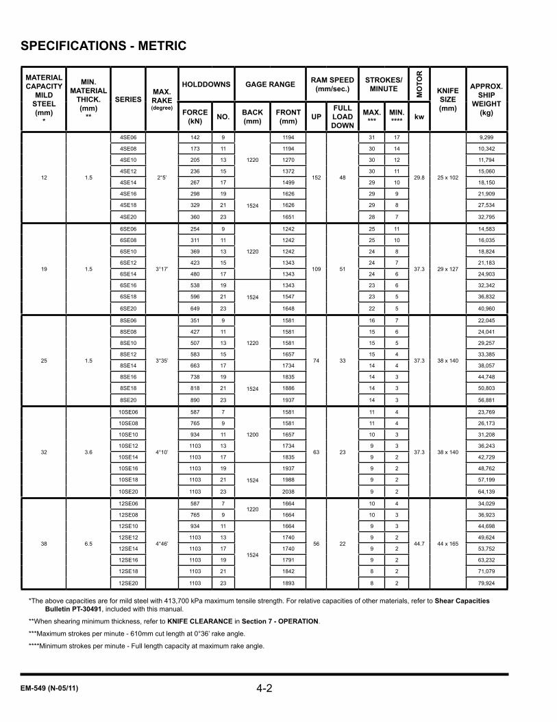
SPECIfICATIONS - METRIC
MATERIAlCAPACITY
MIlD STEEl(mm)
*
MIN. MATERIAl
THICK. (mm)
**
SERIESMAX. RAKE(degree)
HOlDDOWNS GAGE RANGE RAM SPEED(mm/sec.)
STROKES/MINUTE
MO
TOR
KNIfE SIZE (mm)
APPROX. SHIP
WEIGHT (kg)fORCE
(kN) NO. BACK (mm)
fRONT(mm) UP
fUll lOAD DOWN
MAX.***
MIN.**** kw
12 1.5
4SE06
2°5’
142 9
1220
1194
152 48
31 17
29.8 25 x 102
9,299
4SE08 173 11 1194 30 14 10,342
4SE10 205 13 1270 30 12 11,794
4SE12 236 15 1372 30 11 15,060
4SE14 267 17 1499 29 10 18,150
4SE16 298 19
1524
1626 29 9 21,909
4SE18 329 21 1626 29 8 27,534
4SE20 360 23 1651 28 7 32,795
19 1.5
6SE06
3°17’
254 9
1220
1242
109 51
25 11
37.3 29 x 127
14,583
6SE08 311 11 1242 25 10 16,035
6SE10 369 13 1242 24 8 18,824
6SE12 423 15 1343 24 7 21,183
6SE14 480 17 1343 24 6 24,903
6SE16 538 19
1524
1343 23 6 32,342
6SE18 596 21 1547 23 5 36,832
6SE20 649 23 1648 22 5 40,960
25 1.5
8SE06
3°35’
351 9
1220
1581
74 33
16 7
37.3 38 x 140
22,045
8SE08 427 11 1581 15 6 24,041
8SE10 507 13 1581 15 5 29,257
8SE12 583 15 1657 15 4 33,385
8SE14 663 17 1734 14 4 38,057
8SE16 738 19
1524
1835 14 3 44,748
8SE18 818 21 1886 14 3 50,803
8SE20 890 23 1937 14 3 56,881
32 3.6
10SE06
4°10’
587 7
1200
1581
63 23
11 4
37.3 38 x 140
23,769
10SE08 765 9 1581 11 4 26,173
10SE10 934 11 1657 10 3 31,208
10SE12 1103 13 1734 9 3 36,243
10SE14 1103 17 1835 9 2 42,729
10SE16 1103 19
1524
1937 9 2 48,762
10SE18 1103 21 1988 9 2 57,199
10SE20 1103 23 2038 9 2 64,139
38 6.5
12SE06
4°46’
587 71220
1664
56 22
10 4
44.7 44 x 165
34,029
12SE08 765 9 1664 10 3 36,923
12SE10 934 11
1524
1664 9 3 44,698
12SE12 1103 13 1740 9 2 49,624
12SE14 1103 17 1740 9 2 53,752
12SE16 1103 19 1791 9 2 63,232
12SE18 1103 21 1842 8 2 71,079
12SE20 1103 23 1893 8 2 79,924
*The above capacities are for mild steel with 413,700 kPa maximum tensile strength. For relative capacities of other materials, refer to Shear Capacities Bulletin PT-30491, included with this manual.
**When shearing minimum thickness, refer to KNIfE ClEARANCE in Section 7 - OPERATION.
***Maximum strokes per minute - 610mm cut length at 0°36’ rake angle.
****Minimum strokes per minute - Full length capacity at maximum rake angle.
4-3 EM-549 (N-05/11)
SHEAR OPERATING PRINCIPlECINCINNATI SE Hydraulic Shears have a single outlet, fixed displacement, vane type pump driven through aflexiblecouplingbyanelectricmotor.Whentheshearisidling, all oil displaced by the pump is discharged back to the tank through the vented center position of a tri-pressure relief valve. Stepping on the footswitch shifts the tri-pressure relief valve to the holddown pressure side. The holddown operating valve shifts simultaneously, causing full pump discharge to go into the holddown cylinders, causing the holddown plungers to clamp the sheet or plate on the table. This clamping pressure is controlled by an adjustment on the tri-pressure relief valve. This pressure is preset at the factory. A surplus amount of oil goes into the accumulator, which is used to maintain holddown pressure throughout the cutting stroke. Some of this oil goes into the backgage back-off cylinders, which pulls the backgage angle back after the material is securely clamped, to clear the piece cut off.
There is also a pressure switch in the holddown circuit. When the preset pressure is reached, this switch initiates a timer, which times out allowing the holddown circuit to stabilize, then initiates the cut cycle. The holddown operating valve closes, trapping the oil in the holddown system under pressure. It also shifts the tri-pressure relief valve to the main operating valve so that full pump output is discharged into the left cylinder over its piston. This causes the ram to descend. The pressure and resultant force is limited by an adjustment on the tri-pressure relief valve. If the holddown pressure drops below the pressure switch setting during the cut cycle, the ram will stop and the hydraulicfluidwillbedivertedtotheholddowncylinders.When the switch pressure setting is reached, the cycle will continue.
As the left piston descends, the oil in the rod end of the cylinder, which is displaced by the piston, is discharged into the top of the right cylinder over its piston. The net area below the left piston (cylinder area minus rod area) is equal to the net area above the right piston. The result is that the right piston will move down along with the left piston, by exactly the same amount. This is why the cylinders are of different size and the left piston rod is smaller.
At the bottom of the stroke, three valves shift. The holddown operating valve releases the trapped oil from the holddowns and the backgage back-off cylinders into the tank. This allows the holddowns to return to their up position, and the backgage angle to reset itself. The main operating valve then changes the pump output from the top of the left cylinder to the bottom of the right cylinder,
causing the ram to go up. The large piston rod on the right cylinder reduces the volume of oil required to raise the ram, so it will have a rapid return stroke. The tri-pressure relief valve shifts to the holddown pressure side. The rake control valve is also electrically activated if a rake correction is required.
At the top of the stroke, the main operating valve shifts to its neutral position, stopping the ram, and simultaneously the tri-pressure relief valve shifts to the vented center position.
RAKE AND STROKE CONTROlRake is the slope of the upper knife from one end to the other and is designated in inches rise per foot (degrees). The steeper the rake, the smaller the area of material that will be in shear at one time. This will reduce the force necessary for shearing. Conversely, lowering the rake will increase the area in shear at one time which will raise the force necessary for shearing. To change rake on a shear, one end of the ram must be raised or lowered relative to the other end. One of the advantages of a hydraulic shear is the fact that its rake can be easily changed. It can be increased so that the shear will cut heavy plate, or it can be decreased to cut thinner sheet with less distortion of the back piece and increase the productivity by shortening the stroke.
On a CINCINNATI SE Hydraulic Shear, the oil between the lower side of the left piston and the upper side of the right piston is trapped. This forms a closed circuit maintaining the relative positions of the two pistons. If oil is added to this closed circuit under pressure, it will force the left piston, increasing the rake. The right piston cannot go down as it is held up by the counterbalance valve. If some of this trapped oil is drained out, the left piston will come down, decreasing the rake. Adding or draining oil in this closed circuit is accomplished by a solenoid operated valve.
The length of the ram stroke is adjustable on a CINCINNATI SE Hydraulic Shear. The stroke length required for a cut depends on the length of the cut and the material thickness. Thicker materials and longer cuts require longer strokes.
Rake and stroke are controlled by the electronic rake and stroke control system. This system consists of a linear potentiometer mounted on each cylinder, two rotary potentiometers on the control console, and the rake and stroke controller, which consists of several printed circuit boards.

4-4EM-549 (N-05/11)
The rods on the linear potentiometers mounted on the cylinders are connected to the ball sockets on the top of the ram. See Figure 4-1. The rods extend as the ram moves down. The function of these potentiometers is to indicate the position of each cylinder piston to the controller. They each output a voltage which is proportional to their respective cylinder piston positions.
The two rotary potentiometers on the control console are used by the operator to adjust the rake and stroke. See Figure 6-1 in Section 6 - MACHINE CONTROLS. The MATERIAL THICKNESS potentiometer adjusts the rake, and the MATERIAL LENGTH potentiometer adjusts the stroke. Like the linear potentiometers, they also output a voltage to the controller which is proportional to their set positions.
The controller compares the output voltages from these various potentiometers to control the stroke and rake. The output voltage from the linear potentiometer mounted on the left cylinder is matched to the output voltage from the MATERIAL LENGTH potentiometer on the control console to control the ram stroke. The difference in output voltages from the two linear potentiometers on the cylinders is matched to the output voltage from the MATERIAL THICKNESS potentiometer on the control console to control the rake.
Figure 4-1 - Linear Potentiometer

5-1 EM-549 (N-05/11)
SEcTiON 5 SETup aNd uSEOPERATING RUlES AND PRECAUTIONSWhen shearing, there are several very important operation rules and precautions that must be followed. Observing these rules will promote accuracy and safe shear operation. Failure to adhere to the following recommendations will greatly increase the possibility of an accident, leading to serious personal injury and/or machine damage.
Never place fingers underneath the material to be1. sheared. The preferred method for feeding is to push the material into the shear with the heel of the hand using the hand slot locations in the table. Gloves must always be worn when handling material.
Be aware that the holddowns will clamp the material tothetable,flatteningoutsomeofthewavinessofthesheet or plate. This clamping action can cause injury if hands are between the material and the table.
Switching the optional air-operated ball transfers to the inoperative position will cause the supported material to come down onto the table. The weight of the material falling onto the table can cause injury to hands under the material.
There may be a tendency for the material to tip up when 2. sheared if using dull knives, improper knife clearance, over-capacity material, or inadequate holddown pressure. This is particularly true when shearing a piece held by one holddown or shearing narrow strips between holddowns.
All CINCINNATI Shears are equipped with hydraulic 3. holddowns which clamp the material being sheared to prevent movement or “tip-up” during shearing. CINCINNATI recommends that the material be clamped by as many holddowns as possible, at least two or more. The minimum width of material on the table should be such that it will be clamped by the full diameter of the holddown foot. This width will be different for each size shear, and should be equal to or greater than the distance from the cutting edge of the lower knife to the outer edge of the holddown foot. See Figure 5-1.
Figure 5-2 shows the guard and the relationship of the holddown foot to the shear table and to the cutting line at the lower knife. The minimum width of material on the table should be clamped by the full diameter of the holddown foot (dimension “C” plus “F”). The practical
minimum width of material that can be handled without special tools is limited by the guard-to-knife distance (dimension “D” or greater).
Figure 5-1 - Clamping Material
DIMENSION 4SE 6SE 8SE 10SE 12SEA - DISTANCE UNDER GUARD
1.00(25)
1.50(38)
2.00(51)
2.00(51) N/A
B - DISTANCE UNDER HOLDDOWN
1.00(25)
1.50(38)
2.00(51)
2.00(51) N/A
C - KNIFE TO HOLDDOWN FOOT
1.00(25)
0.94(24)
1.25(32)
1.25(32) N/A
D - KNIFE TO CENTERLINE OF BAR
6.00(152)
6.75(171)
8.00(203)
8.80(224) N/A
E - MAX. OPENING UNDER MOVEABLE SECTION
.25(6.4)
.25(6.4)
.25(6.4)
.25(6.4) N/A
F - HOLDDOWN FOOT DIA.
2.25(57)
3.00(76)
3.00(76)
4.00(102) N/A
Figure 5-2 - Holddowns and Guarding
5-2EM-549 (N-05/11)
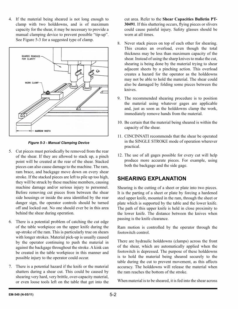
If the material being sheared is not long enough to 4. clamp with two holddowns, and is of maximum capacity for the shear, it may be necessary to provide a manual clamping device to prevent possible “tip-up”. See Figure 5-3 for a suggested type of clamp.
Figure 5-3 - Manual Clamping Device
Cut pieces must periodically be removed from the rear 5. of the shear. If they are allowed to stack up, a pinch point will be created at the rear of the shear. Stacked pieces can also cause damage to the machine. The ram, ram brace, and backgage move down on every shear stroke. If the stacked pieces are left to pile up too high, they will be struck by these machine members, causing machine damage and/or serious injury to personnel. Before removing cut pieces from between the shear sidehousingsorinsidetheareaidentifiedbythereardanger sign, the operator controls should be turned off and locked out. No one should ever be in this area behind the shear during operation.
There is a potential problem of catching the cut edge 6. of the table workpiece on the upper knife during the up-stroke of the ram. This is particularly true on shears with longer strokes. Material pick-up is usually caused by the operator continuing to push the material in against the backgage throughout the stroke. A kink can be created in the table workpiece in this manner and possible injury to the operator could occur.
There is a potential hazard if the knife or the material 7. shatters during a shear cut. This could be caused by shearing very hard, very brittle, over-capacity material, or even loose tools left on the table that get into the
cut area. Refer to the Shear Capacities Bulletin PT-30491.Ifthisshatteringoccurs,flyingpiecesorsliverscould cause painful injury. Safety glasses should be worn at all times.
Never stack pieces on top of each other for shearing. 8. This creates an overload, even though the total thickness may be less than maximum capacity of the shear. Instead of using the sharp knives to make the cut, shearing is being done by the material trying to shear adjacent sheets by a pinching action. This overload creates a hazard for the operator as the holddowns may not be able to hold the material. The shear could also be damaged by folding some pieces between the knives.
The recommended shearing procedure is to position 9. the material using whatever gages are applicable and, just as soon as the holddowns clamp the work, immediately remove hands from the material.
Be certain that the material being sheared is within the 10. capacity of the shear.
CINCINNATI recommends that the shear be operated 11. in the SINGLE STROKE mode of operation wherever practical.
The use of all gages possible for every cut will help 12. produce more accurate pieces. For example, using both the backgage and the side gage.
SHEARING EXPlANATIONShearing is the cutting of a sheet or plate into two pieces. It is the parting of a sheet or plate by forcing a hardened steel upper knife, mounted in the ram, through the sheet or plate which is supported by the table and the lower knife. The path of this upper knife is held in close proximity to the lower knife. The distance between the knives when passing is the knife clearance.
Ram motion is controlled by the operator through the footswitch control.
There are hydraulic holddowns (clamps) across the front of the shear, which are automatically applied when the footswitch is depressed. The purpose of these holddowns is to hold the material being sheared securely to the table during the cut to prevent movement, as this affects accuracy. The holddowns will release the material when the ram reaches the bottom of the stroke.
When material is to be sheared, it is fed into the shear across

5-3 EM-549 (N-05/11)
the table, under the holddowns, and positioned using the selected gage or gages. Then the footswitch is depressed by the operator, causing the cut to be made. The cut off pieces fall to the rear of the shear. The ram returns to the top of its stroke and is ready for the next cut.
SHEARING AT lEfT OR RIGHT END
The SE Series Hydraulic Shears are best suited for shearing at the left end. Usually the side gage, optional squaring arm, and the optional back piece support are mounted at the left end of the machine. The shear is provided with a SHORT STROKE selector switch which allows the selection of a short stroke at the left or right end. Selecting “RIGHT” end permits slitting operation, and also shearing short lengths at the right end for special reasons: for example, to even out knife wear. However, there are certain disadvantages to this type of operation. The graduations on the LENGTH adjustment knob are not correct for right end shearing and the ram reversal point must be set by trial and error. It is also not possible to make a full length cut because the knives will not cross at the left end.
GRADE Of MATERIAl
In addition to sharp knives and proper adjustments, accurate shearing requires good material. Material that is full of strains, buckled sheet, second stock, etc., will not produce asaccuratepiecesasfirstgradestock.Twist,camber,andbow will also be more pronounced.
DISTORTION Of PIECES
Shearing causes some distortion in the cut pieces, most of which is in the back or cut off piece. Shearing edges or strips from sheets or plates will remove or release some inherent stresses that are present in the material. This will cause distortion and possibly a cut that is not straight. The narrower the back piece, the greater the bow, twist, and camber.
BOW
Bow is the arching of the sheared piece out of its original flatplane.SeeFigure5-4.
Figure 5-4 - Bow
TWIST
Twist is the spiraling of the cut off piece because of shearing. See Figure 5-5.
Figure 5-5 - Twist
CAMBER
Camber is the curving of a sheared strip in the plane of the material, Some camber could appear in the edge of the piece left on the table. See Figure 5-6.
Figure 5-6 - Camber

5-4EM-549 (N-05/11)
SHEARING PROCEDUREDetermine what type of shearing is to be done and 1. which gages are to be used.
Turn the electrical power to the shear on and start the 2. main drive motor.
Make certain the MODE selector is turned off.3.
Set the gage or gages to the desired position.4.
Turn the MODE selector to the desired operating 5. mode.Beforecuttingthefirstpiecefromalargesheetorplate,itisadvisabletofirsttakeatrimcutfromoneedge. This will produce a clean straight edge which can be used for subsequent gaging. When making this initial trim cut the sheet or plate should be positioned against the side gage or squaring arm bar at the left end of the shear.
All sheets or plates must be positioned solidly against 6. and in contact with the selected gage or gages when being sheared.
The operator should hold the piece in position until 7. holddowns clamp it and then remove hands from the piece immediately before the cut starts.
SHEARING OPERATIONS
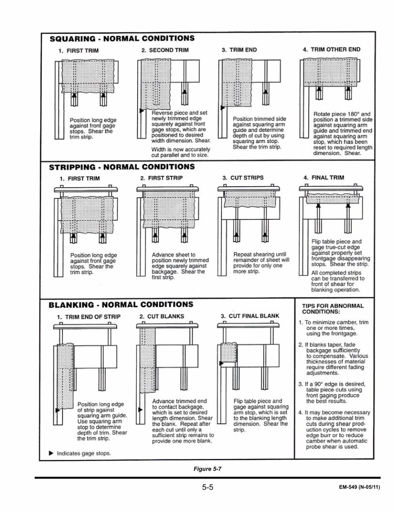
SQUARING BlANKS
This operation produces parts with opposite sides parallel, all corners square and all edges clean. The squaring arm with its gages and the backgage are usually used for these pieces as shown on Figure 5-7.
SQUARING lARGE SHEETS OR PlATES
Figure 5-7 illustrates the squaring operation, which requires use of the squaring arm with its gages and the front support arms with their gage stops.
STRIPPING
This is a shearing operation where many narrow pieces, usually less than 3” or 4” (76 or 102mm) wide, are sheared from a large sheet or plate. An example of stripping is
shown on Figure 5-7. These strips are usually cut using the backgage with a pair of frontgage stops set in the front support arms for an initial trim.
SHEARING NARROW WIDTHS
Extra precautions must be taken when shearing narrow pieces to make sure the clamping force is sufficient tohold the piece flat against the table during the cut.Thisis especially true when shearing material at or near the thickness capacity of the shear. If the clamping force is not sufficient,thematerialwillraiseoffthetableduringthecutand then re-clamp after the cut is complete. This creates a potential pinching hazard between the material and the table. Dull knives, excessive knife clearance, and improper holddown pressure can contribute to this problem. It is recommended that the following procedure be used when shearing narrow width material:
Use sharp knives.1.
Set the knife clearance to a minimum.2.
Make a test cut, exercising extreme caution, anticipating 3. that the material may raise off the table.
If material does raise, reposition along the table so at 4. least two holddowns are clamping the material. Another method is to provide an external clamping mechanism. For example, a work clamp bolted to dovetail slot in the squaring arm or the table. See Figure 5-3.
BlANKING
Ordinary blanks are made by shearing wide strips using the backgage and two sets of frontgage stops. The outer set of frontgage stops are set for making a trim cut, which should be at least as wide as the metal thickness. The backgage is set to the desired width of the blank and is used to shear all blanks except the last blank. This blank is sheared using the innersetoffrontgagestops.Afterthefirsttrimhasbeenmade, the material is fed against the backgage and strips are sheared until the original sheet or plate is so reduced in width that it cannot be fed against the backgage. Flip orrotate180°theremainingpieceandmakethefinaltrimusing the inner front gage stops. This leaves the last blank on the table with the scrap falling behind the shear. Quite often it may be desired to shear the ends of these blanks. This will normally require use of the squaring arm and its gages. See Figure 5-7.
5-5 EM-549 (N-05/11)
Figure 5-7

5-6EM-549 (N-05/11)
MAKING TRIANGUlAR GUSSETS
Production of gussets can be a hazardous operation if not done properly. There are two recommended procedures to follow when making gussets, either of which will allow them to be produced safely.
PROCEDURE #1 (See figure 5-8)Use a miter gage, light beam shearing gage, and the side gage or squaring arm bar.
Do not remove any guards from the shear and never place hands near or under the material during shearing - Injury could result.
Cutoffasufficientnumberofstripsorblankstogive1. the desired number of gussets. These strips should be as wide as a leg of the gusset is long.
Set the miter gage at the desired angle (usually 45°) to 2. the edge of the table. This gage must be positioned so that the strip will be centered under a holddown.
Feed the strip into the shear with one edge (side “A”) 3. against the miter gage until the corner of the strip away from the miter gage is right at the cutting edge of the lower knife. This position can be checked by using a light beam shearing gage.
Figure 5-8 - Triangular Gussets
Cycletheshear,makingthefirstcut.4.
Place the other edge (side “B”) of the strip against the 5. side gage or squaring arm.
Feed the strip into the shear until its beveled corner (on 6. side “A” away from the side gage or squaring arm) is directly over the cutting edge of the lower knife.
Cycle the shear making cut #2.7.
Repeat steps 3 through 5 as often as required.8.
IMPORTANT: CINCINNATI does not recommend making more than one cut per cycle.
PROCEDURE #2Use the backgage and a special tool similar to Figure 5-9. A light beam shearing gage could be helpful. The following procedure is for 45° gussets. The tool and setup would vary for other angles.
Cut material into strips or blanks with their width equal 1. to the length of a gusset leg.
Cut the strips or blanks into squares.2.
Set the backgage so that the counters or dials read the 3. same as the length of the side of the square multiplied by .707. For example, the backgage setting to shear a 6” (l52mm) square would be:
X = 6” (l52mm) times .707X = 4.242” (107.46mm)(X is back gage setting)
Make a tool similar to Figure 5-9. 4.
Figure 5-9 - Gusset Shearing Tool

5-7 EM-549 (N-05/11)
Note: Thickness “A” must be less than material thickness to permit holddown to firmly clamp the material.
Place this tool over one corner of the square blank 5. and feed the opposite corner into the shear under a holddown until it contacts the backgage angle.
Note: Repeated use of this technique of pushing the material into the backgage angle can eventually cause a groove to be worn into the face of the angle.
Be certain that the square blank and tool are centered under a holddown.
Square up the piece so the other two corners are at the 6. line-of-cut over the lower knife. The edge of the tool will be perpendicular to the knife and parallel to the side gage. Another way to line up the blank and tool is to scribe a line on the table perpendicular to the front edge of the table to show the proper location for the edge of the tool. This line must be positioned so the blank and tool will be directly under a holddown when the edge of tool is next to it.
Cycle the shear and the rear piece will fall off.7.
Use the tool to push the remaining piece through the 8. knives until it falls from the table.
SHEET SPlITTING
Material thickness guidelines have been established for splitting sheets where the back piece exceeds the backgage range. The maximum thickness for a 48” (1219mm) range backgage is 3/16” (.188”/4.763mm). The shear must be set on full length stroke and maximum capacity setting. The thickness is valid as long as the material shape allows the sheet to freely clear the backgage angle. The backgage system and the backgage angle in particular, are not designed to withstand forces associated with bending the material.
SlITTING
The gap frame design of a CINCINNATI SE Hydraulic Shear provides an easy method of shearing plates longer than the shear. The ram stroke is adjusted to prevent the knives crossing completely at the high (left) end. Turn the SHORT STROKE selector to the “RIGHT” position. Adjust the ram stroke by alternately adjusting the LENGTH adjustment knob and stroking the ram until the ram reverses at the desired point in its stroke. See Figure 5-10. Plate can then be slit in successive cuts by progressively moving it to the right through the throat. The backgage, frontgage, or a scribed line can be used to position material.
Figure 5-10 - Slitting
Thefirstcutshouldbeonlytwoorthreefeet(.6or.9meters)long so the back piece is not displaced down enough to interfere with the bottom of the housing gap when the end of the plate is passed through the right end. An optional slitting attachment can be attached to the right end of the table to support the plate during this operation.
See Figure 5-11. The backpiece width is limited by the depth of the housing gaps. Notching can also be done using this slitting feature.

5-8EM-549 (N-05/11)
Figure 5-11 - Slitting Operation

6-1 EM-549 (N-05/11)
SEcTiON 6 machiNE cONTrOlSMAIN ElECTRICAl ENClOSURE
The main electrical enclosure on CINCINNATI SE Hydraulic Shears is located on the outside of the left housing. See Figure 1-2. The main disconnect switch is on this enclosure. It disconnects all electrical power to the machine. There is never a need for the operator to open this enclosure. If the machine does not function properly, maintenancepersonnelshouldbenotified.
A ground connected light is mounted on the main electrical enclosure facing the front of the machine. The low voltage circuit is a grounded circuit. This is an internal chassis ground; it does not indicate that the machine is grounded. When the light is lit it indicates the ground is connected. It is a push-to-test light. If the light does not come on when the main disconnect is turned on, push it in to test it. If it does not come on, the bulb is burned out or it indicates a blown fuse. If the light does come on, it indicates that the ground wire is disconnected. In either case, contact maintenance personnel.
All of the operator controls, except for the power feed rolls, are located on the pedestal mounted operator control console. See Figure 1-1. The pedestal is connected to the main electrical enclosure with a flexible conduit. Thispermits moving the pedestal to the most convenient location. The Operator Control Console contains two control units, the Shear Control Center (Figure 6-1) and the Digital Gage Control. The Shear Control Center provides controls for the shear’s various functions, as well as manually selecting a position, The Digital Gage Control provides for automatic backgage positioning by means of a microcomputer.
OPERATOR CONTROl CONSOlE
Figure 6-1 - Operator Control Console
READY Light: When the light is on, it indicates the shear is ready to cycle. Stepping on the footswitch will start a cycle.The lightwill flash slowly if the shearmustcomplete a rake change before shearing. The light will flashrapidlyifthecontrolhasdetectedanerror.Ifthelight is off it indicates the shear is not ready to cycle for one or more of the following reasons:
The main disconnect is off.•The main drive motor is not running.•The OPERATOR CONTROLS selector is in the “OFF” •position.For the first cycle after starting main drive motor•the footswitch may not start a cycle. When the machine condition does not agree with MATERIAL THICKNESS, MATERIAL LENGTH, or GAGE UP - DOWN settings, stepping on the footswitch will activate these controls. The READY light will go off and the machine will adjust to agree with these settings.
MATERIAL THICKNESS Adjustment Knob: The MATERIAL THICKNESS knob adjusts the rake of the upper knife. The knob is graduated in mild steel thicknesses. To make a rake adjustment turn the knob to bring the mild steel thickness in-line with the indicator mark (the solid triangle at the 9:00 position). If shearing other than mild steel, set for the equivalent mild steel thicknessasspecifiedintheShear Capacities Bulletin PT-30491.
Never shear material with the knob set in the red portion. The “0” position is for maintenance only. failure to comply with this warning could result in machine damage, personal injury, or death.
Make sure everyone is clear of the machine before adjusting Material Thickness. If the OPERATOR CONTROlS selector is turned to the “ON” position and the MODE selector is not turned “Off”, the left end of the ram will move as soon as the knob is turned.
To avoid erratic ram motion, do not lower the rake unless the right cylinder is at the top of its stroke. This
6-2EM-549 (N-05/11)
is accomplished by setting the length adjustment for a full length cut. Refer to the following MATERIAL LENGTH adjustment knob instructions.
MATERIAL LENGTH Adjustment Knob: Adjusts the stroke of the shear ram. The graduations on the MATERIAL LENGTH adjustment knob are for the cut length in feet (or millimeters). To make a length adjustment, turn the knob to bring the desired length in line with the indicator mark. This adjustment automatically provides enough stroke for any rake setting.
It is possible to leave the length adjustment at the maximum setting. However, doing this will increase the cycle time of the shear.
The shear will not adjust for a longer length until the footswitch is activated.
The shear will not adjust for a shorter length until the machine is cycled, regardless of the MODE selector position. The ram will stop at the correct position for the shorter length on the return stroke.
There is another way of shearing short pieces at the right end of the shear. Set the SHORT STROKE selector at “LEFT”, the MATERIAL LENGTH selector at the maximum setting and the MODE selector on “SINGLE STROKE”. To minimize cycle time when shearing, release the footswitch when the cut is complete.
If the MATERIAL LENGTH adjustment knob is set incorrectly, such that the stroke of the ram is too short for the piece to be sheared, one of two things can happen:
With the SHORT STROKE selector in the “LEFT” •position, there will not be sufficient clearancebetween the knives at the right edge of the plate.
With the SHORT STROKE selector in the •“RIGHT” position, the ram will reverse before the cut is complete.
The MATERIAL THICKNESS and MATERIAL LENGTH adjustment controls are completely independent. Adjusting one does not require resetting the other.
REAR CORNER SUPPORT Selector (Optional): Refer to REAR CORNER SUPPORT in Section 8.
LIGHTS Pushbutton (Optional): The bracket mounted
row of lights is the light beam shearing gage, which provides a shadow line on the workpiece to indicate the line of cut. It allows shearing to a scribed line on the workpiece. The light beam shearing gage will turn on automatically when the main drive is started and will turn off automatically if the machine is idle for a long period of time. The pushbutton will toggle the lights on or off as desired. They can also be used to provide additional illumination to the table area.
BALL TRANSFERS Selector (Optional): This feature adds individual air chambers to each of the standard ball transfers in the shear table. The OFF - ON selector on the Shear Control Center permits raising or lowering them. With the selector switch in the “OFF” position, the ball transfers remain down below table level at all times. With the selector in the “ON” position, the ball transfers remain up until the footswitch is depressed. Depressing the footswitch to the intermediate position lowers the ball transfers, but does not start a shear cycle. This permits checking the plate alignment before making the shear cut, which is started by depressing the footswitch to its bottom position.
POWER KNIFE CLEARANCE Selector (Optional): Refer to POWER OPERATED KNIFE CLEARANCE in Section 8 and EM-465, Power Operated Knife Clearance.
MODE Selector: Operation of the shear is controlled by a four-position keylock MODE selector switch and one (or two) three-position footswitch(es). The four positions of the MODE selector switch are as follows:
“OFF” - In this position all controls which cause or allow ram motion are deactivated, including the footswitch, MATERIAL THICKNESS adjustment knob, and the MATERIAL LENGTH adjustment knob. When the MODE selector is turned off, the drive motor and pump will remain running.
“INCH” - With this position selected, the ram will move continuously whenever the footswitch is fully depressed. If the footswitch is raised to its mid or top position, ram motion will cease. Reactivation of the footswitch will start the ram moving again in the same direction as before. This mode is normally used for setup procedures and maintenance.
“SINGLE STROKE” - This is the recommended operating mode for production shearing. Fully depressing the footswitch will cause the ram to make one complete

6-3 EM-549 (N-05/11)
cycle, stopping at the top of the stroke. Fully releasing the footswitch during a stroke will immediately return the ram to its top position, regardless of the direction it had been moving. If the footswitch is released to its mid-position during the down stroke, the ram will stop and the holddowns remain clamped. Fully depressing the footswitch will cause continued downward travel.
“CONTINUOUS” - An operating mode where the ram will continue to cycle as long as the footswitch is held fully depressed. All other features of this mode are identical to those described for “SINGLE STROKE”. This mode is useful when stripping narrow widths of light gage material where it is not necessary to stop the ram at the top of the stroke to allow for feeding the material.
Most production shearing will be done using either the “SINGLE STROKE” or “CONTINUOUS” position, the advantage being that the operator can release the footswitch on the up stroke of the ram and the ram will continue to the top of the stroke and stop. Another feature of these positions is that the operator can release the footswitch as soon as the knife cuts through the material and the ram will immediately reverse and return to the top of its stroke. This eliminates changing the stroke limits for shearing a small quantity of narrow pieces at the right end or waiting for the ram to go through its complete stroke. See Figure 6-2.
Figure 6-2 - Footswitch Operation
Depressing the footswitch only to its mid position allows for independent operation of the holddowns in all operating modes. This feature is used for checking the material position when using the light beam shearing gage to shear to a scribed line. Release of the footswitch
returns the holddowns to their normal up position.
Depressing the footswitch to its full down position starts motion of the shear ram. Downward travel of the ram will continue only while the footswitch remains in this position, giving the operator total control during the cutting portion of the machine cycle.
FOOTSWITCH Selector (Optional): CINCINNATI Shears are usually operated by a single, guarded footswitch. A second footswitch can be provided which allows operation from either end of the shear, or both footswitches can be used to allow two operators to handle large sheets. This puts the shear in control of both people, preventing the ram from stroking until both footswitches are depressed. This option includes the extra footswitch and a selector switch that allows the operator to select “LEFT”, “RIGHT”, or “BOTH” footswitches. There is also an optional “AUTO. MODE” that is used with an automation machine.
“LEFT” / “RIGHT” - If the “LEFT” or “RIGHT” position is selected, only the selected footswitch is operative, the other footswitch is not. Depressing the selected footswitch will start a shear cycle as described earlier.
“BOTH” - In the “BOTH” position, both the left and right footswitches are active. Both footswitches must be fully depressed to start a shear cycle. If the ram is on its downward travel and either footswitch is released to the mid-position and the other remains fully depressed, the ram will stop. However, the holddowns will remain clamped. If one footswitch is in the fully released position and the other is in either the mid position or down position, the ram will stop and the holddowns will unclamp. In the “SINGLE STROKE” mode, after the ram has returned to the top of the stroke both footswitches must be fully released before another stroke can be made.
“AUTO. MODE” - When the shear is used in conjunction with an automation machine, the “RIGHT” footswitch position is replaced with Automatic “AUTO. MODE”. In this position, the shear can be cycled when initiated properly from the automation machine. Use caution when the footswitch selector is in “AUTO. MODE” because the shear cycle can be initiated from the automation machine without a footswitch being depressed by an operator. The “LEFT” position operates as mentioned above. The “BOTH” position requires both the left footswitch and the signal from the

6-4EM-549 (N-05/11)
automation machine to start a shear cycle.
SHORT STROKE Selector: The shear and the controls are best suited for shearing at the left end. However, the SHORT STROKE selector is provided to permit slitting and to shear short lengths on the right end for special reasons; for example, to even out knife wear.
In the “LEFT” position the ram will stroke between a fixed “DOWN” position and an adjustable “UP”position, which is set with the MATERIAL LENGTH adjustment knob.At the fixed “DOWN” position theknives will cross at the left end. At the adjustable “UP” position the knives will be open enough to shear a piece on the left end equal to the length setting on the MATERIAL LENGTH adjustment knob.
In the “RIGHT” position the ram will stroke between a fixed “UP” position and an adjustable “DOWN”position, which is set with the MATERIAL LENGTH adjustmentknob.Atthefixed“UP”positionthekniveswill be open enough to shear material at the right end.
OPERATOR CONTROLS Selector: This is a two-position keylock selector switch. In the “OFF” position all ram and backgage motion is prevented. Also the optional air-operated ball transfers and power feed rolls are inactive. The main drive motor and optional lights, oil heater, and air/oil heat exchanger are still active. The OPERATOR CONTROLS selector should be placed in the “OFF” position and the key removed any time that ram motion is to be prevented, such as when removing material from the rear of the machine. The “OFF” position should also be used when performing maintenance functions which require pump and motor to be running. When the OPERATOR CONTROLS selector is turned to the “ON” position, all operator controls are active.
GAGE DOWN - UP Selector: This is a three-position spring centered selector switch. The switch must be held in the “DOWN” position to move the gage down, and it must be held in the “UP” position to move the gage up. If the selector is released to the center position the gage will stop motion.
The gage will not move up unless the gage bar is moved to its fully retracted position. This is necessary to avoid a mechanical conflict between the gage bar and themotor when in the up position. To move the gage to the fully retracted position. Hold the GAGE UP-DOWN selector to the up position and press the START button on the DGC. This will move the gage. When the gage
has finished retracting, hold the selector in the “UP”position to raise the bar.
MAIN DRIVE START Pushbutton: To start the main drive motor depress the START pushbutton and hold for about three seconds. If the internal checks indicate that all components are functioning properly, the motor will start. The green light in the START pushbutton will light, indicating that the motor has started.
MAIN DRIVE STOP Pushbutton: When the red button is depressed all power to the motor is turned off. The motor and hydraulic pump will stop.
Make sure everyone is clear of the machine before turning the OPERATOR CONTROlS selector to the “ON” position. If the MODE selector is not turned to “Off”, ram motion may occur. To avoid this possibility, turn the MODE selector to “Off” before turning the OPERATOR CONTROlS selector to “ON”. Also, if the actual gage position (up or down) does not agree with the GAGE UP - DOWN selector position, the gage will move to the selected position. To avoid this movement, turn the gage selector to agree with the actual position.
DIGITAl GAGE CONTROl
The Digital Gage Control is a microprocessor control used for positioning backgages and (optional) frontgages on CINCINNATI Shears. It can be used for simple single cuts or for multiple shearing sequences of up to 99 steps. The control features incremental frontgage moves for easy programming of the frontgage and a frontgage back-off motion to prevent binding of the table piece. Up to 200 programs can be saved in the internal battery-backed memory. An optional communications interface can be providedtoallowofflinestorageonahostcomputer.Threecounters: stroke counter, batch counter, and production counter, are provided to keep track of parts produced. The counter values are retained even when power is off. Battery-backed RAM (Random Access Memory) retains all program values when power is off.
For more information on the Digital Gage Control, refer to the manual: Digital Gage Control II for Shears, EM-546.

7-1 EM-549 (N-05/11)
SEcTiON 7 OpEraTiONDAIlY START UPAt the beginning of a new shift, after every break, at the start of a new job, or when the machine is started after an extended off period (several hours or longer), the following procedure is recommended:
Check the reservoir oil level.1.
Turn the main disconnect switch on.2.
Depress the MAIN DRIVE START pushbutton.3.
Let the pump idle for a few minutes to warm the oil.4.
Check that the GROUND CONNECTED light is on.5.
Check that all required safety devices and procedures 6. are operating properly and are being used.
Make certain that the table, knife area, and rear 7. of machine are clear of tools, loose material, and personnel.
Turn the OPERATOR CONTROLS selector to the 8. “ON” position.
Turn the MATERIAL adjusting knob to the maximum 9. position.
Turn the LENGTH adjusting knob to the maximum 10. position.
Turn the MODE selector to the “SINGLE STROKE” 11. position.
Momentarily depress the footswitch. The ram may 12. adjust the rake or move to the top of the stroke.
Check the controls for proper operation.13.
Check the following for set up or the job to be run:14.
All controls are positioned correctly.•Knife clearance is correct.•Gages are set up correctly.•
POWER DOWNTo ensure that the shear is powered down in a safe and systematic way, the following procedure should be followed:
Turn the MODE selector to the “INCH” position.1.
Turn the OPERATOR CONTROLS selector to the 2. “ON” position.
Depress the footswitch and move the ram to the bottom 3. of the stroke.
Turn the MODE selector and OPERATOR CONTROLS 4. selector in the “OFF” position.
Depress the MAIN DRIVE - STOP pushbutton.5.
Turn the main disconnect switch off.6.
KNIfE ClEARANCETo minimize the shearing load and to yield high quality sheared edges (free of double shear and heavy edge burr), it is necessary to adjust the knife clearance on hydraulic shears for different materials, material thicknesses, and back piece depths.
On the CINCINNATI SE Series Hydraulic Shear, the knife clearance is easily changed and accurately set without jogging the ram and without changing the rake. With standardtableshims,therearefivedistinctpredeterminedclearances which can be used by positioning the shear table (including lower knife) to different positions with respect to the upper knife. The shear table is held snug against the top of the bed and housings by studs preset with double nuts. These do not require adjustment or changing when changing clearances. The inner position of the table (minimum knife clearance) is controlled by the inner table adjusting screws, which are preset at the factory and locked with jam nuts. They should not be changed except when changing knives. With the block on the bottom of the table firmly against the inner adjusting screw, theclearance is preset at its minimum value. These values are .005” (.13mm) on 4SE and 6SE series, .010” (.25mm) on 8SE and 10SE series, and .020” (.51mm) on 12SE series. Setting the inner adjusting screws and locking with the jam nuts prevents the knives from clashing.
USE Of TABlE SHIMS (Unless Equipped with Optional Power Operated Knife Clearance)
The hydraulic shear is supplied with captive table clearance shims located on the right and left side of the table to adjust knife clearance. See Figure 7-1. These shims are used in certain instances to get a better cut edge than can be obtained with the minimum knife clearance. Their use

7-2EM-549 (N-05/11)
can also significantly reduce the force required to shearmaterial. The determination of what shim to use, if any, for a particular job is largely a matter of operator experience. The following general guidelines will be helpful until the operator becomes familiar with the use of the shims. On narrow back pieces (trim cuts), a better sheared edge will generally be obtained with close knife clearances while on deep back pieces, a better edge will generally be obtained with wide knife clearances when cutting near capacity material.
Figure 7-1 - Table Shims, Legend Plate, and Table Adjusting Screw
There are two slotted, dual thickness shims and an identificationplateateachendofthetable.Theyarearrangedsotheletteratthetopoftheidentificationplateindicateswhich shim, if any, is in use. If the slot on the horizontal shim is visible, no shims are in use. If it is not visible, a shim is being used and the letter at the top indicates which one. The four shims are lettered “A” through “D”. “A” is the thickest and yields the greatest knife clearance - 15% of the rated maximum material thickness. The use of the table shims is shown on a legend plate attached to both housings. Figure 7-2 is a typical legend plate, and is for a 4SE Series shear. Other size machines have a similar legend plate. The legend plate recommends which letter shim to use for various thicknesses and materials. It recommends using no shim on narrow (trim cut) back pieces or on stainless steel. For material other than mild steel, it typically recommends a decrease in table shim. For example, for 3/8” (9.5mm) high strength steel the “C” table shim is recommended. Because of variation in material properties, the use of the next thinner shim may yield a more satisfactory edge condition. To change the shims, adjust the table so that the lower knife moves away from the upper knife. This is accomplished by turning the outer table adjusting screws
counterclockwise with the captive wrenches on each side of the machine. Insert the selected shim in the gap between the block on the bottom of the table and the inner adjusting screw. The outer table adjusting screw is turned clockwise until the shim is clamped in position. Use the same shim on both sides of the table. Do not overtighten as this may strip the threads in the table or distort the shims.
Figure 7-2 - Table Shim Legend Plate (4SE Series Shown)
There is one other very important fact to keep in mind when operating a hydraulic shear and changing knife clearance. It is a general assumption that a hydraulic shear is safe and cannot be harmed by overloads. This is true, as the main relief valve will dump and stop the ram if an attempt is made to shear material which is too thick for the rake set, or available, on the shear. However, the shear can be damaged by excessive spreading force (front-to-back) caused by excessive knife clearance on thinner material. The relief valve only controls the vertical shearing force and cannot control the resulting spreading force. This spreading force becomes excessive with wide knife clearance and thin material because it tends to fold the metal over instead of

7-3 EM-549 (N-05/11)
shearing it. This is especially true for stainless steel.
IMPORTANT: Always reset knife clearance when changing to thinner material to avoid damage to the shear.
GAGESAll CINCINNATI SE Hydraulic Shears are furnished with a backgage, side gage, and graduated scales as standard equipment. An optional front squaring arm, and front support arms are also available. The backgage and gage stops in the squaring arm or front support arms are movable stops against which the material to be sheared is positioned. These gages are set to control the size of sheared piece cutoff or remaining on the table. The side gage or the optional front squaring arm is used to guide and position one side of the material being sheared. The graduated scales in the table are a visual gage and are used to read the distance from the point of cut. The optional light beam shearing gage casts a sharp shadow line on the material at the shearing line, permitting shearing to a scribed line.
BACKGAGE
The standard backgage is located in the rear of the shear and its gaging face is parallel to the line of cut extending from housing to housing. This gage is used as a back stop to control the size of the piece cut off. It is moved by a motor and its position is adjusted by pushbuttons or the Digital Gage Control.
The backgage is used for the majority of all shearing and is generally used with a side gage or squaring arm. The recommended procedure for manually positioning the backgage using the pushbuttons on the Shear Control Center is to run it back beyond the desired setting and then move it slowly forward to that setting. The gage can be accurately positioned using the POSITION display on the Digital Gage Control. Final positioning is done by intermittently tapping the SLOW FORWARD pushbutton as it approaches the desired position. The backgage can also be positioned automatically by programming the Digital Gage Control, which is explained the Digital Gage Control II for Shears manual, EM-546. Using the side gage or the squaring arm as a guide, push the material to be sheared across the table and through the knives so it is solidly against the gaging surface (backgage angle) of the backgage and cannot be rocked against either gage. Do not use excessive force on the material that will compress the backgage compensating springs. The material is now in position to shear to size.
SIDE GAGE
This is a steel bar which can be mounted on the surface of the table near either end. Normally it is positioned at the left end. The functions of the side gage are:
To provide side support to the material during the cut.1.
To guide the material as it is being fed through the shear 2. so that it clears the inside surface of the housing.
To serve as a guide which is square with lower knife.3.
To position material so that it will not be located beyond 4. the end of the knife. The preferred location of the side gage is at the left end of the table. At this location, the side gage resists the tendency of the material to move during the cutting operation. When optional squaring arms are furnished, their preferred location is at the left end of the table. The side gage is then placed at the other end of the table.
GRADUATED SCAlES IN TABlE
There are two graduated scales in the table, one near each end, supplied as standard equipment. These scales are graduated in fractions of an inch, although other graduations are available. The scales can be set so they accurately indicate the distance from the cutting edge of the lower knife.
fRONTGAGE SUPPORT ARMS (Optional)There are many instances when use of the frontgage stops are helpful. The Shearing Operations in Figure 5-7 show how the frontgage stops can be used along with the side and backgages for trimming, stripping, and blanking. Also shown is the use of the front stops with the optional squaring arm to produce accurate re-squared blanks.
The support arms are bolted to the front of the shear table and their dovetail slots line-up with the slots in the shear table. Each slot has two or more disappearing or solid stops as shown in Figure 7-3. The stop is used to control the size of the cut off piece or the piece remaining on the table. The stops have two gaging surfaces approximately 1/4” (6mm) apart. One surface is used for trim cuts and the other surface for the final size cut after thematerialhas been rotated 180°. These stops are positioned manually using a scale, and are clamped in place by tightening their set screws.
When shearing very thin materials to a deep back piece width, they may sag enough to cause inaccurate width gaging by not properly contacting the face of the backgage

7-4EM-549 (N-05/11)
angle. The material may even sag so much that it completely misses the backgage angle. See Figure 7-4. Shearing heavier materials to a long back piece width may alsobedifficultsincetheoperatorcannotholdthematerialdown on the shear table. Some sheet support devices may not operate properly with very thin material due to sag, or with very heavy materials due to weight limitations. When these conditions exist, front gaging is the preferred method to use. See Figure 7-5. It may be necessary to get additional sets of these front stops so that multiple settings can be made.To set the standard two-step front stops, position the stops so the distance from the cutting edge of the table knife to the outer gaging face of the stops is the same as the desired finalsizeofthepiece.Thefirstcut(trim)shouldbemadewith an edge of the material against the inner gage faces. Afterthefirstcut,rotatethematerialonthetable180°andplace thefirstcutedgeagainst theoutergage faces,andmakethefinaltrim.Thiswillproduceafinishedpieceasaccurate as the gages were set. See Figure 7-6.
OPERATIONStart the shear as described in the beginning of this 1. section. Observe the operating rules and precautions in Section 5 - SETUP AND USE and the Safety Guidelines in Section 3 - SAFETY.
After startup of the shear, the display on the Digital 2. Gage Control will be flashing numeral eights. Thisindicates that the gage must be calibrated. Refer to ADJUSTING THE CALIBRATION in the Digital Gage Control II for Shears manual, EM-546, to calibrate the gage.
Enter a program for the gage positions. Refer to the 3. Digital Gage Control II for Shears manual, EM-546, for instructions on entering a new program in either MANUAL or AUTO mode.
After entering or selecting a program, place the material 4. on the table and push it against the backgage angle. Depress the footswitch to cycle the ram, shearing the material. A short time after the ram stops at the top of its stroke, the gage will move to the next programmed position. The POSITION display will change to show Step 2. The backgage will remain at this position until the cuts are completed for Step 2. The backgage will then move to the next programmed position and the shearing procedure is repeated until all steps in the program are completed.
Figure 7-3 - Front Gage Stops in Front Support Arms
Figure 7-4 - Shearing Thin Materials
Figure 7-5 - Front Gaging
Figure 7-6 - Front Gage Stops

8-1 EM-549 (N-05/11)
SEcTiON 8 OpTiONSThere are many options available for CINCINNATI SE Hydraulic Shears which increase productivity and/or improve accuracy.
ADDITIONAl fOOTSWITCHSE Shears are usually operated by a single, guarded footswitch. A second footswitch can be provided which allows operation from either end of the shear, or both footswitches can be used to allow two operators to handle large sheets. See FOOTSWITCH Selector description in Section 6 - MACHINE CONTROLS for a detailed control operation of the second footswitch.
AIR-OPERATED BAll TRANSfERSThe purpose of the ball transfer units is to make moving material across the table surface easier. This feature adds individual air chambers to each of the standard ball transfers in the table, permitting them to be raised or lowered. The control is a two position OFF - ON selector located on the SHEAR CONTROL CENTER. See Figure 6-1.
With the selector switch in the “OFF” position, the ball transfers remain down (below table level) at all times. With the selector switch in the “ON” position, the ball transfers remain up until the footswitch is depressed. Depressing the footswitch to the intermediate position lowers the ball transfers but does not start a shear cycle. This permits checking the plate alignment before making a shear cut, which is started by depressing the footswitch to its bottom position.
fRONT SUPPORT ARMSThese arms are bolted to the dovetail slot in the front face of the shear table. They provide support for large sheets of material. Adjustable position stops in the dovetail slot of the support arm provide for front gaging. Support arms are supplied with one disappearing slot. See Figure 7-3.
SQUARING ARMThe squaring arm can be mounted at either end of the table and is set square with the table knife. It is recommended that it be located at the left end. The material length is programmed into the control and positions the ram for shearing short pieces on the left end of the shear. (See SHEARING EXPLANATION in Section 5 - SETUP
AND USE). It is used to guide the material into the shear and is used when squaring material as shown in Figure 5-7. The squaring arm contains a graduated scale and is equipped with an adjustable gaging stop, either solid or swinging, to aid in front gaging.
fRONT GAGE STOPSFront gage stops are used in many front gaging operations, such as trimming, stripping, or blanking. See GAGES in Section 7 - OPERATION. The gage stops are manually set by measuring the distance from lower knife to the gaging surface of the stop.
Disappearing and solid stops are available for the table and front support arms. Both types have two gaging surfaces, onefora trimcutand theother for thefinishdimensioncut. The disappearing stop (Figure 7-3) pivots down to be flushwiththetabletoporturnsupforgaging.Itmayalsobe used in the special disappearing stop squaring arm. The solid stop (Figure 8-1) is also used in the dovetail slot of the table and front support arm.
Figure 8-1 - Front Support Arm Solid Stop
Swinging and solid stops are available for the squaring arm. These stops are also manually set and have one gaging surface. One swinging stop is furnished with the squaring arm. Multiple swinging stops (Figure 8-2) can be used to provide rapid gaging from the squaring arm. The sheet slips under stops not in use. The squaring arm solid stops (Figure 8-3) are designed for gaging heavy materials.

8-2EM-549 (N-05/11)
Figure 8-2 - Swinging Stops for Squaring Arm
Figure 8-3 - Solid Stop for Squaring Arm
Figure 8-4 - Power Front Feed Rolls
GRADUATED SCAlESStandard scales in the table and squaring arm are graduated in fractions every 1/16” and marked every 1”. Optional scales are available with decimal graduations every 0.050” and marked every 1”. Combination scales having inch and metric graduations are also available.
HOlDDOWN CUPSHolddown cups are pads that can be placed over the feet of the holddown plungers to minimize marking on soft or polished sheets. The cups are made of neoprene or plastic and are available for use on all 4SE and 6SE series shears.
HYDRAUlIC OIl HEATERThe oil heater is a thermostatically controlled unit to be installed on shears being placed in a very cold (below 50°F/10°C) location.
lIGHT BEAM SHEARING GAGEThis gage permits shearing to a scribed line on the material by casting a sharp shadow on the material at the shearing line. The scribed line and the shadow line are aligned, and then the shear is cycled. The light beam shearing gage will turn on automatically when the main drive is started and will turn off automatically if the machine is idle for a long period of time. The LIGHTS pushbutton will toggle the lights on or off as desired. The lights also provide additional illumination to the shear table area. Figure 1-1 shows the Light Beam Shearing Gage mounted in an SE shear.
POWER fRONT fEED ROllSThis option consists of two hydraulically driven, reversible, rubber coated rolls mounted on the front of the shear table. The feed rolls aid in loading large plates into the shear. See Figures 8-4 and 8-5. The controls consist of a free-standing floor mounted console containing sixpushbuttons; a FORWARD and REVERSE for the left roll, and a FORWARD and REVERSE for the right roll. This permits using the rolls together in either direction or individually in either direction. This option cannot be used with front support arms.
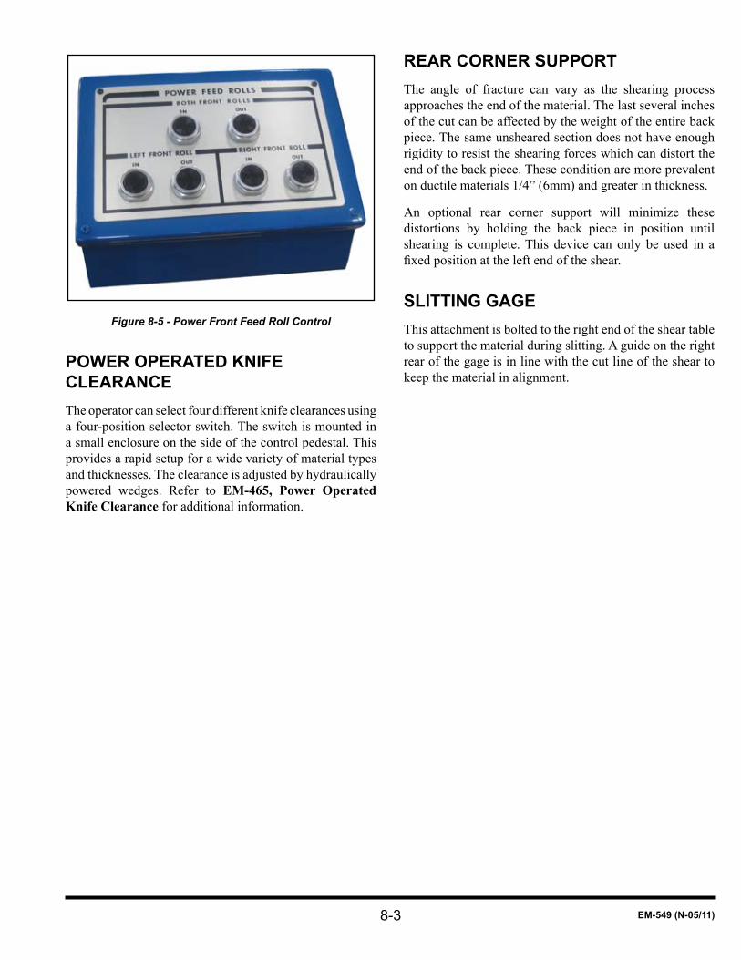
8-3 EM-549 (N-05/11)
Figure 8-5 - Power Front Feed Roll Control
POWER OPERATED KNIfE ClEARANCEThe operator can select four different knife clearances using a four-position selector switch. The switch is mounted in a small enclosure on the side of the control pedestal. This provides a rapid setup for a wide variety of material types and thicknesses. The clearance is adjusted by hydraulically powered wedges. Refer to EM-465, Power Operated Knife Clearance for additional information.
REAR CORNER SUPPORTThe angle of fracture can vary as the shearing process approaches the end of the material. The last several inches of the cut can be affected by the weight of the entire back piece. The same unsheared section does not have enough rigidity to resist the shearing forces which can distort the end of the back piece. These condition are more prevalent on ductile materials 1/4” (6mm) and greater in thickness.
An optional rear corner support will minimize these distortions by holding the back piece in position until shearing is complete. This device can only be used in a fixedpositionattheleftendoftheshear.
SlITTING GAGEThis attachment is bolted to the right end of the shear table to support the material during slitting. A guide on the right rear of the gage is in line with the cut line of the shear to keep the material in alignment.

8-4EM-549 (N-05/11)

9-1 EM-549 (N-05/11)
SEcTiON 9 maiNTENaNcE aNd adJuSTmENTSCHANGING OR ROTATING KNIVESShear knives have four cutting edges. They can be rotated until all four edges are dull At that time they must be reground or replaced with a new set. Refer to procedure on REGRINDING KNIVESforspecifications.
To rotate knives to a sharp cutting edge or change to a new or reground set of knives:
Two persons are required to handle the knife. Always wear gloves to protect hands while handling the knives.
Clear the area around the machine of scrap.1.
Run the backgage all the way to the rear.2.
Set the MODE selector to “INCH” position. Set the 3. SHORT STROKE selector to “LEFT” position.
Set the MATERIAL THICKNESS selector to “0”, 4. which sets the ram to zero rake.
Set the MATERIAL LENGTH selector to the maximum 5. length setting.
Stop the ram at the top of the stroke.6.
Turn the OPERATOR CONTROLS selector to the 7. “OFF” position and remove the key. Turn the MODE selector to the “OFF” position and remove key. Turn OFF all power to the machine and lock the electrical disconnect. Block the ram at both ends to prevent ram drift. Remove the gap guards. Place jacks under each end of the ram. Protect finished surfaces of the ramnose and the housing gap. Make sure there is room to the right of machine to move the upper knife left-to-right for removal.
Remove the end guards. Loosen the set screws in the 8. awareness barrier guard brackets and remove all the bars by sliding them out either end. It is not necessary to remove the guard brackets. The brackets which are directly above a knife pocket in the table should have one bolt removed. Then loosen the other bolt, swing the bracket aside, and tighten the bolt.
Clamp wooden strips, such as standard 2” x 4” (51 x 9. 102mm) lumber, on the table and under the upper knife to support it. See Figure 9-1.
Figure 9-1 - Clamp Wood Strip to Table
Remove the nuts and washers from the upper knife 10. bolts and push out bolts which are not in line with the holddown units.
Knife nuts and washers are removed from rear of shear and under ram brace. Do not reach between knives from front. Make sure power is off and controls are locked out.
Push the upper knife to the left as far as possible to 11. provide clearance for the remaining bolts. Remove the remaining knife bolts as shown in Figure 9-2.
Figure 9-2 - Knife Bolt Behind Holddown Unit
Slide upper knife from the machine through the housing 12. gap. Be sure to wear gloves.
Clean the knife and the knife seat in the ram.13.
Turn the knife and bring a sharp edge to the cutting 14. position. Slide it back into the shear over the blocks on the table.

9-2EM-549 (N-05/11)
Replace the bolts which were taken out at an angle. 15. Slide the knife into its normal position and insert the remaining knife bolts. Be sure the tongues of the knife bolt heads go into the keyways in the knife.
Replace the washers and nuts on the knife bolts and 16. tightenfingertight.
Hold the upper knife tight against the seat by prying up 17. with a long wooden lever at the center of the shear and tighten the center bolt. Repeat this prying operation while snugging-up each bolt. Work from the center to the right and then from the center to the left until all bolts are snugged up enough to hold the knife in position. Remove the wood strips installed in Step 9.
Remove the lower knife by removing the knife bolts, 18. washers, and nuts. Slide the lower knife out of the machine and place it on wooden blocks. Thoroughly clean the knife and the lower knife seats with a solvent, such as mineral spirits. Clean, but do not disturb, the locationoftheknifeshims.Useanoilstoneorfiletoremove any nicks or burrs from the knife seat.
Note: If replacing knives with a new or reground set, refer to procedure for SHIMMING THE LOWER KNIFE.
If rotating existing knives to a sharp cutting edge, proceed to Step 19.
Inspect the knife shims and pins. Replace any damaged 19. shims and bent or missing pins.
Lubricate the knife, knife seat, and shims with a light 20. machine oil.
Clean and inspect all knife bolts, nuts, and washers:21.
Run the nuts on the knife bolts to ensure the threads are notdamaged.Ifnecessary,handfitorreplaceboltsandnuts. Any nut with rounded corners must be replaced.
Turn the lower knife over and replace it in the shear 22. with a sharp edge in the cutting position.
Install all knife bolts, washers, and nuts. Be sure the 23. tongues of the knife bolt heads go into the keyways in the knife. Snug up nuts enough to hold knife in position. Do not tighten. Remove jacks from under ram (installed in Step 7).
Restart the machine and turn MATERIAL THICKNESS 24. selector clockwise, increasing rake of the ram.
Move the table to increase knife clearance as 25.
described in ADJUSTING MINIMUM KNIFE CLEARANCE.
Position wood wedges between the knives next to 26. every other holddown unit for seating the knives. The wedges can be cut from standard 2” x 4” (51 x 102mm) lumber. See Figure 9-3.
These wedges must be snug between the knives. It is not necessary to drive them tight.
Figure 9-3 - Knife Seating Wedges
Turn the MODE selector to the “INCH” position and 27. turn the OPERATOR CONTROLS selector to the “ON” position. Use the footswitch to slowly inch the ram down until the force on the wood wedges has seated the knives.
Turn the OPERATOR CONTROLS selector to the 28. “OFF” position and remove the key. Stop the main drive motor and lockout the disconnect switch.
Tighten all upper and lower knife bolt nuts to 29. approximately the torque shown in Table 9-1.
BOlT DIA.INCHES
TORQUEft-lbs (Nm)
WRENCH lENGTH INCHES (mm)
5/8 175 (237) 12 (305)
3/4 300 (407) 24 (610)
1 680 (922) 48 (1220)
TABLE 9-1 - Knife Bolt Torques
Be careful not to slip or fall when tightening knife bolts. The wrench can slip off rounded corner nuts or break.
IMPORTANT: Do not use the long handle wrench supplied with the shear. This wrench is to be used only for adjusting table nuts to achieve knife clearance.
Turn the MODE selector to the “INCH” position, 30. turn the OPERATOR CONTROLS selector to the
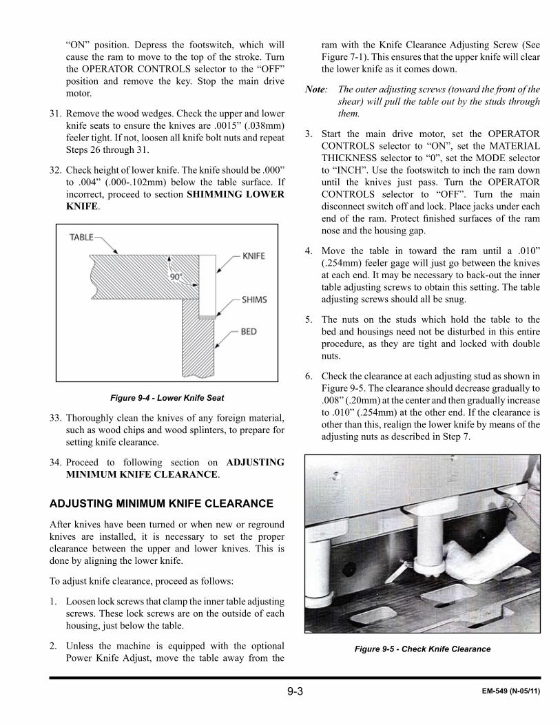
9-3 EM-549 (N-05/11)
“ON” position. Depress the footswitch, which will cause the ram to move to the top of the stroke. Turn the OPERATOR CONTROLS selector to the “OFF” position and remove the key. Stop the main drive motor.
Remove the wood wedges. Check the upper and lower 31. knife seats to ensure the knives are .0015” (.038mm) feeler tight. If not, loosen all knife bolt nuts and repeat Steps 26 through 31.
Check height of lower knife. The knife should be .000” 32. to .004” (.000-.102mm) below the table surface. If incorrect, proceed to section SHIMMING LOWER KNIFE.
Figure 9-4 - Lower Knife Seat
Thoroughly clean the knives of any foreign material, 33. such as wood chips and wood splinters, to prepare for setting knife clearance.
Proceed to following section on 34. ADJUSTING MINIMUM KNIFE CLEARANCE.
ADJUSTING MINIMUM KNIfE ClEARANCE
After knives have been turned or when new or reground knives are installed, it is necessary to set the proper clearance between the upper and lower knives. This is done by aligning the lower knife.
To adjust knife clearance, proceed as follows:
Loosen lock screws that clamp the inner table adjusting 1. screws. These lock screws are on the outside of each housing, just below the table.
Unless the machine is equipped with the optional 2. Power Knife Adjust, move the table away from the
ram with the Knife Clearance Adjusting Screw (See Figure 7-1). This ensures that the upper knife will clear the lower knife as it comes down.
Note: The outer adjusting screws (toward the front of the shear) will pull the table out by the studs through them.
Start the main drive motor, set the OPERATOR 3. CONTROLS selector to “ON”, set the MATERIAL THICKNESS selector to “0”, set the MODE selector to “INCH”. Use the footswitch to inch the ram down until the knives just pass. Turn the OPERATOR CONTROLS selector to “OFF”. Turn the main disconnect switch off and lock. Place jacks under each end of the ram. Protect finished surfaces of the ramnose and the housing gap.
Move the table in toward the ram until a .010” 4. (.254mm) feeler gage will just go between the knives at each end. It may be necessary to back-out the inner table adjusting screws to obtain this setting. The table adjusting screws should all be snug.
The nuts on the studs which hold the table to the 5. bed and housings need not be disturbed in this entire procedure, as they are tight and locked with double nuts.
Check the clearance at each adjusting stud as shown in 6. Figure 9-5. The clearance should decrease gradually to .008” (.20mm) at the center and then gradually increase to .010” (.254mm) at the other end. If the clearance is other than this, realign the lower knife by means of the adjusting nuts as described in Step 7.
Figure 9-5 - Check Knife Clearance
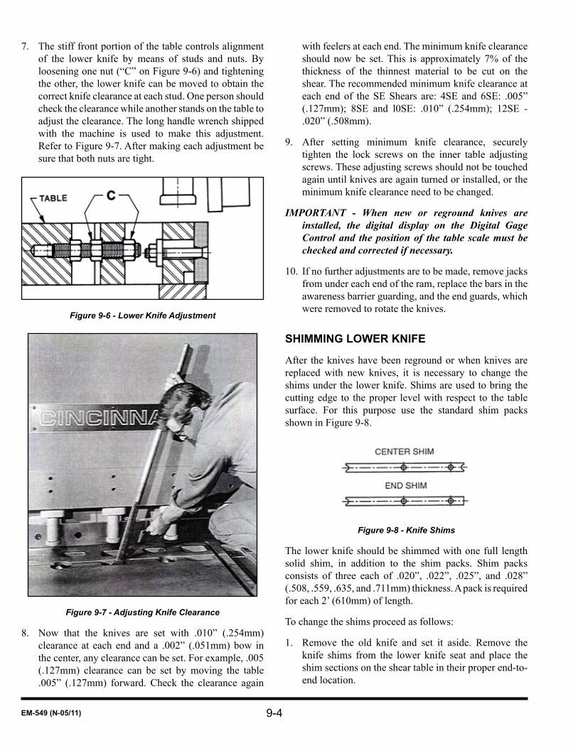
9-4EM-549 (N-05/11)
The stiff front portion of the table controls alignment 7. of the lower knife by means of studs and nuts. By loosening one nut (“C” on Figure 9-6) and tightening the other, the lower knife can be moved to obtain the correct knife clearance at each stud. One person should check the clearance while another stands on the table to adjust the clearance. The long handle wrench shipped with the machine is used to make this adjustment. Refer to Figure 9-7. After making each adjustment be sure that both nuts are tight.
Figure 9-6 - Lower Knife Adjustment
Figure 9-7 - Adjusting Knife Clearance
Now that the knives are set with .010” (.254mm) 8. clearance at each end and a .002” (.051mm) bow in the center, any clearance can be set. For example, .005 (.127mm) clearance can be set by moving the table .005” (.127mm) forward. Check the clearance again
with feelers at each end. The minimum knife clearance should now be set. This is approximately 7% of the thickness of the thinnest material to be cut on the shear. The recommended minimum knife clearance at each end of the SE Shears are: 4SE and 6SE: .005” (.127mm); 8SE and l0SE: .010” (.254mm); 12SE - .020” (.508mm).
After setting minimum knife clearance, securely 9. tighten the lock screws on the inner table adjusting screws. These adjusting screws should not be touched again until knives are again turned or installed, or the minimum knife clearance need to be changed.
IMPORTANT - When new or reground knives are installed, the digital display on the Digital Gage Control and the position of the table scale must be checked and corrected if necessary.
If no further adjustments are to be made, remove jacks 10. from under each end of the ram, replace the bars in the awareness barrier guarding, and the end guards, which were removed to rotate the knives.
SHIMMING lOWER KNIfE
After the knives have been reground or when knives are replaced with new knives, it is necessary to change the shims under the lower knife. Shims are used to bring the cutting edge to the proper level with respect to the table surface. For this purpose use the standard shim packs shown in Figure 9-8.
Figure 9-8 - Knife Shims
The lower knife should be shimmed with one full length solid shim, in addition to the shim packs. Shim packs consists of three each of .020”, .022”, .025”, and .028” (.508, .559, .635, and .711mm) thickness. A pack is required for each 2’ (610mm) of length.
To change the shims proceed as follows:
Remove the old knife and set it aside. Remove the 1. knife shims from the lower knife seat and place the shim sections on the shear table in their proper end-to-end location.

9-5 EM-549 (N-05/11)
Clean and inspect each stack of shims. Discard any 2. damaged shims and replace them with new shims of the same thickness.
Shims may have sharp edges. Protect the hands from cuts.
Remove and inspect the pins which retain the knife 3. shims in the lower knife seat. Replace all damaged or broken pins. Do not reinstall pins at this time.
Clean and lightly lubricate the lower knife seat with a 4. light machine oil.
Note: If shear has a full length shim, clean shim, remove any burrs and place it on the knife seat.
Clean the new or reground knife and place it on the full 5. length shim or knife seat.
Turn on power to the shear and run the backgage angle 6. forward far enough to hold the knife in the knife seat. Turn off the OPERATOR CONTROLS and the main disconnect switch and remove the keys.
Place the knife shims, removed in Step 1 on top of the 7. knife.Addorremoveshimsuntileachsectionisflushto slightly above the table top.
IMPORTANT: It may be necessary to use two shim packs for each section. If additional shims are required, CINCINNATI recommends standard shim packs as shown in Figure 9-8.
Compress the shims as shown in Figure 9-9 by moving 8. the wedge block toward the knife. Check thickness of the shim pack with a scale as shown in, Figure 9-10. Shears have a 90° knife seat. The knife should be .000”-.004” (.000-.102mm) below the top surface of the table. If necessary, add or remove shims to obtain the correct shim pack thickness.
Repeat Step 8 using the holddown at the center of each 9. shim pack. There must not be a difference in thickness of more than .003” (.076mm) between adjacent stacks of shims.
Place all unused shims in their proper envelopes. 10.
Place the shim stacks along the table in their proper 11. end-to-end location.
Figure 9-9 - Compress Shims
Figure 9-10 - Check Shim Pack Thickness
Turn on power to the shear and position the backgage 12. at maximum gage position. Turn the OPERATOR CONTROLS selector to “OFF” position and remove the key. Remove the knife from the knife seat and place it on wood blocks away from the immediate area.
Place shim stacks on the knife seat. The thickest shim 13. must be on top. If the shear has a full-length shim, place it on top of the shim stacks.
Adjust and install the shim pins. They are adjusted by 14. means of a set screw in one end of the pin. The pins must be adjusted so the end of the pin is just below the top of the shim stacks when the shims are compressed. The screws are self-locking. The screw pin units should

9-6EM-549 (N-05/11)
beinstalledscrewendfirst,withthepinonthetop.Amagnet could be helpful when removing the pins for adjustment.
Carefully place the lower knife on the shims. Use care 15. to not disturb the shims.
Proceed with Step 23 in the section 16. CHANGING OR ROTATING KNIVES.
IMPORTANT: Do not shim under upper knives. No means are provided to retain shims, so they may come out. This can cause knives to clash or even shatter.
REGRINDING KNIVESShear knives must be ground carefully to give good results. CINCINNATI recommends sending knives to a shear knife manufacturer for regrinding. They are experienced in the care and handling of knives. They also have the proper equipment to obtain an accurate grind.
CINCINNATI INCORPORATED offers this grinding service. For more information contact the Parts Department.
When returning knives for grinding to anyone other than CINCINNATI INCORPORATED, specify the following grinding limits;
GRINDING LIMITS
WIDTH: Parallel within .005” (.127mm) from end-to-end.
THICKNESS: Parallel within .003” (.076mm) from end-to-end.
No variation greater than .001” (.025mm) within any 12” (305mm) of length.
Knives may be reground a number of times within these limits until knives reach the minimum knife size.
SURFACE FINISH: 16 micro inch
MINIMUM KNIFE SIZE
SIZE - NEW KNIfEINCHES (mm)
MINIMUM GRIND DIMENSIONINCHES (mm)
1.0 x 4.0 (25.4 x 101.6) 0.75 x 3.625 (19.1 x 92.1)
1.125 x 5.0 (28.6 x 127) 0.875 x 4.625 (22.2 x 117.5)
1.5 x 5.5 (38.1 x 139.7) 1.25 x 5.125 (28.6 x 130.18)
1.75 x 6.5 (44.45 x 165.1) 1.50 x 6.000 (38.1 x 152.40)
TABlE 9-2 - Minimum Knife Size
ADJUSTING BACKGAGE ANGlE PARAllElISMIt may become necessary to adjust backgage angle parallel to the lower knife. A properly adjusted backgage angle should be straight or approximately .002” (.05mm) concave (hollow) in the center. This will help to ensure solid contact between the edge of the sheet or plate at two points on the gaging surface of the backgage angle. Consistent gaging cannot be obtained unless the angle is slightly concave. Conversely, gaging with an angle bowed toward the operator gives contact at only one point. This condition allows the operator to rock the sheet from side-to-side and the results will not be consistent.
To adjust the backgage angle:
Check for parallelism:1.
Position the backgage angle at 2.00” (50.8mm).a.
Make a test cut on a full length piece of material. b. Do not exceed the machine’s maximum material thickness capacity or cut below the machine’s minimum material thickness capacity.
Measure the part with vernier calipers or c. micrometers. Record these dimensions for later reference if the cut piece is not parallel.
Place the OPERATOR CONTROLS selector in the 2. “OFF” position and remove the key.
Remove the end guards and the awareness barrier 3. guard bars if not already removed. See CHANGING OR ROTATING KNIVES.
Check the backgage angle for parallelism to the lower 4. knife at each end. Place a 1” (25.4mm) gage block between backgage angle and the lower knife, flushwith the top of the knife. Use a feeler gage with this gage block to determine the backgage position.
Note: A gage block (Figure 9-11) with at least a 6” (150mm) handle must be used to keep hands and fingers as far from the cutting edge of the knife as possible.
If the gage is not parallel to lower knife within .002” 5. (.05mm), adjustments must be made.
Adjust the backgage angle:6.
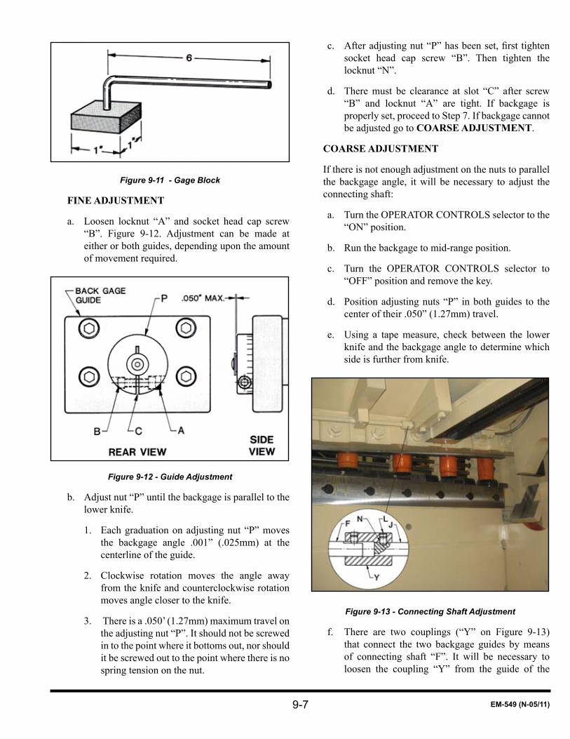
9-7 EM-549 (N-05/11)
Figure 9-11 - Gage Block
FINE ADJUSTMENT
Loosen locknut “A” and socket head cap screw a. “B”. Figure 9-12. Adjustment can be made at either or both guides, depending upon the amount of movement required.
Figure 9-12 - Guide Adjustment
Adjust nut “P” until the backgage is parallel to the b. lower knife.
Each graduation on adjusting nut “P” moves 1. the backgage angle .001” (.025mm) at the centerline of the guide.
Clockwise rotation moves the angle away 2. from the knife and counterclockwise rotation moves angle closer to the knife.
There is a .050’ (1.27mm) maximum travel on 3. the adjusting nut “P”. It should not be screwed in to the point where it bottoms out, nor should it be screwed out to the point where there is no spring tension on the nut.
c. Afteradjustingnut“P”hasbeenset,firsttightensocket head cap screw “B”. Then tighten the locknut “N”.
There must be clearance at slot “C” after screw d. “B” and locknut “A” are tight. If backgage is properly set, proceed to Step 7. If backgage cannot be adjusted go to COARSE ADJUSTMENT.
COARSE ADJUSTMENT
If there is not enough adjustment on the nuts to parallel the backgage angle, it will be necessary to adjust the connecting shaft:
Turn the OPERATOR CONTROLS selector to the a. “ON” position.
Run the backgage to mid-range position.b.
Turn the OPERATOR CONTROLS selector to c. “OFF” position and remove the key.
Position adjusting nuts “P” in both guides to the d. center of their .050” (1.27mm) travel.
Using a tape measure, check between the lower e. knife and the backgage angle to determine which side is further from knife.
Figure 9-13 - Connecting Shaft Adjustment
There are two couplings (“Y” on Figure 9-13) f. that connect the two backgage guides by means of connecting shaft “F”. It will be necessary to loosen the coupling “Y” from the guide of the

9-8EM-549 (N-05/11)
furthest side, as found in Step “E”. This will allow the guide screws to be rotated independently from each other.
Remove the lock screw “L” and socket set screw g. “N”. Remove the coupling to the backgage encoder if necessary. Wormshaft “J” can now be rotated.
Turn wormshaft “J” clockwise, looking at shaft h. from left end of shear, to make backgage angle move closer to lower knife. One rotation of wormshaft “J” will move the angle about 1/8” (3.18mm).
g. Again measure to see if the left and right ends of the angle are within 1/32” (.79mm) of each other. Continue to rotate wormshaft “J” until this dimension is reached.
h. Before installing socket set screw “N”, make sure its hole lines-up with relief drilled In wormshaft “J”. This is necessary to prevent coupling “Y” from slipping.
i. Install socket set screw “N” and then lock screw “L”. Re-couple backgage to encoder if it was uncoupled.
j. Coarse Adjustment is now complete. To make the Fine Adjustment, turn OPERATOR CONTROLS selector to “ON” position.
k. Run backgage in to 1-1/64” (or 1.016” or 25.8mm) dimension. Turn OPERATOR CONTROLS selector to “OFF” position and remove the key.
l. Repeat Step 4 to check parallelism and Step 6 to fineadjustbackgageangle.
7. The hollow in the center of solid angles may now be checked with a gage block. Use the special gage block describedinStep4.Placethegageblockflushwithtopof lower knife and against the backgage angle. Measure the distance between the gage block and lower knife with a feeler gage.
8. The backgage angle is set straight or hollow by adjusting bolt(s) “1”. Figure 9-14. There will be one or two adjustments depending on the length of the shear.
To make the solid backgage angle hollow, loosen outside nut and tighten inside nut. After correct setting has been made, tighten the outside nuts.
9. Reinstall awareness barrier and end guarding.
10. Turn OPERATOR CONTROLS selector to the “ON” position. ,
11. Run the backgage towards the rear of shear. Then move it forward to 1.000” (25.4mm).
Backgage Angle Adjustment Bolt1.
Figure 9-14 - Backgage Angle Adjustment
11. Make a trim cut on a full length piece of material. Do not exceed the machine’s maximum material thickness capacity or cut below the machine’s minimum material thickness capacity.
12. Position cut edge of sheet against backgage angle and make a cut. This piece will be used for measurement.
13. Measure the piece with vernier calipers or micrometer at each end.
14. If the cut piece does not measure within .005” (.127mm) end-to-end, the backgage is not parallel to the lower knife. Repeat the adjustment procedure beginning at Step 2.
15. After the backgage angle has been adjusted, it may be necessary to reset the backgage encoder. Refer to the following instructions on CALIBRATING BACKGAGE POSITION.
CAlIBRATING BACKGAGE POSITION
When the shear knives are turned, reground, or replaced with new knives, the distance from the cutting line to the face of the backgage angle will likely change. This change will also occur when resetting knife clearance. Refer to Digital Gage Control II manual, EM-546, for instructions on calibrating the backgage position.

9-9 EM-549 (N-05/11)
SQUARING ARM (OPTIONAl) ADJUSTMENT
A properly adjusted squaring arm must be level in relation to the shear table and perpendicular to lower knife over the length of the squaring arm. If the squaring arm will not allow blanks to be sheared within 1/32” (.81mmj across the diagonals, the squaring arm must be adjusted. If the gaging surface on the side of the squaring arm bar is not flat,thebarmustbereplacedorre-machined,
To check squaring arm alignment:
Check the level of squaring arm left-to-right and front-1. to-back as shown in Figure 9-15. Adjust the level as required.
Trim a full length sheet, preferably as long as the 2. squaring arm or the maximum length of the shear. Do not exceed the machine’s maximum material thickness capacity. Trim several times to get the camber to a minimum.
Place sheared edge of the material against gaging 3. surface of squaring arm bar.
Figure 9-15 - Leveling squaring arm
To adjust squaring arm alignment:
The sheet lays on table and against the squaring arm 4. bar as shown in Figure 9-18,
Loosen or remove anchor bolts for the squaring a. arm support leg. Loosen the bolts which fasten the squaring arm gusset to the table and the squaring arm guide. Move the squaring arm guide to the left as shown in Figure 9-16 until the sheared edge is tight against the squaring arm bar full length. Remove the full length sheet. If possible, reinstall and tighten the support leg anchor bolts. If new anchors for bolts are required, do not install at this time.
Re-level squaring arm guide as described in Step b. 1. Shear both edges of another piece of material to obtain a 36” (914mm) width. Place one sheared edge against the squaring arm bar and make a trim cut. Turn the sheet over, keeping the same edge against the squaring arm bar, and shear the other end to obtain a piece about 40” (1016mm) long.
Measure the distances Ll and L2 shown in Figure c. 9-18 with a tape measure. If they are not the same length, loosen front socket head screw “A” in Figure 9-17 and either set screw “B” or “C”. If Ll is longer, loosen screw “C” and tighten screw “B” to move the squaring arm bar towards the sheet. If L2 is longer, loosen screw “B” and tighten screw “C” to move squaring arm bar away from the sheet. Tighten screw “A” and either screw “B” or “C”.
Keep the same sheared edge against the squaring d. arm bar and trim both ends as in Step C, Re-measure distances Ll and L2. If necessary, repeat adjustments (Step D) until distances Ll and L2 are the same length within 3/64” (1.19mm) on a 36” x 36” (914 x 914mm) blank. This is the same as having the diagonals the same length within 1/32” (.813mm).
Place the full length sheet (removed in Step 4-A) e. with the sheared edge against the squaring arm bar. If necessary, move outer end of squaring arm to obtain full length contact on the squaring arm bar.
The squaring arm support leg anchor bolts must be loosened or removed to move the outer end of the squaring arm. After full length contact is obtained, install the support leg anchor bolts. If necessary, place shims between the squaring arm gusset and the table and/or guide. See Figure 9-19. Securely tighten bolts for the gusset. If necessary, shim between squaring arm guide and the table and securely tighten the nuts. Check the contact between the sheared edge of the full length sheet and the squaring arm bar. Repeat this step if required.
Sheet lays on the table and against the squaring arm 5. bar as shown on Figure 9-20. Use the procedure outlined under Step 4, except the initial movement of the squaring arm is to the right as shown on Figure 9-20.

9-10EM-549 (N-05/11)
Figure 9-16 - Align Squaring Arm Guide and Bar
Figure 9-17 - Bar Adjusting Screws
Figure 9-18 - Fine Adjust Squaring Arm Bar
Figure 9-19 - Shim Gusset
Figure 9-20 - Move Squaring Arm Guide and Bar
Figure 9-21 - Adjust Squaring Arm Bar
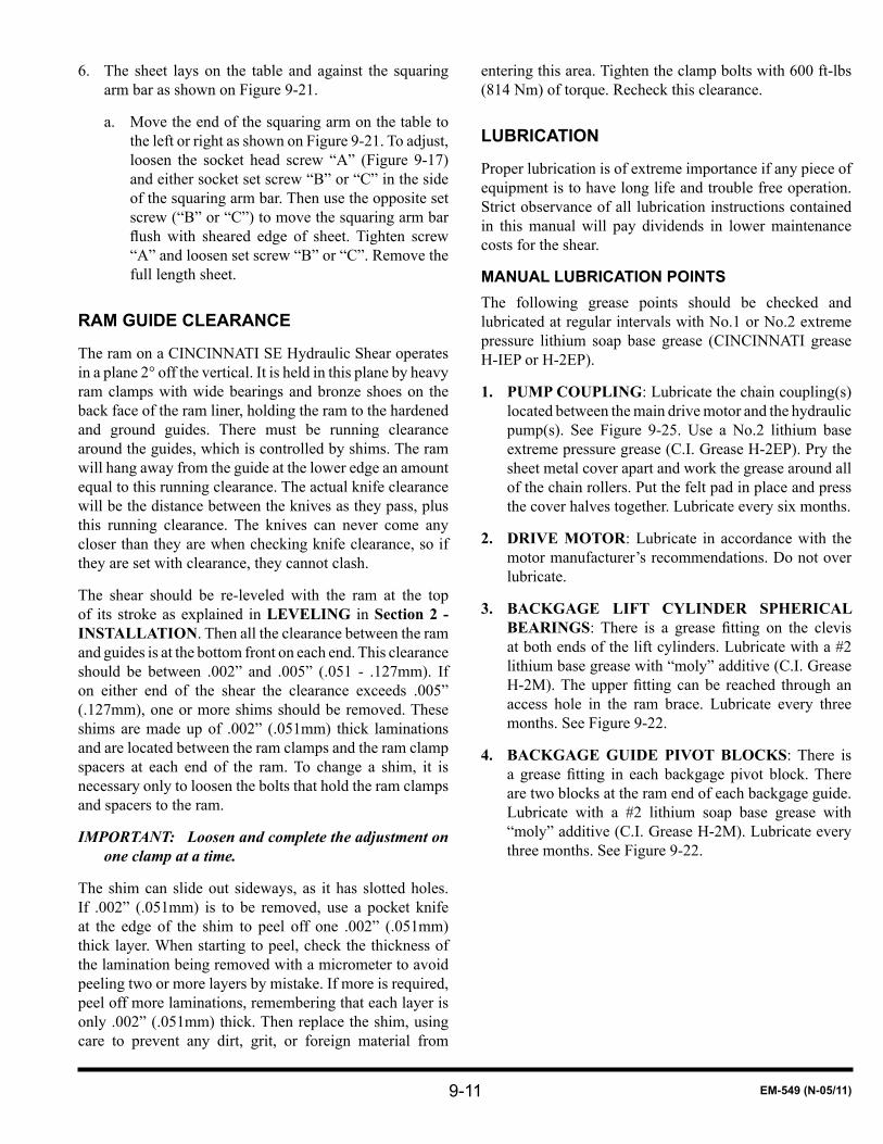
9-11 EM-549 (N-05/11)
The sheet lays on the table and against the squaring 6. arm bar as shown on Figure 9-21.
Move the end of the squaring arm on the table to a. the left or right as shown on Figure 9-21. To adjust, loosen the socket head screw “A” (Figure 9-17) and either socket set screw “B” or “C” in the side of the squaring arm bar. Then use the opposite set screw (“B” or “C”) to move the squaring arm bar flushwith sheared edge of sheet. Tighten screw“A” and loosen set screw “B” or “C”. Remove the full length sheet.
RAM GUIDE ClEARANCE
The ram on a CINCINNATI SE Hydraulic Shear operates in a plane 2° off the vertical. It is held in this plane by heavy ram clamps with wide bearings and bronze shoes on the back face of the ram liner, holding the ram to the hardened and ground guides. There must be running clearance around the guides, which is controlled by shims. The ram will hang away from the guide at the lower edge an amount equal to this running clearance. The actual knife clearance will be the distance between the knives as they pass, plus this running clearance. The knives can never come any closer than they are when checking knife clearance, so if they are set with clearance, they cannot clash.
The shear should be re-leveled with the ram at the top of its stroke as explained in LEVELING in Section 2 - INSTALLATION. Then all the clearance between the ram and guides is at the bottom front on each end. This clearance should be between .002” and .005” (.051 - .127mm). If on either end of the shear the clearance exceeds .005” (.127mm), one or more shims should be removed. These shims are made up of .002” (.051mm) thick laminations and are located between the ram clamps and the ram clamp spacers at each end of the ram. To change a shim, it is necessary only to loosen the bolts that hold the ram clamps and spacers to the ram.
IMPORTANT: Loosen and complete the adjustment on one clamp at a time.
The shim can slide out sideways, as it has slotted holes. If .002” (.051mm) is to be removed, use a pocket knife at the edge of the shim to peel off one .002” (.051mm) thick layer. When starting to peel, check the thickness of the lamination being removed with a micrometer to avoid peeling two or more layers by mistake. If more is required, peel off more laminations, remembering that each layer is only .002” (.051mm) thick. Then replace the shim, using care to prevent any dirt, grit, or foreign material from
entering this area. Tighten the clamp bolts with 600 ft-lbs (814 Nm) of torque. Recheck this clearance.
lUBRICATION
Proper lubrication is of extreme importance if any piece of equipment is to have long life and trouble free operation. Strict observance of all lubrication instructions contained in this manual will pay dividends in lower maintenance costs for the shear.
MANUAl lUBRICATION POINTSThe following grease points should be checked and lubricated at regular intervals with No.1 or No.2 extreme pressure lithium soap base grease (CINCINNATI grease H-IEP or H-2EP).
PUMP COUPLING1. : Lubricate the chain coupling(s) located between the main drive motor and the hydraulic pump(s). See Figure 9-25. Use a No.2 lithium base extreme pressure grease (C.I. Grease H-2EP). Pry the sheet metal cover apart and work the grease around all of the chain rollers. Put the felt pad in place and press the cover halves together. Lubricate every six months.
DRIVE MOTOR2. : Lubricate in accordance with the motor manufacturer’s recommendations. Do not over lubricate.
BACKGAGE LIFT CYLINDER SPHERICAL 3. BEARINGS: There is a grease fitting on the clevisat both ends of the lift cylinders. Lubricate with a #2 lithium base grease with “moly” additive (C.I. Grease H-2M).Theupperfittingcanbe reached throughanaccess hole in the ram brace. Lubricate every three months. See Figure 9-22.
BACKGAGE GUIDE PIVOT BLOCKS4. : There is a greasefitting in each backgage pivot block.Thereare two blocks at the ram end of each backgage guide. Lubricate with a #2 lithium soap base grease with “moly” additive (C.I. Grease H-2M). Lubricate every three months. See Figure 9-22.
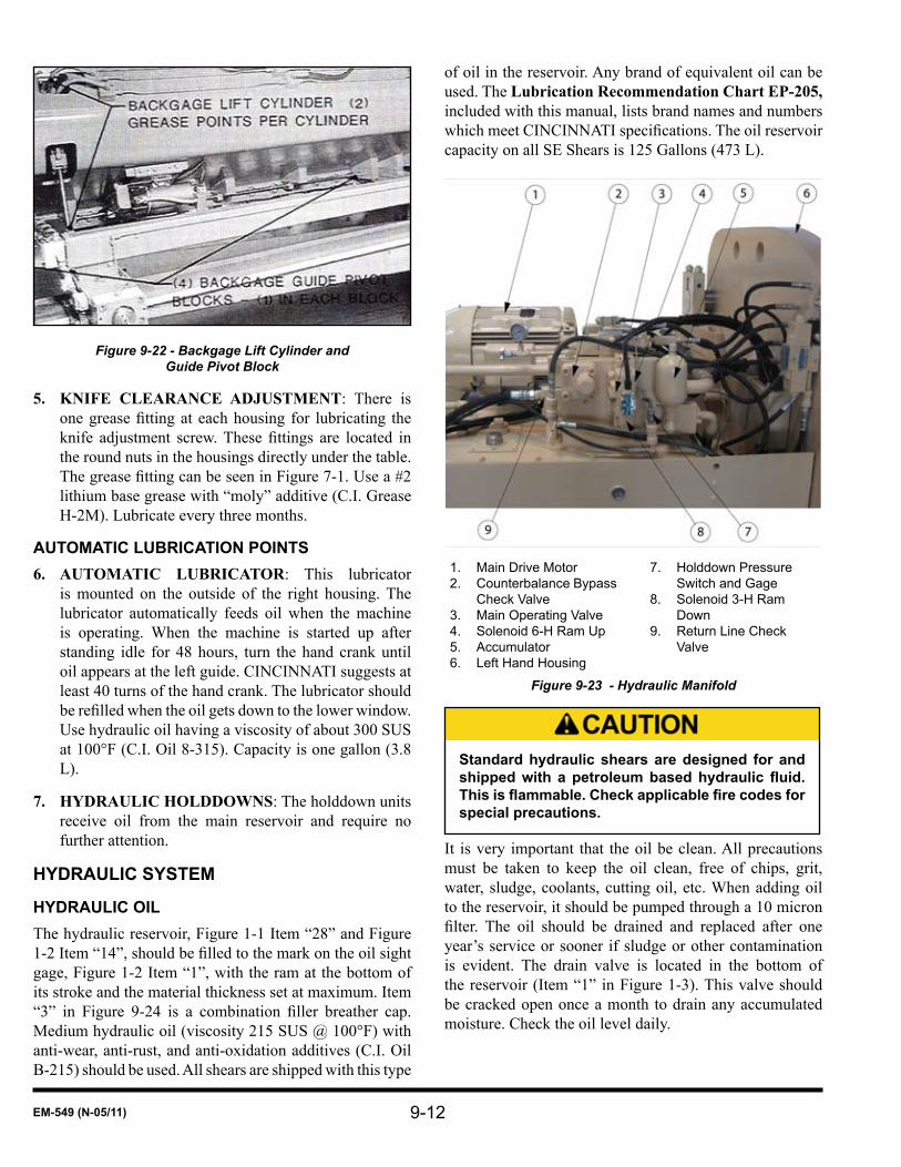
9-12EM-549 (N-05/11)
Figure 9-22 - Backgage Lift Cylinder and Guide Pivot Block
KNIFE CLEARANCE ADJUSTMENT5. : There is onegreasefittingateachhousing for lubricating theknife adjustment screw.Thesefittings are located inthe round nuts in the housings directly under the table. ThegreasefittingcanbeseeninFigure7-1.Usea#2lithium base grease with “moly” additive (C.I. Grease H-2M). Lubricate every three months.
AUTOMATIC lUBRICATION POINTSAUTOMATIC LUBRICATOR6. : This lubricator is mounted on the outside of the right housing. The lubricator automatically feeds oil when the machine is operating. When the machine is started up after standing idle for 48 hours, turn the hand crank until oil appears at the left guide. CINCINNATI suggests at least 40 turns of the hand crank. The lubricator should berefilledwhentheoilgetsdowntothelowerwindow.Use hydraulic oil having a viscosity of about 300 SUS at 100°F (C.I. Oil 8-315). Capacity is one gallon (3.8 L).
HYDRAULIC HOLDDOWNS7. : The holddown units receive oil from the main reservoir and require no further attention.
HYDRAUlIC SYSTEM
HYDRAUlIC OIlThe hydraulic reservoir, Figure 1-1 Item “28” and Figure 1-2Item“14”,shouldbefilledtothemarkontheoilsightgage, Figure 1-2 Item “1”, with the ram at the bottom of its stroke and the material thickness set at maximum. Item “3” in Figure 9-24 is a combination filler breather cap.Medium hydraulic oil (viscosity 215 SUS @ 100°F) with anti-wear, anti-rust, and anti-oxidation additives (C.I. Oil B-215) should be used. All shears are shipped with this type
of oil in the reservoir. Any brand of equivalent oil can be used. The Lubrication Recommendation Chart EP-205, included with this manual, lists brand names and numbers whichmeetCINCINNATIspecifications.Theoilreservoircapacity on all SE Shears is 125 Gallons (473 L).
Main Drive Motor1. Counterbalance Bypass 2. Check ValveMain Operating Valve3. Solenoid 6-H Ram Up4. Accumulator5. Left Hand Housing6.
Holddown Pressure 7. Switch and GageSolenoid 3-H Ram 8. DownReturn Line Check 9. Valve
Figure 9-23 - Hydraulic Manifold
Standard hydraulic shears are designed for and shipped with a petroleum based hydraulic fluid. This is flammable. Check applicable fire codes for special precautions.
It is very important that the oil be clean. All precautions must be taken to keep the oil clean, free of chips, grit, water, sludge, coolants, cutting oil, etc. When adding oil to the reservoir, it should be pumped through a 10 micron filter. The oil should be drained and replaced after oneyear’s service or sooner if sludge or other contamination is evident. The drain valve is located in the bottom of the reservoir (Item “1” in Figure 1-3). This valve should be cracked open once a month to drain any accumulated moisture. Check the oil level daily.

9-13 EM-549 (N-05/11)
Temperature/Level 1. SwitchMagnetic Trap2. Oil Filler - Breather3.
Hydraulic Reservoir4. Manifold Assembly5.
Figure 9-24 - Hydraulic Reservoir Assembly
AIR BREATHERFigure9-24Item“3” isacombinationfiller-breather.Asthe oil is pumped out of the reservoir to the cylinders duringoperation,theoilisreplacedbyair.Thefillercapincorporatesa40micronelementwhichfilters theairasit enters the reservoir. This element may require periodic cleaning.
MAGNETIC TRAPA magnetic trap (Figure 9-24 Item “2”) is provided in the oil reservoir cover. The magnets are attached to the plug and should be removed from the reservoir and cleaned once a year.
OIl fIlTERSThere are two filters provided on each shear; a suctionfilteranda return linefilter.Thesuctionfilter is a sumptypestrainerwitha100meshfilterelement.Thisfilterislocated in the reservoir on the end of the intake pipe to thepump.Toinspectorreplacefilterelement,removethescrews from suction cover Figure 9-25 Item “2” and from the pump inlet flange Item “1”. The pump suction pipewiththesuctionfilterattachedmaythenbeliftedoutofthereservoirforreplacement.Itisrecommendedthatthisfilterbe replaced rather than cleaned, unless it can be cleaned bybackflushing(frominsideout).Thefiltercanthenbeunscrewedfromtheintakepipe.Thenewfiltershouldbeinstalled hand-tight. Reinstall the cover and screws. The returnlinefilter,Item“2”onFigure9-26,ismountedonthe right end of the reservoir. It has a nominal rating of 10
micronwith50GPM(l89Lperminute)maximumflowrate. The filter cartridge should be replaced after 1000operatinghours.Oil is forced through thefilterandheatexchanger by back pressure in the return line generated by a return line cartridge type check valve.
Pump Coupling (Under 1. Guard)Main Drive Motor2.
Pump Inlet Flange3. Suction Cover4.
Figure 9-25 - Pump Assembly
Return Line from 1. Air Cooled Heat Exchanger
Return Line Filter2. Main Drive Motor3. Reservoir4.
Figure 9-26 - Hydraulic Reservoir Assembly
AIR-TYPE HEAT EXCHANGERThe 6SE Series and larger machines are equipped with an air-type heat exchanger. The heat exchanger is equipped with a thermostatically controlled electric fan. The thermostat should be set to start the fan at 120°F (48.9°C).

9-14EM-549 (N-05/11)
CHECKING AND SETTING PRESSURES
IMPORTANT: Before checking and setting pressures, operate the shear through full length strokes to bring the hydraulic oil up to an operating temperature of 120°F (48.9°C) or above.
MAIN RElIEf PRESSUREA pressure test station is provided in the left end of the manifold for checking main relief pressure. See Figure 9-27. The correct pressure setting is shown on a tag on the top of the tank cover. The test station is furnished with a special pipe nipple, valve, and a pressure gage. The adjustment for main relief pressure is the knob on the right side of the tri-pressure relief valve, Figure 9-27 Item “8”. When solenoid 5H is energized, the main relief pressure is available to the system. For machines equipped with Power Front Feed Rolls (Optional) or Cushion Clamp (Special), when solenoid 5H is manually overridden then solenoid 11H must also be overridden at the same time. The 11H solenoid is located on top of the sub plate mounting for the tri-pressure relief valve.
Solenoid 10-H Decrease 1. RakeRake Control Valve2. Solenoid 9-H Increase 3. RakeMain Relief Pressure 4. Gage (Tag on Tank Cover)Solenoid 8-H Holddown 5. PressureHolddown Pressure 6.
AdjustmentPower Feed Rolls (Aux) 7. Pressure AdjustmentTri-Pressure Relief Valve8. Ram Down (Main Relief) 9. Pressure AdjustmentSolenoid 5-H Main 10. Operating PressureCounterbalance Valve11. Counterbalance 12. Adjustment
Figure 9-27 - Main Relief Pressure Adjustment
To set the pressure, turn the MODE selector to “OFF”
and remove the key. Start the main drive motor. With the valve to gage closed, manually override solenoid 5H by depressing pin in the end of the solenoid cover. With the pin depressed, open the valve, read the pressure, close the valve, and release the solenoid pin. It is important to follow this sequence to protect the gage from damage due to sudden application or release of pressure. If the pressure is not the same as shown on the tag, reset it by loosening the locknut under the adjusting screw on the tri-pressure relief valve Figure 9-27 Item “8”. Turn the adjusting screw clockwise to increase pressure or counterclockwise to decrease pressure. Turn about 1/8 turn at a time. Tighten locknut after adjustment and recheck pressure as described above. Repeat procedure until proper setting is attained.
COUNTERBAlANCE PRESSUREIMPORTANT: Counterbalance pressure should only be
checked or set with oil temperature at 120°F (48.9°C) or higher.
A test station in Figure 9-28 is provided on the top face of the manifold for checking counterbalance pressure. The test station is furnished with a special pipe nipple, valve, and pressure gage. The correct pressure is shown on a tag Figure 9-28 and Figure 9-29 Item “2” next to the test station. The adjustment for this pressure is the knob on the counterbalance valve Item “1”. The valve is located on the front of manifold at the upper right corner.
To read the pressure it is necessary to stroke the ram. With the motor running, the MODE selector on “SINGLE STROKE”, MATERIAL LENGTH selector on maximum and the MATERIAL THICKNESS selector set for maximum material thickness, run the ram through full length strokes. Have an assistant read the pressure gage by opening the valve after the ram has started down and closing it before the ram reverses at the bottom. This shutoff valve is provided to protect the gage from surges in pressure. The gage reads counterbalance pressure.
If the pressure is not the same as shown on the tag, reset it by loosening the locknut under the adjusting screw. Turn the knob clockwise to increase pressure or counterclockwise to decrease it. Tighten the locknut and recheck pressure as outlined above. Repeat this procedure until proper setting is attained.

9-15 EM-549 (N-05/11)
Counterbalance Valve1. Counterbalance Pressure Tag2. Counterbalance Pressure Adjust3. Counterbalance Pressure Gage4.
Figure 9-28 - Counterbalance
HOlDDOWN PRESSUREA gage and valve for checking holddown pressure are permanently mounted on the rear of the hydraulic manifold at the lower corner nearest the left housing. See Figure 9-29. The correct holddown pressure is shown on a tag below the gage. The adjustment for this pressure is the knob on the left end of the tri-pressure relief valve Item “8” in Figure 9-27. When solenoid 8H is energized the holddown relief pressure is available to the system. For machines equipped with Power Front Feed Rolls (Optional) or Cushion Clamp (Special), when solenoid 8H is manually overridden then solenoid 11H must also be overridden at the same time. The 11H solenoid is located on top of the sub plate mounting for the tri-pressure relief valve Figure 9-27 Item “8”.
HOlDDOWN PRESSURE SWITCHThe holddown pressure switch is located in a tee connection between the manifold and holddown pressure gage. Figure 9-29 Item “6”. The holddown pressure switch is set using pushbuttons on the switch. Follow the switch manufacturer’s instructions to adjust the switch. Set the pressures per Figure 9-29 Item “5” - Holddown Pressure Tag. Adjustment is only necessary when the switch is replaced.
Counterbalance Bypass Check Valve1. Solenoid 6-H Ram Up2. Main Operating Valve3. Solenoid 3-H Ram Down4. Holddown Pressure Tag5. Holddown Pressure Switch and Gage6. Accumulator7.
Figure 9-29 - Holddown Pressure Adjustment
Do not shear material if the holddown pressure is not set to the pressure shown on the tag or it drops excessively during the down stroke causing a machine fault. Insufficient pressure could allow material to tip up during a shear cut, resulting in possible injury to the operator. Excessive pressure could damage the shear.
AUXIlIARY RElIEf PRESSURE For machines equipped with Power Front Feed Rolls (Optional) or Cushion Clamp (Special) there is a third adjustment on the tri-pressure relief valve Item “8” in Figure 9-27. The adjustment for this pressure is Figure 9-27 Item “7”. The correct pressure for Power Front Feed Rolls is 1000 PSI (6895 kPa). For Cushion Clamp the pressure is set to obtain holddown pressure as quickly as possible without marking the material being sheared. This is usually between 100 and 400 PSI (690 and 2758 kPa).
To set the pressure, turn the MODE selector to “OFF” and remove the key. Start the main drive motor. With the valve to the Main Relief Pressure gage, Figure 9-27 Item “4”, open, manually override solenoid 11H by depressing the pin in the end of the solenoid cover, and read the pressure gage. Then release the pin. If the pressure is not correct,

9-16EM-549 (N-05/11)
reset by loosening the locknut under the adjusting screw on the tri-pressure relief valve. Turn the adjusting screw clockwise to increase pressure or counterclockwise to decrease pressure. Turn the screw about 1/8 turn at a time. Tighten the locknut after each adjustment and recheck pressure as described above. Repeat procedure until proper setting is obtained.
ACCUMUlATOR
The accumulator, Item “7” on Figure 9-29, is in the holddowncircuitandislocatedontheholddownlineflangeon the left end of the hydraulic manifold. Its purpose is to maintain holddown pressure during the cutting stroke by replacing any oil that may leak past the valve spool. This accumulator has a pre-charge as of approximately 2050 PSI (6895 kPa) in its gas bag. The gas must be dry nitrogen. The pressure should be checked yearly. Its effectiveness can be checked by observing the holddown pressure gage during
a full stroke. If the accumulator is operating properly, it will maintain the set holddown pressure throughout the full stroke. A slight drop of less than 200 PSI (1379 kPa) is normal, but a larger drop is excessive. This should be checked during a full length stroke.
lIGHT BEAM SHEARING GAGE
The light beam shearing gage consists of a row of 110V incandescent spot lamps. The lamps are mounted on a channellocatedinafixedpositionabovetheram.Nofront-to-back adjustment is provided for the gage channels. On the 4SE Series, a shield is mounted on top of the holddown beam to adjust the shadow line. To achieve the sharpest shadow line on material at the cutting edge of the lower knife, loosen the button head screws holding the shield and adjust the shield. Retighten the screws. The light beam shearing gage should be checked and adjusted if necessary whenever knives are changed.

9-17 EM-549 (N-05/11)
TROUBlESHOOTINGEffective and safe troubleshooting procedures are acquired through experience and a thorough knowledge of the machine and its operation, The use of maintenance instructions, assembly drawings, and schematics provided with the machine will be helpful in resolving problems with the machine.
The following chart was developed to aid in troubleshooting problems with the machine. The chart contains questions frequently asked by our customers.
Ifmajorrepairisrequiredoriftheproblemhasnotbeenidentifiedbyusingthechart,contacttheServiceDepartmentatClNCINNATI lNCORPORATED for assistance.
PROBlEM POSSIBlE CAUSE REPAIR
Drive motor stalls
Main relief valve set too high. Reset relief valve.
Electrical leads to shear are too small Check if wire size is sufficient for amperage shown on main electrical enclosure - Replace if necessary.
Insufficient supply voltage at shear. Check factory supply. Correct factory wiring or contact local electric utility. See Section 2.
Ram will not move
Faulty footswitch. Repair or replace as necessary.
Ram tries to go up, but cannot because a piston is against its upper head.
Check adjustment of low side potentiometer. Check electronic control configuration.
Ram tries to go down, but cannot because a piston is against its lower head.
Check adjustment of high side potentiometer. Check electronic control configuration.
Tri-pressure relief valve does not energize to provide pilot pressure. Check tri-pressure relief valve and repair or replace as necessary.
Electrical malfunction. Check electrical circuits for main operating valve and tri-pressure relief valve.
Main operating valve malfunctioning. Check valve operation and repair or replace as necessary.
Ram stalls during cut
Rake set too low. Reset MATERIAL THICKNESS control to match material thickness or increase to higher rake.
Main relief pressure set too low. Reset relief valve.
Improper knife clearance. Reset clearance.
Attempting to shear material beyond shear capacity. See Specifications chart and Shear Capacities Bulletin PT-30491.
Malfunctioning tri-pressure relief valve. Repair or replace valve.
Electrical malfunction in tri-pressure relief circuit. Check solenoid “5H” and corresponding electrical circuit.
Rake cannot be increased
MATERIAL THICKNESS control potentiometer is not functioning. Check control potentiometer operation and replace if necessary.
Rake control valve not functioning. Check valve and repair or replace if necessary. Block left end of ram with screw jack before removing valve.
Tri-pressure relief valve fails to shift to provide pressure.
Check operation of valve and electrical circuit and repair or replace as necessary.
Rake cannot be decreased
MATERIAL THICKNESS control potentiometer is not functioning. Check control potentiometer operation and replace if necessary.
Rake control valve not functioning. Check valve and repair or replace If necessary. Block left end of ram with screw jack before removing valve.
Ram falls evenly (both sides) when sitting idle
Insufficient counterbalance pressure. Check counterbalance pressure and reset if necessary.
Faulty counterbalance valve. Repair or replace - Block right end of ram with screw jack before removing valve.
Faulty counterbalance check valve. Repair or replace - Block right end of ram with screw jack before removing valve.
Ram falls unevenly when sitting idle
Faulty piston rod seals allow fluid to leak past pistons. Replace both rod packings, even if only one is bad.
Faulty rake control valve allowing fluid to leak past valve.
Check valve and repair or replace if necessary - Block left end of ram with screw jack before removing valve.

9-18EM-549 (N-05/11)
PROBlEM POSSIBlE CAUSE REPAIR
Holddowns do not hold or material raises from table during cut
Insufficient holddown pressure. Check and reset pressure.
Pressure switch set too low. Readjust pressure switch.
Pressure falls immediately due to ruptured accumulator bladder or no pre-charge. Replace bladder and/or recharge accumulator.
Pressure falls rapidly due to improper accumulator pre-charge. Check pre-charge.
Holddown valve not operating properly. Check operation of valve and electrical circuit.Repair or replace as necessary.
Dull knives. Rotate or change knives.
Improper knife clearance. Reset knife clearance.
Tri-pressure relief valve failing to shift to provide pressure.
Check operation of valve and electrical circuit.Repair or replace as necessary.
Hydraulic fluid excessively hot (Shears with heat exchanger)
Dirty return line filter. Replace filter element.
Ram reverses at top of stroke With severe “thump”
Fixed UP limit is set incorrectly, allowing piston to strike top of cylinder. Check configuration settings.
Ram reverses at bottom of stroke with severe “thump”
Fixed DOWN limit is set incorrectly, allowing piston to strike bottom of cylinder. Check configuration settings.
Ram does not maintain rake during operation
Faulty piston rod seals allow fluid to leak past pistons. Replace both rod packings, even if only one Is bad.
Faulty rake control valve. Check valve and repair or replace if necessary - Block left end of ram with screw jack before removing valve.

9-19 EM-549 (N-05/11)
MAINTENANCE CHECKlIST - SE SERIES HYDRAUlIC SHEARS
CHECK OR ADJUSTMENT
DA
IlY
WEE
KlY
MO
NTH
lY
3 M
ON
THS
6 M
ON
THS
YEA
RlY
1. Check holddowns for proper operation - Correct if necessary. X
2. Inspect knives for nicks or wear - Turn, replace, or sharpen if necessary.
X
3. Check to see that all guards and barriers are in place and in good condition.
X
4. Wipe machine with clean rags, especially the clevis pin. X
5. Check MATERIAL LENGTH and MATERIAL THICKNESS controls -adjust if necessary.
X
6. Check knife bolts and ram adjusting nuts - Tighten if necessary. X
7. Check knife and ram guide clearance - Adjust if necessary. X
8. Check entire machine for loose fasteners, especially backgage and holddown beam bolts - Tighten if necessary.
X
9. Check machine level - Re-level if necessary. X
10. Check accumulator pre-charge pressure and recharge if necessary. X
lUBRICATION SCHEDUlE
1. Check automatic lubricator oil level and add oil if necessary - Turn hand crank 40 turns. X
2. Check hydraulic reservoir oil level - Add oil if necessary. X3. Check for water in hydraulic reservoir. X4. Lubricate motor and pump coupling. X5. Grease backgage pivot blocks, lift cylinder clevises, and knife
clearance screw. X
6. Check oil temperature in reservoir - Adjust temperature control if necessary. X
7. Replace return line filter cartridge. X8. Remove magnetic trap, clean, and replace. X9. Replace the intake suction filter (or clean). X
10. Drain, clean, and refill hydraulic reservoir. Use a 10 micron filter when filling. Replace return line filter in Step 7 at this time. X
11. Check hydraulic pressures - Adjust if necessary. X
A PERIODIC MAINTENANCE INSPECTION SHOULD BE MADE ON THIS MACHINE AS INDICATED ABOVE. INTERVALS ARE BASED ON ONE SHIFT OPERATION. DETAILED INSTRUCTIONS FOR SERVICING THE MACHINE CAN BE FOUND IN SECTION 9 OF THIS MANUAL.

9-20EM-549 (N-05/11)

10-1 EM-549 (N-05/11)
SEcTiON 10 SErVicE aNd parTS
ORDERING REPAIR PARTSWhen ordering repair parts, be sure to furnish the following information:
The serial number of the CINCINNATI Shear. This 1. is located on the machine’s capacity plate and on the right end of the upper knife seat.
The part number and part name, which can be 2. obtained from the assembly drawing provided with the machine.
As complete a description of the part as possible.3.
Delivery required.4.
It is sometimes necessary to furnish subassemblies 5. instead of single parts. In such cases, CINCINNATI reserves the right to ship and to invoice accordingly.
RETURNING PARTS fOR CREDITNo item is to be returned without prior authorization. 1. Please write or call the factory (513-367-7100) for instructions and the returned goods authorization number.
The returned goods authorization number must be 2. shown on the outside of the package being returned. Unauthorized shipments will be returned to the sender freight collect.
SERVICECINCINNATI INCORPORATED Service includes:
Established field service having numerous local1. officesforpromptserviceassistance.Factorytrainedservicemen are available to assist with any service problem. This includes service ranging from minor repairs and adjustments to major reconditioning jobs.
Planned Maintenance Service. This is a program 2. designed to give comprehensive inspections and recommendations concerning the condition of the equipment. Planned Maintenance Service is specifically tailored to timely inspections, qualifiedrecommendations, and expert field assistance withrepairs to the equipment.
Total Knife Service. This is a program designed 3. to eliminate the problems involved in turning and adjusting shear knives. Also, the program includes simple adjustment checks that will provide some indications of the status of the equipment.

10-2EM-549 (N-05/11)


CINCINNATI is a registered trademark of Cincinnati Incorporated.
CINCINNATIRC O P Y R I G H T 2 0 11
C I N C I N N AT I I N C O R P O R AT E D