operation and service instructions - bredal a/s overlap is 20 cm. remember: if the pto shaft is...
TRANSCRIPT

Operation and Service Instructions
Bredal A/S
Type F2 English
No. 02008006
Vers. 1. 2010 Side 2 af 63
1 Spreader Info
EU Declaration of Compliance (Directive 89/392/EEA, Annex II, supl. A) Manufacturer: BREDAL A/S Overgårdsvej 19, DK 7120 Vejle Ø Hereby states that BREDAL Type Serial number Only for Teejet500 control Cal. figure _____________________________
App. Rate cm3/pulse______________________
Pulses/100 metres _______________________
Computer no._____________________________
Is manufactured in compliance with the machinery directive (Directive 89/392/EEA) with the latest amendment, and with national provisions Bredal DK-7120 Vejle Ø 10th Januar 2010

Vers. 1. 2010 Side 3 af 63
Contents
1 Spreader Info .............................................................................................................................. 2
2 Introduction ................................................................................................................................ 5
3 Road safety.................................................................................................................................. 6
4 Technical data. ........................................................................................................................... 6
5 Safety ........................................................................................................................................... 6
6 Mounting on tractor. ................................................................................................................. 7
6.1 Adjusting the land wheel. ............................................................................................................ 8
6.2 Adjusting the PTO shaft. ............................................................................................................. 8
7 Setting of application rate ........................................................................................................... 9
7.1 Principle of the application system. ............................................................................................. 9
7.2 Introduction to the Bulk density kit. ........................................................................................... 10
7.3 Dose charts. .............................................................................................................................. 11
7.4 Introduction to the slide ruler. .................................................................................................... 14
7.5 Max. Capacity per minute ......................................................................................................... 15
8 Adjustments for spreading ...................................................................................................... 16
8.1 12 – 36 meter working width ..................................................................................................... 16
8.2 Headland spreading on 12-28 meter ......................................................................................... 17
8.3 Headland spreading on 28-36 meter ......................................................................................... 19
9 Trouble shooting ...................................................................................................................... 20
9.1 Incorrect balanced spreading. ................................................................................................... 21
9.2 Incorrect application rate ........................................................................................................... 21
10 Maintenance. ............................................................................................................................ 23
10.1 Replacing the V belts. ............................................................................................................... 24
11 Fertiliser quality ....................................................................................................................... 25
12 Performing a spread test and adjustment of spreading. ...................................................... 26
12.1 Correction of the spread pattern ............................................................................................... 27
12.2 Performing a spread test with headland spreading. .................................................................. 29
13 Spreading on narrow Widths .................................................................................................. 30
13.1 Spreading in hilly terrain ............................................................................................................ 30
14 Driving to and from tramlines ................................................................................................ 31
14.1 Start and stop by 150 ................................................................................................................. 32
14.2 Start and stop by 300 ................................................................................................................. 32
14.3 Start and stop by 600 ................................................................................................................. 33
15 Performing a static calibration test ........................................................................................ 33
16 Special fertilisers ...................................................................................................................... 34
Vers. 1. 2010 Side 4 af 63
16.1 N34 Prilled Ammonium Nitrate .................................................................................................. 34
16.2 Pure potash ............................................................................................................................... 34
16.3 Sulphate of Ammonia ................................................................................................................ 35
16.4 Prilled Urea ................................................................................................................................ 35
16.5 Granulated Urea ........................................................................................................................ 36
17 Spreading of Slug Pellets, Rape and Mustard ....................................................................... 37
18 Spreading of slug pellets (only for F2 and F2W with hydraulic rating) ............................. 38
19 Late application ........................................................................................................................ 39
20 F2W with hydr rating and load cell ....................................................................................... 40
20.1 Symbol selection ....................................................................................................................... 42
21 Start up ..................................................................................................................................... 43
21.1 Speed sensor ............................................................................................................................ 43
21.2 Power supply for the computer ................................................................................................. 43
21.3 Monting the computer ................................................................................................................ 43
21.4 Encoding forward speed ........................................................................................................... 43
21.5 Calibration of hydraulic system ................................................................................................. 43
22 Operation .................................................................................................................................. 45
22.1 Operation screen ....................................................................................................................... 45
22.2 Operation function 2 .................................................................................................................. 46
22.3 Hydraulic change of headland gear (Optional equipment) ........................................................ 47
22.4 Calibration of the application rate .............................................................................................. 48
22.5 Calibration without load cells ..................................................................................................... 49
22.6 Main menu ................................................................................................................................. 50
23 Operation alarms ..................................................................................................................... 61
24 System plans ............................................................................................................................. 62

Vers. 1. 2010 Side 5 af 63
2 Introduction BREDAL type F2 & F2W spreaders are solely constructed for spreading dry granular materials with little or no dust content onto agricultural fields. It is the responsibility of the operator that the machine he is operating only spreads materials which do not harm his own or others health and property. The machines must only be operated and maintained by persons who are informed about and fully understand the dangerous parts of the machine. On the Serial Number plate is indicated machine type (F2 or F2W), the serial number and the production year. In addition is shown the maximum gross and the net weight. The difference is the allowed payload. This instruction handbook contains settings for your guidance concerning the spreading of most common types of prilled or granular fertilisers found on the market. However, fertiliser quality is not a constant. It may vary from year to year and even from one batch to the next. Due to this BREDAL A/S cannot not take any responsibility for the quality of spreading. This applies to the type fertiliser and to the correct fitting of spare parts onto the machine.
It is solely the responsibility of the operator, to ensure that the machine performs in a way, that achieves acceptable results. BREDAL A/S is constantly testing the fertiliser types, which are found on the market. If any doubt about the spread ability of a particular fertiliser should occur, a simple way of carrying out a field test is described in part 12 in this handbook. You are also always welcome to call the importer of the BREDAL products in your country or to contact the BREDAL factory direct. Points to consider. Your fertiliser spreader will each year broadcast several times its own value in fertiliser. The ef-fect of a poor application, due to the lack of maintenance and control, poor fertiliser quality or operation errors, can create yield losses which may many times exceed your investment in the machine. Please give this some thought next time you are buying fertiliser, carrying out a spread test or completing maintenance work. The machine is manufactured by:
Bredal A/S Overgårdsvej 19 DK-7120 Vejle Ø Tlf.: 75 89 51 77 Fax.: 75 89 59 72
Internet: www.bredal.com E-mail.: [email protected]

Vers. 1. 2010 Side 6 af 63
3 Road safety
It is important that road safety is considered. Check the following points: • The traffic lights are undamaged, fully operational and are connected to the the plug of
the tratorwhen ever driving on public roads. Remember to clean the lights every time you have been spreading fertiliser.
• Bolts on the lower link arms, drawbar and wheels should regularly be checked and re-tightened.This must be done before you put the machine into operation for the first time.
• When connecting the machine onto the tractor, check that the pins are the correct size or category and that they are proper locked.
4 Technical data. Type Capacity
(liter) Net weight
(kg) Loading height (cm)
Width x length (cm)
Working width
F 2 standard 1500 700 136 240 x 130 12 – 36 m F 2 2500 2400 740 165 240 x 130 12 – 36 m F 2 3000 3000 750 175 240 x 130 12 – 36 m F 2 3200 3200 790 165 300 x 130 12 – 36 m.
5 Safety Never stand close to the discs when they are rotating. For example,the tractor pto must be disengaged if persons or animals are within a radius of 30 metres from the spread discs of the machine, when operating with 1000 rpm on the tractor Pto and a radius of 20 metres operating with 540 rpm on the pto. Guards on the pto shafts must be undamaged and correctly mounted. Never stand on the guard over the discs or on the protection guard, while the discs are running. Standing on the machine during work and road transport is strictly forbidden. Avoid loading of hard heavy items, such as metal parts or stones in the hopper. They can cause damage to the machine and be dangerous for anything nearby.
- During service work on type F2 and F2W, the tractor lower link arms must be lowered to lowest position and the machine must be supported by the parking legs.
- During work with type F2 and F2W, the top link must in the correct work position for the machine, that is in-between parallel to the lower link arms and horizontal. If the angle of the top linkage is to steep, it greatly increases the risk of damaging the chassis frame of the machine.
- Connecting type F2 and F2W onto the tractor: Never work in-between tractor and spreader, when anyone is in the cab of the tractor. Make sure that the tractor handbrake is securely tightened and that it is fully functional.

Vers. 1. 2010 Side 7 af 63
6 Mounting on tractor.
The distance from the ground to the discs must not be less than 75 cm. Optimum is aprox. 85 cm, but there is no upper limit for this distance Check chains must be tightened completely when the spreader is in working position. If this is not adjusted, the pressure between the landwheel and the tractor wheel will cause the spreader to move sidewards, which may affect accuracy in spreading. The landwheel must always run on the centre of the tractor wheel touching both rows of lugs on the tractor tyre.
• Type F2 : The three point linkage points meets the measurements for the ISO standard for Cat.2 tractors.
• Type F2W : The three point linkage points meets the measurements for the ISO stan-dard for Cat. 3 tractors.
Make sure that the lower link arms and the top linkage are as close to parallel with each other as possible. A steep angled top linkage may overload the tractor and machine attachment points. The spreader must be mounted parallel to the surface or incline slightly towards the tractor. The spreader must not incline backwards, not even when fully loaded. It must be posi-tioned straight behind the tractor, i.e. perpendicular to the driving direction with equal parts of the machine to the left and right side of the centreline of the tractor.
85 - 90 cm

Vers. 1. 2010 Side 8 af 63
6.1 Adjusting the land wheel. Drive to the the feed mechanism is engaged/disengaged hydraulically by connecting the hose from the land wheel to a single acting spool valve. Always remember to close the Ball Valve on the hose, to lock the landwheel when driving on the road. The spool valves on modern trac-tors rarely have no leakage and may not withstand the pressure of the spring system on the landwheel over a distance. Forgetting to close the ball valve, may risk metering fertiliser onto the road, losing expensive materials and having a negative impact on the environment. On some of the F2 and F2W versions der might be a pilotcontrolled valve instead of the ball valve, this valve automatically closes every time it´s operated. The landwheel drive feed mechanism driving the feeding belts, has the advantage that the for-ward speed can be freely selected , without affecting the application rate. Due to the fact that the landwheel is driving on the surface of the tractor or spreader rear wheel, one metre driven forward in the field will be transferred to the surface of the landwheel, which then also will turn one metre. Therefore you are free to change the size of the tractor or spreader wheel, without affecting the accuracy of the metering system e.g. changing from flotation to row crop wheels.
ca.3-5 cm.
6.2 Adjusting the PTO shaft.
Check the length ot the Pto shaft and shorten if necessary to ensure it cannot be “bottomed” under any circumstances – particularly when the spreader is in the raised position. The mini-mum overlap is 20 cm. Remember: If the pto shaft is shortened the ends must be filed to debur to avoid the two halves sticking together or wearing prematurely. Regularly grease the inner tube and univer-sal joints

Vers. 1. 2010 Side 9 af 63
7 Setting of application rate
To achieve the correct application rate the following measurements should be checked:
1. At Scale 8 on the rear door handle, there should be a distance of 40 mm measured verti-cally between the floorbelt and the bottom edge of each regulating slide shown as B below. Always move the scale adjustment handle down to the setting required. Adjust using the lock nuts on the threaded rod above each regulating slide.
The distance between the side rubbers should be between 112mm and 115mm directly below the rear doors shown as C below
7.1 Principle of the application system. The Bredal F2 / F2W machines are built with an active metering system consisting of two floor-belts with adjustable reardoors providing two precise openings where the material metered out of the hopper. Fertiliser is positively fed from the hopper and for a particular setting of the regulating slides the same volume is metered from the hopper whether the material is prilled, granular, blended or straights. A simple calculation from the application rate in kg/ha and the bulk density of the fertil-iser means that by referring to a single chart for the spread width required is the only information needed to set the spreader. The flow is controlled by the landwheel. The faster you travel, the faster the floorbelts turn which provides the correct amount spread per hectare, no matter what forward choosen.

Vers. 1. 2010 Side 10 af 63
7.2 Introduction to the Bulk density kit. To set the application rate it is necessary to know the Bulk Density of the material to be spread. A Bulk Density kit can be supplied with the spreader to give a direct reading. Fill up the plastic container with the material to be loaded into the spreader. Gently tap the con-tainer on the floor and refill so that the material is level with the container top edge. Hang the con-tainer in the “W” cut into the shorter end of the arm (use the x1 cutout). Adjust the counterbalance until the balance arm is horizontal. Note the Bulk Density by reading directly off the scale on the balance arm, taking a reading in line with the head of the fine adjustment bolt. To “Zero” the Bulk Density Kit, fill the container with water and hang on the x1 cutout on the bal-ance arm. Slide the balance weight until the arm is balanced in the horizontal position. The head of the adjuster bolt on the counterweight should read 1.0 kg/lt. To correct, release the locknut on the adjustment bolt, reset the position and retighten.
Fig. 4. Bulk density kit for determination of specific bulk density.

Vers. 1. 2010 Side 11 af 63
7.3 Dose charts. 12 m 15 m Scale Axle ½ Axle 1 Axle 2 Axle 3 Scale Axle ½ Axle 1 Axle 2 Axle 3
-2 48 93 174 301 -2 38 74 139 241 -1 57 111 209 367 -1 46 89 167 294 0 66 129 244 433 0 53 103 195 346 1 75 147 279 499 1 60 118 223 399 2 84 165 314 565 2 67 132 251 452 3 94 183 349 631 3 75 146 279 505 4 103 201 384 698 4 82 161 307 558 5 112 219 419 764 5 90 175 335 611 6 121 237 454 830 6 97 190 363 664 7 130 254 489 896 7 104 203 391 717 8 139 272 523 962 8 111 218 418 770 9 148 290 558 1028 9 118 232 446 822 10 157 308 593 1094 10 126 246 474 875 11 166 326 628 1160 11 133 261 502 928 12 175 344 663 1227 12 140 275 530 982 13 184 362 698 1293 13 147 290 558 1034 14 193 380 733 1359 14 154 304 586 1087 15 202 398 768 1425 15 162 318 618 1140 16 211 416 803 1491 16 169 333 642 1193
Axle ½ is optional equipment. 16 m 18 m Scale Axle ½ Axle 1 Axle 2 Axle 3 Scale Axle ½ Axle 1 Axle 2 Axle 3
-2 36 70 131 226 -2 32 62 116 201 -1 43 83 157 275 -1 38 74 139 245 0 50 97 183 325 0 44 86 163 289 1 56 110 209 374 1 50 98 186 333 2 63 124 236 424 2 56 110 209 376 3 71 137 262 473 3 63 123 233 421 4 77 151 288 524 4 69 134 256 465 5 84 164 314 573 5 75 146 279 509 6 91 178 341 623 6 81 158 303 553 7 98 191 367 672 7 87 169 326 597 8 104 204 392 722 8 93 181 349 641 9 111 218 419 771 9 99 193 372 685 10 118 231 445 821 10 105 205 395 729 11 125 245 471 870 11 112 217 419 773 12 131 258 497 920 12 117 229 442 818 13 138 272 524 970 13 123 241 465 862 14 145 285 550 1019 14 129 253 489 839 15 152 299 576 1069 15 135 265 512 950 16 158 312 602 1118 16 141 277 535 994

Vers. 1. 2010 Side 12 af 63
20 m 24 m Scale Axle ½ Axle 1 Axle 2 Axle 3 Scale Axle ½ Axle 1 Axle 2 Axle 3
-2 29 56 104 181 -2 24 47 87 151 -1 34 67 125 220 -1 29 56 105 184 0 40 77 146 260 0 33 65 122 217 1 45 88 167 299 1 38 74 140 250 2 50 99 188 339 2 42 83 157 283 3 56 110 209 379 3 47 92 175 316 4 62 121 230 419 4 52 101 192 349 5 67 131 251 458 5 56 110 210 382 6 73 142 272 498 6 61 119 227 415 7 78 152 293 538 7 65 127 245 448 8 84 163 314 577 8 70 136 262 481 9 89 174 335 617 9 74 145 279 514 10 94 185 356 656 10 79 154 297 547 11 100 196 377 696 11 83 163 314 580 12 105 206 398 736 12 88 172 322 614 13 110 217 419 776 13 92 181 349 647 14 116 228 440 815 14 97 190 366 680 15 121 239 461 855 15 101 100 384 713 16 127 250 482 895 16 106 208 402 746
Axle ½ is optional equipment
28 m 30 m Scale Axle ½ Axle 1 Axle 2 Axle 3 Scale Axle ½ Axle 1 Axle 2 Axle 3
-2 21 40 75 129 -2 19 37 70 120 -1 24 48 90 157 -1 23 44 84 147 0 28 55 105 186 0 26 52 98 173 1 32 63 120 214 1 30 59 112 200 2 36 71 135 242 2 34 66 126 226 3 40 78 150 270 3 38 73 140 252 4 44 86 165 465 4 41 80 154 279 5 48 94 180 327 5 45 88 168 306 6 52 102 195 356 6 48 95 182 332 7 56 109 210 384 7 52 102 196 358 8 60 117 224 412 8 56 109 209 385 9 63 124 239 441 9 59 116 223 411 10 67 132 254 469 10 63 123 237 438 11 71 140 269 497 11 66 130 251 464 12 75 147 284 526 12 70 138 265 491 13 79 155 299 554 13 74 145 279 517 14 83 163 214 815 14 77 152 293 544 15 87 170 329 611 15 81 159 307 570 16 90 178 344 639 16 84 166 321 596

Vers. 1. 2010 Side 13 af 63
32 m 36 m Scale Axle ½ Axle 1 Axle 2 Axle 3 Scale Axle ½ Axle 1 Axle 2 Axle 3
-2 18 35 65 113 -2 16 31 58 100 -1 23 42 78 138 -1 19 37 70 122 0 25 48 92 162 0 22 43 81 144 1 28 55 105 187 1 25 49 93 166 2 32 62 118 212 2 28 55 105 188 3 35 69 131 237 3 31 61 116 210 4 39 75 144 262 4 34 67 128 233 5 42 82 157 287 5 37 73 140 255 6 45 89 170 311 6 40 79 151 277 7 49 95 183 336 7 43 85 163 299 8 52 102 196 361 8 46 91 174 320 9 56 103 203 386 9 49 97 186 343 10 59 116 222 410 10 52 103 198 365 11 62 122 236 435 11 55 109 209 387 12 66 129 249 460 12 58 115 221 409 13 69 136 262 485 13 61 121 233 431 14 72 143 275 510 14 64 127 244 453 15 76 149 288 534 15 67 133 256 475 16 79 156 301 559 16 70 139 268 497
Axle ½ is optional equipment
Vers. 1. 2010 Side 14 af 63
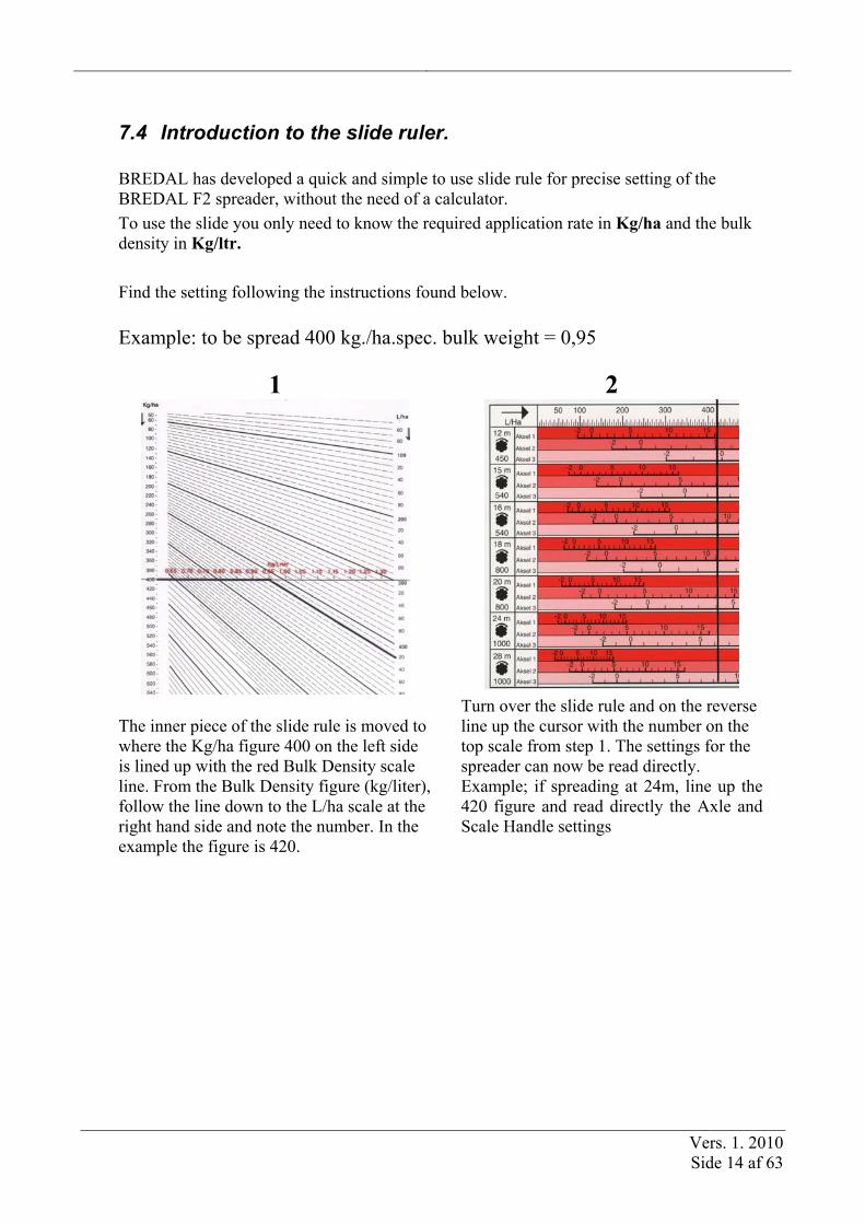
7.4 Introduction to the slide ruler. BREDAL has developed a quick and simple to use slide rule for precise setting of the BREDAL F2 spreader, without the need of a calculator. To use the slide you only need to know the required application rate in Kg/ha and the bulk density in Kg/ltr. Find the setting following the instructions found below. Example: to be spread 400 kg./ha.spec. bulk weight = 0,95
1 2
The inner piece of the slide rule is moved to where the Kg/ha figure 400 on the left side is lined up with the red Bulk Density scale line. From the Bulk Density figure (kg/liter), follow the line down to the L/ha scale at the right hand side and note the number. In the example the figure is 420.
Turn over the slide rule and on the reverse line up the cursor with the number on the top scale from step 1. The settings for the spreader can now be read directly. Example; if spreading at 24m, line up the 420 figure and read directly the Axle and Scale Handle settings

Vers. 1. 2010 Side 15 af 63
7.5 Max. Capacity per minute The V-belt transmission may not be overstressed. The output rate may not exceed more than:
• 250 kg/minute by 540 rev/min or • 300 kg/minute by 1000 rev/min.
The way of calculating the output rate is following: Km/h x Working width x kg/ha
600 = kg/minute
The maximum foreward driving speed can be calculated the following way: 180.000 Working width x kg/ha
= km/t (max)

Vers. 1. 2010 Side 16 af 63
8 Adjustments for spreading Damaged or very worn spreading vanes should be changed to new ones ! Spreading vanes with holes will throw the fertiliser in the wrong direction ! It is SOLELY the operator’s responsibility that spreading discs and vanes are correctly mounted. Check also the 2 downshutes (slopes for the fertiliser to fall down to the spreading discs), the downshutes must be free residues of fertiliser.
8.1 12 – 36 meter working width In order to spread between 12 and 36 metres, the spreader is equipped with spreading discs each with 6 spreading vanes. Listed in the Chart below are the settings of the Downchutes and the Pto Speed for spreading in the field.
Spreading in the Field
A 2X 1
12 m 0 450
15 m 1 540
16 m 1 540
18 m 2 600
20 m 2,5 700
24 m 4 900*
28 m 4 1000*
30 m 4,5 1000*
32 m 5 1000*
36 m 5,5 1000*
1
½
*Prilled fertiliser max 800 rpm.
12-36 m

Vers. 1. 2010 Side 17 af 63
Please note that the gear-selector must be placed on 1
2x1 = The setting is for both downchutes
8.2 Headland spreading on 12-28 meter
When engaging the Headland spreading system, the revolutions of the left spreading disc are reduced by approximately 50%
The gear-selector on the spinner box is set on ½, which reduces the revolutions of the left spreading disc (towards the headland) - the right spreading disc, into the field, continues with full revolutions.
The Downchutes and Pto speed are adjusted according to the below chart, and it is neces-sary to drive with the left spreading disc towards the headland i.e drive clockwise around the field boundary.
The chart below has the settings for 12-28 m headland spreading
Headland spreading on 12-28 m
Listed in the chart below the settings of the downshute and Pto speed for headland spread-ing on 12-28 m.
A ½
1
12 m 4,0 ½ 400
15 m 4,0 ½ 450
16 m 4,0 ½ 500
18 m 5,0 ½ 650
20 m 5,0 ½ 750
24 m 5,5 ½ 950
28 m 6,0 ½ 1000
Note that the gear selector MUST be set for Headland spreading

Vers. 1. 2010 Side 18 af 63
If you require the full rate toward the headland to optimise yield, increase on the chart with the Pto speed, the figure by up to 100 revolutions/minute where possible. If you require no spreading beyond the headland for environmental considerations, reduce the chart Pto speed figure by up to 100 revolutions per minute.

Vers. 1. 2010 Side 19 af 63
8.3 Headland spreading on 28-36 meter
When engaging the Headland spreading system, the revolutions of the left spreading disc are reduced by approximately 33%
The gear-selector on the spinner box is set on headland, which reduces the revolutions of the left spreading disc (towards the headland)
The downcute and Pto speed are adjusted according to the below chart, and it is necessary to drive with the left spreading disc towards the headland.
If the machine is mounted with downcutes that has a small hatch, the hatch on the downcute towards the headland (Left side) must be opened while spreading headland spreading.
Headland spreading 28-36 m
Listed in the chart below the settings downcute and Pto speed for headland spreading on 28-36 m.
A ½
1
28 m 6,0 ½ 650
30 m 6,0 ½ 700
32 m 6,0 ½ 800
36 m 6,5 ½ 900
Note that the gear selector MUST be set at Headland spreading
If you require the full rate toward the headland to optimise yield, increase the chart Pto speed figure by up to 100 revolutions/minute where possible. If you require no spreading beyond the headland for environmental considerations, reduce the chart Pto speed figure by 100 revolutions per minute, and reduce the application rate by 10%.

Vers. 1. 2010 Side 20 af 63
9 Trouble shooting
WARNING !!! • The spreading vanes must always be mounted correctly on the discs. • Incorrectly mounted vanes may cause large changes in the spread pattern.
Correct mounting
Responsibility!!! • Damaged or very worn spreading vanes should be changed to new ones ! • Spreading vanes with holes will throw the fertiliser in the wrong direction ! • It is SOLELY the operator’s responsibility that spreading discs and vanes are correctly
mounted !
Guidance in adjusting the evenness of the spreading you will find under: Spread Test and adjustment of spreading

Vers. 1. 2010 Side 21 af 63
9.1 Incorrect balanced spreading.
If the spread pattern is not balanced to the left and right, or when there is too much fertiliser at the overlap on one side, first check that the spreading vanes are in good order ( not worn or bent ) and that they are correctly mounted, see fig. above. Also check that top link of the machine in the working position is in-between parallel with the lower link arms and the horizontal. If the angle of the top link is too steep, it greatly increases the risk of damaging the chassis frame of the machine. Check that the downchutes are clean with no material build up. Then check that the left and right feed gates have the same opening and distances as specified in section 8.2. Check that the downchutes are set at the same position for metering material to the same point on each spreading disc. To check this precisely, Bredal A/S offer a tool (a downchute measuring instrument) with instruction, that can be ordered.
If the spread pattern continues to be non-symmetrical, the 4 bolts on which the spreading disc transmission is mounted can be loosened and the whole transmission can be adjusted a little toward the side which spreads too little fertilizer. ( Approx. 0,5 – 1.0 mm for every % difference from the 50% that should be spread to each side).
9.2 Incorrect application rate If the spreader does not meter the correct application rate, follow the procedure below :
1. Check whether the Bulk Density of the fertilizer is correct. For this use the Bulk Density Kit to directly read the value ( see section 6.2 to zero the kit ).
2. Check whether the conversion from kg/ha to litre/ha is calculated correctly (section 6.3).
3. Check whether the landwheel turns evenly. If the landwheel bounces on the tractor wheel, the spreader will not meter correctly. This can be checked by driving a distance on a road without having fertilizer in the hopper – or by dismounting the PTO shaft between the landwheel and the 3-axled gearbox. The landwheel must run 55,5 revolutions per 100 metre forward travel of the tractor. A Mechanical counter is of assistance for this purpose (see extra equipment)
4. Check the setting of the rear doors and whether the side rubbers are correctly adjusted (see fig. 19): B = 40 mm at scale setting 8 and C = 112 -> 115 mm between the side rubbers at the slide opening. When checking measurement B, we recommend that you use a piece of steel or wood with the dimensions of 40 mm height and 112-115 mm width (C). You must be able to slide this under the rear door, without moving the side rubbers or rear gate.
.

Vers. 1. 2010 Side 22 af 63
B = 40 mm C = 110-115 mm
Fig. 19. Regulating rear door opening
The rear doors, connecting rods and the adjusting axle must run freely, otherwise the correspondence between scale settings and downshute opening will be incorrect. Particularly check that the pivot point ” T ” moves freely and is lubricated. Always move the handle down to the scale number when adjusting the rear doors.
If the spreader continues to meter incorrectly after the above checks have been carried out, then it is possible to adjust the mechanism to match the scale reading with the amount actually metered in practise. The adjustment rods on each regulating slide can then be used to correct the error. One digit on the scale corresponds to 2,5 mm movement of the rear door, which means that everytime the nut on the adjusting rod is moved 1,5 turns, the rear door is lowered/raised by 1 step on the scale (Fig 19).
Alternatively a static calibration test of application rate can be completed. For further instruction see section 15

Vers. 1. 2010 Side 23 af 63
10 Maintenance. The spreading system should be clean and intact. Worn out spreading discs or vanes may cause uneven spreading.
The side rubbers of the conveyor should be firmly pressed onto the conveyorbelt. The conveyor belts should be tensioned and run correctly. If one of the floorbelts is running so much out of line that the edge is catching on the frame, adjust by tightening or loosening the adjuster with a single nut. Turn the nut a maximum half turn and run the floorbelt to allow it to settle in the new position. Only adjust the belt tensioner with the two locknuts if the overall belt tension needs to be increased to prevent belt drive slip.
V-belts in transmission should be checked and tightened. It should not be possible to turn the discs in the same direction. Check by pushing against a vane on the left disc, while pulling a vane on the right disc. Loosen the belt tensioner lock nut, then tighten the belt tensioner until the discs just slip. Then tighten the adjuster one more full turn and retighten the locknut. Check after the first load then daily. ALWAYS CHECK TENSION WHEN THE BELTS ARE COLD!
Washing – after each usage the spreader should be washed and greased. Wash down from the hopper to the disc cover and to the discs/spinner box. After cleaning run the spreader for 2 – 3 min-utes to allow air movement to dry the surfaces. Storage: Before putting the machine away after the season it must be thoroughly cleaned to remove any fertiliser residue, all greasing points lubricated and the machine sprayed with a thin layer of oil. Use either a propriety protection oil or hydraulic oil, which are designed to be in contact with rub-ber components and are thin to give very good cover. However, remember to wipe off any excess oil from the floorbelts after application as oil on rubber may cause damage in the longer term. You can also cover the floorbelts with an absorbent material when spraying. The material should be re-moved after application and again the floorbelts wiped to remove any excess oil. The floorbelt drive wheel must be in the forward position with the least spring pressure when stored. The hydraulic cylinder is then fully closed to protect the piston rod and seals against dam-age. PTO shafts for both the spinner box and floor belt drives should be dismounted and the cross joints and telescopic tubes regularly greased

Vers. 1. 2010 Side 24 af 63
10.1 Replacing the V belts.
1) Spreadbox without V belts 2) V-belt around pulley 1 and 2
3) twist 180° and around pulley on headland gear
4) around thightening pulley and V-belt must be thightened.
5) Thightening on headland gear to be mounted with V-belts.
6) Bolt for thightener to be mounted with feder and thightened.To be thightened until feder has 45 mm left.
7) Changing fork and plast bearing 1 to be mounted
8) Handle and plastbearing 2 and 3 to be mounted
9) Feder guidance and feder to be mounted
10) Handle to be moved in mid-dle position and mount lock pin..

Vers. 1. 2010 Side 25 af 63
11 Fertiliser quality The F2 and F2W have a variable spread width from 12 to 36 metres At 540 Pto rpm, the fer-tiliser particles leave the vanes at approx. 130 kph (80mph) and at 1000 Pto rpm the speed is approx. 240kph (150mph). The fertiliser is therefore exposed to large centrifugal loadings to achieve these speeds. This means that particularly for the wider widths the fertiliser must be of high quality. The most important properties are: Particle strength: is measured by placing a fertilizer grain on an accurate digital scales and pressing down on the granule with , for example, with the flat end of a pencil. The weight which is shown when the particle shatters, is an indicator for the particle strength of the fer-tilizer. Be sure to try several granules (both big and small) and then calculate the average particle strength (fig.26). Particle strength decreases with humidity and will remain de-creased even if the material is dried again. Always keep fertiliser covered/sealed with plastic.
Fig. 26. Scale for measuring the particle strength
Fig. 26. Scale for measuring the particle strength
Particle Size: can be measured using the BREDAL Sieve Box. Fill up the space above the screen with the largest mesh. Put on the lid and shake until no more changes of distribution occur. Turn the box with the lid upwards. Measure the number of mm in each compartment. Find out the % distribution for each compartment (fig.27) and determine the Mean (average) Particle size. The smaller the mean size, the less wide the spread width. Bulk Density can be calculated from the weight in a litre measure or a 10-litre bucket. The greater the amount, the more precise the measure. BREDAL offers a Bulk Density kit mounted on the spreader which directly indicates the bulk density. (Instructions under sec-tion 6) Particle Shape can be judged visually. The smoother and rounder the granule, the better it flies in the air and the better it flows on the vanes. A very sharp edged particle (like broken stones) or a particle with a very uneven surface has poor aerodynamic properties and may have has difficulty reaching to larger working widths. High Dust Content is obvious if a large amount of material is gathered below the smallest sieve, but the dust content can often be judged visually. High dust content may limit the overall spread width and may cause build-up on vital parts in humid conditions
Vers. 1. 2010 Side 26 af 63
Standard settings of this machine a based on the following minimum requirements:
Working width Working
width Working width Working
width 12-16 m 12-16 m 12-16 m 12-16 m 18-20 m 18-20 m 18-20 m 18-20 m 24-28 m 24-28 m 24-28 m 24-28 m 30-36 m 30-36 m 30-36 m 30-36 m
12 Performing a spread test and adjustment of spreading. If there is concern that the machine is not spreading correctly or the fertilizer type being has other properties outside the parameters in Section 11, a Spreading Test is recommended. During the execution of the test it is important to consider the following points:
1. The test must take place under dry conditions ( field/machine)
2. The test must take place in a field with a good crop, about 10 cm of strong cover, so that bouncing particles or ricochets are avoided
3. Carry out the test on a flat part of the field and to place the trays carefully to be as horizontal as possible. The test must be completed using the same forward speed, which normally is used for spreading (optimum is 10 – 15km/h if the field conditions allow).
4. Worn out spreading vanes should be replaced.
5. Make sure to run about 100 to 200 kg fertilizer through the spreader before the test is carried out. There will always be a coating left from old fertilizer, other residue or rust on the discs and vanes of the spreader, which need to be worn off before the test to show a true picture of the spreading performance.
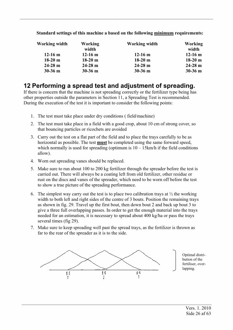
6. The simplest way carry out the test is to place two calibration trays at ½ the working width to both left and right sides of the centre of 3 bouts. Position the remaining trays as shown in fig. 29. Travel up the first bout, then down bout 2 and back up bout 3 to give a three full overlapping passes. In order to get the enough material into the trays needed for an estimation, it is necessary to spread about 400 kg/ha or pass the trays several times (fig 29).
7. Make sure to keep spreading well past the spread trays, as the fertilizer is thrown as far to the rear of the spreader as it is to the side.
Optimal distri-bution of the fertiliser, over-lapping.

Vers. 1. 2010 Side 27 af 63
1 2 3
Positions of the testing trays BREDAL recommends using 7 trays for testing.
.
12.1 Correction of the spread pattern
Fig. 30. Measuring Tubes:
Too much fertilizer between the tracks.
Fig. 31. Measuring Tubes:
Too much fertilizer behind the spreader.
Too much fertilizer between the tracks? (fig. 30 ) A. 12-16 m: Increase the Pto speed from 450 to 540 rpm at 12 m spread width and increase from
Pto speed 540rpm by 100 rpm per test at 15-16 metre until the spreading is corrected.
B. 18-28 m: The downshute scale (fig. 32) should be moved towards 0. If the initial test with standard settings is unacceptable, move the downshutes 1-2 full scale marks. If the second test shows that this was too much, the difference between the two tests will indicate how far the scale has to moved back.
C. 30-36 m: The downshute scale (fig. 32) should be moved towards 0. If the initial test with standard settings is unacceptable, move the downshutes 0,5-1 scale marks.
Too much fertilizer behind the spreader? (fig. 31) A. 12-16 m: Adjust the downshutes by increasing 2 scale marks per test until the test is correct. B. 18-28 m: Providing the fertilizer observes the requirements on particle strength and size (sec-
tion 11.2), increase the downshute scale setting by scale 1-2 full scale marks towards 9. C. 30-36 m: Providing the fertilizer observes the requirements on particle strength and size (sec-
tion 11.2), increase the downshute scale setting by scale 0,5-1 full scale marks towards 9.
Track Testtrays

Vers. 1. 2010 Side 28 af 63
If the particle strength and/or the grain size do not observe the requirements (stated under 11.2), the combination of tractor Pto speed and the downshute scale setting can be changed, as shown below:
Lower the tractor Pto speed by 20%. The spreading mechanism will then be more gentle on the fertilizer (lower particle strength requirement) and drop the fertilizer earlier, thus leaving more fer-tilizer between the tracks.
Should this not be sufficient, move the downshute scale one mark at a time towards 9. Be aware of the fact that this way of spreading is much more sensitive to fluctuations in the fertilizer quality, fluctuations in the distance between each bout and variations in the tractor Pto speed than the normal recommended standard settings. The overlap is significantly reduced because a box shaped spreading curve when compared to the normal double, double overlapping spread pattern.
Fig. 33. Spreading with little overlapping Fig. 34. Spreading with double,double overlapping

Vers. 1. 2010 Side 29 af 63
12.2 Performing a spread test with headland spreading. Place the trays as shown in fig. 35. Adjust the machine as mentioned under section 7. If the machine drops too much fertilizer over the boundary line; lower the number of revolutions with 50 rpm per test, until the spreading is acceptable. In the event of the opposite with too little fertilizer at the boundary line, the number of revolutions should be raised with 50 rpm per test
Fig. 35. Setting out of test trays at headland spreading The shown numbers are in metres. Position the remaining trays with B,C and D equal over the re-maining distance.

Vers. 1. 2010 Side 30 af 63
13 Spreading on narrow Widths When spreading narrow widths, for example if there is a narrow width remaining after work-ing across the tramlines of a field, the following procedure should be followed: If the narrow working width is 60% of the normal bout width, the missing working width will consequently be 40%. Half of this is 20%. Subtract this amount (20%) from the application rate of the two bouts ei-ther side of the narrow width remaining, as shown below.
When spreading narrow widths, for example if there is a narrow width remaining after work-ing across the tramlines of a field, the following procedure should be followed: Example: If the narrow working width is 60% of the normal bout width, the missing working width will consequently be 40%. Half of this is 20%. Subtract this amount (20%) from the application rate of the two bouts ei-ther side of the narrow width remaining, as shown below.
Tramline smaller than the normal tramline width between 1. and 2. tramline. Exampel: If there is a tramline where the working width is only 60% of the normal working width wich leaves 40% of the spread area. Then the application rate needs to be reduced by 40 on the 2 tramlines on each side of the re-duced tramline..
13.1 Spreading in hilly terrain If the areas are in a very hilly condition, then choose a high floorbelt speed and a low hight of the rear doors.

Vers. 1. 2010 Side 31 af 63
14 Driving to and from tramlines Spreading characteristic of Bredal F2 spreaders is to operate on a double, double overlap sys-tem of spreading, which produces a full half circle of spread with a very shallow tapering pat-tern In normal field work, this results in an accurate and even spread over a wide range of materi-als. To ensure that this eveness is maintained at headland boundaries, it is important to follow the technique shown in the diagrams below. The Bredal double, double overlap tapering pattern means that it is not necessary to shut off the feed to the right or left discs when approaching headland borders at an angle. By follow-ing the simple procedure in the diagrams, correct and even spreading of the whole field will be achieved with the normal single shut off control without the complexity of individual shut offs. Each diagram shows the point at which spreading should be shut off when approaching or leaving the headland at 90 degrees or at alternative angles. The shut off point depends on the angle of approach as shown on the diagrams and in each case is when the tractor rear wheels pass that point. When moving away from the headland, spreading should always be started when the tractor rear wheels pass the spread limit . . . shown as a dotted line (- - - ) on each diagram. Practise of this simple technique will ensure accurate and even application with minimum risk of over and under application and all by the simple operation of the single lever on/off control.
1 working . width(w.w.) ½ w.w.

Vers. 1. 2010 Side 32 af 63
14.1 Start and stop by 150
2/3 w.w. 1 w.w.
Towards headland tramline: Away from tramline:Disengage the metering system at a distance of 2/3 the working width from the headland tram-line. Slowly reduce the engine rpm before you disengage.
Engage the metering system at the working width from the headland tramline.
14.2 Start and stop by 300
1 w.w.
½ w.w.
Towards headland tramline: Away from tramline:Disengage the metering system at a distance of ½ the working width from the headland tramline. Slowly reduce the engine rpm before you disen-gage.
Engage the metering system at the working width from the headland tramline.

Vers. 1. 2010 Side 33 af 63
14.3 Start and stop by 600
1. w.w.
1/3 w.w.
Towards headland tramline: Away from tramline:Disengage the metering system at a distance of 1/3 the working width from the headland tram-line. Slowly reduce the engine rpm before you disengage.
Engage the metering system at the working width from the headland tramline.
15 Performing a static calibration test 1. Adjust the machine to the required application rate from the chart. 2. Dismount the spreading discs. 3. Put a minimum of 200kg in the hopper and turn the landwheel until there is an equal
amount of material all the way from the feed gates to the end of the floorbelt. 4. Place a tray or a bucket under each downshute. (It is necessary to place a piece of card-
board or similar under each downshute to form a chute in order to guide the fertilizer into the bucket).
5. Turn the landwheel 11.5 times, turning the wheel at normal operating speed ( about 1 revo-lution per second ).
6. Weigh the fertiliser collected from both feed belts. 7. Multiply the weight collected with the factor from the chart below for the selected working
width. The result is the number of kg/ha, which is applied.

Vers. 1. 2010 Side 34 af 63
Working width Factor meter 6 80 8 60 9 53,3 10 48 12 40 15 32 16 30 18 26,7 20 24 21 22,9 24 20 28 17,1 30 16 32 15 36 13,3 When this test is done, the cage wheel must turn with approx. the same speed as in a real situation. That means minimum 60 revs/min, equals 10 km/h wich gives 92 revs/minute on the cage wheel. 16 Special fertilisers
When spreading special fertilizer types, a spreading test with trays is always recommended. The details below should only be considered as guidance from Bredal.
16.1 N34 Prilled Ammonium Nitrate Nedenfor er anført indstillinger til spredning af N34. Der bør ikke køres med mere end 800 pto omdr., heller ikke ved spredning på 24 m. arbejdsbredde eller mere.
Der bør altid foretages en spredeprøve i marken ved spredning af N34.
Kun god kvalitet kan spredes på 24-28 og 30 m. arbejdsbredde.
Settings for N34
A
12 - 20 meter Standard settings 800 rpm
24 meter 5 800 rpm 28 meter 6 800 rpm 30 meter 7 800 rpm
16.2 Pure potash
This fertilizer, such as Muriate of Potash, is very coarse and angular, so runs very slowly on the spreading vanes. It may help improve the spread pattern result by increasing the downshute set-

Vers. 1. 2010 Side 35 af 63
ting by 2 or 2.5 marks higher than the normal recommended setting for the spread width. The settings of the downshute should be increased from the standard settings A
12 - 16 m 2 scale settings higher 18 - 24 m 3 scale settings higher Max 24 m. of working width by potash
Opposite to the normal rule of thumb, with this material it is important to choose the slowest floorbelt speed and the widest regulating slide opening from the chart.These materials run so slowly in the hopper that problems may be caused in keeping the regulating slides filled. It may be necessary to increase the regulating slide opening by approx. 10% compared with to the standard application rate setting guidelines.
16.3 Sulphate of Ammonia
By spreading of sulphate Ammonia the downshute settings must be higher than the standard settings.
12-16 m. working width 2 scales higher højere
18-24 m. working width 3 scales higher
24 m. working width is maximum for Sulphate of Ammonia .
16.4 Prilled Urea 9-12 m. working width: The tractor PTO speed may be increased up to 650-700 revolutions per minute if the particle strength is 1-1,5 kg minimum. 15-18 m working width: It is possible to achieve acceptable spreading on overall working width, but not with double overlap. The settings of the downshutes should be at scale 5, and the tractor Pto speed de-termined by a spread tray test , to match the type of Urea and the working width. 20-24 m. working width: Folow the procedure for 15 – 18m – however the particle size should be minimum of mean 2 mm. The tractor Pto speed must be accurately maintained, as it correspond exactly to the working width.
Always carry out a spreading tray test before spreading Urea.

Vers. 1. 2010 Side 36 af 63
16.5 Granulated Urea Granulated Urea has a rougher surface than prilled urea and normally is supplied with a mean particle size of 3 –3.5 mm and particle strength of 2-3 kg. The standard settings of the spreader should be used for up to 24 metre working width. However the tractor Pto speed should not exceed 800 rpm if the particle size is 2 mm or less. To compensate for reducing the tractor Pto speed at the wider working widths, the spreader should be raised as high as possible (spreading disc height 110 cm). Always carry out a spreading tray test before spreading Urea.

Vers. 1. 2010 Side 37 af 63
17 Spreading of Slug Pellets, Rape and Mustard When spreading slug pellets, rape or mustard seeds the Reduction Kit must be fitted under the regulating slides. When in position as shown below, the regulating slides are lowered to firmly hold the Reduction Kit in position, but not pressing too tightly on the floorbelts.
Slug pellet kit.
Spreading of Slug Pellets: An application rate of approx. 4 kg/ha is applied at 1000 tractor Pto speed, using Axle 1 at 24 m working width. Spreading of Rape and Mustard seeds. The application rates available using the Reduction Kit are as follows: • 5 kg/ha in Axle 1. • 10 kg/ha in Axle 2. 20 kg/ha in Axle 3. A static calibration test can be made in order to check the actual metered amount, see section 14 Max working width is 16-18 m., optimum is 10 – 12 m. at 800 rev/min on the pto.
The following only applies to the spreading of rape and mustard: • Move the downshutes to scale mark 0
• Rape runs very freely on the vanes, as it is very smooth, and therefore the downshutes must be set as described. Even at this setting the machine may apply a slightly higher rate in between the tracks than behind the ma-chine..

Vers. 1. 2010 Side 38 af 63
18 Spreading of slug pellets (only for F2 and F2W with hydrau-lic rating) Bredal recommend not to go further than 24 m and also not to spread these special seeds under windy conditions. When spreading rape, mustard a.o. the best results are obtained on 12-18 m under calm wind con-ditions. Settings by spreading: The rear doors must be closed as much as possible wich will corrospond to a scale of 50. Materialet der ønskes spredt, afvejes med litervægten, og værdien aflæses. The downshutes are set to 0. Programming
Esc
Hovedmenu
Menu
Dos. / indstillingVejning
IndkodningInfo
Tømning
SystemData / Print
In the menu App. Rate setting the following must be put in:
- Setting af the scale on 50 - Spez. Weight of the material to be
spread.. - Working width - Kg / ha - Downshute position (only on certain
versions) PTO speed: - spreading of Rape, mustard a.s.o.. - spreading slug pellets
800 RPM Same settings as by fertiliser.
Even though recommendations for a correct application and spreading are followed, Bredal still would like to emphasize that a spread test is done in order to ensure the best possible result.

Vers. 1. 2010 Side 39 af 63
19 Late application
Late application can be done in 2 ways:
1. The best distribution of the fertiliser is optained by raising the spreader as high as possible (110 – 120 cm above the ground). The drop hight of the fertilser must only be 25 cm for ob-taining a good distribution. That is why it´s posible to spread in crops with a hight of 70 to 80 cm with the late application equipment with a good result. Be aware of not to damage the blades of the crops. Use standard settings when using the late application equipment.
2. With late application equipment, it´s possible to spread in crops in the same hight as the hight of the spread discs. The late application equipment is mounted on the arms holding the safety guards. It´s important that the equipment is mounted total horizontally.
3. Always follow below recommendations with late application set mounted.
Settings for 12-36 m late application
A
12 m 0 350
15 m 0 450
16 m 0 450
18 m 1,5 600
20 m 1,5 600
24 m 2 700
28 m 3 800
30 m 4,5 850
32 m 5 850
36 m 6 850
1
½
2 X = right and left downshute
Prilled fertiliser + 2 scale steps on the downshutes
12-36 m
2 X

Vers. 1. 2010 Side 40 af 63
20 F2W with hydr rating and load cell

Vers. 1. 2010 Side 41 af 63
F2W with hydr. Rating and load cell
C
Esc
Menu
Jan. 2010
Type KF 4
2
3
1
5
678
Pos. Beskrivelse
1 Start-/Stop key 2 Load key 3 MENU key 4 Piletaster 5 Return (enter) key 6 Escape key 7 Clear key 8 Program keys

Vers. 1. 2010 Side 42 af 63
20.1 Symbol selection
+
+ T
Km/h Area RPM PTO Kg Calibration Filling Kg/min. Save Kg/ha RPM Oilmotor Ton
10%
10%
AUTO
Time Kg left +10% -10% Right Left Light turns on by pressing any key. Turn on light contrast - contrast + Working width
100 m
Alarm OFF Alarm ON Wheel tractor Wheel spread-er Radar Speed autoca-libr. Reg. down Reg. up Next page Last page Headland spreading
Vers. 1. 2010 Side 43 af 63
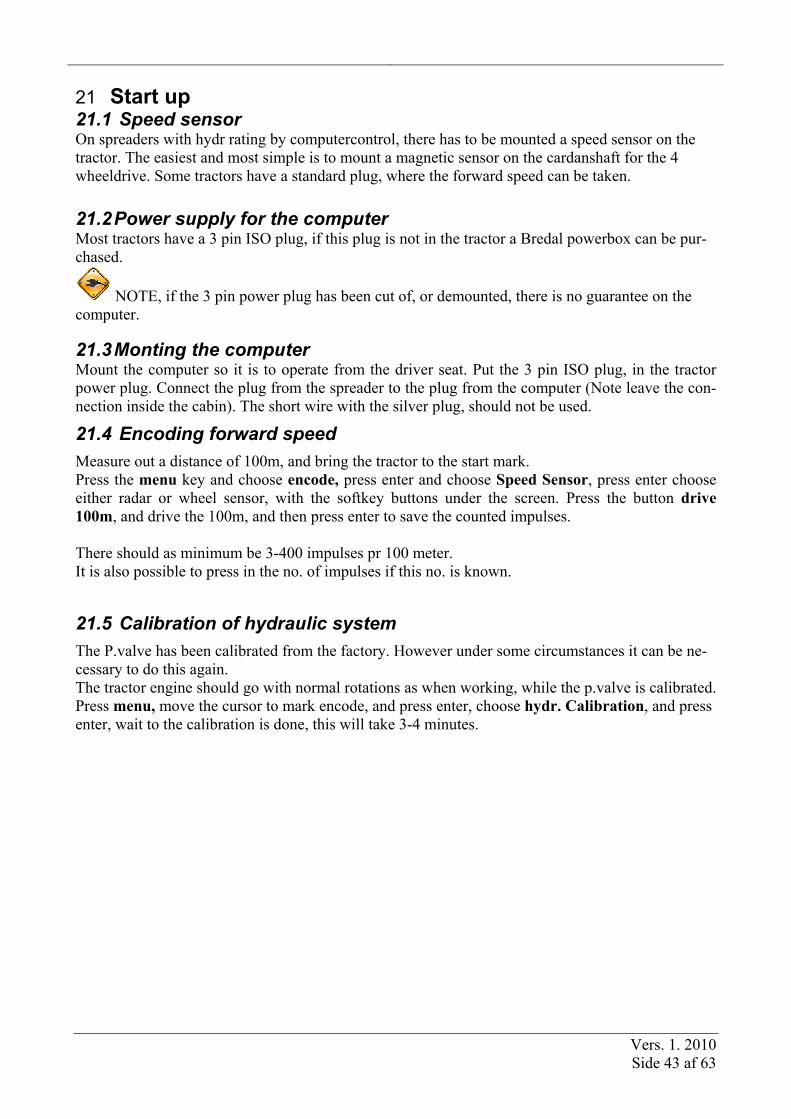
21 Start up 21.1 Speed sensor On spreaders with hydr rating by computercontrol, there has to be mounted a speed sensor on the tractor. The easiest and most simple is to mount a magnetic sensor on the cardanshaft for the 4 wheeldrive. Some tractors have a standard plug, where the forward speed can be taken.
21.2 Power supply for the computer Most tractors have a 3 pin ISO plug, if this plug is not in the tractor a Bredal powerbox can be pur-chased.
NOTE, if the 3 pin power plug has been cut of, or demounted, there is no guarantee on the computer.
21.3 Monting the computer Mount the computer so it is to operate from the driver seat. Put the 3 pin ISO plug, in the tractor power plug. Connect the plug from the spreader to the plug from the computer (Note leave the con-nection inside the cabin). The short wire with the silver plug, should not be used.
21.4 Encoding forward speed
Measure out a distance of 100m, and bring the tractor to the start mark. Press the menu key and choose encode, press enter and choose Speed Sensor, press enter choose either radar or wheel sensor, with the softkey buttons under the screen. Press the button drive 100m, and drive the 100m, and then press enter to save the counted impulses. There should as minimum be 3-400 impulses pr 100 meter. It is also possible to press in the no. of impulses if this no. is known.
21.5 Calibration of hydraulic system
The P.valve has been calibrated from the factory. However under some circumstances it can be ne-cessary to do this again. The tractor engine should go with normal rotations as when working, while the p.valve is calibrated. Press menu, move the cursor to mark encode, and press enter, choose hydr. Calibration, and press enter, wait to the calibration is done, this will take 3-4 minutes.
Vers. 1. 2010 Side 44 af 63
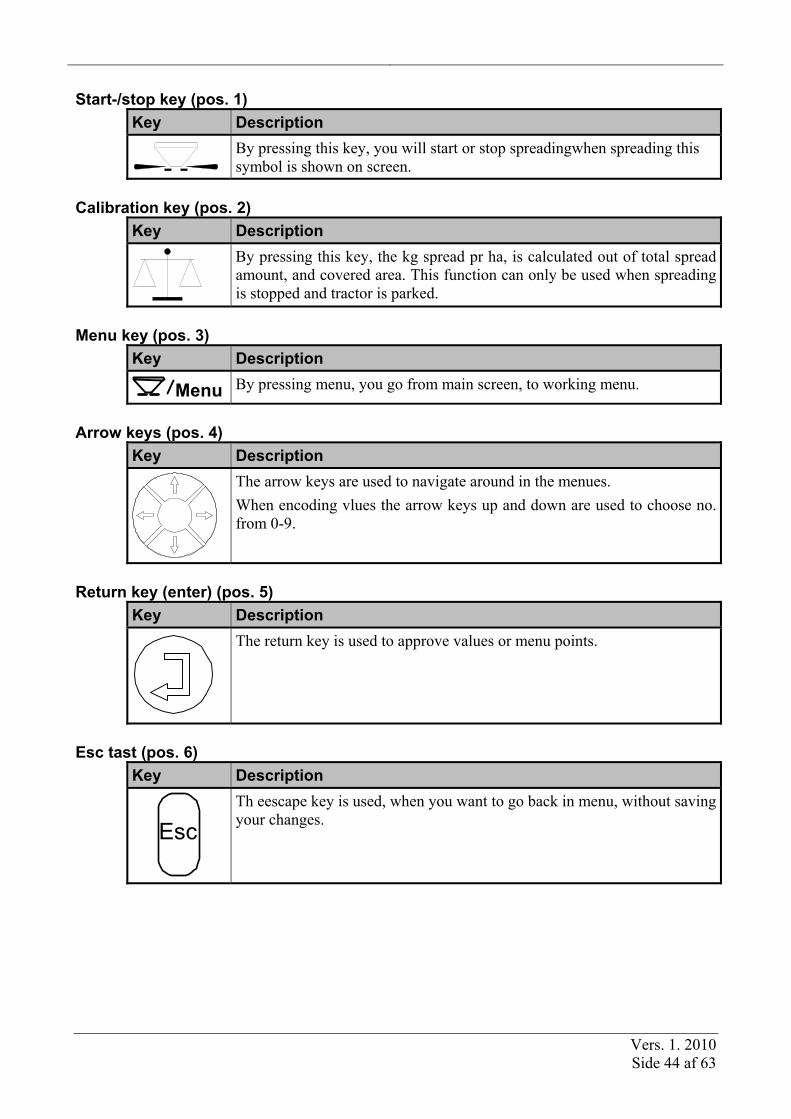
Start-/stop key (pos. 1) Key Description
By pressing this key, you will start or stop spreadingwhen spreading this symbol is shown on screen.
Calibration key (pos. 2)
Key Description
By pressing this key, the kg spread pr ha, is calculated out of total spread amount, and covered area. This function can only be used when spreading is stopped and tractor is parked.
Menu key (pos. 3)
Key Description Menu
By pressing menu, you go from main screen, to working menu.
Arrow keys (pos. 4)
Key Description
The arrow keys are used to navigate around in the menues. When encoding vlues the arrow keys up and down are used to choose no. from 0-9.
Return key (enter) (pos. 5)
Key Description
The return key is used to approve values or menu points.
Esc tast (pos. 6)
Key Description
Esc
Th eescape key is used, when you want to go back in menu, without saving your changes.

Vers. 1. 2010 Side 45 af 63
Clear key (pos. 7)
Key Description
C
The clear key is used to reset values, and to confirm alarms.
Program keys (softkeys) (pos. 8)
Key Description
taste 1 - 4
The function of the program keys are shown in the operation screen. Each function is shown on the screen, directly above the actual key.
22 Operation The operation screen is displayed when you press the MENU key, no matter where you are in the program. The operation screen is the first thing displayed when the device is switched on. Correct operation requires that all data entry/calibration has been carried out.
22.1 Operation screen The operation screen is divided into the following sections. These sections are described below.
State of the spreader
+
XX% X.XX X.X
+
XX%
-
XX%
The arrows shows whether the app. Rate is being increased(up arrow) or decreased (down arrow)
Step app rate status App. Rate shown in kg/ha
Operation function 2 (selectable)
Step app rate: + = increase. - = decrease
Change operation func-tion 2.
State of spreader
Shows whether the spreader is in function or not.
Step app. rate The application rate can be change in increments equivalent to the number of per cent chosen under settings. If the +/- step application rate keys are activated, these are shown on the display, along with the percentage amount the application rate has been changed by. The size of the increments is the same for both + and – stepping.
Vers. 1. 2010 Side 46 af 63
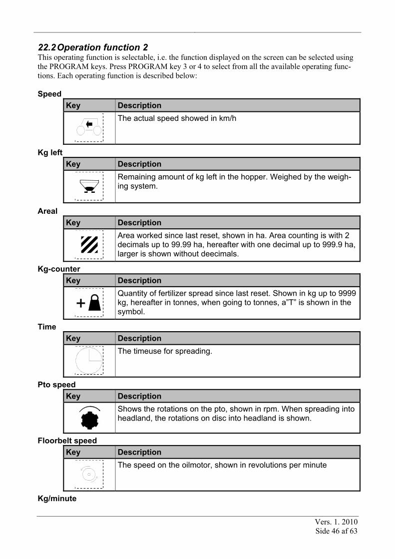
22.2 Operation function 2 This operating function is selectable, i.e. the function displayed on the screen can be selected using the PROGRAM keys. Press PROGRAM key 3 or 4 to select from all the available operating func-tions. Each operating function is described below: Speed
Key Description
The actual speed showed in km/h
Kg left Key Description
Remaining amount of kg left in the hopper. Weighed by the weigh-ing system.
Areal Key Description
Area worked since last reset, shown in ha. Area counting is with 2 decimals up to 99.99 ha, hereafter with one decimal up to 999.9 ha, larger is shown without deecimals.
Kg-counter Key Description
Quantity of fertilizer spread since last reset. Shown in kg up to 9999 kg, hereafter in tonnes, when going to tonnes, a”T” is shown in the symbol.
Time Key Description
The timeuse for spreading.
Pto speed Key Description
Shows the rotations on the pto, shown in rpm. When spreading into headland, the rotations on disc into headland is shown.
Floorbelt speed Key Description
The speed on the oilmotor, shown in revolutions per minute
Kg/minute

Vers. 1. 2010 Side 47 af 63
Key Description
The quantity being spread shown in kg/min.
22.3 Hydraulic change of headland gear (Optional equipment) When the spreader is equipped with hydraulic controlled change of headland gear, the headland gear will be activated through a double hydraulic outlet on the tractor. When the headland spreading is active, a symbol is visible in the upper left corner of the screen (only for spreaders with hydraulic change of headland gear). The pto axle has to have stopped before you can change to and from headland gear.
When this symbol is shown, you have an acti-vated headland gear. No symbol is shown, if the spreader is bought without hydraulic activation of headland gear..
Menu
10% 10%
30010%
C
Esc
+8250

Vers. 1. 2010 Side 48 af 63
22.4 Calibration of the application rate
By pressing the calibration key, it is possible to make an average calibration of the total spread do-sage since last calibration. The average dosage is calculated out of the amount spread, and the weighed amount.
The averagr application is calculated like this (with load cells):
Step/key Description
1
Press CALIBRATION key, and this screen will occur:
Calculated XXXXWeighed XXX Actual flow factor New flow factor
X.XX
App. Rate Kg/ha
2
Press the filling key (softkey) to start a new calibration.
3. Spread a suitable amount (depending on wished application)
3
By pressing weighing (softkey) the average dosage is being re cal-culated, and the computer will suggest a new flowfactor.
4
If the new flow factor is acceptable Press the save (softkey), and the new flowfactor is saved. The spreader is weighing automaticly and spreading can continue.
5. Menu
If the new flowfactor is not acceptable: Press the MENU-key and continue spreading, until a larger amount has been spread.

Vers. 1. 2010 Side 49 af 63
22.5 Calibration without load cells
Step/key Desription
1
Press the CALIBRATION key, and this screen will occur:
Calculated XXXXWeighed XXX Actual flow factor New flow factor
X.XX
App. Rate Kg/ha
2
Press the filling button, and enter the amount loaded. This are done when loading the spreader
3
When the application rate are calculated, press the weighing (soft-key) and the actual amount left in the hopper is entered.
4
A new flow factor is automaticly being calculated by pressing save (softkey).
Vers. 1. 2010 Side 50 af 63
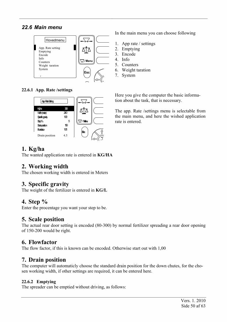
22.6 Main menu
Esc
Hovedmenu
Menu
Dos. / indstillingVejning
IndkodningInfo
Tømning
SystemData / Print
In the main menu you can choose following 1. App rate / settings 2. Emptying 3. Encode 4. Info 5. Counters 6. Weight taration 7. System
22.6.1 App. Rate /settings
Esc Menu
App. Rate Setting Specific gravity 1.00 Kg/ha Width (meter) 24.0 300
Step % 5Skale position 150Flowfaktor 1.05
Here you give the computer the basic informa-tion about the task, that is necessary. The app. Rate /settings menu is selectable from the main menu, and here the wished application rate is entered.
1. Kg/ha The wanted application rate is entered in KG/HA 2. Working width The chosen working width is entered in Meters 3. Specific gravity The weight of the fertilizer is entered in KG/L 4. Step % Enter the procentage you want your step to be. 5. Scale position The actual rear door setting is encoded (80-300) by normal fertilizer spreading a rear door opening of 150-200 would be right. 6. Flowfactor The flow factor, if this is known can be encoded. Otherwise start out with 1,00 7. Drain position The computer will automaticly choose the standard drain position for the down chutes, for the cho-sen working width, if other settings are required, it can be entered here. 22.6.2 Emptying The spreader can be emptied without driving, as follows:
Drain position 4.5
App. Rate setting Emptying Encode Info Counters Weight taration System

Vers. 1. 2010 Side 51 af 63
Step/Key Description 1 Menu
Press the MENU-key.
2 Move the cursor, by the up or down arrows, and choose emptying 3 Press the enter (return) key 4
You can now empty the spreader, by pressing the start/stop key.
22.6.3 Encode The encode menu is selectable in the main menu, by using the arrow keys, to move the cursor, and the enter key to select. 22.6.3.1 Alarms Encoding of alarms, is chosen in the encode menu, by highligting Alarms, and press enter. Those alarms available are turned on and off with the softkeys. To confirm reading off an alarm, press C (clear)
Key Description
Alarm activated
Alarm off.
Kg left alarm Alarm ON/OFF and the no of kgs you want to have an alarm at.
Rpm disc alarm Alarm ON/OFF and the minimum rotations on the disc you want the alarm given. 22.6.3.2 Speed sensor Selectection of speedsensor and calibration figure for speedsensor is encode here. It is also possible to calibrate the speed sensor. This is selected in this menu, by chosing Speed sensor.
Key Description
By pressing (softkey 1) you will select radar as speed sensor (7 pin DIN/ISO plug) If the no. of impulses pr 100m is known, this no. can be encoded..
By pressing (softkey 2) you choose Wheelsensor mounted on trac-tor, as speedsensor. By the 7 pin DIN/ISO plug. If the no. of impulses pr 100m is known, this no. can be encoded...
By pressing (softkey 3) you select wheelsensor on spreader, as speedsensor through the 21pin plug. If the no. of impulses pr 100m is known, this no. can be encoded.

Vers. 1. 2010 Side 52 af 63
Automatic speed calibration
Step/key Description 1 Measure out a 100m distance, and go to startmark. 2 Select speed sensor as described above.
3
Press this key, and drive the 100m, the computer will count the impulses as you go.
4 Press enter to accept the calibration of the speed sensor.

Vers. 1. 2010 Side 53 af 63
22.6.3.3 Hydraulic calibration
It is not normally necessary to calibrate the proportional valve. Calibration has been done at the fac-tory. However, if there are problems with the hydraulic system it may be necessary to calibrate again. Select this menu from the settings menu by selecting “Hydr. calibration” using the UP and DOWN arrows. Then press the ENTER key. The procedure for calibrating the proportional valve is as follows:
1. The hydraulic oil must be at normal operating temperature and the spreader must be empty.
2. The tractor motor must be running at normal operating speed. Press the ENTER key. 3. The cell wheel will run up to maximum speed, and the speed will then be reduced until
the cell wheel stops. 4. Once calibration is finished, the display returns to the calibration menu. If the hydrau-
lic motor is unable to reach a minimum speed of 500 RPM, an alarm is raised. 22.6.3.4 Application rate calibration
Application rate calibration has normally been carried out at the factory and does not need to be done by the user. It will only be necessary to do it in special circumstances. Select this menu from the settings menu by selecting “App. Rate calibration” using the UP and DOWN arrows. Then press the ENTER key. For operational accuracy, the number of cm3 which is released per pulse needs to be set. If the quan-tity released per pulse is known in advance, it can be set directly. Otherwise the quantity released per pulse can be automatically calculated by calibrating the system as follows:
1. Select “New calibration” and press the RETURN key. 2. Enter the specific gravity (density) of the fertilizer (very important). 3. Press the ENTER key and the cell wheel is made ready (the cell wheel rotates and is
filled with fertilizer). 4. Empty the spill tray. 5. Press the START/STOP key to start the calibration (the cell wheel will turn). 6. Once a sufficient quantity has been released, stop the cell wheel by pressing the
START/STOP key. 7. Weigh the quantity released and enter the weight. 8. Press the ENTER key and the app. rate calibration is complete.
22.6.3.5 Weighing The weighing system is normally calibrated from the factory, so normally it is not necessary to make a calibration of this. If the weighing is not right, it is possible to make a new calibration.
Step/Key Description 1 Menu
With an empty spreader, press Menu.
2 Move the cursor by the up and down keys, to Weighing. 3 Press enter 4 Move the cursor by the up and down keys, to Calibration. 5. Press enter, and following warning will be shown.

Vers. 1. 2010 Side 54 af 63
Warning
Continue cal. ? Are you sure ?
ESC = exit
Calibration
When you want to calibrate the weighing system, press enter.
6. With empty spreader and no rpm on the pto, press enter and the system will be reset.
7.
Put a known weight in the hopper and encode this weight in kg. And press enter A new calibration figure is being calculated, and the calibration is through.
Calibration figure If the calibration figure is known, this can be entered directly, by selcting Calibration Figure, and entering the known figure, with the arrow keys, and press enter.

Vers. 1. 2010 Side 55 af 63
22.6.4 Info The information menu displays an overview of the various settings, and can be accessed from the main menu (press the MENU key). Then use the UP and DOWN arrows to select “Info”, and press the ENTER key.
C Esc Menu
Info App. Rate (Kg/ha) 300
24.0 Width (meter) Scale 1.19 Skala position 150 Flowfactor 1.19 Max. Kmt 17.5 Min. Kmt 3.2
In the info menu, it is possible to get a quick view of the most basic informa-tion. 1. App. rate 2. Working width 3. Specific gravity 4. Scale position 5. Flow factor 6. Max. Km/h 7. Min. Km/h
22.6.5 Counters It is possible to have up to ten different trip counters (jobs) in operation, which can be started and stopped, for example, when changing to another field. The trip counter menu can be accessed from the main menu (press the MENU key). Then use the UP and DOWN arrows to select “Trip counter”, and press the ENTER key. When you start a new job, the counters are reset. If you change to another job, and then change back again to the first job, the counters will continue counting from their previous values. Jobs can be reset individually.
This screen is showed when the menu point counters is selected.
Trip counters Print Trip counters Total counters Save counters
Counters

Vers. 1. 2010 Side 56 af 63
Tællerne i en opgave
New counter Delete counter
Kg X Area X.XX Time X:XX
Trip counter
1/10 This window is displayed when you se-lect the “Trip counter” menu. The in-dividual counters are described below: Beside the mentioned functions it is also possible to name the different counters, (letters are selected with ar-row keys)
Kg: The total number of kg spread since the job was started or last reset. Area: The accumulated area worked since the job was started or last reset. This area corresponds to the ef-fective area, i.e., only the area which has been spread. Time: The total effective time spent since the job was started or last reset.
Start/continuing a task
When you select the “Trip counter” menu, the last job you accessed is re-opened. If this is the very first job you are starting, job one will be opened.
Counter no 1Counter no 2Counter no 3Counter no 4Counter no 5Counter no 6
Trip counter To start or continue another job, press the “New counter” key. You can then select between jobs 1 – 10 by using the UP and DOWN arrow keys to high-light the desired number. Then press the ENTER key. To return to the operation screen, press the MENU key.
Resetting a task
If you want to reset the counters for a job, select the job as described above, and then select “Delete counter” and press the ENTER key. When menupoint Counter X is selectedNår menupunktet Tæller X vælges, vises automatisk det sidst anvendte sæt triptællere. Der er nu følgende muligheder: Der kan tælles videre i det valgte sæt triptæller (de aktive).
Vers. 1. 2010 Side 57 af 63
The counters will stay active until you select a new. Through the menupoint New Counter you can choose up to 10 different trip counters.
Deleting data in counters With the arrow keys choose delete counter, and press enter. The chosen counter will be deleted.
New counter Delete counter
Kg X
Area X.XX
Time X:XX
Trip counter
1/10
Kg (A.) = Exact weight counted by the load system. A correct counting will on-ly occur when using the Calibration of application, for all fertilizer spread in the field. Kg (B.) = Calculated weight by the im-pulses from the application unit.
Counter no 1Counter no 2Counter no 3Counter no 4Counter no 5Counter no 6
Trip counter New counter: The cursor placed on the counter you want active, and press enter. Now data will be saved in the selcted counter.
The different counters are numbered, but it is also possible to name the dif-fernt counters.
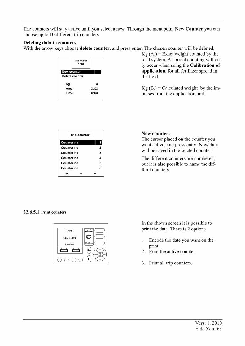
22.6.5.1 Print counters
C
Esc
Menudd-mm-yy
26-06-03
1 1-10
In the shown screen it is possible to print the data. There is 2 options 1. Encode the date you want on the
2. Print the active counter 3. Print all trip counters.

Vers. 1. 2010 Side 58 af 63
Trip counter
Init
1/10
Time XX
XX:XX Area (ha) XKg (A.)
Kg (B.)
Example
22.6.5.2 Total counters In this menu, you can see total counters, counting total amount of kg’s spread, total area spread, to-tal time spend spreading. 22.6.5.3 Save counters Here there is 2 options, you can either choose to save the counters in a HTML file, (shown by inter-net). Or in a CVS file, this file can be opened in an excel sheet. Move the cursor to the wished for-mat, and press enter. 22.6.6 Weight Taretion The weighing menu is selected in the main menu, by pressing the Menu key, and using the up and down arrows to mark and the enter key to select.
22.6.6.1 Tare The spreader has to be empty and the pto has to be stopped to make a taretion.
To make a taretion (reseting) the weighing system, select Tare and press enter 2 times, now the weighing system is tared. 22.6.6.2 Tare Frequency xxxxx
With the load system it is possible to: Show the actual kgs in the hopper, to calculate the average dosage, out of the fertilizer spread and the ha driven. 22.6.7 System The system menu can be accessed from the main menu (press the MENU key). Then use the UP and DOWN arrows to select “System”, and press the ENTER key.

Vers. 1. 2010 Side 59 af 63
22.6.7.1 Contrast/light
Key Description
Press this program key to make the display brighter.
Press this program key to make the display darker.
Press this program key to activate the auto light feature. The dis-play light turns off, and turns on automatically when any key is pressed.
Use this key to turn the display light on and off.
22.6.7.2 Language This option allows you to choose the working language for the LH Bredal 500 com-puter. Select your language and press softkey no 3, to confirm. 22.6.7.3 Speed simulation It is possible to simulate a speed, for example when troubleshooting or when you wish to spread in-dependent of the driving speed. You can enter the desired simulated speed in km/h, with 1 decimal place. The speed simulation can be started and stopped using Softkeys 1 & 2.

Vers. 1. 2010 Side 60 af 63
22.6.7.4 Test
C
Esc Menu
Test Input
0 % P. Ventil Headland gear
Valg af test input, kant/nedløbsposition eller P. Ventil
Test input Use the test input feature if, for example, you believe a sensor may be defective. For each input, there is a counter shown on the right side of the display which indicates the number of times that input has been activated (the counter resets automatically when you leave the “Test Input” menu, or if you press the C key). On the left side, the instantaneous status of the input is shown (Hi/Lo). You can page through the inputs by pressing the UP and DOWN arrows (2 pages in total). The input names displayed correspond to the following items:
Input Description Wheel DIN/ISO
Speed signal from the wheel sensor installed on the tractor (via the 7-pin DIN/ISO connector in the tractor).
Radar DIN/ISO
Speed signal from the radar installed on the tractor (via the 7-pin DIN/ISO connector in the tractor).
RPM cell wheel
Signal from the RPM sensor mounted near the cell wheel.
Press the DOWN arrow key to see the next set of inputs: RPM disc Signal from the RPM sensor mounted near the discs. Weighing Signal from the weighing system.
Press the UP arrow key to see the first set of inputs: Test headland gear
C Esc
Menu
Test Headland spreading
1+
0 HI Imp. Gear 1: Hydraulik Gear
In the shown screen, the hydr valve for the headland gear can be tested. In top it is shown if the sensor for the gear is giving impulses when activated.

Vers. 1. 2010 Side 61 af 63
C
Esc
Menu
Gear faktor
50 %
Indtast gear faktor 10-99%
= Gem
In the shown screen, there decreasing percen-tage, for the headland gear is shown 12-28 m Headland spreadning = 55 % 28-36 m Headland spreadning = 33 %
Test p. ventil In order to test the hydraulic motor’s proportional valve, you must specify a “duty cycle %”. Enter the desired duty cycle percentage, and then press the ENTER key. .
23 Operation alarms Situations can arise during operation that cause an alarm to be raised. The various alarms can be ac-knowledged by pressing the C key.
Carefully investigate why an alarm occurred before acknowledging the alarm. Below is an explanation of the “standard” alarms which can occur:
Application rate is outside
the possible range: Max. Flow exceeded: Min. RPM for the cell
wheel not reached:
+
XX% X.XX
X.X
+
XX%
-
XX%
Alarm
Regulatin outside rate area
+
XX% X.XX
X.X
+
XX%
-
XX%
Alarm
Max. Flow exceeded
P. Ventil kalibrering
Kalibrering udføres
Alarm
Min. RPM for the cell wheel not reached
The desired app. rate cannot be reached with the current settings and driving speed. Slow down, and the alarm will automatically disappear.
The maximum flow rate for the spreader has been ex-ceeded, slow down or change the app. rate setting.
The minimum rotating speed for the cell wheel (500 RPM) cannot be reached. This alarm is only displayed during calibration of the hy-draulic motor.

Vers. 1. 2010 Side 62 af 63
24 System plans
1
2
3
4
5
6
7
8
9
1011
12 +12V sensor
13
14
15
16
17
18
19
20 Nc
21 Nc
22
1
2
3
45
6
7
ISO-in-1 Radar
ISO-in-3 (Not active)
ISO-in-4 Implement in-work/out-of-workISO-in-5 (Not active)
+12V suplly
Ground
+
-
small pin
+12V power
0V power
Nc
Nc
Esc
C
Menu
Power
DIN 9684-1ISO 11786
In-7 RPM Hydr. Motor
Description
ISO-in-2 Wheel
Description
+12V elektronic
Pin No.
Pin No.
Pin No. Description
In-1 Weighing
In-2 RPM disc
In-4 Wheel spreader
In-5 Extra
Out-1, PWM to P. Valve (lo-side sw.)
Ground sensor
In-8 Extra
Out-7 +12V to P. Valve (hi-side sw.)
In-3 Border function (Fertilizer outlet pos.)
In-6 Gear pos.
Out-4 Gear (lo-side sw.)
Out-6 Gear (hi-side sw.)
Out-2 Actuator (lo-side sw.)
Out-3 Actuator (lo-side sw.)
Out-5 Actuator (hi-side sw.)
Out-8 Actuator (hi-side sw.)

Vers. 1. 2010 Side 63 af 63
Bredalsamleboks
Menu
DIN 9684-1ISO 11786
RPMHydr. Motor
Hjulføler
RPMTallerkner(PTO Rpm)
Gear pos.
Tractor
Spreader
Wheel sensor
Extra equipment
Power
0
1
PowerboksBattery
P. Valve
Weigh Cell
Border (Outlet)
WeighInterface
Bredaljunction box
Border (Gear)
XXXXXXXXXXXXXXXXXX
XXXXXXXXXXXXXXXXXX
XXXXXXXXX