operation & instruction manual for non-intrusive feature
TRANSCRIPT

1 | P a g e
epac
Operation & Instruction Manual For Non-intrusive feature

2 | P a g e
INDEX:
I INDEX 1
II INTRODUCTION 2
III FRONT PANEL DETAILS 2
IV PROGRAM MODE 5
CALIBRATION MODE 10
V TOPOLOGY & TERMINATION DETAILS
16
VI REGISTER DETAILS FOR MODBUS
COMMUNICATION 18
VII GENERAL GUIDELINES & SPARE PARTS
22
VIII NAME PLATE DETAILS 28

3 | P a g e
INTRODUCTION:
Auma India has developed a new range of electric actuators for Modbus application suitable for both weatherproof and explosion proof applications. These electric actuators have the following features:
1. Status Display: LCD screen for better visibility of status, operation and parameter setting details.
2. 2-wire communication with Channel redundancy: Two wire field bus (Modbus) communication is available with dual separate communication path, viz. Channel A & Channel B
3. No external tool required for configuration/setting: Options can be selected by using the selector switches, push buttons based on the instructions displayed on the LCD screen, without the need of hand held device or PC/laptop. FRONT PANEL DETAILS:
LEDS FOR STATUS INDICATION
LCD SCREEN
PUSH BUTTON SWITCHES
SELECTOR SWITCH
Fig. A: 3.XMP/MODBUS CONTROLS: FRONT PANEL Selector Switch: There are 3 modes available; LOCAL, OFF & REMOTE. The mode selection can be done by using the selector switch.
Push Button Switches: Actuators are made to run in OPEN or CLOSE direction by pressing the respective push buttons and can be stopped in mid travel by pressing STOP push button. These three push buttons are also used for programming and calibrating the actuator.
LCD Screen: The LCD view is split into two lines. The first line shows the Status details; left side-selector switch position and right hand side-actuator’s status. The second line shows the valve position or the faults/warnings if any (Fault/warnings toggle in the sequence of occurrence.) The details are as shown in the Fig. B
4 | P a g e
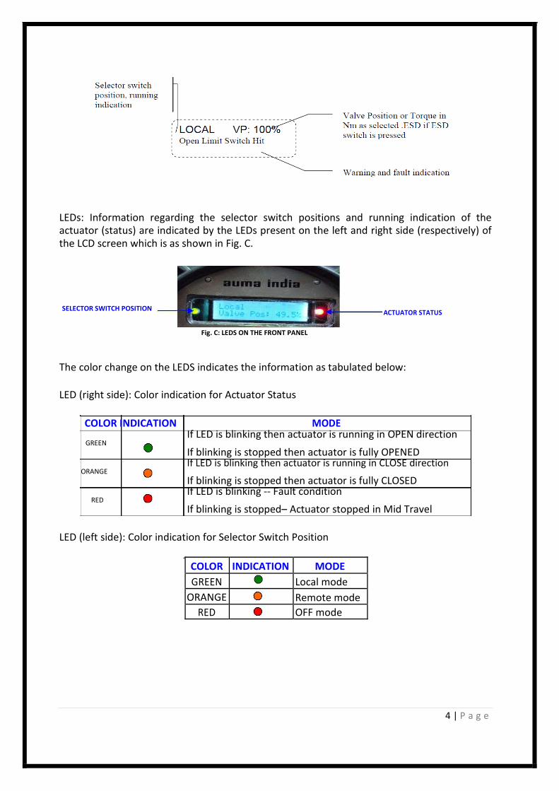
LEDs: Information regarding the selector switch positions and running indication of the actuator (status) are indicated by the LEDs present on the left and right side (respectively) of the LCD screen which is as shown in Fig. C. SELECTOR SWITCH POSITION
ACTUATOR STATUS
Fig. C: LEDS ON THE FRONT PANEL
The color change on the LEDS indicates the information as tabulated below: LED (right side): Color indication for Actuator Status
COLOR INDICATION MODE If LED is blinking then actuator is running in OPEN direction
GREEN If blinking is stopped then actuator is fully OPENED If LED is blinking then actuator is running in CLOSE direction
ORANGE If blinking is stopped then actuator is fully CLOSED If LED is blinking -- Fault condition
RED If blinking is stopped– Actuator stopped in Mid Travel
LED (left side): Color indication for Selector Switch Position
COLOR INDICATION MODE GREEN Local mode ORANGE Remote mode RED OFF mode

5 | P a g e
Enter Password
0 * * *
Use Open/Close key to move up/down
Stop key to enter move to next position
General Setting Press Stop Key
Close Open
Remote Setting Press Stop Key
Close Open
Change password Stop To enter
Close Open
Exit Program Mode Stop To enter
Close Open
Remote setting Stop To enter
Close Open
Relay setting Stop To enter
Close Open
Name Plate Menu Stop To enter
Close Open
Exit Program Mode Stop To enter
General setting
Stop To enter
PROGRAM MODE IN 3.XMP MODULE: To enter into Program mode follow the below steps, Step1: Keep the selector switch in OFF position
Step2: Press Open + Close keys (together) approximately 6 sec
Step3: Press the STOP key on the display of “Program Mode” as shown in the below Figure.
In this mode the two options available for the users are, EDIT & VIEW which is as shown below; Program Mode
Press Stop Key
Stop Key
View
open key Edit
Close key
VIEW (Open Key) EDIT (Close Key)

6 | P a g e
Fig. F: Program Mode Flow chart for 3.XMP (Version 2.0)
A. EDIT option of the Program mode: By entering the appropriate password (default password is 0000 for minor changes & 5555 for major changes), user can enter into the EDIT option. (The features relevant to Modbus communication are explained here);
1. General Settings: ESD option ESD options can be excited in following ways; 1. Hardwired ESD: Use the customer end terminals ESD+ & ESD- for the external push
button connection (planned usually outside the dyke area), for exciting the ESD over hard wired. This command has the highest priority compared to all other command including Modbus ESD
2. Soft ESD: To use the ESD command excitation over Modbus, ensure that the option ESD_MB is enabled. Soft ESD command can be excited/de-excited in 2 ways;
a. ESD excitation on individual actuator b. Broadcast ESD
3. Required option on ESD: There are 3 modes in which the actuator can be made to operate on excitation of ESD command (either hardwired or soft ESD). They are;
a. Open b. Close (it is the default option) c. Stay as it is
For enabling “soft/Modbus ESD”, select the ESD option in general setting, which is as shown below :

7 | P a g e

8 | P a g e
2. Remote Settings: This menu is used for setting of the Modbus parameters such as device ID, baud rate, parity etc.
Please note the following, before the setting of Modbus parameters; 1. Unique “Device ID” should be set for individual actuators/participants which will be
communicating with the DCS/AIMS on a single loop/line 2. Baud Rate (BPS), Parity of the individual actuators communicating over the same
loop/line should be same and should match with the settings of the supervisory device (which can be DCS/AIMS)
3. Repeater functionality will be set to yes “Y”, only for loop topology.
Note: Modbus settings of the actuators can be viewed on LCD, by keeping the selector switch in “REMOTE” & then pressing the “CLOSE” push button which is as shown below;
Parity
Device ID Repeater Function
Baud Rate
If the above displayed settings are not matching with the intended options for Modbus communication, then for changing the Modbus parameters, use the below flowchart.
The sub options available in this category are

9 | P a g e
Note: LCS priority- LCS stands for Local Control Station.
To use the 4 wire remote option for Open, Stop & Close along with the regular Modbus mode, this option needs to be enabled. By using the 24VDC (+ & -) with the customer end terminals RMO, RMS, RMC & RMN (of the individual actuators), these commands can be excited by using the external push button station assembly. LCS will operate only in inching mode LCS will have higher priority than Modbus commands

10 | P a g e
Option 2 – calibration mode
Following flowchart can be followed for the calibration:

11 | P a g e

12 | P a g e
1. Torque setting :

13 | P a g e
2. DAC output calibration :

14 | P a g e
3. 4 – 20 mA calibration:

15 | P a g e
4. Limit setting :

16 | P a g e
TOPOLOGY CONNECTION: The actuators can be connected to the DCS/AIMS on 2-wire (data line + & -) field bus mode, in the following ways;
Loop topology Line topology or Redundant Line topology
Let us consider the customer end connection of the wiring diagram, to understand the fieldbus interconnection details; Please note the below (w.r.t. the above WD) points for topology interconnection.
1. Data lines of channel A are A+ & A- which are made available at customer end terminals 1, 3 and 2, 4 respectively.
2. The signal ground/reference line for channel A communication is identified as “A Shield”, which should run along the channel (as per Modbus standard) and this is made available at customer end terminal 5.
3. Data lines of channel B are B+ & B- which are made available at customer end terminals 10, 12 and 11, 13 respectively.
4. The signal ground/reference line for channel B communication is identified as “B Shield”, which should run along the channel (as per Modbus standard) and this is made available at customer end terminal 14.
5. Terminations can be activated using the DIP switch available on the Interface Card NOTE:
Use the repeaters if the distance between the active adjacent participants exceeds1.2km In case of line/redundant line topology, use repeaters after 32 participants, with proper
terminations even at repeaters. Termination resistors are to be planned at each port of the DCS (AIMS has termination built
within)

17 | P a g e
Pictorial representation of topology (actuator interconnection) details:
Note: For Loop configuration, Terminations should be made ON for each channel.

18 | P a g e
REGISTER DETAILS FOR MODBUS COMMUNICATION:
The important register & function code details needed for command excitation and status reading are as below; COMMAND EXCITATION: Function Code 0x03, 0x06 & 0x10: The holding register details for read & write operations associated with these function codes are as below;
ADDRESS DATA
DESCRIPTION
VALUE RANGE
NOTE (MEANING)
(MIN-MAX)
BIT 8=1 OPEN
REMOTE 0x03E8
BIT 9=1 CLOSE
COMMAND BIT 12=1 STOP
BIT 10=1 SET POINT BIT
READ VALVE 0x03E9 0-1000
POSITION
SET VALVE 0x03EA 0-1000
POSITION
**REMOTE
COMMAND 0x0001 BIT 0=1 ESD
(ESD)
The byte sequence for *broadcast ESD (SOFT ESD) command in hexadecimal is:
Broadcast Function Start Start Register Register CRC CRC Address Code Address Address Value Value High Low High Low High Low
0xF1 0x06 0x00 0x01 0x00 0x01 0x0D 0x3A
Note:
**: Soft ESD at individual actuator is available with 3.XMP modules having 2nd
Series of controller in
CPU card, starting with the program version”VER2:2014-04-06” & the program version starting from
Version 26 onwards in case of 1st
series of 3.XMP CPU cards.

19 | P a g e
STATUS READING: Function Code 0x04: There are two registers present with the address 0x03E8 & 0x03E9 from which the status details can be got. The details of the data associated with each address are as tabulated below;
ADDRESS 0x3E8 0x3E9 0x3EA
DATA DETAILS
BIT DESCRIPTION
POSITION
0 LOCAL POSITION TSC
1 REMOTE POSITION TSO
2 RUNNING OPEN LSC
3 RUNNING CLOSE LSO Valve
4 STOPPED
LOCAL POSITION
Position
(0-1000)
5 OPENED POSITION REMOTE POSITION
6 CLOSED POSITION LOSS OF PHASE
7 TSO TH FAULT
8 TSC COMMON FAULT
9 TH FAULT PHASE REVERSE
10 TOLR RUNNING CLOSE x
11 JAMMED VALVE RUNNING OPEN x
12 PHASE SEQ. ERROR ESD-HARDWIRED x
13 SET POINT REACHED SET POINT REACHED x
14 FAULT CLOSED x
15 LCS ACTIVATED OPENED x
The byte sequence for Command & Status consists of following fields;
Function Address (2 Bytes)
Data Value CRC
Device ID (2 Bytes) (2 Bytes)
Code
(1 Byte) High Low High Low High Low
(1 Byte)
Byte Byte Byte Byte Byte
Byte
As a general practice function code 0x06 is used for command excitation & for status reading the function code 0x04 will be used: The other details needed for the modbus communications such as Function Code, address, Data to be written are listed below; Function Code Details (as implemented by auma):

20 | P a g e
DESCRIPTION VALUE 1. READ COIL STATUS 0x01 2. READ INPUT STATUS 0x02 3. READ HOLDING REGISTERS 0x03 4. READ INPUT REGISTERS 0x04 5. FORCE SINGLE COIL 0x05 6. FORCE MULTIPLE COIL 0x0F 7. PRESET SINGLE REGISTER 0x06 8. PRESET MULTIPLE REGISTERS 0x10 9. DIAGNOSTICS 0x08
a. LOOP BACK 0x00 b. CLEAR COUNTERS 0x0A c. RETURN BUS MESSAGE COUNT 0x0B d. RETURN BUS COMMUNICATION ERROR COUNT 0x0C e. RETURN BUS EXCEPTION ERROR COUNT 0x0D f. RETURN SLAVE MESSAGE COUNT 0x0E g. RETURN SLAVE NO RESPONSE COUNT 0x0F
Function Code 0x02: The register details associated with this function code (Read Input Status) are as below;
DESCRIPTION ADDRESS IN HEX OPEN POSITION 0x0000 CLOSE POSITION 0x0001 SET POINT REACHED 0x0002 RUNNING OPEN 0x0004 RUNNING CLOSE 0x0005 THERMAL FAULT 0x0008 REMOTE SW POSITION 0x000A LOCAL SW POSITION 0x000B LSO 0x000C LSC 0x000D TSO 0x000E TSC 0x000F

21 | P a g e
Note: The data values of this function code is to be indicated in binary (1/0) Function Code 0x01, 0x05 & 0x0F: The register details for read & write operations associated with these function codes (coil status) are as below;
DESCRIPTION ADDRESS IN HEX 1. REMOTE OPEN 0x0000 2. REMOTE CLOSE 0x0001 3. REMOTE SET POINT 0x0002 4. REMOTE SW POSITION 0x0020 5. OFF SW POSITION 0x0021 6. LOCAL SW POSITION 0x0022
Note: The data values of these function codes are to be indicated in binary (1/0)

22 | P a g e
General Guidelines for effective communication: Ensure the following:
1. No short between the DATA+ & DATA- lines on each channel
2. No interchange/reversing in connection of DATA+ & DATA- lines of each channel, when polling from
the external Master.
3. A common reference line/Signal Ground known as “A Shield” for Channel A or “B Shield” for
Channel B runs along the communication path
4. Signal Ground is not connected to Earth point and it is referenced (shorted with device) only at one
end
5. Minimum setting of Com receive byte value as 20 considering the 2 byte transfer on each poll; If the
communication poll needs more than 2 bytes accordingly the Com RX byte to be varied in the range
of 20 to 100
6. Repeater mode is kept “YES” only for loop topology

23 | P a g e
TROUBLE SHOOTING If the right hand side LED (red color) blinks (as shown in Fig. C) it indicates the FAULT. To identify the fault, check the status displayed on the LCD; Following are the typical displays of the FAULT condition and the trouble shooting methods to resolve those issues.
1. DISPLAY-24V supply fail:
TROUBLESHOOTING:
1.1. Check whether FRC cable is properly connected between CPU card and Power Supply card.
1.2. Measure the DC ǀoltage ďetǁeeŶ + aŶd - terŵiŶals iŶ Custoŵer TerŵiŶal Compartment
using a multimeter. Here we are suppose to get 24VDC, If no voltage is coming then measure
the resistance between those terminals using a multimeter by disconnecting the MAINS, If
there is a dead short, then replace Power Supply Card.
2. DISPLAY- “iŶgle Phase
TROUBLESHOOTING:
2.1. Check whether the fuses in R (FS1) &/or B (FS2) phases are blown.
2.2. Ensure that the MAINS 3phase input supply voltage and frequency of operation is matching
the ratings mentioned on the name plate.
2.3. Check whether FRC cable is properly connected between CPU card and Power Supply card.
2.4. Check J2 of Power Supply card is connected properly.
2.5. If still Single Phase indication is present then measure the AC Voltage in J2 Connector (Male)
using multimeter between two white wires and two black wires; this voltage is suppose to be
16VAC. If this voltage is very less than 16VAC then problem could be with transformer;
replace the transformer and check.
3. DISPLAY- TH “ǁitch Trip
TROUBLESHOOTING:
3.1. Check the motor thermo switch continuity; if continuity is not there then we have to replace the
motor.
3.2. With motor thermo switch continuity check the continuity between wires with ferrule TH
and F1 of the J6 on CPU card; if there is no continuity then check the wiring error.
3.3. With the above two corrections, if the same error message display continues, then replace the
CPU card.

24 | P a g e
4. DISPLAY- TOLR Trip
TROUBLESHOOTING:
4.1. Disconnect the supply to actuator and check whether TOLR is tripped; if yes then reset TOLR
using reset switch as shown in fig below.
Fig. D: TOLR
4.2. Check the continuity between the input and output terminals of TOLR, if there is no continuity
then TOLR are faulty, replace the TOLR.
4.3. If TOLR is not tripped and the error message continues then check the TOLR selection NO/NC
under program mode; verify wires with ferrule 95 and 96 coming from J6 on Power Supply card
are connected properly to TOL‘s respeĐtiǀe ĐoŶtaĐts depending on NO (Terminals-97, 98) or NC
(Terminals-95, 96). Check continuity for these wires from TOLR terminals to J6 connector of
Power Supply card.
4.4. If continuity is present but still TOLR trip is showing then check FRC Cable is connected properly
between Power supply card and CPU Card.
4.5. If still problem continues then replace CPU and POWER cards.
5. DISPLAY- “pace Heater fault
TROUBLESHOOTING:
5.1. Check whether Fuse -F4 is blown; if yes replace with good fuse of 1A, 250V rating
5.2. With the help of multimeter measure the Space heater voltage (ACV) voltage between brown
and brown wires of J3 on Power Supply card. (The value will be 220VAC / 110VAC /24VAC
depending on the customer requirement). If the requisite voltage is not measured then check
the Molex connector between fuse plate and transformer.
5.3. If the requisite voltage is measured; but display continue to show the same error message
then replace the power supply card. But if the requisite voltage is not measured then the
fault could be with transformer, replace with new transformer and check again.
RESET Switch

25 | P a g e
6. DISPLAY- CoŶtrol supply fail
TROUBLESHOOTING:
6.1. Check whether Fuse-F3 is blown; if yes replace with good fuse of 1A, 250V rating
6.2. With the help of multimeter measure the control supply voltage (AC voltage between Orange
and Black wires of J3 on Power Supply card), which is to be 220VAC/110VAC as per the
customer requirement. If voltage is not coming then check the Molex connector between
fuse plate and transformer.
6.3. If the requisite voltage is measured; but display continue to show the same error message
then replace the power supply card. But if the requisite voltage is not measured then the
fault could be with transformer, replace with new transformer and check again.
7. DISPLAY- Jaŵŵed Valǀe
TROUBLESHOOTING:
7.1. The Jammed valve condition is to be released manually
8. DISPLAY- TW ERROR
TROUBLESHOOTING:
8.1. Whenever there is a replacement of new transformer,
there is a possibility of occurrence of this error. To
troubleshoot this interchange the 2 wires (white pairs or
the black pairs) in the connector J2 (i.e. 1&2 or 3&4 of the
connector J2) of the PS Card
9. Motor running in wrong direction: Whenever there is a replacement of Motor then there is a
possibility of occurrence of this error i.e. the actuator will run in wrong direction for the respective
command inputs (actuator runs in open direction for close command and vice versa). To
troubleshoot this
9.1. Interchange any 2 wires of the motor when the Motor is replaced
10. In case if Remote-local mode selection option from REMOTE is not happening (optional feature);
check for the wiring at the customer end according to the WD.
11. IŶ Đase of aĐtuator ruŶŶiŶg iŶadǀerteŶtly ;ǁith E“DY ŵessage oŶ LCDͿ either iŶ OPEN or CLOSE
direction depending on the selection done, check if ESD is activated (wiring mistake) using the WD

26 | P a g e
provided.
12. In case the actuator is not taking command in any particular direction check if INHIBIT feature is
enabled (wiring mistake) using the WD provided.
13. In case the motor is not responding to the OPEN & CLOSE command and OPENING/CLOSING is
indicated on LCD: Check if J4 of Power Supply card is plugged properly. Check the requisite voltages
(110/230V) at the contactor terminals (K, K1 & K, K2
–refer Fig. E).
13.1. If the voltages are proper it could be the failure of the contactor; replace the contactor.
13.2. If the voltages are not proper, it means relay failure on the PS card; replace the PS card.
14. Actuator showing Single Phase error / TW error under running condition: This problem is due to
Transformer module; hence it is to be replaced.
15. Mode selected in Local option is not displaying on the LCD screen: This problem arises if
‘eŵote “el. “ǁitĐh optioŶ is eŶaďled. To disaďle this optioŶ, eŶter iŶto the Prograŵ Mode –
General Settings or use the Remote-MODBU“ ĐoŵŵaŶd ;iŶput ϬY to the register 309 in the single
register modbus function code).
16. “igŶal Fault iŶdiĐatioŶ iŶ reŵote-2Wire mode: Under Remote-regulating duty mode we have to
give 4-20mA DC Current from external DC source to the respective terminals
;as per WDͿ Ŷaŵed ǁith ferrule II+ aŶd II-; CheĐk the ĐoŶŶeĐtiǀity of Jϱ ĐoŶŶeĐtor at the Interface
Board and also verify the wiring with respect to WD and ensure that the 4- 20mA input is coming
from DCS.
17. LCD Display is blank with back light ON: Check whether all respective connectors are plugged
properly and ensure that the shorting link is connected properly (as shown) on J2 and J3 of CPU card
K K
K1 K2
Fig. O: CONTACTOR

27 | P a g e
17
Spare Parts:
PS CARD INTERFACE CARD

28 | P a g e
EPAC nameplate:
Identify the location of the epac name plate on the actuator which is as shown in the Fig. L
EPAC name plate
Fig. J: Actuator with EPAC
The following relevant details are available on the EPAC name plate to ensure our support after supply
Commission no. of the actuator EPAC version
Wiring diagram number
Ordering code for EPAC
Fig. K: EPAC name plate
Please furnish the above details of the name plate while ordering spare parts/after sales support.
Regd. Office & Works: Noida Branch: Pune Branch: Kolkata Branch: 38A & 39-B, II Phase, 1310,Tower ‘A’, 712,713, Bldg.No. 1, Ph: 09883029170 Peenya Industrial Area Corenthum Complex “Siddharth towers”, Email: [email protected] Bangalore – 560058 Sector -62, Noida -201309 Kothrud, Pune - 411038 Ph: 080-30412222/28394656 Ph: 0120-3060522 – 26 Ph: 020-25410465 Chennai Branch: Fax: 080-28392809 Fax: 0120-3060523 Fax: 020-25443186 Ph: 09884119795 Email: [email protected] Email: [email protected] Email: [email protected] Email: [email protected]