operation manual - flexcodocumentlibrary.flexco.com/x5382_enus_5382_ehmanual...6. step on foot pedal...
TRANSCRIPT

Electric-Hydraulic Lacer Operation Manual

Your Lacer Identification
Model No.
Serial No.
Date Purchased
Please use correct model number and serial number when corresponding with your Flexco Distributor or with Flexco Customer Service. Proper identification will help us to quickly and efficiently answer your question or service you with repair parts.
Thank you, Flexco
Congratulations on your purchase of a Clipper® Electric Hydraulic Lacer. This lacer is a vital part of the best Wire Hook System available today.
The Clipper Electric-Hydraulic Lacer is the fast, reliable method of handling all of your production belt lacing needs. Your lacer can be plugged into any compatible electrical power source and the casters allow for complete mobility. Belts up to the width of the lacer can be laced in a single operation and the continuous lacing feature means you can lace any width belt. With the use of optional hook retainers, this lacer can install any size Clipper hook.
This operation manual has been compiled for your use. PLEASE READ THE MANUAL CAREFULLY BEFORE ATTEMPTING TO USE YOUR LACER EVEN IF YOU ARE FAMILIAR WITH THE MACHINE. The manual provides important information regarding the lacer and proper lacing procedures for your safety.
If you have any questions about your lacer, please contact your Flexco Distributor or our Customer Service Department. Be sure to use the identification information listed below.
INTRODUCTION

TABLE OF CONTENTS Lacer Identification Information .................... Inside Front CoverLacer Picture ........................................................................... 2 Preparing Your Lacer For Operation ......................................... 2For Your Safety ......................................................................... 3Proper Lacing Procedures ........................................................ 4Lacing Accessories Kit .............................................................. 4Preparing the Belt for Lacing .................................................... 4Loading the Hook Retainer ....................................................... 5Lacer Operation ........................................................................ 5Continuous Lacing Wide Belts .................................................. 6Using a Filler Strip .................................................................... 6Changing Hook Retainers ........................................................ 6Lacing Tips and Advice ............................................................. 7Optional Clipper Accessories .................................................... 7Readjusting the Lacer Jaws ..................................................... 8Maintenance ............................................................................. 8Troubleshooting ........................................................................ 9Parts List..................................................................................10Lacer Stand and Hydraulic Components ................................. 12General Specifications....................................Inside Back Cover
1

Preparing Your Lacer For Operation
1. Remove package containing hook retainer(s) and lacer pin(s) and set them aside for the moment.2. Set floor lock to stabilize lacer while you work on it.3. Visually check fluid level. Fluid should be 1-1/2" (38 mm) below the top of the hole. Install breather cap.
Screw in the breather cap hand tight. IMPORTANT: Breather cap must be installed or pressure buildup may result in damage to lacer. Note: You may want to save the shipping plug for use again in the event the lacer is transported to another location.
4. Remove tag from power cord and double-check that the lacer’s voltage is compatible with your power source. 5. Plug in power cord and turn On/Off switch to the ‘On’ position. As an energy-saving feature, the motor does not
run until the foot pedal is depressed.
2
Jaws
Frame Arms
Power Cord
On/Off Switch
Floor Lock
Foot Pedal
Adjusting Lever
G0326STAND
ASSEMBLY
03091
G0272G0311
03802
G0249G140403303
G0248G140403303
034690330303287
G0247
G0312
G0218
G4814
G4382
03796
03798
G4044G4045G123103287
Floor Lock
Breather Cap
Pressure Gauge

6. Step on foot pedal and cycle the lacer to be sure it is working properly. Lacer jaws will open at any point in the cycle if your foot is lifted from the pedal. Note: A slight squealing noise at mid-cycle is normal. This is caused by the hydraulic fluid going through the relief valve.
7. Install the Hook Retainer. Turn lacer off and turn adjusting lever counterclockwise to completely open the jaws. Standing in front of the lacer, insert hook retainer with continuous lacing slots on your left. Slots in bottom of retainer must fit onto plungers in the lacer. Retainer should float up and down on plungers. Hold retainer and turn adjusting lever clockwise closed until retainer fits into the slots in the jaws (Fig. A & B).
8. Use of Lacer Pin: Every hook retainer comes with a lacer pin for securing hooks in the retainer. Insert pin into the retainer. Note: To insure a proper lace, use the Clipper lacer pin only.
Your lacer is now ready for lacing. Please refer to recommended lacing procedures and safety reminders on the following pages.
Hold down Retainer slightly so it fits into slots in jaws (Fig. A), not above slots (Fig. B).
For Your Safety:All Electric-Hydraulic Lacers have the following safety features:• Top Guards - To prevent fingers and other materials from getting near moving parts.• Foot Pedal Control - Releasing pressure on foot pedal at any point in the cycle will immediately open
the lacer jaws.• Foot Pedal Guard - Foot pedal is enclosed to prevent accidentally engaging it.• Warning Stickers - Located on top guards to continually remind the operator of safety precautions.
To Ensure Operator Safety, Follow These Simple Rules:1. Always engage the floor lock when using the lacer.2. Plug the lacer into power sources with proper voltage.3. Operate lacer directly from electrical wall receptacle. If extension cord must be used, use #14 AWG for
distances up to 20 feet and #12 AWG for distances greater than 20 feet.4. Never operate the lacer with the guards removed.5. When cycling the lacer, keep fingers, clothing and jewelry well away from closing jaws.6. Never place tools or other foreign objects on the lacer that could fall between the jaws during operation.7. Unplug the lacer during maintenance or repairs and when not in use.
8. Look at hydraulic lines for cracks and wear, so fluid does not leak.
3
Fig. A Fig. B
Foot Pedal

Proper Lacing ProceduresLacing Accessories KitIncluded with your lacer is a Lacing Accessories Kit. This Kit will be referred to in the following lacing steps. We recommend their use to make lacing installation as easy and fast as possible.1. Hook Gauge - To select the proper size hook for your belt thickness and
minimum pulley diameter.2. Rough Top Belt Skiver - Removes rough top impression covers from belt for
best lacing results.3. Carding Paper Remover - For quick removal of carding paper from
hook points. Prevents damage to hook retainer caused by using knives, screwdrivers and other sharp objects to remove carding paper.
4. Scissors - To cut hook cards to proper size.
Hook Gauge
Skiver Scissors
Preparing the Belt for LacingPreparation of your belt is as important as the actual lacing of the fasteners.1. Square belt ends. The Clipper® 845LD Belt Cutter is a portable cutter that can provide a quick, safe, accurate cut.
See Figure A. For belts with worn edges, it is necessary to find the center line of the belt. To do this, take an even measurement wider than the belt width; (Ex. 48" for a 42" belt) measure diagonally and mark the center point (Ex. 24"). See Figure B. Repeat this step at least four more times, moving the tape measure one foot along the belt for each position. See Figure C. On a typical belt with worn edges, the center points marked will not be in a straight line. Take a straight edge and draw a line as close to connecting the center points as possible. This will determine an average center line. Then draw a line perpendicular to the average center line. See Figure C. The belt end will be square when cut along this line.Use the Clipper® 845LD Belt Cutter to cut the belt.
2. Determine hook size needed. Use your Clipper Hook Gauge for general fastener size recommendations for belt thickness and minimum pulley diameter. Select the proper size hook for the application.
3. Determine the number of cards needed for the splice by laying cards of hooks across the belt end. Note: It is recommended that 1/4" (6-1/2 mm) on each belt edge be left unlaced. See Lacing Tips and Advice on page 7.
Fig. BFig. A Fig. C
4
Carding Paper Remover

Loading The Hook Retainer1. Turn adjusting lever counterclockwise until jaws open wide enough for hooks to fit
in easily.2. Remove lacer pin.3. Clipper wire hooks come in two different carding styles and also in a Unibar®
configuration. If using hooks as shown in Figure A, insert card(s) of hooks with carding paper reading upside down (for easy removal of carding paper). See Figure D. It does not matter which way the carded hooks as shown in Figure B or Unibar hooks are inserted into the hook retainer. Reinsert lacer pin to lock hooks in place. Hooks should not be in the two continuous lacing slots.
4. Close adjusting lever until hook legs are held firmly between jaws. Use caution to ensure fingers, clothing and/or jewelry are free from jaws while in operation. Note: For #1, #25, and #36 Series hooks, bringing jaws up snug to hook legs may cause over-compression on some belt thicknesses. For these hooks, size belt for proper clinch before loading hooks: Place belt between lacer jaws, cycle lacer and use adjusting lever to bring jaws up snug against belt. Tighten 1/2 to 3/4 turn. This will be your final lace position.
5. If using hooks as shown in Figure A, remove paper at this time. If using Unibar hooks, remove safety strip at this time. It is recommended to remove the carding paper from the back side of the hooks first by using the carding paper remover as shown in Figure E. Once the entire back side has been removed, uncurl the paper, grasp the paper and push it up and away from the hooks (Figure F). If using hooks shown in Figure B, the paper will remain on until after the lacing process is complete and then is removed.
Fig. D Fig. E Fig. F
1. Position belt squarely over lacer. An overhead hanger or table abutting the lacer will be helpful. Leaving plenty of slack in the belt will make it easier to hold belt down on hook retainer.
2. Hold belt down flush onto hook retainer (belt end will be perpendicular to hook retainer).
3. When belt is in the proper position, depress the foot pedal. Use caution to ensure fingers, clothing and/or jewelry are free from jaws while in operation. Hold pedal down until the jaws close and stop. Let up on pedal and lacer jaws will open.
4. Examine hook clinch. Hooks are properly clinched when: 1) Approximately 1/2 the diameter of the hook leg is embedded into the belt 2) .010" to .015" (.3 - .4 mm) of the hook points are visible (On rubber belting, hook points will recede into belt cover when jaw pressure is released).
5. If further clinch is required, turn adjusting lever clockwise 1/4 turn and cycle lacer again. Continue this process until hooks are properly clinched.
6. Remove lacer pin. Pull laced belt straight up from hook retainer with a gentle rocking motion.
Lacer Operation
Fig. A
Fig. B
Fig. C
5

Your lacer comes standard with a regular hook retainer for lacing hook sizes #2-#7 and U2-U7. Hook retainers are available for lacing #25, #1/UX1 as well as #36/UCM36 and #30 Series hooks.To change retainers: 1. Turn power off. 2. Turn adjusting lever (counterclockwise) to open lacer jaws. 3. Lift out hook retainer. 4. Install new hook retainer making sure the continuous lacing slots are to the left. The retainer should float up
and down on the plungers.5. Hold retainer down slightly and turn adjusting lever clockwise three turns. The retainer will fit into the slots in
the jaws. 6. Store unused retainers and lacer pins in a safe place so they will not be damaged.
Using A Filler Strip
Continuous Lacing Wide BeltsThe hook retainer has been designed with two continuous lacing slots for precision alignment of each hook on a wide belt splice. From the operator’s position, the continuous lacing slots should be on the left side. It is necessary to always lace a wide belt from left to right, so the last two laced hooks can be placed in the continuous lacing slots.
1. Determine the number of cards needed for the entire splice prior to lacing. Then, any section less than the capacity of the lacer can, and should be laced first. For example, if you are using a 25" lacer to lace a 30" belt, lace the short section first. By using this method, there will always be belting between the full width of jaws and pressure exerted will be equalized. This will help keep lacer jaws in proper adjustment.
2. After the first lacing operation is complete, note the finished position of the adjusting lever (this is easy to remember by using clock positions as reference points). IT IS VERY IMPORTANT TO COMPLETE EACH LACED SECTION WITH THE ADJUSTING LEVER IN THE SAME POSITION. This will ensure that the hooks are all clinched exactly the same, giving maximum strength and performance.
3. Now, prepare to lace the next section of the belt. Load the hook retainer with cards of hooks. It may be necessary to turn the adjusting lever counterclockwise one turn to open the jaws for easy insertion of the new cards. Return the adjusting lever to the established finishing position. Remove carding paper.
4. Reposition lacer or belt to the next section to be laced.5. Insert last two hooks of the laced section into the two continuous lacing slots.6. Hold belt firmly on hook retainer. Continue with standard lacing procedures.
Caution: If the belt is not held down firmly onto the hook retainer or if it is held at an extreme angle, a step in the lacing may occur between laced sections, and the splice will not perform to maximum capabilities.
7. Repeat this procedure across entire width of belt.
6
Changing Hook Retainers
When lacing belts less than 3/4 of the capacity of the lacer it is recommended that a filler strip be used to equalize the pressure exerted along the length of the jaws. This can easily be done by using a scrap piece of belting the same thickness as the belt being laced. The filler strip will ensure that no undue stress will be put on the lacer that may cause damage to its parts. Failure to follow this procedure can result in broken castings, leaving the lacer inoperable.
Incorrect Angle
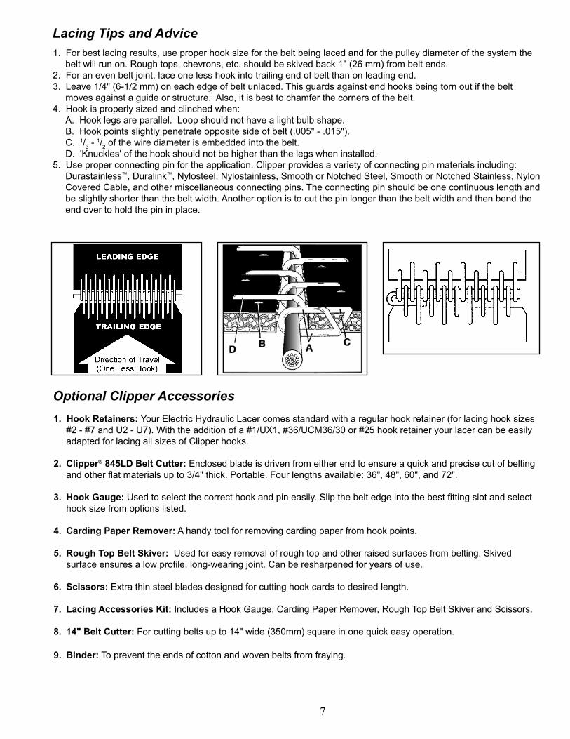
Lacing Tips and Advice 1. For best lacing results, use proper hook size for the belt being laced and for the pulley diameter of the system the
belt will run on. Rough tops, chevrons, etc. should be skived back 1" (26 mm) from belt ends.2. For an even belt joint, lace one less hook into trailing end of belt than on leading end.3. Leave 1/4" (6-1/2 mm) on each edge of belt unlaced. This guards against end hooks being torn out if the belt
moves against a guide or structure. Also, it is best to chamfer the corners of the belt.4. Hook is properly sized and clinched when: A. Hook legs are parallel. Loop should not have a light bulb shape. B. Hook points slightly penetrate opposite side of belt (.005" - .015"). C. 1/3 -
1/2 of the wire diameter is embedded into the belt. D. 'Knuckles' of the hook should not be higher than the legs when installed.5. Use proper connecting pin for the application. Clipper provides a variety of connecting pin materials including:
Durastainless™, Duralink™, Nylosteel, Nylostainless, Smooth or Notched Steel, Smooth or Notched Stainless, Nylon Covered Cable, and other miscellaneous connecting pins. The connecting pin should be one continuous length and be slightly shorter than the belt width. Another option is to cut the pin longer than the belt width and then bend the end over to hold the pin in place.
1. Hook Retainers: Your Electric Hydraulic Lacer comes standard with a regular hook retainer (for lacing hook sizes #2 - #7 and U2 - U7). With the addition of a #1/UX1, #36/UCM36/30 or #25 hook retainer your lacer can be easily adapted for lacing all sizes of Clipper hooks.
2. Clipper® 845LD Belt Cutter: Enclosed blade is driven from either end to ensure a quick and precise cut of belting and other flat materials up to 3/4" thick. Portable. Four lengths available: 36", 48", 60", and 72".
3. Hook Gauge: Used to select the correct hook and pin easily. Slip the belt edge into the best fitting slot and select hook size from options listed.
4. Carding Paper Remover: A handy tool for removing carding paper from hook points.
5. Rough Top Belt Skiver: Used for easy removal of rough top and other raised surfaces from belting. Skived surface ensures a low profile, long-wearing joint. Can be resharpened for years of use.
6. Scissors: Extra thin steel blades designed for cutting hook cards to desired length.
7. Lacing Accessories Kit: Includes a Hook Gauge, Carding Paper Remover, Rough Top Belt Skiver and Scissors.
8. 14" Belt Cutter: For cutting belts up to 14" wide (350mm) square in one quick easy operation.
9. Binder: To prevent the ends of cotton and woven belts from fraying.
Optional Clipper Accessories
7
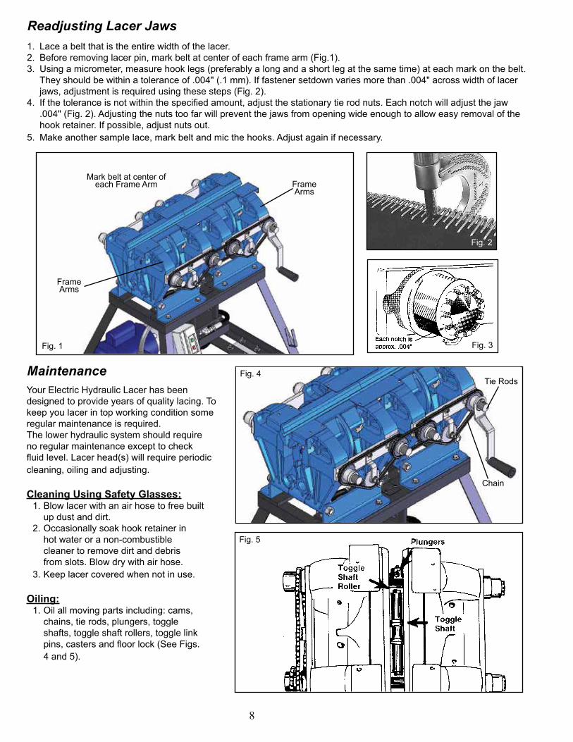
Readjusting Lacer Jaws1. Lace a belt that is the entire width of the lacer. 2. Before removing lacer pin, mark belt at center of each frame arm (Fig.1).3. Using a micrometer, measure hook legs (preferably a long and a short leg at the same time) at each mark on the belt.
They should be within a tolerance of .004" (.1 mm). If fastener setdown varies more than .004" across width of lacer jaws, adjustment is required using these steps (Fig. 2).
4. If the tolerance is not within the specified amount, adjust the stationary tie rod nuts. Each notch will adjust the jaw .004" (Fig. 2). Adjusting the nuts too far will prevent the jaws from opening wide enough to allow easy removal of the hook retainer. If possible, adjust nuts out.
5. Make another sample lace, mark belt and mic the hooks. Adjust again if necessary.
MaintenanceYour Electric Hydraulic Lacer has been designed to provide years of quality lacing. To keep you lacer in top working condition some regular maintenance is required. The lower hydraulic system should require no regular maintenance except to check fluid level. Lacer head(s) will require periodic cleaning, oiling and adjusting.
Cleaning Using Safety Glasses: 1. Blow lacer with an air hose to free built up dust and dirt. 2. Occasionally soak hook retainer in hot water or a non-combustible cleaner to remove dirt and debris from slots. Blow dry with air hose. 3. Keep lacer covered when not in use.
Oiling: 1. Oil all moving parts including: cams, chains, tie rods, plungers, toggle shafts, toggle shaft rollers, toggle link pins, casters and floor lock (See Figs. 4 and 5).
8
Frame Arms
Frame Arms
Mark belt at center of each Frame Arm
Fig. 1 Fig. 3
Fig. 4
Fig. 5
Fig. 2
Tie Rods
Chain
Troubleshooting:
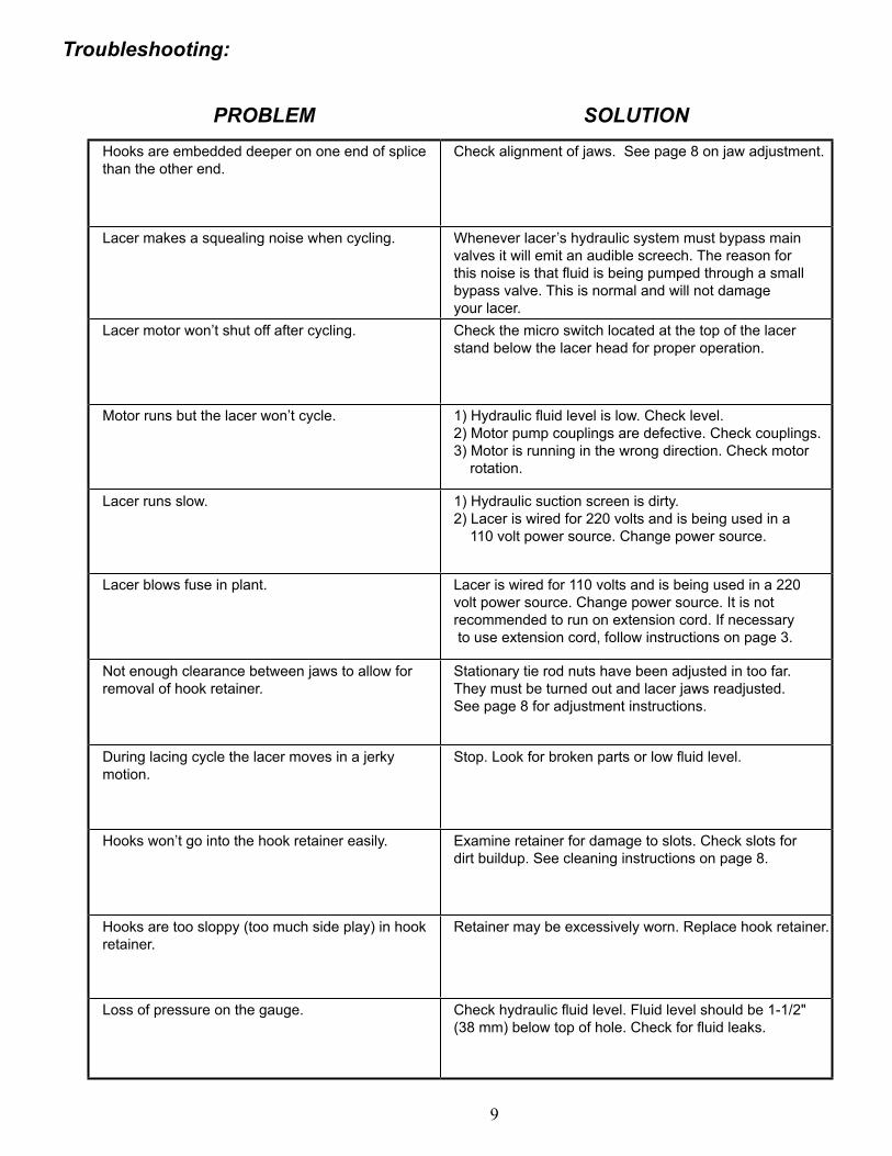
PROBLEM SOLUTIONHooks are embedded deeper on one end of splice than the other end.
Check alignment of jaws. See page 8 on jaw adjustment.
Lacer makes a squealing noise when cycling. Whenever lacer’s hydraulic system must bypass main valves it will emit an audible screech. The reason for this noise is that fluid is being pumped through a small bypass valve. This is normal and will not damage your lacer.
Lacer motor won’t shut off after cycling. Check the micro switch located at the top of the lacer stand below the lacer head for proper operation.
Motor runs but the lacer won’t cycle. 1) Hydraulic fluid level is low. Check level. 2) Motor pump couplings are defective. Check couplings.3) Motor is running in the wrong direction. Check motor rotation.
Lacer runs slow. 1) Hydraulic suction screen is dirty. 2) Lacer is wired for 220 volts and is being used in a 110 volt power source. Change power source.
Lacer blows fuse in plant. Lacer is wired for 110 volts and is being used in a 220 volt power source. Change power source. It is not recommended to run on extension cord. If necessary to use extension cord, follow instructions on page 3.
Not enough clearance between jaws to allow for removal of hook retainer.
Stationary tie rod nuts have been adjusted in too far. They must be turned out and lacer jaws readjusted. See page 8 for adjustment instructions.
During lacing cycle the lacer moves in a jerky motion.
Stop. Look for broken parts or low fluid level.
Hooks won’t go into the hook retainer easily. Examine retainer for damage to slots. Check slots for dirt buildup. See cleaning instructions on page 8.
Hooks are too sloppy (too much side play) in hook retainer.
Retainer may be excessively worn. Replace hook retainer.
Loss of pressure on the gauge. Check hydraulic fluid level. Fluid level should be 1-1/2" (38 mm) below top of hole. Check for fluid leaks.
9
10
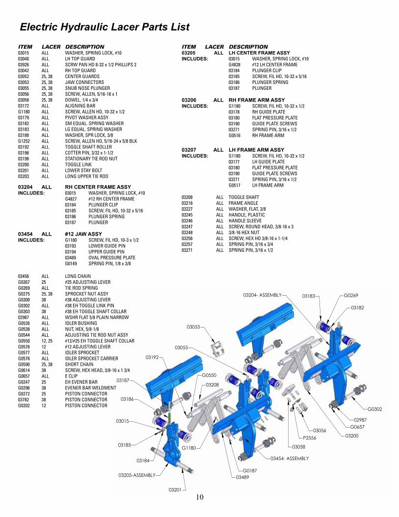
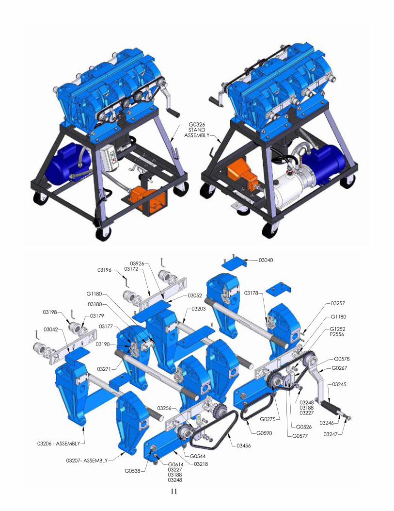
Electric Hydraulic Lacer Parts List
03205-ASSEMBLY
G1180
03489G0187
03185
03184
03015
03186
03187
03454- ASSEMBLY
03192
G0550
03208
03200
03183
03182
G026903204- ASSEMBLY
G0302
02987G0657
03201
03053
03056P2556
03058
03055
ITEM LACER DESCRIPTION03015 ALL WASHER, SPRING LOCK, #1003040 ALL LH TOP GUARD03926 ALL SCRW PAN HD 8-32 x 1/2 PHILLIPS 203042 ALL RH TOP GUARD03052 25, 38 CENTER GUARDS03053 25, 38 JAW CONNECTORS03055 25, 38 SNUB NOSE PLUNGER03056 25, 38 SCREW, ALLEN, 5/16-18 x 103058 25, 38 DOWEL, 1/4 x 3/403172 ALL ALIGNING BARG1180 ALL SCREW, ALLEN HD, 10-32 x 1/203179 ALL PIVOT WASHER ASSY03182 ALL SM EQUAL. SPRING WASHER03183 ALL LG EQUAL. SPRING WASHER03188 ALL WASHER, SPR LOCK, 3/8G1252 ALL SCREW, ALLEN HD, 5/16-24 x 5/8 BLK03192 ALL TOGGLE SHAFT ROLLER03196 ALL COTTER PIN, 3/32 x 1-1/203198 ALL STATIONARY TIE ROD NUT03200 ALL TOGGLE LINK03201 ALL LOWER STAY BOLT03203 ALL LONG UPPER TIE ROD
ITEM LACER DESCRIPTION03205 ALL LH CENTER FRAME ASSYINCLUDES: 03015 WASHER, SPRING LOCK, #10 G4828 #12 LH CENTER FRAME 03184 PLUNGER CLIP 03185 SCREW, FIL HD, 10-32 x 5/16 03186 PLUNGER SPRING 03187 PLUNGER
03454 ALL #12 JAW ASSYINCLUDES: G1180 SCREW, FIL HD, 10-3 x 1/2 03193 LOWER GUIDE PIN 03194 UPPER GUIDE PIN 03489 OVAL PRESSURE PLATE G0149 SPRING PIN, 1/8 x 3/8
03204 ALL RH CENTER FRAME ASSYINCLUDES: 03015 WASHER, SPRING LOCK, #10 G4827 #12 RH CENTER FRAME 03184 PLUNGER CLIP 03185 SCREW, FIL HD, 10-32 x 5/16 03186 PLUNGER SPRING 03187 PLUNGER
03456 ALL LONG CHAING0267 25 #25 ADJUSTING LEVERG0269 ALL TIE ROD SPRINGG0275 25, 38 SPROCKET NUT ASSYG0300 38 #38 ADJUSTING LEVERG0302 ALL #38 EH TOGGLE LINK PING0303 38 #38 EH TOGGLE SHAFT COLLAR02987 ALL WSHR FLAT 5/8 PLAIN NARROWG0526 ALL IDLER BUSHINGG0538 ALL NUT, HEX, 5/8-1/8G0544 ALL ADJUSTING TIE ROD NUT ASSYG0550 12, 25 #12/#25 EH TOGGLE SHAFT COLLARG0576 12 #12 ADJUSTING LEVERG0577 ALL IDLER SPROCKETG0578 ALL IDLER SPROCKET CARRIERG0590 25, 38 SHORT CHAING0614 38 SCREW, HEX HEAD, 3/8-16 x 1 3/4G0657 ALL E CLIPG0247 25 EH EVENER BARG0296 38 EVENER BAR WELDMENTG0272 25 PISTON CONNECTOR03782 38 PISTON CONNECTORG0202 12 PISTON CONNECTOR
03208 ALL TOGGLE SHAFT03218 ALL FRAME ANGLE03227 ALL WASHER, FLAT, 3/803245 ALL HANDLE, PLASTIC03246 ALL HANDLE SLEEVE03247 ALL SCREW, ROUND HEAD, 3/8-16 x 303248 ALL 3/8-16 HEX NUT03256 ALL SCREW, HEX HD 3/8-16 x 1-1/403257 ALL SPRING PIN, 3/16 x 3/403271 ALL SPRING PIN, 3/16 x 1/2
03207 ALL LH FRAME ARM ASSYINCLUDES: G1180 SCREW, FIL HD, 10-32 x 1/2 03177 LH GUIDE PLATE 03180 FLAT PRESSURE PLATE 03190 GUIDE PLATE SCREWS 03271 SPRING PIN, 3/16 x 1/2 G0517 LH FRAME ARM
03206 ALL RH FRAME ARM ASSYINCLUDES: G1180 SCREW, FIL HD, 10-32 x 1/2 03178 RH GUIDE PLATE 03180 FLAT PRESSURE PLATE 03190 GUIDE PLATE SCREWS 03271 SPRING PIN, 3/16 x 1/2 G0516 RH FRAME ARM
11
G0326STAND
ASSEMBLY
G0275
G05440321803207- ASSEMBLY
03206 - ASSEMBLY
03042
0319803179
03177
03190
03271
03180
G1180 03052
0392603172
03203
G0267
03245
03246
03247
G1180
03257
G1252P2556
032480318803227
G0526
G0577
G0578
G0538G0614032270318803248
03040
03178
03256
03196
03456
G0590

12
Lacer Stand And Hydraulic Components
G0250
G4457
03015
G4226
G0243
03783
03256
G0270G1180
032270324803188
02950G0252
0379503784
G0274
G0216G021503045
03287
G0217
G1180G0204
03015
G3765036890346903303
G1405
03091
G0272G0311
03802
G0249G140403303
G0248G140403303
034690330303287
G0247
G0312
G0218
G4814
G4382
03796
03798
G4044G4045G123103287
03783 ALL MOTOR TANK & PUMP ASSY 03045 ALL MICROSWITCH03046 ALL SWITCH03048 ALL PRESSURE GAUGE 03784 ALL FOOT SWITCHG0208 12 #12 HYDRAULIC CYLINDER G0243 25 #25 HYDRAULIC CYLINDER G0247 25 #25 EVENER BAR G0248 ALL SWIVEL CASTERG0249 ALL RIGID CASTER G0250 ALL FLOOR LOCKG0274 25 #25 EH CYLINDER SPACER G0295 38 #38 HYDRAULIC CYLINDER G0297 38 BOLT, HEX HD, 1/2-13 x 9-1/2 G0298 38 #38 EH CYLINDER SPACER

13
Lacer Pins (Lacer pins are supplied with each Hook Retainer)
#1/#36 ACUSTEEL HOOK RETAINER
03169
03162
03163
REG. ACUSTEEL HOOK RETAINER
03222
03054
03156
HOOK RETAINERS FOR HOOK SIZES:
Parts List - Hook Retainers
#25 (#25 ACUSTEEL)
03822
03823
03824
#36, UCM36, #30 (#36 ACUSTEEL)
03170
03154
03155
#1, UX-1 (#1 ACUSTEEL)
03168
03143
03150
#2-#7, U2-U7 (REG. ACUSTEEL)
03211
03051
03148
LACER MODEL NUMBER
03037
03038
03039
LACER WIDTH
12"
25"
38"
#25 ACUSTEEL HOOK RETAINER
03147
03146
03151
LACER WIDTH
12"
25"
38"
LACER MODEL NUMBER
03037
03038
03039
General SpecificationsHoses 3/8" (10 mm) ID, 2600 PSI (18MPa) working pressure, 8000 PSI (53MPa) bursting pressure.
Cylinder 2500 PSI (16 MPa) working pressure Stroke - 3-5/8" Bore - 12" Lacer - 2-1/2, 25" Lacer - 3-/2, 38" Lacer - 4-1/2
Relief Valve Settings Pump - 850-950 PSI (5.8-6.5 MPa) Motor - Split Single Phase, 110/ 220 VAC 60 cycle. 3450 RPM, direct coupled.
Hydraulic Power Supply Positive displacement gear pump unit with built-in relief valve and fluid reservoir.
Capacity Pump - 3.28 GPM (12 LPM) 1200 PSI (8 MPa) maximum pressure 3400 RPM Reservoir - 3 quarts (2.8L), with breather
Hydraulic Fluid Type A Automatic Transmission Fluid.
Electric Power Supply Manual Starter Open type - 2 pole 110-220 VAC/DC with overload protection.
Micro Switches - 25A - 110 VAC, 480 VAC MAX
Dimensions & Weights12" Length 20" (508 mm) Width 30" (760 mm) Height 41" (1040 mm) Weight 270# (128 kg)25" Length 30" (760 mm) Width 25" (630 mm) Height 38" (960 mm) Weight 450# (205 kg)38" Length 39" (990 mm) Width 26" (660 mm) Height 38" (960 mm) Weight 670# (305 kg)

2525 Wisconsin Avenue • Downers Grove, IL 60515-4200 • USA Tel: (630) 971-0150 • Fax: (630) 971-1180 • E-mail: [email protected]
Visit www.flexco.com for other Flexco locations and products.
©2018 Flexible Steel Lacing Company. Clipper®, Unibar® and Flexco® are registered trademarks. 06/18/18. For Reorder: X5382
The Flexco Vision
To become the leader in maximising belt conveyor productivity for our customers worldwide
through superior service and innovation.