operation manual model 596 - harvest...
TRANSCRIPT

1
010-0596-OPR
Revised 11/12
Operation Manual
Model 596 100 & 110 Gallon Preservative Applicator
Forage Harvester

2
(intentionally blank)
3
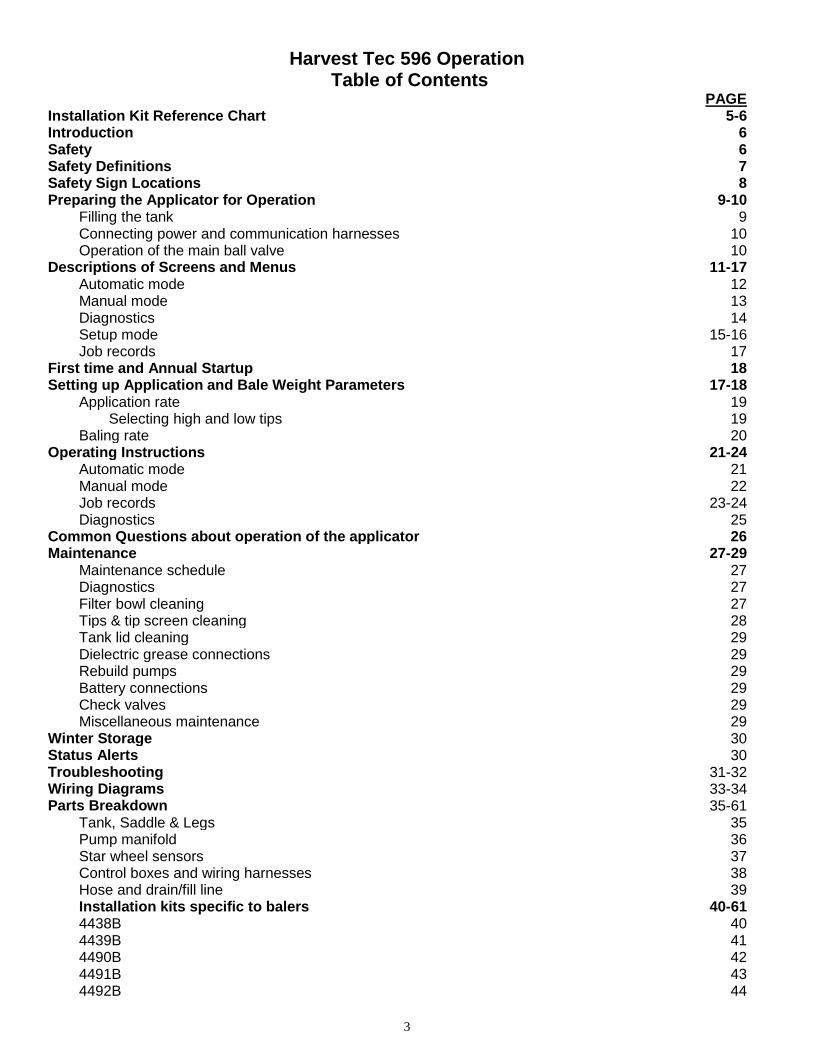
Harvest Tec 596 Operation Table of Contents
PAGE Installation Kit Reference Chart 5-6 Introduction 6 Safety Safety Definitions
6 7
Safety Sign Locations 8 Preparing the Applicator for Operation 9-10 Filling the tank 9 Connecting power and communication harnesses 10 Operation of the main ball valve 10 Descriptions of Screens and Menus 11-17 Automatic mode 12 Manual mode 13 Diagnostics 14 Setup mode 15-16 Job records 17 First time and Annual Startup 18 Setting up Application and Bale Weight Parameters 17-18 Application rate 19 Selecting high and low tips 19 Baling rate 20 Operating Instructions 21-24 Automatic mode 21 Manual mode 22 Job records 23-24 Diagnostics 25 Common Questions about operation of the applicator 26 Maintenance 27-29 Maintenance schedule 27 Diagnostics 27 Filter bowl cleaning 27 Tips & tip screen cleaning 28 Tank lid cleaning 29 Dielectric grease connections 29 Rebuild pumps 29 Battery connections 29 Check valves 29 Miscellaneous maintenance 29 Winter Storage 30 Status Alerts 30 Troubleshooting 31-32 Wiring Diagrams 33-34 Parts Breakdown 35-61 Tank, Saddle & Legs 35 Pump manifold 36 Star wheel sensors 37 Control boxes and wiring harnesses 38 Hose and drain/fill line 39 Installation kits specific to balers
4438B 4439B 4490B 4491B 4492B
40-61 40 41 42 43 44

4
4494B 4495B & 4528B 4497B &4529B 4498B 4499B 4500B 4501B 4509B 4510B 4511B 4514B 4515B 4518B 4519B 4525B 4527B 4530B
45 46 47 48 49 50 51 52 53 54 55 56 57 58 59 60 61
Vicon Large Square Template 62 Notes 63 Warranty statement Back page
5
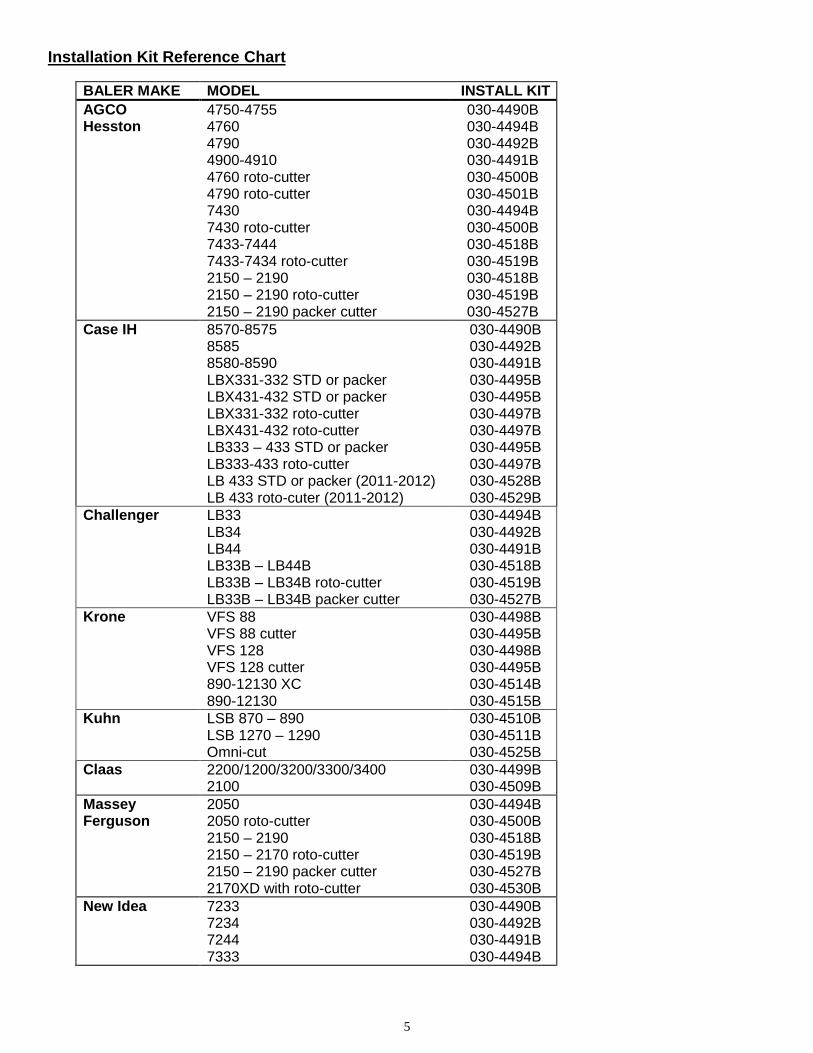
Installation Kit Reference Chart
BALER MAKE MODEL INSTALL KIT
AGCO Hesston
4750-4755 4760 4790 4900-4910 4760 roto-cutter 4790 roto-cutter 7430 7430 roto-cutter 7433-7444 7433-7434 roto-cutter 2150 – 2190 2150 – 2190 roto-cutter 2150 – 2190 packer cutter
030-4490B 030-4494B 030-4492B 030-4491B 030-4500B 030-4501B 030-4494B 030-4500B 030-4518B 030-4519B 030-4518B 030-4519B 030-4527B
Case IH 8570-8575 8585 8580-8590 LBX331-332 STD or packer LBX431-432 STD or packer LBX331-332 roto-cutter LBX431-432 roto-cutter LB333 – 433 STD or packer LB333-433 roto-cutter LB 433 STD or packer (2011-2012) LB 433 roto-cuter (2011-2012)
030-4490B 030-4492B 030-4491B 030-4495B 030-4495B 030-4497B 030-4497B 030-4495B 030-4497B 030-4528B 030-4529B
Challenger LB33 LB34 LB44 LB33B – LB44B LB33B – LB34B roto-cutter LB33B – LB34B packer cutter
030-4494B 030-4492B 030-4491B 030-4518B 030-4519B 030-4527B
Krone VFS 88 VFS 88 cutter VFS 128 VFS 128 cutter 890-12130 XC 890-12130
030-4498B 030-4495B 030-4498B 030-4495B 030-4514B 030-4515B
Kuhn LSB 870 – 890 LSB 1270 – 1290 Omni-cut
030-4510B 030-4511B 030-4525B
Claas
2200/1200/3200/3300/3400 2100
030-4499B 030-4509B
Massey Ferguson
2050 2050 roto-cutter 2150 – 2190 2150 – 2170 roto-cutter 2150 – 2190 packer cutter 2170XD with roto-cutter
030-4494B 030-4500B 030-4518B 030-4519B 030-4527B 030-4530B
New Idea 7233 7234 7244 7333
030-4490B 030-4492B 030-4491B 030-4494B
6
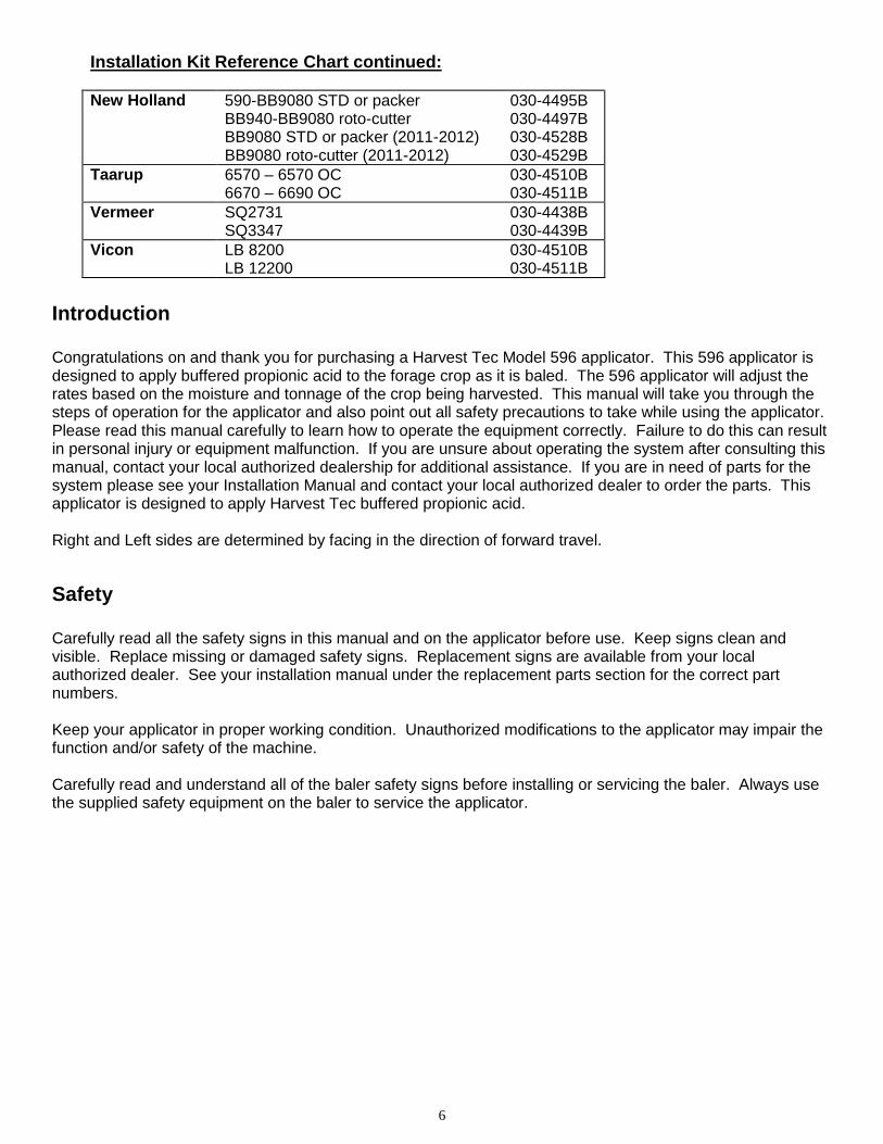
Installation Kit Reference Chart continued:
New Holland 590-BB9080 STD or packer BB940-BB9080 roto-cutter BB9080 STD or packer (2011-2012) BB9080 roto-cutter (2011-2012)
030-4495B 030-4497B 030-4528B 030-4529B
Taarup 6570 – 6570 OC 6670 – 6690 OC
030-4510B 030-4511B
Vermeer SQ2731 SQ3347
030-4438B 030-4439B
Vicon LB 8200 LB 12200
030-4510B 030-4511B
Introduction Congratulations on and thank you for purchasing a Harvest Tec Model 596 applicator. This 596 applicator is designed to apply buffered propionic acid to the forage crop as it is baled. The 596 applicator will adjust the rates based on the moisture and tonnage of the crop being harvested. This manual will take you through the steps of operation for the applicator and also point out all safety precautions to take while using the applicator. Please read this manual carefully to learn how to operate the equipment correctly. Failure to do this can result in personal injury or equipment malfunction. If you are unsure about operating the system after consulting this manual, contact your local authorized dealership for additional assistance. If you are in need of parts for the system please see your Installation Manual and contact your local authorized dealer to order the parts. This applicator is designed to apply Harvest Tec buffered propionic acid. Right and Left sides are determined by facing in the direction of forward travel.
Safety Carefully read all the safety signs in this manual and on the applicator before use. Keep signs clean and visible. Replace missing or damaged safety signs. Replacement signs are available from your local authorized dealer. See your installation manual under the replacement parts section for the correct part numbers. Keep your applicator in proper working condition. Unauthorized modifications to the applicator may impair the function and/or safety of the machine. Carefully read and understand all of the baler safety signs before installing or servicing the baler. Always use the supplied safety equipment on the baler to service the applicator.
7
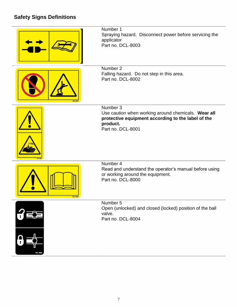
Safety Signs Definitions
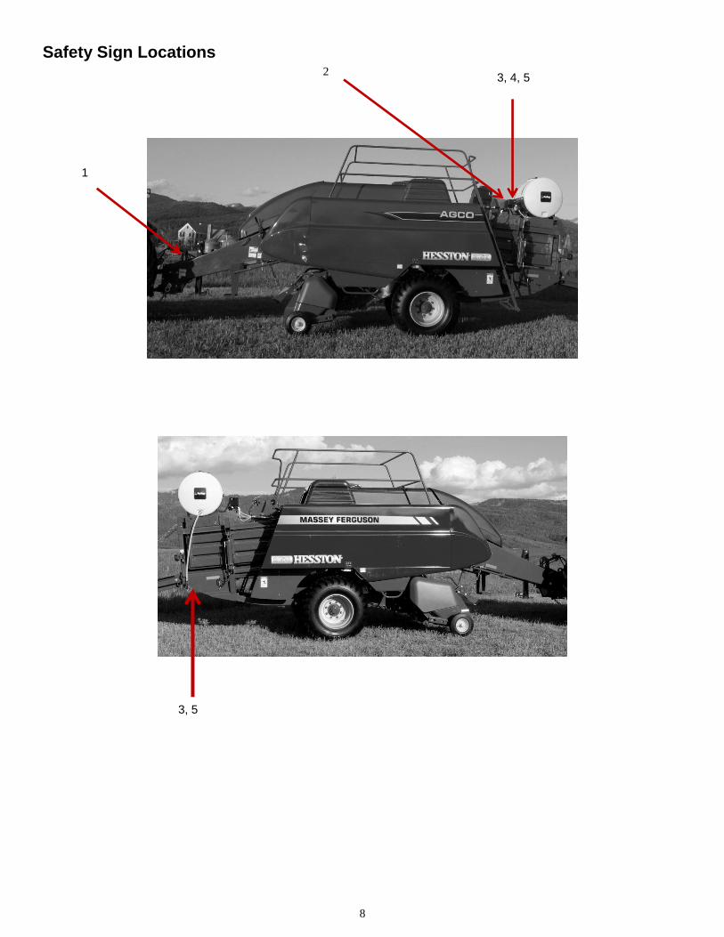
Number 1 Spraying hazard. Disconnect power before servicing the applicator Part no. DCL-8003
Number 2 Falling hazard. Do not step in this area. Part no. DCL-8002
Number 3 Use caution when working around chemicals. Wear all protective equipment according to the label of the product. Part no. DCL-8001
Number 4 Read and understand the operator’s manual before using or working around the equipment. Part no. DCL-8000
Number 5 Open (unlocked) and closed (locked) position of the ball valve. Part no. DCL-8004
8
Safety Sign Locations
3, 4, 5
1
2
3, 5
9
Preparing the applicator for operation
After the Applicator has been installed on the baler, please follow the steps below to prepare for operating the applicator both safely and correctly.
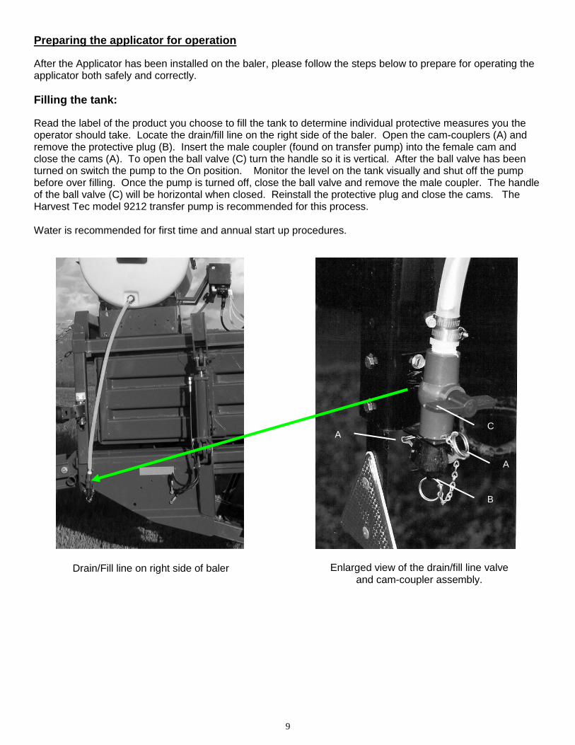
Filling the tank:
Read the label of the product you choose to fill the tank to determine individual protective measures you the operator should take. Locate the drain/fill line on the right side of the baler. Open the cam-couplers (A) and remove the protective plug (B). Insert the male coupler (found on transfer pump) into the female cam and close the cams (A). To open the ball valve (C) turn the handle so it is vertical. After the ball valve has been turned on switch the pump to the On position. Monitor the level on the tank visually and shut off the pump before over filling. Once the pump is turned off, close the ball valve and remove the male coupler. The handle of the ball valve (C) will be horizontal when closed. Reinstall the protective plug and close the cams. The Harvest Tec model 9212 transfer pump is recommended for this process. Water is recommended for first time and annual start up procedures.
Drain/Fill line on right side of baler
A
A
B
C
Enlarged view of the drain/fill line valve and cam-coupler assembly.
10
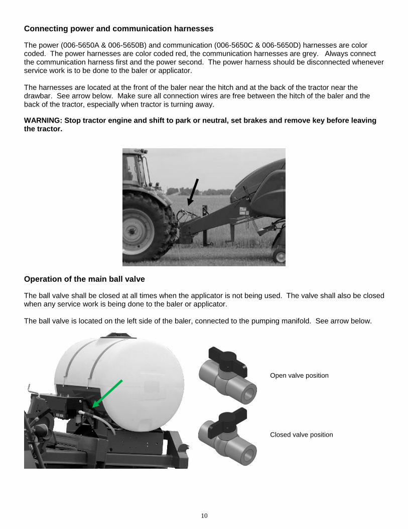
Connecting power and communication harnesses
The power (006-5650A & 006-5650B) and communication (006-5650C & 006-5650D) harnesses are color coded. The power harnesses are color coded red, the communication harnesses are grey. Always connect the communication harness first and the power second. The power harness should be disconnected whenever service work is to be done to the baler or applicator. The harnesses are located at the front of the baler near the hitch and at the back of the tractor near the drawbar. See arrow below. Make sure all connection wires are free between the hitch of the baler and the back of the tractor, especially when tractor is turning away.
WARNING: Stop tractor engine and shift to park or neutral, set brakes and remove key before leaving the tractor.
Operation of the main ball valve
The ball valve shall be closed at all times when the applicator is not being used. The valve shall also be closed when any service work is being done to the baler or applicator. The ball valve is located on the left side of the baler, connected to the pumping manifold. See arrow below.
Open valve position
Closed valve position
11
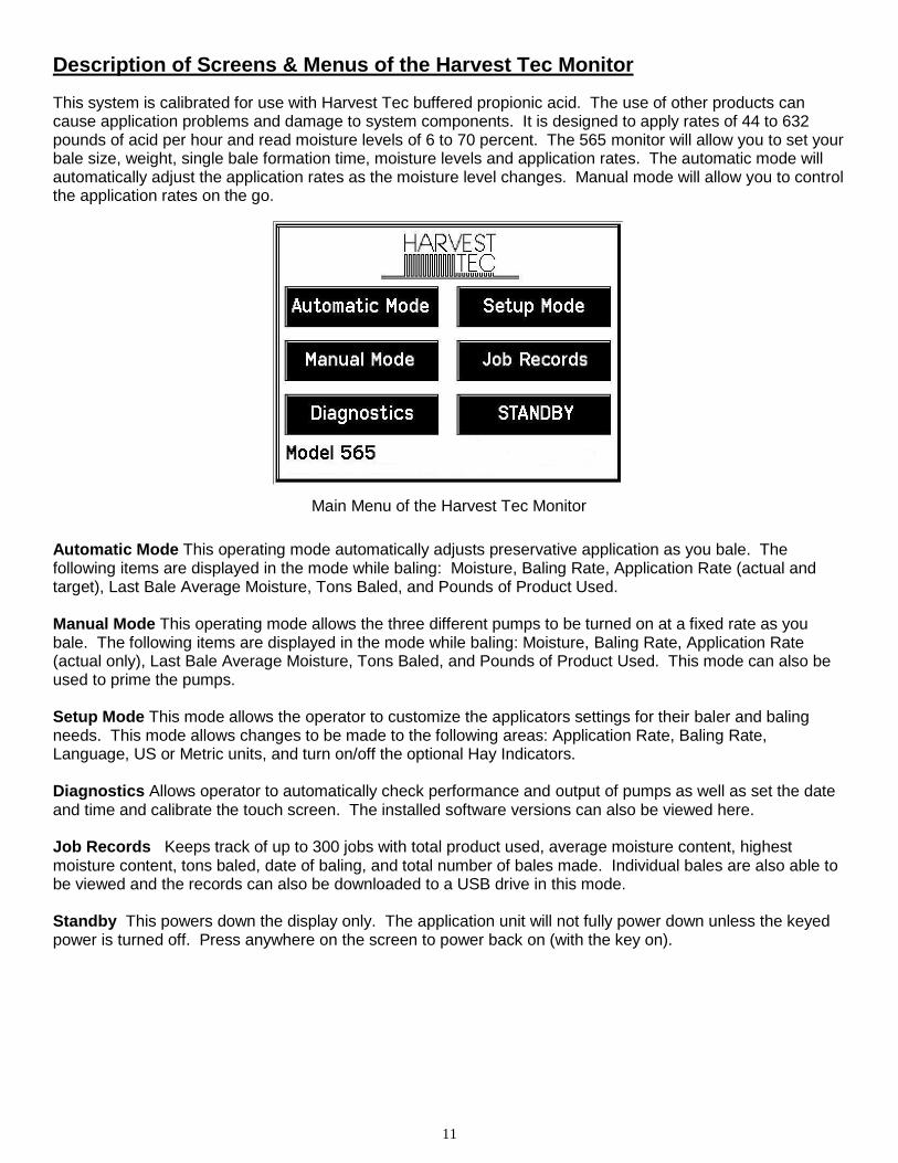
Description of Screens & Menus of the Harvest Tec Monitor
This system is calibrated for use with Harvest Tec buffered propionic acid. The use of other products can cause application problems and damage to system components. It is designed to apply rates of 44 to 632 pounds of acid per hour and read moisture levels of 6 to 70 percent. The 565 monitor will allow you to set your bale size, weight, single bale formation time, moisture levels and application rates. The automatic mode will automatically adjust the application rates as the moisture level changes. Manual mode will allow you to control the application rates on the go.
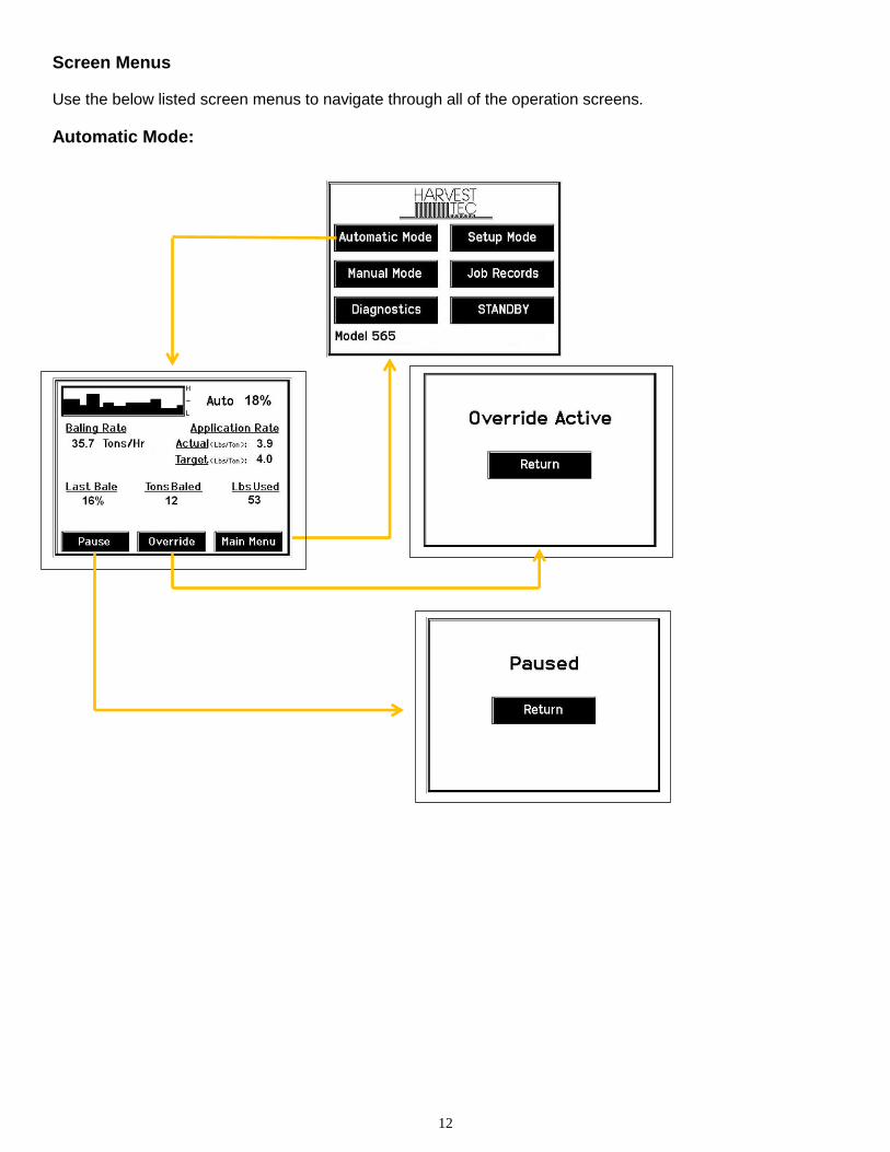
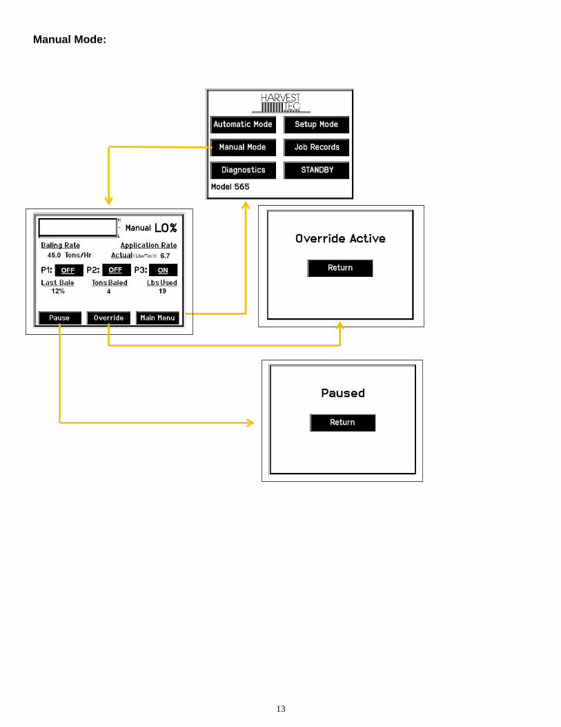
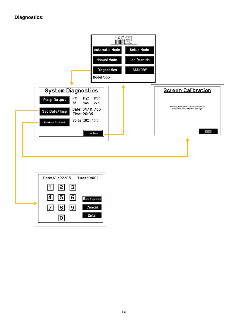
Automatic Mode This operating mode automatically adjusts preservative application as you bale. The following items are displayed in the mode while baling: Moisture, Baling Rate, Application Rate (actual and target), Last Bale Average Moisture, Tons Baled, and Pounds of Product Used. Manual Mode This operating mode allows the three different pumps to be turned on at a fixed rate as you bale. The following items are displayed in the mode while baling: Moisture, Baling Rate, Application Rate (actual only), Last Bale Average Moisture, Tons Baled, and Pounds of Product Used. This mode can also be used to prime the pumps. Setup Mode This mode allows the operator to customize the applicators settings for their baler and baling needs. This mode allows changes to be made to the following areas: Application Rate, Baling Rate, Language, US or Metric units, and turn on/off the optional Hay Indicators. Diagnostics Allows operator to automatically check performance and output of pumps as well as set the date and time and calibrate the touch screen. The installed software versions can also be viewed here. Job Records Keeps track of up to 300 jobs with total product used, average moisture content, highest moisture content, tons baled, date of baling, and total number of bales made. Individual bales are also able to be viewed and the records can also be downloaded to a USB drive in this mode. Standby This powers down the display only. The application unit will not fully power down unless the keyed power is turned off. Press anywhere on the screen to power back on (with the key on).
Main Menu of the Harvest Tec Monitor
12
Screen Menus
Use the below listed screen menus to navigate through all of the operation screens.
Automatic Mode:
13
Manual Mode:
14
Diagnostics:
15
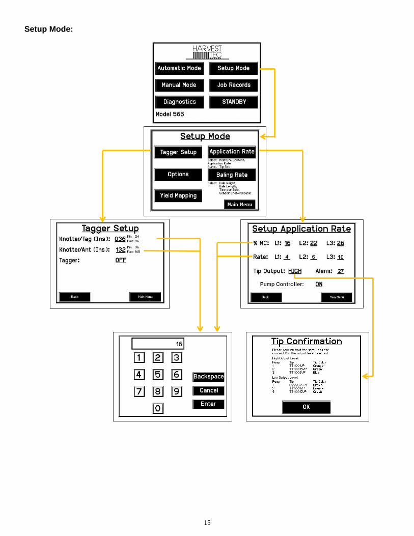
Setup Mode:
16
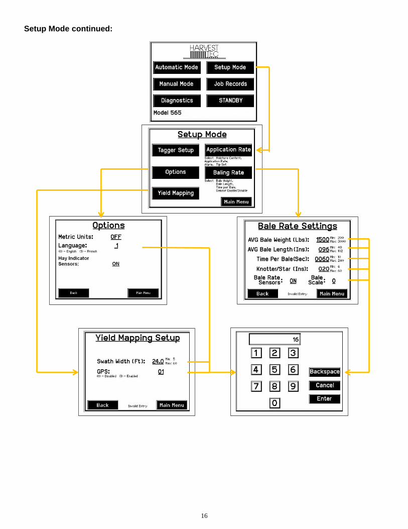
Setup Mode continued:
17
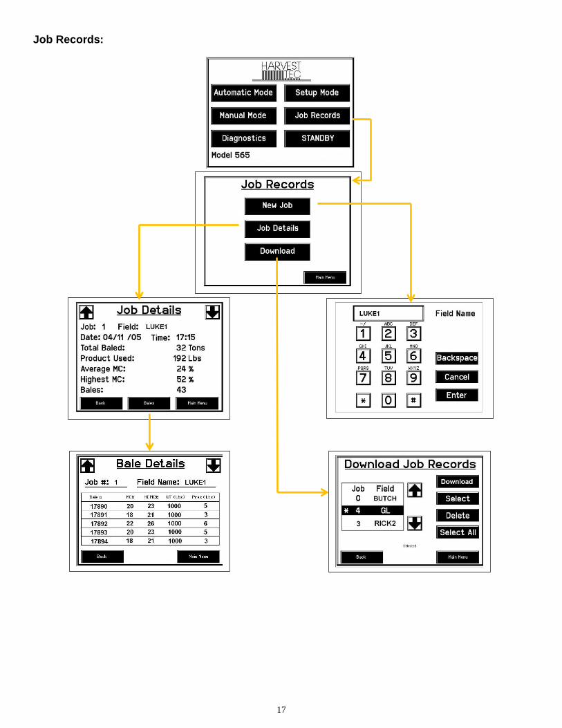
Job Records:
18
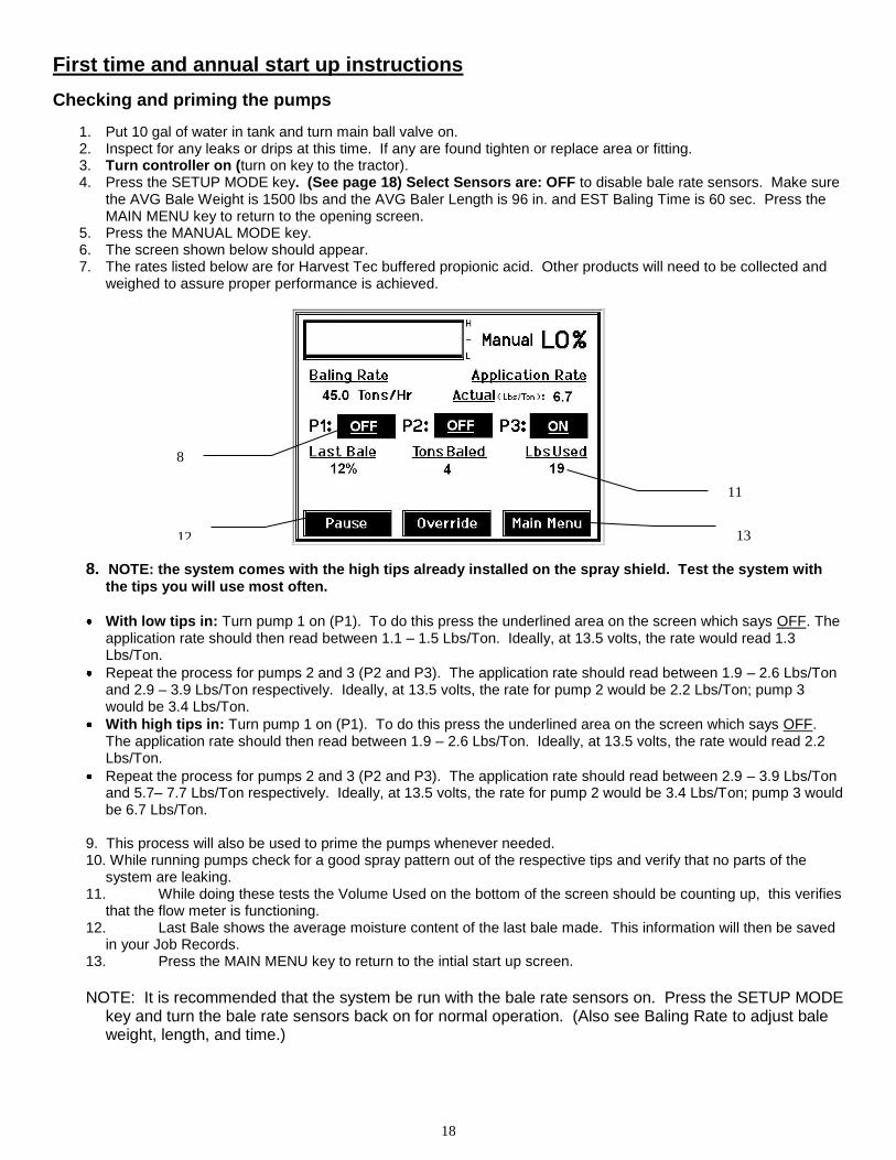
First time and annual start up instructions
Checking and priming the pumps
1. Put 10 gal of water in tank and turn main ball valve on. 2. Inspect for any leaks or drips at this time. If any are found tighten or replace area or fitting. 3. Turn controller on (turn on key to the tractor). 4. Press the SETUP MODE key. (See page 18) Select Sensors are: OFF to disable bale rate sensors. Make sure
the AVG Bale Weight is 1500 lbs and the AVG Baler Length is 96 in. and EST Baling Time is 60 sec. Press the MAIN MENU key to return to the opening screen.
5. Press the MANUAL MODE key. 6. The screen shown below should appear. 7. The rates listed below are for Harvest Tec buffered propionic acid. Other products will need to be collected and
weighed to assure proper performance is achieved.
8. NOTE: the system comes with the high tips already installed on the spray shield. Test the system with
the tips you will use most often.
With low tips in: Turn pump 1 on (P1). To do this press the underlined area on the screen which says OFF. The application rate should then read between 1.1 – 1.5 Lbs/Ton. Ideally, at 13.5 volts, the rate would read 1.3 Lbs/Ton.
Repeat the process for pumps 2 and 3 (P2 and P3). The application rate should read between 1.9 – 2.6 Lbs/Ton and 2.9 – 3.9 Lbs/Ton respectively. Ideally, at 13.5 volts, the rate for pump 2 would be 2.2 Lbs/Ton; pump 3 would be 3.4 Lbs/Ton.
With high tips in: Turn pump 1 on (P1). To do this press the underlined area on the screen which says OFF. The application rate should then read between 1.9 – 2.6 Lbs/Ton. Ideally, at 13.5 volts, the rate would read 2.2 Lbs/Ton.
Repeat the process for pumps 2 and 3 (P2 and P3). The application rate should read between 2.9 – 3.9 Lbs/Ton and 5.7– 7.7 Lbs/Ton respectively. Ideally, at 13.5 volts, the rate for pump 2 would be 3.4 Lbs/Ton; pump 3 would be 6.7 Lbs/Ton.
9. This process will also be used to prime the pumps whenever needed. 10. While running pumps check for a good spray pattern out of the respective tips and verify that no parts of the
system are leaking. 11. While doing these tests the Volume Used on the bottom of the screen should be counting up, this verifies
that the flow meter is functioning. 12. Last Bale shows the average moisture content of the last bale made. This information will then be saved
in your Job Records. 13. Press the MAIN MENU key to return to the intial start up screen.
NOTE: It is recommended that the system be run with the bale rate sensors on. Press the SETUP MODE
key and turn the bale rate sensors back on for normal operation. (Also see Baling Rate to adjust bale weight, length, and time.)
8
11
13 12
19
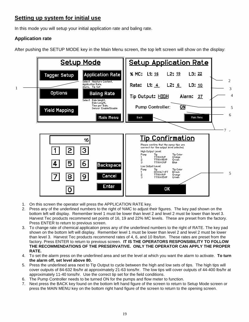
Setting up system for initial use
In this mode you will setup your initial application rate and baling rate.
Application rate After pushing the SETUP MODE key in the Main Menu screen, the top left screen will show on the display:
1. On this screen the operator will press the APPLICATION RATE key. 2. Press any of the underlined numbers to the right of %MC to adjust their figures. The key pad shown on the
bottom left will display. Remember level 1 must be lower than level 2 and level 2 must be lower than level 3. Harvest Tec products recommend set points of 16, 19 and 22% MC levels. These are preset from the factory. Press ENTER to return to previous screen.
3. To change rate of chemical application press any of the underlined numbers to the right of RATE. The key pad shown on the bottom left will display. Remember level 1 must be lower than level 2 and level 2 must be lower than level 3. Harvest Tec products recommend rates of 4, 6, and 10 lbs/ton. These rates are preset from the factory. Press ENTER to return to previous screen. IT IS THE OPERATORS RESPONSIBILITY TO FOLLOW THE RECOMMENDATIONS OF THE PRESERVATIVE. ONLY THE OPERATOR CAN APPLY THE PROPER RATE.
4. To set the alarm press on the underlined area and set the level at which you want the alarm to activate. To turn the alarm off, set level above 80.
5. Press the underlined area next to Tip Output to cycle between the high and low sets of tips. The high tips will cover outputs of 84-632 lbs/hr at approximately 21-63 tons/hr. The low tips will cover outputs of 44-400 lbs/hr at approximately 11-40 tons/hr. Use the correct tip set for the field conditions.
6. The Pump Controller needs to be turned ON for the pumps and flow meter to function. 7. Next press the BACK key found on the bottom left hand figure of the screen to return to Setup Mode screen or
press the MAIN MENU key on the bottom right hand figure of the screen to return to the opening screen.
2
4
5
7
3
5
6
7
1
20
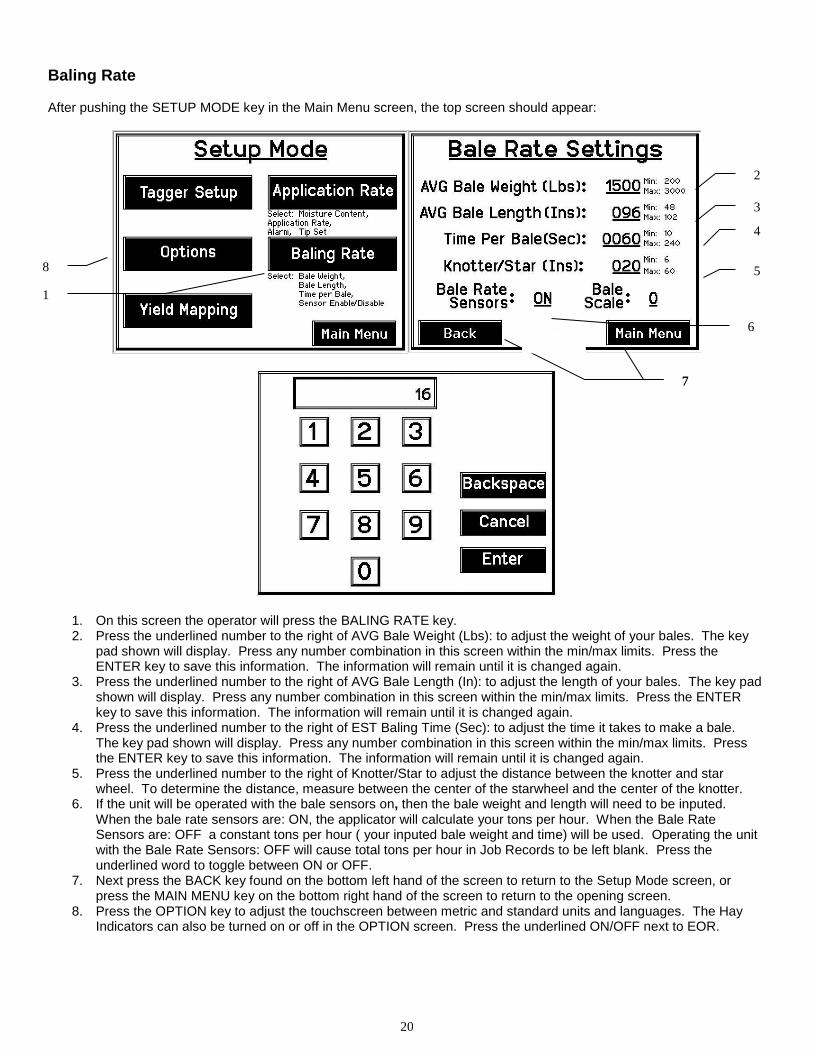
Baling Rate After pushing the SETUP MODE key in the Main Menu screen, the top screen should appear:
1. On this screen the operator will press the BALING RATE key. 2. Press the underlined number to the right of AVG Bale Weight (Lbs): to adjust the weight of your bales. The key
pad shown will display. Press any number combination in this screen within the min/max limits. Press the ENTER key to save this information. The information will remain until it is changed again.
3. Press the underlined number to the right of AVG Bale Length (In): to adjust the length of your bales. The key pad shown will display. Press any number combination in this screen within the min/max limits. Press the ENTER key to save this information. The information will remain until it is changed again.
4. Press the underlined number to the right of EST Baling Time (Sec): to adjust the time it takes to make a bale. The key pad shown will display. Press any number combination in this screen within the min/max limits. Press the ENTER key to save this information. The information will remain until it is changed again.
5. Press the underlined number to the right of Knotter/Star to adjust the distance between the knotter and star wheel. To determine the distance, measure between the center of the starwheel and the center of the knotter.
6. If the unit will be operated with the bale sensors on, then the bale weight and length will need to be inputed. When the bale rate sensors are: ON, the applicator will calculate your tons per hour. When the Bale Rate Sensors are: OFF a constant tons per hour ( your inputed bale weight and time) will be used. Operating the unit with the Bale Rate Sensors: OFF will cause total tons per hour in Job Records to be left blank. Press the underlined word to toggle between ON or OFF.
7. Next press the BACK key found on the bottom left hand of the screen to return to the Setup Mode screen, or press the MAIN MENU key on the bottom right hand of the screen to return to the opening screen.
8. Press the OPTION key to adjust the touchscreen between metric and standard units and languages. The Hay Indicators can also be turned on or off in the OPTION screen. Press the underlined ON/OFF next to EOR.
1
2
3
4
5
6
7 7
8
21
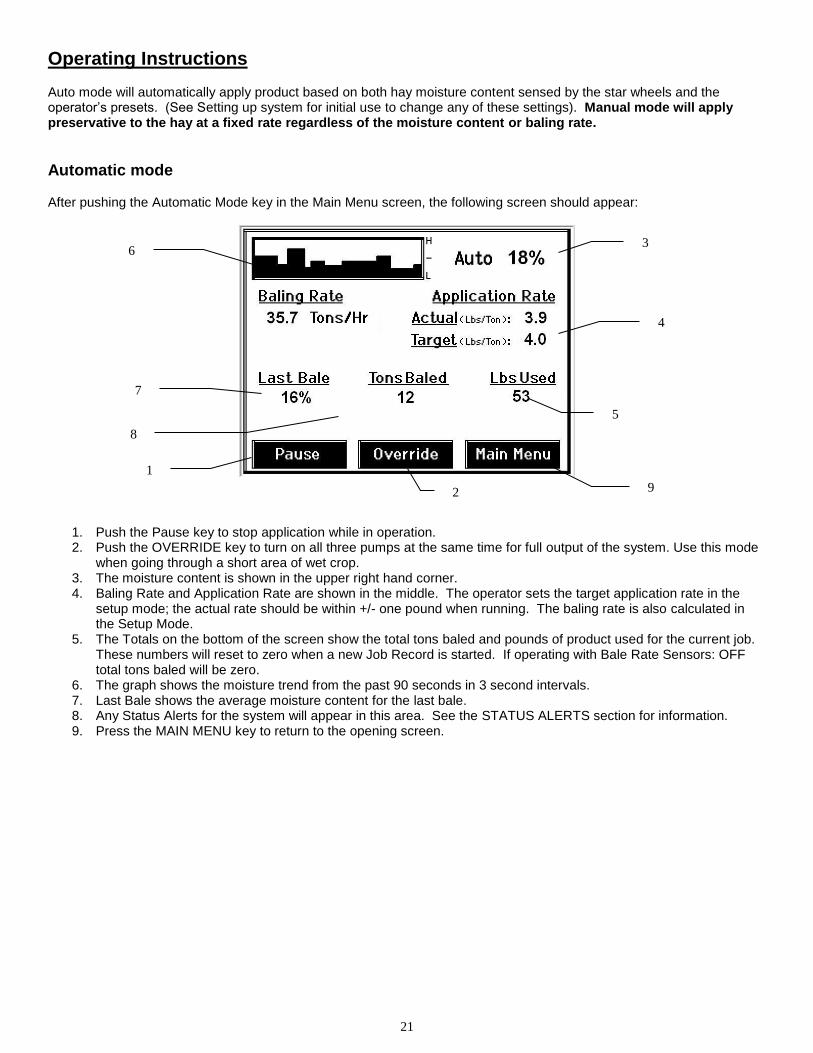
Operating Instructions Auto mode will automatically apply product based on both hay moisture content sensed by the star wheels and the operator’s presets. (See Setting up system for initial use to change any of these settings). Manual mode will apply preservative to the hay at a fixed rate regardless of the moisture content or baling rate.
Automatic mode After pushing the Automatic Mode key in the Main Menu screen, the following screen should appear:
1. Push the Pause key to stop application while in operation. 2. Push the OVERRIDE key to turn on all three pumps at the same time for full output of the system. Use this mode
when going through a short area of wet crop. 3. The moisture content is shown in the upper right hand corner. 4. Baling Rate and Application Rate are shown in the middle. The operator sets the target application rate in the
setup mode; the actual rate should be within +/- one pound when running. The baling rate is also calculated in the Setup Mode.
5. The Totals on the bottom of the screen show the total tons baled and pounds of product used for the current job. These numbers will reset to zero when a new Job Record is started. If operating with Bale Rate Sensors: OFF total tons baled will be zero.
6. The graph shows the moisture trend from the past 90 seconds in 3 second intervals. 7. Last Bale shows the average moisture content for the last bale. 8. Any Status Alerts for the system will appear in this area. See the STATUS ALERTS section for information. 9. Press the MAIN MENU key to return to the opening screen.
1
2
3
4
5
6
9
7
8
22
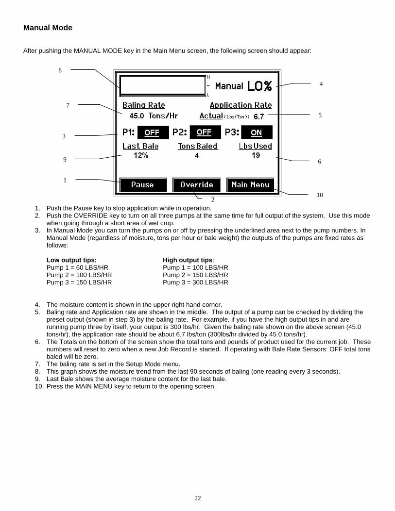
Manual Mode
After pushing the MANUAL MODE key in the Main Menu screen, the following screen should appear:
1. Push the Pause key to stop application while in operation. 2. Push the OVERRIDE key to turn on all three pumps at the same time for full output of the system. Use this mode
when going through a short area of wet crop. 3. In Manual Mode you can turn the pumps on or off by pressing the underlined area next to the pump numbers. In
Manual Mode (regardless of moisture, tons per hour or bale weight) the outputs of the pumps are fixed rates as follows:
Low output tips: High output tips: Pump 1 = 60 LBS/HR Pump 1 = 100 LBS/HR Pump 2 = 100 LBS/HR Pump 2 = 150 LBS/HR Pump 3 = 150 LBS/HR Pump 3 = 300 LBS/HR
4. The moisture content is shown in the upper right hand corner. 5. Baling rate and Application rate are shown in the middle. The output of a pump can be checked by dividing the
preset output (shown in step 3) by the baling rate. For example, if you have the high output tips in and are running pump three by itself, your output is 300 lbs/hr. Given the baling rate shown on the above screen (45.0 tons/hr), the application rate should be about 6.7 lbs/ton (300lbs/hr divided by 45.0 tons/hr).
6. The Totals on the bottom of the screen show the total tons and pounds of product used for the current job. These numbers will reset to zero when a new Job Record is started. If operating with Bale Rate Sensors: OFF total tons baled will be zero.
7. The baling rate is set in the Setup Mode menu. 8. This graph shows the moisture trend from the last 90 seconds of baling (one reading every 3 seconds). 9. Last Bale shows the average moisture content for the last bale. 10. Press the MAIN MENU key to return to the opening screen.
1
2
3
4
5
6
7
8
10
9
23
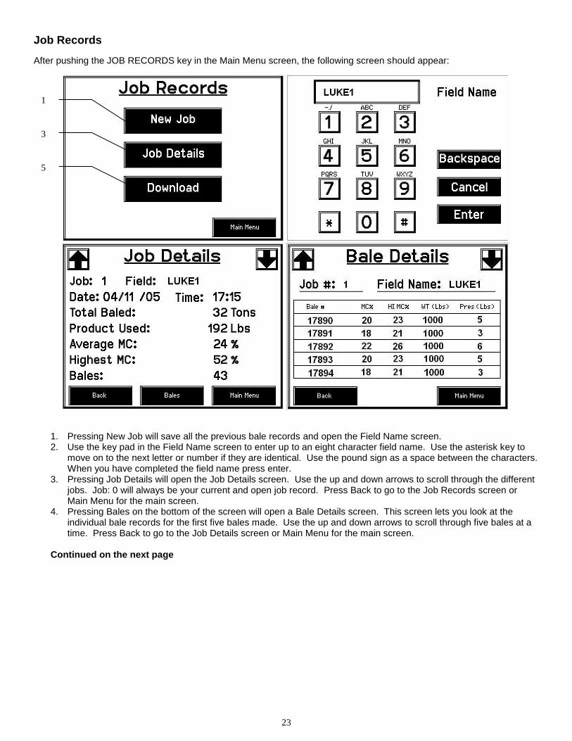
Job Records
After pushing the JOB RECORDS key in the Main Menu screen, the following screen should appear:
1. Pressing New Job will save all the previous bale records and open the Field Name screen. 2. Use the key pad in the Field Name screen to enter up to an eight character field name. Use the asterisk key to
move on to the next letter or number if they are identical. Use the pound sign as a space between the characters. When you have completed the field name press enter.
3. Pressing Job Details will open the Job Details screen. Use the up and down arrows to scroll through the different jobs. Job: 0 will always be your current and open job record. Press Back to go to the Job Records screen or Main Menu for the main screen.
4. Pressing Bales on the bottom of the screen will open a Bale Details screen. This screen lets you look at the individual bale records for the first five bales made. Use the up and down arrows to scroll through five bales at a time. Press Back to go to the Job Details screen or Main Menu for the main screen.
Continued on the next page
1
3
5
24
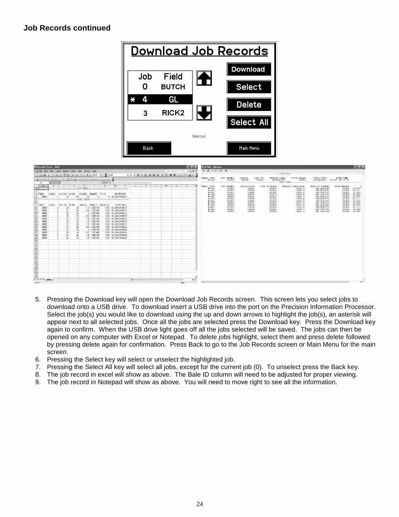
Job Records continued
5. Pressing the Download key will open the Download Job Records screen. This screen lets you select jobs to download onto a USB drive. To download insert a USB drive into the port on the Precision Information Processor. Select the job(s) you would like to download using the up and down arrows to highlight the job(s), an asterisk will appear next to all selected jobs. Once all the jobs are selected press the Download key. Press the Download key again to confirm. When the USB drive light goes off all the jobs selected will be saved. The jobs can then be opened on any computer with Excel or Notepad. To delete jobs highlight, select them and press delete followed by pressing delete again for confirmation. Press Back to go to the Job Records screen or Main Menu for the main screen.
6. Pressing the Select key will select or unselect the highlighted job. 7. Pressing the Select All key will select all jobs, except for the current job (0). To unselect press the Back key. 8. The job record in excel will show as above. The Bale ID column will need to be adjusted for proper viewing. 9. The job record in Notepad will show as above. You will need to move right to see all the information.
25
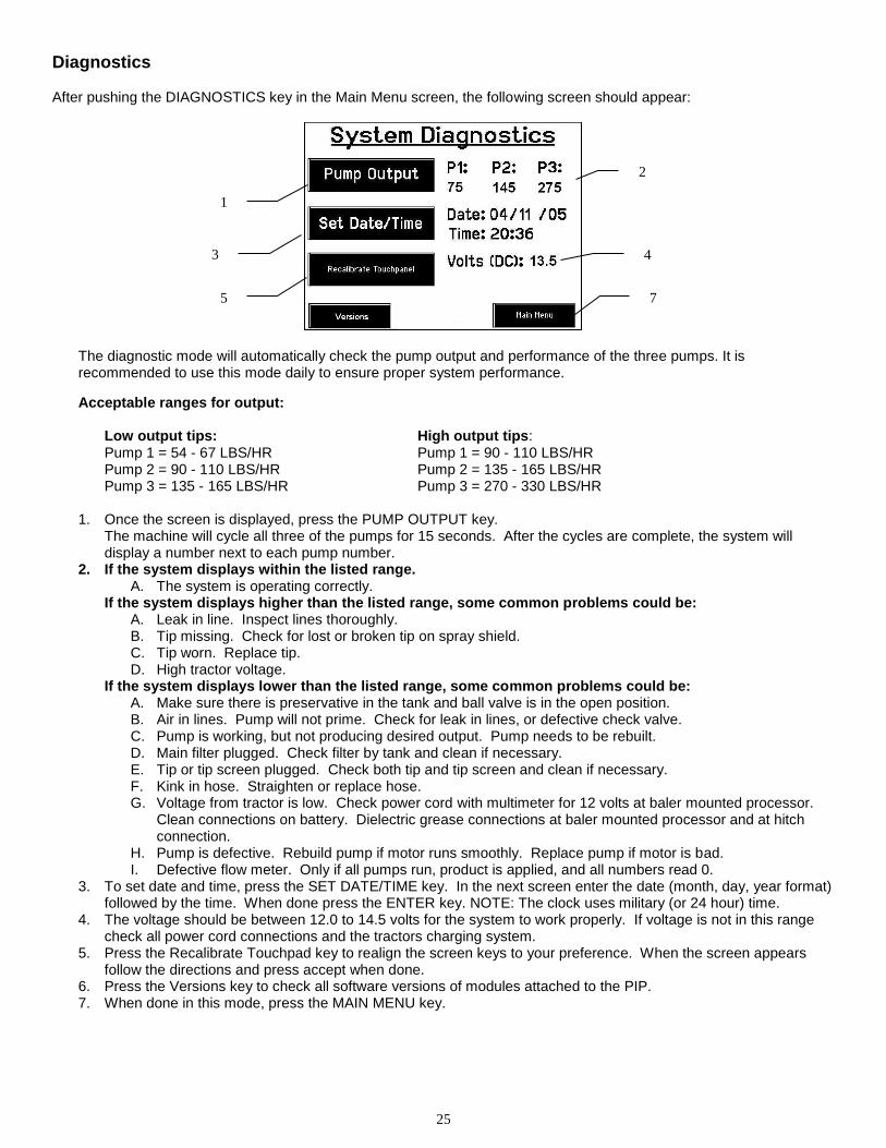
Diagnostics After pushing the DIAGNOSTICS key in the Main Menu screen, the following screen should appear:
The diagnostic mode will automatically check the pump output and performance of the three pumps. It is recommended to use this mode daily to ensure proper system performance.
Acceptable ranges for output:
Low output tips: High output tips: Pump 1 = 54 - 67 LBS/HR Pump 1 = 90 - 110 LBS/HR Pump 2 = 90 - 110 LBS/HR Pump 2 = 135 - 165 LBS/HR Pump 3 = 135 - 165 LBS/HR Pump 3 = 270 - 330 LBS/HR
1. Once the screen is displayed, press the PUMP OUTPUT key.
The machine will cycle all three of the pumps for 15 seconds. After the cycles are complete, the system will display a number next to each pump number.
2. If the system displays within the listed range. A. The system is operating correctly.
If the system displays higher than the listed range, some common problems could be: A. Leak in line. Inspect lines thoroughly. B. Tip missing. Check for lost or broken tip on spray shield. C. Tip worn. Replace tip. D. High tractor voltage.
If the system displays lower than the listed range, some common problems could be: A. Make sure there is preservative in the tank and ball valve is in the open position. B. Air in lines. Pump will not prime. Check for leak in lines, or defective check valve. C. Pump is working, but not producing desired output. Pump needs to be rebuilt. D. Main filter plugged. Check filter by tank and clean if necessary. E. Tip or tip screen plugged. Check both tip and tip screen and clean if necessary. F. Kink in hose. Straighten or replace hose. G. Voltage from tractor is low. Check power cord with multimeter for 12 volts at baler mounted processor.
Clean connections on battery. Dielectric grease connections at baler mounted processor and at hitch connection.
H. Pump is defective. Rebuild pump if motor runs smoothly. Replace pump if motor is bad. I. Defective flow meter. Only if all pumps run, product is applied, and all numbers read 0.
3. To set date and time, press the SET DATE/TIME key. In the next screen enter the date (month, day, year format) followed by the time. When done press the ENTER key. NOTE: The clock uses military (or 24 hour) time.
4. The voltage should be between 12.0 to 14.5 volts for the system to work properly. If voltage is not in this range check all power cord connections and the tractors charging system.
5. Press the Recalibrate Touchpad key to realign the screen keys to your preference. When the screen appears follow the directions and press accept when done.
6. Press the Versions key to check all software versions of modules attached to the PIP. 7. When done in this mode, press the MAIN MENU key.
1
3
7
2
4
5
26
Common Questions about the 565
1. How do I turn the system on/off? Turn the key in the tractor to the on position. If the unit is in Standby Mode, press anywhere on the screen. To turn off, press the Standby key, wait for the screen to power down and turn off the key.
2. How to get in the LBS/TON, MC%, and TONS/HR menus?
In the Main Menu press the SETUP MODE key. From this screen you can change your application rates and how much product is applied. See SETTING UP FOR INITIAL USE for a detailed explanation of this process.
3. The unit is stuck in the MC% screen.
In the MC% screen, level 1 must be less than level 2, and level 2 must be less than level 3. For example, if level 1 is set at 16, level 2 must be set at 17 or higher, and level 3 must be set higher than level 2.
4. How does OVERRIDE work?
Override turns on all three pumps at full output. The pumps will remain at full output until the operator turns these pumps off by pressing the OVERRIDE key again.
5. The flow meter reading is more or less than the programmed level set in the box.
Some variation in flow meter readings compared to the programmed set point is normal due to factory tolerances on the pump motors as well as varying tractor voltages inputted to the control box. The flow meter reading is an accurate measure of how much product is actually being applied. The set points then will need to be adjusted if you want to attain a different flow meter reading.
6. Why don’t all the pumps turn on even at higher application rates?
The selections of what pumps turn on when are automatically controlled by the control box’s flow rate look up chart. Thus, not all the pumps turn on at once and the combination of what pumps turn on when is automatically controlled by the software. If you want to make sure all three pumps are working, go to the Diagnostics screen and run pump outputs.
7. The moisture content displays “LO” or “HI” all the time.
When the moisture content display does not change frequently while baling, there is likely a faulty star wheel connection. One of the first places to check is inside the white star wheel block. Check to see if the electronic swivel is in the star wheel shaft and check to see that the star wheel shaft is not working out of the block. Also, check all star wheel wires and connectors to see if there is a continuity or grounding problem.
8. Should the battery connections be removed before jump starting or charging a battery? Yes. Anytime the tractor will have voltage going up rapidly the connections should be removed.
9. How do I recalibrate the touch screen display? In the system diagnostics screen press the Recalibrate Touch screen key and follow the directions on the screen. Press accept when done.
10. How can I turn the optional Hay Indicators on/off from the cab?
In the Setup Mode screen press options. Press the on/off underlined area next to EOR sensor.
27
Maintenance
If you are unsure how to perform any of the maintenance steps have your local authorized dealer perform the tasks.
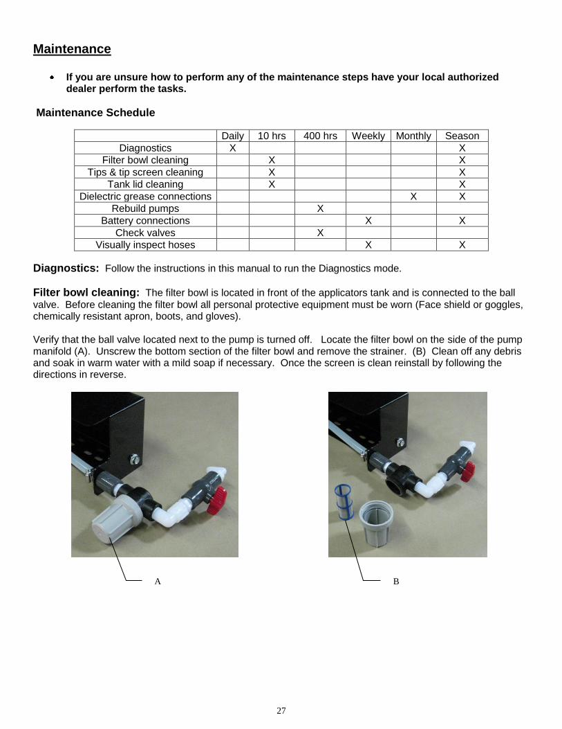
Maintenance Schedule
Daily 10 hrs 400 hrs Weekly Monthly Season
Diagnostics X X
Filter bowl cleaning X X
Tips & tip screen cleaning X X
Tank lid cleaning X X
Dielectric grease connections X X
Rebuild pumps X
Battery connections X X
Check valves X
Visually inspect hoses X X
Diagnostics: Follow the instructions in this manual to run the Diagnostics mode.
Filter bowl cleaning: The filter bowl is located in front of the applicators tank and is connected to the ball
valve. Before cleaning the filter bowl all personal protective equipment must be worn (Face shield or goggles, chemically resistant apron, boots, and gloves). Verify that the ball valve located next to the pump is turned off. Locate the filter bowl on the side of the pump manifold (A). Unscrew the bottom section of the filter bowl and remove the strainer. (B) Clean off any debris and soak in warm water with a mild soap if necessary. Once the screen is clean reinstall by following the directions in reverse.
A B
28
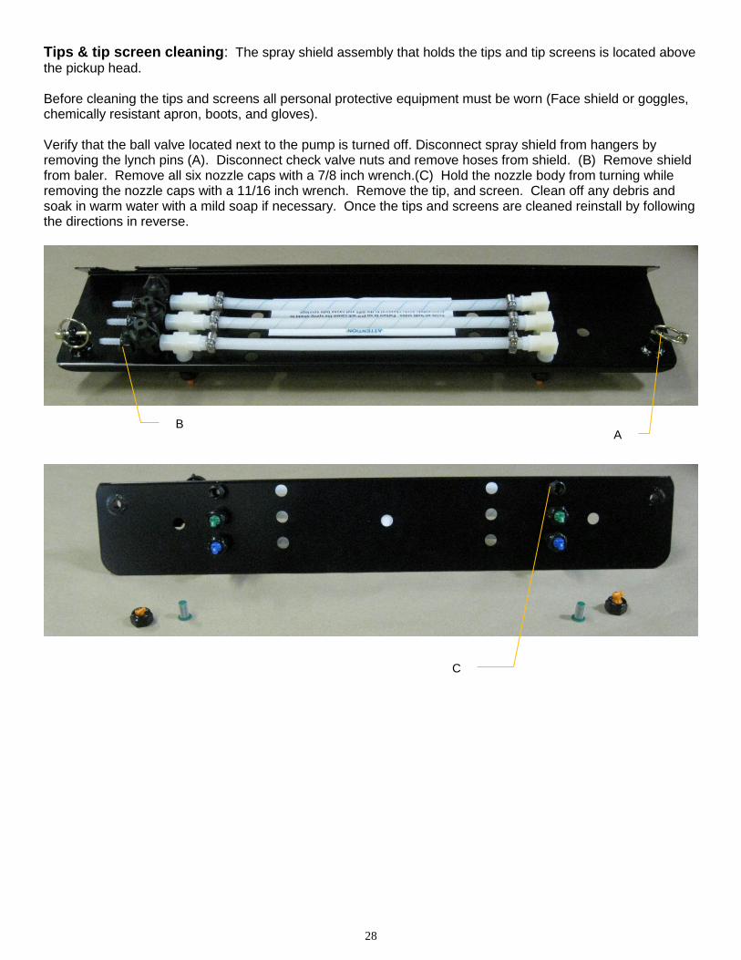
Tips & tip screen cleaning: The spray shield assembly that holds the tips and tip screens is located above
the pickup head. Before cleaning the tips and screens all personal protective equipment must be worn (Face shield or goggles, chemically resistant apron, boots, and gloves). Verify that the ball valve located next to the pump is turned off. Disconnect spray shield from hangers by removing the lynch pins (A). Disconnect check valve nuts and remove hoses from shield. (B) Remove shield from baler. Remove all six nozzle caps with a 7/8 inch wrench.(C) Hold the nozzle body from turning while removing the nozzle caps with a 11/16 inch wrench. Remove the tip, and screen. Clean off any debris and soak in warm water with a mild soap if necessary. Once the tips and screens are cleaned reinstall by following the directions in reverse.
A B
C
29
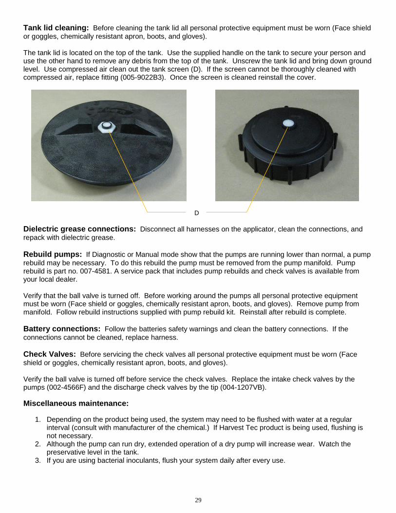
Tank lid cleaning: Before cleaning the tank lid all personal protective equipment must be worn (Face shield
or goggles, chemically resistant apron, boots, and gloves). The tank lid is located on the top of the tank. Use the supplied handle on the tank to secure your person and use the other hand to remove any debris from the top of the tank. Unscrew the tank lid and bring down ground level. Use compressed air clean out the tank screen (D). If the screen cannot be thoroughly cleaned with compressed air, replace fitting (005-9022B3). Once the screen is cleaned reinstall the cover.
Dielectric grease connections: Disconnect all harnesses on the applicator, clean the connections, and
repack with dielectric grease.
Rebuild pumps: If Diagnostic or Manual mode show that the pumps are running lower than normal, a pump
rebuild may be necessary. To do this rebuild the pump must be removed from the pump manifold. Pump rebuild is part no. 007-4581. A service pack that includes pump rebuilds and check valves is available from your local dealer. Verify that the ball valve is turned off. Before working around the pumps all personal protective equipment must be worn (Face shield or goggles, chemically resistant apron, boots, and gloves). Remove pump from manifold. Follow rebuild instructions supplied with pump rebuild kit. Reinstall after rebuild is complete.
Battery connections: Follow the batteries safety warnings and clean the battery connections. If the
connections cannot be cleaned, replace harness.
Check Valves: Before servicing the check valves all personal protective equipment must be worn (Face
shield or goggles, chemically resistant apron, boots, and gloves). Verify the ball valve is turned off before service the check valves. Replace the intake check valves by the pumps (002-4566F) and the discharge check valves by the tip (004-1207VB).
Miscellaneous maintenance:
1. Depending on the product being used, the system may need to be flushed with water at a regular interval (consult with manufacturer of the chemical.) If Harvest Tec product is being used, flushing is not necessary.
2. Although the pump can run dry, extended operation of a dry pump will increase wear. Watch the preservative level in the tank.
3. If you are using bacterial inoculants, flush your system daily after every use.
D
30
Winter Storage
1. Thoroughly flush the system with water. 2. Remove the filter bowl and run dry until the water has cleared out of the intake side. 3. Remove the red plug from the bottom of the pump, drain, and run the pump for 30 seconds or until it is
dry. 4. Drain all lines on the outlet side. 5. Never use oils or alcohol based anti-freeze in the system. 6. For spring start-up, if the pump is frozen, turn off the power immediately to avoid burning the motor out
or blowing a fuse. The pump head can be disassembled and freed or rebuilt in most cases. Check the fuses after the pump has been freed.
7. Disconnect power from the Precision Information Processor. 8. Remove display from tractor and store in a warm, dry place.
Status Alerts
Two Status Alerts will appear on the Auto and Manual mode screens when the Job Records are approaching, or full of records. Status Alert “Bale Records: Less than 1K remaining”. The system is now approaching the maximum amount of records that can be saved. When this code appears, download and delete jobs in the Job Records menu. Follow the instructions in Job Records to accomplish this. Status Alert “Bale Records failed – Memory Full”. The system will no longer accept any new data until jobs in the Job Records menu are downloaded and deleted. Follow the instructions in Job Records to accomplish this.

31
Troubleshooting Checks:
Problem Possible cause Solution
Pump will not run. 1. No voltage to PIP or Pump controller.
1. Check for short, low voltage, and replace fuse(s) if necessary.
2. Pump locked up. 2. Clean or rebuild pump if motor is OK.
3. Damaged wire. 3. Repair damaged wire.
4. Fuse blown on Pump controller. 4. Replace fuse and check pump for short in wire or locked motor.
Pump runs but will not prime. 1. Air leak in intake. 1. Tighten fittings on intake side.
2. Clogged intake. 2. Clean.
3. Restricted outlet. 3. Check and clean tips.
4. Check valve on the outlet is stuck closed.
4. Clean or repair check valve.
5. Dirt inside pump. 5. Replace pump check valve.
Pump does not develop enough output. 1. Air leaks or clogs on inlet side. 1. Tighten or clean filter bowl assembly.
2. Pump worn or dirty. 2. Rebuild pump.
Moisture reading errors (high or low) 1. Wire disconnected or bad connection between star wheels and PIP
1. Reconnect wire.
2. Low power supply to PIP 2. Check voltage at box. (Min of 12 volts required.) See Diagnostics section of manual.
3. Wet hay over 75% moisture
4. Ground contact with one or both star wheels and baler mounted processor.
4. Reconnect.
5. Short in wire between star wheels and PIP.
5. Replace wire.
6. Check hay with hand tester to verify.
6. Contact Harvest Tec if conditions persist.
Moisture readings erratic. 1. Test bales with hand tester to verify that cab monitor has more variation than hand tester.
2. Check all wiring connections for corrosion or poor contact.
2. Apply dielectric grease to all connections.
3. Check power supply at tractor. Voltage should be constant between 12 and 14 volts.
3. Install voltage surge protection on tractors alternator.
Flow meter readings do not match up with product usage.
Product is less than actual product used.
1. Voltage supplied to meter is less than 6 volts.
1. Check for a min of 6 volts supplied at Pump controller.
2. Wiring short in signal to baler mounted processor.
2. Inspect wire and replace if necessary.
3. Clog in meter. 3. Back flush with water. DO NOT USE AIR.
4. Using product other than Harvest Tec
4. Catch and weigh product to check outputs.
Product shown is more than actual product used.
1. High voltage supplied to the meter.
1. Check voltage at Pump controller. Max of 18 volts.
2. Light interference with meter. 2. Reflection into meter can cause a high reading. Move meter or protect from sunlight.
3. Air leak in intake. 3. Look for air bubbles in line. Replace line or other defective area that is allowing air into the system.
4. Using product other than Harvest Tec
4. Catch and weigh product to check outputs.

32
System leaks product out of tips after shut down.
1. Dirty or defective check valves. 1. Clean or Replace.
Terminal reads under or over power. 1. Verify with mult-meter actual voltage. Voltage range should be between 12-14 volts.
1. Clean connections and make sure applicator is hooked to battery. See Diagnostics section of manual.
System does not pause at the end of a row.
1. Short in cable. 2. Damaged sensor. 3. Bad alignment of sensors
1. Replace cable. 2. Replace sensor 3. Check 474 manual for alignment instructions
Bale rate displays zero. 1. Bale rate sensors are reversed. 2. Short in cable. 3. Damaged sensor.
1. Switch the sensors next to the star wheel. 2. Replace cable. 3. Replace sensor.
Display will not power up. 1. Connection broke between the display and the PIP. 2. Short in display cable.
1. Check, clean, and tighten connections. 2. Replace cable.
Display is too dark or light 1. Change in temperature or light conditions.
1. Use the monitors contrast control.
Display is locked up/froze.
1. CAN communication not responding. 2. Broke connection between the display and PIP or Pump control and PIP.
1. Check connections at PIP and Pump controller including the terminating resistors. 2. Check, clean, and tighten connections. 3. Power unit down and restart after steps 1 & 2 are complete.
Display powers up when key is turned and will not go to the Main Menu screen.
1. CAN communication not responding. 2. Broke connection between the display and PIP or Pump control and PIP.
1. Check connections at PIP and Pump controller including the terminating resistors. 2. Check, clean, and tighten connections. 3. Power unit down and restart after steps 1 & 2 are complete.
Display is locked up/froze and pumps continue to run.
1. CAN communication not responding. 2. Broke connection between the display and PIP or Pump control and PIP.
1. Check connections at PIP and Pump controller including the terminating resistors. 2. Check, clean, and tighten connections. 3. Power unit down and restart after steps 1 & 2 are complete.
Display says PAC error 1. The PIP and Pump controller are not communicating. 2. Broke connection between the display and PIP or Pump control and PIP.
1. Check all connections at PIP and Pump controller including terminating resistors. 2. Check, clean, and tighten connections.

33
Wiring Diagrams
A. Main power connector mounted on battery Pin 1 Red + 12 V input from tractor supply Pin 2 Black Ground from tractor supply Pin 3 Orange Keyed power
B. Main power connector mounted on PIP Pin 1 Red + 12 V input from tractor supply Pin 2 Black Ground from tractor supply Pin 3 Orange Keyed power
C. Pump connection colors Pin 1 Black with orange markings Pump 1 ground Pin 2 Black with green markings Pump 2 ground Pin 3 Black with yellow markings Pump 3 ground Pin 4 Not used Pin 5 Orange with black markings Pump 1 positive Pin 6 Green with black markings Pump 2 positive Pin 7 Yellow with black markings Pump 3 positive
D. Flow meter connection on Pump Controller Pin 1 White 5 - 12 V (+) supply Pin 2 Green Ground Pin 3 Brown Signal Pin 4 Black Shield
E. Connector for Hay Indicator option on PIP
Note: Hay indicators are an option that will turn the system on and off automatically as hay enters the pickup of the baler. Pin 1 Red +12V Pin 2 Black Ground Pin 3 White Signal wire Pin 4 Not used
34
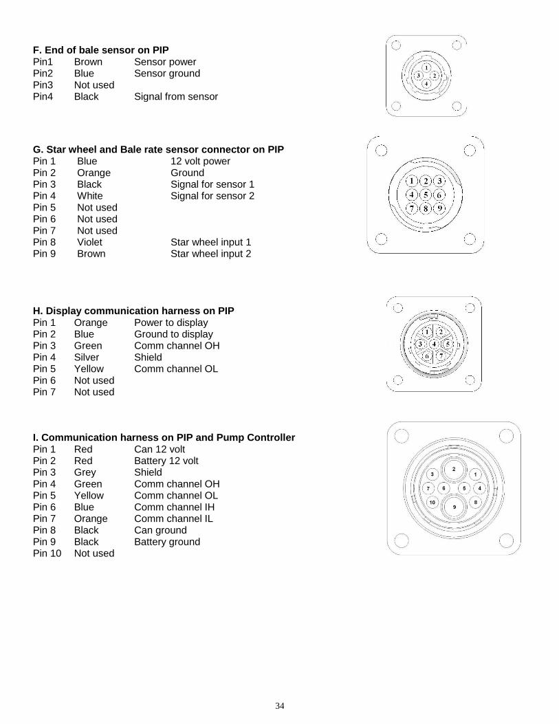
F. End of bale sensor on PIP Pin1 Brown Sensor power Pin2 Blue Sensor ground Pin3 Not used Pin4 Black Signal from sensor
G. Star wheel and Bale rate sensor connector on PIP Pin 1 Blue 12 volt power Pin 2 Orange Ground Pin 3 Black Signal for sensor 1 Pin 4 White Signal for sensor 2 Pin 5 Not used Pin 6 Not used Pin 7 Not used Pin 8 Violet Star wheel input 1 Pin 9 Brown Star wheel input 2
H. Display communication harness on PIP Pin 1 Orange Power to display Pin 2 Blue Ground to display Pin 3 Green Comm channel OH Pin 4 Silver Shield Pin 5 Yellow Comm channel OL Pin 6 Not used Pin 7 Not used
I. Communication harness on PIP and Pump Controller Pin 1 Red Can 12 volt Pin 2 Red Battery 12 volt Pin 3 Grey Shield Pin 4 Green Comm channel OH Pin 5 Yellow Comm channel OL Pin 6 Blue Comm channel IH Pin 7 Orange Comm channel IL Pin 8 Black Can ground Pin 9 Black Battery ground Pin 10 Not used
35
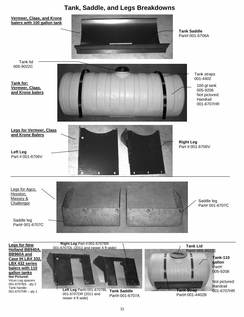
Tank, Saddle, and Legs Breakdowns
Tank Saddle Part#:001-6706A
Vermeer, Claas, and Krone balers with 100 gallon tank
Right Leg Part #:001-6706V
Legs for Vermeer, Claas and Krone Balers
Left Leg Part #:001-6706V
Tank-110 gallon Part#: 005-9208
Not pictured: Handrail 001-6707HR
Legs for New Holland BB940A, BB960A and Case IH LBX 332, LBX 432 series balers with 110 gallon tanks Not Pictured: Vicon Leg spacers 001-6707BS - qty 2 Tank handle: 001-6707HR – qty 1
Right Leg Part #:001-6707BR
001-6707DL (2011 and newer 4 ft wide)
Tank Lid Part#:005-9022E
Left Leg Part#:001-6707BL
001-6707DR (2011 and newer 4 ft wide)
Tank Saddle Part#:001-6707A
Tank Strap Part#:001-4402B
Legs for Agco, Hesston, Massey & Challenger
Saddle leg Part# 001-6707C
Saddle leg Part# 001-6707C
100-gl tank 005-9206 Not pictured: Handrail 001-6707HR
Tank straps 001-4402
Tank lid 005-9022C
Tank for: Vermeer, Claas, and Krone balers
36
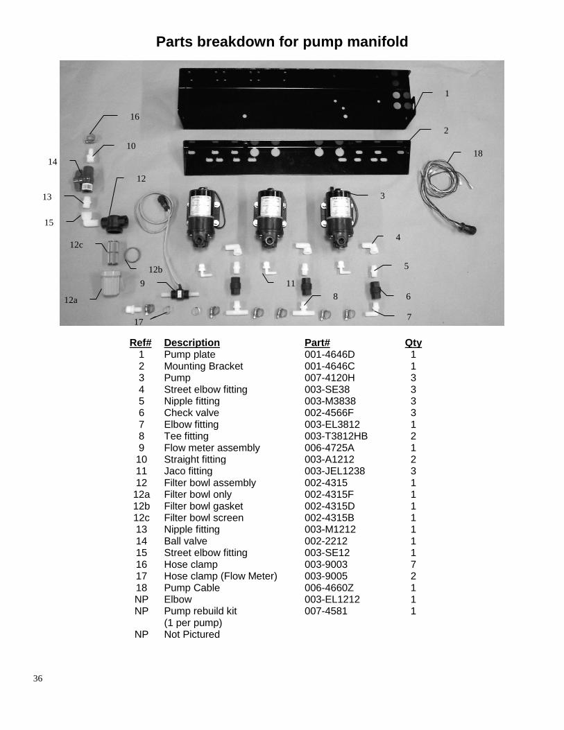
Parts breakdown for pump manifold
Ref# Description Part# Qty 1 Pump plate 001-4646D 1 2 Mounting Bracket 001-4646C 1 3 Pump 007-4120H 3 4 Street elbow fitting 003-SE38 3 5 Nipple fitting 003-M3838 3 6 Check valve 002-4566F 3 7 Elbow fitting 003-EL3812 1 8 Tee fitting 003-T3812HB 2 9 Flow meter assembly 006-4725A 1
10 Straight fitting 003-A1212 2 11 Jaco fitting 003-JEL1238 3 12 Filter bowl assembly 002-4315 1 12a Filter bowl only 002-4315F 1 12b Filter bowl gasket 002-4315D 1 12c Filter bowl screen 002-4315B 1 13 Nipple fitting 003-M1212 1 14 Ball valve 002-2212 1 15 Street elbow fitting 003-SE12 1 16 Hose clamp 003-9003 7 17 Hose clamp (Flow Meter) 003-9005 2 18 Pump Cable 006-4660Z 1 NP Elbow 003-EL1212 1 NP Pump rebuild kit
(1 per pump) 007-4581 1
NP Not Pictured
1
2
3
4
7
6
5
8
9
10
11
12
12a
12b
12c
13
14
15
16
17
18
37
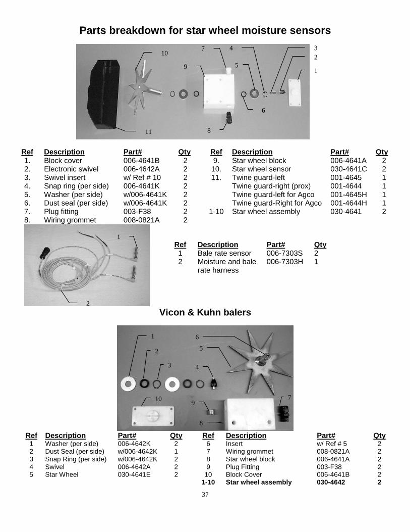
Parts breakdown for star wheel moisture sensors
Ref Description Part# Qty Ref Description Part# Qty 1. Block cover 006-4641B 2 9. Star wheel block 006-4641A 2 2. Electronic swivel 006-4642A 2 10. Star wheel sensor 030-4641C 2 3. Swivel insert w/ Ref # 10 2 11. Twine guard-left 001-4645 1 4. Snap ring (per side) 006-4641K 2 Twine guard-right (prox) 001-4644 1 5. Washer (per side) w/006-4641K 2 Twine guard-left for Agco 001-4645H 1 6. Dust seal (per side) w/006-4641K 2 Twine guard-Right for Agco 001-4644H 1 7. Plug fitting 003-F38 2 1-10 Star wheel assembly 030-4641 2 8. Wiring grommet 008-0821A 2
Vicon & Kuhn balers
Ref Description Part# Qty Ref Description Part# Qty
1 Washer (per side) 006-4642K 2 6 Insert w/ Ref # 5 2 2 Dust Seal (per side) w/006-4642K 1 7 Wiring grommet 008-0821A 2 3 Snap Ring (per side) w/006-4642K 2 8 Star wheel block 006-4641A 2 4 Swivel 006-4642A 2 9 Plug Fitting 003-F38 2 5 Star Wheel 030-4641E 2 10 Block Cover 006-4641B 2 1-10 Star wheel assembly 030-4642 2
Ref Description Part# Qty 1 Bale rate sensor 006-7303S 2 2 Moisture and bale
rate harness 006-7303H 1
1
2
4
5
6
7
8
9
10
11
3
1
2
3 4
5
6
7
8
9 10
2
1
38
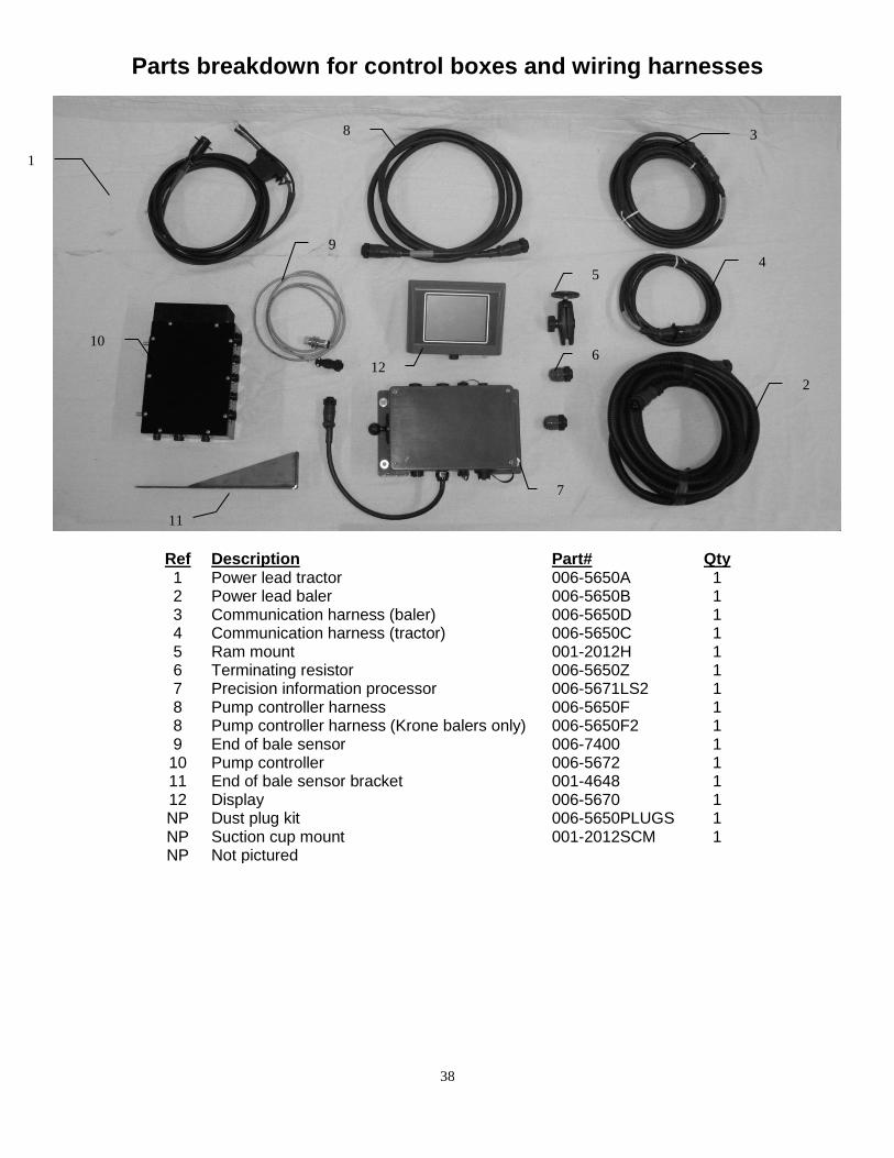
Parts breakdown for control boxes and wiring harnesses
Ref Description Part# Qty 1 Power lead tractor 006-5650A 1 2 Power lead baler 006-5650B 1 3 Communication harness (baler) 006-5650D 1 4 Communication harness (tractor) 006-5650C 1 5 Ram mount 001-2012H 1 6 Terminating resistor 006-5650Z 1 7 Precision information processor 006-5671LS2 1 8 Pump controller harness 006-5650F 1 8 Pump controller harness (Krone balers only) 006-5650F2 1 9 End of bale sensor 006-7400 1 10 Pump controller 006-5672 1 11 End of bale sensor bracket 001-4648 1 12 Display 006-5670 1 NP Dust plug kit 006-5650PLUGS 1 NP Suction cup mount 001-2012SCM 1 NP Not pictured
2
4 5
7
8
9
10
11
3
1
6 12
39
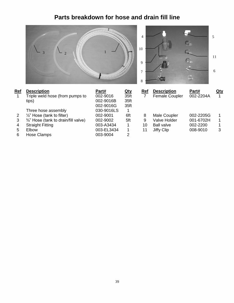
Parts breakdown for hose and drain fill line
Ref Description Part# Qty Ref Description Part# Qty 1 Triple weld hose (from pumps to
tips) Three hose assembly
002-9016 002-9016B 002-9016G 030-9016LS
35ft 35ft 35ft
1
7 Female Coupler 002-2204A 1
2 ½” Hose (tank to filter) 002-9001 6ft 8 Male Coupler 002-2205G 1 3 ¾” Hose (tank to drain/fill valve) 002-9002 5ft 9 Valve Holder 001-6702H 1 4 Straight Fitting 003-A3434 1 10 Ball valve 002-2200 1 5 Elbow 003-EL3434 1 11 Jiffy Clip 008-9010 3 6 Hose Clamps 003-9004 2
4 5
6 7
8
9
10
11
1 2 3
40
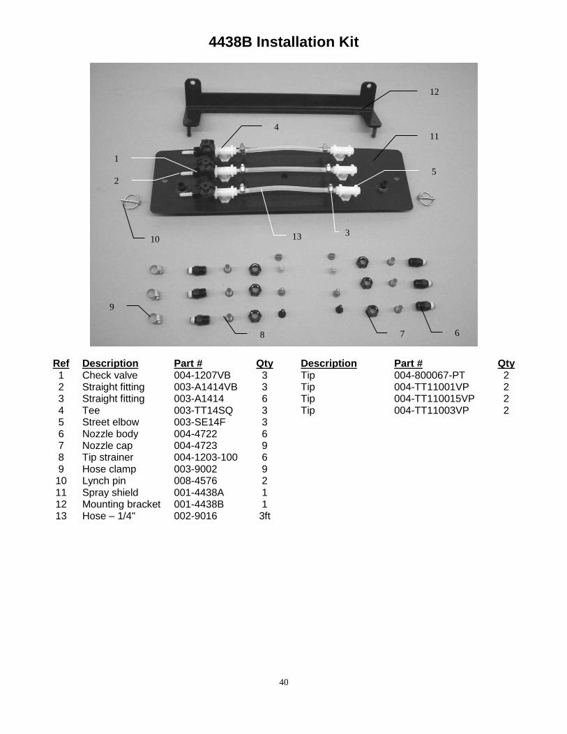
4438B Installation Kit
Ref Description Part # Qty Description Part # Qty 1 Check valve 004-1207VB 3 Tip 004-800067-PT 2 2 Straight fitting 003-A1414VB 3 Tip 004-TT11001VP 2 3 Straight fitting 003-A1414 6 Tip 004-TT110015VP 2 4 Tee 003-TT14SQ 3 Tip 004-TT11003VP 2 5 Street elbow 003-SE14F 3 6 Nozzle body 004-4722 6 7 Nozzle cap 004-4723 9 8 Tip strainer 004-1203-100 6 9 Hose clamp 003-9002 9
10 Lynch pin 008-4576 2 11 Spray shield 001-4438A 1 12 Mounting bracket 001-4438B 1 13 Hose – 1/4" 002-9016 3ft
1
2
3
5
6 7 8
9
10
11
12
13
4
41
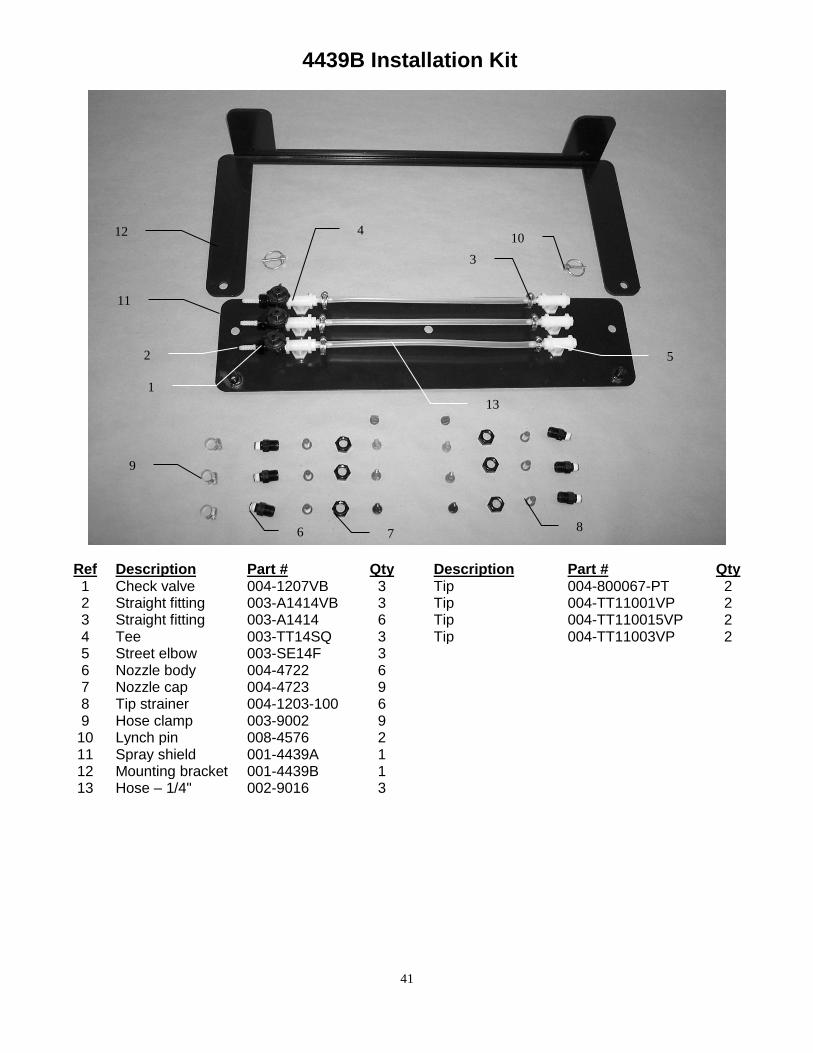
4439B Installation Kit
Ref Description Part # Qty Description Part # Qty 1 Check valve 004-1207VB 3 Tip 004-800067-PT 2 2 Straight fitting 003-A1414VB 3 Tip 004-TT11001VP 2 3 Straight fitting 003-A1414 6 Tip 004-TT110015VP 2 4 Tee 003-TT14SQ 3 Tip 004-TT11003VP 2 5 Street elbow 003-SE14F 3 6 Nozzle body 004-4722 6 7 Nozzle cap 004-4723 9 8 Tip strainer 004-1203-100 6 9 Hose clamp 003-9002 9
10 Lynch pin 008-4576 2 11 Spray shield 001-4439A 1 12 Mounting bracket 001-4439B 1 13 Hose – 1/4" 002-9016 3
1
2
3
4
5
6 7 8
9
10
11
12
13
42
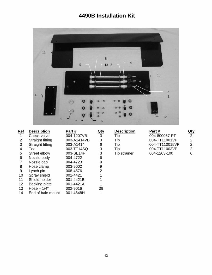
4490B Installation Kit
Ref Description Part # Qty Description Part # Qty 1 Check valve 004-1207VB 3 Tip 004-800067-PT 2 2 Straight fitting 003-A1414VB 3 Tip 004-TT11001VP 2 3 Straight fitting 003-A1414 6 Tip 004-TT110015VP 2 4 Tee 003-TT14SQ 3 Tip 004-TT11003VP 2 5 Street elbow 003-SE14F 3 Tip strainer 004-1203-100 6 6 Nozzle body 004-4722 6 7 Nozzle cap 004-4723 9 8 Hose clamp 003-9002 9 9 Lynch pin 008-4576 2
10 Spray shield 001-4421 1 11 Shield holder 001-4421B 1 12 Backing plate 001-4421A 1 13 Hose – 1/4" 002-9016 3ft 14 End of bale mount 001-4648H 1
1
2
3 4
5
6 7
8
9
10
11
12
13
14
43
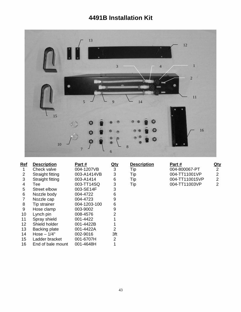
4491B Installation Kit
Ref Description Part # Qty Description Part # Qty 1 Check valve 004-1207VB 3 Tip 004-800067-PT 2 2 Straight fitting 003-A1414VB 3 Tip 004-TT11001VP 2 3 Straight fitting 003-A1414 6 Tip 004-TT110015VP 2 4 Tee 003-TT14SQ 3 Tip 004-TT11003VP 2 5 Street elbow 003-SE14F 3 6 Nozzle body 004-4722 6 7 Nozzle cap 004-4723 9 8 Tip strainer 004-1203-100 6 9 Hose clamp 003-9002 9
10 Lynch pin 008-4576 2 11 Spray shield 001-4422 1 12 Shield holder 001-4422B 1 13 Backing plate 001-4422A 2 14 Hose – 1/4" 002-9016 3ft 15 Ladder bracket 001-6707H 2 16 End of bale mount 001-4648H 1
1
2
3 4
5
6 7
8
9
10
11
12
13
14
15
16
44
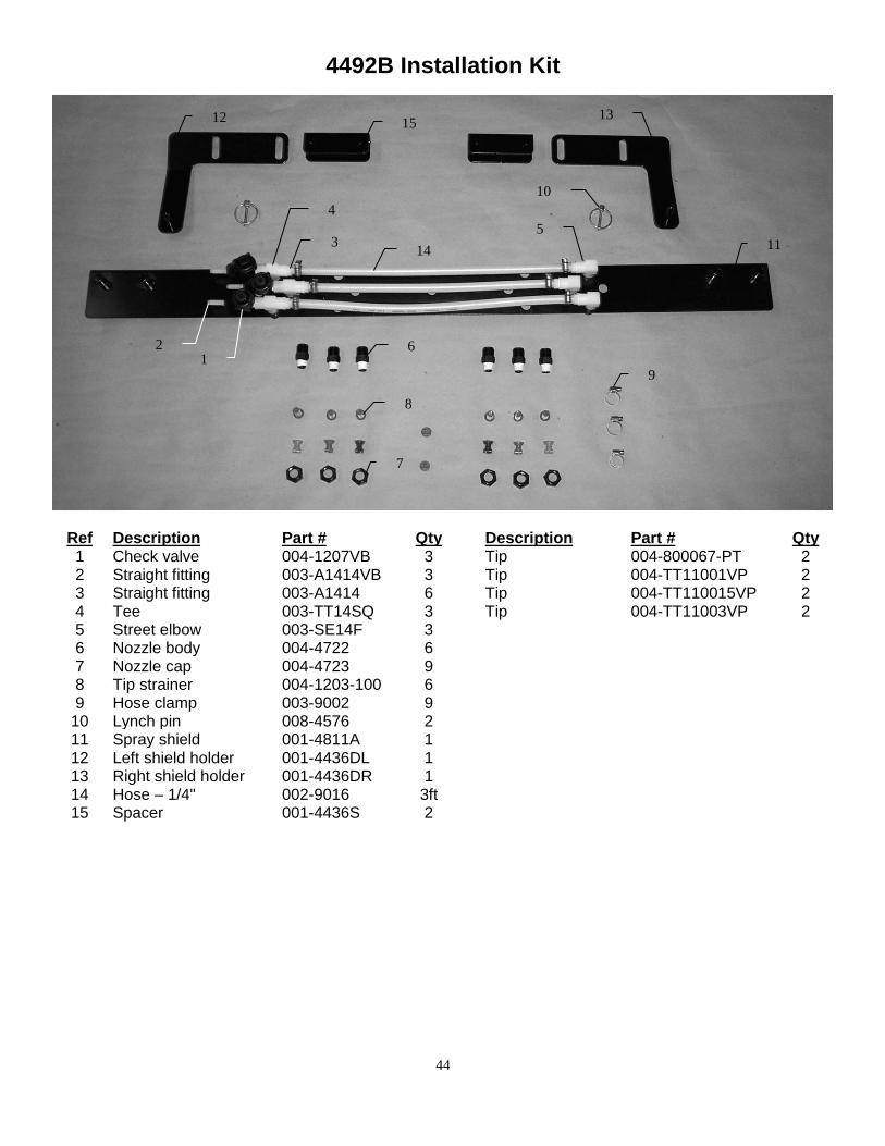
4492B Installation Kit
Ref Description Part # Qty Description Part # Qty 1 Check valve 004-1207VB 3 Tip 004-800067-PT 2 2 Straight fitting 003-A1414VB 3 Tip 004-TT11001VP 2 3 Straight fitting 003-A1414 6 Tip 004-TT110015VP 2 4 Tee 003-TT14SQ 3 Tip 004-TT11003VP 2 5 Street elbow 003-SE14F 3 6 Nozzle body 004-4722 6 7 Nozzle cap 004-4723 9 8 Tip strainer 004-1203-100 6 9 Hose clamp 003-9002 9
10 Lynch pin 008-4576 2 11 Spray shield 001-4811A 1 12 Left shield holder 001-4436DL 1 13 Right shield holder 001-4436DR 1 14 Hose – 1/4" 002-9016 3ft 15 Spacer 001-4436S 2
1 2
3
4
5
6
7
8
9
10
11
12 13
14
15
45
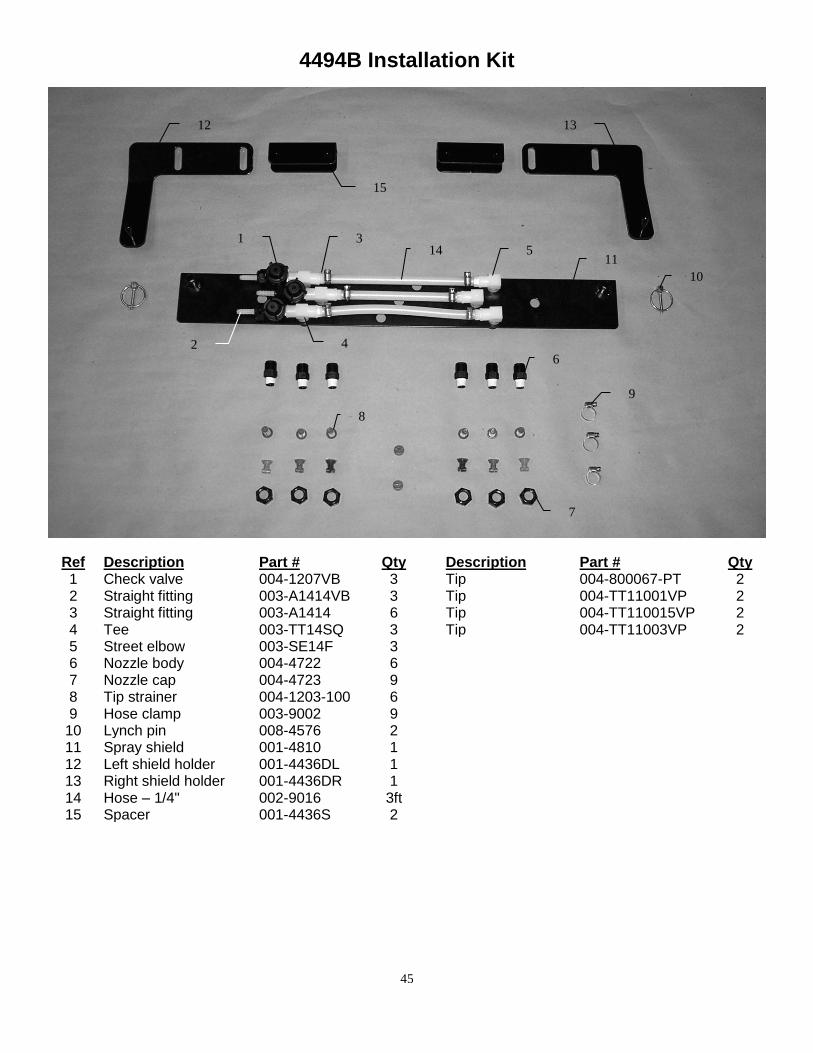
4494B Installation Kit
Ref Description Part # Qty Description Part # Qty 1 Check valve 004-1207VB 3 Tip 004-800067-PT 2 2 Straight fitting 003-A1414VB 3 Tip 004-TT11001VP 2 3 Straight fitting 003-A1414 6 Tip 004-TT110015VP 2 4 Tee 003-TT14SQ 3 Tip 004-TT11003VP 2 5 Street elbow 003-SE14F 3 6 Nozzle body 004-4722 6 7 Nozzle cap 004-4723 9 8 Tip strainer 004-1203-100 6 9 Hose clamp 003-9002 9
10 Lynch pin 008-4576 2 11 Spray shield 001-4810 1 12 Left shield holder 001-4436DL 1 13 Right shield holder 001-4436DR 1 14 Hose – 1/4" 002-9016 3ft 15 Spacer 001-4436S 2
1
2
3
4
5
6
7
8
9
10
11
12 13
14
15

46
4495B & 4528B Installation Kit
Ref Description Part# Qty Description Part# Qty 1 Check valve 004-1207VB 3 Tip 004-800067-PT 2 2 Straight fitting 003-A1414VB 3 Tip 004-TT11001VP 2 3 Straight fitting 003-A1414 6 Tip 004-TT110015VP 2 4 Tee 003-TT14SQ 3 Tip 004-TT11003VP 2 5 Street elbow 003-SE14F 3 6 Nozzle body 004-4722 6 7 Nozzle cap 004-4723 9 8 Tip strainer 004-1203-100 6 9 Hose clamp 003-9002 9
10 Lynch pin 008-4576 2 11 Spray shield 001-4431 1 12 Shield holder 001-4431B 1 13 Hose – 1/4" 002-9016 3ft 14 Wind guard stop 001-4431D 2
1
2
3
4
5
6
7
8
9
10
11
12 13
14
47
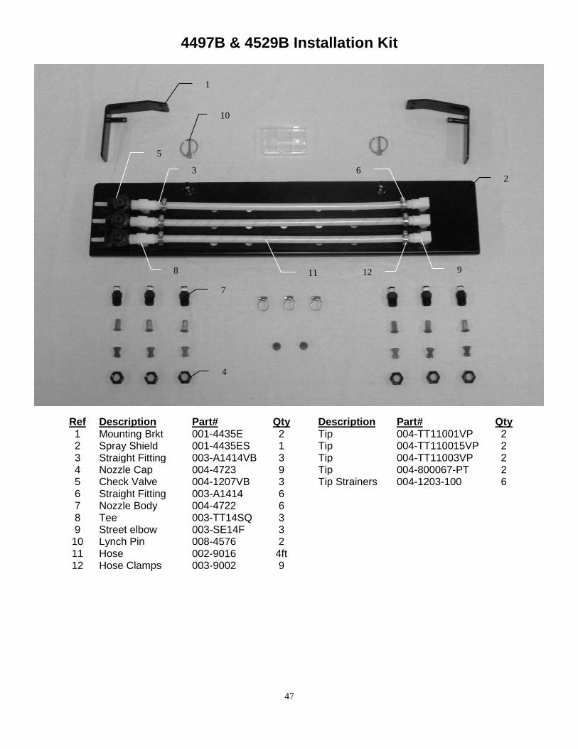
4497B & 4529B Installation Kit
Ref Description Part# Qty Description Part# Qty 1 Mounting Brkt 001-4435E 2 Tip 004-TT11001VP 2 2 Spray Shield 001-4435ES 1 Tip 004-TT110015VP 2 3 Straight Fitting 003-A1414VB 3 Tip 004-TT11003VP 2 4 Nozzle Cap 004-4723 9 Tip 004-800067-PT 2 5 Check Valve 004-1207VB 3 Tip Strainers 004-1203-100 6 6 Straight Fitting 003-A1414 6 7 Nozzle Body 004-4722 6 8 Tee 003-TT14SQ 3 9 Street elbow 003-SE14F 3
10 Lynch Pin 008-4576 2 11 Hose 002-9016 4ft 12 Hose Clamps 003-9002 9
1
2 3
4
5
6
7
8 9
10
11 12
48
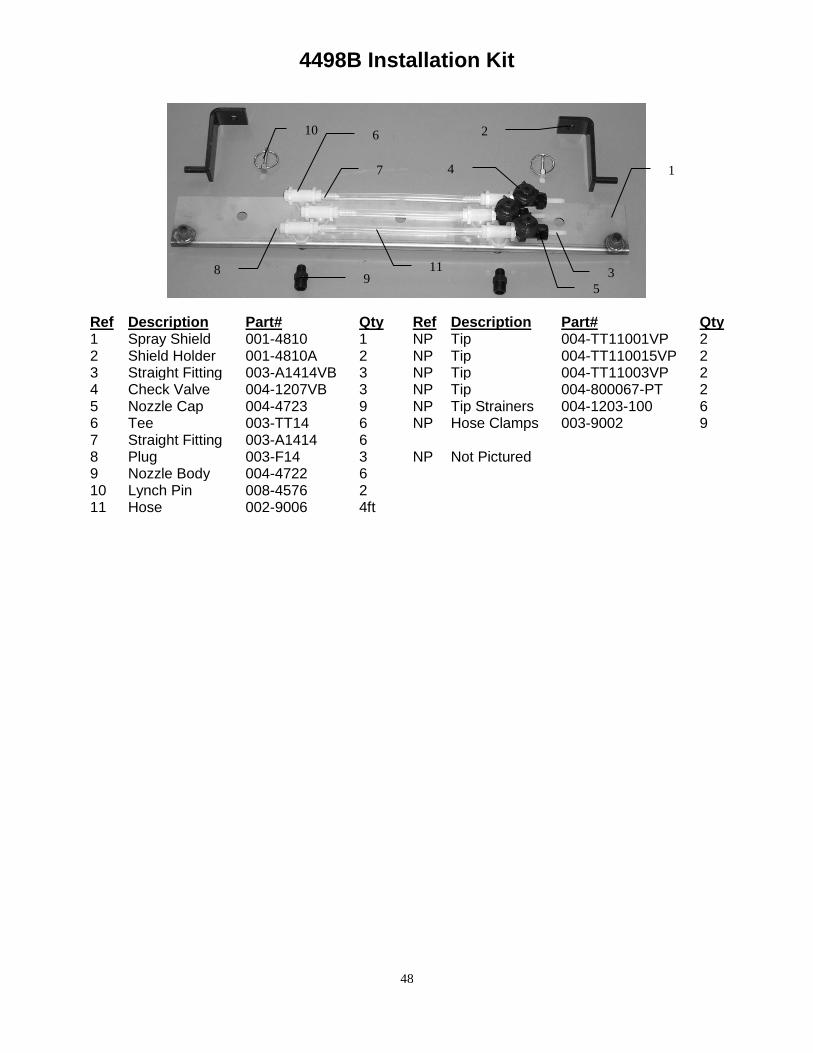
4498B Installation Kit
Ref Description Part# Qty Ref Description Part# Qty 1 Spray Shield 001-4810 1 NP Tip 004-TT11001VP 2 2 Shield Holder 001-4810A 2 NP Tip 004-TT110015VP 2 3 Straight Fitting 003-A1414VB 3 NP Tip 004-TT11003VP 2 4 Check Valve 004-1207VB 3 NP Tip 004-800067-PT 2 5 Nozzle Cap 004-4723 9 NP Tip Strainers 004-1203-100 6 6 Tee 003-TT14 6 NP Hose Clamps 003-9002 9 7 Straight Fitting 003-A1414 6 8 Plug 003-F14 3 NP Not Pictured 9 Nozzle Body 004-4722 6 10 Lynch Pin 008-4576 2 11 Hose 002-9006 4ft
1
2
3
4
5
6
7
8 9
10
11
49
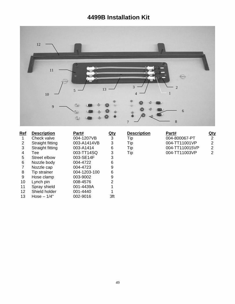
4499B Installation Kit
Ref Description Part# Qty Description Part# Qty 1 Check valve 004-1207VB 3 Tip 004-800067-PT 2 2 Straight fitting 003-A1414VB 3 Tip 004-TT11001VP 2 3 Straight fitting 003-A1414 6 Tip 004-TT110015VP 2 4 Tee 003-TT14SQ 3 Tip 004-TT11003VP 2 5 Street elbow 003-SE14F 3 6 Nozzle body 004-4722 6 7 Nozzle cap 004-4723 9 8 Tip strainer 004-1203-100 6 9 Hose clamp 003-9002 9
10 Lynch pin 008-4576 2 11 Spray shield 001-4439A 1 12 Shield holder 001-4440 1 13 Hose – 1/4" 002-9016 3ft
1
2 3
4 5
6
7 8
9
10
11
12
13
50
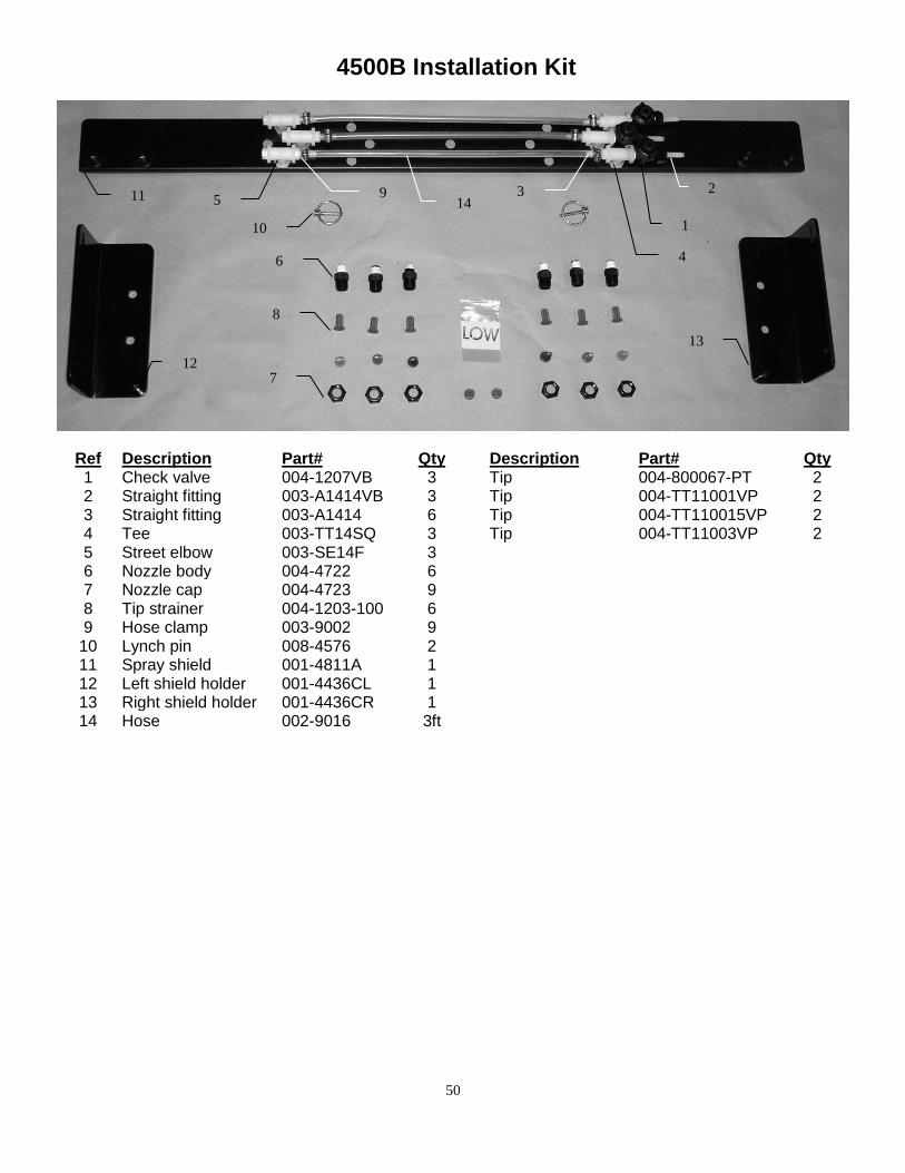
4500B Installation Kit
Ref Description Part# Qty Description Part# Qty 1 Check valve 004-1207VB 3 Tip 004-800067-PT 2 2 Straight fitting 003-A1414VB 3 Tip 004-TT11001VP 2 3 Straight fitting 003-A1414 6 Tip 004-TT110015VP 2 4 Tee 003-TT14SQ 3 Tip 004-TT11003VP 2 5 Street elbow 003-SE14F 3 6 Nozzle body 004-4722 6 7 Nozzle cap 004-4723 9 8 Tip strainer 004-1203-100 6 9 Hose clamp 003-9002 9
10 Lynch pin 008-4576 2 11 Spray shield 001-4811A 1 12 Left shield holder 001-4436CL 1 13 Right shield holder 001-4436CR 1 14 Hose 002-9016 3ft
1
2 3
4
5
6
7
8
9
10
11
12
13
14
51
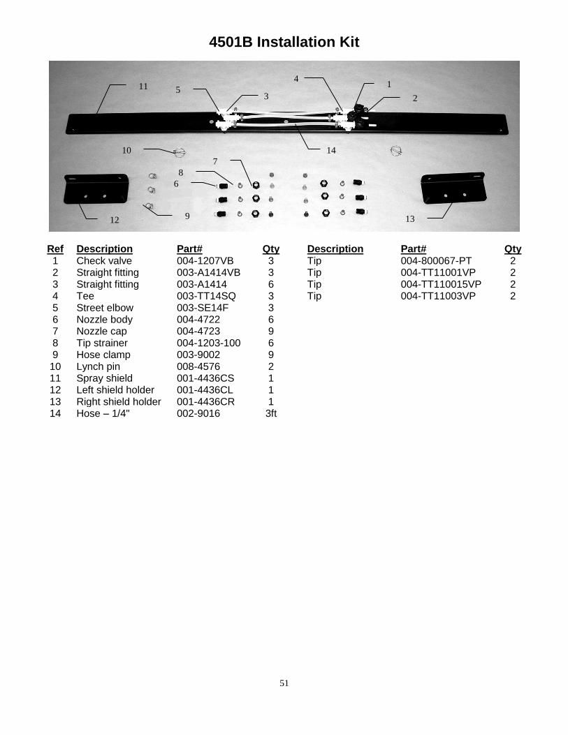
4501B Installation Kit
Ref Description Part# Qty Description Part# Qty 1 Check valve 004-1207VB 3 Tip 004-800067-PT 2 2 Straight fitting 003-A1414VB 3 Tip 004-TT11001VP 2 3 Straight fitting 003-A1414 6 Tip 004-TT110015VP 2 4 Tee 003-TT14SQ 3 Tip 004-TT11003VP 2 5 Street elbow 003-SE14F 3 6 Nozzle body 004-4722 6 7 Nozzle cap 004-4723 9 8 Tip strainer 004-1203-100 6 9 Hose clamp 003-9002 9
10 Lynch pin 008-4576 2 11 Spray shield 001-4436CS 1 12 Left shield holder 001-4436CL 1 13 Right shield holder 001-4436CR 1 14 Hose – 1/4" 002-9016 3ft
1
2 3
4
5
6
7
8
9
10
12 13
11
14
52
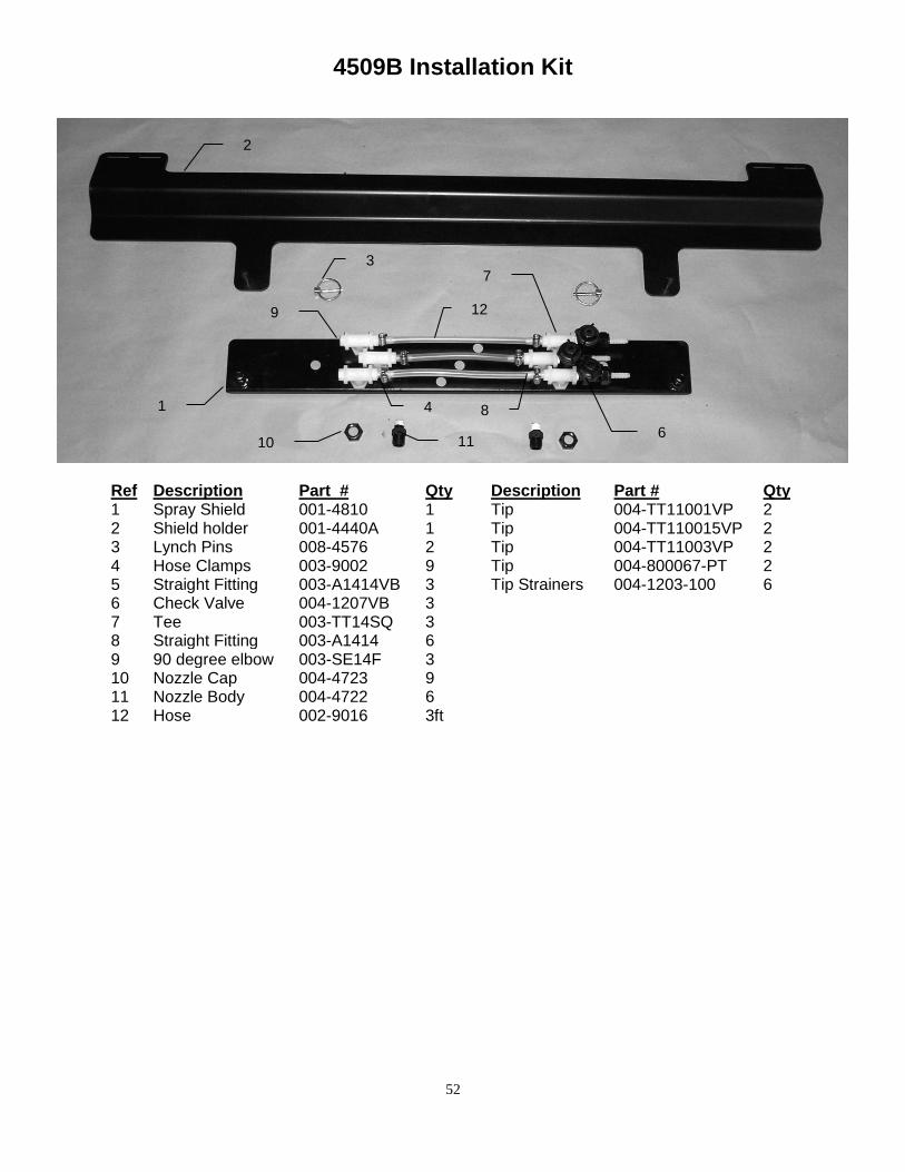
4509B Installation Kit
Ref Description Part # Qty Description Part # Qty 1 Spray Shield 001-4810 1 Tip 004-TT11001VP 2 2 Shield holder 001-4440A 1 Tip 004-TT110015VP 2 3 Lynch Pins 008-4576 2 Tip 004-TT11003VP 2 4 Hose Clamps 003-9002 9 Tip 004-800067-PT 2 5 Straight Fitting 003-A1414VB 3 Tip Strainers 004-1203-100 6 6 Check Valve 004-1207VB 3 7 Tee 003-TT14SQ 3 8 Straight Fitting 003-A1414 6 9 90 degree elbow 003-SE14F 3 10 Nozzle Cap 004-4723 9 11 Nozzle Body 004-4722 6 12 Hose 002-9016 3ft
1
2
3
4 8
6
9
11 10
12
7
53
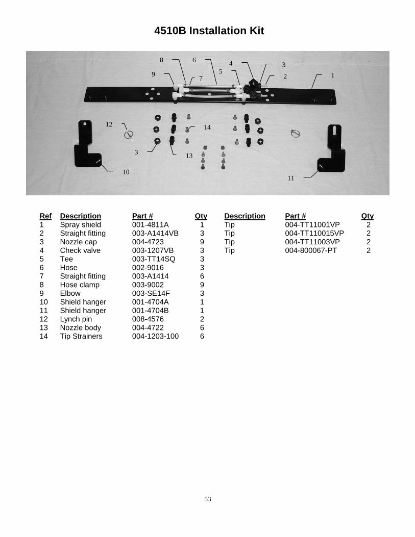
4510B Installation Kit
Ref Description Part # Qty Description Part # Qty 1 Spray shield 001-4811A 1 Tip 004-TT11001VP 2 2 Straight fitting 003-A1414VB 3 Tip 004-TT110015VP 2 3 Nozzle cap 004-4723 9 Tip 004-TT11003VP 2 4 Check valve 003-1207VB 3 Tip 004-800067-PT 2 5 Tee 003-TT14SQ 3 6 Hose 002-9016 3 7 Straight fitting 003-A1414 6 8 Hose clamp 003-9002 9 9 Elbow 003-SE14F 3 10 Shield hanger 001-4704A 1 11 Shield hanger 001-4704B 1 12 Lynch pin 008-4576 2 13 Nozzle body 004-4722 6 14 Tip Strainers 004-1203-100 6
1 2
3 4
5
6
7
8
9
10
12
3 13
11
14
54
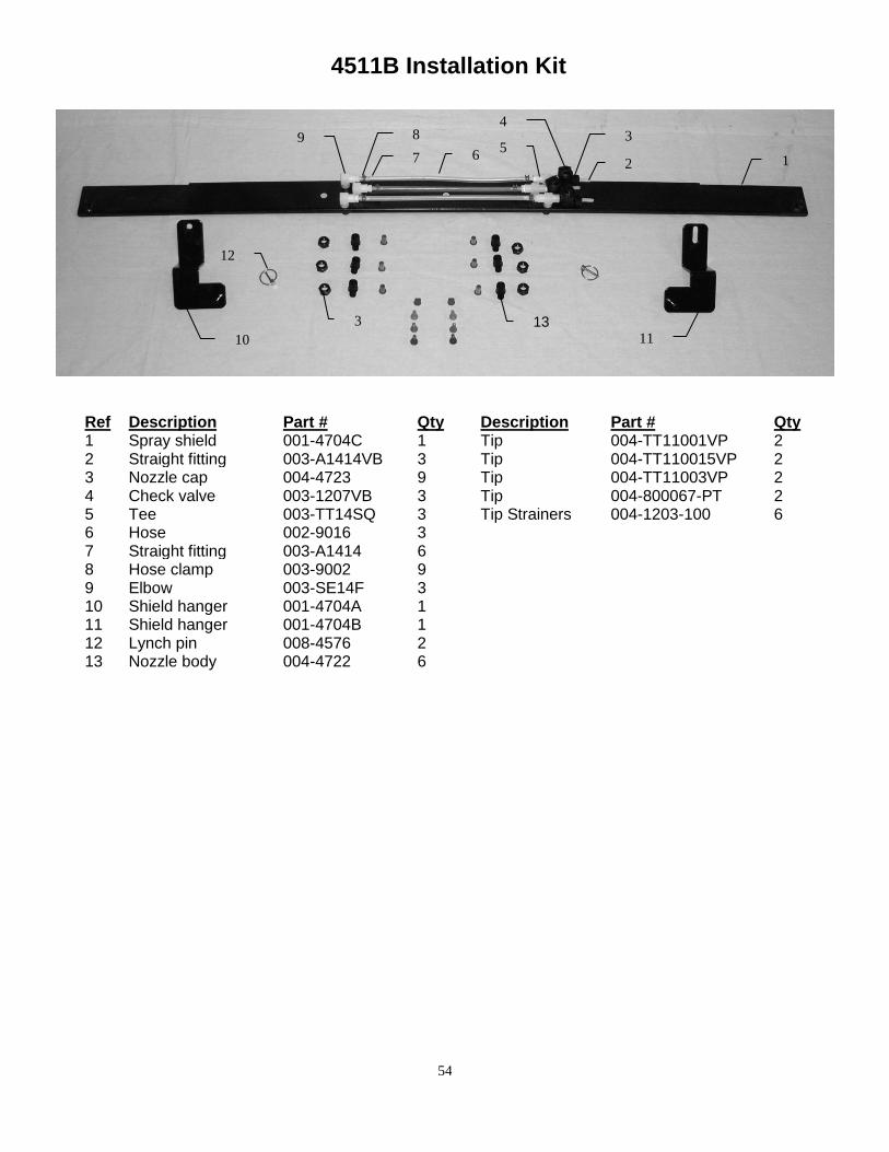
4511B Installation Kit
Ref Description Part # Qty Description Part # Qty 1 Spray shield 001-4704C 1 Tip 004-TT11001VP 2 2 Straight fitting 003-A1414VB 3 Tip 004-TT110015VP 2 3 Nozzle cap 004-4723 9 Tip 004-TT11003VP 2 4 Check valve 003-1207VB 3 Tip 004-800067-PT 2 5 Tee 003-TT14SQ 3 Tip Strainers 004-1203-100 6 6 Hose 002-9016 3 7 Straight fitting 003-A1414 6 8 Hose clamp 003-9002 9 9 Elbow 003-SE14F 3 10 Shield hanger 001-4704A 1 11 Shield hanger 001-4704B 1 12 Lynch pin 008-4576 2 13 Nozzle body 004-4722 6
1 2
3 4
5 6 7
8 9
10 11
12
3 13
55
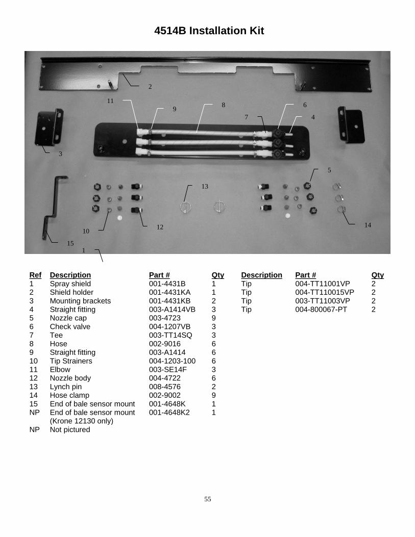
4514B Installation Kit
Ref Description Part # Qty Description Part # Qty 1 Spray shield 001-4431B 1 Tip 004-TT11001VP 2 2 Shield holder 001-4431KA 1 Tip 004-TT110015VP 2 3 Mounting brackets 001-4431KB 2 Tip 003-TT11003VP 2 4 Straight fitting 003-A1414VB 3 Tip 004-800067-PT 2 5 Nozzle cap 003-4723 9 6 Check valve 004-1207VB 3 7 Tee 003-TT14SQ 3 8 Hose 002-9016 6 9 Straight fitting 003-A1414 6 10 Tip Strainers 004-1203-100 6 11 Elbow 003-SE14F 3 12 Nozzle body 004-4722 6 13 Lynch pin 008-4576 2 14 Hose clamp 002-9002 9 15 End of bale sensor mount 001-4648K 1 NP End of bale sensor mount
(Krone 12130 only) 001-4648K2 1
NP Not pictured
1
3
2
4
5
6
7
8 9
10
11
12
13
14
15
56
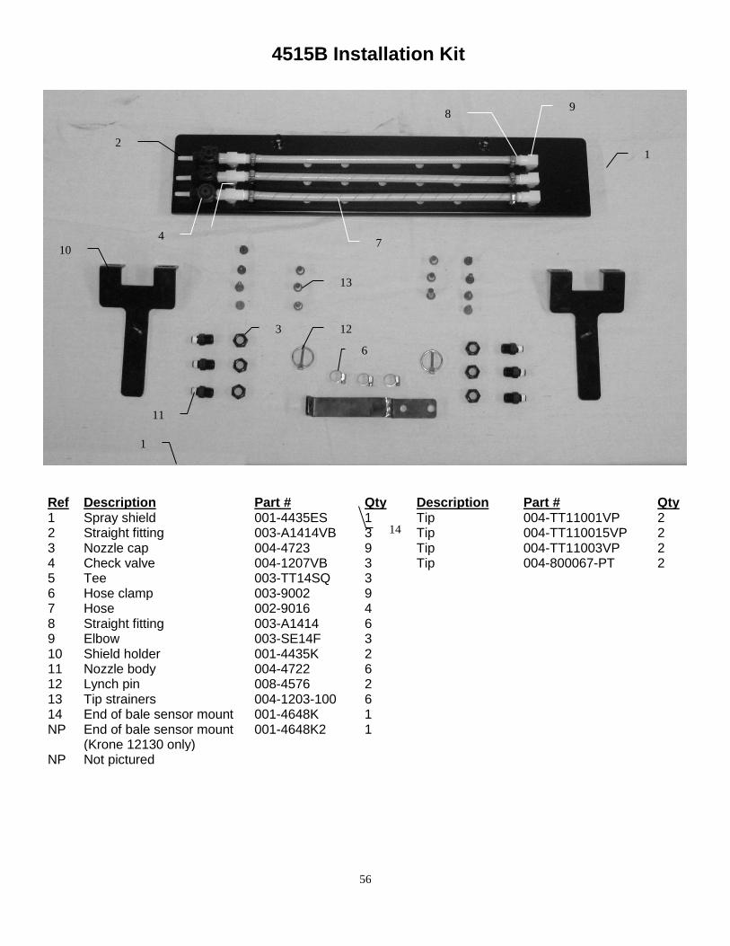
4515B Installation Kit
Ref Description Part # Qty Description Part # Qty 1 Spray shield 001-4435ES 1 Tip 004-TT11001VP 2 2 Straight fitting 003-A1414VB 3 Tip 004-TT110015VP 2 3 Nozzle cap 004-4723 9 Tip 004-TT11003VP 2 4 Check valve 004-1207VB 3 Tip 004-800067-PT 2 5 Tee 003-TT14SQ 3 6 Hose clamp 003-9002 9 7 Hose 002-9016 4 8 Straight fitting 003-A1414 6 9 Elbow 003-SE14F 3 10 Shield holder 001-4435K 2 11 Nozzle body 004-4722 6 12 Lynch pin 008-4576 2 13 Tip strainers 004-1203-100 6 14 End of bale sensor mount 001-4648K 1 NP End of bale sensor mount
(Krone 12130 only) 001-4648K2 1
NP Not pictured
1 2
3
4
5
6
7
8 9
10
11
12
13
14
1
57
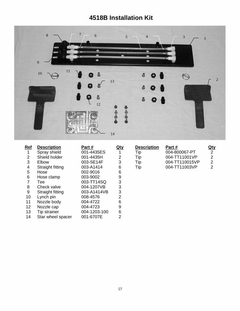
4518B Installation Kit
Ref Description Part # Qty Description Part # Qty 1 Spray shield 001-4435ES 1 Tip 004-800067-PT 2 2 Shield holder 001-4435H 2 Tip 004-TT11001VP 2 3 Elbow 003-SE14F 3 Tip 004-TT110015VP 2 4 Straight fitting 003-A1414 6 Tip 004-TT11003VP 2 5 Hose 002-9016 6 6 Hose clamp 003-9002 9 7 Tee 003-TT14SQ 3 8 Check valve 004-1207VB 3 9 Straight fitting 003-A1414VB 3
10 Lynch pin 008-4576 2 11 Nozzle body 004-4722 6 12 Nozzle cap 004-4723 9 13 Tip strainer 004-1203-100 6 14 Star wheel spacer 001-6707E 2
1
2
3 4 5 6 7 8
9
10 11
12
13
14
58
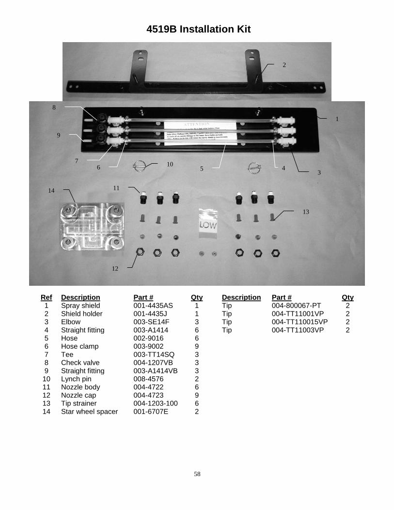
4519B Installation Kit
Ref Description Part # Qty Description Part # Qty 1 Spray shield 001-4435AS 1 Tip 004-800067-PT 2 2 Shield holder 001-4435J 1 Tip 004-TT11001VP 2 3 Elbow 003-SE14F 3 Tip 004-TT110015VP 2 4 Straight fitting 003-A1414 6 Tip 004-TT11003VP 2 5 Hose 002-9016 6 6 Hose clamp 003-9002 9 7 Tee 003-TT14SQ 3 8 Check valve 004-1207VB 3 9 Straight fitting 003-A1414VB 3
10 Lynch pin 008-4576 2 11 Nozzle body 004-4722 6 12 Nozzle cap 004-4723 9 13 Tip strainer 004-1203-100 6 14 Star wheel spacer 001-6707E 2
1
2
3 4 5 6
7
8
9
10
11
12
13
14
59
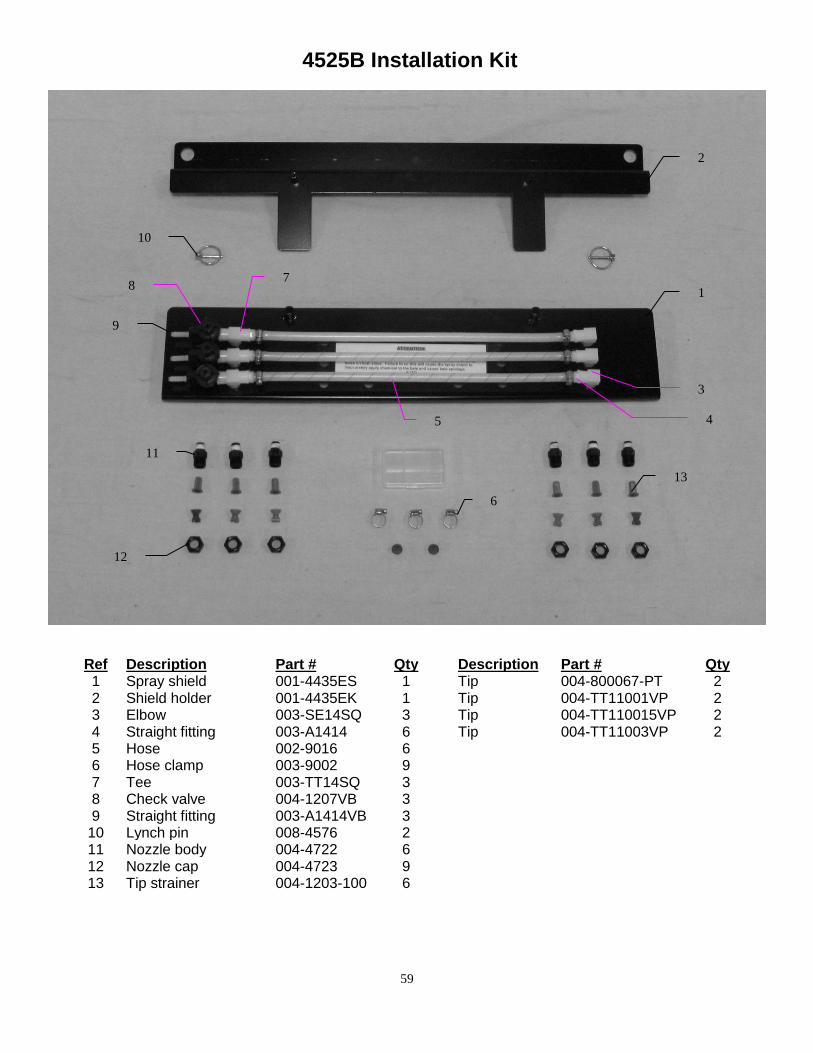
4525B Installation Kit
Ref Description Part # Qty Description Part # Qty 1 Spray shield 001-4435ES 1 Tip 004-800067-PT 2 2 Shield holder 001-4435EK 1 Tip 004-TT11001VP 2 3 Elbow 003-SE14SQ 3 Tip 004-TT110015VP 2 4 Straight fitting 003-A1414 6 Tip 004-TT11003VP 2 5 Hose 002-9016 6 6 Hose clamp 003-9002 9 7 Tee 003-TT14SQ 3 8 Check valve 004-1207VB 3 9 Straight fitting 003-A1414VB 3
10 Lynch pin 008-4576 2 11 Nozzle body 004-4722 6 12 Nozzle cap 004-4723 9 13 Tip strainer 004-1203-100 6
1
2
3
4 5
6
7 8
9
10
11
12
13
60
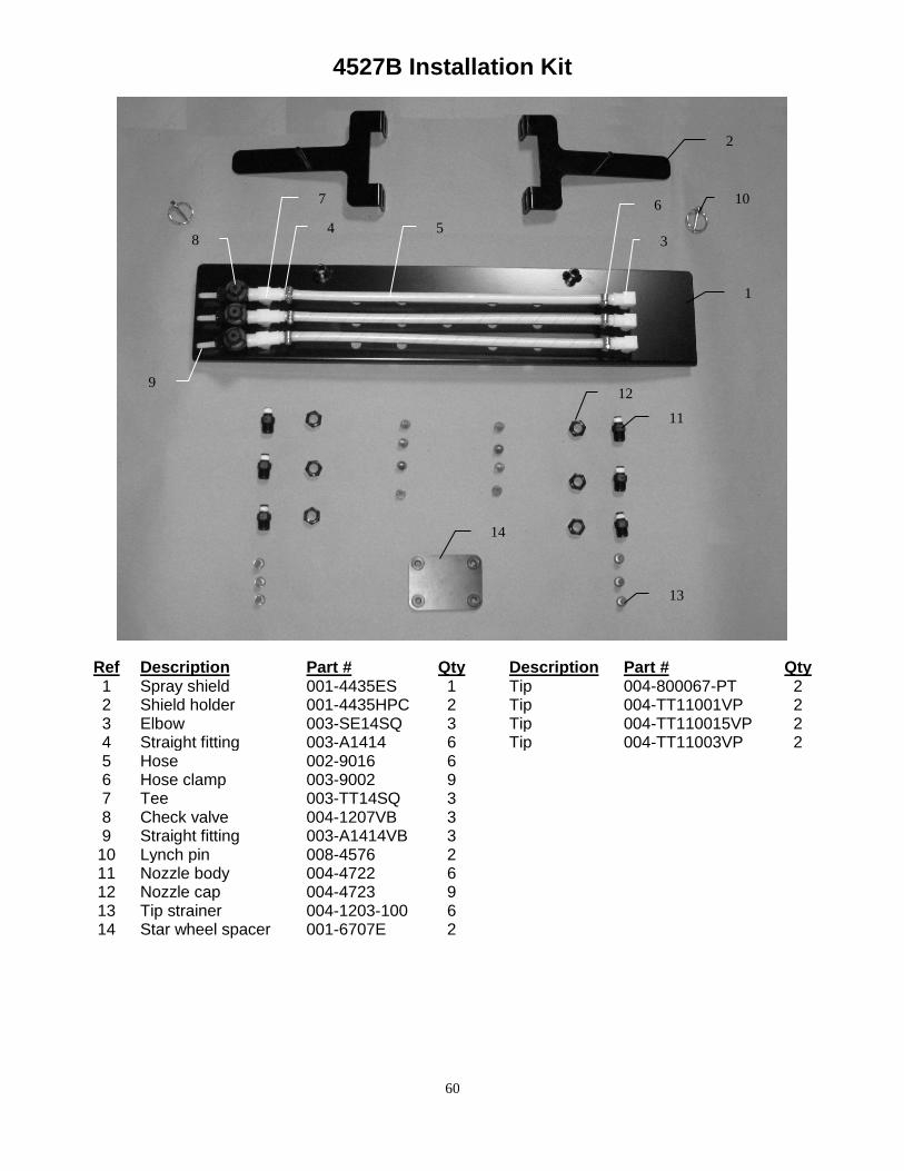
4527B Installation Kit
Ref Description Part # Qty Description Part # Qty 1 Spray shield 001-4435ES 1 Tip 004-800067-PT 2 2 Shield holder 001-4435HPC 2 Tip 004-TT11001VP 2 3 Elbow 003-SE14SQ 3 Tip 004-TT110015VP 2 4 Straight fitting 003-A1414 6 Tip 004-TT11003VP 2 5 Hose 002-9016 6 6 Hose clamp 003-9002 9 7 Tee 003-TT14SQ 3 8 Check valve 004-1207VB 3 9 Straight fitting 003-A1414VB 3
10 Lynch pin 008-4576 2 11 Nozzle body 004-4722 6 12 Nozzle cap 004-4723 9 13 Tip strainer 004-1203-100 6 14 Star wheel spacer 001-6707E 2
1
2
3 4 5
6 7
8
9
10
11
12
13
14
61
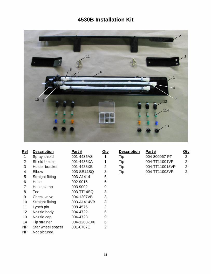
4530B Installation Kit
Ref Description Part # Qty Description Part # Qty
1 Spray shield 001-4435AS 1 Tip 004-800067-PT 2
2 Shield holder 001-4435XA 1 Tip 004-TT11001VP 2
3 Holder bracket 001-4435XB 2 Tip 004-TT110015VP 2
4 Elbow 003-SE14SQ 3 Tip 004-TT11003VP 2
5 Straight fitting 003-A1414 6
6 Hose 002-9016 6
7 Hose clamp 003-9002 9
8 Tee 003-TT14SQ 3
9 Check valve 004-1207VB 3
10 Straight fitting 003-A1414VB 3
11 Lynch pin 008-4576 2
12 Nozzle body 004-4722 6
13 Nozzle cap 004-4723 9
14 Tip strainer 004-1203-100 6
NP Star wheel spacer 001-6707E 2
NP Not pictured
1
2
3
4
5
6 7 8
9 10
13
11
12
114
62
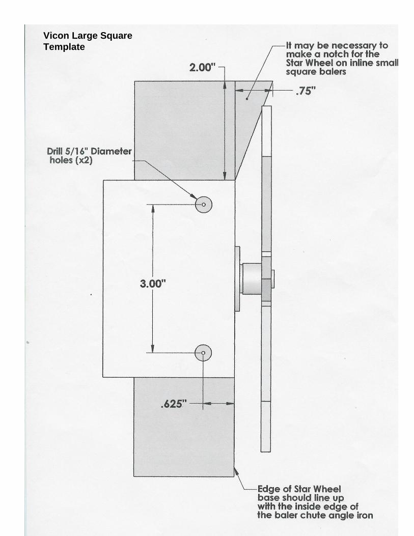
Vicon Large Square
Template
63
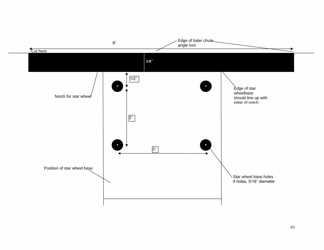
9”
5/8”
Star wheel base holes 4 holes, 5/16” diameter
3”
1/2”
2”
Notch for star wheel
Position of star wheel base
Edge of star wheelbase should line up with edge of notch
Edge of baler chute angle iron
Cut here angle iron

64
NOTES:

65
WARRANTY AND LIABILITY AGREEMENT
Harvest Tec, Inc. will repair or replace components that are found to be defective within 12 months from the date of manufacture. Under no circumstances does this warranty cover any components which in the opinion of Harvest Tec, Inc. have been subjected to negligent use, misuse, alteration, accident, or if repairs have been made with parts other than those manufactured and obtainable from Harvest Tec, Inc. Our obligation under this warranty is limited to repairing or replacing free of charge to the original purchaser any part that in our judgment shows evidence of defective or improper workmanship, provided the part is returned to Harvest Tec, Inc. within 30 days of the failure. Parts must be returned through the selling dealer and distributor, transportation charges prepaid. This warranty shall not be interpreted to render Harvest Tec, Inc. liable for injury or damages of any kind, direct, consequential, or contingent, to persons or property. Furthermore, this warranty does not extend to loss of crop, losses caused by delays or any expense prospective profits or for any other reason. Harvest Tec, Inc. shall not be liable for any recovery greater in amount than the cost or repair of defects in workmanship. There are no warranties, either expressed or implied, of merchantability or fitness for particular purpose intended or fitness for any other reason. This warranty cannot guarantee that existing conditions beyond the control of Harvest Tec, Inc. will not affect our ability to obtain materials or manufacture necessary replacement parts. Harvest Tec, Inc. reserves the right to make design changes, improve design, or change specifications, at any time without any contingent obligation to purchasers of machines and parts previously sold. Revised 01/03/06

66
HARVEST TEC, INC. P.O. BOX 63
2821 HARVEY STREET HUDSON, WI 54016
PHONE: 715-386-9100 1-800-635-7468
FAX: 715-381-1792 Email: [email protected]