operation manual - test & measurement … · operation manual dakota ultrasonics cmmxxdll++...
TRANSCRIPT

OPERATION MANUAL
DAKOTA ULTRASONICS
CCMMXXDDLL++ Material & Coating Thickness Gauge
P/N P-172-0002 Rev 2.06, July 2010


CHAPTER ONE INTRODUCTION .......................................................................1
CHAPTER TWO QUICK STARTUP GUIDE ........................................................2
CHAPTER THREE KEYBOARD, MENU, & CONNECTOR REFERENCE.......24
CHAPTER FOUR PRINCIPALS OF ULTRASONIC MEASUREMENT .............36
CHAPTER FIVE SELECTING THE MEASUREMENT MODE ..........................41
CHAPTER SIX MAKING MEASUREMENTS.....................................................44
CHAPTER SEVEN USING THE DISPLAY OPTIONS .......................................60
CHAPTER EIGHT THRU PAINT MEASUREMENT TECHNIQUE ....................91
CHAPTER NINE PULSE-ECHO COATING & COATING TECHNIQUES.........94
CHAPTER TEN ADDITIONAL FEATURES OF THE CMXDL+ .........................109
CHAPTER ELEVEN DATA STORAGE – SETUP, EDIT, & VIEW FILES .......131
CHAPTER TWELVE SETUPS – CREATE, STORE, EDIT, & RECALL..........157
CHAPTER THIRTEEN USING THE UTILITY SOFTWARE.............................167
APPENDIX A - VELOCITY TABLE...................................................................169
APPENDIX B - SETUP LIBRARY.....................................................................171


CHAPTER ONE INTRODUCTION
The Dakota Ultrasonics model CMXDL+ is an ultrasonic thickness gauge that measures with extreme versatility. It has the ability to measure simultaneously measure coatings and material thicknesses while maintaining the ability to locate pits, flaws and defects in the material. Based on the same operating principles as SONAR, the CMXDL+ is capable of measuring the thickness of various materials with accuracy as high as ± 0.001 inches, or ± 0.01 millimeters. The principle advantage of ultrasonic measurement over traditional methods is that ultrasonic measurements can be performed with access to only one side of the material being measured. Dakota Ultrasonics maintains a customer support resource in order to assist users with questions or difficulties not covered in this manual. Customer support may be reached at any of the following:
• Dakota Ultrasonics Corporation, 1500 Green Hills Road, #107 Scotts Valley, CA 95066 USA
• Telephone: (831) 431-9722 • Facsimile: (831) 431-9723 • http://www.dakotaultrasonics.com
1.1 Disclaimer Inherent in ultrasonic thickness measurement is the possibility that the instrument will use the second rather than the first echo from the back surface of the material being measured. This may result in a thickness reading that is TWICE what it should be. Responsibility for proper use of the instrument and recognition of this phenomenon rest solely with the user of the instrument. Other errors may occur from measuring coated materials where the coating is insufficiently bonded to the material surface. Irregular and inaccurate readings may result. Again, the user is responsible for proper use and interpretation of the measurements acquired.

2
CHAPTER TWO QUICK STARTUP GUIDE
Turn the CMXDL+ on and off using the switch located on the bottom right corner of the keypad. When CMXDL+ is initially turned on, a flash logo and blinking lights will be displayed, followed by attempting to identify the transducer (probe) currently plugged into the gauge. The CMXDL+ is equipped with an “Auto Probe Recognition” feature that attempts to identify special transducers with this built in feature. If the CMXDL+ doesn’t find a transducer equipped with this feature, the user will be advanced to a list of transducers requiring the user to select a specific transducer type. The following sections outline each scenario. Note: This section is primarily written as a basic startup guide only.
2.1 CMXDL+ Overview

CMXDL+ High Performance Material & Coating Thickness Gauge
3
In order to understand how to operate the CMXDL+, it’s best to start off with an understanding of what it is we’re looking at exactly. The CMXDL+ has a lot of great features and tools that will prove to be a huge benefit for the variety of applications you’re constantly facing on a continual basis. Let’s have a brief look at the screens you’ll be looking at most often:
A. Repeatability/Stability Indicator – This indicator should be commonly used in conjunction with the digital thickness values displayed. When all the vertical bars are fully illuminated and the last digit on the digital thickness value is stable, the CMXDL+ is reliably measuring the same value 3 to 200 times per second, depending on which measurement mode and features are enabled.
B. Battery Icon – Indicates the amount of battery life the CMXDL+ has remaining. C. Velocity – The material velocity value the CMXDL+ is currently using or
calibrated for. Displayed in both English or Metric units, depending on the what units the gauge is set for.
D. Feature Status Bar – Indicates the features currently enabled and in use in the following order:
• Measurement Mode • Differential Mode • High Speed Scan Mode • Alarm Mode • Gain Setting
E. Digital Material Thickness Value – Extra large font size for viewing ease.
Dakota Ultrasonics
4
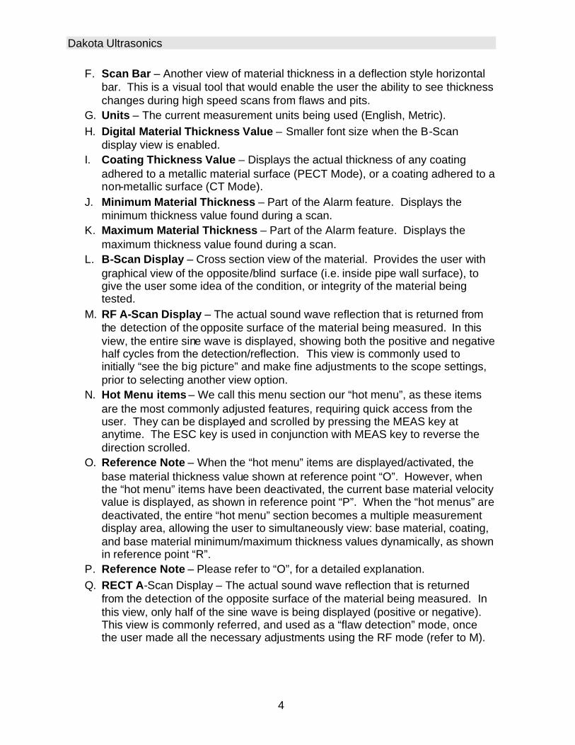
F. Scan Bar – Another view of material thickness in a deflection style horizontal bar. This is a visual tool that would enable the user the ability to see thickness changes during high speed scans from flaws and pits.
G. Units – The current measurement units being used (English, Metric). H. Digital Material Thickness Value – Smaller font size when the B-Scan
display view is enabled. I. Coating Thickness Value – Displays the actual thickness of any coating
adhered to a metallic material surface (PECT Mode), or a coating adhered to a non-metallic surface (CT Mode).
J. Minimum Material Thickness – Part of the Alarm feature. Displays the minimum thickness value found during a scan.
K. Maximum Material Thickness – Part of the Alarm feature. Displays the maximum thickness value found during a scan.
L. B-Scan Display – Cross section view of the material. Provides the user with graphical view of the opposite/blind surface (i.e. inside pipe wall surface), to give the user some idea of the condition, or integrity of the material being tested.
M. RF A-Scan Display – The actual sound wave reflection that is returned from the detection of the opposite surface of the material being measured. In this view, the entire sine wave is displayed, showing both the positive and negative half cycles from the detection/reflection. This view is commonly used to initially “see the big picture” and make fine adjustments to the scope settings, prior to selecting another view option.
N. Hot Menu items – We call this menu section our “hot menu”, as these items are the most commonly adjusted features, requiring quick access from the user. They can be displayed and scrolled by pressing the MEAS key at anytime. The ESC key is used in conjunction with MEAS key to reverse the direction scrolled.
O. Reference Note – When the “hot menu” items are displayed/activated, the base material thickness value shown at reference point “O”. However, when the “hot menu” items have been deactivated, the current base material velocity value is displayed, as shown in reference point “P”. When the “hot menus” are deactivated, the entire “hot menu” section becomes a multiple measurement display area, allowing the user to simultaneously view: base material, coating, and base material minimum/maximum thickness values dynamically, as shown in reference point “R”.
P. Reference Note – Please refer to “O”, for a detailed explanation. Q. RECT A-Scan Display – The actual sound wave reflection that is returned
from the detection of the opposite surface of the material being measured. In this view, only half of the sine wave is being displayed (positive or negative). This view is commonly referred, and used as a “flaw detection” mode, once the user made all the necessary adjustments using the RF mode (refer to M).

CMXDL+ High Performance Material & Coating Thickness Gauge
5
2.2 Auto Probe Recognition When the CMXDL+ is initially powered up, the gauge will automatically check to see if the transducer plugged into the gauge can be recognized. The steps that follow assume the CMXDL+ recognized the probe type:
Probe Automatically Recognized
1) Press the OK key once to use the identified probe, or ESC to display a list of
optional transducers. Note: if the CMXDL+ recognizes a specific
transducer, the user should always select OK to use the identified probe.
The only time an alternative probe should be selected from a list is if the
user switched probes following initial power up and recognition.
2) Assuming the CMXDL++ recognized the probe and the OK key was pressed,
the CMXDL+ will advance to a Zero Probe menu. If the transducer was
identified as a special transducer capable of measuring coating thickness, a
menu will be displayed allowing the user the ability to toggle the coating
thickness display on/off as follows:

Dakota Ultrasonics
6
3) Press the UP and DOWN arrow keys to toggle the coating option on/off.
4) Wipe all couplant from the transducer face and advance to the Probe Zero
& Calibration section outlined below.
2.3 Selecting the Transducer Type If the CMXDL+ does not identify a specific transducer type on initial power up, the user will be required to select a type from a predefined list of types by diameter and frequency. By selecting a transducer type from a predefined list, the CMXDL+ can recall specific properties about the transducer. Note: Once the transducer has been selected, the CMXDL+ will store and recall this transducer type every time the CMXDL+ is powered on/off. The type will only change if the user physically selects another transducer type from the list, or selects a previously saved setup. However, the CMXDL+ will continue to take you through these steps each time the gauge is powered up. You’ll notice that the probe type previously selected will be highlighted every time the probe type screen is displayed. Use the following steps to select your transducer type:

CMXDL+ High Performance Material & Coating Thickness Gauge
7
Selecting the Transducer Type
1) Press the OK or ESC keys to display the factory list of transducer types (by
diameter and frequency).
2) Press the UP and DOWN arrow keys to scroll through the transducer list
until the appropriate type is highlighted.

Dakota Ultrasonics
8
3) Press the ENTER key to select the transducer type and display overwrite
existing probe screen.
4) Press the OK key to overwrite the existing probe type with the newly
selected probe type. The zero probe screen will be displayed. Proceed to
the zero probe section that follows.
2.4 Probe Zero & Calibration The next steps are to perform a probe zero and calibrate the CMXDL+ to the material and transducer being used. If the sound velocity is unknown, the CMXDL+ can be calibrated to a known thickness sample. This demo will briefly explain both of these techniques. The CMXDL+ is equipped with two zero options:
1) Off Block Zero (Automatic Probe Zero) – When this feature is enabled the CMXDL+ will do an electronic zero automatically, eliminating the need for a zero disk or block.
2) On Block Zero (Manual Probe Zero) – When this feature is enabled the transducer must be placed on the probe zero disk (battery cover located on the top of the unit.
Note: Transducers of the same type will have very slight mechanical and electrical variations. If it’s discovered that the linearity is off following an initial auto probe zero and extreme accuracy is required, a manual zero should be performed followed by an auto zero. This will adjust and eliminate any error. This is only required if it’s discovered the transducer is non-linear following an initial auto probe zero. The procedures are outlined as follows:

CMXDL+ High Performance Material & Coating Thickness Gauge
9
Performing an Auto Probe Zero (Off Block)
Coating Probe Identified Coating Probe Not Identified
1) Be sure all couplant has been removed from the face of the transducer.
2) Press the OK key to perform the automatic probe zero, or ESC key to
cancel the zero operation.
Coating Probe Identified Coating Probe Not Identified
3) The screens illustrated above will be briefly displayed followed by the main
measurement screen. The CMXDL+ is ready to be calibrated.
Dakota Ultrasonics
10
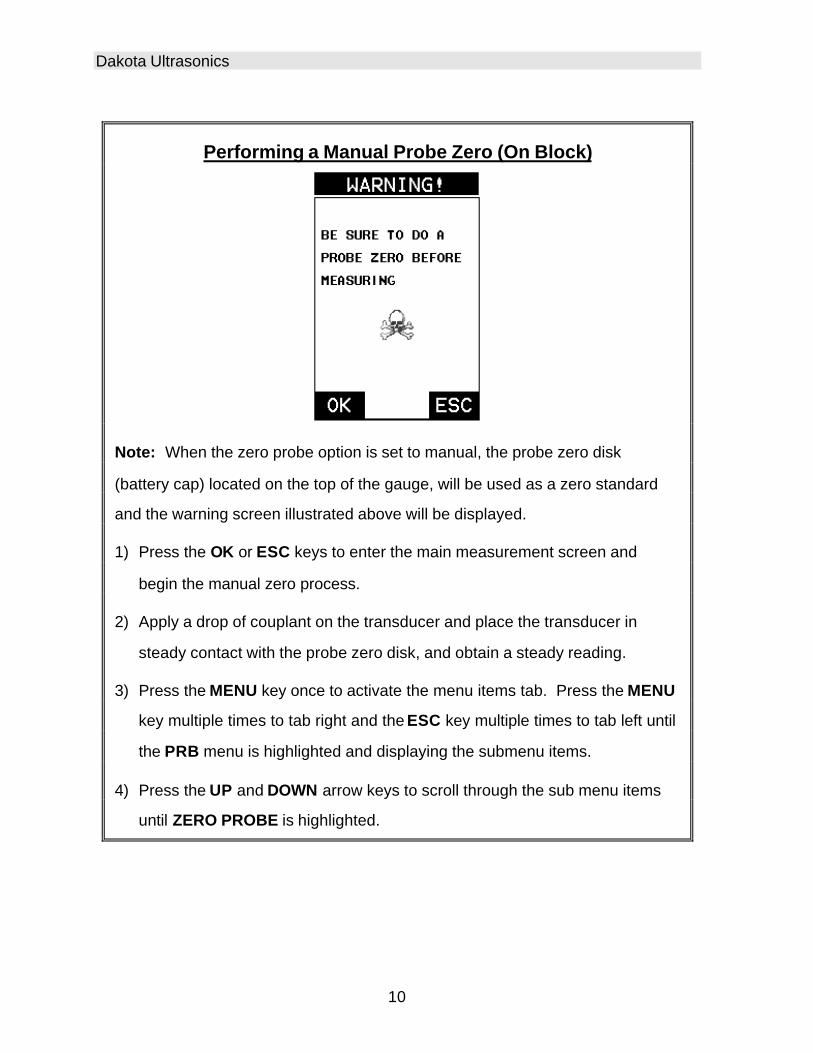
Performing a Manual Probe Zero (On Block)
Note: When the zero probe option is set to manual, the probe zero disk
(battery cap) located on the top of the gauge, will be used as a zero standard
and the warning screen illustrated above will be displayed.
1) Press the OK or ESC keys to enter the main measurement screen and
begin the manual zero process.
2) Apply a drop of couplant on the transducer and place the transducer in
steady contact with the probe zero disk, and obtain a steady reading.
3) Press the MENU key once to activate the menu items tab. Press the MENU
key multiple times to tab right and the ESC key multiple times to tab left until
the PRB menu is highlighted and displaying the submenu items.
4) Press the UP and DOWN arrow keys to scroll through the sub menu items
until ZERO PROBE is highlighted.

CMXDL+ High Performance Material & Coating Thickness Gauge
11
Coating Probe Identified Coating Probe Not Identified
5) Press the ENTER key to display the confirmation screen.
6) If a coating transducer was identified use the UP and DOWN arrow keys to
toggle coating on/off.
7) Press the OK key to complete the probe zero function, or ESC key to cancel
the probe zero function.
8) Remove the transducer from the probe zero disk, and proceed to the
calibration section.
Note: The value that is displayed will change depending on the current velocity
setting in the CMXDL+. Disregard the number that is displayed. It is not
important. What is important is accurately performing the steps outlined above
to insure reliability of the probe zero calculation.
One Point Material Calibration For the purposes of this quick start section, we’ll only be covering the most common one point calibration option to determine the sound velocity of the test material. It would be very handy to carry a set of mechanical calipers to use in conjunction with the CMXDL+ for calibration in the field:
Dakota Ultrasonics
12
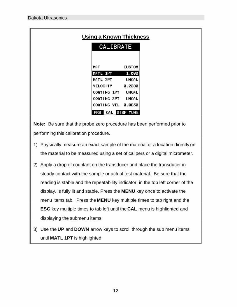
Using a Known Thickness
Note: Be sure that the probe zero procedure has been performed prior to
performing this calibration procedure.
1) Physically measure an exact sample of the material or a location directly on
the material to be measured using a set of calipers or a digital micrometer.
2) Apply a drop of couplant on the transducer and place the transducer in
steady contact with the sample or actual test material. Be sure that the
reading is stable and the repeatability indicator, in the top left corner of the
display, is fully lit and stable. Press the MENU key once to activate the
menu items tab. Press the MENU key multiple times to tab right and the
ESC key multiple times to tab left until the CAL menu is highlighted and
displaying the submenu items.
3) Use the UP and DOWN arrow keys to scroll through the sub menu items
until MATL 1PT is highlighted.
CMXDL+ High Performance Material & Coating Thickness Gauge
13
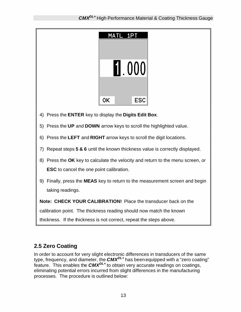
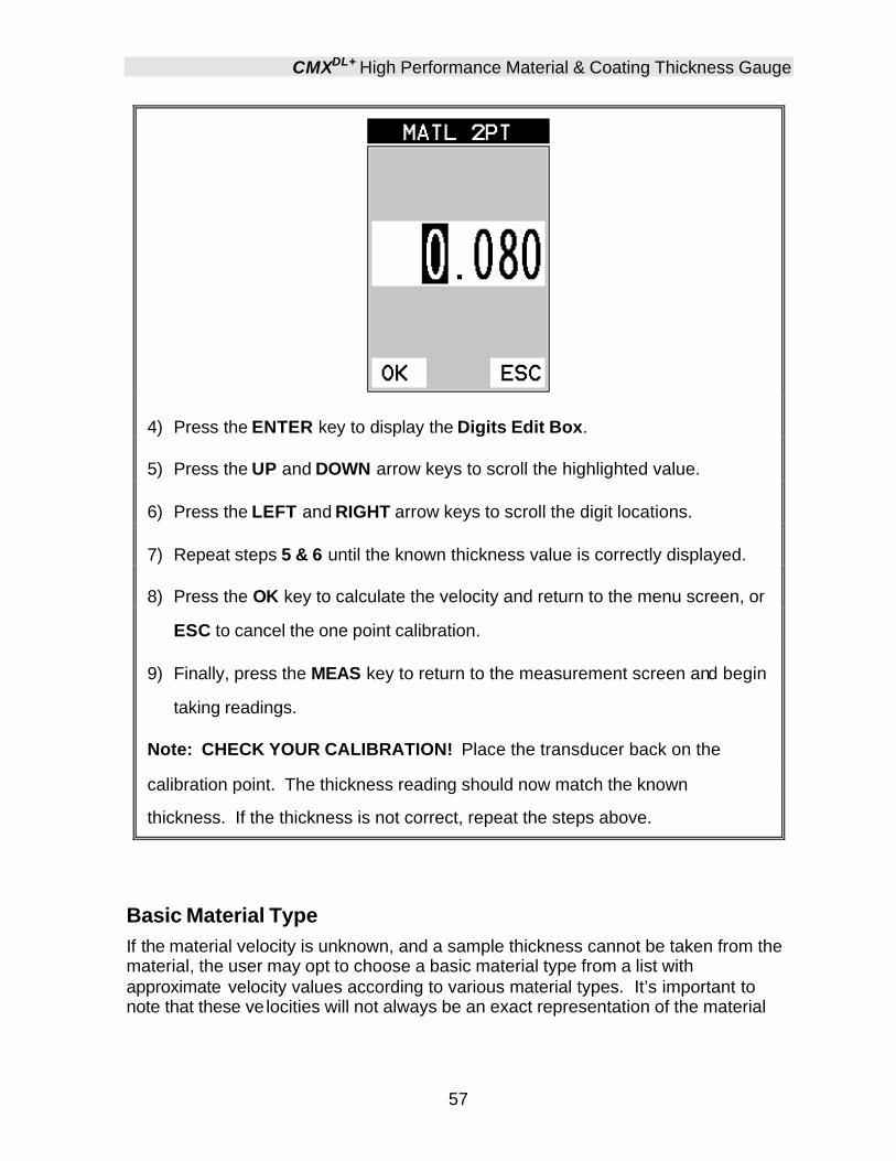
4) Press the ENTER key to display the Digits Edit Box.
5) Press the UP and DOWN arrow keys to scroll the highlighted value.
6) Press the LEFT and RIGHT arrow keys to scroll the digit locations.
7) Repeat steps 5 & 6 until the known thickness value is correctly displayed.
8) Press the OK key to calculate the velocity and return to the menu screen, or
ESC to cancel the one point calibration.
9) Finally, press the MEAS key to return to the measurement screen and begin
taking readings.
Note: CHECK YOUR CALIBRATION! Place the transducer back on the
calibration point. The thickness reading should now match the known
thickness. If the thickness is not correct, repeat the steps above.
2.5 Zero Coating In order to account for very slight electronic differences in transducers of the same type, frequency, and diameter, the CMXDL+ has been equipped with a “zero coating” feature. This enables the CMXDL+ to obtain very accurate readings on coatings, eliminating potential errors incurred from slight differences in the manufacturing processes. The procedure is outlined below:

Dakota Ultrasonics
14
Performing a Coating Zero
1) Press the MULTI MODE key once to activate the measurement mode
options.
2) Use the UP and DOWN arrow keys to scroll through the sub menu items
until Coating Only (CT) mode is highlighted.
3) Press the ENTER key to select the measurement mode and return to the
measurement screen.
4) Apply a drop of couplant on the transducer and place the transducer in
steady contact with the probe zero disk (battery cover) and obtain a steady
reading.
Note: The coating measurement displayed will potentially be a value greater or
less than 0.
5) Press the MENU key once to acti vate the menu items tab. Press the MENU
key multiple times to tab right and the ESC key multiple times to tab left until
the PRB menu is highlighted and displaying the submenu items.

CMXDL+ High Performance Material & Coating Thickness Gauge
15
6) Use the UP and DOWN arrow keys to scroll through the sub menu items
until ZERO COATING is highlighted.
7) Press the ENTER key to display the confirmation screen.
8) Press the OK key to zero the coating and return to the PRB menu, or ESC
to cancel the coating zero process.
9) Press the MULTI MODE key once to activate the measurement mode
options.
10) Use the UP and DOWN arrow keys to scroll through the sub menu items
until Coating On (PECT) is highlighted.
11) Press the ENTER key to select the measurement mode and return to the
measurement screen, and begin taking readings.
2.6 Coating Calibration The CMXDL+ has been preset to a default coating velocity of 0.0850 in/µsec (2159 m/sec). This will be very close to the most common coating material velocities used in the field. If the velocity of the coating is known, and different than the above default setting, the user can simply enter the coating velocity into the CMXDL+. However, if the velocity is unknown, the CMXDL+ can also be calibrated to a specific coating sample/type using the 1pt calibration option in PECT (pulse-echo coating) mode, or a two point calibration is CT (coating only) mode. For the purpose of this
Dakota Ultrasonics
16
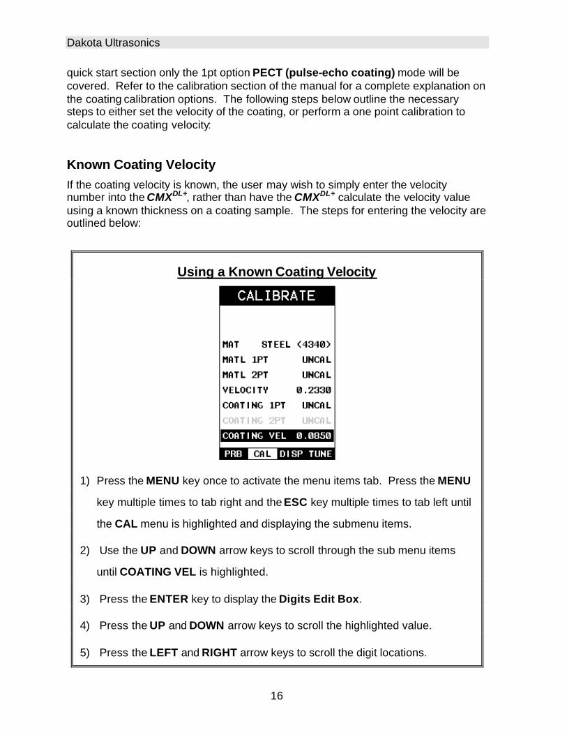
quick start section only the 1pt option PECT (pulse-echo coating) mode will be covered. Refer to the calibration section of the manual for a complete explanation on the coating calibration options. The following steps below outline the necessary steps to either set the velocity of the coating, or perform a one point calibration to calculate the coating velocity:
Known Coating Velocity If the coating velocity is known, the user may wish to simply enter the velocity number into the CMXDL+, rather than have the CMXDL+ calculate the velocity value using a known thickness on a coating sample. The steps for entering the velocity are outlined below:
Using a Known Coating Velocity
1) Press the MENU key once to activate the menu items tab. Press the MENU
key multiple times to tab right and the ESC key multiple times to tab left until
the CAL menu is highlighted and displaying the submenu items.
2) Use the UP and DOWN arrow keys to scroll through the sub menu items
until COATING VEL is highlighted.
3) Press the ENTER key to display the Digits Edit Box.
4) Press the UP and DOWN arrow keys to scroll the highlighted value.
5) Press the LEFT and RIGHT arrow keys to scroll the digit locations.

CMXDL+ High Performance Material & Coating Thickness Gauge
17
6) Repeat steps 4 & 5 until the velocity number is correctly displayed.
7) Press the OK key to set the coating velocity and return to the menu screen,
or ESC to cancel entering the coating velocity.
8) Finally, press the MEAS key to return to the measurement screen and
begin taking readings.
Known Coating Thickness When the exact velocity of a coating is unknown, the user has the option of performing a one point calibration on a sample of the coating with a known thickness to determine the sound velocity. It would be very handy to carry a set of mechanical calipers to use in conjunction with the CMXDL+ for calibration in the field:
Using a Coating Sample to Calibrate
1) Physically measure a location on a coating sample using a set of calipers or
a digital micrometer.

Dakota Ultrasonics
18
Important Note: In PECT (pulse-echo coating) mode, the coating sample must
be coupled to metal in order to calibrate successfully. Simply place a drop of
couplant on a piece of metal, lay the coating sample over the couplant on the
metal and proceed to step 2.
2) Apply a drop of couplant on the transducer and place the transducer in
steady contact with the coating (on metal) sample or actual test material. Be
sure that the reading is stable and the repeatability indicator, in the top left
corner of the display, is fully lit and stable. Press the MENU key once to
activate the menu items tab. Press the MENU key multiple times to tab right
and the ESC key multiple times to tab left until the CAL menu is highlighted
and displaying the submenu items.
3) Use the UP and DOWN arrow keys to scroll through the sub menu items
until COATING 1PT is highlighted.
4) Press the ENTER key to display the Digits Edit Box.
5) Press the UP and DOWN arrow keys to scroll the highlighted value.
6) Press the LEFT and RIGHT arrow keys to scroll the digit locations.
7) Repeat steps 5 & 6 until the known thickness value is correctly displayed.

CMXDL+ High Performance Material & Coating Thickness Gauge
19
8) Press the OK key to calculate the coating velocity and return to the menu
screen, or ESC to cancel the one point calibration.
9) Finally, press the MEAS key to return to the measurement screen and begin
taking readings.
Note: CHECK YOUR CALIBRATION! Place the transducer back on the
calibration point. The coating thickness reading should now match the known
coating thickness sample. If the thickness is not correct, repeat the steps
above.
2.7 Measure The CMXDL+ is now ready to measure. There are four different measurement view options, each with a specific purpose – Digits, RF, RECT, & B-Scan. The steps below outline how to toggle between the different view mode options:
Selecting the Measurement View Option
1) Press the MENU key once to activate the menu items tab. Press the MENU
key multiple times to tab right and the ESC key multiple times to tab left until
the DISP menu is highlighted and displaying the submenu items.
Dakota Ultrasonics
20
2) Use the UP and DOWN arrow keys to scroll through the sub menu items
until VIEW is highlighted.
3) Use the LEFT and RIGHT arrow keys to scroll the view options.
4) Once the view is displayed, press the MEAS key to return to measurement
mode.
DIGITS: Displays the digital thickness value using a large font size. This view is useful when the CMXDL+ is being used as a basic thickness gauge. RF: Displays the actual waveform signal, much like an oscilloscope, from the reflection of the opposite surface, pit, flaw, crack or void. This view shows both the positive and negative peaks, and is often used to fine tune the scope settings, prior to inspection. RECT: Displays a half waveform signal, either positive or negative, from the reflection of the opposite surface, pit, flaw, crack or void. The user can select the polarity or “phase” displayed. This is typically determined by first using RF view to select the most optimal polarity “phase”, to fine tune the scopes settings. The RECT view is commonly used as the primary “flaw detection” view. BSCAN: The Time Based B-Scan provides the user with a cross sectional view of the material being tested. This mode is useful when there is concern regarding the profile of the blind surface. This can also be a useful view when scanning for pits and flaws. Once the view has been selected according to the application requirements, the Delay and Range of the screen will potentially need to be adjusted, if the view has been set to RF or RECT. Alternatively, if BSCAN was selected, the B-Start and B-Depth settings will need to be adjusted. These settings serve the same purpose, with only differences in terminology. The Delay the same as B-Start, and the Range is the same as B-Depth. Therefore, these items will be grouped together for the duration of this manual, as follows: Delay (B-Start) and Range (B-Depth). Use the following steps to adjust these settings directly from the measurement screen as follows: Note: The Delay (B-Start) and Range (B-Depth) are also used to adjust the parameters of Scan Bar.

CMXDL+ High Performance Material & Coating Thickness Gauge
21
Adjusting Delay (B-Start) & Range (B-DEPTH)
1) Press the MEAS key once to activate the measure menu items. Press the
MEAS key multiple times to move right and the ESC key multiple times to
move left, until the either the DELAY (START) or RANGE (DEPTH) cell is
highlighted.
2) Use the UP, DOWN, LEFT, or RIGHT arrow keys to scroll the DELAY
(START) and RANGE (DEPTH) values.
3) Repeat steps 1 & 2 until the range is correctly being displayed.
Alternatively, the DELAY (START) and RANGE (DEPTH) values can be
changed using the Digit Edit Box as follows:
4) Press the MEAS key once to activate measure menu items. Press the
MEAS key multiple times to move right and the ESC key multiple times to
move left, until the either the DELAY (START) or RANGE (DEPTH) cell is
highlighted.

Dakota Ultrasonics
22
1) Press the ENTER key to display the digits edit box.
2) Press the UP and DOWN arrow keys to scroll the highlighted value.
3) Press the LEFT and RIGHT arrow keys to scroll the digit locations.
4) Repeat steps 3 & 4 until the DELAY (START) or RANGE (DEPTH) value is
correctly displayed.
5) Press the OK key to set the DELAY (START) and WIDTH (DEPTH) value
and return to the measure screen, or ESC to cancel entering the DELAY
(START) or WIDTH (DEPTH) value.
6) Finally, press the MEAS key to return to the measurement screen and begin
taking readings.
Note: The DELAY (START) & WIDTH (DEPTH) can also be adjusted from the
tabbed menu item DISP. However, using the hot menu keys is the easiest
method.

CMXDL+ High Performance Material & Coating Thickness Gauge
23
RF View Rectified (RECT) View
BSCAN View DIGITS View
In the upper left corner of each of the display photos above, is the repeatability indicator. The repeatability indicator is represented by six vertical bars and represents how repeatable the measurements are. In regular measurement mode, the CMXDL+ makes 8 measurements a second. In scan mode, the CMXDL+ makes 200 measurements a second. If the coating mode option is activated, the CMXDL+ makes 3 measurements a second in regular measurement mode and 65 measurements a second in scan mode. When the CMXDL+ is idle, only the left vertical bar will be displayed. However, when the CMXDL+ is making a measurement, four or five of the bars should be displayed on the repeatability indicator. If fewer than four bars are showing, the CMXDL+ is having difficulty achieving a stable measurement and the thickness value displayed is potentially unstable.

24
CHAPTER THREE KEYBOARD, MENU, & CONNECTOR REFERENCE
3.1 Menu Key (Operation & Sub Menus) The Menu key activates the primary menu structure containing 8 menu tab groups. These tab groups then contain sub menu items, or functions. The sub menu items have been organized in tab groups according to how closely they are related to the individual tab group names. Let’s first get familiar with how to move around in these tabs before continuing on to the sub menu functions. This procedure is outlined below:

CMXDL+ High Performance Material & Coating Thickness Gauge
25
Activating and Getting Around in the Menu Items
1) Press the MENU key once to activate the menu items tab. Press the MENU
key multiple times to tab right, and the ESC key multiple times to tab left
until the desired tab group is highlighted and displaying the submenu items.
The tab groups are illustrated above (A).
Now that you’re familiar with activating and moving amongst the tab groups, let’s have a look at how to move around in the sub menu items as follows:
Getting Around in the Sub Menu Items
1) Use the UP and DOWN arrow keys to scroll through the sub menu items
until the desired function is highlighted. The sub menu items are illustrated
in the diagram above (B).
2) Depending on which function is highlighted, use the LEFT, RIGHT, and
Enter keys to scroll the options or activate the Digit Edit and List Box
options.
The sections to follow will provide the user with an explanation of the sub menu functions:

Dakota Ultrasonics
26
3.2 Probe – Menu ZERO PROBE: The CMXDL+ is zeroed in much the same way that a mechanical micrometer is zeroed. If the CMXDL+ is not zeroed correctly, all of the measurements made using the CMXDL+ may be in error by some fixed value. The CMXDL+ is equipped with an optional automatic or manual zero feature. Refer to the section on page 48, for an explanation of this important procedure. ZERO COATING: In order to account for very slight electronic differences in transducers of the same type, frequency, and diameter, the CMXDL+ has been equipped with a “zero coating” feature. This enables the CMXDL+ to obtain very accurate readings on coatings, eliminating potential errors incurred from slight differences in the manufacturing processes. Refer to the section on page 48, for a detailed explanation. TYPE: Enables the user to select the type of transducer being used from a chart of transducer types. This provides increased linearity between transducers. Refer to page 44 for a further explanation. FLAW MODE: Activates the flaw detection mode and view. This feature is for use with single element angle beam transducers and used as a general prove-up flaw inspection mode. Refer to page 120 for a further explanation.
3.3 CAL – Menu MAT: Select the material velocity from a chart of basic material types when a known sample thickness, or material velocity cannot be obtained. Refer to page 57 for further info. MATL 1PT: Performs a single point calibration. This option allows the user to automatically calculate the velocity by entering a known sample thickness. Refer to page 54 for further info.

CMXDL+ High Performance Material & Coating Thickness Gauge
27
MATL 2PT: Performs a two-point calibration. This option allows the user to automatically calculate the velocity by entering a second known sample thickness. Refer to page 56 for further info. VELOCITY: Function to calibrate the CMXDL+ by setting the velocity to a known material velocity. Refer to page 52 for further info. COATING 1PT: Performs a single point coating calibration. This option allows the user to automatically calculate the velocity by measuring a known coating sample thickness. Refer to page 104 for further info. COATING 2PT: Performs a two-point coating calibration. This option allows the user to automatically calculate the velocity by entering a second known coating sample thickness. Refer to page 104 for further info. COATING VEL: Function to calibrate the CMXDL+ to a specific coating material type by entering a coating velocity. Refer to page 16 or page 98 for further info.
3.4 DISP (display) – Menu VIEW: Selectable BSCAN (cross section), and DIGITS (large digits) views. Refer to page 61 for further info. DELAY (B-START): Provides the user the ability to change the start position of the B-SCAN view. Refer to page 69 for further info. RANGE (B-DEPTH): Provides the user the ability to change the overall depth of the viewable measurement area. It functions a lot like a zoom on a camera. Refer to page 71 for further info. B-SCAN SPEED: (color version only) – Controls the speed of the time based B-Scan with an arbitrary scale of 0-10, with 10 being the fastest scrolling speed. Default speed set at 6. Refer to page 73 for further info. UNITS: Toggle between English or Metric units. The readout will change from inches to millimeters. BACKLIGHT: Selectable OFF, ON, AUTO, or INVERT backlight option. Note: Color version uses an AMOLED display, and ‘Brightness’ is substituted for Backlight as the menu item label, with an arbitrary scale of 1 -20, with the brightest setting at 20. Refer to page 115 for further info. CONTRAST: Adjustable display contrast for variable light conditions. Note: This menu item is eliminated in the color version.

Dakota Ultrasonics
28
VIEW: (color version only) – Provides the user with 12 different color schemes to select from. There are two schemes for each main color option. Refer to page 117 for further info. DIM: (color version only) – Allows the user to conserve battery life by diming the display after idle for a specific amount of time – OFF, 30, 60, 90, 120 seconds. Once dimmed, a single press of any key will restore the screen brightness. Refer to page 118 for further info. RECT WAVE: This option provides the user an outlined or filled view option when the display setting is in RECT (rectified) wave mode only. Refer to page 123 for further info. DETECT MARK: Selectable graphics option for the point of detection on the waveform: Line, Box, Dots, None. Offers the user a graphics preference on how they prefer to view the detection on the waveform.
3.5 TUNE – Menu MEASURE MODE: Toggles a variety of unique measurement modes for different application requirements: Coating Off (P-E), Coating On (PECT), Temp Comp (PETP), Thru Coat (E-E), Thru Verify (E-EV), Coating Only (CT). Refer to page 37 for further info. POLARITY: The CMXDL+ operates on a zero crossing detection principle. This feature toggles which stroke of the cycle the crossing detection uses, either positive or negative. Refer to page 125 for further info. PULSE: The CMXDL+ has an adjustable pulse width for both high penetration and resolution applications. The pulse width refers to the duration of time the pulser is on. The options are Spike, Thin , and Wide. Refer to page 127 for a further explanation. PULSER VOLTAGE: This feature offers a 50 volt cut/boost to the pulser. The standard setting is 150 volts. This enables the CMXDL+ to offer greater penetration for difficult material types, or increased resolution on noisy materials. Refer to page 128 for a further explanation. DAMPING: (color version only) – Provides the user with multiple input impedances to match the impedance of the transducer, and optimized overall transducer performance. Refer to page 119 for further info.

CMXDL+ High Performance Material & Coating Thickness Gauge
29
ATTN: This feature is a 20dB attenuator, as well as a 20dB amplifier. The primary purpose is to is to offer further flexibility to the CMXDL+ , by either cutting or boosting signal strength. In instances where the 60 dB range is not enough, or too much, this feature allows you to increase/decrease the amplifier strength by a power of 10 or (20dB). The standard setting is zero, which is an arbitrary value at a constant attenuation. The attenuation value is added to the gain value. Therefore, if the attenuator is increased to 20dB, this value is added to the value of the gain setting. Refer to page 129 for a further explanation. GAIN: The CMXDL+ has 100dB gain range from (-30 to 70 dB), used in conjunction with the attenuator feature above. This feature is used to increase/decrease the power or amplitude of the signal. This might easily be considered as similar to turning the volume up or down on a stereo receiver. Refer to page 74 for further info. AGC: This an automatic gain control used in E-E (echo-echo), and E-EV (echo-echo verify). The CMXDL+ is equipped with an automatic gain control when operating in -E (echo-echo), and E-EV (echo-echo verify) modes only. This feature automatically increases/decreases the power or amplitude of the signal, to an optimal input to output signal ratio. This might easily be considered as similar to turning the volume up or down on a stereo receiver. Alternatively, the AGC can be manually controlled. The CMXDL+ is equipped with manual override, using an arbitrary range of 1-20 clicks. The higher the number the better the dynamic gain range, and visa versa. Refer to page 74 for further info.
3.6 GT1 – Menu GATE1: Gates allow the user to view a specific measurement range, or sections of the waveform, and ignore others. The Gate1 feature adjusts the start of the gate, according to time/distance. Gate 1 can be used in all pulse-echo and echo-echo measurement modes. Refer to page 83 for further info. GATE1 WIDTH: This feature allows the user to set the overall width of the gate, in terms of distance, from the starting value of Gate1. Refer to page 83 for further info. THRESHOLD1: Enables the user to set the sensitivity level of Gate1. The amplitude of the signal must reach or exceed the threshold level before a measurement is detected. Refer to page 83 for further info.
3.7 GT2 – Menu

Dakota Ultrasonics
30
GATE2 WIDTH: This feature allows the user to set the overall width of the gate, in terms of distance, from the starting value of HoldOff2. Refer to page 83 for further info. HOLDOFF 2: Provides the user with the ability to delay the starting point of Gate2, a specific distance from the first detection point found inside of the boundaries of the Gate 1 settings. If no detection is found, the Gate1 width value is used as a starting value for Gate2. Refer to page 83 for further info. THRESHOLD2: Enables the user to set the sensitivity level of Gate2. The amplitude of the signal must reach or exceed the threshold level before a measurement is detected. Refer to page 83 for further info.
3.8 GT3 – Menu GATE3 WIDTH: This feature allows the user to set the overall width of the gate, in terms of distance, from the starting value of HoldOff3. Refer to page 83 for further info. HOLDOFF 3: Provides the user with the ability to delay the starting point of Gate3, a specific distance from the first detection point found inside of the boundaries of the Gate 2 settings. If no detection is found, the Gate2 width value is used as a starting value for Gate3. Refer to page 83 for further info. THRESHOLD3: Enables the user to set the sensitivity level of Gate3. The amplitude of the signal must reach or exceed the threshold level before a measurement is detected. Refer to page 83 for further info.
3.9 SETUP – Menu OPEN: Displays a list of factory and user defined setups currently stored in memory. These setups can be recalled and used at any time. Refer to page 157 for further info.

CMXDL+ High Performance Material & Coating Thickness Gauge
31
SAVE: Provides the user with the ability to save a custom setup that has been modified or created by the user. Refer to page 159 for further info. DELETE: Provides the user with the ability to delete specific setups previously save in memory. Refer to page 163 for further info. DEFAULT SETUP: Loads a basic default setup. Use only as a last resort when the setups in the CMXDL+ have been corrupted and a computer is not accessible. Refer to page 164 for further info. LANGUAGE: Provides the user the ability to select different languages for the CMXDL+. Refer to page 166 for further info.
3.10 DATA – Menu NEW: Allows the user the ability to create a new alpha numeric grid, or sequential log file with auto identifiers. It is equipped with custom parameters, rows, and columns depending on the user’s application reporting requirements. Refer to page 132 for further info. EDIT: Gives the user the ability to change parameters of grid or sequential file previously saved. Note: Pre-defined coordinates cannot be changed once they have been created. Refer to page 150 for further info. OPEN: This function provides the user with the ability to recall grids or sequential log files that currently exist in memory, from a list of grids. Refer to page 152 for further info. CLOSE: Provides the user the ability to close a currently opened grid or sequential log file. Refer to page 154 for further info. DELETE ONE FILE: This function provides the user with the ability to delete one individual grid or sequential log file from a list of multiple grids/files previously saved in memory. Refer to page 147 for further info. DELETE ALL DATA: This function provides the user with the ability to delete all files currently stored in memory. Refer to page 148 for further info.
3.11 UTIL (utilities) – Menu

Dakota Ultrasonics
32
AUTO FIND: Automatically locates the detection point if the measurement is out of the viewable display area. Refer to page 109 for further info. SCAN MODE: This function enables a hi speed scan mode that increases the overall sample rate from 65 to 200 measurements per second, depending on the current measurement mode used. Refer to page 109 for further info. ALARM: Toggles alarm mode on, off, or audible . Refer to page 111 for further info. ALARM HIGH: Gives the user the ability to set the HI limit parameter. If the measurement exceeds this value, a red light will illuminate and sound the internal beeper. Refer to page 111 for further info. ALARM LOW: Gives the user the ability to set the LO limit parameter. If the measurement falls below this value, a red light will illuminate and sound the internal beeper. Refer to page 111 for further info. DIFFERENTIAL: Gives the user the ability to set a nominal value and the CMXDL+ will display +/- the difference from the nominal value entered. Refer to page 113 for further info.
3.12 XFER (transfer) – Menu BACKUP SETUPS: Enables the user the ability to backup the setups currently stored in the CMXDL+ to a PC via RS232 port. Refer the help section of the CMXDL+ DakView software for a complete electronic manual. RESTORE SETUPS: Enables the user the ability to restore the setups currently saved on a PC to an CMXDL+ via RS232 port. Refer the help section of the CMXDL+ DakView software for a complete electronic manual. BACKUP DATA: Enables the user the ability to backup grids or sequential log files currently stored in the CMXDL+ to a PC via RS232 port. Refer the help section of the CMXDL+ DakView software for a complete electronic manual. RESTORE DATA: Enables the user the ability to restore grids or sequential log files currently saved on a PC to an CMXDL+ via RS232 port. Refer the help section of the CMXDL+ DakView software for a complete electronic manual. ABOUT: Provides the user with Dakota Ultrasonics contact information and the CMXDL+ software version. Refer the Dakota Ultrasonics web site for information on the latest firmware versions available for download.

CMXDL+ High Performance Material & Coating Thickness Gauge
33
3.13 CLR (clear) Key The primary functions of the CLR key, is to clear a measurement from a grid or sequential log files cell location or set obstruct, and backspace in an Alpha Edit Box. If a user has already saved a measurement and B-Scan to a cell location, use this key to clear the measurement at any time.
3.14 MEAS (measurement mode) Key The MEAS key puts the CMXDL+ into it’s primary mode of operation. In this mode, the user has a complete view of the LCD.
3.15 OK Key The primary function of the OK key is confirmation of a change or selection. The OK key also toggles the Hot Menu area, while in measurement mode, to a large digits display area. If the CMXDL+ is displaying a grid log, the OK key toggles an advance to row number option.
3.16 ESC Key The ESC key is used in the MENU, MEAS, and EDIT functions as a back or escape function. If the CMXDL+ is displaying a grid or sequential log, the OK key toggles the display options: Digits, RF, RECT, and B-Scan views.
3.17 Arrow Keys The Arrow Keys are used to navigate through the menus, increase/decrease values, and toggle specific function keys.
3.18 ENTER key
Dakota Ultrasonics
34
The ENTER key is used in the overall menu selection process, to activate list and edit boxes, display and save measurements to grid or sequential files locations.
3.19 MULTI MODE Key The MULTI MODE key opens a measurement mode screen, listing all the modes that are available to the transducer specifically selected, or autodetected. The modes can be all or a combination of the entire set of modes the CMXDL+ offers, depending on which transducer is being used as follows: Coating Off (P-E), Coating On (PECT), Temp Comp (PETP), Thru Coat (E-E), Thru Coat Verify (E-EV), and Coating Only (CT).
3.20 ON/OFF Key The ON/OFF key simply powers the unit either ON or OFF. Note: Unit will automatically power off when idle for 5 minutes. All current settings are automatically saved prior to powering off.

35
3.21 Top & Bottom End Caps
The top & bottom end panels are where all connections are made to the CMXDL+. The diagram above shows the layout and description of the connectors:
Transducer Connectors
Refer to Diagram: The transducer connectors, and battery cover/probe zero disk are located on the CMXDL+’s top end cap. The transducer connectors are of type Lemo “00”. Note: There is no polarity associated with connecting the transducer to the CMXDL+.
Probe Zero Disk & Battery Cover
Refer to Diagram: The Battery cover is the large round disk shown in the diagram. Note: This same disk is also used as a probe zero disk. Simply remove the cover when replacing the batteries (3 AA cells). When performing a manual probe zero function, simply place the transducer on disk making firm contact. Important: Be sure to follow the polarity labels located on the back label of the CMXDL+. Note: Rechargeable batteries can be used, however they must be recharged outside of the unit in a stand alone batte ry charger.
RS-232 Connector
Refer to Diagram: The RS-232 connector, located on the bottom end cap, is a 2 pin female Lemo connector. It is designed to connect directly from the CMXDL+ to a standard AT serial port on a PC. The cable supplied with the CMXDL+ is a Lemo to 9 pin serial cable. Note: This connector is also used to upgrade the CMXDL+ with the latest version of firmware.
USB Serial to USB Converter Cable
A converter cable can be attached to the 9 pin serial cable in needed (part no. N-402-0510).

36
CHAPTER FOUR PRINCIPALS OF ULTRASONIC MEASUREMENT
4.1 Time versus thickness relationship Ultrasonic thickness measurements depend on measuring the length of time it takes for sound to travel through the material being tested. The ratio of the thickness versus the time is known as the sound velocity. In order to make accurate measurements, a sound velocity must be determined and entered into the instrument. The accuracy of a thickness measurement therefore depends on having a consistent sound velocity. Some materials are not as consistent as others and accuracy will be marginal. For example, some cast materials are very granular and porous and as a result have inconsistent sound velocities. While there are many different ultrasonic techniques to measure thickness, which will be discussed below, all of them rely on using the sound velocity to convert from time to thickness.
4.2 Suitability of materials Ultrasonic thickness measurements rely on passing a sound wave through the material being measured. Not all materials are good at transmitting sound. Ultrasonic thickness measurement is practical in a wide variety of materials including metals, plastics, and glass. Materials that are difficult include some cast materials, concrete, wood, fiberglass, and some rubber.
4.3 Range of measurement and accuracy The overall measurement capabilities, based on the wide variety of materials, is determined by the consistency of the material being measured The range of thickness that can be measured ultrasonically depends on the material as well as the technique being used and the type of transducer. Thickness measurements can be made from a minimum of 0.010 inch to 9.999” in steel. However, the maximum attainable thickness is much less for more attenuative materials (materials that absorb sound). Accuracy, is determined by how consistent the sound velocity is through the sound path being measured, and is a function of the overall thickness of the material. For example, the velocity in steel is typically within 0.5% while the velocity in cast iron can vary by 4%.
4.4 Couplant All ultrasonic applications require some medium to couple the sound from the transducer to the test piece. Typically a high viscosity liquid is used as the medium. The sound frequencies used in ultrasonic thickness measurement do not travel

CMXDL+ High Performance Material & Coating Thickness Gauge
37
through air efficiently. By using a liquid couplant between the transducer and test piece the amount of ultrasound entering the test piece is much greater.
4.5 Temperature Temperature has an effect on sound velocity. The higher the temperature, the slower sound travels in a material. High temperatures can also damage transducers and present a problem for various liquid couplants. Since the sound velocity varies with temperature it is important to calibrate at the same temperature as the material being measured.
Normal temperature range
Most standard transducers will operate from 0°F to 180°F.
High temperature measurements
Special transducers and couplants are available for temperatures above 180°F up to 650°F with intermittent contact. It is necessary to cool the transducer, by submerging the transducer in water between readings, when measuring high temperatures.
Modes and temperature errors
In addition to errors caused by velocity changing with temperature, some modes (measurement techniques) are affected more than others. For example, dual element pulse-echo mode has larger errors due to changes in the temperature of the delay line. However, multi-echo techniques offer temperature compensation help to minimize these errors.
4.6 Measurement Modes In this section we will discuss the different measurements modes the CMXDL+ is capable of operating in, the transducers required, and the reasons for using specific modes:
Pulse-Echo Mode (Flaw & Pit detection) – Coating Off (P-E)
Pulse-echo mode measures from the initial pulse (sometimes referred to as an artificial zero) to the first echo (reflection). In this mode, either an automatic or manual zero can be performed depending on the zero probe function setting. If the manual mode has been selected, the transducer is placed on a reference disk, located on top of the CMXDL+, and a key is pressed to establish a zero point for the particular transducer. If the Auto Zero feature is enabled, a simple key press will perform an electronic zero to establish the same zero point. In this mode errors result from surface coatings and temperature variations. Since pulse-echo only requires one reflection, it is the most sensitive mode for measuring weak reflections (flaws) typically found when measuring heavily corroded metals.

Dakota Ultrasonics
38
V-Path Correction
Dual element delay line transducers have two piezoelectric elements mounted at an angle on one end of the delay line. One element is used for transmitting sound, while the other element only receives sound. The two elements and their delay lines are packaged in a single housing but acoustically isolated from each other with a sound barrier. This allows the transducer the ability to achieve very high sensitivity for detecting small defects. Also, the surface of the test material does not have to be as flat in order to obtain good measurements. Dual element transducers are normally used in pulse-echo mode for finding defects, and in echo-echo mode for through coating measurements. Dual element delay line transducers are usable over a range of 0.025 inches to 20 inches depending on the material, frequency, and diameter. A limitation of dual element delay-line transducers is the V shaped sound path. Because the sound travels from one element to another, the time versus thickness relationship is non-linear. Therefore, a correction table in the instruments software is used to compensate for this error.
Dual Element Transducer showing V-path of signal
Searching for small defects
Dual element delay line transducers are especially useful in searching for small defects. In the pulse-echo mode with high amplifier gain, very small defects can be measured. This is very useful during corrosion inspections overall. The dual element style transducer will find wall deterioration, pits, and any porosity pockets during tank and pipeline inspections.
Echo-Echo Mode – Thru Coat (E-E)
The echo-echo mode measures between two reflections. This technique is commonly used to eliminate errors from surface coatings and also to make measurements in multiple layered materials. The disadvantage is that two echoes are needed which requires a much stronger echo (reflection).
CMXDL+ High Performance Material & Coating Thickness Gauge
39
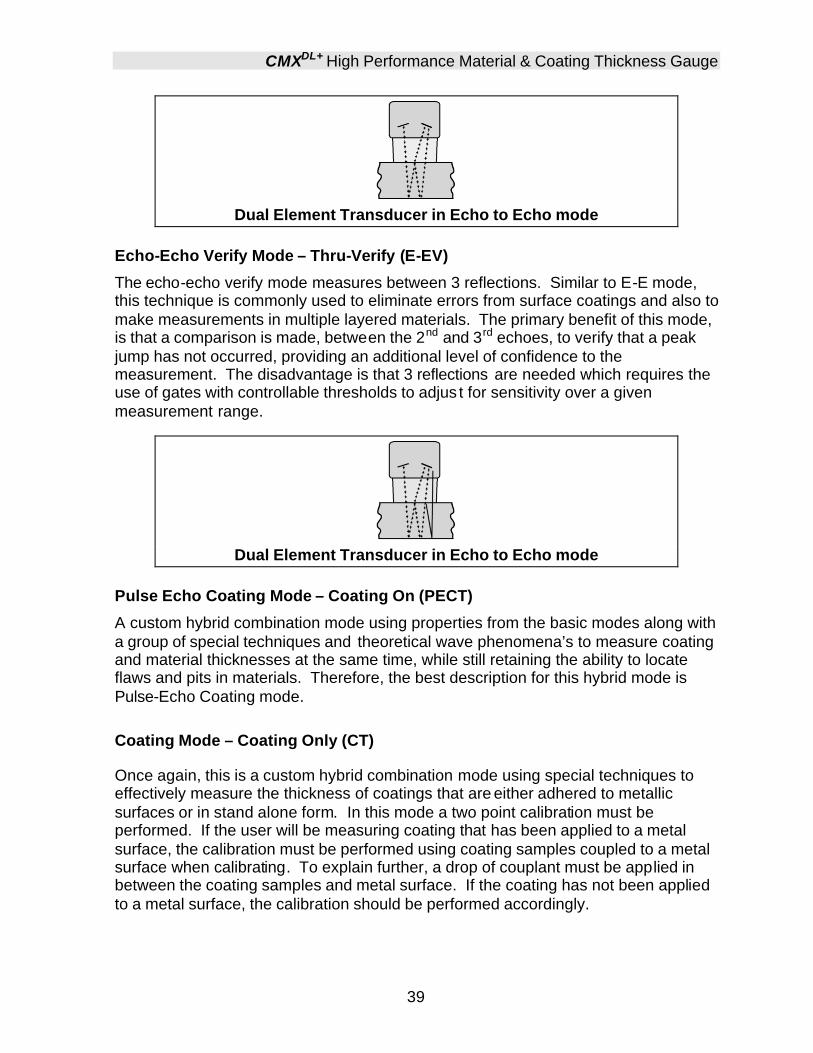
Dual Element Transducer in Echo to Echo mode
Echo-Echo Verify Mode – Thru-Verify (E-EV)
The echo-echo verify mode measures between 3 reflections. Similar to E-E mode, this technique is commonly used to eliminate errors from surface coatings and also to make measurements in multiple layered materials. The primary benefit of this mode, is that a comparison is made, between the 2nd and 3rd echoes, to verify that a peak jump has not occurred, providing an additional level of confidence to the measurement. The disadvantage is that 3 reflections are needed which requires the use of gates with controllable thresholds to adjus t for sensitivity over a given measurement range.
Dual Element Transducer in Echo to Echo mode
Pulse Echo Coating Mode – Coating On (PECT)
A custom hybrid combination mode using properties from the basic modes along with a group of special techniques and theoretical wave phenomena’s to measure coating and material thicknesses at the same time, while still retaining the ability to locate flaws and pits in materials. Therefore, the best description for this hybrid mode is Pulse-Echo Coating mode. Coating Mode – Coating Only (CT)
Once again, this is a custom hybrid combination mode using special techniques to effectively measure the thickness of coatings that are either adhered to metallic surfaces or in stand alone form. In this mode a two point calibration must be performed. If the user will be measuring coating that has been applied to a metal surface, the calibration must be performed using coating samples coupled to a metal surface when calibrating. To explain further, a drop of couplant must be applied in between the coating samples and metal surface. If the coating has not been applied to a metal surface, the calibration should be performed accordingly.

Dakota Ultrasonics
40
Pulse-Echo Temperature Compensated Mode – Temp Comp (PETP) This is a custom mode that combines pulse-echo and electronic zero techniques to automatically adjust for temperature changes in the transducer as a result of an increasing/decreasing temperature gradient in the test material. Note: rough surface conditions can have an effect on the overall accuracy in this mode. If the surface condition is in question, the pulse-echo mode should be used in conjunction with performing an off block automatic zero as the temperature gradient changes.

41
CHAPTER FIVE SELECTING THE MEASUREMENT MODE
5.1 The setup library The CMXDL+ contains 64 user configurable preset locations to store custom setups for easy recall. These setups can be optimized for the user’s specific application needs and can also be stored on a PC and transferred bi-directionally using Dakota’s PC interface software included with the instrument. The setups supplied with the instrument cover some of the more typical applications commonly used with this type of instrument. These setups can be recalled, modified, and overwritten to one of 64 setup locations. Therefore, these factory setups can also be considered a good starting point to be modified for custom applications. The PC software includes a default setup file that can be uploaded to the gauge at any time to restore factory settings. However, it is recommended that the user consider saving modified setups to an empty location rather than overwriting the factory setups in the CMXDL+. Once again, these factory settings are excellent starting points for custom setups.
5.2 Which mode & transducer do I use for my application?
High penetration plastics and castings
The most common mode for these types of applications is pulse-echo. The CMXDL+ has been optimized for cast materials. Cast iron applications require 1 - 5MHz frequencies, and cast aluminum requires a 10MHz frequency. Plastics typically require lower frequencies depending on the thickness and make-up of the material. Larger diameters offer greater penetration power because of the crystal size, for difficult to measure materials.
Corrosion & Pit Detection in steel and cast materials
Use pulse-echo mode whenever attempting to locate pits and flaws. Typically a 5MHz transducer, or higher, will be used for these types of applications. Use low frequencies for greater penetration and use higher frequencies for better resolution. Measuring Material & Coatings The pulse-echo coating mode should be used when both material and coating thickness are required, while still requiring the ability to detect flaws and pits. A special coating style transducer is required for use in this mode. There are a variety of coating transducers in various frequencies available from Dakota.

Dakota Ultrasonics
42
Thru Paint & Coatings
Often times, users will be faced with applications where the material will be coated with paint or some other type of epoxy material. Since the velocity of the coating is approximately 2.5 times slower than that of steel, pulse-echo mode will induce error if the coating or paint is not completely removed. By using echo-echo mode, the user is able to successfully measure through both, the coating and steel, and completely eliminate the thickness of the paint or coating. Therefore, the steel can be measured without having to remove the coating prior to measuring. Users will often use pulse-echo mode and echo-echo mode in conjunction when performing inspections on coated materials. Thru coating measurements require special high damped transducers. The most common transducers are the 3.5, 5, and 7.5MHz hi damped transducers. These transducers are suitable for use in both pulse-echo and echo-echo modes. This conveniently enables the user to accurately measure overall material thickness using the thru Coating mode, and then conveniently switch to pit detection mode without changing transducers. The ¼” 5MHz Hi damped transducer is the most commonly used transducer for standard thru coating applications. Coating Only The coating only mode should be used when the application calls for coating measurements only and the user is not interested in the thickness of the material the coating has been applied to. This mode can also be used as a stand alone coating thickness gauge, where the coating has not been applied to another material surface. An auto identified coating probe must be attached to the CMXDL+ in order to enable this mode.
Thin materials
Use pulse echo mode and a high frequency transducer for these types of applications. The most common transducers are the 7.5MHz and 10MHz models with extra resolution. The higher frequencies provide greater resolution and a lower minimum thickness rating overall.
High temperature
Use and select a special 2.25MHz and 5 MHz High temperature transducer for these types of applications. Both pulse-echo and echo-echo modes will also work for these applications. However, echo-echo mode will eliminate error caused by temperature variations in the delay line of the transducer.
Noisy Material
Materials such as titanium, stainless steel, and aluminum may have inherent surface noise issues. This is a signal that appears at the surface of the material when using a dual element delay line probe. Select a higher frequency transducer to reduce this noise – 7.5MHz and higher for better resolution.

CMXDL+ High Performance Material & Coating Thickness Gauge
43
Restricted access
Measuring materials with extreme curvatures or restricted access, higher frequencies with smaller diameters should be considered. The smallest diameter uses 3/16” crystals with a contact area of .250”. Custom transducers are available on request.
5.3 Factory Setup Chart Num Name Comment 1 Gn/AGC Velocity 1 Enter Custom Name 2 … 3 … 4 … 5 … 6 … … …

44
CHAPTER SIX MAKING MEASUREMENTS
The steps involved in making measurements are detailed in this section. The following sections outline how to setup and prepare your CMXDL+ for field use. An automatic or manual zero must always be performed. The auto zero is an off block electronic zero that does not require a zero reference block. This will most always be the zero option of choice, as it makes the zeroing process very easy and convenient to perform. However, If the manual zero option is enabled, the probe zero must be measured on the reference disk (battery disk) attached to the top of the instrument. The zero compensates for variations in the transducer. In all modes the sound velocity must be determined. The sound velocity is used to convert the transit time to a physical length. The sound velocity can be selected from a material chart in the manual, selected from a material list in the CMXDL+, or for greater precision determined from a sample of the test material that has been mechanically measured. To enter the velocity from a table, look up the material on the chart in the appendix of this manual and refer to the section below on Calibration to a Known Velocity. To determine the velocity of a single sample, refer to the Material Calibration section on page 54. When measuring curved materials, it is more accurate to calibrate from two test points, one at the minimum limit of the target thickness and one at the maximum limit. In this case the reference disk mounted to the CMXDL+ is not used. This is called two-point calibration and is described on page 56.
6.1 Auto Probe Recognition & Selecting The Transducer Type The first step in using the CMXDL+ is to plug the transducer into the gauge and power the unit up. The CMXDL+ has a special built-in automatic probe recognition feature that will check to see if the probe plugged into the gauge is an auto recognized probe type. If so, the CMXDL+ will display a message indicating the transducer type and ask the user for confirmation to use the identified probe. If the transducer is not an auto recognized probe, the CMXDL+ will display a message indicating the transducer type has not been recognized, and force the user to select a transducer type from a list of transducers according to frequency and diameter. Whether the transducer is auto recognized or selected from a predefined list, the CMXDL+ will recall specific properties about the transducer. Note: Once the transducer has been selected, the CMXDL+ will store and recall this transducer type every time the CMXDL+ is powered on/off. The type will only change if the user physically selects another type from the list, or selects a previously saved setup. Therefore, if you have previously gone through this section and selected the transducer you are using, proceed to the next section. Use the following steps to select your transducer type. Note: If the transducer is not identified on power up, be sure the transducer type selected is the same as the transducer plugged into the CMXDL+. Failure to do this will result in erroneous measurements:

CMXDL+ High Performance Material & Coating Thickness Gauge
45
In this first example the transducer was automatically identified:
Probe Automatically Recognized
1) Press the OK key once to use the identified probe, or ESC to display a list of
optional transducers. Note: if the CMXDL+ recognizes a specific
transducer, the user should always select OK to use the identified probe.
The only time an alternative probe should be selected from a list is if the
user switched probes following initial power up and recognition, or the
CMXDL+ has somehow identified the probe in error..
2) Assuming the CMXDL+ recognized the probe and the OK key was pressed,
the CMXDL+ will advance to a Zero Probe menu. If the transducer was
identified as a special transducer capable of measuring coating thickness, a
menu will be displayed allowing the user the ability to toggle the coating
thickness display on/off as follows :
Dakota Ultrasonics
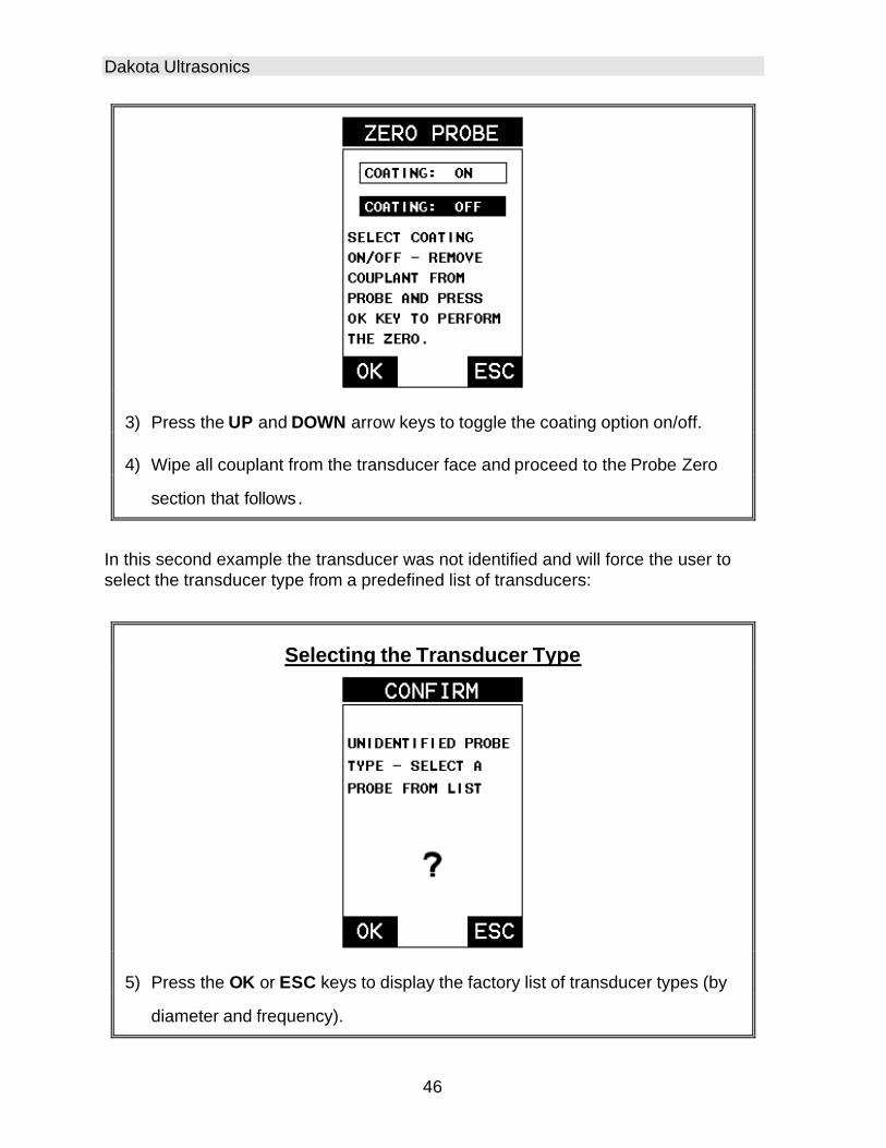
46
3) Press the UP and DOWN arrow keys to toggle the coating option on/off.
4) Wipe all couplant from the transducer face and proceed to the Probe Zero
section that follows.
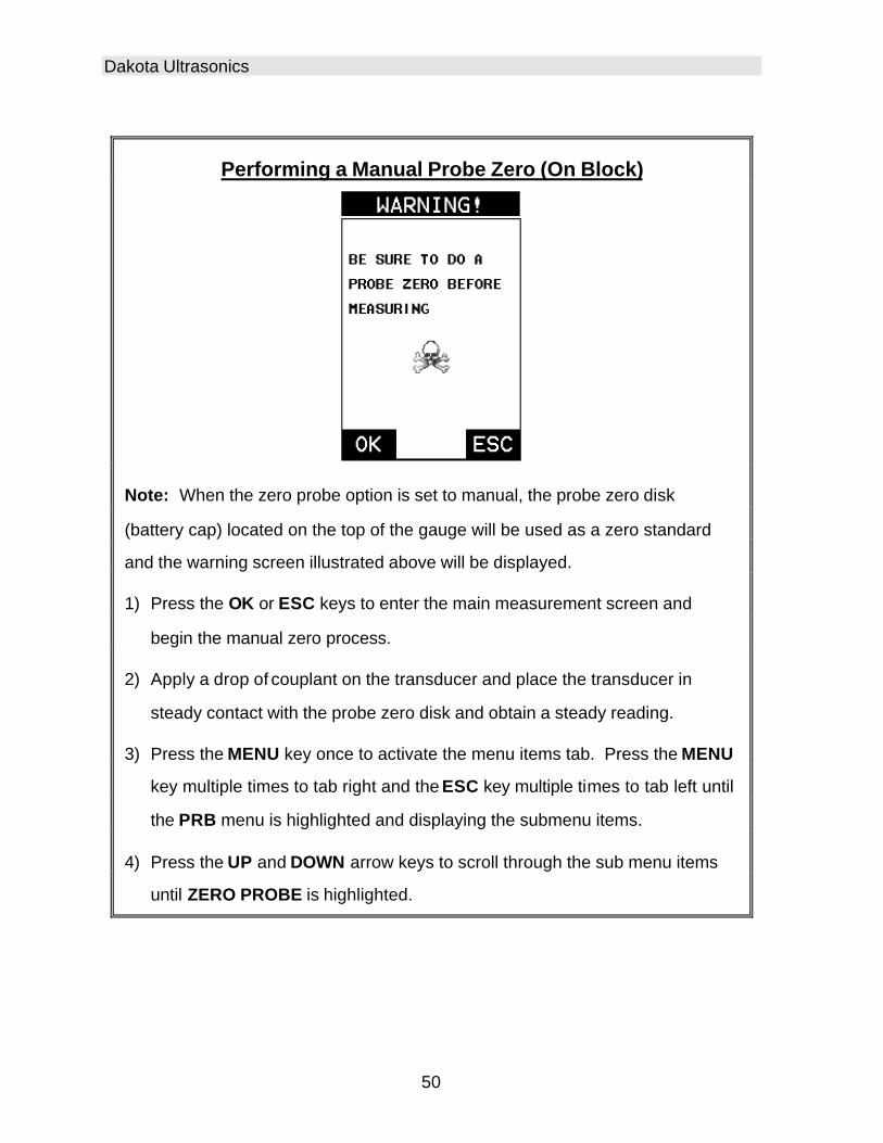
In this second example the transducer was not identified and will force the user to select the transducer type from a predefined list of transducers:
Selecting the Transducer Type
5) Press the OK or ESC keys to display the factory list of transducer types (by
diameter and frequency).

CMXDL+ High Performance Material & Coating Thickness Gauge
47
6) Press the UP and DOWN arrow keys to scroll through the transducer list
until the appropriate type is highlighted.
7) Press the ENTER key to select the transducer type and display overwrite
existing probe screen.
8) Press the OK key to overwrite the existing probe type with the newly
selected probe type. The zero probe screen will be displayed. Proceed to
the zero probe section that follows.

Dakota Ultrasonics
48
6.2 Probe zero The next step is to perform a probe zero. The zero function is a very important and necessary function that must be done prior to calibration. It should be done on a regular basis. In fact, the CMXDL+ has been programmed to force this issue at regular intervals during operation if it hasn’t been done. If the CMXDL+ is not zeroed correctly, all the measurements taken may be in error by some fixed value. When the CMXDL+ is using the auto zero (electronic zero), the CMXDL+ can be in any measurement mode. However, when the manual zero is being used, the CMXDL+ must be in pulse-echo mode in order to perform the zero. The CMXDL+ will also see to it that this occurs by simply forcing the gauge into this mode when zero. Therefore, if the CMXDL+ is in the echo-echo measurement mode and a manual zero is being performed, the CMXDL+ will put the gauge into pulse-echo mode automatically before performing the zero. While this is a very convenient feature of the CMXDL+, the user should be sure to check the measurement mode following calibration to be sure the CMXDL+ is in the desired mode. The following steps outline both of these techniques. The CMXDL+ is equipped with two zero options:
1) Off Block Zero (Automatic Probe Zero) – When this feature is enabled the CMXDL+ will do an electronic zero automatically, eliminating the need for a zero disk or block.
2) On Block Zero (Manual Probe Zero) – When this feature is enabled the transducer must be placed on the probe zero disk (battery cover located on the top of the unit.
Both zero procedures are outlined as follows:
Performing an Auto Probe Zero (Off Block)
Coating Probe Identified Coating Probe Not Identified

CMXDL+ High Performance Material & Coating Thickness Gauge
49
1) Be sure all couplant has been removed from the face of the transducer.
2) Press the OK key to perform the automatic probe zero, or ESC key to
cancel the zero operation.
Coating Probe Identified Coating Probe Not Identified
3) The screens illustrated above will be briefly displayed followed by the main
measurement screen. The CMXDL+ is ready to be calibrated.
Dakota Ultrasonics
50
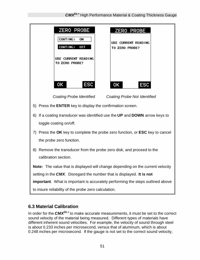
Performing a Manual Probe Zero (On Block)
Note: When the zero probe option is set to manual, the probe zero disk
(battery cap) located on the top of the gauge will be used as a zero standard
and the warning screen illustrated above will be displayed.
1) Press the OK or ESC keys to enter the main measurement screen and
begin the manual zero process.
2) Apply a drop of couplant on the transducer and place the transducer in
steady contact with the probe zero disk and obtain a steady reading.
3) Press the MENU key once to activate the menu items tab. Press the MENU
key multiple times to tab right and the ESC key multiple times to tab left until
the PRB menu is highlighted and displaying the submenu items.
4) Press the UP and DOWN arrow keys to scroll through the sub menu items
until ZERO PROBE is highlighted.
CMXDL+ High Performance Material & Coating Thickness Gauge
51
Coating Probe Identified Coating Probe Not Identified
5) Press the ENTER key to display the confirmation screen.
6) If a coating transducer was identified use the UP and DOWN arrow keys to
toggle coating on/off.
7) Press the OK key to complete the probe zero function, or ESC key to cancel
the probe zero function.
8) Remove the transducer from the probe zero disk, and proceed to the
calibration section.
Note: The value that is displayed will change depending on the current velocity
setting in the CMX. Disregard the number that is displayed. It is not
important. What is important is accurately performing the steps outlined above
to insure reliability of the probe zero calculation.
6.3 Material Calibration In order for the CMXDL+ to make accurate measurements, it must be set to the correct sound velocity of the material being measured. Different types of materials have different inherent sound velocities. For example, the velocity of sound through steel is about 0.233 inches per microsecond, versus that of aluminum, which is about 0.248 inches per microsecond. If the gauge is not set to the correct sound velocity,

Dakota Ultrasonics
52
all of the measurements the gauge makes will be erroneous by some fixed percentage. The One Point calibration is the simplest and most commonly used calibration method - optimizing linearity over large ranges. The Two Point calibration allows for greater accuracy over small ranges by calculating the probe zero and velocity. The CMXDL+ provides four simple methods for setting the sound-velocity outlined below:
Known Velocity If the material velocity is known, the user may wish to simply enter the velocity number into the CMXDL+, rather than have the CMXDL+ calculate the velocity value using a known thickness on a material sample. The steps for entering the velocity are outlined below:
Using a Known Material Velocity
1) Press the MENU key once to activate the menu items tab. Press the MENU
key multiple times to tab right and the ESC key multiple times to tab left until
the CAL menu is highlighted and displaying the submenu items.
2) Use the UP and DOWN arrow keys to scroll through the sub menu items
until VELOCITY is highlighted.

CMXDL+ High Performance Material & Coating Thickness Gauge
53
3) Press the ENTER key to display the Digits Edit Box.
4) Press the UP and DOWN arrow keys to scroll the highlighted value.
5) Press the LEFT and RIGHT arrow keys to scroll the digit locations.
6) Repeat steps 4 & 5 until the velocity number is correctly displayed.
7) Press the OK key to set the velocity and return to the menu screen, or ESC
to cancel entering the velocity.
8) Finally, press the MEAS key to return to the measurement screen and begin
taking readings.
Dakota Ultrasonics
54
Known Thickness Sometimes the sound velocity of a material is unknown. In this case a sample with one or two known thicknesses can be used to determine the sound velocity. As previously discussed, the CMXDL+ has a one or two point calibration option. The one point calibration option is most suited for linearity over large ranges, as noted above. The user should also consider calibrating on high side of the intended measurement range, when using the one point option, minimize overall error. For example, if the measurement range is .100” (2.54mm) to 1.0” (25.4mm), the user should calibrate on a known thickness sample close to 1.0” (25.4mm). Note: It’s always handy to carry a set of mechanical calipers to use in conjunction with the CMXDL+ for calibration in the field:
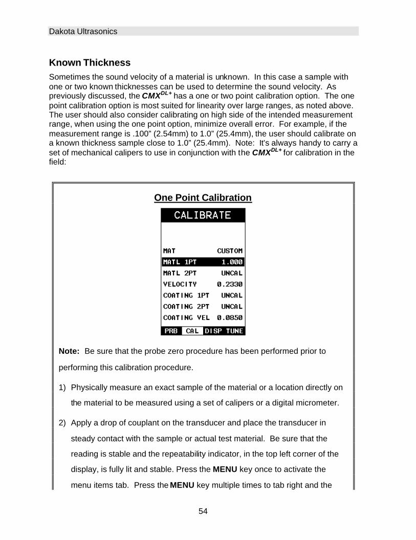
One Point Calibration
Note: Be sure that the probe zero procedure has been performed prior to
performing this calibration procedure.
1) Physically measure an exact sample of the material or a location directly on
the material to be measured using a set of calipers or a digital micrometer.
2) Apply a drop of couplant on the transducer and place the transducer in
steady contact with the sample or actual test material. Be sure that the
reading is stable and the repeatability indicator, in the top left corner of the
display, is fully lit and stable. Press the MENU key once to activate the
menu items tab. Press the MENU key multiple times to tab right and the

CMXDL+ High Performance Material & Coating Thickness Gauge
55
ESC key multiple times to tab left until the CAL menu is highlighted and
displaying the submenu items.
3) Use the UP and DOWN arrow keys to scroll through the sub menu items
until MATL 1PT is highlighted.
4) Press the ENTER key to display the Digits Edit Box.
5) Press the UP and DOWN arrow keys to scroll the highlighted value.
6) Press the LEFT and RIGHT arrow keys to scroll the digit locations.
7) Repeat steps 5 & 6 until the known thickness value is correctly displayed.
8) Press the OK key to calculate the velocity and return to the menu screen, or
ESC to cancel the one point calibration.
9) Finally, press the MEAS key to return to the measurement screen and begin
taking readings.
Note: CHECK YOUR CALIBRATION! Place the transducer back on the
calibration point. The thickness reading should now match the known
thickness. If the thickness is not correct, repeat the steps above.
At some point there may become a requirement for improved accuracy over a smaller measurement range. In this case, a two point calibration would be most suited for

Dakota Ultrasonics
56
the job. For example, if the measurement range was .080” (2.03mm) to .250” (6.35mm), the user would perform a one point calibration on a known thickness sample close to .250” (6.35mm), followed by a two point calibration close to .080” (2.03mm). When a two point calibration is performed, the CMXDL+ calculates the zero and the velocity. The following steps outline this procedure:
Two Point Calibration
1) Physically measure an exact sample of the material or a location directly on
the material to be measured using a set of calipers or a digital micrometer.
2) Apply a drop of couplant on the transducer and place the transducer in
steady contact with the sample or actual test material. Be sure that the
reading is stable and the repeatability indicator, in the top left corner of the
display, is fully lit and stable. Press the MENU key once to activate the
menu items tab. Press the MENU key multiple times to tab right and the
ESC key multiple times to tab left until the CAL menu is highlighted and
displaying the submenu items.
3) Use the UP and DOWN arrow keys to scroll through the sub menu items
until MATL 2PT is highlighted.
CMXDL+ High Performance Material & Coating Thickness Gauge
57
4) Press the ENTER key to display the Digits Edit Box.
5) Press the UP and DOWN arrow keys to scroll the highlighted value.
6) Press the LEFT and RIGHT arrow keys to scroll the digit locations.
7) Repeat steps 5 & 6 until the known thickness value is correctly displayed.
8) Press the OK key to calculate the velocity and return to the menu screen, or
ESC to cancel the one point calibration.
9) Finally, press the MEAS key to return to the measurement screen and begin
taking readings.
Note: CHECK YOUR CALIBRATION! Place the transducer back on the
calibration point. The thickness reading should now match the known
thickness. If the thickness is not correct, repeat the steps above.
Basic Material Type If the material velocity is unknown, and a sample thickness cannot be taken from the material, the user may opt to choose a basic material type from a list with approximate velocity values according to various material types. It’s important to note that these ve locities will not always be an exact representation of the material

Dakota Ultrasonics
58
being tested. Use these values only if a close approximation is acceptable. Follow the steps below to select a basic material type:
Selecting a Basic Material Type
1) Press the MENU key once to activate the menu items tab. Press the MENU
key multiple times to tab right and the ESC key multiple times to tab left until
the CAL menu is highlighted and displaying the submenu items.
2) Use the UP and DOWN arrow keys to scroll through the sub menu items
until MAT is highlighted.
3) Press the ENTER key to display the list of material types.

CMXDL+ High Performance Material & Coating Thickness Gauge
59
4) Press the UP and DOWN arrow keys to scroll through the material list until
the appropriate material is highlighted.
5) Press the ENTER key to overwrite the material type and display the menu
items with the new material type selected.
6) Finally, press the MEAS key to return to the measurement screen and begin
taking readings.
To calibrate the CMXDL+ for a specific type of coating using samples with known thicknesses, please refer to the chapter 9 – Pulse-Echo Coating (PECT) or Coating (CT) for a complete explanation of using the CMXDL+ for coating measurements.
60
CHAPTER SEVEN USING THE DISPLAY OPTIONS
A key feature of the CMXDL+ is the ability to toggle between four different display options; Digits, RF, RECT and B-Scan. All views provide a digital readout of base material and coating thickness measurements, while also displaying the alarm tolerances, if active. A key feature of the CMXDL+ is the waveform display. The waveform is a graphical representation of the sound reflections returning to the transducer. Consider standing at the base of a canyon and screaming “Hello There”. After a brief delay, you will here multiple echoes, “Hello There’s” repeated back to you. The waveform display shows the amplitude of the signal received on the vertical (Y) axis and time (shown in units of thickness) on the horizontal (X) axis. The waveform display is very useful for viewing and adjusting the location of the gates. The gates are typically used to eliminate potential surface noise by adjusting the starting point in single echo modes, for multi echo measurement modes, as well as to adjust the threshold (sensitivity) in either mode. The waveform display is also very useful for locating pits and internal flaws in materials. The B-Scan display is also very useful when scanning surfaces and viewing the cross section of the test material. It provides a convenient way of visually profiling, or drawing a picture of, the blind surfaces during a scan. The B-Scan display is also equipped with a scan bar representing the overall thickness. The scan bar gives the user a visual indication when a flaw or defect passed over during the scan process. The scan bar will deflect off of the defect and return back to the overall thickness. Visually, this is much easier to notice than watching for changes in the digital value displayed. The scan bar has also been included in the large digits display mode for the same purpose. Note: The following chapter outlines some of the fine adjustment features of the CMXDL+. The CMXDL+ has four different display options (RF A-Scan, Rectified A-Scan, B-Scan, and Large Digits). We’ll take a better look at these options in this chapter. Note: In order to recall and use the new adjustments made to the CMXDL+ at a later time, the user must save the modified settings in one of the setup locations prior to powering off the unit. Refer page 157 for more information on setups.

CMXDL+ High Performance Material & Coating Thickness Gauge
61
7.1 Display Views
DIGITS VIEW
DIGITS
The Digits view is a basic digital thickness gauge look and feel. The larger digits make it much easier for the operator to monitor the thickness readings. The Scan Bar has also been added to the Digits view to provide the user with yet another visual tool for easily monitoring changes in thickness readings due to internal flaws or defects. The following is a list of the viewable features on the display:
A. Repeatability/Stability Indicator – This indicator should be commonly used in conjunction with the digital thickness values displayed. When all the vertical bars are fully illuminated and the last digit on the digital thickness value is stable, the CMXDL+ is reliably measuring the same value 3 to 200 times per second, depending on which measurement mode and features are enabled.
B. Battery Icon – Indicates the amount of battery life the CMXDL+ has remaining. C. Velocity – The material velocity value the CMXDL+ is currently using or
calibrated for. Displayed in English or Metric units, depending on the what units the gauge is set for.
D. Feature Status Bar – Indicates the features currently enabled and in use in the following order:
• Measurement Mode (P-E, PECT, PETP, E-E, E-EV, COAT) • Differential Mode (ON/OFF) • High Speed Scan Mode (ON/OFF)

Dakota Ultrasonics
62
• Alarm Mode (ON/OFF/AUDIBLE) • Gain Setting (VLOW, LOW, MED, HI, VHI)
E. Digital Material Thickness Value – Extra large font size for viewing ease. F. Scan Bar – Another view of material thickness in a deflection style horizontal
bar. This is another visual tool that would enable the user the ability to see thickness changes during high speed scans from flaws and pits.
G. Units – The current measurement units being used (English, Metric). H. Coating Thickness Value – Displays the actual thickness of any coating
adhered to a metallic material surface (PECT Mode), or a coating adhered to a non-metallic surface (CT Mode).
I. Minimum Material Thickness – Part of the Alarm feature. Displays the minimum thickness value found during a scan.
J. Maximum Material Thickness – Part of the Alarm feature. Displays the maximum thickness value found during a scan.
B-Scan View
B-Scan The B-Scan displays a time based cross section view of test material. This view is commonly used to display the contour of the blind, or underside, surface of a pipe or tank application. It is very similar to a fish finder. If a flaw or pit is located during a scan, the B-Scan will draw the pit on the screen. The solid black rectangle in the diagram at location K represents the cross section, or side view of the material. The B-Scan view draws at a rate of 7 seconds per screen from right to left. Also notice at location K, the pits and corroded bottom surface of the material. It’s important to note that the measurement range on the display be set wide enough, so that the maximum thickness of the material can be viewed on the display. Using the diagram above, if the material thickness was actually 1.75”, the underside of the material would not be viewable according to the current range at 0.00” – 1.00”. All
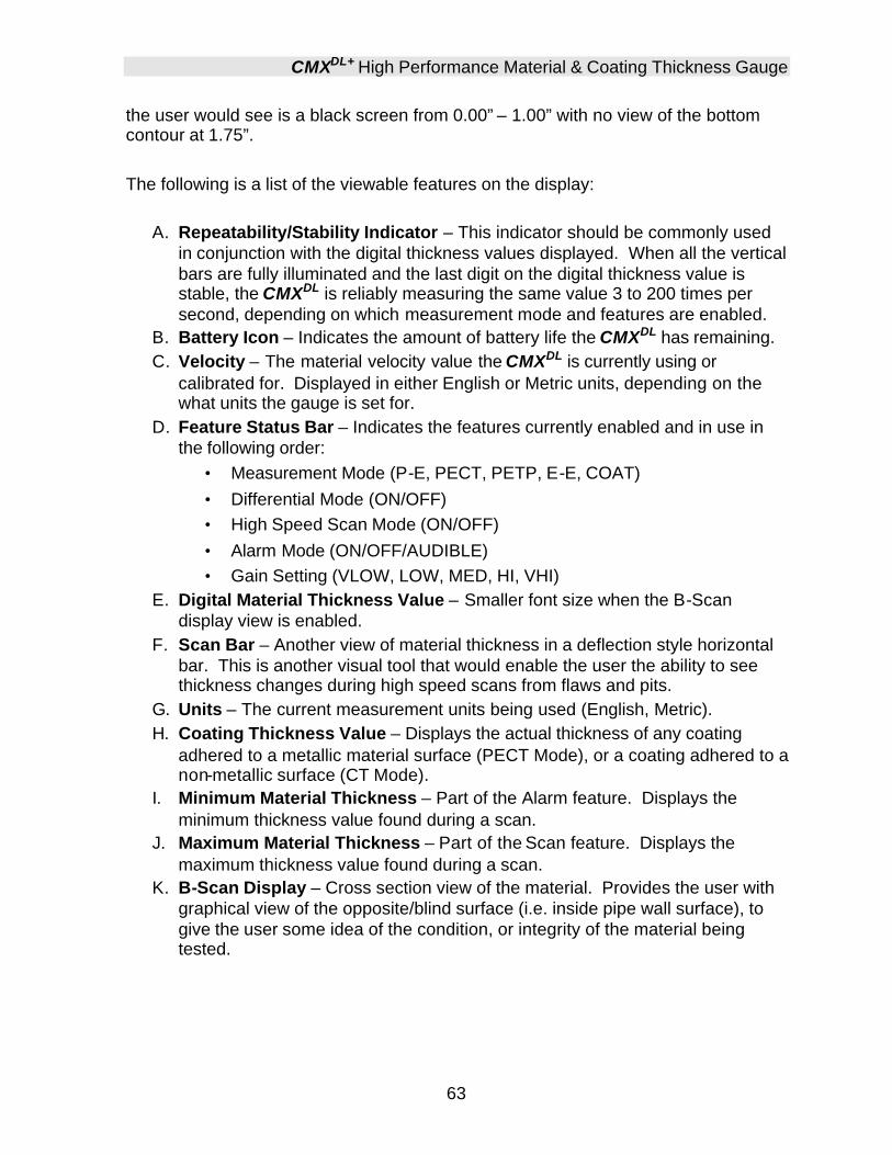
CMXDL+ High Performance Material & Coating Thickness Gauge
63
the user would see is a black screen from 0.00” – 1.00” with no view of the bottom contour at 1.75”. The following is a list of the viewable features on the display:
A. Repeatability/Stability Indicator – This indicator should be commonly used in conjunction with the digital thickness values displayed. When all the vertical bars are fully illuminated and the last digit on the digital thickness value is stable, the CMXDL is reliably measuring the same value 3 to 200 times per second, depending on which measurement mode and features are enabled.
B. Battery Icon – Indicates the amount of battery life the CMXDL has remaining. C. Velocity – The material velocity value the CMXDL is currently using or
calibrated for. Displayed in either English or Metric units, depending on the what units the gauge is set for.
D. Feature Status Bar – Indicates the features currently enabled and in use in the following order:
• Measurement Mode (P-E, PECT, PETP, E-E, COAT) • Differential Mode (ON/OFF) • High Speed Scan Mode (ON/OFF) • Alarm Mode (ON/OFF/AUDIBLE) • Gain Setting (VLOW, LOW, MED, HI, VHI)
E. Digital Material Thickness Value – Smaller font size when the B-Scan display view is enabled.
F. Scan Bar – Another view of material thickness in a deflection style horizontal bar. This is another visual tool that would enable the user the ability to see thickness changes during high speed scans from flaws and pits.
G. Units – The current measurement units being used (English, Metric). H. Coating Thickness Value – Displays the actual thickness of any coating
adhered to a metallic material surface (PECT Mode), or a coating adhered to a non-metallic surface (CT Mode).
I. Minimum Material Thickness – Part of the Alarm feature. Displays the minimum thickness value found during a scan.
J. Maximum Material Thickness – Part of the Scan feature. Displays the maximum thickness value found during a scan.
K. B-Scan Display – Cross section view of the material. Provides the user with graphical view of the opposite/blind surface (i.e. inside pipe wall surface), to give the user some idea of the condition, or integrity of the material being tested.
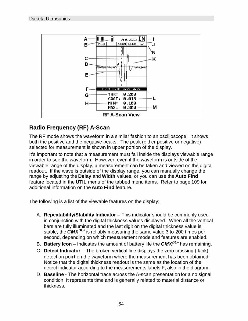
Dakota Ultrasonics
64
RF A-Scan View
Radio Frequency (RF) A-Scan The RF mode shows the waveform in a similar fashion to an oscilloscope. It shows both the positive and the negative peaks. The peak (either positive or negative) selected for measurement is shown in upper portion of the display. It’s important to note that a measurement must fall inside the displays viewable range in order to see the waveform. However, even if the waveform is outside of the viewable range of the display, a measurement can be taken and viewed on the digital readout. If the wave is outside of the display range, you can manually change the range by adjusting the Delay and Width values, or you can use the Auto Find feature located in the UTIL menu of the tabbed menu items. Refer to page 109 for additional information on the Auto Find feature. The following is a list of the viewable features on the display:
A. Repeatability/Stability Indicator – This indicator should be commonly used in conjunction with the digital thickness values displayed. When all the vertical bars are fully illuminated and the last digit on the digital thickness value is stable, the CMXDL+ is reliably measuring the same value 3 to 200 times per second, depending on which measurement mode and features are enabled.
B. Battery Icon – Indicates the amount of battery life the CMXDL+ has remaining. C. Detect Indicator – The broken vertical line displays the zero crossing (flank)
detection point on the waveform where the measurement has been obtained. Notice that the digital thickness readout is the same as the location of the detect indicator according to the measurements labels F, also in the diagram.
D. Baseline - The horizontal trace across the A-scan presentation for a no signal condition. It represents time and is generally related to material distance or thickness.

CMXDL+ High Performance Material & Coating Thickness Gauge
65
E. Gate – An electronic feature that allows the user to monitor signals inside the boundaries of the gate settings. The height of the gate from the baseline is known as the threshold, and controls the sensitivity of the reflections that trigger a detection from the opposite surface of the material.
F. Measurement Scale – Represents thickness values over a defined measurement range, and labeled at the calibrated hash marks on the display (X) axis.
G. Digital Material Thickness Value – The thickness of the base material. H. Minimum Thickness Value – Dynamically updates the value during a scan,
and displays the minimum thickness value found. Note: Only visible when high speed scan mode is enabled.
I. Units – The current measurement units being used (English, Metric). J. Velocity – The material velocity value the CMXDL is currently using or
calibrated for. Displayed in either English or Metric units, depending on what units the gauge is set for.
K. RF waveform – The sine wave created by the reflected sound, or oscillation, from the material being measured. The both the positive and negative half cycles (full cycles) are displayed.
L. Coating Thickness Value – Displays the actual thickness of any coating adhered to a metallic material surface (PECT Mode), or a coating adhered to a non-metallic surface (CT Mode).
M. Minimum Thickness Value – Dynamically updates the value during a scan, and displays the minimum thickness value found. Note: Only visible when high speed scan mode is enabled.
N. Feature Status Bar - Indicates the features currently enabled and in use in the following order:
• Measurement Mode (P-E, PECT, PETP, E-E, COAT) • Differential Mode (ON/OFF) • High Speed Scan Mode (ON/OFF) • Alarm Mode (ON/OFF/AUDIBLE) • Gain Setting (VLOW, LOW, MED, HI, VHI)

Dakota Ultrasonics
66
RECT A-Scan View
Rectified (RECT) A-Scan The RF mode shows the waveform in a similar fashion to an oscilloscope. It shows both the positive and the negative peaks. The peak (either positive or negative) selected for measurement is shown in upper portion of the display. It’s important to note that a measurement must fall inside the displays viewable range in order to see the waveform. However, even if the waveform is outside of the viewable range of the display, a measurement can be taken and viewed on the digital readout. If the wave is outside of the display range, you can manually change the range by adjusting the Delay and Width values, or you can use the Auto Find feature located in the UTIL menu of the tabbed menu items. Refer to page 109 for additional information on the Auto Find feature. The following is a list of the viewable features on the display:
A. Repeatability/Stability Indicator – This indicator should be commonly used in conjunction with the digital thickness values displayed. When all the vertical bars are fully illuminated and the last digit on the digital thickness value is stable, the CMXDL+ is reliably measuring the same value 3 to 200 times per second, depending on which measurement mode and features are enabled.
B. Battery Icon – Indicates the amount of battery life the CMXDL+ has remaining. C. Detect Indicator – The broken vertical line displays the zero crossing (flank)
detection point on the waveform where the measurement has been obtained. Notice that the digital thickness readout is the same as the location of the detect indicator according to the measurements labels F, also in the diagram.
D. Baseline - The horizonta l trace across the A-scan presentation for a no signal condition. It represents time and is generally related to material distance or thickness.

CMXDL+ High Performance Material & Coating Thickness Gauge
67
E. Gate – An electronic feature that allows the user to monitor signals inside the boundaries of the gate settings. The height of the gate from the baseline is known as the threshold, and controls the sensitivity of the reflections that trigger a detection from the opposite surface of the material.
F. Measurement Scale – Represents thickness values over a defined measurement range, and labeled at the calibrated hash marks on the display (X) axis.
G. Digital Material Thickness Value – The thickness of the base material. H. Minimum Thickness Value – Dynamically updates the value during a scan,
and displays the minimum thickness value found. Note: Only visible when high speed scan mode is enabled.
I. Units – The current measurement units being used (English, Metric). J. Velocity – The material velocity value the CMXDL+ is currently using or
calibrated for. Displayed in either English or Metric units, depending on what units the gauge is set for.
K. RECT waveform – The half cycle, either positive or negative, of the RF sine wave, created by the reflected sound, or oscillation, from the material being measured. This view is typically considered as “flaw” view.
L. Coating Thickness Value – Displays the actual thickness of any coating adhered to a metallic material surface (PECT Mode), or a coating adhered to a non-metallic surface (CT Mode).
M. Minimum Thickness Value – Dynamically updates the value during a scan, and displays the minimum thickness value found. Note: Only visible when high speed scan mode is enabled.
N. Feature Status Bar - Indicates the features currently enabled and in use in the following order:
• Measurement Mode (P-E, PECT, PETP, E-E, COAT) • Differential Mode (ON/OFF) • High Speed Scan Mode (ON/OFF) • Alarm Mode (ON/OFF/AUDIBLE) • Gain Setting (VLOW, LOW, MED, HI, VHI)

Dakota Ultrasonics
68
7.2 Changing Display Options The following procedure outlines how to select or toggle display options:
Changing Display Options
Grayscale VGA Color VGA
1) Press the MENU key once to activate the menu items tab. Press the MENU
key multiple times to tab right, and the ESC key multiple times to tab left,
until the DISP menu is highlighted and displaying the submenu items.
2) Use the UP and DOWN arrow keys to scroll through the sub menu items
until VIEW is highlighted.
3) Use the LEFT and RIGHT arrow keys to scroll the view options. Once the
appropriate view is displayed, press the MEAS key to return to the
measurement screen and begin taking measurements.

CMXDL+ High Performance Material & Coating Thickness Gauge
69
7.3 Adjusting the display This section will cover the procedures for adjusting the viewable range, or area, of the display, in terms of thickness. A basic overview of this section would be as follows: Suppose we had a 50” widescreen television set. Assume that you’re watching the television for rest of this explanation. The left side of the television screen is considered the Delay for all view options other than B-Scan. In B-Scan view, it’s called B-Start. Therefore, Delay (B-Start) are identical, with the exception of the terminology used, and represent the left side of the television screen. The right side of the television screen is considered the Range + Delay, in all view options with the exception of B-Scan, once again. In B-Scan view, it would be considered B-Depth + B-Start. Therefore, the following should be considered: Delay (B-Start) + Range (B-Depth) = right side of the screen, depending on what view option is active. Now, by adjusting the left and right side of the television screen, to control the viewable area/range, we can zoom in and out of any part of the 50” screen we’d like, and focus on only the specific areas of the screen we need to . Therefore, if I am measuring a part, and am only interested in viewing the thickness range/area from .500” – 1.0”, and I’d like to zoom in a bit to get a close up look at things, I’d set my Delay (B-Start) to .500” and my Range (B-Depth) to .500”. This would make the left side of my screen start at .500”, and the right side of the screen at 1.0”.
Setting the Delay (B-Start) The Delay (B-Start) represents the left side of the display, and can be adjusted to start at any thickness value within the overall range of the CMXDL+. The value the Delay (B-Start) is set too, is the minimum thickness value that will be displayed on the screen. Note: Once the delay is set, it will remain the same for the views: Digits, RF, RECT. However, in B-Scan view, the B-Start is an independent setting from Delay, and allow the user to store two independent settings respectively. The procedures to adjust the Delay (B-Start) are outlined below:
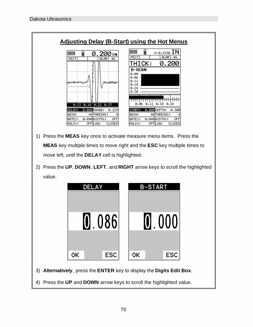
Dakota Ultrasonics
70
Adjusting Delay (B-Start) using the Hot Menus
1) Press the MEAS key once to activate measure menu items. Press the
MEAS key multiple times to move right and the ESC key multiple times to
move left, until the DELAY cell is highlighted.
2) Press the UP, DOWN, LEFT, and RIGHT arrow keys to scroll the highlighted
value.
3) Alternatively , press the ENTER key to display the Digits Edit Box.
4) Press the UP and DOWN arrow keys to scroll the highlighted value.

CMXDL+ High Performance Material & Coating Thickness Gauge
71
5) Press the LEFT and RIGHT arrow keys to scroll the digit locations.
6) Repeat steps 4 & 5 until the DELAY value is correctly displayed.
7) Press the OK key to return to the measurement screen, or ESC to cancel
entering the DELAY.
8) Finally, press the MEAS key to return to the measurement screen and begin
taking readings.
Adjusting the Range (B-Depth) Once again, just to reiterate, the Range (B-Depth) + Delay (B-Start) equals the right side of the screen. Therefore, the Range (B-Depth) is the overall area, from the delay, that will be viewable on the screen. The CMXDL+ digitizer will round up from the Range (B-Depth) that’s entered. Therefore, if the Range (B-Depth) is set at 1.0”, the digitizer will round this value up to the next adjustment available. The procedures to adjust the overall thickness range viewed Range (B-Depth) are outlined below:
Adjusting the Range (B-Depth) using the Hot Menus
1) Press the MEAS key once to activate measure menu items. Press the
MEAS key multiple times to move right and the ESC key multiple times to
move left, until the WIDTH cell is highlighted.

Dakota Ultrasonics
72
2) Press the UP, DOWN, LEFT, and RIGHT arrow keys to scroll the highlighted
value.
3) Alternatively , press the ENTER key to display the Digits Edit Box.
4) Press the UP and DOWN arrow keys to scroll the highlighted value.
5) Press the LEFT and RIGHT arrow keys to scroll the digit locations.
6) Repeat steps 4 & 5 until the WIDTH value is correctly displayed.
7) Press the OK key to return to the measurement screen, or ESC to cancel
entering the WIDTH.
8) Finally, press the MEAS key to return to the measurement screen and begin
taking readings.
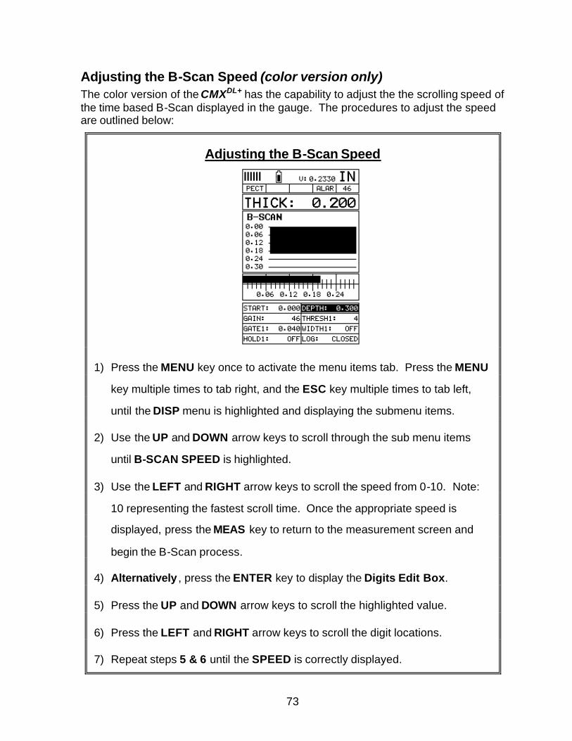
73
Adjusting the B-Scan Speed (color version only) The color version of the CMXDL+ has the capability to adjust the the scrolling speed of the time based B-Scan displayed in the gauge. The procedures to adjust the speed are outlined below:
Adjusting the B-Scan Speed
1) Press the MENU key once to activate the menu items tab. Press the MENU
key multiple times to tab right, and the ESC key multiple times to tab left,
until the DISP menu is highlighted and displaying the submenu items.
2) Use the UP and DOWN arrow keys to scroll through the sub menu items
until B-SCAN SPEED is highlighted.
3) Use the LEFT and RIGHT arrow keys to scroll the speed from 0-10. Note:
10 representing the fastest scroll time. Once the appropriate speed is
displayed, press the MEAS key to return to the measurement screen and
begin the B-Scan process.
4) Alternatively , press the ENTER key to display the Digits Edit Box.
5) Press the UP and DOWN arrow keys to scroll the highlighted value.
6) Press the LEFT and RIGHT arrow keys to scroll the digit locations.
7) Repeat steps 5 & 6 until the SPEED is correctly displayed.

Dakota Ultrasonics
74
8) Press the OK key to set the speed and return to the DISP menu., followed
by pressing the MEAS key to begin the B-Scan process.
9) Finally, press the MEAS key to return to the measurement screen and begin
the scanning process.
7.4 Gain The gain, or amplification of the return echoes, can be adjusted in the CMXDL+ to accommodate a variety of applications. The setting of the gain is crucial in order to obtain valid readings during the measurement process. Too much gain may result in erroneous measurements, by detecting on noise rather than the actual material back wall itself. Not enough gain may result in intermittent detection. It may also result in lack of detection on internal flaws, pits, or porosity. The gain can easily be compared to the volume control of a home stereo system. If you turn it up too much, you can’t hear the music clearly. If it’s turned down too much, you can’t hear it at all. The CMXDL+ has 110dB gain range, but has been limited to a 60dB gain range (-10 to 50 dB), for thickness gauge applications. The common starting point for standard thickness gauge applications is 46dB. This feature is used to increase/decrease the power or amplitude of the signal. When used in conjunction with the attenuator feature, it has a limited overall gain range of -30dB to 70dB. The gain can be adjusted to accommodate a variety of material types. Having this feature available, provides the user with a great deal of flexibility. Some applications may require the lower or higher gain settings. When? The low settings may be necessary for noisy or granular cast materials. How do I know when to lower the gain? If the reading becomes sporadic and won’t settle down or resolve on a thickness value, the user can assume that the material is either very noisy aluminum, or granular cast iron. This would be a good time to change the CMXDL+ to lower gain setting and see if the reading settles down and become stable. How do I know when to increase the gain? Often times the user will be trying to measure a material that is hard to penetrate or pass sound through. This may be due to the material type, or overall thickness of the material. When a material is hard to pass sound through because of the thickness or general make-up, it would be a good time to consider increasing the CMXDL+ to a higher gain setting. Another example might be the need to increase overall sensitivity for locating fine pits or flaws. In any case, the adjustable gain feature offers the user some additional options to resolve and overcome application issues.

CMXDL+ High Performance Material & Coating Thickness Gauge
75
Note: When the echo-echo thru-paint, o r echo-echo-verify measurement modes are selected, the manual gain feature is disabled and grayed out in the menu items. In this mode, the CMXDL+ switches to an automatic gain mode (AGC) that optimizes the gain setting automatically in the hardware of the CMXDL+. The procedures to adjust the Gain are outlined below:
Adjusting the Gain using the Hot Menus
1) Press the MEAS key once to activate measure menu items. Press the
MEAS key multiple times to move right, and the ESC key multiple times to
move left until the GAIN cell is highlighted.
2) Press the UP, DOWN, LEFT, and RIGHT arrow keys to scroll the highlighted
value.

Dakota Ultrasonics
76
3) Alternatively, press the ENTER key to display the Digits Edit Box.
4) Press the UP and DOWN arrow keys to scroll the highlighted value.
5) Press the LEFT and RIGHT arrow keys to scroll the digit locations.
6) Repeat steps 4 & 5 until the GAIN value is correctly displayed.
7) Press the OK key to return to the measurement screen, or ESC to cancel
entering the GAIN.

CMXDL+ High Performance Material & Coating Thickness Gauge
77
The user can also access and adjust the gain from the tabbed menus. However, this method is more tedious than making the adjustments using the Hot Menus. The procedure using the tabbed menus is outlined below:
Adjusting the Gain using the Tabbed Menus
1) Press the MENU key once to activa te the menu items tab. Press the
MENU key multiple times to tab right, and the ESC key multiple times to tab
left, until the TUNE menu is highlighted and displaying the submenu items.
2) Use the UP and DOWN arrow keys to scroll through the sub menu items
until GAIN is highlighted.
3) Press the LEFT and RIGHT arrow keys to scroll the value. When the
correct Gain is being displayed, proceed to step 8 .
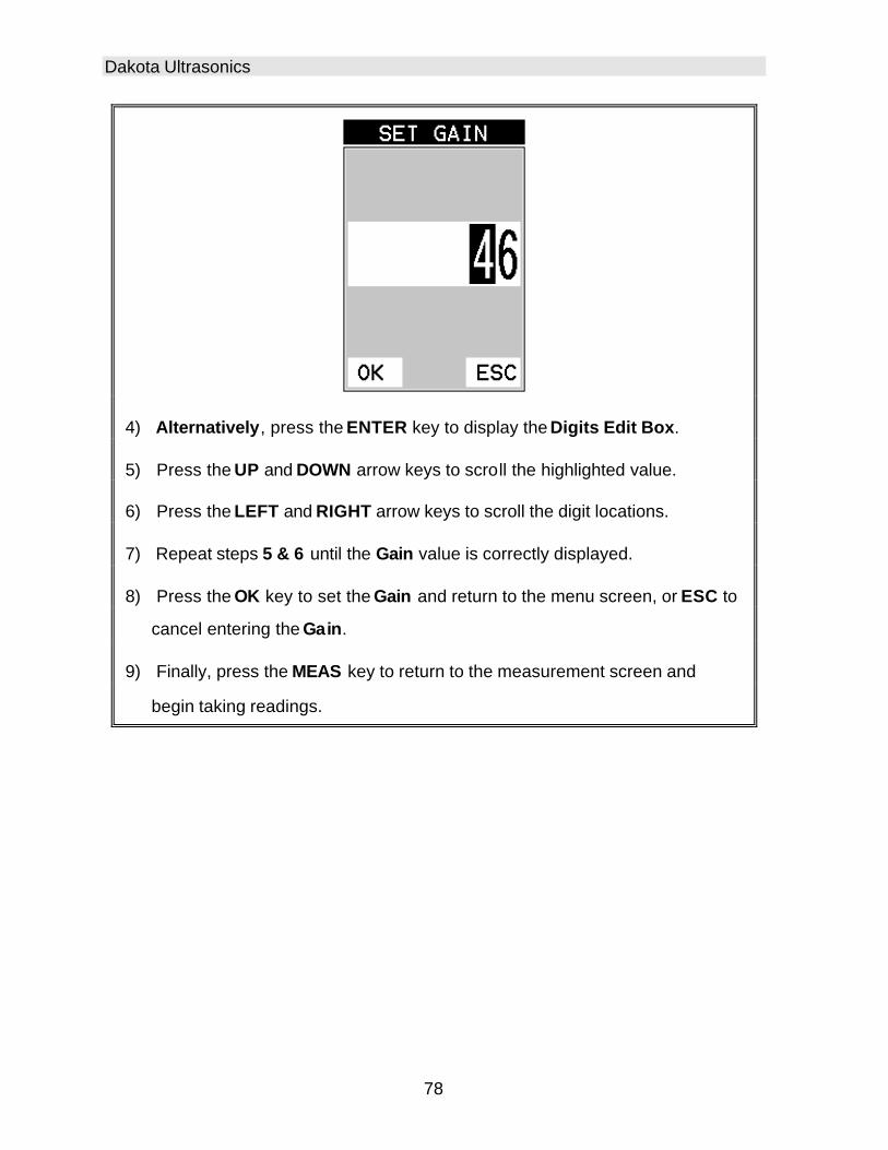
Dakota Ultrasonics
78
4) Alternatively, press the ENTER key to display the Digits Edit Box.
5) Press the UP and DOWN arrow keys to scroll the highlighted value.
6) Press the LEFT and RIGHT arrow keys to scroll the digit locations.
7) Repeat steps 5 & 6 until the Gain value is correctly displayed.
8) Press the OK key to set the Gain and return to the menu screen, or ESC to
cancel entering the Gain.
9) Finally, press the MEAS key to return to the measurement screen and
begin taking readings.

CMXDL+ High Performance Material & Coating Thickness Gauge
79
7.5 Threshold The Threshold is the level (sensitivity) of the signal amplitude required to trigger the thickness reading. This level can be used in conjunction with the gain. Example: suppose the user can visually see a potential flaw on the display, but the CMXDL+ is not detecting on the flaw because the Gain is too low, or the Threshold to high. The Threshold level can be decreased (lower sensitivity) in order to detect signals with lower amplitudes. This will allow the amplitude from the reflection of the flaw to reach and exceed the Threshold level, and enable the CMXDL+ to detect on the flaw or defect. This can also be accomplished by increasing the Gain, allowing the signal to exceed the current Threshold level. Lowering the Threshold (increases sensitivity), and raising the Threshold decreases the sensitivity respectively. The CMXDL+ is equipped with 3 independent gates, each with an adjustable threshold level. All three gates can be enabled in any of the pulse echo modes, and in echo-echo verify mode, and the thresholds set at varying levels of sensitivity. The allows the user to create a pseudo make-shift “time corrected gain” function, by increasing the sensitivity of each gate at different thickness values. A visual example would be an upside down stair case, where each step represented a separate gate, for a specific thickness range. The procedures to adjust the Thresholds are outlined below:
Adjusting the Thresholds using the Hot Menus
1) Press the MEAS key once to activate measure menu items. Press the
MEAS key multiple times to move right and the ESC key multiple times to
move left, until the THRESH(1-3) cell is highlighted.

Dakota Ultrasonics
80
2) If the correct THRESHOLD is displayed, press the UP, DOWN, LEFT, and
RIGHT arrow keys to scroll the highlighted value.
3) Alternatively, if the correct Threshold is not being displayed, press the
ENTER key to display the List Box.
4) Use the UP and DOWN arrow keys to scroll through the List Box items
until the correct THRESHOLD is highlighted.
5) Press the MEAS key to return to the measure screen and Hot Menu items.
6) Press the UP, DOWN, LEFT, and RIGHT arrow keys to scroll the highlighted
value.
7) Repeat steps 3-6 until all the THRESH values are correctly adjusted.
The user can also access and adjust the Threshold from the tabbed menus. However, this method is more tedious than making the adjustments using the Hot Menus. The procedure for using the tabbed menus is outlined below:
Adjusting the Thresholds using the Tabbed Menus

CMXDL+ High Performance Material & Coating Thickness Gauge
81
1) Press the MENU key once to activate the menu items tab. Press the
MENU key multiple times to tab right, and the ESC key multiple times to tab
left, until the GT1 menu is highlighted and displaying the submenu items.
2) Use the UP and DOWN arrow keys to scroll through the sub menu items
until THRESHOLD1 is highlighted.
3) Press the LEFT and RIGHT arrow keys to scroll the value. When the
correct threshold is being displayed, proceed to step 8 .
4) Alternatively, press the ENTER key to display the Digits Edit Box.
5) Press the UP and DOWN arrow keys to scroll the highlighted value.
6) Press the LEFT and RIGHT arrow keys to scroll the digit locations.
7) Repeat steps 5 & 6 until the Threshold number is correctly displayed.
8) Press the OK key to set the Threshold and return to the menu screen, or
ESC to cancel entering the Threshold.
9) Repeat steps 1-8 to set any additional Threshold level.

Dakota Ultrasonics
82
10) Finally, press the MEAS key to return to the measurement screen and
begin taking readings.

CMXDL+ High Performance Material & Coating Thickness Gauge
83
7.6 Understanding the features of the Gate Important: It is recommended to spend some time in this section. The sections that follow are procedures for using the features associated with the Gates, in some way. There are 3 gates in the CMXDL+, and as a result, operating and setting them up can become somewhat convoluted, to say the least. However, a thorough understanding of the functionality presented in this section, will reveal how easy they actually are to operate overall. The following diagrams illustrate the features of all 3 gates, according to the measurement mode selected: Note: This is a general overview and should be referred to in conjunction with the detailed feature sections that follow.
Modes # Gates Gate # Start HoldOff Width Threshold
PE 1,2,or 3 1 v v v2 v v3 v v
PECT 1,2,or 3 1 v v v2 v v3 v v
PETP 1,2,or 3 1 v v v2 v v3 v v
EE 2 1 v v2 v v v3
EEV 3 1 v v2 v v3 v v
CT None None None None None None Diag. 1 Gate Features vs Modes
In diagram 1, the gates have been associated with the measurement modes, along with the features available to every gate. For example, echo-echo mode (EE) has 2 gates available, while echo-echo verify (EEV) has 3. These gates have been designed to work in order, from 1 to 3, and cannot be used any other way. Therefore, the user must be using gate 2 before they can activate and use gate 3. Note: Gate 1 is on at all times, as a gate must be activated to get a measurement. Each gate has a given set of features to fine adjust the settings of the gate. Let’s have a look at the feature set: Start (Gate1): This feature is only available to gate 1, and determines the start value of the left side of the gate. For example, if there’s a great deal of noise from the initial

Dakota Ultrasonics
84
pulse, or in the material, the gate can be moved to the right of the noise and block the unwanted noise. Gates 2 and 3 will automatically start from the end of gate 1, or from a detection found inside of the boundaries of gate 1. Therefore, we use a hold-off delay as a start feature for gates 2 and 3. See Diagram 2. Hold-Off: The hold-off is the starting point of the left side of gates 2 & 3, and is used only if a detection is found inside the previous gate. It should be considered a delay from the detection point of the previous gate. When the hold-off is off, or 0, the gate will start at the point of detection from the previous gate. As the value of the hold-off is increased, it is further delaying the start of the gate to the right of the detection of the previous gate. Note: Although we’ve used the terminology of hold-off for gate 3, it is actually a “hold-back” from the detection of the second echo. Therefore, as the value is increased, the “hold -back” moves closer to the second detection. Just the opposite of the operation of gate 2 hold-off. See diagram 2. Width: The width determines the physical length of the gate. Therefore, the width – start (hold-ff) equals the length of the gate, as the start (hold -off) value is not equal to zero. If no detection is located inside the boundaries of a gate, the width value is used to start the next available gate. Key point: When the width is activated for a gate, giving it a value, the next available gate is also activated. Therefore, activating width1 of gate1, activates gate2, and activating width2 of gate2, activates gate3. See diagram 2. Thresh: The threshold controls the level of sensitivity of the signal amplitude required to trigger a detection, or measurement. It is represented by the distance from the baseline, and displayed as the vertical position of a gate. The further the vertical position is from the baseline, the less sensitive the threshold is, and visa versa. This allows the user to have further control over the size of the defects considered critical, or the ability to get a detection, from the opposite surface, in very attenuative materials. This feature is used in conjunction with gain. Increasing the threshold has a similar effect of decreasing the gain, and visa versa.

CMXDL+ High Performance Material & Coating Thickness Gauge
85
Activating the gates: • Automatically: The gates are automatically activated, when a measurement
mode is selected. Gate1 is active in all measurement modes. These modes have been internally setup at the Dakota factory. Therefore, if the user selects the Thru Coat (E-E) option, an internal setup will be loaded, and 2 gates will automatically be activated. This setup will work fine for the majority of all common applications. The user has the ability to fine adjust the gates settings, which will be further explained in the sections that follow.
• Manually: The gates can also be activated manually by using the Hot or
Tabbed menus. For example: If any of the pulse echo modes (PE, PECT, PETP), shown in diagram 1, have been selected, only gate 1 will have been activated from the factory setup. However, the user may have a requirement to activate and utilize more than one gate, depending on the application.
Tabbed Menu Hot Menu

Dakota Ultrasonics
86
7.7 Gates The CMXDL+ is equipped with 3 gates, as explained in the previous section. One gate is active at all times in every measurement mode, with the exception of coating mode. These gates are full featured and completely adjustable. They can be fine tuned by the user to accommodate a variety of application scenarios. Diagram 1 in the previous section outlines the gates and features available for all measurement modes. Refer to the previous section for additional information. These features are described in more detail below: Note: In order to adjust the gates they must be activated. The gates are automatically activated depending upon the measurement mode selected. If a gate is inactive, it will be grayed out in the hot and tabbed menus. The explanations that follow, assume that the proper measurement mode has been selected. Refer to page 41 for more information on selecting measurement modes. Gate 1 Is used in all measurement modes, and has the following features assigned to it; start, width, and threshold. A gate can be used to overcome a great deal of application scenarios. Surface noise, for instance, close to the initial pulse can cause the erroneous measurements as the transducer receives reflections from the noise. By adjusting the start position of the gate, the noise can be blocked and eliminated. This is typical in aluminum, stainless steel, and titanium. This can also be a function of using a low frequency transducer, which are known to be inherently noisy off the initial pulse. The start feature of the gate is also used in multiple echo modes to control measurements between 2 or more echoes. As we saw in previous section, the threshold can be used to control the sensitivity level, and used in combination with the width, control the sensitivity over a specific range. Gate 2 & 3 These gate options will most commonly be used for multiple echo measurement modes, to measure between 2 or more echoes ( E-E and E-EV). They are also handy to use in a stand pulse echo mode, to create a pseudo time corrected gain feel. As the thickness of the material increases, the signal amplitude of the reflection decreases. Why not just turn up the gain? Well, this is certainly something to consider, but is not always the best answer. As the gain is increased, the noise level is also increased. At some point, increasing the gain provides little or no benefit to the quality of the signal, and the additional noise introduced makes things worse. By activating another gate, optimizing the gain level, setting the thresholds, and adjusting the widths of the gates to cover specific thickness ranges, a tough application might not be so bad after all. These gates have the following features set assigned to them; holdoff (delay), width, and threshold.

CMXDL+ High Performance Material & Coating Thickness Gauge
87
Example of Surface or Transducer Noise
Noise Blocked
The diagrams above illustrate a typical surface noise condition. Refer to the Noise diagram: (A) refers to the noise in front of the actual back wall signal (C). Notice the start position of the gate. As a result, the CMXDL+ is detecting on the noise (A) as shown at point (B). However, the true measurement should be taken at point (C). Given the start, threshold, and gain levels, the amplitude from the noise is sufficient enough to cause the CMXDL+ to detect, or measure the noise rather than the true back wall thickness (C). Therefore, the CMXDL+ is making an incorrect reading at point (B). Now refer to the Blocked diagram. The horizontal line at the top of (D), is GATE1. The start of GATE1 has been moved just beyond the noise (A) to block the noise and detect on the correct signal (C). Note: the CMXDL+ will only detect on signals that are located inside the dimensions of GATE1 (B). Therefore, the CMXDL+ cannot see (A) at all, with respect to the starting point of (B). Also notice, the position of the threshold level with respect to the baseline (D), which represents the sensitivity setting of the threshold. Extreme sensitivity is indicated by the bottom of the range (D) at the baseline, and less sensitivity indicated by the top of the range at (D). Therefore, the vertical height of GATE1 from the baseline, is the threshold level. The threshold level can be increased to decrease sensitivity, or visa versa. If the threshold level was increased in the Noise diagram, so that the vertical position of GATE1 was higher than the amplitude of the noise (A), the CMXDL+ would have detected on the true back wall (C). Alternatively, if the gain level was decreased, the signal amplitude of the noise (A) would have decreased below the threshold level, and the CMXDL+ would have also detected the true back wall (C). This example brings all the fine adjustments into consideration, and demonstrates the versatility of having a fully functional scope rather than a basic digital thickness gauge.

Dakota Ultrasonics
88
The procedures to adjust all of the features associated with the Gates are outlined below: Note: This is a combined procedure that works the same for any of the features associated with the gates, regardless of which feature and gate number that is being adjusted. Therefore (? ) = Gate1, Hold-Off, and Width respectively . Finally, the illustrations may not be applicable to the exact feature being adjusted, but the concepts relevant.
Adjusting the Features of the Gates Using the Hot Menus
Gate Holdoff ‘s Width’s
1) Press the MEAS key once to activate measure menu items. Press the
MEAS key multiple times to move right and the ESC key multiple times to
move left, until the (? ) cell is highlighted.
2) If the correct (? ) is displayed, press the UP, DOWN, LEFT, and RIGHT
arrow keys to scroll the highlighted value.
3) Alternatively, if the correct (? ) is not being displayed, press the ENTER
key to display the List Box.

CMXDL+ High Performance Material & Coating Thickness Gauge
89
4) Use the UP and DOWN arrow keys to scroll through the List Box items
until the correct (? ) is highlighted.
5) Press the MEAS key to return to the measure screen and Hot Menu items.
6) Press the UP, DOWN, LEFT, and RIGHT arrow keys to scroll the highlighted
value.
7) Repeat steps 3-6 until all the (? ) values are correctly adjusted.
The user can also access and adjust the (? ) from the tabbed menus. However, this method is more tedious than making the adjustments using the Hot Menus. The procedure for using the tabbed menus is outlined below:
Adjusting the Features of the Gates using the Tabbed Menus
1) Press the MENU key once to activate the menu items tab. Press the
MENU key multiple times to tab right, and the ESC key multiple times to tab
left, until the (? ) menu is highlighted and displaying the submenu items.
2) Use the UP and DOWN arrow keys to scroll through the sub menu items
until (? ) is highlighted.
3) Press the LEFT and RIGHT arrow keys to scroll the value. When the
correct (? ) is being displayed, proceed to step 8.

Dakota Ultrasonics
90
4) Alternatively, press the ENTER key to display the Digits Edit Box.
5) Press the UP and DOWN arrow keys to scroll the highlighted value.
6) Press the LEFT and RIGHT arrow keys to scroll the digit locations.
7) Repeat steps 5 & 6 until the (? ) number is correctly displayed.
8) Press the OK key to set the (? ) and return to the menu screen, or ESC to
cancel entering the (? ).
9) Repeat steps 1-8 to set any additional (? ) level.
10) Finally, press the MEAS key to return to the measurement screen and
begin taking readings.

91
CHAPTER EIGHT THRU PAINT MEASUREMENT TECHNIQUE
8.1 Introduction to Thru Paint Measurement The principle behind thru paint measurement is by measuring the time between two backwall echoes returning from the test material. Since both of these backwall echoes travel the same path through the paint or coating, the thickness of the coating is subtracted out of the measurement so that only the actual material thickness can be measured. This feature saves the user a great deal of time scraping and removing the coating from tanks and pipes during the inspection process. The CMXDL+ also has a special echo-echo verify option, or triple echo mode. This measurement mode is identical to the echo-echo mode described above, with an additional third echo measurement performed to verify the measurement between the first 2 echoes. By doing this, the CMXDL+ can confirm that a peak jump has not occurred, and the measurement made is stable and correct. This mode is only suitable for thin materials and coatings, as the ability to achieve 3 reflections is not always possible. The primary purpose of thru paint measurement is to determine actual or overall material thickness by eliminating the coating thickness. Thru paint mode cannot be used for flaw or pit detection. Therefore, inspectors may need to use echo-echo thru paint mode in conjunction with the standard pulse-echo flaw detection mode for some applications. The combination of using both modes is ideal for the advanced inspectors needs.
8.2 Using Thru Paint Mode The first thing to note in this section, is that by selecting the transducer type from the list of probes stored in the CMXDL+, a basic echo-echo thru paint configuration is recalled from memory. Each of the transducers in the list contains pre-configured echo-echo settings. However, fine adjustments may be necessary in order to be suitable for your specific applications. These configurations are general setups only. Once the transducer has been selected, or auto detected, and the appropriate calibration procedure completed, the CMXDL+ can toggle between pulse-echo (flaw & pits), and echo-echo (thru-paint) modes by simply pressing the MULTI MODE key located on the keypad. The standard transducer that will be used for common steel applications is a ¼” 5MHz high damped transducer (1/4IN – 5.0MHZ HD). However, any of the transducers with the HD label have been optimized for echo-echo thru paint applications. Any of the auto recognition coating transducers are also high damped transducers, and will work in echo-echo mode as well. Note: When a transducer is selected for use, all of the measurement modes available for use with this transducer can easily be determined by pressing the multi-
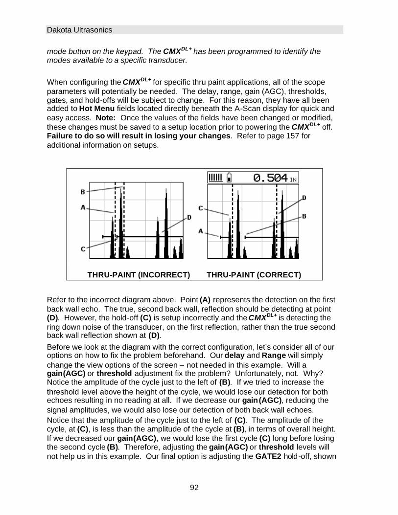
Dakota Ultrasonics
92
mode button on the keypad. The CMXDL+ has been programmed to identify the modes available to a specific transducer. When configuring the CMXDL+ for specific thru paint applications, all of the scope parameters will potentially be needed. The delay, range, gain (AGC), thresholds, gates, and hold-offs will be subject to change. For this reason, they have all been added to Hot Menu fields located directly beneath the A-Scan display for quick and easy access. Note: Once the values of the fields have been changed or modified, these changes must be saved to a setup location prior to powering the CMXDL+ off. Failure to do so will result in losing your changes. Refer to page 157 for additional information on setups.
THRU-PAINT (INCORRECT) THRU-PAINT (CORRECT)
Refer to the incorrect diagram above. Point (A) represents the detection on the first back wall echo. The true, second back wall, reflection should be detecting at point (D). However, the hold-off (C) is setup incorrectly and the CMXDL+ is detecting the ring down noise of the transducer, on the first reflection, rather than the true second back wall reflection shown at (D). Before we look at the diagram with the correct configuration, let’s consider all of our options on how to fix the problem beforehand. Our delay and Range will simply change the view options of the screen – not needed in this example. Will a gain(AGC) or threshold adjustment fix the problem? Unfortunately, not. Why? Notice the amplitude of the cycle just to the left of (B). If we tried to increase the threshold level above the height of the cycle, we would lose our detection for both echoes resulting in no reading at all. If we decrease our gain(AGC), reducing the signal amplitudes, we would also lose our detection of both back wall echoes. Notice that the amplitude of the cycle just to the left of (C). The amplitude of the cycle, at (C), is less than the amplitude of the cycle at (B), in terms of overall height. If we decreased our gain(AGC), we would lose the first cycle (C) long before losing the second cycle (B). Therefore, adjusting the gain(AGC) or threshold levels will not help us in this example. Our final option is adjusting the GATE2 hold-off, shown

CMXDL+ High Performance Material & Coating Thickness Gauge
93
at point (C) in the incorrect diagram, to point (B) in the correct diagram. If we adjust the GATE2 hold-off further to the right of the first reflection, the ring down noise from the first back wall echo no longer interferes with the true detection (D), shown in the correct diagram. The adjustment considerations in the example above will typically be used for all thru paint applications respectively. In some applications the hold -off may be sufficient, while a gain(AGC) or thresholds adjustment will solve the problem. A similar process of elimination should be considered for all thru paint applications.

94
CHAPTER NINE PULSE-ECHO COATING & COATING TECHNIQUES
9.1 Introduction to Pulse-Echo Coating Measurement (PECT) In the previous sections we’ve discussed the need for detecting pits and flaws (pulse-echo) in materials, along with the requirement to measure through and eliminate errors caused by coated materials (echo-echo). Until now, both modes were needed in order accomplish both tasks. Pulse-echo mode was used for flaw detection, and echo-echo mode was used to eliminate the coating thickness and provide a nominal material thickness only. With this in mind, it often became cumbersome toggling between both modes respectively. In a majority of applications involving coated materials, inspectors are often interested in monitoring both the thickness of the material, as well as the thickness of the coating. Therefore, the CMXDL+ has been designed to provide the user with the ability to measure the material and coating thicknesses simultaneously, while maintaining the ability to detect flaws and pits all in a single mode called Pulse-Echo Coating (PECT). This is accomplished by using a custom hybrid combination mode utilizing properties from the basic modes along with a group of special techniques and theoretical wave phenomena’s. The CMXDL+ is preset to a coating velocity of 0.0850 in/µsec (2159 m/sec) from the factory. This velocity is a very close approximation of the common coating velocities found in the field. However, the CMXDL+ also has a built-in one and two point calibration options to calibrate to coating samples with a known thicknesses. There are two coating modes built into the CMXDL+:
1) Pulse-Echo Coating (PECT) – used during inspections where both the material and coating thicknesses are required.
2) Coating Only (CT) – used during inspections where only the coating thickness is required.
9.2 Enabling Pulse-Echo Coating Mode (PECT) & Coating (CT) When the CMXDL+ is initially powered up, the gauge will automatically check to see if the transducer plugged into the gauge can be recognized. All Dakota Ultrasonics coating enabled transducers are equipped with the auto recognition feature. If the CMXDL+ doesn’t recognize that a special coating enabled transducer is plugged into the gauge, the coating feature will be disabled entirely. There are a number of coating enabled transducers available from Dakota. Please contact us with your application requirements for additional information on frequencies and diameters currently offered. The coating modes can be enabled in three different ways:
1) On Power up and probe recognition. 2) By pressing MULTI MODE keypad.

CMXDL+ High Performance Material & Coating Thickness Gauge
95
3) From the tabbed menus under TUNE, MEASURE MODE. The steps that follow will demonstrate all three methods in the order listed above:
Probe Automatically Recognized (PECT only)
1) Press the OK key once to use the identified probe, or ESC to display a list of
optional transducers. Note: if the CMXDL+ recognizes a specific
transducer, the user should always select OK to use the identified probe.
The only time an alternative probe should be selected from a list is if the
user switched probes following initial power up and recognition.
2) Assuming the CMXDL+ recognized the probe and the OK key was pressed,
the CMXDL+ will advance to a Zero Probe menu. If the transducer was
identified as a special transducer capable of measuring coating thickness, a
menu will be displayed allowing the user the ability to toggle the coating
thickness display on/off as follows:

Dakota Ultrasonics
96
3) Press the UP and DOWN arrow keys to toggle the coating option on/off.
Multi Mode Key Pressed (PECT & CT)
Applied to Metals Not Applied to Metals
1) Press the MULTI MODE key located on bottom left of the keypad to display
the MEASURE MODE options menu.
2) Press the UP and DOWN arrow keys to highlight the COATING ON (PECT)
or COATING ONLY (CT) menu option.

CMXDL+ High Performance Material & Coating Thickness Gauge
97
3) Press the ENTER key to enable the coating option, or ESC to cancel
changing the measure mode, and return to the main measurement screen.
Measure Mode (Tabbed Menus) – (PECT & CT)
Applied to Metals Not Applied to Metals
1) Press the MENU key once to activate the menu items tab. Press the MENU
key multiple times to tab right, and the ESC key multiple times to tab left,
until the TUNE menu is highlighted and displaying the submenu items.
2) Use the UP and DOWN arrow keys to scroll through the sub menu items
until MEASURE MODE is highlighted.
3) Press the LEFT and RIGHT arrow keys to scroll the modes.
4) When the correct MODE is being displayed, press the MEAS key to return
to the measurement screen and begin taking readings.

Dakota Ultrasonics
98
9.3 Zero Coating In order to account for very slight electronic differences in transducers of the same type, frequency, and diameter, the CMXDL+ has been equipped with a “zero coating” feature. This enables the CMXDL+ to obtain very accurate readings on coatings, eliminating potential errors incurred from slight differences in the manufacturing processes. The procedure is outlined below:
Performing a Coating Zero
1) Press the MULTI MODE key once to activate the measurement mode
options.
2) Use the UP and DOWN arrow keys to scroll through the sub menu items
until Coating Only (CT) mode is highlighted.
3) Press the ENTER key to select the measurement mode and return to the
measurement screen.
4) Apply a drop of couplant on the transducer and place the transducer in
steady contact with the probe zero disk (battery cover) and obtain a steady
reading.
Note: The coating measurement displayed will potentially be a value greater or
less than 0.

CMXDL+ High Performance Material & Coating Thickness Gauge
99
5) Press the MENU key once to activate the menu items tab. Press the MENU
key multiple times to tab right and the ESC key multiple times to tab left until
the PRB menu is highlighted and displaying the submenu items.
6) Use the UP and DOWN arrow keys to scroll through the sub menu items
until ZERO COATING is highlighted.
7) Press the ENTER key to display the confirmation screen.
8) Press the OK key to zero the coating and return to the PRB menu, or ESC
to cancel the coating zero process.
9) Press the MULTI MODE key once to activate the measurement mode
options.
10) Use the UP and DOWN arrow keys to scroll through the sub menu items
until Coating On (PECT) is highlighted.
11) Press the ENTER key to select the measurement mode and return to the
measurement screen, and begin taking readings. Proceed to the coating
calibration section.

Dakota Ultrasonics
100
9.4 Coating Calibration (PECT)
Known Velocity If the coating velocity is known, the user may wish to simply enter the velocity number into the CMXDL+, rather than have the CMXDL+ calculate the velocity value using a known thickness on a coating sample(s). The steps for entering the velocity are outlined below:
Using a Known Material Velocity
1) Press the MENU key once to activate the menu items tab. Press the MENU
key multiple times to tab right and the ESC key multiple times to tab left until
the CAL menu is highlighted and displaying the submenu items.
2) Use the UP and DOWN arrow keys to scroll through the sub menu items
until COATING VEL is highlighted.
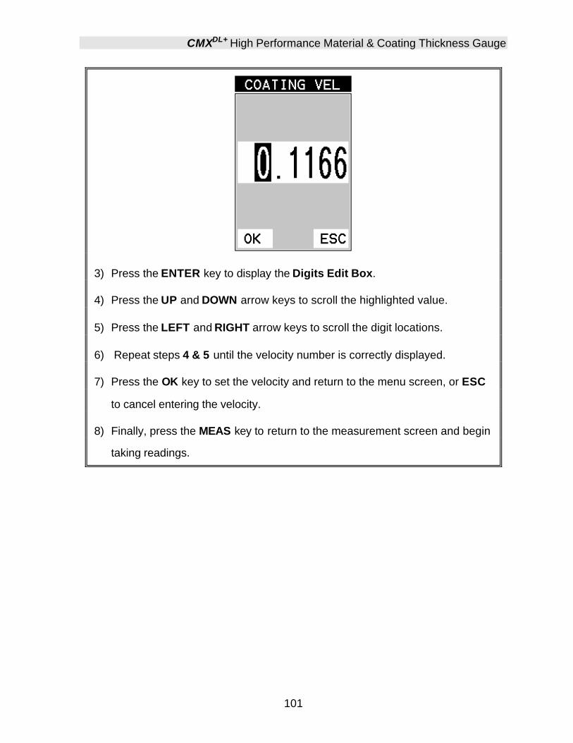
CMXDL+ High Performance Material & Coating Thickness Gauge
101
3) Press the ENTER key to display the Digits Edit Box.
4) Press the UP and DOWN arrow keys to scroll the highlighted value.
5) Press the LEFT and RIGHT arrow keys to scroll the digit locations.
6) Repeat steps 4 & 5 until the velocity number is correctly displayed.
7) Press the OK key to set the velocity and return to the menu screen, or ESC
to cancel entering the velocity.
8) Finally, press the MEAS key to return to the measurement screen and begin
taking readings.

Dakota Ultrasonics
102
Known Thickness Sometimes the sound velocity of a coating material is unknown. In this case a sample with a known thickness can be used to determine the sound velocity of the coating. As previously discussed, the CMXDL+ offers a one point calibration option for coating in PECT measurement mode. It is also import to reiterate that the coating sample must be coupled to a metallic material in order to perform the calibration. The calibration should also consider calibrating on high side of the intended measurement range, when using the one point option, minimize overall error. For example, if the measurement range of the coating will be from .040” - .080” (1.0mm 2.3mm), a coating closest to .080 (2.0mm) should be used. Note: It’s always handy to carry a set of mechanical calipers to use in conjunction with the CMXDL+ for calibration in the field:
One Point Calibration
Note: Be sure that the probe zero procedure has been performed prior to
performing this calibration procedure.
1) Physically measure an exact sample of the coating using a set of calipers or
a digital micrometer.
Note: The coating sample must be coupled to a metallic material in order to be
calibrated.
2) Apply a drop of couplant on a piece of metal and place the coating sample
on the metal over the couplant. Apply a drop of couplant on the transducer

CMXDL+ High Performance Material & Coating Thickness Gauge
103
and place the transducer in steady contact with the coating and sample or
actual test material. Be sure that the reading is stable and the repeatability
indicator, in the top left corner of the display, is fully lit and stable. Press the
MENU key once to activate the menu items tab. Press the MENU key
multiple times to tab right and the ESC key multiple times to tab left until the
CAL menu is highlighted and displaying the submenu items.
3) Use the UP and DOWN arrow keys to scroll through the sub menu items
until COATING 1PT is highlighted.
4) Press the ENTER key to display the Digits Edit Box.
5) Press the UP and DOWN arrow keys to scroll the highlighted value.
6) Press the LEFT and RIGHT arrow keys to scroll the digit locations.
7) Repeat steps 5 & 6 until the known thickness value is correctly displayed.
8) Press the OK key to calculate the velocity and return to the menu screen, or
ESC to cancel the coating one point calibration.
9) Finally, press the MEAS key to return to the measurement screen and begin
taking readings.

Dakota Ultrasonics
104
Note: CHECK YOUR CALIBRATION! Place the transducer back on the
calibration point. The coating thickness reading should now match the known
thickness. If the thickness is not correct, repeat the steps above.
9.5 Introduction to Coating Measurement (CT) In the previous sections we’ve discussed how to setup and use the coating feature for use in conjunction with material thickness for flaw and pit detection. The CMXDL+ also has the capability to be used for general coating measurements. This measurement mode is called Coating (CT) and can be enabled using the same methods as described in a previous section above. When the Coating Only (CT) mode is enabled, a two point calibration on the coating samples must be performed. This is to ensure linearity over the coating measurement range will be achieved. Important note: If coating measurements will be made with the coating applied to a metal surface, the calibration must be done in the same manner, with the samples coupled to a metal surface. However, if the coating will be measured as a stand alone material, the calibration must be performed the same way.
9.6 Two Point Coating Calibration (CT)
Known Thickness The following section will demonstrate the two point coating calibration procedure. This example demonstrates a coating thickness range of .040” - .120” (1 – 3 mm) as follows: Note: It’s always handy to carry a set of mechanical calipers to use in conjunction with the CMXDL+ for calibration in the field:

CMXDL+ High Performance Material & Coating Thickness Gauge
105
One Point Calibration
Note: Use the maximum coating sample for the one point calibration first.
1) Physically measure the thicker of the two samples of coating, as close as
possible to the maximum expected coating measurement range, using a set
of calipers or a digital micrometer.
Very Important: If coating measurements will be made with the coating
applied to a metal surface, the calibration must be done in the same manner,
with the samples coupled to a metal surface. However, if the coating will be
measured as a stand alone material, the calibration must be performed the
same way.
2) Apply a drop of couplant on the transducer and place the transducer in
steady contact with the thicker of the two coating and samples fist. Be sure
that the reading is stable and the repeatability indicator, in the top left corner
of the display, is fully lit and stable. Press the MENU key once to activate
the menu items tab. Press the MENU key multiple times to tab right and the
ESC key multiple times to tab left until the CAL menu is highlighted and
displaying the submenu items.

Dakota Ultrasonics
106
3) Use the UP and DOWN arrow keys to scroll through the sub menu items
until COATING 1PT is highlighted.
4) Press the ENTER key to display the Digits Edit Box.
5) Press the UP and DOWN arrow keys to scroll the highlighted value.
6) Press the LEFT and RIGHT arrow keys to scroll the digit locations.
7) Repeat steps 5 & 6 until the known thickness value is correctly displayed.
8) Press the OK key to calculate the velocity and return to the menu screen, or
ESC to cancel the coating one point calibration.
9) Finally, press the MEAS key to return to the measurement screen and begin
taking readings.
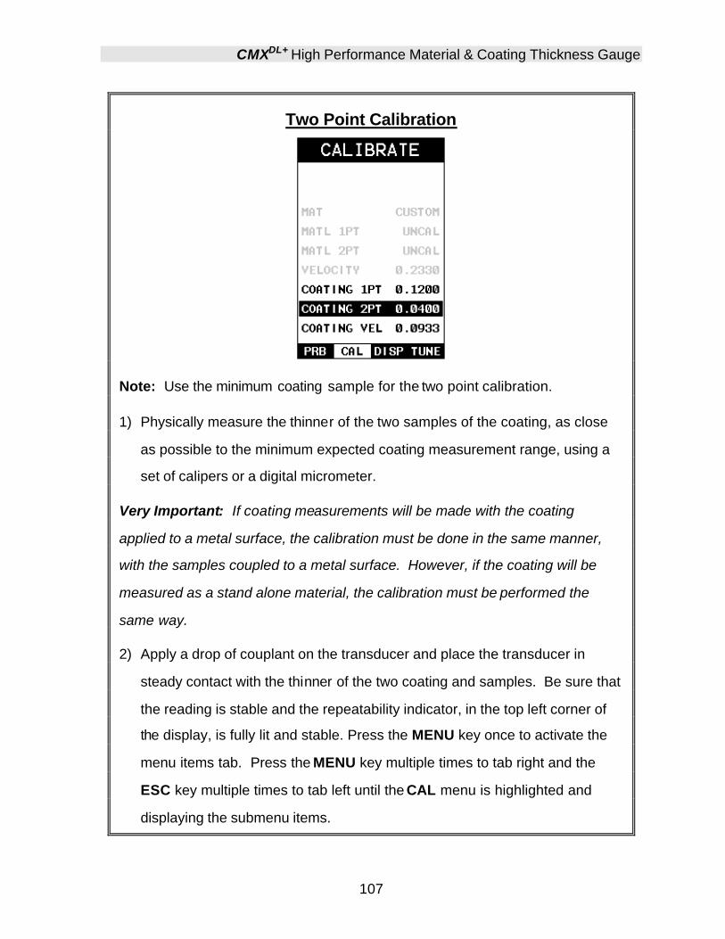
CMXDL+ High Performance Material & Coating Thickness Gauge
107
Two Point Calibration
Note: Use the minimum coating sample for the two point calibration.
1) Physically measure the thinner of the two samples of the coating, as close
as possible to the minimum expected coating measurement range, using a
set of calipers or a digital micrometer.
Very Important: If coating measurements will be made with the coating
applied to a metal surface, the calibration must be done in the same manner,
with the samples coupled to a metal surface. However, if the coating will be
measured as a stand alone material, the calibration must be performed the
same way.
2) Apply a drop of couplant on the transducer and place the transducer in
steady contact with the thinner of the two coating and samples. Be sure that
the reading is stable and the repeatability indicator, in the top left corner of
the display, is fully lit and stable. Press the MENU key once to activate the
menu items tab. Press the MENU key multiple times to tab right and the
ESC key multiple times to tab left until the CAL menu is highlighted and
displaying the submenu items.

Dakota Ultrasonics
108
3) Use the UP and DOWN arrow keys to scroll through the sub menu items
until COATING 2PT is highlighted.
4) Press the ENTER key to display the Digits Edit Box.
5) Press the UP and DOWN arrow keys to scroll the highlighted value.
6) Press the LEFT and RIGHT arrow keys to scroll the digit locations.
7) Repeat steps 5 & 6 until the known thickness value is correctly displayed.
8) Press the OK key to calculate the velocity and return to the menu screen, or
ESC to cancel the coating one point calibration.
9) Finally, press the MEAS key to return to the measurement screen and begin
taking readings.
Note: CHECK YOUR CALIBRATION! Place the transducer back on both
calibration points. The coating thickness readings should now match the known
thickness values of each sample. If the thickness is not correct, repeat the
steps above.
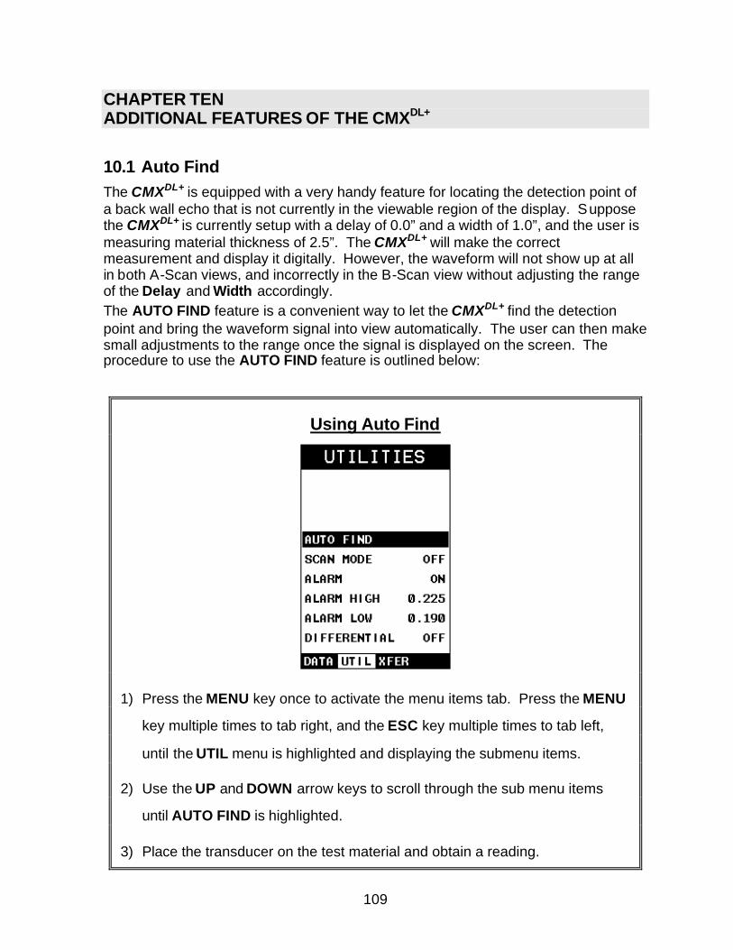
109
CHAPTER TEN ADDITIONAL FEATURES OF THE CMXDL+
10.1 Auto Find The CMXDL+ is equipped with a very handy feature for locating the detection point of a back wall echo that is not currently in the viewable region of the display. Suppose the CMXDL+ is currently setup with a delay of 0.0” and a width of 1.0”, and the user is measuring material thickness of 2.5”. The CMXDL+ will make the correct measurement and display it digitally. However, the waveform will not show up at all in both A-Scan views, and incorrectly in the B-Scan view without adjusting the range of the Delay and Width accordingly. The AUTO FIND feature is a convenient way to let the CMXDL+ find the detection point and bring the waveform signal into view automatically. The user can then make small adjustments to the range once the signal is displayed on the screen. The procedure to use the AUTO FIND feature is outlined below:
Using Auto Find
1) Press the MENU key once to activate the menu items tab. Press the MENU
key multiple times to tab right, and the ESC key multiple times to tab left,
until the UTIL menu is highlighted and displaying the submenu items.
2) Use the UP and DOWN arrow keys to scroll through the sub menu items
until AUTO FIND is highlighted.
3) Place the transducer on the test material and obtain a reading.

Dakota Ultrasonics
110
4) Press the ENTER key to automatically adjust the display settings and bring
the waveform into view.
5) Once the signal is displayed, press the MEAS key to return to measurement
mode.
10.2 High Speed Scan The High Speed Scan feature of the CMXDL+ increases the overall repetition rate to a maximum of 140Hz with a high speed screen refresh rate of 25 times a second. This feature enables a user to make scanned passes over an arbitrary length of the test material, while still maintaining a reasonable representation of thickness over the scanned area or region. This feature can be used in conjunction with High and Low alarm limits features to dynamically keep track of both values. The feature is typically used to provide a better representation of the area scanned, by taking more readings at a faster rate repetition rate. The procedure to use the SCAN MODE feature is outlined below:
Using the Scan Mode
1) Press the MENU key once to activate the menu items tab. Press the MENU
key multiple times to tab right and the ESC key multiple times to tab left until
the UTIL menu is highlighted and displaying the submenu items.

CMXDL+ High Performance Material & Coating Thickness Gauge
111
2) Use the UP and DOWN arrow keys to scroll through the sub menu items
until SCAN MODE is highlighted.
3) Use the LEFT and RIGHT arrow keys to toggle the SCAN MODE on/off.
4) Press the MEAS key to return to the measurement screen.
10.3 Alarm Mode The Alarm Mode feature of the CMXDL+ provides the user with a method of setting tolerances, or limits, for a particular application requirement. This feature may be used for a variety of applications to verify the material is within the manufacturer specifications. There are two limits, or alarm values, that can be setup in the CMXDL+ – ALARM LOW and ALARM HIGH limits. However, the user may choose to activate and utilize only one of the limit values, depending on their specific application requirements. The procedures to use the ALARM MODE feature are outlined below:
Toggle Alarm (on/off)
1) Press the MENU key once to activate the menu items tab. Press the MENU
key multiple times to tab right, and the ESC key multiple times to tab left,
until the UTIL menu is highlighted and displaying the submenu items.
2) Use the UP and DOWN arrow keys to scroll through the sub menu items
until ALARM is highlighted.

Dakota Ultrasonics
112
3) Use the LEFT and RIGHT arrow keys to toggle the ALARM on/off/audible.
4) Continue on to the next section “Setting the Alarm Low Limit”.
Setting the Alarm Low Limit
1) Assuming the ALARM is ON, use the UP and DOWN arrow keys to scroll
through the sub menu items until ALARM LOW is highlighted.
2) Press the LEFT and RIGHT arrow keys to scroll the value. When the
correct alarm value is being displayed, proceed to step 7 .
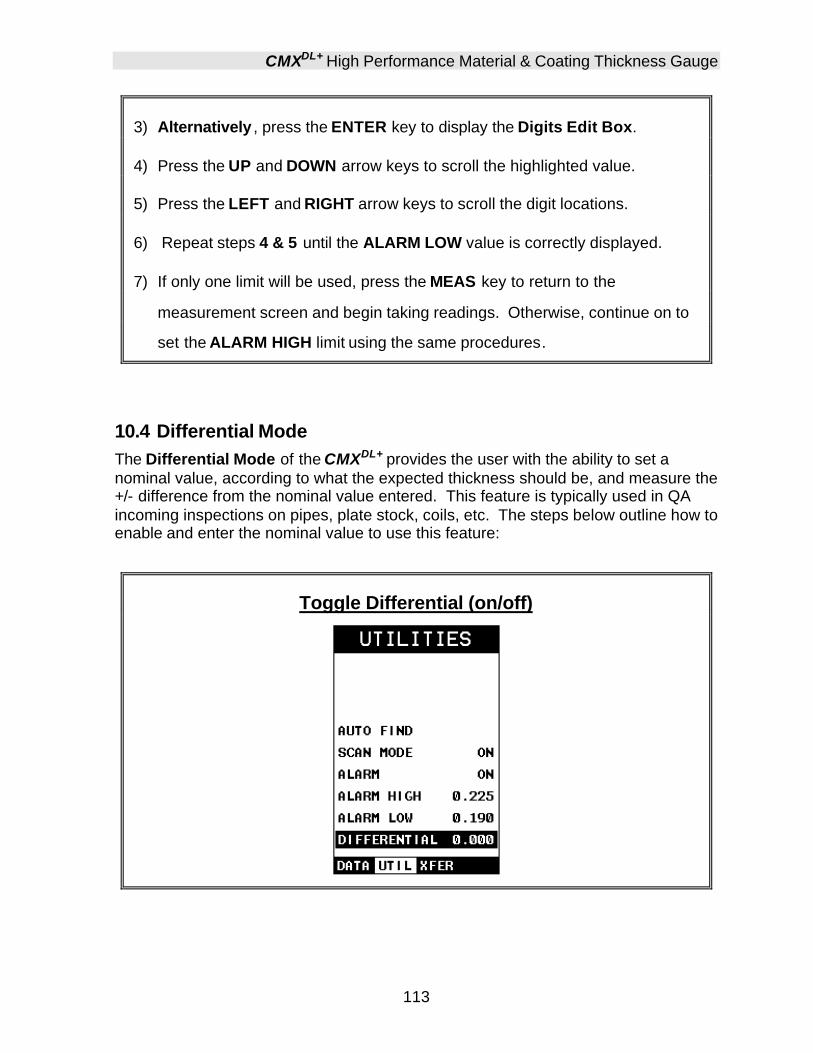
CMXDL+ High Performance Material & Coating Thickness Gauge
113
3) Alternatively , press the ENTER key to display the Digits Edit Box.
4) Press the UP and DOWN arrow keys to scroll the highlighted value.
5) Press the LEFT and RIGHT arrow keys to scroll the digit locations.
6) Repeat steps 4 & 5 until the ALARM LOW value is correctly displayed.
7) If only one limit will be used, press the MEAS key to return to the
measurement screen and begin taking readings. Otherwise, continue on to
set the ALARM HIGH limit using the same procedures.
10.4 Differential Mode The Differential Mode of the CMXDL+ provides the user with the ability to set a nominal value, according to what the expected thickness should be, and measure the +/- difference from the nominal value entered. This feature is typically used in QA incoming inspections on pipes, plate stock, coils, etc. The steps below outline how to enable and enter the nominal value to use this feature:
Toggle Differential (on/off)

Dakota Ultrasonics
114
1) Press the MENU key once to activate the menu items tab. Press the MENU
key multiple times to tab right, and the ESC key multiple times to tab left,
until the UTIL menu is highlighted and displaying the submenu items.
2) Use the UP and DOWN arrow keys to scroll through the sub menu items
until DIFFERENTIAL is highlighted.
3) Use the LEFT and RIGHT arrow keys to toggle the DIFFERENTIAL on. A
value will appear to the right of DIFFERENTIAL.
4) Continue on to the next section “Setting the Differential Value”.
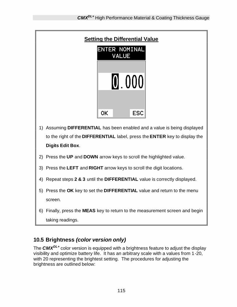
CMXDL+ High Performance Material & Coating Thickness Gauge
115
Setting the Differential Value
1) Assuming DIFFERENTIAL has been enabled and a value is being displayed
to the right of the DIFFERENTIAL label, press the ENTER key to display the
Digits Edit Box.
2) Press the UP and DOWN arrow keys to scroll the highlighted value.
3) Press the LEFT and RIGHT arrow keys to scroll the digit locations.
4) Repeat steps 2 & 3 until the DIFFERENTIAL value is correctly displayed.
5) Press the OK key to set the DIFFERENTIAL value and return to the menu
screen.
6) Finally, press the MEAS key to return to the measurement screen and begin
taking readings.
10.5 Brightness (color version only) The CMXDL+ color version is equipped with a brightness feature to adjust the display visibility and optimize battery life. It has an arbitrary scale with a values from 1 -20, with 20 representing the brightest setting. The procedures for adjusting the brightness are outlined below:

Dakota Ultrasonics
116
Adjusting Brightness
1) Press the MENU key once to activate the menu items tab. Press the MENU
key multiple times to tab right and the ESC key multiple times to tab left until
the DISP menu is highlighted and displaying the submenu items.
2) Use the UP and DOWN arrow keys to scroll through the sub menu items
until BRIGHTNESS is highlighted.
3) Press the LEFT and RIGHT arrow keys to scroll the value. When the
correct brightness value is being displayed, proceed to step 8.
4) Alternatively , press the ENTER key to display the Digits Edit Box.

CMXDL+ High Performance Material & Coating Thickness Gauge
117
5) Press the UP and DOWN arrow keys to scroll the highlighted value.
6) Press the LEFT and RIGHT arrow keys to scroll the digit locations.
7) Repeat steps 5 & 6 until the brightness number is correctly displayed.
8) Press the OK key to set the brightness and return to the menu screen, or
ESC to cancel entering the brightness.
9) Finally, press the MEAS key to return to the measurement screen and begin
taking readings.
10.6 VIEW (color version only)
The CMXDL+ color version has a variety of display color options to select from. These will change the look and feel of the according to the users preference. The procedures for changing the VIEW, are outlined below:
Selecting a Color Scheme
1) Press the MENU key once to activate the menu items tab. Press the MENU
key multiple times to tab right and the ESC key multiple times to tab left until
the DISP menu is highlighted and displaying the submenu items.

Dakota Ultrasonics
118
2) Use the UP and DOWN arrow keys to scroll through the sub menu items
until VIEW is highlighted.
3) Press the ENTER key to display a list of the color scheme options.
4) Press the UP and DOWN arrow keys to scroll through the material list until
the appropriate material is highlighted.
5) Press the ENTER key, followed by pressing the OK key, to overwrite the
current color scheme with the selected scheme.
6) Finally, press the MEAS key to return to the measurement screen and begin
taking readings.
10.7 DIM (color version only) The CMXDL+ color version has a built-in DIM feature to manage power more effectively. This feature has adjustable time durations, until the power of the display is dimmed and current draw reduced. The timer is constantly reset while the user is making measurements, and is only activated when the gauge is idle for the duration of time the DIM value is set for. This feature does not override the preset 5 min idle power off feature in any way. However, if the gauge is turned on, set for a DIM of 120sec, and then left idle for 5 minutes, the CMXDL+ will dim in 2 minutes, then power off in 5 minutes. The procedures for adjusting the DIM time are outlined below:

CMXDL+ High Performance Material & Coating Thickness Gauge
119
Setting a DIM time
1) Press the MENU key once to activate the menu items tab. Press the MENU
key multiple times to tab right and the ESC key multiple times to tab left until
the DISP menu is highlighted and displaying the submenu items.
2) Use the UP and DOWN arrow keys to scroll through the sub menu items
until DIM is highlighted.
3) Press the LEFT and RIGHT arrow keys to scroll the DIM time.
4) Finally, press the MEAS key to return to the measurement screen and begin
taking readings.
10.8 Damping (color version only) The color version of the CMXDL+ has a built-in damping feature to control the impedance input of the receiver. This enables the user the ability to match and optimize the transducer for better signal quality at various frequencies. The available settings are 50, 75, 100, 300, 600 and 1500 ohms. The procedures below outline the steps for selecting an impedance setting, as follows:
Setting the Damping Value

Dakota Ultrasonics
120
1) Press the MENU key once to activate the menu items tab. Press the MENU
key multiple times to tab right, and the ESC key multiple times to tab left,
until the TUNE menu is highlighted and displaying the submenu items.
2) Use the UP and DOWN arrow keys to scroll through the sub menu items
until DAMPING is highlighted.
3) Use the LEFT and RIGHT arrow keys to scroll through the DAMPING values
until the correct value is displayed to the right of the DAMPING menu item.
4) Finally, press the MEAS key to return to the measurement screen and begin
taking readings.
10.9 Introduction to Flaw Mode The Flaw Mode feature was added to the CMXDL+ to provide inspectors with a basic prove-up flaw detection mode using an angle beam transducer. This mode enables inspectors to locate porosity, defects, inclusions, and cracks in a variety of test materials. Angle beam transducers, are transducers attached to a delay line wedge at specific angles. Some of the more common angles are 45°, 60°, and 70°. The sound wave is introduced into the test material at a specific angle, and converted from a longitudinal wave into a shear wave. The introduction at specific angles enables inspectors to steer the sound wave in a specific direction according to the position and location of specific types of defects.

CMXDL+ High Performance Material & Coating Thickness Gauge
121
Note: The CMXDL+ AMOLED high speed color version has a 120Hz screen redraw rate and exceeds the speed found in conventional digital flaw detectors.
Angle Beam Transducer Weld Inspection
Flaw Mode View:
Flaw Mode View
Refer to the diagram above. The grey grid line, point (A), corresponds to 100% FSH (Full Screen Height). The other grid lines correspond to 25% amplitude increments, in order to calibrate the CMXDL+ in this mode. The digital thickness value has been replaced by dashed lines at point (B). The digital thickness value is not applicable while operating in this mode. Notice at point (D), the vertical grid lines have simply been given quadrant numbers. Again, this is because the grid lines do not correspond to a thickness value based on the delay and width of the screen. Finally,
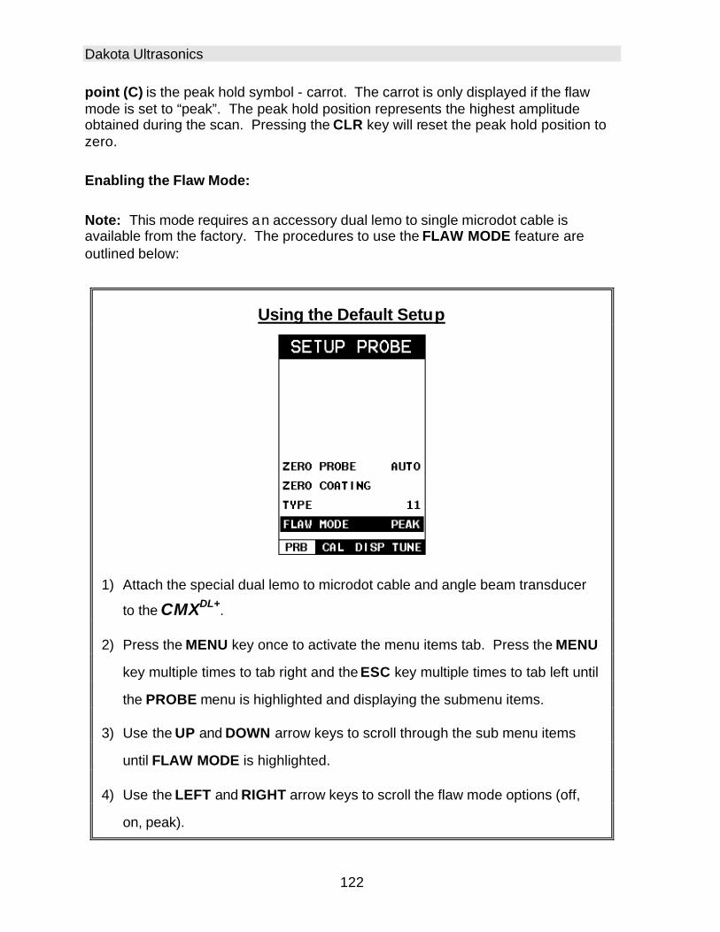
Dakota Ultrasonics
122
point (C) is the peak hold symbol - carrot. The carrot is only displayed if the flaw mode is set to “peak”. The peak hold position represents the highest amplitude obtained during the scan. Pressing the CLR key will reset the peak hold position to zero. Enabling the Flaw Mode: Note: This mode requires an accessory dual lemo to single microdot cable is available from the factory. The procedures to use the FLAW MODE feature are outlined below:
Using the Default Setup
1) Attach the special dual lemo to microdot cable and angle beam transducer
to the CMXDL+.
2) Press the MENU key once to activate the menu items tab. Press the MENU
key multiple times to tab right and the ESC key multiple times to tab left until
the PROBE menu is highlighted and displaying the submenu items.
3) Use the UP and DOWN arrow keys to scroll through the sub menu items
until FLAW MODE is highlighted.
4) Use the LEFT and RIGHT arrow keys to scroll the flaw mode options (off,
on, peak).
CMXDL+ High Performance Material & Coating Thickness Gauge
123
Off: Disables the Flaw Mode option.
On: Enables the Flaw Mode option and view.
Peak: Enables the Flaw Mode and Peak Hold options and view. When this
option is enabled, a carrot will appear on the right side of the display. The
position of the carrot corresponds to the highest waveform amplitude value
detected. In order to clear the peak hold carrot location and start another scan,
the CLR key must be pressed. When pressed, the carrot will be displayed at
the baseline, or at zero amplitude.
5) Once the desired flaw mode is displayed, press the MEAS key to return to
measurement mode.
Note: All the features previously discussed in this manual can be used to
adjust and fine tune the CMXDL+ while in Flaw Mode.
Note: When flaw mode is activated, a transducer delay will still be configured
from the previously loaded transducer. This will only affect the starting
point from the initial pulse from being at zero. The zero delay can be set to
zero by loading the default setup located in the setup menu. Alternatively,
the user can load a factory flaw mode setup, from the setups folder, and
begin making any adjustments necessary. Refer to page 157 for further
info.
10.10 Graphics Options (look & feel) We’ve added a couple of graphic interface features to the CMXDL+ , accommodate customer requests we’ve received in the past. These features only serve as cosmetic items, and do not change the functionality of the CMXDL+ in any way. RECT Wave:
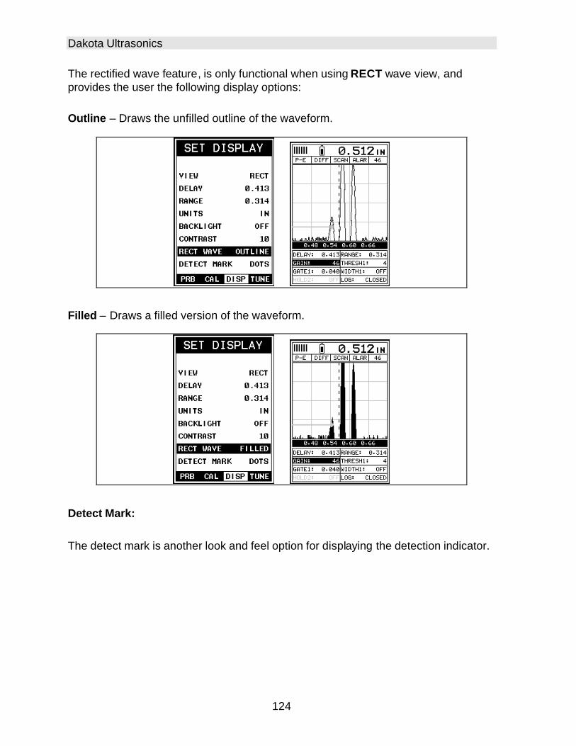
Dakota Ultrasonics
124
The rectified wave feature, is only functional when using RECT wave view, and provides the user the following display options: Outline – Draws the unfilled outline of the waveform.
Filled – Draws a filled version of the waveform.
Detect Mark: The detect mark is another look and feel option for displaying the detection indicator.

CMXDL+ High Performance Material & Coating Thickness Gauge
125
10.11 Polarity The CMXDL+ is equipped with an option to select the polarity, or phase +/-, for the purpose of detection. The phase can be a very valuable feature to have when the signal returning from the test material is marginal, a low frequency transducer is being used, and the user has a very weak positive or negative cycle, while trying to measure very thick materials. There is a possibility that signal will become so weak that it falls below the threshold, and peak jumps to the next cycle altogether. This peak jump represents a shift of the detection further out in time, resulting incorrect measurements. The material being measured will appear thicker than it actually is. Refer to the diagram below:

Dakota Ultrasonics
126
Notice the +/- positions in the diagram. The positive phase is everything above the horizontal center line, and the negative everything below the center line. The CMXDL+ uses a zero crossing (flank) method for detection. Therefore, the detect line (A) is represented by the broken vertical dotted line, and is currently detecting on the negative portion of the waveform (B) at the zero crossing (C). The signal amplitude (B) is shown as the negative vertical height at (B) in the diagram. Refer to the height of the second negative peak at (G). It’s clear that the amplitude of (G) is much greater than that of (B). Therefore, if the user was measuring thick attenuative material, and the amplitude of (B) decreased substantially, the CMXDL+ would lose the first cycle (B) and peak jump to the second cycle (F). The detect (A), would move to (F), resulting in incorrect measurements. If the user were to select the positive phase in the diagram above, the detect would measure at (H). (A) would move to (H). Notice the height of (D) with respect to the height of (E) in the diagram. If the user was measuring thick attenuative material using this phase, the signal (E) will certainly be lost long before (D). Therefore, the positive phase is a much better choice in the diagram above.
Toggle Polarity (+/-)
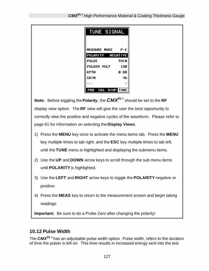
CMXDL+ High Performance Material & Coating Thickness Gauge
127
Note: Before toggling the Polarity, the CMXDL+ should be set to the RF
display view option. The RF view will give the user the best opportunity to
correctly view the positive and negative cycles of the waveform. Please refer to
page 61 for information on selecting the Display Views.
1) Press the MENU key once to activate the menu items tab. Press the MENU
key multiple times to tab right, and the ESC key multiple times to tab left,
until the TUNE menu is highlighted and displaying the submenu items.
2) Use the UP and DOWN arrow keys to scroll through the sub menu items
until POLARITY is highlighted.
3) Use the LEFT and RIGHT arrow keys to toggle the POLARITY negative or
positive.
4) Press the MEAS key to return to the measurement screen and begin taking
readings.
Important: Be sure to do a Probe Zero after changing the polarity!
10.12 Pulse Width The CMXDL+ has an adjustable pulse width option. Pulse width, refers to the duration of time the pulser is left on. This time results in increased energy sent into the test

Dakota Ultrasonics
128
material. There are three width options (SPIKE, THIN, and WIDE). The SPIKE setting may be desirable for high resolution and general applications to decrease the overall noise. This can be considered the normal or standard setting. When additional energy is needed, more penetration, the THIN and WIDE options may be necessary. The procedure to change the pulse width is outlined below:
Selecting the Pulse Width
1) Press the MENU key once to activate the menu items tab. Press the MENU
key multiple times to tab right and the ESC key multiple times to tab left until
the TUNE menu is highlighted and displaying the submenu items.
2) Use the UP and DOWN arrow keys to scroll through the sub menu items
until PULSE is highlighted.
3) Use the LEFT and RIGHT arrow keys to scroll the Pulse options.
4) Once the Pulse is displayed, press the MEAS key to return to the
measurement screen.
10.13 Pulser Voltage The CMXDL+ has a 200 volt square wave pulser that can be adjusted for specific applications and transducers. The Pulser Volt feature offers a 50 volt cut/boost
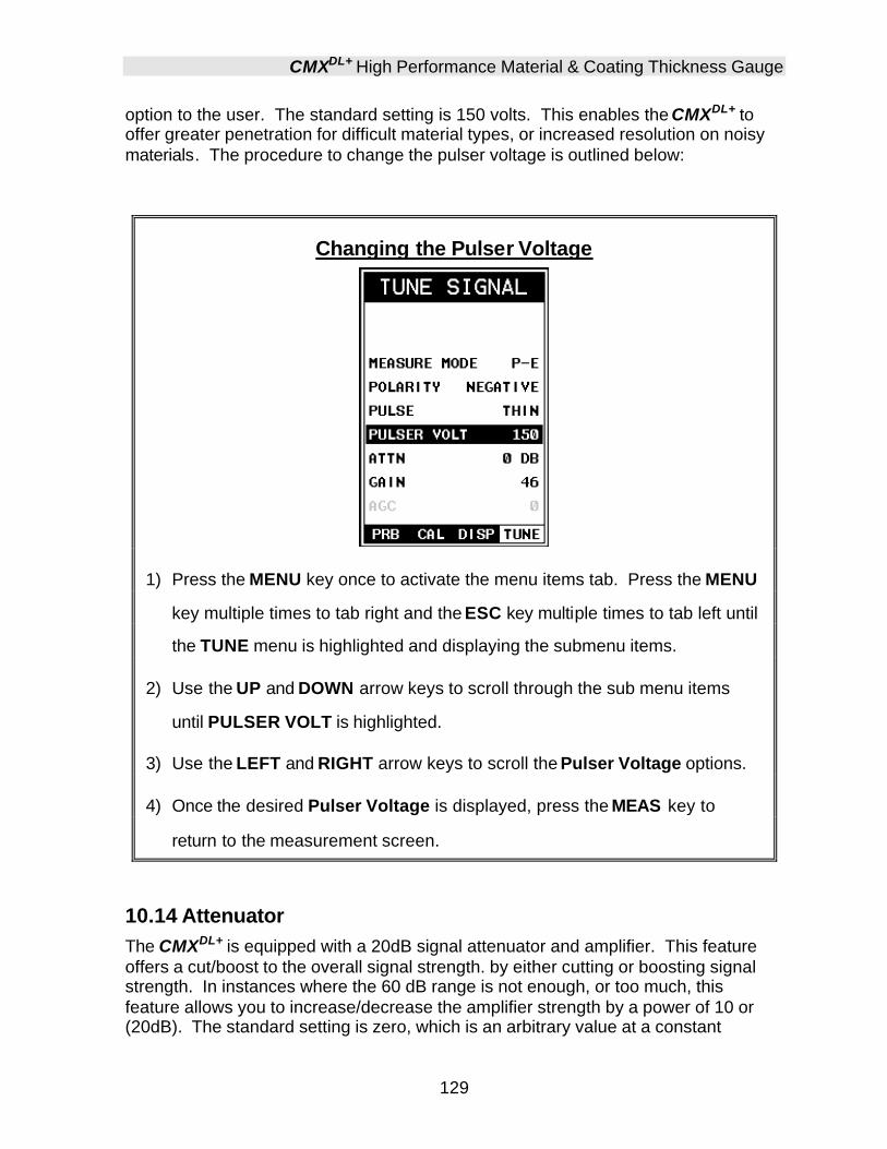
CMXDL+ High Performance Material & Coating Thickness Gauge
129
option to the user. The standard setting is 150 volts. This enables the CMXDL+ to offer greater penetration for difficult material types, or increased resolution on noisy materials. The procedure to change the pulser voltage is outlined below:
Changing the Pulser Voltage
1) Press the MENU key once to activate the menu items tab. Press the MENU
key multiple times to tab right and the ESC key multiple times to tab left until
the TUNE menu is highlighted and displaying the submenu items.
2) Use the UP and DOWN arrow keys to scroll through the sub menu items
until PULSER VOLT is highlighted.
3) Use the LEFT and RIGHT arrow keys to scroll the Pulser Voltage options.
4) Once the desired Pulser Voltage is displayed, press the MEAS key to
return to the measurement screen.
10.14 Attenuator The CMXDL+ is equipped with a 20dB signal attenuator and amplifier. This feature offers a cut/boost to the overall signal strength. by either cutting or boosting signal strength. In instances where the 60 dB range is not enough, or too much, this feature allows you to increase/decrease the amplifier strength by a power of 10 or (20dB). The standard setting is zero, which is an arbitrary value at a constant

Dakota Ultrasonics
130
attenuation. The attenuation value is added to the gain value. Therefore, if the attenuator is increased to 20dB, this value is added to the value of the gain setting. The procedure to change the attenuator is outlined below:
Changing the Attenuator Setting
1) Press the MENU key once to activate the menu items tab. Press the MENU
key multiple times to tab right and the ESC key multiple times to tab left until
the TUNE menu is highlighted and displaying the submenu items.
2) Use the UP and DOWN arrow keys to scroll through the sub menu items
until ATTN is highlighted.
3) Use the LEFT and RIGHT arrow keys to scroll the Attenuator options.
4) Once the desired Attenuation is displayed, press the MEAS key to return to
the measurement screen.
131
CHAPTER ELEVEN DATA STORAGE – SETUP, EDIT, & VIEW FILES
11.1 Introduction to Grid and Sequential file formats The CMXDL+ is equipped with two data file format options, GRID LOG and SEQ LOG. The GRID file format is very similar to a spreadsheet format found in popular software programs like Excel. A GRID is simply a table of readings. A location in a grid is specified by giving a row and column coordinate. The rows are numbered from 1 to 999 and the columns are labeled from A to ZZ (999 Rows & 52 Columns). The sequential file format can be viewed as a file as a single column of up to 512 possible rows (readings), and a column of corresponding identifiers associated with each individual reading. The identifier can be a combination of up to 10 numeric, alpha, or special characters listed above, while the file name can consist of a combination of up to 20 of the same character set. Note: The identifier cannot start or end with a special character. Once a start and end ID are entered into the CMXDL+ and the log created, the CMXDL+ will automatically generate all the identifiers within that range. The following character set listed below are all the allowable characters that will be used for both file formats: GRID & SEQ LOG. Any combination of these characters can be used for creating a Name and Note regardless of the selected format. The allowable characters are as follows: Numeric characters: 0 – 9 Alpha Characters: A – Z Special Characters: ! ‘ _ # space / . – ( ) Multiple grids can be created and stored until the CMXDL+’s memory is full. If the user attempts to store a new file in the CMXDL+ and the size of the file exceeds the capacity of memory, the CMXDL+ will respond with an error message indicating that the memory is unable to store the new file. The CMXDL+ can store a total of 16,000+ readings with a corresponding screenshot of the DIGITS, RF, RECT, or B-SCAN views with every reading , as well as all the CMXDL+ settings for every individual reading. If the graphics option is disabled, not saving screenshots, the CMXDL+ can store a total of 210,000+ readings. The screenshot stored with the reading will depend on what view the CMXDL+ was in at the time it was saved. For example, if the view was in RECT, then a RECT will be saved with the reading. In the sections that follow, the procedures for creating, using, and editing GRID’s and SEQ LOG’s have been combined together for the purpose of similarity in overall

Dakota Ultrasonics
132
functionality and structure. The illustrations below are snapshots of typical GRID and SEQ LOG file formats:
Grid File Formats
Sequential Log Formats
Important Note: For the duration of this chapter, all references to GRIDS and SEQ LOGS should be considered synonymous with references to FILES.
11.2 Creating a new Grid or Sequential Log (File) Important Note: This entire section is a step by step guide to successfully create a grid or sequential log. The instructions must be used in the sequential order specified, as follows:
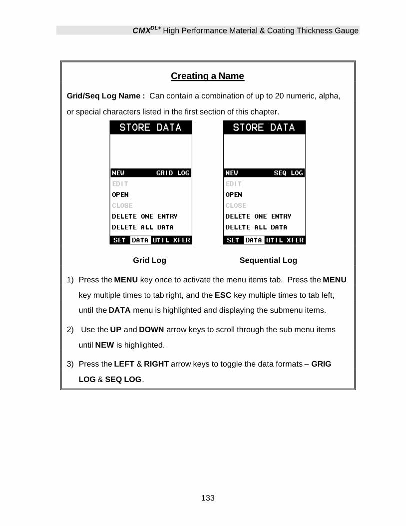
CMXDL+ High Performance Material & Coating Thickness Gauge
133
Creating a Name
Grid/Seq Log Name : Can contain a combination of up to 20 numeric, alpha,
or special characters listed in the first section of this chapter.
Grid Log Sequential Log
1) Press the MENU key once to activate the menu items tab. Press the MENU
key multiple times to tab right, and the ESC key multiple times to tab left,
until the DATA menu is highlighted and displaying the submenu items.
2) Use the UP and DOWN arrow keys to scroll through the sub menu items
until NEW is highlighted.
3) Press the LEFT & RIGHT arrow keys to toggle the data formats – GRIG
LOG & SEQ LOG.

Dakota Ultrasonics
134
Grid Log Sequential Log
4) Press the ENTER key to display the new Grid or Seq Edit Box.
5) Use the UP and DOWN arrow keys to scroll through the new Grid or Seq
List Items until NAME is highlighted.
6) Press the ENTER key to activate the Alpha Edit Box.
7) Use the UP, DOWN, LEFT, & RIGHT arrow keys to highlight the appropriate
alpha characters.
8) Press the ENTER key to select a character and advance to the next field of
the Grid or Seq Name.

CMXDL+ High Performance Material & Coating Thickness Gauge
135
9) Use the CLR key to backspace if necessary.
10) Repeat steps 6 - 9 until the Grid or Seq Name (File Name) is completed.
11) Press the OK key to save the Grid or Seq Name and return to the Grid or
Seq List Items menu, or ESC to cancel entering the Grid or Seq Name
(File Name).
Creating a Note
Grid/Seq Log Note: Can contain a combination of up to 20 numeric, alpha, or
special characters listed in the first section of this chapter.
Grid Log Sequential Log
1) Assuming the Grid or Seq List Items are displayed, use the UP and DOWN
arrow keys to scroll through the new Grid or Seq List Items until NOTE is
highlighted.
2) Press the ENTER key to activate the Alpha Edit Box.
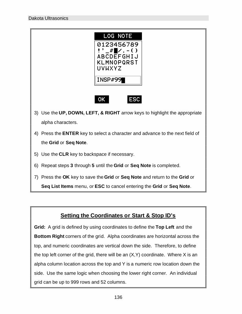
Dakota Ultrasonics
136
3) Use the UP, DOWN, LEFT, & RIGHT arrow keys to highlight the appropriate
alpha characters.
4) Press the ENTER key to select a character and advance to the next field of
the Grid or Seq Note.
5) Use the CLR key to backspace if necessary.
6) Repeat steps 3 through 5 until the Grid or Seq Note is completed.
7) Press the OK key to save the Grid or Seq Note and return to the Grid or
Seq List Items menu, or ESC to cancel entering the Grid or Seq Note.
Setting the Coordinates or Start & Stop ID’s
Grid: A grid is defined by using coordinates to define the Top Left and the
Bottom Right corners of the grid. Alpha coordinates are horizontal across the
top, and numeric coordinates are vertical down the side. Therefore, to define
the top left corner of the grid, there will be an (X,Y) coordinate. Where X is an
alpha column location across the top and Y is a numeric row location down the
side. Use the same logic when choosing the lower right corner. An individual
grid can be up to 999 rows and 52 columns.

CMXDL+ High Performance Material & Coating Thickness Gauge
137
Sequential: The sequential file format can be viewed as a file as a single
column of up to 512 possible rows (readings), and a column of corresponding
identifiers associated with each individual reading. The identifier can be a
combination of up to 10 numeric, alpha, or special characters listed above,
while the file name can consist of a combination of up to 20 of the same
character set. Note: The identifier cannot start or end with a special character.
Once a start and end ID are entered into the CMXDL+ and the log created, the
CMXDL+ will automatically generate all the identifiers within that range.
Setting the Top Left(Grid) or Start ID(Seq)
Grid Log Sequential Log
1) Use the UP and DOWN arrow keys to scroll through the new Grid or Seq
List Items until TOP LEFT or START ID is highlighted.
2) Press the ENTER key to activate the Coordinate or Start ID Edit Box.

Dakota Ultrasonics
138
Grid Log Sequential Log
3) GRID LOG: Use the LEFT, & RIGHT arrow keys to scroll the Columns,
and the UP, DOWN arrow keys to scroll the Rows.
SEQ LOG: Use the UP, DOWN, LEFT, & RIGHT arrow keys to highlight the
appropriate alpha characters. Press the ENTER key to select a character
and advance to the next character field, in conjunction with using the CLR
key to backspace if necessary.
4) Press the OK key to select the coordinate or start ID and return to the Grid
or Seq List Items screen, or ESC to cancel the selection and return to the
Grid or Seq List Items menu.
Setting the Bottom Right(Grid) or End ID(Seq)

CMXDL+ High Performance Material & Coating Thickness Gauge
139
Grid Log Sequential Log
1) Use the UP and DOWN arrow keys to scroll through the new Grid or Seq
List Items until LOWER RIGHT or END ID is highlighted.
2) Press the ENTER key to activate the Coordinate or End ID Edit Box.
Grid Log Sequential Log
3) GRID LOG: Use the LEFT, & RIGHT arrow keys to scroll the Columns,
and the UP, DOWN arrow keys to scroll the Rows.
SEQ LOG: Use the UP, DOWN, LEFT, & RIGHT arrow keys to highlight the
appropriate alpha characters. Press the ENTER key to select a character

Dakota Ultrasonics
140
and advance to the next character field, in conjunction with using the CLR
key to backspace if necessary.
4) Press the OK key to select the coordinate or end ID and return to the Grid
or Seq List Items screen, or ESC to cancel the selection and return to the
Grid or Seq List Items menu.
Note: If there is not enough memory available to create the grid or sequential
log, an error message box “NOT ENOUGH MEMORY“ will be displayed. Press
the OK or ESC key to return to the Grid or Seq List Items menu. It may be
necessary to free some memory in the CMXDL+ at this time. Refer to page 147
for more information on Deleting a File.
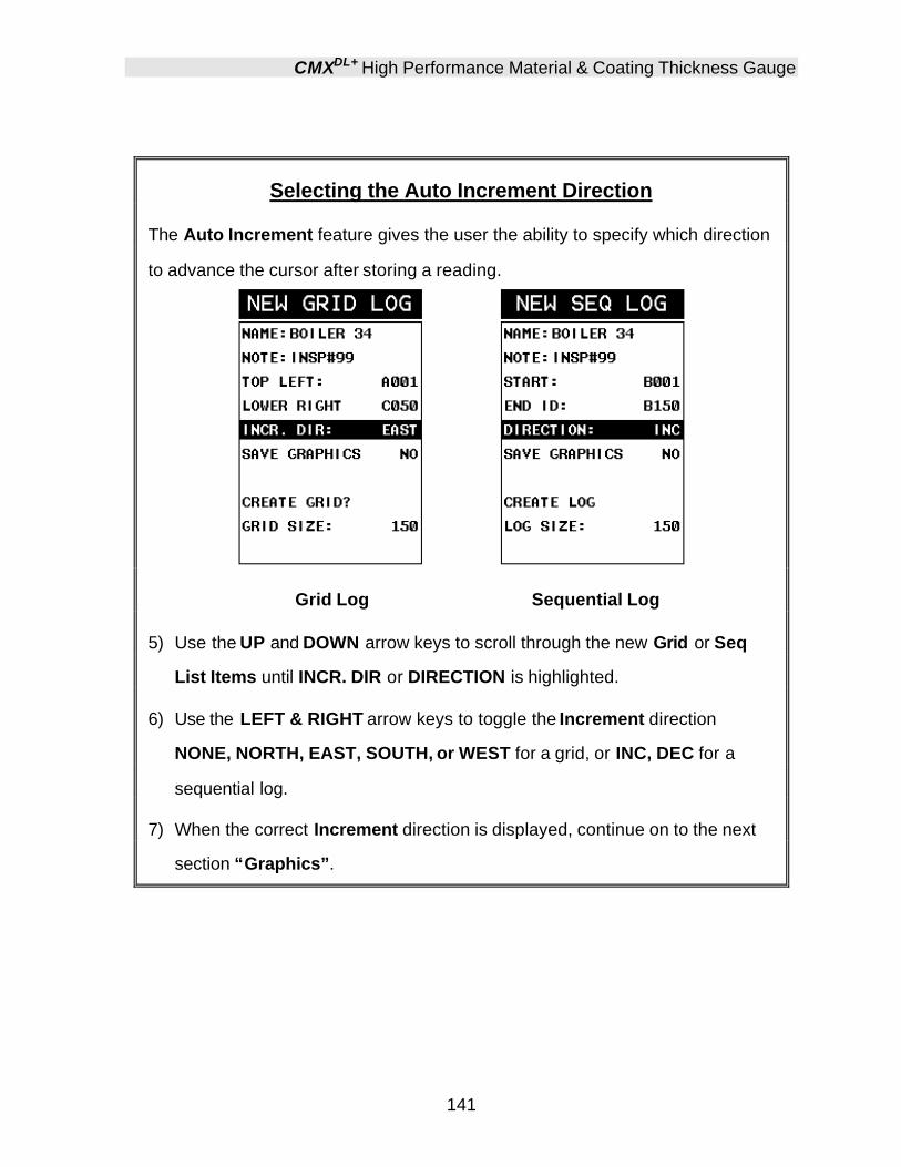
CMXDL+ High Performance Material & Coating Thickness Gauge
141
Selecting the Auto Increment Direction
The Auto Increment feature gives the user the ability to specify which direction
to advance the cursor after storing a reading.
Grid Log Sequential Log
5) Use the UP and DOWN arrow keys to scroll through the new Grid or Seq
List Items until INCR. DIR or DIRECTION is highlighted.
6) Use the LEFT & RIGHT arrow keys to toggle the Increment direction
NONE, NORTH, EAST, SOUTH, or WEST for a grid, or INC, DEC for a
sequential log.
7) When the correct Increment direction is displayed, continue on to the next
section “Graphics”.

Dakota Ultrasonics
142
Saving Graphics
The CMXDL+ provides the user with the ability to save a snapshot of the display
screen and all the current settings of the CMXDL+ with every reading, or just
save the reading only. Saving the graphics might be advantageous to the user
when the A/B-Scan views will be used to graphically save a picture of the
scanned areas for reporting purposes. It might also come in handy when user
requires backup of all the current CMXDL+ parameters for each reading.
However, if neither of these requirements are necessary, this option should be
disabled in order make more efficient use to the CMXDL+ storage capacity.
Grid Log Sequential Log
1) Use the UP and DOWN arrow keys to scroll through the new Grid or Seq
List Items until SAVE GRAPHICS is highlighted.
2) Use the LEFT & RIGHT arrow keys to toggle the Increment direction to
YES or NO.
3) Continue on to the next section “Saving a Grid or Seq File”.

CMXDL+ High Performance Material & Coating Thickness Gauge
143
Saving a Grid
Once all the parameters are set, the user has the option of saving or canceling
the new grid.
Grid Log Sequential Log
4) Use the UP and DOWN arrow keys to scroll through the new Grid or Seq
List Items until CREATE GRID or LOG? is highlighted.
5) Press the ENTER key to accept the grid or seq log parameters and activate
the confirmation screen.

Dakota Ultrasonics
144
Grid Log Sequential Log
6) Press the OK key to save the New Grid or Seq Log, or the ESC key to
cancel the New Grid or Seq Log setup and return to the DATA menu.
7) Press the MEAS key to return to the measurement screen and begin storing
readings.
11.3 Storing a reading Now that a grid or sequential log has been created, it’s time to make some measurements and store the readings. The following procedures outline this process:
Storing a Reading
Note: Once the gird or sequential log has been created it will automatically be
displayed following the create confirmation screen. It is located at the bottom of
the measurement screen, and can be left open for the duration of the inspection
process. This section assumes the grid or sequential log was just created.
Refer to the section on “opening a grid or seq log” if the file was created at
another time.
Key Feature: When the CMXDL+ is displaying a “grid log”, pressing the OK
key will initiate an advance to row number option. Use the Left, Right, UP, and
DOWN arrow keys to enter the row number. Once the row number is correctly
displayed, press the OK key to advance directly to that row number in the grid
log.
Key Feature: When the CMXDL+ is displaying a “grid log”, pressing the ESC
key multiple times, will toggle through the display options: Digits, RF, RECT,
and B-SCAN views.
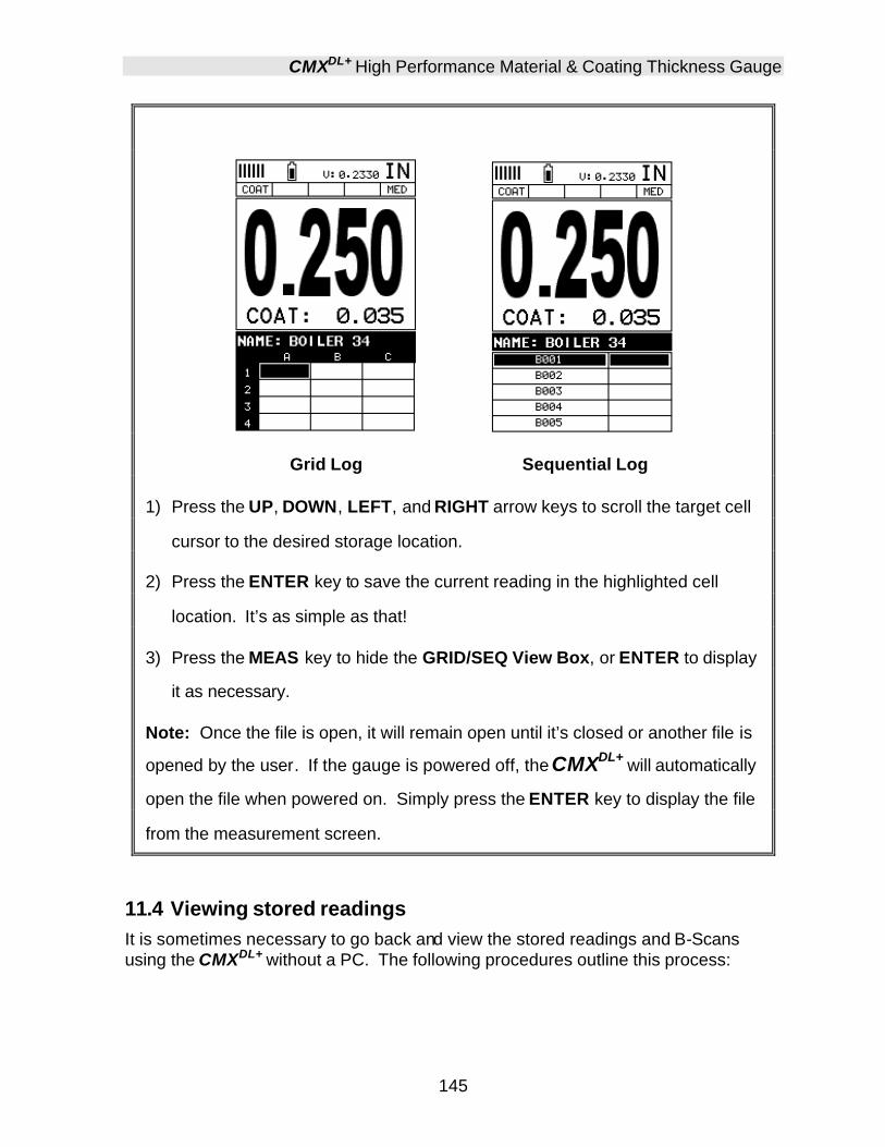
CMXDL+ High Performance Material & Coating Thickness Gauge
145
Grid Log Sequential Log
1) Press the UP, DOWN, LEFT, and RIGHT arrow keys to scroll the target cell
cursor to the desired storage location.
2) Press the ENTER key to save the current reading in the highlighted cell
location. It’s as simple as that!
3) Press the MEAS key to hide the GRID/SEQ View Box, or ENTER to display
it as necessary.
Note: Once the file is open, it will remain open until it’s closed or another file is
opened by the user. If the gauge is powered off, the CMXDL+ will automatically
open the file when powered on. Simply press the ENTER key to display the file
from the measurement screen.
11.4 Viewing stored readings It is sometimes necessary to go back and view the stored readings and B-Scans using the CMXDL+ without a PC. The following procedures outline this process:

Dakota Ultrasonics
146
Viewing Stored Readings & A/B Scans
Grid Log Sequential Log
1) Press the MEAS key once to activate measure menu items. Press the
MEAS key multiple times to move right and the ESC key multiple times to
move left until the LOG cell is highlighted.
2) Press the ENTER key to display the Grid Log Box.
3) Press the UP, DOWN, LEFT, and RIGHT arrow keys to scroll the stored
readings and corresponding display view. Notice as the cursor is moved to
a different cell, the display will be updated with the display view saved with

CMXDL+ High Performance Material & Coating Thickness Gauge
147
the reading. Readings stored in memory are indicated by displaying a MEM
in the top left corner of the measurement screen.
4) The user may opt to clear a specific reading and save a new one at any
time. Press the CLR key in the appropriate cell location to clear the reading,
take a new measurement, and press the ENTER key to save the new
reading.
5) Abort the Grid/Seq Log View Box by pressing the MEAS key at any time.
11.5 Deleting Grids (Files)
Deleting One or All Files from Memory
Deleting One File
1) Press the MENU key once to activate the menu items tab. Press the MENU
key multiple times to tab right and the ESC key multiple times to tab left until
the DATA menu is highlighted and displaying the submenu items.

Dakota Ultrasonics
148
2) Use the UP and DOWN arrow keys to scroll through the sub menu items
until DELETE ONE FILE is highlighted.
3) Press the ENTER key to display the File List Box.
4) Use the UP and DOWN arrow keys to scroll through the stored Files until
the target File to delete is highlighted.
5) Press the OK key to delete the File.
6) Press the MEAS key to return to the measurement screen.
Deleting All Data
1) Press the MENU key once to activate the menu items tab. Press the MENU
key multiple times to tab right and the ESC key multiple times to tab left until
the DATA menu is highlighted and displaying the submenu items.
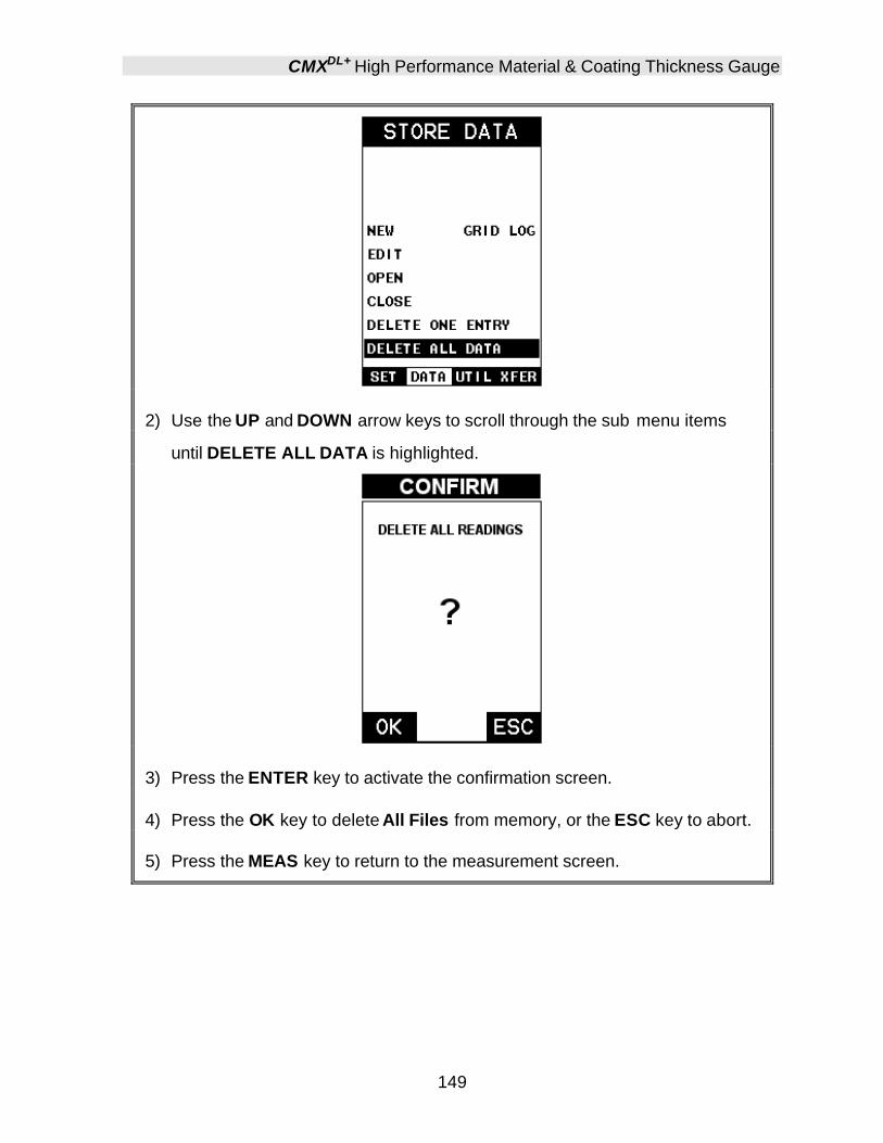
CMXDL+ High Performance Material & Coating Thickness Gauge
149
2) Use the UP and DOWN arrow keys to scroll through the sub menu items
until DELETE ALL DATA is highlighted.
3) Press the ENTER key to activate the confirmation screen.
4) Press the OK key to delete All Files from memory, or the ESC key to abort.
5) Press the MEAS key to return to the measurement screen.

Dakota Ultrasonics
150
11.6 Editing a Grid (File) Once a grid has been created and saved to memory, the user can edit the Comments or Increment Direction at a later time. The following procedures outline this process:
Editing a Grid
1) Press the MENU key once to activate the menu items tab. Press the MENU
key multiple times to tab right and the ESC key multiple times to tab left until
the DATA menu is highlighted and displaying the submenu items.
2) Use the UP and DOWN arrow keys to scroll through the sub menu items
until EDIT is highlighted.
3) Press the ENTER key to display the Edit List Box.
4) Use the UP and DOWN arrow keys to scroll through the Edit options until
NOTE or INCR. DIR is highlighted.
Note: If editing the INCR. DIR, simply use the LEFT or RIGHT arrow keys to
scroll NONE, NORTH, EAST, SOUTH, WEST for a Grid, or INC, DEC for a Seq
Log. Proceed to step 10.

CMXDL+ High Performance Material & Coating Thickness Gauge
151
5) Press the ENTER key to activate the Alpha Edit box – Only used when
editing the NOTE.
6) Use the UP, DOWN, LEFT, & RIGHT arrow keys to highlight the appropriate
alpha characters.
7) Press the ENTER key to select a character and advance to the next field of
the Comments.
8) Use the CLR key to backspace if necessary.
9) Repeat steps 6 - 8 until the Comments are completed.

Dakota Ultrasonics
152
10) Press the UP or DOWN arrow key to highlight SAVE CHANGES, and the
OK key to activate the confirmation screen.
11) Press the OK key to save the changes or the ESC key to cancel editing the
file parameters.
12) Press the MEAS key to return to the measurement screen.
11.7 Changing the active File - Open The user may have transferred grid/seq templates from a PC to the CMXDL+, or setup grids/seq using the CMXDL+ at an earlier time. The name of the currently active file is always displayed at the top of the Grid/Seq Box in measurement mode (refer to photo below). It’s not only important to recognize what file is currently active, but also be able to change the active file at any time. The following procedures outline this process:
Changing the Active File
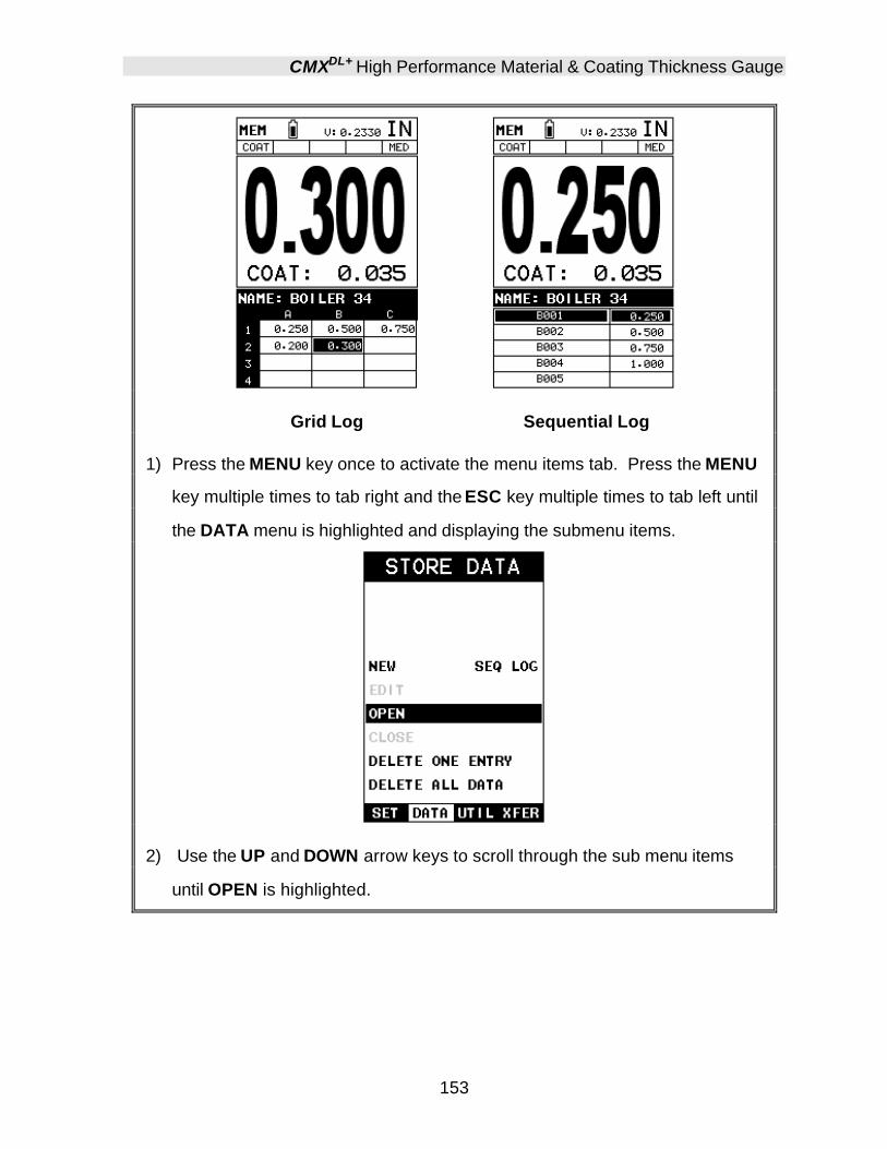
CMXDL+ High Performance Material & Coating Thickness Gauge
153
Grid Log Sequential Log
1) Press the MENU key once to activate the menu items tab. Press the MENU
key multiple times to tab right and the ESC key multiple times to tab left until
the DATA menu is highlighted and displaying the submenu items.
2) Use the UP and DOWN arrow keys to scroll through the sub menu items
until OPEN is highlighted.
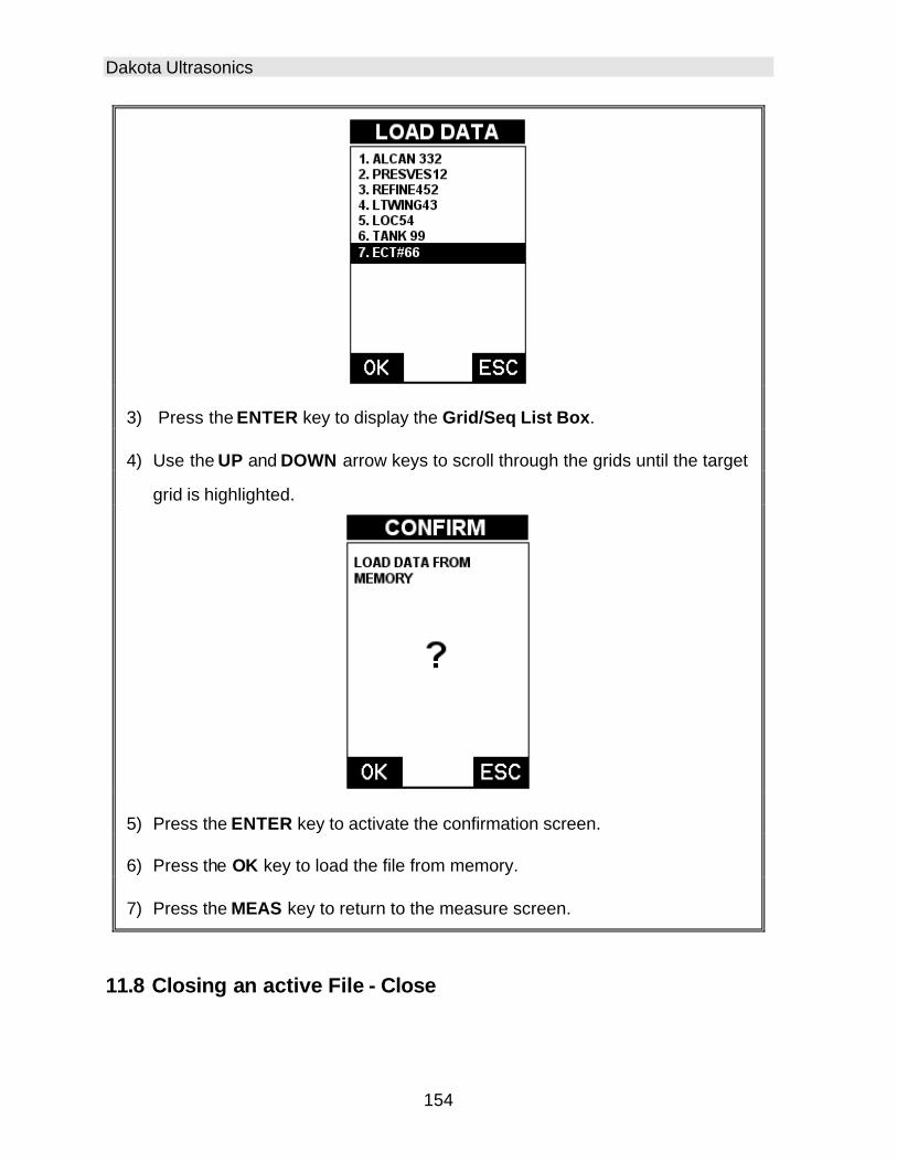
Dakota Ultrasonics
154
3) Press the ENTER key to display the Grid/Seq List Box.
4) Use the UP and DOWN arrow keys to scroll through the grids until the target
grid is highlighted.
5) Press the ENTER key to activate the confirmation screen.
6) Press the OK key to load the file from memory.
7) Press the MEAS key to return to the measure screen.
11.8 Closing an active File - Close

CMXDL+ High Performance Material & Coating Thickness Gauge
155
A user might not have a current requirement to store measurements, but a file is currently open or active and needs to be closed. The following procedures outline how to close an open or active file :
Closing an Active File
1) Press the MENU key once to activate the menu items tab. Press the MENU
key multiple times to tab right and the ESC key multiple times to tab left until
the DATA menu is highlighted and displaying the submenu items.
2) Use the UP and DOWN arrow keys to scroll through the sub menu items
until CLOSE is highlighted.

Dakota Ultrasonics
156
3) Press the ENTER key to close the active file. Note: Following the key
press, the CLOSE text will be grayed out indicating the file has been close
and is no longer active.

157
CHAPTER TWELVE SETUPS – CREATE, STORE, EDIT, & RECALL
12.1 Introduction to Setups Often times, users are faced with a variety of tasks and applications that are sometimes similar, but often times very different. With a standard thickness gauge, the user would have to recalibrate for each individual application respectively. With all the features of the CMXDL+, the number of potential applications also increases based on ability alone. This is primarily in reference to the addition of those very difficult applications, where a standard thickness gauge would not be feasible, or capable of accomplishing the tasks. The increased number of features and parameters also adds to the overall setup time, or amount of time to set up marginal applications with perfection and understanding. Because of the additional time involved, the CMXDL+ has been equipped with the ability to save these setups to memory and be recalled at any time. The CMXDL+ can store up to 64 custom setups. These setups can be bi-directionally transferred to and from a PC. Therefore, the user can save as many setups as necessary for all their individual applications requirements. This saves a great deal of time and knowledge for future inspections of the same job or project. This feature also eliminates error between two or more users during the setup and calibration process.
12.2 Opening a Setup The CMXDL+ is loaded with a number of setups from the factory. These setups can be opened, edited, and saved to any one of 64 setup locations. If a factory setup is written over, the user can simply reload the default factory setups at anytime using the utility software included with the CMXDL+. The factory setups are general setups Only. However, they may serve as an excellent starting point, requiring only minor adjustments to work for custom applications. It is recommended that user customized setups be saved to an empty location, and save the factory setups for the purpose of a general starting point. The following procedures outline how to open factory and custom setups:

Dakota Ultrasonics
158
Opening a Setup
1) Press the MENU key once to activate the menu items tab. Press the MENU
key multiple times to tab right and the ESC key multiple times to tab left until
the SETUP menu is highlighted and displaying the submenu items.
2) Use the UP and DOWN arrow keys to scroll through the sub menu items
until OPEN is highlighted.
3) Press the ENTER key to display the Setup List Box.

CMXDL+ High Performance Material & Coating Thickness Gauge
159
4) Use the UP and DOWN arrow keys to scroll through the setups until the
target setup is highlighted.
5) Press the ENTER key to activate the confirmation screen.
6) Press the OK key to load the setup from memory.
7) Press the MEAS key to return to the measure screen.
12.3 Saving a Setup Once the CMXDL+ parameters and features have be adjusted for an application, the user may elect to save these setting to a specific setup location for future use. This can potentially save time and reduce error between users. It is sometimes necessary to rename a previously saved setup, or add additional comments about a particular setup. The setup name may have been entered incorrectly, or the user needs to use the setup for a completely different project. An inspector’s name or other comments about the project may also be required for additional documentation purposes. The following procedures outline the necessary steps for saving and editing a setup:

Dakota Ultrasonics
160
Saving a Setup
1) Press the MENU key once to activate the menu items tab. Press the MENU
key multiple times to tab right and the ESC key multiple times to tab left until
the SETUP menu is highlighted and displaying the submenu items.
2) Use the UP and DOWN arrow keys to scroll through the sub menu items
until SAVE is highlighted.
3) Press the ENTER key to display the Save Setup Parameters List Box.
4) Press the UP and DOWN arrow keys to scroll the Name and Note
parameters.
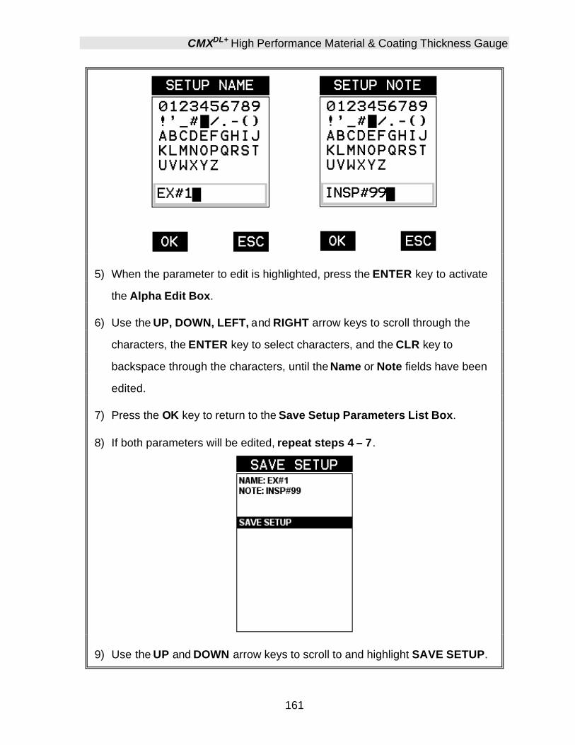
CMXDL+ High Performance Material & Coating Thickness Gauge
161
5) When the parameter to edit is highlighted, press the ENTER key to activate
the Alpha Edit Box.
6) Use the UP, DOWN, LEFT, and RIGHT arrow keys to scroll through the
characters, the ENTER key to select characters, and the CLR key to
backspace through the characters, until the Name or Note fields have been
edited.
7) Press the OK key to return to the Save Setup Parameters List Box.
8) If both parameters will be edited, repeat steps 4 – 7.
9) Use the UP and DOWN arrow keys to scroll to and highlight SAVE SETUP.
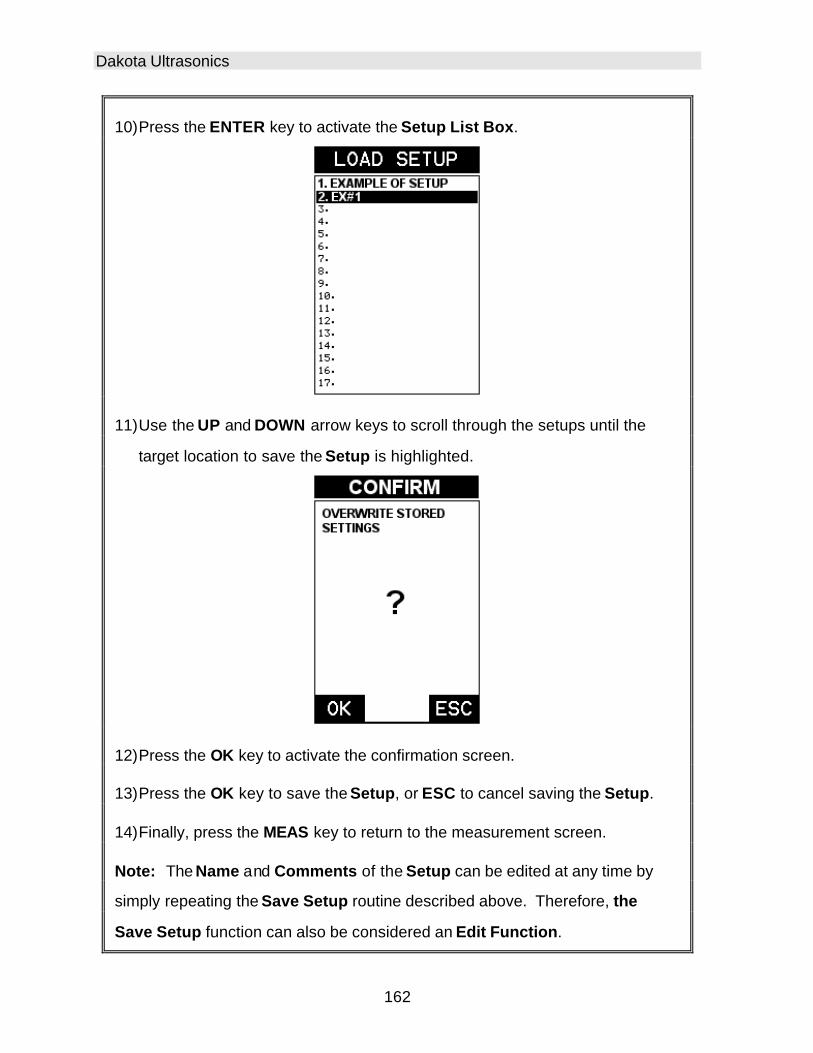
Dakota Ultrasonics
162
10) Press the ENTER key to activate the Setup List Box.
11) Use the UP and DOWN arrow keys to scroll through the setups until the
target location to save the Setup is highlighted.
12) Press the OK key to activate the confirmation screen.
13) Press the OK key to save the Setup, or ESC to cancel saving the Setup.
14) Finally, press the MEAS key to return to the measurement screen.
Note: The Name and Comments of the Setup can be edited at any time by
simply repeating the Save Setup routine described above. Therefore, the
Save Setup function can also be considered an Edit Function.

CMXDL+ High Performance Material & Coating Thickness Gauge
163
12.4 Deleting a Saved Setup This option allows a user to delete setup files that were previously saved and no longer needed. It’s a simple feature to allow the user to do a bit of “house cleaning”.
Deleting a Setup
1) Press the MENU key once to activate the menu items tab. Press the MENU
key multiple times to tab right and the ESC key multiple times to tab left until
the SETUP menu is highlighted and displaying the submenu items.
2) Use the UP and DOWN arrow keys to scroll through the sub menu items
until DELETE is highlighted.

Dakota Ultrasonics
164
3) Press the ENTER key to display the Setups List.
4) Press the UP and DOWN arrow keys to scroll to the Setup Name.
5) When the Setup Name is highlighted, press the ENTER key to display the
confirmation screen.
6) Press the OK key to delete the Setup File.
7) Finally, press the MEAS key to return to the measurement screen.
12.5 Using the Default Setup The default setup feature was added to the CMXDL+ to use, as a last resort, if there are no setups stored in the gauge –factory or otherwise. The only time this might possibly occur is if the setup file in the CMXDL+ was somehow corrupted, and the user does not have access to a computer to re-load the factory setups back into the CMXDL+. This gives the user the ability to load and modify a basic setup as follows: Note: The default file contains no probe zero data. Therefore, a zero must be performed after loading. Also, the default setup can be loaded when using the flaw mode feature, to eliminate the probe zero delay value, and start at the initial pulse or zero.
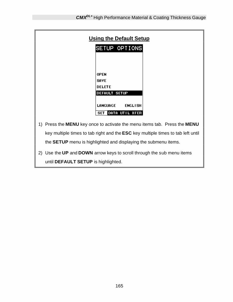
CMXDL+ High Performance Material & Coating Thickness Gauge
165
Using the Default Setup
1) Press the MENU key once to activate the menu items tab. Press the MENU
key multiple times to tab right and the ESC key multiple times to tab left until
the SETUP menu is highlighted and displaying the submenu items.
2) Use the UP and DOWN arrow keys to scroll through the sub menu items
until DEFAULT SETUP is highlighted.
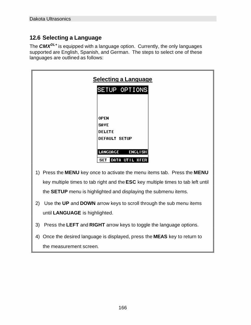
Dakota Ultrasonics
166
12.6 Selecting a Language The CMXDL+ is equipped with a language option. Currently, the only languages supported are English, Spanish, and German. The steps to select one of these languages are outlined as follows:
Selecting a Language
1) Press the MENU key once to activate the menu items tab. Press the MENU
key multiple times to tab right and the ESC key multiple times to tab left until
the SETUP menu is highlighted and displaying the submenu items.
2) Use the UP and DOWN arrow keys to scroll through the sub menu items
until LANGUAGE is highlighted.
3) Press the LEFT and RIGHT arrow keys to toggle the language options.
4) Once the desired language is displayed, press the MEAS key to return to
the measurement screen.

167
CHAPTER THIRTEEN USING THE UTILITY SOFTWARE
13.1 Computer System Requirements DakView will run on many different operating systems: Windows 98 (1st or 2nd edition), Windows NT 4.0 with Service Pack 5, Windows ME, Windows XP, Windows 2000 Professional, Windows 2000 Server, or Windows 2000 Advanced Server operating systems running on Intel or AMD hardware. A Pentium 166MHz or faster processor with at least 32 megabytes of physical RAM is required. You should have 40 megabytes of free disk space before attempting to install DakView. DakView requires an available communications port in order to transfer data to and from the CMXDL+. DakView supports COM1, COM2, COM3, and COM4.
USB to Serial Converter
Some newer laptop computers do not have standard serial ports. In this case it is possible to use a USB to Serial converter. If a serial to USB cable is needed, Contact Dakota Ultrasonics (pt# N-402-0510).
13.2 Installing DakView DakView comes on a CD-ROM with an automatic installer program. Place the CD in your computer’s CD tray and close the door. Open the CD-ROM by double clicking on the My Computer ICON, then double click on the CD. Finally, double click on the SETUP icon to begin the installation. Refer to the help section in DakView software for the complete operating manual, setup, and operation.

Dakota Ultrasonics
168
13.3 Using the XFER menu (CMXDL+) The XFER menu of the CMXDL+ will be used in conjunction with the DakView PC software. The steps below outline the procedure for accessing the XFER menu and basic operation as follows:
Accessing and Using the XFER Menu
1) Press the MENU key once to activate the menu items tab. Press the MENU
key multiple times to tab right, and the ESC key multiple times to tab left,
until the XFER menu is highlighted and displaying the submenu items.
2) Use the UP and DOWN arrow keys to scroll through the sub menu items
until the desire option is highlighted.
3) Press the ENTER key to activate the option selected.
4) Once the Backup or Restore function has been completed, press the
MEAS key once to return to the menu items, o r twice to return to the
measurement mode.
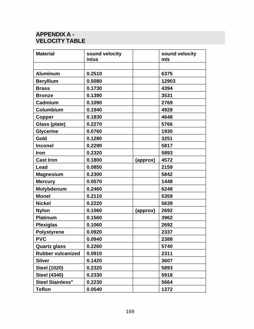
169
APPENDIX A - VELOCITY TABLE
Material sound velocity in/us
sound velocity m/s
Aluminum 0.2510 6375 Beryllium 0.5080 12903 Brass 0.1730 4394 Bronze 0.1390 3531 Cadmium 0.1090 2769 Columbium 0.1940 4928 Copper 0.1830 4648 Glass (plate) 0.2270 5766 Glycerine 0.0760 1930 Gold 0.1280 3251 Inconel 0.2290 5817 Iron 0.2320 5893 Cast Iron 0.1800 (approx) 4572 Lead 0.0850 2159 Magnesium 0.2300 5842 Mercury 0.0570 1448 Molybdenum 0.2460 6248 Monel 0.2110 5359 Nickel 0.2220 5639 Nylon 0.1060 (approx) 2692 Platinum 0.1560 3962 Plexiglas 0.1060 2692 Polystyrene 0.0920 2337 PVC 0.0940 2388 Quartz glass 0.2260 5740 Rubber vulcanized 0.0910 2311 Silver 0.1420 3607 Steel (1020) 0.2320 5893 Steel (4340) 0.2330 5918 Steel Stainless" 0.2230 5664 Teflon 0.0540 1372

Dakota Ultrasonics
170
Tin 0.1310 3327 Titanium 0.2400 6096 Tungsten 0.2040 5182 Uranium 0.1330 3378 Water 0.0580 1473 Zinc 0.1660 4216 Zirconium 0.1830 4648

171
APPENDIX B - SETUP LIBRARY
Num Name Comment 1 Gn/AGC Velocity 1 Enter Custom Name 2 … 3 … 4 … 5 … 6 … … …

172
WARRANTY INFORMATION
• Warranty Statement •
Dakota Ultrasonics warrants the CMX DL+ against defects in materials and workmanship for a period of two years from receipt by the end user. Additionally, Dakota Ultrasonics warrants transducers and accessories against such defects for a period of 90 days from receipt by the end user. If Dakota Ultrasonics receives notice of such defects during the warranty period, Dakota Ultrasonics will either, at its option, repair or replace products that prove to be defective.
Should Dakota Ultrasonics be unable to repair or replace the product within a reasonable amount of time, the customer's alternative exclusive remedy shall be refund of the purchase price upon return of the product.
• Exclusions •
The above warranty shall not apply to defects resulting from: improper or inadequate maintenance by the customer; unauthorized modification or misuse; or operation outside the environmental specifications for the product.
Dakota Ultrasonics makes no other warranty, either express or implied, with respect to this product. Dakota Ultrasonics specifically disclaims any implied warranties of merchantability or fitness for a particular purpose. Some states or provinces do not allow limitations on the duration of an implied warranty, so the above limitation or exclusion may not apply to you. However, any implied warranty of merchantability or fitness is limited to the five-year duration of this written warranty.
This warranty gives you specific legal rights, and you may also have other rights which may vary from state to state or province to province.
• Obtaining Service During Warranty Period •
If your hardware should fail during the warranty period, contact Dakota Ultrasonics and arrange for servicing of the product. Retain proof of purchase in order to obtain warranty service.
For products that require servicing, Dakota Ultrasonics may use one of the following methods:
- Repair the product - Replace the product with a re-manufactured unit - Replace the product with a product of equal or greater performance - Refund the purchase price.
• After the Warranty Period •
If your hardware should fail after the warranty period, contact Dakota Ultrasonics for details of the services available, and to arrange for non-warranty service.

MATERIAL SAFETY DATA SHEETN/A = not applicable or not available (To comply with 29 CFR 1910.1200)
SECTION 1 – PRODUCT IDENTIFICATION
Product Name: SOUNDSAFEGeneric Name: Ultrasonic CouplantManufacturer: Sonotech, Inc. 774 Marine Dr., Bellingham, WA 98225 (360) 671-9121
NFPA Hazardous MaterialsIdentification System (est)Health……………………0Flammability…………….0Reactivity………………..0
SECTION 2 – HAZARDOUS INGREDIENTS
This material does not contain any ingredients havingknown health hazards in concentrations greater than 1%.
This material does not contain any known or suspectedcarcinogens.
SECTION 3 – PHYSICAL DATA(nominal)
Boiling Point: >220°F pH: 7.35 – 7.9Freezing Point: <20°F Acoustic Imp.: 1.726x10⁶
Vapor Pressure: N/A Vapor Density: N/AEvaporation Rate: N/A Specific Gravity: >1.02Solubility in Water: completeAppearance and Odor: water white, opaque gel; bland odor
SECTION 4 – FIRE AND EXPLOSIONHAZARD DATA
Flash Point: noneUpper Exposure Limit: noneLower Exposure Limit: noneSpecial Fire Fighting Procedures: N/AExtinguishing media: N/AUnusual Fire and Explosion Hazards: none
SECTION 5 – REACTIVITY DATA
Stability: StableConditions to Avoid: noneIncompatibility (Materials to Avoid): none knownHazardous Polymerization: will not occurHazardous Decomposition or Byproducts: none known
SECTION 6 – HEALTH HAZARD AND FIRST AID DATA
Routes of Entry:1
Skin: not likely Ingestion: not normallyEyes: not normally Inhalation: noEffects of Overexposure: Acute: May cause temporary
eye irritationChronic: none expected
First Aid Procedures:Skin: Remove with water if desired.Eyes: Flush with water for 15 minutes.Ingestion: For large quantities, induce vomiting and
call a physician.Inhalation: N/A
SECTION 7 – STORAGE AND HANDLINGINFORMATION
Precautions to be taken in handling and storage: Storebetween 20°F and 120°F. Spills are slippery and shouldbe cleaned up immediately.Steps to be taken in case material is released or spilled:Pick up excess for disposal. Clean with water.Waste disposal method: Dispose of in accordance withfederal, state, and local regulations.
SECTION 8 – CONTROL MEASURES
Respiratory Protection: not requiredVentilation: not requiredProtective Gloves: on individuals demonstrating
sensitivity to SOUNDSAFEEye Protection: as required by working conditionsOther Protective Equipment: not required
1SOUNDSAFE contains only food grade and cosmetic grade ingredients.
Toll Free: 1-800-458-4254
SONOTECH, INC.774 Marine Dr., Bellingham, WA 98225
Telephone: (360) 671-9121 Fax: (360) 671-9024
