operational semantics applied to model driven engineering · operational semantics applied to model...
TRANSCRIPT

T.J.L. Wolterink
Operational Semantics Appliedto Model Driven Engineering
Thesis for the degree of
Master Of Science
(Computer Science, Track Software Engineering)
SupervisorsDr. I. Kurtev
Dr.Ir. K.G. van den Berg
A. Goknil
Faculty of Electrical Engineering,Mathematics and Computer Science


Abstract
Model driven engineering (MDE) is an approach to software engineering and isused more and more in both research and practice. It provides a higher levelof abstraction and supports domain specific languages (DSLs). There is muchresearch done on the static aspects of MDE and most examples deal with staticmodels. However DSLs are also used more and more to model the behaviour ofa specific domain. These DSLs often lack clear and formal semantics.Some approaches have been taken to define the semantics of modelling lan-guages. These approaches differ in their pragmatic and formal aspects. Noneof these approaches are built upon the existing formalism of Structural Oper-ational Semantics (SOS). SOS specifies the semantics of a language based onrules. These rules define a transition system in which the states are extendedASTs. This research adapts SOS in such a way that it can be applied on MDEmodels instead of ASTs. SOS seems to be a good candidate for specifying the se-mantics of modelling languages because it is based on the structure of programswhich are well defined in a metamodel of a modelling language.The main contribution of this thesis consists of a Semantic Language, SemLang,which is based on SOS. The Semantic Language is defined using an MDE ap-proach: SemLang is defined as a metamodel. It closely resembles SOS but hassome differences that make it suitable for defining the semantics of a DSL basedon metamodels. A SemLang model is a set of rules that defines a transitionsystem where the states are extended models. SemLang has constructs to dealwith lists and graph structures. The Semantic Language is formalized by alteringthe existing formalizations of SOS.Another result of this research is a tool which supports simulating and debug-ging of models given their semantics description in SemLang. The tool is builtupon the Eclipse framework and provides a graphical user interface. As a proofof concept we apply our approach on some simple functional and imperativelanguages. We also show that this approach can be used on DSLs like ActivityDiagrams and Petri Nets.
i


Acknowledgements
All the work done for this thesis could not be done without the help, encour-agement and support of numerous people. Different people supported me indifferent ways and this combination ensured a pleasant working environment.At first I want to thank my first supervisor, Ivan Kurtev, for his guidancebefore and during the project. Without his help I would have had difficultydiscovering the interesting world of academic research. I also admire his calmnessand informality, even when he had to supervise numerous other graduationstudents. I would also thank my other supervisors, Arda Goknil and Klaas vanden Berg, for taking the time to read and review my thesis.Secondly I want to thank my family; my brothers and especially my parents forsupporting me throughout my years at the university. Even though it is difficultfor them to understand the work done in my thesis I am sure they will try toread some parts of this thesis. Especially this paragraph.Another important ingredient were my fellow students from room 5066 (for-merly 5070). The working atmosphere in that room was great on they providedhelp when needed. The discussions during lunch and during work were bothentertaining and occasionally also informative.At last I want to thank anybody that I forgot to thank. This includes the authorsof the interesting papers I have read and of course anybody that showed interestin my work as a master student.
Tjerk Wolterink, August 2009, Enschede
”The sciences do not try to explain, they hardly even try to interpret, theymainly make models. By a model is meant a mathematical construct which,
with the addition of certain verbal interpretations, describes observedphenomena. The justification of such a mathematical construct is solely and
precisely that it is expected to work.”
John Von Neumann (1903 - 1957)
iii


Table of Contents
Abstract i
Acknowledgements iii
1 Introduction 11.1 Background . . . . . . . . . . . . . . . . . . . . . . . . . . . . . . 11.2 Problem Statement . . . . . . . . . . . . . . . . . . . . . . . . . . 11.3 Research Objectives . . . . . . . . . . . . . . . . . . . . . . . . . 21.4 Contributions . . . . . . . . . . . . . . . . . . . . . . . . . . . . . 31.5 Outline . . . . . . . . . . . . . . . . . . . . . . . . . . . . . . . . 4
2 Basic Concepts 72.1 Introduction . . . . . . . . . . . . . . . . . . . . . . . . . . . . . . 72.2 Model Driven Engineering . . . . . . . . . . . . . . . . . . . . . . 7
2.2.1 Models and Metamodels . . . . . . . . . . . . . . . . . . . 72.2.2 Model Definition . . . . . . . . . . . . . . . . . . . . . . . 92.2.3 Metamodel Definition . . . . . . . . . . . . . . . . . . . . 9
2.3 MDE Approaches . . . . . . . . . . . . . . . . . . . . . . . . . . . 102.3.1 Object Management Group . . . . . . . . . . . . . . . . . 102.3.2 MS Software Factory Tools . . . . . . . . . . . . . . . . . 102.3.3 Eclipse Modelling Framework . . . . . . . . . . . . . . . . 11
2.4 Domain Specific Languages . . . . . . . . . . . . . . . . . . . . . 112.4.1 MetaModel . . . . . . . . . . . . . . . . . . . . . . . . . . 122.4.2 Semantics . . . . . . . . . . . . . . . . . . . . . . . . . . . 12
2.5 Semantics of Languages . . . . . . . . . . . . . . . . . . . . . . . 122.5.1 General Theory . . . . . . . . . . . . . . . . . . . . . . . . 122.5.2 Approaches . . . . . . . . . . . . . . . . . . . . . . . . . . 13
2.6 Structural Operational Semantics . . . . . . . . . . . . . . . . . . 142.6.1 Semantic Domain . . . . . . . . . . . . . . . . . . . . . . . 142.6.2 Rules . . . . . . . . . . . . . . . . . . . . . . . . . . . . . 142.6.3 Example . . . . . . . . . . . . . . . . . . . . . . . . . . . . 152.6.4 Transition System Specification . . . . . . . . . . . . . . . 162.6.5 SOS Styles . . . . . . . . . . . . . . . . . . . . . . . . . . 16
2.7 Approaches to defining the Semantics of Modelling Languages . . 172.7.1 Introduction . . . . . . . . . . . . . . . . . . . . . . . . . 172.7.2 Model Transformations . . . . . . . . . . . . . . . . . . . 172.7.3 Graph Transformations . . . . . . . . . . . . . . . . . . . 182.7.4 MDE with Maude . . . . . . . . . . . . . . . . . . . . . . 182.7.5 Simulation in the Topcased Toolkit . . . . . . . . . . . . . 182.7.6 Semantic Anchoring . . . . . . . . . . . . . . . . . . . . . 19
2.8 Conclusion . . . . . . . . . . . . . . . . . . . . . . . . . . . . . . 19
3 An SOS based Semantic Language DSL 213.1 Introduction . . . . . . . . . . . . . . . . . . . . . . . . . . . . . . 213.2 SOS for Expressions . . . . . . . . . . . . . . . . . . . . . . . . . 22
3.2.1 Metamodel . . . . . . . . . . . . . . . . . . . . . . . . . . 223.2.2 Semantics . . . . . . . . . . . . . . . . . . . . . . . . . . . 233.2.3 Example Simulation . . . . . . . . . . . . . . . . . . . . . 25
v

TABLE OF CONTENTS
3.3 Introducing the Store . . . . . . . . . . . . . . . . . . . . . . . . 273.3.1 MetaModel . . . . . . . . . . . . . . . . . . . . . . . . . . 273.3.2 Semantics . . . . . . . . . . . . . . . . . . . . . . . . . . . 293.3.3 Example Simulation . . . . . . . . . . . . . . . . . . . . . 32
3.4 Introducing the Environment . . . . . . . . . . . . . . . . . . . . 343.4.1 MetaModel . . . . . . . . . . . . . . . . . . . . . . . . . . 343.4.2 Semantics . . . . . . . . . . . . . . . . . . . . . . . . . . . 373.4.3 Example Simulation . . . . . . . . . . . . . . . . . . . . . 41
3.5 Supporting Graph Structures: Activity Diagrams . . . . . . . . . 443.5.1 MetaModel . . . . . . . . . . . . . . . . . . . . . . . . . . 443.5.2 Semantics . . . . . . . . . . . . . . . . . . . . . . . . . . . 453.5.3 Example Simulation . . . . . . . . . . . . . . . . . . . . . 50
3.6 Supporting Graph Structures: Petri Nets . . . . . . . . . . . . . . 513.6.1 MetaModel . . . . . . . . . . . . . . . . . . . . . . . . . . 513.6.2 Semantics . . . . . . . . . . . . . . . . . . . . . . . . . . . 533.6.3 Example Simulation . . . . . . . . . . . . . . . . . . . . . 55
3.7 Conclusion . . . . . . . . . . . . . . . . . . . . . . . . . . . . . . 57
4 Formalizing the Semantic Language DSL 594.1 Introduction . . . . . . . . . . . . . . . . . . . . . . . . . . . . . . 594.2 The Transition System . . . . . . . . . . . . . . . . . . . . . . . . 59
4.2.1 Models as graphs . . . . . . . . . . . . . . . . . . . . . . . 594.2.2 State representation . . . . . . . . . . . . . . . . . . . . . 61
4.3 The Transition System Specification . . . . . . . . . . . . . . . . 624.3.1 SemLang Models . . . . . . . . . . . . . . . . . . . . . . 624.3.2 Proving Transitions . . . . . . . . . . . . . . . . . . . . . 64
4.4 Conclusion . . . . . . . . . . . . . . . . . . . . . . . . . . . . . . 66
5 Semantic Engine: Tool for the Semantic Language 675.1 Introduction . . . . . . . . . . . . . . . . . . . . . . . . . . . . . . 675.2 Requirements . . . . . . . . . . . . . . . . . . . . . . . . . . . . . 675.3 Architecture . . . . . . . . . . . . . . . . . . . . . . . . . . . . . . 68
5.3.1 High Level Architecture . . . . . . . . . . . . . . . . . . . 685.3.2 The Semantic Language . . . . . . . . . . . . . . . . . . . 695.3.3 Architecture of the Semantic Engine . . . . . . . . . . . . 695.3.4 Architecture of the User Interface . . . . . . . . . . . . . . 70
5.4 Quality attributes . . . . . . . . . . . . . . . . . . . . . . . . . . 735.5 Conclusion . . . . . . . . . . . . . . . . . . . . . . . . . . . . . . 74
6 Evaluation 756.1 Introduction . . . . . . . . . . . . . . . . . . . . . . . . . . . . . . 756.2 Expressiveness . . . . . . . . . . . . . . . . . . . . . . . . . . . . 756.3 Comparison to Existing Approaches . . . . . . . . . . . . . . . . 76
6.3.1 Model Transformations . . . . . . . . . . . . . . . . . . . 766.3.2 Graph Transformations . . . . . . . . . . . . . . . . . . . 766.3.3 MDE with Maude . . . . . . . . . . . . . . . . . . . . . . 776.3.4 Simulation in the Topcased Toolkit . . . . . . . . . . . . . 786.3.5 Semantics Anchoring . . . . . . . . . . . . . . . . . . . . . 78
6.4 Conclusion . . . . . . . . . . . . . . . . . . . . . . . . . . . . . . 78
vi

TABLE OF CONTENTS
7 Conclusions 797.1 Introduction . . . . . . . . . . . . . . . . . . . . . . . . . . . . . . 797.2 Summary . . . . . . . . . . . . . . . . . . . . . . . . . . . . . . . 797.3 Answers to the Research Questions . . . . . . . . . . . . . . . . . 80
7.3.1 Limitations . . . . . . . . . . . . . . . . . . . . . . . . . . 817.4 Future Work . . . . . . . . . . . . . . . . . . . . . . . . . . . . . 82
7.4.1 Concurrency & Interactivity . . . . . . . . . . . . . . . . . 827.4.2 Rule Extensions . . . . . . . . . . . . . . . . . . . . . . . 827.4.3 Potential Applications . . . . . . . . . . . . . . . . . . . . 83
A Appendix A: Compact Disc 89
vii


List of Figures
1.1 Dependencies between chapters . . . . . . . . . . . . . . . . . . . 5
2.1 Layers in MDE . . . . . . . . . . . . . . . . . . . . . . . . . . . . 8
3.1 SemLang describes the semantics of a DSL . . . . . . . . . . . . 213.2 Expression language metamodel . . . . . . . . . . . . . . . . . . . 223.3 Expression language sample model . . . . . . . . . . . . . . . . . 233.4 Semantic SOS rules for the expression language . . . . . . . . . . 243.5 Execution states after applying the rules to the example model . 273.6 Simple imperative language metamodel . . . . . . . . . . . . . . 283.7 Sample model as a graph . . . . . . . . . . . . . . . . . . . . . . 293.8 SOS rules for binary expressions . . . . . . . . . . . . . . . . . . 303.9 Rules for the Seq command . . . . . . . . . . . . . . . . . . . . . 313.10 Store definition and rules for Assign and Var . . . . . . . . . . 323.11 First transition of the sample model . . . . . . . . . . . . . . . . 333.12 Last transition of the sample model . . . . . . . . . . . . . . . . 343.13 Functional language metamodel . . . . . . . . . . . . . . . . . . . 353.14 Sample model as a graph . . . . . . . . . . . . . . . . . . . . . . 363.15 Evaluation of the definitions . . . . . . . . . . . . . . . . . . . . . 383.16 Evaluation of the SeqDef to an environment . . . . . . . . . . . . 413.17 Reading a variable from the environment . . . . . . . . . . . . . 423.18 Concrete visual model of an Activity Diagram . . . . . . . . . . . 443.19 Activity Diagram language metamodel . . . . . . . . . . . . . . . 453.20 Object model of an Activity Diagram . . . . . . . . . . . . . . . 463.21 Example state transition for the example Activity Diagram . . . 503.22 Concrete visual model of an example Petri Net . . . . . . . . . . 513.23 Petri Net language metamodel . . . . . . . . . . . . . . . . . . . 523.24 Example Petri Net model . . . . . . . . . . . . . . . . . . . . . . 523.25 Petri Net example simulation . . . . . . . . . . . . . . . . . . . . 533.26 Petri Net example model simulation . . . . . . . . . . . . . . . . 56
5.1 Component Diagram of the Tool . . . . . . . . . . . . . . . . . . 685.2 Class Diagram of the Semantic Engine . . . . . . . . . . . . . . . 695.3 Class Diagram of the UI . . . . . . . . . . . . . . . . . . . . . . . 715.4 The state graph view . . . . . . . . . . . . . . . . . . . . . . . . . 715.5 The transition stack view . . . . . . . . . . . . . . . . . . . . . . 725.6 The views in the user interface . . . . . . . . . . . . . . . . . . . 72
ix


List of Abbreviations
ASM Abstract State Machine
AST Abstract Syntax Tree
BNF Backus–Naur Form
DSL Domain Specific Language
DSM Domain Specific Modelling
EMF Eclipse Modelling Foundation
EMOF Essential Meta Object Facility
GME Generic Modelling Environment
GMF Graphical Modelling Framework
GPL General Purpose Language
LTS Labelled Transition System
LTTS Labelled Terminal Transition System
MDA Model Driven Architecture
MDE Model Driven Engineering
MOF Meta Object Facility
MSOS Modular Structural Operational Semantics
OCL Object Contraint Language
OMG Object Management Group
QVT Query View Transformation
RCP Rich Client Platform
SemLang Semantic Language
SI Structural Induction
SOS Structural Operational Semantics
SWT Standard Widget Toolkit
TCS Textual Concrete Syntax
TSS Transition System Specification
UML Unified Modelling Language
XML Extended Markup Language
xi


1Introduction
1.1 Background
Modelling is used to understand processes and systems in the real world. Dif-ferent formal and informal modelling languages have been introduced. This in-cludes petri nets, state charts and UML . Programming languages and humanlanguages on the other hand can also be seen as modelling languages. Theselanguages differ in their formality, ambiguity and application domain.A new approach to software development is Model Driven Engineering (MDE)[Ken02]. MDE raises the level of abstraction by introducing metametamodels[B04]. When defining a language without MDE one first specifies the conceptsof the language (either mathematically or by using a syntax specification). Thenone defines the semantics of the language in either an informal or formal way.With MDE one specifies a modelling language by creating a metamodel whichdescribes the structures of the models. A textual or graphical concrete syn-tax can be created if needed (for example with TCS [JBK06]). However, thereis no commonly established way of specifying the semantics of an executablemodelling language. A simple approach is to use code generation, however, thisapproach is rather informal. Some research is done in the area of formal seman-tics for MDE; different authors apply different formal frameworks to solve thisissue [SW08, Hec06, BH02, RRDV07, RV07, CCG+08, VPF+06, CSAJ05].No research to adapt the Structural Operational Semantics (SOS) [Plo81] for-malism to MDE is done in the past. This formalism seems a fruitful approach forMDE because the SOS formalism is built upon the structure of a modelling lan-guage. MDE has metamodels which clearly define the structure of a modellinglanguage.
1.2 Problem Statement
Adapting SOS in order to make it useful in an MDE context is not straightforward. The first problem is the incompatibility between SOS and MDE; SOSis applied on trees while MDE models are graph structures. However, we thinkit is possible to apply SOS, with some changes, to MDE. This leads to thefollowing research question:
Can SOS be adapted and applied successfully on MDE?
The adapted SOS will be called the Semantic Language (abbreviated to Sem-Lang). The main research questions can be divided into several sub-questions
1

CHAPTER 1. INTRODUCTION
that need to be answered. The first sub-question is:
MDE models are graph structures but SOS is based on trees. Can SOS be adaptedin order to make it suitable for using it with graph structures?
The main problem is the differences between the programs in SOS and MDE. InSOS the program is represented as a (extended) abstract syntax tree. In MDE,however, the program is represented as a model which is basically a more generalgraph structure. This difference is a problem that needs to be solved.
SOS is based on the abstract syntax description of languages, how can SOS beadapted to deal with metamodels?
The rules in SOS refer to the abstract syntax of a language in order to transformlanguage structures to new language structures. In MDE metamodels have thesame role as the abstract syntax description. This difference requires changes toSOS in order to apply it to MDE.
The semantic domain of SOS is a labelled transition system in which the statesare trees. How can we change the semantic domain in order to make it suitablefor models?
A semantic domain is a well known mathematical domain in which the semanticsis expressed (for more details see section 2.5). The semantic domain of SOS isspecified in different papers [Plo81, AFV01, Mos04]. The semantic domain ofSOS is not suitable for defining the semantics of MDE modelling languages.It is of course difficult to test whether the main hypothesis is met in the endof the thesis. Therefore we limit the test to a set of DSLs which have differentsemantic properties. This includes imperative and functional languages but alsograph like languages like petri nets and state charts. Another important resultis to point out what the difficulties are when applying SOS to MDE.
1.3 Research Objectives
The research objectives are listed below. A description of each objective is given.
• Adapt SOS in order to make it suitable for MDE
The objective of this research is to adapt SOS in order to make it usefulfor MDE. This includes adapting the SOS formalism and specifying howit is related to the metamodel of the modelling language. The goal is toshow that MDE and SOS are a good match by proof of concept.
• Introduce a new semantic language which is based on SOS
The main work in order to reach that objective is to develop a new se-mantic language based on SOS which can be used to define the semanticsof modelling languages. The focus should be on the pragmatic aspects.
• Provide a partial formalization of the new language
In order to provide some mathematical foundation for our work an impor-tant contribution is the partial formalization of the new language. Thisformalization can be built upon existing formalizations of SOS.
• Implement a tool that support simulating and debugging of models
2

1.4. CONTRIBUTIONS
Another major objective is the development of a tool. The tool is needed inorder to make the SOS based language useful. The tool should be able toload and simulate models given their semantics description. The additionof a graphical user interface is also desirable.
• Validate the research by applying the new language on some example DLSs
The new language will be applied on several example DSLs in order toillustrate that the research goal is met. These example DSLs should coverdifferent language types, like imperative and functional language. Part ofthis objective is to apply the new language on graph based languages likeActivity Diagrams.
1.4 Contributions
Each objective resulted in at least one contribution. The contributions are listedbelow with a description accompanying each contribution.
• A new Semantic Language is introduced
This work introduces a Semantic Language which can be used to specifythe dynamic semantics of modelling languages. The Semantic Languagebuilds upon SOS and is therefore greatly influenced by the structure ofSOS rules. However, the Semantic Language has features that make it suit-able for defining the semantics of modelling language defined using MDEconcepts. The Semantic Language itself also follows the MDE principles;the language is defined as a DSL. It comes with a concrete syntax whichmakes it easy to define the semantics of a DSL.
• A partial formalization of the Semantic Language is given
The known semantics of SOS are adapted in order to provide the mathe-matical foundations for the Semantic Language. The main differences arein the semantic domain and in the rules. The states in the semantic do-main of the Semantic Language are basically extended graph structures.The rules consist of terms that refer to metamodel elements instead ofAST elements.
• A solution to the problem of applying SOS with graphs
The main difference between the Semantic Language and plain SOS isthat the Semantic Language is suitable for defining the semantics of graphbased models. The main changes that were needed was the introductionof a breath-first-search based copy algorithm. This copy algorithm en-sures that nodes are not copied more that once, thus preventing infiniterecursion.
• An implementation of a graphical tool called Semantic Engine
Another major part of the work done for this thesis is the implementationof a tool called the Semantic Engine. This tool is an implementation ofthe Semantic Language and it provides a complementary graphical userinterface in order to simulate models for which the semantics are specified.The tool also provides debugging functions like state inspection, step-by-step simulation and a visualization of transition proof trees.
3

CHAPTER 1. INTRODUCTION
• The Semantic Language is applied to several example DSLs
Another contribution is the application of the Semantic Language to sev-eral example DSLs. This is done as a proof of concept. The DSLs covera range of language types; functional and imperative languages but alsograph based languages like Petri Nets and Activity Diagrams.
Different approaches for defining the semantics of DSLs already existed. How-ever, nobody tried adapting SOS in order to make it suitable for defining thesemantics of DSLs. This thesis provides a first approach in combining SOS andMDE.
1.5 Outline
Chapter 2 introduces all basic concepts that are used in this thesis. It explainsMDE and highlights some approaches in the MDE field. Secondly the use of do-main specific languages is explained. The remaining of the chapter focuses on thesemantics of languages. The structural operational semantics (SOS) approachto semantics is explained in more depth.Chapter 2.7 takes a look at the current approaches to specifying the semanticsof models in an MDE context. Some current approaches are explained. Theseapproaches must be explained to place this thesis into a proper context, it alsoprovides some comparison material.Chapter 3 introduces a DSL named SemLang which can be used to specifythe semantics of other DSLs. The DSL is based on SOS but has some nicefeatures that make it suitable in an MDE context. The chapter also providessome example DSLs on which SemLang is applied.Chapter 4 formalizes the DSL SemLang DSL. It builds upon existing formal-izations of SOS. The formalization provides a solid mathematical framework onwhich the SemLang DSL is built.Part of this research was also the implementation of a tool which could simulateDSLs for which the semantics are defined using SemLang. The tool require-ments, architecture and evaluation can be found in chapter 5.The evaluation of the work done in this thesis can be found in chapter 6. Ourapproach is compared to the existing approaches for defining semantics of mod-els. The conclusion of this paper is in the last chapter (chapter 7) in which theanswers to the research questions can be found.This paper can be read in different ways. To accommodate the reader a diagramof the dependencies between the chapters is given in figure 1.1. The Basic Con-cepts chapter may be skipped if the reader is already familiar with MDE andSOS concepts.
4

1.5. OUTLINE
Figure 1.1: Dependencies between chapters
5


2Basic Concepts
2.1 Introduction
The main aim of the thesis is to introduce a framework which can be used todefine the semantics of modelling languages in a formal way, therefore it is im-portant to investigate the basic concepts in this area. First the main conceptsin the Model Driven Engineering (MDE)[Ken02] field are explained. The con-cepts of model and metamodel and the relations between them are explained.Subsequently some approaches to MDE are explained and their differences andsimilarities are discussed. In section 2.4 domain specific languages (DSLs) andtheir relation to the MDE field are covered. Novices in the MDE field may skipthe first two sections.In the end the current state of the art in the specification of the semantics ofprogramming languages is explored. The knowledge in this area can be usedto specify semantics for modelling languages. The next chapter (chapter 2.7)explores how the semantics of DSLs are currently specified.
2.2 Model Driven Engineering
Model Driven Engineering (MDE) provides a higher level of abstraction withrespect to software engineering. Analogous to the principle everything is anobject in object technology, MDE embraces the principle that everything is amodel [B04]. The notion of a model is a powerful unification concept in MDE,therefore it is important to know what a model is and how modelling languagesare defined.
2.2.1 Models and Metamodels
A model represents a system (part of the reality), and is expressed in a modellinglanguage. In MDE the structure of the modelling language is given by anothermodel, called its metamodel. This is a generalization of what is common incomputer science (e.g., a Java program conforms to the Java grammar).Models and metamodels can be placed in layers, by MDE convention the real-ity is in layer M0, models that represent the reality are in layer M1 and themetamodels of those models are in layer M2.Some informal definitions are given below which are inspired by the definitionsanalyzed by Kurtev [Kur05]:
7

CHAPTER 2. BASIC CONCEPTS
Definition 1 (Model) A model (at M1) is an abstraction of a part of thereality for a specific purpose. A model is expressed in a modelling language.
Definition 2 (Modelling language) A modelling language is a well under-stood (not always formal) language which describes the concepts and their rela-tion of a part of reality.
Definition 3 (MetaModel) A metamodel (at M2) is a model of a modellinglanguage.
Figure 2.1: Layers in MDE
Because a metamodel is a model it is expressed in a modelling language. Themodel of this modelling language is the metametamodel. This suggests infiniteiteration, to limit the iteration of the conformsTo relation a metametamodelis said to conform to itself (e.g., the syntax of BNF is defined in itself). Themetametamodelling layer is layer M3. The relations between the layers (M1,M2 and M3) can be seen in figure 2.1. This figure also shows that existingtechnologies like BNF and XMLSchema fit into this view.
Definition 4 (MetaMetaModel) A metametamodel (at M3) is a model of amodelling language which can be used to express metamodels. The model of themodelling language of the metametamodel is expressed by itself.
In MDE all metamodels ideally conform to the same metametamodel in the M3layer. This supports the principle that everything is a model. The metameta-model defines the set of elements and references that are allowed for specifyingmetamodels. A metamodel is well-formed if it conformsTo the metametamodel.This section introduced some concepts in MDE. However, these concepts arenot formally defined. The meaning of the conformsTo relation is not specified(i.e. when does a model conform to a metamodel?). In [JB06] and [TCCG07]attempts have been made to formalize these concepts. These attempts onlyformalize simple metamodels and models: the metametamodel is kept small tookeep the formal framework simple. However, these formal frameworks do givesome insight into the formal properties of MDE. The definitions as proposed byThirioux et al [TCCG07] will be explained below.
8
2.2. MODEL DRIVEN ENGINEERING
2.2.2 Model Definition
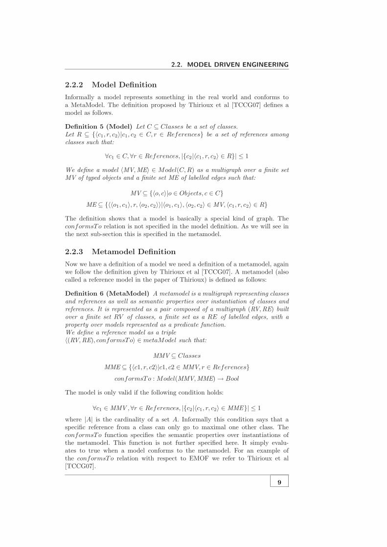
Informally a model represents something in the real world and conforms toa MetaModel. The definition proposed by Thirioux et al [TCCG07] defines amodel as follows.
Definition 5 (Model) Let C ⊆ Classes be a set of classes.Let R ⊆ {〈c1, r, c2〉|c1, c2 ∈ C, r ∈ References} be a set of references amongclasses such that:
∀c1 ∈ C,∀r ∈ References, |{c2|〈c1, r, c2〉 ∈ R}| ≤ 1
We define a model 〈MV,ME〉 ∈ Model(C,R) as a multigraph over a finite setMV of typed objects and a finite set ME of labelled edges such that:
MV ⊆ {〈o, c〉|o ∈ Objects, c ∈ C}
ME ⊆ {〈〈o1, c1〉, r, 〈o2, c2〉〉|〈o1, c1〉, 〈o2, c2〉 ∈ MV, 〈c1, r, c2〉 ∈ R}
The definition shows that a model is basically a special kind of graph. TheconformsTo relation is not specified in the model definition. As we will see inthe next sub-section this is specified in the metamodel.
2.2.3 Metamodel Definition
Now we have a definition of a model we need a definition of a metamodel, againwe follow the definition given by Thirioux et al [TCCG07]. A metamodel (alsocalled a reference model in the paper of Thirioux) is defined as follows:
Definition 6 (MetaModel) A metamodel is a multigraph representing classesand references as well as semantic properties over instantiation of classes andreferences. It is represented as a pair composed of a multigraph (RV,RE) builtover a finite set RV of classes, a finite set as a RE of labelled edges, with aproperty over models represented as a predicate function.We define a reference model as a triple〈(RV,RE), conformsTo〉 ∈ metaModel such that:
MMV ⊆ Classes
MME ⊆ {〈c1, r, c2〉|c1, c2 ∈ MMV, r ∈ References}
conformsTo : Model(MMV,MME)→ Bool
The model is only valid if the following condition holds:
∀c1 ∈ MMV ,∀r ∈ References, |{c2|〈c1, r, c2〉 ∈ MME}| ≤ 1
where |A| is the cardinality of a set A. Informally this condition says that aspecific reference from a class can only go to maximal one other class. TheconformsTo function specifies the semantic properties over instantiations ofthe metamodel. This function is not further specified here. It simply evalu-ates to true when a model conforms to the metamodel. For an example ofthe conformsTo relation with respect to EMOF we refer to Thirioux et al[TCCG07].
9

CHAPTER 2. BASIC CONCEPTS
Again it is important to understand that different MDE approaches use dif-ferent metametamodels and thus allow different metamodels and models. Themetametamodel in the formal framework of Thirioux only contains classes andreferences. Most MDE approaches also allow attributes, class hierarchies andreferences with multiplicities.
2.3 MDE Approaches
MDE and its concepts where introduced by the Object Management Group(OMG) [Sol00]. However, other approaches where proposed as well. This sectionwill discuss the main approaches to MDE and their differences and similarities.First the initial approach of the OMG is covered. Then the approach taken bythe Microsoft Software Factory Tools (MS/DSL) [GSCK04] is discussed. In theend two similar approaches Ecore [ECO], from the Eclipse Modeling Foundation[EMF] , and KM3 [JB06] are covered.
2.3.1 Object Management Group
The Object Management Group (OMG) introduced the Model Driven Architec-ture (MDATM) . They started the development of a metametamodel called theMeta Object Facility (MOF) . This resulted in MOF 1.4 [OMG02] and MOF2.0 [OMG03a]. This language is designed in such a way that it can be used asthe metametamodel for UML [OMG]. However, this comes at a higher com-plexity. The OMG understood that a simpler metametamodel was needed andtherefore defined Essential MOF (EMOF) as a subset of MOF. However, evenEMOF is seen as rather big by the MDE research community. As we will seea simpler metamodel facilitates understanding and makes it a better candidatefor formalization.The semantics of MOF is informally described using text. Ambiguous interpre-tation of MOF can therefore not be prevented and may cause inconsistent toolimplementations. The OMG approach is a rather ambitious approach and triesto cover all aspects of MDE, however, in our view it is better to start with a sim-ple pragmatical MDE approach and extend that if needed instead of enforcinga specific full blown approach.
2.3.2 MS Software Factory Tools
The Microsoft tools for Domain Specific Languages (MS/DSL) is a suite of toolsto support for creating and using domain specific data for automating the soft-ware development process [GSCK04]. MS/DSL takes a pragmatic approach: themain focus is on tool support. The MS/DSL does not have a rigid specification,in fact there is no explicit metametamodel defined [BHJ+05].MS/DSL is a proprietary platform and its main aim is to generate code. Ittherefore comes accompanied with a code generator. However, the aim of MDEis much broader than merely code generation. For example there is no modeltransformation language in MS/DSL. The biggest disadvantage is that it is aclosed platform and it does not have a large research community.An advantage of MS/DSL is that it takes a pragmatical approach to MDE.It comes with a lot of tools that makes the life of the MDE developer easier.
10
2.4. DOMAIN SPECIFIC LANGUAGES
This may be the reason that there is no explicit metamodel defined, this onlymakes the tool complex. This may be appealing for beginners in the MDE field;however, in the long run an explicit defined metamodel is really beneficial.
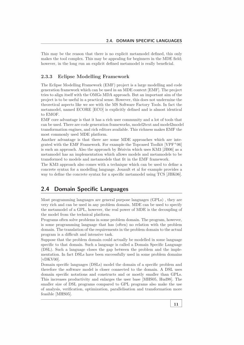
2.3.3 Eclipse Modelling Framework
The Eclipse Modelling Framework (EMF) project is a large modelling and codegeneration framework which can be used in an MDE context [EMF]. The projecttries to align itself with the OMGs MDA approach. But an important aim of theproject is to be useful in a practical sense. However, this does not undermine thetheoretical aspects like we see with the MS Software Factory Tools. In fact themetamodel, named ECORE [ECO] is explicitly defined and is almost identicalto EMOF.
EMF core advantage is that it has a rich user community and a lot of tools thatcan be used. There are code generation frameworks, model2text and model2modeltransformation engines, and rich editors available. This richness makes EMF themost commonly used MDE platform.
Another advantage is that there are some MDE approaches which are inte-grated with the EMF Framework. For example the Topcased Toolkit [VPF+06]is such an approach. Also the approach by Bezivin which uses KM3 [JB06] as ametamodel has an implementation which allows models and metamodels to betransformed to models and metamodels that fit in the EMF framework.
The KM3 approach also comes with a technique which can be used to define aconcrete syntax for a modelling language. Jouault et al for example provides away to define the concrete syntax for a specific metamodel using TCS [JBK06].
2.4 Domain Specific Languages
Most programming languages are general purpose languages (GPLs) , they arevery rich and can be used in any problem domain. MDE can be used to specifythe metamodel of a GPL, however, the real power of MDE is the decoupling ofthe model from the technical platform.
Programs often solve problems in some problem domain. The program, however,is some programming language that has (often) no relation with the problemdomain. The translation of the requirements in the problem domain to the actualprogram is a difficult and intensive task.
Suppose that the problem domain could actually be modelled in some languagespecific to that domain. Such a language is called a Domain Specific Language(DSL). Such a language closes the gap between the problem and the imple-mentation. In fact DSLs have been successfully used in some problem domains[vDKV00].
Domain specific languages (DSLs) model the domain of a specific problem andtherefore the software model is closer connected to the domain. A DSL usesdomain specific notations and constructs and or mostly smaller than GPLs.This increases productivity and enlarges the user base [MHS05, Hud98]. Thesmaller size of DSL programs compared to GPL programs also make the useof analysis, verification, optimization, parallelisation and transformation morefeasible [MHS05].
11

CHAPTER 2. BASIC CONCEPTS
A problem with DSLs is that they are difficult to design and implement andrequire higher initial costs [Hud98]. Here is where MDE comes into play: DSLsand MDE are a perfect match. The MDE approach makes the specification of aDSL much easier. Creating a DSL in the MDE context is often called DomainSpecific Modelling (DSM) [KT08].
2.4.1 MetaModel
The syntax of textual languages is mostly defined using Bachus-Naur Form(BNF). This is also visualized in figure 2.1. The grammar of a language is themetamodel of the language and BNF itself is a metametamodel, in fact BNFcan be described in itself.
When defining a model for a specific domain one uses domain concepts to expressthe model. These domain concepts must be captured in a metamodel for thatdomain. The metamodel for a DSL is analog to the grammar for a textuallanguage. Therefore the structure of a DSL can is captured in a MetaModeland the concrete syntax can be captured using different tools within MDE (forexample TCS [JBK06]).
2.4.2 Semantics
The metamodel for a specific domain only specifies the structure of the models.However, the semantic properties such as conditions over valid models and thebehavioural semantics of a model (if any) are not specified. Semantics are asimportant as the structure of the language. Some argue that semantics are evenmore important than the structure [Hud98].
The semantics of a DSL can be specified in different ways. They can be specificinformally using text or using model-to-code transformations. The semanticscould also be specified in a formal way. More on the general aspects of semanticsof languages can be found in section 2.5.
2.5 Semantics of Languages
Language definition deals with defining the structure of the language. However,the meaning of those structures must also be defined. This meaning is definedby the semantics of the language. The semantics of a language can be definedin different ways. This section explains what the semantics are and we take alook at different approaches for specifying semantics.
2.5.1 General Theory
Any language consists of a structure defined by some syntactic elements. De-pending on the type of the language these elements can be words, sentences,boxes, diagrams etc. However, these structures do not have a meaning with-out semantics. The semantics of a programming language essentially models thecomputational meaning of each program [Mos06]. In order to define the meaninga mapping is defined from the syntax L of the language to a semantic domainS. This mapping M : L→ S defines the meaning of the language [HR04].
12

2.5. SEMANTICS OF LANGUAGES
So in order to define the semantics for a syntax definition on has to choose asemantics domain S and a mapping from the syntax to the semantic domainhas to be made. This mapping defines the meaning of the syntactic elements.The next two subsections will dive into two dimensions of semantics; the for-mality of the semantics and the dimension of static and dynamic semantics.
Formal versus Informal Semantics
Programming language tutorials often explain the meaning the language byexplaining them with text and code examples. Those tutorials explain the se-mantics in an informal manner which is easier for the reader.However, the disadvantages of informal semantics are that they can be ambigu-ous and imprecise. The semantic domain and the mapping from syntax to thedomain are not explicitly specified.Formal semantics on the other hand have an explicit semantic domain, whichis often a well known mathematical domain like natural numbers, graphs orlabelled transition systems. The mapping to that domain is also explicitly given.Formal semantics are precise and computer readable. They can also be combinedwith rigorous mathematical techniques like validation, proofs, simulation etc.
Static and Dynamic Semantics
The semantics of a language can be divided into static and dynamic seman-tics. The static semantics deals with compile-time semantics like type checkingand well-formedness constraints. These semantics are called static because thesesemantics can only be checked before running the program.The dynamic semantics on the other hand models the runtime behaviour ofthe program. All observable behaviour of a running program is defined by thedynamic semantics.
2.5.2 Approaches
There are several approaches to specifying dynamic semantics. Some of theseapproaches are denotational semantics, axiomatic semantics, Abstract State Ma-chine semantics and action semantics [Mos06]. The axiomatic and denotationalapproaches are discussed briefly below. However, the focus of this thesis is onanother approach named structural operational semantics (SOS). This approachis explained in a separate section.
Axiomatic Semantics
Axiomatic semantics [Hoa69] is based on mathematical logic. The semantics of alanguage are specified by making general assertions (or axioms) about syntacticstructures in the language. These assertions are known as Hoare triples writtenas {P}S{Q}. They consist of a precondition P , a syntactic structure S and apostcondition Q. An example assertion is for example:
{x = A}x := x + 1{x = A + 1}
This assertion states that if x equals A, then after execution of the statementx := x+1 the variable x will equal A+1. The semantics of a language is defined
13

CHAPTER 2. BASIC CONCEPTS
by a set of axioms which define the behaviour of all syntactic structures in thelanguage.
Denotational Semantics
Denotational semantics was develop by Scott and Strachey at Oxford [SS71,Sch86]. In denotational semantics the meaning of a language is defined by aset of functions, or denotations. Each denotation of a construct has a set ofarguments that represent the information before its execution and a result thatrepresents the information available after its execution.
Denotational semantics has been used to define the semantics of functional pro-gramming languages. However, attempts to give semantics to larger program-ming languages have been less successful [Mos06].
2.6 Structural Operational Semantics
Structural Operational Semantics (SOS) was first introduced by Plotkin in 1981[Plo81] and has been researched further by other researchers [Hen90], notablyMosses [Mos02, Mos04]. SOS has been used to define the semantics of processalgebras [Mil90] and programming languages [IPW01]. SOS is a compositional:the semantics of a phrase is specified by the semantics of the subphrases. Com-positional rules are used to specify the semantics of a specific language structure.
2.6.1 Semantic Domain
The semantic domain of SOS is a labelled transition system (LTS) (see definition7), which is a well-studied mathematical object.
Definition 7 (Labelled Transition System) A LTS is a triple (Q,A,→)with Q as set of states, a set A of labels α, a relation →⊆ Q × A × Q oflabelled transitions ((s, α, s‘) is written as s
α−→ s‘).
The mapping from the syntactic domain of a language to the semantic domain isdone by defining a SOS specification. A SOS specification consists of a definitionof the states and a set of rules which define the transition relation in the LTS.The states are often sentences of the language with some extensions.
2.6.2 Rules
SOS rules are based on the abstract syntax of a language. A rule consist ofassertion of transitions t
α−→ t′ where the terms t, t′ are syntactic constructs of
the language which contain meta-variables and α is the label of the assertion.A rule is written as follows:
c1, · · · , cn
c(2.1)
Where c, c1, · · · , cn are transition assertions in which c1, · · · , cn are the condi-tions and c is the conclusion of the rule.
14

2.6. STRUCTURAL OPERATIONAL SEMANTICS
2.6.3 Example
In order to understand the rules the abstract syntax and SOS rules for a simpleexpression language will be given. Consider the abstract syntax of a simpleexpression language as defined below:
〈Exp〉 → n | 〈BinaryExp〉〈BinaryExp〉 → 〈Exp〉 〈Exp〉
This is the abstract syntax for a simple language in which the sentences arenumbers n or binary expressions. In order to keep the language simple we didnot add any operators for the binary expressions. In this case a binary expressionis simply an expression which has two sub expressions. A simple sentence of thislanguage is visualised as an abstract syntax tree below:
Exp
BinaryExp
Number
5
Number
3
n
2
This simple language will be used to illustrate how SOS is used to define thesemantics of a language. In order to specify the semantics for this simple lan-guage we must know what the intended behaviour of the language is. In thiscase we simply evaluate a binary expression to the sum of its sub-expressions.Therefore a sentence in this language will always evaluate to a number.The SOS rules that specify this behaviour can be seen below. The rules con-tain meta-variables x, ei and ni. The meta-variable x matches any syntacticconstruct, the meta-variable ei only matches binary expressions and the meta-variable ni only matches numbers.
e1 → e′1BinaryExp (e1, x)→ BinaryExp (e′1, x)
(2.2)
Rule 2.2 consist of a condition e1 → e′1 and a conclusion. The condition can beinterpreted as: there is a rule which transforms the syntactic construct bound toe1 to a new syntactic construct e′1. The conclusion of the rule simply states thatin order to evaluate a binary expression one must first evaluate the first childexpression.
e2 → e′2BinaryExp (n1, e2)→ BinaryExp (n1, e′2)
(2.3)
Rule 2.3 matches binary expressions in which the first child is already evaluatedto a number (which is bound to meta-variable n1). The rule states that if thesecond child, bound to e2, of a binary expression evaluates to e′2 then the binaryexpression will evaluate to a new binary expression in which e2 is substitutedby e′2.
n = n1 + n2
BinaryExp (n1, n2)→ n(2.4)
15

CHAPTER 2. BASIC CONCEPTS
The last rule, rule 2.4, evaluates a binary expression, with two numbers n1 andn2 as children, to the sum of those numbers. The condition n = n1 + n2 is nota transition condition but simply an assertion.Note that the three rules presented here do not strictly follow a specific ruleformat. They are just presented here to give you an intuitive understanding ofSOS. To get a more in depth understanding of SOS it is recommended to readsome papers on SOS, for example the paper by Plotkin [Plo81].
2.6.4 Transition System Specification
The semantic domain of SOS is a LTS. The states of the LTS are extendedsyntactic constructs of the language. The transitions between the states arespecified inductively using the rules. Thus in fact an SOS specification specifiesa LTS and is therefore called a Transition System Specification (TSS) . For aformal definition of TSSs and SOS we refer to papers by Mousavi et al [MRG07].In this introduction we will just explain how a transition in the LTS can beproved by a set of rules. Such a proof is called a proof-tree. We define a prooftree in a similar way as Peter Mosses does in his paper about Modular StructuralOperational Semantics (MSOS) [Mos04].
Definition 8 (Transition Proof Tree) Given a set of rules, a triple (s, α, s‘)is in the transition relation of the LTS if and only if a finite upwardly branch-
ing tree (the proof tree) can be formed that follows satisfies the followingconditions:
1. All nodes are labelled by elements of Q×A×Q
2. the root nodes is labelled by (s, α, s‘)
3. for each node with n child nodes there is a rule c1,··· ,cn
cand an interpre-
tation of the meta-variables such that
• the label of the node is the interpretation of c
• the labels of the child nodes are the interpretations of c1, · · · , cn.
The paper of Plotkin [Plo81] gives some examples of how to create a proof tree.Chapter 3 of this thesis shows how to create a proof tree using the proposedSemantic Language.
2.6.5 SOS Styles
Different authors use SOS in different application domains. However, this re-sulted in a range of SOS styles [MRG07]. In order to choose an appropriate ruleformat for the Semantic Language we must be aware of the current rule stylesand their features.One important distinction in SOS approaches is the small-step approach and thebig-step approach. In the small-step SOS each transition generally correspondsto an indivisible item of information processing. In big-step SOS (also calledNatural Semantics) a computation is a single transition that leads directly toa terminal configuration. For intuitive examples of both big-step and small-steprules we refer to a paper of Mosses [Mos04].
16

2.7. APPROACHES TO DEFINING THE SEMANTICS OF MODELLING
LANGUAGES
In general the small-step style will require a greater number of rules than thesame specification in big-step style. However, the small-step style rules tendto be simpler. Another advantage of the small-step style is that it facilitatesthe description of interleaving. The big-step style can become ambiguous withrespect to interleaving because the big-step style rules do not enforce a specificorder.Other important characteristics of different SOS styles are described in the paperby Mousavi et al [MRG07]. We will not list the SOS formats described in thatpaper (there are more than 17 formats). However, an important conclusion ofthe paper is that negative and infinite conditions are a complicating factor inSOS frameworks.
2.7 Approaches to defining the Semantics of Mod-
elling Languages
2.7.1 Introduction
The problem of defining the semantics of a modelling language is not new.Some considerable amount of research has already been done, this has led to anumber of approaches for defining the semantics. This chapter discusses existingapproaches and gives advantages and disadvantages of the different approaches.This chapter also provides an initial bridge between the MDE and the semanticsof languages in general as explained in the Basic Concepts chapter. It alsoprovides comparison material which is used in the evaluation of this thesis.The sections in this chapter will cover the existing approaches like model trans-formations, graph transformations, Maude, the Topcased Toolkit and semanticanchoring.
2.7.2 Model Transformations
A powerful technique in MDE is model transformations. The unifying conceptin MDE ”Everything is a model” makes the description of model to model trans-formation a relatively easy process. One standard for model transformations isthe QVT (Query/View/Transformation) [OMG08] language as proposed by theObject Management Group (OMG).The model transformation technique is used by Sadelik and Wachsmuth [SW08]to specify the semantics of a modelling language. The approach uses a LTSas the semantic domain. The states (or configurations as called by Sadelik andWachsmuth) are models that conform to the configuration metamodel. The tran-sitions in the LTS are specified by a QVT model-to-model transformation. Aninitialisation transformation is also needed which transforms a model to thefirst initial state model.The authors built an Eclipse plugin, named EProvide, which relies existing tech-nologies like EMF [EMF], MOF [OMG02, OMG03a] and QVT. EProvide usesGraphical Modelling Framework [GMF] to visualize the intermediate states dur-ing simulation.Scheiden and Fischer [SF07] use a similar approach as Sadelik and Wachsmuth.The main difference is in the way the model transformations are defined. Schei-den and Fischer use an action language based on UML activities and OCL
17
CHAPTER 2. BASIC CONCEPTS
[OMG03b] to define the model-to-model transformation. The transformation isdefined graphically which is an advantage according to the authors.
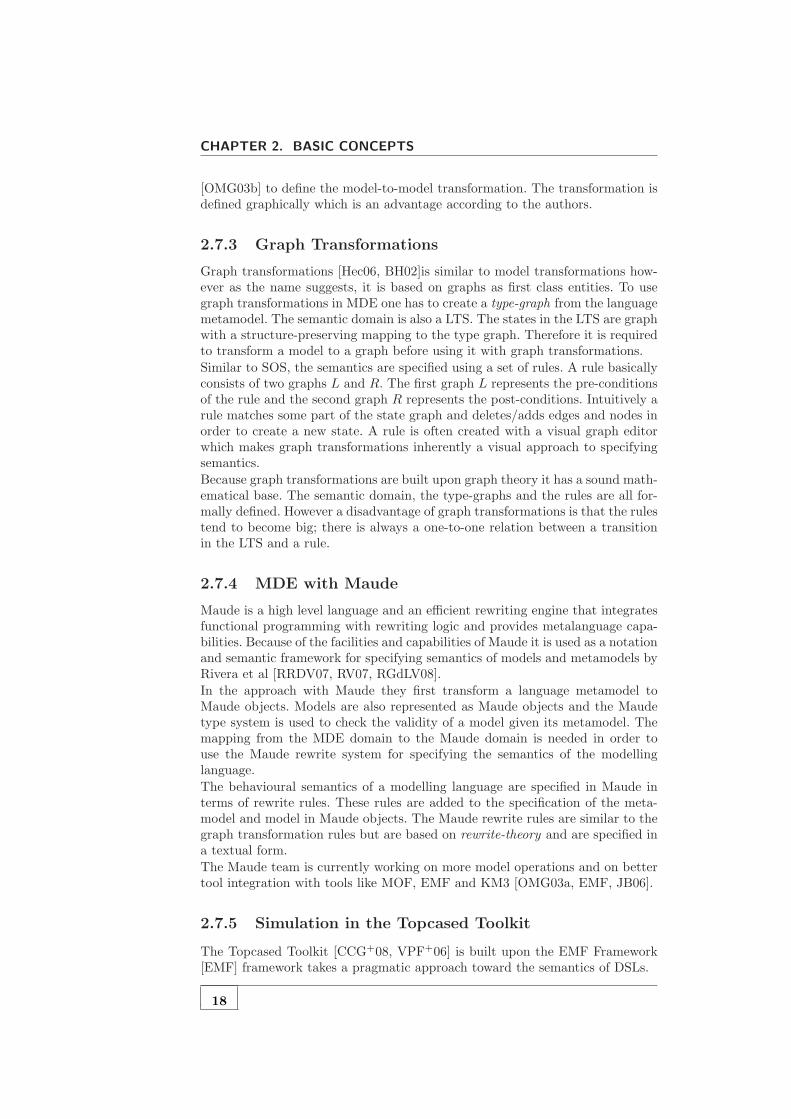
2.7.3 Graph Transformations
Graph transformations [Hec06, BH02]is similar to model transformations how-ever as the name suggests, it is based on graphs as first class entities. To usegraph transformations in MDE one has to create a type-graph from the languagemetamodel. The semantic domain is also a LTS. The states in the LTS are graphwith a structure-preserving mapping to the type graph. Therefore it is requiredto transform a model to a graph before using it with graph transformations.
Similar to SOS, the semantics are specified using a set of rules. A rule basicallyconsists of two graphs L and R. The first graph L represents the pre-conditionsof the rule and the second graph R represents the post-conditions. Intuitively arule matches some part of the state graph and deletes/adds edges and nodes inorder to create a new state. A rule is often created with a visual graph editorwhich makes graph transformations inherently a visual approach to specifyingsemantics.
Because graph transformations are built upon graph theory it has a sound math-ematical base. The semantic domain, the type-graphs and the rules are all for-mally defined. However a disadvantage of graph transformations is that the rulestend to become big; there is always a one-to-one relation between a transitionin the LTS and a rule.
2.7.4 MDE with Maude
Maude is a high level language and an efficient rewriting engine that integratesfunctional programming with rewriting logic and provides metalanguage capa-bilities. Because of the facilities and capabilities of Maude it is used as a notationand semantic framework for specifying semantics of models and metamodels byRivera et al [RRDV07, RV07, RGdLV08].
In the approach with Maude they first transform a language metamodel toMaude objects. Models are also represented as Maude objects and the Maudetype system is used to check the validity of a model given its metamodel. Themapping from the MDE domain to the Maude domain is needed in order touse the Maude rewrite system for specifying the semantics of the modellinglanguage.
The behavioural semantics of a modelling language are specified in Maude interms of rewrite rules. These rules are added to the specification of the meta-model and model in Maude objects. The Maude rewrite rules are similar to thegraph transformation rules but are based on rewrite-theory and are specified ina textual form.
The Maude team is currently working on more model operations and on bettertool integration with tools like MOF, EMF and KM3 [OMG03a, EMF, JB06].
2.7.5 Simulation in the Topcased Toolkit
The Topcased Toolkit [CCG+08, VPF+06] is built upon the EMF Framework[EMF] framework takes a pragmatic approach toward the semantics of DSLs.
18
2.8. CONCLUSION
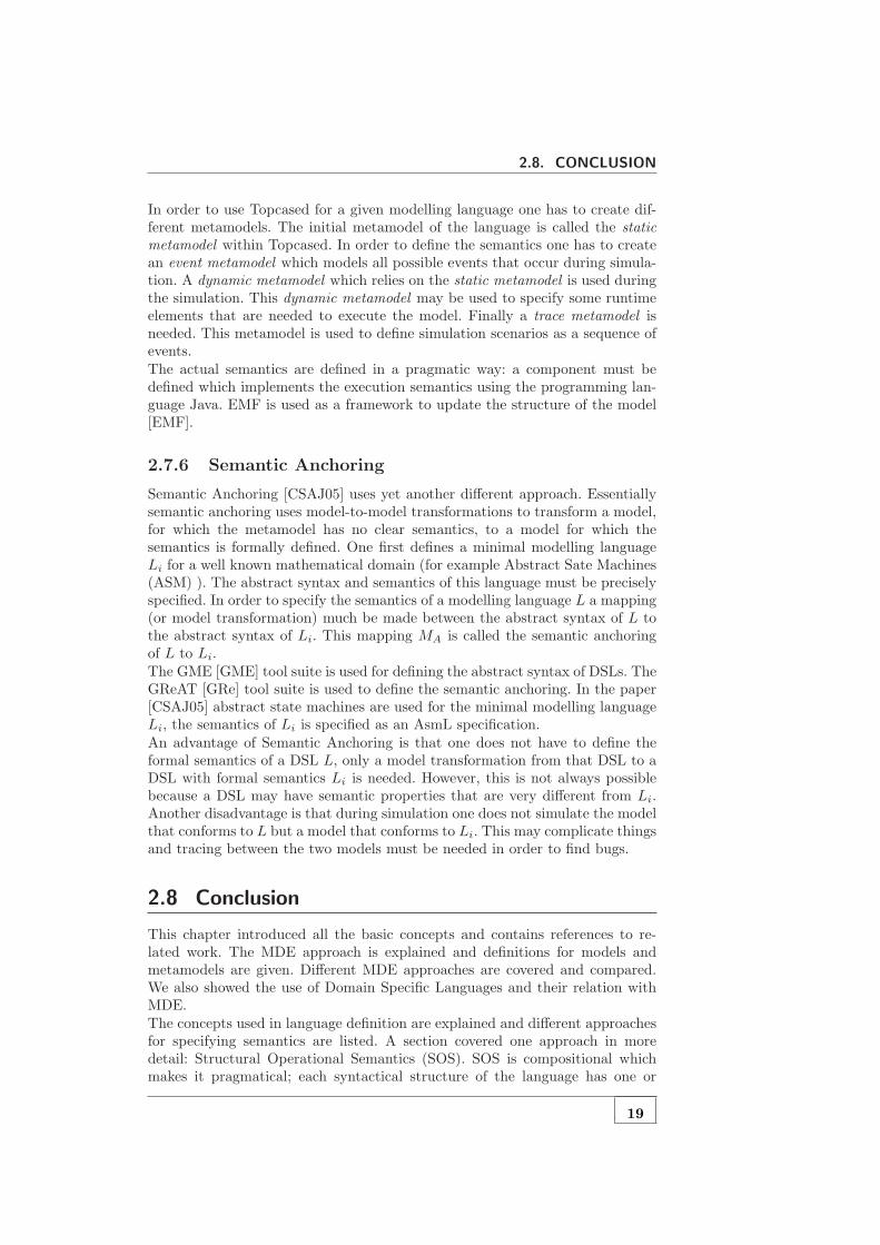
In order to use Topcased for a given modelling language one has to create dif-ferent metamodels. The initial metamodel of the language is called the staticmetamodel within Topcased. In order to define the semantics one has to createan event metamodel which models all possible events that occur during simula-tion. A dynamic metamodel which relies on the static metamodel is used duringthe simulation. This dynamic metamodel may be used to specify some runtimeelements that are needed to execute the model. Finally a trace metamodel isneeded. This metamodel is used to define simulation scenarios as a sequence ofevents.The actual semantics are defined in a pragmatic way: a component must bedefined which implements the execution semantics using the programming lan-guage Java. EMF is used as a framework to update the structure of the model[EMF].
2.7.6 Semantic Anchoring
Semantic Anchoring [CSAJ05] uses yet another different approach. Essentiallysemantic anchoring uses model-to-model transformations to transform a model,for which the metamodel has no clear semantics, to a model for which thesemantics is formally defined. One first defines a minimal modelling languageLi for a well known mathematical domain (for example Abstract Sate Machines(ASM) ). The abstract syntax and semantics of this language must be preciselyspecified. In order to specify the semantics of a modelling language L a mapping(or model transformation) much be made between the abstract syntax of L tothe abstract syntax of Li. This mapping MA is called the semantic anchoringof L to Li.The GME [GME] tool suite is used for defining the abstract syntax of DSLs. TheGReAT [GRe] tool suite is used to define the semantic anchoring. In the paper[CSAJ05] abstract state machines are used for the minimal modelling languageLi, the semantics of Li is specified as an AsmL specification.An advantage of Semantic Anchoring is that one does not have to define theformal semantics of a DSL L, only a model transformation from that DSL to aDSL with formal semantics Li is needed. However, this is not always possiblebecause a DSL may have semantic properties that are very different from Li.Another disadvantage is that during simulation one does not simulate the modelthat conforms to L but a model that conforms to Li. This may complicate thingsand tracing between the two models must be needed in order to find bugs.
2.8 Conclusion
This chapter introduced all the basic concepts and contains references to re-lated work. The MDE approach is explained and definitions for models andmetamodels are given. Different MDE approaches are covered and compared.We also showed the use of Domain Specific Languages and their relation withMDE.The concepts used in language definition are explained and different approachesfor specifying semantics are listed. A section covered one approach in moredetail: Structural Operational Semantics (SOS). SOS is compositional whichmakes it pragmatical; each syntactical structure of the language has one or
19
CHAPTER 2. BASIC CONCEPTS
more rules, the rules in the small-step approach are generally small and therules only refer to directly accessible elements.This chapter also covered different approaches for defining the semantics ofmodelling languages. In all approaches there is a mapping from the modellinglanguage to a semantic domain. However, this mapping is done in different ways.Most approaches specialized LTS as the semantic domain, however the transitionrelation in the LTS is specified in different manners.The approaches differ in some aspects. Some approaches are have a rigorousformal basis however other approaches use a more pragmatical approach. Noneof the existing approaches use SOS as a framework for specifying semantics. Thenext chapter will explain how SOS can be used in an MDE context.
20

3An SOS based Semantic Language DSL
3.1 Introduction
Semantics of models can be expressed in different ways. This chapter takes aMDE approach to specifying dynamic semantics. We will create a DSL, namedSemLang (an abbreviation for Semantic Language), which can be used to de-scribe the semantic of other DSLs. SemLang will be built upon existing knowl-edge about SOS and MSOS.
This chapter explains SemLang informally with the aid of examples. A formaldefinition will be given in chapter 4. The examples start with a definition of aDSL, sequentially the semantics of the DSL is defined using SemLang. Eachsection adds more complexity to SemLang. After this chapter the reader shouldhave a complete but informal understanding of SemLang and the differencesbetween the well known SOS (Plotkin style) and SemLang.
In this chapter we will use the term DSL for the language for which the semanticsis described. The difference between the SemLang and the DSL for which thesemantics is described is crucial. This is visualized in figure 3.1.
Figure 3.1: SemLang describes the semantics of a DSL
It is important that the semantics of our SemLang is also expressed formally,this prevents ambiguity and provides consistency, completeness and correct-
21

CHAPTER 3. AN SOS BASED SEMANTIC LANGUAGE DSL
ness. This chapter, however, does not deal with formalization and is meant tobe relatively easy reading. This is done to facilitate the understanding of theformalization in the next chapter.Note that the metamodels and models defined in this chapter are built using theEclipse Modelling Framework [EMF]. EMF is chosen because it has explicitlydefined metametamodels and the tool support is well developed. For furtherreasons see section 2.3.3. Therefore the metamodels in this chapter conform tothe ECORE metametamodel [ECO]. Because SemLang is a DSL itself it mustalso have a metamodel. The metamodel is too big to include here, but it isincluded in appendix A on the disc.
3.2 SOS for Expressions
In this section we will define a simple expression language by giving its meta-model. A small sample model is also given. The semantics is explained bothinformally as well as formally using SemLang. In the end of this section thesample model will be simulated by applying the semantics.
3.2.1 Metamodel
First the semantics of a simple expression language will be defined. The expres-sion language only consists of the concepts Expression, Number and Binary-Expression. The metamodel is given in figure 3.2. Models of the metamodelsare either numbers or expressions. Also note that the models are always trees,this is because the lhs and rhs relations of a binary expression are containmentrelations (as specified by metametamodel ECORE [ECO]).
Figure 3.2: Expression language metamodel
An example model that conforms to the expression language metamodel is givenin figure 3.3. The meaning of the nodes is explained in the list below:
• Black nodes represent objects, the label of the node is the name of theclass that it conforms to.
– The outgoing edges of an object node are either references or at-tributes
– Black outgoing edges are containment references
– Green outgoing edges are attributes
– The name of an edges refers to the name of the reference or attribute
22

3.2. SOS FOR EXPRESSIONS
• Green nodes represent attribute values
Figure 3.3: Expression language sample model
The example model is needed to show how the semantics is applied to a spe-cific model. Before the model can be executed the semantics of the expressionlanguage must be defined.
3.2.2 Semantics
The semantics of the expression language is very simple: a binary expressionevaluates to the sum of its operands. The result of a full computation is thereforethe sum of all the numbers in the model. This description is of course incompleteand informal.The semantics must be described formally using a flavour of SOS suited forDSLs. As explained in section 2.6 an SOS specification consists of a number ofrules. These rules specify the transition relation between states when executinga model. A transition is only valid if a tree of rules can be constructed whichexplain the transition (for full details see [Mos04]).Because of the simplicity of the expression language we can create SOS rules withminimal modification to the format of the rules. Plotkin style SOS [Plo81] usesthe syntax of the language in the rules. As explained in section 2.2.1 a metamodelplays the same role in a DSL as the syntax does in a textual language. Thereforewe change the format of the rules in such a way that we refer to the metamodelinstead of the syntax. The rules for the expression language are given below.The first equation is not a rule, it declares which states are end states (computedstates). This is needed for every SOS specification to indicate when an end stateis reached. The end state specification is rather simple: it declares that objectsthat conform to the Number class are end states.The three rules themselves consist of conditions, a pattern and a result as ex-plained in section 2.6. The pattern consists of a name of a class. Only objectsthat conform to that class are matched. The pattern also consists of zero or morevariable bindings. These variables are bound to either attribute values or refer-enced objects. All the rules have a pattern like BinaryExp (lhs = L, rhs = R)
23

CHAPTER 3. AN SOS BASED SEMANTIC LANGUAGE DSL
Computes = {Number} (3.1)
L→ NL
BinaryExp (lhs = L, rhs = R)→ BinaryExp (lhs = NL, rhs = R)(3.2)
R→ NR
BinaryExp (lhs = L, rhs = R)→ BinaryExp (lhs = L, rhs = NR)(3.3)
BinaryExp (lhs = L, rhs = R)→ Number (val = (L.val + R.val)) (3.4)
Figure 3.4: Semantic SOS rules for the expression language
which matches objects that conform to the BinaryExp class, the variables Land R are bound to the value of lhs and rhs respectively.
There is one subtle difference between the patterns in the rules; the variable Lis italic in the second rule, and both L and R are italic in the last rule. Italicvariables are called computed variables. Computed variables can only bind toa computed value, as defined by the equation Computes = {Number}. If acomputed variable cannot be bound then the rule does not match. This is also asubtle difference with respect to the Plotkin rule format. Plotkin uses differentsymbols for computed values (for example m and n for numbers). Note that nonitalic variables can also match computed values: italic variables match a subsetof what non-italic variables match.
Rule 3.2 and 3.3 come with conditions like L → NL. The variable at the leftside of the arrow (L) in the condition must be bound to an object in the patternof the rule. The condition holds if there is a rule x that matches the object towhich L is bound to. If there is a rule found then NL is bound to the result ofthe application of rule x. If such a rule cannot be found then the condition doesnot hold. If a condition does not hold then the rule itself does not match. Thevariable at the right side of the arrow (NL) can be used in the result of the rule.
The result of a rule looks similar to the pattern. However, it is more complexand has a different purpose: it constructs new objects. For example the rule 3.2has the result BinaryExp (lhs = NL, rhs = R). This constructs a new objectthat conforms to the Expression class and sets lhs to a copy of the object towhich the variable NL is bound to. The rhs reference is bound to the copy ofthe object to which the variable L is bound to.
The copy algorithm can be kept simple in this case. This is because the meta-model of the expression language does not have cross-references; the model willalways be a tree. Therefore the copy algorithm only has to deal with trees. Thecopy algorithm simply copies the current object and its complete tree. The lastDSL for which we describe the semantics (in section 3.5) does contain crossreferences. The complete copy algorithm is explained there.
The result in rule 3.4 Number (val = (L.val + R.val)) constructs a Numberobject. The attribute val is assigned the sum of the val attribute of R and L.This shows how the result of a rule can contain simple mathematical expressions.
24

3.2. SOS FOR EXPRESSIONS
Plotkin could not embed these expressions directly in the rules because theycould interfere with the syntax of the language for which the semantics weredescribed. Because the SemLang rule format does not refer to the syntax of theDSL we can simply embed these calculations in the rules.
3.2.3 Example Simulation
The semantics of the expression language is specified: the end state is defined andthe rules are given and their format is explained (informally). The sample modelin figure 3.3 can now be executed. The semantics of the expression language ismodelled by a transition system. A transition system consists of states andtransitions. Execution in the sense of SOS is a path in a transition system. Thepath consists of states and transitions from state to state. The last state is avalid end state. Each transition is proved by a tree of rules.
ExecutionPath = State1 → State2 → · · · → Staten−1 → Staten = EndState
The transitions can be labelled, but for now they will not be labelled. Thetransitions are specified by the rules. However, we must clearly define the statesof the transition system. The result part of every rule creates a new object thatconforms to the metamodel. There are no elements created that are not definedby the metamodel. Therefore in this stage the states can be defined as modelsthat conform to the metamodel of the DSL (the expression language).
When executing the sample model the first state is identical to the sample modelitself. This state is not an end state because the root object does not conformto a Number. Therefore all rules that match will be applied to create the newstate. Only rule 3.3 matches.
Rule 3.2 does not match because the transition condition L→ NL does not hold:the L was bound to value of the lhs, which is a Number object. The transitioncondition did not hold because there was no rule found which matches the LNumber object.
Rule 3.3 does match because the computed variable L was successfully boundto the lhs object. Variable R was bound to the rhs object, which conforms to aBinaryExp. The transition condition R → NR holds because a rule could befound which matches the R object: This is rule 3.2.
At this stage the variable L will be bound the lhs which is a BinaryExp. Thevariable R is bound to the rhs which is a Number (where attribute val equals2). Note that rule 3.3 does not match because the lhs was not a computed value.The transition condition L → NL of also holds because the last rule 3.4 whichtransforms a binary expression to a number can be applied.
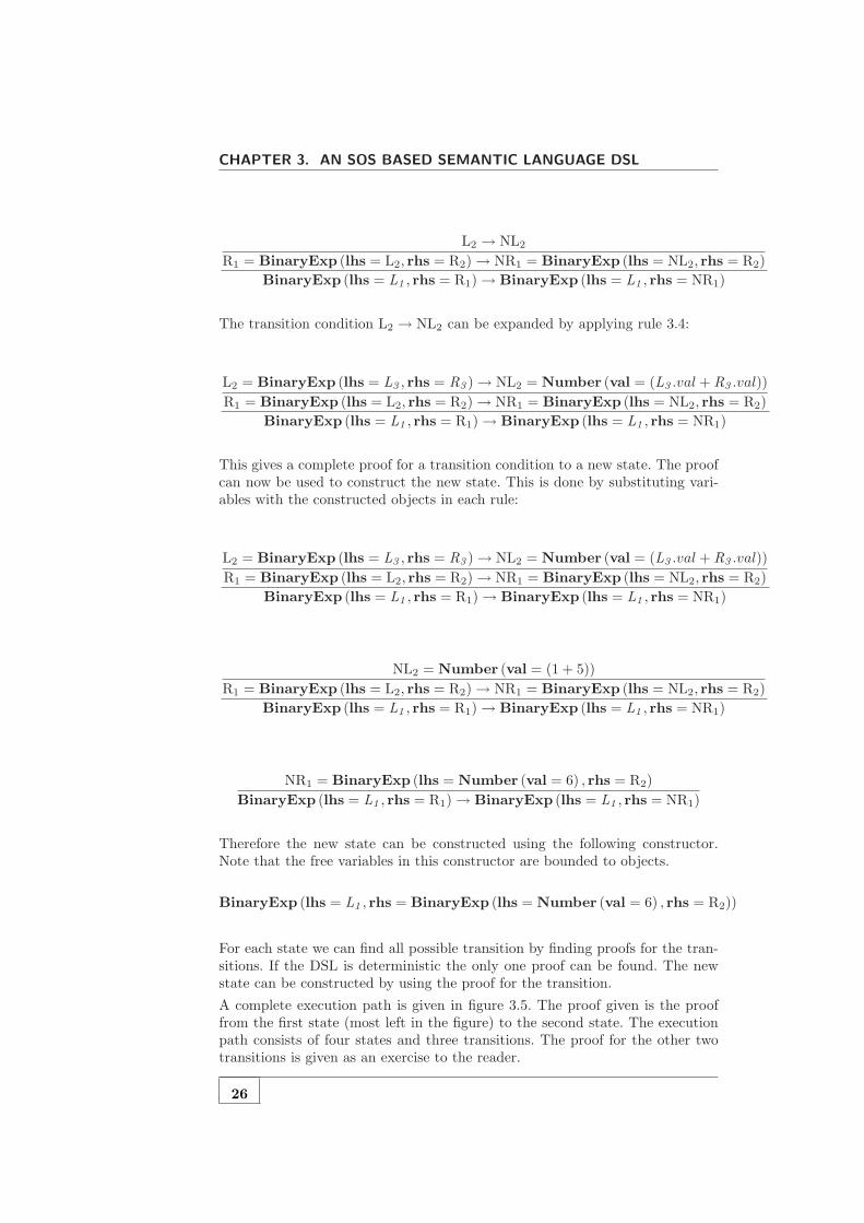
The complete proof for the transition can be given by expanding the transitionconditions. The first rule that is matched is rule 3.3:
R1 → NR1
BinaryExp (lhs = L1 , rhs = R1)→ BinaryExp (lhs = L1 , rhs = NR1)
The transition condition R1 → NR1 can be expanded by applying rule 3.3:
25
CHAPTER 3. AN SOS BASED SEMANTIC LANGUAGE DSL
L2 → NL2
R1 = BinaryExp (lhs = L2, rhs = R2)→ NR1 = BinaryExp (lhs = NL2, rhs = R2)
BinaryExp (lhs = L1 , rhs = R1)→ BinaryExp (lhs = L1 , rhs = NR1)
The transition condition L2 → NL2 can be expanded by applying rule 3.4:
L2 = BinaryExp (lhs = L3 , rhs = R3 )→ NL2 = Number (val = (L3 .val + R3 .val))
R1 = BinaryExp (lhs = L2, rhs = R2)→ NR1 = BinaryExp (lhs = NL2, rhs = R2)
BinaryExp (lhs = L1 , rhs = R1)→ BinaryExp (lhs = L1 , rhs = NR1)
This gives a complete proof for a transition condition to a new state. The proofcan now be used to construct the new state. This is done by substituting vari-ables with the constructed objects in each rule:
L2 = BinaryExp (lhs = L3 , rhs = R3 )→ NL2 = Number (val = (L3 .val + R3 .val))
R1 = BinaryExp (lhs = L2, rhs = R2)→ NR1 = BinaryExp (lhs = NL2, rhs = R2)
BinaryExp (lhs = L1 , rhs = R1)→ BinaryExp (lhs = L1 , rhs = NR1)
NL2 = Number (val = (1 + 5))
R1 = BinaryExp (lhs = L2, rhs = R2)→ NR1 = BinaryExp (lhs = NL2, rhs = R2)
BinaryExp (lhs = L1 , rhs = R1)→ BinaryExp (lhs = L1 , rhs = NR1)
NR1 = BinaryExp (lhs = Number (val = 6) , rhs = R2)
BinaryExp (lhs = L1 , rhs = R1)→ BinaryExp (lhs = L1 , rhs = NR1)
Therefore the new state can be constructed using the following constructor.Note that the free variables in this constructor are bounded to objects.
BinaryExp (lhs = L1 , rhs = BinaryExp (lhs = Number (val = 6) , rhs = R2))
For each state we can find all possible transition by finding proofs for the tran-sitions. If the DSL is deterministic the only one proof can be found. The newstate can be constructed by using the proof for the transition.
A complete execution path is given in figure 3.5. The proof given is the prooffrom the first state (most left in the figure) to the second state. The executionpath consists of four states and three transitions. The proof for the other twotransitions is given as an exercise to the reader.
26

3.3. INTRODUCING THE STORE
BinaryExp
Number
lhs
BinaryExp
rhs
BinaryExp
Integer:1
Number
val
Integer:2
Number
val
Integer:7
val
Number
Integer:5
val
BinaryExp
lhs rhs
rhs lhs
Number
lhs
BinaryExp
rhs
BinaryExp
Integer:6
Number
val
Integer:7
val
Integer:2
Number
val
lhs rhs
Number
rhs
Number
lhs
Number
Integer:8
val
Integer:7
val
Integer:15
val
Figure 3.5: Execution states after applying the rules to the example model
3.3 Introducing the Store
This section introduces a simple imperative language. First the language will beexplained by defining the metamodel and giving a small sample model. Then thesemantics will be defined using SemLang. This requires that SemLang mustbe extended to deal with a store. In the end the semantics will be applied tothe sample model.
3.3.1 MetaModel
The imperative language consists of binary expressions as explained in the previ-ous section. However, a binary expression also has an operator. In this languagewe only have a Plus and a Minus operator.
The simple imperative language given in this section also allows occurrencesof variables; a value can be assigned to them and their value can be retrieved.Therefore a new expression is added: the Var expression. Var evaluates to thevalue of the variable that it is referring to.
The main difference is that the imperative language given here allows commandsto be executed sequentially. A command is either a Seq command or an Assigncommand. A complete metamodel is given in figure 3.6. The given language isalmost identical to the language given by Plotkin in chapter two of his paper[Plo81]. The main difference is again that our language is a DSL defined as ametamodel.
Notice we do not use collections (reference multiplicities greater than one) in ourmetamodel. This is done to keep the metamodel close to the language as definedby Plotkin. The rules must allow list-matching and list-construction when usinglists in the metamodel. This is introduced in the last section in this chapter.
27

CHAPTER 3. AN SOS BASED SEMANTIC LANGUAGE DSL
Figure 3.6: Simple imperative language metamodel
Representing an example model of this language as a graph tends to becomelarge. Therefore the example model will be given in textual form to accommo-date easier understanding. However, this requires that we give a syntax definitionfor the metamodel. This is done by using the Textual Concrete Syntax (TCS)technology as defined by Jouault, Bezivin and Kurtev [JBK06].
Listing 3.1: TCS for the simple imperative DSL� �
1 template Exp main abstract ;2 template Number : va l ;3 template Var : name ;4 template BinaryOp abstract ;5 template Plus : ”+” ;6 template Minus : ”−” ;7 template BinaryExp : ” (” l h s bop rhs ” )” ;8 template Com main abstract ;9 template Assign : name ”:=” e ;
10 template Seq : ” (” c0 ” ; ” c1 ” )” ;� �
This TCS specification can be used to represent a model in textual form. Anexample model is given below.
Listing 3.2: Textual sample model� �
1 ( a :=10;2 ( b:=(10+a ) ;3 a :=(b−3)4 )5 )
� �
To be complete this model is also given as a graph in figure 3.7. This model isretrieved by parsing the sample code using the TCS syntax definition. For fulldetails we refer to the TCS paper [JBK06].
28

3.3. INTRODUCING THE STORE
Seq
Seq
c1
Assign
c0
Integer:10
Var
b
name
BinaryExp
Number
lhs
Var
rhs
Plus
bop
Assign
e
b
name
BinaryExp
lhs
Number
rhs
Minus
bop
Integer:3
val
Assign
e
a
name
Number
val
Integer:10
val
a
name
c0 c1
a
e name
Figure 3.7: Sample model as a graph
3.3.2 Semantics
The semantics of the simple imperative language is first explained informally.Expressions are evaluated analogous to the semantics of the expression language(as explained in the previous section). The only difference is that the calculationthat must be performed is specified by the operator, either Min for subtractionor Plus for addition. The Var expression is evaluated by getting the value ofthe referring variable from the store (internal memory).
A Seq is executed by first executing c0 and then executing c1. An Assignmentis executed by first executing the expression and then by updating the store bybinding the calculated value to the name of the variable. Executing a commanddoes not yield a result.
The informal description of the imperative language includes the need of memoryin which variables can be created, read, updated (and deleted). Therefore weadd the concept of store, which is an abstraction of memory, to our SemLangjust like Plotkin did in chapter 2 of his paper [Plo81]. In the approach of Plotkina store is a function from names to values. To keep our approach flexible wedefine a store as a function from (ECORE) objects to other objects: Store :Object→ Object.
Each object has its own identity. When an object gets created it is assignedan identity. If it is copied then the copy gets a new identity. An object equalsanother object if it has the same identity. However, primitive objects like stringsand integers have a different identity; they have the same identity if their valuesare equal.
Plotkin added the store to the states of the transition system that is specified bya set of rules. A more modular approach MSOS (Modular SOS) was introducedby Mosses [Mos99, Mos02, Mos04]. In MSOS the store operations are specifiedin the labels. SemLang will adopt MSOS: the operations will be specified in
29

CHAPTER 3. AN SOS BASED SEMANTIC LANGUAGE DSL
the labels. However, internally the store will be added to a state. This is morereadable and avoids using the use of category theory that MSOS requires.
The SemLang rules for the imperative language are explained step by step.First some simple rules are explained and then more complex rules that dealwith the store are explained. The new constructs that are added to SemLangwill also be explained.
The rules for BinaryExp are almost identical to the rules for the expressionlanguage. These are presented in figure 3.8. An additional construct in the rulesis a type-check condition. For example the condition O ∈ Plus holds if theobject bounded to O conforms to the Plus class in the metamodel.
Computes = {Nil,Number}
L→ NL
BinExp (lhs = L,bop = O, rhs = R)→ BinExp (lhs = NL,bop = O, rhs = R)(3.5)
R→ NR
BinExp (lhs = L,bop = O, rhs = R)→ BinExp (lhs = L,bop = O, rhs = NR)(3.6)
O ∈ Plus
BinExp (lhs = L,bop = O, rhs = R)→ Number (val = (L.val + R.val))(3.7)
O ∈Minus
BinExp (lhs = L,bop = O, rhs = R)→ Number (val = (L.val − R.val))(3.8)
Figure 3.8: SOS rules for binary expressions
Notice that the set of computed values {Nil,Number} includes Nil. Nil refersto a pseudo-object that represents no value, or no object. Computes = {Nil,Number}defines therefore that the Nil pseudo-object or a Number object is a valid endstate.
The introduction of Nil means that the states are not pure models that conformto the DSL metamodel. A state now must conform to a different metamodel thatis an extension of the DSL metamodel. The only extension is that any referencemay also point to a Nil object.
Next the rules that deal with the Var expression and the commands (Seq andAssign) are introduced. Two rules deal with the evaluation of a Seq command.Rule 3.9 makes sure that first the object assigned to c0 is evaluated. Rule 3.10states that a Seq command evaluates to the object assigned to c1 if the objectassigned to c0 is a computed value. Together they define the order in whichcommands are executed.
30
3.3. INTRODUCING THE STORE
C0→ NC
Seq (c0 = C0, c1 = C1)→ Seq (c0 = NC, c1 = C1)(3.9)
Seq (c0 = C0 , c1 = C1)→ C1 (3.10)
Figure 3.9: Rules for the Seq command
In order to evaluate both a Var and an Assignment we need a store. The storewill represented using a function:
Store : Object→ Object
A function consists of zero or more tuples, a tuple with a key k and a value vis written as k 7→ v. A concrete function with n tuples can be written as:
{k1 7→ v1, k2 7→ v2, . . . , kn−1 7→ vn−1, kn 7→ vn}
There are some operations that can be performed on a function. Suppose wehave a function named a, then a(k) result in the value that is bound to k, orNil if the key is not found. More formally:
Suppose we have another function named b, then the expression a [b] results ina new function with tuples a ∪ b, however if there is a key clash then the tupleof b is used. This operation is called overriding. More formally if c = a [b] then
SemLang is extended by allowing the definition of functions (which can be usedas a store). Each function has a name, domain and range. A function is definedby as follows:
functionName : DomainClass→ RangeClass
where functionName indicates the name of the function. DomainClass andRangeClass both refer to class names in the DSL metamodel. Only objectsthat conform the DomainClass can be used as keys, objects that conform tothe RangeClass can be used as values.
The DSL only needs a function that maps variables to number, therefore equa-tion 3.11 defines a function named store that maps variable names to numbers.The function definition and the final rules are presented in figure 3.10.
Note that most programming languages do not bind variables to values directly.The notion of location is used to decouple the variables from the values. Alocation can be seen as a memory address. A variable binds to a location, and alocation binds to a value. This can be achieved by defining two functions. Firsta function that binds variables to locations: store : String → Integer. And afunction that maps locations to values: memory : Integer→ Number.
Rule 3.12 evaluates a Var expression with the name bound to N to the valuestore (N). This is value v if N 7→ v ∈ store. Informally: a Var evaluates to itscurrent value in the store function.
Two rules deal with the evaluation of an assignment. Rule 3.13 makes sure thatthe expression bound to e is first evaluated to a computed value. Rule 3.14 ismore complicated. It evaluates to Nil but it updates the store function.
31

CHAPTER 3. AN SOS BASED SEMANTIC LANGUAGE DSL
store : String→ Number (3.11)
Var (name = N)→ store (N) (3.12)
E→ NE
Assign (name = N, e = E)→ Assign (name = N, e = NE)(3.13)
Assign (name = N, e = E )store′=store[{N7→E}]−−−−−−−−−−−−−−→ Nil (3.14)
Figure 3.10: Store definition and rules for Assign and Var
Rule 3.14 introduces some new notation. The new notation is a label on thearrow. The label in rule 3.14 is:
store′ = store [{N 7→ E}] (3.15)
A label is used to update a function. The format of the label is:
functionName′ = functionExpression
It means that the function named functionName is set to the value of function-Expression in the next state. A functionExpression is an expression that resultsin a new function. This expression can be a new function by using the format{k1 7→ v1, . . . , kn 7→ vn}. The expression can also be a reference to a function(by using its name). Another possibility is the usage of the override expression.
Label 3.15 updates the function named store to the expression store [{N 7→ E}]in the next state. The expression indicates that the current value of store must beoverridden with {N 7→ E}. This value is a new function with one tuple N 7→ E .Both variables N and E were bound to an object in the pattern part of therule: Assign (name = N, e = E ). The total result of the expression is a newfunction where N 7→ E is added to the existing store function (if a tuple withkey N already existed it is overridden). This new function is then bounded tothe function named store in the new state.
3.3.3 Example Simulation
In this section the simulation of the sample model will be explained. Most rulesthat describe the semantics of the simple imperative language do not introducenew concepts compared to the rules in the simple expression language. Thereforethe explanation of the simulation will be limited to the new constructs that usefunctions.
Some aspects of the first transition, from the first state to the second state, willbe highlighted. This is done in order to explain the effects of having a functionduring simulation. The first transition is visualised in figure 3.11.
32
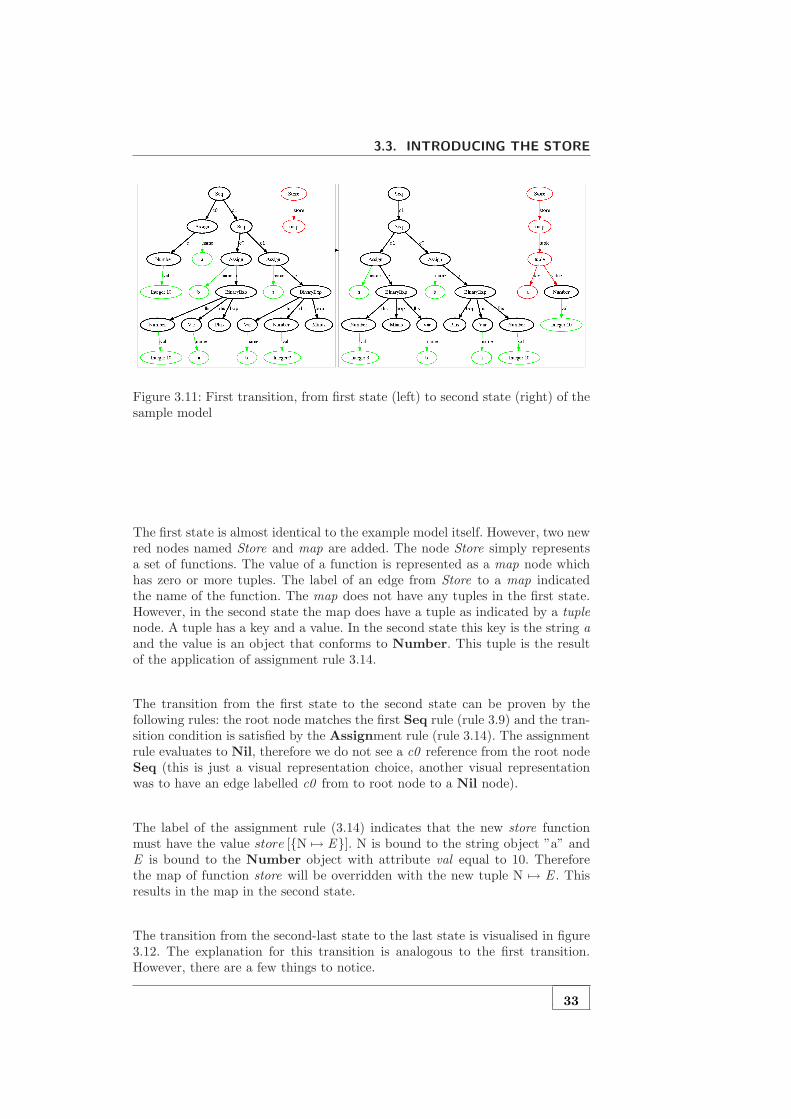
3.3. INTRODUCING THE STORE
Figure 3.11: First transition, from first state (left) to second state (right) of thesample model
The first state is almost identical to the example model itself. However, two newred nodes named Store and map are added. The node Store simply representsa set of functions. The value of a function is represented as a map node whichhas zero or more tuples. The label of an edge from Store to a map indicatedthe name of the function. The map does not have any tuples in the first state.However, in the second state the map does have a tuple as indicated by a tuplenode. A tuple has a key and a value. In the second state this key is the string aand the value is an object that conforms to Number. This tuple is the resultof the application of assignment rule 3.14.
The transition from the first state to the second state can be proven by thefollowing rules: the root node matches the first Seq rule (rule 3.9) and the tran-sition condition is satisfied by the Assignment rule (rule 3.14). The assignmentrule evaluates to Nil, therefore we do not see a c0 reference from the root nodeSeq (this is just a visual representation choice, another visual representationwas to have an edge labelled c0 from to root node to a Nil node).
The label of the assignment rule (3.14) indicates that the new store functionmust have the value store [{N 7→ E}]. N is bound to the string object ”a” andE is bound to the Number object with attribute val equal to 10. Thereforethe map of function store will be overridden with the new tuple N 7→ E . Thisresults in the map in the second state.
The transition from the second-last state to the last state is visualised in figure3.12. The explanation for this transition is analogous to the first transition.However, there are a few things to notice.
33
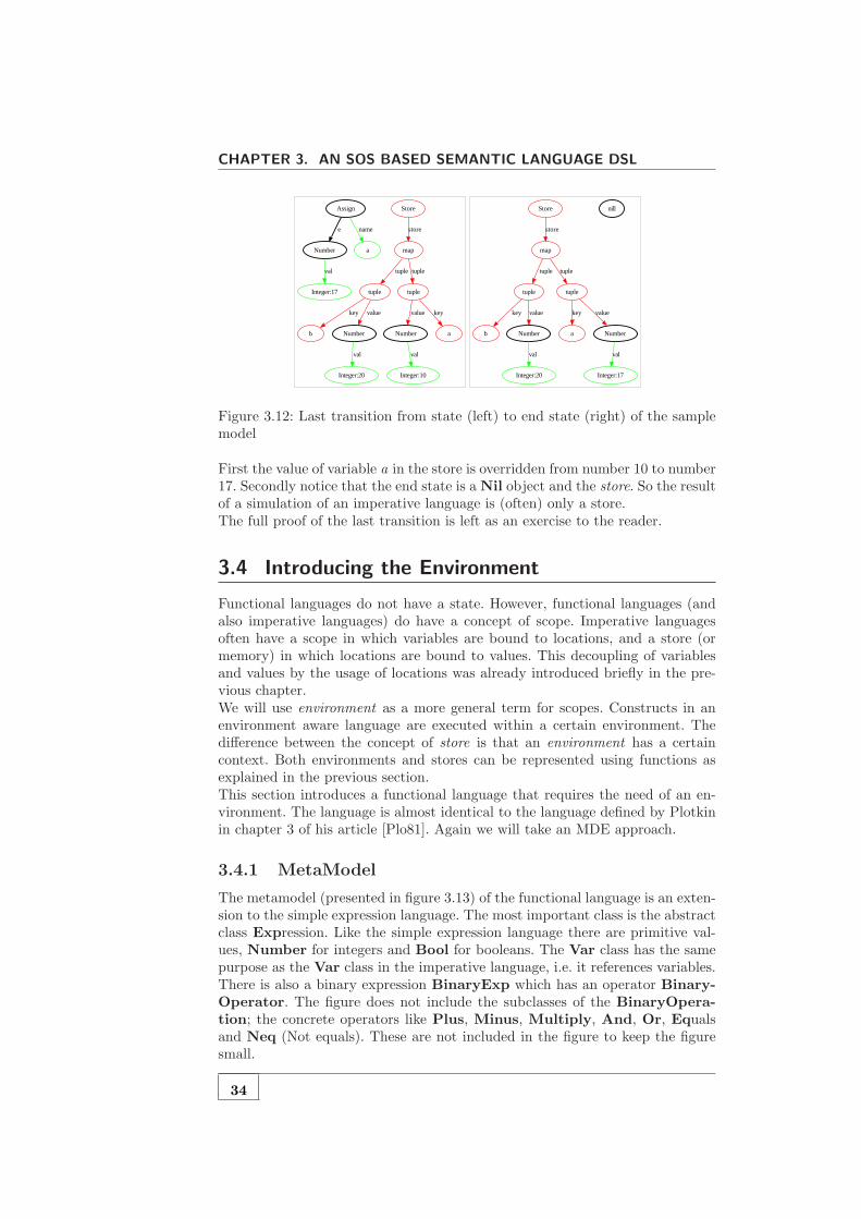
CHAPTER 3. AN SOS BASED SEMANTIC LANGUAGE DSL
tuple
b
key
Number
value
Number
Integer:10
val
tuple
value
a
key
Store
map
store
Integer:20
Number
Integer:17
val tuple tuple
val
a
Assign
e name
nill
Integer:20
tuple
b
key
Number
value
tuple
a
key
Number
value
val
Store
map
store
Integer:17
val
tuple tuple
Figure 3.12: Last transition from state (left) to end state (right) of the samplemodel
First the value of variable a in the store is overridden from number 10 to number17. Secondly notice that the end state is a Nil object and the store. So the resultof a simulation of an imperative language is (often) only a store.The full proof of the last transition is left as an exercise to the reader.
3.4 Introducing the Environment
Functional languages do not have a state. However, functional languages (andalso imperative languages) do have a concept of scope. Imperative languagesoften have a scope in which variables are bound to locations, and a store (ormemory) in which locations are bound to values. This decoupling of variablesand values by the usage of locations was already introduced briefly in the pre-vious chapter.We will use environment as a more general term for scopes. Constructs in anenvironment aware language are executed within a certain environment. Thedifference between the concept of store is that an environment has a certaincontext. Both environments and stores can be represented using functions asexplained in the previous section.This section introduces a functional language that requires the need of an en-vironment. The language is almost identical to the language defined by Plotkinin chapter 3 of his article [Plo81]. Again we will take an MDE approach.
3.4.1 MetaModel
The metamodel (presented in figure 3.13) of the functional language is an exten-sion to the simple expression language. The most important class is the abstractclass Expression. Like the simple expression language there are primitive val-ues, Number for integers and Bool for booleans. The Var class has the samepurpose as the Var class in the imperative language, i.e. it references variables.There is also a binary expression BinaryExp which has an operator Binary-Operator. The figure does not include the subclasses of the BinaryOpera-tion; the concrete operators like Plus, Minus, Multiply, And, Or, Equalsand Neq (Not equals). These are not included in the figure to keep the figuresmall.
34
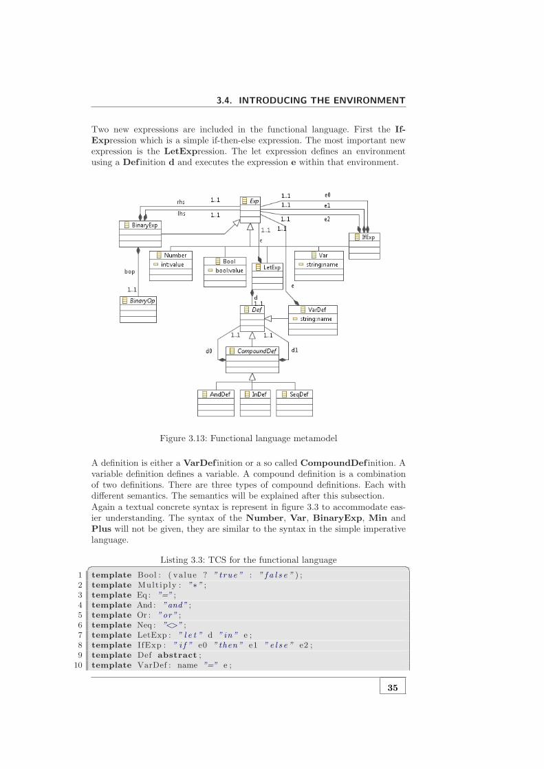
3.4. INTRODUCING THE ENVIRONMENT
Two new expressions are included in the functional language. First the If-Expression which is a simple if-then-else expression. The most important newexpression is the LetExpression. The let expression defines an environmentusing a Def inition d and executes the expression e within that environment.
Figure 3.13: Functional language metamodel
A definition is either a VarDef inition or a so called CompoundDef inition. Avariable definition defines a variable. A compound definition is a combinationof two definitions. There are three types of compound definitions. Each withdifferent semantics. The semantics will be explained after this subsection.Again a textual concrete syntax is represent in figure 3.3 to accommodate eas-ier understanding. The syntax of the Number, Var, BinaryExp, Min andPlus will not be given, they are similar to the syntax in the simple imperativelanguage.
Listing 3.3: TCS for the functional language� �1 template Bool : ( va lue ? ” t rue ” : ” f a l s e ” ) ;2 template Mult ip ly : ”∗” ;3 template Eq : ”=” ;4 template And : ”and” ;5 template Or : ”or” ;6 template Neq : ”<>” ;7 template LetExp : ” l e t ” d ” in ” e ;8 template IfExp : ” i f ” e0 ” then” e1 ” e l s e ” e2 ;9 template Def abstract ;
10 template VarDef : name ”=” e ;
35

CHAPTER 3. AN SOS BASED SEMANTIC LANGUAGE DSL
11 template CompoundDef abstract ;12 template SeqDef : ” (” d0 ” ; ” d1 ” )” ;13 template AndDef : ” (” d0 ”and” d1 ” )” ;14 template InDef : ” (” d0 ” in ” d1 ” )” ;
� �
This syntax definition can now be used to define a sample model in textual form.The sample model is given in listing 3.4. The texts in green are comments. Itshows how the definitions are evaluated. The next subsection will explain thesemantics of the functional language in depth.
Listing 3.4: Textual sample model� �
1 l e t2 ( ( x=4;y=8); −− env = {x=4, y=8}3 (4 (x=6 in y=2∗x ) −− env = {y=12}5 and6 x=y −− env = {x=8}7 )8 ) −− env = {x=8, y=12}9 in
10 i f (y<>x ) then (y+x) e l s e x −− 12+8 because 12<>8� �
Again to be complete and to avoid confusion the model is also given as a graphin figure 3.14. The comments in listing 3.4 are not part of the model.
Neq Var
x
name
IfExp
BinaryExp
e1
BinaryExp
e0
Var
e2
BinaryExp
Var
rhs
Number
lhs
Multiply
bop
VarDef
Number
e
x
name
y
Var
name
Integer:2
Var
y
name
VarDef
Number
e
y
name
SeqDef
d1
VarDef
d0
SeqDef
d0
AndDef
d1
Plus InDef
d0
VarDef
d1
Number
Integer:4
value
x
name
x
value
bop
Var
rhs
Var
lhs
Integer:6
e
x
name
LetExp
e d
value
yInteger:8
bop rhs lhs
x
name
value
VarDef
e name
x
name
d0 d1
y
name
e name
Figure 3.14: Sample model as a graph
36

3.4. INTRODUCING THE ENVIRONMENT
3.4.2 Semantics
Like the previous section only the semantics of new elements will be explained.These elements are the IfExpression, the LetExpression and all subclasses ofa Def inition. The semantics of the Var class is different but similar to thesemantics of the class in the simple imperative language.The semantics of the IfExpression is straightforward. If e0 evaluates to truethen the IfExpression evaluates to e1. The IfExpression evaluates to e2 oth-erwise. The SemLang rules are given below.The first rule shows that first expression e0 must be evaluated. e0 acts as thecondition for the IfExpression.
E0→ NE
IfExp (e0 = E0, e1 = E1, e2 = E2)→ IfExp (e0 = NE, e1 = E1, e2 = E2)(3.16)
The last two rules define which one of the expression e1 or e2 must be evalu-ated if e0 is fully evaluated to a computed value E0 . The computed value willalways be a Number. Therefore E0 .value refers to the attribute value of thatNumber.If that value is true rule 3.17 will match. This will mean that the evaluation willresult in expression bound to E1. Otherwise, if the value is false (as indicated bythe condition ¬E0 .value) rule 3.18 will fire. This will evaluate the IfExpressionto the expression bound to E2.
E0 .value
IfExp (e0 = E0 , e1 = E1, e2 = E2)→ E1(3.17)
¬E0 .value
IfExp (e0 = E0 , e1 = E1, e2 = E2)→ E2(3.18)
In order to explain the rules for the LetExpression we must first explain therules for the Def initions. Definitions are evaluated differently from all previ-ous structures. They do not evaluate to another object or to a Nil; definitionsevaluate to an environment. This makes sense because a definition defines anevaluation context. An environment has the same structure as a store: they areboth functions.The evaluation of the definition in the sample model can be explained informally.Each definition imports an environment. Then the definition is evaluated withinthat environment. Finally the definition exports an environment. The differentdefinitions are evaluated (informally) as follows:
• A VarDef inition first evaluates the expression e and then evaluates to anenvironment with one tuple.
• A SeqDef inition evaluates its sub-definitions in sequence. The seconddefinition d1 imports the environment that was exported by the firstdefinition d0. The SeqDef inition exports both environments that wereexported by the sub-definitions d0 and d1.
• The AndDef inition evaluates its sub-definitions in parallel. The environ-ments of both sub-definitions are exported.
37
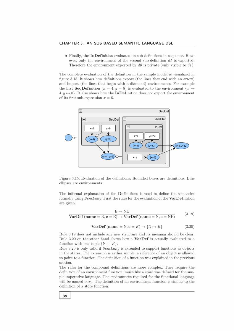
CHAPTER 3. AN SOS BASED SEMANTIC LANGUAGE DSL
• Finally, the InDef inition evaluates its sub-definitions in sequence. How-ever, only the environment of the second sub-definition d1 is exported.Therefore the environment exported by d0 is private (only visible to d1 ).
The complete evaluation of the definition in the sample model is visualized infigure 3.15. It shows how definitions export (the lines that end with an arrow)and import (the lines that begin with a diamond) environments. For examplethe first SeqDef inition (x = 4; y = 8) is evaluated to the environment {x 7→4, y 7→ 8}. It also shows how the InDef inition does not export the environmentof its first sub-expression x = 6.
Figure 3.15: Evaluation of the definitions. Rounded boxes are definitions. Blueellipses are environments.
The informal explanation of the Def initions is used to define the semanticsformally using SemLang. First the rules for the evaluation of the VarDef initionare given.
E→ NE
VarDef (name = N, e = E)→ VarDef (name = N, e = NE)(3.19)
VarDef (name = N, e = E )→ {N 7→ E} (3.20)
Rule 3.19 does not include any new structure and its meaning should be clear.Rule 3.20 on the other hand shows how a VarDef is actually evaluated to afunction with one tuple {N 7→ E}.Rule 3.20 is only valid if SemLang is extended to support functions as objectsin the states. The extension is rather simple: a reference of an object is allowedto point to a function. The definition of a function was explained in the previoussection.The rules for the compound definitions are more complex. They require thedefinition of an environment function, much like a store was defined for the sim-ple imperative language. The environment required for the functional languagewill be named envρ. The definition of an environment function is similar to thedefinition of a store function:
38

3.4. INTRODUCING THE ENVIRONMENT
envρ : String → Object
The only difference is that the name of the function is labelled with a ρ symbol.This symbol indicates that the function should only be used as an environmentand not as a store. The equation defines an environment function named envρ
that maps strings to objects. Environment functions differ from store functionin that they can only be used in the labels of transition conditions, the nextrules illustrate this fact.The usage of environment functions becomes clearer when the rules for thecompound definitions are explained. The rules for the SeqDef inition are givenbelow. Rule 3.21 is simple: it states that first d0 should be evaluated. Note thatd0 will evaluate to an environment function.
D0→ ND0
SeqDef (d0 = D0,d1 = D1)→ SeqDef (d0 = ND0,d1 = D1)(3.21)
Rule 3.22 is more complex. The pattern part SeqDef (d0 = d0ρ,d1 = D1)matches a SeqDef object where reference d0 points to a function. This isbecause variable d0ρ only binds to environment functions, not to other objects.Variable D1 will bind to a non computed Def inition object.
The transition condition also introduces new constructs: D1envρ=envρ[d0ρ]−−−−−−−−−−→
ND1. It means that D1 must be evaluated under the environment envρ [d0ρ]. Inother words: D1 will be evaluated in an environment that imports the definitionsas defined by d0.
D1env=envρ[d0ρ]−−−−−−−−−→ ND1
SeqDef (d0 = d0ρ,d1 = D1)→ SeqDef (d0 = d0ρ,d1 = ND1)(3.22)
The last rule (rule 3.23) shows how a SeqDef is eventually evaluated to anenvironment function. It also shows that the rhs of a rule may be a functionexpression. In this case it is a function override expression d0ρ [d1ρ]. Thus thefinal result of a SeqDef inition is the environment defined by d0 overridden bythe environment defined by d1.
SeqDef (d0 = d0ρ,d1 = d1ρ)→ d0ρ [d1ρ] (3.23)
The rules for the AndDef inition are almost identical to the rules of the Se-qDef inition. Rule 3.24 and 3.26 are actually completely similar to rules 3.21and 3.23 respectively.
D0→ ND0
AndDef (d0 = D0,d1 = D1)→ AndDef (d0 = ND0,d1 = D1)(3.24)
D1→ ND1
AndDef (d0 = d0ρ,d1 = D1)→ AndDef (d0 = d0ρ,d1 = ND1)(3.25)
The only difference is in rule 3.25. The sub-definitions in an AndDef inition areevaluated in the same environment; definition d1 is not aware of the environmentfunction d0ρ. This characterizes the parallel behaviour of the AndDef inition.
39
CHAPTER 3. AN SOS BASED SEMANTIC LANGUAGE DSL
AndDef (d0 = d0ρ,d1 = d1ρ)→ d0ρ [d1ρ] (3.26)
The rules for the InDef inition are similar to the rules of the SeqDef inition.The only difference is that the environment of the first sub-definition d0ρ is notexported. This is specified by rule 3.29.
D0→ ND0
InDef (d0 = D0,d1 = D1)→ InDef (d0 = ND0,d1 = D1)(3.27)
D1env=envρ[d0ρ]−−−−−−−−−→ ND1
InDef (d0 = d0ρ,d1 = D1)→ InDef (d0 = d0ρ,d1 = ND1)(3.28)
InDef (d0 = d0ρ,d1 = d1ρ)→ d1ρ (3.29)
The rules for all types of definitions are explained at this point. Definitions areonly allowed in LetExpressions. The rules for LetExpressions are not verydifficult.A LetExpression first evaluates its definitions to an environment. This is definedby rule 3.30
D→ ND
LetExp (d = D, e = E)→ LetExp (d = ND, e = E)(3.30)
If the definitions are fully evaluated to an environment pρ (represented as afunction) then the expression e is evaluated within the environment envρ [pρ].This is the environment in which the LetExpression is evaluated envρ overrid-den by the environment pρ defined by the definition in the LetExpression. Thisis shown in rule 3.31This basically means that the variables defined by the definition d are onlyvisible within expression e of the LetExpression. This is also known as thescope of the definition.
Eenvρ=envρ[pρ]−−−−−−−−−→ NE
LetExp (d = pρ, e = E)→ LetExp (d = pρ, e = NE)(3.31)
Finally when the expression e is evaluated to a computed value E (a Number)then the complete LetExpression is evaluated to that value. The environmentpρ is dropped. So the scope of pρ has ended. This behaviour is defined by rule3.32.
LetExp (d = pρ, e = E )→ E (3.32)
The rules show how expressions are evaluated in a certain environment. However,the only expression that actually needs the environment is the Var expression.A Var expression has an attribute name that refers to a name of a variable.The result of an evaluation of a Var object is the value of the variable withname name in the current environment.Rule 3.33 shows how the Var object is evaluated envρ (N), which is equals tothe value V if N 7→ V ∈ envρ.
Var (name = N)→ envρ (N) (3.33)
40
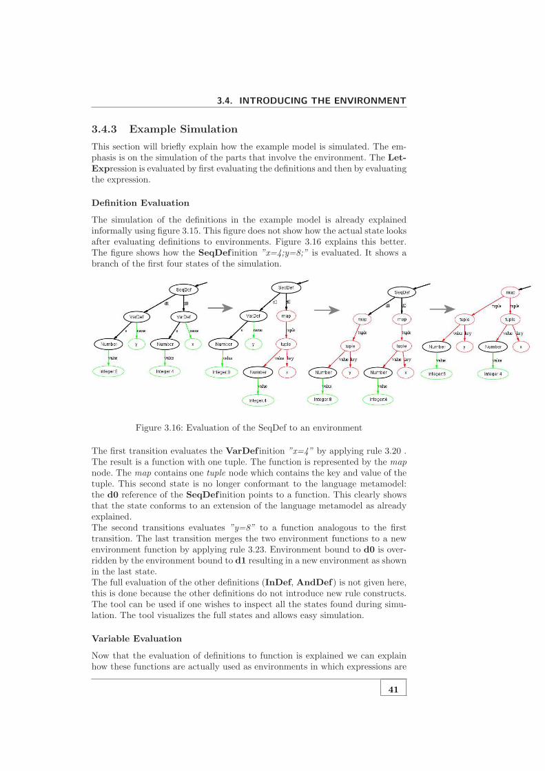
3.4. INTRODUCING THE ENVIRONMENT
3.4.3 Example Simulation
This section will briefly explain how the example model is simulated. The em-phasis is on the simulation of the parts that involve the environment. The Let-Expression is evaluated by first evaluating the definitions and then by evaluatingthe expression.
Definition Evaluation
The simulation of the definitions in the example model is already explainedinformally using figure 3.15. This figure does not show how the actual state looksafter evaluating definitions to environments. Figure 3.16 explains this better.The figure shows how the SeqDef inition ”x=4;y=8;” is evaluated. It shows abranch of the first four states of the simulation.
Figure 3.16: Evaluation of the SeqDef to an environment
The first transition evaluates the VarDef inition ”x=4” by applying rule 3.20 .The result is a function with one tuple. The function is represented by the mapnode. The map contains one tuple node which contains the key and value of thetuple. This second state is no longer conformant to the language metamodel:the d0 reference of the SeqDef inition points to a function. This clearly showsthat the state conforms to an extension of the language metamodel as alreadyexplained.The second transitions evaluates ”y=8” to a function analogous to the firsttransition. The last transition merges the two environment functions to a newenvironment function by applying rule 3.23. Environment bound to d0 is over-ridden by the environment bound to d1 resulting in a new environment as shownin the last state.The full evaluation of the other definitions (InDef, AndDef) is not given here,this is done because the other definitions do not introduce new rule constructs.The tool can be used if one wishes to inspect all the states found during simu-lation. The tool visualizes the full states and allows easy simulation.
Variable Evaluation
Now that the evaluation of definitions to function is explained we can explainhow these functions are actually used as environments in which expressions are
41

CHAPTER 3. AN SOS BASED SEMANTIC LANGUAGE DSL
evaluated. This is explained using figure 3.17.
Figure 3.17: Reading a variable from the environment
The top state in the figure shows a LetExpression for which the definition isfully evaluated to a function with two tuples ”x” 7→ Number (value = 8) and”y” 7→ Number (value = 12) (represented by the map node). The expressionx + y must be evaluated within that environment.
The transition from the top state to the bottom state is proved by rule 3.34:
42

3.4. INTRODUCING THE ENVIRONMENT
Eenvρ=envρ[pρ]−−−−−−−−−→ NE
LetExp (d = pρ, e = E)→ LetExp (d = pρ, e = NE)(3.34)
The variables pρ is bound to the environment:
pρ = {”x” 7→ Number (value = 8) , ”y” 7→ Number (value = 12)} (3.35)
For simplicity we assume that the current environment envρ is empty. Becauseit is empty we can conclude that envρ [pρ] = pρ. Variable E is bound the Bi-naryExpression and its child nodes as indicated by BinExp (· · · ) expression.The variable E is now substituted in the rule.
BinExp (· · · )envρ=pρ−−−−−→ NE
LetExp (d = pρ, e = BinExp (· · · ))→ LetExp (d = pρ, e = NE)(3.36)
The transition condition can be met by applying the rule for evaluating the lhsof a BinExp. This rule is not given for this language but it is identical to rule3.5 for the simple imperative language.
L→ NL
BinExp (lhs = L,bop = O, rhs = R)envρ=pρ−−−−−→ BinExp (lhs = NL,bop = O, rhs = R)
LetExp (d = pρ, e = BinExp (· · · ))→ LetExp (d = pρ, e = NE)(3.37)
The variable L, O and R are not filled in to keep the proof readable. L is boundto Var(name = ”y”). The transition condition L → NL can be expandedby applying rule 3.33. Also note that the new environment propagates to thetransition condition.
Var(name = ”y”)envρ=pρ−−−−−→ envρ (”y”)
BinExp (lhs = L,bop = O, rhs = R)envρ=pρ−−−−−→ BinExp (lhs = NL,bop = O, rhs = R)
LetExp (d = pρ, e = BinExp (· · · ))→ LetExp (d = pρ, e = NE)(3.38)
This concludes the proof. The result of envρ (”y”) is Number (value = 12)because ”y” 7→ Number (value = 12) ∈ envρ.All the meta-variables that were changed can now be filled in to construct thenew state. The dots (· · · ) indicate that nothing is changed with respect to theproof 3.38.
Var(name = ”y”)envρ=pρ−−−−−→ Number (value = 12)
BinExp (· · · )envρ=pρ−−−−−→ BinExp (lhs = Number (value = 12) , · · · )
LetExp (· · · )→ LetExp (d = pρ, e = BinExp (lhs = Number (value = 12) , · · · ))(3.39)
In summary this says in the new state the lhs of the BinExpression is replacedby Number (value = 12). This is exactly what has happened in the new statein figure 3.17.
43

CHAPTER 3. AN SOS BASED SEMANTIC LANGUAGE DSL
3.5 Supporting Graph Structures: Activity Diagrams
Until now we only showed that SemLang is able to define the semantics oflanguages similar to the languages for which Plotkin described the semantics.The models of these languages are always trees. This is of course a logicalconsequence when using abstract syntax trees (ASTs). The metamodel of thelanguages we introduced so far always use containment references. This preventscross references in the model and it ensures that the models are always trees.However, in MDE metamodels are also allowed to contain cross references.Therefore the models in MDE are generally graph structures. Plotkin style SOS,however, is based on EBNF and therefore the structures are always ASTs. Therules in standard SOS therefore only deal with tree structures.However, SemLang must be able to deal with graph structures. The way SemLangdeals with graph structures is illustrated by an example language for which themodels are graphs. This example language is the Activity Diagram Language.
3.5.1 MetaModel
The Activity Diagram language is a simple diagram language that can be usedto visualise the control flow of programs. This is similar to the Activity Diagramsfound in UML. An example diagram is given in figure 3.18, it represents a simplecount-to-five program. The visual syntax is taken from UML Activity Diagrams.
Figure 3.18: Concrete visual model of an Activity Diagram
There are different types of nodes in the example program. There is a start andstop node. After the start node there is an assignment node in which variable ais assigned the value 1. After the assignment node there is test node in which theexpression a = 4 acts as an condition. Depending on the value of the conditioneither the stop node is visited or another assignment a := a + 1 node is visited.The metamodel of the Activity Diagram language is given in figure 3.19. AnActivity Diagram consists of Nodes. Each node has a name, this is done forthe concrete textual syntax of the language, which will not be explained here.A node is either a StopNode or a SeqNode. A SeqNode is a node whichhas reference to a next node. A SeqNode is either a StartNode, Test node
44

3.5. SUPPORTING GRAPH STRUCTURES: ACTIVITY DIAGRAMS
or an Assignment node. Both the Test and Assignment nodes consist of anExpression. For the Test node this expression acts as an condition and for theAssignment node this acts as the value that is bound to the variable.It is important to see that the references next of SeqNode and alternativeof the Test node are cross references. This is indicated by the open arrow. Thelines that have a filled diamonds represent containment references.
Figure 3.19: Activity Diagram language metamodel
The example diagram in figure 3.18 can also be represented as an Diagramobject that conforms to the metamodel. This model is presented in figure 3.20.The new things in this model are the blue arrows. Blue arrows represent cross-references. The thick black arrows represent containment references. This isimportant to know. Also note that the black-arrows always form a tree, this isa natural result of the use of containment references.
3.5.2 Semantics
Informal Semantics
The semantics for the Activity Diagram Language is not very complex. Thesemantics of the expressions will not be explained. They are already explainedfor the different languages in the previous sections. The focus is on the semanticsof the nodes.An Activity Diagram should have one StartNode and at least one StopNode.A diagram is evaluated by moving through the nodes and by evaluating eachnode. The evaluation starts at the StartNode. Then we move to the next node.Evaluation of a diagram is complete if a StopNode is reached.An Assignment node is evaluated by first evaluating the expression e, and thenby binding the new value to the variable and moving to the next state.A Test node is evaluated by first evaluating the condition expression e. If thecondition is true the next node is taken. The alternative node is taken other-wise.This concludes an informal explanation of the semantics. However, it is impor-tant to know that a node can be evaluated multiple times; for example when
45
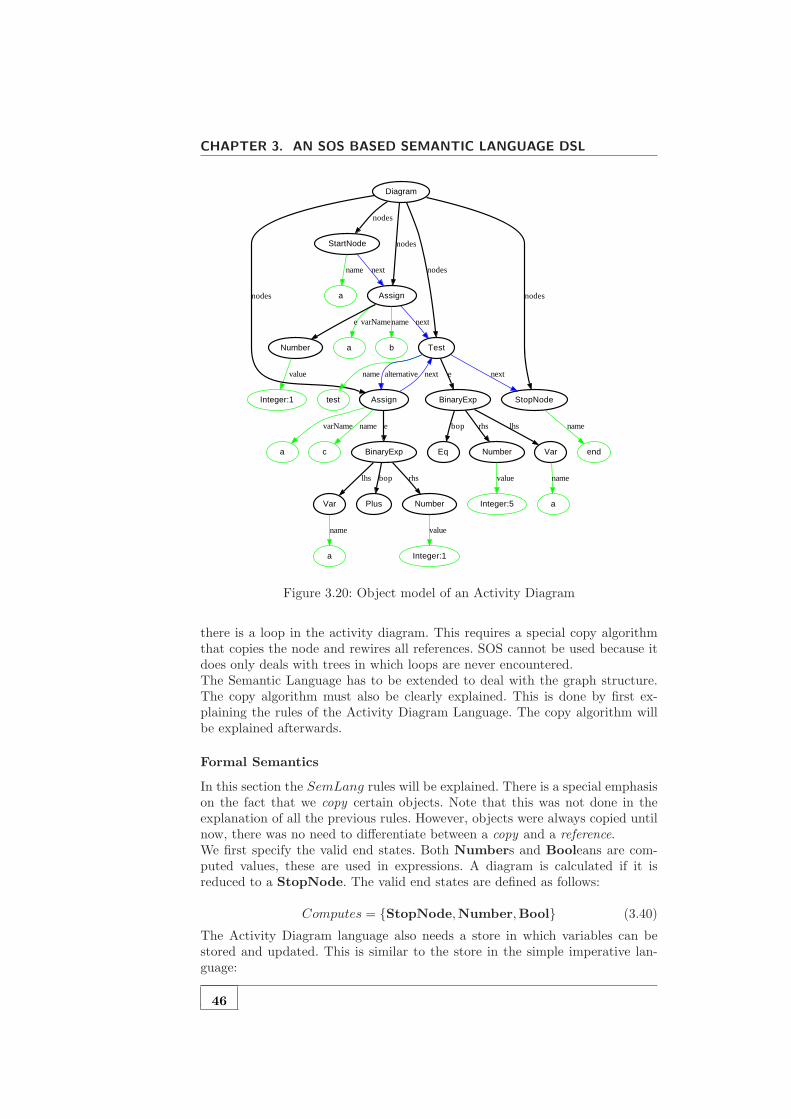
CHAPTER 3. AN SOS BASED SEMANTIC LANGUAGE DSL
Integer:1 BinaryExp
Eq
bop
Number
rhs
Var
lhs
Plus
StartNode
a
name
Assign
next
a
Integer:5
test
ba
Assign
BinaryExp
e
a
varName
c
name
Test
next
Integer:1
Number
value
bop
Number
rhs
Var
lhs value
StopNode
end
name
namevarNamee next
a
name
value
Diagram
nodes
nodes nodes
nodes
nodes
ename alternative next
name
Figure 3.20: Object model of an Activity Diagram
there is a loop in the activity diagram. This requires a special copy algorithmthat copies the node and rewires all references. SOS cannot be used because itdoes only deals with trees in which loops are never encountered.The Semantic Language has to be extended to deal with the graph structure.The copy algorithm must also be clearly explained. This is done by first ex-plaining the rules of the Activity Diagram Language. The copy algorithm willbe explained afterwards.
Formal Semantics
In this section the SemLang rules will be explained. There is a special emphasison the fact that we copy certain objects. Note that this was not done in theexplanation of all the previous rules. However, objects were always copied untilnow, there was no need to differentiate between a copy and a reference.We first specify the valid end states. Both Numbers and Booleans are com-puted values, these are used in expressions. A diagram is calculated if it isreduced to a StopNode. The valid end states are defined as follows:
Computes = {StopNode,Number,Bool} (3.40)
The Activity Diagram language also needs a store in which variables can bestored and updated. This is similar to the store in the simple imperative lan-guage:
46

3.5. SUPPORTING GRAPH STRUCTURES: ACTIVITY DIAGRAMS
store : String → Object (3.41)
Now the rules can be specified. The first rule matches the root Diagram objectand evaluates it to a copy of a StartNode (see rule 3.42). The pattern of thisrule has a new construct: NS 〈∃n ∈ StartNode〉. This means that the rule onlymatches if there exists an object n in NS that conforms to a StartNode. Thisis called existential quantification.
Diagram (nodes = NS 〈∃n ∈ StartNode〉)→ n (3.42)
If there are multiple StartNodes then this rule matches all of them. Thereforemultiple StartNodes in a single Diagram introduces nondeterminism for thefirst transition.The next rule, rule 3.43, evaluates a StartNode to a copy of the next node.
StartNode (next = N)→ N (3.43)
An Assignment node is evaluated by first evaluating the expression e. Rule3.44 defines this behaviour. It is important to note that the rhs of the rule,Assign (· · · ), is a constructor: it constructs a new object that conforms to theAssign class. All attributes and references are copied :
• varName is assigned to a copy of VN
• e is assigned to a copy of NE
• next is assigned to a copy of N
This is an important detail: after the copy algorithm is explained one will seethat this copying preserves the old Assign object if that object is in the sub-graph of the object N.
E→ NE
Assign (varName = VN, e = E,next = N)→ Assign (varName = VN, e = NE,next = N)(3.44)
The next Assignment rule (rule 3.45) simply evaluates to a copy of the nextnode. However, a new tuple is added to the store. This is identical to the storeupdates in the simple imperative language. Therefore this will not be explainedfurther.
Assign (varName = VN, e = E ,next = N)store′=store[{VN 7→E}]−−−−−−−−−−−−−−−→ N (3.45)
The first Test rule simply evaluates the condition e first. This is defined byrule 3.46. The rule looks like the first Assignment rule (rule 3.44). Again it isimportant to see that the rhs of the rule constructs a new Test object and bindscopies of NC, N, and A to e, next and alternative respectively.
C→ NC
Test (e = C,next = N,alternative = A)→ Test (e = NC,next = N,alternative = A)(3.46)
47
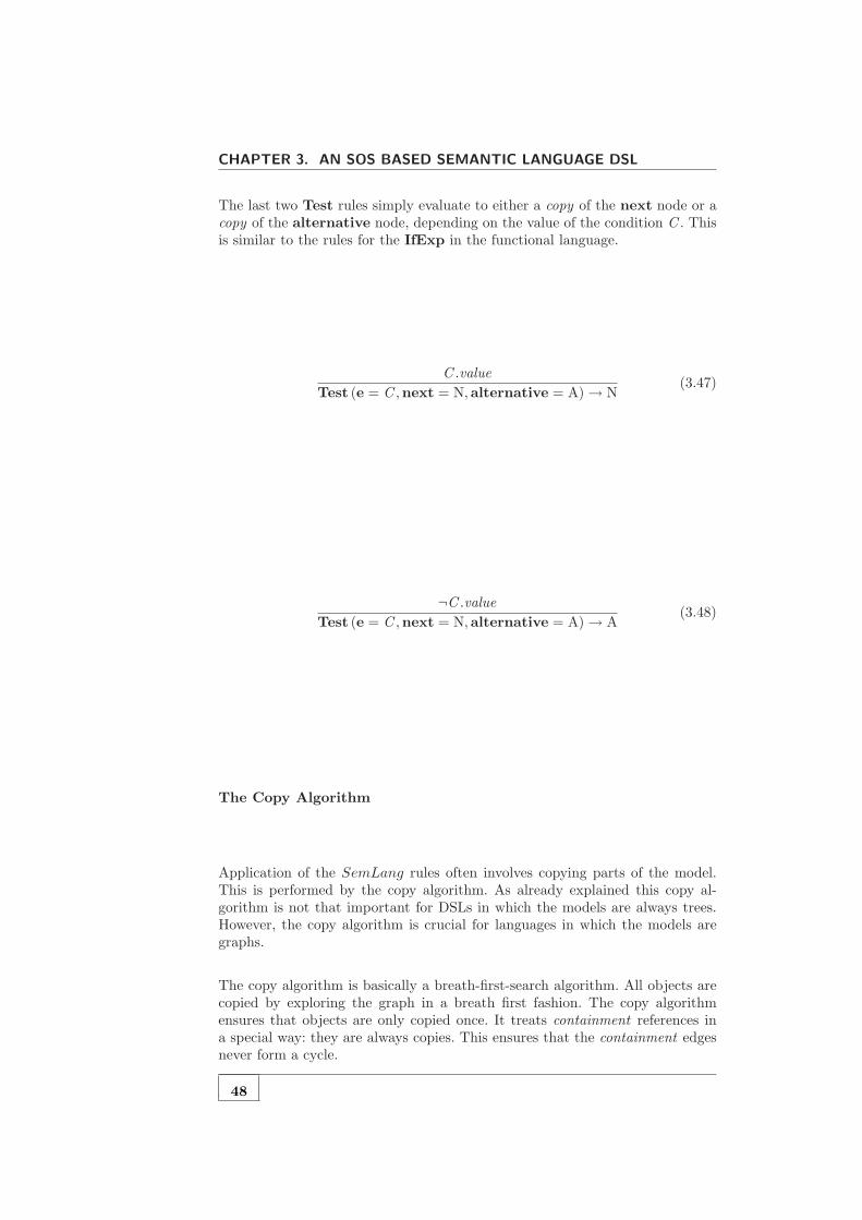
CHAPTER 3. AN SOS BASED SEMANTIC LANGUAGE DSL
The last two Test rules simply evaluate to either a copy of the next node or acopy of the alternative node, depending on the value of the condition C . Thisis similar to the rules for the IfExp in the functional language.
C .value
Test (e = C ,next = N,alternative = A)→ N(3.47)
¬C .value
Test (e = C ,next = N,alternative = A)→ A(3.48)
The Copy Algorithm
Application of the SemLang rules often involves copying parts of the model.This is performed by the copy algorithm. As already explained this copy al-gorithm is not that important for DSLs in which the models are always trees.However, the copy algorithm is crucial for languages in which the models aregraphs.
The copy algorithm is basically a breath-first-search algorithm. All objects arecopied by exploring the graph in a breath first fashion. The copy algorithmensures that objects are only copied once. It treats containment references ina special way: they are always copies. This ensures that the containment edgesnever form a cycle.
48

3.5. SUPPORTING GRAPH STRUCTURES: ACTIVITY DIAGRAMS
Copy-Algorithm(object)
1 � a map from old object to copied objects2 copies← Object→ Object3 � a queue of object that must be copied4 queue← [object]5 � a queue of objects that must be rewired6 updateQueue← []7 � perform a breath-first-copy8 while queue 6= ∅9 do object← queue.dequeue()
10 if object isA function11 then copy ← Copy-Function(object)12 copies.add(object, copy)13 else copy ← new object that conforms object.class14 copies.add(object, copy)15 � add all attributes16 for att ∈ object.attributes17 do copy.set(att, object.get(att))18 � enqueue all referenced objects19 for ref ∈ object.references20 do if object /∈ updateQueue21 then updateQueue.add(object)22 node← object.get(ref)23 � enqueue the node if it is a containment24 � or if it is not copied before25 if node /∈ queue ∧ (ref.isContainment ∨ node /∈ copies.keys)26 then queue.add(referred)27 � rewiring: makes sure all references are updated28 while updateQueue 6= ∅29 do object← updateQueue.dequeue()30 copy ← copies.getCopyOf(object)31 for ref ∈ object.references32 do node← object.get(ref)33 � make sure it refers to the copied object34 nodeCopy ← copies.getCopyOf(node)35 copy.set(ref, nodeCopy)
The copy algorithm has a same time complexity as the breath-first-search algo-rithm and is therefore O(n + e), where n is the number of nodes in the modeland e is the number of edges (references).
Copy-Function(f)
1 copy ← newfunction2 � copy each tuple3 for key 7→ value ∈ f4 do f ← f ∪ {Copy-Algorithm(key) 7→ Copy-Algorithm(value)}5 return copy
49
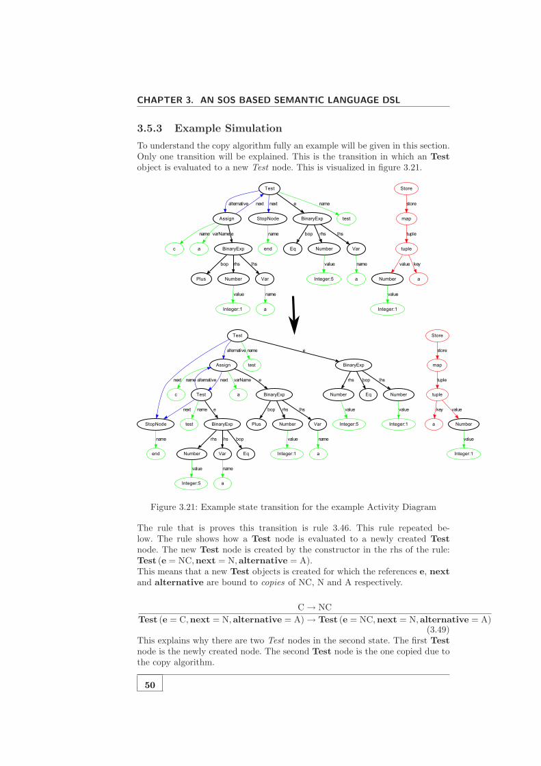
CHAPTER 3. AN SOS BASED SEMANTIC LANGUAGE DSL
3.5.3 Example Simulation
To understand the copy algorithm fully an example will be given in this section.Only one transition will be explained. This is the transition in which an Testobject is evaluated to a new Test node. This is visualized in figure 3.21.
Figure 3.21: Example state transition for the example Activity Diagram
The rule that is proves this transition is rule 3.46. This rule repeated be-low. The rule shows how a Test node is evaluated to a newly created Testnode. The new Test node is created by the constructor in the rhs of the rule:Test (e = NC,next = N,alternative = A).This means that a new Test objects is created for which the references e, nextand alternative are bound to copies of NC, N and A respectively.
C→ NC
Test (e = C,next = N,alternative = A)→ Test (e = NC,next = N,alternative = A)(3.49)
This explains why there are two Test nodes in the second state. The first Testnode is the newly created node. The second Test node is the one copied due tothe copy algorithm.
50
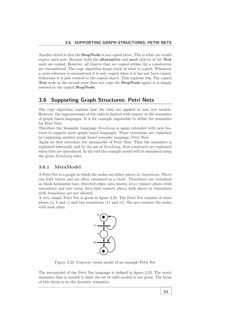
3.6. SUPPORTING GRAPH STRUCTURES: PETRI NETS
Another detail is that the StopNode is not copied twice. This is what one wouldexpect until now. Because both the alternative and next objects of the Testnode are copied. However, all objects that are copied within the a constructorare remembered. The copy algorithm keeps track of what is copied. Whenevera cross reference is encountered it is only copied when it is has not been copied.Otherwise it is just rewired to the copied object. This explains why The copiedTest node in the second state does not copy the StopNode again: it is simplyrewired to the copied StopNode.
3.6 Supporting Graph Structures: Petri Nets
The copy algorithm explains how the rules are applied to non tree models.However, the expressiveness of the rules is limited with respect to the semanticsof graph based languages. It is for example impossible to define the semanticsfor Petri Nets.Therefore the Semantic Language SemLang is again extended with new fea-tures to support more graph based languages. These extensions are explainedby explaining another graph based semantic language: Petri Nets.Again we first introduce the metamodel of Petri Nets. Then the semantics isexplained informally and by the use of SemLang. New constructs are explainedwhen they are introduced. In the end the example model will be simulated usingthe given SemLang rules.
3.6.1 MetaModel
A Petri Net is a graph in which the nodes are either places or transitions. Placescan hold tokens and are often visualized as a circle. Transitions are visualizedas black horizontal bars. Directed edges (also known arcs) connect places withtransitions and vice versa. Arcs that connect places with places or transitionswith transitions are not allowed.A very simple Petri Net is given in figure 3.22. The Petri Net consists of threeplaces (a, b and c) and two transitions (t1 and t2 ). Six arcs connect the nodeswith each other.
Figure 3.22: Concrete visual model of an example Petri Net
The metamodel of the Petri Net language is defined in figure 3.23. The staticsemantics that is needed to limit the set of valid models is not given. The focusof this thesis is on the dynamic semantics.
51
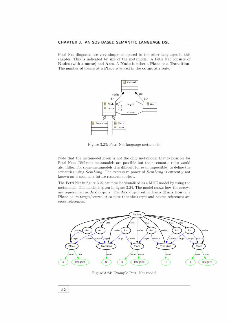
CHAPTER 3. AN SOS BASED SEMANTIC LANGUAGE DSL
Petri Net diagrams are very simple compared to the other languages in thischapter. This is indicated by size of the metamodel. A Petri Net consists ofNodes (with a name) and Arcs. A Node is either a Place or a Transition.The number of tokens at a Place is stored in the count attribute.
Figure 3.23: Petri Net language metamodel
Note that the metamodel given is not the only metamodel that is possible forPetri Nets. Different metamodels are possible but their semantic rules wouldalso differ. For some metamodels it is difficult (or even impossible) to define thesemantics using SemLang. The expressive power of SemLang is currently notknown an is seen as a future research subject.
The Petri Net in figure 3.22 can now be visualised as a MDE model by using themetamodel. The model is given in figure 3.24. The model shows how the arrowsare represented as Arc objects. The Arc object either has a Transition or aPlace as its target/source. Also note that the target and source references arecross references.
Place
b
name
Integer:0
count
Place
c
name
Integer:1
count
Place
a
name
Integer:1
count
t1t2
Petrinet
nodesnodes nodesArc
arcs
Arc
arcs
Transition
nodes Arc
arcs
Arc
arcs
Arc
arcs
Transition
nodes Arc
arcs
source targettarget source
name
sourcetarget target source targetsource
name
sourcetarget
Figure 3.24: Example Petri Net model
52

3.6. SUPPORTING GRAPH STRUCTURES: PETRI NETS
3.6.2 Semantics
Informal Semantics
The Transition nodes in a Petri Net can fire if they are enabled. A Transitionis enabled if each Place for which there is an Arc pointing to the Transitionhas at least one token. The firing of a Transition is a two-step process. Firstit consumes one token in each Place that points to the Transition. Thenit produces one token for each Place if there is an Arc pointing from theTransition to the Place.Transitions do not fire simultaneously. However, multiple Transitions can beenabled. This makes Petri Nets non-deterministic.An example simulation of the example model is shown in figure 3.25. There arefive states (labelled S1 to S5 ). First Transition t1 fires: it first consumes onetoken in Place a (at state S2 ). Then it produces a token in both a and b (atstate S3 ). Note that the firing of a Transition involves two states.Sequentially Transition t2 fires. It consumes a token in both b and c (stateS4 ) and then produces a token in Place c (state S5 ).
Figure 3.25: Petri Net example simulation
Note that the firing of a Transition is broken into two steps. The semanticscould also be defined in a way that the firing of a Transition only involves onestate transition in which the consuming and producing executes simultaneously.We choose to break it down into two steps to keep the rules smaller.
Formal Semantics
The SemLang semantics for Petri Nets only consists of two rules. One rule forthe consuming of tokens and one rule for the producing of tokens. However,these two rules are rather complex. Both rules also use a store named firing.This store is a singleton: it only stores one object. The firing singleton storesthe current Transition that is firing. It is defined as follows:
firing : Transition
This is a new addition to SemLang: functions (stores and environments) canalso be singletons.
53
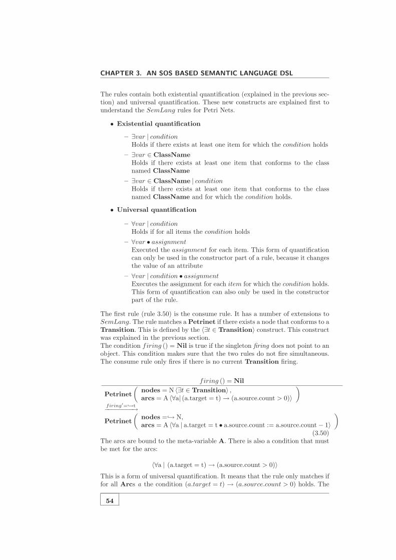
CHAPTER 3. AN SOS BASED SEMANTIC LANGUAGE DSL
The rules contain both existential quantification (explained in the previous sec-tion) and universal quantification. These new constructs are explained first tounderstand the SemLang rules for Petri Nets.
• Existential quantification
– ∃var | conditionHolds if there exists at least one item for which the condition holds
– ∃var ∈ ClassNameHolds if there exists at least one item that conforms to the classnamed ClassName
– ∃var ∈ ClassName | conditionHolds if there exists at least one item that conforms to the classnamed ClassName and for which the condition holds.
• Universal quantification
– ∀var | conditionHolds if for all items the condition holds
– ∀var • assignmentExecuted the assignment for each item. This form of quantificationcan only be used in the constructor part of a rule, because it changesthe value of an attribute
– ∀var | condition • assignmentExecutes the assignment for each item for which the condition holds.This form of quantification can also only be used in the constructorpart of the rule.
The first rule (rule 3.50) is the consume rule. It has a number of extensions toSemLang. The rule matches a Petrinet if there exists a node that conforms to aTransition. This is defined by the 〈∃t ∈ Transition〉 construct. This constructwas explained in the previous section.The condition firing () = Nil is true if the singleton firing does not point to anobject. This condition makes sure that the two rules do not fire simultaneous.The consume rule only fires if there is no current Transition firing.
firing () = Nil
Petrinet
(
nodes = N 〈∃t ∈ Transition〉 ,arcs = A 〈∀a| (a.target = t)→ (a.source.count > 0)〉
)
firing′=→t−−−−−−−−→
Petrinet
(
nodes =→ N,arcs = A 〈∀a | a.target = t • a.source.count := a.source.count− 1〉
)
(3.50)The arcs are bound to the meta-variable A. There is also a condition that mustbe met for the arcs:
〈∀a | (a.target = t)→ (a.source.count > 0)〉
This is a form of universal quantification. It means that the rule only matches iffor all Arcs a the condition (a.target = t) → (a.source.count > 0) holds. The
54

3.6. SUPPORTING GRAPH STRUCTURES: PETRI NETS
→ symbol in the condition is the logical implication operator. Intuitively thismeans that the rule only matches if all Places that point to the Transition thave at least one token.The constructor also has a universal quantification construct. However, this con-struct also has an assignment in it. The meaning of the universal quantificationis that for each Arc a for which the condition a.target = t holds the assignmenta.source.count := a.source.count− 1 is executed.
〈∀a | a.target = t • a.source.count := a.source.count− 1〉
The effect of this is that for each source Place the count attribute is decre-mented by one. This is exactly what should happen when the tokens are con-sumed.Another new construct is the use of the → symbol. This symbol can be placedbefore meta-variables and indicates that an object should not be copied. Avariable that is preceded by the → is called a referenced variable. For example→ N indicates that the object(s) in N should be referenced and not be copied.The copy-algorithm is aware of all objects that are referenced within a con-structor. Whenever it performs a copy it will remember all referenced objectsand rewire all references to make sure they point to the referenced objects. Anexample will make this easier to understand.Suppose we have a constructor that looks like Petrinet (nodes =→ N,arcs = A).When the Arcs in A are copied it will not copy references to Node objects ifthe Node is in N. Instead it will make sure that the reference will point to theNode in N.The consume rule also updates the store. This is defined by firing′ =→ t. Itmakes the firing singleton point to a reference of the Transition object t.The produce rule (rule 3.51) should produce one token in all target Places.It only matches if the condition ¬(firing () = Nil) holds: i.e. it only matcheswhen there is a Transition firing.
¬(firing () = Nil)
Petrinet (nodes = N,arcs = A)firing′=Nil
−−−−−−−−→
Petrinet
(
nodes =→ N,arcs = A 〈∀a | a.source = firing () • a.target.count := a.target.count + 1〉
)
(3.51)The only new thing in the produce-rule is the universal quantification with anassignment in the constructor of the rule:
〈∀a | a.source = firing () • a.target.count := a.target.count + 1〉
This makes sure that for all target Places the count attribute is incrementedby one. This is exactly what should happen: it produces one token in the targetPlaces.
3.6.3 Example Simulation
The meaning of the new constructs is easier to understand by giving an examplesimulation of the model. The simulation of the Petri Net given in figure 3.25 is
55
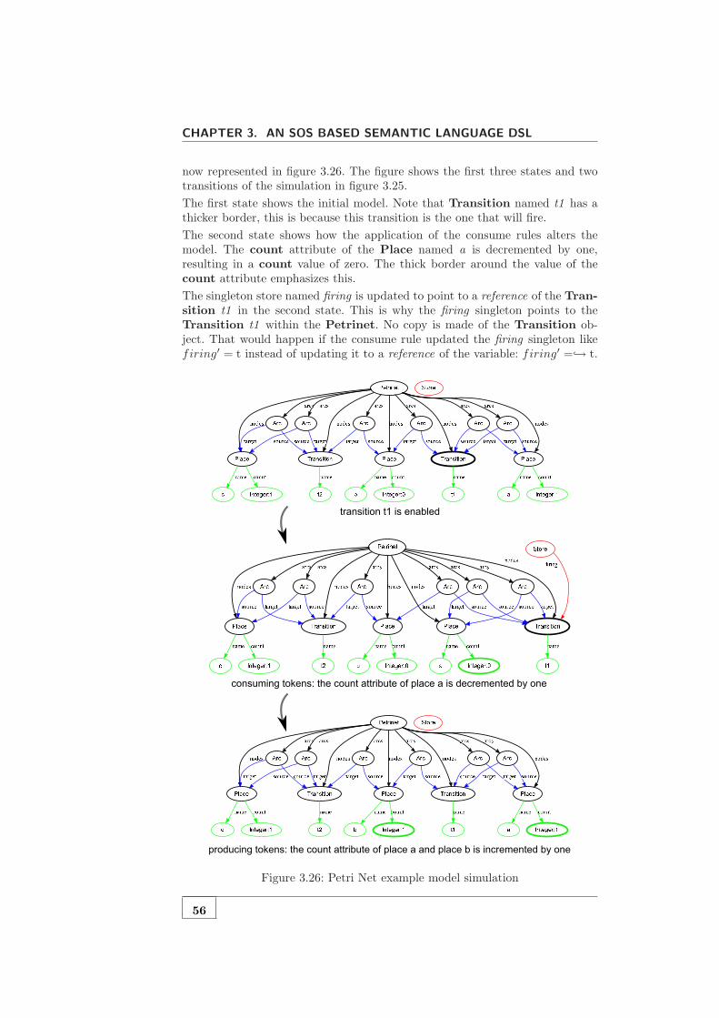
CHAPTER 3. AN SOS BASED SEMANTIC LANGUAGE DSL
now represented in figure 3.26. The figure shows the first three states and twotransitions of the simulation in figure 3.25.
The first state shows the initial model. Note that Transition named t1 has athicker border, this is because this transition is the one that will fire.
The second state shows how the application of the consume rules alters themodel. The count attribute of the Place named a is decremented by one,resulting in a count value of zero. The thick border around the value of thecount attribute emphasizes this.
The singleton store named firing is updated to point to a reference of the Tran-sition t1 in the second state. This is why the firing singleton points to theTransition t1 within the Petrinet. No copy is made of the Transition ob-ject. That would happen if the consume rule updated the firing singleton likefiring′ = t instead of updating it to a reference of the variable: firing′ =→ t.
Figure 3.26: Petri Net example model simulation
56

3.7. CONCLUSION
The third state shows the result of the produce rule. The singleton firing pointsto nothing (internally it points to Nil). The places named a and b are updated:their count attribute is incremented by one.Another important thing to notice is that the effect of the reference symbol→ in the constructor of both rules. The Arc children of the Petrinet objectare not copied but referenced. If they were copied it would mean that all Nodeobjects will be copied twice; firstly when all Arcs are copied, and secondly whenall Node children of the Petrinet are copied. This is clearly not desirable forPetri Nets; the graph must be kept intact. This is exactly why the referencesymbol → is introduced. It allows the specifier of the rule to specify whenobjects must be copied or referenced
3.7 Conclusion
This chapter showed in an informal but detailed way how SOS can be adaptedin order to make it useful in an model driven context. The first few sectionsshowed how the semantic language SemLang supports the specification of thesemantics of tree based languages.We showed how SemLang could be used to specify the semantics for imper-ative and functional languages. A broad range of programming constructs aresupported. It showed how SemLang can be used to specify the semantics forexpressions, stores and declarations.SemLang can also be used for the definitions of functions and (recursive) func-tion invocation. Different parameter passing techniques like pass by reference,by value and by name are also supported. These techniques are not explained inthis chapter but they do not introduce new constructs in the rules of SemLang.For more details we refer to the disc in the appendix A. The disc has a collectionof example DSLs with their semantics specified in SemLang.This chapter also showed how SemLang supports the specification of the se-mantics of certain graph based languages. This is an extension to the Plotkinstyle SOS, as it only supports tree based states. The following additions to SOSwere needed to support the graph based languages.
• An explanation of the copy algorithm for graphs
• Support for referencing instead of copying
• Support for existential and universal quantification
These additions increased the expressiveness of SemLang and makes SemLangapplicable to more languages (tree based and certain graph based languages).However, it is important to understand that SemLang cannot be used for anygraph based languages. The expressiveness of SemLang compared to other ap-proaches is not researched and therefore still an open issue. More discussing onthe the expressiveness can be found in chapter 6.
57


4Formalizing the Semantic Language DSL
4.1 Introduction
This chapter provides a mathematical foundation for the Semantic Languagepresented in the previous chapter. The formalization is based on formalizationof SOS as described in [MRG07, AFV01]. Graph theory is also used to formalizemodels and states.First a formalization of the semantic domain is given. The semantic domain ofSOS in general is a labelled transition system (LTS). The states and structureof the LTS is given in the first section.Sequentially we formalize the structure of SemLang models. The last sectiondescribes how a SemLang model specifies a LTS. This is based on the fact thatan SOS description can be seen as a Transition System Specification (TSS). ATSS specifies the valid set of LTS for a specific language.
4.2 The Transition System
The semantic domain for SOS and therefore also for SemLang is a terminalLTS, also called a Labelled Terminal Transition System (LTTS).
Definition 9 (Labelled Terminal Transition System) A LTTS is a quadru-ple (Q,T,A,→) with Q as set of states, a set A of labels α, a relation →⊆
Q × A × Q of labelled transitions ((s, α, s‘) is written as sα−→ s‘), and a set
T ⊆ Q of terminal configurations such that sα−→ s‘ implies s /∈ T
The set of states Q plays an important role. As explained in the previous chapterthe states are extended models. In the previous chapter the states were visualisedas graphs, however a formal definition for a state was not given.The LTTS also includes a set of labels A. Labels are used in LTTSs are useful forconcurrency and interactivity. However in this thesis we did not focus on thoseaspects. Therefore an empty set will be used for the labels A = ∅. A transitiontherefore has no label and is written as s→ s‘.
4.2.1 Models as graphs
To formalize the states we must first formalize the MDE models. This is becausestates are essentially extended models. The visual representation of the examplemodels in the previous chapters are graphs. In fact they are a special kind of
59

CHAPTER 4. FORMALIZING THE SEMANTIC LANGUAGE DSL
graph named directed multigraphs (this follows the definition of a model insection 2.2.2) A directed multigraph is basically a graph which allows self-loopsand duplicated edges.
Definition 10 (Directed MultiGraph) A directed multigraph or multidigraphG is a pair (V,E), where V is a set of vertices, and E is a multiset of orderedpairs {u, v} such that u, v ∈ V (the edges of G).
A model however is not exactly a directed multigraph. The edges in models havea name and are called references. There are also two categories of references:containment references and cross references.Containment references are references which model a containment relationshipbetween two objects. They are not allowed to contain cycles: a model with onlycontainment references is always a tree or a set of trees.Cross references are the references that are not containment references. Crossreferences do not have the constraint for cycles.In section 2.2.2 a formal definitions for a model was given. A new definition for amodel is given below. This new definition is useful for the definition of the statesQ of the LTTS in the semantic domain. So this formal definition is meant tobe used in the formalization of SemLang. It does not capture the relationshipbetween a model and its metamodel formally.
Definition 11 (Model) A model M is a quadruple (O, o1, A,R) where
• O is a set of objects or nodes which also contains a set of primitives P ⊂ O
• o1 ∈ O is the main node
• A is a set of labels
• R is the set of references which is a relation R ⊆ O × A × O of orderedtriples {o, α, o′}. R is partitioned into a set Ra of attributes, a set Rc ofcontainment references and a set Rr of cross references (R = Ra∪Rc∪Rr
and they are also pairwise disjoint Ra∩Rc = ∅, Ra∩Rr = ∅ and Rc∩Rr =∅)
We require the following conditions on a model M .
• o ∈ P → ¬∃{o, α, o′} ∈ R, i.e all primitives are leaf nodes
• {o, α, o′} ∈ Ra → o′ ∈ P , i.e all attribute references refer to primitives
• The graph representation of a model is a connected graph
• The graph representation of a model in which the Rr edges are removed iscalled a tree (a connected graph without cycles)
Sequentially the definition of the model of an object o is given. The model of anobject o is basically a model which contains all the objects that can be reachedfrom object o. This definition is given because it is used in the next sections ofthis chapter.
Definition 12 (Model of an Object) Given a model (O, o1, A,R). The modelof an object o ∈ O denoted Model(o) is a model (Omodel, o, Amodel, Rmodel) inwhich:
60

4.2. THE TRANSITION SYSTEM
• Omodel = {x ∈ O | Path(x, o)}
• Rmodel = {(o1, αo2) ∈ R | o1 ∈ Omodel ∧ o2 ∈ Omodel
• Amodel = {α ∈ A | (x, α, y) ∈ Rmodel}
The definition shows that a model always has a single entry point o1, calledthe main object. Another important aspect of models is that the subgraphwhich only contains containment references Rc is always a tree. This is a logicalconsequence from the fact that containment references model a containmentrelationship.Note that the formal definition is a simplification of a model in the sense ofEMF and ECORE [EMF, ECO]. The ECORE metametamodel includes moreproperties on references and model elements. It also supports lists. These fea-tures are not formalized to keep things to the essential core of models and toomit trivial details.The definition does not capture the relation between a model and its metamodel.However, each object node o ∈ O implicitly refers to its metaclass. This isimplicitly done by giving the object a name that equals the name of its metaclass.The last two conditions in the definition of a model refer to the graph repre-sentation of a model. This is because models are essentially a special type ofdirected graphs. This allows the use of all definitions and theories found in graphtheory. The graph representation of a model is given below.
Definition 13 (MultiDiGraph representation of a Model) A model M =(O, o1, A,R) can be represented as a multidigraph G = (V,E) by the followingmapping
• O → V , i.e. all objects are vertices
• {o, α, o′} ∈ R→ {o, o‘} ∈ E, i.e. all references are edges
4.2.2 State representation
The previous chapter informally explained that states are essentially extendedmodels. This is analogous to the Plotkin style SOS in which states are essentiallysentences of a value-added syntax. The main extension to models is the use ofstores and environment which are represented as functions.
Definition 14 (Function) A function E is a injective function E : O → Ofrom object to objects.
To support imperative languages a store is needed in which values can be stored,this was explained in section 3.3 in the previous chapter and can also be found in[Plo81]. This requires that a state must have some sort of construct to supportstores. This is done by adding a set of functions that is separate from the model.Functional languages and imperative languages that support scope on the otherhand need an environment. The previous chapter informally explained that theseenvironments are functions that can be part of the extended model.States are models with these two extensions. Formally they can be defined asfollows.
61

CHAPTER 4. FORMALIZING THE SEMANTIC LANGUAGE DSL
Definition 15 (State) A state S is a tuple (E,S,O,M) in which E and Sare sets of environments, O is a set of objects, M is a model (OM , o1, A,R) forwhich OM ⊆ O ∪ E and E ⊂ OM
• E is called the set of environment functions env : O → O
• S is called the set of store functions store : O → O
• O is called the set of objects
A model can directly be represented as a state. This transformation is neededto transform the initial model to the initial state. It is also useful for some otherdefinitions.
Definition 16 (State representation of a Model) Given a model M = (OM , o1, A,R).The state of this model, denoted Model2State(M), is (E,S,O,M) in whichE = S = ∅ and O = OM .
Using the definition of a model as an object we can give a definition of the staterepresentation of an object. This transformation from object to state is neededfor describing the semantic language.
Definition 17 (State representation of an Object) Given an object o thestate of this object, denoted Object2State(o), equals Model2State(Model(o))
4.3 The Transition System Specification
A SemLang model specifies the semantics of a certain DSL. The semantic do-main of SemLang is an LTTS. Therefore a SemLang model is essentially aspecification for a LTTS. This is why SemLang models are called TransitionSystem Specifications (TSS). TSSs were introduced in section 2.6 about SOS,however in order to formalize how SemLang specifies a LTTS we must firstformalize the SemLang models.
4.3.1 SemLang Models
A SemLang specification is a model itself and therefore the general definition fora model can be used. However, this general definition is not useful for defininghow a SemLang model specifies a LTTS. Therefore we use a different definition.A SemLang model consists of a set of predicates over terminal states, a set offunctions that can act like stores or environments, and a set of rules.
Definition 18 (SemLang Model) A SemLang model is a tuple (E,Fenv, Fstore, R)in which E is a set of predicates over end states, Fenv a set of functions (calledenvironment functions), Fstore a set of functions (called store functions) and Ra set of rules.
For each predicate P ∈ E and state S ∈ Q then S is an end state if and only ifP (S). The functions in a SemLang model are partitioned in environment andstore functions. This is done because each type of function is used differently asexplained in the previous chapter.
62
4.3. THE TRANSITION SYSTEM SPECIFICATION
In order to define the rules we must first define terms that are used in the rules.Terms are simple patterns which match an object or construct an object. Aterm always refers to a metaclass and may also contain meta-variables whichare in the set V ar.
Definition 19 (Meta Variables) The set of meta-variables V ar is partitionedset of normal variables x, y, z · · · and a set of computed variables x , y , z · · ·
The distinction between normal and computed variables is needed because somemeta-variables should only bind to computed objects. A computed object is anobject for which the state of that object is an end state, i.e. an object o forwhich P (Object2State(o)) holds. Computed variables only match computedobjects. Computed variables can be recognized by their italic typesetting.The terms defined here are analogous to the term algebras as defined by Acetoet al [AFV01]
Definition 20 (Term) The set of terms Π(MM) over a metamodel MM anda set of meta-variables V ar is the least set such that:
• each x ∈ V ar is a term
• ClassName(r1 = T1, · · · , rn = Tn) is a term, if ClassName is thename of a metaclass m in MM , r1, · · · , rn are a subset of the attributesand references of the metaclass m or of a superclass of m and T1, · · · ,Tn
are terms
Definition 21 (1-Level Deep Term) A term ClassName(r1 = T1, · · · , rn =Tn) is 1-level deep if T1, · · · ,Tn ∈ V ar.
Definition 22 (Variables in a Term) A variable x ∈ V ar is in a term t(written as x ∈ t) if
• either x = t
• or t = ClassName(r1 = T1, · · · , rn = Tn) and there is an i ≤ n forwhich x ∈ Ti
Definition 23 (Closed Term) A term t is called a closed term if there areno variables x ∈ V ar for which x ∈ t holds. Otherwise the term is called anopen term.
Notice that r1, · · · , rn are not required to contain all the attributes and refer-ences of the metaclass m: some attributes or references may be skipped. Alsonote that r1, · · · , rn may also be attributes or references of a superclass of m:terms are aware of the inheritance in the metamodel MM .Terms were already used in the rules in the previous chapter. Some sample termsare listed below:
• BinExp (lhs = l ,bop = o, rhs = r)
– A term for metaclass named BinExp with meta-variables l , o and r
• IfExp (e0 = e0, e1 = e1, e2 = e2)
63

CHAPTER 4. FORMALIZING THE SEMANTIC LANGUAGE DSL
– A term for metaclass named IfExp with meta-variables e0, e1 and e2
The definition of a the set of terms Π(MM ) for a metamodel MM can now beused to give the definition of a rule for a specific metamodel.
Definition 24 (Rule) Let MM be a metamodel, let t, t′ range over Π(MM),let x and x′ range over V ar in which x ∈ t and x′ ∈ t′. A rule is a tuple (H,C)
where H is a set of premises xα−→ x′ and predicates P (x). C is the conclusion
which is of the form tβ−→ t′ in which:
• the lhs term of the conclusion is 1-level deep and is called the pattern ofthe rule
• the rhs term of the conclusion is called the constructor of the rule
A rule is written asH
C
Not all rules in the previous chapter fit in this definition. However the essentialparts of a rule are captured in this definition. We do not aim at full formal-ization of the SOS language. The aim of the formalization is to give a soundmathematical basis that captures the essential features of SemLang.The constructs that were used in the previous chapter but which are not formal-ized include: lists and universal and existential quantification over lists, func-tions, singleton functions and variable references.The labels α and β were used in the previous chapter to update functions. Theα label in a premise of a rule was used to update an environment functions. Theβ label in the conclusion was used to update store functions. This is similar tothe Modular SOS (MSOS) approach taken by Mosses [Mos99, Mos02, Mos04,Mos06]. The next section, in which we will prove transitions in the LTTS, doesnot take these labels into account. Again this is done to keep the formalizationsmall and understandable.
4.3.2 Proving Transitions
A SemLang model specifies a LTTS and is therefore a TSS. Until now weformalized the states Q of the LTTS and the SemLang models. A SemLangmodel specifies the transitions in the LTTS. A transition s
α−→ s‘ in the LTTS
is proved by a set of rules in the SemLang model. This proof is called the prooftree.The proof trees in SemLang are essentially the same as the proof trees usedin SOS. The main difference between SOS and SemLang is the fact that thestates in SemLang are special kinds of graphs (explained in section 4.2.2). Thedifference in state representation has an impact on the TSS. A SemLang TSSdiffers from a SOS TSS. This also changes the way a proof tree is constructed.Before we define a proof tree we must first define how the pattern term of arule matches a state, and how the constructor term of a rule constructs a state.Both the pattern term and constructor term may be open terms (which containvariables). These variables are used in a so called binding σ. A binding essentiallybinds variables to objects.
64
4.3. THE TRANSITION SYSTEM SPECIFICATION
Definition 25 (Binding) Given an model (O, o1, A,R). A binding for thismodel is a mapping σ : V ar → O.
Definition 26 (Fully Bounded Term) Given a term t and a binding σ. Theterm t is fully bound in σ if for all variables x ∈ t there exists a tuple (x, o) ∈ σ
The pattern term of a rule matches some objects. If an object o is matched abinding is created that binds all free variables in the pattern term to the directneighbour objects of o.
Definition 27 (Term Model Matching) Given a term t and a model m =(O, o1, A,R). Match(t,m) = σ holds if the term t = ClassName(r1 = x1, · · · , rn =xn) matches the model m if o1 is an instance of the metaclass named ClassName.The result of the matching is an binding σ such that if ri point to an object oi
(i.e. (o1, ri, oi) ∈ R) then (xi, oi) ∈ σ.
The constructor term of a rule is a term which constructs a new model. Whena model is constructed the copy algorithm as explained in section 5.4 is used.
Definition 28 (Term Model Construction) Given a term t which is fullybound in a binding σ. The construction of the term is an model (O, o1, A,R) =Construct(t) such that:
• if t ∈ V ar then the construction is a model which is a copy of the modelrepresentation of σ(t)
• If t = ClassName(r1 = T1, · · · , rn = Tn) then the construction is amodel in which object o1 conforms to the metaclass named ClassName.Each reference ri of object o1 is bound to the construction of term Ti. Thesets O,A and R only contain elements which are connected to o1
The definitions for matching and construction of states are needed to setupa proof tree. The definition for a proof tree looks like the proof trees in SOSexplained by [AFV01, MRG07, Mos04]. The proof tree for a transition is calleda finite upwardly branching tree.
Definition 29 (Transition Proof Tree) Given a metamodel MM, a set of allpossible states QMM for MM , t, t′ which range over Π(MM), a SemLang modelfor metamodel MM with a set of rules R which specifies an LTTS (Q,T,A,→).
A transition is sα−→ s‘ is only in → if and only if a finite upwardly branching
tree can be formed satisfying the following conditions:
1. all nodes are labelled by elements of QMM ×A×QMM
2. the root node is labelled by sα−→ s‘
3. for each n-ary node labelled s1α−→ s2 there is a rule H
tβ
−→t′and an inter-
pretation of the meta-variables that occur in it such that Match(t, s1) = σ
and Construct(t′) = s2. For each premise xα−→ x′ ∈ H there is a la-
belled branch sbα−→ s′b such that σ(x) = sb and a rule with constructor
term t′b such that σ(x′) = Construct(t′b). Each predicate P (x) ∈ H musthold.
65
CHAPTER 4. FORMALIZING THE SEMANTIC LANGUAGE DSL
4.4 Conclusion
This chapter provides a mathematical foundation for SemLang. It shows thatSemLang relies on graph theory and on the foundations of SOS given by dif-ferent authors [AFV01, MRG07, Mos04].The semantic domain of SemLang are labelled terminal transition systemsLTTS. We showed that the states are special kind of graph in which the objectsand edges have special properties. The most important structures of SemLangmodels were also formalized.It also became clear that SemLang models are essentially Transition SystemSpecifications (TSSs). The mapping from a SemLang model to a LTTS wasalso given by defining the states in the LTTS. The mapping from the TSS tothe transitions in the LTTS can be done by setting up prove trees. Again thisapproach is similar to the approach in SOS.An important difference between SOS and SemLang is that the terms havea special task in SemLang. The terms in SemLang either match models orconstruct new models. By setting up a prove tree in the current state s1 bymatching models with the pattern terms in the rules, one can construct the newstate by construction new models by using the constructor terms in the rules.This chapter does not formalize all constructs and features of SemLang. Theformalization is kept to the essential parts to keep it understandable. The maingoal of the formalization is to give a formal basis for SemLang. The focus ofthis thesis is on the pragmatical aspects of SemLang. However this chapter alsoshows that there is a formal basis on which SemLang depends on.
66
5Semantic Engine: Tool for the Semantic
Language
5.1 Introduction
This chapter presents the implementation of the tool. The tool is called Semantic
Engine and consists of an engine which is able to simulate models. An userinterface is built upon the engine and provides better usability and supportsvisualization of the states.This chapter begins with a list of requirements for the tool in section 5.2. Section5.3 explains the architecture of the tool. Both a high level architecture as wellas a more detailed level architecture description is given.Section 5.4 is devoted to the quality attributes of the tool and is divided intoruntime and non-runtime quality attributes. The last section concludes thischapter.
5.2 Requirements
Software systems are created to solve a problem in a problem domain. Theproblem can be decomposed into sub-problems from which requirements can bederived. The system solves the problem if it implements all the requirements.The tool can be used to simulate models given a semantic specification. Thereis a list of requirements for the tool. However, these requirements are less strictbecause the tool is a proof of concept. Therefore we will not give a detailed listof requirements; only some explicit high level requirements will be given.The main functional requirement of the tool is that it must be able to simulatemodel given a semantic specification. This, in turn, requires that the semanticsfor SemLang are implemented. Other, less important, functional requirementsare that the tool must support state inspection and proof tree construction. An-other feature that can be implemented is step-by-step simulation (debugging).Non-functional requirements do not deal with the function of the tool. Theserequirements are less strict because the tool is just a proof of concept. How-ever, this does not mean that there are no non-functional requirements. Theperformance of the tool is for example important because the tool is useless ifthe simulation is very slow. The documentation of the tool is also important,because this facilitates future extensions and future research. Usability and ex-tensibility are also non-functional requirements are important.
67
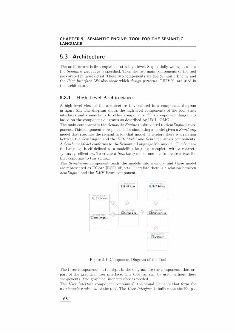
CHAPTER 5. SEMANTIC ENGINE: TOOL FOR THE SEMANTIC
LANGUAGE
5.3 Architecture
The architecture is first explained at a high level. Sequentially we explain howthe Semantic Language is specified. Then the two main components of the toolare covered in more detail. These two components are the Semantic Engine andthe User Interface. We also show which design patterns [GHJV00] are used inthe architecture.
5.3.1 High Level Architecture
A high level view of the architecture is visualised in a component diagramin figure 5.1. The diagram shows the high level components of the tool, theirinterfaces and connections to other components. This component diagram isbased on the component diagrams as described by UML [OMG].
The main component is the Semantic Engine (abbreviated to SemEngine) com-ponent. This component is responsible for simulating a model given a SemLangmodel that specifies the semantics for that model. Therefore there is a relationbetween the SemEngine and the DSL Model and SemLang Model components.
A SemLang Model conforms to the Semantic Language Metamodel. The Seman-tic Language itself defined as a modelling language complete with a concretesyntax specification. To create a SemLang model one has to create a text filethat conforms to this syntax.
The SemEngine component reads the models into memory and these modelare represented as ECore [ECO] objects. Therefore there is a relation betweenSemEngine and the EMF Ecore component.
Figure 5.1: Component Diagram of the Tool
The three components on the right in the diagram are the components that arepart of the graphical user interface. The tool can still be used without thesecomponents if no graphical user interface is needed.
The User Interface component contains all the visual elements that form theuser interface window of the tool. The User Interface is built upon the Eclipse
68

5.3. ARCHITECTURE
Rich Client Platform [RCP] which is represented by the RCP Eclipse compo-nent. RCP is basically a rich library for creating user interfaces which is basedupon SWT [SWT] and JFace [JFa].The Graphviz component represents a software library [gra]. Graphviz is usedto layout and render graph representations of the states.
5.3.2 The Semantic Language
A semantic specification is written in SemLang. SemLang itself is defined asa modelling language. The KM3 [JB06] and Textual Concrete Syntax [JBK06]framework is used to create the Semantic Language. KM3 is used as a metameta-model. The metamodel of SemLang is written in a text-file that conforms tothe concrete syntax of KM3. The specification of the metamodel can be foundon the disc accompanying this thesis.A concrete syntax for SemLang was specified to make it easier to create SemLangmodels. TCS was used to create this concrete syntax specification. The TCSspecification for SemLang can also be founds on the disc. We also recommendto study example SemLang models to become familiar with the concrete syntaxof SemLang.
5.3.3 Architecture of the Semantic Engine
Figure 5.2: Class Diagram of the Semantic Engine
The Semantic Engine component is visualized as a class diagram in figure 5.2.To understand this diagram a description for each class is given.The SemanticEngine class is the most important class and acts as a facadefor other systems that interact with the engine. Therefore it follows the facadedesign pattern. It also fits the composite design pattern nicely because it iscomposed of a number of objects. This class is also responsible for managingsimulations and keeping track of states and transitions.
69

CHAPTER 5. SEMANTIC ENGINE: TOOL FOR THE SEMANTIC
LANGUAGE
The SemanticEngineFactory is a simple class that follows the factory designpattern. It is used to create instances of the SemanticEngine class.
The Evaluator is an abstract class which defines an interface for evaluating cer-tain objects. There are two types of evaluators. The ValueEvaluator simplyevaluates simple calculations that may occur within a rule. The EnvExpres-sionEvaluator on the other hand evaluates expressions that result in a newfunction which may act as a store or environment. It implements for examplethe function override expression as encountered in section 3.3.2.
The Matcher class is responsible for object matching. The proof tree is rep-resented by the MatchingTree class. Whenever there are multiple possiblematches (non-determinism) it consults a MatchingSelectionStrategy objectto choose a matching. The MatchingSelectionStrategy abstract class followsthe strategy design pattern.
A ResultConstructor is responsible for building the result object for a givenmatching (i.e. a MatchingTree object). It constructs new objects and copies orreferences existing objects. It also has an implementation of the copy-algorithmdescribed in section 5.4.
An object that implements a TransitionObserver can be hooked into a Se-manticEngine. It observes all transitions made and can be used to update theuser interface. This ensures a clean separation between the model and the viewas described in the model-view-controller design pattern. The controller can befound in the user interface component.
5.3.4 Architecture of the User Interface
The user interface is built upon the JFace library, which results in a number ofsubclasses of classes in the JFace library. The architecture of the user-interface istherefore influenced by the architecture of JFace itself. We recommend to studyJFace in order to understand the architecture description of the user interface.
The class diagram is figure 5.3 shows the structure of the user interface. The greyfilled classes are from the JFace library. The AbstractUIPlugin is an abstractclass which must be subclassed to create an eclipse plugin, the Activator is thissubclass, it activates the plugin. The user interface consists of a perspective. Aperspective is a set of views an optionally one or more editors. The Perspectiveclass represents the perspective and has five views and one editor.
70
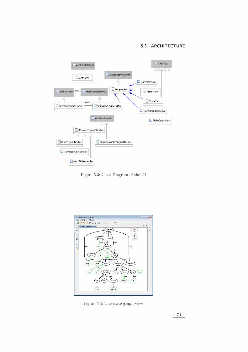
5.3. ARCHITECTURE
Figure 5.3: Class Diagram of the UI
Figure 5.4: The state graph view
71

CHAPTER 5. SEMANTIC ENGINE: TOOL FOR THE SEMANTIC
LANGUAGE
Figure 5.5: The transition stack view
The MatchingView visualizes the proof for a transition, the RulesViewshows a list of rules and the TransitionStack view shows the sequence oftransitions during simulation (see figure 5.5). The state is visualized as a graphin the StateGraphView, the Graphviz library is used to visualize the state(see figure 5.4). Figure 5.6 shows a overview screenshot and the decompositionof the perspective into different views.
Figure 5.6: The views in the user interface
User events (occur when a user clicks a menu-item or toolbar-item) are handled
72

5.4. QUALITY ATTRIBUTES
by subclasses of AbstractHandler. The AbstractEngineHandler class isa convenience class that has some useful methods for accessing the semanticengine.The user interface has one editor, the SemanticEngineEditor. Multiple ed-itors can be opened. Each editor relates to one SemanticEngine, which isencapsulated by an SemanticEngineInput object. The editor consists of mul-tiple pages (that is why it is a subclass of MultiPageEditorPart), one pageshows the current DSL, one page the current model and another page the currentSemLang specification. Note that the data in the editor cannot be changed.
5.4 Quality attributes
This section discusses the quality attributes of the tool briefly. Quality attributescan be categorized in two parts, runtime quality attributes and non-runtimequality attributes. Most quality attributes that are discussed here are not mea-sured by any means, mainly because the tool is a proof of concept. However,this section gives some insight into the quality aspects of the tool.Runtime quality attributes can be measured when the tool is executed. It con-sists of sub qualities like performance, functionality and usability. The perfor-mance of the tool was not of high priority and there are several optimizationspossible that decreases the memory usage of the tool and increases it perfor-mance. However, to get some insight into the performance of the tool a smallperformance test was performed. In this test we simulated several models of dif-ferent modelling languages. During this simulation the number of states s wascounted and the total elapsed time t was measured. These two numbers couldbe used to calculate the average time per state transition (t/(s−1)). The resultsare in table 5.1. To perform these tests one has to open the referred model file,language metamodel file and semantic description in the tool. See the disc formore info (appendix A)
Table 5.1: Performance measuresModel File Language #States Time Time / State
Factorial.ad Activity Diagram 46 56.84 s 1.24 sRecursiveFactorial.pkf Plotkin Functional 94 74.66 s 0.79 sTest1.pkf Plotkin Functional 23 18.43 s 0.80 sFibImperative.pim Plotkin Imperative 50 38.42 s 0.77 s
The state transition takes a considerable amount of time because it also includesthe visualization of the state. The visualization of the state involves applyinga graph layout algorithm and a rendering process performed by Graphviz. Thelayout algorithm used is the one introduced by Sugiyama et al [Sug] and has atime complexity of O(n). The transition algorithm itself uses the copy algorithmas explained in section . The copy algorithm itself is basically a breath-first-search algorithm and has therefore a worst case time complexity of O(n + e)where n is the number of nodes and e is the number of edges in the graphs. The
73

CHAPTER 5. SEMANTIC ENGINE: TOOL FOR THE SEMANTIC
LANGUAGE
time complexity of a single transition is not investigated, this is seen as futurework.The requirements of the tool ensured that the tool had some basic functionality.The functionality of the tool is therefore sufficient, however more functions canbe added in the future. Again we remind you that this tool is a proof of concept.The usability of the tool is probably rather good because the tool is built uponthe Eclipse framework and because we use Graphviz [gra] for state visualization.State visualization greatly increases the usability.The non-runtime qualities deal with qualities that can be measured when thesystem does not execute. These qualities include modifiability, portability andtestability. The modifiability of the tool is of course hard to measure. Thetool has extensive JavaDoc documentation and this chapter gives a high leveloverview of the software. Therefore we ensured good modifiability.The portability of the tool to other MDE frameworks is rather low; the tool istightly bound to the EMF [EMF] framework and does not provide a frameworkabstraction layer. However, with model transformations one can transform amodel to an EMF based model and still apply our approach.There are no unit-tests or other explicit tests added to the source code. Thetests were mainly performed by simulating a model and checking the output.It is difficult and time intensive to write unit tests as you have to check that anew state is exactly what is expected. Manual tests are easier because one canuse the state view to check whether a new state is correct.
5.5 Conclusion
An implementation of the Semantic Language was needed in order to show aproof of concept. A tool was build to provide simulation and debugging func-tionality. This chapter explained the requirements of the tool. A high level ar-chitecture of both the Semantic Engine and the User Interface was given inorder to understand the composition of the software.The software architecture follows good practices in software engineering; de-sign patterns are used and explained intensively. Object oriented code practiceslike encapsulation, abstraction, modularity and inheritance are heavily used.The clear separation between User Interface and Semantic Engine ensures highcohesion but low coupling.The quality attributes of the tool are also briefly discussed in this chapter.A better measurement of those attributes is desirable. However, some criticalremarks regarding the quality attributes are made. The tool is mainly a proofof concept and therefore there was no focus on runtime quality attributes.
74

6Evaluation
6.1 Introduction
This chapter gives an evaluation of our approach and compares it to existingapproaches. Firstly we cover the expressiveness of our approach; can SemLangbe used to define the semantics for any DSL? Secondly we compare our approachto existing approaches which were covered in chapter 2.7. The advantages anddisadvantages of the approaches are discussed.
6.2 Expressiveness
The expressiveness of a semantic framework in MDE says something about thepower of that framework. A semantic framework is fully expressive if the seman-tics of any DSL can be described using that framework. A limited expressivesemantic framework is a framework which can only be used for a small set ofDSLs. It is of course difficult to measure the expressiveness of a frameworkbecause there are an infinite number of DSLs.However, insight into the expressiveness of an approach can be gathered bymeans of a set of different DSLs. In chapter 3 we introduced different DSLs andextended SemLang with features which were needed to specify the semanticsof each DSL. In the end of that chapter we added features to SemLang whichmakes SemLang useful for graph based DSLs like Activity Diagrams and PetriNets.Using these example DSLs we showed that SemLang is capable of definingthe semantics for a broad range of DSLs. However, this does not prove thatSemLang can be used for any DSL. In fact it is easy to create a DSL forwhich it is difficult to define the semantics using SemLang. Such a DSL is forexample the Production System language defined by Rivera et al [RGdLV08].The semantics for that language are defined using graph transformations andMaude in the same paper for comparison purposes.We tried to use SemLang to define the semantics of the Production Systemlanguage. However, this was not a straightforward process because SemLangcannot be easily used to define the semantics of that language. SemLang rulescannot contain complex graph patterns; they can only match one object andthe direct neighbours of that object. The semantics of the Production Systemrequires complex object matching.We can conclude that SemLang is less expressive than graph transformations
75
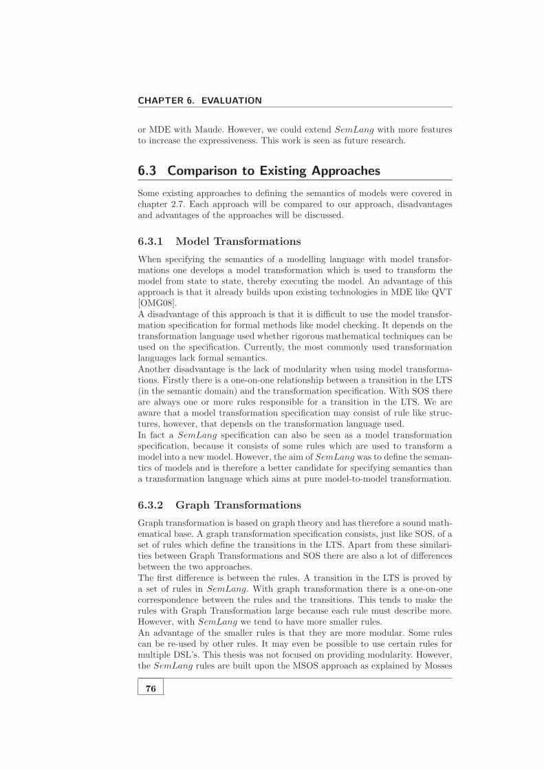
CHAPTER 6. EVALUATION
or MDE with Maude. However, we could extend SemLang with more featuresto increase the expressiveness. This work is seen as future research.
6.3 Comparison to Existing Approaches
Some existing approaches to defining the semantics of models were covered inchapter 2.7. Each approach will be compared to our approach, disadvantagesand advantages of the approaches will be discussed.
6.3.1 Model Transformations
When specifying the semantics of a modelling language with model transfor-mations one develops a model transformation which is used to transform themodel from state to state, thereby executing the model. An advantage of thisapproach is that it already builds upon existing technologies in MDE like QVT[OMG08].A disadvantage of this approach is that it is difficult to use the model transfor-mation specification for formal methods like model checking. It depends on thetransformation language used whether rigorous mathematical techniques can beused on the specification. Currently, the most commonly used transformationlanguages lack formal semantics.Another disadvantage is the lack of modularity when using model transforma-tions. Firstly there is a one-on-one relationship between a transition in the LTS(in the semantic domain) and the transformation specification. With SOS thereare always one or more rules responsible for a transition in the LTS. We areaware that a model transformation specification may consist of rule like struc-tures, however, that depends on the transformation language used.In fact a SemLang specification can also be seen as a model transformationspecification, because it consists of some rules which are used to transform amodel into a new model. However, the aim of SemLang was to define the seman-tics of models and is therefore a better candidate for specifying semantics thana transformation language which aims at pure model-to-model transformation.
6.3.2 Graph Transformations
Graph transformation is based on graph theory and has therefore a sound math-ematical base. A graph transformation specification consists, just like SOS, of aset of rules which define the transitions in the LTS. Apart from these similari-ties between Graph Transformations and SOS there are also a lot of differencesbetween the two approaches.The first difference is between the rules. A transition in the LTS is proved bya set of rules in SemLang. With graph transformation there is a one-on-onecorrespondence between the rules and the transitions. This tends to make therules with Graph Transformation large because each rule must describe more.However, with SemLang we tend to have more smaller rules.An advantage of the smaller rules is that they are more modular. Some rulescan be re-used by other rules. It may even be possible to use certain rules formultiple DSL’s. This thesis was not focused on providing modularity. However,the SemLang rules are built upon the MSOS approach as explained by Mosses
76

6.3. COMPARISON TO EXISTING APPROACHES
[Mos99, Mos02, Mos04]. MSOS is an extended version of SOS with features thataccommodate modularity.
Another advantage of SemLang is that there is a guiding principle for creatingthe rule. The guiding principle is basically: each structure should have one ormore rules; there should be a transition condition for each sub-structure of thatstructure. This guiding principle is derived from linguistics: the semantics of aphrase is a composition of the semantics of the sub-phrases. We are not awareof any guiding principle for creating rules for graph transformations.
A related advantage is that SOS is related to the interpreter design pattern[GHJV00]. When designing an interpreter one creates an interpret function foreach language structure. This is similar to the approach in SOS where eachstructure has one or more rules.
Maybe one of the most important disadvantages of graph transformation isits performance: rule matching is NP-complete. In SOS rule matching is easybecause there is always a current node that has to be matched.
With graph transformations one is required to transform a model to a type graphbefore graph transformation can be used. SemLang, however, works directlywith the metamodel. This can be seen as an advantage because the intermediatetransformation to a type graph is not needed. However, this introduces highcoupling between the metamodel and the semantic specification.
Graph transformations also has advantages over SemLang. It is very expres-sive and it has a sound theoretic basis. The biggest advantage is the graphawareness. SOS has difficulties when it is used with graphs, with SemLang weprovide a partial solution. But this solution is not as expressive as the graphtransformation approach. The comparison is summarized in table 6.1.
Table 6.1: Comparison of SemLang and Graph Transformations
Feature Graph Transformations SemLang
Rules Single rule for a transition Multiple rules for a transitionModularity May be problematic MSOS aimed at modularityGuiding Principle No guiding principle to create rules Based on principle of compositionInterpreter Not easy to map to interpreters Related to interpreter design pattern
Complexity Rule matching hard: NP-complete Rule matching easyConversion Needs conversion to type graph Works directly with the metamodelTheory Sound theoretic basis Theoretic basis work in progressExpressiveness Expressive Limited (future research)Graph awareness Good Locally tree oriented
6.3.3 MDE with Maude
Maude is a very powerful rewriting engine and MDE with Maude seems there-fore a fruitful approach. The biggest disadvantage of Maude is that it has itsown model framework. It is therefore required that models and metamodels aretransformed to Maude objects.
77
CHAPTER 6. EVALUATION
Another possible disadvantage of Maude is its complexity. It is required to learnMaude before one tries to specify the semantics of a modelling language. How-ever, the team that uses MDE with Maude is currently working on better toolintegration which will increase the usability.
6.3.4 Simulation in the Topcased Toolkit
The Topcased [CCG+08, VPF+06] approach is pragmatic and very efficientin terms of memory usage and runtime. However, the semantics is defined inthe Java programming language which makes it less useful for applying rigorousmathematical techniques. Also the code that specifies the semantics is very hardto reuse for any other modelling language.
6.3.5 Semantics Anchoring
Some general disadvantages of Semantic Anchoring were already covered insection 2.7.6. However, no comparison with SemLang was made.Again, a disadvantage of this approach is that it does not work directly with themetamodel of the DSL for which the semantics is defined. In fact this approachneeds an additional minimal modelling language for which the semantics isformally defined. A model of a DSL is then transformed to a model of thisminimal modelling language.
6.4 Conclusion
This chapter provided an evaluation of the SemLang language. The first con-clusion that can be made is that the expressiveness of SemLang has its limits.It can be extended by adding more features. However, research is needed to findout which features are needed.Another conclusion is that SemLang has several advantages over the other se-mantic approaches. SemLang is based on SOS and has therefore a good mathe-matical basis. The close coupling between the DSL metamodel and a SemLangspecification is, in our eyes, a advantage because this coupling is unavoidableand even desirable. This close coupling also prevents to use of any intermediatelanguage like we see with most other approaches.Apart from having a theoretical basis, SemLang is also pragmatical. There isa guidance for creating the rules and the rules are generally small. However, weunderstand that knowledge of SOS and its compositional aspect is needed inorder to define the semantics of a DSL.
78

7Conclusions
7.1 Introduction
This last chapter concludes the thesis. The first section gives a summary of thethesis. The next section gives an answer to the main research question and allsub-questions. The last section discusses possible directions for future research.
7.2 Summary
A lot of research is done in the Model Driven Engineering (MDE) community.However, the focus is mostly on the static aspects of MDE. MDE is often usedfor defining Domain Specific Languages (DSLs). However, the specification of aDSL also requires that the semantics of the DSL are described in some (formal)way.A semantic approach that seems suitable for defining the semantics of a DSL isStructural Operational Semantics (SOS) [Plo81]. SOS is a semantic frameworkin which the semantic domain is a Labelled Transition System (LTS). The se-mantics of a language is described using a set of rules. A single transition in theLTS can be proven by a so called upwardly-branching-tree which is built usingthe rules. However, there are several problems with applying SOS directly on aDSL. Therefore the main research question of this thesis is: Can SOS be adaptedand applied successfully on MDE?.Some other approaches for defining the semantics of modelling languages al-ready existed. In all of these approaches there is a mapping from the modellinglanguage to a semantic domain. This mapping is specified in different ways.Some approaches are very formal while other approaches are more pragmatical.None of these approaches use SOS as a framework for specifying semantics.Chapter 3 proposes some changes to SOS in order to make it applicable inan MDE context. We propose a new language for defining semantics, calledSemLang, and is itself specified as a DSL. SemLang is used to define thesemantics for some DSLs which are similar to the languages in the paper byPlotkin [Plo81]. However, SemLang also supports the specification of the se-mantics of certain graph-based languages. This is an extension to the Plotkinstyle SOS, as it only supports tree-based states.Chapter 4 provides a formal basis for SemLang based on formalizations of SOS[AFV01, MRG07, Mos04]. The semantic domain of SemLang is a labelled ter-minal transition system (LTTS) in which the states are extended models of the
79

CHAPTER 7. CONCLUSIONS
DSL. SemLang models are essentially Transition System Specifications (TSSs)in which there is a mapping from a SemLang model to a LTTS (the semanticdomain). The transitions in the LTTS can be proven by the construction ofproof trees. The main difference between SOS and SemLang is that the termsin a rule have a different task. They either match or construct model objects.The chapter does not formalize all constructs and features of SemLang. Theformalization is kept to the essential parts to keep it understandable. The maingoal of the formalization is to give a formal basis for SemLang. The focus ofthis thesis is on the pragmatical aspects of SemLang.A tool capable of executing SemLang specifications is discussed in chapter 5. Itprovides simulation and debugging functionality. The requirements of the tooland a high level architecture are both explained. The tool consists of two looselycoupled modules, the Semantic Engine and the User Interface. The SemanticEngine is an implementation of the Semantic Language and a simulation frame-work. The User Interface is a layer on top of the Semantic Engine. It providesa graphical user interface which increases the usability of the tool.Our approach is evaluated in chapter 6. SemLang is applied to several DSLs todemonstrate its expressiveness. However, the expressiveness of SemLang has itslimits. It could, for example, not be applied to the Production System languagedefined by Rivera et al [RGdLV08]. The expressiveness can be increased byadding new features to SemLang. Our approach is also compared to the otherapproaches to specifying the semantics of modelling languages (as discussed insection 2.7). SemLang is based on SOS and had therefore a good mathematicalbasis and is also relatively more pragmatical.
7.3 Answers to the Research Questions
The main problem that needed to be solved was the incompatibility betweenMDE and SOS. Initially it was not clear how SOS could be adapted to makeit useful for defining the semantics of DSLs. The main research question of thethesis was therefore:
Can SOS be adapted and applied successfully to MDE?
The answer to the main research question is that SOS in fact can be adaptedto make it useful for defining the semantics of DSLs. The research question wasdivided into different sub-questions, which are listed and answered below.
MDE models are graph structures but SOS is based on trees. Can SOS be adaptedin order to make it suitable for using it with graph structures?
The problem with graphs is that it introduces loops in the model. These loopsmay cause infinity copying of nodes. This was solved by introducing a copyalgorithm which makes sure that nodes are not copied twice. The copy algorithmis basically a breath-first-search based copy algorithm for graphs.Another feature that was added to deal with this problem is the use of referencemeta-variables. The copy algorithm deals with those variables differently. Thisfeature is not strictly needed but it increases the expressiveness of SemLang.Another feature that was added is support for quantification over lists. Both ex-istential and universal quantification is supported. This feature makes SemLangmore useful for defining the semantics of graph based languages.
SOS is based on the abstract syntax description of languages, how can SOS be
80
7.3. ANSWERS TO THE RESEARCH QUESTIONS
adapted to deal with metamodels?
This question was not difficult to answer because metamodels and abstractsyntax descriptions have a lot in common. The rules were changed in order tomatch and create objects instead of AST nodes. So called terms are used tomatch objects and create them.
Terms in rules The terms in the rules are changed. In SOS they consist ofphrases of the DSL. However, a DSL in MDE does not require the syntaxto be defined. The main elements of an MDE model are objects insteadof sentences. The terms are changed to object patterns in order to matchobjects in a model, or construct new objects.
The use of the metamodel instead of the abstract syntax description actuallyenhances SOS because it supports polymorphism; rules can be created whichmatch abstract classes.
The semantic domain of SOS is a labelled transition system in which the statesare trees. How can we change the semantic domain in order to make it suitablefor models?
In chapter 4 we choose for terminal labelled transition systems (LTTSs) as thesemantic domain for SemLang. The states in the semantic domain of SOS aresentences of the abstract syntax of the DSL and therefore always tree structures.The states in the semantic domain SemLang, however, are extended models.These extended models can be represented as graph structures. This solves theincompatibility.The answer to the main research question is that SOS can indeed by appliedto MDE, this is shown by proof of concept and partial formalization. The proofof concept consists of the SemLang language and a tool which can simulatemodels using a SemLang specification. The tool was written using the EclipseEMF [EMF] and RCP frameworks [RCP]. The architecture documentation canbe read in chapter 5. The complete source-code can be found on the disc thatcomes with this thesis (seen appendix A).
7.3.1 Limitations
There are a number of limitations that can be found in our approach. However,some limitations can be overcome and can therefore be seen as future work. Alist of limitations is given below.
• Expressiveness is limited
As explained in chapter 6 the expressiveness of SemLang is limited. Thiscan be increased by adding new features to the language. But it is notknow which features must be added and how many; too many featureswould make SemLang complex and impractical.
• The language and tool is highly coupled to the Eclipse Modelling Frame-work
It is difficult to create a modelling language without choosing one MDEapproach. However, by choosing the EMF [EMF] framework we could onlyuse SemLang to define the semantics of modelling language created withEMF. The tool itself is also highly coupled to the EMF framework.
81

CHAPTER 7. CONCLUSIONS
• Modularity is an open issue
Defining semantics of languages in a cross language modular fashion couldenable reuse between different languages. SemLang however has no func-tionality to deal with this kind of modularity. A SemLang specification isalways a single file and no other specifications can be included.
• No good insight into the efficiency and performance quality attributes
The quality attributes of the tool were explained in chapter 5. The per-formance of the tool was only roughly measured. The measurements didnot take the effect of the visualisation into account. The layout and visu-alization of the model is done in each transition and is therefore a majorcontributor to the runtime.
7.4 Future Work
This thesis provides an initial language based on SOS which can be used todefine the semantics of a DSL. The SemLang language is a proof of conceptand the tool is created to simulate models.However, there are still open issues and future research directions. A list ofpossible future research directions is given in this section. First some possibleextensions to SemLang are given. Secondly we look at some possible applica-tions fields for SemLang.
7.4.1 Concurrency & Interactivity
SOS is really powerful in specifying the semantics for concurrent systems [AFV01,MRG07]. The Semlang language does not support concurrency and synchro-nization constructs. This can be achieved by introducing labels in the LTTS ofthe semantic domain.The labels can also be used to support interactivity (as encountered in user-interface applications). The labels represent events that occur in the user inter-face. Together with this extension SemLang can be used to define the behaviourof user interfaces.
7.4.2 Rule Extensions
The current rules in SemLang consist of terms which either match or cre-ate objects. More constructs can be added to increase the expressive power ofSemLang.One way to improve the expressive power of SemLang is to add more listmatching techniques. A good candidate extension can be found in the paper ofIgarashi et al [IPW01]. In their paper they introduce a language FeatherweightJava, which is a subset of Java. Special list matching techniques are used in therules in the SOS specification of Featherweight Java.SemLang already has support for simple object expressions similar like thosefound in OCL. However, a possible extension is to adopt OCL [OMG03b] asan expression language in SemLang. OCL could be used to extend the ob-ject matching and object creation capabilities by using OCL path expressions.
82

7.4. FUTURE WORK
OCL was currently not used because it does not allow binding objects to meta-variables, therefore decreasing the object matching power of SemLang.
7.4.3 Potential Applications
There are a number of potential applications for SemLang. These applicationdomains are similar to the application domains of SOS. A limited list of appli-cations is listed below.
Simulation
The SemLang semantics of a DSL can be used to simulate models of that DSL.The purpose of simulation is to gain understanding of a system without manip-ulating the real system. Therefore simulation is always performed on a modelof the system. This is how Combemale et al [CCG+08] define simulation. Theyalso subdivide simulation in three steps: Workload generation (trace building),Model execution and Result analysis. It is possible to combine two of these steps,or even three of them.Simulation is, in fact, already supported by the tool written for this research.The tool allows simulating a model for which the semantics is defined. Theworkload (execution trace) is generated on the fly; the user can choose a transi-tion for any non-deterministic step. The result is also generated on the fly; thestates can be inspected and the proof for the transitions can also be inspectedwhile simulating the model. However, the tool is only a proof of concept. Thetool could be integrated with other tools. The usability could be improved, forexample by adding a SemLang editor.
Proofs and Reasoning
The semantic domain of SemLang is formally specified in chapter 4. A bigadvantage of a well known semantic domain is that rigorous mathematical tech-niques can be used. In SOS, for example, one can use Structural Induction (SI)to prove certain statements over a program or over the SOS rules themselves.SI fits SOS particularly well because the states in SOS are always trees; this isbecause SI is a recursive method which works well on recursively defined struc-tures like lists and trees. In order to make SI useful for SemLang one mustdefine the states of SemLang in a recursive manner. A possible solution to thisproblem is to use induction over the size of the graph. This work is seen asfuture research.
Generation of Interpreters
Interpreters (and compilers) must follow the semantics of a language. An inter-preter has a bug if it does not follow the behaviour as specified in the (formal)semantics. It looks promising to generate interpreters from the semantics specifi-cation of a language. In this way bugs can be avoided and the time to implementan interpreter can be decreased dramatically. In fact this topic is investigatedby different researchers [Mic93, Poe94, Bru99].SOS is a good candidate for generating interpreters because it is related to theInterpreter Design Pattern [GHJV00, pages 243–255]. In the Interpreter DesignPattern an Interpret operation is specified for each abstract syntax class. The
83

CHAPTER 7. CONCLUSIONS
code in an InterpretX operation for an abstract syntax structure X defines thesemantics for that structure. An Interpret operation may call other Interpretoperations in order the interpret the sub-sentences. This technique is similar tothe way the rules in SOS are specified; a rule is defined for each metaclass anda transition condition is added for each sub-structure.
84

References
[AFV01] Luca Aceto, Willem Jan (Wan) Fokkink, and Chris Verhoef. Struc-tural operational semantics. In Jan A. Bergstra, Alban Ponse, andScott A. Smolka, editors, Handbook of Process Algebra, Chapter 3,pages 197–292. Elsevier Science, Dordrecht, The Netherlands, 2001.
[B04] Jean Bezivin. In search of a basic principle for model-driven engi-neering. CEPIS, UPGRADE, The European Journal for the Infor-matics Professional V 2, pages 21–24, 2004.
[BH02] Luciano Baresi and Reiko Heckel. Tutorial introduction to graphtransformation: A software engineering perspective. In Proc. GraphTransformation - First International Conf., Barcelona, Spain, 2002.
[BHJ+05] Jean Bezivin Guillaume Hillairet, Frederic Jouault, Ivan Kurtev,and William Piers. Bridging the ms/dsl tools and the eclipse mod-eling framework. Proceedings of the International Workshop onSoftware Factories at OOPSLA, San Diego, 2005.
[Bru99] Kim B. Bruce. Formal semantics and interpreters in a principles ofprogramming languages course. In Daniel Joyce, editor, Proceedingsof the Thirtieth SIGCSE Technical Symposium on Computer Sci-ence Education, volume 31.1 of SIGCSE Bulletin, pages 331–335,N. Y., March 24–28 1999. ACM Press.
[CCG+08] Benoıt Combemale, Xavier Cregut, Jean-Pierre Giacometti, PierreMichel, and Marc Pantel. Introducing simulation and model ani-mation in the MDE topcased toolkit, 2008.
[CSAJ05] Kai Chen, Janos Sztipanovits, Sherif Abdelwalhed, and Ethan Jack-son. Semantic anchoring with model transformations. SpringerLNCS, 2005.
[ECO] Eclipse Ecore. http://www.eclipse.org/modeling/emf/.
[EMF] Eclipse Modeling Framework (EMF). http://www.eclipse.org/
modeling/emf.
[GHJV00] Gamma, Helm, Johnson, and Vlissides. Design Patterns Ele-ments of Reusable Object-Oriented Software. Addison-Wesley, Mas-sachusetts, 2000.
[GME] Generic Modeling Environment (GME). http://www.isis.
vanderbilt.edu/Projects/gme.
[GMF] Eclipse Graphical Modeling Framework (GMF). http://www.
eclipse.org/gmf.
[gra] Graphviz - Graph Visualization Software. http://www.graphviz.
org/.
[GRe] Graph Rewriting and Transformation (GReAT). http://www.
isis.vanderbilt.edu/Projects/mobies.
85

REFERENCES
[GSCK04] J. Greenfield, K. Short, S. Cook, and S. Kent. Software Factories.Wiley, 2004.
[Hec06] Reiko Heckel. Graph transformation in a nutshell. Electr. NotesTheor. Comput. Sci, 148(1):187–198, 2006.
[Hen90] Matthew Hennessy. The Semantics of Programming Languages: AnElementary Introduction Using Structural Operational Semantics.Wiley, University of Sussex, United Kingdom, 1990.
[Hoa69] Hoare. An axiomatic basis for computer programming. CACM:Communications of the ACM, 12, 1969.
[HR04] David Harel and Bernhard Rumpe. Meaningful modeling: What’sthe semantic of “semantics”? Springer LNCS, 2004.
[Hud98] Paul Hudak. Modular domain specific languages and tools. InP. Devanbu and J. Poulin, editors, Proceedings: Fifth InternationalConference on Software Reuse, pages 134–142. IEEE Computer So-ciety Press, 1998.
[IPW01] Atsushi Igarashi, Benjamin Pierce, and Philip Wadler. Feather-weight Java: A minimal core calculus for Java and GJ. TOPLAS,23(3):396–459, May 2001.
[JB06] Frederic Jouault and Jean Bezivin. Km3: a dsl for metamodel spec-ification. Proceedings of 8th IFIP International Conference on For-mal Methods for Open Object-Based Distributed Systems (LNCS4037), pages 171–185, 2006.
[JBK06] Frederic Jouault, Jean Bezivin, and Ivan Kurtev. Tcs: a dsl forthe specification of textual concrete syntaxes in model engineer-ing. Proceedings of the fifth international conference on Generativeprogramming and Component Engineering, 2006.
[JFa] JFace. http://wiki.eclipse.org/index.php/JFace.
[Ken02] Stuart Kent. Model driven engineering. Proceedings ofACME/IEEE 9th International Conference on Model Driven En-gineering Languages and Systems (Modules/UML ’06), pages 286–298, 2002.
[KT08] Steven Kelly and Juha-Pekka Tolvanen. Domain-Specific Modeling,Enabling Full Code Generation. John Wiley & Sons, Inc., 2008.
[Kur05] Ivan Kurtev. Adaptability of Model Transformations. University ofTwente, Netherlands, 2005.
[MHS05] Mernik, Heering, and Sloane. When and how to develop domain-specific languages. CSURV: Computing Surveys, 37, 2005.
[Mic93] Greg Michaelson. Interpreter Prototypes from Formal LanguageDefinitions. PhD thesis, Heriot-Watt University, Department ofComputing & Electrical Engineering, Riccarton, Scotland, EH144AS, 1993.
86

REFERENCES
[Mil90] Robin Milner. Operational and algebraic semantics of concurrentprocesses. In Jan van Leeuwen, editor, Handbook of TheoreticalComputer Science, pages 1201–1242. MIT Press/Elsevier, 1990.
[Mos99] Peter D. Mosses. Foundations of modular sos. Technical report,University of Aarhus, Denmark, 1999.
[Mos02] Peter D. Mosses. Pragmatics of Modular SOS. Springer LNCS Vol2422, University of Aarhus, Denmark, 2002.
[Mos04] Peter D. Mosses. Modular structural operational semantics. Journalof Logic and Algebraic Programming 60-61, pages 195–228, 2004.
[Mos06] Peter D. Mosses. Formal semantics of programming languages, anoverview. Electronic Notes in Theoretical Computer Science 148,pages 41–73, 2006.
[MRG07] MohammadReza Mousavi, Michel A. Reniers, and Jan Friso Groote.Sos formats and meta-theory: 20 years after. TCS: Theoretical Com-puter Science, 373(3):238 – 272, 2007. Structural Operational Se-mantics.
[OMG] OMG. Unified Modeling LanguageTM(UML R©). http://www.omg.
org/technology/documents/modeling_spec_catalog.htm#UML.
[OMG02] OMG. Meta object facility (mof) specification, version 1.4. OMGDocument, 2002.
[OMG03a] OMG. Meta object facility (mof) 2.0 core specication. OMG Doc-ument, 2003.
[OMG03b] OMG. Uml ocl 2.0 specification. OMG Document, 2003.
[OMG08] OMG. Meta Object Facility (MOF) 2.0, Query/View/Transfor-mation specification, V1.0. http://www.omg.org/docs/formal/
08-04-03.pdf, 2008.
[Plo81] Gordon D. Plotkin. A structural approach to operational semantics.Technical report, University of Aarhus, Denmark, 1981.
[Poe94] A. Poetzsch-Heffter. Developing efficient interpreters based on for-mal language specifications. In P. Fritzson, editor, Compiler Con-struction, volume 786 of LNCS, pages 233–247. Springer, 1994.
[RCP] Eclipse Rich Client Platform (RCP). http://wiki.eclipse.org/index.php/Rich_Client_Platform.
[RGdLV08] Jose Eduardo Rivera, Esther Guerra, Juan de Lara, and AntonioVallecillo. Analyzing rule-based behavioral semantics of visual mod-eling languages with maude. In Dragan Gasevic, Ralf Lammel, andEric Van Wyk, editors, SLE, volume 5452 of Lecture Notes in Com-puter Science, pages 54–73. Springer, 2008.
[RRDV07] R. Romero, J.E. Rivera, F. Duran, and A. Vallecillo. Formal andtool support for model driven engineering with maude. Journal ofObject Technology, 2007.
87

REFERENCES
[RV07] J.E. Rivera and A. Vallecillo. Adding behavioral semantics to mod-els. Proceedings of the 11th IEEE International Enterprise Dis-tributed Object Computing Conference, 2007.
[Sch86] David A. Schmidt. Denotational Semantics – A Methodology forLanguage Development. Wm. C. Brown Publishers, 1986.
[SF07] Markus Scheidgen and Joachim Fischer. Human comprehensibleand machine processable specifications of operational semantics.ECMADA-FA, LNCS 4530, 2007.
[Sol00] R. Soley. Model driven architecture. OMG Document, 2000.
[SS71] Dana Scott and Christopher Strachey. Toward a mathematical se-mantics for computer languages. pages 19–46. April 1971.
[Sug]
[SW08] Daniel A. Sadiley and Huido Wachmuth. Prototyping visual in-terpreters and debuggers for domain-specific modeling languages.ECMADA-FA, LNCS 5095, 2008.
[SWT] SWT: The Standard Widget Toolkit. http://www.eclipse.org/
swt.
[TCCG07] Xavier Thirioux, Benoıt Combemale, Xavier Cregut, and Pierre-Lo”ic Garoche. A framework to formalise the mde foundations. In-ternational Workshop on Towers of Models (TOWERS), 2007.
[vDKV00] Arie van Deursen, Paul Klint, and Joost Visser. Domain specificlanguages: An annotated bibliography. ACM SIGPLAN Notices, V25, issue 6, pages 26–36, 2000.
[VPF+06] F. Vernadat, Christian Percebois, Patrick Farail, R. Vingerhoeds,Alain Rossignol, Jean-Pierre Talpin, and David Chemouil. TheTOPCASED project - A toolkit in OPen-source for critical appli-cations and system development. In Data Systems In Aerospace(DASIA), Berlin, Germany, page (electronic medium), http://
www.esa.int/publications, May 2006. European Space Agency(ESA Publications).
88
AAppendix A: Compact Disc
This thesis is accompanied with a compact disc that contains software, sourcecode, documentation and other files:
1. Thesis in Digital Form
Path /thesis
Description This thesis in digital pdf format. The thesis includes hyper-links that allow easy navigation between chapters.
Path /thesis/latex/
Description Contains the latex source code of the thesis
2. Presentation in Digital Form
Path /presentation/
Description Contains the presentation(s) done for this thesis in pdf form
3. Tool Binaries and Source Code
Path /tool
Description Contains the binaries of the tool for the Windows platform
Path /code/tool
Description Contains the sourcecode of the tool. Open this folder ineclipse as an eclipse workspace
Path /code/tool/SemanticLanguage
Description Contains the metamodel and concrete syntax of the seman-tic language defined in km3
Path /code/tool/SemanticEngine
Description Contains the sourcecode for the semantic engine
Path /code/tool/SemanticEnginePlugin
Description Contains the sourcecode for the user interface of the seman-tic engine
89

APPENDIX A. APPENDIX A: COMPACT DISC
4. Example DSLs and their Semantics
Path /code/dsls
Description Contains a list of DSLs for which the semantics are defined.
Path /code/dsls/*/Metamodel
Description Contains the metamodel of a dsl
Path /code/dsls/*/Samples
Description Contains one or more sample models of the dsl
Path /code/dsls/*/Semantics
Description Contains the semantics specification in the Semantic Lan-guage of the dsl
90