operations manual - equipment · ansi b11.05 1988 (r2008) ironworkers - safety requirements for...
TRANSCRIPT

Operations Manual
Original Instructions - IW5503
Serial Number:

1
1 General Declarations of Conformity
Company Profile
Warranty
Machine Identification
Operator and Supervisor Information
Signal Word Definition
Signal Word Panel
Operational Precautions
Machine Operations
Foreseeable Misuse
Machine Life Cycle
6 Operations Diagrams
10 Control Panel
11 Angle Shear Station Safe Operation
Angle Shear Operation
12 Bar Shear Station Safe Operation
Bar Shear Operation
13 Electric Stroke Control Setup
Safe Operation
Electric Stroke Control Operation
14 Punch Station Setup
Safe Operation
Punch Operation
Punch and Die Operating Clearances
Punch Capacities
Material Multiplier
Punch Tonnage Requirements (Figure 1)
16 Notcher Station (50/60/65/75/100DX/120 Ton Ironworkers)
Safe Operation
Notcher Operation
Optional Tooling17 Angle Notcher
18 Auto-Cut Tool
19 Brake
20 Notcher (25/40/55/100Ton)
22 Oversize Punch
23 Pipe Notcher
24 Rod Shear/Multi-Shear
25 241 Punch 26 Accessory Light
27 Hydraulic Accessory Package
28 Troubleshooting
Operations Manual Table of ContentsDeclarations of Conformity
EU DECLARATION OF CONFORMITY WITH COUNCIL DIRECTIVE 2006/42/ECDate of Issue: 01/11/2013
Directive:Machinery Safety Directive 2006/42/ECElectromagnetic Compatibility Directive 2004/108/EECLow Voltage Directive 2006/95/ES
Conforming Machinery: Model: 55 TonType: Hydraulic Punching MachineSerial Number: Refer to Title Page
Manufacturer: Edwards Manufacturing Company1107 Sykes StreetAlbert Lea, MN 56007, USA
Person Authorized to compile the Technical File Established in the EU
Julian Smith and Melanie Smith – DirectorsAlpha Punch & Machinery LtdUnit 7 Binder Industrial ParkEland RoadDenaby, Doncaster DN12 4HA UKTel: 011-441709866083Fax: 011-441709866356
Harmonised StandardsReferenced or Applied:
EN 13857:2008, EN ISO 13850:2008, EN 60204-1:2006+A1:2009/AC 2010, EN 12100:2010, EN 349:1993+A1:2008, EN 953:1997 +A1:2009, EN 1037:1995+A1:2008, EN 614-1:2006+A1:2009, EN ISO 4413:2010, BS EN 13849-1:2006
Specifications with which Conformity is Declared:
Essential Health and Safety Requirements of Annex 1 of the Machinery Directive
We hereby certify that the machinery described above conforms with the essential health and safety requirements of Council Directive 2006/42/EC on the approximation of the laws of the Member States relating to the safety of machinery.
Signed:
Signatory: Printed Name : Douglas L. Friend
Title: Chief Operating Officer
Technical File Reference Number SF11987A1.EMC
Notes Concerning Harmonized Standards Referenced or applied:EN ISO 13857:2008 Safety of machinery. Safety distances to prevent hazard zones being reached by upper and lower limbs.
EN ISO 13850:2007 Safety of machinery — Emergency stop — Principles for design
EN 60204-1:2006+A1:2009/AC 2010 Safety of machinery. Electrical equipment of machines. General requirements.
EN 349:1993+A1:2008 Safety of machinery. Minimum gaps to avoid crushing of parts of the human body.
EN 953:1997 +A1:2009 Safety of machinery. Guards. General requirements for the design and construction of fixed and movable guards.
EN 1037:1995+A1:2008 Safety of machinery. Prevention of unexpected start-up
EN 12100:2010 Safety of Machinery – General Principles for design – Risk Assessment and risk reduction.
EN 614-1:2006+A1:2009 Safety of machinery — Ergonomic design principles —. Part 1: Terminology and general principles.
EN ISO 4413:2010 Hydraulic fluid power - General rules and safety requirements for systems and their components
BS EN 13849-1:2006 Safety of machinery. Safety related parts of control systems. General principles for design

2 3
DECLARATION OF NOISE EMISSION Sound Pressure and Sound Levels per EN ISO 1102Date of Issue: 01/11/2013
Machinery:Model: 55 TonType: Hydraulic Punching MachineSerial Number: Refer to Title Page
Operating Idle
LpAm
(Operator Position) 84 dB (A) 43 dB (A)
LpAm
(Bystander Position) 81 dB (A) 41 dB (A)
Peak C-weighted instantaneous SPL in the Operator’s position LpCpeak
95 dB (C) ---
Sound power emitted where the equivalent continuous A-weighted SPL exceeds 80 dB (A). 8.4 Bel ---
The average difference between the extraneous noise level and the sound intensity level at each measuring point is: LpAm
Δ = 41 dB (A)
Ambient Correction Factor K3A calculated according to EN ISO 11204 Appendix A. 4 dB( A)
Measurements were made at a height of 1.5 m and 1 m from the Operator Position and all four sides of the equipment.
The figures quoted are emission levels and are not necessarily safe working levels. While there is a correlation between the emission and exposure levels this cannot be used reliably to determine whether or not further precautions are required.
Factors that influence the actual level of exposure of the workforce include characteristics of the work room, the other sources of noise, etc. such as the number of machines and other adjacent processes. Also, the permissible level of exposure can vary from country to country.
This information, however, will enable the user of the machine to make a better evaluation of the hazard and risk.
Edwards Manufacturing Company 1107 Sykes Street Albert Lea, MN 56007 USA
Company Profile
Edwards Manufacturing Company manufactures a full line of high quality,
low maintenance hydraulic ironworking machines, associated
tooling and accessories that are used in the steel fabrication industry. With proper operation, care,
and maintenance, your Edwards Ironworker or Hydraulic Accessory Tool will provide years of safe, trouble-free
service. Please take time to study this Operator’s Manual carefully to fully understand Ironworker and Hydraulic Accessory Tool safety procedures, set-up, operation, care, maintenance, troubleshooting and warranty coverage prior to putting the machine into production. Any questions not answered within this manual can be directed to your local Edwards Ironworker dealer or factory representative.
Contact the factory:
Edwards Manufacturing Company1107 Sykes StreetAlbert Lea, MN 56007507 373 8206 PHONE507 373 9433 FAXwww.edwardsironworkers.com
General Questions:[email protected]
Service Questions:[email protected]
Contact your dealer:
WarrantyEdwards Manufacturing Company will, within one (1) year of date of original purchase (proof of purchase required), replace F.O.B. the factory, any goods, excluding punches, dies and shear blades, which are defective in materials or workmanship provided that the buyer return the defective goods, freight pre-paid, to the seller, which shall be the buyer’s sole and exclusive remedy for the defective goods. Hydraulic components are subject to their manufacturer’s warranty.
Edwards Manufacturing Company will, within thirty (30) days of date of original purchase (proof of purchase required), replace F.O.B. the factory, any punches, dies and/or shear blades, which are defective in materials or workmanship.
This warranty does not apply to machines and/or components which have been altered, changed or modified in any way, or subjected to abusive and abnormal use, inadequate maintenance and lubrication, or subjected to use beyond seller recommended capacities and specifications. Edwards Manufacturing Company shall not be liable for labor costs expended on such goods or consequential damages. Edwards Manufacturing Company shall not be liable to the purchaser or any other person for loss, down-time, or damage directly or indirectly arising from the use of the goods or from any other cause. No officer, employee, or agent of Edwards Manufacturing Company is authorized to make any oral representations or warranty of fitness or to waive any of the foregoing terms and none shall be binding on Edwards Manufacturing Company.
Machine IdentificationYour Edwards Ironworker has been serialized for quality control, product traceability and warranty enforcement. Please refer to the aluminum identification tag with engraved serial number, electrical and power specifications when ordering parts or filing a warranty claim.
Declaration of Conformity with ANSI / ISO / NFPA / OSHA Standards relating to the Manufacture of Ironworking MachineryDate of Issue: 12/05/2013
Applicable Standards: ANSI / ISO / NFPA / OSHA
Conforming Machinery: Model: 55 TonType: Hydraulic Punching MachineSerial Number: Refer to Title Page
Manufacturer: Edwards Manufacturing Company1107 Sykes StreetAlbert Lea, MN 56007, USA
Harmonised StandardsReferenced or Applied:
ANSI B11.05, ANSI B11.0, ANSI B11.19, ANSI / ASSE Z244.1, ANSI Z535.2, ANSI Z535.3, ANSI Z535.4, ANSI Z535.5, ANSI / ISO 12100, ISO 13849-1, NFPA 79, OSHA1910.147, OSHA1910.212, OSHA1910.219
We hereby certify that the machinery described above conforms with the essential health and safety requirements of Council Directive 2006/42/EC on the approximation of the laws of the Member States relating to the safety of machinery.
Signed:
Signatory: Printed Name : Douglas L. Friend
Title: Chief Operating Officer
Technical File Reference Number SF11987A1.EMC
Notes Concerning Harmonized Standards Referenced or applied:ANSI B11.05 1988 (R2008) Ironworkers - Safety Requirements for Construction, Care and Use
ANSI B11.0 2010 Safety of Machinery - General requirements and Risk Assessment
ANSI B11.19 Performance Criteria for Safeguarding
ANSI / ASSE Z244.1 2003 (R2008) Control of Hazardous Energy - Lockout / Tagout and Alternate Methods
ANSI Z535.2 2011 Environmental and Facility Safety Signs
ANSI Z535.3 2011 Criteria for Safety Symbols
ANSI Z535.4 2011 Product Safety Signs and Labels
ANSI Z535.6 2011 Product Safety Information in Product Manuals, Instructions, and Other Collateral Materials
ANSI / ISO 12100 Safety of Machinery - General Principles for design - Risk Assessment and risk reduction.
ISO 13849-1 Safety of machinery. Safety related parts of control systems. General principles for design.
NFPA 79 2012 Electrical Standards for Industrial Machinery
OSHA1910.147 1989 The Control of Hazardous Energy (Lockout / Tagout)
OSHA1910.212 1971 General Requirements for all Machines
OSHA1910.219 1971 Mechanical Power Transmission Apparatus

4 5
This is one of four manuals supplied with your machine. • Installation Manual • Safety Instructions Manual • Operations Manual • Maintenance Manual
READ ALL MANUALS BEFORE OPERATING MACHINERY. Operating machinery before reading and understanding the contents of all four manuals greatly increases the risk of injury.
Each of the four machine manuals describe ‘best practices’ in handling, installing, operating and maintaining your machine. The contents of each manual is subject to change without notice due to improvements in the machinery or changes in National or International standards.
All rights reserved. Reproduction of this manual in any form, in whole or in part, is not permitted without the written consent of Edwards Manu-facturing Company.
Keep all manuals close to the machine to allow for easy reference when necessary.
Provide operators with sufficient training and education in the basic functions of the machine prior to machine operation.
Do not allow for operation of the machine by unqualified personnel. Edwards Manufacturing Company is not liable for accidents arising from unskilled, untrained operation.
Do not modify or change the machine without written authorization from Edwards Manufacturing Company. Unauthorized modification to a ma-chine may result in serious operator injury, machine damage and will void your machine warranty.
Never leave a powered machine unattended. Turn machinery OFF be-fore walking away.
This machine is manufactured for use by able bodied and able minded operators only. Never operate machinery when tired or under the influ-ence of drugs or alcohol.
Do not resell, relocate or export to a destination other than to the original point of sale. Edwards has designed this machine to meet the stan-dards of the original receiving country and is not liable for meeting any governing body or performance standards beyond those of the original receiving country.
Indicates a hazardous situation that, if not avoided, will result in death or serious injury.
Indicates a hazardous situation that, if not avoided, could result in death or serious injury.
Indicates a hazardous situation that, if not avoided, could result in mild or moderate injury.
Indicates information considered important, but not hazard related.
Signal Word Panel on Machine
Critical machine safety information is identified on signal word labels. La-bels are attached adjacent to the potentially hazardous locations of the machine. Reference the Safety Instruction Manual for additional informa-tion regarding the potentially hazardous condition identified on the label.
Review ALL labels on the machinery, reference the Safety Instruc-tions Manual, the operational precautions and the safe operations sections within this manual before any operation activity is initiated.
Failure to read and understand the signal word labels affixed to the machinery may result in operator death or injury.
Signal Word DefinitionOperator and Supervisor Information
Edwards Ironworkers are designed to punch, shear and notch mild steel plate, barstock and angle. A wide range of accessories are avail-able to fabricate rod and square stock, sheet metal and pipe. Edwards Ironworkers operate by applying hydraulic force to a moving center. The center moves within a frame in a simple, vertical path and exerts force through shear blades, punch and dies, notchers, brake dies or bump-die tooling upon A36 mild steel. Edwards Ironworkers are designed for single operator use only; unless otherwise identified with a D.O./Dual Operator designation.
The following pages detail the proper operations procedures for setting up and safely operating the standard and optional tooling of your Edwards Ironworker.
Foreseeable Misuse
Do not use this equipment for any purpose not described in this manual. Using this equipment in ways not described in this manual could result in death or serious injury to the operator.
Machine Life Cycle
Edwards Ironworkers are designed to be generally free from risk throughout their life cycle from installation to dismantling and dis-posal. Consult your local governmental agency for guidelines and pro-cedures to ensure the safe disposal and recycling of system hydrau-lics, electronics and metals.
Reasonable, common sense safety precautions should be observed when operating the Ironworker or hydraulic accessory tool. The following pre-cautions are described in order of their hazard.
Electrical Hazard Dangerous high voltages are present inside the electrical enclosure of this product. Only qualified, authorized, maintenance or service personnel should gain access to the electrical panel.
Lockout Power Danger, circuits are live. Lockout / tagout upstream power source before any maintenance activity is performed.
Shear / Crush Hazard Moving parts can cut and crush. Keep hands clear when servicing and maintaining the Ironworker.
Hydraulic Fluid Hazard Hydraulic hoses are under pressure. Pressurized fluid can pierce skin and cause severe injury. To avoid physical hazard, always wear personal protective equipment when servicing / maintaining the Ironworker.
Do Not Operate With Guard Removed Physical barriers and guards have been designed and installed to protect the operator from moving parts that can pinch, cut and crush. If it is necessary to remove guarding when servicing the Ironworker, immediately replace guards after service and prior to power being restored to the machinery.
Refer to Manuals For safe installation, operation and maintenance of the machine, read: Installation Manual Safety Instructions Manual Operations Manual Maintenance Manual
Wear Personal Protective Equipment To avoid physical hazard wear protective eyewear, clothing, gloves, footwear, head-gear and hearing protection.
Operational Precautions Machine Operations

6 7
Angle Shear Station
Control Panel
Electric Stroke Control
Punch Station
Operations Diagram • Machine Front
Grease Daily Grease Daily
Foot Pedal
Open Station
Flat Bar Shear Station
Grease Daily5 Locations
Front Cylinder Guard
Operations Diagram • Machine Back
Angle Shear StationRear Drop Off
Rear Cylinder Guard
Flat Bar Shear Rear Drop Off

8 9
Operations Diagram • Machine Right
Open Station
Rear Motor Cover
Operations Diagram • Machine Left
Punch Station
Optional Hydraulic Accessory Pack

10 11
Edwards JAWS Ironworkers feature a centrally located, integrated Con-trol Panel. Hazardous voltage is present within the control panel. The panel should only be opened and serviced by authorized personnel. An external power source enters this panel and is distributed to the vari-ous working components of the machine.
Push to StartThis button energizes the machine. When energized this recessed but-ton is internally illuminated and will glow green. If the machine does not start when pressed an emergency palm stop button may have been previously pressed and will need to be reset to allow for the start button to energize the machine.
Emergency Palm StopThis button de-energizes the machine and contains a manual, safety reset function. The projecting, red, palm stop style button is set within a safety yellow bezel and is pushed to de-energize the machinery. Once de-energized the machine requires the palm stop to be re-set prior to energizing the machine. Simply rotate the emergency palm stop button clockwise. The button will retract and the machine will be available for powered operation.
Operations ControlThis three-position switch allows the ironworker operation to shuttle be-tween Ironworker, hydraulic accessory or auto-cut mode.
IronworkerPower the Ironworker by rotating the three position switch counter-clockwise. This function allows for operations of the Ironworker only.
AccessoryPower your Edwards hydraulic accessory tools by rotating the three position switch to the vertical position. This function allows for opera-tions of Edwards hydraulic accessories only. The four, female, M12 plug connections coordinate with accessory controls when power is shifted from the Ironworker operation to Hydraulic Accessory tool operation. An additional M12 connection allows for an optional, auxiliary light.
Auto-cutPower the Auto-Cut operation by rotating the three position switch clock-wise. This function allows for operations of the Auto-Cut function only.
Lockout/TagoutThis round, safety red switch is set within a square, safety yellow housing. The switch allows for proper procedures to be followed when de-energizing, isolating, and ensuring the energy isolation of the Ironworker. The Lockout/Tagout switch is used, in conjunction with Owner safety and maintenance programs to ensure that equipment and machinery is de-energized and isolated from unexpected start-up by physically locking machinery in a state of zero energy.
To lockout the Ironworker turn the red switch counterclockwise until the black tagout bar is horizontal. Pull the black, spring-loaded tagout mechanism to install the maintenance/safety lock and tag provided by the Owner of the machinery. The machine is now de-energized and is available for authorized personnel to maintain and service the machinery.
To open the control panel for servicing, gently pull the ‘hopper-style’ hinged cover. The cover will not open fully until a safety yellow thumb slide located within the safety yellow housing is rotated clockwise. Reverse operation following service to resume Ironworking.
Control Panel Angle Shear Station
Your Ironworker may include an angle iron shear as a standard fea-ture. The angle shear will provide a distortion and burr free shear cut to mild steel angle stock as listed in the Ironworker Speci-fications as well as described on the capacity labels positioned at the Angle Shearing Station. The Angle Shearing Station on the Edwards Ironworker allows for straight cutting applications. An oversized material hold down adjusts with a simple thumb crank to safely restrain the material being cut.
Integrated angle shears are factory tuned to proper clearances and are ready to begin shearing operations. [Shear blades are wear-ing parts and will need to be maintained or replaced over time. Refer to Maintenance Manual for blade maintenance, removal and replacement.]
Safe OperationObserve the following guidelines when operating the Angle Shear Station:
• Never exceed the capacities of the machine or tooling as described in the Ironworker Specifications or listed at the tooling station.
• Check shear blade clearance at every tooling change or extended shear operation. Maintain proper operating clearance at bar shear and angle shear stations. Refer to Maintenance Manual for tol-erance adjustment instructions. Failure to maintain clearance will damage shear blades and support brackets.
• Fully engage the material hold-down with the material being cut.
• Do not stack material to cut in the shear station.
• Perform complete shear operations only – partial shear cuts may jam the drop off side of the frame and could result in breakage and operator injury.
• Do not shear angle smaller than the hold-down will accommodate.
Angle Shear Operation1. Clear shear station of any tools or debris prior to powering the
machine on.
2. Turn machine on. The shear blades will be in their neutral position. Place angle iron into the material hold-down and position your cut mark adjacent to the moving shear blade.
3. Secure the angle iron in the material hold-down by engaging the handscrew into the material.
4. Clear your hands from the working area and depress the foot pedal to activate the shear station.
5. When the cut is complete, release the foot pedal to automatically return the shear blades to their neutral position. If equipped with the hydraulic hold-down feature, the hold-down will retract when pressure on the foot pedal is released at the end of the cut cycle.
6. Reverse the thumb screw to raise the material hold-down and remove your material.

12 13
Your Ironworker may include a bar shear as a standard feature. The bar shear will provide a distortion and burr free shear cut to mild steel bar stock as listed in the Ironworker Specifications as well as described on the capacity labels positioned at the Bar Shear Station. The Bar Shear allows for straight or angled cutting operations. The material hold down adjusts with a simple hand crank to safely restrain the material being cut.
Bar shears are factory tuned to proper clearances and are ready to begin shearing operations.
Shear blades are wearing parts and will need to be maintained or replaced over time. Refer to the Maintenance Manual for blade maintenance, removal and replacement.
Safe OperationObserve the following guidelines when operating the Bar Shear Station:
• Never exceed the capacities of the machine or tooling as described in the Ironworker specifications or listed at the tooling station.
• Maintain correct operating clearance at bar shear and angle shear stations. Refer to the Maintenance Manual for tolerance adjust-ment instructions. Failure to maintain proper blade clearance will damage shear blades and shear blade support.
• Fully engage the material hold-down with the material being cut.
• Do not stack material to cut in the shear station.
• Perform complete shear operations only – partial shear cuts may jam the drop off side of the frame and could result in breakage and operator injury.
• Use shearing aids when working with small items at the shear sta-
tion.
Bar Shear Operation1. Clear bar shear station of any tools or debris prior to powering the
machine on.
2. Turn machine on. The shear blades will be in their neutral position. Place bar stock on the feed table and push the material under the material hold-down. Position your desired cut mark adjacent to the moving shear blade.
3. Secure the bar stock in the material hold-down by engaging the handscrew into the material.
4. Clear your hands from the working area and depress the foot pedal to activate the shear station.
5. When the cut is complete, release the foot pedal to automatically return the shear blades to their neutral position. Reverse the hand screw to raise the manual material hold-down and remove your material.
Bar Shear Station
Electric stroke control is standard on all Ironworker models with the exception of the 25 Ton Ironworker. Stroke control enables the Ironworker operator to shorten up and down stroke with minor adjustment of two hand screws. Utilize stroke control for precision bending with your brake tooling, when using embossing or bump dies or to simply increase production from your punch, notch or shear stations.
SetupElectric Stroke control is factory installed and arrives fully set up for immediate use.
Safe OperationObserve the following guidelines when using and adjusting the electric stroke control function.
• Read, understand and follow punching, notching and shearing tol-erances as described in related chapters of this manual.
• Never exceed the capacities of the machine or tooling as described in the Ironworker specifications or listed at the tooling station.
• Keep limit switches free of dirt and grime.
• Never remove stroke retention nuts from factory setting.
• Never reverse stroke limit switches.
• Confirm that red light is illuminated. If not illuminated, machine cyle is not complete and potential heat build-up may occur.
Electric Stroke Control Operation Set upstroke for rapid cycling of your punching, shearing and notching stations.
1. Power machine on and use the jog function of your electric foot pedal to bring tooling down to rest just above the material being worked.
2. Turn machine off.
3. Adjust upper handle with tapered collar to engage limit switch.
4. Power machine on. Tooling will stay in set position. Top limit switch will be showing a red light.
5. Remove material from tooling station and cycle machine. Tooling should return to pre-set position. Red light will be on.
6. Place material in tooling station and cycle machine.
Set downstroke for bump die operation1. Power machine on and use the jog function of your electric foot
pedal to bring ram down to engage tooling. Jog ram to push bump die tooling to the specified depth.
2. Turn machine off.
3. Adjust lower handle with tapered collar to engage limit switch.
4. Power machine on. Ram will return to top of stroke.
5. Cycle machine to insure proper stroke depth.
6. Place material in tooling station and cycle machine.
Set downstroke for brake operation1. Power machine on and use the jog function of your electric foot
pedal to bring ram down to engage tooling with material.
2. Jog ram to push brake die tooling to the specified depth / brake angle.
3. Turn machine off.
4. Adjust lower handle with tapered collar to engage limit switch.
5. Power machine on. Ram will return to top of stroke. Red light will be on.
6. Place test material in tooling station and cycle machine to insure proper stroke depth and material brake.
Electric Stroke Control

14 15
Your Ironworker is capable of punching materials as listed in the Ironworker Specifications as well as described on the capacity labels positioned adjacent to the Punch station.
Setup Your Edwards Ironworker has been shipped with a punch and die installed within the punch station. Punch and dies are wearing parts and will need to be maintained or replaced over time. Refer to the Maintenance Manual for removal and replacement instructions. When changing the punch and die during typical operation please observe the following steps.
Turn off power to machine by depressing the red stop/off button or lockout upstream power at the main electrical panel.
1. Swing Stripper Bar away by loosening 4 bolts (2 on either side of punch station) with a 3/4” wrench. After swinging Stripper Bar away, re-tighten one bolt to prevent it falling back on you.
2. Remove punch by loosening the punch nut assembly with factory supplied wrench.
3. Remove die by loosening the set screw at the side or front edge of the punch table and then lifting die from the die holder. If the die resists removal gently tap the die from the underside of the punch table to loosen the die for removal.
4. Install new die and tighten set screw. If loading a shaped die, align the whistle spot with the set screw and tighten.
5. Install new punch and tighten punch nut with wrench. If using a shaped punch, align the locating keystock of the punch with the corresponding slot within the punch stem assembly and tighten the punch nut with the wrench.
6. Check for punch and die alignment by powering up the machine and inching down the punch to meet the die with the foot pedal. Check to see that the punch is centered in the die.
7. In the event that the punch and die are not aligned, loosen the bolts under the table allowing the table to be moved to center the die. When aligned, tighten the table bolts to secure the table.
8. Loosen bolts and swing the stripper bar back in place. Adjust of stripper bar for minimal clearance between the top of the material and the bottom of the stripper.
Safe Operation
Please observe the following guidelines when operating the Punch Station:
• Follow manufacturers punch and die clearance recommendations. Follow punch tonnage requirements (Figure 1).
• Never exceed the capacities of the machine or tooling as described in the Ironworker specifications or listed at the tooling station.
• The thickness of the material you are punching should not exceed the diameter of the punch being used.
• Check punch and die alignment after every tooling change or extended punch operation.
• Adjust the punch stripper supplied with your Edwards Ironworker to allow for material positioning and material stripping.
• Do not stack material to punch in the punching station.
• Use one or two drops of oil at the punch to aid in stripping material from the punch as well as to extend the life of the punch tooling.
• Punch complete holes only – partial holes will side load the punch tooling and could result in punch breakage and operator injury.
• Use punching aids when working with small items at the punch station.
Punch Station
26 ga. (.0179) 0.18 0.27 0.36 0.45 0.54 0.63 0.72 0.81 0.90 0.99 1.07 1.16 1.25 1.34 1.4324 ga. (.0239) 0.24 0.36 0.48 0.60 0.72 0.84 0.96 1.08 1.20 1.31 1.43 1.50 1.67 1.89 1.9122 ga. (.0299) 0.30 0.45 0.60 0.75 0.90 1.05 1.20 1.35 1.50 1.65 1.80 1.95 2.10 2.24 2.3920 ga. (.0359) 0.36 0.54 0.72 0.90 1.08 1.26 1.44 1.62 1.80 1.98 2.15 2.33 2.51 2.69 2.8718 ga. (.0478) 0.48 0.72 0.96 1.20 1.43 1.67 1.91 2.15 2.39 2.63 2.87 3.11 3.34 3.58 3.8216 ga. (.0598) 0.60 0.90 1.20 1.50 1.79 2.09 2.39 2.69 2.99 3.29 3.59 3.89 4.19 4.49 4.7814 ga. (.0747) 0.75 1.12 1.49 1.87 2.24 2.61 2.99 3.36 3.73 4.11 4.48 4.86 5.23 5.60 5.9712 ga. (.1046) 1.05 1.57 2.09 2.62 3.14 3.66 4.18 4.71 5.23 5.75 6.28 6.80 7.32 7.85 8.5710 ga. (.1345) 2.02 2.69 3.36 4.04 4.71 5.38 6.05 6.73 7.40 8.07 8.74 9.42 10.09 10.763/16 (.187) 2.81 3.74 4.68 5.61 6.50 7.48 8.42 9.35 10.29 11.22 12.16 13.09 14.03 14.961/4 (.250) 5.00 6.25 7.50 8.75 10.00 11.25 12.50 13.75 15.00 16.25 17.50 18.75 20.003/8 (.375) 11.25 13.13 15.00 16.88 18.75 20.63 22.50 24.38 26.25 28.13 30.001/2 (.500) 20.00 22.50 25.00 27.50 30.00 32.50 35.00 37.50 40.005/8 (.625) 31.25 34.38 37.50 40.63 43.75 46.88 50.003/4 (.750) 45.00 48.75 52.50 56.25 60.007/8 (.875) 61.25 65.63 70.001” (1.000) 80.00
1/8 3/16 1/4 5/16 3/8 7/16 1/2 9/16 5/8 11/16 3/4 13/16 7/8 15/16 1”Stock Thickness Hole Diameter
Figure 1 - Punch Tonnage Requirements
Punch Operation1. Clear the punch station of any tools or debris prior to powering the
machine on.
2. Place the material to be punched between the punch and die. Check to see that your material is spanning the stripper plate and that adequate material is available to safely position the material.
3. Clear your hands from the working area and depress the foot pedal to move the punch through the material and into the die.
4. When the punch is complete, release the foot pedal to automati-cally strip the material from the punch and return the punch to its neutral position.
Punch and Die Operating Clearances Maintain the following clearance between punch and die.
Material Thickness Total Clearance 16 gauge and lighter .006” 15 gauge - 13 gauge .010” 3/32” - 5/32” 1/64” 3/16” - 15/32” 1/32” 1/2” - 23/32” 1/16” 3/4” and heavier 3/32”
Punching CapacitiesYou can determine the tonnage required to punch A36 mild steel (yield strength 36,300 psi, 65,000 psi tensile) by applying the following for-mulas for round or shaped holes. For materials other than mild steel please refer to the multiplier table.
Round Holes Punch Dia. x Material Thickness x 80 = Tons of pressure required
Example: How many tons of force do I need to punch a 3/8” hole in 1/4” mild steel?
.375 x .25 x 80 = 7.5 tons
Punch Tonnage Requirement (Figure 1)
Shaped Holes
1/3 Punch Perimeter x Material thickness x 80 = Tons of pressure required Example: How much force do I need to punch a 3/8” x 1” rectangular hole in 1/4” mild steel?
(.33 x 2.75) x .25 x 80 = 18.1 tons
Material MultiplierWhen punching materials other than mild steel first calculate tonnage as shown above then apply the multiplier for the listed material.
Aluminum(2024-0) 0.36 Brass (1/4 hard) 0.70 Copper (1/2 hard) 0.52 Steel (50% carbon) 1.60 Steel (cold rolled) (1018) 1.24 Stainless Steel (303) 1.50

Figure A
Incorrect use - material supported on one blade
Figure B
Correct use - material supported by two blades
Figure C
Correct use - material supported by three blades
16 17
Your Ironworker includes a Notcher tool as a standard, integrat-ed feature. Notcher tooling includes one moving, three sided top notcher blade and three, four sided bottom blades set into a base table assembly. Notcher tooling creates a two or three sided shear cut in mild steel by passing the top notcher blade through the bot-tom stationary blades.
The integrated notcher is factory tuned to proper clearances and is ready to begin notching operations. Notcher blades are wearing parts and will need to be maintained or replaced over time. Refer to the Maintenance Manual for blade maintenance, removal and replacement.
Safe OperationObserve the following guidelines when operating the Notcher Station.
• Never exceed the capacities of the machine or tooling as described in the Ironworker Specifications or listed at the tooling station.
• Check notcher blade clearance at every tooling change or extended notcher operation. Maintain .010 clearance between top and bottom notcher blades at all times. Failure to maintain clear-ance will damage blades and support pockets.
• Cut with a minimum two of three sides of the blade surfaces en-gaging the material being notched. Cutting on one blade surface may overload the blades and result in tooling damage or injury to the Operator. See Figures A, B and C.
• Do not stack material to cut in the notcher station.
• Perform complete notch operations only – partial notch cuts may jam the drop off side of the tooling and could result in tooling damage and operator injury.
• Use notching aids when working with small items at the notcher station.
Notcher Operation1. Clear the feed table of the notcher station of any tools or debris
prior to powering the machine on.
2. Turn machine on. The top notcher blade will be in the neutral posi-tion. Push the material under the tooling guard and into the blade area. Position your material to the desired cut.
3. Clear your hands from the working area and depress the foot pedal to activate the notcher station. When the cut is complete, release the foot pedal to automatically return the top notcher blade to the neutral position.
Notcher Station 50/60/65/75/100DX/120 Ton Ironworkers
Optional Angle Notcher tooling will provide a distortion and burr free, two-sided, 92 degree shear cut to mild steel bar, plate or angle stock. Common use of this tooling is in the fabrication of angle iron frames. Please review capacity labels positioned at the Angle Notching Station.
SetupOptional tooling and accessories fit within the open station of the machine. Your Angle Notcher is equipped with one, two-sided top notcher blade and two, four-sided bottom blades. The top blade is mounted on guide pins and return springs of the tooling base. The moving “center” of the Ironworker, pushes on the top Angle Notch blade via the accessory push block. If ordered as a factory installed option, your Angle Notcher assem-bly is setup for immediate operation. If ordered as an option, the punch station of the machine must be cleared of any existing tooling, mate-rial or debris prior to tooling installation. Notcher blades are wearing parts and will need to be maintained or replaced over time. Refer to the Maintenance Manual for blade maintenance, removal and replacement. To setup your Angle Notching station please observe the following steps.
Turn off power to machine by depressing the red stop / off button or lockout upstream power at the main electrical panel.
Install the push block:
1. Install the push block to the moving center. The V-shaped end of the push block should be pointing away from the machine. Secure the push block with bolts provided.
Install the V- Notcher assembly:
1. Place the Angle Notcher assembly on the Ironworker support table with the V pointing away from the machine.
2. Loosely secure the table from the underside of the base with four 1/2” bolts and washers (provided).
3. Check for push block and top blade alignment by powering on the machine and slowly inching down the push block to meet the top blade with the foot pedal. Power the machine off.
4. In the event that the push block and top blade are not aligned, simply loosen the bolts under the table allowing the table to be moved to center the push block centerline to the top blade. When aligned, tighten the table bolts to secure the table.
5. Install the Angle Notcher guard with the bolts provided.
Safe OperationObserve the following guidelines when operating the Angle Notcher Station.
• Never exceed the capacities of the machine or tooling as described in the Ironworker specifications or listed at the tooling station.
• Check Angle Notcher blade clearance at every tooling change or extended notcher operation. Maintain .010 clearance between top and bottom notcher blades at all times. Failure to maintain clear-ance will damage blades and support pockets.
• Cut with a minimum of two sides of the blade surfaces engaging the material being notched. Cutting on one blade surface may overload the blades and result in tooling damage or injury to the Operator.
• Do not stack material to cut in the Angle Notcher station.
• Perform complete notch operations only – partial notch cuts may jam the drop off side of the tooling and could result in breakage and operator injury.
• Use notching aids when working with small items at the notcher station.
Angle Notcher Operation1. Clear the feed table of the notcher station of any tools or debris
prior to powering the machine on.
2. Turn machine on. The top notcher blade will be in the neutral posi-tion. Push the material under the tooling guard and into the blade area. Position your material to the desired cut.
3. Clear your hands from the working area and depress the foot pedal to activate the notcher station. When the cut is complete, release the foot pedal to automatically return the top notcher blade to the neutral position.
Optional Tooling - Angle Notcher
18 19
Optional Tooling - Auto-Cut
Auto-Cut tooling is a very useful accessory when production cut-ting long lengths of material to repeatable lengths. Compatible with most late model Edwards Ironworkers, this tooling features a rugged solid-steel spring loaded switch housing, guarding snoot, 1“ x 48” machined back-gauge rod and electrical controls. The accessory actuates the cutting operation when the plunger switch is activated.
SetupTurn off power to machine by depressing the red stop / off button or lockout upstream power at the main electrical panel.
Install an Edwards Auto-Cut Tool:
1. Locate the operations control box on the feed side of the machine.
2. Thread the back gauge rod into the threaded 1” hole in the back of the machine.
3. Install the cross block and actuator rod to the back gauge rod.
4. Adjust the actuator rod towards the back of the machine and align so that the material being sheared will activate the actuator plunger. Adjust the guarding snoot to be clear of the material being sheared.
5. Attach the Auto-Cut tool M12 male control cable to the 4-pin female Auto-Cut port.
6. Turn machine ON and turn the power selection at the operations control box to Auto-cut. The power selection switches power and control from the Ironworker foot-pedal to the Auto-cut tool.
7. With the shear stations clear of tools and debris, test the auto-cut operation by depressing the actuator plunger. The machine should perform a full cut cycle and return to the neutral position.
Safe OperationObserve the following guidelines when operating the Auto-Cut Tool:
• Never exceed the capacities of the machine or tooling as described in the Ironworker Specifications or listed at the tooling station.
• Check shear blade clearance at every tooling change or extended shear operation. Maintain proper operating clearance at bar shear and angle shear stations. Failure to maintain clearance will dam-age shear blades and support brackets.
• Fully engage the material hold-down with the material being cut.
• Do not stack material to cut in the shear station.
• Perform complete shear operations only – partial shear cuts may jam the drop off side of the frame and could result in breakage and operator injury.
• Do not shear angle or flat stock smaller than the hold-down will accommodate.
Auto-Cut Operation1. Clear shear station of any tools or debris prior to powering the
machine on.
2. Place iron into the material hold-down and position your cut mark adjacent to the moving shear blade.
3. Secure the iron in the material hold-down by engaging the hand-screw or flat bar hold-down into the material.
4. Slide the auto-cut actuator to meet the leading edge of the material projecting through the shear station.
5. With the power off, activate the plunger by pushing the actuator into the material. Tighten the actuator rod to the back gauge rod.
6. Test cut by turning the machine on.
7. Release hold-down pressure slightly to allow material to be pushed through the shear station.
8. Push the material through the shear station to engage the actuator plunger.
9. The machine will cycle and shear the specified material.
10. Check the cut material dimension and adjust as necessary for production cutting.
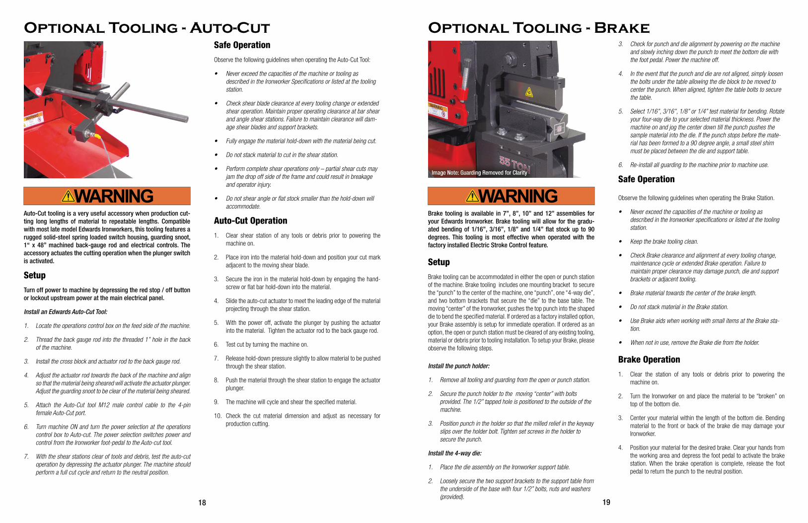
Brake tooling is available in 7”, 8”, 10” and 12” assemblies for your Edwards Ironworker. Brake tooling will allow for the gradu-ated bending of 1/16”, 3/16”, 1/8” and 1/4” flat stock up to 90 degrees. This tooling is most effective when operated with the factory installed Electric Stroke Control feature.
SetupBrake tooling can be accommodated in either the open or punch station of the machine. Brake tooling includes one mounting bracket to secure the “punch” to the center of the machine, one “punch”, one “4-way die”, and two bottom brackets that secure the “die” to the base table. The moving “center” of the Ironworker, pushes the top punch into the shaped die to bend the specified material. If ordered as a factory installed option, your Brake assembly is setup for immediate operation. If ordered as an option, the open or punch station must be cleared of any existing tooling, material or debris prior to tooling installation. To setup your Brake, please observe the following steps.
Install the punch holder:
1. Remove all tooling and guarding from the open or punch station.
2. Secure the punch holder to the moving “center” with bolts provided. The 1/2” tapped hole is positioned to the outside of the machine.
3. Position punch in the holder so that the milled relief in the keyway slips over the holder bolt. Tighten set screws in the holder to secure the punch.
Install the 4-way die:
1. Place the die assembly on the Ironworker support table.
2. Loosely secure the two support brackets to the support table from the underside of the base with four 1/2” bolts, nuts and washers (provided).
3. Check for punch and die alignment by powering on the machine and slowly inching down the punch to meet the bottom die with the foot pedal. Power the machine off.
4. In the event that the punch and die are not aligned, simply loosen the bolts under the table allowing the die block to be moved to center the punch. When aligned, tighten the table bolts to secure the table.
5. Select 1/16”, 3/16”, 1/8” or 1/4” test material for bending. Rotate your four-way die to your selected material thickness. Power the machine on and jog the center down till the punch pushes the sample material into the die. If the punch stops before the mate-rial has been formed to a 90 degree angle, a small steel shim must be placed between the die and support table.
6. Re-install all guarding to the machine prior to machine use.
Safe Operation
Observe the following guidelines when operating the Brake Station.
• Never exceed the capacities of the machine or tooling as described in the Ironworker specifications or listed at the tooling station.
• Keep the brake tooling clean.
• Check Brake clearance and alignment at every tooling change, maintenance cycle or extended Brake operation. Failure to maintain proper clearance may damage punch, die and support brackets or adjacent tooling.
• Brake material towards the center of the brake length.
• Do not stack material in the Brake station.
• Use Brake aids when working with small items at the Brake sta-tion.
• When not in use, remove the Brake die from the holder.
Brake Operation1. Clear the station of any tools or debris prior to powering the
machine on.
2. Turn the Ironworker on and place the material to be “broken” on top of the bottom die.
3. Center your material within the length of the bottom die. Bending material to the front or back of the brake die may damage your Ironworker.
4. Position your material for the desired brake. Clear your hands from the working area and depress the foot pedal to activate the brake station. When the brake operation is complete, release the foot pedal to return the punch to the neutral position.
Optional Tooling - Brake

Figure A
Incorrect use - material supported on one blade
Figure B
Correct use - material supported by two blades
Figure C
Correct use - material supported by three blades
20 21
Optional Notcher tooling will provide a distortion and burr free, three-sided shear cut to mild steel bar, plate, or angle stock as list-ed in the Ironworker Specifications as well as the capacity labels positioned adjacent to the Notching Station. The optional Notcher tooling for an Edwards Ironworker allows for shaped, straight or angled notch cutting applications.
SetupOptional tooling and accessories fit within the open station of the machine. Optional Notcher tooling is equipped with one, three-sided top notcher blade and three, four-sided bottom blades. The top blade is mounted to the moving “center” of the Ironworker, while the bottom three blades are secured into a base housing. If ordered as a factory installed option, your notcher assembly is setup for immediate operation. If ordered as an option, the open cavity of the machine must be cleared of any existing tooling, material or debris prior to tooling installation. Notcher blades are wearing parts and will need to be maintained or replaced over time. Refer to the Maintenance Manual for blade main-tenance, removal and replacement. To setup your Notching Station, observe the following steps.
Turn off power to machine by depressing the red stop / off button or lockout upstream power at the main electrical panel.
Install the top notcher blade:
1. Swing the notcher guard assembly up and away from the notcher table.
2. Install the top notcher blade with the keyway up and the “foot” of the blade facing the center of the machine. Secure the top blade using the two 3/8” socket head cap screws. Tighten bolts.
Install the notcher table:
1. Install the notcher table assembly to the base table. The notcher table includes three blades secured within the table housing. Install with the open “U” facing the center of the machine. The guide foot of the top blade should be centered within the base table blades.
2. Loosely secure the table from the underside of the base with four bolts and washers (provided).
3. Check for top and bottom blade alignment by powering up the machine and slowly inching down the top blade to meet the bot-tom blades with the foot pedal. Power the machine off.
4. Using a feeler gauge, adjust the clearance between the perimeter of the top and bottom blades to allow for .010 clearance on all three sides.
5. In the event that the top and bottom blades are not aligned, simply loosen the bolts under the table allowing the table to be moved to center the top blade within the bottom blades. When aligned, tighten the table bolts to secure the table.
6. Adjust the four set screws at the sides of the notcher table to engage the base notcher table to the base table. Lock the four 3/8” nuts in place to secure the set screws in place. These added fixtures are to provide additional support to the base table during the notching operation.
7. Swing the notcher guard back in place.
Safe OperationObserve the following guidelines when operating the Notcher Station.
• Never exceed the capacities of the machine or tooling as described in the Ironworker specifications or listed at the tooling station.
• Check notcher blade clearance at every tooling change or extended notcher operation. Maintain .010 clearance between top and bottom notcher blades at all times. Failure to maintain clear-ance will damage blades and support pockets.
• Cut with a minimum two of three sides of the blade surfaces en-gaging the material being notched. Cutting on one blade surface may overload the blades and result in tooling damage or injury to the Operator. See Figures A,B,C.
• Do not stack material to cut in the notcher station.
• Perform complete notch operations only – partial notch cuts may jam the drop off side of the tooling and could result in breakage and operator injury.
• Use notching aids when working with small items at the notcher
station.
Optional Tooling - Notcher 25/40/55/100 Ton Ironworkers Notcher Operation1. Clear the feed table of the notcher station of any tools or debris
prior to powering the machine on.
2. Turn machine on. The top notcher blade will be in the neutral posi-tion. Push the material under the tooling guard and into the blade area. Position your material to the desired cut.
3. Clear your hands from the working area and depress the foot pedal to activate the notcher station. When the cut is complete, release the foot pedal to automatically return the top notcher blade to the neutral position.

22 23
Most Edwards Ironworkers allow for Oversize Punch tooling to be installed in either the punch station or the open station. Refer to Ironworker Accessories specifications for capacities of oversize punch tooling.
SetupOversize punch tooling includes an oversize punch stripper’ oversize punch holder assembly, oversized die table or oversized pedestal die table and an oversized wrench. Punch and dies are wearing parts and will need to be maintained or replaced over time. Refer to the Maintenance Manual for removal and replacement instructions. When installiing over-size punch and die tooling please observe the following steps.
Turn off power to machine by depressing the red stop / off button or lockout upstream power at the main electrical panel.
Install the oversize punch holder:
1. Oversize punch tooling can be installed in either the punch station or the opposite, open station end of the Ironworker. Remove exist-ing tooling or debris from installation site.
2. Install oversize punch block /stem assembly to the moving center with hardware provided. Tighten assembly to moving center.
3. Insert oversize punch in oversize punch nut and thread onto over-size punch block /stem assembly. Tighten with wrench provided. If using a shaped punch, align the locating keystock of the punch with the corresponding slot within the punch stem assembly and tighten the punch nut with the wrench.
Install the oversize pedestal die table:
1. Clear the Ironworker base table of any debris.
2. Install the oversize die table with the die opening facing away from the Ironworker. Align the slotted holes of the die table with the base table holes and insert hardware provided.
3. With die table hardware loosely installed, insert die into die holder and secure with set screw.
4. Turn Ironworker on and inch down the punch to meet the die with the foot pedal jog control. Check to see that the punch is centered within the die.
5. Once punch is aligned with die, turn off power to machine; secure the die table to the Ironworker base table by tightening the hard-ware provided.
6. Install the oversize punch stripper assembly to the Ironworker frame with the hardware provided.
7. Swing the stripper bar into place allowing for minimal clearance between the top of the material to be punched and the bottom of the stripper and tighten the stripper bar bolts.
Safe Operation Observe the following guidelines when operating the Oversize Punch tooling.
• Follow manufacturers punch and die clearance and tonnage recommendations as shown (Figure1, Punch Operation) in this manual.
• Never exceed the capacities of the machine or tooling as de-scribed in the specifications or listed at the tooling station.
• The thickness of the material you are punching should not exceed the diameter of the punch being used.
• Check punch and die alignment after every tooling change.
• Adjust the punch stripper supplied with your Edwards Ironworker to allow for material positioning and material stripping.
• Do not stack material to punch in the punching station.
• Use 1 - 2 drops of oil at the punch to aid in stripping material from the punch as well as to extend the life of the punch tooling.
• Punch complete holes only – partial holes will side load the punch tooling and could result in punch breakage and operator injury.
• Use punch aids when working small items at the punch station.
Oversize Punch Tooling Operation1. Clear the punch station of any tools or debris prior to powering the
machine on.
2. Place the material to be punched between the punch and die. Check to see that your material is spanning the stripper plate and that adequate material is avaiable to safely position the material.
3. Clear your hands from the working area and depress the foot pedal to move the punch through the material and into the die.
4. When the punch is complete, release the foot pedal to automati-cally strip the material from the punch and return the punch to its neutral position.
Optional Tooling - Oversize Punch
Pipe-Notch tooling will provide a distortion and burr free,notch cut to mild steel pipe and tube stock. Common use of this tooling is in the fabrication of saddle connections for motorcycle and race car tube frames, tube fences etc. Please review the capacity labels listed in the Ironworker Accessories specifications as well as posi-tioned at the Pipe-Notching Station.
SetupPipe Notch tooling fits within the open station of the machine. A Pipe-Notch tooling assembly includes one push block, one top notcher die, one bottom notcher die and a die table. Pipe Notch Tooling for the 100 Ton Deluxe and 120 Ton Ironworkers also includes a slug chute. The top die is mounted within a spring loaded guide housing mounted to the die table. The bottom die attaches to the face of the guide housing and is machined with a saddle to aid in centering and guiding pipe sections into the die housing. The moving “center” of the Ironworker, pushes on the top Pipe-Notch blade via the accessory push block. If ordered as a factory installed option, your Pipe Notcher assembly is setup for immedi-ate operation. If ordered as an option, the open cavity of the machine must be cleared of any existing tooling, material or debris prior to tooling installation. To setup your Pipe-Notching station please observe the fol-lowing steps.
Turn off power to machine by depressing the red stop / off button or lockout upstream power at the main electrical panel.
Install the push block:
1. Remove all tooling and guarding from the open station.
2. Install the push block supplied with the Pipe-Notcher assembly to the moving center of the Ironworker. Secure the push block with bolts provided.
Install the Pipe notcher Assembly:
1. Place the Pipe-Notcher assembly on the Ironworker support table with the bottom die pointing away from the machine.
2. Loosely secure the table from the underside of the base with four 1/2” bolts and washers (provided).
3. Check for push block and top die alignment by powering on the machine and slowly inching down the push block to meet the top die with the foot pedal. Power the machine off.
4. In the event that the push block and top die are not aligned, simply loosen the bolts under the table allowing the table to be moved to center the push block centerline to the top blade. When aligned, tighten the table bolts to secure the table.
5. Power the machine on and jog the center down. The pipe dies will close or bypass each other. The push block should not come in contact with the die housing.
Safe OperationObserve the following guidelines when operating the Pipe-Notch tooling.
• Never exceed the capacities of the machine or tooling as described in the Ironworker specifications or listed at the tooling station.
• Keep the Pipe Notch tooling clean. When dirt or metal chips accu-mulate, remove 5/16-18 x 1/2” limit screw located in the center at the rear of punch. Lift out punch holder and two springs. Clean holder with solvent or kerosene.
• Check Pipe Notcher blade clearance and alignment at every tooling change, maintenance cycle or extended notcher operation. Maintain .010 clearance between notcher blades at all times. Failure to maintain clearance will damage blades and support pockets.
• Do not stack material to cut in the Pipe-Notcher station.
• Perform complete notch operations only – partial notch cuts may jam the drop off side of the tooling and could result in breakage and operator injury.
• Use notching aids when working with small items at the notcher station.
Pipe Notcher Operation1. Clear the feed table of the Pipe-Notcher station of any tools or
debris prior to powering the machine on.
2. Turn machine on. The top notcher die will be in the neutral position. Push the material into the blade area. Position your material to the desired cut.
3. Clear your hands from the working area and depress the foot pedal to activate the Pipe Notcher station. When the cut is complete, release the foot pedal to automatically return the top notcher die to the neutral position.
Optional Tooling - Pipe Notcher

24 25
“Bump-die” shear tooling is available for your Edwards Ironwork-er. Rod Shear or Multi Shear Tooling will provide distortion and burr free cuts to mild steel rod, square, bar and small angle stock as listed in the Ironworker Accessories specification.
Setup“Bump-die” tooling and accessories fit within the punch station, open station or open tooling cavity of the machine. Verify recommended loca-tion per Ironworker model below. Edwards “bump-die” tooling consists of a housing which holds a stationary blade, a moving blade, return springs and a push block. The moving “center” of the Ironworker, “bumps” the top moving blade via the push block to shear the material. If ordered as a factory installed option, your “bump-die” assembly is setup for imme-diate operation. If ordered as an option, the open or punch cavity of the machine must be cleared of any existing tooling, material or debris prior to tooling installation. To setup your Rod Shear or Multi Shear Tooling please observe the following steps.
Identify install location:
25 Ton open station 40 Ton open station 50 Ton punch station 55 Ton open or punch station 60 Ton punch station 65 Ton punch station or open cavity 75 Ton punch station 100 Ton open or punch station 100 Ton Deluxe punch station 120 Ton open cavity
Install the bump-die assembly:
1. Remove all tooling and guarding from the appropriate open, punch or open cavity station.
2. Place the “bump-die” assembly on the Ironworker support table with the push block in line with the moving center.
3. Loosely secure the table from the underside of the base with four 1/2” bolts and washers (provided).
4. Check for push block and moving center alignment by powering on the machine and slowly inching down the center to meet the push block with the foot pedal. Power the machine off.
5. In the event that the push block and top die are not aligned, simply loosen the bolts under the table allowing the bump-die to be moved to center the push block with the moving center. When aligned, tighten the table bolts to secure the table.
6. Power the machine on and jog the center down. The moving blade will close or bypass the fixed blade. The push block should not come in contact with the die housing.
Safe OperationObserve the following guidelines when operating any Rod Shear or Multi Shear bump-die tooling
• Never exceed the capacities of the machine or tooling as described in the Ironworker specifications or listed at the tooling station.
• Keep the tooling clean.
• Check blade clearance and alignment at every tooling change, maintenance cycle or extended tooling operation. Maintain .010” clearance between blades at all times. Failure to maintain clear-ance will damage blades and support pockets.
• Do not stack cut material.
• Perform complete shearing operations only – partial cuts may jam the tooling and could result in breakage and operator injury.
• Use shearing aids when working with small items at the Rod Shear or Multi Shear Tooling station
Rod Shear/Multi-Shear Operation1. Clear the work area of any tools or debris prior to powering the
machine on.
2. Turn the Ironworker on and insert material through the tooling guard and into the blade area. Position your material for the desired cut.
3. Clear your hands from the working area and depress the foot pedal to activate the tooling station.
4. When the cut is complete, release the foot pedal to automatically return the tooling to the neutral position.
Optional Tooling - Rod Shear/Multi-Shear Optional Tooling - 241 Punch
Your Ironworker is capable of punching materials as listed in the Ironworker Specifications as well as described on the capacity la-bels positioned at the Punch Station.
Setup241 Punch tooling fits within the open or standard punch station of the machine. 241 Punch tooling includes an oversize punch stripper, punch holder assembly, die table and wrench. Punch and dies are wearing parts and will need to be maintained or replaced over time. Refer to the Maintenance Manual for removal and replacement instructions. When installing 241 punch and die tooling please observe the following steps.
Turn off power to machine by depressing the red stop / off button or lockout upstream power at the main electrical panel.
Install the punch holder:
1. Clear any tooling or debris from the tooling installation site.
2. Secure the 241 punch holder to the operating center by first re-moving the stud from the holder. Place the holder to the operating center with the tapped hole positioned to the outside of the center. Install holder with two 1/2” SHCS bolts and tighten. Install stud to holder with four 3/8” SHCS bolts and tighten.
Install the die table:
1. Place the 241 die table and slug chute on the support table base and loosely install four 1/2” bolts (provided) through the underside of the support table into the 241 die table.
2. Install new oversize die and tighten set screw. If loading a shaped die, align the whistle spot with the set screw and tighten.
3. Install new 241 punch and tighten with spanner wrench. If using a shaped punch, align the locating keystock (not provided) of the punch with the corresponding slot within the punch stem assem-bly and tighten the punch nut with the wrench.
4. Check for punch and die alignment by powering up the machine and slowly inching down the punch to meet the die with the foot pedal. Check to see that the punch is centered in the die. Turn off power to machine.
5. In the event that the punch and die are not aligned, simply loosen the bolts under the table allowing the table to be moved to center the die. When aligned, tighten the table bolts to secure the table.
6. Install and secure the 241 stripper bar to the ironworker frame allowing for minimal clearance between the top of the material to be punched and the bottom of the stripper.
Safe OperationObserve the following guidelines when operating the 241 Punch Station.
• Follow manufacturers punch and die clearance recommendations as shown (Figure1, Punch Operation) in this manual.
• Never exceed the capacities of the machine or tooling as described in the Ironworker specifications or listed at the tooling station.
• The thickness of the material you are punching should not exceed the diameter of the punch being used
• Check punch and die alignment after every tooling change or extended punch operation.
• Adjust the punch stripper supplied with your 241 tooling to allow for material positioning and material stripping.
• Do not stack material to punch in the punching station.
• Use one or two drops of oil at the punch to aid in stripping mate-rial from the punch as well as to extend the life of the punch tooling.
• Punch complete holes only – partial holes will side load the punch tooling and could result in punch breakage and operator injury.
• Use punching aids when working with small items at the punch station.
241 Punch Operation 1. Clear the punch station of any tools or debris prior to powering the
machine on.
2. Turn the Ironworker on and place the material to be punched between the punch and die. Adjust the punch stripper for mini-mum clearance between stripper plate and material. Check to see that your material is spanning the stripper plate and that adequate material is available beyond the stripper area to safely position the material.
3. Clear your hands from the working area and depress the foot pedal to move the punch through the material and into the die. When the punch is complete, release the foot pedal to automatically strip the material from the punch and return the punch to its neutral position.

26 27
The Hydraulic Accessory Package is a factory installed option that is ready to power any Edwards branded hydraulic accessory tools. The Hydraulic Accessory Package includes hydraulic input and output quick connect/disconnect hardware and a series of female M12 and Mil Spec connections allowing for the control of your hy-draulic accessory tool, limit switch and auto-cut tooling. To install your accessory tool please observe the following steps.
SetupTurn off power to machine by depressing the red stop / off button or lockout upstream power at the main electrical panel.
Install an Edwards Hydraulic Accessory Tool:
1. Locate the operations control box adjacent to the starter box on the feed side of the machine.
2. Locate the hydraulic quick connections and accessory controls adjacent to drop-off side or end cap of the machine.
3. LOCATE EDWARDS HYDRAULIC ACCESSORY TOOL IMMEDIATELY ADJACENT TO IRONWORKER.
4. With the Ironworker power off, install the male and female acces-sory hydraulic hoses to the ironworker male and female quick con-nect hydraulic fittings. Both fittings have a detent ball setting that must be aligned to couple and uncouple hoses.
5. Attach the accessory tool male M12 power cable, to the M12 female limit switch port.
6. Remove the safety cap at the Push Button Port. Attach the acces-sory tool control OUT / IN, male Mil Spec control cable to the Mil Spec female accessory control port.
7. Turn machine ON and turn the power selection at the operations control box to Accessory. The power selection switches power and control from the Ironworker to the accessory tool.
8. REFER TO THE SAFETY, INSTALLATION, OPERATIONS AND MAINTENANCE MANUALS OF YOUR EDWARDS HYDRAULIC ACCESSORY TOOL PRIOR TO OPERATION.
9. When Disconnecting your Hydraulic Accessory, Simply reverse procedure. Replace the Safety Cap at the push button port to restore power to your Ironworker.
Optional Tooling - Hydraulic Accessory PackageAccessory Light
Your Edwards Ironworker may have been shipped with onboard lighting. Accessory lighting is available as optional tooling. Designed with M12 connections, this super bright LED light plugs in to 2014 and newer Edwards Ironworkers and has a 100,000 hour rating. Super durable lexan lens and magnetic base allow you to attach the light on any Ironworker surface.
Accessory work lights contain magnets - Magnet Safety Warning!
Disclaimer: Edwards Manufacturing neither assumes nor accepts any liability for damages resulting from the handling or use of magnets. With your purchase, the buyer confirms that you have read and understood the following warnings, the buyer agrees that he/she is re-sponsible for all damages and injuries caused by magnets, which may include personal injuries, property and magnet damages. The buyer agrees with these terms at time of purchase.
Neodymium magnets are very strong. Handling them with care is necessary to prevent personal injuries, property damages and magnet damages.
1. Neodymium magnets are brittle; they can be broken or can splinter in a collision. One should wear gloves and protective glasses when handling these magnets, because splinters could disengage and fly from the magnets.
2. Normal Neodymium magnets will lose their magnetic proper-ties if heated above 175°F (80° C).
3. The strong magnetic fields of neodymium magnets can damage items such as television, computer monitors, credit cards, bank cards, computers, diskettes and other data carriers, video tapes, mechanical watches, hearing aids, loud speakers and VCRs. Pace-makers may be damaged or switch to “Test Mode” in the presence of a strong magnetic force, if a pace-maker is in use, keep a minimum of 3 feet distance.
4. Children should not be allowed to handle neodymium mag-nets as they can be dangerous. Small magnets pose a choking hazard and should never be swallowed or inserted into any part of the body.
5. Under no circumstances should you try to cut, saw or drill the Neodymium magnets! The resulting dust from the magnet is very flammable.

28
Your Edwards Ironworker is designed for years of trouble-free use. In the event of operational problems, refer to the following troubleshooting strategies prior to contacting your Edwards Dealer. Turn off power to machine by depressing the red stop / off button or lockout upstream power at the main electrical panel before any trouble shooting activity.
Problem SolutionMachine will not run Check safety cap at Hydraulic Accessory Pack installed Twist E-stop if depressed Check the mode Ironworker/Accessory/Auto Cut Confirm the correct voltage Check fuses
Machine runs but will not cycle Check rotation of motor Check correct amp/voltage to machine Check drive key is in place Check foot pedal cable obstruction Check power supply for green light Check electric foot pedal for obstruction Check proximity switches
Machine cycles down but will not return to neutral position Check rotation of motor Check return spring at valve Check foot pedal linkage
Machine turns off after short time in use Check correct amp/voltage to machine
Electric stroke option malfunction Check correct amp/voltage to machine Check fuse at starter box Check fuse at transformer box Check for loose microswitch connections Check for damaged microswitch
Distortion of small angle shear cut Check radius orientation of blade
Brass shavings below gib-pins and slides Brass shavings are common and expected during the break-in period and after blade maintenance
Hydraulics feel hot after operation Hydraulic system operates within the 160 – 190 degree range
Shear blades or punch and die do not close completely Check for notch tooling obstruction Check for brake tooling obstruction
Punch and die misalignment Check that punch is tight in holder Check that punch stud is secure in block Check for table alignment
Machine will not complete punch or shear operation Check tonnage of machine rating against steel hardness and thickness Check for work station obstruction Check foot pedal linkage Check hydraulic fluid level Check slides for wear or obstruction Check electric stroke control option Check die support plate
Hydraulic oil overflow/foaming at breather cap Check hydraulic fluid level Check for loose hose coupling
Troubleshooting

SP.O. Box 166, Albert Lea, MN 56007 800-373-8206 www.edwardsironworkers.com