operator manual & parts catalog - … · operator manual & parts catalog ... - blade...
TRANSCRIPT
OPERATOR MANUAL & PARTS CATALOG
143263 v1.3D E G E L M A N I N D U S T R I E S L T D.B O X 8 3 0 - 2 7 2 I N D U S T R I A L D R I V E ,R E G I N A , S K , C A N A D A , S 4 P 3 B 1FA X 306.543.2140 P H 3 0 6 . 5 4 3 . 4 4 4 71 . 8 0 0 . 6 6 7 . 3 5 4 5 D E G E L M A N . C O M


QUICK GUIDE INDEX
Table of Contents -
Introduction 1
Safety 3
How To Set Your Tractor 8
How To Hook-Up Your Cutter 9
Cutter Preparation 12
How To Set Your Cutter 13
How To Operate Your Cutter 17
Transporting 19
Troubleshooting 21
Maintenance & Service 25
How To Store Your Cutter 32
Attachments / Accessories 33
Parts 40
Warranty 85
D E G E L M A N I N D U S T R I E S L T D.B O X 8 3 0 - 2 7 2 I N D U S T R I A L D R I V E ,R E G I N A , S K , C A N A D A , S 4 P 3 B 1FA X 306.543.2140 P H 3 0 6 . 5 4 3 . 4 4 4 71 . 8 0 0 . 6 6 7 . 3 5 4 5 D E G E L M A N . C O M
IMPORTANT:
READ MANUAL


1. Introduction and Specifications..............01- 02
2. Safety - Important Safety Information ..................03 - General Safety... ....................................04 - Safety Decals ........................................05 - Decal Placement ....................................06
3. How To Set Your Tractor - Tractor Requirements.. ............................08 - Correct PTO Speed ................................08 - Positioning Tractor Drawbar ...................08 - Correct Drawbar Length .........................08 - 3 Point Quick Coupler Hitch Removal ......08 - Wheel Tread Width Settings ...................08
4. How to Hook-Up Your Cutter - Attaching Cutter to Tractor Drawbar........ 09 - Installing Safety Chain ...........................10 - Attaching Driveline to PTO .....................10 - Attaching Hydraulics ..............................10 - Connecting Lights (optional) ....................10 - Detaching Cutter from Tractor .................10
5. Cutter Preparation - Preparation Checklist .............................12 - Cutting Banding Strap...... ......................12 - Removing Transport Locks & Lowering Wings....................................12 - Setting Hydraulic Flow Speed .................12
6. How to Set Your Cutter - Important Setting Information................. 13 - Phasing Cylinders .................................13 - Engaging Driveline Clutch ......................13 - Levelling Front to Back ............................14 - Levelling Side to Side .............................15 - Why Blade Rotation is Important............. 16 - Setting Cutting Depth .............................16 - Wheel Tread Width Settings ...................16
7. How to Operate Your Cutter - Safe Operating Procedures ....................17 - Raising Wings .......................................18 - Wing Flotation ......................................18 - Cutting Angles .......................................18 - Blade Rotation .......................................18 - Making Turns ........................................18
8. Transporting - Safe Transport Procedures ......................19 - Preparing Cutter for Transport .................20 - Restricted Transport Width ......................20
9. Troubleshooting - General Operation................................ 21
10. Troubleshooting - Components - Operation............................................. 22 - Blades ..................................................23 - Gear Boxes ...........................................23 - Driveline Clutches ..................................24 - Drivelines .............................................24
11. Maintenance & Service - Safe Maintenance Procedures .................25 - 4 Hour ..............................................26 - 8 Hour (Daily) ...................................26 - 20 Hour ..............................................27 - 50 Hour ..............................................27 - 100 Hour .............................................27 - Annually ...............................................28 - Blades ..................................................29 - Blade Hardware ....................................29 - Blade Carriers (or optional Skid Pans)..... 29 - Torque Specifications............................. 30 - Torque Limiter Disassembly..................... 31 - Torque Limiter Assembly .........................31
12. How to Store Your Cutter - Preparing for Storage ............................32 - Removing from Storage .........................32
13. Attachments / Accessories - Aircraft Tires, Brush Blade, Shredder Kit Light Kit, Tow Hitch, Clevis Hitch, & Toolbox.................................................33 - Winch Kit (Operating Instructions) ...........34
14. Parts...................................................... 40 - General Assembly................................. 40 - Center Frame...................................41- 42 - Right & Left Wing Frame........................ 43 - Counterweight Assembly (1030)............. 44 - Hitch Assembly...................................... 45 - Center Shield and Hydraulic Clamps....... 46 - Rockshaft Assembly................................ 47 - Wheel Strut Assembly............................ 48 - Wheels, Hubs, & Spindles...................... 49 - Blades, Pan, & Hardware....................... 50 - Hydraulic Schematics........................51- 52 - Hydraulic Cylinders..........................53- 54 - Drivelines.........................................55- 63 - Torque Limiter................................... 66-67 - Gearboxes.......................................68- 82 - Optional Lighting Kit.........................83- 84 - Optional Winch Kit................................ 85 - Optional Toolbox or Tow Hitch................ 86
15. Warranty...................................................... 87
Table of Contents

-1-143263 - Rotary Cutter 1030/1530 (23-April-2010)
Introduction
This manual has been designed to help you with three extremely important issues: Operation, Safety, and Maintenance. It is strongly recommended that you read through the entire manual and review it annually for: • your own personal safety. • the safety of others. • helpful and effective operation techniques. • maintenance procedures. • preventative maintenance.
Your authorized Degelman dealer can be contacted for ordering any replacement parts, decals, or manuals. Since many of our parts are specially designed specifically for this Rotary Cutter we strongly recommend you always replace them with genuine Degelman parts only.
This manual and its contents were current at the time of its first printing. To increase product performance and operation, some part modifications and changes may occur that are not reflected in this manual.
Note: The description “Right”or“Left” as used in this manual is determined by the direction the tractor will travel while in use (unless otherwise stated).
Degelman is proud to welcome you to our rapidly increasing family of high quality and dependable product owners. This product was designed and built specifically for you, the customer. Through our research and with your input and feedback, we present to you our 1030 & 1530 Rotary Cutter.
Designed with durability, safety, and performance in mind, this rotary cutter is ready for years of quality service. In order to help you keep your rotary cutter in top operating condition we have provided you with this manual.
Serial Number Plate
Your serial number is found on the serial number plate attached to the cutter on the front left side of the cutter near the driveline shield (shown in the photo above).
It is important to record the serial and model number of your cutter for proof of ownership and for any required service or maintenance assistance.
Serial Number Owner Model
PTO Speed: 540 RPM 1000 RPM
Gearboxes: OMNI Bondioli & Pavesi
Drivelines: Weasler Bondioli & Pavesi
The 1030 Rotary Cutter Model consists of a center assembly and one wing section. The over all cutting width is 10 feet 2 inches.
The 1530 Rotary Cutter Model consists of one center assembly and two wing sections. The overall cutting width is 15 feet.
Wing angle and machine cutting height are independantly controlled with hydraulic cylinders. The cutter maintains a level cut at all cutting heights with our self-leveling system and unique double acting suspension.
Welcome Proof of Ownership
About This Manual
Description
LeftSide
RightSide

-2-143263 - Rotary Cutter 1030/1530 (23-April-2010)
Specifications and Options
Chain Shield:
Standard Double Row - 5/16” GR 30
Optional Cable through Chain - 1/4” Cable
Deck Rings: 1/2” x 3” Standard
Side Skirt Thickness: Laminated up to 7/16” thick
Minimum Tractor PTO Power: 65 hp
Recommended Tractor PTO Power: 85 hp
Wing Lift Hydraulics: (Routing for combined circuit included)
Standard Single acting individual circuits
Hitch: Self-leveling
Standard 1-1/4” Precision Clamping System
Optional 1-1/8” Clevis Hitch
Suspension:
Center: Walking Axle and Rubber Spring
Wings: Standard Single Wheel and Rubber Spring
Optional Walking Axle and Rubber Spring
Wheels/Tires:
Standard 5 Bolt 20x5.5 Laminated
Optional 5 Bolt 22x6.6 Aircraft (foam filled)
Optional 5 Bolt 22x6.6 Aircraft (air filled)
Optional Accessories:
Light Kit, Toolbox, Wing Guide Wheel, Winch Kit, Tow Kit
ROTARY CUTTER RC1530 & RC10301030 model specs. shown in ( )’s.
Field Position:
Cutting Height 1” to 17”
Cutting Width 180” (122”)
Overall Width 188” (135”)
Overall Length 191”
Transport Position:
Overall Height 86”
Overall Width (no wheels) 90” (87”)
Overall Width (with wheels) 120” (102”)
Overall Length 180”
Ground Clearance: 16”
Weight: Standard 5985 lbs (6100 lbs)
Hitch Weight:
Field Position 2100 lbs (2125 lbs)
Transport Position 1950 lbs (1975 lbs)
Wing Flex: 24° down, 85° up
Deck Thickness - Double Frame Construction:
Top Deck 3/16”
Bottom Deck (High Impact Resistant Steel) 3/16”
Skid Shoes:
Wing 3/8” x 3” AR400
Center Section 3/8” x 5-1/2” AR400
Blade Tip Speed: 540 PTO 1000 PTO
Center 15,500 ft/minute 16,750 ft/minute
Wing 15,700 ft/minute 15,950 ft/minute
Brush Cutting Capacity: 3-1/2”
Blade Holder:
Standard 3/4” Blade Carrier
Optional 1/4” Reinforced Skid Pan
Blades: Milled, 6-1/4” Overlap
Standard 1/2” x 5”
Optional 1/2” x 4”
Gearcase Power Rating:
Transfer Gearcase: Center and Wing Gearcase:
200 hp - continuous 175 hp - continuous
240 hp - peak 190 hp - peak
Drivelines:
540 RPM Machine Gearcases
Tractor to Transfer CAT 6 with 80° CV
Transfer to Center/Wing CAT 4
1000 RPM Machine Gearcases
Tractor to Transfer CAT 4 with 80° CV
Transfer to Center/Wing CAT 4
Driveline Protection: Preset Friction Torque Limiters
BONDILI & PAVESI MODELS
Blade Tip Speed: 540 PTO 1000 PTO
Center 17,030 ft/minute 16,750 ft/minute
Wing 17,030 ft/minute 15,950 ft/minute
Brush Cutting Capacity: 4”
Blade Holder:
Standard 3/4” Blade Carrier
Blades: Milled, 7-1/2” Overlap
Standard 1/2” x 5”
Optional 1/2” x 4”
Gearcase Power Rating:
Transfer Gearcase: Center and Wing Gearcase:
200 hp - continuous 175 hp - continuous
250 hp - peak 200 hp - peak
Drivelines:
540 RPM Machine Gearcases
Tractor to Transfer CAT 6 with 80° CV
Transfer to Center/Wing CAT 5
1000 RPM Machine Gearcases
Tractor to Transfer CAT 5 with 80° CV
Transfer to Center/Wing CAT 5
Driveline Protection: Preset Friction Torque Limiters
OMNI GEAR & WEASLER MODELS

DANGER
WARNING
CAUTION
-3-143263 - Rotary Cutter 1030/1530 (23-April-2010)
The Safety Alert Symbol identifies important safety messages applied to the Rotary Cutter mower and in this manual. When you see this symbol, be alert to the possibility of injury or death. Follow the instructions provided on the safety messages. The Safety Alert Symbol means:
ATTENTION! BECOME ALERT!
YOUR SAFETY IS INVOLVED!
DANGER: Indicates an imminently hazardous situation that, if not avoided, WILL result in death or serious injury if proper precautions are not taken.
WARNING: Indicates a potentially hazardous situation that, if not avoided, COULD result in death or serious injury if proper precautions are not taken.
CAUTION: Indicates a potentially hazardous situation that, if not avoided, MAY result in minor or moderate injury if proper practices are not taken, or, serves as a reminder to follow appropriate safety practices.
Why is SAFETY important to YOU?
3 BIG Reasons:
•Accidents Can Disable and Kill •Accidents Are Costly •Accidents Can Be Avoided
Note the use of the Signal Words: DANGER, WARNING, and CAUTION with the safety messages. The appropriate Signal Word has been selected using the following guidelines:
Safety
Safety Alert Symbol
Signal Words

-4-143263 - Rotary Cutter 1030/1530 (23-April-2010)
Safety
Peligro: Si no lee Ingles, pida ayuda a alguien que si lo lea para que le traduzca las medidas de serguridad.
Danger: Si vous ne compreniez pas l’anglais, demanderiez à quelqu’un qui comprend l’anglais pour traduire tous les messages de sécurité qui se trouve dans ce manuel.
Danger: Do not operate the tractor or rotary cutter until you have fully read and completely understand this operators manual, your tractor’s operators manual, and all the safety messages found within these manuals, on the products, or other included materials.
Prepare for Emergencies
• Be prepared if a fire starts.
• Keep a first aid kit and fire extinguisher handy.
• Keep emergency numbers for doctor, hospital, ambulance, and fire department near your phone.
Doctor Ambulance Hospital Fire Department
General Safety
Wear Protective Equipment
• Wear proper safety equipment such as safety glasses and shoes, hearing protection, hard hats, or any other appropriate items to prevent injury.
• Wear close fitting clothing to help prevent accidental
entanglement.
Note: Always stop tractor engine and wait for all moving parts to stop before approaching equipment.
• Loss of hearing or hearing impairment may result from prolonged exposure to loud noise. Wear
suitable hearing protective devices such as earmuffs or earplugs to protect your hearing.
• Safely operating this equipment requires the full attention of the operator. Do not wear radio or music headphones, or talk on your phone while operating this machine. Never operate while under the influence of alcohol or drugs or allow anyone under the influence to operate the tractor or rotary cutter.

-5-143263 - Rotary Cutter 1030/1530 (23-April-2010)
Safety
Decal Part # - 143128
Decal Part # - 143130
Decal Part # - 143125
Decal Part # - 143148
Decal Part # - 143146 Decal Part # - 143147
Safety Decals
Decal Part # - 143126
Decal Part# - 143127
Decal Part # - 143129
Decal Part # - 143171
Decal Part # - 143124
Read and Understand all Safety Decals BEFORE Operating
Important:
• Understanding and following the information found on these safety decals can save your life and extend the life expectency of your cutter. • Keep safety signs and decals clean and legible at all times. • If saftey signs or decals are missing or illedgible they must be replaced. • If repair work causes any decals to be damaged or removed they must be replaced. • Safety decals for replacement are availble by request. Call toll free: 1.800.667.3545
Decal Part # - 142557 - Amber Relflector 2” x 9”
Decal Part # - 142556 - Red Relflector 2” x 9”
Decal Part # - 142280 - Red Relflector 2” x 6-1/4”
OMNI Only
OMNI Only
14
16
15
13
1
7
14or
910 or
6
5
122
17
7
4
18
2
3
1919
20 20
21
11
8
3
23
22 24
2224
-6-143263 - Rotary Cutter 1030/1530 (23-April-2010)
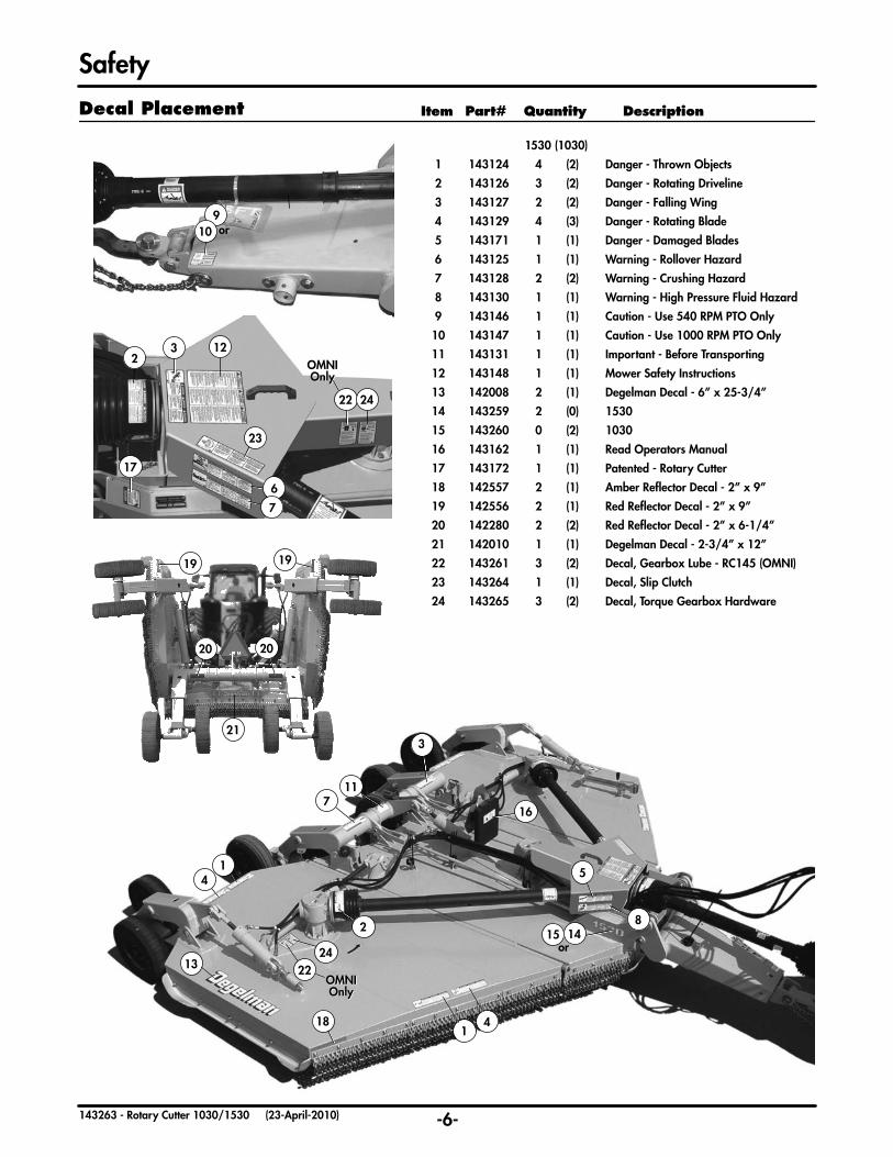
Safety Item Part# Quantity Description
1530 (1030)
1 143124 4 (2) Danger - Thrown Objects
2 143126 3 (2) Danger - Rotating Driveline
3 143127 2 (2) Danger - Falling Wing
4 143129 4 (3) Danger - Rotating Blade
5 143171 1 (1) Danger - Damaged Blades
6 143125 1 (1) Warning - Rollover Hazard
7 143128 2 (2) Warning - Crushing Hazard
8 143130 1 (1) Warning - High Pressure Fluid Hazard
9 143146 1 (1) Caution - Use 540 RPM PTO Only
10 143147 1 (1) Caution - Use 1000 RPM PTO Only
11 143131 1 (1) Important - Before Transporting
12 143148 1 (1) Mower Safety Instructions
13 142008 2 (1) Degelman Decal - 6” x 25-3/4”
14 143259 2 (0) 1530
15 143260 0 (2) 1030
16 143162 1 (1) Read Operators Manual
17 143172 1 (1) Patented - Rotary Cutter
18 142557 2 (1) Amber Reflector Decal - 2” x 9”
19 142556 2 (1) Red Reflector Decal - 2” x 9”
20 142280 2 (2) Red Reflector Decal - 2” x 6-1/4”
21 142010 1 (1) Degelman Decal - 2-3/4” x 12”
22 143261 3 (2) Decal, Gearbox Lube - RC145 (OMNI)
23 143264 1 (1) Decal, Slip Clutch
24 143265 3 (2) Decal, Torque Gearbox Hardware
Decal Placement

-7-143263 - Rotary Cutter 1030/1530 (23-April-2010)

14 inches
-8-143263 - Rotary Cutter 1030/1530 (23-April-2010)
How To Set Your Tractor
The rotary cutter is available in either a 540 rpm PTO speed or a 1000 rpm PTO speed. Many tractors are equipped with both 540 and 1000 rpm PTO modes. Be sure that the PTO speed of the tractor matches the rotary cutter’s gearbox speed.
Caution: Under no circumstances should you try to operate a 540 rpm PTO cutter with a 1000 rpm PTO tractor, and likewise do not operate a 1000 rpm PTO cutter with a 540 rpm PTO tractor. Do not use PTO adapters. PTO adaptors will cause driveline failure and possible tractor damage, it will also invalidate your warranty.
1. Remove drawbar side locking pins and movedrawbar into center position.
2. Install drawbar locking pins.
3. Remove clevis or hammer strap assembly, if equipped.
We recommend a tractor with all of the followingrequirements:
• A full cab or at least one with ROPS (Rollover Protective System).
• A working seat belt.
• At least 65 PTO HP.
• A minimum static vertical load rating of drawbar of 2100 lbs or greater.
The rotary cutter’s driveline is equipped with a constant velocity joint enabling the cutter to operate at difficult angles. For this reason we recommend the drawbar length for all PTO modes to be set at14 inches (typically specified for a 540 rpm PTO).Do not use a distance shorter than 14 inches or slider damage may result.
This shorter distance will reduce the hitch loading and stress on your drawbar. (Please consult your tractor’s operator manual for correct drawbar adjustment procedures.)
Caution: To prevent damage to the tractor drawbar, avoid travelling at high speeds and over rough terrain. Heavy drawn equipment such as this cutter can place excessive strain on the drawbar.
Caution: To prevent machine damage during turns, the 3 point quick coupler hitch must be removed and the draft link height be adjusted.
1. Remove quick coupler hitch from tractor.
2. To clear driveline during turns, adjust draft link to provide highest lift possible.
It is important to increase the tractor rear wheel tread width to maintain tractor stability when working on inclines or rough ground. (Please consult your tractor’s operator manual for correct adjustment procedures.)
Caution: Rear tires may be damaged if hitch is contacted during turns. Check for tire clearance at hitch uprights when making tight turns.
Correct PTO Speed
Tractor Requirements
Positioning Tractor Drawbar
Correct Drawbar Length
3 Point Quick Coupler Hitch Removal
Wheel Tread Width Settings

Loosen Adjust Tighten
-9-143263 - Rotary Cutter 1030/1530 (23-April-2010)
CLEVIS HITCH HOOk-UP
1. Ensure the settings in the “How To Set Your Tractor” section have been completed.
2. Pin cutter clevis into the supported position for hook-up
using the clevis support pin.
3. Adjust cutter height with jack to allow enough height for tractor drawbar.
4. Remove hitch pin from tractor drawbar or cutter hitch.
5. Clear the area of bystanders, back up tractor to cutter, aligning tractor drawbar with cutter hitch.
6. Engage tractor parking brake and/or place transmission in “Park”, shut off tractor engine, and remove key.
7. Remove hitch clevis support pin and place into its storage position.
8. Install and secure drawbar pin. Lower cutter onto drawbar.
9. Remove jack and place in proper storage position.
Note: You may wish to adjust jack mount angle prior to jack removal and storage.
(refer to “Jack Mount Adjustment” diagram below).
10. Install Safety Chain, refer to the “Installing Safety Chain” section (pg.10).
How To Hook-Up Your Cutter
PRECISION HITCH HOOk-UP
1. Ensure the settings in the “How To Set Your Tractor” section have been completed.
2. Pin hitch into the supported postition for hook-up using the hitch support pin.
3. Adjust cutter height with jack to allow enough height for tractor drawbar.
4. Remove hitch pin from tractor drawbar and/or cutter hitch.
5. Clear the area of bystanders, back up tractor to cutter, aligning tractor drawbar with cutter hitch.
6. Engage tractor parking brake and/or place transmission in “Park”, shut off tractor engine, and remove key.
7. Remove cutter hitch support pin and place into its storage position.
8. Lower cutter onto drawbar. Install and secure hitch bolt. (refer to “Precision Hitch
Installation” diagram below)
9. Remove jack and place in proper storage position.
Note: You may wish to adjust jack mount angle prior to jack removal and storage.
(refer to “Jack Mount Adjustment” diagram on left).
10. Install Safety Chain, refer to the “Installing Safety Chain” section (pg.10).
Attaching Cutter to Tractor Drawbar
JACk MOUNT ADJUSTMENT
Caution: Cutter must be fully supported and secured on tractor drawbar before adjustment.
BOLT
PLATED WASHER
NUT
HARDENED WASHER
DRAWBAR
TORQUE600 lb.ft
(814 N.m)
PRECISION HITCH INSTALLATION

-10-143263 - Rotary Cutter 1030/1530 (23-April-2010)
1. Clean off dust covers and ends of hoses.
2. Firmly push in appropriate hoses into tractor receptacles according to user preference.
3. Secure hoses as to not interfere with or contact moving parts.
1. Park cutter on a level, hard surface.
2. Raise cutter to full height. Wings may be in either the raised or lowered position.
3. Engage tractor parking brake and/or place transmission into “Park”.
4. Shut off tractor engine and remove key.
5. Make sure transport locks are engaged. (refer to pg.19)
Note: If wings are lowered only center transport lock can be engaged.
6. Block wheels to prevent machine from rolling after detaching from tractor.
7. Take cutter’s jack from storage position on cutter and secure it onto the jack mount bracket located
on the cutter hitch.
Note: If parking tractor on soft ground, place a board under the base of the jack to prevent it from sinking.
8. Raise cutter using jack to transfer the weight from the tractor drawbar to the jack.
9. Lift tractor PTO shield.
10. Support driveline, pull back collar, and slide driveline off tractor PTO shaft. Set driveline down onto the the support block located on the cutter hitch.
11. Lower tractor PTO shield back into place.
12. Disconnect safety chain from tractor.
13. Remove hitch pin or bolt.
14. Start tractor engine and retract lift cylinder carefully to place weight of cutter on transport lock.
15. Relieve hydraulic pressure in the system according to your tractor’s operator manual.
16. Disconnect hydraulic hoses and light plug (if equipped) from tractor receptacles.
17. Carefully drive tractor away.
18. If cutter will not be used for awhile, perform procedures as listed in the Cutter Storage section.
(refer to pg.33)
Attach the safety chain to the tractor drawbar support or other specified anchor locations. (Refer to your tractor’s operator manual). Provide only enough slack in chain to permit turning. Fasten chain back to itself with hook latch and ensure chain is properly and securely attached.
Caution: Do not use safety chain by itself for towing. Replace entire chain if any link or end fitting is broken, stretched or otherwise deformed. If replacing, use a chain with the strength rating greater than the gross weight of the cutter.
Danger: Shut off tractor engine before attaching PTO driveline. Entanglement in rotating driveline can cause serious injury or death.
1. Shut off tractor engine and remove key.
2. Check that the driveline telescopes easily and that the shield rotates freely.
3. Lift tractor PTO shield.
4. Support driveline, pull back on collar, align splines by rotating cutter driveline, and push driveline onto tractor PTO shaft until collar snaps into place.
5. Push and pull yoke several times to ensure driveline is locked. Do not pull collar, as this will release the lock.
6. Lower tractor PTO shield back into place.
Installing Safety Chain
Attaching Driveline to PTO
Attaching Hydraulics
Detaching Cutter From Tractor
How To Hook-Up Your Cutter
1. Connect cutter light plug into appropriate tractor receptacle.
2. Ensure light cable does not interfere with or contact moving parts.
Connecting Lights (optional)

-11-143263 - Rotary Cutter 1030/1530 (23-April-2010)

-12-143263 - Rotary Cutter 1030/1530 (23-April-2010)
Danger: If the wings of the rotary cutter are banded
together, ensure wing transport locks are in place and secured and the area is clear of
bystanders before cutting banding strap. Serious injury or death could result from a falling wing.
Read and understand the Rotary Cutter Operator’s Manual and all safety decals.
Check that all safety locks, guards and shields are in place and secure.
Lubricate all grease fittings and check the fluid level in all gear cases. (Refer to the “Maintenance” section - pg.27)
Check that all hardware is in place and properly tightened. (Refer to the “Maintenance” section - pg.26-30)
Inspect all tires and check that they are in proper working condition. (Refer to the “Maintenance” section - pg.27)
Inspect all blades and blade hardware for wear or damage. (Refer to the “Maintenance”section - pg.26)
Check that the cutter is properly levelled and the cutting depth is set. (Refer to the “How to Set Your Cutter” section - pg.14-16)
Make sure the driveline clutches are not seized and have been properly adjusted. (Refer to the “How to Set Your Cutter” section - pg.13)
Caution: The driveline clutches will not operate properly, and damage to the internal components may occur if the procedures under “Engaging Driveline Clutch (pg.13)” are not followed.
Cutter Preparation
Preparation Checklist
Cutting Banding Strap
Note: If the “Restricted Transport Width” procedure was used, follow the reverse instructions described in that section before proceeding.
1. Park cutter and tractor on level ground.
2. Raise cutter center section by extending lift cylinder. Retract the wing cylinders to take pressure off transport locks.
3. Engage tractor parking brake and/or place transmission into “Park”.
4. Shut off tractor engine and remove ignition key.
5. Disengage center and wing transport locks. Place lock pins into proper storage locations.
Caution: Falling wings can cause serious injury or death. Stay clear of wings when raised with transport locks disengaged.
6. Start tractor engine and move control lever(s) to lower wing(s) without entering the float position.
7. When wings are fully lowered, move control lever(s) into float position.
8. Retract lift cylinder to lower cutter to the ground.
9. Adjust cutter as required. Refer to the “How to Set Your Cutter” section - pg.13-16.
Important: Excessive operating speed may result in machine damage. Be sure hydraulic flow indicators are adjusted properly.
Note: Before adjusting hydraulic flow speed ensure all transport locks are removed and area is clear of all bystanders.
• Dual selective control valves are required.
• Set hydraulic flow control for center section until cutter fully raises or lowers in two seconds.
• Set hydraulic flow control for wings to the slowest possible speed.
Note: Refer to your tractor’s operator’s manual for proper hydraulic flow control adjustment.
Important: Before proceeding, complete the procedures under the sections “How to Set Your Tractor”- pg.8, “How to Hook up Your Cutter”- pg.9-10, and the cutter “Preparation Checklist”.
Removing Transport Locks & Lowering Wings
Setting Hydraulic Flow Speed

Outer Clutch Band
-13-143263 - Rotary Cutter 1030/1530 (23-April-2010)
How To Set Your Cutter
Important Setting Information
This Rotary Cutter is designed and built to handlea wide variety of cutting conditions. You may wish to adjust your cutter specifically to the conditions you are dealing with. With this in mind, some adjustments can be extremely sensitive and greatly affect your cutting performance. In order to achieve a proper cut, it is important to understand all the following cutter adjustment procedures :
• Phasing Cylinders
• Engaging Driveline Clutch
• Levelling Front to Back
• Levelling Side to Side
• Setting Cutting Depth
• Wheel Tread Width Settings
In order to synchronize the raising and lowering of the cutter, a hydraulic phasing system has been implemented to provide uniform and level lifting.
In order to achieve this, a re-phasing groove has been added to the internal cylinder walls. When the cylinders are fully extended, this re-phasing groove allows oil to slowly transfer over the piston’s main seal to the next cylinder in the series.
During normal operation small amounts of oilmay leak past piston seals causing cylinders tofall out of synchronization.
Note: In order to restore synchronization, fully extend lift cylinders and hold the circuit open fora short period of time.
Phasing Cylinders
Important: These clutches are shipped in the released position, and therefore will not operate properly, and damage to the internal
components may occur unless the following procedure is completed:
1. Turn off tractor, remove key, and wait for all moving parts to stop. Check the drivelines and ensure the manufacturer’s instructions along with a hex wrench for clutch adjustments have been removed and stored in the manual storage box. Note: Do not attempt to operate drivelines with these items attached.
2. With tractor at idle speed, engage PTO for 2-3 seconds to make the clutch slip. Do not allow the
clutch to slip for more than 2-3 seconds at a time to prevent damage to the lining. If the clutch does not slip, repeat the procedure 2 or 3 times.
(If the clutch does not slip after 2 or 3 attempts, stop the tractor, remove the key, and wait for all
moving parts to stop. Disassemble the clutch, clean up all contact surfaces and replace any damaged
components - Refer to “Maintenance” section, pg.31)
3. Turn off tractor, remove key, and wait for all moving parts to stop. Using the hex wrench provided, fully loosen all 4 of the socket head screws. They will not unscrew completely out of the clutch. This will restore
pressure to the linings for proper operation.
4. Grasp the smooth outer clutch band with your hand and try to rotate it. It should rotate slightly.
(If it turns easily or not at all, it must be re-tightened. Evenly tighten all eight bolts on the clutch until they are fairly snug and the band is tight. This smooth outer band acts as a stop so the clutch cannot be over-tightened. Now back each nut off ¼ of a turn. Re-check band.)
5. The clutch is now ready for use.
Note: At the end of the season, or before any long period of non-use, fully tighten the socket head
screws to relieve pressure on the linings. For best performance, keep the clutch in a dry place to help prevent sticking.
Engaging Driveline Clutch
(Bondioli & Pavesi Models Only) This mower is equipped with preset friction disc torque limiters or “driveline clutches”. They are located under the driveline shield at the front of the mower and are attached to the splitter box.
These clutches are provided with 4 socket head screws that relieve some of the pressure on the linings to reduce the chance of “sticking”.
Engaging Driveline Clutch
(Weasler Models Only) Refer to the “Run-In of the Friction Clutch” on pg. 32 of the “Maintenance” section in this manual.

See Settings Below
Lower onto Block
-14-143263 - Rotary Cutter 1030/1530 (23-April-2010)
How To Set Your Cutter
Setting Front to Back Deck Angle:
1. Follow steps 1-7 under “Removing Transport Locks and Lowering Wings” (pg.12).
2. Fully raise the cutter by extending the lift cylinders and hold lever for a few seconds to ensure
phasing cylinders are synchronized. (Refer to “Phasing Cylinders” section - pg.12).
3. On a level surface, lower the cutter to preferred cutting height.
4. Measure and compare the height from the center of a bolt on the safety chain bar to the level ground on the front and back of the cutter.
5. If the cutter needs to be adjusted: Raise the deck, place a block under the center section skid shoes and lower the deck to remove all tension from
the tie-bars.
Important: The tie-bars must be loose in order to properly adjust the deck angle, or possible
damage to the threads on the tie-bars could result.
• The rotary cutter must be adjusted every time a different tractor is used due to varying drawbar heights.
• The cutter usually performs best with the front raised higher than the rear.
(Refer to recommended settings.)
Recommended Deck Height
Deck Height Adjustment
Mowing Condition Recommended Settings
Sparse, Dry or Short Level to 1 inch higher on front
Dense, Lush or Tall 2 to 3 inches higher on front.
6. Loosen the jam nut (A) on the tie-bars. Lengthen
tie-bar (B) if the front of the cutter deck
needs to be lowered. Shorten the tie-bar (B) if the front of
the cutter needs to be raised. (For every ¼ inch the tie-bar length is adjusted, the
deck height changes by approximately 1 inch).
7. Raise the cutter deck, remove the block and lower to preferred cutting height.
8. Measure and compare front to back height again. If further
adjustment is required repeat the procedure until desired height is achieved.
Note: Depending on user preferences, the cutter may be adjusted slightly higher or lower in the front. (See our recommended deck height settings above).
9. Check that the tie-bars are adjusted equally and the tension in the tie-bars is the same. Re-adjust and repeat until tension is uniform.
Note: It is important to adjust the tie-bars evenly to prevent overloading or damaging a single tie-bar.
10. Tighten jam nuts (A).

+1/2” -1/2”LEVEL -1/2” +1/2”LEVEL
1030 Model
-15-143263 - Rotary Cutter 1030/1530 (23-April-2010)
5. Refer to the above section on recommended wing adjustment settings. If this needs to be adjusted, loosen the jam nut (A) on each wing adjustment support.
6. Adjust the wing adjustment nut (B) to raise or lower the wing. Measure and compare height, adjust until required height is reached.
7. Tighten jam nut (A).
8. Repeat same procedure for the other wing.
How To Set Your Cutter
The rotary cutter is designed to cut either “With Traffic” or “Against Traffic”. Check the rotation of the centersection arrow decal on the top of the center section deck, near the gearbox. If the arrow is clockwise, and the center blades rotate clockwise, the cutter is designed to cut best with traffic. If the arrow is counterclockwise, and the center blades rotate counterclockwise, the cutter is designed to cut best against traffic.
Against Traffic Wing Settings:
Using the wing adjustment system below, raise the left (ditch side) wing ½ inch up from level, and lower the right (road side) wing ½ inch down from level.
With Traffic Wing Settings:
Using the wing adjustment system below, lower the left (road side) wing ½ inch down from level, and raise the right (ditch side) wing ½ inch up from level.
Important: It is important to level front to back before levelling side to side.
1. Follow steps 1-7 under “Removing Transport locks and Lowering Wings”. (Refer to pg.12)
2. Fully raise the cutter by extending the lift cylinders and hold lever for a few seconds to ensure
phasing cylinders are synchronized. (Refer to “Phasing Cylinders” section - pg.12)
3. On a level surface, lower the cutter to preferred cutting height.
4. Measure and compare the height from the center of a bolt on the safety chain bar to level ground on the center section of the mower (1) and a location on the outer wing section (2).
Wing Adjustment System - Levelling Side to Side
Wing Height Adjustment

DEPTH STOP
CENTER SECTION WING SECTIONS
A B
BAB
-16-143263 - Rotary Cutter 1030/1530 (23-April-2010)
When you cut upward on a hill or ditch, you are most likely cutting with the grain. The result is that some grass might bend forward preventing a proper cut.
1. Park cutter and tractor on level ground.
2. Raise cutter to desired cutting height by extending or retracting lift cylinder.
3. Install correct number of depth stops on lift cylinder rod to set cutting height.
Notes:• It is recommended that the 2” depth stop remain
on the lift cylinder rod at all times. This does not affect minimum cutting depth.
• By adding depth stops you are raising the cutting height.
• The blade cut height is approximately 1” above the skid shoes.
Setting Cutting Depth
How To Set Your Cutter
For increased stability in the center section the proper setting of the wheels should be at position “A”.
The recommended spacing for the wing section wheels is at position “B”. This prevents the wheel from following in the same path as the skid shoes and also to improve contouring.
Wheel Tread Width Settings
Why Blade Rotation is Important
Blade rotation is an issue that is quite often misunderstood. Proper cutting direction can make the difference between a clean, professional cut or sections and strips of uncut grass.
The Degelman 1030 & 1530 Rotary Cutter is a “directional” cutter. The 1530 model comes in either a “With Traffic” or “Against Traffic” rotation. The 1030 model is a “With Traffic” cutter. These options are available sincethe slope of the ditch can influence the cutting performance.
The reason for this is quite simple, even though the ditch is sloped, most grass grows straight vertically. By cutting in a downward direction, you are cutting against the grain which allows for a more aggressive, clean cut.

-17-143263 - Rotary Cutter 1030/1530 (23-April-2010)
Danger: • Never allow untrained or inexperienced persons to
operate this equipment. The operator should wear a hard hat, safety glasses, hearing protection, and safety shoes.
• Before leaving seat: Set brake, stop engine, remove key and wait until all moving parts have stopped.
• Perform routine inspections and corrective/preventative maintenance. Keep all shields and guards in place.
• Never allow persons to ride on the tractor or rotary cutter. Never allow children to operate tractor or rotary cutter.
• Never attempt to operate controls unless properly seated in the tractor seat with seat belt fastened.
• Never dismount a tractor that is moving, or attempt to mount a moving tractor.
• Never adjust machine while in motion.
• Operate only with tractor equipped with ROPS (Roll Over Protective System) and seatbelts.
• Ensure tractor PTO speed (540 or 1000 rpm) matches the rotary cutter gearbox speed or
drive components can be damaged.
• Operate tractor at rated PTO speed. Machine may not perform properly if engine speed is too fast or too slow. Excessive PTO speeds may cause driveline or blade failures that may result in serious injury or death.
• Lower machine to ground before starting. Engage tractor PTO and slowly increase speed.
• Familiarize yourself with stopping the tractor and equipment quickly in case of a sudden emergency.
• Normal ground speed range is 0 to 5 mph (8 km/h). Use slower speeds when operating on or near
steep slopes, ditches, drop-offs, rough terrain, overhead obstructions, power lines, or when avoiding obstacles and other foreign debris.
Safe Operating Procedures
How To Operate Your Cutter
• Never drive into or out of a ditch or on a steep incline with wings in raised position.
• Decrease speed when turning, be careful on slopes or uneven terrain with wings in raised position.
• Never operate cutter in conditions of poor visibility such as fog, darkness, or any conditions that
limit your clear visibility to less than 300ft (100m) in front of and to the sides of the mower.
• When conditions make it necessary to slow ground speed, shift to a lower gear rather than reducing engine speed. The engine will maintain rated speed and keep cutter running at optimum cutting speed.
• Only operate cutter in reverse direction when necessary. Use extreme care and only operate at a speed where you can safely control and operate
the equipment.
• Never cut an area that has not been inspected for foreign debris and obstacles. Remove any foreign objects and clearly mark any objects that cannot be removed.
• Stay clear of rotating or moving parts! Contact or entanglement with moving/rotating parts
may result in serious injury or death.
• Never operate mower with co-workers or bystanders in the area. It is possible for objects to
be thrown great distances from the cutter. Thrown objects have the potential to cause serious injury or death. Always keep a minimum operating distance of 300ft. (100m) away from any bystanders.

A
B
1030 Model
-18-143263 - Rotary Cutter 1030/1530 (23-April-2010)
Danger:• Shut off tractor PTO before raising wings to help
prevent bodily injury or death from thrown objects or rotating blades.
• You must be on level ground before attempting to raise wings. Machine instability may be caused by weight shifting from one side to the other while
raising wings.
• Falling wings can cause serious injury or death. Clear area of bystanders when raising wings. Wings are held up by hydraulic pressure only, never walk under wings until wing transport locks are
in place and secured.
Whenever possible, it is recommended to run both wings (if applicable) in the float position. This allows the cylinder to be free to extend or retract enabling the cutter to follow the ground contour.
Wing Flotation
How To Operate Your Cutter
The cutter wings can be operated at angles of up to 24 degrees down (A) and 45 degrees up (B). It is not recommended to operate wings at an angle greater than 45 degrees (B) to prevent damage to the drivelines and to help prevent personal injury from thrown objects or debris.
The recommended blade rotations for roadway cutting are illustrated in the diagram below. The blade rotation of both wings at the front of the cutter is always directed towards the center of the machine. The blade rotation for the center section at the front of the cutter is always directed towards the ditch (as shown below).
Cutting Angles
Blade Rotation
Important:• Do not exceed 80 degrees on driveline while turning. Damage will result to the constant velocity
driveline joint.
• To avoid tractor and cutter damage, do not turn too tight and be sure that tractor tires do not contact cutter hitch.
Making Turns
Raising Wings
• Do not operate cutter when the deck or wings are raised. Exposed blades create a potential hazard of thrown objects which may lead to serious injury or death.
• Avoid contact with heavy solid objects such as large rocks, guard rails, and concrete obstacles. Impact with these types of objects could damage blades causing broken objects to be projected at high velocities increasing the possibility of property
damage, serious injury, or death.
• If blades make contact with a foreign object, stop immediately, repair any damage, and ensure cutter pan is balanced before continuing.
• Inspect blades daily for chips, cracks, wear, and abnormal bends. Unbalanced blades are dangerous. Replace damaged blades in pairs with
genuine Degelman blades only.
-19-143263 - Rotary Cutter 1030/1530 (23-April-2010)
1. Disengage PTO and wait for all moving parts to stop.
2. Fully raise wings.
3. Raise cutter as high as possible.
4. Engage tractor parking brake and/or place transmission into “Park”.
5. Shut off tractor engine and remove ignition key.
Danger: Falling wings can cause serious injury or death. Stay clear of wings until transport locks are in place and secured.
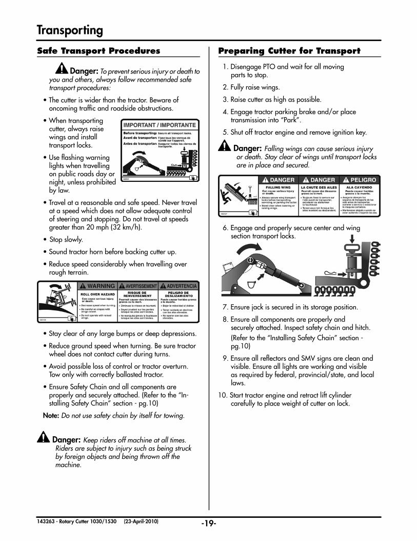
6. Engage and properly secure center and wing section transport locks.
7. Ensure jack is secured in its storage position.
8. Ensure all components are properly and securely attached. Inspect safety chain and hitch.
(Refer to the “Installing Safety Chain” section - pg.10)
9. Ensure all reflectors and SMV signs are clean and visible. Ensure all lights are working and visible as required by federal, provincial/state, and local laws.
10. Start tractor engine and retract lift cylinder carefully to place weight of cutter on lock.
Preparing Cutter for Transport
Transporting
Danger: To prevent serious injury or death to you and others, always follow recommended safe
transport procedures:
• The cutter is wider than the tractor. Beware of oncoming traffic and roadside obstructions.
• When transporting cutter, always raise
wings and install transport locks.
• Use flashing warning lights when travelling on public roads day or night, unless prohibited by law.
• Travel at a reasonable and safe speed. Never travel at a speed which does not allow adequate control of steering and stopping. Do not travel at speeds greater than 20 mph (32 km/h).
• Stop slowly.
• Sound tractor horn before backing cutter up.
• Reduce speed considerably when travelling over rough terrain.
• Stay clear of any large bumps or deep depressions.
• Reduce ground speed when turning. Be sure tractor wheel does not contact cutter during turns.
• Avoid possible loss of control or tractor overturn. Tow only with correctly ballasted tractor.
• Ensure Safety Chain and all components are properly and securely attached. (Refer to the “In-
stalling Safety Chain” section - pg.10)
Note: Do not use safety chain by itself for towing.
Danger: Keep riders off machine at all times. Riders are subject to injury such as being struck by foreign objects and being thrown off the
machine.
Safe Transport Procedures
-20-143263 - Rotary Cutter 1030/1530 (23-April-2010)
Transporting
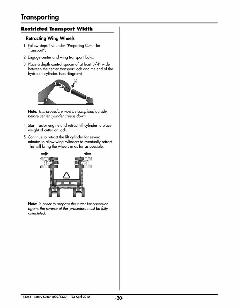
Retracting Wing Wheels1. Follow steps 1-5 under “Preparing Cutter for Transport”.
2. Engage center and wing transport locks.
3. Place a depth control spacer of at least 3/4” wide between the center transport lock and the end of the hydraulic cylinder. (see diagram)
Note: This procedure must be completed quickly, before center cylinder creeps down.
4. Start tractor engine and retract lift cylinder to place weight of cutter on lock.
5. Continue to retract the lift cylinder for several minutes to allow wing cylinders to eventually retract.
This will bring the wheels in as far as possible.
Note: In order to prepare the cutter for operation again, the reverse of this procedure must be fully completed.
Restricted Transport Width

Outer Clutch Band
-21-143263 - Rotary Cutter 1030/1530 (23-April-2010)
Troubleshooting
This section of the troubleshooting deals with someof the more frequently asked questions relating tothe general operation or performance of the Rotary Cutter. We have found that most problems are related to overlooked or neglected cutter adjustments. You may wish to review the section on “How To Set Your Cutter” (pg. 11-14) after reading this troubleshooting section.
1. Is the Rotary Cutter the correct PTO speed for your tractor?
Check the decal on the hitch of the cutter.
• 540 RPM • 1000 RPM
2. Are you cutting in the direction the Rotary Cutter was designed to cut?
This is a directional cutter. Check the center section arrow to verify:
• Against Traffic: Counter-clockwise rotation (drive on the left hand side facing oncoming traffic).
• With Traffic: Clockwise rotation (drive on the right hand side in the same direction as traffic).
3. Are the blades rotating the right direction?
Check the decals on the top of the deck for each section, and verify rotation. (There are clockwiseand counterclockwise blades, match the bladeto the rotation).
4. How fast are you cutting?
Try slowing down. (In tall, wet or dense conditions, ground speed must be reduced due to the volumeof material in the cutting chamber).
5. How high are you cutting?
• For short, dry or sparse vegetation: The lower you cut, the more suction there is and the closer you are to the stiffer base of the plant stalk. (Avoid cutting too low in rocky or uneven terrain).
• For tall, lush or dense vegetation: Cut slightly higher or reduce ground speed to avoid overloading the cutting chamber.
6. Are the blades bent?
Compare to a new blade. (Bent blades will cause loss of suction and uneven cutting height).
7. Are the blades badly worn or damaged?
Check or compare to a new blade.
8. Have you checked that the clutches are fully engaged? (Bondioli & Pavesi Driveline Models)
These clutches have a built in system to release the pressure on the linings for long storage periods to prevent them from becoming seized. Check that the 4 socket head screws on the clutches are loose. (If they are tightened all the way in the clutches will slip). Refer to the “Driveline Clutch Adjustment” section (pg. 14) for proper clutch adjustment.
9. Are the clutches slipping?
Although these clutches are non-adjustable they should be checked periodically to ensure they are set properly. The clutches will slip at a pre-determined torque setting if they are properly maintained.
To check that the clutch is properly set, make sure the tractor is shut off and all parts have stopped moving. Grasp the smooth outer clutch band with your hand and try to rotate it. It should rotate slightly.
10. Is the cutter leaving one or two uncut strips visible the next day?
This is usually caused by the tractor wheels bending over the stalks of vegetation. The cutter cannot pull them back up again soon enough to completely cut them. Cut debris is distributed on top of the bent over stalk to appear as though it is cut. By the next day the stalk stands back up again.
To minimize this:
• Reduce ground speed. (Slowing down allows more time for the material to lift and more blade passes).
• Lower the cutting height to increase suction and pick up more of the wheel tracks.
• Check that blades are not bent. Compare to a new blade. (Bent blades will cause loss of suction).
General Operation - Poor Cutting

-22-143263 - Rotary Cutter 1030/1530 (23-April-2010)
OperationSymptom Problem Solution
Uneven Cut Excessive ground speed. Reduce ground speed.
Blades worn, dull, or bent. Replace blades. (Refer to “Maintenance” section)
Cutter not level side to side. Adjust. (Refer to” Cutter Adjustments” section)
Improper height adjustment. Adjust cutter height. (Refer to “Cutter Adjustments” section)
Low tractor tire pressure on one side. Adjust tire pressure. (Refer to your tractor operator’s manual)
Turning too fast. Reduce ground speed when turning.
Tractor tires push grass down. Adjust your tractor wheel spacing. (Refer to your tractor operator’s manual)
Conditions too wet. Wait for conditions to dry.
Damaged cutter pan. Repair or replace as necessary.
Uncut Material Excessive ground speed. Reduce ground speed.
RPM too low. Use full PTO speed. (Refer to your tractor operator’s manual)
Improper blade for direction of cut. Install blades so rotation is correct.
Poor Shredding Excessive ground speed. Raise the front of cutter relative to the rear to hold and circulate material longer. (Refer to the ”How to Set Your Cutter” section - Levelling Front to Back)
Reduce ground speed.
Cutting too high. Lower cutting height. (Refer to the ”How to Set Your Cutter”section - Setting Cutting Depth)
Windrowing or Uneven Material Distribution
Material heavy and lush. Raise the front of cutter relative to the rear. (Refer to the ”How to Set Your Cutter” section - Levelling Front to Back)
Reduce ground speed.
Cutter Vibration Loose blades. Tighten blade bolts.
One new and one old blade on same cutter pan.
Replace blades in pairs.
One broken blade. Replace blades in pairs.
Broken or defective U-joint cross bearing. Repair or replace as necessary.
Driveline bent or damaged. Repair or replace as necessary.
Bent or damaged PTO shaft or CV. Repair or replace as necessary.
Bent or damaged Gearbox output shaft. Repair or replace as necessary.
Cutter pan bent or damaged. Repair or replace as necessary.
Troubleshooting

-23-143263 - Rotary Cutter 1030/1530 (23-April-2010)
BladesSymptom Problem Solution
Excessive Wear Cutting too low in abrasive conditions. (ex. sandy or rocky)
Increase cutting height.
Bolt Loosening Inadequate torque on blade bolts. Tighten blade bolts. (Refer to “Maintenance” section)
Lock nut worn out. Replace lock nut.
Cutting in very wet conditions. Do not operate in these conditions.
Cutting too low, scalping ground. Increase cutting height.
Cutting too low in rocky conditions. Increase cutting height.
Breakage Cutting too low in rocky conditions. Increase cutting height.
Cutting with damaged or extremely worn blades.
Replace blades. (Refer to “Maintenance” section)
Gear BoxesSymptom Problem Solution
Shafts and Gears Break
Slip clutch seized caused driveline to receive high shock loads.
Inspect clutch lining and repair or replace as necessary. (Refer to “Maintenance” section)
Cutting in extremely rocky conditions. Increase cutting height.
Avoid hitting large, solid objects.
Oil Seal at Blade Pan Leaks
Operating with grass or wire wrapped on shaft in seal area.
Check seal areas regularly and clean off material.
Worn seal. Replace seal.
Bent or damaged output shaft and/or bearings.
Repair or replace as necessary.
Removing blade pan using heat can dam-age seal.
Replace seal. Suggest use of puller at next removal of blade holder.
Oil Seal Leaks Worn seal. Replace seal.
Gear case overfilled. Fill only to ”FULL” line on dipstick
Gear case not vented. Check that the vent on the dipstick plug is clear.
Troubleshooting

-24-143263 - Rotary Cutter 1030/1530 (23-April-2010)
Driveline ClutchesSymptom Problem Solution
Overheated Clutch slipping. Check for jammed blade or foreign object.
Friction plates worn. Replace plates. (Refer to “Maintenance” section)
Excessive ground speed in heavyconditions.
Reduce ground speed.
Excessive scalping. Adjust cutting height. (Refer to ”Cutter Adjustments” section)
Seized Prolonged storage in damp conditions. Free up slip clutch. (Refer to “Maintenance” section)
Inspect clutch lining and repair or replace as necessary. (Refer to “Maintenance” section)
DrivelinesSymptom Problem Solution
Telescoping tube fails Shock load. Avoid solid objects.
Telescoping tube wears.
Lack of lubrication. Apply grease daily. (Refer to “Maintenance” section)
Yoke or cross fails. Lack of lubrication. Apply grease daily. (Refer to “Maintenance” section)
Shock load. Avoid solid objects.
Slip clutch seized caused driveline to receive high shock loads.
Inspect clutch lining and repair or replace as necessary. (Refer to “Maintenance” section)
Twisted Slip clutch seized caused driveline to receive high shock loads.
Inspect clutch lining and repair or replace as necessary. (Refer to “Maintenance” section)
Constant Velocity Joint Fails
Lack of lubrication. Apply grease as described in the ”Maintenance” Section.
Turning too sharp. Avoid extremely sharp turns and jackknifing.
PTO Driveline Bent Contact with drawbar. Reposition drawbar. (Refer to “How to Set Your Tractor” Section)
Driveline too long, bottoms outs when operating through deepgullies.
Avoid these conditions.
Troubleshooting

-25-143263 - Rotary Cutter 1030/1530 (23-April-2010)
Danger: To prevent serious injury or death to you or others, and to prevent damage to your
equipment, always follow these safety messages:
• To prevent personal injury from unexpected movement, ensure cutter is properly supported and on a level surface before performing any service work.
• Do not make or allow any alterations or modifications to this rotary cutter, its components, or its functions.
• Never lubricate, adjust, or service machine while it is moving. Ensure tractor engine is off, all moving parts have stopped, and the PTO driveline has been disconnected before servicing.
• The blades and cutter pan may rotate for several minutes after PTO is shut off. Before working on
cutter, look and listen for rotating driveline to stop completely.
• Always secure wing transport locks before servicing, parking, or transporting cutter. Always keep people a safe distance from the cutter
when raising or lowering wings.
• Ensure all guards, shielding, and their components are maintained and in proper working condition. Replace or repair any damaged components.
• Ensure all guards, shielding, and their components are replaced and secured after service is complete.
• Maintain the product safety decals and replace any decals that are damaged, missing or unreadable.
Before adjusting or servicing a cutter connected toa tractor:
1. Park cutter and tractor on level ground.
2. Engage tractor parking brake and/or place transmission into “Park”.
3. Disengage PTO.
Wings Up
4. Raise cutter and wing(s).
5. Engage center and wing transport locks.
Wings Down
4. Raise cutter and engage center transport lock.
5. Lower wings completely.
6. Shut off tractor engine and remove ignition key.
7. Place safety stands in secure locations under center body and wing sections, NOT under axles or wheel supports.
8. Start tractor engine and raise cutter.
9. Disengage center transport lock and lower cutter onto stands.
10. Engage tractor parking brake and/or place transmission into “Park”.
11. Relieve pressure in hydraulic system. (See tractor Operator’s Manual).
12. Shut off tractor engine and remove ignition key.
13. Ensure all moving parts have stopped, then remove PTO driveline from tractor.
Maintenance & ServiceSafe Maintenance Procedures

8h8h
8h
4h
8h
8h
Hitch Components
Tiebar Pins
Hitch Pivot Pins 8h
8h
8h
Walking Axle Suspension bolts
Tiebar Pins8h
8h
-26-143263 - Rotary Cutter 1030/1530 (23-April-2010)
• Clean off deck and gearboxes of debris at the end of every day.
Note: Build up of debris may
interfere with driveline and cause gearboxes to overheat resulting in damaged components.
Also a build of wet debris may result in corrosion.
Important: It is very important to grease the constant velocity body of the PTO driveline with a minimum of 30 shots of grease every 4 hrs.
Caution: The CV body serves as a reservoir for the lubrication of
the centering mechanism. Failure
to lubricate may result in machine damage.
• Visually inspect machine for damage. Repair or replace damaged parts as required.
• Visually inspect all cutter blades for damage. Repair or replace damaged blades or blade hardware as required.
• Fully inspect all cutter blades for chips, cracks, wear, and abnormal bends. Damaged blades can cause serious injury or death.
• Fully inspect all blade hardware and ensure they are all properly tightened and secured.
• Check the tightness of all newly replaced nuts and bolts after the first 8 hours of operation, then weekly.
• Grease all driveline components.
• Check all hardware to ensure they are tight and secure.
Maintenance & Service
• Grease all hitch components, tiebar pins, and walking axle suspension bolts.
4 Hour
8 Hour (Daily)

Recommendedtire pressure
42 psi
Walking Axle Bushing
20h
Cylinder Pins20h
Wing Strut Bolts
20h
Hitch Tongue Pivot Torque to 75 lb.ft
Suspension Pivot Bolt Torque to 180-200 lb.ft.
Front Skid Shoes
-27-143263 - Rotary Cutter 1030/1530 (23-April-2010)
• Grease all axle hub bearings.
• Check tire pressures if using aircraft tires.
• Check skid shoes for excessive wear.
Note: Wing skid shoes can be switched from corner to corner. (1530 Model)
• Pull apart the driveline universal slider shafts and apply grease to all sides.
• Re-torque suspension pivot bolts to 180-200 lb.ft. If too tight or too loose it could cause excessive wear.
• Retorque hitch tongue pivot bolt to 75 lb.ft. If too tight or too loose it could cause excessive wear.
Maintenance & Service
Caution: A consistent loss of fluid can indicate damaged seals. Damaged seals should be replaced immediately to prevent ruining the gearbox.
• Check fluid levels on all gearboxes (on level ground)
When Checking/Filling:
20 Hour
100 Hour
50 Hour
• Check the condition of lock pins, cotter pins, and all other fasteners weekly. Replace if necessary.
• Grease all cylinder pins, walking axle bushings, rockshaft pins, and wing strut pins.
Fill line
Output (Wing & Center) Gearboxes
OMNI Gear Models
• Use SAE 80w/90 Gear Oil
• A sight glass is located on middle of the output gearboxes. Fill until fluid reaches the center of the sight glass.
Bondioli & Pavesi Models • Use SAE 80w/90 Gear Oil
• The dipstick is located on the vent plug. To get a proper reading when checking oil level, do not screw in the dipstick. Fill until oil reaches the dipstick fill line.
Splitter Gearboxes - OMNI & Bondioli Models
• Use SAE 80w/90 Gear Oil
• Use fluid level plug on splitter box to check level. To get a proper reading when checking oil level, do not screw in the dipstick. Fill until oil reaches the dipstick fill line.
• Replace the fluid in new gearboxes after the initial 50 hours of use. Then continue to replace the fluid annually.
Note: Before checking level on dipstick Wait approximately 15-20 min. after filling right angle gearboxes to allow fluid to settle into the bottom cavity before checking level on dipstick.
• Check hubs for bearing play and condition of seal.
• Check gearbox bolts. Re-torque if necessary.
• Re-torque driveline yoke bolts: (Refer to pages 55-56 for proper
torque values)
• Re-torque precision hitch bolt to 600 lb.ft (814 N.m).

Suspension spring & bolt
Suspension pivot bolt.
Walking axle spacer & bearing.
Hitch TonguePivot Bolt
Suspension spring & bolt
Exposed thread length.
Walking axle pivot bolt.
-28-143263 - Rotary Cutter 1030/1530 (23-April-2010)
• It is recommended that hubs are dismantled, cleaned, inspected, and repacked every year. Whenever a worn or damaged seal is
replaced it is also recommended that the bearing assembly be cleaned and repacked
with wheel grease.
• Check all gearbox seals for leaks. Replace as required.
• Replace fluids in all gearboxes.
Caution: If the universal joint sliding members are allowed to dry out to the point where the two halves cannot slip freely, damage to the rotary cutter or tractor may
result.
• Pull apart the driveline universal slider shafts and apply grease to all sides.
• The shielding on the drivelines should be re-moved and the old grease should be removed with a solvent.
Note: Follow the above procedure morefrequently in dirty or dusty conditions.
Warning: High pressure fluid can pierce skin causing serious injury or death. Relieve pressure on system before repairing or adjusting. Wear proper hand and eye protection when searching for leaks. Use
wood or cardboard instead of hands. Keep all components in good repair.
• Inspect all hydraulic hoses for cracks, wear, and leaks.
• Remove hitch tongue pivot bolt, clean & inspect, turn 180
degrees to change wear surface, and
re-insert. Replace if worn. Torque to 75 lb.ft.
• Disassemble precision hitch components (if applicable), clean, inspect, and reassemble.
Maintenance & ServiceAnnually
• Inspect suspension springs and bolts. Replace
if damaged.
• Inspect walking axle bushings and bearings. Replace if worn. Remove pin, turn 180 degrees
(to change wear surface), and replace.
• Inspect suspension and walking axle pivot bolts. Replace if worn.
Remove, turn (to change wear surface), and replace.
Torque to 180-200 lb.ft.
Typical Suspension DetailPreloading of rubber spring is required on all strut assemblies. Exposed thread length when usingcorrect hardware should be approximately: • 3/8” on wing strut assemblies
• 1/2” on the center section rockshaft strut assemblies.

High Suction Blade
Skid Pan(Optional)
Blade Flat Washer Blade Locknut Torque to 725 lb.ft
Cotter PinPan Support Bar
Coned Washer
Nut Access Hole
Torque Castle Nut to 800 lb.ft
Nut Access Hole
SupportBolt& Blade
Blade Bolt
Torque Blade Locknut to 725 lb.ft
High Suction Blade
Blade Carrier(Standard)
Square Blade Bolt
-29-143263 - Rotary Cutter 1030/1530 (23-April-2010)
Maintenance & Service
Danger: The blades and cutter pan may rotate for several minutes after PTO is shut off. Before working on cutter, look and listen for rotating driveline to stop completely.
• Blades should be inspected daily for chips, cracks, wear, and abnormal bends. Damaged blades can cause serious injury or death.
• Do not try to modify blades in any way such as sharpening, welding, or straightening. Modifying the blades may reduce the strength of the blade, increasing the risk of broken pieces being thrown from the machine.
• If the blades are dull, bent, worn, chipped, or cracked, replace them in pairs with genuine
Degelman blades only.
• Always replace damaged blades in pairs. Unbalanced blades are dangerous and machine damage may result.
• Retighten blade mounting hardware daily. Blade hardware should be torqued to 725 lb-ft.
• It is recommended to change blade bolts and locknuts every time the blades are replaced.
• Seat bolt flush against pan with hammer before tightening nut.
• When changing blades with only one person you may wish to support the blade and hex bolt from below to make it easier to tighten the blade locknut from above.
Blades
Blade Hardware
Blade Carrier (or optional Skid Pan)
• Blade Carriers (Skid Pans) are secured with castle nuts and cotter pins to the splined shaft on the gearboxes. A coned washer is located between the castle nut and the gearbox shaft. The coned part of the washer should be positioned against the nut.
• It is important to periodically check and retighten the retaining (castle) nut.
• It is important to torque the nut to 800 lb.ft.
Caution: To prevent personal injury from falling pan, it is important to put blocks under cutter pan when removing retaining nuts.
• Blade carriers (Skid Pans) should be removed from the top side by hitting the carrier or pan support bar
through the nut access hole on the top deck. When hitting carrier or pan support bar, you
should rotate it 180 degrees between hits.

TORQUE
all hardware
Maintenance & ServiceTorque Specifications
Maintenance Notes
CHECKING BOLT TORQUE
The tables shown below give correct torque values for various bolts and capscrews. Tighten all bolts to the torques specified in chart unless otherwise noted. Check tightness of bolts periodically, using bolt torque chart as a guide. Replace hardware with the same strength (Grade/Class) bolt.
IMPERIAL TORQUE SPECIFICATIONS(based on “Zinc Plated” values)
SAE-5 SAE-8
Size Grade 5 Grade 8 lb.ft (N.m) lb.ft (N.m) 1/4” 7 (10) 10 (14) 5/16” 15 (20) 20 (28) 3/8” 25 (35) 35 (50) 7/16” 40 (55) 60 (80) 1/2” 65 (90) 90 (120) 9/16” 90 (125) 130 (175) 5/8” 130 (175) 180 (245) 3/4” 230 (310) 320 (435) 7/8” 365 (495) 515 (700) 1” 550 (745) 770 (1050) 1-1/8” 675 (915) 1095 (1485) 1-1/4” 950 (1290) 1545 (2095) 1-3/8” 1250 (1695) 2025 (2745) 1-1/2” 1650 (2245) 2690 (3645)
METRIC TORQUE SPECIFICATIONS(based on “Zinc Plated” values)
8.8 10.9
Size Class 8.8 Class 10.9 lb.ft (N.m) lb.ft (N.m) M6 7 (10) 10 (14) M8 16 (22) 23 (31) M10 30 (42) 45 (60) M12 55 (75) 80 (108) M14 90 (120) 125 (170) M16 135 (185) 195 (265) M18 190 (255) 270 (365) M20 265 (360) 380 (515) M22 365 (495) 520 (705) M24 460 (625) 660 (895) M27 675 (915) 970 (1315) M30 915 (1240) 1310 (1780) M33 1250 (1695) 1785 (2420) M36 1600 (2175) 2290 (3110)
HYDRAULIC FITTING TORQUE
Tightening Flare Type Tube Fittings
1. Check flare and flare seat for defects that might cause leakage.
2. Align tube with fitting before tightening.
3. Lubricate connection and hand tighten swivel nut until snug.
4. To prevent twisting the tube(s), use two wrenches. Place one wrench on the connector body and with the second tighten the swivel nut to the torque shown.
Hydraulic Fitting Torque* Size lb.ft (N.m) 1/2 34 (46) 3/4 75 (100) 7/8 90 (122)
* The torque values shown are based on lubricated connections as in reassembly.
-30-143263 - Rotary Cutter 1030/1530 (23-Aug-2016)

Taper Pin
Band
Spring
Thrust Plate
Friction Lining
Friction Lining
Friction Lining
Friction Lining
Bolt
Nut
Flange Yoke
Lining Plate
Torque Limiter Plate
Hub
Bushing
Spring DishesInward
-31-143263 - Rotary Cutter 1030/1530 (23-April-2010)
Each of the drivelines coming off the splitter gear box is equipped with a friction disc torque limiter to reduce possibility of machine damage. The torque value of each slip clutch (in N.m) is stamped on the face of the flange yoke.
Disassembly and Inspection1. Remove taper pin.
2. Loosen the bolts evenly and progressively to uniformly reduce the spring load (i.e. do not
remove each nut completely in sequence).
3. Fully disassemble the clutch and inspect the condition of all the components. New friction linings
are 3.2mm thick, if friction linings are worn below 2.5mm, replacement is recommended. (Replacement part numbers can be found in the parts section of the manual.) Use brake cleaner and a wire brush as required, to clean the metal contact surfaces. Do not grind or excessively score the surfaces.
4. Inspect hardware and replace as required.
Maintenance & Service
Assembly1. Assemble the parts as shown in the diagram starting
by inserting the bushing into the flange yoke. Avoid grease or oil on any of the surfaces.
2. Install the bolts and tighten the nuts until they contact the spring. Note: Inspect hardware and replace as required.
3. Tighten the bolts uniformly in order to compress the spring evenly until the band is firmly tightened between the flange yoke and spring.
4. Loosen off each bolt 1/4 turn to set the spring compression to the proper height and torque setting.
The spacer band should rotate slightly.
5. Re-insert taper pin into the hub.
6. With tractor at idle speed, engage PTO for 2-3 seconds to make the clutch slip. After new linings are installed, the torque setting will be low until the linings “seat” against the metal plates. After the first few slips, the torque should rise to the normal setting.
Do not allow the clutch to slip for more than 2-3 seconds at a time to prevent damage to the lining.
If the clutch does not slip, repeat the procedure 2 or 3 times.
7. Using the hex wrench provided, fully loosen all four of the socket head screws. They will not unscrew completely out of the clutch. This will restore
pressure to the linings for proper operation.
The clutch is now ready for use. At the end of the season, or before any long period of non-use, fully tighten the socket head screws to relieve pressure on the linings. For best performance, keep the clutch in a dry place to help prevent sticking.
Torque Limiter - Bondioli & Pavesi

-32-143263 - Rotary Cutter 1030/1530 (23-April-2010)
Maintenance & Service
Torque Limiter Run In & RepairTools Required: 1/2” or M13 box wrench or socket
Run-In of the Friction Clutch (Necessary for all new clutches and clutches that
have not been operated for (1) season or approxi-mately 60 days.)
1. Make sure the tractor is off and the PTO is disen-gaged.
2. Disconnect the driveline from the tractor.
3. Locate the long bolts on the O.D. of the clutch pak. Loosen the bolts until all are finger tight, then
tighten each one half a turn.
4. Attach the implement to the tractor and the driveline to the tractor PTO. Stand clear.
5. Turn the tractor on. Engage the PTO clutch and run for a few seconds, or until the clutch visibly smokes, then disengage the PTO.
6. Make sure the tractor is off and the PTO is disen-gaged.
7. Disconnect the driveline from the tractor.
8. Tighten the long bolts on the O.D. of the clutch pak until the compression plate is in full contact with the housing.
9. Grease the fitting on the yoke using Shell Super Duty or an equivalent lithium grease.
Repair And RebuildingDisassembly
1. Place the clutch and universal joint assembly on a bench, with the end of the clutch accessible.
2. Remove the long bolts on the outside of the housing that hold the friction pack together.
3. Remove the plate(s) and all internal components, leaving the yoke/hub intact.
4. Discard the friction discs if worn below 1/16”.
Inspection
6. Inspect the steel and iron parts for wear, warpage or cracking and replace if necessary.
7. Inspect the yoke/hub for looseness. If there is more than .03 end play, replace.
8. Clean any, rust or dust from the plate surfaces with a wire brush or steel wool.
Assembly
9. Place one new friction disc inside the housing, then the separator plate, then the other friction disc.
10. Add the pressure plate so that the flat surface rests on the friction disc (the tangs on the plate must fall into the reliefs in the housing).
11. Add the disc spring so that the spring inside diam-eter contacts the fins of the pressure plate.
12. Assemble the compression plate and all long bolts, making sure that all nuts are in their pockets. Tighten all long bolts to 30 ft-lbs.
Torque Limiter - Weasler
Housing
Yoke & Hub
Separator Plate
Friction Disc
Pressure Plate
Spring Disc
Compression Plate
Long Bolt
Nut
Short Bolt
Friction Disc
*IMPORTANT*Assemble small diameter
(I.D.) of spring against fins of pressure plate.
-33-143263 - Rotary Cutter 1030/1530 (23-April-2010)
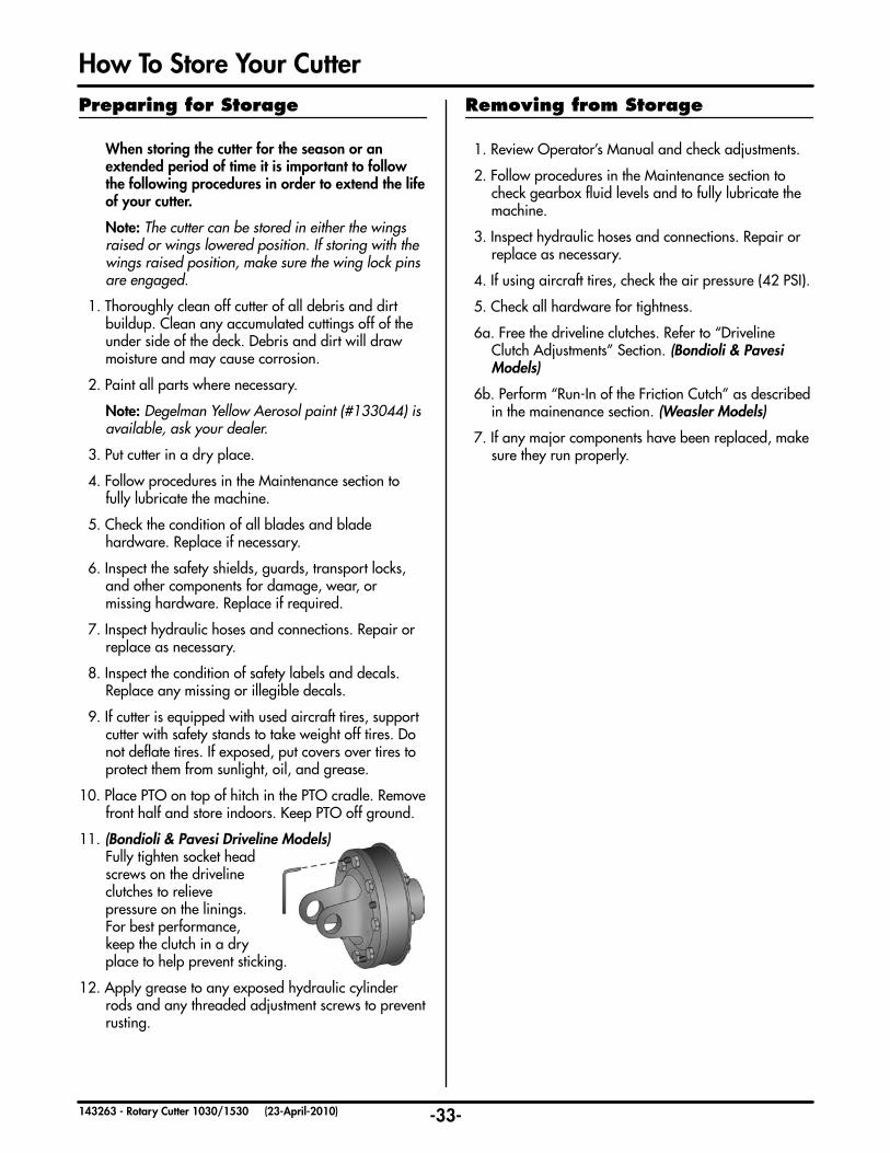
When storing the cutter for the season or an extended period of time it is important to follow the following procedures in order to extend the life of your cutter.
Note: The cutter can be stored in either the wings raised or wings lowered position. If storing with the wings raised position, make sure the wing lock pins are engaged.
1. Thoroughly clean off cutter of all debris and dirt buildup. Clean any accumulated cuttings off of the under side of the deck. Debris and dirt will draw moisture and may cause corrosion.
2. Paint all parts where necessary.
Note: Degelman Yellow Aerosol paint (#133044) is available, ask your dealer.
3. Put cutter in a dry place.
4. Follow procedures in the Maintenance section to fully lubricate the machine.
5. Check the condition of all blades and blade hardware. Replace if necessary.
6. Inspect the safety shields, guards, transport locks, and other components for damage, wear, or
missing hardware. Replace if required.
7. Inspect hydraulic hoses and connections. Repair or replace as necessary.
8. Inspect the condition of safety labels and decals. Replace any missing or illegible decals.
9. If cutter is equipped with used aircraft tires, support cutter with safety stands to take weight off tires. Do not deflate tires. If exposed, put covers over tires to protect them from sunlight, oil, and grease.
10. Place PTO on top of hitch in the PTO cradle. Remove front half and store indoors. Keep PTO off ground.
11. (Bondioli & Pavesi Driveline Models) Fully tighten socket head
screws on the driveline clutches to relieve
pressure on the linings. For best performance, keep the clutch in a dry place to help prevent sticking.
12. Apply grease to any exposed hydraulic cylinder rods and any threaded adjustment screws to prevent rusting.
How To Store Your Cutter
1. Review Operator’s Manual and check adjustments.
2. Follow procedures in the Maintenance section to check gearbox fluid levels and to fully lubricate the machine.
3. Inspect hydraulic hoses and connections. Repair or replace as necessary.
4. If using aircraft tires, check the air pressure (42 PSI).
5. Check all hardware for tightness.
6a. Free the driveline clutches. Refer to “Driveline Clutch Adjustments” Section. (Bondioli & Pavesi Models)
6b. Perform “Run-In of the Friction Cutch” as described in the mainenance section. (Weasler Models)
7. If any major components have been replaced, make sure they run properly.
Preparing for Storage Removing from Storage

Mounting Brackets
Shredder Blade
Shredder Bolt
Lock Nut
-34-143263 - Rotary Cutter 1030/1530 (23-Aug-2016)
Attachments / Accessories
131384 Recapped foam filled
131385 Recapped air filled (pneumatic)
501541 Shredder Blade Kit -bidirectional (for OMNI and B&P blade carriers)
501533 Light Kit - (mounting brackets included)
501535 Tow Hitch
500335 Clevis Hitch
501536 Toolbox - (mounting brackets included)
Light Kit
Tow Hitch
Clevis Hitch
Toolbox & Blade Storage Kit
Shredder Blade Kit
Aircraft Tires (22 x 6.6)
501580 Wing Guide Wheel - RH (shown)501581 Wing Guide Wheel - LH
Guide Wheel

A
B (B)
C
D
B (B)A (A)
Lifting Left Wing (Lifting Right Wing)
Pulley Block
Winch Tower
Wing Lift BracketsClevis Hook
Winch
Cable
-35-143263 - Rotary Cutter 1030/1530 (23-April-2010)
The winch should only be used when the hydraulic wing lift is disabled. The winch is designed to lift only one wing at a time. A pulley block is used to reduce the amount of effort required to crank the winch handle to lift the wing. The winch must always be used with the pulley block. A wing lift bracket needs to be added to each wing cylinder lug prior to operation. These are included with the winch kit.
Danger: Never, at any time, walk near or under the wing while it is being raised until safely secured with the wing transport lock pin. Never allow bystanders near the wing until it is safely secured.
Note: The standard wing lift is a single acting hydraulic cylinder, if this is the case,
the hydraulic cylinder may be left attached to the wing. If the rotary cutter is equipped with a double acting hydraulic cylinder, the hydraulic cylinder should be removed and placed on the deck.
Attachments / AccessoriesOperation:
• Unhook the clevis hook and pulley block from their storage location on the winch tower.
• Unwind the winch using the crank handle with one hand, while assisting the cable off the spool with the other hand. Try to keep a slight tension on the cable as it unwinds.
• The pulley block has a bolt at one end, slide the bolt into the slot (A) on the wing lift lug and hook the clevis hook end up to the lug on the winch tower (B).
• Crank the handle to get all the slack out of the cable. Re-check that the clevis hook is secure and that the pulley and cable are free to move as required. Crank the winch handle (C) to raise the wing.
Note: The winch is equipped with an automatic brake while cranking under load. This takes some effort to overcome.
• When the wing is all the way up, engage the wing transport safety lock pin (D).
• Slowly turn the crank the opposite direction to let the wing down onto the
transport lock pin.
• Unhook the cable and pulley block and repeat the same procedure on the other wing if necessary.
• Replace the pulley block and clevis hook back into their storage location on the winch tower. Make sure to keep tension on the cable as it is wound back onto the spool.
Note: To lower the wing, reverse this procedure.
501534 Manual Wing Winch Kit
Winch kit
Winch Operation

-36-143263 - Rotary Cutter 1030/1530 (23-April-2010)

-37-143263 - Rotary Cutter 1030/1530 (23-April-2010)

-40-143263 - Rotary Cutter 1030/1530 (23-April-2010)
Parts
Right Wing Assembly (pg. 43)Wing Driveline (pg. 55-56)
Rephasing Cylinder, 3” x 8” (pg. 54)Wing Lift Cylinder, 3” x 16” (pg. 53)
Right Wheel Strut (Walking Axlealso available) (pg. 48)
Rockshaft Assembly(pg. 47)
Center Section Assembly(pg. 41-42)
Center Shield Assembly(pg. 46)
Hitch Assembly (pg. 45)
Main Driveline(pg. 55-56)
Left Wing Assembly(pg. 43)
Left Wheel Strut (Walking Axlealso available)(pg. 48)
Rephasing Cylinder,3-1/4” x 8”(pg. 54)
Wing Driveline (pg. 55-56)
Tie Bar Assembly (pg. 41)
Center Driveline (pg. 55-56)
Rephasing Cylinder, 3-1/2” x 8”(pg. 53)
Right Wheel Strut (Walking Axlealso available) (pg. 48)
Rockshaft Assembly(pg. 47)
Hitch Assembly (pg. 45)
Main Driveline(pg. 55-58)
CounterweightAssembly (pg. 44)
Right Wing Assembly (pg. 43)Wing Driveline (pg. 55-56)
Rephasing Cylinder, 3-1/4” x 8” (pg. 54)Wing Lift Cylinder, 3” x 16” (pg. 53)
Rephasing Cylinder, 3-1/2” x 8”(pg. 53)
Center Section Assembly(pg. 41-42)
Center Shield Assembly(pg. 46)
Tie Bar Assembly (pg. 41)
General Assembly - 1530 Model
General Assembly - 1030 Model
Pan, Blades, & Hardware (pg. 50)
Pan, Blades, & Hardware (pg. 50)
Wheels, Hubs & Spindles (pg. 49)
Wheels, Hubs & Spindles (pg. 49)
Center Driveline (pg. 55-56)
Gearbox Overview found on page 68
Driveline Overview found on pages 55-56
Gearbox Overview found on page 68
Driveline Overview found on pages 55-56
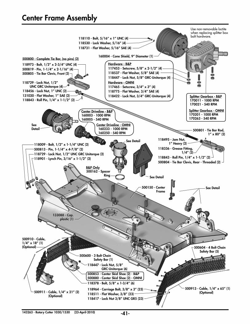
118731 - Flat Washer, 5/16” SAE (4)
133088 - Cap, plastic (1)
Use non-removable loctite when replacing splitter box bolt hardware.
-41-143263 - Rotary Cutter 1030/1530 (23-April-2010)
Center Frame Assembly
160004 - Cone Shield, 9” Diameter (1)
118378 - Bolt, 5/8” x 1-3/4” (6)
118447 - Lock Nut, 5/8”GRC-Unitorque (6)
500853 - Center Skid Shoe (2) - B&P
500600 - 3 Bolt Chain Safety Bar (1)
500604 - 4 Bolt Chain Safety Bar (5)
500813 - Pin, 1-1/4” x 4-7/8” (2)118729 - Lock Nut, 1/2” UNC GRC Unitorque (2)118901 - Lynch Pin, 3/16” x 1-1/2” (2)
118009 - Bolt, 1/2” x 1-1/4” UNC (2)
SeeDetail
See Detail
See Detail
500910 - Cable, 1/4” x 18” (1)(Optional)
500911 - Cable, 1/4” x 21” (2) (Optional)
500913 - Cable, 1/4” x 65” (1) (Optional)
500150 - Center Frame
500162 - Spacer Ring
500801 - Tie Bar Rod, 1” x 80” (2)
118843 - Roll Pin, 1/4” x 1-1/2” (2)
118495 - Jam Nut, 1” Heavy (2)
500804 - Tie Bar Clevis, Rear - Threaded (2)
118336 - Grease Fitting, 1/4” (2)
See Detail
B&P Only
118964 - Carriage Bolt, 3/8” x 3” (23)118511 - Flat Washer, 3/8” (23)118417 - Lock Nut 3/8” UNC GR5 (23)
500805 - Tie Bar Clevis, Front (2)
118456 - Lock Nut, 1” UNC (2)131020 - Flat Washer, 1” SAE (2)
118973 - Bolt, 1/2” x 2-3/4” UNC (4)500819 - Pin, 1-1/4” x 2-1/16” (4)
118729 - Lock Nut, 1/2”UNC GRC Unitorque (4)
500800 - Complete Tie Bar, (no pins) (2)
118843 - Roll Pin, 1/4” x 1-1/2” (2)
Center Driveline - B&P160003 - 1000 RPM160005 - 540 RPM
Center Driveline - OMNI 160233 - 1000 RPM 160250 - 540 RPM
500880 - Center Skid Shoe (2) - OMNI
118530 - Lock Washer, 5/16” (4)118110 - Bolt, 5/16” x 1” UNC (4)
Splitter Gearbox - B&P170011 - 1000 RPM170021 - 540 RPM
Splitter Gearbox - OMNI170201 - 1000 RPM170263 - 540 RPM
117453 - Setscrew, 5/8” x 2-1/2” (4)118537 - Flat Washer, 5/8” SAE (4)118447 - Lock Nut, 5/8” GRC-Unitorque (4)
Hardware - B&P
Hardware - OMNI117465 - Setscrew, 3/4” x 3” (4)118775 - Flat Washer, 3/4” SAE (4)118422 - Lock Nut, 3/4” GRC-Unitorque (4)

-42-143263 - Rotary Cutter 1030/1530 (23-April-2010)
Center Frame Assembly
118729 - Lock Nut, 1/2” GRC-Unitorque 500825 - Wing Float Link - B&P
500817 - Pin, 1-1/4” x 2-7/16” 118112 - Bolt, 1/2” x 3” UNC
117111 - Bushing, 1-1/2” OD x 1” (2)
117087 - Bushing, 1-1/4” OD x 1”
501007 - Rubber Spring 118417 - Lock Nut, 3/8” UNC
118957 - Transport Pin, 3/4” x 6”
118087 - Bolt, 3/8” x 2” UNC
118729 - Lock Nut, 1/2” GRC-Unitorque (4)500815 - Pin, 1-1/4” x 3” (4)118009 - Bolt, 1/2” x 1-1/4” UNC (4)
118830 - Hair Pin, 3/16” x 3-1/4”
118447 - Lock Nut, 5/8” GRC-Unitorque (4)143123 - Hose Holder Spring (4)118537 - Flat Washer, 5/8” SAE (4)
118024 - Bolt, 5/8” x 1-1/2” UNC (4)
500719 - Shield Bumper Plate (1)
501005 - Urethane Bumper (2)
118378 - Bolt, 5/8”x 1-3/4” (2)
118537 - Flat Washer, 5/8” SAE (2)
118982 - Bolt, M8 x .125 x 20 P8.8 (2)118556 - Lock Washer, M8 (2)118731 - Flat Washer, 5/16” SAE (2)
118901 - Lynch Pin, 3/6” x 1-1/2” (1) Counter Clockwise - B&P170063 - Gearbox 1000 RPM170017 - Gearbox 540 RPM
118983 - Bolt, 1/4” x 3/4” (4)118555 - Flat Washer, 1/4” (4)
118555 - Flat Washer, 1/4” (4)
118483 - Lock Nut, 1/4” - Unitorque (4)
500137 - Bracket (1)
133100 - Manual Holder (1)
142135 - SMV Sign (1)
118483 - Lock Nut, 1/4” - Unitorque (2)
118983 - Bolt, 1/4” x 3/4” (2)
118005 - Bolt, 3/8” x 1” UNC (2)
118417 - Lock Nut, 3/8” UNC (2)
118447 - Lock Nut, 5/8” GRC-Unitorque (2)
2 of each Req’d for 1530 Model
2 of each Req’d for 1530 Model
Counter Clockwise - OMNI170251 - Gearbox 1000 RPM170259 - Gearbox 540 RPM
Clockwise - B&P170061 - Gearbox 1000 RPM170019 - Gearbox 540 RPM
Clockwise - OMNI170253 - Gearbox 1000 RPM170261 - Gearbox 540 RPM
-OR-
500828 - Wing Float Link - OMNI
118795 - Bolt, 5/8” x 2-1/4” GR8 (6)118537 - Flat Washer, 5/8” SAE (6)118447 - Lock Nut, 5/8” GRC-Unitorque (6)
Hardware - B&P
Hardware - OMNI118048 - Bolt, 3/4” x 2-1/2” GR8 (6)118775 - Flat Washer, 3/4” SAE (6)118422 - Lock Nut, 3/4” GRC-Unitorque (6)
Hardware - B&P
Hardware - OMNI
503308 - Shield Bumper Plate (1)
117463 - Bolt, M10 x 1.5 x 20 P8.8 (2)117464 - Lock Washer, M10 (2)118511 - Flat Washer, 3/8” (2)
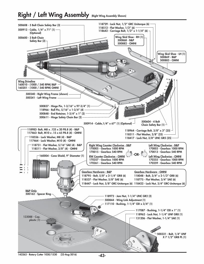
133088 - Cap, plastic (1)
500162 - Spacer RingB&P Only
-43-143263 - Rotary Cutter 1030/1530 (23-Aug-2016)
Right / Left Wing Assembly
118556 - Lock Washer, M8 (4) - B&P
118731 - Flat Washer, 5/16” SAE (4) - B&P
160004 - Cone Shield, 9” Diameter (1)
118982- Bolt, M8 x .125 x 20 P8.8 (4) - B&P
131206 - Flat Washer, 1-1/4” SAE (1)118962 - Lock Nut, 1-1/4” UNF GR8 (1)
500331 - Bolt, 1/4” UNF X 7 1/2” GR8 PL (1)
117087 - Bushing, 1-1/4” OD x 1” (1)
500844 - Wing Link Adjustment (1)117110 - Bushing, 1-1/4” OD x 3/4” (1)
118972 - Jam Nut, 1-1/4” UNC GR2 (2)
118512 - Flat Washer, 1/2” (6)118642 - Carriage Bolt, 1/2” x 1-1/4” (6)
118729 - Lock Nut, 1/2” GRC Unitorque (6)
500604 - 4 Bolt Chain Safety Bar (1)500914 - Cable,1/4” x 67” (1) (Optional)
500608 - 5 Bolt Chain Safety Bar (3)
500600 - 3 Bolt Chain Safety Bar (2)
500912 - Cable, 1/4” x 71” (1) (Optional)
(Right Wing Assembly Shown)
Wing Driveline160010 - (1000 / 540 RPM) B&P160201 - (1000 / 540 RPM) OMNI
500837 - Hinge Pin, 1-3/16” x 97-3/4” (1)118966 - Roll Pin, 5/16” x 1-3/4” (4)
500611 - Hinge Safety Chain Bar (2)
500240 - Right Wing Frame (shown)500241 - Left Wing Frame
500848 - End Retainer, 1-3/4” x 1” (2)
118964 - Carriage Bolt, 3/8” x 3” (25)118511 - Flat Washer, 3/8” (25)118417 - Lock Nut, 3/8” UNC GR5 (25)
Wing Skid Shoe - LH (1) 500869 - B&P 500883 - OMNI
Wing Skid Shoe - RH (1) 500868 - B&P 500882 - OMNI
117463- Bolt, M10 x .15 x 65 P8.8 (4) - OMNI
117464 - Lock Washer, M10 (4) - OMNI
118511 - Flat Washer, 3/8” (4) - OMNI
118795 - Bolt, 5/8” x 2-1/4” GR8 (6)
118447 - Lock Nut, 5/8” GRC-Unitorque (6)118537 - Flat Washer, 5/8” SAE (6) 118775 - Flat Washer, 3/4” SAE (6)
118422 - Lock Nut, 3/4” GRC-Unitorque (6)
118048 - Bolt, 3/4” x 2-1/2” GR8 (6)Gearbox Hardware - OMNIGearbox Hardware - B&P
Right Wing Counter Clockwise - B&P170005 - Gearbox 1000 RPM170015 - Gearbox 540 RPM
RW Counter Clockwise - OMNI170257 - Gearbox 1000 RPM170261 - Gearbox 540 RPM
Left Wing Clockwise - B&P170003 - Gearbox 1000 RPM170013 - Gearbox 540 RPM
Left Wing Clockwise - OMNI170255 - Gearbox 1000 RPM170259 - Gearbox 540 RPM
-OR-

Optional Rubber Shield Assembly501035 - Rubber Safety Shield Assembly
- includes -
118420 - Lock Nut, 1/2” UNC GR5 (2)501037 - Bolt Plate, 1/4” (1)501038 - Rubber, Safety Shield (1)
-44-143263 - Rotary Cutter 1030/1530 (23-April-2010)
Counterweight Assembly (1030 Model Only)
500837 - Hinge Pin, 1-3/16” x 97-3/4” (1)118966 - Roll Pin, 5/16” x 1-3/4” (2)
118984 - Bolt, 1-1/4” x 3” GR5 (2)500257 - Bolt Plate (2)118445 - Lock Nut, 1-1/4” GR5 (2)
117436 - Bolt, 1” x8-1/2” GR5 (6)
118011 - Bolt, 1/2” x 1-1/2” (2)
500870 - Counterweight Skid (1)-B&P500876 - Counterweight Skid (1)-OMNI
500264 - Counterweight Frame (1)
118642 - Carriage Bolt, 1/2” x 1-1/4” (10)
500868 - Wing Skid Shoe - RH (1) - B&P500882 - Wing Skid Shoe - RH (1) - OMNI
118729 - Lock Nut, 1/2” GRC Unitorque (10)
118456 - Lock Nut, 1” GR5 (6)118520 - Flat Washer, 1” (6)
118587 - Flat Washer, 1/2” F436 PL (10)
Wing Skid Shoe - LH (1)500869 - B&P500883 - OMNI
118511 - Flat Washer, 3/8” (8)
306356 - Chain, 5/16” - 11 Links (4)
118417 - Lock Nut, 3/8” UNC GR5 (4)
500260 - Weight Plate, 1” (12)
118136 - Bolt, 3/8” x 1-1/2” (4)

-45-143263 - Rotary Cutter 1030/1530 (23-April-2010)
Hitch Assembly
143111 - Hose Holder (1)
118024 - Bolt, 5/8” x 1-1/2” UNC (1)
118514 - Washer, 5/8” (1)
118447 - Lock Nut, 5/8” UNC Unitorque (1)
500330 - Bolt, 1-1/4” x 7-1/2” UNF c/w Grease Fitting (1)
503315 - Swivel Hitch (1)
118929 - Lock Pin, 3/8” x 1-1/2” (1)
118962 - Lock Nut,1-1/4” UNF GR8 (1)
131206 - Flat Washer, 1-1/4” SAE (1)
118336 - Grease Fitting, 1/4” (1)
118336 - Grease Fitting, 1/4” (1)
116244 - Safety Chain, 10,100 lbs (1)
5000019 - Hitch Frame (1)
118422 - Lock Nut, 3/4” UNC (4)
118516 - Flat Washer, 3/4” (6)500328 - Jack Holder (1)
118043 - Bolt, 3/4” x 2” UNC (3)
117111 Bushing (2)
132051 - Sidewind Jack (1)
500324 - Bushing, 4” OD (1)
118950 - Bushing, 2-1/2” OD (1)118336 - Grease Fitting, 1/4” (1)
500318 - Hitch Tongue (1) - includes -
118951 - Retainning Ring, 2” Ext. (1)
500325 - Washer, 4” OD (1)500335 - Hitch Clevis
- OR -
Precision Hitch Assembly
Clevis Hitch Assembly
500340 - Precision Hitch Assembly
- includes -
118965 - Bolt, 1-1/4” x 5-1/2” UNF GR8 (1)
500327 - Washer, 3” OD (1)
118962 - Lock Nut, 1-1/4” UNF GR8 (1)
502088 - Collar, 4” OD (1)
118061 - Bolt, 3/4” x 5” UNC (1)

-46-143263 - Rotary Cutter 1030/1530 (23-April-2010)
Center Shield and Hydraulic Hose Clamps
Single Acting Hose Clamp Layout
780278 - Hose Clamp Block (2)
118144 - Bolt, 5/16 x 1-1/2 UNC (2)
780279 - Top Plate (2)
Hose Clamp Layout Assembly (See Detail Below)
Double Acting Hose Clamp Layout
780279 - Top Plate (2)
780278 - Hose Clamp Block (3)
118144 - Bolt, 5/16 x 1-1/2 UNC (1)
118945 - Bolt, 5/16 x 2-3/4 UNC (1)
133093 - Capscrew, M8 x 1.25 x 30mm (2)133092 - Plastic Handle (1) 133094 - Nut, M8 x 1.25mm (2)
500715 - Center Shield Assembly (1) - B&P500020 - Center Shield Assembly (1) - OMNI
- includes -

Walking Axle
118417 - Lock Nut, 3/8” UNC GR5 (2)118644 - Bolt, 3/8” x 3” UNC GR5 (2)
118336 - Grease Fitting, 1/4” (1)
Hub & Spindle Assembly (2) (see detail on page 49)
503557 - Bushing, 2-1/2 OD x 2 (2)503558 - Retaining Ring, Internal 3.5” (2)
503559 - Dust Seal (2)
503560 - Bearing, Tapered - Cup & Cone (2)
503555 - Walking Axle (as shown) (Fitting faces forward for ease of maintenance)
503554 - Walking Axle (opposite configuration)
-47-143263 - Rotary Cutter 1030/1530 (23-April-2010)
118447 - Lock Nut, 5/8” UNC GRC -Unitorque117462 - Flat Washer, 5/8”x 2”x 1/4”
501003 - Bumper, 2” x 5/8”501006 - Rubber Spring117461 - Bolt, 5/8” x 6” UNC GR8
500730 - Lower Strut (Strut Only)
500400 - Rockshaft
500412 - Pin, 1” x 4-11/16”
118966 - Roll Pin, 5/16” x 1-3/4” (2)
131020 - Flat Washer 1” SAE (2)
243500 - Lock Pin, 5/16” x 2-1/2”
500330 - Bolt, 1-1/4” x 7-1/2” UNF (c/w Grease Fitting)
500840 - Transport Lock
131206 - Flat Washer, 1-1/4” SAE
118962 - Lock Nut, 1-1/4” UNF GR8
Rockshaft Assembly
Rockshaft Suspension DetailPreloading of rubber spring required on all strut assemblies. Exposed thread length should beapproximately 1/2” when using correct hardware.
1/2”
118962 - Lock Nut, 1-1/4” UNF GR8
117454 - Bolt, 1-1/4” x 8“
UNF GR8 131206 - Flat Washer, 1-1/4” SAE
117110 - Bushing,1-1/4” OD x 1”

118417 - Lock Nut, 3/8” UNC GR5 (2)118644 - Bolt, 3/8” x 3” UNC GR5 (2)
118336 - Grease Fitting, 1/4” (1)
Hub & Spindle Assembly (2) (see detail on page 49)
503557 - Bushing, 2-1/2 OD x 2 (2)503558 - Retaining Ring, Internal 3.5” (2)
503559 - Dust Seal (2)
503560 - Bearing, Tapered - Cup & Cone (2)
503555 - Walking Axle (as shown) (Fitting faces forward for ease of maintenance)
503554 - Walking Axle (opposite configuration)
-48-143263 - Rotary Cutter 1030/1530 (23-April-2010)
117110 - Bushing,1-1/4” OD x 1”
Wheel Strut Assemblies
118447 - Lock Nut, 5/8” UNC GRC -Unitorque
117462 - Flat Washer, 5/8”x 2”x 1/4”
501003 - Bumper, 2” x 5/8”
501006 - Rubber Spring
117461 - Bolt, 5/8” x 6” UNC GR8
500730 - Lower Strut,Double Wheel - Common
500330 - Bolt, 1-1/4” x 7-1/2” UNF (c/w Grease Fitting)
131206 - Flat Washer,1-1/4” SAE
118962 - Lock Nut,1-1/4” UNF GR8
118962 - Lock Nut, 1-1/4” UNF GR8 (2) 117454 - Bolt, 1-1/4” x 8“ UNF GR8 (2)
118963 - Flat Washer, 1-1/4IN GR8 (1)
Hub & Spindle Assembly (see Detail on page 49)
118417 - Lock Nut, 3/8” UNC GR5
118644 - Bolt, 3/8” x 3” UNC GR5
500735 - Lower Strut, Single Wheel
Lower Strut Double Wheel
Suspension Components
500455 - Upper Strut, - Left Side (Shown)
500450 - Upper Strut, - Right Side (Not Shown)
Walking Axle
Wing Suspension DetailPreloading of rubber spring required on all strut assemblies. Exposed thread length should beapproximately 3/8” when using correct hardware.
3/8”
Lower Strut Single Wheel
Upper Strut Common

-49-143263 - Rotary Cutter 1030/1530 (23-Aug-2016)
Hub & Spindle
131315 - Laminated Tire 131384 - Recapped Foam Filled Aircraft Tire
131385 - Recapped Air Filled Aircraft Tire (Pneumatic)
131390 - Hub & Spindle Assembly
Wheels
131025 - Cup, Bearing - LM48510 (1)
131024 - Cone, Bearing - LM48548 (1)
131382 - Spindle, S517-1 (1)
131117 - Seal, Dust - CR15190 (1)
118336 - Grease Fitting (1)
131386 - Bolt, Stud - 1/2 x 1-13/16 UNF GR5 (5)
131393 - Seal, Retainer - CTD 2762C (1)
131392 - Seal, V - CTD 2764 (1)
131391 - Seal, C/Face - CTD 2763C (1)
131389 - Hub, CTD 517-7 (c/w studs & cups) (1)
131105 - Cup, Bearing - LM67010 (1)
131108 - Cone, Bearing - LM67048 (1)
118774 - Washer, Flat - 7/8 SAE (1)
118498 - Nut, Castle - 7/8 UNF GR5 (1)
131383 - Cap, Dust (1)
118836 - Pin, Cotter (1)
131190 - Nut, Wheel - 1/2 UNF GR5 (5)
131380 - Hub & Spindle Assembly
131381 - Hub, 517-1 (c/w studs & cups)
This model comes with a three piece seal and different hub. All other components common with 131380 Hub/Spindle Assembly.
This model comes with a one piece seal and different hub. All other components common with 131390 Hub/Spindle Assembly.
131395 - Dust Cap Protector (1)
Place flat side of lug nut against wheel
Note curvature of laminated
sections
Forward Movement of
Cutter
NOTE: Torque Lug Nuts to 70-75 lb.ft (100 N.m)DO NOT EXCEED 20 mph (32 km/h) transport speed

-50-143263 - Rotary Cutter 1030/1530 (23-Aug-2016)
501015 - 4” High Suction Blade (1)
501029 - 4” High Suction - Twist (1)
501027 - 5” High Suction - Twist (1)
501013 - Shredder Blade (2)
117417 - Blade Lock Nut (Tapered) (2)
117475 - Shredder Bolt (2)
Castle Nut Cotter Pin
Coned Washer
Note: See Gearbox Details pg. 68-82 for correct Cutter Pan Mounting Hardware including nuts, coned washers, & cotter pins.Blades, Pan, & Hardware
118981 - Blade Bolt Flat Washer (2) (High Suction & Brush Blade)
500510 - Cutter Pan (2)
118949 - Blade Bolt Lock Nut (2)
118947 - Blade Bolt (2)
Standard Blade Carrier Assembly
Optional Skid Pan Assembly
117417 - Blade Lock Nut (Tapered) (2)
500525 - Blade Carrier - B&P (1)
117415 - Blade Bolt - Square Shoulder (Tapered) (2)
501541 Shredder Blade Kit (For OMNI & B&P blade carriers)
500545 - Blade Carrier - OMNI (1)
(B&P Gearbox Models Only)
(shown above)
Clockwise Blades
501016 - 4” High Suction Blade (1)
Counter Clockwise
501026 - 5” High Suction Blade (1)
501028 - 5” High Suction - Twist (1)
501030 - 4” High Suction - Twist (1)
501025 - 5” High Suction Blade (1)

-51-143263 - Rotary Cutter 1030/1530 (23-April-2010)
141581 - Coupler, Tip (2)
141515 - Nipple, (2)
141504 - Elbow, 90°
141515 - Nipple
126666 - Hose, 3/8 x 192” 126667 - Hose, 3/8 x 246”
126503 - Hose, 3/8 x 82”
122850 - Center Height Cylinder, (3-1/2” x 8” x 1-1/4”)
Hydraulic SchematicsHeight Control Cylinders - 1530 Model(Note: Cylinder details are shown on a separate page)
Wing Lift Cylinders - 1530 Model(Note: Cylinder details are shown on a separate page)
141609 - Orifice Adaptor (2)
141581 - Coupler, Tip (2)
141515 - Nipple, (2)
126648 - Hose, 3/8 x 180” (2)
141513 - Elbow, 90°
141501 - Tee141615 - Cap
•126668 - Hose, 3/8 x 264”
122859 - Vent, Filter (2)
126549 - Hose, 3/8 x 55” •141504 - Elbow, 90° (2) (Replaces Filter Vent)
•141581 - Coupler, Tip (2)
•141515 - Nipple, (2)
122875 - Wing Lift Cylinder, (2) (3” x 16” x 1-1/2”)
141504 - Elbow, 90° (2)
•501530 - Optional double-acting wing lift kit available and shown with dashed lines and italic font.
•141609 - Orifice Adaptor (2)
126546 - Hose, 3/8 x 40”
- An alternate hose routing for combined wing lift is shown in diagram below.
CapElbow
Uncap Tee
- Standard hose routing for independant wing lift is shownin the diagram to the left.
Hose Routing Options
•126665 - Hose, 3/8 x 240”
122830 - Wing Height Cylinder(3” x 8”x 1-1/4”)
122836 - Wing Height Cylinder(3-1/4” x 8”x 1-1/4”)
141616 - Elbow, 45° (4)
126626 - Hose, 3/8 x 168”

-52-143263 - Rotary Cutter 1030/1530 (23-April-2010)
Hydraulic SchematicsHeight Control Cylinders - 1030 Model(Note: Cylinder details are shown on a separate page)
Wing Lift Cylinders - 1030 Model(Note: Cylinder details are shown on a separate page)
126503 - Hose, 3/8 x 82”
122836 - Wing Height Cylinder(3-1/4” x 8”x 1-1/4”)
141504 - Elbow, 90°
141515 - Nipple
141616 - Elbow, 45° (2)
141581 - Coupler, Tip - 3/4 ORB F
141609 - Orifice,Adaptor, - 3/4 JIC F x 3/4 JIC M
141513 - Elbow, 90° - 3/4 JIC M x M
141501 - Tee, - 3/4 JIC M x M x M
141615 - Cap, - 3/4 JIC F
141504 - Elbow, 90° - 3/4 JIC M x 3/4 ORB M
141616 - Elbow, 45° - 3/4 JIC M x 3/4 ORB M
122859 - Vent,Filter - 3/4ORB M
Hydraulic Fitting Guide
141581 - Coupler, Tip
141515 - Nipple
126648 - Hose, 3/8 x 180”
•126665 - Hose, 3/8 x 240”
•141581 - Coupler, Tip•141515 - Nipple
141504 - Elbow, 90°
122859 - Vent, Filter
122875 - Wing Lift Cylinder (3” x 16” x 1-1/2”)
141513 - Elbow, 90°
126546 - Hose, 3/8 x 40”
• 141504 - Elbow, 90° (Replaces Filter Vent)
141609 - Orifice Adaptor
•141609 - Orifice Adaptor
•501531 - Optional double-acting wing lift kit available and shown with dashed lines and italic font.
141515 - Nipple, - 3/4 JIC M x 3/4 ORB M
141581 - Coupler, Tip (2)
141515 - Nipple, (2) 126666 - Hose, 3/8 x 192” 126667 - Hose, 3/8 x 246”
122850 - Center Height Cylinder, (3-1/2” x 8” x 1-1/4”)

-53-143263 - Rotary Cutter 1030/1530 (23-April-2010)
Cylinders122875 - Wing Lift Cylinder (with Internal Compression Spring) - 3” x 16” x 1-1/2”
122879 - Rod/Clevis - 1-1/2” x 16”
122881 - Piston, 3”
118441 - Lock Nut, 7/8 UNF Unitorque
143500 - Spring, Compression
122556 - Cap, Open - 3” x 1-1/2”
122877 - Barrel, 3” x 16”
122558 - Lock Ring, 3”
118796 - Bolt, Shoulder - 1/2” UNC
118930 - Pin, - 1” x 2-13/16”
118924 -Flat Washer - .591” ID x .905” OD
118796 - Bolt, Shoulder - 1/2” UNC
118930 - Pin, - 1” x 2-13/16”118924 - Flat Washer - .591” ID x .905” OD
122523 - Seal Kit
122850 - Center Height Control Cylinder (with Rephasing Grooves) - 3-1/2” x 8” x 1-1/4”
122834 - Rod/Clevis - 1-1/4” x 8”
122663 - Piston, 3-1/2”
118441 - Lock Nut, 7/8 UNF Unitorque
122856 - Cap, Open - 3-1/2” x 1-1/4”
122852 - Barrel, 3-1/2” x 8”
122658 - Lock Ring, 3-1/2”
118796 - Bolt, Shoulder - 1/2” UNC
118930 - Pin, - 1” x 2-13/16”118924 - Flat Washer - .591” ID x .905” OD
122857 - Seal Kit
2”1”
1/2”
3/4”
122860 - Cylinder Stop Block Kit

-54-143263 - Rotary Cutter 1030/1530 (23-April-2010)
Cylinders122836 - Wing Height Control Cylinder (with Rephasing Grooves) - 3-1/4” x 8” x 1-1/4” (1530 Model - Left Wing, 1030 Model - Right Wing)
122085 - Rod/Clevis - 1-1/4” x 10”
122843 - Piston, 3-1/4”
118441 - Lock Nut, 7/8 UNF Unitorque
122840 - Cap, Open - 3-1/4” x 1-1/4”
122838 - Barrel, 3-1/4” x 8”
122842 - Lock Ring, 3-1/4”
118796 - Bolt, Shoulder - 1/2” UNC
118930 - Pin, - 1” x 2-13/16”118924 - Flat Washer - .591” ID x .905” OD
122849 - Seal Kit
118796 - Bolt, Shoulder - 1/2” UNC
118930 - Pin, - 1” x 2-13/16”
118924 -Flat Washer - .591” ID x .905” OD
122830 - Wing Height Control Cylinder (with Rephasing Grooves) - 3” x 8” x 1-1/4” (1530 Model - Right Wing, 1030 Model - n/a)
122085 - Rod/Clevis - 1-1/4” x 10”
122563 - Piston, 3”
118441 - Lock Nut, 7/8 UNF Unitorque
122799 - Cap, Open - 3” x 1-1/4”
122832 - Barrel, 3” x 8”
122558 - Lock Ring, 3”
118796 - Bolt, Shoulder - 1/2” UNC
118930 - Pin, - 1” x 2-13/16”118924 - Flat Washer - .591” ID x .905” OD
122800 - Seal Kit
118796 - Bolt, Shoulder - 1/2” UNC
118930 - Pin, - 1” x 2-13/16”
118924 -Flat Washer - .591” ID x .905” OD

-55-143263 - Rotary Cutter 1030/1530 (23-April-2010)
Driveline Overview
Note: The direction of rotation of the outer drivelines (B) is opposite to the front and center driveline rotation (A).
A
A B B
160007 - Main Driveline, 1000 PTO
160246 - Main Driveline, 540 PTO
300 N.m/225 lb.ft
Hardware Torque
110 N.m/80 lb.ft
160201 - Wing Driveline, 540/1000 PTO - (2)
300 N.m/225 lb.ft300 N.m/225 lb.ft 300 N.m/225 lb.ft
160235 - Torque Limiter,Wing - 540/1000 PTO
1700 Nm (15000 in.lbs) - (2)
160273 - Torque Limiter,Center, 1300 Nm
(12000 in.lbs)
160250 - Center Driveline
540/1000 PTO
pg.57
pg.59
pg.65
pg.61
pg.63
pg.66
160246 - Main Driveline, 540 PTO - (1)
160201 - Wing Driveline, 540/1000 PTO - (2)160235 - Torque Limiter, - Wing
1700 Nm (15000 in.lbs) - (2)
540 PTO
160273 - Torque Limiter,- Center1300 Nm (12000 in.lbs) - (1)
160250 - Center Driveline - (1)
pg.59
pg.63
pg.66
pg.61
pg.65
1000 PTO160007 - Main Driveline, 1000 PTO - (1)
160250 - Center Driveline - (1)
160273 - Torque Limiter,- Center1300 Nm (12000 in.lbs) - (1)
160201 - Wing Driveline, 540/1000 PTO - (2)160235 - Torque Limiter, - Wing
1700 Nm (15000 in.lbs) - (2)
pg.57
pg.63
pg.66
pg.61
pg.65

-56-143263 - Rotary Cutter 1030/1530 (23-April-2010)
Driveline Overview
160000 - Main Driveline, 1000 PTO - (1)
160001 - Main Driveline, 540 PTO - (1)
220 N.m/160 lb.ft
Hardware Torque
150 N.m/110 lb.ft
160010 - Wing Driveline, 540/1000 PTO - (2)
150 N.m/110 lb.ft150 N.m/110 lb.ft
150 N.m/110 lb.ft
160151 - Torque Limiter,Wing - 540/1000 PTO
950 Nm (8400 in.lbs) - (2)
160003 - Center Driveline
160155 - Torque Limiter,Center, 1450 Nm
(13000 in.lbs)
160005 - Center Driveline
160151 - Torque Limiter,Center, 950 Nm
(8400 in.lbs)
1000 PTO540 PTO - OR -
pg.58
pg.60
pg.67
pg.62
pg.64
pg.67
pg.64
pg.67
Note: The direction of rotation of the outer drivelines (B) is opposite to the front and center driveline rotation (A).
A
A B B
160001 - Main Driveline, 540 PTO - (1)
160010 - Wing Driveline, 540/1000 PTO - (2)160151 - Torque Limiter, - Wing
950 Nm (8400 in.lbs) - (2)
540 PTO
160155 - Torque Limiter,- Center1450 Nm (13000 in.lbs) - (1)
160005 - Center Driveline - (1)
pg.60
pg.64
pg.67
pg.62
pg.67
1000 PTO160000 - Main Driveline, 1000 PTO - (1)
160003 - Center Driveline - (1)
160151 - Torque Limiter - Center950 Nm (8400 in.lbs) - (1)
160010 - Wing Driveline, 540/1000 PTO - (2)160151 - Torque Limiter, - Wing
950 Nm (8400 in.lbs) - (2)
pg.58
pg.64
pg.67
pg.62
pg.67

-57-143263 - Rotary Cutter 1030/1530 (23-April-2010)
Drivelines 160007 - 1000 PTO Driveline - Main (Cat. 5 80˚ EBL C.V.) Universal Joint Telescoping Assembly with Guard
119535 - Cross Kit & Bearing Cat 5 - (2)119537 - Driveline Yoke & Shaft - (1)
119900 - Cross Kit & Bearing - (1)
119540 - Driveline Inner Guard - (1)
119489 - Yoke 1-3/4 - 20 Spline - (1)
119533 - Driveline Slider Assembly Inner, without Guard - (1)
119510 - Driveline Yoke, Tube, Sleeve - (1)
119883 - Nylon Repair Kit - (1)
119297 - Safety Sign (not shown) - (1)
119532- Driveline Slider Inner, with Guard - (1)
119539 - Driveline Outer Guard - (1)
119536 - Driveline Center Housing - (1)
119531 - Driveline Slider Assembly Outer, without Guard - (1)
119538 - Nylon Repair Kit - (1)119295 - Safety Sign (not shown) - (1)
119530 - Driveline Slider Outer, with Guard - (1)
119529 - Driveline Guard Set - Inner & Outer - (1)
119357 - Safety Slide Lock Repair Kit - (1)
119641 - Yoke, Q.D. C/V, 1-3/8 - 21 SPL - (1)
118447 - Lock nut, 5/8 UNC - (1)
118031 - Bolt, 5/8 x 3 UNC GR8 - (1)

-58-143263 - Rotary Cutter 1030/1530 (23-April-2010)
Drivelines 160000 - 1000 PTO Driveline - Main Driveline with 80° CV Joint - B&P SFT S6
160061 Cross Kit
160078 - Sleeve
160057 - Tube
160079 - Bolt, Pivot (c/w Nut)
160062 - Yoke, S6 (c/w Bolt)
160060 - Yoke, S6
160059 - Pin, Roll
160063 GreaseFitting (2)
160053 GreaseFitting
160058 Pin, Roll
160056 - Tube
160054 - Yoke, S6
160055 - CV Body, S6
160050 - Yoke, S6 -1 3/8 21 spline (c/w Sleeve)
160066 - Cone/Tube
160068 - Shield
160127 - Ring
160069 - Shield
160071 - Shield
160070 - Ring
160064 - Ring
160072 - Shield
160065 - Cone/Tube
160051 Cross Kit
160082Outer Shaft
(c/w Shielding)
160083 Inner Shaft
(c/w Shielding)
160073 - Screw (3)
160073 - Screw (6)
160073 - Screw (4)
160073 Screw
(4)
160086 - Shield Kit
Optional160102 - Yoke, S6 -1 3/4 20 spline (c/w Sleeve)

-59-143263 - Rotary Cutter 1030/1530 (23-April-2010)
Drivelines 160246 - 540 PTO Driveline - Main (Cat. 6 80˚ C.V.) Universal Joint Telescoping Assembly with Guard
160256 - Cross Kit & Bearing Cat 6 EBL - (2)160258 - Driveline Yoke & Shaft - (1)
119954 - Cross Kit & Bearing - 55 EBL (1)
160260 - Driveline Inner Guard - (1)
160262 - Yoke 1-3/4 - 20 Spline - (1)
160254 - Driveline Slider Assembly Inner, without Guard - (1)
160261 - Driveline Yoke, Tube, Sleeve - (1)
119883 - Nylon Repair Kit - (1)
119297 - Safety Sign (not shown) - (1)
160253- Driveline Slider Inner, with Guard - (1)
160259 - Driveline Outer Guard - (1)
160257 - Driveline Center Housing - (1)
160252 - Driveline Slider Assembly Outer, without Guard - (1)
119883 - Nylon Repair Kit - (1)119295 - Safety Sign (not shown) - (1)
160251 - Driveline Slider Outer, with Guard - (1)
119529 - Driveline Guard Set - Inner & Outer - (1)
119357 - Safety Slide Lock Repair Kit - (1)
160255 - Yoke, Q.D. C/V, 6 SPL - (1)
118447 - Lock nut, 5/8 UNC - (1)
118031 - Bolt, 5/8 x 3 UNC GR8 - (1)

-60-143263 - Rotary Cutter 1030/1530 (23-April-2010)
Drivelines 160001 - 540 PTO Driveline - Main Driveline with 80° CV Joint - B&P SFT S8
160097 Cross Kit
160108 - Sleeve
160116 - Shield Kit160112
Outer Shaft(c/w Shielding)
160113 Inner Shaft
(c/w Shielding)
160093 - Tube
160079 - Bolt, Pivot (c/w Nut)
160098 - Yoke, S6 (c/w Bolt)
160096 - Yoke, S6
160095 - Pin, Roll
160063 GreaseFitting (2)
160053 GreaseFitting
160094 Pin, Roll
160092 - Tube
160090 - Yoke, S8
160091 - CV Body, S8
160087 - Yoke, S8 -1 3/8 6 spline (c/w Sleeve)
160101 - Cone/Tube
160103 - Shield
160127 - Ring
160073 - Screw (3)
160104 - Shield
160106 - Shield
160105 - Ring
160073 - Screw (6)
160099 - Ring
160107 - Shield
160100 - Cone/Tube
160073 - Screw (4)
160073 Screw
(4)
160088 Cross Kit

-61-143263 - Rotary Cutter 1030/1530 (23-April-2010)
Drivelines
119479- Driveline Guard Set - Inner & Outer - (1)
119900 - Cross Kit & Bearing - (1)
119487 - Driveline Inner Guard - (1)
119489 - Yoke 1-3/4 - 20 Spline - (1)
119483 - Driveline Slider Assembly Inner, without Guard - (1)
119488 - Driveline Yoke, Tube, Sleeve - (1)
119883 - Nylon Repair Kit - (1)
119297 - Safety Sign (not shown) - (1)
119482 - Driveline Slider Inner, with Guard - (1)
119486 - Driveline Outer Guard - (1)
160235 - Clutch Assembly, Non-Adjusting - (1)
119481 - Driveline Slider Assembly Outer, without Guard - (1)
119900 - Cross Kit & Bearing - (1)119485 - Driveline Yoke & Shaft - (1)
119883 - Nylon Repair Kit - (1)119295 - Safety Sign (not shown) - (1)
119480 - Driveline Slider Outer, with Guard - (1)
160201 - 540/1000 PTO Driveline - Wing Universal Joint Telescoping Assembly with Non-Adjusting Friction Clutch
118729 - Lock nut, 1/2 UNC - (2)
118082 - Bolt, 1/2 x 3-1/2 UNC GR8 - (2)
(Detail - pg. 65)
118447 - Lock nut, 5/8 UNC - (1)
118031 - Bolt, 5/8 x 3 UNC GR8 - (1)

-62-143263 - Rotary Cutter 1030/1530 (23-April-2010)
160010 - 540/1000 PTO Driveline - Wing Driveline with Torque Limiter - B&P SFT S6
160171 - Shield Kit
160147Outer Shaft
(c/w Shielding)
160148 Inner Shaft
(c/w Shielding)
160125 - Tube
160129 - Yoke, S6 (c/w Bolt)
160060 - Yoke, S6
160059 - Pin, Roll
160061 Cross Kit
Drivelines
160095 Pin, Roll
160063 GreaseFitting (2)
160157 - Cone/Tube (Inner)
160169 - Shield
160127 - Ring
160169 - Shield
160126 - Ring
160073 - Screw (3)
160156 - Cone/Tube (Outer)
160073 - Screw (3)
160124 - Tube
160123 - Yoke, S6
160151 - Torque Limiter - 950 NM (Detail - pg. 67)
160120 - Bolt, Pivot (c/w Tapered Nut) or160170 - Bolt, Pivot (c/w Locknut)

-63-143263 - Rotary Cutter 1030/1530 (23-April-2010)
Drivelines
160273 - Clutch Assembly, Non-Adjusting - (1)
119489 - Yoke 1-3/420 Spline - (1)
160244 - Yoke, Double Center -F- (1)
119900 - Cross Kit & Bearing - (2)
118129 - Bolt, 3/8 x 1-1/4 UNC - (8)
118417 - Lock nut, 3/8 UNC - (8)
160250 - 540/1000 PTO
160245 - Yoke, Double Center -M- (1)
118447 - Lock nut, 5/8 UNC - (1)
118031 - Bolt, 5/8 x 3 UNC GR8 - (1)
(Detail - pg. 66)
160250 - 540/1000 PTO Driveline - Center Double Center Universal Joint with Non-Adjusting Friction Clutch
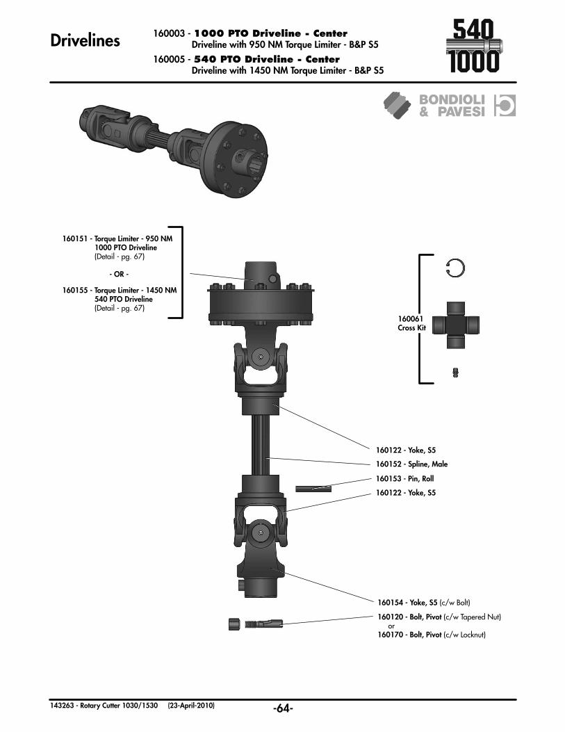
-64-143263 - Rotary Cutter 1030/1530 (23-April-2010)
Drivelines 160003 - 1000 PTO Driveline - Center Driveline with 950 NM Torque Limiter - B&P S5
160005 - 540 PTO Driveline - Center Driveline with 1450 NM Torque Limiter - B&P S5
160152 - Spline, Male
160120 - Bolt, Pivot (c/w Tapered Nut) or160170 - Bolt, Pivot (c/w Locknut)
160154 - Yoke, S5 (c/w Bolt)
160153 - Pin, Roll
160061 Cross Kit
160122 - Yoke, S5
160122 - Yoke, S5
160151 - Torque Limiter - 950 NM 1000 PTO Driveline (Detail - pg. 67)
- OR -
160155 - Torque Limiter - 1450 NM 540 PTO Driveline (Detail - pg. 67)

-65-143263 - Rotary Cutter 1030/1530 (23-April-2010)
160235 - WING 540/1000 PTO 1700 NM (15000 IN LBS) Non-Adjusting Friction Clutch - Weasler
Drivelines
160239 - Clutch Housing - (1)
119491 - Clamp - (1)
160236 - Yoke & Hub - (1)
160281 - Friction Pack - (1)
119376 - Separator Plate - (1)
119375 - Friction Disc - (2)
119377 - Pressure Plate - (1)
119391 - Spring Disc .185 - (1)
119379 - Compression Plate - (1)
118783 - Bolt, 5/16 x 2 1/2 GR8 - (6)
118427 - Nut, 5/16 - (6)
160238 - Bolt, M10 x 1.5 x 25 CL10.9 - (4)
WING - 160235 - 540/1000 PTO

-66-143263 - Rotary Cutter 1030/1530 (23-April-2010)
160273 - CENTER 540/1000 PTO 1300 NM (12000 IN LBS) Non-Adjusting Friction Clutch - Weasler
Drivelines
CENTER - 160273 - 540/1000 PTO
160239 - Clutch Housing - (1)
160241 - Yoke & Free Motion Hub - (1)
160237 - Friction Pack - (1)
119376 - Separator Plate - (1)
119375 - Friction Disc - (2)
119377 - Pressure Plate - (1)
119383 - Spring Disc - .16 (1)
119379 - Compression Plate - (1)
118783 - Bolt, 5/16 x 2 1/2 GR8 - (6)
118427 - Nut, 5/16 - (6)
160238 - Bolt, M10 x 1.5 x 25 CL10.9 - (4)
118335 - Grease Fitting - (1)

-67-143263 - Rotary Cutter 1030/1530 (23-April-2010)
160151 - Torque Limiter 950 NM - Wing 540/1000 PTO 950 NM - Center 1000 PTO160155 - Torque Limiter 1450 NM - Center 540 PTO
Drivelines
160135 - Plate, Flange Yoke (1)
160134 - Bolt & Nut (8)
160141Socket HeadScrew (4)
160136 - Bushing (1)
160132 - Lining, Torque Limiter (1)
160138 - Lining, Plate (1)
160132 - Lining, Torque Limiter (1)
160140 - Hub
160142 - Plate, Thrust
160132 - Lining, Torque Limiter
160143 - Spacer
160117 - Spring ( 950 NM)160118 - Spring (1450 NM)
160139 - Plate, Torque Limiter
160121 Bolt, Pivot (c/w Nut & Washer) (1) or160170 - Bolt, Pivot (c/w Lockut) (1)
160132 - Lining, Torque Limiter
160155 - Torque Limiter - 540 PTO - (1450 NM)
160151 - Torque Limiter - 1000 PTO - ( 950 NM)
160130 - Torque Limiter 540 & 1000 PTO (950 NM)
160130 - Torque Limiter 540 & 1000 PTO (950 NM)
Note: All parts are common with the exception of the torque limiter spring. (See Below)
-68-143263 - Rotary Cutter 1030/1530 (23-April-2010)
Gearbox Overview
Center GearboxAgainst Traffic
Center GearboxWith Traffic
Splitter Gearbox
Right Wing Gearbox
Left Wing Gearbox
1000 RPM PTO170163 - Gearbox-3080 (1:1)
540 RPM PTO170017 - Gearbox-3080 (1.71:1)
1000 RPM PTO170161 - Gearbox-3080 (1:1)
540 RPM PTO170019 - Gearbox-3080 (1.71:1)
1000 RPM PTO170011 - Gearbox-8146 (1.31:1)
540 RPM PTO170021 - Gearbox-8146 (1:1.16)
1000 RPM PTO170005 - Gearbox-3070 (1:1.25)
540 RPM PTO170015 - Gearbox-3070 (1:1.5)
1000 RPM PTO170003 - Gearbox-3070 (1:1.25)
540 RPM PTO170013 - Gearbox-3070 (1:1.5)
1000 RPM PTO170201 - Gearbox (1.3:1)
540 RPM PTO170263 - Gearbox (1:1)
1000 RPM PTO170251 - Gearbox (1:1)
540 RPM PTO170259 - Gearbox (1:1.833)
1000 RPM PTO170253 - Gearbox (1:1)
540 RPM PTO170261 - Gearbox (1:1.833)
1000 RPM PTO170255 - Gearbox (1:1.238)
540 RPM PTO170259 - Gearbox (1:1.833)
1000 RPM PTO170257 - Gearbox (1:1.238)
540 RPM PTO170261 - Gearbox (1:1.833)
Note: The direction of rotation on the outer output shafts (B) is opposite to the front input and middle output shafts (A).
A
A B B
pg.74
pg.74
pg.69
pg.69
pg.78
pg.77
pg.70
pg.70
pg.76
pg.75
pg.71
pg.71
pg.80
pg.79
pg.72
pg.72
pg.82
pg.81
pg.73
pg.73

-69-143263 - Rotary Cutter 1030/1530 (23-April-2010)
Gearboxes
170144 - (01) Fill Plug
Part # - (Qty) Description
170011 - 1000 RPM PTO Gearbox 8146 - (1.31:1)
-OR-170021 - 540 RPM PTO Gearbox 8146 - (1:1.16)
170140 - (01) Cover, 8146
170149 - (02) Shim
117165 - (01) Ball Bearing, 40mm (6208)
170139 - (01) Housing, 8146
170105 - (01) Plug
170152 - (01) Retaining Ring
170123 - (02) Seal
170141 - (02) Shaft, 8146
170111 - (02) Retaining Ring
170153 - (01) Shim
170142 - (01) Shaft, 81461000 RPM PTO
170143 - Gear Set (1.31:1)
540 RPM PTO170155 - Gear Set (1:1.16)
-OR-
170148 - (01) Retaining Ring
170148 - (01) Retaining Ring
170153 - (01) Shim
170150 - (02) Shim
117159 - (02) Roller Bearing, 35mm (30307U)
117161 - (02) Roller Bearing, 35mm (32207U)
170151 - (02) Shim
117164 - (01) Ball Bearing, 35mm (6307)
170123 - (01) Seal
170154 - (01) Seal
170146 - (02) Retaining Ring
Common Parts
170147 - (02) Retaining Ring
118530 - Lock Washer, 5/16” (2)118731 - Flat Washer, 5/16” SAE (2)
118110 - Bolt, 5/16” x 1” UNC (2)160006 - Splitter Shield (1)
1030 Model Only
Part # - (Qty) Description

-70-143263 - Rotary Cutter 1030/1530 (23-April-2010)
Gearboxes
117159 - (01) Roller Bearing, 35mm (30307U)
170116 - (06) Bolt, M6 x 16
170123 - (01) Seal
170122 - (01) Shaft, 3070
170111 - (01) Retaining Ring
1000 RPM PTO170102 - (01) Shaft & Gear (1:1.25)
540 RPM PTO170136 - (01) Shaft & Gear (1:1.5)
117162 - (01) Roller Bearing, 55mm (30211U)
117162 - (01) Roller Bearing, 55mm (30211U)
170106 - (01) Plug
170109 - (01) Shim
170115 - (01) Cap
170118 - (01) Washer
170101 - (01) Cover, 3070
170104 - (01) Fill Plug
170124 - (01) Seal, Cap
170108 - (01) Shim
117163 - (01) Ball Bearing, 35mm (6207)
170110 - (01) Retaining Ring
170121 - (01) Housing, 3070
170114 - (01) Seal
170001 - (01) Hub
170120 - (01) Cotter Pin
170105 - (01) Plug
170107 - (01) Retaining Ring
170119 - (01) Castle Nut
170003 - 1000 RPM PTO Gearbox - 3070 (1:1.25)
-OR-170013 - 540 RPM PTO Gearbox - 3070 (1:1.5)
-OR-
170117 - (06) Lock Washer
Part # - (Qty) Description

-71-143263 - Rotary Cutter 1030/1530 (23-April-2010)
Gearboxes 170005 - 1000 RPM PTO Gearbox - 3070 (1:1.25)
-OR-170015 - 540 RPM PTO Gearbox - 3070 (1:1.5)
170116 - (06) Bolt, M6 x 16
117159 - (01) Roller Bearing, 35mm (30307U)
170113 - (01) Seal, Cap
170111 - (01) Retaining Ring
1000 RPM PTO170102 - (01) Shaft & Gear (1:1.25)
540 RPM PTO170136 - (01) Shaft & Gear (1:1.5)
170100 - (01) Housing, 3070
170110 - (01) Retaining Ring
170114 - (01) Seal
170001 - (01) Hub
170120 - (01) Cotter Pin
170119 - (01) Castle Nut
170104 - (01) Fill Plug
170101 - (01) Cover, 3070
170105 - (01) Plug
170108 - (01) Shim
170103 - (01) Shaft, 3070
170112 - (01) Seal
117163 - (01) Ball Bearing, 35mm (6207)
117162 - (01) Roller Bearing, 55mm (30211U)170106 - (01) Plug
117162 - (01) Roller Bearing, 55mm (30211U)
170109 - (01) Shim
170115 - (01) Cap
170118 - (01) Washer
170107 - (01) Retaining Ring
170117 - (06) Lock Washer
-OR-
Part # - (Qty) Description

-72-143263 - Rotary Cutter 1030/1530 (23-April-2010)
Gearboxes 170161 - 1000 RPM PTO Gearbox - 3080 (1:1)
-OR-170019 - 540 RPM PTO Gearbox - 3080 (1.71:1)
117158 - (01) Roller Bearing, 35mm (30207U)
170116 - (06) Bolt, M6 x 16
170112 - (01) Seal
170128 - (01) Shaft, 3080
170107 - (01) Retaining Ring
1000 RPM PTO170164 - (01) Gear Set (1:1)
540 RPM PTO170137 - (01) Gear Set (1.71:1) 117160 - (01) Roller Bearing,
45mm (30309U)
117162 - (01) Roller Bearing, 55mm (30211U)
170106 - (01) Plug
170132 - (01) Shim
170115 - (01) Cap
170129 - (01) Washer
170126 - (01) Cover, 3080
170104 - (01) Fill Plug
170113 - (01) Seal, Cap
170108 - (01) Shim
170125 - (01) Housing, 3080
170114 - (01) Seal
170001 - (01) Hub
170131 - (01) Cotter Pin
170111 - (01) Retaining Ring
170130 - (01) Castle Nut
-OR-
170117 - (06) Lock Washer
170135 - (01) Cotter Pin
117159 - (01) Roller Bearing, 35mm (30307U)
170127 - (01) Shaft, 3080
170138 - (01) Shim
Note: No Shim on 1000 RPM PTO Gearbox
170134 - (01) Castle Nut
Part # - (Qty) Description

-73-143263 - Rotary Cutter 1030/1530 (23-April-2010)
Gearboxes
117159 - (01) Roller Bearing, 35mm (30307U)
170116 - (06) Bolt, M6 x 16
170123 - (01) Seal
170128 - (01) Shaft, 3080
170111 - (01) Retaining Ring
1000 RPM PTO170164 - (01) Gear Set (1:1)
540 RPM PTO170137 - (01) Gear Set (1.71:1)
117160 - (01) Roller Bearing, 45mm (30309U)
117162 - (01) Roller Bearing, 55mm (30211U)
170106 - (01) Plug
170132 - (01) Shim
170115 - (01) Cap
170129 - (01) Washer
170126 - (01) Cover, 3080
170104 - (01) Fill Plug
170124 - (01) Seal, Cap
170108 - (01) Shim
170125 - (01) Housing, 3080
170114 - (01) Seal
170001 - (01) Hub
170131 - (01) Cotter Pin
170107 - (01) Retaining Ring
170130 - (01) Castle Nut
170163 - 1000 RPM PTO Gearbox - 3080 (1:1)
-OR-170017 - 540 RPM PTO Gearbox - 3080 (1.71:1)
-OR-
170117 - (06) Lock Washer
170135 - (01) Cotter Pin
117158 - (01) Roller Bearing, 35mm (30207U)
170127 - (01) Shaft, 3080
170138 - (01) Shim
Note: No Shim on 1000 RPM PTO Gearbox
170134 - (01) Castle Nut
Part # - (Qty) Description

Part # - Description - (Qty)
170247 - Plug, Pressure Relief/Oil Level (01)
-74-143263 - Rotary Cutter 1030/1530 (23-Aug-2016)
170201 - 1000 RPM PTO Gearbox (1.3:1)-OR-
170263 - 540 RPM PTO Gearbox (1:1)
Gearboxes
1000 RPM PTO170230 - Gear 26T - (02)170231 - Gear 20T - (01)
540 RPM PTO170301 - Gear 18T - (03)
170236 - Gasket, Input 0.30mm - (a/r) 170237 - Gasket, Input 0.15mm - (a/r) 170238 - Gasket, Input 0.10mm - (a/r)
119365 - Cone, Bearing Timken #388 - (01)119369 - Cup, Bearing Timken #362 - (01)
119365 - Cone, Bearing Timken #388 - (04)119368 - Cup, Bearing Timken #362A - (04)
119366 - Cone, Bearing - Timken #LM603049 - (01)119367 - Cup, Bearing - Timken #LM603014- (01)
170240 - Gasket, 0.15mm (a/r)
170241 - Gasket, 0.10mm (a/r)
170213 - Seal - (02)
170234 - Seal - (02)
170233 - Shaft, Input 1.75 - 20 - (01)
170232 - Shaft, Output 1.75 - 20 - (02)
170242 - Retaining Ring - (01)
118129 - Bolt, 3/8 x 1-1/4 - (28)118503 - Lockwasher, 3/8 - (28)
170244 - Locknut - (2) 170245 - Lock Washer - (2) 170246 - Flat Washer - (2)
170239 - Gasket, 0.30mm (a/r)
-OR-

-75-143263 - Rotary Cutter 1030/1530 (23-April-2010)
Gearboxes
170261 - 540 RPM PTO Gearbox (1:1.833)
Part # - Description - (Qty)
170261
170266 - Slotted Nut, M36 x 6 - (01)
170224 - Cotter Pin, 6.3 x 60 - (01)OR
118849 - Cotter Pin, 1/4 x 2-1/2 - (01)
170271 - Output Shield - (01)
170272 - Retaining Ring - (01)
170273 - Output Seal - (01)
170274 - Spacer, Output Seal - (01)
170300 - Housing, RC-145L (01)
170299 - Output Shaft, SPL 18T - (01)
170294 - Bearing Cone, 30212 - (01)
170293 - Bearing Cup, 30212 - (01)
170298 - Output Shim - (A/R)
170292 - Key, 10 x 8 x 60 - (02)
170304 - Spacer Shaft - (01)
170297 - Spiral Gear & Pinion Set - (01)
170280 - Spacer Shaft - (01)
170295 - Lock Nut - (01)
170296 - Lock Washer - (01)
170285 - Bearing Cone, JM205149 - (01)
170284 - Bearing Cup, JM205110 - (01)
170275 - Input Seal, 19662 - (01)
170303 - Input Shim - (A/R)
170285 - Bearing Cone, JM205149 - (01)
170284 - Bearing Cup, JM205110 - (01)
170303 - Input Shim - (A/R)
170282 - Key, 12 x 8 x 38 - (02)
170290 - Input Shaft, 1.75-20 SPL - (01)
170287 - Bearing Cone, 33212 - (01)
170286 - Bearing Cup, 33212 - (01)
170270 - O-Ring, 112 - (01)
170267 - Oil Sight Glass - (01)
170268 - O-Ring, 119 - (02)
170269 - Pressure ReliefPlug - (01)
170270 - O-Ring, 112 - (02)

-76-143263 - Rotary Cutter 1030/1530 (23-April-2010)
Gearboxes
170257 - 1000 RPM PTO Gearbox (1:1.238)
Part # - Description - (Qty)
170257
170266 - Slotted Nut, M36 x 6 - (01)
170271 - Output Shield - (01)
170272 - Retaining Ring - (01)
170273 - Output Seal - (01)
170274 - Spacer, Output Seal - (01)
170289 - Housing, RC-145L (01)
170288 - Output Shaft, SPL 18T - (01)
170285 - Bearing Cone, JM205149 - (01)
170284 - Bearing Cup, JM205110 - (01)
170285 - Bearing Cone, JM205149 - (01)
170284 - Bearing Cup, JM205110 - (01)
170275 - Input Seal, 19662 - (01)
170303 - Input Shim - (A/R)
170285 - Bearing Cone, JM205149 - (01)
170284 - Bearing Cup, JM205110 - (01)
170303 - Input Shim - (A/R)
170282 - Key, 12 x 8 x 38 - (02)
170290 - Input Shaft, 1.75-20 SPL - (01)
170283 - Output Shim - (A/R)
170282 - Key, 12 x 8 x 38 - (02)
170291 - Spiral Gear & Pinion Set - (01)
170280 - Spacer Shaft - (01)
170280 - Spacer Shaft - (01)
170278 - Lock Nut - (01)
170279 - Lock Washer - (01)
170287 - Bearing Cone, 33212 - (01)
170286 - Bearing Cup, 33212 - (01)
170270 - O-Ring, 112 - (01)
170267 - Oil Sight Glass - (01)
170268 - O-Ring, 119 - (02)
170269 - Pressure ReliefPlug - (01)
170270 - O-Ring, 112 - (02)
170224 - Cotter Pin, 6.3 x 60 - (01)OR
118849 - Cotter Pin, 1/4 x 2-1/2 - (01)

170259
-77-143263 - Rotary Cutter 1030/1530 (23-April-2010)
Gearboxes
170259 - 540 RPM PTO Gearbox (1:1.833)
Part # - Description - (Qty)
170266 - Slotted Nut, M36 x 6 - (01)
170271 - Output Shield - (01)
170272 - Retaining Ring - (01)
170273 - Output Seal - (01)
170274 - Spacer, Output Seal - (01)
170287 - Bearing Cone, 33212 - (01)
170286 - Bearing Cup, 33212 - (01)
170270 - O-Ring, 112 - (01)
170300 - Housing, RC-145L (01)
170299 - Output Shaft, SPL 18T - (01)
170298 - Output Shim - (A/R) 170304 - Spacer Shaft - (01)
170297 - Spiral Gear & Pinion Set - (01)
170280 - Spacer Shaft - (01) 170295 - Lock Nut - (01)
170296 - Lock Washer - (01)
170285 - Bearing Cone, JM205149 - (01)
170284 - Bearing Cup, JM205110 - (01)
170275 - Input Seal, 19662 - (01)
170303 - Input Shim - (A/R)
170285 - Bearing Cone, JM205149 - (01)
170284 - Bearing Cup, JM205110 - (01)
170303 - Input Shim - (A/R)
170282 - Key, 12 x 8 x 38 - (02)
170277 - Input Shaft, 1.75-20 SPL - (01)
170294 - Bearing Cone, 30212 - (01)
170293 - Bearing Cup, 30212 - (01)170292 - Key, 10 x 8 x 60 - (02)
170267 - a Sight Glass - (01)
170268 - O-Ring, 119 - (02)
170269 - Pressure ReliefPlug - (01)
170270 - O-Ring, 112 - (02)
170224 - Cotter Pin, 6.3 x 60 - (01)OR
118849 - Cotter Pin, 1/4 x 2-1/2 - (01)

170255
-78-143263 - Rotary Cutter 1030/1530 (23-April-2010)
Gearboxes
170255 - 1000 RPM PTO Gearbox (1:1.238)
Part # - Description - (Qty)
170266 - Slotted Nut, M36 x 6 - (01)
170271 - Output Shield - (01)
170272 - Retaining Ring - (01)
170273 - Output Seal - (01)
170274 - Spacer, Output Seal - (01)
170289 - Housing, RC-145L (01)
170288 - Output Shaft, SPL 18T - (01)
170285 - Bearing Cone, JM205149 - (01)
170284 - Bearing Cup, JM205110 - (01)
170283 - Output Shim - (A/R)
170282 - Key, 12 x 8 x 38 - (02)
170280 - Spacer Shaft - (01)
170291 - Spiral Gear & Pinion Set - (01)
170280 - Spacer Shaft - (01) 170278 - Lock Nut - (01)
170279 - Lock Washer - (01)
170285 - Bearing Cone, JM205149 - (01)
170284 - Bearing Cup, JM205110 - (01)
170275 - Input Seal, 19662 - (01)
170303 - Input Shim - (A/R)
170285 - Bearing Cone, JM205149 - (01)
170284 - Bearing Cup, JM205110 - (01)
170303 - Input Shim - (A/R)
170282 - Key, 12 x 8 x 38 - (02)
170277 - Input Shaft, 1.75-20 SPL - (01)
170287 - Bearing Cone, 33212 - (01)
170286 - Bearing Cup, 33212 - (01)
170270 - O-Ring, 112 - (01)
170267 - Oil Sight Glass - (01)
170268 - O-Ring, 119 - (02)
170269 - Pressure ReliefPlug - (01)
170270 - O-Ring, 112 - (02)
170224 - Cotter Pin, 6.3 x 60 - (01)OR
118849 - Cotter Pin, 1/4 x 2-1/2 - (01)
-79-143263 - Rotary Cutter 1030/1530 (23-April-2010)
Gearboxes
170261 - 540 RPM PTO Gearbox (1:1.833)
Part # - Description - (Qty)
170261
170266 - Slotted Nut, M36 x 6 - (01)
170271 - Output Shield - (01)
170272 - Retaining Ring - (01)
170273 - Output Seal - (01)
170274 - Spacer, Output Seal - (01)
170300 - Housing, RC-145L (01)
170299 - Output Shaft, SPL 18T - (01)
170294 - Bearing Cone, 30212 - (01)
170293 - Bearing Cup, 30212 - (01)
170298 - Output Shim - (A/R)
170292 - Key, 10 x 8 x 60 - (02)
170304 - Spacer Shaft - (01)
170297 - Spiral Gear & Pinion Set - (01)
170280 - Spacer Shaft - (01)
170295 - Lock Nut - (01)
170296 - Lock Washer - (01)
170285 - Bearing Cone, JM205149 - (01)
170284 - Bearing Cup, JM205110 - (01)
170275 - Input Seal, 19662 - (01)
170303 - Input Shim - (A/R)
170285 - Bearing Cone, JM205149 - (01)
170284 - Bearing Cup, JM205110 - (01)
170303 - Input Shim - (A/R)
170282 - Key, 12 x 8 x 38 - (02)
170290 - Input Shaft, 1.75-20 SPL - (01)
170287 - Bearing Cone, 33212 - (01)
170286 - Bearing Cup, 33212 - (01)
170270 - O-Ring, 112 - (01)
170267 - Oil Sight Glass - (01)
170268 - O-Ring, 119 - (02)
170269 - Pressure ReliefPlug - (01)
170270 - O-Ring, 112 - (02)
170224 - Cotter Pin, 6.3 x 60 - (01)OR
118849 - Cotter Pin, 1/4 x 2-1/2 - (01)

-80-143263 - Rotary Cutter 1030/1530 (23-April-2010)
Gearboxes
170253 - 1000 RPM PTO Gearbox (1:1)
Part # - Description - (Qty)
170253
170266 - Slotted Nut, M36 x 6 - (01)
170271 - Output Shield - (01)
170272 - Retaining Ring - (01)
170273 - Output Seal - (01)
170274 - Spacer, Output Seal - (01)
170289 - Housing, RC-145L (01)
170288 - Output Shaft, SPL 18T - (01)
170285 - Bearing Cone, JM205149 - (01)
170284 - Bearing Cup, JM205110 - (01)
170285 - Bearing Cone, JM205149 - (01)
170284 - Bearing Cup, JM205110 - (01)
170275 - Input Seal, 19662 - (01)
170303 - Input Shim - (A/R)
170285 - Bearing Cone, JM205149 - (01)
170284 - Bearing Cup, JM205110 - (01)
170303 - Input Shim - (A/R)
170282 - Key, 12 x 8 x 38 - (02)
170290 - Input Shaft, 1.75-20 SPL - (01)
170283 - Output Shim - (A/R)
170282 - Key, 12 x 8 x 38 - (02)
170281 - Spiral Gear & Pinion Set - (01)
170280 - Spacer Shaft - (01)
170280 - Spacer Shaft - (01)
170278 - Lock Nut - (01)
170279 - Lock Washer - (01)
170287 - Bearing Cone, 33212 - (01)
170286 - Bearing Cup, 33212 - (01)
170270 - O-Ring, 112 - (01)
170267 - Oil Sight Glass - (01)
170268 - O-Ring, 119 - (02)
170269 - Pressure ReliefPlug - (01)
170270 - O-Ring, 112 - (02)
170224 - Cotter Pin, 6.3 x 60 - (01)OR
118849 - Cotter Pin, 1/4 x 2-1/2 - (01)

-81-143263 - Rotary Cutter 1030/1530 (23-April-2010)
Gearboxes
170259 - 540 RPM PTO Gearbox (1:1.833)
Part # - Description - (Qty)
170259
170266 - Slotted Nut, M36 x 6 - (01)
170271 - Output Shield - (01)
170272 - Retaining Ring - (01)
170273 - Output Seal - (01)
170274 - Spacer, Output Seal - (01)
170300 - Housing, RC-145L (01)
170299 - Output Shaft, SPL 18T - (01)
170298 - Output Shim - (A/R)
170292 - Key, 10 x 8 x 60 - (02)
170304 - Spacer Shaft - (01)
170297 - Spiral Gear & Pinion Set - (01)
170280 - Spacer Shaft - (01) 170295 - Lock Nut - (01)
170296 - Lock Washer - (01)
170285 - Bearing Cone, JM205149 - (01)
170284 - Bearing Cup, JM205110 - (01)
170275 - Input Seal, 19662 - (01)
170303 - Input Shim - (A/R)
170285 - Bearing Cone, JM205149 - (01)
170284 - Bearing Cup, JM205110 - (01)
170303 - Input Shim - (A/R)
170282 - Key, 12 x 8 x 38 - (02)
170277 - Input Shaft, 1.75-20 SPL - (01)
170294 - Bearing Cone, 30212 - (01)
170293 - Bearing Cup, 30212 - (01)
170287 - Bearing Cone, 33212 - (01)
170286 - Bearing Cup, 33212 - (01)
170270 - O-Ring, 112 - (01)
170267 - Oil Sight Glass - (01)
170268 - O-Ring, 119 - (02)
170269 - Pressure ReliefPlug - (01)
170270 - O-Ring, 112 - (02)
170224 - Cotter Pin, 6.3 x 60 - (01)OR
118849 - Cotter Pin, 1/4 x 2-1/2 - (01)

-82-143263 - Rotary Cutter 1030/1530 (23-April-2010)
Gearboxes
170251 - 1000 RPM PTO Gearbox (1:1)
Part # - Description - (Qty)
170251
170266 - Slotted Nut, M36 x 6 - (01)
170271 - Output Shield - (01)
170272 - Retaining Ring - (01)
170273 - Output Seal - (01)
170274 - Spacer, Output Seal - (01)
170289 - Housing, RC-145L (01)
170288 - Output Shaft, SPL 18T - (01)
170285 - Bearing Cone, JM205149 - (01)
170284 - Bearing Cup, JM205110 - (01)
170283 - Output Shim - (A/R)
170282 - Key, 12 x 8 x 38 - (02)
170280 - Spacer Shaft - (01)
170281 - Spiral Gear & Pinion Set - (01)
170280 - Spacer Shaft - (01)
170278 - Lock Nut - (01)
170279 - Lock Washer - (01)
170285 - Bearing Cone, JM205149 - (01)
170284 - Bearing Cup, JM205110 - (01)
170275 - Input Seal, 19662 - (01)
170303 - Input Shim - (A/R)
170285 - Bearing Cone, JM205149 - (01)
170284 - Bearing Cup, JM205110 - (01)
170303 - Input Shim - (A/R)
170282 - Key, 12 x 8 x 38 - (02)
170277 - Input Shaft, 1.75-20 SPL - (01)
170287 - Bearing Cone, 33212 - (01)
170286 - Bearing Cup, 33212 - (01)
170270 - O-Ring, 112 - (01)
170267 - Oil Sight Glass - (01)
170268 - O-Ring, 119 - (02)
170269 - Pressure ReliefPlug - (01)
170270 - O-Ring, 112 - (02)
170224 - Cotter Pin, 6.3 x 60 - (01)OR
118849 - Cotter Pin, 1/4 x 2-1/2 - (01)

-83-143263 - Rotary Cutter 1030/1530 (23-April-2010)
Optional Light Kit - Location
Typical Light Bracket Assembly
118011 - Bolt, 1/2” x 1-1/2” GR5 (4)
118729 - Lock Nut, 1/2” GRC - Unitorque (4)
118756 - Bolt, 1/4” x 1-1/4” GR5 (8)
118483 - Lock Nut, 1/4” GR5 - Unitorque (8)
500926 - Light Mounting Bracket (2)
RH Wiring
LH Wiring
RH Wiring
LH Wiring
Typical Light Wire Routing - 1030 Typical Light Wire Routing - 1530
Typical Light Mounting Location 1030 Right Wing 1530 Right and Left Wings
Typical Light Mounting Location 1030 Left
Note: Install lights with amber light to outside, covered lens facing forward.

-84-143263 - Rotary Cutter 1030/1530 (23-April-2010)
Optional Light Kit - Wiring
Black BrownRed Blue
WhiteWhiteRedGreen
129059 - RH Light, 4 Wire
129060 - Plug, 4 Wire (2)
129043 - 16 ga. Crimp (8)
129058 - LH Light, 4 Wire
129027 - 7 Pin Plug
3/8” Split Loom 12-15” (2)
Black
Black
RHGreen
LHGreen
White White
Red Red
Brown
Green Yellow
Red
White
Note: All spliced ends should be soldered.
BlackBrownRedBlue
WhiteWhiteRed Green
129065 - Wire,4 x 16 ga. - 24’
129066 - Wire,4 x 16 ga. - 25’
15’ Model
129067 - Wire,4 x 16 ga. - 21’
10’ Model
501533 - Light Kit Includes:
• Lights (Left & Right)
• 7 Pole Plug Connector
• 16 Gauge Wiring
• Mounting Brackets
• All Required Hardware

Left Wing Layout Right Wing Layout
-85-143263 - Rotary Cutter 1030/1530 (23-April-2010)
Optional Winch Kit
129063 - Winch, 1500 LB (1)
118511 - Flat Washer, 3/8 (3)
118005 - Bolt, 3/8” x 1” GR5 (3)
500916 - Cable/Hook Assembly (1)
118417 - Lock Nut, 3/8” GR5 (3)
500917 - Pulley Block (1)
501534 - Winch Kit (Hardware Included)
500925 - Winch Mount Assembly (1)
118073 - Bolt, 1” x 3-1/2” UNC GR8 (2)
118456 - Lock Nut, 1” UNC GR5 (4)
500920 - Hook Plate Assembly (2)
118103 - Bolt, 1” x 2-1/2” UNC GR5 (2)
Winch Location Rear View of Cutter
Optional Tow Hitch501535 - Tow Hitch Kit (Hardware Included)
118011 - Bolt, 1/2” x 1-1/2” GR5 (10)
118729 - Lock Nut, 1/2” GRC - Unitorque (10)
Note: Refer to operation and safety instructions found in the operators section of the manual - (pg. 34)

-86-143263 - Rotary Cutter 1030/1530 (23-April-2010)
Optional Wing Guide Wheels
Optional Toolbox
118483 - Lock Nut, 1/4” GRC - Unitorque (2)
500852 - SMV Sign Extension (1)
118983 - Bolt, 1/4” x 3/4” UNC GR5 (2)
118512 - Flat Washer, 1/2” (4)
118009 - Bolt, 1/2” x 1-1/4” UNC GR5 (4)
133103 - Toolbox, 8-3/4” x 32” x 9 1/2” (1)
500851 - Toolbox Mount Bracket -LH (1)
118729 - Lock Nut, 1/2” GRC - Unitorque (4)
118447 - Lock Nut, 5/8” GRC - Unitorque (4)
500850 - Toolbox Mount Bracket -RH (1)
118514 - Flat Washer, 5/8 (4)
118026 - Bolt, 5/8” x 2” GR5 (4)
501536 - Toolbox/Blade Storage Kit (Hardware Included)
501580 - Wing Guide Wheel - RH (shown)501581 - Wing Guide Wheel - LH
118417 - Lock Nut, 3/8” UNC (3)118511 - Flat Washer, 3/8 (3)
118146 - Bolt, 3/8” x 3-1/2” UNC (3)
118729 - Lock Nut, 1/2”UNC GRC - Unitorque (3)118512 - Flat Washer, 1/2 F436 (3)
118219 - Carriage Bolt, 1/2” x 2” UNC (3)
118962 - Lock Nut, 1-1/4” UNF Gr 8 (1)
131206 - Washer, Flat 1-1/4 SAE (2)
500330 - Bolt,1-1/4 X 7-1/2 UNF c/w Grease Fitting (1)
501582 - Guide Wheel Bracket - RH(501583 - Guide Wheel Bracket - LH)
501625 - Steel Wheel Assembly (1)
501629 - Spacer Bushing, 1-3/4” OD (2)
131531 - Retaining Ring, 2-7/16” (2)131530 - Dust Seal - 1.75” ID (2)
131529 - Tapered Bearing, Cone (2)131528 - Tapered Bearing, Race (2)
(comes with bearings)

-87-143263 - Rotary Cutter 1030/1530 (23-April-2010)
2 YearLimited Warranty
Degelman Industries Ltd. (“Degelman”) warrants to the original purchaser of a new 1030/1530 Degelman Rotary Cutter, purchased from an authorized Degelman dealer, that the equipment will be free from defects in material and workmanship for a period of two (2) years from the date of delivery, for non-commercial use (including farm, institutional, government, and municipality) and (1) year from the date of delivery for commercial use. The obligation of Degelman to the purchaser under this warranty is limited to the repair or replacement of defective parts in the first year and to the provision, but not the installation of replacement parts in the second year. Degelman reserves the right to inspect any equipment or parts which are claimed to have been defective in material or workmanship.
Replacement or repair parts installed in the equipment covered by this limited warranty are warranted for ninety (90) days from the date of delivery of such part or the expiration of the applicable new equipment warranty period, which ever occurs later. Warranted parts shall be provided at no cost to the user at an authorized Degelman dealer during regular working hours. Warranted replacement parts will either be replaced or rebuilt at Degelman’s discretion.
Disclaimer of implied warranties & consequential damages
This warranty shall not be interpreted to render Degelman Industries Ltd. liable for injury, death, property damage or damages of any kind, whether direct, consequential, or contingent to property. Without limiting the generality of the foregoing, Degelman shall not be liable for damages resulting from any cause beyond its reasonable control, including, without limitation, loss of crops, any expense or loss of labour, supplies, rental machinery or loss of use.
No other warranty of any kind whatsoever, express or implied is made with respect to this sale; and all implied warranties of merchantability and fitness for a particular purpose which exceed the obligations set forth in this written warranty are hereby disclaimed and excluded from this sale. This exclusion shall not apply in any jurisdiction where it is not permitted by law.
This limited warranty shall not apply:
1. If, in the sole opinion of Degelman, the unit has been subjected to misapplication, abuse, misuse, negligence or accident.2. To any goods that have sustained damage or deterioration attributable to contact with foreign objects (eg. stones,
iron, and other material other than grass and brush.)3. If parts not made or supplied by Degelman have been used in the connection with the unit, if, in the sole judgement
of Degelman such use affects its performance, safety, stability or reliability.4. If the unit has been altered or repaired outside of an authorized Degelman dealership in a manner which, in the
sole judgement of Degelman, affects its performance, safety, stability or reliability.5. To normal maintenance service and normal replacement items such as gearbox lubricant, hydraulic fluids, and
seals.6. To expendable or wear items such as blades, blade bolts, skid pans, skid shoes and any other items that in the
company’s sole judgement is a wear item.
No employee or representative of Degelman Industries Ltd. is authorized to change this limited warranty in any way or grant any other warranty unless such change is made in writing and signed by the Degelman Service Manager.
This limited warranty is subject to any future availability of supply, which may directly affect Degelman’s ability to obtain materials or manufacture replacement parts.
Degelman reserves the right to make improvements in design or changes in specifications at any time, without incurring obligations to owners of equipment previously delivered.
This limited warranty is subject to compliance by the customer to the enclosed Retail Customer’s Responsibility Under Degelman Warranty.
Make certain the warranty registration card has been forwarded to: Degelman Industries Ltd. Box 830 272 Industrial Dr. Regina, Sk., Canada S4P 3B1
Warranty