operator product catalog manual second edition · product catalog second edition operator manual...
TRANSCRIPT

Product Catalog
Second Edition
OPERATORMANUALBIPRO SDS CB200
BICARBONATE MIXER FOR
HEMODIALYSISC600 CONTROLLER

IT IS UNSAFE TO START USING THIS DEVISEWITHOUT FIRST READING AND UNDERSTANDING
THIS MANUAL IN ITS ENTIRETY
OPERATOR MANUALFOR
BIPRO SDS CB200BICARBONATE MIXER
FOR HEMODIALYSIS
C600 CONTROLLER
IMPORTANT DOCUMENTPLEASE SAFEGUARD
September 15, 2015

TABLE OF CONTENTS
USER ASSISTANCE INFORMATION 3
GENERAL DESCRIPTION 3 WARNINGS, CAUTIONS &RECOMMENDATIONS 4
BICARBONATE CONCENTRATE OPERATING PROCEDURE INSERT AThis section consists of thirteen (13) pages OPI-001 1/13 to OPI -001 13/13
TROUBLE SHOOTING GUIDE INSERT BThis section consists of four (4) pages TRB-001 1/4 to TRB-001 4/4
PARTS LIST 5
COMPONENT DIAGRAM 6
COMPONENT LIST 7
MARCH PUMP DETAIL 8
WAKI PUMP DETAIL 9
BICARBONATE SYSTEM LOG (SAMPLE) 10
Page 2

USER ASSISTANCE INFORMATION
ASSISTANCE IS AVAILABLE: Monday through Friday (excluding holidays) 8:00 am to 4:00 pm Central time.
Call: 913-438-9700
Emergency assistance is available after normal operating hours,
Call: 913-269-5681 JACK DILLON'S CELL
If the phone fails to answer please leave a message, include the contact name and a phone number that will be answered before business hours.
GENERAL DESCRIPTION
The BiPro SDS CB200 Bicarbonate mixing and distribution system is a dual tank pump driven bicarbonate mixer. When operating instructions are followed mixing bicarbonate in quantities up to 100 gallons is easy and accurate. It is possible to disinfect the system with multiple disinfection solutions.
The specific instructions for all procedure’s are included in this manual.
Page 3

WARNINGS, CAUTIONS & RECOMMENDATIONS
WARNING: It is unsafe to operate the Bicarbonate system without first reading and understanding the Operator’s Instruction Manual
WARNING: Misuse, improper operation, and/or improper monitoring of the system could result in serious injury, death, or serious reactions to patients undergoing hemodialysis treatment.
CAUTION: When used as a medical devise, Federal law restricts this devise to sale by or on the order of a physician.
NOTE: Where water is mentioned, it must be AMA standard quality water
NOTE: Once the BiPro SDS CB200 system has been delivered to you, it is the responsibility of the Medical Director to ensure that the system is used, monitored, and maintained in such a manner so as to satisfy all applicable standards.
RECOMMENDATIONS: Disinfection of this system prior to use and on a recurring schedule is required. Disinfection chemicals and quantities are to be determined by the medical director. Common disinfectants approved for use with this equipment are, chlorine bleach in a 100:1, ratio, Renlin in a 100:1ratio, and Ozone @ 0.2ppm. (MSI’s target for the Mixing tank is 0.20 ppm or greater, (as read directly from the Hach colorimeter). Higher levels up to 3.0 ppm will not hurt, levels over that are not unacceptable. MSI’s target for the end of the loop is 0.10 or greater). Precipitate removal can be accomplished with vinegar or acetic acid used in a 20:1 ratio. Disinfection scheduling is to be determined by the Medical Director of the facility. Precipitate removal should be accomplished on a minimum of a monthly basis.
Filter changes for the 0.2 micron air filters are to be accomplished on a annual basis. Carbon ozone elimination filters (if used) should be changed on an annual basis. Stainless Steel Screens should be removed and rinsed on a annual basis.
Solenoids should be dissembled and rinsed on an annual basis. Page 4

Control Panel
100
95
90
85
80
75
70
65
60
55
50
45
40
35
30
25
20
15
350
300
250
200
150
100
100
95
90
85
80
75
70
65
60
55
50
45
40
35
30
25
20
15
350
300
250
200
150
100
Mix Tank Day Tank
Mix Tank Drain
SDSCB200-OPI-001Bi-Carb Mixing Tanks
Day Tank Drain
Day Tank Lid
Mix Tank Lid

BICARB MIXING AND DISTRIBUTION
OPERATING INSTRUCTIONS
SDS-CB200
! ! ! ! ! !MEDICAL SOLUTIONS INTERNATIONAL
800-326-5275
REVISION 9 9/15/15 L SDSCB200-OPI-001 1/13

BICARB MIXING PROCEDURE
Purpose: To enable assigned staff to properly prepare BICARB
Supplies: BICARB powder
Procedure: Performed by trained staff
1. Insure all panel mounted switches are Turned Off. Verify the BICARB Mixer is completely empty: Open Mix tank drain if necessary ....... Close Mix tank drain when empty. Open Day tank drain if necessary ....... Close Day tank drain when empty.
2. The Panel-view C600 touch pad consist of three modes; F 1, = Fill Menu, F 2, = Mix Menu, & F 3, = AUTO. To enter the Fill mode from the main menu: PRESS, F1, The Screen will change and Display: "Enter Fill Count" PRESS, the Blue Square, A numerical touch pad will appear, ENTER, NUMBER OF LITERS DESIRED FOR THIS BATCH,
PRESS, THE ENTER ARROW (lower right) on the numerical touchpad. PRESS, F8, Continue. FYI:(FOR 1 BAG OF BICARB POWDER, ENTER 94 LITERS) (FOR 2 BAGS OF BICARB POWDER, ENTER 188 LITERS) (FOR 3 BAGS OF BICARB POWDER, ENTER 282 LITERS) (FOR 4 BAGS OF BICARB POWDER, ENTER 376 LITERS)
The fill count will show on the screen and will count up to the requested amount. When fill is complete, the flow will stop,Verify the water level in the Mix Tank.
3. PRESS, F5 TO RETURN TO THE MAIN MENU.
4. To enter the Mix mode from the main menu: PRESS, F2,
PRESS, F8, Continue. The pump will start. A default setting of 10 minutes is in the system. **While it should not be necessary, if you need to alter the mix pump time run time: PRESS F5, (this returns you to the main menu) PRESS F2, (this enters you into the mix mode) Press, the Blue Square, A numerical touch pad will appear, ENTER NUMBER OF MINUTES DESIRED FOR THIS BATCH, PRESS THE ENTER ARROW (lower right) on the numerical touchpad.THEN PRESS F8.
5. Open the lid on the Bicarb Mixing Tank: Slowly add the appropriate number of BICARB packages. Close the lid. Allow solution to mix for full cycle, It will automatically shut off.
6. When Mix Cycle is complete: PRESS, F5 TO RETURN TO THE MAIN MENU. 7. Capture a sample from the “Mix Tank” sample port for testing by...... opening the Ball Valve and clear a few ounces into a container, throw away Then Capture a sample from the “Mix Tank” sample port. Test your mixed BICARB to insure it meets your facility standards. If you test
For Specific Gravity your sample should be ____ with a tolerance of + or - ___. OR
For Conductivity your sample should be ____ with a tolerance of + or - ___.
REVISION 9 9/15/15! L ! ! ! ! ! ! ! SDSCB200-OPI-001 2/13

8. ! When Batch is verified: ! Turn on the Safety Switch (#4) Turn on the Prime Loop Switch (#5) to prime the loop.
Enter Mix: PRESS, F2, (You are now purging the loop of rinse water and air.) PRESS, F8, Continue. Continue to purge the loop for (5) minutes) 9. After 3 to 5 minutes, Verify that pure mixed BICARB has filled the loop by drawing a sample from the loop sample port on the right of the control panel podium,test as you did in step #7. Once Verified: Press F5, Main Menu, CLOSE THE DAY TANK DRAIN,
Enter Mix mode: PRESS, F2, PRESS, F8, Continue.
Turn On the Transfer to Day Tank Switch (#8) to begin transfer to day tank.
Turn On the Fill/Mix Switch, (#1) (THIS CLOSES THIS VALVE)
Turn Off the Prime Loop Switch (#5) to stop priming the loop.
Allow to transfer for 30 seconds,(to accumulate bicarb in the Day Tank) then proceed: 11. After 30 seconds, Turn On the Loop Pump Loop Switch (#6)
The unit will automatically shut off and sound the dry cut alarm when transfer is complete. 12. When the dry cut alarm sounds, transfer is compete, PRESS, F1, TO MUTE, PRESS, F5, TO RETURN TO THE MAIN MENU.
Turn Off the Fill/Mix Switch (#1),
Turn Off the Transfer to Day Tank Switch (#8).
Turn Off the Safety Switch (#4).
13. OPEN MIX TANK DRAIN. On the Panel-view C600 touch pad, PRESS, F1, PRESS, F8, Continue,
Turn On the Spray Mix Tank Switch (#2). Allow to spray for 15 liters,
PRESS, F5,
Turn Off the Spray Mix Tank Switch (#2).
14. On the Panel-view C600 touch pad, to monitor the low tank alarm, PRESS, F3
The Distribution System is now in normal operation.
! ! If a dry cut alarm occurs during the Mix or Auto mode the unit will stop and display DRY CUT ALARM. ! ! PRESS F1, then F5 to clear the alarm and exit to the main menu. (See Trouble Shooting Guide).! ! If a low tank alarm occurs the tank alarm screen shows which sensor(s) are reading an alarm state. ! ! LOW TANK, refers to the Bicarb Day Tank, TO SILENCE the audio alarm, PRESS, F 1, ! ! This will shut off the alarm until the alarm condition clears or a new alarm occurs. ! ! To resolve the alarm status either more bicarb needs to be mixed, tested and transferred, if remaining ! ! quantity is sufficient to complete the operational day simply press, F5. ! ! If a new alarm occurs it will display but not alarm unless the first alarm has cleared.
! ! Blank lines that appear in these instructions are to be completed by the facility.
THESE PROCEDURES ARE INTENDED TO BE GUIDELINES FOR USE IN ESTABLISHING YOUR FACILITIES PROCEDURES
REVISION 9 9/15/15! L ! ! ! ! ! ! SDSCB200-OPI-001 3/13

MID DAY BICARB MIXING PROCEDURE
Purpose: To enable assigned staff to properly prepare BICARB
Supplies: BICARB powder
Procedure: Performed by trained staff
1. With the exception of the Loop Pump switch (#6). (the loop should be recirculating) Insure all panel mounted switches are Turned Off. Verify the BICARB Mixer is completely empty: Close the mix tank drain when empty.
2. To enter the Fill mode from the main menu: PRESS, F1, The Screen will change and Display: "Enter Fill Count" PRESS, the Blue Square, A numerical touch pad will appear, ENTER, NUMBER OF LITERS DESIRED FOR THIS BATCH,
PRESS, THE ENTER ARROW (lower right) on the numerical touchpad. PRESS, F8, Continue.The fill count will show and count up to the requested amount. When fill is complete the flow will stop, Verify the water level in theBicarb Mix Tank. PRESS F5 TO RETURN TO THE MAIN MENU.
3. To enter the Mix mode from the main menu: PRESS, F2,
PRESS, F8, Continue. The pump will start. A default setting of 10 minutes is in the system.
4. Open the lid on the Bicarb Mixing Tank: Slowly add the appropriate number of BICARB packages. Close the lid.
5. When Mix Cycle is complete: PRESS, F5, To return to the main menu.
6. Capture a sample from the “Mix Tank” sample port
Test your mixed BICARB to insure it meets your facility standards.
7.* If you are ready to transfer to the day tank proceed,
if you want to wait until needed then resume at this point on your return.
Turn On the Safety Switch (#4) Turn On the Transfer to Day Tank Switch (#8), Turn On the Fill/Mix (#1), (THIS WILL CLOSE THIS VALVE ) Enter the Mix mode from the main menu: PRESS, F2,
PRESS, F8, Continue.
8. The bicarb will transfer until the mix tank is empty, then the dry cut alarm sounds, Press F1 To Mute ..... Press F5 To return to the main menu.
Turn Off the Fill/Mix Switch (#1),
Turn Off the Transfer to Day Tank Switch (#8)
Turn Off the Safety Switch (#4)
9. On the Panel-view C600 touch pad, to monitor the low tank alarm, PRESS F3
The Distribution System is now in normal operation.
REVISION 9 9/15/15 ! ! ! ! ! ! ! SDSCB200-OPI-001 4/13

RECOMMENDED BICARB PRECIPITATE REMOVAL PROCEDURE
Purpose: To enable assigned staff to properly rinse the system with acidic rinse.
Supplies: Prescribed disinfectant.
Rubber Gloves and Goggles recommended
BEFORE BEGINNING PROCEDURE, PERSONALLY VISUALLY VERIFY THAT
NO PATIENTS ARE RECEIVING TREATMENT.
1. Insure all panel mounted switches are Turned Off. Verify the tanks are completely empty: Open mix tank drain if necessary. Close Mix Tank Drain, Close Day Tank Drain.
2. Enter the Fill mode from the main menu: PRESS, F1, The Screen will change and Display: "Enter Fill Count" PRESS, the Blue Square, A numerical touch pad will appear, ENTER, 100 LITERS, PRESS THE ENTER ARROW (lower right) on the touchpad. PRESS, F8, Continue. The fill count will show on the screen and count up to requested amount. When fill is complete the flow will stop, Verify the water level in the Bicarb Mix Tank.
PRESS, F5 TO RETURN TO THE MAIN MENU.
3. To enter the Mix mode from the main menu: PRESS, F2,
PRESS, F8, Continue. The pump will start. A default setting of 10 minutes is in the system. 4. Open the lid on the Bicarb Mixing Tank: Add the appropriate amount of the acidic rinse of choice. Close the lid. Capture a sample from the Mix Tank sample port for testing.
5. Once verified: TURN ON THE SAFETY SWITCH (#4) Turn On the Spray Mix Tank Switch (#2)........... After 30 seconds Turn Off this switch. Turn On the Mix Pump Backwash Switch(#3)..... After 10 seconds Turn Off this switch. Turn On the Injector Switch (#7).................... After 30 seconds Turn Off this switch. Turn On the Transfer to Day Tank Switch(#8)..... After 30 seconds Turn Off this switch. Turn On the Spray Day Tank Switch (#9)............ After 30 seconds Turn Off this switch. Turn On the Prime Loop Switch (#5).................... This switch is to be left on. Turn On the Loop Pump Backwash Switch(#10)... After 10 seconds Turn Off this switch.
6. After 5 minutes, verify that Low pH Solution has filled the loop, draw a sample from the loop sample port on the right of the podium and test as you did in step #4. When verified: Turn Off the Prime Switch (#5),
Turn Off the Safety Switch. (#4)
PRESS, F5, To return to the main menu.
7. Turn On the Loop Pump switch (#6), With the solution re-circulating, now would be the time to flush each wall station Bicarb port. 8. After flushing wall station Bicarb ports:
Turn Off all panel mounted switches. Open Mix Tank Drain. Open Day Tank Drain. Allow for contact time (minimum 15 min).
9. Proceed to the Disinfectant Rinse Procedure, or Chemical Disinfect procedure,
or Pre-Ozonation rinse procedure.
NEVER LEAVE LOW PH RINSE IN THE SYSTEM.
REVISION 9 9/15/15! L ! ! ! ! ! ! SDSCB200-OPI-001 5/13
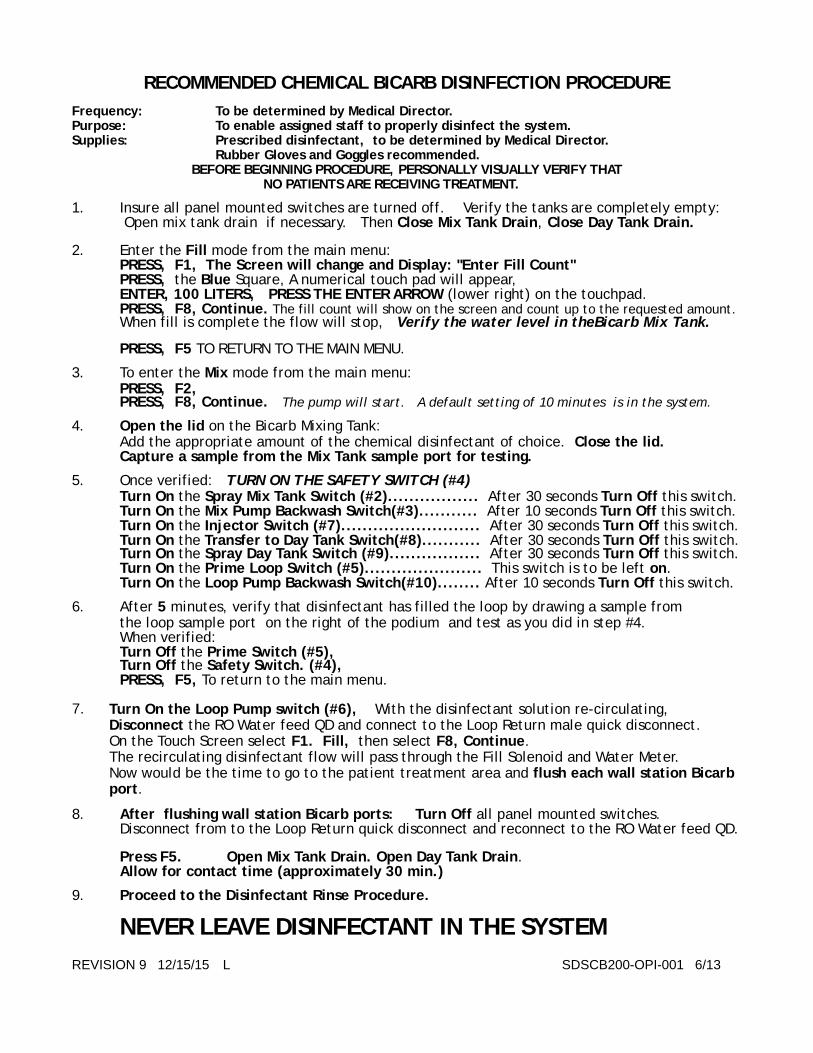
RECOMMENDED CHEMICAL BICARB DISINFECTION PROCEDURE
Frequency: To be determined by Medical Director.
Purpose: To enable assigned staff to properly disinfect the system.
Supplies: Prescribed disinfectant, to be determined by Medical Director.
Rubber Gloves and Goggles recommended. BEFORE BEGINNING PROCEDURE, PERSONALLY VISUALLY VERIFY THAT
NO PATIENTS ARE RECEIVING TREATMENT.
1. Insure all panel mounted switches are turned off. Verify the tanks are completely empty: Open mix tank drain if necessary. Then Close Mix Tank Drain, Close Day Tank Drain.
2. Enter the Fill mode from the main menu: PRESS, F1, The Screen will change and Display: "Enter Fill Count" PRESS, the Blue Square, A numerical touch pad will appear, ENTER, 100 LITERS, PRESS THE ENTER ARROW (lower right) on the touchpad. PRESS, F8, Continue. The fill count will show on the screen and count up to the requested amount. When fill is complete the flow will stop, Verify the water level in theBicarb Mix Tank.
PRESS, F5 TO RETURN TO THE MAIN MENU.
3. To enter the Mix mode from the main menu: PRESS, F2, PRESS, F8, Continue. The pump will start. A default setting of 10 minutes is in the system. 4. Open the lid on the Bicarb Mixing Tank: Add the appropriate amount of the chemical disinfectant of choice. Close the lid. Capture a sample from the Mix Tank sample port for testing.
5. Once verified: TURN ON THE SAFETY SWITCH (#4) Turn On the Spray Mix Tank Switch (#2)................. After 30 seconds Turn Off this switch. Turn On the Mix Pump Backwash Switch(#3)........... After 10 seconds Turn Off this switch. Turn On the Injector Switch (#7).......................... After 30 seconds Turn Off this switch. Turn On the Transfer to Day Tank Switch(#8)........... After 30 seconds Turn Off this switch. Turn On the Spray Day Tank Switch (#9)................. After 30 seconds Turn Off this switch. Turn On the Prime Loop Switch (#5)...................... This switch is to be left on. Turn On the Loop Pump Backwash Switch(#10)........ After 10 seconds Turn Off this switch.
6. After 5 minutes, verify that disinfectant has filled the loop by drawing a sample from the loop sample port on the right of the podium and test as you did in step #4. When verified: Turn Off the Prime Switch (#5), Turn Off the Safety Switch. (#4),
PRESS, F5, To return to the main menu.
7. Turn On the Loop Pump switch (#6), With the disinfectant solution re-circulating, Disconnect the RO Water feed QD and connect to the Loop Return male quick disconnect. On the Touch Screen select F1. Fill, then select F8, Continue. The recirculating disinfectant flow will pass through the Fill Solenoid and Water Meter. Now would be the time to go to the patient treatment area and flush each wall station Bicarb
port.
8. After flushing wall station Bicarb ports: Turn Off all panel mounted switches. Disconnect from to the Loop Return quick disconnect and reconnect to the RO Water feed QD. Press F5. Open Mix Tank Drain. Open Day Tank Drain. Allow for contact time (approximately 30 min.)
9. Proceed to the Disinfectant Rinse Procedure.
NEVER LEAVE DISINFECTANT IN THE SYSTEM
REVISION 9 12/15/15 L SDSCB200-OPI-001 6/13

DISINFECTANT RINSE PROCEDURE
Purpose: To enable assigned staff to properly rinse the system.
Supplies: RO Water
Procedure to be performed every time the SYSTEM HAS BEEN DISINFECTED.
1. Insure all panel mounted switches are turned off. Open Mix Tank Drain, Open Day Tank Drain. 2. Enter the Fill mode from the main menu: PRESS, F1, The Screen will change and Display: "Enter Fill Count" PRESS, the Blue Square, A numerical touch pad will appear, ENTER, 700 LITERS, PRESS THE ENTER ARROW (lower right) on the touchpad. PRESS, F8, Continue. Allow to run to drain for approximately 30 LITERS.
3. Turn On the Mix Pump Backwash Switch(#3)
Turn On the Fill/Mix Switch (#1) Allow to run for approximately 30 more LITERS.
Turn On the Injector Switch(#7), Turn Off the Mix Pump Backwash Switch(#3)
Allow to flow to drain for approximately 30 more LITERS Turn On the Spray Mix Tank Switch (#2), Turn Off the Injector Switch,(#7)
Allow 80 more LITERS to spray into the mixing tank and run to drain, 4. Turn On the Safety Switch (#4). Turn On the Transfer to Day Tank Switch (#8).
Turn Off the Spray Mix Tank Switch (#2). Allow 30 LITERS to flush the transfer plumbing, Turn On the Spray Day Tank Switch (#9).
Turn Off the Transfer to Day Tank Switch (#8). Allow 80 LITERS to spray the Day tank.
5. Turn On the Prime Switch (#5), (This will remain on.) Turn Off the Spray Day Tank Switch (#9)
Turn On the Loop Pump Backwash (#10) Allow 40 LITERS to back flush the loop pump. Turn Off the Loop Pump Backwash Switch (#10)
With Prime switch still on, Purge the loop for approximately 80 more LITERS Verify disinfectant has been rinsed from the loop, draw the samples from the loop sample port.
6. When no disinfectant is detected at the loop return sample port, Proceed to the patient treatment floor and open each Bicarb Valve and allow rinse water to to flow to drain. Test for absence of disinfectant. Return to Bicarb System, retest the end of the loop, When clear, proceed
7. Turn On and Off the Prime Switch (#5) Six times (On and Off) to clear the re-circulation valve. Leave Off. Turn On the Spray Day Tank Switch (#9), Allow 40 more LITERS to spray the Day tank. 8. Close the Mix Tank Drain, Close the Day Tank Drain. Turn Off the Fill/Mix switch (#1),
Turn Off the Spray Day Tank Switch (#9)
Turn Off the Prime Switch (#5),
Turn On the Transfer switch (#8).
9. Open the Day tank sample port, With the level of the Day tank higher than the sample port. allow water to flow through. Begin testing for absence of disinfectant. When clear proceed. 10. Open the Mix tank sample port, With the level of the Mix tank higher than the sample port. and allow water to flow through. Begin testing for absence of disinfectant. When clear, proceed 11. If you do not want to Recirculate water through the loop over night: Turn Off Any and All Remaining Switches. Open the Mix Tank Drain.
Open the Day Tank Drain, Press F5 on Panel-view C600 to clear.
If you want to Recirculate water through the loop overnight: Turn off Any and All Remaining Switches. Open the Mix Tank Drain only.
Turn on the Loop Pump Switch(#6), Press F5 on Panel-view C600 to clear.
REVISION 9 9/15/15 L SDSCB200-OPI-001 7/13

PRE OZONATION RINSE PROCEDURE
Purpose: To enable assigned staff to properly rinse the system prior to Ozonation.
Supplies: RO Water
BEFORE BEGINNING PROCEDURE, VISUALLY VERIFY
THAT NO PATIENTS ARE RECEIVING TREATMENT.
1. Insure all panel mounted switches are deactivated. Open Mix Tank and Day Tank drain. Drain sample ports 2. Enter the Fill mode from the main menu: PRESS, F1, The Screen will change and Display: To "Enter Fill Count" PRESS, the Blue Square, A numerical touch pad will appear, ENTER, 500 LITERS,
PRESS, THE ENTER ARROW (lower right) on the touchpad. PRESS, F8 Continue. Allow 20 Liters to run to drain. (WATCH COUNT ON SCREEN 3. Turn On the Injector Switch (#7)
Turn On the Mix Pump Backwash Switch (#3)
Allow 30 Liters to flow to drain (WATCH COUNT ON SCREEN)
4. Turn Off the Injector Switch (#7)
Turn Off the Mix Pump Backwash Switch (#3)
Turn On the Spray Mix Tank Switch (#2)
Turn On the Fill/Mix Switch (#1)
Allow 30 Liters to spray into the Mix Tank and run to drain. (WATCH COUNT ON SCREEN)
5. Turn On the Safety Switch (#4)
Turn On the Spray Day tank Switch (#9)
Turn Off the Spray Mix Tank Switch (#2)
Allow 30 Liters to spray into the Day Tank and run to drain. ( WATCH COUNT ON SCREEN )
6. Turn On the Transfer to Day Tank Switch (#8)
Turn Off the Spray Day tank Switch (#9)
Allow 20 Liters to run into the Day Tank and run to drain. ( WATCH COUNT ON SCREEN )
7. Turn On the Prime Loop Switch (#5)
Turn Off the Transfer to Day Tank Switch (#8),
Turn On the Loop pump Backwash switch (10),
Allow 10 liters to run to drain. Turn Off the Loop pump Backwash switch (10).
8. After 40 Liters have flushed through the loop and run to drain,
start with the first wall station and flush each wall station Bicarb port. Return to the Bicarb control, start manipulating the Prime Loop Switch (#5), on/off a minimum of 6 times. This will clear the recirculation solenoid and tubing. Turn On the Spray Day Tank (#9)
Allow 10 Liters to spray into the Day Tank and to drain.
9. When complete, the loop will be flushed, Close the day tank drain, Turn On the Transfer to Day Tank Switch (#8)
Turn Off the Prime Loop Switch (#5)
Allow at least 40 Liters to enter the Day Tank, Flush the Day Tank Sample Port. Turn On the Loop Pump Switch (#6).
10. Close the Mix tank drain. Turn Off the Fill/Mix Switch,
Turn Off the Transfer Switch. Allow at least 40 Liters to enter the Mix Tank, Flush the Mix Tank Sample Port.
Press F5, deactivate all panel mounted switches, Open both drains
Proceed to Ozonation Procedure.
!REVISION 9 9/15/15! L SDSCB200-OPI-001 8/13
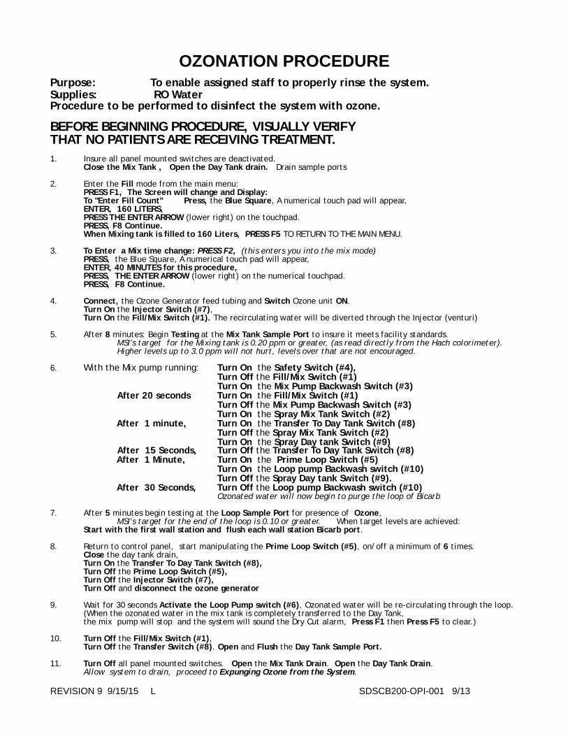
OZONATION PROCEDUREPurpose: To enable assigned staff to properly rinse the system.
Supplies: RO Water
Procedure to be performed to disinfect the system with ozone.
BEFORE BEGINNING PROCEDURE, VISUALLY VERIFY
THAT NO PATIENTS ARE RECEIVING TREATMENT.
1. Insure all panel mounted switches are deactivated. Close the Mix Tank , Open the Day Tank drain. Drain sample ports 2. Enter the Fill mode from the main menu: PRESS F1, The Screen will change and Display:
To "Enter Fill Count" Press, the Blue Square, A numerical touch pad will appear, ENTER, 160 LITERS,
PRESS THE ENTER ARROW (lower right) on the touchpad. PRESS, F8 Continue. When Mixing tank is filled to 160 Liters, PRESS F5 TO RETURN TO THE MAIN MENU.
3. To Enter a Mix time change: PRESS F2, (this enters you into the mix mode) PRESS, the Blue Square, A numerical touch pad will appear, ENTER, 40 MINUTES for this procedure,
PRESS, THE ENTER ARROW (lower right) on the numerical touchpad. PRESS, F8 Continue.
4. Connect, the Ozone Generator feed tubing and Switch Ozone unit ON. Turn On the Injector Switch (#7), Turn On the Fill/Mix Switch (#1). The recirculating water will be diverted through the Injector (venturi) 5. After 8 minutes: Begin Testing at the Mix Tank Sample Port to insure it meets facility standards. MSI’s target for the Mixing tank is 0.20 ppm or greater, (as read directly from the Hach colorimeter). Higher levels up to 3.0 ppm will not hurt, levels over that are not encouraged. 6. With the Mix pump running: Turn On the Safety Switch (#4), Turn Off the Fill/Mix Switch (#1)
Turn On the Mix Pump Backwash Switch (#3)
After 20 seconds Turn On the Fill/Mix Switch (#1)
Turn Off the Mix Pump Backwash Switch (#3)
Turn On the Spray Mix Tank Switch (#2)
After 1 minute, Turn On the Transfer To Day Tank Switch (#8)
Turn Off the Spray Mix Tank Switch (#2)
Turn On the Spray Day tank Switch (#9) After 15 Seconds, Turn Off the Transfer To Day Tank Switch (#8)
After 1 Minute, Turn On the Prime Loop Switch (#5)
Turn On the Loop pump Backwash switch (#10)
Turn Off the Spray Day tank Switch (#9).
After 30 Seconds, Turn Off the Loop pump Backwash switch (#10) Ozonated water will now begin to purge the loop of Bicarb
7. After 5 minutes begin testing at the Loop Sample Port for presence of Ozone, MSI’s target for the end of the loop is 0.10 or greater. When target levels are achieved: Start with the first wall station and flush each wall station Bicarb port. 8. Return to control panel, start manipulating the Prime Loop Switch (#5), on/off a minimum of 6 times. Close the day tank drain, Turn On the Transfer To Day Tank Switch (#8),
Turn Off the Prime Loop Switch (#5),
Turn Off the Injector Switch (#7),
Turn Off and disconnect the ozone generator
9. Wait for 30 seconds Activate the Loop Pump switch (#6), Ozonated water will be re-circulating through the loop. (When the ozonated water in the mix tank is completely transferred to the Day Tank, the mix pump will stop and the system will sound the Dry Cut alarm, Press F1 then Press F5 to clear.) 10. Turn Off the Fill/Mix Switch (#1), Turn Off the Transfer Switch (#8). Open and Flush the Day Tank Sample Port.
11. Turn Off all panel mounted switches. Open the Mix Tank Drain. Open the Day Tank Drain. Allow system to drain, proceed to Expunging Ozone from the System.
REVISION 9 9/15/15! L! ! ! ! ! SDSCB200-OPI-001 9/13
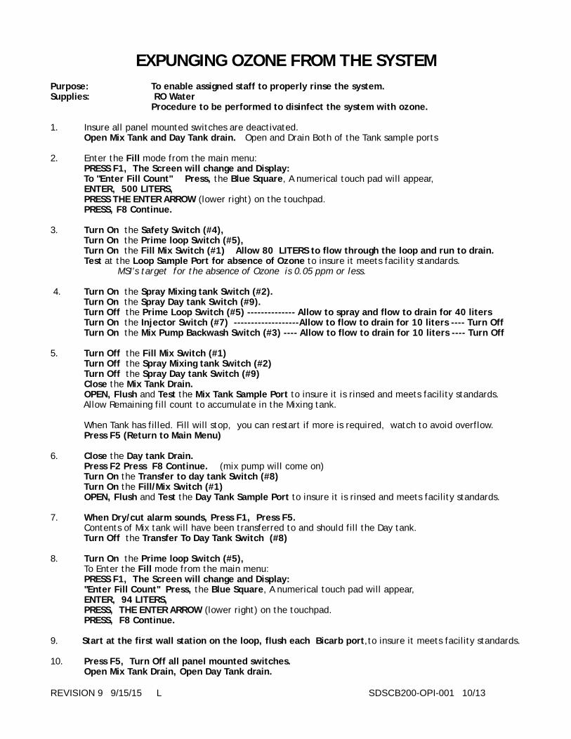
EXPUNGING OZONE FROM THE SYSTEM
Purpose: To enable assigned staff to properly rinse the system.
Supplies: RO Water
Procedure to be performed to disinfect the system with ozone.
1. Insure all panel mounted switches are deactivated. Open Mix Tank and Day Tank drain. Open and Drain Both of the Tank sample ports 2. Enter the Fill mode from the main menu: PRESS F1, The Screen will change and Display:
To "Enter Fill Count" Press, the Blue Square, A numerical touch pad will appear, ENTER, 500 LITERS,
PRESS THE ENTER ARROW (lower right) on the touchpad. PRESS, F8 Continue.
3. Turn On the Safety Switch (#4),
Turn On the Prime loop Switch (#5),
Turn On the Fill Mix Switch (#1) Allow 80 LITERS to flow through the loop and run to drain.
Test at the Loop Sample Port for absence of Ozone to insure it meets facility standards. MSI’s target for the absence of Ozone is 0.05 ppm or less. 4. Turn On the Spray Mixing tank Switch (#2).
Turn On the Spray Day tank Switch (#9).
Turn Off the Prime Loop Switch (#5) -------------- Allow to spray and flow to drain for 40 liters
Turn On the Injector Switch (#7) -------------------Allow to flow to drain for 10 liters ---- Turn Off
Turn On the Mix Pump Backwash Switch (#3) ---- Allow to flow to drain for 10 liters ---- Turn Off
5. Turn Off the Fill Mix Switch (#1)
Turn Off the Spray Mixing tank Switch (#2)
Turn Off the Spray Day tank Switch (#9)
Close the Mix Tank Drain. OPEN, Flush and Test the Mix Tank Sample Port to insure it is rinsed and meets facility standards. Allow Remaining fill count to accumulate in the Mixing tank. When Tank has filled. Fill will stop, you can restart if more is required, watch to avoid overflow. Press F5 (Return to Main Menu)
6. Close the Day tank Drain.
Press F2 Press F8 Continue. (mix pump will come on) Turn On the Transfer to day tank Switch (#8)
Turn On the Fill/Mix Switch (#1)
OPEN, Flush and Test the Day Tank Sample Port to insure it is rinsed and meets facility standards.
7. When Dry/cut alarm sounds, Press F1, Press F5.
Contents of Mix tank will have been transferred to and should fill the Day tank. Turn Off the Transfer To Day Tank Switch (#8)
8. Turn On the Prime loop Switch (#5),
To Enter the Fill mode from the main menu: PRESS F1, The Screen will change and Display:
"Enter Fill Count" Press, the Blue Square, A numerical touch pad will appear, ENTER, 94 LITERS,
PRESS, THE ENTER ARROW (lower right) on the touchpad. PRESS, F8 Continue.
9. Start at the first wall station on the loop, flush each Bicarb port,to insure it meets facility standards. 10. Press F5, Turn Off all panel mounted switches.
Open Mix Tank Drain, Open Day Tank drain.
REVISION 9 9/15/15! L ! ! ! ! ! ! SDSCB200-OPI-001 10/13!

END OF DAY RINSE PROCEDURE
Purpose: To enable assigned staff to properly rinse the system.
Supplies: RO Water
Procedure to be performed at the end of the operational day with no patients receiving
treatment.
1. Insure all panel mounted switches are deactivated. Open Mix Tank and Day Tank drain. Drain sample ports, LEAVE TANK DRAINS OPEN
2. Enter the Fill mode from the main menu: PRESS F1, The Screen will change and Display:
To "Enter Fill Count" Press, the Blue Square, A numerical touch pad will appear, ENTER, 500 LITERS,
PRESS THE ENTER ARROW (lower right) on the touchpad. PRESS, F8 Continue. Allow 20 Liters to run through the fill/mix plumbing to drain 3. Turn On the Injector Switch (#7)
Turn On the Mix Pump Backwash Switch (#3)
Allow 30 Liters to flow to drain (WATCH COUNT ON SCREEN)
4. Turn Off the Injector Switch (#7)
Turn Off the Mix Pump Backwash Switch (#3)
Turn On the Spray Mix Tank Switch (#2)
Turn On the Fill/Mix Switch (#1)
Allow 30 Liters to spray into the Mix Tank and run to drain. (WATCH COUNT ON SCREEN)
5. Turn On the Safety Switch (#4) Turn On the Spray Day tank Switch (#9)
Turn Off the Spray Mix Tank Switch (#2)
Allow 30 Liters to spray into the Day Tank and run to drain. ( WATCH COUNT ON SCREEN ) 6. Turn On the Transfer to Day Tank Switch (#8)
Turn Off the Spray Day tank Switch (#9)
Allow 20 Liters to spray into the Day Tank and run to drain. ( WATCH COUNT ON SCREEN )
7. Turn On the Prime Loop Switch (#5)
Turn Off the Transfer to Day Tank Switch (#8)
Turn On the Loop pump Backwash switch (10). For 10 Liters then Deactivate.
8. After 40 Liters have flushed through the loop and run to drain, start with the first wall station and
flush each wall station Bicarb port. Return to the Bicarb control, manipulate the Prime Loop Switch (#5), on/off a minimum of 6 times. This will clear the recirculation solenoid. and tubing. Turn On the Spray Day Tank (#9) for 20 more Liters.
9. When complete, the loop and Day Tank will be flushed, Close the day tank drain, Turn On the Transfer to Day Tank Switch (#8)
Turn Off the Prime Loop Switch (#5)
Allow at least 40 Liters to enter the Day Tank, OPEN, Flush and Test the Day Tank Sample Port to insure it is rinsed. Turn On the Loop Pump Switch (#6).
10. Close the Mix tank drain, Turn Off the Fill/Mix Switch (#1)
Turn Off the Transfer Switch (#8).
Allow at least 40 Liters to enter the Mix Tank, OPEN, Flush and Test the Mix Tank Sample Port to insure it is rinsed. PRESS, F5, Turn Off all remaining panel mounted switches, Open both drains
Don’t forget, if a switch is left on the solenoid will over heat and short out the system.
REVISION 9 9/15/15! L ! ! ! ! ! ! SDSCB200-OPI-001 11/13

END OF DAY RINSE PROCEDURE W/RECIRCULATIONPurpose: To enable assigned staff to properly rinse the system.
Supplies: RO Water
Procedure to be performed at the end of day with no patients receiving treatment.
1. Insure all panel mounted switches are deactivated. Open Mix Tank and Day Tank drain. Drain sample ports, LEAVE TANK DRAINS OPEN
2. Enter the Fill mode from the main menu: PRESS F1, The Screen will change and Display:
To "Enter Fill Count" Press, the Blue Square, A numerical touch pad will appear, ENTER, 500 LITERS,
PRESS THE ENTER ARROW (lower right) on the touchpad. PRESS, F8 Continue. Allow 20 Liters to run through the fill/mix plumbing to drain 3. Turn On the Injector Switch (#7)
Turn On the Mix Pump Backwash Switch (#3)
Allow 30 Liters to flow to drain (WATCH COUNT ON SCREEN)
4. Turn Off the Injector Switch (#7)
Turn Off the Mix Pump Backwash Switch (#3)
Turn On the Spray Mix Tank Switch (#2)
Turn On the Fill/Mix Switch (#1)
Allow 30 Liters to spray into the Mix Tank and run to drain. (WATCH COUNT ON SCREEN)
5. Turn On the Safety Switch (#4) Turn On the Spray Day tank Switch (#9)
Turn Off the Spray Mix Tank Switch (#2)
Allow 30 Liters to spray into the Day Tank and run to drain. ( WATCH COUNT ON SCREEN ) 6. Turn On the Transfer to Day Tank Switch (#8)
Turn Off the Spray Day tank Switch (#9)
Allow 20 Liters to spray into the Day Tank and run to drain. ( WATCH COUNT ON SCREEN )
7. Turn On the Prime Loop Switch (#5)
Turn Off the Transfer to Day Tank Switch (#8)
Turn On the Loop pump Backwash switch (10). For 10 Liters then Deactivate.
8. After 40 Liters have flushed through the loop and run to drain, start with the first wall station and
flush each wall station Bicarb port. Return to the Bicarb control, manipulate the Prime Loop Switch (#5), on/off a minimum of 6 times. This will clear the recirculation solenoid. and tubing. Turn On the Spray Day Tank (#9) for 20 more Liters.
9. When complete, the loop and Day Tank will be flushed, Close the day tank drain, Turn On the Transfer to Day Tank Switch (#8)
Turn Off the Prime Loop Switch (#5)
Allow at least 40 Liters to enter the Day Tank, OPEN, Flush and Test the Day Tank Sample Port to insure it is rinsed. Turn On the Loop Pump Switch (#6).
10. Close the Mix tank drain, Turn Off the Fill/Mix Switch (#1)
Turn Off the Transfer Switch (#8).
Allow at least 40 Liters to enter the Mix Tank, OPEN, Flush and Test the Mix Tank Sample Port to insure it is rinsed. PRESS, F5, Turn Off all panel mounted switches, Except Loop Pump Switch.
Open the Mix tank drain.
Don’t forget, if a switch is left on the solenoid will over heat and short out the system.Double Check to insure the Day Tank Drain Valve is closed. If the pump runs dry it will be ruined!
REVISION 9 9/15/15! L ! ! ! ! ! ! SDSCB200-OPI-001 12/13

EMERGENCY MIXING
ONLY IF THE CONTROL PANEL IS NOT FUNCTIONING
1. ! CLOSE THE WATER FILL VALVE ON THE WALL THAT LEADS TO THE ! BICARB MIXER.
2. ! DISCONNECT THE WATER HOSE FROM THE BACK OF THE MIXER.
3. ! PLACE THE HOSE INTO THE THE MIXING TANK.
4.! OPEN VALVE ON THE WALL TO FILL THE MIXER.
5. ! WHEN MIXING TANK IS FILLED TO THE DESIRED LEVEL,
6.! DISCONNECT THE MIXING PUMP PLUG FROM THE BACK OF THE ! MIXER CONTROL PANEL, PLUG INTO A EXTENSION CORD, ! THE !PUMP WILL COME ON, ADD BICARB POWDER.
7.! WHEN MIXED DISPENSE INTO JUGS FROM THE SAMPLE PORT IN ! ! FRONT OF THE !MIXER.
If the only problem is the Microprocessor and all the panel mounted switches are working you can proceed with the normal Prime and Transfer process, keeping the mixing pump plugged into the extension cord until transfer is complete.
REVISION 8 8/15/13! L ! ! ! ! ! ! ! SDSCB200-OPI-001 13/13

BICARB SYSTEMTROUBLE SHOOTINGGUIDE
!
MEDICAL SOLUTIONS INTERNATIONAL800-326-5275
REVISION 3 06/06/12! ! ! ! ! ! ! ! SDSCB200-TRB-001 1/4
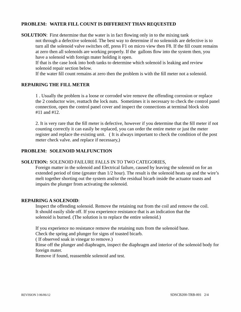
PROBLEM: !WATER FILL COUNT IS DIFFERENT THAN REQUESTED
SOLUTION: !First determine that the water is in fact flowing only in to the mixing tank ! !! not through a defective solenoid. The best way to determine if no solenoids are defective is to ! turn all the solenoid valve switches off, press F1 on micro view then F8. If the fill count remains ! at zero then all solenoids are working properly. If the gallons flow into the system then, you ! have a solenoid with foreign mater holding it open. ! If that is the case look into both tanks to determine which solenoid is leaking and review ! solenoid repair section below.! If the water fill count remains at zero then the problem is with the fill meter not a solenoid.
REPAIRING THE FILL METER !! 1 . Usually the problem is a loose or corroded wire remove the offending corrosion or replace ! the 2 conductor wire, reattach the lock nuts. Sometimes it is necessary to check the control panel ! connection, open the control panel cover and inspect the connections at terminal block slots ! #11 and #12.
! 2. It is very rare that the fill meter is defective, however if you determine that the fill meter if not ! counting correctly it can easily be replaced, you can order the entire meter or just the meter ! register and replace the existing unit. ( It is always important to check the condition of the post ! meter check valve. and replace if necessary,)
PROBLEM: !SOLENOID MALFUNCTION
SOLUTION:! SOLENOID FAILURE FALLS IN TO TWO CATEGORIES,! Foreign matter in the solenoid and Electrical failure, caused by leaving the solenoid on for an ! extended period of time (greater than 1/2 hour). The result is the solenoid heats up and the wire’s ! melt together shorting out the system and/or the residual bicarb inside the actuator toasts and ! impairs the plunger from activating the solenoid.
REPAIRING A SOLENOID: !! Inspect the offending solenoid. Remove the retaining nut from the coil and remove the coil. ! It should easily slide off. If you experience resistance that is an indication that the !! solenoid is burned. (The solution is to replace the entire solenoid.) ! ! ! ! !! If you experience no resistance remove the retaining nuts from the solenoid base.! ! ! Check the spring and plunger for signs of toasted bicarb. ! ( If observed soak in vinegar to remove.)! Rinse off the plunger and diaphragm, inspect the diaphragm and interior of the solenoid body for ! foreign mater. ! Remove if found, reassemble solenoid and test.
REVISION 3 06/06/12! ! ! ! ! ! ! SDSCB200-TRB-001 2/4

PROBLEM: ! ! CONTROL PANEL SOLENOID SWITCHES ARE ALL DEAD
SOLUTION:! ! ! FIRST THE CAUSE: Most likely a single or multiple solenoids were left ! ! ! ! on for an extended period of time. The solenoid got so hot it melted the ! ! ! ! coil cover and shorted out the system. When this happens a fuse will blow. ! ! ! ! (see fuse changing below). ! ! ! (systems manufactured after 01/01/12 have a circuit breaker, just switch back)! ! ! ! The solution is to first find the offending solenoid and replace it. ! ! ! ! (SEE ABOVE)! ! ! ! If it is not obvious then buy extra fuses and sacrifice a few by testing all ! ! ! ! the valve switches. Replace the fuse and turn on/off each solenoid until ! ! ! ! you blow the sacrificial fuse. ! ! ! ! Once the bad solenoid is located proceed to replace it.
REPLACING A FUSE: ! Remove and test both fuses located on the upper right of the ! ! ! ! inside control assembly. They are marked FU-1 & FU-2! ! ! ! The 6.25 amp (FU-2) fuse is the primary 24 volt solenoid fuse, ! ! ! ! red wires are attached to this fuse.! ! ! ! If one of the pumps has shorted out it will blow the 120 volt 20 amp fuse ! ! ! ! (FU-1). (black wires)! ! ! ! Remember that other things (like flooding any electrical connection) can ! ! ! ! cause ! fuses to blow.
PROBLEM: !MICROPROCESSOR MALFUNCTIONING
SOLUTION: !! ! This is extremely rare, and when it has happened there is an evident ! ! ! ! cause, (water damage, power fluctuation). With a power fluctuation the ! ! ! ! first and almost always effective solution is to unplug the entire bicarb ! ! ! ! system for 15 seconds, when energy is restored the unit will reset all of ! ! ! ! the defaults and function properly again. With water damage and the like ! ! ! ! the problem is more difficult to resolve. First attempt to dry every thing, ! ! ! ! at this point it is best to call for assistance (800-326-5275)
PROBLEM: !MIXING PUMP NOT WORKING OR LEAKING
SOLUTION: !! ! Is the pump shorting out (probably flooded) wait for it to dry or force ! ! ! ! drying. If shorted out beyond repair you will have to replace at least the ! ! ! ! motor, may be easier to replace the entire pump.! ! ! ! If leaking then it is most likely the Impeller housing, easy to replace and ! ! ! ! inexpensive (consider having one on your repair shelf). Here again it may ! ! ! ! be easier to replace the entire wet end kit, especially if your pump has ! ! ! ! some age on it (3+ years).
REVISION 3 06/06/12! ! ! ! ! ! ! SDSCB200-TRB-001 3/4

PROBLEM: !LOOP PUMP NOT WORKING PROPERLY
SOLUTION: !! ! Assuming that the loop filter (not on all models) on the return of the loop ! ! ! ! is not clogged, the best and easiest solution is to replace the wet end with ! ! ! ! a wet end kit. But we should also address the cause---bicarb precipitate is ! ! ! ! chewing up the impeller, you should increase the number of times! ! ! ! that you purge the system with a low pH cleaner (vinegar).
PROBLEM: !DRY CUT ALARM WILL NOT ALLOW MIXING OR TRANSFERRING
SOLUTION: !! ! The dry cut alarm monitors the flow from the mixing pump, if the pump ! ! ! ! is not functioning, the mixing tank is empty, or either the Fill/Mix or the ! ! ! ! Transfer solenoid are not functioning the Dry cut alarm will sound. ! ! ! ! Look into the tank with the Fill/Mix solenoid open and turn on the mix ! ! ! ! pump, if no water re-circulates through the tank, your Fill/Mix solenoid is ! ! ! ! bad (see solenoid repair) similarly check the transfer solenoid. These ! ! ! ! solenoids can also be checked by keying in the system to fill. Turn the ! ! ! ! Fill/Mix solenoid on, if water comes in the solenoid is not functioning. ! ! ! ! Test the Transfer solenoid in the same fashion. It is also possible that there ! ! ! ! is foreign matter in the flow sensor, you can remove and clean the flow ! ! ! ! sensor by sliding out the retaining bars and lifting out the vertical float, ! ! ! ! remove the foreign matter and replace.
PROBLEM: !FALSE LOW TANK ALARM
SOLUTION: !! ! Check the physical condition of the horizontal float switch by looking in ! ! ! ! the day tank and observing that it is still in tact. Next check that the wire ! ! ! ! connections are not corroded or separated.! ! ! ! Finally check in the control panel terminal strip slots #19 & 20. correct ! ! ! ! any obvious defect.! ! ! ! Failing that replace the float switch.
PROBLEM: !TAKES A LONG TIME TO TRANSFER OR PRIME
SOLUTION: !Change or clean the filter screens that are clogged.
REVISION 3 06/06/12! ! ! ! ! ! ! SDSCB200-TRB-001 4/4


COMPONENT LIST
1.! FILL/MIX SOLENOID2.! SPRAY MIX TANK SOLENOID3.! MIX PUMP BACKWASH SOLENOID4.! SAFETY SWITCH (NOT SHOWN ON DIAGRAM)5A.! PRIME LOOP SOLENOID5B.! LOOP DRAIN SOLENOID5C.! RECIRCULATION SOLENOID6.! LOOP RECIRCULATION PUMP7.! INJECTOR SOLENOID8.! TRANSFER TO DAY TANK SOLENOID9.! SPRAY DAY TANK SOLENOID10.! LOOP PUMP BACKWASH SOLENOIDF.! FILL SOLENOID (CONTROLLED BY MICROPROCESSOR)M.! WATER METER (CONTROLLED BY MICROPROCESSOR)MP.! MIXING PUMP (CONTROLLED BY MICROPROCESSOR)FS.! FLOW SENSOR (CONTROLLED BY MICROPROCESSOR)11.! SPRAY MIX TANK NOZZEL 12.! SPRAY DAY TANK NOZZEL13.! VENTURI INJECTOR 14.! TURBULENCE MULTIPLIER-EDUCTOR15.! CHECK VALVE 1.5" 16.! MIX TANK DRAIN VALVE 1.5"17.! BLACK 3/4" CHECK VALVE18.! CLEAR BOWL 3/4" STRAINER19.! CLEAR BOWL 1/2" STRAINER20.! BLACK 1/2" CHECK VALVE21.! LOOP PRESSURE GUAGE22.! LOOP PRESSURE ADJUSTMENT VALVE23.! LOW DAY TANK FLOAT SWITCH24.! SUB MICRON AIR FILTER25.! MIX TANK SAMPLE PORT26.! DAY TANK SAMPLE PORT27.! CHECK VALVE 1"28.! DAY TANK DRAIN 1.5"29.! TRU-UNION COUPLERS 3/4"30.! END OF LOOP PORT31.! TANK LID


ASSEMBLY INSTRUCTIONS DUAL TANK BICARB SYSTEM
1. PLACE THE THREE MAJOR SYSTEM COMPONENTS IN THE APPROXIMATE POSITION THAT THEY WILL INHABIT WHEN OPERATING.POSITION TANKS ON SIDES OF CONTROL PODIUM. WHEN FACING THE SYSTEM THE MIX TANK IS ON YOUR LEFT, AND THE DAY TANK IS ON YOUR RIGHT.
2. THE MIXING TANK CONTAINS ALL THE LOOSE COMPONENTS FOR ASSEMBLING THE SYSTEM, REMOVE THESE COMPONENTS AND PLACE TO THE SIDE. (SHIPPING THESE COMPONENTS INSIDE THE TANK INSURES THAT THEY ARE NOT LOST IN TRANSIT.)
3. FLIP THE MIXING TANK OVER AND TIGHTEN EVERY TRUE UNION FITTING AND VALVE. REPEAT THE PROCESS WITH THE DAY TANK. THIS WILL PREVENT LEAKS CAUSED BY VIBRATION DURING TRANSIT.
4. REMOVE THE MASKING TAPE THAT IS SECURING THE “O” RINGS ON THE PUMP FACES. INSPECT TO INSURE "O" RINGS ARE IN PLACE.
5. MOST IMPORTANT: YOU WILL FIND 4 NYLON BOLTS IN THE PACKAGE, THERE ARE HOLES IN THE INTERIOR LEGS OF BOTH TANKS THAT CORRESPOND WITH THREADED 1/2” HOLES IN THE PODIUM BASE. SCREW THE BOLTS THROUGH THE LEGS AND INTO THE BASE TO SECURE THE TANKS TO THE BASE.TIGHTEN THE TRUE UNIONS ON THE PUMPS.THE SYSTEM IS NOW ONE UNIT, CARE SHOULD BE EXERCISED WHEN MOVING THE SYSTEM.
NEVER ATTEMPT TO MOVE THE SYSTEM WITH WATER IN THE TANKS.
6. REMOVE THE MASKING TAPE THAT IS SECURING THE “O” RINGS ON THE EXPOSED TRUE UNIONS ON THE SOLENOIDS AND ON THE BACK OF EACH TANK. INSPECT TO INSURE ALL "O" RINGS ARE IN PLACE. MATCH UP THE PLUMBING EXTENSION ARMS ASSEMBLIES WITH THE CORRESPONDING TRUE UNIONS BY LETTER AND TIGHTEN.

7. THE SAME IS TRUE OF THE ONE PIECE OF BLUE TUBING WITH PARKER FAST -N-TIGHT FITTINGS ON EACH END. CHECK FOR “O” RINGS IN THE PARKER END PIECES.
8. ON THE INTERIOR RIGHT HAND SIDE OF THE BACK OF THE PODIUM YOU WILL FIND A LOOSE WIRE WITH A SQUARE SOLENOID PLUG. EXTEND THE WIRE AND PLUG OUT FROM THE PODIUM THROUGH THE MIX PUMP HOLE TO THE MIX PUMP BACKWASH SOLENOID AND ATTACH.
9. ON THE INTERIOR LEFT HAND SIDE OF THE BACK OF THE PODIUM YOU WILL FIND A LOOSE WIRE WITH A SQUARE SOLENOID PLUG. EXTEND THE WIRE AND PLUG OUT FROM THE PODIUM THROUGH THE PROVIDED PUMP HOLE TO THE LOOP PUMP BACKWASH SOLENOID AND ATTACH.
10. ON THE INTERIOR LEFT HAND SIDE OF THE BACK OF THE PODIUM YOU WILL FIND A LOOSE WIRE WITH REUSABLE BUTT CONNECTORS. ATTACH THESE TO THE LOOSE WIRES ON THE DAY TANK LOW TANK FLOAT SWITCH.
11. THE DRAIN MANIFOLD ASSEMBLY SHOULD BE CONNECTED TO THE OUT FLOW TRUE UNIONS ON THE TANKS, THE CONTROL PODIUM OUT FLOW ASSEMBLY IS PART OF THE MIX TANK DRAIN ASSEMBLY ( WATCH FOR “O” RINGS). THE DRAIN ENDS ARE INTERCHANGEABLE AND YOU CAN CHOOSE THE DRAIN FLOW DIRECTION BY USING THE TEE ON THE OUTFLOW END AND THE 90º ELBOW ON THE OTHER.
12. THE REMOTE ALARM LEADS (IF REQUIRED)ARE SUSPENDED FROM THE BACK LEFT OF THE INTERIOR TOP OF THE CONTROL PODIUM.
13. THE KIT ALSO CONTAINS 2 EA. .2 MICRON AIR FILTERS TO BE SCREWED IN THE PORTS ON THE TOP REAR OF THE MIX AND DAY TANKS. THESE SHOULD BE DATED AND EXCHANGED ANNUALLY.
14. THE KIT CONTAINS TWO 1/2” BALL VALVES TO BE SCREWED INTO THE SAMPLE PORT HOLES IN THE FRONT OF THE TANKS.
15. APPLY THE MIX AND DAY TANK DECALS TO THE FRONT OF THE TANKS.THE GALLON SCALE SHOULD BE APPLIED AFTER TEST FILLS.

16. REMOVE THE PARK FITTING FEMALE AND 3/4” HOSE FROM THE KIT. ATTACH THE HOSE TO THE PARK FITTING USING THE HOSE CLAMP PROVIDED. THERE IS ALSO A 3/4” NPT X 3/4” BARB AND HOSE CLAMP PROVIDED, FOR THE OTHER END OF THE HOSE TO CONNECT TO THERO WATER SERVICE.
17. IF OZONE IS USED ON SYSTEM:THE OZONE SYSTEM HOSE SHOULD CONNECTED TO THE VENTURI ASSEMBLY. OZONE SYSTEMS SHOULD BE CONNECTED TO THEIR OWN POWER SOURCE, UNLESS DESIGNED TO INTERFACE DIRECTLY WITH THIS SYSTEM. IN THAT CASE THE OZONE GENERATOR WOULD PLUG DIRECTLY INTO THE PROVIDED PLUG ON THE BACK OF THE CONTROL PODIUM.
18. IF THE OZONE VENTURI ASSEMBLY IS NOT TO BE USED, REMOVE THE ENTIRE VENTURI ASSEMBLY AND INJECTOR SOLENOID. IN THE 3/4” BULK HEAD IN THE TANK PLACE A 3/4” PLUG. IN THE 3/4” THREADED FEMALE ON THE DISTRIBUTION STEM PLACE A 3/4” PLUG. (CONSULT THE ATTACHED DRAWING.)

BiPro SDS CB200 Bicarbonate Mixing and Distribution System
Inservice Training Agenda
1. Review Physical components
Front of unit:Interior of mix tank, spray nozzle, eductorInterior of day tank, spray nozzle, low tank floatSample portsDrain valvesEnd of loop drain pocket
Back of unit:Mixing pump, loop re-circulation pump
solenoids, meter, flow sensorre-circulation control
Control panel:Rocker switches Panel view 300
2. Explanation of operating instructions
Mixing InstructionsRinsing instructionsDisinfection instructions
3. Demonstration of instructions
Mixing InstructionsRinsing instructionsDisinfection instructions
4. Ozone review
Purpose and useDemonstration of instructions
5. Questions and Answers
Facility_______________Date_____________ MSI Instructor______________________
Attedees listed on attached page: page 1 of 2

Facility_______________Date_____________
Inservice Training Attendees:
Print Name Signature
_________________________ ________________________
_________________________ ________________________
_________________________ ________________________
_________________________ ________________________
_________________________ ________________________
_________________________ ________________________
_________________________ ________________________
_________________________ ________________________
_________________________ ________________________
_________________________ ________________________
_________________________ ________________________
_________________________ ________________________
_________________________ ________________________
_________________________ ________________________
_________________________ ________________________
_________________________ ________________________
page 2 of 2