operator's/ - arctic cat operator’s manual, ... installed spring rate chart ... lighting coil...
TRANSCRIPT

2011
TMSHARE OUR PASSION.
Operator's/Performance Manual
Sno Pro 500


FOREWORD
Congratulations! You have chosen a quality Arctic Cat Snowmobile designed and manufactured to give depend-able service. Be sure, as the owner/operator of an Arctic Cat Snowmobile, to become thoroughly familiar with itsbasic operation, maintenance, and off-season storage procedures. Read this manual and the accompanying Snow-mobile Safety Handbook before operating the snowmobile to ensure safe and proper use of your new Arctic CatSnowmobile. Always operate the snowmobile within your level of skill and current terrain conditions.
The Operator’s Manual, Snowmobile Safety Handbook, and snowmobile decals display the words Warning, Cau-tion, and Note to emphasize important information. The symbol ! WARNING identifies personal safety-related information. Be sure to follow the directive because it deals with the possibility of severe personal injury oreven death. A CAUTION identifies unsafe practices which may result in snowmobile-related damage. Followthe directive because it deals with the possibility of damaging part or parts of the snowmobile. The symbolNOTE: identifies supplementary information worthy of particular attention.
This manual covers operator-related maintenance, operating instructions, and off-season storage instructions. Ifmajor repair or service is ever required, contact an authorized Arctic Cat Snowmobile dealer for professional ser-vice.
At the time of publication, all information and illustrations were technically correct. Some illustrations used in thismanual are used for clarity purposes only and are not designed to depict actual conditions. Because Arctic Cat Inc.constantly refines and improves its products, no retroactive obligation is incurred.
This Operator’s Manual should be considered a permanent part of the snowmobile and must remain with the snow-mobile at the time of resale. If the snowmobile changes ownership more than once, contact Arctic Cat Inc., ServiceDepartment, P.O. Box 810, Thief River Falls, MN 56701, for proper registration information.
Every Arctic Cat Snowmobile meets or exceeds the standards of the Snowmobile Safety and Certification Commit-tee and displays the SSCC decal. Arctic Cat endorses and encourages the safe use of all snowmobiles. Always weara helmet and eye protection. Drive with caution, observe all state and local regulations, and respect the rights ofothers. ISMA members like Arctic Cat do their part to improve trails, sponsor events, and generally support thesport of snowmobiling. As a member of the National Snowmobile Foundation, Arctic Cat Inc. promotes snowmo-biling through education, charity, and research programs.
© 2010 Arctic Cat Inc.
Printed in U.S.A. September 2010

If the snowmobile is purchased through the Team Arctic Race Department Racing Program, there is no warranty.
Reference Information
Write the appropriate information for your Arctic CatSnowmobile in the spaces below. Always use thesenumbers when referring to your snowmobile.
Model: ____________________________________
Date of Purchase: ____________________________
Vehicle Identification Number: __________________
Engine Serial Number: ________________________
Your Arctic Cat Dealer: ________________________
Address: ____________________________________
Phone: _____________________________________
! WARNINGThis snowmobile is a very high performance snowmo-bile. Because it does accelerate rapidly and is capableof very high speeds, it should not be operated by anovice or an inexperienced operator. Never acceleraterapidly or drive at high speed beyond the limits of visi-bility or without being totally familiar with the terrainand what lies in front of you. Obey speed limits andnever operate at speeds that do not allow adequatemaneuvering and stopping distances. Read and studythe entire Operator’s Manual and Safety Handbook.Failure to follow this warning could result in personalinjury to yourself or others.
PARTS AND ACCESSORIES
When in need of replacement parts, oil, or accesso-ries for your Arctic Cat Snowmobile, be sure to onlyuse GENUINE ARCTIC CAT PARTS, OIL, ANDACCESSORIES. Only genuine Arctic Cat parts, oil,and accessories are engineered to meet the standardsand requirements of your Arctic Cat Snowmobile.For a complete list of accessories, refer to the currentArctic Cat Accessory Catalog.
To aid in service and maintenance procedures on thissnowmobile, an Illustrated Parts Manual is availablethrough your local Arctic Cat Snowmobile dealer.

TABLE OF CONTENTS
Specifications/Charts/Patterns/Diagrams.............. 1-15Engine Specifications ............................................. 1General Specifications............................................ 1Engine Torque Specifications.................................. 1Engine Torque Patterns........................................... 1Torque Conversions (ft-lb/N-m)............................... 2Tightening Torque (General Bolts) .......................... 2Electrical Specifications .......................................... 2Oil Consumption Specifications .............................. 2Component Voltage/Resistance Chart - Coolant
Temperature......................................................... 3Component Voltage/Resistance Chart - Air
Temperature......................................................... 4Crankshaft Runout/Repair Specifications ............... 5Cylinder Head Volume Specifications ..................... 5Drive System Specifications ................................... 6Driven Pulley Optional Components ....................... 6Drive Clutch Spring Chart ....................................... 7Drive Clutch Cam Arms .......................................... 7Chain Case Performance Calibrations.................... 8Chains and Sprockets............................................. 9EFI Specifications ................................................... 9Throttle Valve Angle Specifications......................... 9Rear Spring Selection Chart ................................... 9Installed Spring Rate Chart .................................. 10Front Suspension Sway Bar (Optional)................. 10Ski Shock Springs................................................. 10Rebuildable Shock Tools Required ....................... 10Valve Stacks/Specifications .................................. 11Rebuildable Shock Accessory Part Numbers ....... 12Fraction/Decimal Conversion Chart ...................... 13Drill Bit Sizes (Number) Chart............................... 13MM/IN. Conversion Chart ..................................... 13Wiring Diagram (Hood) ......................................... 16Wiring Diagram (Ignition/Main) ............................ 17
Setup Instructions ............................................... 19-26Removing Snowmobile From Crate/
Handlebar Assembly ......................................... 19Installing Windshield ............................................. 19Installing Spindle/A-Arm ....................................... 19Installing Front Shock Absorbers .......................... 19Installing Skis........................................................ 19Installing Sway Bar (Optional)............................... 20Track Tension/Track Alignment .............................. 20Ski Alignment........................................................ 21Handlebar Alignment ............................................ 23Handlebar Height Adjustment............................... 23Steering Speed Ratio Adjustment......................... 24Drive Belt .............................................................. 24Hydraulic Brake System........................................ 25Recommended Gasoline ...................................... 25Checking Headlight Aim........................................ 25Preoperation Checks ............................................ 25Test Ride ............................................................... 26
General Information............................................. 26-31Snowmobile Identification ..................................... 26Control Locations .................................................. 26Engine Break-In .................................................... 26Speedometer/Tachometer..................................... 26Diagnostic Codes.................................................. 27Handlebar Tilt ........................................................ 27Rear Bumper......................................................... 27Exhaust System .................................................... 27Air-Intake Silencer................................................. 27Liquid Cooling System .......................................... 27Drive Belt............................................................... 28Drive Clutch and Driven Pulley ............................. 28Drive Clutch/Driven Pulley Alignment ................... 28Drive Chain Tension .............................................. 28EFI System ........................................................... 29Shock Absorbers................................................... 31Track Studs............................................................ 31Towing ................................................................... 31
Operating Instructions ......................................... 31-33Starting and Stopping Engine ............................... 31Braking.................................................................. 32Emergency Stopping............................................. 33
Lubrication........................................................... 33-34Chain Case ........................................................... 33Front Suspension .................................................. 34Rear Suspension .................................................. 34
Maintenance........................................................ 35-77Periodic Maintenance Checklist ............................ 35Pre-Race/Practice Checklist ................................. 36Engine................................................................... 36Individual EFI Components................................... 58Individual Fuel System Components .................... 63Spark Plugs........................................................... 67Track Drive ............................................................ 67Hydraulic Brake..................................................... 68Brake Fluid ............................................................ 68Checking Brake Lever Travel ................................. 68Bleeding Brake System......................................... 69Checking/Changing Brake Pads ........................... 69Drive Belt............................................................... 70Driven Pulley ......................................................... 71Ski Shock Absorber Springs ................................. 73Servicing Zero Pro Shock Absorbers
(Ski Shock)......................................................... 73Adjusting Rear Transfer Adjuster Cams ................ 76Lights .................................................................... 76Ski Wear Bar ......................................................... 77Rail Wear Strip ...................................................... 77
Performance Tips ..................................................... 78Preparation For Storage...................................... 78-79Preparation After Storage......................................... 79Genuine Arctic Cat Products ............................... 79-80Special Tools ....................................................... 80-90

NOTES

Engine Specifications
General Specifications
Engine Torque Specifications
*With Blue Loctite #243
Engine Torque Patterns
0738-204
0742-746
ITEM 500 ccEngine Model Number AX50L7
Displacement 499 cc
No. of Cylinders 2
Bore x Stroke 71 x 63
Compression Ratio 6.38:1
Cooling System Liquid
Fuel Mixture Oil Injection
Ignition Timing (Engine Warm) 12° @ 2000 RPM0.034 in.
Spark Plug (NGK) BR9EYA
Spark Plug Gap 0.028-0.031 in.
Piston Skirt/Cylinder Clearance 0.0030-0.0041 in.
Piston Ring End Gap 0.008-0.016 in.
Cylinder Trueness Limit 0.004 in.
Piston Pin Diameter 0.8659-0.8661 in.
Piston Pin Bore Diameter 0.8661-0.8665 in.
Connecting Rod Small End Bore 1.0631-1.0634 in.
Connecting Rod Radial Play 0.0001-0.0008 in.
Crankshaft Runout (t.i.r.) 0.002 in.
Crankshaft End Play 0.002-0.004 in.
Reed Stopper Height 0.315 in.
Chassis Length (Overall) 299.0 cm (117.7 in.)
Height (Overall) 115.5 cm (45.5 in.)
Width (Overall) 121.9 cm (48 in.)
Spindle Center-to-CenterDistance (Stance)
108.0 cm (42.5 in.)
Dry Weight (approx) 204.1 kg (450 lb)
Gas Tank Capacity 38.2 l (10.1 U.S. gal.)
Chain Case Lubricant Level 236 ml (8 fl oz)
Gasoline (Recommended) 87 Octane (minimum)Non-Oxygenated
Pre-Mix Oil (32:1 Ratio) Arctic Cat Formula 50 Injection Oil
Chain Case Lubricant Transmission Lube
Suspension Grease All-Temperature
Brake Fluid High-Temp DOT 3
Taillight/Brakelight Bulb p/n 0409-056
Headlight Bulb p/n 0409-073/0409-045
Cooling System Capacity 3.81 l (4.0 U.S. qt)
Starting System Manual Recoil
Oil Capacity 4.75 qts
ITEM VALUECylinder Head 6 mm 96 in.-lb
8 mm 19 ft-lb
Cylinder Base 14-44 ft-lb (3 Steps)
Flywheel 50 ft-lb
Exhaust Manifold 17 ft-lb
Intake Flange 96 in.-lb
Crankcase 6 mm 96 in.-lb
10 mm 13-37 ft-lb (2 Steps)
Spark Plug 19 ft-lb
MAG Housing 18 ft-lb
Oil-Injection Pump* 96 in.-lb
Water Pump Impeller* 108 in.-lb
Water Pump Cover 96 in.-lb
Thermostat Cap 96 in.-lb
Stator Plate* 96 in.-lb
Timing Sensor* 48 in.-lb
Stator* 96 in.-lb
Starter Pulley 19 ft-lb
Recoil Starter 96 in.-lb
Drive Clutch 50-55 ft-lb
1
0738-201
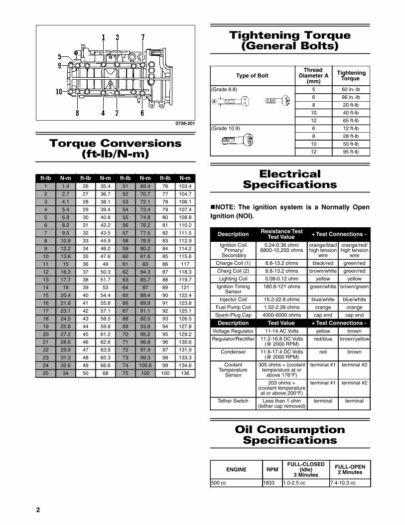
Torque Conversions(ft-lb/N-m)
Tightening Torque (General Bolts)
Electrical Specifications
NOTE: The ignition system is a Normally OpenIgnition (NOI).
Oil Consumption Specifications
ft-lb N-m ft-lb N-m ft-lb N-m ft-lb N-m1 1.4 26 35.4 51 69.4 76 103.4
2 2.7 27 36.7 52 70.7 77 104.7
3 4.1 28 38.1 53 72.1 78 106.1
4 5.4 29 39.4 54 73.4 79 107.4
5 6.8 30 40.8 55 74.8 80 108.8
6 8.2 31 42.2 56 76.2 81 110.2
7 9.5 32 43.5 57 77.5 82 111.5
8 10.9 33 44.9 58 78.9 83 112.9
9 12.2 34 46.2 59 80.2 84 114.2
10 13.6 35 47.6 60 81.6 85 115.6
11 15 36 49 61 83 86 117
12 16.3 37 50.3 62 84.3 87 118.3
13 17.7 38 51.7 63 85.7 88 119.7
14 19 39 53 64 87 89 121
15 20.4 40 54.4 65 88.4 90 122.4
16 21.8 41 55.8 66 89.8 91 123.8
17 23.1 42 57.1 67 91.1 92 125.1
18 24.5 43 58.5 68 92.5 93 126.5
19 25.8 44 59.8 69 93.8 94 127.8
20 27.2 45 61.2 70 95.2 95 129.2
21 28.6 46 62.6 71 96.6 96 130.6
22 29.9 47 63.9 72 97.9 97 131.9
23 31.3 48 65.3 73 99.3 98 133.3
24 32.6 49 66.6 74 100.6 99 134.6
25 34 50 68 75 102 100 136
Type of BoltThread
Diameter A(mm)
TighteningTorque
(Grade 8.8) 5 60 in.-lb
6 96 in.-lb
8 20 ft-lb
10 40 ft-lb
12 65 ft-lb
(Grade 10.9) 6 12 ft-lb
8 28 ft-lb
10 50 ft-lb
12 95 ft-lb
Description Resistance TestTest Value + Test Connections -
Ignition CoilPrimary/
Secondary
0.24-0.36 ohm/6800-10,200 ohms
orange/blaclhigh tension
wire
orange/red/high tension
wire
Charge Coil (1) 8.8-13.2 ohms black/red green/red
Charg Coil (2) 8.8-13.2 ohms brown/white green/red
Lighting Coil 0.08-0.12 ohm yellow yellow
Ignition TimingSensor
180.8-121 ohms green/white brown/green
Injector Coil 15.2-22.8 ohms blue/white blue/white
Fuel Pump Coil 1.52-2.28 ohms orange orange
Spark-Plug Cap 4000-6000 ohms cap end cap end
Description Test Value + Test Connections -Voltage Regulator 11-14 AC Volts yellow brown
Regulator/Rectifier 11.2-16.8 DC Volts(@ 2000 RPM)
red/blue brown/yellow
Condenser 11.6-17.4 DC Volts(@ 2000 RPM)
red brown
CoolantTemperature
Sensor
305 ohms + (coolanttemperature at or
above 176°F)
terminal #1 terminal #2
203 ohms +(coolant temperatureat or above 200°F)
terminal #1 terminal #2
Tether Switch Less than 1 ohm(tether cap removed)
terminal terminal
ENGINE RPMFULL-CLOSED
(Idle)3 Minutes
FULL-OPEN2 Minutes
500 cc 1833 1.0-2.5 cc 7.4-10.3 cc
2

Component Voltage/Resistance Chart -
Coolant Temperature
TEMP/C TEMP/F VOLTAGE OHMS110 230 0.115 129
108 226 0.129 137
106 223 0.143 145
104 219 0.157 153
102 216 0.171 161
100 212 0.185 169
98 208 0.192 180
96 205 0.199 191
94 201 0.206 202
92 198 0.213 213
90 194 0.220 224
88 190 0.235 240
86 187 0.250 256
84 183 0.265 273
82 180 0.280 289
80 176 0.295 305
78 172 0.317 327
76 169 0.339 349
74 165 0.361 371
72 162 0.383 393
70 158 0.405 415
68 154 0.438 445
66 151 0.471 475
64 147 0.504 505
62 144 0.537 535
60 140 0.570 565
58 136 0.598 609
56 133 0.626 653
54 129 0.654 697
52 126 0.682 741
50 122 0.710 785
48 118 0.759 849
46 115 0.808 913
44 111 0.857 977
42 108 0.906 1041
40 104 0.955 1105
38 100 1.023 1214
36 97 1.091 1323
34 93 1.159 1432
32 90 1.227 1541
30 86 1.295 1650
TEMP/C TEMP/F VOLTAGE OHMS28 82 1.377 1800
26 79 1.459 1950
24 75 1.541 2100
22 72 1.623 2250
20 68 1.705 2400
18 64 1.806 2670
16 61 1.907 2940
14 57 2.008 3210
12 54 2.109 3480
10 50 2.210 3750
8 46 2.327 4170
6 43 2.444 4590
4 39 2.561 5010
2 36 2.678 5430
0 32 2.795 5850
-2 28 2.901 6510
-4 25 3.007 7170
-6 21 3.113 7830
-8 18 3.219 8490
-10 14 3.325 9150
-12 10 3.421 9422
-14 7 3.517 9694
-16 3 3.613 9966
-18 -0.4 3.709 10238
-20 -4 3.805 10510
-22 -8 3.885 13688
-24 -11 3.965 16866
-26 -15 4.045 20044
-28 -18 4.125 23222
-30 -22 4.205 26400
-32 -26 4.267 30520
-34 -29 4.329 34640
-36 -32 4.391 38760
-38 -36 4.453 42880
-40 -40 4.515 47000
-42 -44 4.553 55100
-44 -47 4.591 63200
-46 -51 4.629 71300
-48 -54 4.667 79400
-50 -58 4.705 87500
3

Component Voltage/Resistance Chart - Air Temperature
TEMP/C TEMP/F VOLTAGE OHMS100 212 0.113 555
98 208 0.121 595
96 205 0.128 635
94 201 0.136 675
92 198 0.143 715
90 194 0.151 755
88 190 0.162 819
86 187 0.173 883
84 183 0.184 947
82 180 0.195 1011
80 176 0.206 1075
78 172 0.222 1160
76 169 0.238 1245
74 165 0.253 1330
72 162 0.269 1415
70 158 0.285 1500
68 154 0.308 1640
66 151 0.331 1780
64 147 0.353 1920
62 144 0.376 2060
60 140 0.399 2200
58 136 0.432 2410
56 133 0.465 2620
54 129 0.498 2830
52 126 0.531 3040
50 122 0.564 3250
48 118 0.612 3595
46 115 0.659 3940
44 111 0.707 4285
42 108 0.754 4630
40 104 0.802 4975
38 100 0.869 5490
36 97 0.937 6005
34 93 1.004 6520
32 90 1.072 7035
30 86 1.139 7550
TEMP/C TEMP/F VOLTAGE OHMS28 82 1.230 8540
26 79 1.322 9530
24 75 1.413 10520
22 72 1.505 11510
20 68 1.596 12500
18 64 1.716 14020
16 61 1.836 15540
14 57 1.955 17060
12 54 2.075 18580
10 50 2.195 20100
8 46 2.323 23060
6 43 2.452 26020
4 39 2.580 28980
2 36 2.709 31940
0 32 2.837 34900
-2 28 2.969 39940
-4 25 3.101 44980
-6 21 3.233 50020
-8 18 3.365 55060
-10 14 3.497 60100
-12 10 3.610 76080
-14 7 3.722 92060
-16 3 3.835 108040
-18 -0.4 3.947 124020
-20 -4 4.060 140000
-22 -8 4.142 156000
-24 -11 4.224 172000
-26 -15 4.306 188000
-28 -18 4.388 204000
-30 -22 4.470 220000
-32 -26 4.522 261000
-34 -29 4.574 302000
-36 -32 4.625 343000
-38 -36 4.677 384000
-40 -40 4.729 425000
4

Crankshaft Runout/Repair Specifications
For those who have crankshaft work sent out to another shop, it is advisable to provide them with this information.
To use the specifications, first refer to the drawing; then find the letter which indicates the specification and refer tothe chart below the illustration. Specifications are called out in both millimeters and inches.
NOTE: We have given the proper location for checking crankshaft runout as the very edge of the straightportion of the shaft where the oil seal makes contact. From the illustration, note that Arctic Cat has calledout three check points: at either end, out on the taper as shown, and also on the center bearing race. Thecrankshaft is still supported on the outer bearings using V blocks. The maximum runout shouldn’t exceed0.05 mm (0.002 in.).
728-144A
NOTE: Measure in from the shaft end the specified amount when checking runout at points D and F.When checking runout in the center, place indicator on center of bearing as shown at point E. Maximumrunout at any of the 3 measuring points is ±0.05 mm (0.002 in.).
Cylinder Head Volume Specifications
Engine Bore XStroke A B C G Runout D
and F Point(± .002)
500 cc mm(in.)
71 x 63(2.795 x 2.480)
114.6 ± 0.15(4.515 ± 0.006)
66.5 ± 0.15(2.618 ± 0.006)
113.4 ± 0.4(4.465 ± 0.015)
26.9(1.062)
D 5(0.196)
F 5(0.196)
Engine type Squish-Gap500 cc 0.059 in.
5

Drive System Specifications
* ± 0.188 in.** 20 (p/n 1602-413/46 (p/n 2602-074)
NOTE: For optional drive system components, refer to the Optional Components chart below.
Driven PulleyOptional Components
*Lightweight driven pulley only.
MODELDRIVE CLUTCH DRIVE SPRING CAM ARM DRIVEN PULLEY DRIVEN SPRING
P/N P/N COLOR P/N GRAMS P/N SPRING COLORSno Pro 500 0746-232 0646-229 Yellow/
White0746-826 64.0 0726-297 0648-790 Black/Light Blue
MODELDRIVE BELT ENGAGEMENT/
MAXIMUM RPMGEARRATIO
CHAIN TORQUEBRACKET
P/N Length* Width* PITCH P/N DEGREESno Pro 500 0627-047 43.547 in. 1.448 in. 3500-6000/
7900-800020/46**
(15/13 wide)74
(15 wide)1602-774 40/38
Driven PulleyTorqueBracket Degree Spring Color Spring
Rate0648-779* 58-46-36/
58-48-360648-749 Black/White 160/260
0648-775* 52-42-46/52-44-46
0648-702 Red/Black 140/240
0648-773* 70-44-32/68-48-46
0648-784 Black 155/222
0648-710 70-50-46/68-48-46
0648-790 Black/Light Blue
180/260
0648-737 70-44-32/68-48-46
0648-792 Black/Orange 180/280
0648-719 68-42-34/68-44-32
— — —
0648-789* 68-48-36/64-48-41
— — —
0648-791* 48-44-36/48-42-36
— — —
6

Drive Clutch Spring Chart
* Titanium
Drive Clutch Cam Arms
NOTE: All listed cam arms are w/set screw.
** Notched Cam Arm
ARCTIC CAT DRIVE CLUTCH SPRING CHART
p/n Rate @ 2 9/16 in.Rate @ 1 5/16 in. ColorLIGHT 0646-148 53 lb 224 lb Blue
0646-150 72 lb 188 lb Silver0646-149 74 lb 228 lb Red0646-376 75 lb 275 lb Gold0646-147 114 lb 267 lb Yellow/Green0646-373* 114 lb 267 lb Yellow/Green0646-155 121 lb 240 lb Purple0646-229 122 lb 285 lb Yellow/White0646-379* 122 lb 285 lb Yellow/White0646-035 143 lb 286 lb Orange/Black0646-248 143 lb 290 lb Orange/White0646-367 143 lb 250 lb Black0646-435 143 lb 290 lb Orange
StripeHEAVY 0646-684 158 lb 290 lb Black
ARCTIC CAT DRIVE CLUTCH CAM ARMS
p/n Grams p/n Grams0746-627 84.8 0746-703 68.00746-629 75.0 0746-704 51.0**0746-658 49.0** 0746-708 51.00746-661 52.0 0746-710 72.00746-662 52.0 0746-712 77.00746-663 52.0 0746-713 48.00746-664 52.0 0746-715 77.00746-666 55.0 0746-716 73.00746-668 55.0 0746-742 83.50746-669 60.0 0746-744 50.00746-670 65.0 0746-748 46.00746-671 70.0 0746-749 65.00746-672 75.0 0746-771 44.00746-673 80.0 0746-772 42.00746-676 70.0 0746-773 85.00746-678 55.0 0746-786 63.00746-687 57.0 0746-787 44.00746-689 69.0 0746-788 47.50746-690 47.0 0746-789 42.00746-691 44.0 0746-791 60.00746-692 50.0 0746-792 47.00746-694 63.0 0746-793 63.00746-695 67.0 0746-821 82.00746-696 63.0 0746-822 71.50746-699 66.0 0746-824 66.00746-701 49.0 0746-825 50.00746-702 58.0 0746-826 64.0**
7

Chain Case Performance Calibrations
NOTE: The following table should be used as a guide only.
RPM x Ratio x 0.0225 x 1.12 = MPH
RPM x Ratio x 0.0213 x 1.12 = MPH
RPM x Ratio x 0.02368 x 1.12 = MPH *Production
NOTE: The above gearing options are combinations which allow acceptable chain tension. Any othercombinations will not allow acceptable chain tension.
Drive Sprocket Chain Case Performance Specifications RPM (Engine)
8-Tooth(3.00 Pitch)
Sprockets Ratio Chain Pitch 7400 7800 8000 8200 870020/46 0.435 74 81.1 85.5 87.7 89.9 95.4
20/45 0.444 74 82.8 87.3 89.5 91.7 97.3
21/45 0.467 74 87.1 91.8 94.1 96.5 102.4
19/40 0.475 70 88.6 93.4 95.8 98.2 100.5
21/41 0.512 72 95.5 100.6 103.2 105.8 112.3
20/39 0.513 70 95.7 100.8 103.4 106.0 112.5
22/41 0.537 72 100.1 105.5 108.2 110.9 113.6
22/40 0.550 72 102.6 108.1 110.9 113.7 120.6
23/40 0.575 72 107.2 113.0 115.9 118.8 121.7
23/39 0.590 72 110.0 116.0 119.0 121.9 129.4
24/39 0.615 72 115.0 120.9 124.0 127.1 134.8
Drive Sprocket Chain Case Performance Specifications RPM (Engine)
9-Tooth(2.52 Pitch)
Sprockets Ratio Chain Pitch 6000 7000 8000 9000 10,00020/46 0.435 74 62.3 72.6 83.0 93.4 103.8
20/45 0.444 74 63.6 74.1 84.7 95.3 105.9
21/45 0.467 74 66.8 78.0 89.1 100.3 111.4
19/40 0.475 70 68.0 79.3 90.7 102.0 113.3
21/41 0.512 72 73.3 85.5 97.7 109.9 122.1
20/39 0.513 70 73.4 85.7 97.9 110.1 122.4
22/41 0.536 72 76.7 89.5 102.3 115.1 127.9
22/40 0.550 72 78.7 91.8 105.0 118.1 131.2
23/40 0.575 72 82.3 96.0 109.7 123.5 137.2
23/39 0.590 72 84.5 98.5 112.6 126.7 140.8
24/39 0.615 72 88.1 102.7 117.4 132.1 146.7
Drive Sprocket Chain Case Performance Specifications RPM (Engine)
10-Tooth*(2.52 Pitch)
Sprockets Ratio Chain Pitch 7400 7800 8000 8200 8400 870020/46* 0.435 74 85.4 90.0 92.3 94.7 97.0 100.4
20/45 0.444 74 87.1 91.8 94.2 96.6 99.0 102.4
21/45 0.467 74 91.6 96.6 99.1 101.6 104.1 107.8
19/40 0.475 70 93.2 98.3 100.8 103.3 105.8 109.6
21/41 0.512 72 100.5 105.9 108.6 111.3 114.1 118.1
20/39 0.513 70 100.7 106.1 108.8 111.6 114.3 118.4
22/41 0.537 72 105.3 111.0 113.8 116.7 119.5 123.8
22/40 0.550 72 108.0 113.8 116.7 119.6 122.5 126.9
23/40 0.575 72 112.8 118.9 122.0 125.0 128.1 132.7
23/39 0.590 72 115.8 122.0 125.2 128.3 131.4 136.1
24/39 0.615 72 120.7 127.2 130.5 133.7 137.0 142.0
8

Chains and Sprockets
* Aluminum
** PTL
EFI Specifications
Throttle Valve Angle Specifications
Rear SpringSelection Chart
Below is a list of rear suspension springs and specifi-cations. This chart was compiled to assist techniciansin fine-tuning the Arctic Cat rear suspension when theoriginal springs are not optimum for the conditionsand a softer or firmer ride is desired.
A longer spring in areas (D) and (E) can be selected ifcut off to match the original spring. The replacementspring must match the original spring in areas (C), (D),and (E).
0730-218
* Production
NOTE: The wire diameter and length of the springhave a large influence over the valving of theshocks.
WIDE CHAIN (13 Link)PITCH P/N
70 1602-41972 1602-42074 1602-473
WIDE CHAIN (15 Link)70 1602-57872 1602-77374 1602-774
WIDE CHAIN (17 Link)70 1602-80572 1602-90474 1602-806
WIDE SPROCKET (w/13 Link Chain)NUMBER OF TEETH INSIDE SPLINE P/N
19 15 1602-41220 15 1602-41321 15 2602-21522 15 2602-24423 15 2602-21624 15 2602-25439 15 1602-41439 16 2602-21740 15 1602-41540* 16 2602-24540 16 2602-21841 15 1602-41641 16 2602-21942 15 1602-41743 15 1602-41844 15 1602-48145 16 2602-22345 15 1602-48246 16 2602-07446* 16 2602-224
WIDE SPROCKET (w/15 Link Chain)19 15 1602-54820 15 1602-60021 15 1602-68523 15 2602-10939 16 1602-68642 16 1602-68743 16 1602-54944 16 1602-68845 16 1602-68946 16 1602-690
WIDE SPROCKET (w/17 Link Chain)19 15 1602-79620 15 1602-73521 15 1602-79743 16 1602-73444 16 1602-80245 16 1602-80346 16 1602-804
46** 16 1602-92546* 16 1602-811
Fuel Pressure 42.8-47.3 psi
MODEL TPS TOOL(DC VOLTS)
ANALYZER TOOL(DC VOLTS)
500 cc Idle 0.710-0.818 0.710-0.818
P/NWire
Diameter(A)
Angle(B)
Numberof
Coils
CoilWidth
(C)
Length(D)
Length(E)
Degree(In lb)
1704-916/917
.405 120° 5.90 3.20 15.62 4.70 24
1704-382/383*(Light)
.359 90° 5.75 3.00 15.62 4.60 17
1704-384/385(Heavy)
.375 90° 5.75 3.00 15.62 4.60 20
9

Installed Spring Rate Chart
Front SuspensionSway Bar (Optional)
NOTE: Swar Bar Mounting Kit (p/n 5639-635).
Ski Shock Springs
* Production
Rebuildable Shock Tools Required
P/N
Suspension FullyExtended
(In lb - AdjusterSet 1 & 1)
Suspension FullyExtended
(In lb - AdjusterSet 3 & 3)
1704-382/383 1360 1700
1704-384/385 1600 2000
1704-916/917 482 964
P/N
Suspension FullyCollapsed
(In lb - AdjusterSet 1 & 1)
Suspension FullyCollapsed
(In lb - AdjusterSet 3 & 3)
1704-382/383 3740 4080
1704-384/385 4400 4800
1704-916/917 3856 4338
PART NUMBER(Sway Bar)
PART NUMBER(Bushing)
DESCRIPTION
4639-961 2603-803 (inc.) 11.1 mm diameter
4639-962 2603-804 (inc.) 12.7 mm diameter
4639-963 2603-775 (inc.) 14.3 mm diameter
Part No. FreeLength
Rate(lb/in.) Active Coils Total Coils
2703-385 13.00 in. 175 8.50 10.50
2703-386 13.00 in. 160 8.00 10.00
2703-387 13.00 in. 190 8.50 10.50
2703-406* 13.00 in. 145 8.24 10.24
P/N Tool0744-020 Inflation Needle
0644-486 Gas Shock Retaining Blocks
0644-544 Replacement Needle
0644-169 Piston Location Tool
0644-151 Nitrogen Regulator
0644-268 Bearing Cap Seal Protector
0644-403 Bearing Cap Seal Protector(1/2-in. O.D. x 3/8 in. I.D.)
0644-404 Bearing Cap Seal Protector(5/8-in. O.D. x 3/8 in. I.D.)
0644-542 Bearing Cap Seal Protector(5/8 in. O.D. x 1/2 in. I.D.)
0644-543 Gas Shock Shaft Clamping Tool
0644-350 Floating Piston Location Gauge
0644-539 Inflation Needle Replacement Tip
10

Valve Stacks/Specifications
Eyelets tightened to 3.9 kg-m (28 ft-lb). Piston nut tightened to 3.0 kg-m (22 ft-lb).
Tighten the shaft nut to 3.0 kg-m (22 ft-lb). Shocks charged at 250 psi. Green Loctite #620 on shock eyelet threads.
Eyelets tightened to 3.9 kg-m (28 ft-lb). Piston nut tightened to 3.0 kg-m (22 ft-lb). Tighten shaft nut to 3.9 kg-m (28 ft-lb). Shock
charged at 250 psi. Green Loctite #620 on shock eyelet threads.\
Shock charged at 250 psi. Green Loctite #620 on shock eyelet threads.
Eyelets tightened to 3.9 kg-m (28 ft-lb). Piston nut tightened to 3.0 kg-m (22 ft-lb).
Tighten the shaft nut to 3.9 kg-m (28 ft-lb).
Part Number Description Compression (Piston Side) Rebound (Piston Side)2703-809 Ski Shock 1.300 x 0.006 in. 1.100 x 0.006 in.
Extended Length: 20.12 in. Rebuild Kit - p/n 2604-815 1.300 x 0.006 in. 0.600 x 0.004 in.
Collapsed Length: 13.93 in. 1.300 x 0.006 in. 0.700 x 0.004 in.
Stroke: 6.19 in. 0.900 x 0.004 in. 0.900 x 0.004 in.
1.250 x 0.008 in. 1.125 x 0.080 in.Top out plate1.100 x 0.008 in.
1.000 x 0.008 in. 0.620 x 0.093 in.Backup washer
0.900 x 0.008 in.
0.800 x 0.008 in.
0.700 x 0.008 in.
Piston Orifice: 0.035 in. Piston Depth: 2.26 in.1.125 x 0.093 in.Top out washer
Part Number Description Compression(Piston Side)
Rebound(Piston Side)
2704-039 Front Arm Shock 1.300 x 0.010 in. 1.100 x 0.008 in.
Extended Length: 12.34 in. Rebuild Kit - p/n 2604-815 1.300 x 0.010 in. 0.600 x 0.004 in.
Collapsed Length: 8.55 in. 1.300 x 0.010 in. 0.700 x 0.004 in.
Stroke: 3.79 in. 1.300 x 0.008 in. 0.900 x 0.004 in.
1.300 x 0.008 in. 1.125 x 0.080 in.Top out plate1.100 x 0.008 in.
1.000 x 0.008 in. 0.620 x 0.093 in.Backup washer0.900 x 0.010 in.
0.800 x 0.010 in.
0.700 x 0.010 in.
Piston Orifice: 0.035 in. Piston Depth: 0.685 in.1.125 x 0.093 in.Top out washer
Part Number Description Compression(Piston Side)
Rebound(Piston Side)
2704-040 Rear Arm Shock 1.600 x 0.008 in. 1.425 x 0.012 in.
Extended Length: 14.48 in. Rebuild Kit - p/n 2604-880 1.600 x 0.008 in. 1.000 x 0.004 in.
Collapsed Length: 10.08 in. 1.600 x 0.012 in. (Ring) 1.400 x 0.080 in.Ground flat Top out plateStroke: 4.40 in. 1.425 x 0.006 in. (Center)
1.600 x 0.008 in. 0.620 x 0.093 in.Backup washer1.000 x 0.010 in.
1.600 x 0.010 in.
1.600 x 0.010 in.
1.425 x 0.010 in.
1.300 x 0.008 in.
1.100 x 0.008 in.
0.900 x 0.008 in.
0.800 x 0.004 in.
Piston Orifice: 0.055 in. Piston Depth: 5.70 in.1.570 x 0.093 in.Top out washer
11

Rebuildable Shock Accessory Part
Numbers
NOTE: When rebuilding Fox shocks, use onlyFox valves and/or pistons.
NOTE: Shock Oil (p/n 5639-240) for the 500 ccshocks is available from Arctic Cat Service PartsDepartment.
AC PN Description2603-499 Valve: [0.500 OD X 0.252 ID X 0.006 TH]
2603-500 Valve: [0.600 OD X 0.252 ID X 0.010 TH]
2603-501 Valve: [0.700 OD X 0.252 ID X 0.010 TH]
3604-171 Valve: [0.600 OD X 0.377 ID X 0.004 TH]
2603-224 Valve: [0.620 OD X 0.377 ID X 0.015 TH]
3604-533 Valve: [0.600 OD X 0.377 ID X 0.012 TH]
0603-731 Valve: [0.700 OD X 0.377 ID X 0.004 TH]
0603-330 Valve: [0.700 OD X 0.377 ID X 0.006 TH]
0603-331 Valve: [0.700 OD X 0.377 ID X 0.008 TH]
0603-332 Valve: [0.700 OD X 0.377 ID X 0.010 TH]
0603-878 Valve: [0.700 OD X 0.377 ID X 0.012 TH]
0603-884 Valve: [0.700 OD X 0.377 ID X 0.015 TH]
0603-895 Valve: [0.800 OD X 0.377 ID X 0.004 TH]
0603-333 Valve: [0.800 OD X 0.377 ID X 0.006 TH]
0603-334 Valve: [0.800 OD X 0.377 ID X 0.008 TH]
0603-335 Valve: [0.800 OD X 0.377 ID X 0.010 TH]
0603-879 Valve: [0.800 OD X 0.377 ID X 0.012 TH]
0603-885 Valve: [0.800 OD X 0.377 ID X 0.015 TH]
0603-894 Valve: [0.900 OD X 0.377 ID X 0.004 TH]
0603-336 Valve: [0.900 OD X 0.377 ID X 0.006 TH]
0603-337 Valve: [0.900 OD X 0.377 ID X 0.008 TH]
0603-338 Valve: [0.900 OD X 0.377 ID X 0.010 TH]
0603-880 Valve: [0.900 OD X 0.377 ID X 0.012 TH]
0603-886 Valve: [0.900 OD X 0.377 ID X 0.015 TH]
0603-893 Valve: [1.000 OD X 0.377 ID X 0.004 TH]
0603-339 Valve: [1.000 OD X 0.377 ID X 0.006 TH]
0603-340 Valve: [1.000 OD X 0.377 ID X 0.008 TH]
0603-341 Valve: [1.000 OD X 0.377 ID X 0.010 TH]
0603-881 Valve: [1.000 OD X 0.377 ID X 0.012 TH]
0603-887 Valve: [1.000 OD X 0.377 ID X 0.015 TH]
0603-892 Valve: [1.100 OD X 0.377 ID X 0.004 TH]
0603-342 Valve: [1.100 OD X 0.377 ID X 0.006 TH]
0603-343 Valve: [1.100 OD X 0.377 ID X 0.008 TH]
0603-344 Valve: [1.100 OD X 0.377 ID X 0.010 TH]
0603-882 Valve: [1.100 OD X 0.377 ID X 0.012 TH]
0603-888 Valve: [1.100 OD X 0.377 ID X 0.015 TH]
0603-345 Valve: [1.250 OD X 0.377 ID X 0.006 TH]
0603-346 Valve: [1.250 OD X 0.377 ID X 0.008 TH]
0603-347 Valve: [1.250 OD X 0.377 ID X 0.010 TH]
0603-883 Valve: [1.250 OD X 0.377 ID X 0.012 TH]
0603-889 Valve: [1.250 OD X 0.377 ID X 0.015 TH]
0603-348 Valve: [1.300 OD X 0.377 ID X 0.006 TH]
0603-349 Valve: [1.300 OD X 0.377 ID X 0.008 TH]
0603-350 Valve: [1.300 OD X 0.377 ID X 0.010 TH]
0603-891 Valve: [1.300 OD X 0.377 ID X 0.012 TH]
0603-890 Valve: [1.300 OD X 0.377 ID X 0.015 TH]
2603-902 Valve: [0.550 OD X 0.377 ID X 0.020 TH]
AC PN Description
2604-647 Valve: [1.425 OD X 0.377 ID X 0.010 TH]
2604-632 Valve: [1.425 OD X 0.377 ID X 0.012 TH]
2604-633 Valve: [1.425 OD X 0.377 ID X 0.015 TH]
3604-577 Valve: [1.600 OD X 0.377 ID X 0.008 TH]
2604-631 Valve: [1.600 OD X 0.377 ID X 0.010 TH]
2604-683 Valve: [0.650 OD X 0.504 ID X 0.020 TH]
2604-469 Valve: [0.700 OD X 0.504 ID X 0.010 TH]
2604-470 Valve: [0.700 OD X 0.504 ID X 0.020 TH]
2604-471 Valve: [0.750 OD X 0.504 ID X 0.020 TH]
2604-472 Valve: [0.800 OD X 0.504 ID X 0.006 TH]
2604-473 Valve: [0.800 OD X 0.504 ID X 0.008 TH]
2604-474 Valve: [0.800 OD X 0.504 ID X 0.010 TH]
2604-475 Valve: [0.800 OD X 0.504 ID X 0.012 TH]
2604-476 Valve: [0.800 OD X 0.504 ID X 0.015 TH]
2604-477 Valve: [0.800 OD X 0.504 ID X 0.020 TH]
2604-478 Valve: [0.950 OD X 0.504 ID X 0.006 TH]
2604-479 Valve: [0.950 OD X 0.504 ID X 0.008 TH]
2604-480 Valve: [0.950 OD X 0.504 ID X 0.010 TH]
2604-481 Valve: [0.950 OD X 0.504 ID X 0.012 TH]
2604-482 Valve: [0.950 OD X 0.504 ID X 0.015 TH]
2604-483 Valve: [1.000 OD X 0.504 ID X 0.020 TH]
3604-149 Valve: [1.100 OD X 0.504 ID X 0.004 TH]
2604-484 Valve: [1.100 OD X 0.504 ID X 0.006 TH]
2604-485 Valve: [1.100 OD X 0.504 ID X 0.008 TH]
2604-486 Valve: [1.100 OD X 0.504 ID X 0.010 TH]
2604-487 Valve: [1.100 OD X 0.504 ID X 0.012 TH]
2604-488 Valve: [1.100 OD X 0.504 ID X 0.015 TH]
2604-489 Valve: [1.100 OD X 0.504 ID X 0.020 TH]
2604-684 Valve: [1.250 OD X 0.504 ID X 0.006 TH]
2604-685 Valve: [1.250 OD X 0.504 ID X 0.008 TH]
2604-686 Valve: [1.250 OD X 0.504 ID X 0.010 TH]
2604-687 Valve: [1.250 OD X 0.504 ID X 0.012 TH]
2604-688 Valve: [1.250 OD X 0.504 ID X 0.015 TH]
2604-490 Valve: [1.350 OD X 0.504 ID X 0.006 TH]
2604-491 Valve: [1.350 OD X 0.504 ID X 0.008 TH]
2604-492 Valve: [1.350 OD X 0.504 ID X 0.010 TH]
2604-493 Valve: [1.350 OD X 0.504 ID X 0.012 TH]
2604-494 Valve: [1.350 OD X 0.504 ID X 0.015 TH]
2604-495 Valve: [1.425 OD X 0.504 ID X 0.006 TH]
2604-496 Valve: [1.425 OD X 0.504 ID X 0.008 TH]
2604-497 Valve: [1.425 OD X 0.504 ID X 0.010 TH]
2604-498 Valve: [1.425 OD X 0.504 ID X 0.012 TH]
2604-499 Valve: [1.425 OD X 0.504 ID X 0.015 TH]
2604-500 Valve: [1.600 OD X 0.504 ID X 0.006 TH]
2604-501 Valve: [1.600 OD X 0.504 ID X 0.008 TH]
2604-502 Valve: [1.600 OD X 0.504 ID X 0.010 TH]
2604-503 Valve: [1.600 OD X 0.504 ID X 0.012 TH]
2604-504 Valve: [1.600 OD X 0.504 ID X 0.015 TH]
12

Fraction/Decimal Conversion Chart
Drill Bit Sizes(Number) Chart
MM/IN. Conversion Chart
8ths 16ths 32nds 64ths 64ths (cont)1/8 = .125 1/16 = .0625 1/32 = .03125 1/64 = .015625 33/64 = .5156251/4 = .250 3/16 = .1875 3/32 = .09375 3/64 = .046875 35/64 = .5468753/8 = .375 5/16 = .3125 5/32 = .15625 5/64 = .078125 37/64 = .5781251/2 = .500 7/16 = .4375 7/32 = .21875 7/64 = .109375 39/64 = .6093755/8 = .625 9/16 = .5625 9/32 = .28125 9/64 = .140625 41/64 = .6406253/4 = .750 11/16 = .6875 11/32 = .34375 11/64 = .171875 43/64 = .6718757/8 = .875 13/16 = .8125 13/32 = .40625 13/64 = .203125 45/64 = .703125
— 15/16 = .9375 15/32 = .46875 15/64 = .234370 47/64 = .734375— — 17/32 = .53125 17/64 = .265625 49/64 = .765625— — 19/32 = .59375 19/64 = .296875 51/64 = .796875— — 21/32 = .65625 21/64 = .328125 53/64 = .828125— — 23/32 = .71875 23/64 = .359375 55/64 = .859375— — 25/32 = .78125 25/64 = .390625 57/64 = .890625— — 27/32 = .84375 27/64 = .421875 59/64 = .921875— — 29/32 = .90625 29/64 = .453125 61/64 = .953125— — 31/32 = .96875 31/64 = .484375 63/64 = .984375
No.Size ofDrill inInches
No.Size ofDrill inInches
No.Size ofDrill inInches
No.Size ofDrill inInches
1 .2280 21 .1590 41 .0960 61 .0390
2 .2210 22 .1570 42 .0935 62 .0380
3 .2130 23 .1540 43 .0890 63 .0370
4 .2090 24 .1520 44 .0860 64 .0360
5 .2055 25 .1495 45 .0820 65 .0350
6 .2040 26 .1470 46 .0810 66 .0330
7 .2010 27 .1440 47 .0785 67 .0320
8 .1990 28 .1405 48 .0760 68 .0310
9 .1960 29 .1360 49 .0730 69 .0292
10 .1935 30 .1285 50 .0700 70 .0280
11 .1910 31 .1200 51 .0670 71 .0260
12 .1890 32 .1160 52 .0635 72 .0250
13 .1850 33 .1130 53 .0595 73 .0240
14 .1820 34 .1110 54 .0550 74 .0225
15 .1800 35 .1100 55 .0520 75 .0210
16 .1770 36 .1065 56 .0465 76 .0200
17 .1730 37 .1040 57 .0430 77 .0180
18 .1695 38 .1015 58 .0420 78 .0160
19 .1660 39 .0995 59 .0410 79 .0145
20 .1610 40 .0980 60 .0400 80 .0135
mm in. mm in. mm in. mm in..01 .00039 .51 .02008 1 .03937 51 2.00787
.02 .00079 .52 .02047 2 .07874 52 2.04724
.03 .00118 .53 .02087 3 .11811 53 2.08661
.04 .00157 .54 .02126 4 .15748 54 2.12598
.05 .00197 .55 .02165 5 .19685 55 2.16535
.06 .00236 .56 .02205 6 .23622 56 2.20472
.07 .00276 .57 .02244 7 .27559 57 2.24409
.08 .00315 .58 .02283 8 .31496 58 2.28346
.09 .00354 .59 .02323 9 .35433 59 2.32283
.10 .00394 .60 .02362 10 .39370 60 2.36220
.11 .00433 .61 .02402 11 .43307 61 2.40157
.12 .00472 .62 .02441 12 .47244 62 2.44094
.13 .00512 .63 .02480 13 .51181 63 2.48031
.14 .00551 .64 .02520 14 .55118 64 2.51968
.15 .00591 .65 .02559 15 .59055 65 2.55905
.16 .00630 .66 .02598 16 .62992 66 2.59842
.17 .00669 .67 .02638 17 .66929 67 2.63779
.18 .00709 .68 .02677 18 .70866 68 2.67716
.19 .00748 .69 .02717 19 .74803 69 2.71653
.20 .00787 .70 .02756 20 .78740 70 2.75590
.21 .00827 .71 .02795 21 .82677 71 2.79527
.22 .00866 .72 .02835 22 .86614 72 2.83464
.23 .00906 .73 .02874 23 .90551 73 2.87401
.24 .00945 .74 .02913 24 .94488 74 2.91338
.25 .00984 .75 .02953 25 .98425 75 2.95275
.26 .01024 .76 .02992 26 1.02362 76 2.99212
.27 .01063 .77 .03032 27 1.06299 77 3.03149
.28 .01102 .78 .03071 28 1.10236 78 3.07086
.29 .01142 .79 .03110 29 1.14173 79 3.11023
.30 .01181 .80 .03150 30 1.18110 80 3.14960
.31 .01220 .81 .03189 31 1.22047 81 3.18897
.32 .01260 .82 .03228 32 1.25984 82 3.22834
.33 .01299 .83 .03268 33 1.29921 83 3.26771
.34 .01339 .84 .03307 34 1.33858 84 3.30708
.35 .01378 .85 .03346 35 1.37795 85 3.34645
.36 .01417 .86 .03386 36 1.41732 86 3.38582
.37 .01457 .87 .03425 37 1.45669 87 3.42519
.38 .01496 .88 .03465 38 1.49606 88 3.46456
.39 .01535 .89 .03504 39 1.53543 89 3.50393
.40 .01575 .90 .03543 40 1.57480 90 3.54330
.41 .01614 .91 .03583 41 1.61417 91 3.58267
.42 .01654 .92 .03622 42 1.65354 92 3.62204
.43 .01693 .93 .03661 43 1.69291 93 3.66141
.44 .01732 .94 .03701 44 1.73228 94 3.70078
.45 .01772 .95 .03740 45 1.77165 95 3.74015
.46 .01811 .96 .03780 46 1.81102 96 3.77952
.47 .01850 .97 .03819 47 1.85039 97 3.81889
.48 .01890 .98 .03858 48 1.88976 98 3.85826
.49 .01929 .99 .03898 49 1.92913 99 3.89763
.50 .01969 1.0 .03937 50 1.96850 100 3.93700
13

NOTES
14

NOTES
15

Wiring Diagram
Hood Harness (p/n 1686-587)
0744-201
16
Wiring Diagram (Ignition/Main)
(Harness p/n 1686-628)
(Insert 11 x 17 Ill. 0745-605 in color here.)
0745-605
17


Setup Instructions
This snowmobile has been prepared at the factory tominimize required setup items; however, there aresome items and inspections that must be done at adealership or by the owner/operator. Please pay closeattention to all items on the following pages. Be sure toread these instructions thoroughly before starting to setup the snowmobile.
REMOVING SNOWMOBILE FROM CRATE/HANDLEBAR ASSEMBLY
1. Remove the top and four sides of the crate.Remove the skis from the crate sides.
2. Remove the windshield and hardware kit.
3. Remove all mounting hardware securing thesnowmobile to the crate base; then lift the snow-mobile free of the crate base.
4. Swing the handlebar up and tighten the cap screwsevenly and securely; then check steering for maxi-mum right/left turning capabilities. Install the han-dlebar pad assembly.
NOTE: Recommended torque value for the capscrews is 30 ft-lb.
INSTALLING WINDSHIELD
0745-366
1. Remove the protective film from the windshield.
2. Place the windshield (A) onto the hood makingsure that all the windshield tabs are in the slots.
3. Open the hood and install the windshield O-rings(B).
4. With the windshield in place, install the expansionnuts (C) into the hood; then install the machinescrews (D) and the snap caps (E).
INSTALLING SPINDLE/A-ARM
743-066B
1. Install the A-arms onto the spindle and secure withwashers and lock nuts. Tighten lock nuts to 45 ft-lb.
2. Install the steering tie rod to the spindle as shownin illustration. Install the lock nut and tighten to 40ft-lb.
INSTALLING FRONT SHOCK ABSORBERS
744-874A
1. Raise the front of the snowmobile and place it on asupport stand.
2. Place the upper shock into position on the frame;then install the cap screw and flange nut. Tightento 40 ft-lb.
3. Install the lower shock eyelet into the lower A-armmounting bracket.
4. Push the cap screw through the shock eyelet andbackside of the A-arm mounting bracket; theninstall the nut and tighten to 40 ft-lb.
5. Install the remaining shock absorber.
INSTALLING SKIS
1. Raise the front of the snowmobile and place it on asupport stand or tip the snowmobile onto its sideusing a handlebar support stand.
2. Slide a washer onto the cap screw used to securethe ski; then apply all-temperature grease to thenon-threaded portion of the cap screw.
CAUTIONCare should be taken when removing the snowmobilefrom the crate. Damage that is not warrantable mayoccur.
19

3. With the rubber ski damper and damper plateinstalled in the ski saddle, place the ski into posi-tion on the spindle axle and install the spacers(positioning the spacers for the desired ski stance);then slide the cap screw with washer through theoutside of the ski and spindle assemblies.
NOTE: Install the cap screw so the lock nut andslide spring washer will be located to the inside ofthe ski.
4. Install the slide spring washer.
5. Install the lock nut. Tighten the lock nut to 40-45ft-lb.
6. Install the slide spring to the washer and spindle.
7. Install the remaining ski using steps 2-6.
NOTE: Local laws and/or regulations as to maxi-mum width of the ski stance on these snowmobilesmay be applicable. Always comply with the maxi-mum width laws and/or regulations when adjustingski stance.
INSTALLING SWAY BAR (Optional)
NOTE: Sway Bar Mounting Kit (p/n 5639-635).
0744-862
1. Place the sway bar into position (mounting loca-tion) of the chassis.
2. Secure the bar with the two mounting brackets,four cap screws, and four washers.
3. Tighten cap screws evenly to 96 in.-lb.
NOTE: The washers must be positioned betweenthe chassis and the mounting brackets.
4. Position the sway bar link onto the lower A-armand the sway bar. Install the cap screws and locknuts. Tighten the lock nuts to 20 ft-lb.
TRACK TENSION/TRACK ALIGNMENT
To adjust track tension/track alignment, use the fol-lowing procedure.
1. Elevate the snowmobile on a shielded safety standhigh enough to use a spring scale.
2. At mid-point of the track (on the bottom side),hook a spring scale around a track clip; then pulldown on the scale to 9 kg (20 lb). Measure thedeflection (distance) between the bottom of thewear strip and the inside surface of the track clip.Compare the measurement with the chart.
0744-068
3. Using Axle Nut Spanner Wrench (p/n 0644-558)from the tool kit, loosen the right-side rear axlenut.
0744-067
CAUTIONTrack tension has been initially adjusted at the factoryfor “run-up testing”; however, track tension (and trackalignment) must be adjusted at the dealership accord-ing to the following recommendations.
! WARNINGThe tips of the skis must be positioned against a wallor similar object for safety.
Rear Suspension Style SetupTension
After Break-InTension
FasTrack(128 1/2 in. Track) @ 20 lb
35-41 mm(1 3/8-1 5/8 in.)
38-44 mm(1 1/2-1 3/4 in.)
20

NOTE: Always loosen the right-side rear axle nutwhen adjusting track tension/alignment. The left-side rear axle nut is secured with green Loctite#609 and should not be loosened or removed.
4. If the distance between the bottom of the wearstrip and the inside surface of the track clipexceeds specifications, tighten the adjusting bolts.If the distance between the bottom of the wearstrip and inside surface of the track clip is less thanspecified, loosen the adjusting bolts.
5. When proper track deflection is attained, loosenthe right-side rear axle nut just enough to applyblue Loctite #243 to the axle threads; then tightenthe nut to 40-45 ft-lb.
6. Start the engine and accelerate slightly. Use onlyenough throttle to turn the track several revolu-tions. Shut engine off.
NOTE: Allow the track to coast to a stop. Do notapply the brake because it could produce an inac-curate alignment condition.
7. When the track stops rotating, check the relation-ship of the rear idler wheels and the inner trackdrive lugs. If the rear idler wheels are centeredbetween the inner track drive lugs, no adjustmentis necessary.
0740-118
8. If the idler wheels are not centered between theinner track drive lugs, adjust track alignment.
9. Loosen the right-side rear axle nut; then on theside of the track which has the inner track drivelugs closer to the rear idler wheel, rotate theadjusting bolt clockwise 1-1 1/2 turns.
10. Check track alignment and make necessary adjust-ments until proper alignment is obtained.
NOTE: Make sure correct track tension is main-tained after adjusting track alignment.
11. Loosen the right-side rear axle nut just enough toapply blue Loctite #243 to the axle threads; thentighten the nut to 40-45 ft-lb.
SKI ALIGNMENT
Checking
NOTE: Track tension and alignment must beproperly adjusted prior to checking or adjustingski alignment. Ski alignment must be performed ona flat, level surface. Ski toe-out must fall within thespecified range.
1. Raise the front end of snowmobile just highenough that the ski shocks are fully extended butthe skis are still resting on the floor.
2. Center the steering in the chassis.
NOTE: Steering can be centered in the chassisby taking measurements from each side of thedrag link to a location on the chassis which wouldbe of equal distance from each side of the draglink.
3. Using a very light hold-down strap (bungee cord)between the ski handles, apply a very light loadapproximately 2-4 lb pulling the skis together justenough to pull the slack.
NOTE: Track tension and alignment must beproperly adjusted prior to placing the straightedgeagainst the outside edge of the track.
4. Place a long straightedge against the outside edgeof the track so it lies near the inside edge of theleft-side ski.
CAUTIONMake certain the right-side rear axle nut is tightenedor component damage will occur.
! WARNINGDO NOT stand behind the snowmobile or near therotating track. NEVER run the track at high speedwhen the track is suspended.
! WARNINGMake sure the ignition switch is in the OFF positionand the track is not rotating before checking or adjust-ing the track alignment.
! WARNINGIf the axle nut is not tightened, the adjusting boltscould loosen causing the track to ratchet, derail, orlock.
Toe-Out Range0.0 - 12.7 mm (0 - 1/2 in.)
21

729-887E
NOTE: The straightedge should be long enoughto extend from the back of the track to the front ofthe ski.
5. Measure the distance from the straightedge to theleft-side ski edge in two places: approximately35.5-38.1 cm (14-15 in.) in front of the spindle and35.5-38.1 cm (14-15 in.) behind the spindle.Record the measurements taken for the left side.
729-887D
6. Place the straightedge against the outside edge ofthe track so it lies near the inside edge of the right-side ski.
7. Measure the distance from the straightedge to theright-side ski edge in two places: 35.5-38.1 cm(14-15 in.) in front of the spindle and 35.5-38.1 cm(14-15 in.) behind the spindle. Record the mea-surements taken for the right side.
8. If ski alignment is not as specified, adjust thealignment of the ski(s) not parallel to the straight-edge.
Adjusting
NOTE: The following procedure can be used toadjust the alignment of either ski.
1. Unlock the steering tie rod by loosening the jamnuts (A).
NOTE: The inside jam nuts are left-hand thread.Care should be taken to rotate them in the properdirection.
0743-086
2. Adjust ski alignment by rotating the tie rod with awrench at hex-point (B).
3. When ski alignment is correct, apply blue Loctite#243 to the jam nut threaded area and tighten to 12-15 ft-lb. Tighten both jam nuts against the tie rod.
NOTE: To allow equal rotation of the tie rod endball joints, secure the tie rod jam nuts with the tierod ends positioned 90° from each other.
0743-088
! WARNINGThe measurement from the front and rear of ski to thestraightedge can be equal (ski parallel to the track),but the front measurement must never be less (skitoed-in) or poor handling will be experienced. Thefront measurements to the straightedge must notexceed the rear measurements to the straightedge (skitoed-out) by more than 12.7 mm (1/2 in.).
! WARNINGNeglecting to lock the tie rod by tightening the jamnuts may cause loss of snowmobile control and possi-ble personal injury.
22
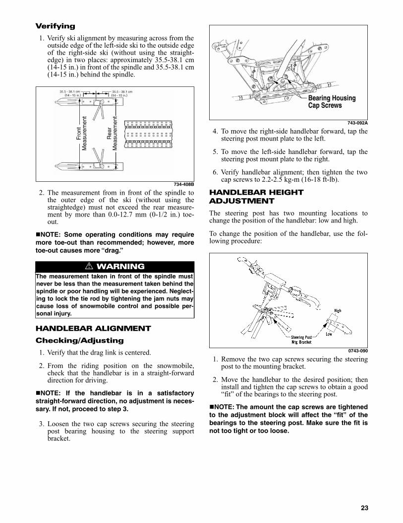
Verifying
1. Verify ski alignment by measuring across from theoutside edge of the left-side ski to the outside edgeof the right-side ski (without using the straight-edge) in two places: approximately 35.5-38.1 cm(14-15 in.) in front of the spindle and 35.5-38.1 cm(14-15 in.) behind the spindle.
734-408B
2. The measurement from in front of the spindle tothe outer edge of the ski (without using thestraightedge) must not exceed the rear measure-ment by more than 0.0-12.7 mm (0-1/2 in.) toe-out.
NOTE: Some operating conditions may requiremore toe-out than recommended; however, moretoe-out causes more “drag.”
HANDLEBAR ALIGNMENT
Checking/Adjusting
1. Verify that the drag link is centered.
2. From the riding position on the snowmobile,check that the handlebar is in a straight-forwarddirection for driving.
NOTE: If the handlebar is in a satisfactorystraight-forward direction, no adjustment is neces-sary. If not, proceed to step 3.
3. Loosen the two cap screws securing the steeringpost bearing housing to the steering supportbracket.
743-092A
4. To move the right-side handlebar forward, tap thesteering post mount plate to the left.
5. To move the left-side handlebar forward, tap thesteering post mount plate to the right.
6. Verify handlebar alignment; then tighten the twocap screws to 2.2-2.5 kg-m (16-18 ft-lb).
HANDLEBAR HEIGHT ADJUSTMENT
The steering post has two mounting locations tochange the position of the handlebar: low and high.
To change the position of the handlebar, use the fol-lowing procedure:
0743-090
1. Remove the two cap screws securing the steeringpost to the mounting bracket.
2. Move the handlebar to the desired position; theninstall and tighten the cap screws to obtain a good“fit” of the bearings to the steering post.
NOTE: The amount the cap screws are tightenedto the adjustment block will affect the “fit” of thebearings to the steering post. Make sure the fit isnot too tight or too loose.
! WARNINGThe measurement taken in front of the spindle mustnever be less than the measurement taken behind thespindle or poor handling will be experienced. Neglect-ing to lock the tie rod by tightening the jam nuts maycause loss of snowmobile control and possible per-sonal injury.
23
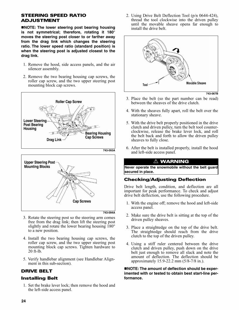
STEERING SPEED RATIO ADJUSTMENT
NOTE: The lower steering post bearing housingis not symmetrical; therefore, rotating it 180°moves the steering post closer to or farther awayfrom the drag link which changes the steeringratio. The lower speed ratio (standard position) iswhen the steering post is adjusted closest to thedrag link.
1. Remove the hood, side access panels, and the airsilencer assembly.
2. Remove the two bearing housing cap screws, theroller cap screw, and the two upper steering postmounting block cap screws.
743-093A
743-094A
3. Rotate the steering post so the steering arm comesfree from the drag link; then lift the steering postslightly and rotate the lower bearing housing 180°to a new position.
4. Install the two bearing housing cap screws, theroller cap screw, and the two upper steering postmounting block cap screws. Tighten hardware to20 ft-lb.
5. Verify handlebar alignment (see Handlebar Align-ment in this sub-section).
DRIVE BELT
Installing Belt
1. Set the brake lever lock; then remove the hood andthe left-side access panel.
2. Using Drive Belt Deflection Tool (p/n 0644-424),thread the tool clockwise into the driven pulleyuntil the movable sheave opens far enough toinstall the drive belt.
743-067B
3. Place the belt (so the part number can be read)between the sheaves of the drive clutch.
4. With the sheaves fully apart, roll the belt over thestationary sheave.
5. With the drive belt properly positioned in the driveclutch and driven pulley, turn the belt tool counter-clockwise, release the brake lever lock, and rollthe belt back and forth to allow the driven pulleysheaves to fully close.
6. After the belt is installed properly, install the hoodand left-side access panel.
Checking/Adjusting Deflection
Drive belt length, condition, and deflection are allimportant for peak performance. To check and adjustdrive belt deflection, use the following procedure.
1. With the engine off; remove the hood and left-sideaccess panel.
2. Make sure the drive belt is sitting at the top of thedriven pulley sheaves.
3. Place a straightedge on the top of the drive belt.The straightedge should reach from the driveclutch to the top of the driven pulley.
4. Using a stiff ruler centered between the driveclutch and driven pulley, push down on the drivebelt just enough to remove all slack and note theamount of deflection. The deflection should beapproximately 15.9-22.2 mm (5/8-7/8 in.).
NOTE: The amount of deflection should be exper-imented with or tested to obtain best start-line per-formance.
! WARNINGNever operate the snowmobile without the belt guardsecured in place.
24

NOTE: Push down on the belt with the ruler onlyuntil the bottom of the belt flexes upward; thenread the amount of deflection.
5. To correct drive belt deflection, loosen the jam nuton the belt width adjuster on the stationary sheave.
6. Using an Allen wrench, adjust the set screw asneeded.
NOTE: Turning the set screw clockwise increasesdistance between the sheaves (increases beltdeflection measurement); turning the set screwcounterclockwise decreases distance between thesheaves (decreases belt deflection measurement).
HYDRAULIC BRAKE SYSTEM
Checking Brake Fluid
1. With the brake fluid reservoir in a level position,check the fluid level. The brake fluid level must bejust below the high mark.
2. If the brake fluid level is below the low mark,remove the reservoir cover and add Arctic Catapproved brake fluid until the fluid level is justbelow the high mark. Install and secure the reser-voir cover. Do not allow moisture to contaminatethe brake system.
Checking Brake Lever Operation
1. Test the operation of the hydraulic brake systemby compressing the brake lever.
2. The brake lever must feel firm when compressed.
RECOMMENDED GASOLINE
The recommended gasoline to use is 87 octane regularunleaded. In many areas, oxygenates (either ethanol orMTBE) are added to the gasoline. Oxygenated gaso-lines containing up to 10% ethanol or up to 15%MTBE are acceptable gasolines.
When using ethanol blended gasoline, it is not neces-sary to add a gasoline antifreeze since ethanol will pre-vent the accumulation of moisture in the fuel system.
NOTE: For optimum performance, do not exceedthe recommended 87 octane gasoline. Using ahigher octane gasoline will not increase overallperformance.
CHECKING HEADLIGHT AIM
1. Position the snowmobile on a level floor so theheadlight is approximately 8 m (25 ft) from anaiming surface (wall or similar surface).
NOTE: There should be an “average” operatingload on the snowmobile when adjusting headlightaim.
2. Measure the distance from the floor to midpoint ofthe headlight.
3. Using the measurement obtained in step 2, make ahorizontal mark on the aiming surface.
4. Make a vertical mark which intersects the horizon-tal mark on the aiming surface directly in front ofthe headlight.
5. Engage the brake lever lock and start the engine.Move the headlight dimmer switch to the HIGHbeam position. DO NOT USE LOW BEAM.
6. Observe the headlight beam aim. Proper aim iswhen the most intense beam is centered on the ver-tical mark 5 cm (2 in.) below the horizontal markon the aiming surface.
0743-091
7. Adjust the headlight adjustment knobs until cor-rect aim is obtained. Shut the engine off; then dis-engage the brake lever lock.
PREOPERATION CHECKS
1. Visually check all fluid levels. Add fluids as nec-essary.
2. Check all switches (tether, dimmer, brakelight,emergency stop) to make sure all function prop-erly.
CAUTIONBrake fluid is highly corrosive. Do not spill brake fluidon any surface of the snowmobile.
! WARNINGDo not overfill the brake fluid reservoir. Overfilling thereservoir may cause the brake system to hydraulicallylock. Use only Arctic Cat approved brake fluid.
CAUTIONUse a 100:1 premix fuel in the gas tank during break-inor engine damage may occur.
CAUTIONDo not use white gas or gasolines containing metha-nol. Only Arctic Cat approved gasoline additivesshould be used.
25

3. Visually check the entire snowmobile for anyloose fasteners. Tighten as required.
4. Test the operation of the brakes. The brake levermust feel firm when the lever is compressed.Inspect the brake fluid level. The brake fluid levelmust be just below the high mark on the brakefluid reservoir. Add Arctic Cat approved brakefluid as necessary.
5. Visually check the headlight, taillight, and brakelight for proper illumination.
TEST RIDE
Test ride the snowmobile 5 to 10 minutes. During andafter the test ride, do the following:
1. Burnish the brake pads by driving the snowmobileslowly and compressing the brake lever repeatedlyuntil the pads just start to heat up; then allow themto cool down. This process stabilizes the pad mate-rial and extends the life of the pads.
2. Allow the engine to cool; then visually check cool-ant level. Add coolant as necessary.
3. Check track alignment and tension.
4. Check the engine compartment and underneath thesnowmobile for any signs of fluid leaks (gas, cool-ant).
General Information
SNOWMOBILE IDENTIFICATION
The Arctic Cat Snowmobile has two important identi-fication numbers. The Vehicle Identification Number(VIN) is stamped on the top of the tunnel. The EngineSerial Number (ESN) is stamped into the crankcase ofthe engine.
0744-098
These numbers are required by the dealer to completewarranty claims properly. No warranty will be allowedby Arctic Cat Inc. if the engine serial number or VIN isremoved or mutilated in any way.
Always provide the snowmobile name, VIN, and ESNwhen contacting an authorized Arctic Cat Snowmobiledealer for parts, service, accessories, or warranty. Ifthe complete engine must be replaced, ask the dealer tonotify Arctic Cat for correct registration information.
For convenience and future reference, record the VINand ESN here.
VIN _______________________________________
ESN _______________________________________
CONTROL LOCATIONS
0744-861
ENGINE BREAK-IN
The engine (when new or rebuilt) requires a shortbreak-in period before the engine is subjected to heavyload conditions.
During the break-in period, a maximum of 1/2 throttleis recommended; however, brief full-throttle accelera-tions and variations in driving speeds contribute togood engine break-in.
SPEEDOMETER/TACHOMETER
This model is equipped with a standard gauge combinationspeedometer/tachometer. Indicator icons are incorporatedwithin the speedometer/tachometer. Also incorporated intothe speedometer/tachometer is a digital readout screen.
FZ003C
A. Oil Pressure/Low Oil
B. Coolant Temperature
C. Low Fuel
D. Fuel Level
E. Service
F. High Beam
G. Not Applicable
26

DIAGNOSTIC CODES
NOTE: If the coolant temperature is at or above80° C (176° F), the icon will flash a warning (alert).If the coolant temperature is at or above 93° C(200° F), the icon will cease flashing and willremain constantly illuminated.
NOTE: At this point, the operator should takeprecautionary measures such as changing toloose snow terrain and/or checking coolant level.
HANDLEBAR TILT
The handlebar can be adjusted to the operator’s prefer-ence. To adjust the handlebar, use the following proce-dure:
1. Loosen the eight cap screws securing the handlebarcaps to the riser and the riser to the steering post.
735-501A
2. Adjust the handlebar up or down to operator’sdesired tilt, tighten the cap screws evenly to 30 ft-lb, and check steering for maximum right/left turn-ing capabilities.
NOTE: Do not adjust the handlebar to a positionthat allows the brake fluid to be below the lowmark on either side of the master cylinder.
REAR BUMPER
The rear bumper can be removed and replaced.
To remove/install a rear bumper, use the followingprocedure.
1. On the inside of the tunnel, drill out the 14 rivetssecuring the rear bumper to both sides of the tunnel.
0744-856
2. Remove the existing bumper and install the newone aligning the holes with the holes in the brack-ets; then rivet the rear bumper to both sides of thetunnel.
EXHAUST SYSTEM
The exhaust system is designed to reduce noise and toimprove the total performance of the engine. If anyexhaust system component is removed from the engineand the engine is run, severe engine damage willresult.
AIR-INTAKE SILENCER
Used in conjunction with the throttle bodies is a spe-cially designed air-intake silencer. The purpose of thesilencer is to quiet the intake of fresh air. Since thethrottle bodies are calibrated with the air-intakesilencer in place, the engine must never be run with thesilencer removed. Performance will not be improved ifthe air-intake silencer is removed. In contrast, severeengine damage will occur.
LIQUID COOLING SYSTEM
The cooling system should be inspected daily for leak-age and damage. Also, the coolant level should bechecked daily. If leakage or damage is detected and theoperator does not feel qualified to service the coolingsystem, see an authorized Arctic Cat Snowmobiledealer for this service.
Code Trouble2 Failure in injector(s).
4 Open or short circuit in barometric pressure sensor.
5 Open or short circuit in intake air temperature sensor.
6 Open or short circuit in water temperature sensor.
7 Open or short circuit in throttle position sensor.
12 Failure in ignition coils.
! WARNINGTighten cap screws according to specifications to pre-vent unexpected “fold-down” of the handlebar duringoperation over rough terrain. DO NOT offset the han-dlebar so steering capabilities are altered or throttleand brake controls will be affected.
CAUTIONThis snowmobile is not designed to be operated industy conditions. Operating the snowmobile in dustyconditions will result in severe engine damage.
27

When filling the cooling system, use a coolant/watermixture which will satisfy the coldest anticipatedweather conditions of your area in accordance with thecoolant manufacturer’s recommendations. While thecooling system is being filled, air pockets maydevelop; therefore, fill the bottle and run the engine forfive to ten minutes after the initial fill (until the ther-mostat opens); then add more coolant if necessary. Fillthe coolant tank and take the snowmobile for a testride. Let the engine cool down; then recheck the cool-ant level and add if necessary.
NOTE: Use a good quality, glycol-based, automo-tive-type antifreeze.
DRIVE BELT
For maximum drive belt life, allow the belt to break inbefore subjecting it to hard use such as wide-open-throttle operation or hill climbing.
If this procedure isn’t followed, a new drive belt canbe destroyed in less than 50 miles.
To increase the life of a drive belt, the belt must bewarmed up before subjecting it to any type of use. Incold temperature (0° or below), the engine should beallowed to idle for a period of 8 to 10 minutes allowingheat from the engine compartment to soften the drivebelt. Not only will this procedure increase belt life butwill also help prevent engine damage from cold sei-zure.
Each operator should be instructed to drive the snow-mobile for several minutes at a low throttle setting towarm the belt up before using wide-open-throttle.
DRIVE CLUTCH AND DRIVEN PULLEY
The drive clutch and driven pulley do not requirelubrication; therefore, no special maintenance isrequired by the snowmobile owner. However, the driveclutch and driven pulley should be disassembled,cleaned, and inspected before each race.
When operating the snowmobile at high altitudes, itmay be necessary to change certain component partsof the drive clutch. If the operator does not feel quali-fied to change clutch components, see an authorizedArctic Cat Snowmobile dealer for this service.
DRIVE CLUTCH/DRIVEN PULLEY ALIGNMENT
The parallelism and the offset between the drive clutchand driven pulley are set at the factory. Normally, noadjustment is necessary as long as neither the driveclutch nor the driven pulley is removed or disassem-bled. However, if premature drive belt wear is experi-enced or if the drive belt turns over, the drive clutch/driven pulley alignment must be checked. If the opera-tor does not feel qualified to align the clutch/pulley,see an authorized Arctic Cat Snowmobile dealer forthis service.
DRIVE CHAIN TENSION
NOTE: The chain tension system is equippedwith a reversible wear pad that can be turned overwhen worn on the first side.
The drive chain must be properly tensioned for properoperation to prevent “ratcheting” and unnecessarychain/sprocket wear. After the first 5 miles (and beforeevery race), the chain tensioner should be adjusted.Arctic Cat recommends that the chain, sprockets, andchain tensioner be checked for wear and proper align-ment and adjustment after every race, every 100 miles,or whenever a drive chain related problem is sus-pected. If the operator does not feel qualified to servicethe drive chain, see an authorized Arctic Cat Snowmo-bile dealer for this service. To adjust the drive chaintensioner, use the following procedure:
1. Loosen the jam nut on the chain tensioner adjust-ment bolt.
2. Tighten the adjustment bolt finger-tight.
0744-070
NOTE: If the adjustment bolt will not turn usingthe fingers (because of dirty threads), use awrench to loosen the bolt; then using the fingers,adjust the bolt until it is finger-tight. Once theadjustment bolt becomes difficult to turn by hand,the drive chain is properly tensioned.
CAUTIONAfter operating the snowmobile for the initial 5-10 min-utes, stop the engine, allow the engine to cool down,and check the coolant level. Add coolant as neces-sary.
! WARNINGWhen following this procedure, the operator must notleave the snowmobile unattended during the warm-upperiod.
CAUTIONUse Clutch Puller (p/n 0744-062). Never substitute adifferent puller or drive clutch damage will occur.
28

3. Lock the adjustment by bottoming the jam nutagainst the chain case.
EFI SYSTEM
Introduction
The EFI system is lightweight in design and is madeup of a number of components explained in this sub-section. The EFI system eliminates the worry ofchanging main jets to compensate for altitude or tem-perature. This EFI system will provide quick and easystarting under all conditions.
The Arctic Cat EFI System operates off a series ofcoils located on the stator and is made up of the fol-lowing components.
1. Charge coils (1 and 2), located on the stator, pro-vide AC voltage to the ECU where AC voltage isconverted to DC voltage.
2. A fuel pump coil located on the stator operates thelow voltage, high output fuel pump. At crankingspeed, the high output fuel pump provides enoughfuel to charge the fuel rail.
3. An injector coil located on the stator provides theinjectors with DC voltage for operation throughthe ECU.
4. A lighting coil located on the stator plate providesoutput to the voltage regulator to operate accesso-ries and the lighting system.
5. An electrical control unit (ECU) calculates inputfrom sensors (air temperature sensor, coolant tem-perature sensor, throttle position sensor, ignitiontiming sensor, barometric pressure sensor) to pro-vide the engine with the correct fuel mixture andtiming for optimum operation.
EFI Features
1. Automatic compensation for temperature.
2. Automatic compensation for altitude.
3. Optimum throttle response through high pressureinjection.
4. Quick starting in every condition.
5. Improved fuel efficiency with maximum mileagein every condition.
6. Engine RPM more stable in every condition.
Precautions
729-325A
Flooded Engine
If the engine should become flooded, set the brakelever lock, compress the throttle lever to the full-openposition, and crank the engine over until it starts andclears itself. Release the brake lever lock.
Fuel System
The EFI fuel system consists of the following compo-nents.
1. Gas tank
2. Electric high output fuel pump
3. Three pick-up valves with micron screens
4. High-pressure fuel hose
5. Fuel rail
6. Fuel pressure regulator
7. Throttle body assembly
8. Fuel injectors
9. ECU
These components are grouped into the fuel handlingsystem. They work together along with electrical sen-sors (following list) and the ECU to provide the enginewith a precise fuel mixture for combustion.
1. Ignition Timing Sensor
! WARNINGWhenever working on the fuel system if a fuel hose isremoved from any component, slowly bleed the pres-sure from the hose into an absorbent towel beforeremoving the hose from the component.
! WARNINGAlways tighten fuel hose clamps securely.
CAUTIONAlways use resistor-type spark plugs and spark plugcaps. Non-resistor components will cause the ECU tomalfunction.
29
2. Air Temperature Sensor
3. Coolant Temperature Sensor
4. Throttle Position Sensor
5. Barometric Pressure Sensor
The fuel is first drawn into the electric fuel pumpthrough two pick-up valves and hoses. The fuel is thenrouted through a high-pressure fuel hose to the fuelrail.
The fuel pressure is maintained in the fuel rail by thefuel regulator. With the fuel pressure maintained at aconstant psi, the ECU evaluates the information itreceives from the electrical sensors and opens theinjectors for precise periods of time (pulse widths) tomeet engine demands.
NOTE: The entire EFI system depends on all coilsfunctioning properly on the stator.
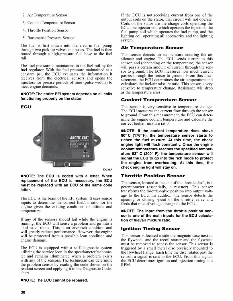
ECU
IO038A
NOTE: The ECU is coded with a letter. Whenreplacement of the ECU is necessary, the ECUmust be replaced with an ECU of the same codeletter.
The ECU is the brain of the EFI system. It uses sensorinputs to determine the correct fuel/air ratio for theengine given the existing conditions of altitude andtemperature.
If any of the sensors should fail while the engine isrunning, the ECU will sense a problem and go into a“fail safe” mode. This is an over-rich condition andwill greatly reduce performance. However, the enginewill be protected from a possible lean condition andengine damage.
The ECU is equipped with a self-diagnostic systemutilizing the service icon in the speedometer/tachome-ter and remains illuminated when a problem existswith any of the sensors. The technician can determinethe problem sensor by reading the code shown on thereadout screen and applying it to the Diagnostic Codeschart.
NOTE: The ECU cannot be repaired.
If the ECU is not receiving current from one of theoutput coils on the stator, that circuit will not operate.Coils on the stator are the charge coils operating theECU, the injector coil which operates the injectors, thefuel pump coil which operates the fuel pump, and thelighting coil operating all accessories and the lightingsystem.
Air Temperature Sensor
This sensor detects air temperature entering the airsilencer and engine. The ECU sends current to thissensor, and (depending on the temperature) the sensorwill pass a certain amount of current through the sen-sor to ground. The ECU measures how much currentpasses through the sensor to ground. From this mea-surement, the ECU determines the air temperature andcalculates the fuel/air mixture ratio. This sensor is verysensitive to temperature change. Resistance will dropas the temperature rises.
Coolant Temperature Sensor
This sensor is very sensitive to temperature change.The ECU measures the current flow through the sensorto ground. From this measurement, the ECU can deter-mine the engine coolant temperature and calculate thecorrect fuel/air mixture ratio.
NOTE: If the coolant temperature rises above80° C (176° F), the temperature sensor starts torichen the fuel mixture. At this time, the checkengine light will flash constantly. Once the enginecoolant temperature reaches the specified temper-ature 93° C (200° F), the temperature sensor willsignal the ECU to go into the rich mode to protectthe engine from overheating. At this time, thecheck engine light will stay on.
Throttle Position Sensor
This sensor, located at the end of the throttle shaft, is apotentiometer (essentially, a resistor). This sensortransforms the throttle-valve position into output volt-age to the ECU. In addition, the sensor detects theopening or closing speed of the throttle valve andfeeds that rate of voltage change to the ECU.
NOTE: The input from the throttle position sen-sor is one of the main inputs for the ECU calcula-tion of fuel/air mixture ratio.
Ignition Timing Sensor
This sensor is located inside the magneto case next tothe flywheel, and the recoil starter and the flywheelmust be removed to access the sensor. This sensor istriggered by a small metal disc precisely mounted tothe flywheel flange. Each time the disc rotates past thesensor, a signal is sent to the ECU. From this signal,the ECU determines ignition and injection timing andRPM.
30

Barometric Pressure Sensor
This sensor is located inside the ECU and is part of theECU unit. Its purpose is to sense atmospheric pressure.From this information, the ECU determines the correctfuel/air mixture ratio.
NOTE: This sensor is not replaceable. If it shouldfail, the ECU must be replaced.
Fuel Injectors
The fuel injectors are positioned in the top of eachthrottle body.
A fuel injector is an electromagnetic injection valvecontrolled by a signal from the ECU. The coil used inthe injector is a high-pressure resistance type. TheECU determines the optimum fuel injection time andduration based on signals from the five sensors.
When voltage is sent to the fuel injector, it energizesthe coil and opens the needle valve, thereby injectingfuel. Because the fuel pressure (pressure differentialbetween fuel line and manifold) is kept constant, theamount of fuel injected is determined by the durationof time the valve is open.
The injectors are coded with letters (A-B-C). Whenreplacement of a fuel injector is necessary, the injectormust be replaced with an injector of the same code let-ter.
IO031A
Fuel Pressure Regulator
The fuel pressure regulator is located in the fuel pumpassembly. The fuel pressure regulator maintains thefuel pressure at a constant specified level.
Fuel Pump Circuit
The fuel pump and its circuit are provided with currentfrom the fuel pump coil on the stator.
For this circuit to function correctly, five componentsmust be properly functioning. Check the followingcomponents before considering the fuel pump assem-bly to be defective.
A. Fuel pump coil - test coil.
B. Emergency stop switch and ignition switchmust be ON.
C. Fuel pump - test fuel pump.
D. Wiring harness and connectors - clean the con-nectors and test the harness.
E. ECU.
SHOCK ABSORBERS
Each shock absorber should be visibly checked daily forexcessive fluid leakage, cracks or breaks in the lowercase, a bent plunger, and wear or leakage in the hoses. Ifany one of these conditions is detected, replacement isnecessary. If the operator does not feel qualified to ser-vice or replace shock absorbers, see an authorized Arc-tic Cat Snowmobile dealer for this service.
TRACK STUDS
NOTE: The track on this snowmobile is notequipped with studs. For additional information,see the 2011 POGA Reference Guide (p/n 5214-070).
The decision to install studs should be made only afterreviewing the International Snowmobile Racing, Inc.regulations as they pertain to the type of racing youparticipate in. Arctic Cat has a variety of studdingproducts available from your authorized Arctic CatSnowmobile dealer.
TOWING
If this snowmobile is to be towed by another snowmo-bile, do not tow using the loops in the skis. The towrope should be attached to the spindles.
Operating Instructions
STARTING AND STOPPING ENGINE
It is imperative that the hydraulic brake system bechecked for wear and proper operation and that allsafety checks found in the accompanying SnowmobileSafety Handbook be performed before attempting tostart the engine. After the engine has been started,check the headlights (high and low beam), taillight,and brakelight to be sure they are working properlyand adjusted correctly. Make sure all lights are clean toprovide maximum illumination. The headlight andtaillight must be clean and must be illuminated when-ever the engine is running.
1. Test the operation of the hydraulic brake systemby compressing the brake lever. The brake levermust feel firm when compressed; then while hold-ing the brake lever in the compressed position,measure the distance between the brake lever andthe handlebar. The distance must be greater than2.54 cm (1 in.).
CAUTIONDo not replace an injector with one of a different letter.Severe engine damage may occur.
31

740-159B
2. Check the brake fluid level in the master cylinderreservoir. The brake fluid level must be just belowthe high mark on the master cylinder reservoir.Add Arctic Cat approved brake fluid as necessary.
740-159A
3. Test the throttle control lever by completely com-pressing and releasing it several times. The leverMUST return to the idle position quickly and com-pletely.
4. Move the emergency stop switch to the RUN posi-tion.
5. Assure that the tether switch cap is secured to thetether switch.
6. Pull the recoil handle slowly until resistance isfelt; then give a short quick pull. Repeat until theengine starts.
7. When the engine starts, allow it to warm up properly.Idle the engine several minutes until the engine hasreached normal operating temperature. Do not idle theengine for excessively long periods of time.
8. Flooding — If the engine does not start but seemsready to start, engage the brake lever lock; then com-press the throttle control lever fully and try to start theengine. When the engine starts, release the throttle con-trol lever immediately. After the warm-up, release thebrake lever lock.
NOTE: If the engine fails to start during theattempt with the throttle control lever compressed,remove the spark plugs and clean and dry themthoroughly or install a new set of properly gapped,recommended spark plugs.
9. To shut off the engine, either depress the emer-gency stop switch to the OFF position or pull thetether switch cap off the tether switch.
BRAKING
Operating a snowmobile with hydraulic brakes is dif-ferent from operating a snowmobile with mechanicalbrakes. The following items are items that the operatormust be familiar with when operating this snowmobileand its hydraulic brake system.
NOTE: Important additional information on theproper maintenance of the brake system is foundin the maintenance section of this manual.
! WARNINGDo not start the engine if the brake system is not func-tioning properly (if the lever feels spongy, if the brakelever can be compressed to within 2.54 cm (1 in.) ofthe handlebar, or if the brake fluid level is not correct).Service the brake system or have it properly repairedprior to operating the snowmobile. Serious personalinjury or even death may occur if the brake system isnot operating properly.
CAUTIONAlways check the coolant level before starting theengine.
CAUTIONTo avoid damaging the recoil starter, DO NOT pull therecoil rope to its limit or release the recoil handle froman extended position. Allow the rope to rewind slowly.
CAUTIONIt is extremely important that the engine is properlywarmed up before subjecting the engine to high speedoperation or heavy loads. Do not idle the engine forexcessively long periods of time. The engine shouldbe allowed to idle at least 1-2 minutes before it is oper-ated at more than 1/2 throttle. In extremely cold condi-tions, the warm-up time will be longer. Cold seizureand piston scuffing caused by insufficient warm-upwill not be covered by warranty. Also, do not idle theengine for excessively long periods of time.
32

1. Use the brakes wisely. Each time the brakes areapplied in all hydraulic brake systems (includingautomotive applications), heat is transferred to thebrake fluid. The amount of heat transferred duringhigh speed stops and/or repetitive use may be highenough to boil the brake fluid and cause the brakesto either fade or may cause an unexpected loss ofbrakes. If this occurs, the brake fluid requires acool down period before the brakes will againfunction properly. This cool down period will varydepending upon the ambient air temperature andthe temperature of the brake fluid. If loss of brakeshas occurred because of high fluid temperatures,do not operate the snowmobile until the cool downperiod has expired and brake lever firmness hasreturned.
2. Be sure to maintain the brake fluid at the properlevel and take care not to get any moisture in thesystem as moisture in the brake fluid lowers theboiling point. If the brake fluid is ever boiled (byhigh speed stops or repetitive use) or if moisture isallowed to enter the system, it must be changed.Never substitute or mix different types or gradesof brake fluid.
3. Never ride the brake. Even maintaining minimalpressure on the brake lever will cause the brakepads to drag on the disc and may overheat thebrake fluid.
4. The brake lever lock is not a parking brake andshould not be applied for periods exceeding 5 min-utes. NEVER OPERATE THE SNOWMOBILEWITH THE BRAKE LEVER LOCK ENGAGED.
5. Pumping the brake lever is permissible but notacceptable on a snowmobile designed for racing;therefore, if pumping the brake lever more thantwice is necessary to obtain the necessary stoppingpower, the system must be serviced. If the operatordoes not feel qualified to service the brake system,see an authorized Arctic Cat Snowmobile dealerfor this service.
6. When new brake pads are installed, a “burnishing”process is required. Drive the snowmobile slowlyand compress the brake lever several times untilthe pads just start to heat up; then allow them tothoroughly cool down. This process stabilizes thepad material and extends the life of the pads.
EMERGENCY STOPPING
There are several methods of stopping or slowing thesnowmobile under a variety of situations. Identified inthe following chart are the ways a snowmobile may bebrought to a stop and the effectiveness under normalconditions.
Lubrication
CHAIN CASE
The recommended amount of transmission lube in thechain case is 236 ml (8 fl oz). Adding more transmis-sion lube to the chain case (above the recommendedamount) may result in leakage. To check the transmis-sion lube level, use the following procedure:
1. With the snowmobile level, shut engine off andwait for all moving parts to stop; then open thehood.
2. Remove the oil level stick from the chain case.Wipe the oil level stick clean; then install the oillevel stick completely back into the chain case.Remove the oil level stick again and check thelubricant level.
! WARNINGExcessive repetitive use of the hydraulic brake forhigh speed stops will cause overheating of the brakefluid and premature brake pad wear which will resultin an unexpected loss of brakes.
! WARNINGUse only Arctic Cat approved brake fluid. Never sub-stitute or mix different types or grades of brake fluid.Brake loss can result. Check brake fluid level and padwear before each use. Brake loss can result in severeinjury or even death.
! WARNINGThe brake lever lock is not a parking brake and shouldnot be applied for periods exceeding 5 minutes. Thebrake lever lock maintains the brake lever in the com-pressed position and maintains pressure against thebrake disc; however, after a period of time, the pres-sure applied to the brake disc may relax below theamount required to hold the snowmobile stationary.
ITEM FUNCTION CONDITIONEmergency Stop Switch interrupts ignition circuit ALL
Tether Switch interrupts ignition circuit ALL
Brake slows the driveshaft ALL
! WARNINGIf any malfunction of the throttle system occurs (suchas freezing in fluffy snow) and the engine does not idledown, use the emergency stop switch or disconnectthe tether switch IMMEDIATELY to stop the engine. DONOT start the engine until the malfunction in the car-buretor/ throttle system has been located and cor-rected.
! WARNINGIf the throttle control lever does not work properly, DONOT ATTEMPT TO START THE ENGINE.
33

728-948A
3. If the lubricant level is above the add mark, thelubricant level is satisfactory. If the lubricant levelis at or below the add mark, proceed to step 4.
4. If oil is low, add transmission lube through the oillevel stick filler hole. When the oil level is correct,install the oil level stick.
NOTE: If excessive oil deposits are noticed, thechain case must be serviced. Also, when the oillevel is at the add mark, approximately 60 ml (2 floz) of transmission lube must be added to thechain case.
FRONT SUSPENSION
It is very important that the bellcrank is greased on amonthly basis using a good low-temperature grease.The bellcrank should also be greased after traileringthe snowmobile on an open trailer. Pump grease intothe grease fittings and wipe excess grease from thebellcrank.
0744-878
REAR SUSPENSION
1. Shut engine off and wait for all moving parts tostop.
2. With the gas tank nearly empty (less than 1/4 full),lay the snowmobile on its side. A piece of card-board should be used to protect the finish on thehood and belly pan.
NOTE: Prior to tipping the snowmobile on itsside, apply the brake and set the brake lever lock.
3. Remove ice and snow buildup from the skid frameto expose the grease fittings.
0741-175
0744-072
4. Lubricate the grease fittings with an all-tempera-ture grease.
CAUTIONThe correct lubricant to use in the chain case is ArcticCat Transmission Lube (p/n 4639-364). Any substitutemay cause premature chain failure or serious damageto the chain drive system.
34

Maintenance
The longevity and safety of the snowmobile can be increased by making periodic checks of the items in the follow-ing checklist. Perform maintenance checks more often if the snowmobile is used under severe conditions.
R= Replace, T=Tighten, I = Inspect and clean, adjust, or replace if necessary
PERIODIC MAINTENANCE CHECKLIST
INTERVAL EVERYRACE
EVERY3 RACES
EVERY5 RACES
REMARKSSERVICE ITEM HRS EVERY
1 ½ - 2 HRSEVERY
4 ¼ - 6 HRSEVERY
7 ½ - 10 HRSSpark Plugs I R I Check for condition and heat range.
Spark Plug End Caps I I R Check for secure connection.
Drive Belt I I R Check for proper deflection, burn spots/wear.
Cooling System I I I Replace coolant and engine coolant hoses every year.
Chain Case Lubricant I R I Change after break-in period.
Drive Chain/Sprockets I I I Inspect for broken/stretched links.
Chain Tensioner I I I Inspect for worn or damaged components. Check andretighten sprocket cap screws.
Brake Fluid I R I Replace brake hose every year.
Brake Pads I I I Inspect for wear.
Throttle Cable/Lever I I I Inspect for proper adjustment and wear.
Fuel Hoses I I I Inspect for wear and pinching. Replace yearly.
Exhaust System I I I Check for cracks and missing springs.
Pistons/Rings — — R
Reed Valves I Replace yearly.
Front Suspension I I I Apply grease to bellcrank fittings. Inspect for damaged parts.
Steering I I I Inspect ski alignment. Check for damaged or worncomponents. Apply grease to bell crank fittings and steeringbearing.
Rear Suspension I I I Inspect for damaged or worn components. Apply grease tofittings.
Shock Oil — — — Change oil at end of normal race season (10-12 races). If along race season is planned, change oil mid-season and atend of season.
Track I I I Inspect for proper tension/alignment.
Wear Strips I I I Inspect for wear/damage.
Drive Clutch I I I Inspect surfaces for belt build-up and glazing.
Driven Pulley I I I Inspect for glazing.
Recoil Rope/Handle I I I Inspect rope for fraying/handle for cracks.
Skis and Wear Bars I I I Check condition and alignment.
Cap Screws/Nuts T T T Tighten to torque specifications (if applicable).
35
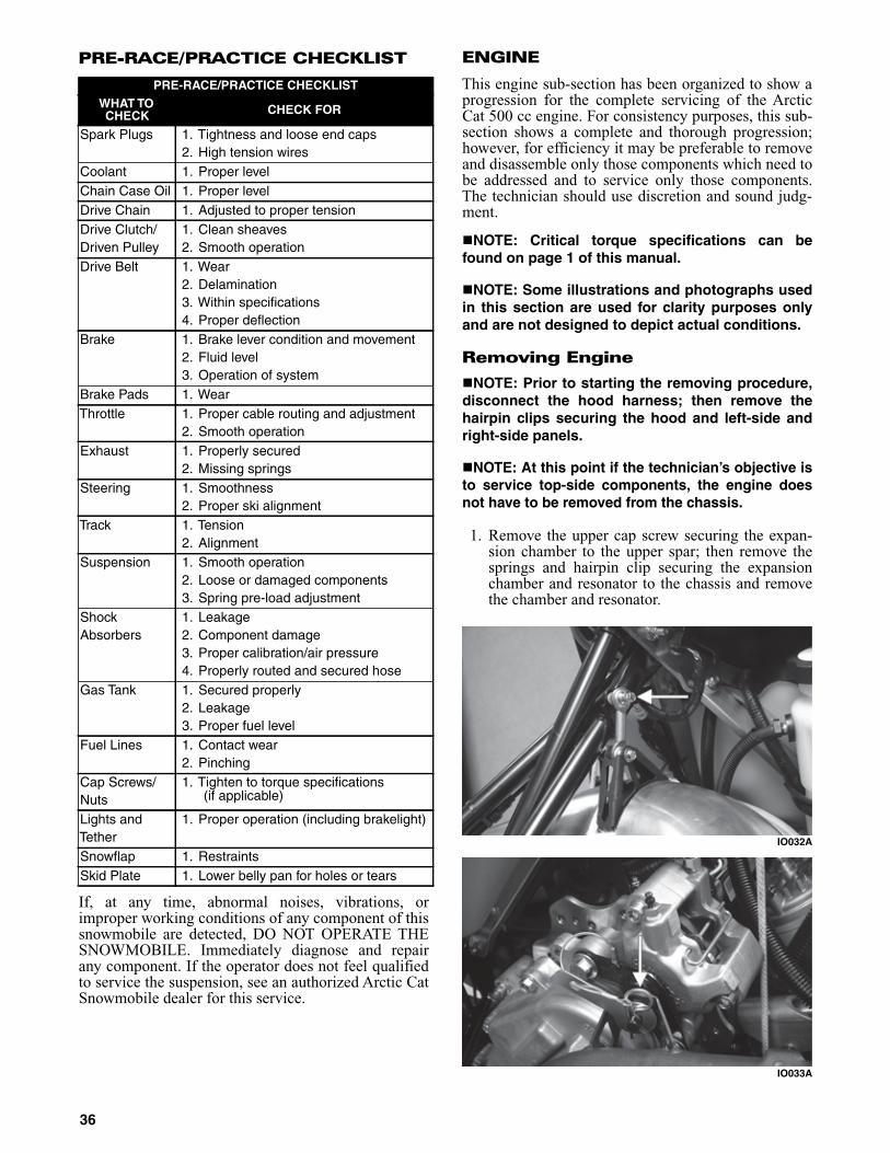
PRE-RACE/PRACTICE CHECKLIST
If, at any time, abnormal noises, vibrations, orimproper working conditions of any component of thissnowmobile are detected, DO NOT OPERATE THESNOWMOBILE. Immediately diagnose and repairany component. If the operator does not feel qualifiedto service the suspension, see an authorized Arctic CatSnowmobile dealer for this service.
ENGINE
This engine sub-section has been organized to show aprogression for the complete servicing of the ArcticCat 500 cc engine. For consistency purposes, this sub-section shows a complete and thorough progression;however, for efficiency it may be preferable to removeand disassemble only those components which need tobe addressed and to service only those components.The technician should use discretion and sound judg-ment.
NOTE: Critical torque specifications can befound on page 1 of this manual.
NOTE: Some illustrations and photographs usedin this section are used for clarity purposes onlyand are not designed to depict actual conditions.
Removing Engine
NOTE: Prior to starting the removing procedure,disconnect the hood harness; then remove thehairpin clips securing the hood and left-side andright-side panels.
NOTE: At this point if the technician’s objective isto service top-side components, the engine doesnot have to be removed from the chassis.
1. Remove the upper cap screw securing the expan-sion chamber to the upper spar; then remove thesprings and hairpin clip securing the expansionchamber and resonator to the chassis and removethe chamber and resonator.
IO032A
IO033A
PRE-RACE/PRACTICE CHECKLISTWHAT TOCHECK CHECK FOR
Spark Plugs 1. Tightness and loose end caps2. High tension wires
Coolant 1. Proper levelChain Case Oil 1. Proper levelDrive Chain 1. Adjusted to proper tensionDrive Clutch/Driven Pulley
1. Clean sheaves2. Smooth operation
Drive Belt 1. Wear2. Delamination3. Within specifications4. Proper deflection
Brake 1. Brake lever condition and movement2. Fluid level3. Operation of system
Brake Pads 1. WearThrottle 1. Proper cable routing and adjustment
2. Smooth operationExhaust 1. Properly secured
2. Missing springsSteering 1. Smoothness
2. Proper ski alignmentTrack 1. Tension
2. AlignmentSuspension 1. Smooth operation
2. Loose or damaged components3. Spring pre-load adjustment
ShockAbsorbers
1. Leakage2. Component damage3. Proper calibration/air pressure4. Properly routed and secured hose
Gas Tank 1. Secured properly2. Leakage3. Proper fuel level
Fuel Lines 1. Contact wear2. Pinching
Cap Screws/Nuts
1. Tighten to torque specifications(if applicable)
Lights andTether
1. Proper operation (including brakelight)
Snowflap 1. RestraintsSkid Plate 1. Lower belly pan for holes or tears
36
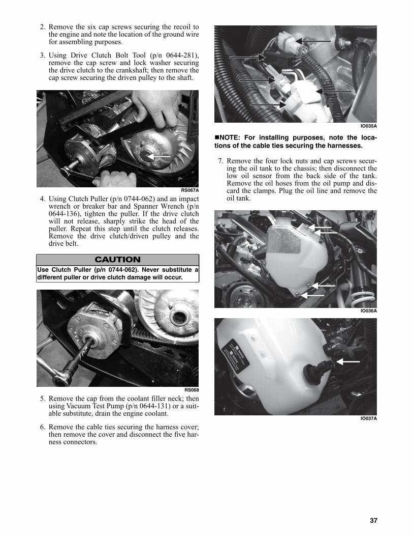
2. Remove the six cap screws securing the recoil tothe engine and note the location of the ground wirefor assembling purposes.
3. Using Drive Clutch Bolt Tool (p/n 0644-281),remove the cap screw and lock washer securingthe drive clutch to the crankshaft; then remove thecap screw securing the driven pulley to the shaft.
RS067A
4. Using Clutch Puller (p/n 0744-062) and an impactwrench or breaker bar and Spanner Wrench (p/n0644-136), tighten the puller. If the drive clutchwill not release, sharply strike the head of thepuller. Repeat this step until the clutch releases.Remove the drive clutch/driven pulley and thedrive belt.
RS068
5. Remove the cap from the coolant filler neck; thenusing Vacuum Test Pump (p/n 0644-131) or a suit-able substitute, drain the engine coolant.
6. Remove the cable ties securing the harness cover;then remove the cover and disconnect the five har-ness connectors.
IO035A
NOTE: For installing purposes, note the loca-tions of the cable ties securing the harnesses.
7. Remove the four lock nuts and cap screws secur-ing the oil tank to the chassis; then disconnect thelow oil sensor from the back side of the tank.Remove the oil hoses from the oil pump and dis-card the clamps. Plug the oil line and remove theoil tank.
IO036A
IO037A
CAUTIONUse Clutch Puller (p/n 0744-062). Never substitute adifferent puller or drive clutch damage will occur.
37
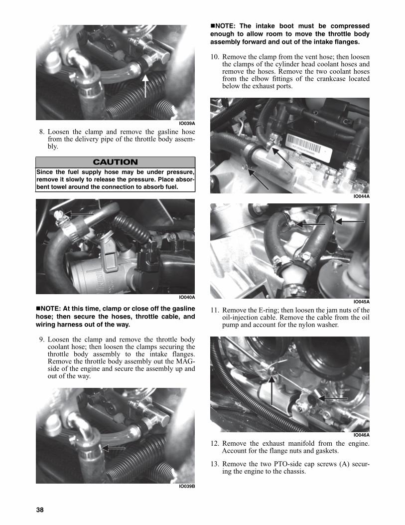
IO039A
8. Loosen the clamp and remove the gasline hosefrom the delivery pipe of the throttle body assem-bly.
IO040A
NOTE: At this time, clamp or close off the gaslinehose; then secure the hoses, throttle cable, andwiring harness out of the way.
9. Loosen the clamp and remove the throttle bodycoolant hose; then loosen the clamps securing thethrottle body assembly to the intake flanges.Remove the throttle body assembly out the MAG-side of the engine and secure the assembly up andout of the way.
IO039B
NOTE: The intake boot must be compressedenough to allow room to move the throttle bodyassembly forward and out of the intake flanges.
10. Remove the clamp from the vent hose; then loosenthe clamps of the cylinder head coolant hoses andremove the hoses. Remove the two coolant hosesfrom the elbow fittings of the crankcase locatedbelow the exhaust ports.
IO044A
IO045A
11. Remove the E-ring; then loosen the jam nuts of theoil-injection cable. Remove the cable from the oilpump and account for the nylon washer.
IO046A
12. Remove the exhaust manifold from the engine.Account for the flange nuts and gaskets.
13. Remove the two PTO-side cap screws (A) secur-ing the engine to the chassis.
CAUTIONSince the fuel supply hose may be under pressure,remove it slowly to release the pressure. Place absor-bent towel around the connection to absorb fuel.
38

0744-860
14. Remove the cap screw (B) securing the upperMAG-side engine mount to the chassis; thenremove the lower cap screw (C) securing theengine to the chassis.
15. Move the engine up far enough to gain access tothe coolant hose clamps securing the hoses to thelower crankcase and thermostat housing; thenloosen the clamps and remove the coolant hoses.
16. Remove the engine from the MAG-side of thechassis and account for the engine mount spacer(A) located between the MAG-side and PTO-sideengine mounting bracket; then with the engineremoved, remove the cap screws securing theengine mounting brackets to the engine.
0744-859
NOTE: For installing purposes, note the locationof the different-length cap screws.
Disassembling Engine
NOTE: It is advisable to loosen the spark plugsprior to disassembling the engine.
1. Using the Flywheel Spanner Wrench (p/n 0144-007) to secure the flywheel, remove the flywheelcap screw and flat washer; then remove the threestarter pulley cap screws and remove the pulley.
FC014
FC015
2. Install Flywheel Puller Insert (p/n 0644-179) ontothe end of the crankshaft.
FC016
3. Using Flywheel Puller (p/n 0744-040) or suitablesubstitute, remove the flywheel from the crank-shaft by tightening the puller bolt, striking thehead of the puller bolt with a hammer, and tighten-ing again. Repeat this procedure until the flywheelis free. Account for the key.
CAUTIONTo prevent damage to the crankshaft, do not threadpuller bolts more than 12.7 mm (1/2 in.) into the fly-wheel. Damage to the coils may result.
39
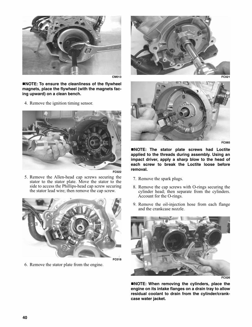
CM013
NOTE: To ensure the cleanliness of the flywheelmagnets, place the flywheel (with the magnets fac-ing upward) on a clean bench.
4. Remove the ignition timing sensor.
FC022
5. Remove the Allen-head cap screws securing thestator to the stator plate. Move the stator to theside to access the Phillips-head cap screw securingthe stator lead wire; then remove the cap screw.
FC018
6. Remove the stator plate from the engine.
FC021
FC065
NOTE: The stator plate screws had Loctiteapplied to the threads during assembly. Using animpact driver, apply a sharp blow to the head ofeach screw to break the Loctite loose beforeremoval.
7. Remove the spark plugs.
8. Remove the cap screws with O-rings securing thecylinder head; then separate from the cylinders.Account for the O-rings.
9. Remove the oil-injection hose from each flangeand the crankcase nozzle.
FC026
NOTE: When removing the cylinders, place theengine on its intake flanges on a drain tray to allowresidual coolant to drain from the cylinder/crank-case water jacket.
40

10. Remove the eight nuts securing the cylinders to thecrankcase; then using a rubber hammer, gently tapthe cylinders and remove from the crankcase bylifting them straight up off their studs. Account forgasket(s) and any alignment pins.
FC067
11. Remove the PTO-side piston-pin circlip from thePTO-side piston; then remove the MAG-side pis-ton-pin circlip from the MAG-side piston.
CM149
12. Using Piston Pin Puller (p/n 0644-328)0, removethe piston pins from both pistons.
NOTE: For proper assembly, keep all MAG-sidecomponents and all PTO-side components sepa-rated. Assemble them on their proper sides.
FC029
13. Lift the pistons clear of the connecting rods andremove the small-end connecting-rod bearings(account for two washers); then remove the pistonrings. Keep each piston with its rings; keep eachpiston pin and bearing together as a set.
AN317D
NOTE: Place rubber bands over the connectingrods and around the cylinder studs to prevent theconnecting rods from damaging the crankcase.
14. Remove the intake flanges and reed valve assem-blies.
FC030
15. Remove the three cap screws securing the thermostatcap; then remove the cap, gasket, and thermostat.
FC032
CAUTIONWhen removing a cylinder, be sure to support the pis-ton to prevent damage to the crankcase and piston.
CAUTIONDO NOT use any type of punch to drive the piston pinfree of the piston; damage may result. Use a piston-pin puller only.
41
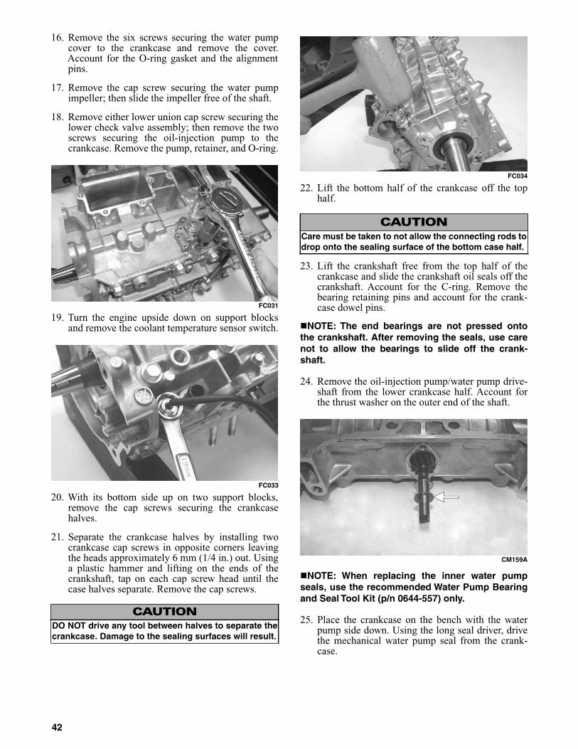
16. Remove the six screws securing the water pumpcover to the crankcase and remove the cover.Account for the O-ring gasket and the alignmentpins.
17. Remove the cap screw securing the water pumpimpeller; then slide the impeller free of the shaft.
18. Remove either lower union cap screw securing thelower check valve assembly; then remove the twoscrews securing the oil-injection pump to thecrankcase. Remove the pump, retainer, and O-ring.
FC031
19. Turn the engine upside down on support blocksand remove the coolant temperature sensor switch.
FC033
20. With its bottom side up on two support blocks,remove the cap screws securing the crankcasehalves.
21. Separate the crankcase halves by installing twocrankcase cap screws in opposite corners leavingthe heads approximately 6 mm (1/4 in.) out. Usinga plastic hammer and lifting on the ends of thecrankshaft, tap on each cap screw head until thecase halves separate. Remove the cap screws.
FC034
22. Lift the bottom half of the crankcase off the tophalf.
23. Lift the crankshaft free from the top half of thecrankcase and slide the crankshaft oil seals off thecrankshaft. Account for the C-ring. Remove thebearing retaining pins and account for the crank-case dowel pins.
NOTE: The end bearings are not pressed ontothe crankshaft. After removing the seals, use carenot to allow the bearings to slide off the crank-shaft.
24. Remove the oil-injection pump/water pump drive-shaft from the lower crankcase half. Account forthe thrust washer on the outer end of the shaft.
CM159A
NOTE: When replacing the inner water pumpseals, use the recommended Water Pump Bearingand Seal Tool Kit (p/n 0644-557) only.
25. Place the crankcase on the bench with the waterpump side down. Using the long seal driver, drivethe mechanical water pump seal from the crank-case.
CAUTIONDO NOT drive any tool between halves to separate thecrankcase. Damage to the sealing surfaces will result.
CAUTIONCare must be taken to not allow the connecting rods todrop onto the sealing surface of the bottom case half.
42

FC036
26. Using a pair of snap ring pliers, remove the snapring securing the inner seal in the crankcase.
27. Using the hooked end of the tool, pull the innerseal free of the crankcase.
28. Using the hooked end of the tool, pry the seal ringfrom the backside of the water pump impeller.
AN327D
Cleaning and Inspecting Engine
NOTE: Whenever a part is worn excessively,cracked, or damaged in any way, replacement isnecessary.
Cylinder Head
1. Using a non-metallic carbon removal tool, removeany carbon buildup from the combustion chambersbeing careful not to nick, scrape, or damage thecombustion chambers or the sealing surfaces.
2. Inspect the spark-plug holes for any damagedthreads.
3. Inspect the cylinder head for flatness using astraightedge and a feeler gauge. Acceptable war-page must not exceed 0.002 in.
NOTE: If the warpage exceeds specification,resurface the cylinder head using proceduresidentified in step 4.
FS270
4. Place the cylinder heads on a Surface Plate (p/n0644-016) covered with #400 grit wet-or-drysandpaper. Using light pressure, move each cylin-der head in a figure eight motion. Inspect the seal-ing surface for any indication of high spots. A highspot can be noted by a bright metallic finish. Cor-rect any high spots before assembly by continuingto move the cylinder head in a figure eight motionuntil a uniform bright metallic finish is attained.
CM018
Cylinders
1. Using a non-metallic carbon removal tool, removecarbon buildup from the exhaust ports.
2. Wash the cylinders in parts-cleaning solvent.
3. Inspect the cylinders for pitting, scoring, scuffing,and corrosion. If marks are found, repair the sur-face with a Ball Hone (p/n 0644-292) and honingoil.
NOTE: To produce the proper 45° crosshatch pat-tern, maintain a low drill RPM. If honing oil is notavailable, use a lightweight, petroleum-based oil.Thoroughly clean the cylinders after honing usingdetergent soap and hot water and dry with com-pressed air; then immediately apply oil to the cyl-inder bores. If a bore is severely damaged orgouged, the cylinder must be replaced.
CAUTIONWater or parts-cleaning solvent must be used in con-junction with the wet-or-dry sandpaper or damage tothe sealing surface may result.
43
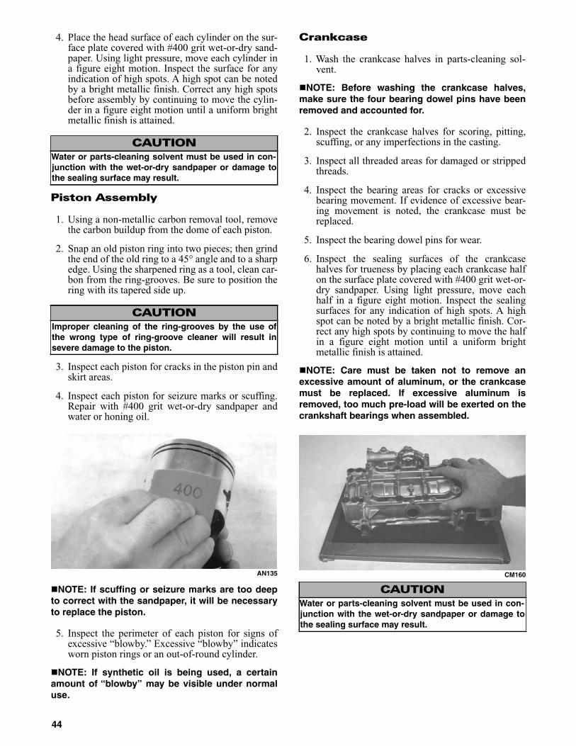
4. Place the head surface of each cylinder on the sur-face plate covered with #400 grit wet-or-dry sand-paper. Using light pressure, move each cylinder ina figure eight motion. Inspect the surface for anyindication of high spots. A high spot can be notedby a bright metallic finish. Correct any high spotsbefore assembly by continuing to move the cylin-der in a figure eight motion until a uniform brightmetallic finish is attained.
Piston Assembly
1. Using a non-metallic carbon removal tool, removethe carbon buildup from the dome of each piston.
2. Snap an old piston ring into two pieces; then grindthe end of the old ring to a 45° angle and to a sharpedge. Using the sharpened ring as a tool, clean car-bon from the ring-grooves. Be sure to position thering with its tapered side up.
3. Inspect each piston for cracks in the piston pin andskirt areas.
4. Inspect each piston for seizure marks or scuffing.Repair with #400 grit wet-or-dry sandpaper andwater or honing oil.
AN135
NOTE: If scuffing or seizure marks are too deepto correct with the sandpaper, it will be necessaryto replace the piston.
5. Inspect the perimeter of each piston for signs ofexcessive “blowby.” Excessive “blowby” indicatesworn piston rings or an out-of-round cylinder.
NOTE: If synthetic oil is being used, a certainamount of “blowby” may be visible under normaluse.
Crankcase
1. Wash the crankcase halves in parts-cleaning sol-vent.
NOTE: Before washing the crankcase halves,make sure the four bearing dowel pins have beenremoved and accounted for.
2. Inspect the crankcase halves for scoring, pitting,scuffing, or any imperfections in the casting.
3. Inspect all threaded areas for damaged or strippedthreads.
4. Inspect the bearing areas for cracks or excessivebearing movement. If evidence of excessive bear-ing movement is noted, the crankcase must bereplaced.
5. Inspect the bearing dowel pins for wear.
6. Inspect the sealing surfaces of the crankcasehalves for trueness by placing each crankcase halfon the surface plate covered with #400 grit wet-or-dry sandpaper. Using light pressure, move eachhalf in a figure eight motion. Inspect the sealingsurfaces for any indication of high spots. A highspot can be noted by a bright metallic finish. Cor-rect any high spots by continuing to move the halfin a figure eight motion until a uniform brightmetallic finish is attained.
NOTE: Care must be taken not to remove anexcessive amount of aluminum, or the crankcasemust be replaced. If excessive aluminum isremoved, too much pre-load will be exerted on thecrankshaft bearings when assembled.
CM160
CAUTIONWater or parts-cleaning solvent must be used in con-junction with the wet-or-dry sandpaper or damage tothe sealing surface may result.
CAUTIONImproper cleaning of the ring-grooves by the use ofthe wrong type of ring-groove cleaner will result insevere damage to the piston.
CAUTIONWater or parts-cleaning solvent must be used in con-junction with the wet-or-dry sandpaper or damage tothe sealing surface may result.
44
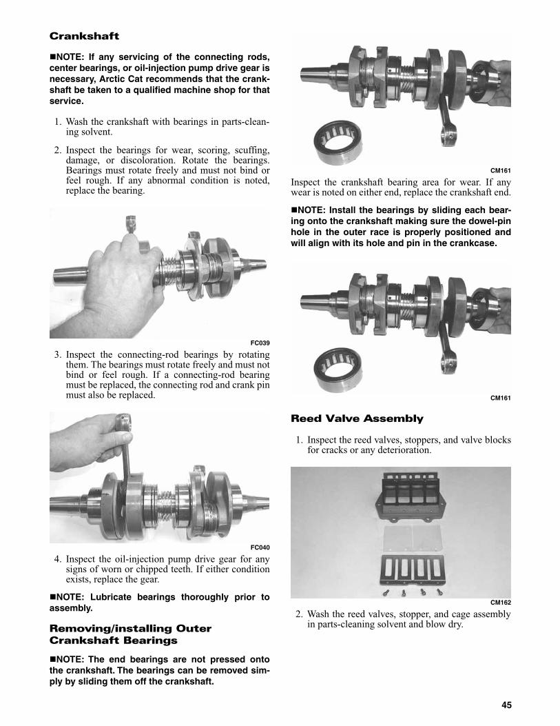
Crankshaft
NOTE: If any servicing of the connecting rods,center bearings, or oil-injection pump drive gear isnecessary, Arctic Cat recommends that the crank-shaft be taken to a qualified machine shop for thatservice.
1. Wash the crankshaft with bearings in parts-clean-ing solvent.
2. Inspect the bearings for wear, scoring, scuffing,damage, or discoloration. Rotate the bearings.Bearings must rotate freely and must not bind orfeel rough. If any abnormal condition is noted,replace the bearing.
FC039
3. Inspect the connecting-rod bearings by rotatingthem. The bearings must rotate freely and must notbind or feel rough. If a connecting-rod bearingmust be replaced, the connecting rod and crank pinmust also be replaced.
FC040
4. Inspect the oil-injection pump drive gear for anysigns of worn or chipped teeth. If either conditionexists, replace the gear.
NOTE: Lubricate bearings thoroughly prior toassembly.
Removing/installing Outer Crankshaft Bearings
NOTE: The end bearings are not pressed ontothe crankshaft. The bearings can be removed sim-ply by sliding them off the crankshaft.
CM161
Inspect the crankshaft bearing area for wear. If anywear is noted on either end, replace the crankshaft end.
NOTE: Install the bearings by sliding each bear-ing onto the crankshaft making sure the dowel-pinhole in the outer race is properly positioned andwill align with its hole and pin in the crankcase.
CM161
Reed Valve Assembly
1. Inspect the reed valves, stoppers, and valve blocksfor cracks or any deterioration.
CM162
2. Wash the reed valves, stopper, and cage assemblyin parts-cleaning solvent and blow dry.
45
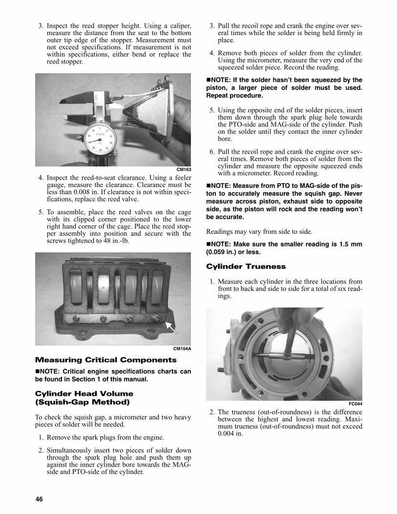
3. Inspect the reed stopper height. Using a caliper,measure the distance from the seat to the bottomouter tip edge of the stopper. Measurement mustnot exceed specifications. If measurement is notwithin specifications, either bend or replace thereed stopper.
CM163
4. Inspect the reed-to-seat clearance. Using a feelergauge, measure the clearance. Clearance must beless than 0.008 in. If clearance is not within speci-fications, replace the reed valve.
5. To assemble, place the reed valves on the cagewith its clipped corner positioned to the lowerright hand corner of the cage. Place the reed stop-per assembly into position and secure with thescrews tightened to 48 in.-lb.
CM164A
Measuring Critical Components
NOTE: Critical engine specifications charts canbe found in Section 1 of this manual.
Cylinder Head Volume (Squish-Gap Method)
To check the squish gap, a micrometer and two heavypieces of solder will be needed.
1. Remove the spark plugs from the engine.
2. Simultaneously insert two pieces of solder downthrough the spark plug hole and push them upagainst the inner cylinder bore towards the MAG-side and PTO-side of the cylinder.
3. Pull the recoil rope and crank the engine over sev-eral times while the solder is being held firmly inplace.
4. Remove both pieces of solder from the cylinder.Using the micrometer, measure the very end of thesqueezed solder piece. Record the reading.
NOTE: If the solder hasn’t been squeezed by thepiston, a larger piece of solder must be used.Repeat procedure.
5. Using the opposite end of the solder pieces, insertthem down through the spark plug hole towardsthe PTO-side and MAG-side of the cylinder. Pushon the solder until they contact the inner cylinderbore.
6. Pull the recoil rope and crank the engine over sev-eral times. Remove both pieces of solder from thecylinder and measure the opposite squeezed endswith a micrometer. Record reading.
NOTE: Measure from PTO to MAG-side of the pis-ton to accurately measure the squish gap. Nevermeasure across piston, exhaust side to oppositeside, as the piston will rock and the reading won’tbe accurate.
Readings may vary from side to side.
NOTE: Make sure the smaller reading is 1.5 mm(0.059 in.) or less.
Cylinder Trueness
1. Measure each cylinder in the three locations fromfront to back and side to side for a total of six read-ings.
FC044
2. The trueness (out-of-roundness) is the differencebetween the highest and lowest reading. Maxi-mum trueness (out-of-roundness) must not exceed0.004 in.
46

0725-586
Piston Skirt/cylinder Clearance
1. Measure each cylinder front to back about 1 in.from the bottom of each cylinder.
2. Measure the corresponding piston skirt diameter ata point 1 cm above the piston skirt at a right angleto the piston-pin bore. Subtract this measurementfrom the measurement in step 1. The difference(clearance) must be within 0.0030-0.0041 in.
AC091
Piston-ring End Gap
1. Place each piston ring in the wear portion above theexhaust port of its respective cylinder. Use the pis-ton to position each ring squarely in each cylinder.
2. Using a feeler gauge, measure each piston-ringend gap. Acceptable ring end gap must be within0.008-0.016 in.
FC045
Piston Pin And Piston-pin Bore
1. Measure the piston pin diameter at each end and inthe center. Acceptable piston pin measurementmust be within 0.8659-0.8661 in. If any measure-ment varies by more than 0.001 in., the piston pinand bearing must be replaced as a set.
IO012
2. Insert a snap gauge into each piston-pin bore; thenremove the gauge and measure it with a microme-ter. The diameter measurement must be within0.8661-0.8665 in. Take two measurements toensure accuracy.
AC092
Connecting-rod Small End Bore
1. Insert a snap gauge into each connecting-rod smallend bore; then remove the gauge and measure itwith a micrometer.
AN061
47
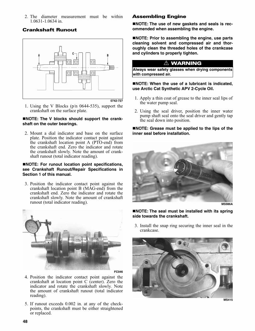
2. The diameter measurement must be within1.0631-1.0634 in.
Crankshaft Runout
0742-727
1. Using the V Blocks (p/n 0644-535), support thecrankshaft on the surface plate.
NOTE: The V blocks should support the crank-shaft on the outer bearings.
2. Mount a dial indicator and base on the surfaceplate. Position the indicator contact point againstthe crankshaft location point A (PTO-end) fromthe crankshaft end. Zero the indicator and rotatethe crankshaft slowly. Note the amount of crank-shaft runout (total indicator reading).
NOTE: For runout location point specifications,see Crankshaft Runout/Repair Specifications inSection 1 of this manual.
3. Position the indicator contact point against thecrankshaft location point B (MAG-end) from thecrankshaft end. Zero the indicator and rotate thecrankshaft slowly. Note the amount of crankshaftrunout (total indicator reading).
FC046
4. Position the indicator contact point against thecrankshaft at location point C (center). Zero theindicator and rotate the crankshaft slowly. Notethe amount of crankshaft runout (total indicatorreading).
5. If runout exceeds 0.002 in. at any of the check-points, the crankshaft must be either straightenedor replaced.
Assembling Engine
NOTE: The use of new gaskets and seals is rec-ommended when assembling the engine.
NOTE: Prior to assembling the engine, use partscleaning solvent and compressed air and thor-oughly clean the threaded holes of the crankcaseand cylinders to properly tighten.
NOTE: When the use of a lubricant is indicated,use Arctic Cat Synthetic APV 2-Cycle Oil.
1. Apply a thin coat of grease to the inner seal lips ofthe water pump seal.
2. Using the seal driver, position the inner waterpump shaft seal onto the seal driver and gently tapthe seal down into position.
NOTE: Grease must be applied to the lips of theinner seal before installation.
MS986A
NOTE: The seal must be installed with its springside towards the crankshaft.
3. Install the snap ring securing the inner seal in thecrankcase.
MS415
! WARNINGAlways wear safety glasses when drying componentswith compressed air.
48

4. Using the seal driver, carefully install the outerwater pump seal. Gently tap the seal down intoposition until it seats itself against its flange.
MS988
5. Position the upper crankcase half upside-down ontwo wooden blocks; then install the C-ring, thefour bearing retaining pins, and the two crankcasedowel pins.
6. Place the PTO-side crankshaft bearing into posi-tion making sure the bearing retaining pin hole ispositioned inward.
NOTE: The bearing retaining pin hole is the holethat does not go entirely through the bearing case.
CM043A
7. Lubricate the inner lips of the crankshaft oil sealswith grease; then slide the seals onto the crank-shaft making sure the spring side of each seal facesthe center of the crankshaft.
8. Apply oil to the crankshaft bearings; then installthe crankshaft into the upper crankcase half. Besure the alignment hole in each bearing is posi-tioned over its respective retaining pin in thecrankcase; then seat the crankshaft.
CM045A
NOTE: To check the bearing for proper position,place the point of a sharp tool into the dimplefound in the bearing race. Strike the tool with thepalm of the hand in either direction. If the bearingmoves, it isn’t positioned correctly and must berotated until it drops onto the retaining pin.
9. Position the two center seal rings with their endgaps 180° apart (up on one and down on theother); then apply a thin coat of High-Temp Seal-ant to the entire bottom half of the crankcase seal-ing surface.
CM036A
FC071
CAUTIONIf the bearings are not properly seated during assem-bly, the crankcase halves will not seal tightly andsevere engine damage will result.
49
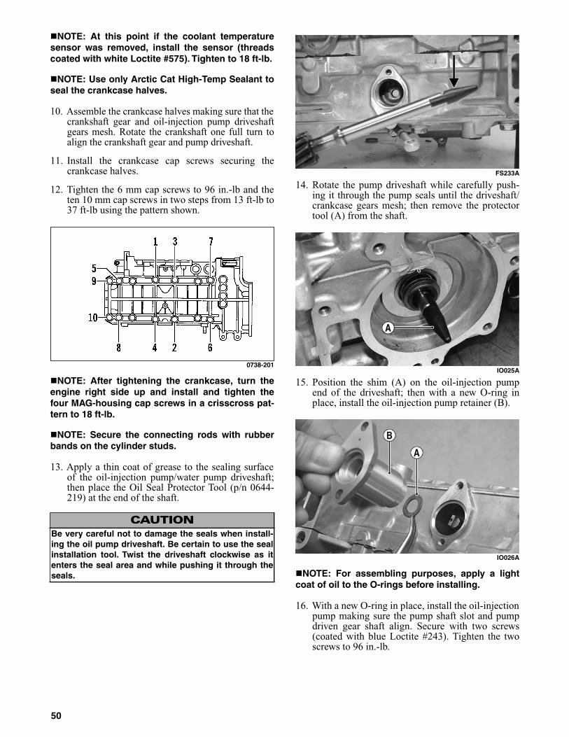
NOTE: At this point if the coolant temperaturesensor was removed, install the sensor (threadscoated with white Loctite #575). Tighten to 18 ft-lb.
NOTE: Use only Arctic Cat High-Temp Sealant toseal the crankcase halves.
10. Assemble the crankcase halves making sure that thecrankshaft gear and oil-injection pump driveshaftgears mesh. Rotate the crankshaft one full turn toalign the crankshaft gear and pump driveshaft.
11. Install the crankcase cap screws securing thecrankcase halves.
12. Tighten the 6 mm cap screws to 96 in.-lb and theten 10 mm cap screws in two steps from 13 ft-lb to37 ft-lb using the pattern shown.
0738-201
NOTE: After tightening the crankcase, turn theengine right side up and install and tighten thefour MAG-housing cap screws in a crisscross pat-tern to 18 ft-lb.
NOTE: Secure the connecting rods with rubberbands on the cylinder studs.
13. Apply a thin coat of grease to the sealing surfaceof the oil-injection pump/water pump driveshaft;then place the Oil Seal Protector Tool (p/n 0644-219) at the end of the shaft.
FS233A
14. Rotate the pump driveshaft while carefully push-ing it through the pump seals until the driveshaft/crankcase gears mesh; then remove the protectortool (A) from the shaft.
IO025A
15. Position the shim (A) on the oil-injection pumpend of the driveshaft; then with a new O-ring inplace, install the oil-injection pump retainer (B).
IO026A
NOTE: For assembling purposes, apply a lightcoat of oil to the O-rings before installing.
16. With a new O-ring in place, install the oil-injectionpump making sure the pump shaft slot and pumpdriven gear shaft align. Secure with two screws(coated with blue Loctite #243). Tighten the twoscrews to 96 in.-lb.
CAUTIONBe very careful not to damage the seals when install-ing the oil pump driveshaft. Be certain to use the sealinstallation tool. Twist the driveshaft clockwise as itenters the seal area and while pushing it through theseals.
50

17. Position the ceramic/rubber seal retainer and sealinto the back side of the water pump impeller withthe ceramic face of the seal directed out.
CM168
18. Using both thumbs, press the seal into positionmaking sure its marked side is positioned towardsthe rubber seal cup; then apply a thin coat ofgrease to the seal outer surface.
CM169
19. Place the impeller into position and secure with acap screw and washer. Be sure the rubber side ofthe washer is lubricated with a light coat of greaseand directed toward the impeller. Apply blue Loc-tite #243 to the threads of the cap screw andtighten to 108 in.-lb.
NOTE: For assembling purposes, lubricate therubber side of the washer before installing.
20. Apply high-temperature sealant to the crankcase/water pump cover seam; then install the dowelpins into the crankcase.
FC133A
NOTE: Do not allow sealant into the breather holein the crankcase. If sealant gets into the hole, care-fully remove before proceeding.
FC072B
FC072A
NOTE: Sealant is only required on the crankcaseseam.
21. Position the O-ring into the water pump cover;then install the cover. Secure with six screws; thenusing the pattern shown, tighten to 96 in.-lb.
NOTE: Lubricating the O-ring with a light coat ofgrease will help keep the O-ring in place.
CAUTIONBe sure the oil-injection pump/water pump driveshaftis properly aligned with the slot of the oil-injectionpump. The pump will be damaged if these two compo-nents are not aligned.
CAUTIONWhen installing the seal into the impeller, assure thatall components are clean and free of any dirt or othercontaminents.
CAUTIONIf the rubber side of the washer is not positionedtoward the impeller, a coolant leak will result.
51

FC134
0742-304
22. Noting the alignment dots, install the thermostatcap with thermostat. Secure the cap with capscrews and tighten to 96 in.-lb.
FC078A
FC073
23. With new gaskets in place, install the reed valveassemblies; then secure the intake flanges in acrisscross pattern to 96 in.-lb.
24. Install the dowel pins into the crankcase; thenplace the cylinder base gasket into position on thecrankcase.
25. Install the piston rings on each piston so the letteron the top (inclined surface) of each ring faces thedome of the piston.
726-306A
26. Apply oil to the connecting-rod small end bear-ings; then install the small-end bearings. Install awasher on each side of the connecting rod.
TZ068
NOTE: The shoulder side of the washer mustseat to the needle bearing.
FC075
CAUTIONIncorrect installation of the piston rings will result inengine damage.
52

27. Place each piston over the connecting rod so theindicator dot on each piston will point toward theintake/exhaust ports; then secure with an oiled pis-ton pin.
NOTE: The indicator dot is found on the pistondome top.
FC079A
28. Install the new circlips so the open end is directedeither up or down.
CM195B
NOTE: To aid in the circlip installation, install thecirclip to the inside of the piston before installingthe connecting rod.
29. Rotate each piston ring until the ring ends areproperly positioned on either side of the ringkeeper; then apply oil to the piston assemblies andcylinder bores. Remove the rubber bands or hosesfrom the connecting rods.
30. In turn on each cylinder, place a piston holder (orsuitable substitute) beneath the piston skirt andsquare the piston in respect to the crankcase; thenusing a ring compressor or the fingers, compressthe rings and slide the cylinder over the piston.Remove the piston holder and seat the cylinderfirmly onto the crankcase.
NOTE: The cylinders should slide on easily. DONOT force the cylinders on.
FC076
31. Secure each cylinder by installing the eight nuts.DO NOT TIGHTEN AT THIS TIME.
32. Install the oil-injection hoses and secure with theclamps; then place the lower check-valve assem-bly into position and secure with the gaskets andunion cap screw. Tighten securely.
33. Secure the cylinders (from step 31) by tighteningthe cylinder base nuts to 44 ft-lb in three stepsusing the appropriate pattern shown.
0742-746
34. Install the two cylinder O-rings on the top of eachcylinder making sure they are correctly positionedin the grooves.
FC077
NOTE: Lubricating the O-ring with a light coat ofgrease will help keep the O-ring in place.
CAUTIONMake sure the circlips are firmly seated and the openend is directed either up or down before continuingwith assembly.
53

35. Place new O-rings onto each of the head capscrews. Place four of these cap screws into the cyl-inder head. Thread the spark plugs in part way;then while holding the head above the cylinder,carefully start and finger-tighten all four capscrews while observing the cylinder O-rings tomake sure they remain in position. Slowly placethe head into position on top of the O-rings. Startand finger-tighten the remaining cap screws beingvery careful not to move the cylinder head.
36. From step 35 in two steps, tighten the 6 mm capscrews to 96 in.-lb and the 8 mm cap screws to 19ft-lb using the pattern shown. Tighten the sparkplugs to 19 ft-lb.
0738-204
NOTE: After tightening the 8 mm cap screws,tighten the two remaining 6 mm cap screws to 96in.-lb.
NOTE: Lubricating the O-ring with a light coat ofgrease will help keep them seated in the groovesof the cylinder.
NOTE: At this point, pressure test the engine.
37. Secure the stator plate to the crankcase with theAllen-head cap screws (coated with blue Loctite#243) and tighten to 96 in.-lb.
FC021
38. Secure the ignition timing sensor with screwscoated with blue Loctite #243. Tighten to 48 in.-lb.Install the stator assembly with wires and a grom-met into the crankcase and secure with the Allen-head screws (coated with blue Loctite #243).Tighten to 96 in.-lb.
FC018
39. Install the key in the crankshaft.
40. Thread two puller bolts into the flywheel; thenslide the flywheel onto the crankshaft making surethe keyways match. Remove the puller bolts.
NOTE: Before installing the flywheel, be sure towipe the crankshaft and flywheel tapers cleanusing a clean towel.
41. Apply red Loctite #271 to the threads of the fly-wheel cap screw; then finger-tighten with a largeflat washer. DO NOT TIGHTEN AT THIS TIME.
FC080
42. Place the starter pulley in position; then looselysecure the starter pulley with three cap screws.Secure the pulley while using the spanner wrenchand tighten the three cap screws evenly to 19 ft-lb.
FC081
43. Using the spanner wrench, tighten the flywheelcap screw (from step 41) to 50 ft-lb.
54

Installing Engine
1. With the spacer (A) and related cap screws prop-erly oriented, install the lower MAG-side andPTO-side engine brackets to the crankcase; theninstall the left-side mounting bracket to the mag-neto housing and tighten all cap screws (coatedwith blue Loctite #243) to 40 ft-lb.
744-859A
2. Place the engine into the chassis from the MAG-side; then position the engine to the mountinglocations in the chassis. In order install the rearPTO-side cap screw (A) and cap screw (B) secur-ing the upper MAG-side engine bracket to thechassis. Tighten cap screws only until snug.
744-864A
3. With the engine mount spacer (E) in place, installcap screws (C) and (D) securing the front MAG-side and PTO-side engine mounting brackets tothe chassis.
4. With the mounting hardware installed, tighten thecap screws (A) through (D) (coated with blue Loc-tite #243) to 40 ft-lb; then install the torque bum-per.
5. Install the oil-injection pump cable; then securethe cable with the E-ring and jam nuts.
IO046A
6. Connect the two coolant hoses to the elbow fit-tings of the crankcase and tighten the hose clamps;then install the coolant hose and vent hose to thecylinder head and secure with hose clamps.
IO045A
IO044A
7. Install the throttle body assembly into the intakeflanges; then tighten the flange clamps securely.
CAUTIONWhen installing the assembly, it is advisable to havethe flange clamps loose enough to slide forward fromthe mounting location to avoid damaging the clamps.
55
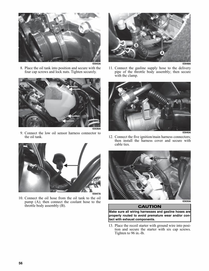
IO043A
8. Place the oil tank into position and secure with thefour cap screws and lock nuts. Tighten securely.
IO036A
9. Connect the low oil sensor harness connector tothe oil tank.
IO047A
10. Connect the oil hose from the oil tank to the oilpump (A); then connect the coolant hose to thethrottle body assembly (B).
IO048A
11. Connect the gasline supply hose to the deliverypipe of the throttle body assembly; then securewith the clamp.
IO040A
12. Connect the five ignition/main harness connectors;then install the harness cover and secure withcable ties.
IO035A
13. Place the recoil starter with ground wire into posi-tion and secure the starter with six cap screws.Tighten to 96 in.-lb.
CAUTIONMake sure all wiring harnesses and gasline hoses areproperly routed to avoid premature wear and/or con-tact with exhaust components.
56

IO034A
14. Lubricate the drive clutch bolt with a light film ofoil; then place the drive clutch into position on thecrankshaft and secure with the cap screw and lockwasher. Tighten to specifications.
NOTE: Before installing the drive clutch, be sureto wipe both the crankshaft taper and clutchmounting taper clean using a clean towel.
15. Install the driven pulley (with inner O-ring), key,and stub shaft. Secure with a cap screw andwasher. Tighten to specifications.
16. Check drive clutch/driven pulley alignment.
17. Using Drive Belt Deflection Tool (p/n 0644-424),install the drive belt so the part number can beread; then roll the belt back and forth while closingthe sheaves allowing the sheaves to fully close.Verify proper drive belt deflection.
743-067B
18. Apply a thin coat of high-temperature siliconesealant to each exhaust port; then install theexhaust gaskets.
19. Apply a thin coat of high-temperature siliconesealant to the mating surfaces of the exhaust mani-fold; then install the exhaust manifold and securewith flange nuts. Tighten the nuts in a crisscrosspattern to 17 ft-lb.
20. Install the resonator and secure it to the chassiswith the springs and hairpin clip.
IO033A
21. Install the expansion chamber and secure with thesprings; then install the link to the upper spar withcap screw and tighten to 96 in.-lb.
IO032A
NOTE: When installing the exhaust manifoldsprings, the long hook portion of the spring mustbe attached to the exhaust manifold or prematurespring failure will result.
22. With the front of the snowmobile elevated, addcoolant until coolant is visible at the filler neck.Start the engine and run the engine up to operatingtemperature and inspect for any signs of coolant orgas leaks; then turn the engine off and add coolantif necessary.
23. Test drive or run the snowmobile and recheck thecoolant level after 5-6 minutes. Tighten the driveclutch cap screw to specifications.
CAUTIONWhen installing the drive clutch, do not tighten theclutch cap screw with any kind of impact tool Tightencap screw using a hand torque wrench only. Failure todo so could result in stationary sheave damage.
CAUTIONIf the engine had a major overhaul or if any major com-ponent was replaced, proper engine break-in proce-dures must be followed. If the proper engine break-inprocedures are not followed, severe engine damagemay result.
57

INDIVIDUAL EFI COMPONENTS
NOTE: With the Arctic Cat EFI System, the ECUmust receive the proper current output from fourcoils (two charge coils, an injector coil, and a fuelpump coil) to function as designed. If a problemexists, these coils should be checked using thefollowing procedures.
NOTE: To aid in testing the EFI system, refer tothe EFI Analyzer Usage Manual with EFI Analyzer.
Injector Coil Resistance Test
The injector coil located on the stator powers the twoinjectors.
1. Disconnect the double-wire plug with two blue/white leads from the stator to the ECU.
2. Set the meter selector to the OHMS scale.
3. Connect a meter lead to each of the blue/whiteleads. The meter must show 15.2-22.8 ohms.
NOTE: If reading is not within the specification,recheck to confirm test results. If still out of toler-ance, replace the stator.
NOTE: If the resistance test is good, a peak read-ing voltage test should also be made.
Fuel Pump Coil Resistance Test
The fuel pump coil powers the fuel pump through theECU.
NOTE: With the engine running, there should12.3-12.9 DC volts supplied to the fuel pump foroperation. To test fuel pump coil resistance, usethe following procedure.
1. Disconnect the double-plug with the two orangewires from the ECU.
2. Set the meter selector to the OHMS scale. Connecta meter lead to each of the two orange leads.
3. The meter must show 1.52-2.28 ohms.
NOTE: If reading is out of tolerance, recheck toconfirm reading. If still out of tolerance, replacethe stator.
NOTE: If the resistance test is good, a peak read-ing voltage test should also be made.
Lighting Coil Resistance Test
The lighting coil located on the stator provides ACpower to the lighting system and accessories throughthe regulator/rectifier. To test the lighting coil resis-tance, follow this procedure.
1. Disconnect the 3-wire connector at the engine.
2. Set the meter selector to the OHMS scale.
3. Test between the two yellow leads.
4. The meter must show 0.08-0.12 ohm.
NOTE: If reading is out of tolerance, recheck toconfirm reading. If still out of tolerance, replacethe stator.
Activating ECU Memory
1. Connect the analyzer test harness to the ECU diag-nostic connector.
2. Connect the analyzer test harness red and blackleads to a 12-volt battery.
3. Turn the analyzer switch ON.
4. Press the analyzer MENU SELECT buttonsrepeatedly until KOKUSAN appears on the dis-play. Once the word KOKUSAN appears on thedisplay, press the TEST button. The analyzer isnow set up to test the EFI system.
5. Press the analyzer MENU SELECT buttonsrepeatedly until the words Memory Problem Diag-nosis Test appears on the display.
6. Press the analyzer TEST button. If all sensors aregood, SENSORS ALL O.K. will appear on thedisplay. If any of the sensors have intermittentlyfailed or are faulty, they will appear on the display.Proceed then to checking the faulty sensor individ-ually as covered in this section.
NOTE: Once problem areas have been deter-mined, always check the component(s) for cleanand tight connections.
7. To erase the memory of the ECU, press the TESTbutton once again; then push the MENU SELECTbuttons until Diagnosis Memory Clear appears onthe display. Turn the analyzer OFF and then backON again. Reselect KOKUSAN mode; then pro-ceed to the Memory Problem Diagnosis Test andpush the TEST button. The display should indicateSENSORS ALL O.K. indicating the memory hasbeen cleared.
8. Disconnect the analyzer test harness from the ECUdiagnostic connection.
Removing ECU
1. Disconnect the battery; then disconnect the wiringharness lead from the ECU.
2. Remove the two lock nuts and screws securing theECU to the upper spar.
3. Remove the ECU.
Installing ECU
1. Secure the ECU to the upper spar with the screwsand lock nuts.
Memory Problem Diagnosis Test
58
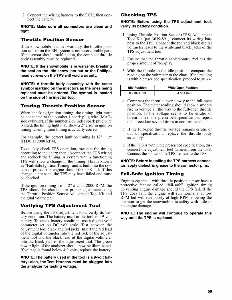
2. Connect the wiring harness to the ECU; then con-nect the battery.
NOTE: Make sure all connectors are clean andtight.
Throttle Position Sensor
If the snowmobile is under warranty, the throttle posi-tion sensor on the EFI system is not a serviceable part.If the sensor should malfunction, the complete throttlebody assembly must be replaced.
NOTE: If the snowmobile is in warranty, breakingthe seal on the idle screw jam nut or the Phillips-head screws on the TPS will void warranty.
NOTE: A throttle body assembly with the samesymbol marking on the injectors as the ones beingreplaced must be ordered. The symbol is locatedon the side of the injector top.
Testing Throttle Position Sensor
When checking ignition timing, the timing light mustbe connected to the number 1 spark plug wire (MAG-side cylinder). If the number 2 cylinder spark plug wireis used, the timing light may show a 2° error in ignitiontiming when ignition timing is actually correct.
For example, the correct ignition timing is 12° ± 2°BTDC at 2000 RPM.
To quickly check TPS operation, measure the timingaccording to the chart; then disconnect the TPS wiringand recheck the timing. A system with a functioningTPS will show a change in the timing. This is knownas “Fail-Safe Ignition Timing” and is built into the sys-tem to protect the engine should the TPS fail. If thischange is not seen, the TPS may have failed and mustbe checked.
If the ignition timing isn’t 12° ± 2° at 2000 RPM, theTPS should be checked for proper adjustment usingthe Throttle Position Sensor Adjustment Tool Kit anda digital voltmeter.
Verifying TPS Adjustment Tool
Before using the TPS adjustment tool, verify its bat-tery condition. The battery used in the tool is a 9-voltbattery. To check battery condition, use a digital volt/ohmmeter set on DC volt scale. Test between theadjustment tool black and red jacks. Insert the red leadof the digital voltmeter into the red jack of the adjust-ment tool and the black lead of the digital voltmeterinto the black jack of the adjustment tool. The greenpower light of the analyzer should now be illuminated.If voltage is found below 4.9 volts, replace the battery.
NOTE: The battery used in the tool is a 9-volt bat-tery; also, the Test Harness must be plugged intothe analyzer for testing voltage.
Checking TPS
NOTE: Before using the TPS adjustment tool,verify its battery condition.
1. Using Throttle Position Sensor (TPS) AdjustmentTool Kit (p/n 3639-891), connect its wiring har-ness to the TPS. Connect the red and black digitalvoltmeter leads to the white and black jacks of theTPS adjustment tool.
2. Ensure that the throttle cable/control rod has theproper amount of free-play.
3. With the throttle in the idle position, compare thereading on the voltmeter to the chart. If the readingis within prescribed specification, proceed to step 4.
4. Compress the throttle lever slowly to the full-openposition. The meter reading should show a smoothrise in voltage all the way to the full-open throttleposition. If the voltage seems to be erratic ordoesn’t meet the prescribed specification, repeatthis procedure several times to confirm results.
5. If the full-open throttle voltage remains erratic orout of specification; replace the throttle bodyassembly.
6. If the TPS is within the prescribed specification, dis-connect the adjustment tool harness from the TPS.Connect the snowmobile TPS harness to the TPS.
NOTE: Before installing the TPS harness connec-tor, apply dielectric grease to the connector pins.
Fail-Safe Ignition Timing
Engines equipped with throttle position sensor have aprotective feature called “fail-safe” ignition timingpreventing engine damage should the TPS fail. If theTPS does fail, the engine will run normally at lowRPM but will run poorly at high RPM allowing theoperator to get the snowmobile to safety with little orno engine damage.
NOTE: The engine will continue to operate thisway until the TPS is replaced.
Idle Position Wide-Open Position
0.710-0.818 3.472-4.048
59

Testing Fuel Injector Resistance
IO031
1. Disconnect the fuel injector wiring harness.
2. Set the meter selector to the OHMS scale.
3. Test between the two injector terminals. Test spec-ification is 10-14 ohms.
CM039
4. If not within specifications, replace the injector.
Removing Fuel Injector
1. Loosen the clamp securing the fuel supply hose tothe fuel rail; then remove the hose from the fuelrail.
2. Disconnect the wiring harness from each injector.
3. Remove the screws securing the injector deliverypipe to the throttle body assembly; then removethe pipe from the injectors.
4. Remove the fuel injectors from the throttle bodyassembly.
CM203A
Installing Fuel Injector
1. Apply a light coat of oil to all O-rings; then installthe upper and lower O-rings onto each injector.
2. Install the injectors into the throttle body assembly.
3. Place the injector delivery pipe into position on thethrottle body assembly and secure with twoscrews.
4. Connect the fuel delivery hose to the fuel rail andsecure with a clamp.
NOTE: When securing the fuel delivery hose,position the clamp as shown.
729-325A
5. Connect the wiring harness to the injectors makingsure the number 1 harness is connected to theMAG-side injector.
CAUTIONThe fuel supply hose may be under pressure. Place anabsorbent towel around the connection to absorb fuel;then remove the hose slowly to release the pressure.
60

Testing Ignition Timing Sensor Resistance
0729-627
NOTE: This sensor is located inside the magnetocase next to the flywheel, and the recoil starter andthe flywheel must be removed to access the sensor.
1. Disconnect the sensor connector (green/white andbrown/green) from the ECU.
2. Set the selector in the OHMS position; then con-nect the meter leads to the sensor leads.
3. Sensor resistance must be 101 ohms ± 20%.
Electric Fuel Pump
1. Remove the hardware securing the console to thegas tank and frame; then move the console out ofthe way.
2. Disconnect the fuel pump from the main wiringharness.
3. Connect the positive lead of a 12-volt power sup-ply to the red wire and the negative lead of the 12-volt power supply to the black wire.
4. The pump should operate (it would be heard run-ning).
NOTE: If the fuel pump fails to operate, the pumpis defective and must be replaced.
Fuel Pressure Regulator
1. Using the EFI Fuel Pressure Test Kit (p/n 0644-571), connect the tester to the delivery pipe andgasline hose.
AO053
NOTE: A short piece of 3/8 in. I.D. hose will beneeded for this procedure.
2. Pressurize the regulator to 2.0-2.2 kg/cm² (28-31.3psi). Turn the pressure tester shut off valve to theOFF position. Observe the gauge for several min-utes and note any loss of pressure. If pressurebegins to drop, the cause may be a ruptured dia-phragm, worn spring, or leaking valve. If the regu-lator fails to build or maintain pressure, the fuelpump assembly must be replaced.
NOTE: If the pressure drops, check the hose con-nections to ensure no leaks exist.
Testing Coolant Temperature Sensor Resistance
NOTE: The coolant temperature sensor is verysensitive to temperature change. Before the resis-tance test is conducted, the coolant temperaturemust be known. If the engine has been operatedrecently and the coolant is warm, the resistancewill measure lower than if the coolant was at roomtemperature or colder. For accurate test results,check the coolant temperature in the filler neckusing a thermometer.
1. Disconnect the coolant temperature sensor wiringharness from the main harness.
2. Set the meter selector to the OHMS position andtest the resistance between the two leads from thesensor.
3. Compare the resistance reading to the Voltage/Resistance Chart - Coolant Temperature in thismanual. If resistance is not within the specifica-tion, replace the sensor.
NOTE: A coolant temperature sensor voltage testcan be made using the EFI Analyzer.
NOTE: The coolant temperature sensor is locatedat the lower half of the crankcase. To remove thesensor, the engine must be removed.
CAUTIONThe fuel supply hose may be under pressure. Place anabsorbent towel around the connection to absorb fuel;then remove the hose slowly to release the pressure.
61

Testing Air Temperature Sensor Resistance
NOTE: The component temperature must beknown before conducting this test. Allow theengine to reach room temperature.
1. Disconnect the wiring harness from the air temper-ature sensor.
AO135D
2. Set the meter selector in the OHMS position andtest the two leads located in the sensor connector.Compare with the Voltage/Resistance Chart - AirTemperature in this manual.
NOTE: The air temperature sensor utilizes athermistor, which is very sensitive to temperaturechanges. Resistance will change as temperaturevaries.
Removing Air Temperature Sensor
1. Disconnect the wiring harness from the air temper-ature sensor.
2. Using a standard screwdriver, pry the sensor endto end to remove it from the air silencer. Accountfor two push pins.
Installing Air Temperature Sensor
1. Place the sensor into position in the air silencerand secure with push pins.
2. Connect the wiring harness to the air temperaturesensor. Secure the sensor leads with cable ties sothey do not rub on any other components.
Removing Throttle Body
NOTE: The expansion chamber and air silencermust be removed for this procedure.
1. Disconnect the wiring harness from each injectorand from the throttle position sensor connector.
2. Remove the coolant hoses from the throttle bodyassembly and plug them to prevent leakage.
3. Remove the fuel supply hose from the fuel rail.
4. Loosen the flange clamps.
5. Slide the throttle body assembly out of the flanges;then loosen the jam nut securing the throttle cableand remove.
6. Remove the oil pump cable from the oil pump.
7. Remove the throttle body assembly.
Installing Throttle Body
1. Attach the throttle cable to the throttle body.Secure with jam nut.
2. Place the throttle body assembly into position.Make sure the flanges and boots are positionedproperly. Secure with flange clamps.
3. Connect the oil pump cable to the oil pump andsecure with the jam nuts.
NOTE: The coolant hoses must be connectedfirst; then the throttle body assembly must beinstalled.
4. Secure the coolant hoses to throttle body assem-bly.
5. Connect the fuel supply hose to the fuel rail.
729-325A
6. Connect the wiring harness to each injector andthrottle position sensor.
NOTE: Install the air silencer and the expansionchamber.
7. Place the rear of the snowmobile on a shieldedsafety stand and start the engine without touchingthe throttle. It may idle slowly and stop. Restartusing the same procedure until the engine startsand builds RPM on its own.
CAUTIONSince the fuel supply hose may be under pressure,remove it slowly to release the pressure. Place anabsorbent towel around the connection to absorb fuel.
CAUTIONThese hoses must be connected to the correct fittings.
62

8. Check the cooling system.
9. Adjust the throttle cable and oil pump cable/syn-chronization as necessary.
INDIVIDUAL FUEL SYSTEM COMPONENTS
Removing Throttle Body Flange
NOTE: The expansion chamber and air-intakesilencer must be removed for this procedure.
1. Loosen the clamps securing the throttle bodyassembly to the throttle body flanges.
2. Remove the throttle body assembly from theflanges.
3. In turn on each flange, remove the two nuts, lockwashers, and flat washers securing the intakeflange to the cylinder; then remove the flange.
Installing Throttle Body Flange
1. Apply a thin coat of high-temperature silicone tothe cylinder side of each flange; then attach eachflange to a cylinder and secure each with two flatwashers, lock washers, and nuts. Tighten to 96 in.-lb.
2. Install the flange clamps on the flanges; then placethe throttle body assembly into the flanges andsecure with the clamps.
3. Secure all wires and hoses with cable ties.
Removing Throttle Cable
1. Loosen the throttle cable adjuster at the bracket.
2. Remove the throttle cable from the pulley on thethrottle body lever shaft.
3. Remove the E-clip securing the oil-injection cableto the oil-injection pump control arm. Account fora washer.
4. Loosen the oil-injection cable jam nuts.
5. Remove the handlebar pad.
6. Remove the cable ties securing the throttle cable.
7. Remove the throttle cable ends from the throttlelever and from the throttle control housing.
Installing/adjusting Throttle Cable
1. Install the throttle cable into the throttle switchassembly making sure the cable snaps into place.
2. Install the throttle cable end on the throttle lever.
3. Route the throttle cable from the throttle switchassembly to the throttle body assembly and oil-injection pump; avoid any sharp bends or movingcomponents.
4. Attach the throttle cable to the pulley on the throt-tle body shaft.
5. Install the oil-injection cable adjuster on the oil-injection pump; secure with the jam nuts.
6. Install the oil-injection cable on the control arm;secure with a washer and E-clip.
7. Secure the throttle cable to the handlebar andsteering post with cable ties.
8. Install the handlebar pad.
9. Adjust the throttle cable tension by turning the jamnuts in the appropriate direction until 0.030-0.060in. free-play exists in the throttle lever and the but-terfly completely opens and closes. Tighten thejam nuts securely.
741-518A
10. Synchronize the oil-injection pump.
CAUTIONWhen installing the throttle bodies, make sure thegasline hose is properly routed to avoid prematurewear and/or contact with exhaust components.
CAUTIONCompress the throttle control lever to ensure freemovement. If the throttle cable sticks or binds, correctthe problem before starting the engine.
63

NOTES
64

Troubleshooting Fuel System
Removing Oil-injection Pump
NOTE: To service the oil-injection pump, theexhaust system and the air silencer must beremoved.
1. Remove the throttle bodies and secure them out ofthe way in an upright position.
2. Disconnect the oil-supply hose from the pump andplug to prevent oil drainage.
3. Remove the oil-delivery hoses from the intakeflanges.
4. Disconnect the oil-injection cable.
5. Remove the two screws securing the oil-injectionpump and retainer to the crankcase.
6. Pull the oil-injection pump away from the retainer/crankcase and account for a gasket/O-ring.
NOTE: Remove the oil-injection pump from thecrankcase only if the O-ring or gasket need to bereplaced.
7. Turn the pump sideways; then remove the lowerunion bolt. Account for two washer gaskets.Remove the pump.
8. Remove the remaining union bolts securing thecheck valves to the pump. Account for the washergaskets.
9. Remove the check valves. Account for two gaskets.
Installing Oil-injection Pump
1. In turn on each front union bolt, install a washergasket, check valve, and washer gasket; theninstall on the oil-injection pump.
2. Place the gasket and oil-injection pump near theengine; then install the lower union bolt through agasket, check valve, and gasket.
3. Position the oil-injection pump on the engine mak-ing sure the oil-injection pump gear is correctlyaligned with the oil-injection pump drive gear.
4. Secure the pump with two screws (coated withblue Loctite #243). Tighten screws to 96 in.-lb.
5. Connect the oil-delivery hoses to the intakeflanges. Secure with clamps.
6. Connect the oil-injection cable to the pump andsecure.
7. Connect the oil-supply hose to the oil-injectionpump inlet fitting. Secure with the clamp.
8. Bleed the oil-injection system.
9. Check the oil-injection system synchronization(see Synchronizing Oil-Injection Pump). Tightenthe jam nuts securely.
NOTE: Install the exhaust system and the airsilencer.
10. Install the throttle bodies.
Synchronizing Oil-Injection Pump
NOTE: The oil pump cable adjuster is located atthe juncture of the throttle cable.
742-331A
Problem: Too RichCondition Remedy
1. Diagnostic trouble code activated2. Fuel pressure too high3. Fuel return hose obstructed4. Injectors leaking
1. Replace problem sensor2. Replace regulator3. Service — replace hose — remove obstruction4. Replace injectors
Problem: Too LeanCondition Remedy
1. Diagnostic trouble code activated2. Fuel pressure too low3. Vent hose obstructed4. Fuel filter(s) obstructed
1. Replace problem sensor2. Replace regulator/fuel pump3. Remove obstruction4. Replace fuel filter(s)
CAUTIONUse a 100:1 fuel mixture for the following procedure.
65

Inspecting/adjusting/Synchronizing Oil-injection Pump
1. With the engine off, disconnect the throttle cablefrom the throttle lever.
2. Pull the throttle cable to the FULL-OPEN posi-tion; then using a suitable clamping device, securethe cable in this position.
3. Check to be sure the mark on the control arm isaligned with alignment mark on the oil pump boss.
4. If the marks are not aligned, adjust synchroniza-tion by loosening the jam nut(s) on the adjuster.Rotate the jam nuts/adjuster nut until proper align-ment is attained. Tighten jam nut(s).
5. Return the throttle cable to the CLOSED position.
NOTE: Connect the throttle cable to the throttlelever; then adjust the cable/linkage adjusting nutso the throttle lever moves approximately 1/8 in.before the oil-injection pump control arm begins tomove. This ensures the throttle/ignition monitorswitch will function properly and will prevent igni-tion “cut-out” and spark plug fouling at low RPMoperation.
Testing Oil-Injection Pump
NOTE: These tests must be made with the snow-mobile and the oil at a “room” temperature of 20°-30° C (68°-86° F).
1. Disconnect the oil pump cable/control rod fromthe control arm on the pump.
2. Clamp off the oil-supply hose between the oil res-ervoir and oil pump; then remove the supply hosefrom the pump.
3. Attach a suitable length of clear oil-supply hose tothe oil pump; then using Oil Injection Usage Tool(p/n 0644-007), fill the hose with Arctic Cat For-mula SS Semi-Synthetic Oil.
NOTE: Use clear hose when performing this testto simplify the detection of air in the testing equip-ment.
NOTE: Use Arctic Cat Formula SS Semi-SyntheticOil. Use of any other oil will cause inaccurate oilconsumption readings.
NOTE: When filling the oil-supply hose with oil, donot fully insert the usage tool into hose. There mustbe enough room around the tip of the tool and thehose to allow air in the hose to escape.
4. Fill the usage tool with recommended oil to the 0line.
5. Wipe the tip of the tool to remove excess oil; thenattach the tool to the oil-supply hose and removethe bulb.
6. Secure the tool to the oil reservoir by twisting therubber strap one half turn and placing the rubberstrap around the tool and the oil reservoir filler neck.
7. With the control arm secured in the FULL-CLOSED (Idle) position, start the engine and runthe engine at recommended RPM for 3 minutes.Compare the amount of oil used against the speci-fications on the Oil Consumption Specificationschart in Section 1.
NOTE: Before starting the engine, make sure thatno air is present in the testing equipment.
8. With the control arm secured in the FULL-OPENposition (line-to-line), run the engine at recom-mended RPM for 2 minutes. Compare the amountof oil used against the specifications chart.
9. If the oil-injection pump output does not meet thespecifications, see Testing Oil-Injection CheckValves in this section.
10. Disconnect the oil usage tool, remove the plugfrom the reservoir, attach the oil-supply hose to theoil reservoir.
CAUTIONCare must be taken when securing the cable not tokink or damage the cable.
CAUTIONWhenever servicing the oil-injection system, use a100:1 gas/oil mixture in the gas tank to ensure ade-quate engine lubrication. Failure to use the 100:1 mix-ture to the oil-injection system will result in severeengine damage.
CAUTIONAssure that the throttle cable has returned to the fullyclosed (idle) position and has not remained in a partialopen position and moves freely from the open posi-tion to the closed position.
! WARNINGAlways wear safety glasses when performing this test.
! WARNINGKeep hands and clothing away from all moving orrotating parts.
CAUTIONWhenever servicing the oil-injection system, use a 100:1gas/oil mixture in the gas tank to ensure adequateengine lubrication. Failure to use the 100:1 mixture to theoil-injection system will result in severe engine damage.
66
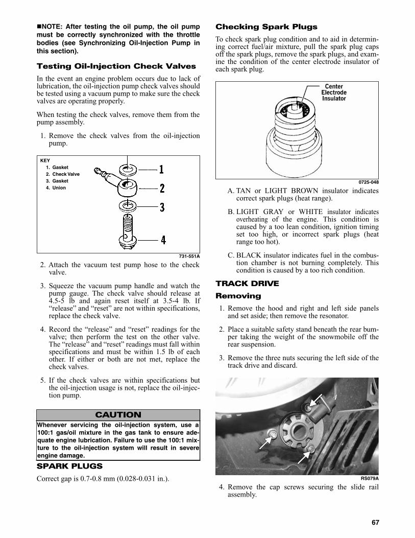
NOTE: After testing the oil pump, the oil pumpmust be correctly synchronized with the throttlebodies (see Synchronizing Oil-Injection Pump inthis section).
Testing Oil-Injection Check Valves
In the event an engine problem occurs due to lack oflubrication, the oil-injection pump check valves shouldbe tested using a vacuum pump to make sure the checkvalves are operating properly.
When testing the check valves, remove them from thepump assembly.
1. Remove the check valves from the oil-injectionpump.
731-551A
2. Attach the vacuum test pump hose to the checkvalve.
3. Squeeze the vacuum pump handle and watch thepump gauge. The check valve should release at4.5-5 lb and again reset itself at 3.5-4 lb. If“release” and “reset” are not within specifications,replace the check valve.
4. Record the “release” and “reset” readings for thevalve; then perform the test on the other valve.The “release” and “reset” readings must fall withinspecifications and must be within 1.5 lb of eachother. If either or both are not met, replace thecheck valves.
5. If the check valves are within specifications butthe oil-injection usage is not, replace the oil-injec-tion pump.
SPARK PLUGS
Correct gap is 0.7-0.8 mm (0.028-0.031 in.).
Checking Spark Plugs
To check spark plug condition and to aid in determin-ing correct fuel/air mixture, pull the spark plug capsoff the spark plugs, remove the spark plugs, and exam-ine the condition of the center electrode insulator ofeach spark plug.
0725-048
A. TAN or LIGHT BROWN insulator indicatescorrect spark plugs (heat range).
B. LIGHT GRAY or WHITE insulator indicatesoverheating of the engine. This condition iscaused by a too lean condition, ignition timingset too high, or incorrect spark plugs (heatrange too hot).
C. BLACK insulator indicates fuel in the combus-tion chamber is not burning completely. Thiscondition is caused by a too rich condition.
TRACK DRIVE
Removing
1. Remove the hood and right and left side panelsand set aside; then remove the resonator.
2. Place a suitable safety stand beneath the rear bum-per taking the weight of the snowmobile off therear suspension.
3. Remove the three nuts securing the left side of thetrack drive and discard.
RS079A
4. Remove the cap screws securing the slide railassembly.
CAUTIONWhenever servicing the oil-injection system, use a100:1 gas/oil mixture in the gas tank to ensure ade-quate engine lubrication. Failure to use the 100:1 mix-ture to the oil-injection system will result in severeengine damage.
KEY1. Gasket2. Check Valve3. Gasket4. Union
67
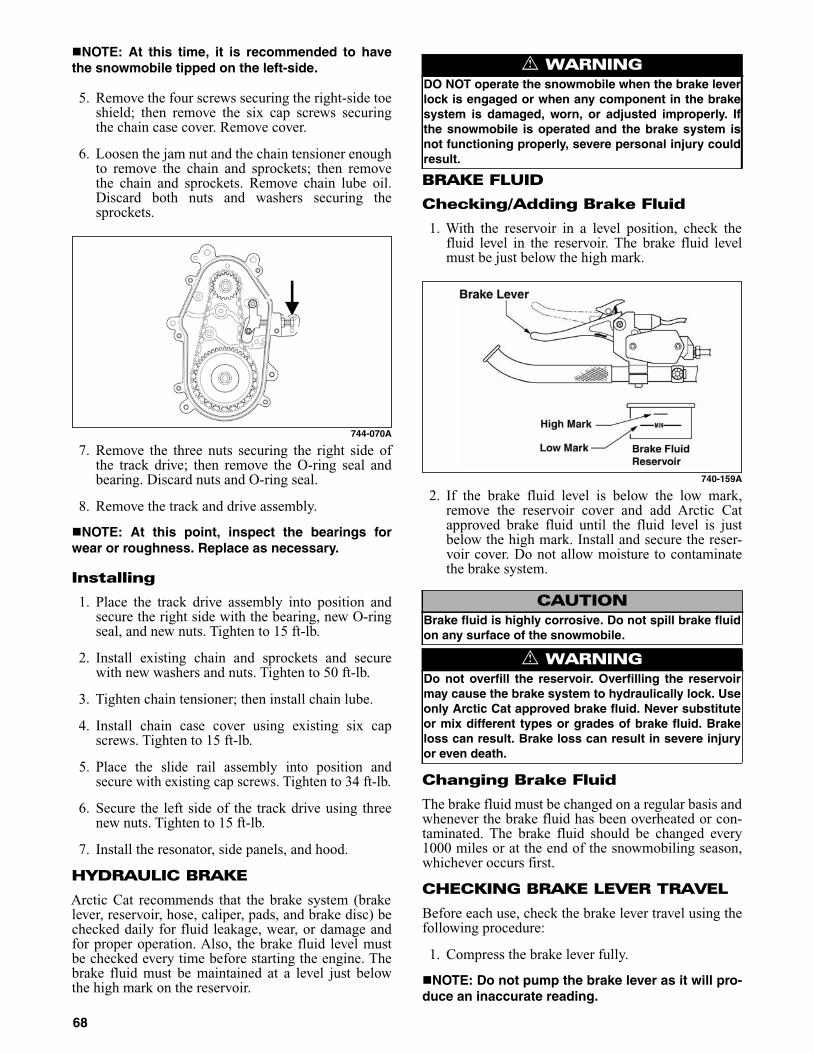
NOTE: At this time, it is recommended to havethe snowmobile tipped on the left-side.
5. Remove the four screws securing the right-side toeshield; then remove the six cap screws securingthe chain case cover. Remove cover.
6. Loosen the jam nut and the chain tensioner enoughto remove the chain and sprockets; then removethe chain and sprockets. Remove chain lube oil.Discard both nuts and washers securing thesprockets.
744-070A
7. Remove the three nuts securing the right side ofthe track drive; then remove the O-ring seal andbearing. Discard nuts and O-ring seal.
8. Remove the track and drive assembly.
NOTE: At this point, inspect the bearings forwear or roughness. Replace as necessary.
Installing
1. Place the track drive assembly into position andsecure the right side with the bearing, new O-ringseal, and new nuts. Tighten to 15 ft-lb.
2. Install existing chain and sprockets and securewith new washers and nuts. Tighten to 50 ft-lb.
3. Tighten chain tensioner; then install chain lube.
4. Install chain case cover using existing six capscrews. Tighten to 15 ft-lb.
5. Place the slide rail assembly into position andsecure with existing cap screws. Tighten to 34 ft-lb.
6. Secure the left side of the track drive using threenew nuts. Tighten to 15 ft-lb.
7. Install the resonator, side panels, and hood.
HYDRAULIC BRAKE
Arctic Cat recommends that the brake system (brakelever, reservoir, hose, caliper, pads, and brake disc) bechecked daily for fluid leakage, wear, or damage andfor proper operation. Also, the brake fluid level mustbe checked every time before starting the engine. Thebrake fluid must be maintained at a level just belowthe high mark on the reservoir.
BRAKE FLUID
Checking/Adding Brake Fluid
1. With the reservoir in a level position, check thefluid level in the reservoir. The brake fluid levelmust be just below the high mark.
740-159A
2. If the brake fluid level is below the low mark,remove the reservoir cover and add Arctic Catapproved brake fluid until the fluid level is justbelow the high mark. Install and secure the reser-voir cover. Do not allow moisture to contaminatethe brake system.
Changing Brake Fluid
The brake fluid must be changed on a regular basis andwhenever the brake fluid has been overheated or con-taminated. The brake fluid should be changed every1000 miles or at the end of the snowmobiling season,whichever occurs first.
CHECKING BRAKE LEVER TRAVEL
Before each use, check the brake lever travel using thefollowing procedure:
1. Compress the brake lever fully.
NOTE: Do not pump the brake lever as it will pro-duce an inaccurate reading.
! WARNINGDO NOT operate the snowmobile when the brake leverlock is engaged or when any component in the brakesystem is damaged, worn, or adjusted improperly. Ifthe snowmobile is operated and the brake system isnot functioning properly, severe personal injury couldresult.
CAUTIONBrake fluid is highly corrosive. Do not spill brake fluidon any surface of the snowmobile.
! WARNINGDo not overfill the reservoir. Overfilling the reservoirmay cause the brake system to hydraulically lock. Useonly Arctic Cat approved brake fluid. Never substituteor mix different types or grades of brake fluid. Brakeloss can result. Brake loss can result in severe injuryor even death.
68

2. Measure the distance between the brake lever andthe handlebar. The distance must be greater than2.54 cm (1 in.).
740-159B
3. If the resultant distance is less than specified, itmust be adjusted.
BLEEDING BRAKE SYSTEM
If the brake lever feels spongy when applied, the brakesystem may need to be bled. To bleed the brake, usethe following procedure:
1. Remove the reservoir cover and fill the reservoirto the high mark with Arctic Cat approved brakefluid.
2. Slide a piece of flexible tubing over the ball of thebleeder valve and direct the other end into a con-tainer.
0737-305
3. Slowly compress the brake lever and hold. Openthe bleeder valve to release the fluid and air. Whenthe fluid stops, close the bleeder valve; thenrelease the brake lever.
4. Repeat step 3 until the brake fluid flows free of airbubbles.
NOTE: It may be necessary to refill the reservoirduring the bleeding process.
5. When the brake fluid is free of all air and the brakelever feels firm when compressed, fill the reser-voir to a level just below the high mark; theninstall and secure the cover. Remove the tube fromthe bleeder valve.
CHECKING/CHANGING BRAKE PADS
The condition of the brake pads must be checked dailyand changed if worn or damaged. To check and changethe brake pads, use the following procedure.
1. Measure the width of both brake pads. The brakepad width must be greater than 3.2 mm (0.125 in.).If the brake pad width is less than specified,replacement of both pads is necessary. Followsteps 2-6 to replace brake pads.
0730-434
2. Remove the pin securing the brake pads to the cal-iper assembly.
3. Remove the brake fluid reservoir cover; thenremove most of the brake fluid from the reservoir.Replace the cover.
NOTE: The above procedure will allow room forthe fluid from the caliper when the pistons arepushed into the caliper for installing new brakepads. Replacing the cover will prevent fluid spill-age.
4. Using a pair of pliers, pull one brake pad out of thecaliper assembly.
NOTE: Changing one pad at a time will preventone piston from pushing out the other piston fromthe caliper.
5. Using a flat-blade tool, slowly and carefully pushthe piston into the caliper.
! WARNINGDo not operate the snowmobile if the compressed dis-tance between the brake lever and the handlebar isless than 2.54 cm (1 in.). Brake loss may occur. Brakeloss can result in severe personal injury.
CAUTIONBrake fluid is highly corrosive. Do not spill brake fluidon any surface of the snowmobile.
! WARNINGUse only Arctic Cat approved brake fluid. Any substi-tute may result in a loss of brakes.
69

6. Position the new brake pad into the caliper.
7. Repeat steps 4-6 for the other pad; then secure thepads with the pin.
8. Remove the reservoir cover and remove theremaining fluid; then fill the reservoir with freshfluid.
9. Pump the brake lever to ensure correct positioningof the brake pads; then release.
10. Fill the reservoir to the proper level with freshbrake fluid.
NOTE: When new brake pads are installed, a“burnishing” process is required. Drive the snow-mobile slowly and compress the brake lever sev-eral times until the pads just start to warm up; thenallow them to cool down. This procedure stabilizesthe pad material and extends the life of the pads.
DRIVE BELT
The drive belt transfers power from the drive clutch tothe driven pulley. If the belt is worn, cracked, orstretched, maximum power will not be transmitted andthe belt could also fail and therefore must be replaced.Periodic checks (at least once a week under normalusage) of two drive belt specifications are essential.
1. Measure the outside circumference of the drivebelt. The belt should be within specifications incircumference.
2. Measure the outside width of the drive belt. Thebelt should be within specifications in width.
3. Check the belt for cracking, fraying, etc.
If any of the specifications or conditions are unsatis-factory, replace the drive belt.
NOTE: Drive belts should be purchased from an.authorized Arctic Cat Snowmobile dealer, as ArcticCat drive belts are made to exact specificationsand of quality material. Belts made by other manu-facturers may not be of the same specifications orquality and, therefore, usage could result in poorperformance and premature belt failure.
Before starting the snowmobile in extremely cold tem-peratures, the drive belt should be removed andwarmed up to room temperature. Once the drive belt isat room temperature, install the drive belt.
Also, drive belts have a break-in period of approxi-mately 25 miles. After installing a new drive belt,drive the snowmobile for 25 miles at 3/4 throttle orless. By revving the engine up and down (but notexceeding 60 mph), the exposed cord on the side of anew belt will be worn down. This will allow the drivebelt to gain its optimum flexibility and will extenddrive belt life.
Removing Drive Belt
1. Remove the tether switch cap and wait for allmoving parts to stop.
2. Set the brake lever lock.
3. Remove the hood; then remove the left-side accesspanel.
4. Using Drive Belt Deflection Tool (p/n 0644-424),thread the tool clockwise into the driven pulleyuntil the movable sheave opens far enough toremove the drive belt.
743-067B
5. When the sheaves are fully apart, pull up on drivebelt and roll belt over stationary sheave until it isfree of the driven pulley.
6. When the belt is free of driven pulley, remove thebelt from the drive clutch.
Installing Drive Belt
1. Place the belt (so the part number can be read)between the sheaves of the drive clutch.
2. With the sheaves fully apart, roll the belt over thestationary sheave.
3. With the drive belt properly positioned in the driveclutch and driven pulley, turn the belt tool counter-clockwise and roll the belt back and forth to allowthe driven pulley sheaves to fully close.
4. After the belt is installed properly, install the left-side access panel and the hood.
5. Release the brake lever lock.
CAUTIONNever run the engine with the drive belt removed.Excessive revving of the engine could result in seri-ous engine damage and drive clutch failure.
! WARNINGNever operate the snowmobile without the accesspanel and hood in place.
70

DRIVEN PULLEY
Disassembling
1. Remove the four torx head cap screws securing thecam to the movable sheave; then grasp the camand by working the movable sheave back andforth, lift it up and off the shaft.
CM086
CM087
NOTE: If changing cam angles, move the cam 90°to its optional position and secure the cam withthe eight torx head cap screws. Tighten to 0.7-0.8kg-m (5-6 ft-lb).
2. Using Driven Pulley Compression Tool (p/n 0644-439), position the tool over the roller assembly;then compress the assembly enough to allow thesnap ring to be removed from the end of the shaft.Remove the snap ring.
CM088
CM089A
NOTE: It is advisable to secure the compressiontool in a vise or to bolt it to a sturdy workbench.
3. Remove the compression tool and account for thesnap ring, spider assembly, spring, and a retainingring.
NOTE: Note the location of the “X” stamped onthe roller assembly for assembling purposes.
4. Remove the movable sheave from the driven pul-ley shaft and account for one spacer.
Cleaning And Inspecting
NOTE: Whenever a part is worn excessively,cracked, or damaged in any way, replacement isnecessary.
1. Using a parts-cleaning solvent, wash grease, dirt,and foreign matter off all components; dry withcompressed air.
2. Remove any drive belt dust accumulation from thestationary sheave, movable sheave, and bushingsusing parts-cleaning solvent only.
3. Inspect the roller assembly for wear or damage.
NOTE: Flat spots or diameter cannot be less than23 mm (0.925 in.).
4. Inspect shaft for nicks or burrs.
5. Using a spring compression scale, measure springrate at proper load heights (secondary springsmeasured at load heights of 2.2 in. and 1.1 in.).
NOTE: If a spring rate measures less than 10% ofspecified load height, it must be replaced.
6. Measure the inside diameter of the movablesheave bushing. Bushing to shaft clearance mustnot exceed 0.25 mm (0.010 in.).
CAUTIONDo not use steel wool or a wire brush to clean com-ponents having a bushing; damage to the bushingwill result.
71

NOTE: If clearance exceeds the limit, the bushingmust be replaced.
Assembling
1. Install the spacer and the movable sheave onto thedriven pulley shaft.
2. Place the retaining ring and spring into the drivenpulley; then place the roller assembly and snapring over the spring.
FS031
3. Position the roller assembly so the “X” mark isdirectly in line with the keyway on the driven pul-ley shaft.
FS033A
4. With Driven Pulley Compressor (p/n 0644-439),compress the roller assembly enough to allow thesnap ring to be properly secured to the shaft.
CM090
NOTE: While compressing the roller assembly, itmay be necessary to work the spider assemblyback and forth to properly mate the splines.
5. With the “X” mark on the movable sheave linedup with the “X” mark on the roller assembly, placethe cam with the desired angle into position; thensecure the cam to the movable sheave with thefour torx head cap screws. Tighten to 0.7-0.8 kg-m(5-6 ft-lb).
CM091B
CM086A
Installing
1. Slide the alignment washers onto the end of thedriven shaft.
2. Install the key in the driven shaft keyway; thenplace the stub shaft into the driven pulley. Placethe driven pulley on the shaft. Align its keywaywith the driven shaft keyway.
NOTE: A small amount of Loctite Anti-SeizeThread Compound (p/n 0678-146) applied to thedriven shaft will aid in future driven pulleyremoval.
3. Secure the driven pulley by installing any align-ment washers, the washer, and cap screw. Tightenthe cap screw to 2.6-3.3 kg-m (19-24 ft-lb).
NOTE: Make sure the keyways match wheninstalling the driven pulley. Arrange washers toallow the least amount of “float” on the drivenshaft. A maximum of 1-2 mm (0.040-0.080 in.) offloat is acceptable.
72

SKI SHOCK ABSORBER SPRINGS
The shock absorber springs have been matched to theshock valving and rear suspension. These springs arethe result of hours of testing and comparison ridingtrying many different combinations of springs andshocks. If there is a need to make changes, there areseveral spring and shock sizes to choose from. Whilemaking these changes, keep the following points inmind.
Heavier/Lighter Springs
1. Using heavier or lighter springs will affect theshock function. Changes in compression orrebound damping may be necessary to attaindesired performance.
2. With heavier springs, the front end will becomemore aggressive in the corners as more weight willbe transferred to the skis when decelerating. Also,more weight is transferred to the rear on accelera-tion and can cause the rear shocks and spring tobottom out.
3. With lighter springs, the front end will generally“ride in” more. This could aid in cornering, butmay cause the chassis to “roll.” Lighter springsgenerally create more pitch change from front toback. This can also aid with traction.
Spring Tension Too Soft
1. Front end bottoms out; hard on front end parts.
2. Less aggressive steering in corners on decelera-tion, and less weight is transferred to the skisbecause of softer springs.
3. Less weight gets transferred to rear of the machineupon acceleration.
NOTE: When softening the ski springs, alsosoften the rear to match entire suspension.
SERVICING ZERO PRO SHOCK ABSORBERS (Ski Shock)
This procedure shows the proper method for servicingthe ski shock absorbers.
NOTE: Some illustrations and photographs usedin the following sub-sections are used for claritypurposes and are not designed to depict actualconditions.
Disassembling
1. Remove the spacers and O-rings from the eyelets.
2. Clean the entire shock assembly with soapy water.Dry the shock assembly with compressed air.
NOTE: If compressed air is not available, useclean towel to dry the shock assembly.
3. Using a 3/32-in. hex key, remove the button-headscrew from the air valve in the shock body.
4. Clamp an inflation needle in a vise; then insert theneedle squarely into center of the nitrogen valve torelease the pressure.
FS274
5. When the shock is fully discharged, pull the needleaway from the reservoir in a straight, smoothmotion.
NOTE: At this point, inspect the FAV3 nitrogenvalve for signs of wear such as holes on the faceof the pellet. Replace if necessary.
6. Clamp the body and eyelet securely in a soft-jawed vise with the shaft side up.
7. Using a 1 3/8-in. wrench, loosen and unscrew thebearing assembly from the shock body.
CAUTIONIf the ski shock spring is adjusted too loose, thespring retainer may fall out. If the spring is adjustedbeyond specification, the spring will coil bind andspring adjuster damage will occur.
! WARNINGBefore starting, read through all of these instructionsfirst to become familiar with the procedure. Make surethe work area is clean and all of the necessary toolsare available. These shocks contain high pressurenitrogen gas. Always use proper safety equipmentsuch as latex gloves and safety glasses when workingon shock absorbers.
CAUTIONUse a soft-bristle brush to remove as much dirt anddebris as possible. Do not pressure wash the shockas this can force water and debris inside causing dam-age to the seals.
! WARNINGWhen using compressed air to dry components,always wear safety glasses.
! WARNINGPoint the air valve away from face and body to avoidinjury when discharging or charging the shock.
73
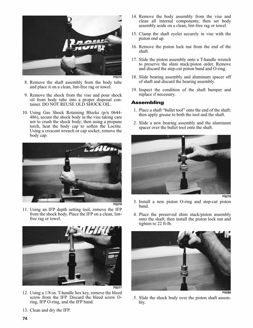
FS275
8. Remove the shaft assembly from the body tubeand place it on a clean, lint-free rag or towel.
9. Remove the shock from the vise and pour shockoil from body tube into a proper disposal con-tainer. DO NOT REUSE OLD SHOCK OIL.
10. Using Gas Shock Retaining Blocks (p/n 0644-486), secure the shock body in the vise taking carenot to crush the shock body; then using a propanetorch, heat the body cap to soften the Loctite.Using a crescent wrench or cap socket, remove thebody cap.
FS276
11. Using an IFP depth setting tool, remove the IFPfrom the shock body. Place the IFP on a clean, lint-free rag or towel.
FS277
12. Using a 1/8-in. T-handle hex key, remove the bleedscrew from the IFP. Discard the bleed screw O-ring, IFP O-ring, and the IFP band.
13. Clean and dry the IFP.
14. Remove the body assembly from the vise andclean all internal components; then set bodyassembly aside on a clean, lint-free rag or towel.
15. Clamp the shaft eyelet securely in vise with thepiston end up.
16. Remove the piston lock nut from the end of theshaft.
17. Slide the piston assembly onto a T-handle wrenchto preserve the shim stack/piston order. Removeand discard the step-cut piston band and O-ring.
18. Slide bearing assembly and aluminum spacer offof shaft and discard the bearing assembly.
19. Inspect the condition of the shaft bumper andreplace if necessary.
Assembling
1. Place a shaft “bullet tool” onto the end of the shaft;then apply grease to both the tool and the shaft.
2. Slide a new bearing assembly and the aluminumspacer over the bullet tool onto the shaft.
FS279
3. Install a new piston O-ring and step-cut pistonband.
4. Place the preserved shim stack/piston assemblyonto the shaft; then install the piston lock nut andtighten to 22 ft-lb.
FS280
5. Slide the shock body over the piston shaft assem-bly.
74

6. Thread the bearing assembly onto the shock bodyand hand-tighten until the O-ring is seated againstthe body.
7. Fully extend the shaft; then clamp the shock in thevise by the shaft eyelet.
8. Fill the shock body with Shock Oil (p/n 5639-240) toapproximately 1/2 in. above the IFP depth setting.
FS281
9. Slowly stroke the shock body to purge air from theshim stack/piston assembly.
10. Remove the shock from the vise; then clamp the“flats” of the bearing housing in the vise with theopen end of the body directed up. Pull the shaftdown to its fully extended position. Add additionaloil as needed.
FS282
11. Lubricate and install the IFP O-ring and pistonband.
12. Insert the IFP into the shock body with the“dished” side directed down.
13. Using an appropriate measuring device, set theIFP depth at 2.26 in.
FS283
14. Lubricate and replace the IFP bleed screw O-ring;then while holding the IFP with a depth settingtool and using a 1/8-in. T-handle hex wrench,install the bleed screw.
FS284
15. Discard the excess oil remaining above the IFP.
16. Lubricate and install the new body cap O-ring.Apply green Loctite #638 to the first two threadsof the shock body; then thread the body cap ontothe body and hand-tighten.
17. Remove the shock from the vise; then clamp theshock in the vise by the body cap eyelet.
18. Using a 1 3/8-in. wrench, tighten the bearing to 75ft-lb.
NOTE: The body cap will also tighten as the bear-ing is tightened.
19. Insert the needle squarely into the center of thenitrogen valve (taking care that the valve isdirected away from face and body) and pressurizethe reservoir to 250 psi.
75

FS285
20. Using a 3/32-in. hex key, install the button-headscrew into the air valve. Dispose of used shock oil.
21. Lubricate and install the O-rings and spacers intothe eyelets.
ADJUSTING REAR TRANSFER ADJUSTER CAMS
The transfer system has seven positions. To make camadjustment, use the following procedure.
741-231A
1. Loosen the Cap Screw (p/n 8020-040) and LockNut (p/n 8047-366) securing the cams to the sliderail. Remove the cap screw.
2. Using a 1/4-in. drive ratchet and extension, rotatethe cams to the desired position.
NOTE: Position 1 allows for the most weighttransfer, and position 7 allows for the least weighttransfer.
NOTE: When setting the cams, the chosen posi-tion must be directed toward the rear arm.
NOTE: Standard cam position is position 5.
3. Install the cap screw and lock nut to secure thecam position; then tighten securely.
LIGHTS
The correct taillight/brakelight bulb is p/n 0409-056.The correct headlight bulbs are p/n 0409-073 and0409-045.
Removing and Installing Taillight/Brakelight Bulb
1. Remove the screws securing the taillight/brake-light lens; then remove the lens.
0743-077
2. Push in on the bulb and rotate it counterclockwiseto remove it from the socket.
3. Install the new bulb in the socket by pushing it inand rotating it clockwise.
4. Install the lens and secure with the screws.
Removing Headlight Bulb
NOTE: The bulb portion of the headlight is frag-ile. HANDLE WITH CARE. When replacing theheadlight bulb, the bulb assembly must first beremoved from the housing. Do not touch the glassportion of the bulb. If the glass is touched, it mustbe cleaned with a dry cloth before installing.
1. Remove the headlight bulb from the headlighthousing and disconnect the wiring harness fromthe bulb.
0743-072
! WARNINGCharge the shock using nitrogen gas only. DO NOTCHARGE WITH ANY OTHER TYPE OF GAS. Doing sowill compromise the performance of the shock andmay be EXTREMELY DANGEROUS.
76

Installing Headlight Bulb
1. Plug the wiring harness into the headlight bulb.
2. Insert the bulb into the headlight housing.
3. Check headlight aim.
SKI WEAR BAR
NOTE: The skis on this snowmobile are notequipped with wear bars. For information on skiwear bars, see the 2011 POGA Reference Guide(p/n 5214-070). Ski wear bars are available froman authorized Arctic Cat Snowmobile dealer.
The ski wear bar is a replaceable bar attached to theunderside of the ski. The purpose of the wear bar is toassist in turning the snowmobile, to minimize ski wear,and to maintain good steering control. If the snowmo-bile is operated primarily in deep snow, ski wear barwear will be minimal; however, if the snowmobile isoperated on terrain where the snow cover is minimal,the ski wear bar will wear faster. To maintain positivesteering characteristics, Arctic Cat recommends thatthe ski wear bars be checked before each use andreplaced if worn beyond 1/2 of the original diameter.Ski wear bars are available from an authorized ArcticCat Snowmobile dealer.
NOTE: Always check the official rules for theappropriate wear bars for the event being partici-pated in.
Removing Ski Wear Bar
1. Remove ice and snow buildup from the ski.
2. With the gas tank nearly empty (less than 1/4 full),lay the snowmobile on its left side. A piece ofcardboard should be used to protect the finish onthe hood and belly pan.
NOTE: Prior to tipping the snowmobile on itsside, apply the brake and set the brake lever lock.
NOTE: When laying the snowmobile on its leftside, properly support the snowmobile on a han-dlebar support stand to keep it from rolling over.
3. Remove the lock nuts securing the wear bar to theski.
0743-185
4. Remove the wear bar from the ski.
Installing Ski Wear Bar
1. Move the wear bar into position on the bottom ofthe ski.
2. Align the wear bar studs with the holes in the ski;then install the lock nuts. Tighten to 11-15 ft-lb.
RAIL WEAR STRIP
Arctic Cat recommends that the wear strips be checkedweekly and replaced as necessary. Measure the wearstrips at 25.4 cm (10 in.) intervals. Wear strips must be10.7 mm (0.42 in.) thick or thicker. If wear strip mea-surements are less than specified, replacement of bothwear strips is necessary to prevent premature track clipwear and possible track damage.
NOTE: The rail wear strips will wear rapidly if thesnowmobile is operated on terrain on which thesnow cover is minimal. Loose snow is required tocool and lubricate the wear strips and preventaccelerated wear.
0744-875
CAUTIONDo not touch the glass portion of the bulb. If the glassportion is touched, it must be cleaned with a dry clothbefore installing.
! WARNINGDo not operate the snowmobile unless headlight beamis adjusted properly. An incorrectly adjusted beam willnot provide the operator the optimum amount of light.
! WARNINGOperating the snowmobile with excessively worn ormissing wear bars may result in a loss of steering con-trol.
77

Performance Tips
Operating a high performance snowmobile requires aspecial attention. Often, a minor adjustment will resultin a large increase in performance. This section isintended to highlight minor conditions that adverselyaffect performance and the adjustments needed to cor-rect them. Be sure, however, to thoroughly read andunderstand this entire manual especially the section onspark plugs, track tension and alignment, and suspen-sion.
DRIVE BELT — This link between the engine anddrive train is often the most neglected component. Thedrive belt must have the proper fit in the drive clutchand driven pulley. Proper fit is when the top surface ofthe drive belt is flush with the top or up to 1/16 in.higher than the driven pulley sheaves (with thesheaves fully closed). If the belt sits below this level,the snowmobile will bog at slow speeds and will havea slower maximum speed. To correct this condition,first determine if the drive belt is within specifications(see Drive Belt section) and replace if worn or toolong. Secondly, always run the drive belt in the samedirection. Installing the drive belt so the part numbercan be read will ensure that the drive belt is always runthe same direction.
DRIVE CLUTCH AND DRIVEN PULLEY —Keeping the drive clutch and driven pulley cleanshould be the primary consideration of the operator.The clutch sheaves can be cleaned of any drive beltaccumulation using a clean cloth and parts-cleaningsolvent. All pivot points can be maintained clean usingcompressed air.
Preparation For Storage
Prior to storing the snowmobile, it must be properlyserviced to prevent corrosion and component deterio-ration. To prepare the snowmobile for storage, ArcticCat recommends the following procedure.
1. Clean the seat cushion with a damp cloth and Arc-tic Cat Vinyl Protectant (p/n 0636-173).
2. Clean the snowmobile thoroughly by hosing dirt,oil, grass, and other foreign matter from the skidframe, tunnel, hood, and belly pan. Allow thesnowmobile to dry thoroughly. DO NOT get waterinto any part of the engine.
3. Place the rear of the snowmobile up on a shieldedsafety stand. Remove the air-intake silencer bootsfrom the throttle bodies.
4. Start the engine and allow to idle. With the engineidling, spray Arctic Cat Engine Storage Preserver(p/n 0636-177) into the throttle bodies until theengine exhaust starts to smoke heavily or until theengine starts to drop in RPM. Turn engine off.
5. Plug the exhaust system outlet with a clean cloth.
6. With the tether switch cap removed:
A. Disconnect the high tension leads from thespark plugs; then remove the plugs, connectthem to the leads, and ground them on the cyl-inder heads.
B. Pour 29.5 ml (1 fl oz) of SAE #30 petroleum-based oil into each spark plug hole and pull therecoil starter handle slowly about 10 times.
C. Install the spark plugs and connect the high ten-sion leads.
7. Fill the gas tank to its rated capacity; then add Arc-tic Cat Fuel Stabilizer (p/n 0638-165) to the gastank following directions on the container for thestabilizer/gasoline ratio. Tighten the gas tank capsecurely.
8. Drain the chain-case lubricant. Remove the chain-case cover and inspect chain, sprockets, and chaintensioner for wear and the chain for proper ten-sion. Install the chain-case cover and seal; thenpour Arctic Cat Transmission Lube (p/n 0636-817) into the oil level stick filler hole according tospecifications.
9. Remove the drive belt from the drive clutch/drivenpulley. Lay the belt on a flat surface or slide it intoa cardboard sleeve to prevent warping or distortionduring storage.
10. Clean and inspect the drive clutch and driven pul-ley.
11. Apply light oil to the upper steering post bushingand shafts of the shock absorbers.
12. Lubricate the rear suspension and bellcranks witha low-temperature grease.
13. Tighten all nuts, bolts, and cap screws making sureall calibrated nuts, bolts, and cap screws are tight-ened to specifications. Make sure all rivets holdingthe components together are tight. Replace allloose rivets.
14. Clean and polish the hood, console, and chassiswith Arctic Cat Hood and Windshield Cleaner/Polish (p/n 0636-174). DO NOT USE SOL-VENTS OR SPRAY CLEANERS. THE PRO-PELLANT WILL DAMAGE THE FINISH.
CAUTIONUse Clutch Puller (p/n 0744-062). Never substitute adifferent puller or drive clutch damage will occur.
CAUTIONNever crank the engine over without grounding thespark plugs. Damage to coils and/or ECU may result.
78
15. If possible, store the snowmobile indoors. Raisethe track off the floor by blocking up the back endmaking sure the snowmobile is secure. Loosen thetrack adjusting bolts to reduce track tension. Coverthe snowmobile with a machine cover or a heavytarpaulin to protect it from dirt and dust.
16. If the snowmobile must be stored outdoors, posi-tion the snowmobile out of direct sunlight; thenblock the entire snowmobile off the ground mak-ing sure the snowmobile is secure. Loosen thetrack adjusting bolts to reduce track tension. Coverwith a machine cover or a heavy tarpaulin to pro-tect it from dirt, dust, and rain.
Preparation After Storage
Taking the snowmobile out of storage and correctlypreparing it for another season will assure many milesand hours of trouble-free snowmobiling. Arctic Catrecommends the following procedure.
1. Clean the snowmobile thoroughly. Polish the exte-rior of the snowmobile.
2. Clean the engine. Remove the cloth from theexhaust system. Check exhaust system and air-intake silencer for obstructions.
3. Inspect all control wires and cables for signs ofwear or fraying. Replace if necessary. Use cableties or tape to route wires and cables away fromhot or rotating parts.
4. Inspect the drive belt for cracks and tears. Checkbelt specifications. Replace if damaged or worn.Install the drive belt.
NOTE: If the old belt is worn but in reasonablecondition, keep it in the tool box as a spare in caseof emergency.
5. Inspect all fuel hoses for deterioration or cracks;replace if necessary. Make sure all connections aretight.
6. Inspect the entire brake system (fluid level, pads,etc.), all controls, headlight, taillight, brakelight,ski alignment, ski wear bars, and headlight aim;adjust or replace as necessary.
7. Inspect the spark plugs. Replace, gap, or clean asnecessary.
8. Adjust the track to the proper tension and align-ment.
NOTE: Prior to tipping the snowmobile on itsside, apply the brake and set the brake lever lock.
9. Check air pressure in the front ski shocks.
10. Verify for properly adjusted throttle cable and oilpump cable.
11. Tighten all nuts, bolts, and cap screws making sureall calibrated nuts, bolts, and cap screws are tight-ened to specifications.
12. If not done during preparation for storage, lubri-cate the rear suspension, spindles, and steeringarms with an all-temperature grease.
Genuine Arctic Cat Products
Arctic Cat Oil - Developed, tested, and proven espe-cially for Arctic Cat Snowmobile engines. Arctic CatOil is the only oil authorized by Suzuki and Arctic Catengineers for use in Arctic Cat Snowmobile engines.Arctic Cat Oil ensures warranty coverage for lubricat-ing related incidents. Arctic Cat Oil comes in strong,handy, recloseable containers.
Transmission Lube - A special formula that reducesfriction and fights corrosion. Arctic Cat TransmissionLube comes in easy-pour, recloseable containers.
Chain Lube - A special formula reduces friction andfights chain case corrosion.
Fuel De-Icer - An isopropyl blend formulated toabsorb water and not adversely affect internal carbure-tor and engine components.
Fuel Stabilizer - Fuel treatment for storage longerthan 60 days. Slows oxidation to prevent gum and var-nish buildup. Engines start easily even after storageperiods exceeding one year. Ideal for use in snowmo-bile gas tanks.
Antifreeze - Pre-mixed ready for use without addingany water. Comes in 1 gallon container.
Hi-Temp Brake Fluid - Recommended for Arctic Cathydraulic brake system.
CAUTIONAvoid storing in direct sunlight and using a plasticcover as moisture may collect on the snowmobilecausing corrosion.
79

Special Tools
To order any special tools, call the Service Departmentat Arctic Cat Inc. 1-800-279-2281.
Ball Hone
p/n: 0644-290 (60-64 mm)p/n: 0644-291 (65-70 mm)p/n: 0644-292 (72-74 mm)p/n: 0644-293 (76-83 mm)p/n: 0644-294 (83-88 mm)p/n: 0644-531 (90-95 mm)p/n: 0644-532 (96-101 mm)p/n: 0644-533 (102-108 mm)Usage: Deglaze Nicosil plated cylinders. All are 320 gritand are recommended for reconditioning Arctic Cat snow-mobile engine cylinders.
0644-291
Flywheel Spanner Wrench
p/n: 0144-007Usage: Hold starter cup while removing/installing fly-wheel nut.
0144-007
Flywheel Puller Insert
p/n: 0644-179Usage: Protect the crankshaft end during flywheelremoval.
0644-179
Flywheel Puller
p/n: 0744-040 (Complete Set)p/n: 0643-086 (Body)p/n: 0643-087 (Bolt)p/n: 0423-482 (6 mm Cap Screw)p/n: 0423-483 (8 mm Cap Screw)Usage: Pull flywheel off crankshaft on all Arctic Cat 2-stroke models.
0744-040
Product ContainerSize
PartNumber
Pkg/Qty
Synthetic APV 2-Cycle Oil 55 gal. 2639-509 1
Synthetic APV 2-Cycle Oil 1 gal. 2639-511 6/1 gal.
Synthetic APV 2-Cycle Oil 16 gal. 2639-510 1
Synthetic APV 2-Cycle Oil 2-1/2 gal. 2639-975 2—2-1/2 gal.
Synthetic APV 2-Cycle Oil 1 qt 2639-512 12/1 qt.
Transmission Lube 2-1/2 gal. 1639-247 1—2-1/2 gal.
Transmission Lube 12 oz 0636-817 12/12 oz
Engine Storage Preserver 12 oz 0636-177 12/12 oz
All-Temp Grease (Lithium) 14-1/2 oz 0636-593 10/14-1/2 oz
Silicone Spray 10 oz 0636-594 12/10 oz
Shock Oil - Light (Fox Racing) 1 qt 4639-345 1 qt
Fuel De-Icer 12 oz 0638-043 12/12 oz
Fuel Stabilizer 8 oz 0638-165 12/8 oz
Hi-Temp Brake Fluid 12 oz 0638-315 6/12 oz
Antifreeze 1 gal. 0638-395 6/1 gal.
Fuel System Cleaner 12 oz 3639-619 1
Shock Oil 1 qt 5639-240 1 qt
80

Crankshaft Bearing Remover
p/n: 0144-302Usage: Remove crankshaft bearings.
0144-302
Oil Seal Protector Tool
p/n: 0644-219Usage: Protect the oil seal when installing the waterpump driveshaft on liquid cooled 2-stroke Arctic Catengines.
0644-219
Piston Pin Puller
p/n: 0644-328 (Complete Set)p/n: 0643-073 (Extractor Nut Only-Small)p/n: 0643-074 (Extractor Nut Only-Medium)p/n: 0643-075 (Extractor Nut Only-Large)p/n: 0643-072 (Threaded T-Handle)Usage: Remove piston pins.
0644-328
Spring Toolp/n: 0644-554Usage: Remove/install exhaust springs.
0644-554
Spring Tool
p/n: 0644-072Usage: Remove/install exhaust springs.
0644-072
Stud Runner
p/n: 0644-018 (6 mm)p/n: 0644-019 (8 mm)p/n: 0644-020 (10 mm)Usage: Install studs on cylinders and crankcase.
0644-020
81
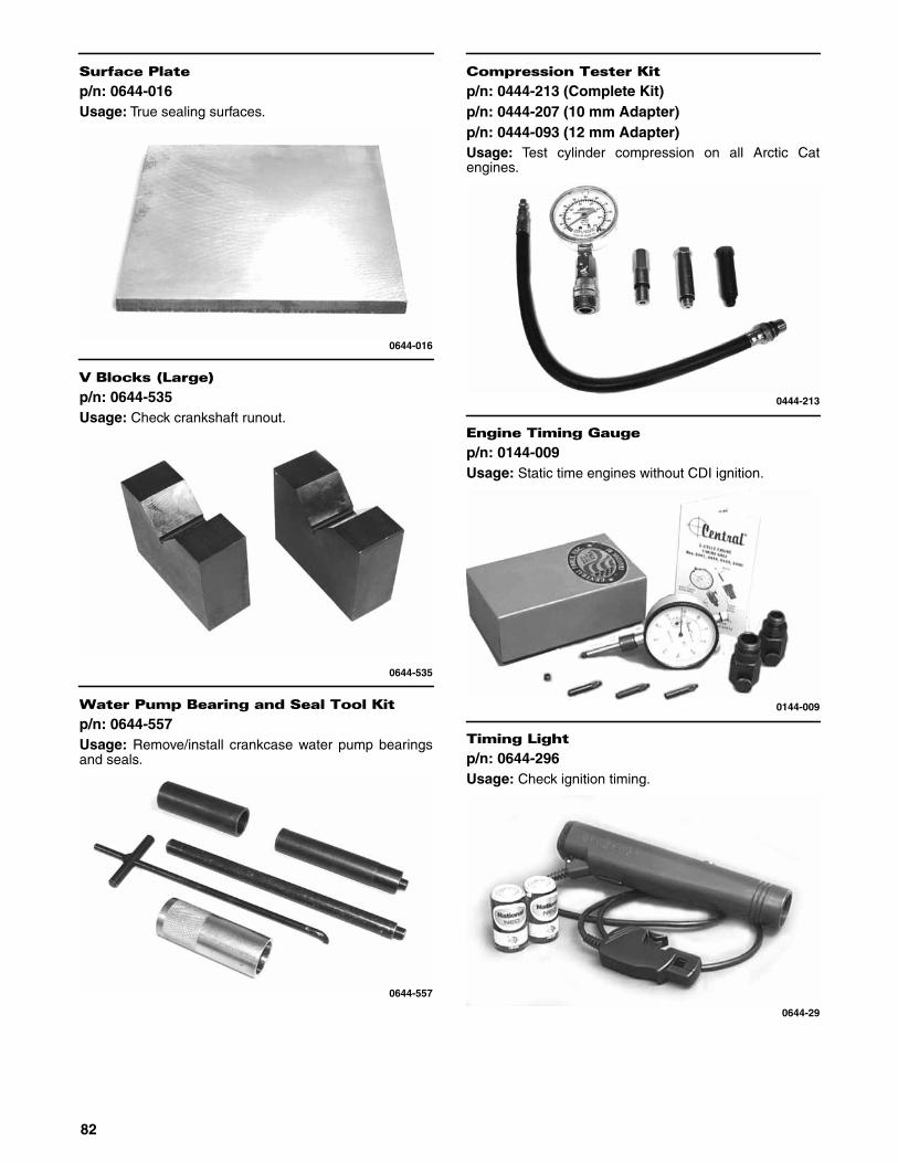
Surface Plate
p/n: 0644-016Usage: True sealing surfaces.
0644-016
V Blocks (Large)
p/n: 0644-535Usage: Check crankshaft runout.
0644-535
Water Pump Bearing and Seal Tool Kit
p/n: 0644-557Usage: Remove/install crankcase water pump bearingsand seals.
0644-557
Compression Tester Kit
p/n: 0444-213 (Complete Kit)p/n: 0444-207 (10 mm Adapter)p/n: 0444-093 (12 mm Adapter)Usage: Test cylinder compression on all Arctic Catengines.
0444-213
Engine Timing Gauge
p/n: 0144-009Usage: Static time engines without CDI ignition.
0144-009
Timing Light
p/n: 0644-296Usage: Check ignition timing.
0644-29
82
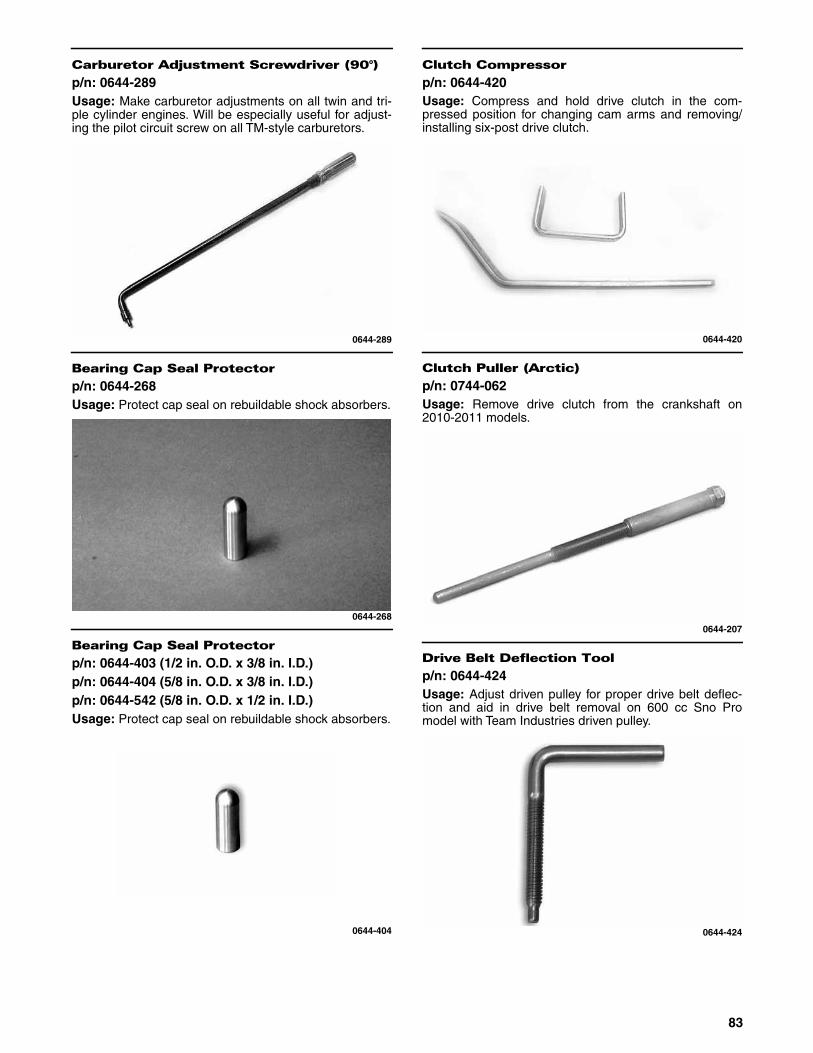
Carburetor Adjustment Screwdriver (90°)
p/n: 0644-289Usage: Make carburetor adjustments on all twin and tri-ple cylinder engines. Will be especially useful for adjust-ing the pilot circuit screw on all TM-style carburetors.
0644-289
Bearing Cap Seal Protector
p/n: 0644-268Usage: Protect cap seal on rebuildable shock absorbers.
0644-268
Bearing Cap Seal Protector
p/n: 0644-403 (1/2 in. O.D. x 3/8 in. I.D.)p/n: 0644-404 (5/8 in. O.D. x 3/8 in. I.D.)p/n: 0644-542 (5/8 in. O.D. x 1/2 in. I.D.)Usage: Protect cap seal on rebuildable shock absorbers.
0644-404
Clutch Compressor
p/n: 0644-420Usage: Compress and hold drive clutch in the com-pressed position for changing cam arms and removing/installing six-post drive clutch.
0644-420
Clutch Puller (Arctic)
p/n: 0744-062Usage: Remove drive clutch from the crankshaft on2010-2011 models.
0644-207
Drive Belt Deflection Tool
p/n: 0644-424Usage: Adjust driven pulley for proper drive belt deflec-tion and aid in drive belt removal on 600 cc Sno Promodel with Team Industries driven pulley.
0644-424
83
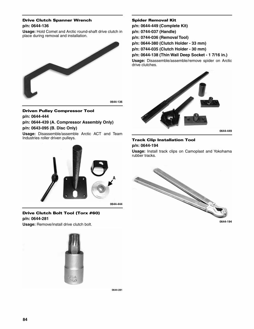
Drive Clutch Spanner Wrench
p/n: 0644-136Usage: Hold Comet and Arctic round-shaft drive clutch inplace during removal and installation.
0644-136
Driven Pulley Compressor Tool
p/n: 0644-444p/n: 0644-439 (A. Compressor Assembly Only)p/n: 0643-095 (B. Disc Only)Usage: Disassemble/assemble Arctic ACT and TeamIndustries roller driven pulleys.
0644-444
Drive Clutch Bolt Tool (Torx #60)
p/n: 0644-281Usage: Remove/install drive clutch bolt.
0644-281
Spider Removal Kit
p/n: 0644-449 (Complete Kit)p/n: 0744-037 (Handle)p/n: 0744-036 (Removal Tool)p/n: 0644-380 (Clutch Holder - 33 mm)p/n: 0744-035 (Clutch Holder - 30 mm)p/n: 0644-138 (Thin Wall Deep Socket - 1 7/16 in.)Usage: Disassemble/assemble/remove spider on Arcticdrive clutches.
0644-449
Track Clip Installation Tool
p/n: 0644-194Usage: Install track clips on Camoplast and Yokohamarubber tracks.
0644-194
84

Track Stud Hole Drill (7 mm)
p/n: 1639-629Usage: Drill 7 mm hole through rubber tracks for install-ing studs.
1639-629
Throttle Position Sensor (TPS) AdjustmentTool Kit
p/n: 3639-891 (Complete Set)p/n: 1686-436 (Harness Only)p/n: 0644-359 (Torx-Head Screwdriver - #25 Only)p/n: 0644-344 (Torx-Head Screwdriver - #30 Only)p/n: 0644-345 (Pin Gauge Only)Usage: Precisely adjust the throttle position sensor oncarbureted and EFI models.
3639-891
Idler Wheel Puller Kit
p/n: 0644-122 (Complete Kit - 6 in.)p/n: 0644-400 (Complete Kit - 8 in.)p/n: 0644-114 (A. Handle - 6 in.)p/n: 0644-401 (A. Handle - 8 in.)p/n: 0644-111 (B. Insertion Tool)p/n: 0644-120 (C. Pivot Plate)p/n: 0644-118 (D. Adapter Plate - Smaller I.D.)p/n: 0644-538 (D. Adapter Plate - Larger I.D.)p/n: 0623-310 (E. Cap Screw)p/n: 0644-119 (F. Puller Bolt) - 6 in. Kitp/n: 0644-432 (F. Puller Bolt) - 8 in. KitUsage: Remove/install skid frame idler wheels.
0644-122
Floating Piston Location Gauge
p/n: 0644-350Usage: Precisely locate and measure floating pistondepth without use of a calipers.
0644-350
85
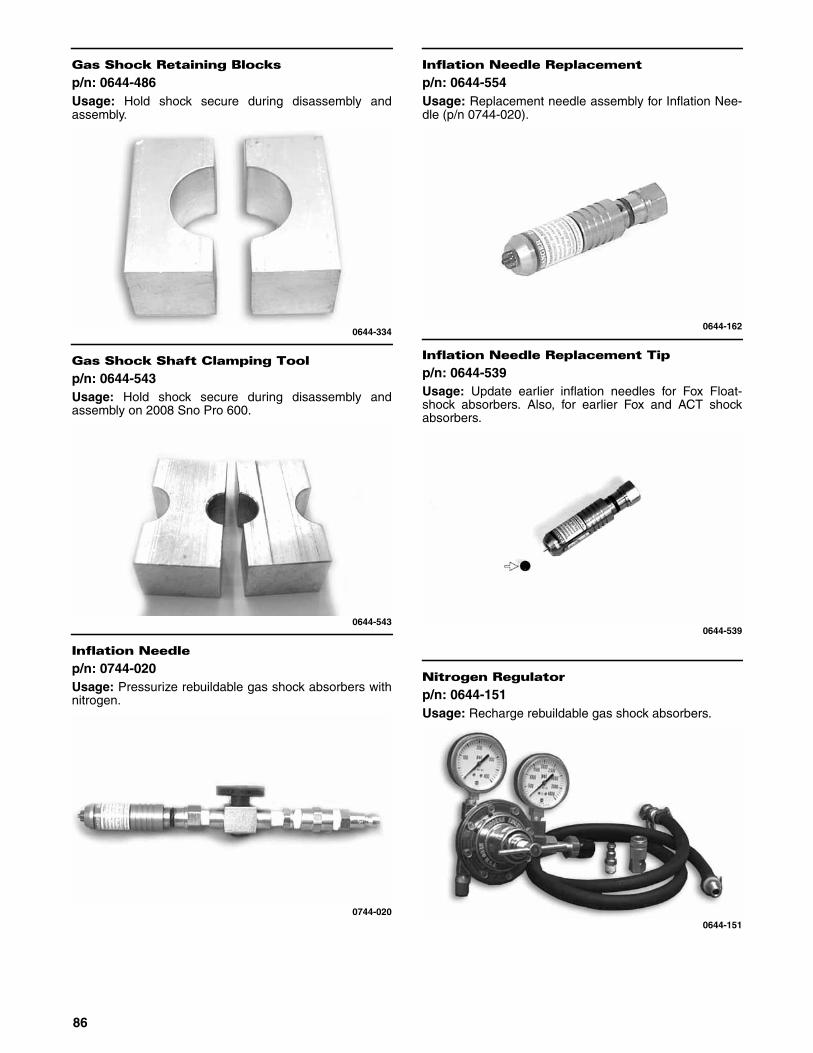
Gas Shock Retaining Blocks
p/n: 0644-486Usage: Hold shock secure during disassembly andassembly.
0644-334
Gas Shock Shaft Clamping Tool
p/n: 0644-543Usage: Hold shock secure during disassembly andassembly on 2008 Sno Pro 600.
0644-543
Inflation Needle
p/n: 0744-020Usage: Pressurize rebuildable gas shock absorbers withnitrogen.
0744-020
Inflation Needle Replacement
p/n: 0644-554Usage: Replacement needle assembly for Inflation Nee-dle (p/n 0744-020).
0644-162
Inflation Needle Replacement Tip
p/n: 0644-539Usage: Update earlier inflation needles for Fox Float-shock absorbers. Also, for earlier Fox and ACT shockabsorbers.
0644-539
Nitrogen Regulator
p/n: 0644-151Usage: Recharge rebuildable gas shock absorbers.
0644-151
86

Piston Location Tool
p/n: 0644-169Usage: Precisely locate the floating piston in the rebuild-able gas shock absorber.
0644-169
Axle Nut Spanner Wrench
p/n: 0644-454Usage: Adjust track alignment/tension (2005 440 SnoPro).
0644-454
Axle Nut Spanner Wrench
p/n: 0644-558Usage: Adjust track alignment/tension (2010-2011 SnoPro 500 and Sno Pro 600).
0644-558
Rear Suspension Spring Tool
p/n: 0144-311Usage: Install/remove rear suspension springs.
0144-311
Hex Bits (1/4 in. Hex Drive)
p/n: 0644-317 (5 mm)p/n: 0644-316 (6 mm)Usage: With Quick-Disconnect Coupler (p/n 0644-308),remove and install bolts and screws.
0644-316
Insert Holder (5/16 in.)
p/n: 0644-315Usage: With Torx Bit Insert (p/n 0644-314), remove andinstall torx-head screws.
0644-315
87

Phillips-Head Bits (1/4 in. Hex Drive)
p/n: 0644-319 (#2)p/n: 0644-318 (#3)Usage: With Quick-Disconnect Coupler (p/n 0644-308),remove and install Phillips-head screws.
0644-318
Quick-Disconnect Coupler
p/n: 0644-308Usage: Hold 1/4 in. hex drive Torx Bits (page 90), HexBits (page 87), and Phillips-Head Bits (page 88).
0644-308
Replacement Rivnuts
p/n: 0623-557 (1/4 x 20)p/n: 0623-582/627 (1/4 x 20)p/n: 0623-581 (5/16 x 18)p/n: 0623-699 (3/8 x 16)p/n: 0623-874 (8-32)p/n: 0623-529/779 (10-32)Usage: With Rivnut Tool (p/n 0644-232), replace rivnuts.
0623-557
Rivnut Tool
p/n: 0644-232Usage: Collapse and install rivnuts.
0644-232
Toggle-Switch Wrench
p/n: 0644-566Usage: Remove/install a toggle switch on 2010-2011 SnoPro 500.
0644-566
88

Rivnut Tool Insert Bit
p/n: 0644-233 (1/4 x 20)p/n: 0644-405 (10-32)p/n: 0644-430 (5/16 x 18)p/n: 0644-431 (3/8 x 16)Usage: With Rivnut Tool (p/n 0644-232) and Replace-ment Rivnuts, replace rivnuts.
0644-233
Vacuum Test Pump
p/n: 0644-131Usage: Check components for air leaks.
0644-131
EFI Fuel Pressure Test Kit
p/n: 0644-571Usage: Test fuel pressure.
0644-571
Oil Injection Usage Tool
p/n: 0644-007Usage: Measure exact amount of oil used by the oil injec-tion pump during a given time period.
0644-007
T-Handle Wrench
p/n: 0644-257 (8 mm)p/n: 0644-024 (10 mm)p/n: 0644-025 (12 mm)p/n: 0644-026 (14 mm)Usage: Remove and install nuts and bolts.
0644-257
T Wrench
p/n: 0644-021Usage: Drive 3/8 in. square-drive sockets.
0644-021
89
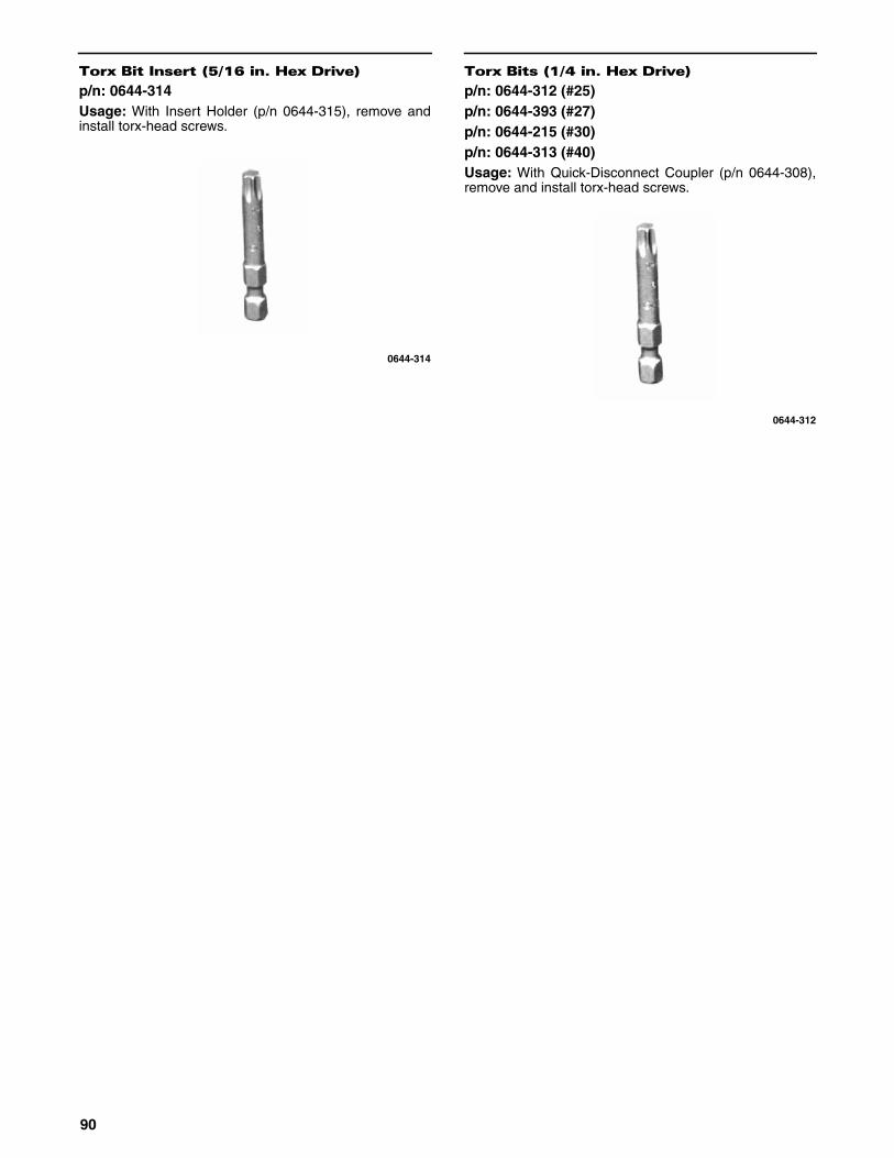
Torx Bit Insert (5/16 in. Hex Drive)
p/n: 0644-314Usage: With Insert Holder (p/n 0644-315), remove andinstall torx-head screws.
0644-314
Torx Bits (1/4 in. Hex Drive)
p/n: 0644-312 (#25)p/n: 0644-393 (#27)p/n: 0644-215 (#30)p/n: 0644-313 (#40)Usage: With Quick-Disconnect Coupler (p/n 0644-308),remove and install torx-head screws.
0644-312
90

NOTES
91

NOTES
92

®™Printed in U.S.A. Trademarks of Arctic Cat Inc., Thief River Falls, MN 56701 p/n 2258-802