operator’s handbook - avery...
TRANSCRIPT
TCADTP1OH Rev. AA 7/15© 2015 Avery Dennison Corp. All rights reserved.
Monarch® Products
OPERATOR’S HANDBOOK
TABLETOP PRINTER 1

ii Operator’s Handbook
Each product and program carries a respective written warranty, the only warranty on which the customer can rely. Avery Dennison Corp. reserves the r ight to make changes in the product, the programs, and their availabil ity at any time and without notice. Although Avery Dennison Corp. has made every effort to provide complete and accurate information in this manual, Avery Dennison Corp. shall not be liable for any omissions or inaccuracies. Any update wil l be incorporated in a later edit ion of this manual. 2015 Avery Dennison Corp. All rights reserved. No part of this publication may be reproduced, transmitted, stored in a retr ieval system, or translated into any language in any form by any means, without the prior written permission of Avery Dennison Corp. Trademarks Monarch and MPCL are trademarks of Avery Dennison Retail Information Services LLC. Avery Dennison® is a trademark of Avery Dennison Corp.

TOC-i
T A B L E O F C O N T E N T S GETTING STARTED ................................ ................................ ................................ .................. 1-1
Audience ................................ ................................ ................................ ............................. 1-1
Printer Overview ................................ ................................ ................................ .................. 1-1
Connecting the Power Cable ................................ ................................ ................................ . 1-3
Establishing Communications................................ ................................ ................................ 1-3
Using the Control Panel ................................ ................................ ................................ ........ 1-4
Selecting a Function ................................ ................................ ................................ ......... 1-4
Exiting a Function ................................ ................................ ................................ ............. 1-4
Sleep Delay ................................ ................................ ................................ ..................... 1-4
Selecting the Printer’s Language ................................ ................................ ....................... 1-5
Printing a Test Label ................................ ................................ ................................ ............ 1-5
LOADING SUPPLIES ................................ ................................ ................................ ................. 2-1
Using String Tags ................................ ................................ ................................ ............. 2-1
Loading Labels or Tags ................................ ................................ ................................ ........ 2-2
For String Tags ................................ ................................ ................................ ................ 2-4
For Fan-Fold Labels ................................ ................................ ................................ ......... 2-4
Loading Labels for Peel Mode (Optional) ................................ ................................ ............ 2-7
Loading Labels for Peel Mode with Liner Take-Up (Optional) ................................ .............. 2-13
Removing a Full Liner Take-Up Roll ................................ ................................ .................. 2-15
LOADING RIBBON ................................ ................................ ................................ .................... 3-1
About Ribbons ................................ ................................ ................................ .................. 3-1
PRINTING ................................ ................................ ................................ ................................ . 4-1
Printing ................................ ................................ ................................ ............................... 4-1
Pausing While Printing ................................ ................................ ................................ ......... 4-2
Canceling Printing................................ ................................ ................................ ................ 4-2
Repeating a Batch ................................ ................................ ................................ ............... 4-2
CARE & MAINTENANCE ................................ ................................ ................................ ............ 5-1
Clearing Label Jams................................ ................................ ................................ ............. 5-1
Cleaning ................................ ................................ ................................ ............................. 5-2
Replacing the Printhead ................................ ................................ ................................ ....... 5-4
TROUBLESHOOTING ................................ ................................ ................................ ................ 6-1
Adjusting the Print Quality ................................ ................................ ................................ .... 6-1
Setting the Print Contrast ................................ ................................ ................................ .. 6-1
Adjusting the Printhead Pressure Dials ................................ ................................ .............. 6-2
Troubleshooting ................................ ................................ ................................ ................... 6-3
Error Messages ................................ ................................ ................................ ................... 6-4

ii Operator’s Handbook
SPECIFICATIONS ................................ ................................ ................................ ..................... A-1
Printer ................................ ................................ ................................ ................................ A-1
Supplies (Media) ................................ ................................ ................................ .................. A-1
Ribbon ................................ ................................ ................................ ................................ A-2
Getting Started 1-1
G E T T I N G S T A R T E D The Avery Dennison® Monarch® Tabletop Printer 1 prints on thermal transfer (ribbon) and thermal direct labels or tags. The printer prints labels continuously (in one strip) or on-demand (one label at a time). You can print on aperture, die cut, black mark, or continuous (non-indexed) supplies.
This chapter explains how to:
♦ connect the power cord and communication cable.
♦ use the printer's control panel.
A power cord and ribbon take-up core (may already be on take-up reel) are included. Keep the box and packaging material in case the printer ever needs repair.
Note: Review the Safety Document included with your printer and the Regulatory information found on our Web site.
A u d i e n c e
This Operator's Handbook is for the person who prints and applies labels. For advanced printer setup (configuring the printer, changing RFID settings), refer to the System Administrator’s Guide.
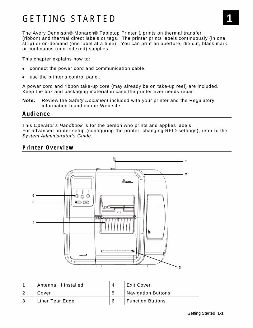
P r i n t e r O v e r v i e w
1 Antenna, if installed 4 Exit Cover
2 Cover 5 Navigation Buttons
3 Liner Tear Edge 6 Function Buttons
1
1
2
3
5
6
4
1-2 Operator's Handbook
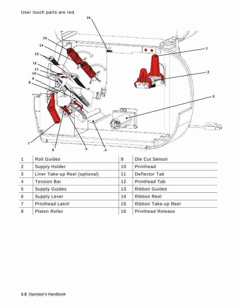
User touch parts are red.
1 Roll Guides 9 Die Cut Sensor
2 Supply Holder 10 Printhead
3 Liner Take-up Reel (optional) 11 Deflector Tab
4 Tension Bar 12 Printhead Tab
5 Supply Guides 13 Ribbon Guides
6 Supply Lever 14 Ribbon Reel
7 Printhead Latch 15 Ribbon Take-up Reel
8 Platen Roller 16 Printhead Release
1
2
3
4
7 5 6
8
11 10 9
12
13
14
15
16
Getting Started 1-3
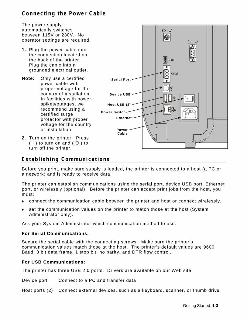
C o n n e c t i n g t h e P o w e r C a b l e
The power supply automatically switches between 115V or 230V. No operator settings are required.
1. Plug the power cable into the connection located on the back of the printer. Plug the cable into a grounded electrical outlet.
Note: Only use a certif ied power cable with proper voltage for the country of installation. In facilities with power spikes/outages, we recommend using a certif ied surge protector with proper voltage for the country of installation.
2. Turn on the printer. Press ( I ) to turn on and ( O ) to turn off the printer.
E s t a b l i s h i n g C o m m u n i c a t i o n s Before you print, make sure supply is loaded, the printer is connected to a host (a PC or a network) and is ready to receive data.
The printer can establish communications using the serial port, device USB port, Ethernet port, or wirelessly (optional). Before the printer can accept print jobs from the host, you must: ♦ connect the communication cable between the printer and host or connect wirelessly.
♦ set the communication values on the printer to match those at the host (System Administrator only).
Ask your System Administrator which communication method to use.
For Serial Communications:
Secure the serial cable with the connecting screws. Make sure the printer's communication values match those at the host. The printer’s default values are 9600 Baud, 8 bit data frame, 1 stop bit, no parity, and DTR flow control.
For USB Communications:
The printer has three USB 2.0 ports. Drivers are available on our Web site.
Device port Connect to a PC and transfer data
Host ports (2) Connect external devices, such as a keyboard, scanner, or thumb drive
Serial Port
Device USB
Host USB (2)
Power Switch
Ethernet
Power Cable

1-4 Operator's Handbook
MPCL READY
192.0.0.192
FEE D TLABE L M EN U
For Ethernet Communications:
If you are using Ethernet communications, you can monitor the status using the LEDs as shown:
Top LED: Blinking green
network activity/receiving data
Bottom LED: Orange a connection is present
U s i n g t h e C o n t r o l P a n e l The control panel has an LCD display and five buttons. The top three buttons are function buttons, which vary depending on the task shown above the button. The two bottom buttons are navigation buttons; use these to scroll through menus.
The LCD
♦ uses a red background when immediate attention (jam or error) is required. For more information see Chapter 6 "Diagnostics & Troubleshooting."
♦ uses a green background when the printer is active (printing or receiving data).
♦ uses a white background when viewing menu prompts, printer settings, button functions, etc.
Selecting a Function
Your System Administrator can access the MENU to configure the printer.
♦ Press MENU.
♦ Press or to see the menu options.
♦ Press SELECT when you see the menu option you need.
Exiting a Function
There are two ways to exit an option. Pressing BACK once returns to the previous menu and saves any changes. Pressing CANCEL exits to the previous menu; however, changes are not saved.
Sleep Delay When the printer is idle for a selected period of time, it goes into sleep mode to conserve power. Your System Administrator can adjust the Sleep Delay setting. The default setting is 60 minutes. The printer wakes from sleep mode when it receives a print job, a button is pressed, or the printhead is opened or closed.
Green LED
Orange LED

Getting Started 1-5
Selecting the Printer’s Language
To change the printer’s menu language:
1. Press MENU.
2. Press or until you see SETUP. Press SELECT.
3. Press or until you see LANGUAGE. Press CHANGE.
4. Press or until you see the language you need, then press SET.
5. Press BACK until you see “Ready,” then press SELECT.
P r i n t i n g a T e s t L a b e l Before you call Technical Support, print a test label.
1. From the Main Menu select TLABEL.
2. Press or to scroll through the test label options:
Printer Information MPCL Label
Contains generic information, including inch counts and printhead resolution.
Contains the printer’s MPCL packet configuration.
3. When you see the test label you need, press PRINT. Press BACK to return to the
previous menu without printing a test label.

1-6 Operator's Handbook
Loading Supplies 2-1
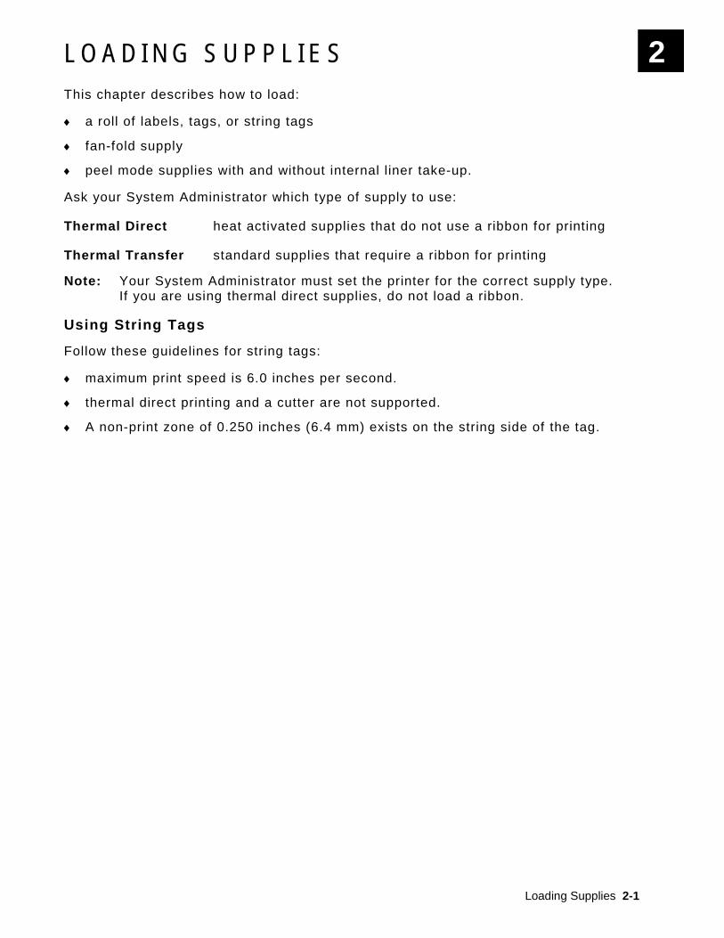
L O A D I N G S U P P L I E S This chapter describes how to load:
♦ a roll of labels, tags, or string tags
♦ fan-fold supply
♦ peel mode supplies with and without internal liner take-up.
Ask your System Administrator which type of supply to use:
Thermal Direct heat activated supplies that do not use a ribbon for printing
Thermal Transfer standard supplies that require a ribbon for printing
Note: Your System Administrator must set the printer for the correct supply type. If you are using thermal direct supplies, do not load a ribbon.
Using String Tags
Follow these guidelines for string tags:
♦ maximum print speed is 6.0 inches per second.
♦ thermal direct printing and a cutter are not supported.
♦ A non-print zone of 0.250 inches (6.4 mm) exists on the string side of the tag.
2

2-2 Operator's Handbook
L o a d i n g L a b e l s o r T a g s
1. Open the cover.
2. Turn the printhead latch to unlock the printhead.
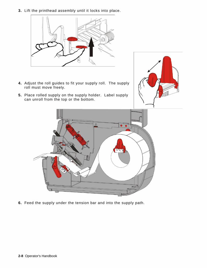
3. Lift the printhead assembly until it locks into place.

Loading Supplies 2-3
4. Adjust the roll guides to fit your supply roll. The supply roll must move freely.
5. Place rolled supply on the supply holder. Label supply can unroll from the top or the bottom; tag supply should unroll from the bottom only (tag rolls are wound face in).
6. Feed the supply under the tension bar and into the supply path.
2-4 Operator's Handbook
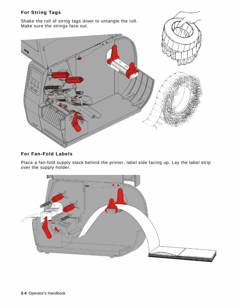
For String Tags
Shake the roll of string tags down to untangle the roll. Make sure the strings face out.
For Fan-Fold Labels
Place a fan-fold supply stack behind the printer, label side facing up. Lay the label strip over the supply holder.

Loading Supplies 2-5
7. Turn the supply lever to unlock the supply guides.
8. Feed the supply through the supply path so a few inches extend past the front of the printer. Tuck the supply under the nibs and die cut sensor.
9. Adjust the supply guides so they barely touch the supply. Turn the supply lever up to lock it in place.
10. Push the printhead release.
Supply Lever locked (up)
Supply Lever unlocked (down)
Supply Guide
Nibs
Die Cut Sensor
2-6 Operator's Handbook
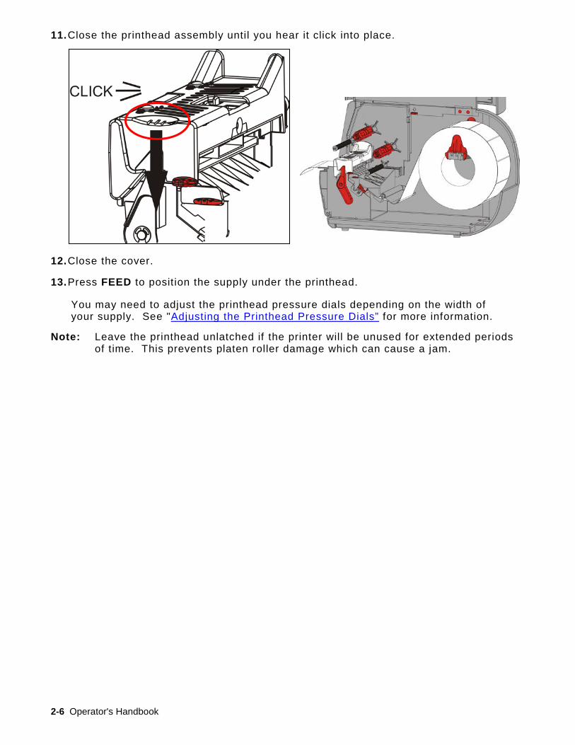
11. Close the printhead assembly until you hear it click into place.
12. Close the cover.
13. Press FEED to position the supply under the printhead.
You may need to adjust the printhead pressure dials depending on the width of your supply. See "Adjusting the Printhead Pressure Dials” for more information.
Note: Leave the printhead unlatched if the printer will be unused for extended periods of time. This prevents platen roller damage which can cause a jam.

Loading Supplies 2-7
Loading Labels for Peel Mode (Optional)
In peel mode, the printer separates the liner from the label. This is known as on-demand mode printing. The next label is not printed until the completed one is removed from the printer or when you press FEED. The display shows "Printing X of Y" until all labels print.
♦ minimum feed length is 1.5 inches.
♦ maximum speed is 8.0 inches per second.
♦ use non-perforated supplies.
Notes: Your System Administrator must set the printer for on-demand mode and the correct supply type.
1. Open the cover.
2. Turn the printhead latch to unlock the printhead.
2-8 Operator's Handbook
3. Lift the printhead assembly until it locks into place.
4. Adjust the roll guides to fit your supply roll. The supply roll must move freely.
5. Place rolled supply on the supply holder. Label supply can unroll from the top or the bottom.
6. Feed the supply under the tension bar and into the supply path.

Loading Supplies 2-9
7. Turn the supply lever to unlock the supply guides.
8. Feed the supply through the supply path so a few inches extend past the front of the printer. Tuck the supply under the nibs and die cut sensor.
9. Adjust the supply guides so they barely touch the supply. Turn the supply lever up to lock it in place.
Supply Guide
Nibs
Die Cut Sensor
Supply Lever locked (up)
Supply Lever unlocked (down)

2-10 Operator's Handbook
10. Press down on the exit cover tabs to open the exit cover on the front of the printer.
Loading Supplies 2-11
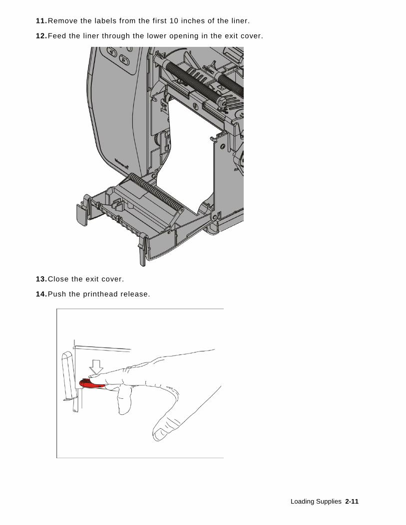
11. Remove the labels from the first 10 inches of the liner.
12. Feed the liner through the lower opening in the exit cover.
13. Close the exit cover.
14. Push the printhead release.

2-12 Operator's Handbook
15. Close the printhead assembly until you hear it click into place.
16. Close the cover.
17. Press FEED to position the supply under the printhead.
Note: To remove the liner, pull up across the tear edge.
Liner
Label

Loading Supplies 2-13
Loading Labels for Peel Mode with Liner Take-Up (Optional)
Use internal liner take-up with peel mode. Liner is collected on a take-up reel near the supply roll.
Note: Your System Administrator must set the printer to liner take-up (feed mode).
Remove the labels from the first 18 inches of the liner. Load supplies for peel mode, leaving at least 18 inches extending past the printhead.
1. Unlock and lift the printhead assembly until it locks into place.
2. Open the exit cover.
3. Feed the liner under the peel roller.
4. Remove the bail.
5. Wrap the liner around the take-up reel in a counter-clockwise direction.
Peel Roller
Bail
Take-up Reel

2-14 Operator's Handbook
6. Hold the liner while placing one end of the bail in a groove in the liner take-up reel.
Gently rotate the bail counter-clockwise until the other end snaps into the corresponding groove.
7. Gently slide the bail all the way onto the reel.
8. Turn the reel counter-clockwise to remove any slack in the liner.
9. Close the printhead assembly until you hear it click in to place.
10. Close the exit cover.
11. Close the cover.
12. Press FEED to position the supply under the printhead.
Rest the bail in the groove and rotate it counter-clockwise as shown.

Loading Supplies 2-15
Removing a Full Liner Take-Up Roll
The printer alerts you when the liner take-up reel is full. The liner take-up reel holds approximately half of a roll of liner.
Note: The liner can be removed before the take-up reel is full.
1. Open the cover.
2. Turn the printhead latch to unlock the printhead. Lift the printhead assembly until it locks into place.
3. Open the exit cover.
4. Gently pull the liner take-up bail off the liner take-up reel.
5. Use scissors to cut the liner in front of the take-up reel.
6. Remove the liner from the take-up reel.
7. Reload supply and continue printing.
Cut Liner Here

2-16 Operator's Handbook

Loading Ribbon 3-1
L O A D I N G R I B B O N This chapter describes how to load ribbon.
If you are using thermal direct supplies, do not load a ribbon.
Your System Administrator must set the printer to use a ribbon.
About Ribbons ♦ The ribbon cores only f it on the ribbon reels one way.
♦ Use your empty ribbon core as the take-up core.
♦ An extra take-up core is available by ordering part number 11796120 (2-inch), 11796130 (3-inch), or 11796140 (4-inch).
♦ Ribbons unwind from a clockwise or counter-clockwise direction.
1. Open the cover.
2. Turn the printhead latch to unlock the printhead.
3. Lift the printhead assembly until it locks into place.
3

3-2 Operator's Handbook
4. Push the deflector tab down.
5. Slide an empty ribbon core on the take-up reel as far as it will go.
6. Remove the new ribbon from the package. Do not wrinkle or crush the ribbon.
7. Slide the ribbon onto the back reel as far as it will go. Unwind a few inches of ribbon from the roll.
8. Carefully feed the ribbon around both ribbon guides and under the printhead.
9. Align the ribbon and make sure it is straight and centered throughout the path.
Take-up Core
Ribbon Guides
Printhead
Deflector Tab

Loading Ribbon 3-3
10. Use the adhesive on the ribbon leader to attach it to the take-up core. Make sure an empty take-up core is on the reel.
11. Rotate the take-up reel until the leader is past the printhead.
12. Remove any slack in the ribbon by turning the take-up reel until the ribbon is tight under the printhead.
13. Push the printhead release.
Printhead Release
3-4 Operator's Handbook
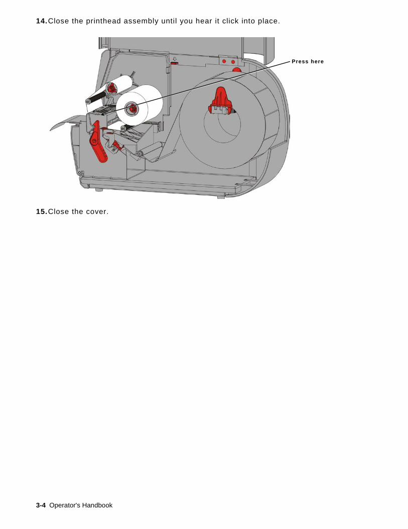
14. Close the printhead assembly until you hear it click into place.
15. Close the cover.
Press here

Printing 4-1
P R I N T I N G This chapter explains how to
♦ print, pause, cancel, and repeat a batch.
When the printer receives print data, batches begin printing automatically. Your System Administrator can use the Packet Reference Manual to create, store, and download the data necessary to print batches. Monarch® MPCL™ Toolbox Utilities are available on our Web site. You can also purchase label creation software.
P r i n t i n g
Before you print
♦ load supply
♦ connect the printer to a host (a PC or a network)
♦ make sure the printer is ready to receive data.
1. Turn on the printer – it is ready when you see:
2. Download a format and a batch.
3. The printer prints the batch (print job). Check the bar code print quality.
A bar code that is in spec has complete bars, clear spaces, and small alphanumeric characters look complete. An in spec bar code may not look as good as one that is too dark, but it has the highest scan rate. If the print is too dark/light or there are voids, see “Adjusting the Print Quality” for more information.
4
OR
MPCL
Ready
192.0.0.192
FEED TLABEL MENU
DATA ENTRY
Select Format
XXXXXXX
SELECT BACK
Dark IN SPEC Light

4-2 Operator's Handbook
P a u s i n g W h i l e P r i n t i n g 1. Press PAUSE to interrupt printing. The LCD is green.
2. Press ENTER to resume printing the current batch OR press or to display the Pause Menu options:
Select To Cancel Batch Cancel the currently printing batch. Cancel All Cancel all batches (jobs) in the print queue. Resume Continue printing the current batch. Restart Batch Reprint a paused batch from the beginning (using the original quantity).
C a n c e l i n g P r i n t i n g Press ESCAPE anytime while the batch is printing or press PAUSE, select Cancel Batch, and press ENTER.
R e p e a t i n g a B a t c h
Before you start printing a new batch, you can reprint the last batch. The batch can be either the last one you printed completely or one that you canceled after starting to print.
1. From the Main Menu, press or until you see
2. Press ENTER to reprint the last batch. The number increments until the entire batch is printed.
MAIN MENU
← Repeat Batch →
ENTER BACK
PAUSE MENU
← Resume →
ENTER BACK
Care & Maintenance 5-1
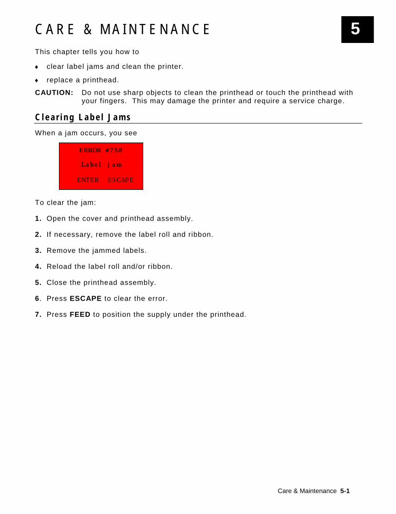
ERROR #758
Label jam
ENTER ESCAPE
C A R E & M A I N T E N A N C E This chapter tells you how to
♦ clear label jams and clean the printer.
♦ replace a printhead.
CAUTION: Do not use sharp objects to clean the printhead or touch the printhead with your f ingers. This may damage the printer and require a service charge.
C l e a r i n g L a b e l J a m s When a jam occurs, you see
To clear the jam:
1. Open the cover and printhead assembly.
2. If necessary, remove the label roll and ribbon.
3. Remove the jammed labels.
4. Reload the label roll and/or ribbon.
5. Close the printhead assembly.
6. Press ESCAPE to clear the error.
7. Press FEED to position the supply under the printhead.
5

5-2 Operator's Handbook
C l e a n i n g Clean the printhead, peel bar, sensor, and platen roller:
♦ when there is any adhesive build-up in the supply path.
♦ after printing approximately three rolls of thermal transfer/thermal direct supplies or after each ribbon.
♦ daily if your printer is in an excessively dirty, hot, or humid environment.
♦ if there are voids or streaking in the print as shown.
1. Turn off the printer, open the cover and printhead assembly.
2. Remove the supply roll and ribbon.
3. Press down on the exit cover tabs to open the exit cover on the front of the printer.
4. Spray the supply path and sensor with compressed air to remove dust and debris.
5. Use a cotton swab moistened with isopropyl alcohol to clean the printhead, peel bar, sensor, and platen roller when you see significant adhesive build-up or after clearing a jammed label.
Note: Use a printhead CLEAN STRIP (120350) if the printhead is extremely dirty or you see streaks on the supply.
Voids Streaks

Care & Maintenance 5-3
Turn the platen roller with your f inger to make sure it is clean all the way around.
6. Once the printer is dry, reload the ribbon and supply roll.
7. Close the exit cover by pushing firmly on it. Both latches click into place.
8. Close the printhead assembly and cover.
9. Turn on the printer.
10. Press FEED to position the supply under the printhead.
Supply Sensor
Die Cut Sensor
Platen Roller
5-4 Operator's Handbook
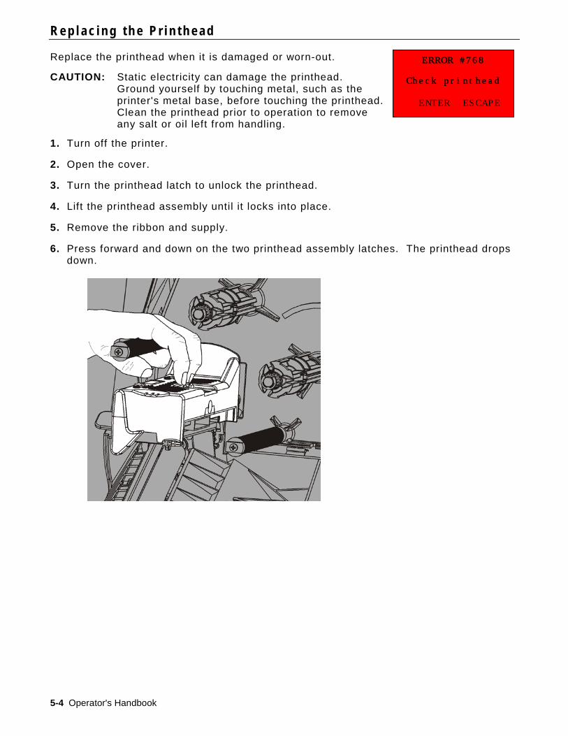
ERROR #768
Check printhead
ENTER ESCAPE
R e p l a c i n g t h e P r i n t h e a d
Replace the printhead when it is damaged or worn-out.
CAUTION: Static electricity can damage the printhead. Ground yourself by touching metal, such as the printer's metal base, before touching the printhead. Clean the printhead prior to operation to remove any salt or oil left from handling.
1. Turn off the printer.
2. Open the cover.
3. Turn the printhead latch to unlock the printhead.
4. Lift the printhead assembly until it locks into place.
5. Remove the ribbon and supply.
6. Press forward and down on the two printhead assembly latches. The printhead drops down.
Care & Maintenance 5-5
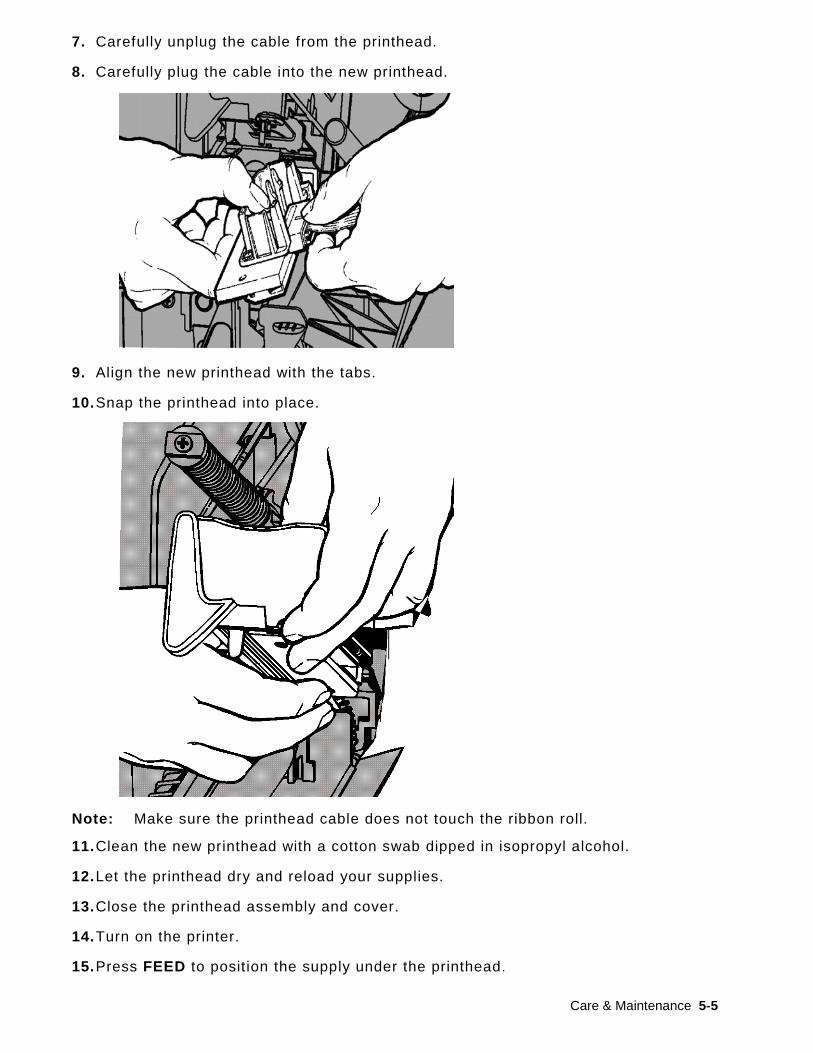
7. Carefully unplug the cable from the printhead.
8. Carefully plug the cable into the new printhead.
9. Align the new printhead with the tabs.
10. Snap the printhead into place.
Note: Make sure the printhead cable does not touch the ribbon roll.
11. Clean the new printhead with a cotton swab dipped in isopropyl alcohol.
12. Let the printhead dry and reload your supplies.
13. Close the printhead assembly and cover.
14. Turn on the printer.
15. Press FEED to position the supply under the printhead.

5-6 Operator's Handbook

Troubleshooting 6-1
T R O U B L E S H O O T I N G This chapter explains how to adjust print quality and contains basic troubleshooting information.
If you need to call Technical Support, print a test label f irst. See “Printing a Test Label” in Chapter 1 for more information.
A d j u s t i n g t h e P r i n t Q u a l i t y Many factors impact print quality: type of supplies, print speed, print contrast, and the type of printer application. The printer supports both thermal transfer and thermal direct supplies. The type of supply should match the printer’s application.
♦ Use premium supplies if you want to print at high speeds.
♦ Select the print speed based on desired throughput and print quality. If print quality is more important, reduce the print speed. A lower print speed increases the print quality of labels. If throughput is more important, increase the print speed.
♦ If the print quality is too light or too dark, adjust the print contrast or the printhead pressure dials.
Setting the Print Contrast Having the correct print contrast setting is important because it affects how well your bar codes scan and how long your printhead lasts.
To change the print contrast:
1. Press MENU.
2. Press or until you see SETUP. Press SELECT.
3. Press or until you see CONTRAST. Press SELECT.
4. Press CHANGE. The current setting is shown.
5. Press or to increase or decrease the contrast. Increasing the contrast setting darkens the print; decreasing the contrast setting lightens the print.
Note: Press the left function button to change the amount (adjusts to change by 1, 10, or 100).
6. When you see the contrast setting you need on the display, press SET to save.
7. Press BACK until you see “Ready,” then press SELECT.
6
SETUP
← Contrast →
[-699/699] 0
1 SET CANCEL
SETUP
← Contrast →
0
CHANGE BACK

6-2 Operator's Handbook
Adjusting the Printhead Pressure Dials
Two dials are located on either edge of the printhead assembly. Use a coin or f lathead screwdriver to adjust the dials based on the width of your supply. The “out of the box” setting (default) is least pressure, which provides optimal printing in most cases.
If you see smudging, ribbon wrinkling, or poor print quality, adjust the printhead pressure dials.
Note: Both dials must be set to the same position.
Each dial has four settings:
♦ Least pressure
♦ Light pressure
♦ Medium pressure
♦ Most pressure
Use the following guidelines to adjust the printhead pressure. Check print quality and repeat if necessary.
Supply Width Dial Settings
Wide supply (> 2 inches)
Increase both dials one step.
Narrow supply (≤ 2 inches)
Decrease both dials one step.
If print quality does not improve, Contact Technical Support.
Knob is set to least pressure adjustment (knobs are up).
Most Pressure
Least Pressure
Troubleshooting 6-3
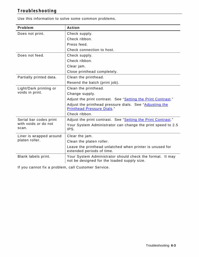
T r o u b l e s h o o t i n g Use this information to solve some common problems. Problem Action Does not print. Check supply.
Check ribbon. Press feed. Check connection to host.
Does not feed. Check supply. Check ribbon. Clear jam. Close printhead completely.
Partially printed data. Clean the printhead. Resend the batch (print job).
Light/Dark printing or voids in print.
Clean the printhead. Change supply. Adjust the print contrast. See “Setting the Print Contrast.” Adjust the printhead pressure dials. See “Adjusting the Printhead Pressure Dials.” Check ribbon.
Serial bar codes print with voids or do not scan.
Adjust the print contrast. See “Setting the Print Contrast.” Your System Administrator can change the print speed to 2.5 IPS.
Liner is wrapped around platen roller.
Clear the jam. Clean the platen roller. Leave the printhead unlatched when printer is unused for extended periods of time.
Blank labels print. Your System Administrator should check the format. It may not be designed for the loaded supply size.
If you cannot f ix a problem, call Customer Service.

6-4 Operator's Handbook
ERROR #756
Load supplies
ENTER ESCAPE
E r r o r M e s s a g e s
Contact your System Administrator if you cannot clear an error or you see an error not listed below.
Many of these errors require action by your System Administrator.
Error Action 411 Make sure the printer’s communication values match those at the host.
614 Check for invalid characters in the data packets.
616 A bar code on the label did not print. Check with your System Administrator.
703 704
Check/load supply. The printer’s supply type must match the loaded supply. For example, the printer is set for die cut supply, but black mark supply is loaded.
741 743
Check supply loading and the settings in the Monarch® RFID Printer Setup Utility.
750 Turn off the printer to let the printhead cool down.
751 752 753 756 757
Load supply. Press ENTER to continue printing.
Clean sensor.
754 Check/load ribbon. Press ENTER to continue printing.
755 Close the printhead to continue.
758 Check for a label jam, clear the supply path, or reload supplies. This error may occur if you remove a label too quickly in the on-demand mode.
763 Waiting to dispense label. Press FEED.
765 768
Check/replace the printhead. Press ESCAPE to continue.
785 786
Remove the liner from the take-up core. Reload supply for liner take-up. Press ESCAPE to continue.
Note: If the above actions do not clear the error, turn off the printer, wait several
seconds and then turn on the printer.

Specifications A-1
S P E C I F I C A T I O N S P r i n t e r
Height: 13.8 inches (351.1 mm)
Width: 11.6 inches (293.5 mm)
Depth: 21.7 inches (550.8 mm)
Weight: 33 lb. (15 kg)
Shipping Weight: 38 lb. (17.3 kg)
Power Source: 100-240 VAC, 50-60Hz
Operating Limits: Thermal Transfer (ribbon): 40° to 95°F (4° to 35°C) Thermal Direct: 40° to 104°F (4º to 40°C) Storage: 15°F to 120°F (-10°C to 49°C) Humidity: 5% to 90% non-condensing
Printhead: Thermal at 4.09 inches (103 mm) wide 203 dpi (8.0 dots per mm)
Printing Method: Thermal Transfer (ribbon) or Thermal Direct
Print Speed: 2.5 ips (64 mm) default for all serial bar codes, 4.0 ips (102 mm), 6.0 ips (152 mm), 8.0 ips (203mm), 10.0 ips (254 mm), or 12.0 ips (305 mm)
Max Print Area: 4.09 inches x 20.0 inches (102 mm x 508 mm)
S u p p l i e s ( M e d i a ) Supply Widths: 0.75 inches (19 mm) minimum for labels and tags
4.32 inches (108 mm) maximum for labels and tags
Supply Lengths: 0.32 inch (8 mm) minimum for non-peel mode 1.50 inches (38 mm) for peel mode
17.5 inches (444.5 mm) maximum for labels and tags 20 inches (508 mm) maximum
0.75 inch (19 mm) minimum for tags 1.2 inches (30 mm) minimum for cutting tags
Total Thickness: 5 to 14 mils
Max. Roll Diameter: 9.375 inches (238 mm)
Supply Core: 3.0 inches (76 mm) minimum 4.0 inches (101.6 mm) maximum
For string tag specifications, refer to the System Administrator’s Guide.
A
A-2 Operator's Handbook
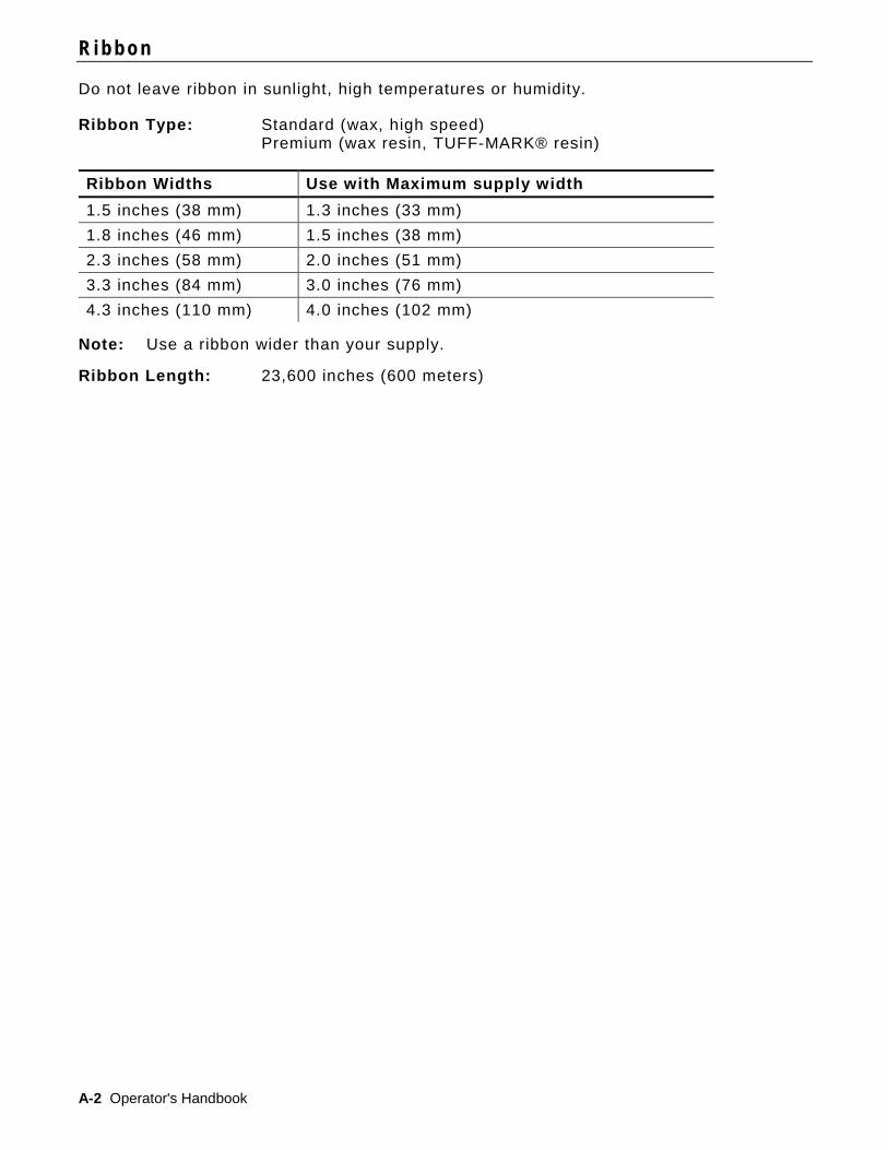
R i b b o n
Do not leave ribbon in sunlight, high temperatures or humidity.
Ribbon Type: Standard (wax, high speed) Premium (wax resin, TUFF-MARK® resin)
Ribbon Widths Use with Maximum supply width 1.5 inches (38 mm) 1.3 inches (33 mm) 1.8 inches (46 mm) 1.5 inches (38 mm) 2.3 inches (58 mm) 2.0 inches (51 mm) 3.3 inches (84 mm) 3.0 inches (76 mm) 4.3 inches (110 mm) 4.0 inches (102 mm)
Note: Use a ribbon wider than your supply.
Ribbon Length: 23,600 inches (600 meters)


Avery Dennison PrinterSystems Division,170 Monarch Lane,Miamisburg, OH 45342
Printer Documentation
http://rbis.averydennison.com/ADTP1
USCA