operator's manual for ah-64a (apache) combat mission …
TRANSCRIPT
TM 55-6930-214-10
TECHNICAL MANUAL
OPERATOR'S MANUAL
FOR
AH-64A (APACHE) COMBAT MISSION SIMULATOR
“Approved for public release; distribution is unlimited.”
HEADQUARTERS, DEPARTMENT OF THE ARMY15 MARCH 1988


CHANGE
NO. 2
TM 55-6930-214-10C 2
HEADQUARTERSDEPARTMENT OF THE ARMY
WASHINGTON, D.C., 30 April 1992
Operator’s Manual
f o r
AH-64A (Apache) Combat Mission Simulator
TM 55-6930-214-10, 15 March 1988, is changed as follows:
1. Remove and inse r t pages as ind ica ted be low. New or changed t ex t ma te r i a li s i n d i c a t e d b y a v e r t i c a l b a r i n t h e m a r g i n . A n i l l u s t r a t i o n c h a n g e i s i n d i c a t e dby a min ia tu re po in t ing hand .
Remove pages I n s e r t p a g e s
A through C/Dc / di t h r o u g h x i / x i il - l / l - 22 - l t h rough 2 -62-9 through 2-162-17 through 2-282-31/2-323-1 and 3-24 - l / 4 - 25 - l t h r o u g h 5 - 5 / 5 - 67- l t h rough 7 -107-15 through 7-50- - - -7-51 through 7-56- - - -7-57 through 7-90- - - -7-91 through 7-114- - - -7-115 and 7-116- - - - 7-117 and 7-1187-121 through 7-140- - - -7-141 and 7-1427-145 through 7-173/7-1747-229 and 7-2307-233 and 7-2347-237 and 7-2387-249 and 7-2507-259 through 7-262- - - - 7-263 and 7-2648- l t h rough 8 -4
- - - - -
c / di t h r o u g h x i / x i il - 1 / 1 - 22- l t h rough 2 -42-9 th rough 2 -15 /2 -162-17 through 2-282-31/2-323- l and 3 -24 - l / 4 - 25- l t h rough 5 -5 /5 -67- l t h rough 7 -107-15 through 7-507-50 .1 /7 -50 .27-51 through 7-567-56 .1 and 7 -56 .27-57 through 7-907-90 .1 th rough 7 -90 .67-91 through 7-1147-114 .1 /7 -114 .27-115 and 7-1167-116.1 and 7-116.27-117 and 7-1187-121 through 7-1407-140.1 through 7-140.47-141 and 7-1427-145 through 7-173/7-1747-229 and 7-2307-233 and 7-2347-237 and 7-2387-249 and 7-2507-259 through 7-2627-262 .1 /7 -262 .27-263 and 7-2648- l t h rough 8 -4

TM 55-6930-214-10C 2
Remove pages I n s e r t p a g e s
Glossary 3 and Glossary 4 Glossary 3 and Glossary 4Index 1 through Index 7/8 Index 1 through Index 7/8
2 . R e t a i n t h i s s h e e t i n f r o n t o f m a n u a l f o r r e f e r e n c e p u r p o s e s .
By Order of the Secretary of the Army:
Official:
MILTON H. HAMILTON
GORDON R. SULLIVANGeneral, United States Army
Chief of Staff
Administrative Assistant to theSecretary of the Army
01735
DISTRIBUTION:To be distr ibuted in accordance with DA Form 12-31 -10 and CL maintenance
requirements for TM 55-6930-214-10.
TM 55-6930-214-10C 1
CHANGE
No. 1
HEADQUARTERSDEPARTMENT OF THE ARMY
W A S H I N G T O N, D.C., 17 January 1989
Operator 's Manual
f o r
AH-64A (Apache) Combat Mission Simulator
TM 55-6930-214-10, 15 March 1988, is changed as follows:
1. Remove and insert pages as indicated below. New or changed test materiali s i n d i c a t e d b y a v e r t i c a l b a r i n t h e m a r g i n . A n i l l u s t r a t i o n c h a n g e i s i n d i c a t e dby a min ia tu re po in t ing hand .
Remove pages: I n s e r t p a g e s :
A and B- - -v i i a n d v i i i2 - l and 2 -22-7 through 2-102-19 through 2-285-1 th rough 5 -5 /5 -66 - l / 6 - 27- l and 7 -27-5 through 7-87-17 and 7-187-29 through 7-327-37 through 7-507-57 through 7-607-69 through 7-727-77 and 7-787-91 and 7-927-99 through 7-1027-105 through 7-1107-113 and 7-1147-127 and 7-1287-131 and 7-1327-135 through 7-1387-141 and 7-1427-153 and 7-1547-157 through 7-1647-175 through 7-180- - -7-181 through 7-276Index 5 and Index 6
A and BC/Dv i i a n d v i i i2-1 and 2-22-7 through 2-102-19 through 2-285- l t h rough 5 -5 /5 -66 - l / 6 - 27- l and 7 -27-5 through 7-87-17 and 7-187-29 through 7-327-37 through 7-507-57 through 7-607-69 through 7-727-77 and 7-787-91 and 7-927-99 through 7-1027-105 through 7-1107-113 and 7-1147-127 and 7-1287-131 and 7-1327-135 through 7-1387-141 and 7-1427-153 and 7-1547-157 through 7-1647-175 through 7-1807-180.1 through 7-180.3/7-180.47-181 through 7-276Index 5 and Index 6
2. Re ta in these shee t s in f ron t o f manua l fo r r e fe rence purposes .

TM 55-6930-214-10C 1
By Order of the Secretary of the Army:
Official:
CARL E. VUONO,General, United States Army
Chief of Staff
WILLIAM J. MEEHAN IIBrigadier General, United States Army
The Adjutant General
DISTRIBUTION:To be distr ibuted in accordance with DA Form 12-31 (-10 and CL Maintenance
Requirements for AH-64A Helicopter, Attack, (Apache).
TM 55-6930-214-10
WARNING
HIGH VOLTAGE
is used in the operation of this equipment.
DEATH ON CONTACT
or severe in jury may resu l t i f personne l fa i l to observe sa fe typrecautions.
Learn the areas containing high voltage in each piece of equipment.
Under no circumstances should operation of this device be undertakenwhen cabinets and/or protective covers are removed or open.
WARNING
Motion system operation requires thatSEAT BELTS BE USED AT ALL TIMES.
In the case of runaway motion, immediatelyactivate EMERGENCY STOP switch.
DEATH
or severe in jury may resu l t i f personne l fa i l to observe sa fe typrecautions.
WARNING
EMERGENCY STOP
Controls are located at each trainee station control panel and at eachins tructor /operator conso le . Depressing this switch shuts down the
entire simulator complex.
DEATH
or severe in jury may resu l t i f personne l fa i l to observe sa fe typrecautions.
a
TM 55-6930-214-10
WARNING
Sensors that detect heat, lack of airflow, and unsafe mechanicalconditions are provided. UNDER NO CIRCUMSTANCES SHOULD THE MISSION
SIMULATOR BE OPERATED WITH A SAFETY INTERLOCK BYPASSED.
DEATH
or severe injury may result if personnel fail to observe safety pre-caut ions .
WARNING
FIRE
Should fire develop, activate EMERGENCY STOPand ex i t cockpi t . DO NOT USE FIRE EXTINGUISHER IN CONFINED COCKPIT.
DEATH
or severe injury may result if personnel fail to observe safetyprecautions.
WARNING
BOARDING RAMP
May fail to deploy during a power failure.Caution should be exercised when exiting simulator.
DEATH
or severe in jury may resu l t i f personne l fa i l to observe sa fe typrecautions.
WARNING
Releasing trainer from freeze conditionwith incorrect rotor rpm may cause motion surges.
D E A T H
or severe in jury may resu l t i f personne l fa i l to observe sa fe typrecautions.
b
TM 55-6930-214-10
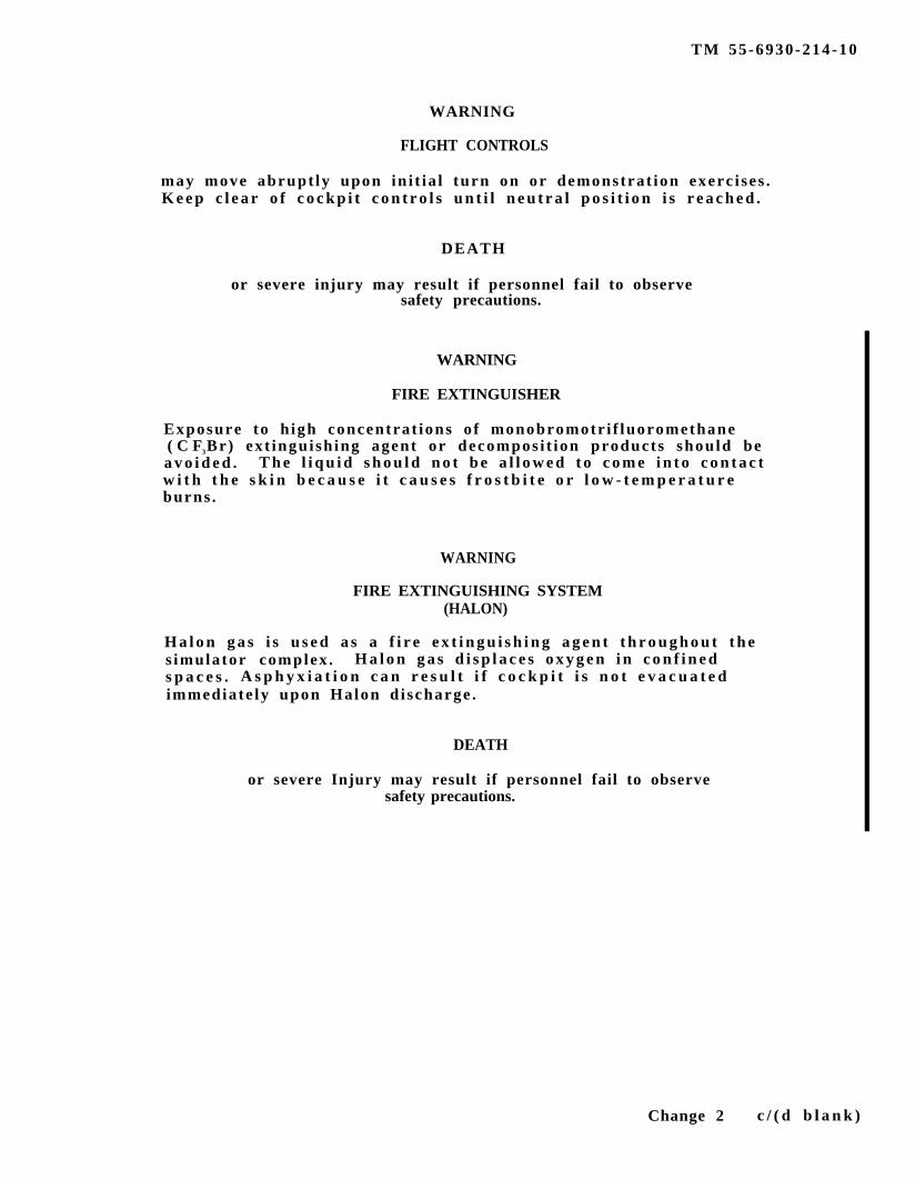
WARNING
FLIGHT CONTROLS
may move abrupt ly upon in i t ia l turn on or demonstrat ion exerc i ses .K e e p c l e a r o f c o c k p i t c o n t r o l s u n t i l n e u t r a l p o s i t i o n i s r e a c h e d .
DEATH
or severe injury may result if personnel fail to observesafety precautions.
WARNING
FIRE EXTINGUISHER
Exposure to h igh concentrat ions o f monobromotr i f luoromethane( C F3Br) ext inguish ing agent or decompos i t ion products should bea v o i d e d . T h e l i q u i d s h o u l d n o t b e a l l o w e d t o c o m e i n t o c o n t a c tw i t h t h e s k i n b e c a u s e i t c a u s e s f r o s t b i t e o r l o w - t e m p e r a t u r eburns .
WARNING
FIRE EXTINGUISHING SYSTEM(HALON)
H a l o n g a s i s u s e d a s a f i r e e x t i n g u i s h i n g a g e n t t h r o u g h o u t t h es imulator complex . H a l o n g a s d i s p l a c e s o x y g e n i n c o n f i n e ds p a c e s . A s p h y x i a t i o n c a n r e s u l t i f c o c k p i t i s n o t e v a c u a t e dimmediate ly upon Halon d i scharge .
DEATH
or severe Injury may result if personnel fail to observesafety precautions.
Change 2 c / ( d b l a n k )

TM 55-6930-214-10
INSERT LATEST CHANGED PAGES. DESTROY SUPERSEDED PAGES.
LIST OF EFFECTIVE PAGES
NOTE : T h e p o r t i o n o f t h e t e x t a f f e c t e d b y t h e c h a n g e s i s i n d i c a t e d b y av e r t i c a l l i n e i n t h e o u t e r m a r g i n s o f t h e p a g e . Changes toi l l u s t r a t i o n s a r e i n d i c a t e d b y m i n i a t u r e p o i n t i n g h a n d s . Changesto wi r ing d iag rams a re ind ica ted by change l egends .
Da tes o f i s sue fo r o r ig ina l and changed pages a re :
O r i g i n a l . . . . . . 0 . . . . . . . . 15 March 88C h a n g e . . . . . . . . 1 . . . . . . . . 17 Jan 89
Page *Change Page *Change Page *ChangeNo. No. No. No. No. No.
a - c . . . . . . . . . . . . . . .d Blank
0. . . . . . . . . . . . . 0
T i t l e . . . . . . . . . . . . . . . 1A - B . . . . . . . . . . . . . . . 1C . . . . . . . . . . . . . . . . . . . 1D Blank . . . . . . . . . . . . . 1Record of changes . . . 1Blank . . . . . . . . . . . . . . . 0i - v i i . . . . . . . . . . . . . 0v i i i . . . . . . . . . . . . . . . . 1ix - xi . . . . . . . . . . . . . 0x i i B lank . . . . . . . . . . . 0l - l . . . . . . . . . . . . . . . . . 0l-2 Blank . . . . . . . . . . . 02 - l . . . . . . . . . . . . . . . . . 12 -2 - 2 -6 . . . . . . . . . . . 02-7 . . . . . . . . . . . . . . . . . 12-8 . . . . . . . . . . . . . . . . . 02-9 . . . . . . . . . . . . . . . . . 12 -10 - 2 -19 . . . . . . . . . 02-20 - 2-21 . . . . . . . . . 12-22 . . . . . . . . . . . . . . . . 02-23 . . . . . . . . . . . . . . . . 12-24 - 2-25 . . . . . . . . . 02 -26 - 2 -27 . . . . . . . . . 12-28 - 2-31 . . . . . . . . . 02-32 Blank . . . . . . . . . . 03 - l - 3 - 2 . . . . . . . . . . . 04 - l . . . . . . . . . . . . . . . . . 04-2 Blank . . . . . . . . . . . 05 - l . . . . . . . . . . . . . . . . . 05-2 . . . . . . . . . . . . . . . . . 15-3 . . . . . . . . . . . . . . . . . 05 -4 - 5 -5 . . . . . . . . . . . 15-6 Blank . . . . . . . . . . . 0
6-1 . . . . . . . . . . . . . . . . . 16-2 Blank . . . . . . . . . . . 07 - l . . . . . . . . . . . . . . . . . 17 - 2 - 7 - 5 . . . . . . . . . . . 07 - 6 - 7 - 8 . . . . . . . . . . . 17 -9 - 7 -16 . . . . . . . . . . 07-17 . . . . . . . . . . . . . . . . 17 -18 - 7 -28 . . . . . . . . . 07 -29 - 7 -30 . . . . . . . . . 17-31 . . . . . . . . . . . . . . . . 07-32 . . . . . . . . . . . . . . . . 17 -33 - 7 -37 . . . . . . . . . 07 -38 - 7 -40 . . . . . . . . . 17-41 . . . . . . . . . . . . . . . . 07-42 . . . . . . . . . . . . . . . . 17-43 . . . . . . . . . . . . . . . . 17-44 . . . . . . . . . . . . . . . . 07 -45 - 7 -50 . . . . . . . . . 17 -51 - 7 -56 . . . . . . . . . 07-57 . . . . . . . . . . . . . . . . 17-58 . . . . . . . . . . . . . . . . 07-59 . . . . . . . . . . . . . . . . 17-60 - 7 -68 . . . . . . . . . 07-69 . . . . . . . . . . . . . . . . 17-70 - 7-71 . . . . . . . . . 07-72 . . . . . . . . . . . . . . . . 17 -73 - 7 -76 . . . . . . . . . 07-77 . . . . . . . . . . . . . . . . 17 -78 - 7 -90 . . . . . . . . . 07-91 . . . . . . . . . . . . . . . . 17 -92 - 7 -99 . . . . . . . . . 07-100 . . . . . . . . . . . . . . . 17-101 . . . . . . . . . . . . . . . 07-102 . . . . . . . . . . . . . . . 1
*Zero in th i s co lumn ind ica te s an o r ig ina l page .
7-103 - 7-104 . . . . . . . 07-105 - 7-107 . . . . . . . 17-108 - 7-109 . . . . . . . 07-110 . . . . . . . . . . . . . . . 17-111 - 7-113 . . . . . . . 07-114 . . . . . . . . . . . . . . . 17-115 - 7-126 . . . . . . . 07-127 . . . . . . . . . . . . . . . 17-128 - 7-130 . . . . . . . 07-131 - 7 -132 . . . . . . . 17-133 - 7-135 . . . . . . . 07-136 - 7-137 . . . . . . . 17-138 - 7-140 . . . . . . . 07-141 . . . . . . . . . . . . . . . 17-142 - 7-153 . . . . . . . 07-154 . . . . . . . . . . . . . . . 17-155 - 7-156 . . . . . . . 07-157 - 7-159 . . . . . . . 17-160 . . . . . . . . . . . . . . . 07-161 . . . . . . . . . . . . . . . 17-162 . . . . . . . . . . . . . . . 07-163 . . . . . . . . . . . . . . . 17-164 - 7-173 . . . . . . . 07-174 Blank . . . . . . . . . 07-175 . . . . . . . . . . . . . . . 07-176 - 7-180.3 . . . . . 17-180.4 Blank . . . . . . . 17-181 - 7-282 . . . . . . . 18 - l - 8 - 4 . . . . . . . . . . . 0Glossa ry 1 -
Glossa ry 5 . . . . . . . . 0Glossary 6 Blank . . . . 0Index 1 - Index 4 . . . 0Index 5 - Index 6 . . . 1
Change 1 A

TM 55-6930-214-10
LIST OF EFFECTIVE PAGES - CONTINUED
Page *Change Page *Change PageNo. No. No. No. No.
Index 7 . . . . . . . . . . . . . 0Index 8 Blank . . . . . . . 0
*ChangeNo.
*Zero in th i s co lumn ind ica te s an o r ig ina l page .
B Change 1

TM 55-6930-214-10
RECORD OF CHANGES
CHANGE ENTEREDNO. DATE TITLE OR BRIEF DESCRIPTION BY
1 17 JANUARY 1989 INCORPORATION OF CUSTOMER SINGER - LINKCOMMENTS TO EXISTING MANUAL
Change 1 C/(D blank)

TM 55-6930-214-10
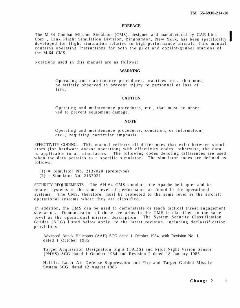
PREFACE
The M-64 Combat Mission Simulator (CMS), designed and manufactured by CAR-LinkCorp. , L ink P l igh t S imula t ion Div i s ion , B inghamton , New York , has been spec i f i ca l lyd e v e l o p e d f o r f l i g h t s i m u l a t i o n r e l a t i v e t o h i g h - p e r f o r m a n c e a i r c r a f t . T h i s m a n u a lc o n t a i n s o p e r a t i n g I n s t r u c t i o n s f o r b o t h t h e p i l o t a n d c o p i l o t / g u n n e r s t a t i o n s o fthe M-64 CMS.
Nota t ions used in th i s manua l a re a s fo l lows :
WARNING
O p e r a t i n g a n d m a i n t e n a n c e p r o c e d u r e s , p r a c t i c e s , e t c . , t h a t m u s tb e s t r i c t l y o b s e r v e d t o p r e v e n t i n j u r y t o p e r s o n n e l o r l o s s o fl i f e .
CAUTION
Opera t ing and main tenance p rocedures , e t c . , t ha t mus t be obse r -ved to prevent equipment damage.
NOTE
Opera t ing and main tenance p rocedures , cond i t ion , o r In fo rmat ion ,e t c . , r e q u i r i n g p a r t i c u l a r e m p h a s i s .
EFFECTIVITY CODING. T h i s m a n u a l r e f l e c t s a l l d i f f e r e n c e s t h a t e x i s t b e t w e e n s i m u l -a t o r s ( f o r h a r d w a r e a n d / o r o p e r a t i o n ) w i t h e f f e c t i v i t y c o d e s ; o t h e r w i s e , t h e d a t ai s a p p l i c a b l e t o a l l s i m u l a t o r s . The fo l lowing codes deno t ing d i f fe rences a re usedw h e n t h e d a t a p e r t a i n s t o a s p e c i f i c s i m u l a t o r . The s imula to r codes a re de f ined asfo l lows :
(1) = Simulator No. 2137020 (prototype)(2) = Simulator No. 2137021
SECURITY REQUIREMENTS. The AH-64 CMS simulates the Apache helicopter and i tsr e l a t ed sys tems to the same l eve l o f pe r fo rmance as found in the opera t iona lsystems. The CMS, the re fo re , mus t be p ro tec ted to the same leve l a s the a i rc ra f to p e r a t i o n a l s y s t e m s w h e r e t h e y a r e c l a s s i f i e d .
In add i t ion , the CMS can be used to demons t ra te o r t each t ac t i ca l th rea t engagements c e n a r i o s . Demons t ra t ion o f these scenar ios in the CMS i s c l a s s i f i ed to the samel e v e l a s t h e o p e r a t i o n a l m i s s i o n d e s c r i p t i o n . The Sys tem Secur i ty C lass i f i ca t ionG u i d e s ( S C G ) l i s t e d b e l o w a p p l y , t o t h e l a t e s t r e v i s i o n , i n c l u d i n g d e c l a s s i f i c a t i o np r o v i s i o n s :
Advanced Attack Helicopter (AAH) SCG dated 1 October 1984, with Revision No. 1,dated 1 October 1985
Targe t Acqu i s i t ion Des igna t ion S igh t (TADS) and P i lo t Nigh t Vis ion Sensor(PNVS) SCG dated 1 October 1984 and Revision 2 dated 18 January 1985
Hel l f i r e Lase r Ai r Defense Suppress ion and F i re and Targe t Guided Miss i l eSystem SCG, dated 12 August 1985
C h a n g e 2 i
TM 55-6930-214-10
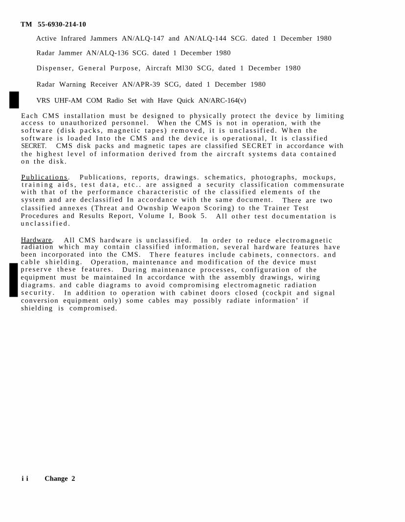
Active Infrared Jammers AN/ALQ-147 and AN/ALQ-144 SCG. dated 1 December 1980
Radar Jammer AN/ALQ-136 SCG. dated 1 December 1980
Dispenser , Genera l Purpose , Aircraft Ml30 SCG, dated 1 December 1980
Radar Warning Receiver AN/APR-39 SCG, dated 1 December 1980
VRS UHF-AM COM Radio Set with Have Quick AN/ARC-164(v)
Each CMS ins t a l l a t ion mus t be des igned to phys ica l ly p ro tec t t he dev ice by l imi t ingaccess to unau thor i zed pe r sonne l . When the CMS is not in operat ion, with thes o f t w a r e ( d i s k p a c k s , m a g n e t i c t a p e s ) r e m o v e d , i t i s u n c l a s s i f i e d . W h e n t h es o f t w a r e i s l o a d e d I n t o t h e C M S a n d t h e d e v i c e i s o p e r a t i o n a l , I t i s c l a s s i f i e dSECRET. CMS disk packs and magnetic tapes are classif ied SECRET in accordance witht h e h i g h e s t l e v e l o f i n f o r m a t i o n d e r i v e d f r o m t h e a i r c r a f t s y s t e m s d a t a c o n t a i n e do n t h e d i s k .
P u b l i c a t i o n s . Pub l i ca t ions , r epor t s , d rawings . schemat ic s , pho tographs , mockups ,t r a i n i n g a i d s , t e s t d a t a , e t c . . a re a s s igned a secur i ty c l a s s i f i ca t ion commensura tew i t h t h a t o f t h e p e r f o r m a n c e c h a r a c t e r i s t i c o f t h e c l a s s i f i e d e l e m e n t s o f t h esys tem and a re dec lass i f i ed In accordance wi th the same document . There are twoc lass i f i ed annexes (Threa t and Ownsh ip Weapon Scor ing) to the Tra ine r Tes tProcedures and Results Report , Volume I , Book 5. A l l o t h e r t e s t d o c u m e n t a t i o n i su n c l a s s i f i e d .
Hardware. Al l CMS hardware i s unc lass i f i ed . In o rde r to r educe e lec t romagne t i crad ia t ion which may con ta in c l a s s i f i ed in fo rmat ion , severa l ha rdware fea tu res havebeen incorporated into the CMS. T h e r e f e a t u r e s i n c l u d e c a b i n e t s , c o n n e c t o r s . a n dc a b l e s h i e l d i n g . Opera t ion , ma in tenance and modi f i ca t ion o f the dev ice mus tp r e s e r v e t h e s e f e a t u r e s . Dur ing main tenance p rocesses , conf igura t ion o f theequipment must be maintained In accordance with the assembly drawings, wiringd iagrams . and cab le d iag rams to avo id compromis ing e lec t romagne t i c r ad ia t ions e c u r i t y . In add i t ion to ope ra t ion wi th cab ine t doors c losed ( cockp i t and s igna lconversion equipment only) some cables may possibly radiate information’ i fshielding is compromised.
i i Change 2

TM 55-6930-211-10
All data on this page deleted.
Change 2 i i i
TM 55-6930-214-10
TABLE OF CONTENTS
Chapte r /pa ra
1
2S e c t i o n I
S e c t i o n I I
S e c t i o n I I I
Sec t ion IV
Section V
PREFACEE f f e c t i v i t y C o d i n gSecur i ty Requ i rements
iii
SAFETY SUMMARY x i
INTRODUCTIONl - l SCOPEl - 2 GENERALl - 3 TECHNICAL MANUAL CHANGESl - 4 FORMS AND RECORDSl - 5 REPORTING OF ERRORSl - 6 ABBREVIATIONS
l - ll - ll - ll - ll - ll - ll - l
SYSTEM DESCRIPTION AND OPERATION 2 - lGENERAL 2 - l2 - l OPERATIONAL SYSTEM 2 - l2 -2 SIMULATOR COMPARTMENTS 2 - l2-3 INSTRUCTOR/OPERATOR STATIONS 2-72-4 MOTION SYSTEM 2-72-5 VISUAL SYSTEM 2-82-6 COMPUTER SYSTEM 2-8INSTRUCTOR/OPERATOR STATION DESCRIPTION 2-92-7 GENERAL DESCRIPTION 2-92-8 IOS CONTROL PANELS 2-92-9 TRAINEE CONTROL PANELS 2-92-10 INSTRUCTOR SEATS 2-92-11 OBSERVER SEATS 2-92-12 IOS AREA LIGHTING 2-192-13 INSTRUCTOR INTERCOMMUNICATIONS SYSTEM 2-192-14 TIME REFERENCES 2-19MODES OF OPERATION 2-202-15 GENERAL 2-202-16 TRAINING 2-202-17 AUTOFLY 2-202-18 DEMONSTRATION 2-22TRAINING CAPABILITIES 2-232-19 GENERAL 2-232-20 TRAINING OBJECTIVES 2-232-21 SIMULATION SYSTEM CAPABILITIES 2-242-22 VISUAL SYSTEM CAPABILITIES 2-262-23 TRAINING TASKS 2-26SYSTEM SIMULATED 2-302-24 GENERAL 2-302-25 ACCESSORY SYSTEMS 2-302-26 SOUND SIMULATION 2-302-27 MOTION SIMULATION 2-302-28 VIBRATION SIMULATION 2-302-29 COCKPIT INSTRUMENTATION SIMULATION 2-31
Page
i v
TM 55-6930-214-10
3
5
Chap te r /pa ra Page
2-30 RADIO COMMUNICATION AND INTERCOMMUNICATIONS SYSTEM(ICS) SIMULATION
2-31 MALFUNCTION SIMULATION2-32 CONTROL LOADING2-33 ARMAMENT SYSTEMS
2-312-312-312-31
AVIONICS 3 - l3 - l GENERAL 3 - l3-2 COMMUINICATIONS EQUIPMENT 3 - l3-3 NAVIGATION EQUIPMENT 3 - l3-4 RADAR AND TRANSPONDER EQUIPMENT 3 - l
4 TACTICS4 - l G E N E R A L4-2 VISUAL SIMULATION4 - 3 T R A I N I N G4-4 EVALUATION
4 - l4 - l4 - l4 - l4 - l
OPERATING LIMITS AND RESTRICTIONS5 - l GENERAL5-2 AVIONICS5-3 TEMPERATURE AND HUMIDITY5-4 OCCUPANCY5-5 MOTION SYSTEM5-6 VISUAL SYSTEM5-7 AUDIO SYSTEM5-8 IOS CRT-CONTROLLABLE PARAMETERS5-9 COCKPIT CIRCUIT BREAKERS5-10 ARMAMENT SYSTEM5 - 1 1 ( D e l e t e d )5-12 INDEPENDENT MODE5-13 INTEGRATED MODE
5 - l5 - l5 - l5 - l5 - l5 - l5 -25-25-25-45-4
5-55-5
6 VISUAL SYSTEM6 - l G E N E R A L
6 - l6 - l
7 NORMAL OPERATING PROCEDURES S e c t i o n I CONTROLS AND INDICATORS
7 - l EMERGENCY STOP7 - 2 MAJOR MODE SELECT7-3 MOTION CONTROL7-4 FLIGHT COMMAND7-5 DATA ENTRY KEYBOARD7 - 6 COMMUNICATIONS CONTROLS7-7 HARDCOPY7-8 LEFT CRT/RIGHT CRT7-8 .1 STATUS INTERCHANGE7 - 8 . 2 CRT INTERCHANGE7-9 INDICATOR LAMP TEST7-10 MASTER RESET7 - l 1 CPG AUTOFLY CONTROL
7-17 - l7 - l7 - l7 -67-67-77-107-177-177-177-177-177-177-17
Change 2 v
TM 55-6930-214-10
Chapte r /pa ra
7-12 LIGHTING CONTROL7-13 HEADSET VOLUME CONTROL7-14 STORE/RESET CURRENT CONDITIONS7-15 MALFUNCTION CONTROLS7-16 CRASH/HIT OVERRIDE7-17 INSTRUCTOR VISUAL CONTROL7-18 MANUAL FREEZE7-19 ELAPSED-TIME CLOCK (TIMER)7-20 REPLAY CONTROL7-21 INSTRUCTORS MONITORS7-22 TRAINER CONTROL PANEL7-23 OBSERVER COMMUNICATIONS PANEL7-24 IOS SCREEN DISPLAY
S e c t i o n I I CRT PAGE DISPLAYS DESCRIPTIONS7-25 MINI-INDEXES7-26 INITIAL CONDITIONS7-27 CURRENT CONDITIONS7-28 PARAMETERS FREEZE7-29 FLIGHT MONITOR7-30 VISUAL MODE HELP PAGE7-31 NAVIGATION/COMMUNICATIONS7-31.1 UHF-AM HAVE QUICK RADIO7-32 BATTLE POSITION MAPS7-33 CROSS-COUNTRY7-34 TACTICAL INSTRUMENTATION AREA DISPLAY7-35 MAP SYMBOLOGY7-36 GCA PLOTS7-37 ALTITUDE/AIRSPEED PLOTS7-38 CONTROL PANEL CRT DISPLAYS7-39 TARGET ENGAGEMENT EXERCISE7-40 TARGET STATUS7-41 TARGET TYPES LIST7-42 TARGET SITES LIST7-43 TARGET SITES OVERVIEW7-44 BATTLE POSITION TARGET SITES7-45 MANUAL TARGET CONTROL 7-46 VISIONICS POINTING/ REMOTE DESIGNATOR7-47 TARGET EVALUATOR7-48 WEAPONS LOADING/ROCKET CONFIGURATION7-49 FARP CONTROL 7-50 ENGAGEMENT PERFORMANCE7-51 THREAT SCORING7-52 AUTOMATIC MALFUNCTION INSERTION7-53 MANUAL MALFUNCTION7-54 DEMONSTRATIONS7-55 AUTOFLY7-56 RECORD/PLAYBACK7-57 MISSING MAN7-57.4 OWNSHIP WEAPONS SCORING7-57.5 REMOTE DESIGNATION7-57.6 THREAT SCORING GRAPHICS
Page
7-187-187-187-197-197-207-217-227-227-237-247-247-247-317-317-327-427-497-507-507-507-50.17-56 .27-597-627-657-697-727-727-837-857-867-917-917-1007-1027-1027-1087-1107-1107-1147-1147-1207-1233-1237-1317-1367-1377-140.17-140 .37-140.3
v i Change 2
Chapte r /pa ra
TM 55-6930-214-10
Page
SECTION III AUTOMATED PROGRAM PREPARATION7-58 INSTRUCTIONAL FEATURE PREPARATION7-59 AMI PREPARATION7-60 DEMONSTRATION PREPARATION7-61 AUTOFLY PREPARATION7-62 TARGET ENGAGEMENT EXERCISE PREPARATION
Sec t ion IV SIMULATED MALFUNCTIONS7-63 GENERAL7-64 MALFUNCTION INSERT7-65 MALFUNCTION DELETION7-66 CLEARING MALFUNCTIONS7-67 MALFUNCTIONS LIST
8 EMERGENCY PROCEDURES AND SAFETYS e c t i o n I EMERGENCY PROCEDURES
8 - l EMERGENCY SHUTDOWN8-2 SYSTEM FAILURES8-3 FACILITY POWER FAILURE
S e c t i o n I I SAFETY8-4 OPERATIONAL SAFETY
GLOSSARY Glossary 1
7-1427-1427-1447-1547-1587-1617-1757-1757-1757-1757-1757-176
8 - l8 - l8 - l8 - l8-28-38-3
INDEX Index 1
Change 2 V i i
TM 55-6930-214-10
LIST OF ILLUSTRATIONS
Figure T i t l e Page
2 - l Typical AH-64 CMS and Computer Rooms System Complex( 3 s h e e t s )
2 -22-32-42-52-62 - l7 - l7 -27-37-47-57-67-77-87-9
I n s t r u c t o r / O p e r a t o r S t a t i o nPilot /CPG IOS Console Control Panels (4 sheets)Pilot/CPG IOS Forward Control Panels(Dele ted)T r a i n e e S t a t i o n
2-22-102-112-15
Tra inee Cont ro l Pane lPilot /CPG IOS Console Control Panels (4 sheets)P i lo t /CPG Tra inee Cont ro l Pane lData Entry Keyboard Control PanelPilot/CPG IOS Forward Control PanelsObserver Communications PanelIOS CRT Screen DisplayTypical CRT Page Status AreasMini-Indexes
2-172-187-27-77-97-167-257-267-297-31
7-107-117-127-137-147-157-167-177-187-18.17-197-207-217-227-237-247-257-267-277-287-297-307-317-327-337-347-357-367-377-387-39
In i t i a l Cond i t ions /Cur ren t Cond i t ions Index Page Disp lay( 3 s h e e t s )I n i t i a l C o n d i t i o n s P a g e D i s p l a y ( 2 s h e e t s )Cockpit Discrepancies Page DisplayCur ren t Cond i t ions Page Disp lay (2 shee t s )Parameter Freeze Page DisplayFlight Monitor Page DisplayVisual Mode Help Page DisplayNavigation and Communication Index Page DisplayNavigation and Communications Facil i t ies Page 601 DisplayNavigation and Communications Facil i t ies Page 602 DisplayUHF-AM Have Quick Radio PageBa t t l e Pos i t ion Rap Page Disp layCross-Country Map Page DisplayCross-Country Rap (Zoom On) Page DisplayTactical Instrument Gaming Area Page DisplayTactical Instrument Gaming Area (Zoom On) Page DisplayMap Symbology Page DisplayTypical Map Symbols (2 sheets)GCA 10-Mile Scale Page DisplayGCA 2-Mile Scale Page Display6-KM Alti tude/Airspeed Plots Page Displayl-KM Alti tude/Airspeed Plots Page DisplayCPG Missile Control Panel Page DisplayCPG Fire Control Panel Page DisplayP i lo t Miss i l e Con t ro l Pane l Page Disp layPi lo t F i re Con t ro l Pane l Page Disp layCPG ORT Page DisplayCPG Cyclic Page DisplayPi lo t Cyc l i c Page Disp layDoppler Computer Display Unit Page DisplayTarget Engagement Exercise Page DisplayTarge t S ta tus Page Disp lay
7-337-367-417-437-517-527-537-547-557-567-56.17-507-607-617-637-647-667-677-707-717-737-747-757-767-777-787-797-807-817-827-847-87
v i i i Change 2
TM 55-6930-214-10
Figure
7-407-417-427-437-447-457-467-477-487-497-507-517-52
7-537-547-557-567 - 57-577-597-607-617-627-637-647-657-667-66 .17-66 .27-66 .37-677-687-697-707-717-72
T i t l e
Targe t Types L i s t Page Disp layVisual Gaming Weapons Symbols (8 sheets)T a r g e t S i t e s L i s t P a g e D i s p l a y ( 4 s h e e t s )Target Sites Overview Page DisplayTarget Sites Overview (Zoom On) Page DisplayTypica l Targe t Symbols (2 shee t s )Ba t t l e Pos i t ion Targe t S i t e Map Page Disp layManual Target Control Page DisplayVis ion ics Po in t ing /Remote Des igna to r Con t ro l Page Disp layTarge t Eva lua t ion Page Disp layWeapons Loading Page DisplayRocket Configuration Page DisplayForward Arming and Refueling Point (FARP) Control PageDisp layOwnship Engagement Performance Page Display (2 sheets)Threa t Scor ing Page Disp layAutomat ic Mal func t ion Inse r t ion Page Disp layMal func t ion Index Page Disp lay (2 shee t s )Typical Malfunctions Page DisplayDemos/Autofly/Record Playback Index Page 400A DisplayDemos/Autofly/Record Playback Index Page 400B DisplayDemonstration Set No. Page DisplayDemos/Autofly/Record Playback Index Page 400C DisplayDemos/Autofly/Record Playback Index Page 400D DisplayAutofly Set Page DisplayRecord/Playback Command Page DisplayMissing Man/Independent Mode Master Page DisplayMissing Man/Independent Mode Slave Page DisplayOwnship Weapons Scoring PageRemote Designation PageThreat Scoring Graphics PageAutomat ic Mal func t ion Inse r t ion Prep Page Disp layAMI Prep Data Worksheet (3 sheets)Demons t ra t ion Prepara t ion Page Disp layAutof ly Prepara t ion Page Disp layTarget Engagement Exercise Prep Page DisplayTEE Prep Data Worksheet (5 sheets)
Page
7-887-897-927-967-977-987-1017-1037-1047-1097-1117-112
7-1137-114.17-1167-1227-1247-1267-1287-1297-1307-1337-1347-1357-1387-1397-1407-140 .27-140.47-1417-1457-1467-1557-1607-1627-164
Change 2 ix
TM 55-6930-214-10
LIST OF TABLES
Table
2 - l3 - l5 - l7 - l7 - 27-37-47-57-67-77-87-97-107-117-127-137-14
T i t l e
In tegra ted / Independen t Opera t ion Fea tu resAvionics SystemsV i s u a l D i s p l a y A v a i l a b i l i t yKeyboard Interpreter Message TypesVisual Monitor Display nodesGeneral CRT Page GroupingIDS CRT Status Area DataRange o f Va lues fo r In i t i a l Cond i t ions L ine En t r i e sRange o f Va lues fo r Cur ren t Cond i t ions L ine En t r i e sTac t i c s Cur ren t Cond i t ionsMisce l l aneous Cur ren t Cond i t ionsT a r g e t S t a t u s I n f o r m a t i o nInstructions for Use of Manual Target Control CRT PageEngagement Performance DataThreat Scoring Page Data DisplayAMI Prep Data Entry ProcedureTEE Prep Data Entry Procedure
Page
2-213-25-37-107-237-267-297-387-457-487-497-867-1057-116.17-1187-1507-170
x Change 2
TM 55-6930-214-10
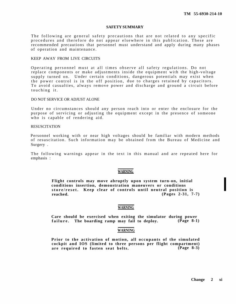
SAFETY SUMMARY
T h e f o l l o w i n g a r e g e n e r a l s a f e t y p r e c a u t i o n s t h a t a r e n o t r e l a t e d t o a n y s p e c i f i cp r o c e d u r e s a n d t h e r e f o r e d o n o t a p p e a r e l s e w h e r e i n t h i s p u b l i c a t i o n . T h e s e a r erecommended precautions that personnel must understand and apply during many phasesof ope ra t ion and main tenance .
KEEP AWAY FROM LIVE CIRCUITS
O p e r a t i n g p e r s o n n e l m u s t a t a l l t i m e s o b s e r v e a l l s a f e t y r e g u l a t i o n s . D o n o trep lace componen t s o r make ad jus tmen t s in s ide the equ ipment wi th the h igh-vo l t agesupp ly tu rned on . Under ce r t a in cond i t ions , dangerous po ten t i a l s may ex i s t whent h e p o w e r c o n t r o l i s i n t h e o f f p o s i t i o n , d u e t o c h a r g e s r e t a i n e d b y c a p a c i t o r s .To avo id casua l t i e s , a lways remove power and d i scharge and g round a c i r cu i t be fo ret o u c h i n g i t .
DO NOT SERVICE OR ADJUST ALONE
Under no c i r cums tances shou ld any pe r son reach in to o r en te r the enc losure fo r thepurpose o f se rv ic ing o r ad jus t ing the equ ipment excep t in the p resence o f someonewho i s capab le o f r ender ing a id .
RESUSCITATION
Personnel working with or near high voltages should be familiar with modern methodsof r e susc i t a t ion . Such in fo rmat ion may be ob ta ined f rom the Bureau o f Medic ine andSurgery .
The fo l lowing warn ings appear in the t ex t in th i s manua l and a re r epea ted he re fo remphasis :
WARNING
Flight controls may move abruptly upon system turn-on, initialconditions insertion, demonstration maneuvers or conditionss t o r e / r e s e t . Keep c lear o f contro l s unt i l neutra l pos i t ion i sreached. (Pages 2-31, 7-7)
WARNING
Care should be exercised when exiting the simulator during powerf a i l u r e . The boarding ramp may fail to deploy. (Page 8-1)
WARNING
Prior to the ac t ivat ion o f mot ion , a l l occupants o f the s imulatedcockpit and IOS (l imited to three persons per fl ight compartment)are required to fas ten seat be l t s . (Page 8-3)
Change 2 xi

WARNING
CAUTION
TM 55-6930-214-10
Do not discharge a CG3BR fire extinguisher in the confinedcockpit . (Page 8-4)
Due to abnormal shutdown possible hardware damage may occur.(Pages 7-1, 8-1)
x i i Change 2
TM 55-6930-214-10
CHAPTER 1
INTRODUCTION
1 - 1 . SCOPE. T h i s o p e r a t o r ' s m a n u a l c o n t a i n s c o m p l e t e o p e r a t i n g i n s t r u c t i o n sa n d p r o c e d u r e s f o r t h e c o m b a t m i s s i o n s i m u l a t o r ( C M S ) s y s t e m f o r t h e A R - 6 4( A p a c h e ) h e l i c o p t e r . T h i s m a n u a l i s o n l y f o r u s e b y a n i n s t r u c t o r / o p e r a t o r f o rt h e t r a i n i n g o f p i l o t s ( P L T ) a n d / o r c o p i l o t / g u n n e r s ( C P G ) i n t h e t e c h n i q u e sI n v o l v e d f o r a l l n o r m a l a n d e m e r g e n c y f l i g h t , t a c t i c a l m a n e u v e r s , a n d w e a p o n sd e l i v e r y o f t h e A p a c h e h e l i c o p t e r .
l - 2 . GENERAL. T h e C M S c o n s i s t s o f t w o o p e r a t i o n a l f l i g h t s i m u l a t o rcompartments (PLT and CPG), e a c h h a v i n g a s i x - d e g r e e - o f - f r e e d o m m o t i o n s y s t e m .E a c h i s e q u i p p e d w i t h a v i s u a l s y s t e m t h a t s i m u l a t e s n a t u r a l h e l i c o p t e re n v i r o n m e n t s u r r o u n d i n g s . A c e n t r a l c o m p u t e r s y s t e m c o n t r o l s t h e o p e r a t i o n o ft h e s i m u l a t o r c o m p l e x . T h e h a r d w a r e a n d s o f t w a r e t h a t c o m p r i s e t h i s c o m p l e xw e r e d e s i g n e d a n d b u i l t b y C A E - L i n k C o r p . , B i n g h a m t o n , N e w Y o r k .
a . S i m u l a t i o n . The CMS prov ides normal and emergency p rocedura l miss iont r a i n i n g a n d w e a p o n s d e l i v e r y . A d d i t i o n a l c a p a b i l i t i e s i n c l u d e n a v i g a t i o nI n s t r u m e n t f l i g h t o p e r a t i o n , d a y , d u s k , a n d n i g h t v i s u a l f l i g h t o p e r a t i o n s , a n do r d n a n c e d e l i v e r y s y s t e m s o f t h e a t t a c k h e l i c o p t e r .
b. Configurat ion. T h e b a s i s f o r s i m u l a t i o n a n d c o n f i g u r a t i o n o f t h e A H - 6 4( A p a c h e ) C M S i s t h e a i r c r a f t d a t a a v a i l a b l e a s o f 1 J u n e 1 9 8 3 u n d e r t h e b a s i cc o n t r a c t .
1-3. TECHNICAL MANUAL CHANGES. C h a n g e s a n d s u p p l e m e n t s t o t h i s m a n u a l w i l l b ep u b l i s h e d w h e n n e c e s s a r y t o a d d , d e l e t e , o r c h a n g e a n o p e r a t i n g r e q u i r e m e n t .S u c h c h a n g e s w i l l b e b a s e d o n f a c t u a l d a t a a c c u m u l a t e d a s a r e s u l t o f o p e r a t i n ge x p e r i e n c e w i t h t h e t r a i n i n g d e v i c e a n d e q u i p m e n t . c h a n g e s t o t h e t e x t a r ei n d i c a t e d b y a v e r t i c a l l i n e i n t h e o u t e r m a r g i n e x t e n d i n g c l o s e t o t h e e n t i r ea r e a o f t h e m a t e r i a l a f f e c t e d . C h a n g e s t o i l l u s t r a t i o n s a n d w i r i n g d i a g r a m sa r e i n d i c a t e d b y c h a n g e l e g e n d s .
l - 4 . FORMS AND RECORDS. M a i n t e n a n c e f o r m s a n d r e c o r d s u s e d b y a l l l e v e l s o fm a i n t e n a n c e p e r s o n n e l a r e i n D A P a m p h l e t 7 3 8 - 7 5 1 .
l - 5 . REPORTING OF ERRORS. R e p o r t o f e r r o r s o r o m i s s i o n s a n d r e c o m m e n d a t i o n sf o r i m p r o v i n g t h i s p u b l i c a t i o n b y t h e u s e r a r e e n c o u r a g e d . R e p o r t s s h o u l d b esubmi t t ed on DA Form 2028 , Recommended Changes to Pub l i ca t ions , and fo rwardedd i r e c t t o U . S . A r m y A v i a t i o n S y s t e m s C o m m a n d , A t t n : AMSAV-MC, 4300 GoodfellowB l v d . , S t . L o u i s , M O . 6 3 1 2 0 - 1 7 9 8
1 - 6 . ABBREVIATIONS. N o n s t a n d a r d a b b r e v i a t i o n s a n d a c r o n y m s u s e d i n t h i sm a n u a l a r e c o n t a i n e d i n t h e G l o s s a r y .
Change 2 1 - 1 / ( 1 - 2 b l a n k )

CHAPTER 2
SYSTEM DESCRIPTION AND OPERATION
TM 55-6930-214-10
Section I. GENERAL
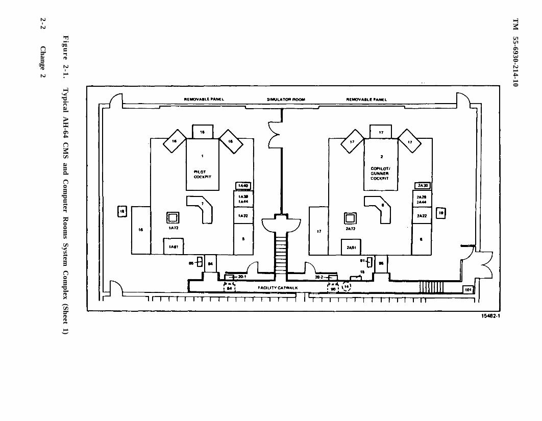
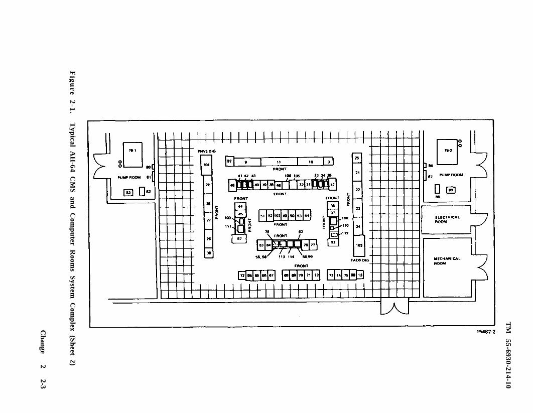
2 - 1 . OPERATIONAL SYSTEM. The AH-64 CMS is a f ixed-base simulation system designedfor t r a in ing in the use o f AH-64 Apache he l i cop te r s . Figure 2-1 shows the recom-mended general arrangement of a port ion of the system complex within the Govern-m e n t - b u i l t f a c i l i t y . The s imula to r room, where t r a in ing i s conduc ted , cons i s t so f t w o i n s t r u c t o r / t r a i n e e s t a t i o n s e q u i p p e d w i t h v i s u a l d i s p l a y s y s t e m s . Bach s t a -t ion is mounted on a six-degree-of-freedom hydraulic motion system and control ledby a cen t ra l compute r sys tem. The bas ic a reas o f the s imula to r complex a re fu r the rdesc r ibed in the fo l lowing pa ragraphs .
2 - 2 . SIMULATOR COMPARTMENTS. The s imula to r room con ta ins sepa ra te miss ion s imula -t o r c o m p a r t m e n t s f o r i n d i v i d u a l t r a i n i n g o f p i l o t a n d c o p i l o t / g u n n e r ( C P G ) t r a i n e e s .Each s imula to r compar tmen t houses a cockp i t s t a t ion and an ins t ruc to r /ope ra to r s t a -t i o n ( I O S ) . T h e c o c k p i t ( t r a i n e e ) s t a t i o n s a r e l o c a t e d i n t h e f o r w a r d p o r t i o n o fthe i r r e spec t ive compar tmen t s . Each CPG simulator compartment includes visual ,mot ion , and sound s imula t ion . T h e p i l o t a n d C P G t r a i n e e s c a n t r a i n e i t h e r i n i n d e -penden t modes o f ope ra t ion wi th sepa ra te and un ique f l igh t cond i t ions , o r in an in -tegrated mode with common training condit ions.
a . T h e p i l o t t r a i n e e s t a t i o n i s a r e p l i c a o f t h e a i r c r a f t p i l o t p o s i t i o n a n d i n -c ludes f acs imi les o f the cockp i t window a r rangements , p i lo t sea t , ma in ins t rumenta n d c o n t r o l p a n e l , f l i g h t c o n t r o l s , i n t eg ra t ed he lme t and d i sp lay s igh t sys t em(IHADSS), pi lot night vision sensor (PNVS), t a r g e t a c q u i s i t i o n / d e s i g n a t i o n s i g h t(TADS), and video display unit (VDU). Lef t and r igh t equ ipment conso les a re ac tua l
a i r c r a f t - t y p e p a r t s .
b . T h e C P G t r a i n e e s t a t i o n i s a r e p l i c a o f t h e a i r c r a f t C P G p o s i t i o n . A c t u a la i r c ra f t cockp i t equ ipment inc ludes the ma in ins t rument and con t ro l pane l , l e f t andr i g h t e q u i p m e n t c o n s o l e s , f l i g h t c o n t r o l s , integrated helmet and display sight sys-tem ( IHADSS) , op t i ca l r e lay tube (ORT) , p i lo t n igh t v i s ion sensor (PNVS) , t a rge tacqu i s i t ion /des igna t ion s igh t (TADS) , and v ideo recorder sys tem (VRS) .
c . A l l c o n t r o l s , i n d i c a t o r s . a n d p a n e l s o p e r a t e i n a s i m u l a t e d c o n d i t i o n a n d a r eidentical in appearance to those in TM 55-1520-238-10. Operator’s Manual for AH-64Apache Hel icop te r .
d . Three pairs of loudspeakers and one subwoofer in each simulator compartmentp r o v i d e r e a l i s t i c a u r a l c u e s o u n d s w i t h c h a r a c t e r i s t i c s c o r r e c t i n r e s p e c t t o l o c a -t i o n , f r e q u e n c y , a n d l o u d n e s s ( w i t h i n l i m i t s o f s a f e t y ) . A u r a l c u e s o u n d s c a n b ev a r i e d i n l o u d n e s s b y t h e i n s t r u c t o r .
e . The t r a inee cockp i t s ea t s can be v ib ra ted to s imula te the con t inuous andp e r i o d i c o s c i l l a t i o n s a n d v i b r a t i o n s e x p e r i e n c e d b y t h e c r e w d u r i n g f l i g h t c o n d i -t ions and maneuvers. V i b r a t i o n s r e p r e s e n t i n g p r o g r e s s i v e m a l f u n c t i o n s a r e a l s os imula ted . S e a t v i b r a t i o n i s i s o l a t e d f r o m t h e r e m a i n d e r o f t h e s i m u l a t o r c o m -partment by means of damping elements in the seat mounting construct ion.
Change 2 2-1
TM
55-6930-214-10
Fig
ure
2-1
.T
ypical A
H-64 C
MS
and
Com
pu
ter Room
s System
Com
plex (S
heet 1)
2-2
Change 2
TM
55-6930-214-10
Fig
ure
2-1
.T
ypical A
H-64 C
MS
and
Com
pu
ter Room
s System
Com
plex (S
heet 2)
Change
2 2-3
TM 55-6930-214-10
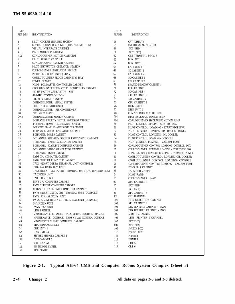
UNIT/ UNIT/REF DES IDENTIFICATION REF DES IDENTIFICATION
1 PILOT COCKPIT (TRAINEE SECTION) 58 CRT DISPLAY2 COPILOT/GUNNER COCKPIT (TRAINEE SECTION) 59 650 THERMAL PRINTER3 VISUAL INTERFACE CABINET 60 (NOT USED)4-l PILOT MOTION PLATFORM 61 (NOT USED)4-2 COPILOT/GUNNER MOTION PLATFORM 62 CRT TERMINAL MPCS-E5 PILOT COCKPIT CABINE T 63 DISK UNIT 16 COPILOT/GUNNER COCKPIT CABINET 64 DISK UNIT 27 PILOT INSTRUCTOR OPERATOR STATION 65 CPU CABINET 38 COPILOT/GUNNER INSTRUCTOR STATION 66 I/O CABINET 29 PILOT FLOOR CABINET (3-BAY) 67 CPU CABINET 210 COPILOT/GUNNER FLOOR CABINET (3-BAY) 68 I/O CABINET 111 POWER CABINET 69 CPU CABINET 1I2 PILOT FCC/MASTER CONTROLLER CABINET 70 SHARED MEMORY CABINET 113 COPILOT/GUNNER FCC/MASTER CONTROLLER CABINET 71 CPU CABINET14 400-HZ MOTOR-GENERATOR SET 72 I/O CABINET 415 400-HZ CONTROL BOX 73 CPU CABINET 516 PILOT VISUAL SYSTEM 74 I/O CABINET 617 COPILOT/GUNNER VISUAL SYSTEM 75 CPU CABINET 618 PILOT AIR CONDITIONER 76 DlSK UNIT 519 COPILOT/GUNNER AIR CONDITIONER 77 DISK UNIT 620-l PILOT MOTION CABINET 78 COMPUTER ROOM AUDIO BOX20-2 COPILOT/GUNNER MOTION CABINET 79-l PILOT HYDRAULIC MOTION PUMP21 1-CHANNEL PRIORITY SECTOR PROCESSOR CABINET 79-2 COPILOT/GUNNER HYDRAULIC MOTION PUMP 22 I-CHANNEL FRAME CALCULATOR CABINET 80 PILOT CONTROL LOADING - CONTROL BOX23 1-CHANNEL FRAME SCANLINE COMPUTER CABINET 91 PILOT CONTROL LOADING - START/STOP BOX24 l-CHANNEL VIDEO GENERATOR CABINET 82 PILOT CONTROL LOADING - HYDRAULIC POWER25 I-CHANNEL POWER CABINET 83 PILOT CONTROL LOADING - OIL COOLER26 3-CHANNEL PRIORITY SECTOR PROCESSING CABINET 84 PILOT CONTROL LOADING- CONSOLE27 3-CHANNEL FRAME CALCULATOR CABINET 85 PILOT CONTROL LOADING - VACUUM PUMP28 3-CHANNEL SCANLINE COMPUTER CABINET 86 COPILOT/GUNNER CONTROL LOADING -CONTROL BOX29 3-CHANNEL VIDEO GENERATOR CABINET 87 COPILOT/GUNNER CONTROL LOADING - START/STOP BOX30 3-CHANNEL POWER CABINET 88 COPILOT/GUNNER CONTROL LOADING -HYDRAULIC POWER31 TADS CPU COMPUTER CABINET 89 COPILOT/GUNNER CONTROL LOADING-OIL COOLER32 TADS SUPPORT COMPUTER CABINET 90 COPILOT/GUNNER CONTROL LOADING- CONSOLE33 TADS 8260AT DELTA TERMINAL UNIT (CONSOLE) 91 COPILOT/GUNNER CONTROL LOADING - VACUUM PUMP34 TADS 655 HARDCOPY UNIT 92 PNVS FLIR CABINET35 TADS 8260AT DELTA CRT TERMINAL UNIT (DIG DIAGNOSTICS) 93 TADS FLIR CABINET36 TADS DISK UNIT 94 PILOT RAMP37 TADS DISK UNIT 95 COPILOT/GUNNER RAMP38 PNVS CPU COMPUTER CABINET 96 APU CABINET 339 PNVS SUPPORT COMPUTER CABINET 97 (NOT USED)40 MAGNETIC TAPE UNIT COMPUTER CABINET 98 (NOT USED)41 PNVS 8260AT DELTA CRT TERMINAL UNIT (CONSOLE) 99 APU CABINET S42 PNVS 655 HARDCOPY UNIT l00 CRT TERMINAL43 PNVS 8260AT DELTA CRT TERMINAL UNIT (CONSOLE) 101 FIRE DETECTION CABINET44 PNVS DISK UNIT 102 APU CABINET 145 PNVS DISK UNIT 103 DIG TEXTURE CABINET - TADS46 LINE PRINTER 104 DIG TEXTURE CABINET - PNVS47 MAINTENANCE CONSOLE - TADS VISUAL CONTROL CONSOLE 105 MTU - l-CHANNEL48 MAINTENANCE CONSOLE - TAOS VISUAL CONTROL CONSOLE 106 LINE PRINTER -1-CHANNEL49 MAGNETIC TAPE UNIT COMPUTER CABINET 107 (NOT USED)50 SHARED I/O CABINET l08 (NOT USED)51 DISK UNIT - 3 109 SWITCH BOX52 DlSK UNIT - 4 110 SWITCH BOX53 SHARED MEMORY CABINET 2 1ll PRINTER54 CPU CABINET 7 112 PRINTER55 CR1 DISPLAY 113 CRT 556 650 THERMAL PRINTER 114 CRT 657 LINE PRINTER
Figure 2-1. Typical AH-64 CMS and Computer Rooms System Complex (Sheet 3)
2 -4 Change 2 All data on pages 2-5 and 2-6 deleted.

TM
55-6930-214-10
Fig
ure
2-1
.T
ypical A
H-64 C
MS
and
Com
pu
ter Room
s System
Com
plex (S
heet 4)
2-5
TM 55-6930-214-10
UNIT/REF DES
UNIT/REF DESIDENTIFICATION
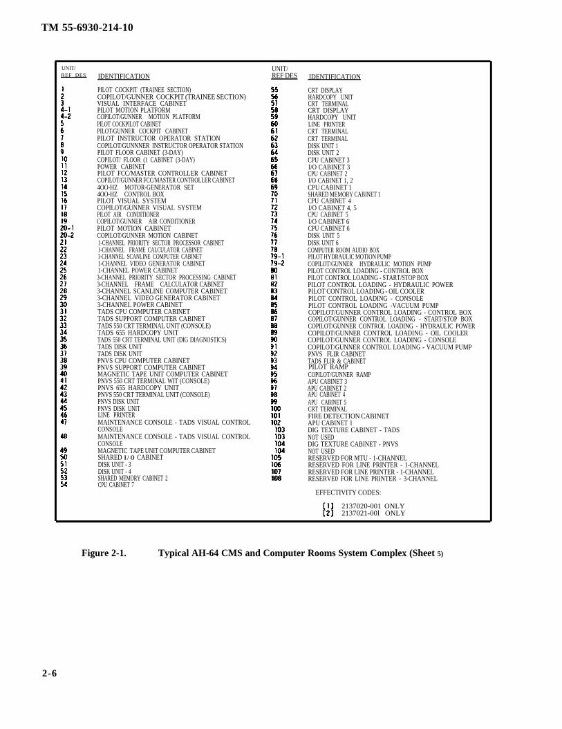
PILOT COCKPIT (TRAINEE SECTION)COPILOT/GUNNER COCKPIT (TRAINEE SECTION)VISUAL INTERFACE CABINETPILOT MOTION PLATFORMCOPILOT/GUNNER MOTION PLATFORMPILOT COCKPILOT CABINETPILOT/GUNNER COCKPIT CABINETPILOT INSTRUCTOR OPERATOR STATIONCOPILOT/GUNNNER INSTRUCTOR OPERATOR STATIONPILOT FLOOR CABINET (3-DAY)COPILOT/ FLOOR (1 CABINET (3-DAY)POWER CABINETPILOT FCC/MASTER CONTROLLER CABINETCOPILOT/GUNNER FCC/MASTER CONTROLLER CABINET4OO-HZ MOTOR-GENERATOR SET4OO-HZ CONTROL BOXPILOT VISUAL SYSTEMCOPILOT/GUNNER VISUAL SYSTEMPILOT AIR CONDITIONERCOPILOT/GUNNER AIR CONDITIONERPILOT MOTION CABINETCOPILOT/GUNNER MOTION CABINET1-CHANNEL PRIORITY SECTOR PROCESSOR CABINET1-CHANNEL FRAME CALCULATOR CABINET1-CHANNEL SCANLINE COMPUTER CABINET1-CHANNEL VIDEO GENERATOR CABINET1-CHANNEL POWER CABINET3-CHANNEL PRIORITY SECTOR PROCESSING CABINET3-CHANNEL FRAME CALCULATOR CABINET3-CHANNEL SCANLINE COMPUTER CABINET3-CHANNEL VIDEO GENERATOR CABINET3-CHANNEL POWER CABINETTADS CPU COMPUTER CABINETTADS SUPPORT COMPUTER CABINETTADS 550 CRT TERMINAL UNIT (CONSOLE)TADS 655 HARDCOPY UNITTADS 550 CRT TERMINAL UNIT (DIG DIAGNOSTICS)TADS DISK UNITTADS DISK UNITPNVS CPU COMPUTER CABINETPNVS SUPPORT COMPUTER CABINETMAGNETIC TAPE UNIT COMPUTER CABINETPNVS 550 CRT TERMINAL WIT (CONSOLE)PNVS 655 HARDCOPY UNITPNVS 550 CRT TERMINAL UNIT (CONSOLE)PNVS DISK UNITPNVS DISK UNITLINE PRINTERMAINTENANCE CONSOLE - TADS VISUAL CONTROLCONSOLE
107108
MAINTENANCE CONSOLE - TADS VISUAL CONTROLCONSOLEMAGNETIC TAPE UNIT COMPUTER CABINETSHARED I/O CABINETDISK UNIT - 3DISK UNIT - 4SHARED MEMORY CABINET 2CPU CABINET 7
IDENTIFICATION
CRT DISPLAYHARDCOPY UNITCRT TERMINALCRT DISPLAYHARDCOPY UNITLINE PRINTERCRT TERMINALCRT TERMINALDISK UNIT 1DISK UNIT 2CPU CABINET 3I/O CABINET 3CPU CABINET 2I/O CABINET 1, 2CPU CABINET 1SHARED MEMORY CABINET 1CPU CABINET 4I/O CABINET 4, 5CPU CABINET 5I/O CABINET 6CPU CABINET 6DISK UNIT 5DISK UNIT 6COMPUTER ROOM AUDIO BOXPILOT HYDRAULIC MOTION PUMPCOPILOT/GUNNER HYDRAULIC MOTION PUMPPILOT CONTROL LOADING - CONTROL BOXPILOT CONTROL LOADING - START/STOP BOXPILOT CONTROL LOADING - HYDRAULIC POWERPILOT CONTROL LOADING - OIL COOLERPILOT CONTROL LOADING - CONSOLEPILOT CONTROL LOADING -VACUUM PUMPCOPILOT/GUNNER CONTROL LOADING - CONTROL BOXCOPILOT/GUNNER CONTROL LOADING - START/STOP BOXCOPILOT/GUNNER CONTROL LOADING - HYDRAULIC POWERCOPILOT/GUNNER CONTROL LOADING - OIL COOLERCOPILOT/GUNNER CONTROL LOADING - CONSOLECOPILOT/GUNNER CONTROL LOADING - VACUUM PUMPPNVS FLIR CABINETTADS FLIR & CABINETPILOT RAMPCOPILOT/GUNNER RAMPAPU CABINET 3APU CABINET 2APU CABINET 4APU CABINET 5CRT TERMINALFIRE DETECTION CABINETAPU CABINET 1DIG TEXTURE CABINET - TADSNOT USEDDIG TEXTURE CABINET - PNVSNOT USEDRESERVED FOR MTU - 1-CHANNELRESERVED FOR LINE PRINTER - 1-CHANNELRESERVED FOR LINE PRINTER - 1-CHANNELRESERVE0 FOR LINE PRINTER - 3-CHANNEL
EFFECTIVITY CODES:
2137020-001 ONLY2137021-00l ONLY
Figure 2-1. Typical AH-64 CMS and Computer Rooms System Complex (Sheet 5)
2-6

TM 55-6930-214-10
f . The ambient temperature of the simulator compartment and the cockpit iscontrol led by adjust ing the thermostat located on the back wall of the compart-ment. Conditioned air is ducted through the compartment area and the normalhel icopter cockpit heat ing and defrost ing ducts . The cockpit environment controlsystem switches and controls are nonfunctional .
g. A platform step is provided alongside each cockpit to facilitate entrance ande x i t . Low-level s tep l ight ing is provided for safety and is a function of thefacility power.
2-3. INSTRUCTOR/ OPERATOR STATIONS. The ins t ruc to r /opera to r s t a t ions ( IOS) a relocated adjacent and to the rear of the cockpit In each simulator compartment.(Refer to Section II for further detai ls .) The IOS allows instructors/operators tocontrol the training program and effect ively monitor and evaluate trainee perform-ance . During training, the pilot and CPG IOS function in either independent orintegrated modes of operat ion.
2-4. MOTION SYSTEM. Each simulator compartment is mounted on a six-degree-of-freedom (6-DOF) motion system consisting of a moving platform assembly driven andsupported from below by six identical hydraulic actuators . The motion system iscapable of providing cues for pi tch, rol l , yaw, lateral , longitudinal , and vert icalmovements. System motion can be either Independent (without simultaneous motion inany other degree of freedom) or in any combination desired to produce real-timedynamic motion cues.
a . Flight s imulat ion includes combined motion representing changes in aircrafta t t i t ude a s a d i r ec t r e su l t o f f l igh t con t ro l s , rough a i r , and wind , and changes inaircraft weight and center-of-gravity result ing from fuel consumption or weapon andammunition depletion. Also, motion effects such as droop-stop pounding, blades ta l l , b l ade imba lance , damper fa i lu re , blades out-of-track, and touchdown impactcan be produced.
b. The computer-controlled simulation program causes the motion system to re-spond realistically to aerodynamic forces and moments within the mechanical limitsof the system. All motions except pitch are imperceptibly washed out to theneutral posi t ion after the computed accelerat ions have reached zero. P i t chatt i tude is maintained as necessary to simulate sustained longitudinal accelerat ioncues. Acce le ra t ion onse t cues a re sca led as l a rge a s poss ib le to fu l ly u t i l i ze therange of motion capabil i t ies of each degree-of-freedom.
c. Depending on the part icular f l ight program, the motion system responds tocomputer input signals as noted in the following examples:
(1) Ground condit ions. The motion system provides the vibrat ional indicat ionsappropr i a t e to mot ion o f the a i r c ra f t du r ing s t a r tup . The system produces a random,low-frequency, low-ampli tude. mult idirect ional osci l lat ion with reasonably abruptapp l i ca t ion . The computer simulation program varies the amplitude of oscillationto r ep roduce the i r r egu la r i t i e s o f l e s s than idea l f l i gh t t akeof f cond i t ions .
(2) Takeoff and landing. The motion system provides s imulated real is t ice f fec t s fo r a l l fo rms o f t akeof f , f l igh t , and l and ing cond i t ions .
Change 1 2-7
TM 55-6930-214-10
(a) During engine runup and ini t ial hover for takeoff , the ground perform-ance of the motion system is as described in paragraph (1) . The motion systemmaintains an at t i tude appropriate for hover and provides the correct indicat ions oft akeof f . Appropriate motion effects occur as a result of changes in accelerat ionand l i f t du r ing t r ans i t ion to fo rward f l igh t .
(b ) S imi la r e f fec t s a re r ep roduced dur ing the l and ing phase . The motionsys tem causes appropr i a t e long i tud ina l , ve r t i ca l , and low-frequency vibratione f fec t s to occur a s in the he l i cop te r . The motion system correctly reproduces theland ing impac t accord ing to the ex i s t ing a i r c ra f t a t t i t ude and ve r t i ca l and s ide -s l i p v e l o c i t i e s . When the vertical momentum is greater than the absorption capa-b i l i t i e s o f the l and ing gea r , landing bounce is s imulated.
( 3 ) N o r m a l f l i g h t . The motion system correctly simulates the complex and re-peated cues occurring during maneuvers associated with normal f l ight condit ions.The random introduction of varying degrees of turbulence produces the appropriatemotion effects of small variat ions in yaw and rol l , c l imb or descent , and air-speed. Superimposed upon the flight maneuver motions is the background motion.The mot ion sys tem prov ides cha rac te r i s t i c pe r iod ic osc i l l a t ions o f the a i r c ra f t ,l a t e r a l i n s t a b i l i t y , and aircraft vibrations up to a maximum of 5 cycles persecond. Continuous higher frequency vibrat ions are s imulated using the seat shakerin l ieu of the motion system.
(4 ) Abnormal f l igh t . The motion system correct ly reproduces the effects ofro to r ou t -o f - t r ack and ro to r ou t -o f -ba lance fa i lu res . The motion simulated includesthe effect of momentary incorrect control inputs as well as condit ions appropriateto malfunct ions. An aircraft hydraulic system fai lure result ing in abnormal direc-t ional control of the aircraft is provided by appropriate motion cues. High air-speed characterist ics and tr im change effects are also produced by the motionsystem.
2-5. VISUAL SYSTEM. The pilot and CPG trainee stat ions are provided with forward,lef t , and r ight s ide window visual displays. The visual generation system providesimagery to every sensor display in the CMS, including IHADSS, PNVS, OTW scene, VDU,and TADS/FLIR. (Refer to Chapter 6 for visual systems detai ls . )
2-6. COMPUTER SYSTEM. In a nonrigorous sense, the CMS consists of the pilot maincomputational system (MCS), made up of central processing units (CPU’s) 1, 2. and 3and their associated auxiliary processing units (APU's); and the CPG MCS, made upof CPU’s 4, 5, and 6 and their associated APU’s. Bach CPU has private memory thatonly I t and i ts associated APU’s can access. The CPG MCS has complex shared memorythat only CPU’s 4, 5, and 6 can access. The pilot MCS has complex shared memorythat only CPU’s 1, 2, and 3 can access. In addit ion, a memory region called globalmemory exists that all six CPU’s can access.
2-8
TM 55-6930-214-10
S e c t i o n I I . INSTRUCTOR/OPERATOR STATION DESCRIPTION
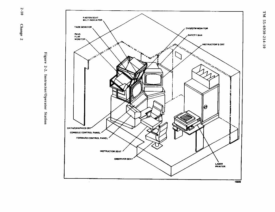
2 - 7 . GENERAL DESCRIPTION. Each instructor/operator station (IOS) accommodates onei n s t r u c t o r a n d a n o b s e r v e r . (F igure 2 -2 ind ica tes the a r rangement o f thei n s t r u c t o r / o p e r a t o r s t a t i o n s a n d t h e i r r e l a t i o n s h i p w i t h t h e t r a i n e e s t a t i o n s . )The IOS arrangement permits close, direct contact between instructors/operators andt r a i n e e s . The locations of the forward control panel and the console control panelprovide convenient control of each or both cockpits , and direct contact with theCRT displays of information required to monitor , guide, and evaluate trainee per-formance . Br ie f desc r ip t ions o f the va r ious f ea tu res o f the ins t ruc to r a reas a reg iven in the fo l lowing pa ragraphs .
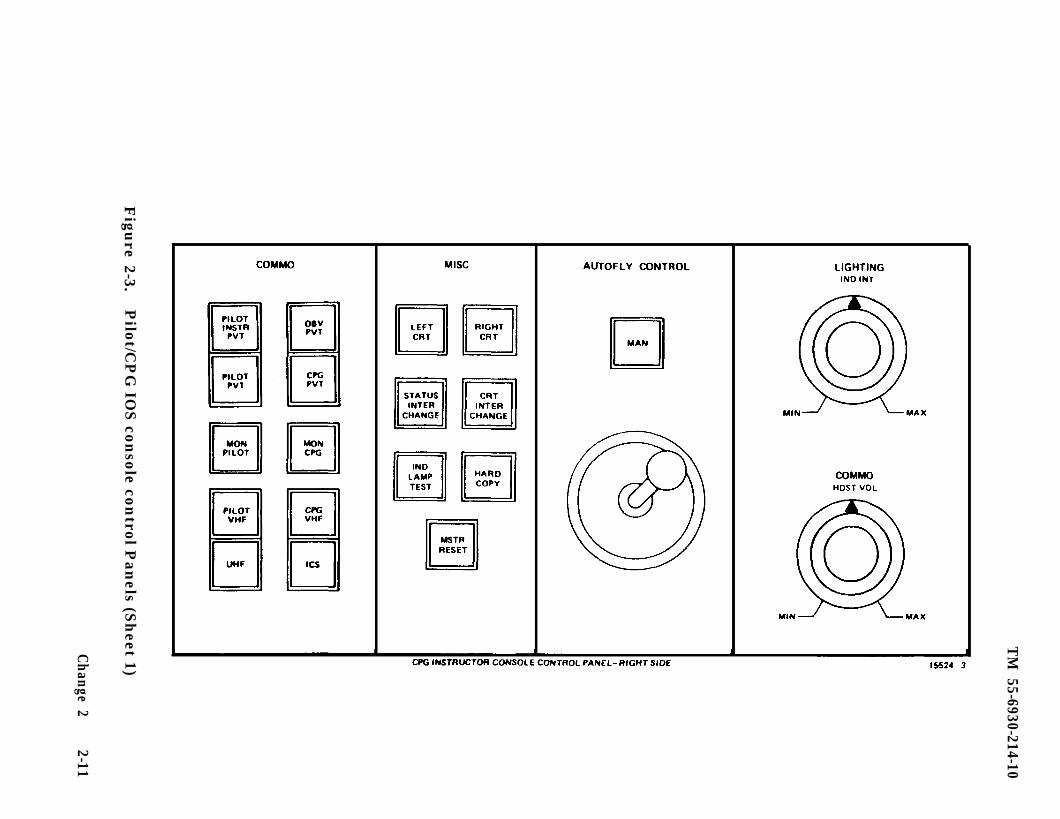
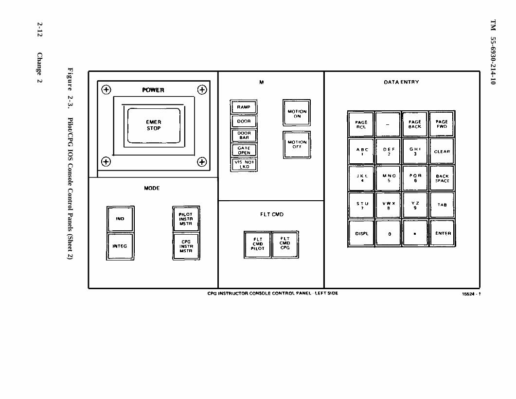
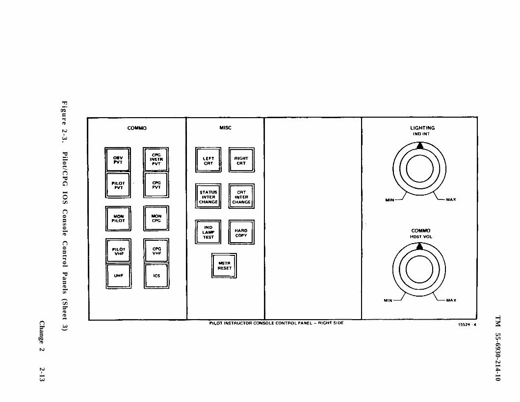
2 - 8 . IOS CONTROL PANELS. AT each IOS, two con t ro l pane l s p rov ide con t ro l andmanagement o f s imula to r t r a in ing . The pane l s a re s imi la r , w i th the excep t ion o fspecial controls at the CPG IOS that are used in conjunction with automatic f l ightprograms when the CPG cockpit is operated in the independent mode. (Figure 2-3i l l u s t r a t e s t h e p i l o t a n d C P G I O S c o n s o l e s c o n t r o l p a n e l s . ) T o t h e l e f t o f t h eCRT’s is the forward control panel (f igure 2-4), which provides selection controlsf o r t h e i n s t r u c t o r s v i d e o m o n i t o r , d i s c r e t e c o n t r o l s f o r s o m e t r a i n i n g f e a t u r e s ,and a discrete control for communications with the computer room. On the bulkhead,l e f t o f t h e c o c k p i t , i s a c o n t r o l p a n e l f o r o b s e r v e r c o m m u n i c a t i o n s , t h e I O Sa m b i e n t l i g h t i n g , a n d s t e p l i g h t s . (The trainee flight compartment layout is showni n f i g u r e 2 - 6 . ) P a n e l l a y o u t i s s u c h t h a t m a x i m u m e f f i c i e n c y a n d e a s e o fc o n t r o l l i n g a n y t r a i n i n g s i t u a t i o n i s e n s u r e d . Two CRT’s provide simultaneousviewing of the PLT and CPG PNVS/TADS information. Related CRT display controls ,p r o b l e m f l i g h t c h a r a c t e r i s t i c s a n d c o n t r o l s , and simulator setup and communicationsc o n t r o l s a r e o n t h e c o n s o l e c o n t r o l p a n e l . O n l y m i n o r d i f f e r e n c e s e x i s t i n t h econ t ro l l abe l ing and func t ions be tween the p i lo t and CPG IOS pane l s .
2 - 9 . TRAINER CONTROL PANELS. The pilot and CPG trainee control panels are locateda l o n g t h e o u t e r e d g e o f t h e l e f t s i d e c a n o p y r a i l s . ( S e e f i g u r e 2 - 7 . )
2 -10 . INSTRUCTION SEATS. The ins t ruc to r sea t i s moun ted on a t r ack to a l low fo r -ward o r r ea rward ad jus tmen t fo r op t imum pos i t ion ing . The sea t a l so has a 360-degree swivel capabil i ty, as well as up and down adjustment, to enable the instruc-to r to ad jus t fo r op t imum CRT and /o r cockp i t s t a t ion ins t rumen t s v i ewing ang le .P o s i t i v e l o c k s i n t h e t r a c k , s w i v e l , a n d h e i g h t s y s t e m s p r e v e n t t h e s e a t f r o mmoving in r e sponse to mot ions o f the s imula to r compar tmen t . The normal position oft h e s e a t p l a c e s t h e i n s t r u c t o r ’ s e y e l e v e l s l i g h t l y a b o v e a n d t o t h e l e f t o f t h et r a i n e e ’ s e y e l e v e l t o p e r m i t e a s i e r s u r v e i l l a n c e o f t h e c o c k p i t i n s t r u m e n t a n dc o n t r o l p a n e l s .
2 -11 . OBSERVER SEATS. An observer seat , equipped with fold-down arms and ana b d o m i n a l s e a t b e l t , i s l o c a t e d t o t h e l e f t o f t h e I O S c o n s o l e i n t h e s i m u l a t o rcompartment. I t i s m o u n t e d o n a t r a c k t o a l l o w s i d e t o s i d e a d j u s t m e n t f a c i l i -t a t i n g o v e r a l l v i e w i n g o f i n s t r u c t o r / t r a i n e e p e r f o r m a n c e . An intercommunicationssys tem ( ICS) con t ro l pane l on the wa l l and sepa ra te headse t j ack in the ce i l ing ,w i t h a c o r d o f s u f f i c i e n t l e n g t h s o a s t o b e n o n i n t e r f e r r i n g , p r o v i d e o b s e r v e rcommunica t ion wi th the ins t ruc to r .
Change 2 2-9
TM
55
-69
30
-21
4-1
0
Figu
re 2-2. Instru
ctor/Op
erator Station
2-10C
hange 2
TM
55-6930-214-10
Figu
re 2-3.P
ilot/CP
G IO
S con
sole control P
anels (S
heet 1)
Change 2
2-11
TM
55-6930-214-10
Fig
ure
2-3
.P
ilot/CP
G IO
S Console C
ontrol Panels (Sheet 2)
2-12C
hange 2
TM
55-6930-214-10
Fig
ure 2
-3.
Pilot/C
PG
IO
S
Con
sole C
ontrol
Pan
els (S
heet
3)
Change
22-13

TM
55-6930-214-10
Fig
ure
2-3
.
Change
2
Pilot/C
PG
IO
S
Con
sole C
ontrol
Pan
els (S
heet
4)
2-14
15523CPG ISTRUCTOR FORWARD CONTROL PANEL
TM 55-6930-214-10
Figure 2-4. Pilot/CPG IOS Forward Control Panels
Change 2 2-15/(2-16 blank)

15527
TM 55-6930-214-10
Figure 2-6. Trainee Station
Change 2 2-17
TM 55-6930-214-10
15528
Figure 2-7. Trainee Control Panel
2-18 Change 2
TM 55-6930-214-10
2-12 . IOS AREA LIGHTING. T h e I O S a r e a i s p r o v i d e d w i t h a v a r i a b l e - i n t e n s i t yo v e r h e a d l i g h t , m a p l i g h t , and clip-on light to provide ambient illumination duringa n y p h a s e o f t h e t r a i n i n g . A black curtain is provided to shield the crew memberstat ion from I O S l i gh t ing .
2-13. INSTRUCTOR INTERCOMMUNICATION SYSTEM. Headset cords and microphone switchesf o r e a c h i n s t r u c t o r a r t i n s t a l l e d t o p e r m i t m i n i m u m i n t e r f e r e n c e w i t h t h e t r a i n i n gf u n c t i o n . Communica t ion on a p r iva te bas i s i s p rov ided fo r in s t ruc to r s , obse rve r s ,and the computer room. ( A v i s u a l w a r n i n g c u t i s p r o v i d e d f o r t h e i n s t r u c t o r s , a n dan aura l warn ing cu t i s p rov ided in the compute r roa r . )
2-14. TIME REFERENCES. A digital readout time-of-day clock is located above theobserver control panel on the wall to the left of the IOS.
Change 2 2-19
TM 55-6930-214-10
S e c t i o n I I I . MODES OF OPERATION
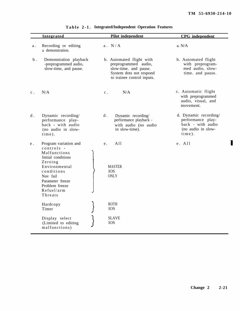
2-15. GENERAL. The CMS can opera te on- l ine in th ree ca tegor ies : t r a i n i n g , a u t o -f ly , and demons t ra t ion . The CM can be used wi th the v i sua l d i sp lays and /o r mot ionsys tem in ope ra t ion . Wi th two v i sua l sys t ems , bo th cockp i t s can have ou t - the -win-dow (OTW) visual displays. The p i lo t o r CPG cockp i t can e i the r be opera ted inde-penden t ly , o r bo th can be opera ted as on a s ing le in teg ra ted miss ion as c rew memberso f t h e s a m e a i r c r a f t . The CMS must be in the freeze mode to set up or edit a de-mons t r a t ion . Formula t ion o f a demons t ra t ion invo lves r eco rd ing and s to r ing thec h a r a c t e r i s t i c s o f p a r t i c u l a r f l i g h t o r m i s s i o n p r o f i l e s i n t h e c o m p u t e r m e m o r y .An accompanying audio commentary can also be recorded and synchronized to themotion. Dur ing p layback o f a r ecorded demons t ra t ion fo r t r a in ing , the CMS f l i e si t s e l f t h r o u g h a n e s t a b l i s h e d m i s s i o n e x e r c i s e i n a h a n d s - o f f - t h e - c o n t r o l s c o n d i -t i o n . As the CMS re f l i e s the miss ion , a l l mot ion , au ra l sounds , in s t rument ind ica -t i o n s , a n d v i s u a l d i s p l a y s c e n e s a r e r e c r e a t e d . Th i s can show the t r a inee p i lo ta n d / o r C P G p a r t i c u l a r s t a n d a r d m a n e u v e r s s p e c i a l f l i g h t p r o b l e m s . ( F u r t h e r i n -fo rmat ion on the demons t ra t ion ca tegory i s g iven in Chap te r 7 o f th i s manua l . ) Thesys tem fea tu res ava i l ab le to each cockp i t fo r the modes o f bo th independen t and in -t e g r a t e d o p e r a t i o n a r t o u t l i n e d i n t a b l e 2 - l .
2 -16 . TRAINING. T h e a d m i n i s t r a t i o n o f t r a i n i n g t o t r a i n e e s o c c u p y i n g t h e p i l o t o rC P G c o c k p i t s i s u n d e r t h e p o s i t i v e c o n t r o l o f t h e i n s t r u c t o r . For independentmodes , the ins t ruc to r can employ au to f ly wi th au tomat ic pe r fo rmance record ing , p re -corded demons t ra t ions . In i t i a l cond i t ions , p rep rogrammed mal func t ions , o r o the ra ids th rough the use o f con t ro l s and CRT d i sp lays p rov ided a t t he IOS. In fo rmat ionto be d i sp layed a t t he IOS i s upda ted con t inuous ly du r ing the t r a in ing p rogram tor e f l e c t c u r r e n t s t a t u s .
a . Independen t Tra in ing . In the independent mode, e a c h i n s t r u c t o r i s f r e e t ocon t ro l any o f the manua l f ea tu res o f the CMS. Th i s inc ludes inse r t ing own cockp i tm a l f u n c t i o n s , c h a n g i n g i n i t i a l c o n d i t i o n s , cu r ren t cond i t ions and weapon load ingconf igura t ions , and se lec t ion o f nav /comm equ ipment and fac i l i t i e s . I n a d d i t i o n , at r a in ing sess ion can be f rozen , and a 15- second to 5 -minu te dynamic p layback o f thec u r r e n t t r a n s p i r e d f l i g h t c o n d i t i o n s i s a v a i l a b l e f o r r e v i e w .
b . I n t e g r a t e d T r a i n i n g . I n t h e i n t e g r a t e d m o d e , t h e a d m i n i s t r a t i o n o f t r a i n i n gt o t h e t r a i n e e s i n b o t h c o c k p i t s i s u n d e r t h e p o s i t i v e c o n t r o l o f e i t h e r t h e P L T o rthe CPG ins t ruc to r . T h e c o n t r o l l i n g i n s t r u c t o r c o n t r o l s t h e m a n u a l f e a t u r e s o f t h eCMS. T h i s i n c l u d e s i n s e r t i n g m a l f u n c t i o n s , c h a n g i n g i n i t i a l c o n d i t i o n s , s e l e c t i o no f n a v / c o m m e q u i p m e n t a n d f a c i l i t i e s , a n d a l l a s p e c t s o f t r a i n i n g . T h e o t h e r i n -s t ruc to r genera l ly ac t s a s an obse rve r and has use o f on ly the emergency con t ro l s ,h a r d c o p y r e q u e s t s , t i m e r , a n d C R T d i s p l a y s e l e c t ( w i t h o u t e d i t i n g c a p a b i l i t y ) . A l la spec t s o f t r a in ing in the in t eg ra ted mode can be accompl i shed wi thou t the o the rinstructor present.
2 -17 . AUTOFLY. T h e n e e d f o r a p i l o t a t a l l t i m e s i s o v e r r i d d e n b y t h e u s e o f t h eau tomat i c f l igh t mode o f ope ra t ion . When the CPG cockpit is operated in the inde-penden t mode , the CMS f l i e s i t s e l f to compensa te fo r the miss ing p i lo t . The au to -f l y f e a t u r e f l i e s t h e c o p i l o t / g u n n e r t h r o u g h a p r e r e c o r d e d a i r c r a f t m a n e u v e r , o rse r i e s o f maneuvers . When active in the autofly mode, the CMS performs as if ap i l o t w e r e a c t u a l l y f l y i n g t h e a i r c r a f t . D u r i n g t h e a u t o f l y , t h e i n s t r u c t o r c a ni n t e r r u p t t h e f l i g h t a n d a s s u m e m a n u a l c o n t r o l o f t h e s i m u l a t e d a i r c r a f t h e a d i n ga n d a l t i t u d e ( i . e . , a c t a s t h e p i l o t ) . By doing so, the CPG is al lowed addit ionalt i m e , i f n e e d e d , t o o p e r a t e s e n s o r , s ighting, and weapon systems.
2-20 Change 2
TM 55-6930-214-10
T a b l e 2 - 1 . Integrated/Independent Operation Features
Integrated Pilot independent CPG independent
a . Recording or editing a . N / A a. N/Aa demonstration.
b . Demonstration playback b. Automated flight with b. Automated flight-preprogrammed audio, preprogrammed audio, with preprogram-slow-time, and pause. slow-time. and pause. med audio, slow-
System dots not respond time. and pause.to trainee control inputs.
c . N/A c . N/A c. Automatic flightwith preprogrammedaudio, visual, andmovement.
d . Dynamic recording/ d . Dynamic recording/ d. Dynamic recording/performance play- performance playback - performance play-back - with audio with audio (no audio back - with audio(no audio in slow- in slow-time). (no audio in slow-t i m e ) . t i m e ) .
e . Program variation andc o n t r o l s -Mal func t ionsInitial conditionsZero ingEnvironmentalc o n d i t i o n sNav failParameter freezeProblem freezeRefue l / a rmT h r e a t s
e . A l l e . A l l
MASTERIOSONLY
Hardcopy ROTHTimer IOS
Display select SLAVE(Limited to editing IOSmal func t ions )
Change 2 2-21

TM 55-6930-214-10
2-18. DEMONSTRATION. For demonstration playback, the instructor can select a num-ber of prerecorded demonstrat ions. Each demonstration can be further subdividedinto nine separate maneuvers. These individual maneuvers can be selectivelyaccessed, or they can be rearranged to formulate one mission for playback. Synch-ronized audio accompanying the demonstration is not available to the pilot or CPGcompartment if the other instructor has already chosen the same demonstrat ion withaudio . The instructor can delete a demonstration at any point.
2-22
TM 55-6930-214-10
Section IV. TRAINING CAPABILITIES
2-19. GENERAL. The CMS is a fully operational combat mission simulator withseparate pilot and CPG simulator compartments. Each has its own six degree-offreedom motion system, visual system, and instructor/operator station. Each cock-pit station duplicates its portion of the actual helicopter cockpit configuration.The CMS simulates, in real-time, applicable normal and emergency aircraft operationwith respect to both transient and steady-state flight conditions. Operation ofthe CMS involves such capabilities as engine performance, flying qualities, weaponssystems performance and operation, aircraft systems performance and operation,radio communications and navigation systems performance and operation, environ-mental effects, nap-of-the-earth operation, and flightpath. Simulation is reflec-ted by appropriate trainee and IOS station instrument and aural indications,aircraft control reactions, visual cue presentations, and display traces respondingto trainee, instructor, and computer-programmed control inputs. Use of the CMSwhen the visual and/or motion system is inoperative severely limits training capa-b i l i t i e s .
2-20. TRAINING OBJECTIVES. The CMS can be used to provide transition trainingproficiency flying, and weapons delivery practice. The CMS can also be used totrain pilots to perform all normal and emergency flight maneuvers, weapons deliveryoperations, nap-of-the-earth flight and navigation, and starting, runup, and shut-down procedures. It is capable of full mission simulation, and it can be used fortraining of both the pilot and CPG simultaneously on the same mission or indepen-dently on different missions. This is accomplished in either integrated or inde-pendent operating modes of visual, motion, and cockpit simulation available to bothpilot and CPG in any situation. The CMS can also be used for the training ofinstructor pilots.
NOTE
Training maneuvers are not limited to those listed in this paragraph.
a. Basic Maneuvers. Training for the following basic aircraft maneuvers can beconducted:
Cockpit procedures Normal approach to a hoverStartup and initial hover Normal approach to the groundHovering flight (including turns) Straight-and-level flightTraffic pattern Level turnsNormal takeoff from a hover Straight climbs and descentsNormal takeoff from the ground Turning climbs and descents
b. Advanced Maneuvers. Training for the following advanced aircraft maneuverscan be conducted:
Maximum performance takeoffSteep approachBasic autorotation (power recovery and termination with power)DASE OFF (digital automatic stabilization equipment) flightRunning landingsHigh-speed flight
Change 1 2-23
TM 55-6930-214-10
High-speed dive (normal)High-speed dive (steep)Running takeoffNight operations
c. Emergency Maneuvers. Training for the following emergency aircraft maneuverscan be conducted:
Forced landings (normal and high speed)Autorotative glides and turnsDecelerationsSimulated tail rotor control failureSimulated hydraulic failureTransient torque controlEmergency procedures (including emergency shutdown procedures)Autorotations with turns (power recovery, termination with power, touchdown)Hovering autorotationBasic autorotations (power recovery, termination with power, touchdown)Low flat glide autorotationLow-level, high-speed autorotation (with power recovery, termination with
power, touchdown)
d. Nap-of-the-Earth Maneuvers. Training for the following low-level nap-of-the-earth (NOE) aircraft maneuvers can be conducted:
Low-level navigation techniquesHovering in and out of ground effectNOE takeoffNOE flightNOE approachNOE downwind takeoffNOE downwind flightNOE downwind approachNOE navigationNOE radio procedureNOE quick stopMasking and unmasking techniquesScan and detection techniques
e. Gunnery Maneuvers. Training for the following tactical gunnery maneuvers canbe conducted:
Weapons cockpit proceduresInternal Boresight settingDiving fireRunning fireDiving to running fireLow-level/NOE firing (combat sight setting)Low-level/NOE firing
2-21. SIMULATION SYSTEM CAPABILITIES. Capabilities of the various areas and sys-tems of the CMS are outlined below.
a. Visual Area Navigation. A simulated area of terrain 32 km by 40 km contains28 navigation aids (radio stations).
2-24 Change 2
TM 55-6930-214-10
b. Nav/Comm Radio. Navigation and communication radio capabilities are providedin Chapter 3.
c. Tactical Environment. Any of 15 different weapon loading configurations areavailable for firing at 10 active targets, five of which can be moving, selectedfrom the targets available. Appropriate weapon effects are used to enhance ownweapons targets and threats.
d. Atmospheric Environment. The simulated environment can be controlled by theinstructor to provide variable winds, turbulence levels (light, moderate, severe),gusts, temperature, and barometric pressure. Temperature in degrees centigrade andbarometric pressure in inches of mercury are displayed on the instructor/operatorstation (IOS) and are referenced at mean sea level. The indications presented onthe cockpit instruments, and as seen by the computer, are pressure altitude and
temperature based upon application of standard lapse (2OC/1000 feet).
e. Motion Cues. A six-degree-of-freedom motion base provides motion cues ofpitch, roll, yaw, heave, longitudinal, and lateral. The simulation is further en-hanced by a seat vibration system for both the pilot and CPG seats. The seatvibration system can provide continuous and periodic oscillations and vibrationsexperienced during normal and emergency flight conditions, including progressivemalfunctions. Both motion and vibration can be selected or deselected at the IOSconsole CRT.
f . Environmental Sound Cues. Environmental sound cues are available at fivelevels of loudness and can be selected and varied at the IOS console CRT.
g. Seat Positions. Each flight simulator compartment provides seat positionsfor one trainee, an instructor, and an observer.
h. Special Capabilities. The CMS has some limitations that preclude its utiliza-tion for training in certain maneuvers. The most serious limitation is in the areaof visual field-of-view required for contact flight. On the other hand, the CMSprovides the following unique capabilities that the operational aircraft cannotprovide:
(1) Freeze simulator action at any instant.
(2) Initiate a training program at any one of 45 predefined locations withinthe game environment from which the flight can proceed.
(3) Reset to an initialization point that has been modified.
Reset is identical to initialization, indicated by freezeindicator blinking.
(4) Override an impending aircraft crash.
(5) Dynamically record and play back up to previous 5 minutes of a currentf l ight .
(6) Insertion of up to 15 of approximately 336 malfunctions simultaneously.
2-25
TM 55-6930-214-10
(7) Demonstrate prerecorded maneuvers automatically.
(8) Independent CPG task accomplished with the use of AUTO FLY.
(9) Monitor program progress and trainee performance.
(10) Freeze flight parameters selectively.
(11) Administer audio briefings automatically.
(12) Stop and abort a program at any time in event of emergency.
(13) Retrieve stored performance data via hardcopy printer/plotter.
(14) Fully control training program from IOS, or limited control from traineecockpit station.
(15) View on IOS CRT end/or obtain hardcopy time history plots of airspeed,altitude, and ground track.
(16) Alter environmental conditions that act on the aircraft.
(17) Compute and display ground-controlled approach (GCA) commands.
(18) Train pilot and CPG in safety.
(19) Train pilot and CPG both independently and/or simultanously.
(20) Display up to 10 interactive hostile threats.
2-22. VISUAL SYSTEM CAPABILITIES. The full-color visual simulation system, com-bined with computer-generated visual effects, provides a realistic view of groundand sky conditions to the pilot and CPG trainees. (Additional information on thevisual system and its capabilities is contained in Chapter 6).
2-23. TRAINING TASKS. Training of pilot and CPG trainees is carried out in eitherintegrated or independent operating modes of visual, motion, and cockpit simulation.The task of the trainees is to become thoroughly knowledgeable with all aspects ofthe pilot and CPG positions of the actual helicopter. The instructor task is tomaintain complete control of simulated conditions for training and to fully monitortrainee performance in all normal and emergency operational aspects of thehelicopter.
a. Simulated Aircraft. The M-64 Apache is a twin-turbine-engine, four-blade-rotor, high-performance attack helicopter with a two-man crew seated in tandem, theCPG in front of the pilot. The primary mission of this aircraft is that of anarmed tactical aircraft with capabilities including weapons delivery, low-altitudehigh-speed flight, nap-of-the-earth flight, search and target acquisition, recon-naissance, multiple-weapons fire support, and troop aircraft support.
b. Fliqht Control. The simulated flight can be controlled by the following:
(1) By the pilot in the integrated mode with the CPG acting as CPG only,unless CPG control is selected by the master instructor.
2-26 Change 2
TM 55-6930-214-10
(2) By both pilot and CRG in the independent mode, each flying completelyseparate and independent aircraft.
(3) By the instructor via prerecorded demonstrationsindependent modes.
c. Trainee Tasks. The task of a trainee in the CMS is to learn, practice, andverify the skills and knowledge associated with the pilot and CPG positions on theactual helicopter. The CMS provides transition training, proficiency flying,weapons delivery practice, and the training of instructor pilots.
(1) through (3) (Deleted)
d. Instructor Tasks. The task of the instructor is to facilitate and verifylearning by the trainee crew. Instructional and operational functions include:
in either integrated or
(1)
(2)
(3)
(4)
(5)
(6)
(7)
(8)
(9)
(10)
(11)
(12)
(13)
(14)
(15)
Selection of mission or lesson plan.
Preflight briefing of trainees.
Demonstration of proper techniques and procedures.
Observation, monitoring, and critique of trainee performance.
Evaluation of individual or crew training needs.
Identification of areas that need coaching or more special practice.
Scheduled structuring of subsequent practice.
Preproblem setup of helicopter configuration and position.
Setup and modification of environmental conditions.
Random insertion and removal of simulated malfunctions.
Hardcopy recording of important aspects of trainee performance.
Monitoring and controlling operational status of simulator.
Serving as an air traffic controller when appropriate.
Act as other factors, i.e., remote designator on the battlefield.
Act as controller for threat forces.
Change 2 2-27
TM 55-6930-214-10
e. Automation of Instructional Functions. Many facets of the functions notedabove have been automated, thus unburdening the instructor. An additional value ofthis automation is the standardization it provides. Among the more importantfeatures of the CMS in terms of automating instructor function are the following:
(1) Demonstration maneuvers. Demonstration of maneuvers and problems for theCPG in which previously recorded pilot data is played back is available.
(2) Autofly maneuvers. When operated in the independent mode, the CMS isflown for the CPG through a prerecorded maneuver or series of maneuvers. Thisenhances the role of the CMS by performing for the CPG trainee without the presenceof the pilot.
(3) Ground-controlled approach (GCA). Proper GCA instructions based on thesimulated position are displayed on the IOS CRT. This enables the instructor tosimply read them, rather than having to interpret graphic displays.
(4) Trainee scoring and evaluation. Evaluation data is available to theinstructor from CRT displays and from direct observation of the trainees and theirinstruments and indicators.
f . Briefing. Briefings prior to training missions are live. In this manner,the trainees are provided with an up-to-date report of what is expected through-out the mission. Also, any unclear areas of the operation can be resolved with aquestion-and-answer session prior to beginning.
g. Critique. While a critique of trainee performance after a training exerciseis not automated, it can be based on a comprehensive and standardized set ofcriteria. The critique is aided by the available hardcopy records of traineeperformance. Such pictures are often worth the proverbial thousand words ofinstructor comment. A learning feature that can be most useful in critiquing isthe 15-second to 5-minute dynamic playback of trainee performance. This can beaccomplished either in real-time or in slow-time. Another function is the hardcopyprint of graphic displays available at instructor discretion.
h. Cueinq. Cueing is sometimes defined as the provision of stimuli, usually ofa secondary or faint nature, that guide the trainee to the correct response. Suchcueing, sometimes called prompting, is of considerable value in programmed instruc-tion. Application of prompts, or cues, are gradually withdrawn or faded as learn-ing progresses. Cueing has a somewhat different meaning in the context of the
2-28 Change 2

TM 55-6930-214-10
CMS. Cues for action are the stimuli normally present in helicopter flight, suchas instrument and indicator readings, positions of cockpits controls, aspects ofthe out-the-window visual scene, cockpit motion and vibration, feel of thecontrols, and sounds associated with helicopter operations. These cues aresimulated with a high degree of realism.
i . Feedback. Feedback to the trainee concerning the adequacy of the perform-ance is provided in two ways: from the pattern of cues resulting from control re-actions in the course of operation of the simulated helicopter, and from themeasures of performance that can be made available after a training exercise.Feedback during the exercise is provided by the cueing methods as described above.Feedback after the exercise is provided by the scoring and evaluation hardcopy re-cords.
2-29
TM 55-6930-214-10
Section V. SYSTEMS SIMULATED
2-24. GENERAL. The aircraft systems simulated by the CMS are outlined in thefollowing paragraphs. Since each aspect of pseudo real-time simulation employsunique hardware and computer software programs to implement them, simulation de-tails are not provided.
2-25. ACCESSORY SYSTEMS. The following aircraft accessory systems that provideoperational status to the trainee are simulated by software via computer control:
Auxiliary power unit (APU)Engine - fuelEngine - oilFuel supplyTransmission - oilPower trainRotorElectrical power systemHydraulic system
Instrument indicationsWeight and balanceNavigation and communicationArmamentFlight controlsOutside environmentDay, dusk, or night conditionsDigital automatic stabilization equipment
(DASE)
2-26. SOUND SIMULATION. Analog generation under computer control provides thefollowing sound simulation cues:
a. Aircraft Sounds. The following aircraft sounds are simulated:
Engine Hydraulic pumpsTransmission Environmental control system (ECS)Main rotor Forward avionics bay (FAB)Aerodynamic airflow TaxiAPU Threat weaponsElectrical generators Crash
b. Weapon Sounds. The following weapon sounds are simulated:
Aerial rocket control system (ARCS)Point target weapon system (Hellfire)Area weapons (M-230E1, 30-mm cannon)
2-27. MOTION SIMULATION. An electrohydraulic-actuated 6-post synergistic 6-degree-of-freedom (6-DOF) motion system under computer control provides the following cues:
Longitudinal displacement/onset cuesLateral displacement/onset cuesHeave displacement/onset cuesRoll attitude/onset cuesPitch attitude/onset cuesYaw attitude/onset cuesTurbulence effectsRotor out-of-track/balance effects
2-28. VIBRATION SIMULATION. An electrohydraulic seat shaker is used to transmitvibrational effects to the trainees while isolating the effects from other compart-ment-mounted hardware and occupants.
2-30
TM 55-6930-214-10
2-29. COCKPIT INSTRUMENTATION SIMULATION. All cockpit instruments and controlssimulated are actual modified aircraft instruments. They accept outputs from dcanalog circuitry under computer control and respond with the desired deflections orrotations. Three basic types of circuitry are used to drive the following classesof instruments:
Meter movement instrumentsServo instrumentsSynchro instruments
2-30. RADIO COMMUNICATION AND INTERCOMMUNICATION SYSTEM (ICS) SIMULATION. Theradio communications, guidance, and ICS systems simulated are listed and describedin Chapter 3.
2-31. MALFUNCTION SIMULATION. There are 336 insertable, simulated malfunctionsavailable. These malfunctions are divided into five systems: flight, circuitbreakers, communications, tactics, and navigation. (Refer to tables 7-15 and 7-16for listing and descriptions).
2-32. CONTROL LOADING. The control loading system provides a realistic and re-sponsive feel to the simulated helicopter flight controls. Electrohydraulic unitscombined with a mechanical linkage system produce control initiating and reactiveforces. Feedback from the simulation computer results in appropriate motions ofthe aircraft in flight. During a demonstration playback, the cockpit flight con-trols are driven by the computer and appropriately positioned in response to themotion of the aircraft.
WARNING
Flight controls may move abruptly upon system turn-on, initialconditions insertion, demonstration maneuvers or conditions store/reset. Keep clear of controls until neutral position is reached.
2-33. ARMAMENT SYSTEMS. Simulation for the following armament systems is provided:
M-230E1 30-mm area weapon systemHELLFIRE missile systemM-261 19-tube FFAR rocket launcherIntegrated helmet and display sight system (IHADSS)Pilot night vision system (PNVS)Optical relay tube (ORT)Target acquisition and designation system (TADS)Laser rangefinder/designatorLaser trackerVideo display unit (VDU)Video recorder system (VRS)
Change 2-31/(2-32 blank)

CHAPTER 3
TM 55-6930-214-10
AVIONICS
3-l. GENERAL. Simulation for all onboard avionics equipment utilizes actual air-craft panel hardware backed up by applicable analog and digital processing anddriver circuitry, all under computer control. Operation of nearly all panelcontrols and indicators is simulated to depict actual equipment functions. (Table3-1 lists the avionics systems that are simulated in the CMS).
3-2. COMMUNICATIONS EQUIPMENT. Simulated radio communications are such that thetwo-way communication primarily takes place between the trainee(s) and the instruc-tor(s). At the same time, electronics interfacing with the computer, which definesand controls some of the variables, allows for complete system flexibility. Systempower controls and indications, aircraft flight parameters, and simulated equipmentfailure commands are brought into the computer for processing. From these inputs,the necessary commands are then generated for the avionics and system-relatedequipment.
3-3. NAVIGATION EQUIPMENT. Navigation systems and equipment provide location andcourse-related information to the pilot and CPG via radio receiving links andinstrument panel indications.
3-4. RADAR AND TRANSPONDER EQUIPMENT. The radar and transponder equipment islimited in simulation to provide status indications to either the pilot trainee orthe instructor.
3-l
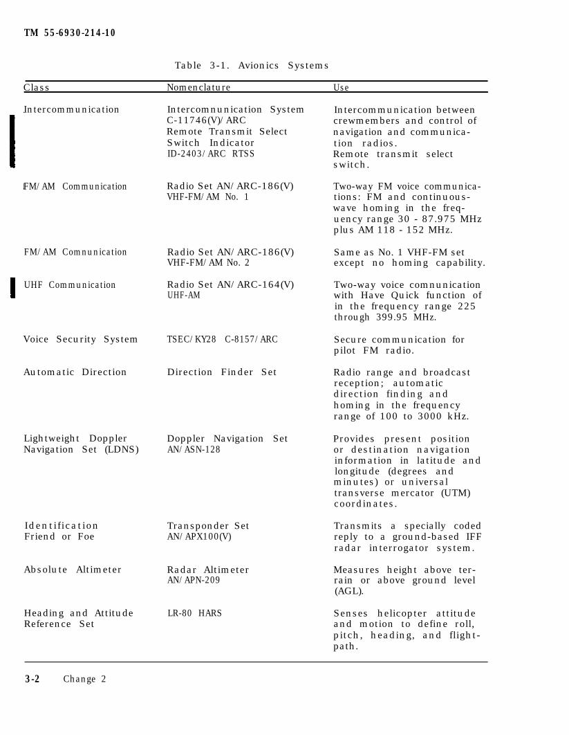
TM 55-6930-214-10
Table 3-1. Avionics Systems
Class Nomenclature Use
Intercommunication
FM/AM Communication
FM/AM Comnunication
UHF Communication
Voice Security System TSEC/KY28 C-8157/ARC
Automatic Direction Direction Finder Set
Lightweight DopplerNavigation Set (LDNS)
IdentificationFriend or Foe
Absolute Altimeter
Heading and AttitudeReference Set
C-11746(V)/ARCIntercomnunication System
Remote Transmit SelectSwitch IndicatorID-2403/ARC RTSS
crewmembers and control ofnavigation and communica-
Intercommunication between
tion radios.Remote transmit selectswitch.
Radio Set AN/ARC-186(V)VHF-FM/AM No. 1
Radio Set AN/ARC-186(V)VHF-FM/AM No. 2
Radio Set AN/ARC-164(V)UHF-AM
Doppler Navigation SetAN/ASN-128
Transponder SetAN/APX100(V)
Radar AltimeterAN/APN-209
LR-80 HARS
Two-way FM voice communica-tions: FM and continuous-wave homing in the freq-uency range 30 - 87.975 MHzplus AM 118 - 152 MHz.
Same as No. 1 VHF-FM setexcept no homing capability.
Two-way voice comnunicationwith Have Quick function ofin the frequency range 225through 399.95 MHz.
Secure communication forpilot FM radio.
Radio range and broadcastreception; automaticdirection finding andhoming in the frequencyrange of 100 to 3000 kHz.
Provides present positionor destination navigationinformation in latitude andlongitude (degrees andminutes) or universaltransverse mercator (UTM)coordinates.
Transmits a specially codedreply to a ground-based IFFradar interrogator system.
Measures height above ter-rain or above ground level(AGL).
Senses helicopter attitudeand motion to define roll,pitch, heading, and flight-path.
3-2 Change 2
CHAPTER 4
TM 55-6930-214-10
TACTICS
4-l . GENERAL. The CMS, having full mission tactical weapons capability, enablesthe pilot and/or CPG trainee to practice and improve proficiency in missionsinvolving missile and rocket delivery and gunnery exercises. The followingarmament systems and components are simulated and interfaced with the computer viasignal-conditioning equipment:
M-130 chaff dispenserVideo recorder system (VRS)
M-230E1 30-mm area weapon systemPoint target weapons system (Hellfire)Integrated helmet and display sight system (IHADSS)Optical relay tube (ORT)Pilot night vision system (PNVS)Aerial rocket control system (ARCS)Target acquisition and designation system (TADS)Laser rangefinder/designatorVideo display unit (VDU)APR-39 radar warning receiverALQ-136 radar jammerALQ 144 IR jammer
4-2. VISUAL SIMULATION. The simulated environment consists of out-the-windowdisplays for the pilot and CPG trainees with tactical targets in the visual scene.Scorable targets of opportunity are provided in the visual scene at selected loca-tions in the form of military vehicles or missile launching sites. The display alsoportrays such weapon effects as rocket and missile flightpaths, weapon burnout,target or ground impact. The sensor displays also present similar effects for thepilot and CPG trainees with appropriate field-of-view and sensor-sighting direc-tions. Reticles and symbology are included as necessary.
4-3. TRAINING. To initiate a problem, the pilot or CPG instructor can chooseselected targets as movable targets that will be displayed on the ORT or out thewindow. Velocity is under instructor control, and direction of the moving targetsis along predetermined pathways in the visual scene. Weapon loading is carried outby the instructor by means of IOS console CRT/keyboard action. There are 15different weapon loading configurations available. The current status of remainingarmament is presented on one of the IOS CRT status area and is based on the initialconditions of the weapon loading configuration and weapons previously fired.
4-4. EVALUATION. The instructor is provided with weapon scoring data on a CRTpage. The displayed data provides the number of rounds fired, hit/miss status, andmiss distances, displayed as distance, long or short, left or right, and high orlow, where applicable. The aural cue system provides for simulation of normal andabnormal sounds that make up the cockpit acoustic environment. Weapon soundsinclude: ARCS, Hellfire, and area weapon system 30-mm guns.
Change 2 4-1/(4-2 blank)

TM 55-6930-214-10
CHAPTER 5
OPERATING LIMITS AND RESTRICTIONS
5-1. GENERAL. The CMS has a high degree of similarity to the actual helicopter.Since the purpose of the CMS is for individual and crew proficiency and tacticaltraining, certain operations and functions of the aircraft are simulated onlypartially or not at all. Those operations and functions that follow weredetermined to have very low or no applicability for the enhancement of pilot andCPG training and proficiency. General items include the following:
Transparent canopy plexiglass is not presentCanopy removal arm/fire mechanisms are installed but nonfunctionalPilot lighting control panel is functional but limited
5-2. AVIONICS. Comnunications equipment provides for instructor and traineecommunications, but not actual signal reception or transmission. Discretefrequency radio communications channels are not available. (Additional limitationsthat exist with the avionics equipment are described in Chapter 3.)
5-3. TEMPERATURE AND HUMIDITY. The simulator compartments and motion systems arerequired to operate in a comfort-controlled environment at a temperature of 75(±10)OF (18.33 to 29.44OC) at a 50 (±5)% relative humidity. The computer complexis required to operate in a controlled environment of 70 (±5)OP (18.33 to 23.88OC)at a 50 (±5)% relative humidity.
a. In the course of operation, variations in room temperature must not result inthe development of relative humidity above 70% or below 30% at any temperature with-in the range from 50 to 100OF (10 to 38OC). Temperature sensors in the equipmentcabinets are capable of sensing two overheat temperatures. At 100OF (38OC). theyIlluminate a light on the failure indications panel indicating that a particularcabinet location is in an overheat condition. In addition, an aural warning isactivated. If the overheating condition is not corrected, the entire CMS complexis automatically shut down when the temperature exceeds 110OF (44OC).
b. The internal temperature of the pilot and CPG CMS compartments is controlledby separate, dedicated air conditioners ducted at supplementary outlets within thecompartment and the normal cockpit heating and defrosting ducts. Separate thermo-stat controls are provided on the inside rear wall of each compartment. The cock-pit air temperature controls, although present, are nonfunctional.
5-4. OCCUPANCY. During simulated maneuvers, safety reasons require that occupancyof each flight compartment is limited to three persons: the trainee, an instruc-tor, and an observer. Use of seat belts is mandatory while in motion.
5-5. MOTION SYSTEM. For multiaxis motion, the maximum platform excursion valuesare given below with respect to a forward reference point. These values aremeasured with respect to an origin established when the motion platform is con-sidered to be at a neutral position: that is, with the hydraulic cylinder legs atmidposition:
Vertical 33 inches up, 38 inches downLateral ±58 inchesLongitudinal ±53 inches
Change 2 5 -1
a. Environmental Conditions. Selections of environmental conditions are limitedas follows:
Barometric pressureOutside air temperature
Wind velocityWind directionVertical wind gustHorizontal wind gustTurbulence levelV i s ib i l i t yCeilingCloud topsScud cloudsRandom visibility
Icing enableHorizon glow
TM 55-6930-214-10
Pitch 31O down, 36O upRoll ±32O
Yaw ±32O
5-6. VISUAL SYSTEM. Two DIG systems are used in the CMS, differing only in thenumber of channels offered and in the hardware required related to that differ-ence. The same software is used for both DIG’s.
a. There are timing constraints or desired system performance to provide high-density scenes with DTV and FLIR images at a 60-Hz rate.
b. The DIG’s consist of a three-channel DIG system and a one-channel DIG sys-tem. The three-channel system provides either a three-channel out-the-window (OTW)display or pilot night vision sensor (PNVS) video. The one-channel system providessimulation of the three target acquisition and designation system (TADS) sensors:forward-looking infrared (FLIR), day TV (DTV), and direct-view optics (DVO). Sincethere are only two DIG systems, there are limitations on the number of visual dis-plays that can be viewed simultaneously. (Table 5-1 lists the displays availablein each cockpit during integrated or independent CMS operations.)
5-7. AUDIO SYSTEM. Once programmed, accompanying audio cannot be turned off whilea demonstration continues. Audio is not available during slow-time playback. A l laural cues are limited in loudness to within established safe levels of hearing.Sounds associated with rain and hail are not provided.
5-8. IOS CRT-CONTROLLABLE PARAMETERS. The CRT display pages provide instructorcontrol for aircraft environment, flight, and miscellaneous related parameters.Selectable values for edit are limited within the range normally found in arealistic world or within the limitations of the actual helicopter.
28 to 31 inches Hg-40OC to +62OC-40OF to +252OF0 to 30 knots in l-knot increments001 to 360 degrees in l-degree increments0 to 25 knots In 5-knot Increments0 to 25 knots in 5-knot increments0 to 5, 0 = off, 5 - max0 to 99,999 meters0 to 50,000 feet0 to 50,000 feetOn/offOn/off (available only with visibility
of 2000 meters or less)on/off0 to 5, 0 - off, 5 - max
5-2 Change 1
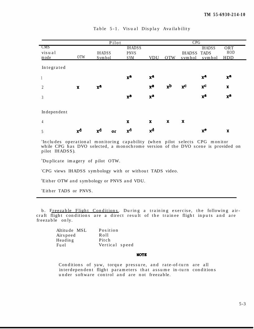
TM 55-6930-214-10
Table 5-1. Visual Display Availability
CMSvisualmode
P i lo t CPGIHADSS IHADSS ORT
IHADSS PNVS IHADSS TADS HODOTW Symbol SYM VDU OTW symbol symbol HDD
Integrated
1
2
3
Independent
4
5
aIncludes operational monitoring capability (when pilot selects CPG monitorwhile CPG has DVO selected, a monochrome version of the DVO scene is provided onpilot IHADSS).
bDuplicate imagery of pilot OTW.
cCPG views IHADSS symbology with or without TADS video.
dEither OTW and symbology or PNVS and VDU.
eEither TADS or PNVS.
b. Freezable Flight Conditions. During a training exercise, the following air-craft flight conditions are a direct result of the trainee flight inputs and arefreezable only.
Altitude MSL PositionAirspeed RollHeading PitchFuel Vertical speed
Conditions of yaw, torque pressure, and rate-of-turn are allinterdependent flight parameters that assume in-turn conditionsunder software control and are not freezable.
5-3
TM 55-6930-214-10
c. Editable Flight Conditions. Aircraft flight condition editable parametersare :
Fuel loadingPosition
2509 pounds maximum21s VK 8000500021s WK 2000500021s WK 2000820021s VK 80008200
d. Miscellaneous Conditions. Parameter limits for related conditions are:
Sound levelRunway lightsVASIAirbase culturalApproach lightsStrobeBeaconWeapon load number
0 - 5, 0 = o f f , 5 = max0 - 5, 0 = o f f , 5 = maxcm/off0 - 5, 0 = o f f , 5 = max0 - 5, 0 = o f f , 5 = maxon/offon/off1 - 15
5-9. COCKPIT CIRCUIT BREAKERS. Circuit breakers on the ac and dc circuit breakerpanels are functional and poppable.
5-10. ARMAMENT SYSTEM. Armament simulation is implemented so that the instructormust inform the trainee which weapon load configuration is in effect and thattrainee actions and indications must be compatible. In the aircraft, the backupbus controller assumes the task of providing weapons data if the fire controlcomputer (FCC) fails. In the simulator, the FCC is allowed to function and a warn-ing light canes on to indicate the function.
5-11. Deleted.
5-4 Change 2
TM 55-6930-214-10
5-12. INDEPENDENT MODE. This mode is limited as follows:
a. Demonstrations cannot be dynamically recorded.
b. Deleted.
c. Instructors/operators cannot initiate malfunctions affecting the othercockpit.
d. The CPG instructor ray select VISIONICS POINTING and REMOTE DESIGNATIONS forthe CPG.
e. AUTOFLY capability is available to the CPG cockpit.
f. The CPG has radio communications with the CPG instructor over the ICS, VHF,and UHF radios regardless of their operational status.
g. The CPG cannot affect electronic warfare threat environment.
h. Deleted.
5-13. INTEGRATED MODE. This mode is limited as follows:
a. CPG visual is the same as the pilot front visual.
b. Either pilot or CPG instructor may be selected as master instructor withcontrol and editing functions. The slave instructor has limited IOS control andediting functions. Selection of CRT page displays without edit, and motion off,emergency stop, freeze, timer reset, edit malfunctions, and hardcopy request areavailable to the other instructor. Master control can be assumed by or transferredto the other instructor at any time.
Change 2 5-5/(5-6 blank)

TM 55-6930-214-10
CHAPTER 6
VISUAL SYSTEM
6-1. GENERAL. The AH-64 CMS utilizes two digital image generation (DIG) systemsto provide the necessary visual displays. A computer-generated data base providesa tactical gaming area and an airfield area of approximately 1,200 square kilo-meters (32 x 40 km). The gaming area is a generic terrain representation that wasspecifically designed to meet the diverse training requirements related to attackhelicopter operations.
NOTE
Since these are only two DIG systems provided with the CMS,there are limitations on the number of visual displays that canbe viewed simultaneously. (Chapter 5 lists the displaysavailable in each cockpit during integrated or independent CMSoperations.)
a. Out-the-Window Displays. Each cockpit has three out-the-window displays(left, front, and right). In the independent mode, each cockpit requires the useof its DIG system to provide OTW scenes. In the integrated mode, one DIG providesOTW scenes to both cockpits but from the pilot’s perspective.
b. Sensor System Displays. The visual generation system has the capability ofproviding imagery to every sensor display in the CMS. These include the pilotIHADSS with PNVS and symbology, the OTW scene, and the VDU. The pilot can alsomonitor the CPG TV or TADS FLIR on the VDU during integrated flight training. TheCPG has displays for IHADSS and ORT heads-down display (HDD), plus heads-outdisplays (HOD) for TV and FLIR.
Change 1 6-1/(6-2 blank)

CHAPTER 7
TM 55-6930-214-10
NORMAL OPERATING PROCEDURES
Section I. CONTROLS AND INDICATORS
CAUTION
Due to abnormal shutdown possible hardware damage nay occur.
7-l. EMERGENCY STOP. Emergency stop switches are located on the various elec-tronic cabinets throughout the CMS complex and at the trainee stations. Theseswitches should not be used unless an actual emergency exists. Emergency stop,when depressed, removes facility power to the entire CMS complex, including themotion and visual systems.
a. The motion platform is returned to the settle position at the fastest prac-tical speed by a quick-settle control valve if emergency stop is activated.
b. Emergency stop switches are at the following locations:
Instructor/operator station (IOS) console control panelTrainee control panelLinkage cabinetMotion cabinetMotion pumpsPower cabinet
7-2. MAJOR MODE SELECT. Major mode select permits the instructor a choice of in-tegrated or independent training mode configurations for the CMS. In the inte-grated mode, both CMS cockpits are electronically coupled and provide a simulatedaircraft and environment for pilot and CPG training as a crew. The instructor canselect and designate from which IOS station to conduct and manage training. Thisdecision is based upon what the specific training objectives are for that trainingperiod. In the independent mode, each CMS cockpit is an independent simulated.aircraft, and training can be conducted in each cockpit without interfering withthe other cockpit.
a. Four switchlights on the left side of the IOS console control panel permitthe selection and designation of the major mode of operation and training config-uration for the CMS. (See figure 7-1.) The switchlights are IND, INTEG, PILOTINSTR MSTR, and CPG INSTR MSTR. The IND/INTEG switchlights are used to selecteither independent or integrated mode of operation. If integrated mode is select-ed, one IOS must be designated to be the master station (PILOT INSTR MSTR or CPGINSTR MSTR). The raster station has control of the CMS instructional features thatare used to establish and control the training process. When switching from inde-pendent to integrated, the master station function defaults to the CPG IOS.
b. The following characteristics are related to major mode selection:
(1) Rode changes must be requested while in problem freeze.
(2) When a mode change is initiated from independent to integrated or viceversa, an automatic master reset occurs; that is, all temporary modifications,TEE's, AMI’s, and IC’s are removed from the simulation.
Change 2 7 - l
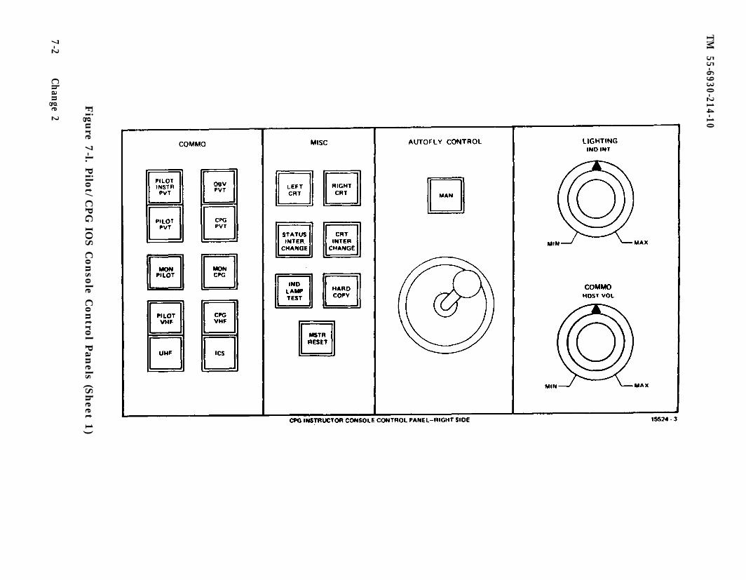
TM
55-6930-214-10
Figu
re 7-l. P
ilot/C
PG
IOS C
onso
le Contro
l Pan
els (Sheet 1
)
7-2C
hange 2
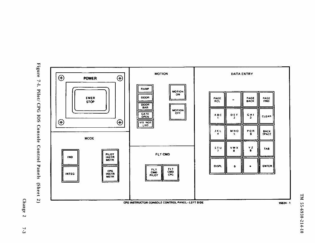
TM 55-6930-214-10
Figu
re 7-l. P
ilot/C
PG
IOS C
onso
le Contro
l Pan
els(S
heet 2
)
Change 2
7-3
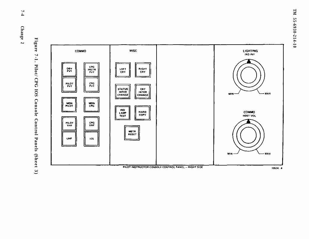
TM
55-6930-214-10
Figu
re 7-1
. Pilo
t/CPG
IOS C
onso
le Contro
l Pan
els (Sheet 3
)
7-4C
hange 2
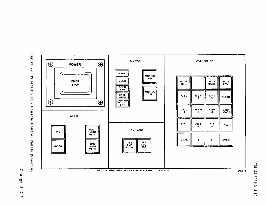
TM 55-6930-214-10
Figu
re 7-l. P
ilot/C
PG
IOS C
onso
le Contro
l Pan
els (Sheet 4
)Chan
ge 2
7-5
TM 55-6930-214-10
(3) During integrated mode. the following switches are active only at themaster IO station:
Condition storeCondition resetReplay resumeReplay flyoutReplay slow-timeFlight command pilotFlight command CPGMaster resetPilot instructor masterCPG instructor masterLeft CRTRight CRTStatus interchangeCRT interchange
master station only
refer to NOTE
Either IO can select the master IO function by depressing thePILOT INSTR MSTR or CPG INSTR MSTR switchlight.
(4) In integrated mode, demos are active only at the master station.
(5) For AMI and TEE preps, the CPG IOS station must be the master.
c. The MODE select switchlights are used to prepare the CMS for crew training,to select independent training for pilot and CPG, and to designate which IOS willbe the master station.
7-3. MOTION CONTROL. Motion controls are located on the IOS console control panel(figure 7-1) and the trainee control panel (figure 7-2). Incorporated with themotion control switchlights are a series of microswitch safety interlocks.
a. When the MOTION ON switchlight is depressed, the following microswitches mustbe closed for motion to come up:
Cockpit/instructor station entrance doorDoor barRampRight visual displayService gates to motion areasCabinet doors located on motion platformPressure pads on platform floor
b. The motion system immediately settles to a nonerect position if anymicroswitch interlock is opened during flight. The IOS console control panel hasinterlock warning lights to indicate any open switch during flight or before motionis activated.
7-4. FLIGHT COMMAND. The flight controls (cyclic, collective, and antitorque) ineach trainee cockpit are totally independent and separate systems. In the inde-pendent mode of training, each set of controls works as in two different aircraft,and the computer responds accordingly to their outputs. However, when the CMS is
7-6 Change 2
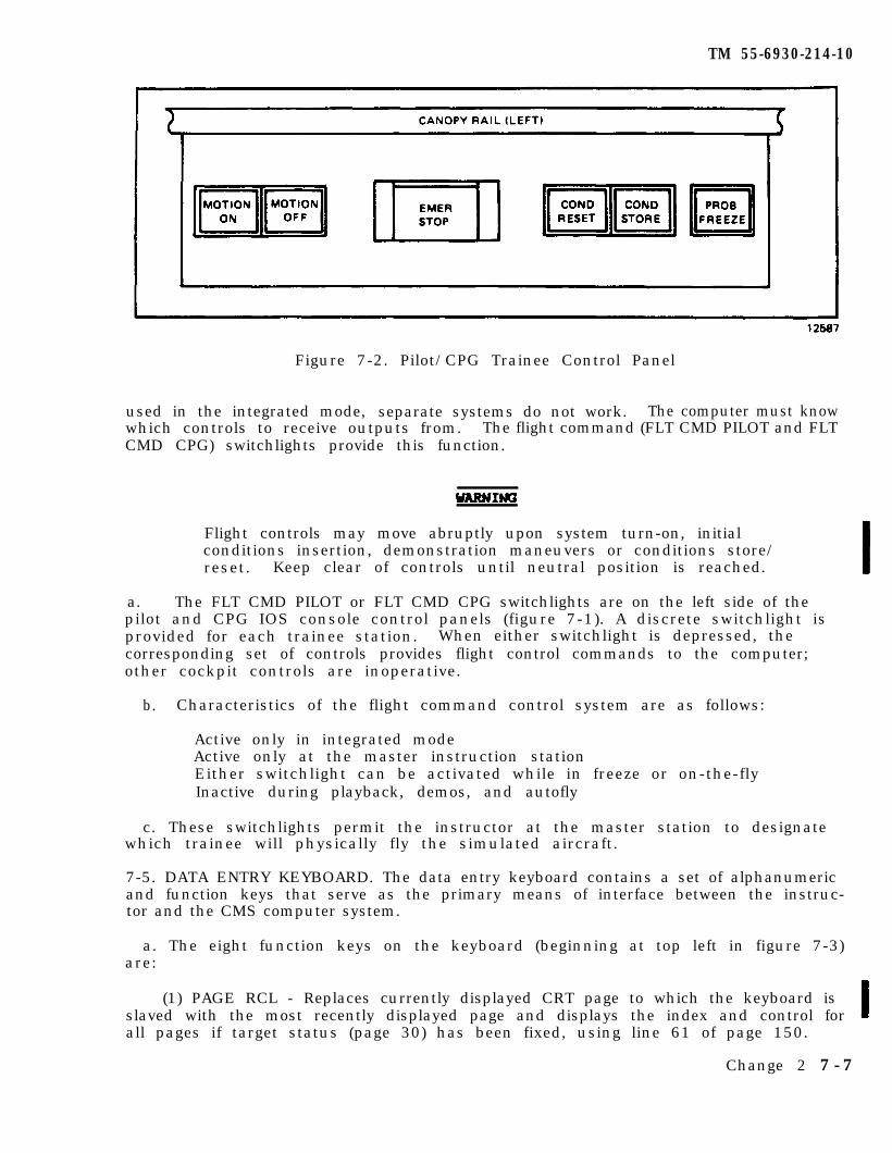
TM 55-6930-214-10
Figure 7-2. Pilot/CPG Trainee Control Panel
used in the integrated mode, separate systems do not work. The computer must knowwhich controls to receive outputs from. The flight command (FLT CMD PILOT and FLTCMD CPG) switchlights provide this function.
Flight controls may move abruptly upon system turn-on, initialconditions insertion, demonstration maneuvers or conditions store/reset. Keep clear of controls until neutral position is reached.
a. The FLT CMD PILOT or FLT CMD CPG switchlights are on the left side of thepilot and CPG IOS console control panels (figure 7-1). A discrete switchlight isprovided for each trainee station. When either switchlight is depressed, thecorresponding set of controls provides flight control commands to the computer;other cockpit controls are inoperative.
b. Characteristics of the flight command control system are as follows:
Active only in integrated modeActive only at the master instruction stationEither switchlight can be activated while in freeze or on-the-flyInactive during playback, demos, and autofly
c. These switchlights permit the instructor at the master station to designatewhich trainee will physically fly the simulated aircraft.
7-5. DATA ENTRY KEYBOARD. The data entry keyboard contains a set of alphanumericand function keys that serve as the primary means of interface between the instruc-tor and the CMS computer system.
a. The eight function keys on the keyboard (beginning at top left in figure 7-3)are:
(1) PAGE RCL - Replaces currently displayed CRT page to which the keyboard isslaved with the most recently displayed page and displays the index and control forall pages if target status (page 30) has been fixed, using line 61 of page 150.
Change 2 7 -7
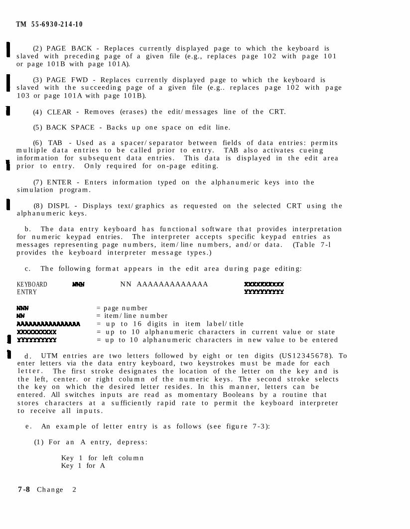
TM 55-6930-214-10
(2) PAGE BACK - Replaces currently displayed page to which the keyboard isslaved with preceding page of a given file (e.g., replaces page 102 with page 101or page 101B with page 101A).
(3) PAGE FWD - Replaces currently displayed page to which the keyboard isslaved with the succeeding page of a given file (e.g.. replaces page 102 with page103 or page 101A with page 101B).
(4) CLEAR - Removes (erases) the edit/messages line of the CRT.
(5) BACK SPACE - Backs up one space on edit line.
(6) TAB - Used as a spacer/separator between fields of data entries: permitsmultiple data entries to be called prior to entry. TAB also activates cueinginformation for subsequent data entries. This data is displayed in the edit areaprior to entry. Only required for on-page editing.
(7) ENTER - Enters information typed on the alphanumeric keys into thesimulation program.
(8) DISPL - Displays text/graphics as requested on the selected CRT using thealphanumeric keys.
b. The data entry keyboard has functional software that provides interpretationfor numeric keypad entries. The interpreter accepts specific keypad entries asmessages representing page numbers, item/line numbers, and/or data. (Table 7-lprovides the keyboard interpreter message types.)
c. The following format appears in the edit area during page editing:
KEYBOARD NN AAAAAAAAAAAAAENTRY
= page number= item/line number= up to 16 digits in item label/title= up to 10 alphanumeric characters in current value or state= up to 10 alphanumeric characters in new value to be entered
d. UTM entries are two letters followed by eight or ten digits (US12345678). Toenter letters via the data entry keyboard, two keystrokes must be made for eachletter. The first stroke designates the location of the letter on the key and isthe left, center. or right column of the numeric keys. The second stroke selectsthe key on which the desired letter resides. In this manner, letters can beentered. All switches inputs are read as momentary Booleans by a routine thatstores characters at a sufficiently rapid rate to permit the keyboard interpreterto receive all inputs.
e. An example of letter entry is as follows (see figure 7-3):
(1) For an A entry, depress:
Key 1 for left columnKey 1 for A
7-8 Change 2
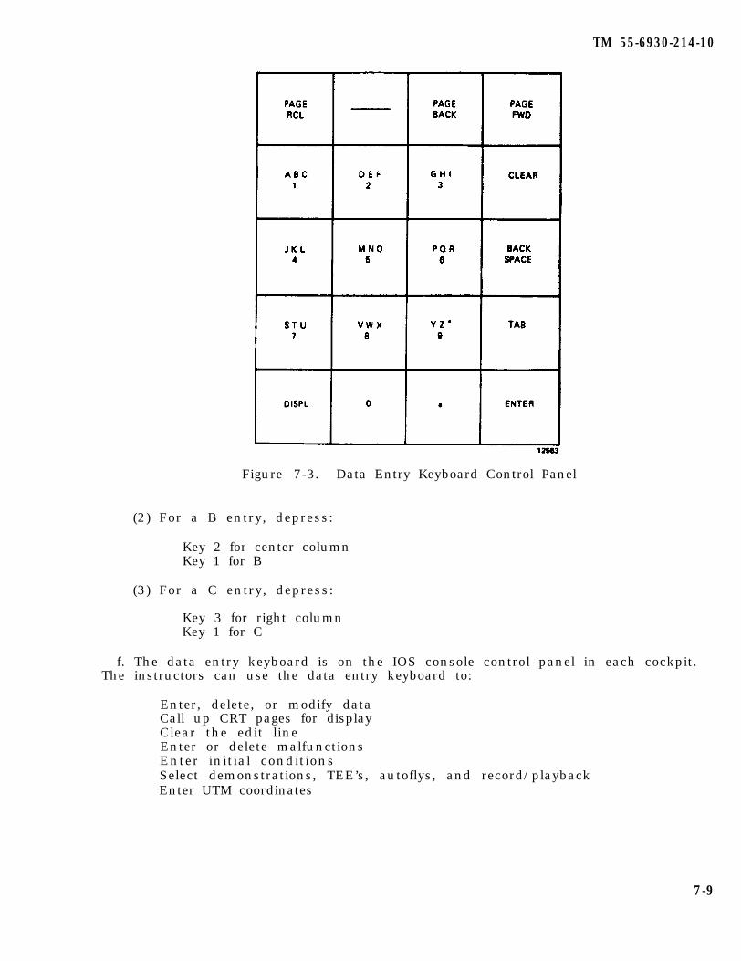
TM 55-6930-214-10
Figure 7-3. Data Entry Keyboard Control Panel
(2) For a B entry, depress:
Key 2 for center columnKey 1 for B
(3) For a C entry, depress:
Key 3 for right columnKey 1 for C
f. The data entry keyboard is on the IOS console control panel in each cockpit.The instructors can use the data entry keyboard to:
Enter, delete, or modify dataCall up CRT pages for displayClear the edit lineEnter or delete malfunctionsEnter initial conditionsSelect demonstrations, TEE’s, autoflys, and record/playbackEnter UTM coordinates
7-9
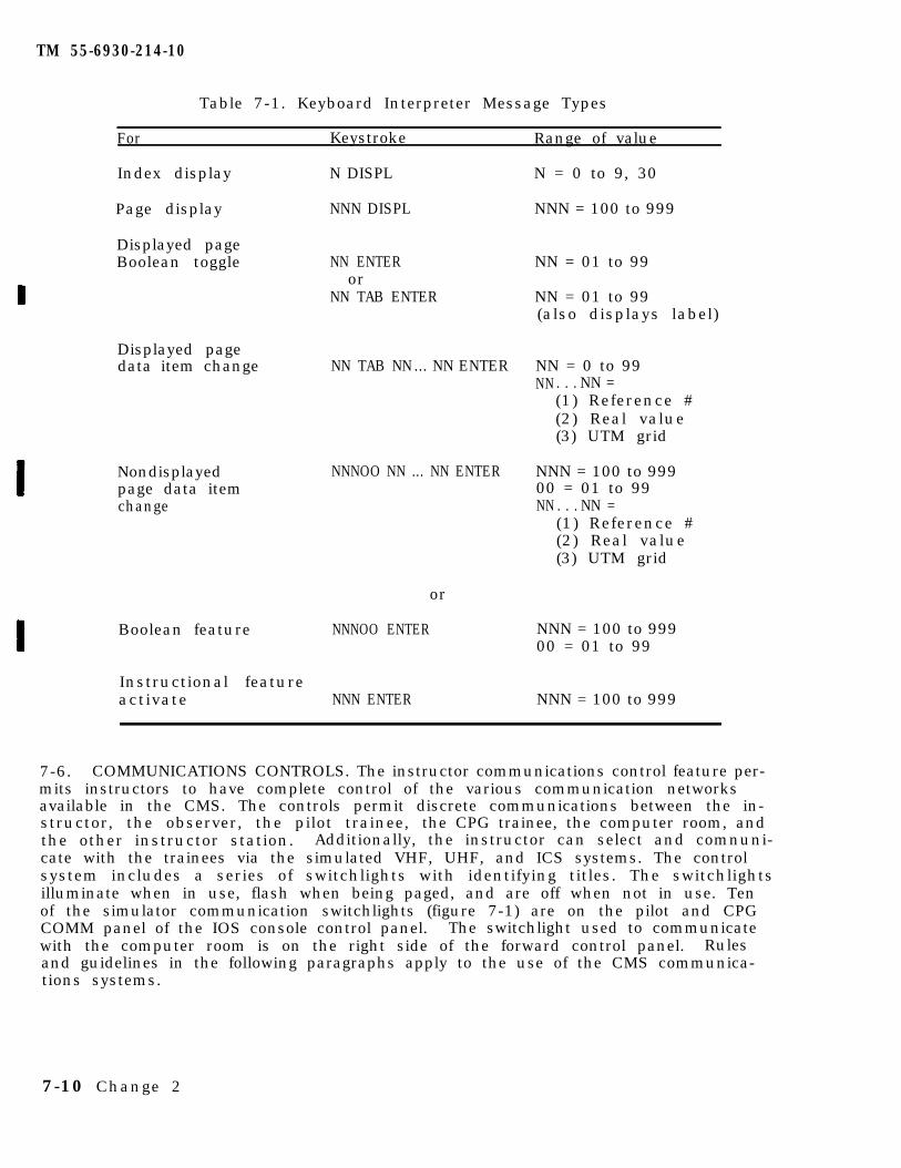
TM 55-6930-214-10
Table 7-1. Keyboard Interpreter Message Types
For Keystroke Range of value
Index display
Page display
Displayed pageBoolean toggle
N DISPL
NNN DISPL
NN ENTERor
NN TAB ENTER
Displayed pagedata item change
Nondisplayedpage data itemchange
NN TAB NN... NN ENTER
NNNOO NN ... NN ENTER
Boolean feature
or
NNNOO ENTER
Instructional featureactivate NNN ENTER
N = 0 to 9, 30
NNN = 100 to 999
NN = 01 to 99
NN = 01 to 99(also displays label)
NN = 0 to 99NN . . . NN =
(1) Reference #(2) Real value(3) UTM grid
NNN = 100 to 99900 = 01 to 99NN . . . NN =
(1) Reference #(2) Real value(3) UTM grid
NNN = 100 to 99900 = 01 to 99
NNN = 100 to 999
7-6. COMMUNICATIONS CONTROLS. The instructor communications control feature per-mits instructors to have complete control of the various communication networksavailable in the CMS. The controls permit discrete communications between the in-structor, the observer, the pilot trainee, the CPG trainee, the computer room, andthe other instructor station. Additionally, the instructor can select and comnuni-cate with the trainees via the simulated VHF, UHF, and ICS systems. The controlsystem includes a series of switchlights with identifying titles. The switchlightsilluminate when in use, flash when being paged, and are off when not in use. Tenof the simulator communication switchlights (figure 7-1) are on the pilot and CPGCOMM panel of the IOS console control panel. The switchlight used to communicatewith the computer room is on the right side of the forward control panel. Rulesand guidelines in the following paragraphs apply to the use of the CMS communica-tions systems.
7-10 Change 2
TM 55-6930-214-10
a. Instructor Private Communications (PILOT/CPG INSTR PVT, OBV PVT). Thefollowing criteria apply:
(1) Instructors can call and communicate with the other instructor or withtheir own observer.
(2) Either observer can call and communicate with either instructor.
(3) When a call is initiated by a keypress, the caller switchlight and thecalled party switchlight identifying the caller both flash.
(4) The flashing light is terminated by:
(a) The caller pressing the same switchlight.
(b) The caller selecting another interlocked switchlight.
(c) The called party answering the call by pressing the flashing switchlight.
(5) When the called party answers the call by pressing the flashing switch-light, both the caller switchlight and the called party switchlight are litsteadily, and a communications path between them is established. Actuation ofpush-to-talk switches on the headset cord is required to enable the audio gates.
(6) The lights are extinguished and communications terminated by:
(a) The caller pressing the same switchlight.
(b) The caller selecting another interlocked switchlight.
(c) The called party deselecting the call by pressing the caller switchlight.
(d) The called party initiating another call on an interlocked switchlight.
(7) The instructor (PILOT INST PVT or CPG INST PVT) PRIVATE COMM is functionalin integrated and independent mode.
b. Trainee Private Communications (PILOT PVT, CPG PVT). The following criteriaapply:
(1) Either instructor can selectively communicate with either trainee.
(2) Private communications to trainees is operational in integrated andindependent mode.
(3) The trainee PRIVATE COMM (PILOT PVT or CPG PVT) is an override function.The instructor can communicate with the trainee regardless of traineecommunications configuration.
(4) The instructor selects the desired trainee private communicationsswitchlight. The pertinent switchlight is then lit steadily, and a private commu-nications path to the trainee is enabled. Hot-mic operation is used.
7-11
TM 55-6930-214-10
(5) The instructor deselects trainee private communications by:
(a) Pressing the same switchlight.
(b) Selecting another interlocked switchlight.
c. Trainee Monitor (MON PILOT, MON CPG). The following criteria apply:
(1) In integrated mode, either instructor and either observer can monitorpilot or CPG communications.
(2) In independent mode:
(a) Both the pilot instructor and the pilot observer can monitor pilotcommunications.
(b) Both the CPG instructor and CPG observer can monitor CPG communications.
(3) An instructor or observer initiates the monitor function by pressing theassociated switchlight on the IOS COMM control panel. The selected switchlight islit steadily, and the pertinent trainee headset audio is gated to the monitor inputin the instructor or observer audio system.
(4) The light is extinguished and the audio monitor terminated when theinstructor or observer presses the monitor switchlight that is lit.
d. Radio Communications (PILOT VHF, CPG VHF, UHF). The following criteria apply:
(1) In integrated mode:
(a) Either instructor can communicate with either trainee over one of thetwo ARC-186 (VHF) or over the ARC-164 (UHF), provided the sets are operational. Aradio set is operational if the set and either ICS COMM box are powered up.
(b) The instructor initiates a call to a trainee by depressing the XMIT(VHF, UHF) switchlight associated with the desired communications set.
(c) If the set is operational, the switchlight is lit, and the instructormic audio is gated to the proper simulated radio receiver. Actuation of theinstructor push-to-talk transmit switch is required.
(d) A trainee initiates a call on the desired set by configuring the cockpitset and COMM box properly and keying the press-to-talk switch.
(e) If the set is operational, the associated switchlight on both IOS COMMpanels flash. Trainee-to-instructor call audio is always enabled.
(f) The flashing light is terminated by:
1 The trainee releasing the press-to-talk switch.
2 Either instructor pressing the flashing XMIT (PILOT VHF or CPG VHF,PILOT UHF or CPG UHF) switchlight.
7-12
TM 55-6930-214-10
(g) The instructor who pressed the flashing XMIT switchlight sees the lightbecome steady, and mic audio is gated to the proper simulated radio receiver.
(h) Subsequent press-to-talk actuations by the trainee while transmitting onthat particular radio set do not cause flashing of the XMIT switchlight of that setat either IOS COMM panel.
(i) After one instructor has elected to answer the call, the other IOS XMITswitchlight neither flashes nor lights. Audio over the particular radio set is notenabled for the inactive instructor.
(j) The second instructor can get in the loop by selecting the same radioset XMIT switchlight on the COMM panel.
(k) If both instructors are in the loop, one can disengage from the loopwithout deselecting the whole loop.
(1) At the disengaged IOS, the light is extinguished, and audio for thatradio set is disabled.
(m) Radio communication is terminated by the last instructor in the loop by:
1 Pressing the radio set XMIT switchlight.
2 Selecting another interlocked switchlight.
(2) In independent mode:
(a) The pilot instructor can communicate with the pilot trainee over thepilot ARC-186 (VHF) or ARC-164 (UHF) if the sets are operational, and over the CPGARC-186 (VHF) regardless of its operational status.
(b) The CPG instructor can communicate with the CPG trainee over the CPGARC-186 (VHF) if the set is operational, and over the pilot ARC-186 (VHF) andARC-164 (UHF) regardless of their operational status.
(c) The instructor initiates a call to a trainee by depressing the XMITswitchlight associated with the desired communications set. Actuating the transmitswitch completes the transmission loop.
(d) The switchlight is lit, and the instructor mic audio is gated to theproper simulated radio receiver:
1 If the selected radio set is operational where it is required to beoperational.
2 If the selected radio set is to be used regardless of operational status.
(e) A trainee initiates a call on the desired set by configuring the cockpitset and COMM box properly and keying the press-to-talk switch.
(f) When the operational requirements for the set are met, the associatedswitchlight on the respective IOS COMM panel flashes. Trainee-to-instructor callaudio is always enabled.
7-13
TM 55-6930-214-10
(g) The flashing light is terminated by:
1 The trainee releasing the press-to-talk switch.
2 The instructor pressing the flashing XMIT switchlight.
(h) When the instructor presses the flashing XMIT switchlight, it becomessteadily lit, and mic audio is gated to the proper simulated radio receiver.
(i) Subsequent press-to-talk actuations by the trainee on that particularradio set do not flash the switchlight while it is selected.
(j) Radio communication is terminated when the instructor:
1 Presses the radio set XMIT switchlight.
2 Selects another interlocked switchlight.
e. Intercommunications System (ICS) Communications. The following criteriaapply:
(1) In integrated mode:
(a) Instructors, observers, and trainees can all communicate via the inter-communication system (ICS), provided the sets are operational. Trainee sets arepowered separately.
(b) Instructors and observers enter the system by pressing the ICS switch-lights.
(c) When either ICS set is operational, the selected switchlight is lit, andcaller mic audio is gated to the simulated ICS whenever the transmit switch isactuated.
(d) When a trainee transmits on an operational ICS set, the ICS switchlighton both instructor and both observer COMM panels flash. Trainee-to-instructor callaudio is always enabled.
(e) The flashing light is terminated by:
1 The trainee releasing the press-to-talk switch.
2 An instructor or an observer pressing the flashing ICS switchlight.
(f) The instructor or observer who pressed the flashing ICS switchlight seesthe light become steady, and mic audio is gated to the simulated ICS.
(g) Subsequent press-to-talk actuations by the trainee while transmitting onthe ICS do not cause flashing of the ICS switchlight on any IOS or observer COMMpanel.
(h) After a call has been answered, the ICS switchlights at the other COMMpanels neither flash nor light. ICS audio is enabled only for the instructor orobserver who has selected ICS.
7-14
TM 55-6930-214-10
(i) Any instructor or observer can enter the loop by pressing the ICSswitchlight.
(j) If more than one instructor or observer are in the loop, any one candisengage from the loop without deselecting the whole loop.
(k) When ICS is deselected, the light is extinguished and ICS audio is dis-abled.
(1) ICS communication is terminated by the last instructor or observer inthe loop by:
1 Pressing the ICS switchlight.
2 Selecting another interlocked switchlight.
(2) In independent mode:
(a) The pilot instructor, pilot observer, and pilot trainee can communicateon the ICS, provided the pilot ICS is operational.
(b) The CPG instructor, CPG observer, and CPG trainee can communicate on theICS, provided the CPG ICS is operational.
(c) The effects of instructor, observer, or trainee switchlight selectionsand transmissions are as in integrated mode, except that such effects are confinedto each cockpit.
f. Computer Room Communications. The following criteria apply:
(1) The instructors can each communicate with computer area personnel, andvice versa.
(2) The COMP ROOM CALL switchlight on the IOS forward control panel (figure7-4) is not interlocked with the other switchlights on the IOS console controlpanel. This allows instructor communications to the computer area even while incommunication with a trainee or another instructor.
(3) When an instructor presses the COMP ROOM CALL switchlight, the switch-lights on the IOS COMM panel and on the computer room audio control panel flash anda chime sounds in the computer area.
(4) Computer room personnel can call either instructor by pressing the corres-pondingly identified switchlight on the computer roan audio control panel.
(5) When this happens, the COMP ROOM CALL switchlight at the COMM panel of thedesired instructor, as well as the switchlight on the computer room audio controlpanel, flashes.
(6) The flashing lights are extinguished if the caller presses the switchlightagain.
(7) The flashing lights become steadily lit when the called party answers bydepressing the flashing switchlight. A communications path between them is thenestablished.
7-15
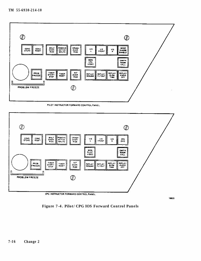
TM 55-6930-214-10
Figure 7-4. Pilot/CPG IOS Forward Control Panels
7-16 Change 2
TM 55-6930-214-10
(8) Lights are extinguished at both panels at the termination of a call; thatis, when either the caller or the called party presses the switchlight. Communica-tions are then disabled.
7-7. HARDCOPY. A hardcopy unit at each IOS can be accessed through a HARDCOPYswitchlight on the pilot and CPG console control panels (figure 7-1). The unitaccepts up to five requests for copy in rapid succession. The hardcopy unit isused to provide a copy of perishable information displayed on the selected CRT; toaid the instructor in subsequent review of trainee performance; and to provideobjective information for permanent records. Use of the hardcopy feature does notaffect any aspect of the simulation except for the generation of the copy. Thisfeature can be used independently of other instructional activities in progress.
7-8. LEFT CRT/RIGHT CRT. These switchlights allow the keyboard to be assigned tothe left or right CRT respectively for page control, data entry, and hard copy.
7-8.1 STATUS INTERCHANGE. Status interchange allows for the selectable switchingof the status pages between the two CRTs.
7-8.2 CRT INTERCHANGE. CRT interchange allows for the selectable switching of themain page area and index and control page areas together between the two CRTs.
7-9. INDICATOR LAMP TEST. There is one indicator lamp test switchlight on theconsole control panel (figure 7-1) at each IOS. When depressed at either IOS, thisswitchlight causes the illumination of all lamps on the console control panel andforward control panel at the respective IOS.
7-10. MASTER RESET. A master reset switchlight is located in the miscellaneoussection of the console control panel (figure 7-1) at each IOS. The master reset,when depressed, deletes all temporary modifications to the simulation (e.g., allTEE’s. AMI’s, and IC’s).
7-11. CPG AUTOFLY CONTROL. These controls are used to manually control headingand altitude of the CPG trainer during target engagement activities and weaponsfiring in the autofly mode of operation.
Change 2 7-17
TM 55-6930-214-10
a. The MANUAL switchlight on the console control panel allows the instructor tohave manual control at hover points, to allow the CPG trainee more time to completefiring activities. Control of heading and altitude is accomplished by the use of a4-direction joystick. Heading is accomplished by left or right movement, and alti-tude is changed by moving the joystick forward for up and backward for down.
b. Manual control can be activated any time prior to arrival, or while at a pre-selected hover location. This feature can be used to extend the period that theaircraft is unmasked beyond that which was originally recorded.
c. These controls are on the right side of the console control panel (figure7-l) at the CPG IOS only.
7-12. LIGHTING CONTROL. This control varies intensity of switchlights on bothcontrol panels.
7-13. HEADSET VOLUME CONTROL. The headset volme control is a multipositionpotentiometer located on each console control panel (figure 7-1). When this poten-tiometer is turned fully counterclockwise it allows minimum volume to the respec-tive headset, and when turned fully clockwise it allows maximum volume to therespective headset.
7-14. STORE/RESET CURRENT CONDITIOUS. The store/reset (S/R) current conditionsfeature permits the CMS to be returned rapidly to a previously encountered set ofsimulated conditions. When activated, the store function places the current flightconditions into memory (temporary memory) for subsequent recall or reset. Only oneset of conditions can be stored at any one time with this feature. The reset func-tion returns (resets) the CMS to the flight conditions that existed at the time thestore function was activated.
a. Controls for the S/R feature are on the forward control panel (figure 7-4) ateach IOS and on the trainee control panel (figure 7-2) on the left side of eachtrainee cockpit. The store function can be used any time in or out of freeze. Thereset function, however, can be accessed only while the CMS is In freeze.
b. Instructors can use the store reset current conditions function to enablerapid and easy reestablishment of the exact condition needed for a particular in-structional activity, and to provide access to a modified IC set without having torepeat the modification process.
c. If no current conditions have been stored during a training period, activa-tion of the reset function returns the CMS to the most recently selected IC set.Selection of a new IC set automatically replaces any stored conditions.
d. If desired or required, a set of stored conditions can be either displayed,hardcopied, or saved as a temporary IC set. The following procedures will permitthe instructor to:
(1) Display:
(a) Place the simulator in problem freeze.
(b) Activate RESET.
7-18
TM 55-6930-214-10
(c) When flashing FREEZE light ceases, call up and display CC page 150.
(2) Hardcopy:
(a) Display CC page 150 on IOS CRT.
(b) Depress HARDCOPY switchlight on console control panel.
(3) Save as an IC set:
(a) After RESET is activated and flashing FREEZE ceases, call up and displayany IC set.
(b) Use command lines 53 and 54 to save the set of conditions as a temporaryIC set at that IC set number. This temporary IC set is retained until amaster reset is activated.
7-15. MALFUNCTION CONTROLS. There are two switchlight keys on the forward controlpanel (figure 7-4) associated with malfunction control, MALF OVERRIDE and REMOVEACTIVE MALFS.
a. MALF OVERRIDE can be used to delete an impending AMI during the 10-secondalert period before it is actually activated. This AMI is disabled for theduration of the training period and does not affect the remaining malfunctions inthat AMI set. However, the overridden AMI can be manually inserted via the manualmalfunction pages and the data entry keyboard.
b. REMOVE ACTIVE MALFS can be used to delete all active malfunctions, eithermanual or automatic, from the simulation.
7-16. CRASH/HIT OVERRIDE. The CRASH/HIT OVERRIDE feature freezes or suspends on-going simulated activity when predetermined conditions are met. The effects uponthe simulation and upon the cockpit and IOS controls of an automatically initiatedfreeze are identical to those of a manually initiated freeze. The purpose of theautomatic freeze (AF) feature is to place the simulator in freeze immediately uponthe occurrence of specified events, and to do so without intervention by theinstructor, observer, or trainee.
a. Three kinds of events can trigger an automatic freeze:
(1) Entering a set of flight conditions that would be the equivalent of acrash (e.g., exceeding aircraft structural limits or impacting the surface at anexcessive rate).
(2) Being impacted by sufficient hits from threat weapons (and the malfunc-tions associated with such hits) that crash conditions result.
(e.g., preparing the simulator for an initial instructional activity or reaching(3) Encountering conditions that mandate placing the simulator In freeze
the end of a period of recorded flight, i.e., DEMOS, AUTOFLY, PLAYBACK).
b. Since the initiation of a freeze condition resulting from such events may notbe expected, its onset is called to the attention of the instructor via a flashingPROB FREEZE switchlight, symbology on MAP pages, and an alert message appearing inthe CRT alert block.
7-19
TM 55-6930-214-10
c. The simulator can be released from freeze by insertion of a new IC set or de-pressing HIT OVERRIDE. However, in the case of an automatically initiated freezeresulting from the entry of the simulated aircraft into crash conditions, actionmust be taken to remove or overcome those conditions before the period of freezecan be ended. This can be done while the simulator is in freeze by selecting andinserting a new set of initial conditions preparatory to beginning a new trainingactivity, thus effectively removing the aircraft from the conditions that led tothe freeze. Alternatively, the instructor can elect to override the crash condi-tions and permit the flight to continue from the point of crash. When this alter-native is selected, the simulated aircraft flies out of the crash conditionsfollowing termination of freeze.
d. In addition to standard crash conditions, automatic initiation of freezeoccurs when the simulator threat-scoring algorithm determines that the simulatedaircraft has received a sufficient number of rounds from an enemy weapon that air-craft systems are degraded to the point where an emergency landing is required andthat landing is unsuccessful. When this occurs, the simulator enters the freezestate automatically and remains in that state until it is ended by removing themalfunctions. The instructor can also elect in advance to override the malfunc-tions associated with the threat algorithm in order to avoid frequent forced land-ings for an unskilled pilot. This is accomplished by engaging HIT OVERRIDE. WhenHIT OVERRIDE is engaged, the effects of being hit, except aircraft degradation,occur (e.g., sounds and weapons signatures). Scoring and status information isdisplayed at the IOS. However, the aircraft continues to be flyable. The in-structor can elect to override or not override hit or crash conditions.
e. Other events that automatically initiate freeze relate to administrative as-pects of the simulator instructional process and provide an interruption in thesimulation at points at which a decision must be made concerning the next instruc-tional activity. No automatic freeze override function is appropriate with respectto these events, because their occurrence indicates a choice point at which a dif-ferent activity must be initiated if the simulation is to continue. Such an eventoccurs when the simulator is initially made ready for use at the beginning of aperiod of instruction and at the end of a segment of recorded flight (e.g., uponcompletion of a demonstration or a selected interval of record/playback).
f. Controls for CRASH OVERRIDE and HIT OVERRIDE are alternate-action switch-lights on the IOS forward control panels (figure 7-4). These switchlights are usedto prevent crash conditions, override a crash condition, and prevent aircraft sys-tems degradation due to hits.
7-17. INSTRUCTOR VISUAL CONTROL. All controls for monitoring of the visual systemsare on the right side of the forward control panel (figure 7-4). These switch-lights allow the instructors to monitor different types of displays depending onthe mode of operation.
monitor.
a. VIS L, VIS FRONT, and VIS R Switchlights. These switchlights allow the in-structor to select the desired OTW display to be viewed on the overhead DVO/OTW
b. Unique CPG IOS Switchliqhts. The following switchlights are at the CPG IOSonly:
7-20 Change 2
TM 55-6930-214-10
map displays.
(2) CPG DVO allows the CPG instructor to monitor the CPG DVO display when itis being employed.
(1) MON PILOT VIDEO (active in the integrated mode only) allows the CPG in-structor to view the current sensor system field of view being used by the pilot on
c. Unique Pilot IOS Switchlights. The following switchlights are at the pilotIOS only:
(1) MON CPG VIDEO (active in the integrated mode only) allows the pilot in-structor to view the current sensor field of view system being used by the CPG onnap displays.
(2) INDEP IHADSS ENABLE allows the pilot instructor to activate, but not moni-tor, the IHADSS in the independent mode only. This switchlight does not operate inthe integrated mode of operation.
7-18. MANUAL FREEZE. Manual freeze (MF) enables the instructor or the trainee tofreeze or suspend ongoing simulated activity. During the period of suspension, thesimulated conditions existing at the onset of MF are preserved, and the suspendedactivity can be resumed at the option of the instructor or the trainee. Except forthe primary flight controls, controls and displays at the IOS and in the cockpitretain their normal function during use of this feature and can be used to changethe preserved conditions. During a period of freeze, cockpit avionics displaysreflect the fixed position of the simulated aircraft, but otherwise functionnormally in response to operation of the controls associated with such displays.
a. The primary purpose of the MF feature is to permit interruption of the simu-lation so that other instructional or supporting activities can take place or toprovide a break in the instruction. The secondary purpose of this feature is toprovide a stable condition during periods in which the CMS is on but the cockpitcan be unoccupied; thus allowing necessary setup or simulation modification func-tions to be performed through controls at the IOS. Cockpit ingress/egress also ispossible during periods of freeze without concern for inadvertent movement of cock-pit controls.
b. Controls for manual freeze are on the forward control panel (figure 7-4) ofeach IOS and on the trainee control panel (figure 7-2) of each cockpit. In the in-tegrated mode of operation, activation of the freeze control in either cockpit sus-pends activities in both cockpits. In independent mode of operation, activation ofthe freeze control in one cockpit has no effect on the other cockpit.
c. The manual freeze function is used to:
Temporarily interrupt an ongoing training activity to critique performanceReposition the CMS for another instructional activityPreserve Perishable CRT data while hardcopy is being usedEffect changes in the simulationAccess other instructional features
d. A modification to the simulation that involves a discontinuity in any para-meter affecting flight can be made only while the simulator is in a freeze state(e.g., repositioning of the simulated aircraft or substituting one external visualdisplay scene for another). Discontinuities involving visual displays require that
Change 2 7-21
TM 55-6930-214-10
such displays be blanked to minimize distractions to the pilot. Instructional fea-tures that are incompatible with simulated flight under pilot control can be ini-tiated only when the simulator is in a freeze state (e.g., record/playback and de-monstration). Likewise, use of the hardcopy feature when simultaneous copies ofmultiple displays are desired, can occur only when the simulator is in freeze. Useof other features, such as malfunction simulation, automatic malfunction insertion,and parameter freeze, can be initiated without respect to the freeze status of thesimulator, but the effect of these features upon the simulation is noted only whenthe simulation resumes.
7-19. ELAPSED-TIME CLOCK (TIMER). The elapsed-tire clock is a digital displaythat, when activated, displays real-time in minutes and seconds. A discrete timerand controls are provided for each instructor. The timer can be operated indepen-dently at each IOS except during periods of the blinking PROBLEM FREEZE switchlight( i . e . , except during periods of reset or changing simulator conditions).
a. The timer digital display is located in the upper left-hand corner of themain page area on one of the IOS CRTs. It is permanently displayed during trainingand remains so even during page changes. Zero minutes and zero seconds (00:00) aredisplayed until the timer is activated. Controls to operate the timer are on theforward control panel (figure 7-4). A discrete switchlight is used to start andstop the timer action. When activated (TIMER START/STOP depressed), the displaycounts real-time in seconds and minutes. When depressed again (TIMER START/STOP),the display maintains the last digits in a freeze state. When depressed again, itactivates the display, and displayed time is cumulative. Additionally, A TIMERRESET switch, when depressed, resets the minutes and seconds to zero.
b. The instructors use the timers to determine elapsed problem time, to relateerrors to problem time, and to relate training events/activities to problem time.
7-20. REPLAY CONTROL. Four switchlights associated with the playback mode ofoperation are located in the lower right corner of the forward control panel(figure 7-4). The switchlights operate as follows:
a. REPLAY RESUME allows the instructor to freeze the playback at any point andselect RESUME. When selected, the simulator resets to the starting point of play-back activation and permits training to continue from that point. When initiated.the REPLAY RESUME switchlight illuminates, and the PROBLEM FREEZE switchlightflashes until initialization is complete and reset discrepancies have been cleared.
b. REPLAY FLYOUT allows the instructor to freeze the playback at any Point andselect FLYOUT. When selected, training can continue from that point in theplayback operation.
c. REPLAY SLOW TIME allows the instructor to slow the playback down, to allowmore time for the trainee to grasp important relationships between control inputsand resulting instrument indications, aircraft attitude, and system performance.slow-time playback takes twice as long to occur as real-time playback. There is noaudio communications replay during slow-time playback.
d. REPLAY AUDIO OFF allows the instructor to turn audio on or off any timeduring real-time playback.
7-22 Change 2
TM 55-6930-214-10
7-21. INSTRUCTORS MONITORS. The instructor video monitor is a color CRT that per-nits instructors to monitor selectively any of the three out-the-window (OTW) vis-ual displays or the CPG direct view optics (DVO) display. The only time a videosignal is available to monitor with this CRT is when the CMS is being operated inintegrated mode with visual mode 2 (OTW & DVO), in pilot independent lode withvisual mode 5, or CPG independent mode with visual mode 4. (Refer to table 7-2).
a. The instructor video monitor is above the data graphic display CRT at theIDS. (See figure 2-2). There is a power ON/OFF switch on the monitor. Controlsto select the visual display to be monitored are on the forward control panel. Thepilot instructor has three switchlights, VIS L, VIS FRONT, and VIS R, (figure 7-4)for selection of the left, front, or right visual display. The CPG instructor hasfour witchlights, VIS L, VIS FRONT, VIS R, and CPG DVO (figure 7-4). for selectionof the left, front, right, or DVO visual display.
b. The instructor can use the video monitor to selectively monitor either thepilot or CPG OTW field-of-view and to monitor DVO when the CPG trainee is employingthat system.
CMSvisualmode
Table 7-2. Visual Monitor Display Modes
Pi lo t CPGIHADSS IHADSS ORT
IHADSS PNVS IHADS TADS HODOTW symbo1 symbol VDU OTW symbol symbol HDD
Integrated
1
2
3
Independent
4
5
aIncludes operational monitoring capability (when pilot selects CPG monitor whileCPG has DVO selected, a monochrome version of the DVO scene is provided on pilotIHADSS).
bDup1icate imagery of pilot OTW.
cCPG views IHADSS symbology with or without TADS video.
dEither OTW and symbology or PNVS and VDU.
eEither TADS or PNVS.
Change 2 7-23
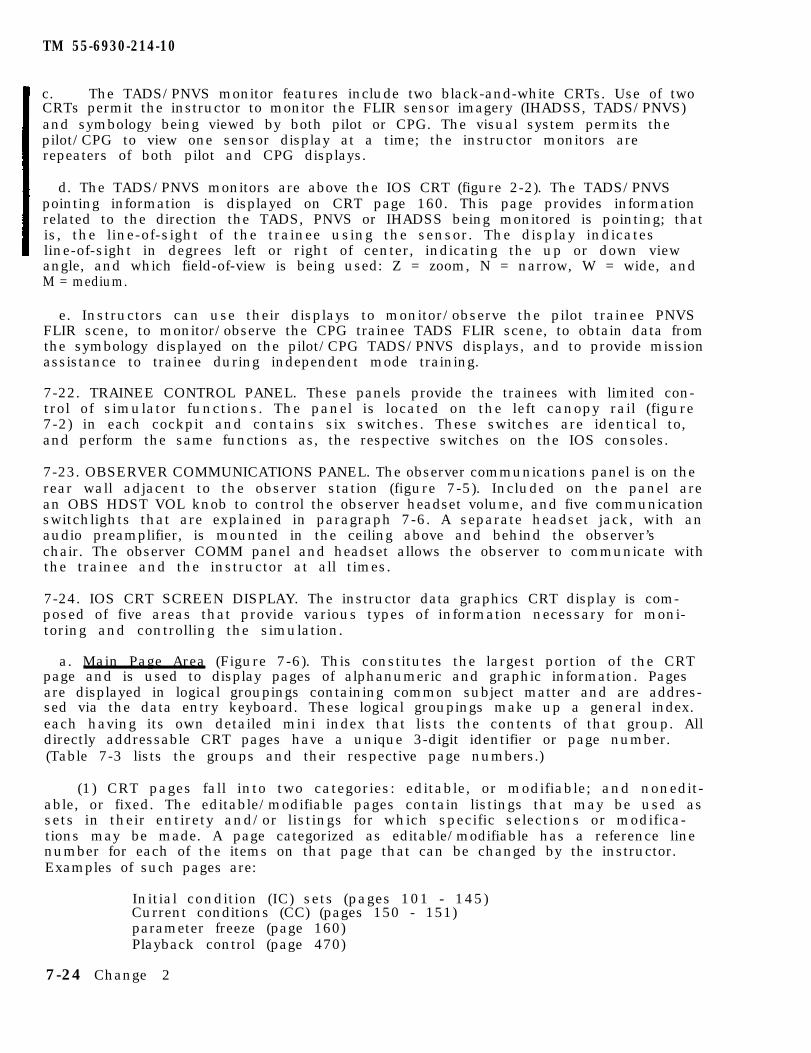
TM 55-6930-214-10
c. The TADS/PNVS monitor features include two black-and-white CRTs. Use of twoCRTs permit the instructor to monitor the FLIR sensor imagery (IHADSS, TADS/PNVS)and symbology being viewed by both pilot or CPG. The visual system permits thepilot/CPG to view one sensor display at a time; the instructor monitors arerepeaters of both pilot and CPG displays.
d. The TADS/PNVS monitors are above the IOS CRT (figure 2-2). The TADS/PNVSpointing information is displayed on CRT page 160. This page provides informationrelated to the direction the TADS, PNVS or IHADSS being monitored is pointing; thatis, the line-of-sight of the trainee using the sensor. The display indicatesline-of-sight in degrees left or right of center, indicating the up or down viewangle, and which field-of-view is being used: Z = zoom, N = narrow, W = wide, andM = medium.
e. Instructors can use their displays to monitor/observe the pilot trainee PNVSFLIR scene, to monitor/observe the CPG trainee TADS FLIR scene, to obtain data fromthe symbology displayed on the pilot/CPG TADS/PNVS displays, and to provide missionassistance to trainee during independent mode training.
7-22. TRAINEE CONTROL PANEL. These panels provide the trainees with limited con-trol of simulator functions. The panel is located on the left canopy rail (figure7-2) in each cockpit and contains six switches. These switches are identical to,and perform the same functions as, the respective switches on the IOS consoles.
7-23. OBSERVER COMMUNICATIONS PANEL. The observer communications panel is on therear wall adjacent to the observer station (figure 7-5). Included on the panel arean OBS HDST VOL knob to control the observer headset volume, and five communicationswitchlights that are explained in paragraph 7-6. A separate headset jack, with anaudio preamplifier, is mounted in the ceiling above and behind the observer’schair. The observer COMM panel and headset allows the observer to communicate withthe trainee and the instructor at all times.
7-24. IOS CRT SCREEN DISPLAY. The instructor data graphics CRT display is com-posed of five areas that provide various types of information necessary for moni-toring and controlling the simulation.
a. Main Page Area (Figure 7-6). This constitutes the largest portion of the CRTpage and is used to display pages of alphanumeric and graphic information. Pagesare displayed in logical groupings containing common subject matter and are addres-sed via the data entry keyboard. These logical groupings make up a general index.each having its own detailed mini index that lists the contents of that group. Alldirectly addressable CRT pages have a unique 3-digit identifier or page number.(Table 7-3 lists the groups and their respective page numbers.)
(1) CRT pages fall into two categories: editable, or modifiable; and nonedit-able, or fixed. The editable/modifiable pages contain listings that may be used assets in their entirety and/or listings for which specific selections or modifica-tions may be made. A page categorized as editable/modifiable has a reference linenumber for each of the items on that page that can be changed by the instructor.Examples of such pages are:
Initial condition (IC) sets (pages 101 - 145)Current conditions (CC) (pages 150 - 151)parameter freeze (page 160)Playback control (page 470)
7-24 Change 2
TM 55-6930-214-10
Figure 7-5. Observer Communications Panel
Change 2 7-25
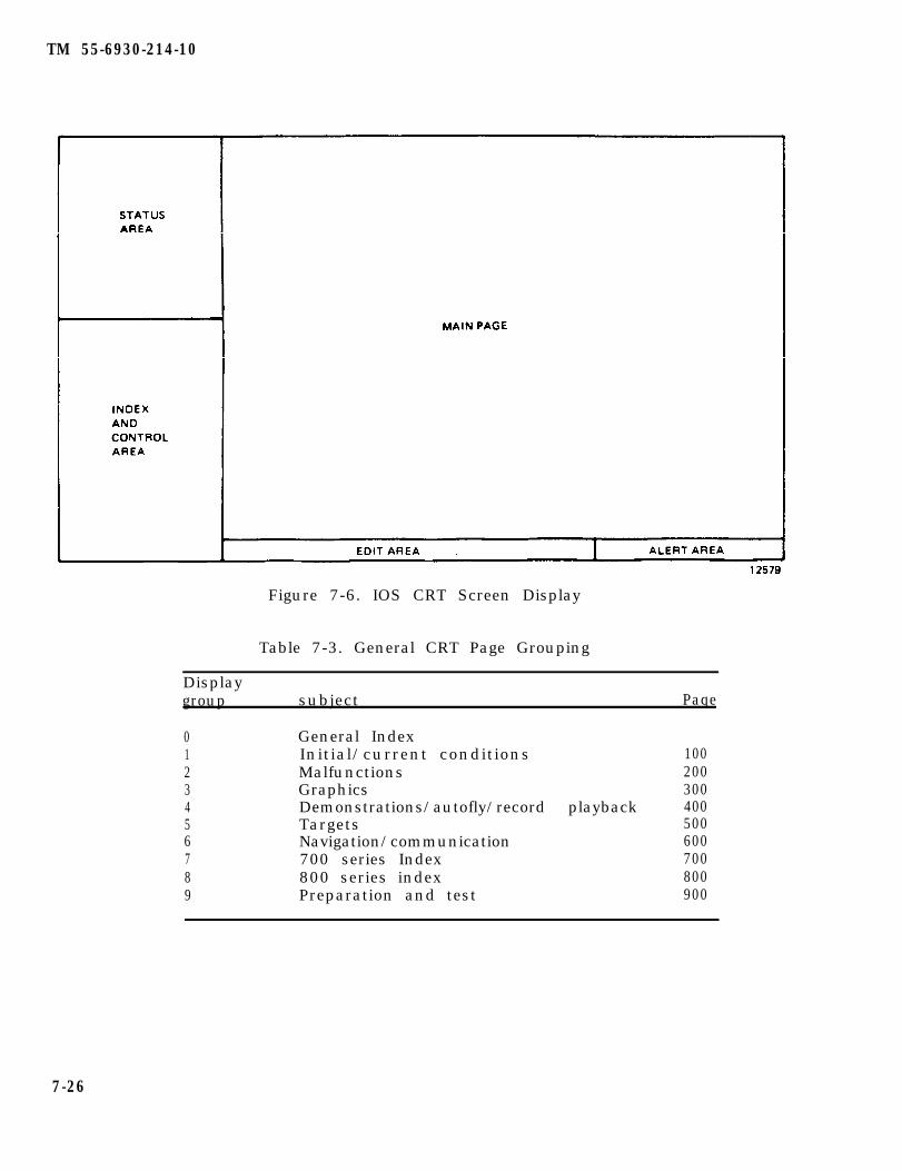
TM 55-6930-214-10
Figure 7-6. IOS CRT Screen Display
Table 7-3. General CRT Page Grouping
Displaygroup subject Paqe
0 General Index1 Initial/current conditions2 Malfunctions3 Graphics4 Demonstrations/autofly/record playback5 Targets6 Navigation/communication7 700 series Index8 800 series index9 Preparation and test
100200300400500600700800900
7-26
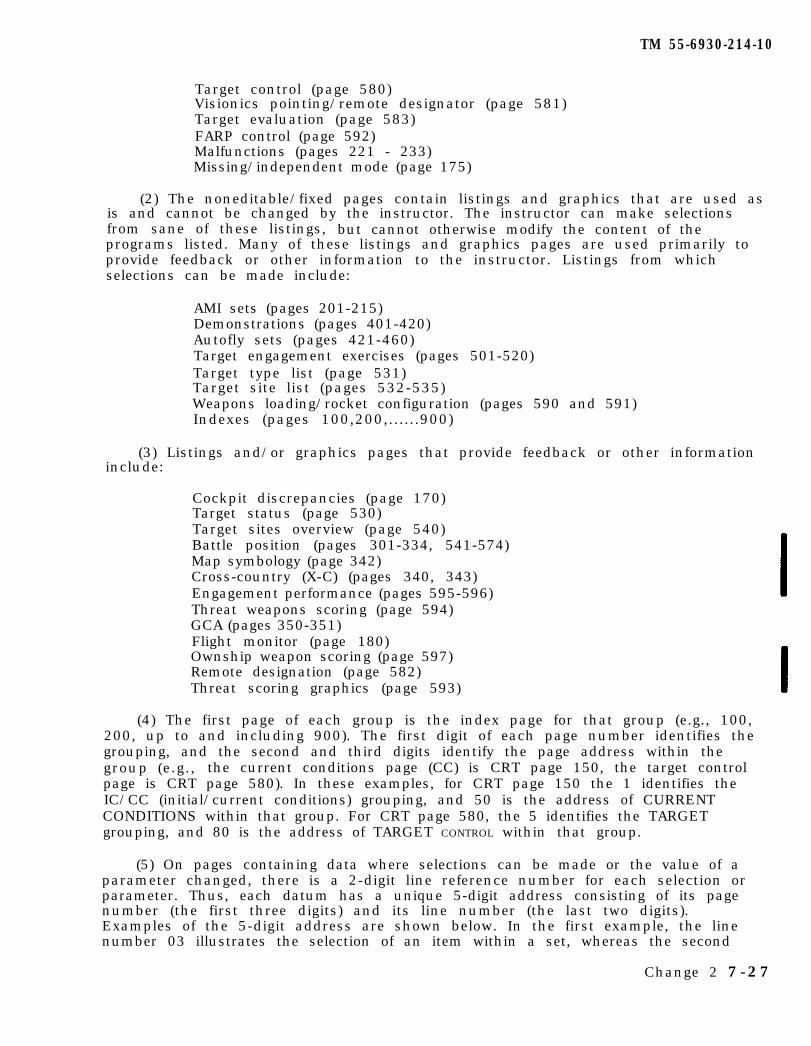
TM 55-6930-214-10
Target control (page 580)Visionics pointing/remote designator (page 581)Target evaluation (page 583)FARP control (page 592)Malfunctions (pages 221 - 233)Missing/independent mode (page 175)
(2) The noneditable/fixed pages contain listings and graphics that are used asis and cannot be changed by the instructor. The instructor can make selectionsfrom sane of these listings, but cannot otherwise modify the content of theprograms listed. Many of these listings and graphics pages are used primarily toprovide feedback or other information to the instructor. Listings from whichselections can be made include:
AMI sets (pages 201-215)Demonstrations (pages 401-420)Autofly sets (pages 421-460)Target engagement exercises (pages 501-520)Target type list (page 531)Target site list (pages 532-535)Weapons loading/rocket configuration (pages 590 and 591)Indexes (pages 100,200,......900)
(3) Listings and/or graphics pages that provide feedback or other informationinclude:
Cockpit discrepancies (page 170)Target status (page 530)Target sites overview (page 540)Battle position (pages 301-334, 541-574)Map symbology (page 342)Cross-country (X-C) (pages 340, 343)Engagement performance (pages 595-596)Threat weapons scoring (page 594)GCA (pages 350-351)Flight monitor (page 180)Ownship weapon scoring (page 597)Remote designation (page 582)Threat scoring graphics (page 593)
(4) The first page of each group is the index page for that group (e.g., 100,200, up to and including 900). The first digit of each page number identifies thegrouping, and the second and third digits identify the page address within thegroup (e.g., the current conditions page (CC) is CRT page 150, the target controlpage is CRT page 580). In these examples, for CRT page 150 the 1 identifies theIC/CC (initial/current conditions) grouping, and 50 is the address of CURRENTCONDITIONS within that group. For CRT page 580, the 5 identifies the TARGETgrouping, and 80 is the address of TARGET CONTROL within that group.
(5) On pages containing data where selections can be made or the value of aparameter changed, there is a 2-digit line reference number for each selection orparameter. Thus, each datum has a unique 5-digit address consisting of its pagenumber (the first three digits) and its line number (the last two digits).Examples of the 5-digit address are shown below. In the first example, the linenumber 03 illustrates the selection of an item within a set, whereas the second
Change 2 7-27
TM 55-6930-214-10
example illustrates the line number of a parameter (airspeed) that may be changedif the instructor so desires.
Example 1: Number 22303
2 MALFUNCTION group23 ENGINE SYSTEMS MALFUNCTIONS (Malfunction type #23)03 #1 HOT START (Line #03 within engine malfunctions)
Example 2: Number 10103
1 IC/CC group01 IC SET NUMBER 1 (Initial conditions set #01)03 AIRSPEED line reference number (Line #03 within IC set #1)
b. Status Area. The upper left-hand corner of the CRT display contains a statusarea. The status area displays a variety of information including mission elapsedtime, mode of CMS operation, aircraft flight data, rotor and engine data, activemalfunctions, weapons status, and communications channels in use. The informationis updated continuously and allows the instructor to monitor key elements of thetraining situation at a glance without changing CRT pages. (Figure 7-7 shows anexample of the status area as shown on the CRT, and table 7-4 Identifies each dataitem shown) As can be seen in figure 7-7, there are five subdivisions to thestatus area. The top area includes mission elapsed time (MET), CMS mode, visualmode, and features in use. The second area depicts aircraft flight, rotor, andengine data: the third area, active manual malfunctions; the fourth area, weaponsstatus: and the fifth area includes communications frequencies, trainee (student)identification, and threat event numbers. A second status area display includesthe Alpha Numeric Display and the number of chaff remaining.
c. Index and Control Area. The lower left-hand corner of the CRT display is anindex and control area. Each major grouping of CRT pages has a mini-index (figure7-8) that is usually displayed in the index and control area whenever any page fromthe parent group is displayed in the main page area. The mini-index provides aready reference to other items within the group during normal training operations.On some occasions, the mini-index is replaced with a special reference list uniqueto the display in the main page area of the CRT. For example, whenever a GCA pageis displayed, the index and control area contains reference numbers for keyboardinputs that initiate and terminate the GCA program at the airfield. In addition.certain graphic CRT pages have reference lists for erasing or recalling groundtrack traces and for advancing the field-of-fire on the battle position pages.
d. Edit Area. The last three rows of the CRT display are an edit area (figure7-6). This area echos or repeats all of the instructor keystrokes, prior toentry. The edit area also displays operator error messages (e.g., keystroking anumber beyond the established range of values for a given entry). Erroneous key-strokes can be deleted one item at a time via the backspace key, or the entire editline can be deleted via the clear key.
e. Alert Area. The lower right-hand corner of the CRT display is for alert mes-sages (figure 7-6). This area displays systems messages to the instructor. Examplesof the type of messages that appear in the alert area are: IC IN PROGRESS - whenan IC has been entered and is being set up, this message appears in the alert area:22303 #1 HOT START - when an AMI set is in use and a malfunction is triggered, amessage similar to this appears for 10 seconds prior to insertion/activation.
7-28 Change 2
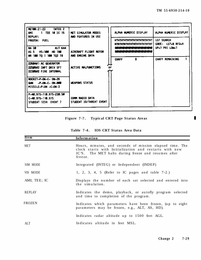
TM 55-6930-214-10
Figure 7-7. Typical CRT Page Status Areas
Table 7-4. IOS CRT Status Area Data
Item Information
MET Hours, minutes, and seconds of mission elapsed time. Theclock starts with Initialization and restarts with newIC’S. The MET halts during freeze and resumes afterfreeze.
SIM MODE
VIS MODE
AMI; TEE; IC
REPLAY
FROZEN
ALT
Integrated (INTEG) or Independent (INDEP)
1, 2, 3, 4, 5 (Refer to IC pages and table 7-2.)
Displays the number of each set selected and entered intothe simulation.
Indicates the demo, playback, or autofly program selectedand time to completion of the program.
Indicates which parameters have been frozen, (up to eightparameters may be frozen, e.g., ALT, AS, HD).
Indicates radar altitude up to 1500 feet AGL.
Indicates altitude in feet MSL.
Change 2 7-29
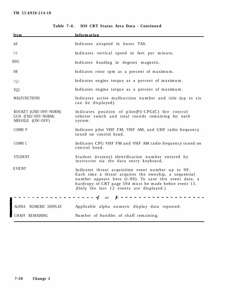
TM 55-6930-214-10
Item
Table 7-4. IOS CRT Status Area Data - Continued
Information
AS
VS
HDG
NR
TQ1
TQ2
MALFUNCTIONS
ROCKET (GND/OFF/NORM)GUN (FXD/OFF/NORM)MISSILE (ON/OFF)
COMM P
COMM C
STUDENT
Indicates airspeed in knots TAS.
Indicates vertical speed in feet per minute.
Indicates heading in degrees magnetic.
Indicates rotor rpm as a percent of maximum.
Indicates engine torque as a percent of maximum.
Indicates engine torque as a percent of maximum.
Indicates active malfunction number and title (up to sixcan be displayed).
Indicates position of pilot(P)/CPG(C) fire controlselector switch and total rounds remaining for eachsystem.
Indicates pilot VHF FM, VHF AM, and UHF radio frequencytuned on control head.
Indicates CPG VHF FM and VHF AM radio frequency tuned oncontrol head.
Student (trainee) identification number entered byinstructor via the data entry keyboard.
EVENT Indicates threat acquisition event number up to 99.Each time a threat acquires the ownship, a sequentialnumber appears here (1-99). To save this event data, ahardcopy of CRT page 594 must be made before event 13.(Only the last 12 events are displayed.)
or
ALPHA NUMERIC DISPLAY Applicable alpha numeric display data repeated.
CHAFF REMAINING Number of bundles of chaff remaining.
7-30 Change 2
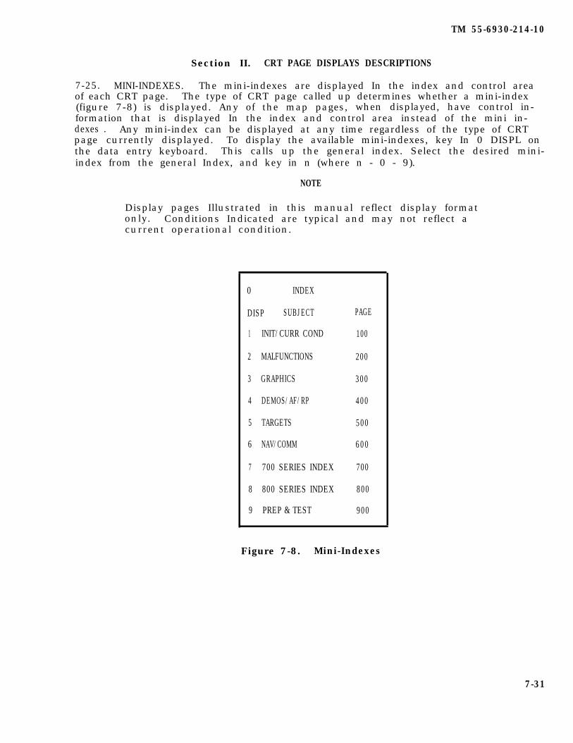
TM 55-6930-214-10
Section II. CRT PAGE DISPLAYS DESCRIPTIONS
7-25. MINI-INDEXES. The mini-indexes are displayed In the index and control areaof each CRT page. The type of CRT page called up determines whether a mini-index(figure 7-8) is displayed. Any of the map pages, when displayed, have control in-formation that is displayed In the index and control area instead of the mini in-dexes . Any mini-index can be displayed at any time regardless of the type of CRTpage currently displayed. To display the available mini-indexes, key In 0 DISPL onthe data entry keyboard. This calls up the general index. Select the desired mini-index from the general Index, and key in n (where n - 0 - 9).
NOTE
Display pages Illustrated in this manual reflect display formatonly. Conditions Indicated are typical and may not reflect acurrent operational condition.
0 INDEX
DISP SUBJECT PAGE
1 INIT/CURR COND 100
2 MALFUNCTIONS 200
3 GRAPHICS 300
4 DEMOS/AF/RP 400
5 TARGETS 500
6 NAV/COMM 600
7 700 SERIES INDEX 700
8 800 SERIES INDEX 800
9 PREP & TEST 900
Figure 7-8. Mini-Indexes
7-31

TM 55-6930-214-10
7-26. INITIAL CONDITIONS. Initial condition (IC sets (figures 7-9 and 7-10) arepreprogramed sets of operation configurations and geographical locations for thesimulated aircraft. The computer memory is capable of storing up to 45 permanentIC sets. The setup points associated with automated training programs (demonstra-tions) can also be used as IC sets. In addition, the store/reset and record/play-back features offer additional sources of initial conditions. Each IC set placesthe simulated aircraft in a specific geographical location and configuration (e.g.,aircraft dead on the ramp, aircraft with engines running at an airport, aircraftairborne at 200 feet, etc.). (A sample set of initial conditions is shown infigure 7-10.) The IC sets provide a fairly broad range of starting points forvarious instructional activities and save instructor setup time.
a. If none of the permanent IC sets meets requirements. individual parameterscan be temporarily changed by the instructor. Each set of initial conditions con-tains items/parameters and three command lines. For any sat of conditions (e.g..the permanent IC’s. IC’s from auto training programs), the instructor CM retainspecific parameters and can modify the value of the remaining items; change X-Ylocation, add/delete fuel (at zero pounds of fuel, the engine flames out: amount offuel onboard affects the center of gravity). change OAT, change wind direction (WD)and wind velocity (WV), etc. In addition, the instructor can build a set oftemporary conditions to wet a specific training requirement. In this way, theinstructor can design a temporary set of conditions to establish and control allparameters of the training period.
b. Initial conditions sets are accessed through the keyboard at the IOS in-dex of permanent IC sets appears on CRT page 100. The specific characteristics ofa given set can be displayed for review (or modification) by keying in its linenumber and depressing DISPL on data entry keyboard. (Refer to table 7-5 for therange of values for each parameter/item.) If review or modification is not neces-sary, an IC set can be entered directly into the simulation by keying in its 3-digit identifier code and depressing ENTER. IC sets can be displayed for review atany time, but the CMS rust be in FREEZE to enter an IC.
c. The initial conditions set is used to place the CMS in the desired geogra-phical location and configuration to start training, to move the CMS to a newlocation and/or configuration during training, end to establish or modify a givenIC set to suit particular training needs (e.g., change altitude, airspeed, heading.fuel weight, turbulence, etc.).
NOTE
multiple-page IC’s (101A. 101B, etc.) can be brought up bydepressing the PAGE FWD switchlight on the data entry keyboard.
7-32 Change 2
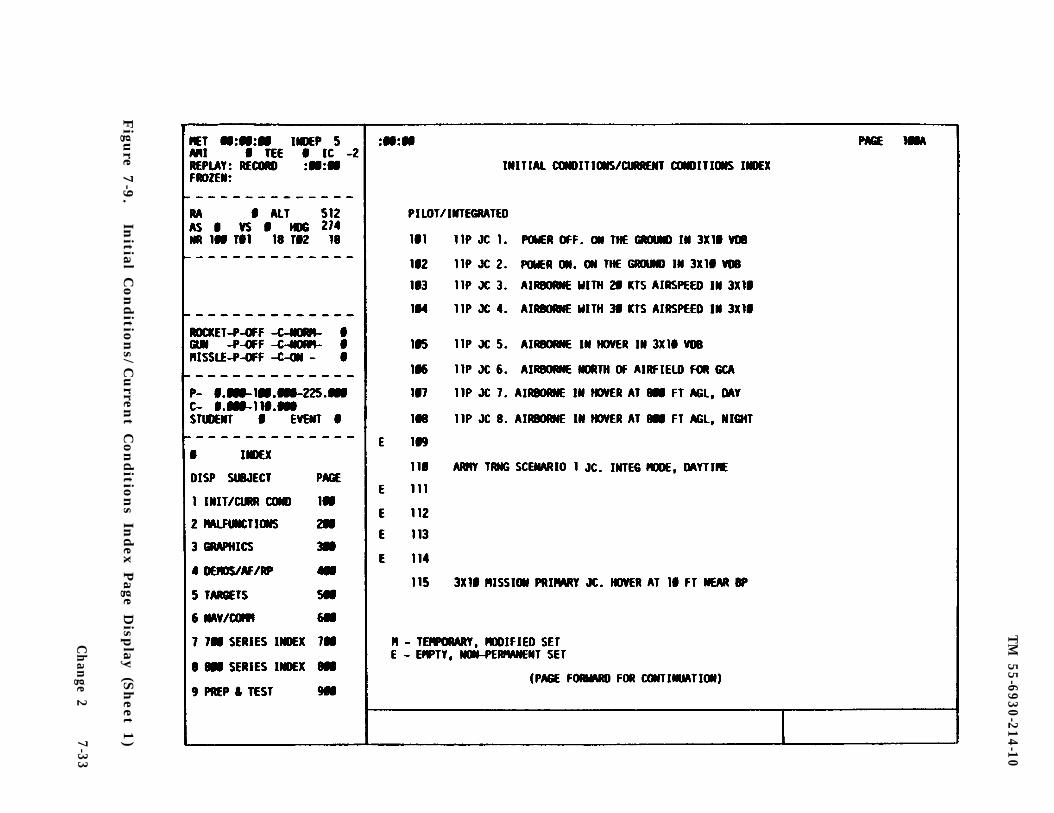
TM
55-6930-214-10
Figu
re 7-9
.In
itial Con
ditio
ns/
Curren
t Con
ditio
ns In
dex
Page D
isplay
(Sh
eet 1)
Ch
ange 2
7-33
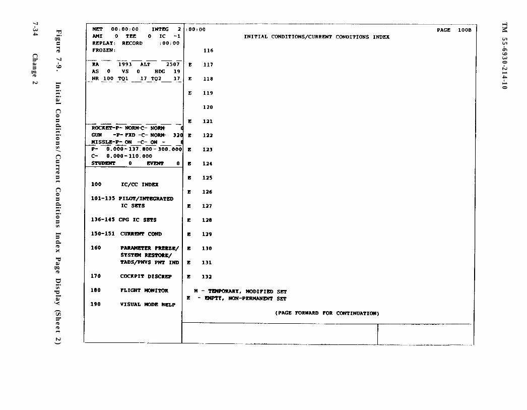
TM
55-6930-214-10
Figu
re 7-9
.In
itial Con
ditio
ns/
Curren
t Con
ditio
ns In
dex
Page D
isplay
(Sh
eet 2)
7-34C
han
ge 2
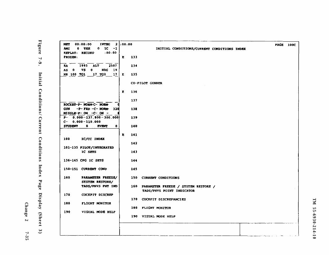
TM
55-6930-214-10
Figu
re 7-9
.In
itial Con
ditio
ns/
Curren
t Con
ditio
ns In
dex
Page D
isplay
(Sh
eet 3)
Ch
ange 2
7-35

TM
55-6930-214-10
Figu
re 7-1
0.
Initial
Conditio
ns
Page
Disp
lay (S
heet
1)
7-3
6C
han
ge 2
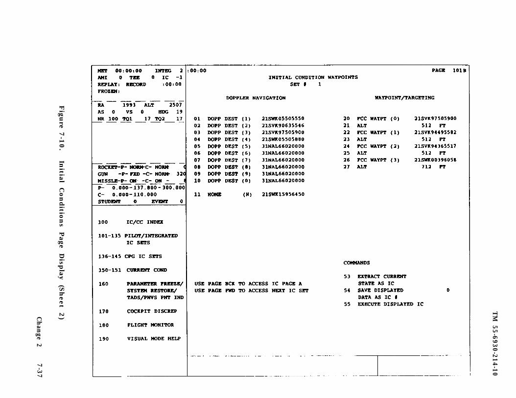
TM
55-6930-214-10
Figu
re 7-1
0.
Initial
Conditio
ns
Page
Disp
lay (S
heet
2)Ch
ange 2
7-3
7
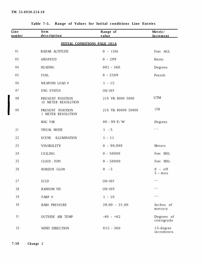
TM 55-6930-214-10
Table 7-5. Range of Values for Initial conditions Line Entries
Line Item Range of Metric/number description value Increment
01
03
04
05
06
07
08
09
UTM
UTM
21
22
23
24
25
26
27
28
29
30
31
32
7-38
INITIAL CONDITIONS PAGE 101A
RADAR ALTITUDE 0 - 1500
AIRSPEED 0 - 299
HEADING 001 - 360
FURL 0 - 2509
WEAPONS LOAD # 1 - 15
ENG STATUS ON/OFF
PRESENT POSITION 21S VK 8000 500010 METER RESOLUTION
PRESENT POSITION 21S VK 80000 500001 METER RESOLUTION
MAG VAR 00 - 99 E/W
VISUAL MODE 1 - 5
SCENE ILLUMINATION 1 - 11
VISIBILITY 0 - 99,999
CEILING 0 - 50000
CLOUD - TOPS 0 - 50000
HORIZON GLOW 0 - 5
SCUD ON/OFF
RANDOM VIS ON/OFF
FARP # 1 - 10
BAR0 PRESSURE 28.00 - 31.00
OUTSIDE AIR TEMP -40 - +62
WIND DIRECTION 015 - 360
Change 2
Feet AGL
Knots
Degrees
Pounds
Degrees
- -
Meters
Feet MSL
Feet MSL
0 - off5 - max
- -
- -
- -
Inches ofmercury
Degrees ofcentigrade
15-degreeincrements
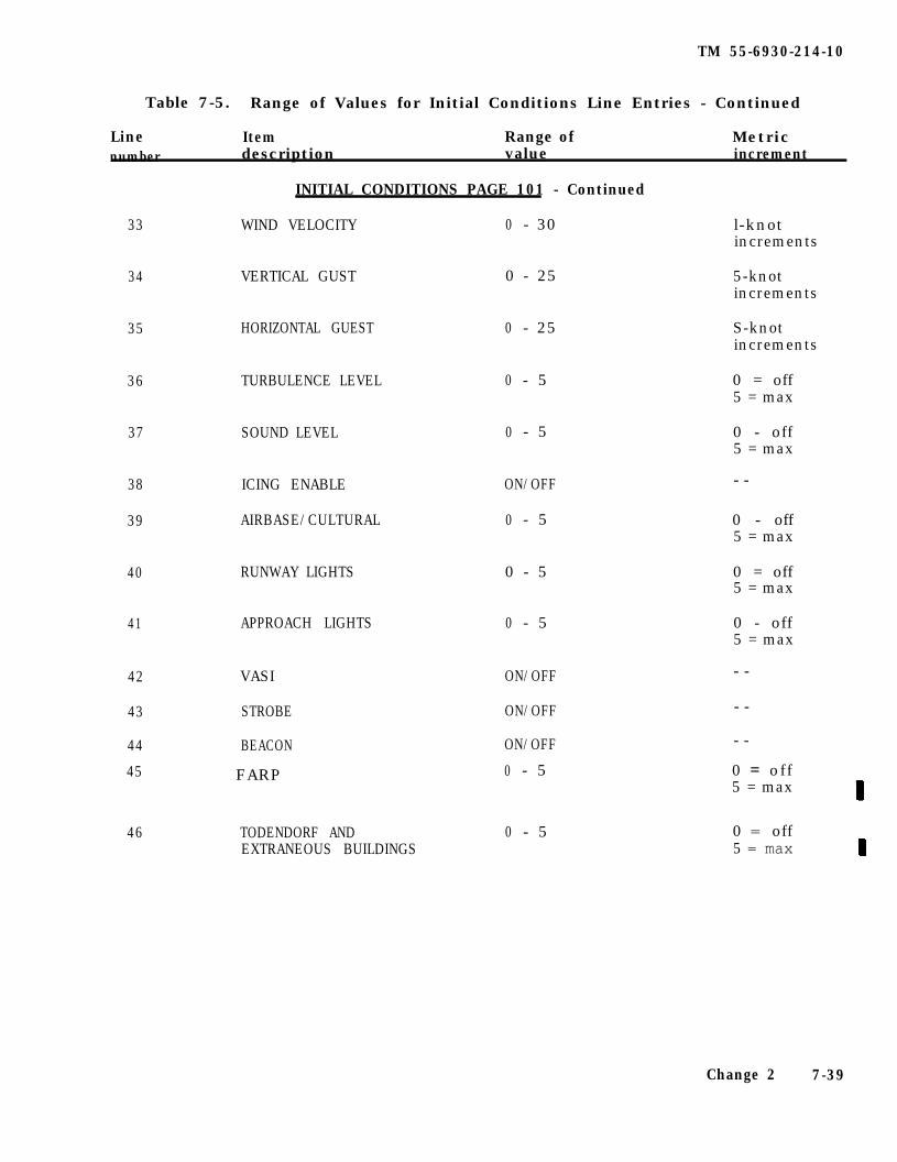
TM 55-6930-214-10
Table 7-5. Range of Values for Initial Conditions Line Entries - Continued
MetricLine Item Range ofnumber description value increment
INITIAL CONDITIONS PAGE 101 - Continued
33 WIND VELOCITY 0 - 30 l-knotincrements
34 VERTICAL GUST 0 - 25 5-knotincrements
35 HORIZONTAL GUEST 0 - 25 S-knotincrements
36 TURBULENCE LEVEL 0 - 5 0 = off5 = max
37 SOUND LEVEL 0 - 5 0 - off5 = max
38 ICING ENABLE ON/OFF - -
39 AIRBASE/CULTURAL 0 - 5 0 - off5 = max
40 RUNWAY LIGHTS 0 - 5 0 = off5 = max
41 APPROACH LIGHTS 0 - 5 0 - off5 = max
42 VASI ON/OFF - -
43 STROBE ON/OFF - -
44 BEACON ON/OFF - -
45 0 - 5 0 = off5 = max
FARP
46 TODENDORF AND 0 - 5 0 = offEXTRANEOUS BUILDINGS 5 = max
Change 2 7-39
TM 55-6930-214-10
Table 7-5. Range of Values for Initial Conditions Line Entries - Continued
Line Itemnumber description
Range ofvalue
Metric/increment
53
54
55
01 - 10
11
20,22,24,26
21,23,25,27
53,54,55
INITIAL CONDITIONS PAGE 10lA - Continued
EXTRACT CURRENT - -STATE AS IC
- -
SAVE DISPLAYED 1 - 45DATA AS IC #
EXECUTE DISPLAYED IC - -
INITIAL CONDITIONS WAYPOINTS PAGE 10lB
DOPP DEST 21S WK 2000 5000
HOME 21S VK 8000 8200
FCC WAYPT 21S WK 2000 8200
ALT 0 - 9999
Same as page 10lA
- -
UTM
UTM
UTM
Feet
d. All FCC waypoints (lines 20, 22, 24, and 26) are programmable when operatingthe CMS In the independent mode. (Refer to paragraph 7-57 for independent mode/missing man operation.)
e. There are three command lines in the lower right-hand corner of each IC page(lines 53, 54, and 55). Lines 53 and 54 provide the capability to save the modi-fied IC set for reuse during the training period or to save any position and stateto which the simulator is flown during a period. Line 55 is the command line usedto Insert a displayed IC into the simulated environment.
(1) Whatever current conditions exist or have been modified can be extractedas an IC by keying in 53 ENTER while in freeze.
(2) The conditions extracted In step 1 can now be stored in the numerical lo-cation designated and can be recalled during the remainder of the period by keyingin 54 TAB _ _ (any number 1 through 45) and depressing ENTER. This temporary ICset replaces the set normally stored at that location.
(3) In changing from one IC set to another, it is possible to encounter asituation in which current switch and/or control positions art incompatible withthose of the new IC. When this occurs, an alert message appears in the CRT alertarea directing the instructor to call up cockpit discrepancy page 170 (figure7-11): where specific discrepancies are Identified. These must be corrected beforethe new IC can be accepted by the computer system. If the instructor determinesthe discrepancy is not critical, depressing FREEZE causes it to override thediscrepancy: however, a crash situation may result.
7-40 Change 1
TM
55-6930-214-10
Figu
re 7-1
1.
Cock
pit
Discrep
ancies
Page
Disp
lay
Ch
ange 2
7-41
TM 55-6930-214-10
7-27. CURRENT CONDITIONS. Current conditions pages 150 and 151 are lists of thecurrent parameters and conditions of the simulated aircraft at any given time whileit is being used for training. Parameters being shown are identical to the initialconditions (IC) set while the stimulator is in freeze following initialization.When out of freeze, the current conditions pages reflect the actual state of thesimulator.
The status of each of the items/parameters is shown on the currant condi-tions CRT pages (figure 7-12). Items or parameters with line reference numbers canbe modified during training. Host items/parameters can be changed while out offreeze. but to change others, the simulator must be in a freeze state to precludediscontinuities. The current conditions pages contain the following categories:
Aircraft TacticsVisual MiscellaneousEnvironmental Doppler navigationLighting Waypoint/targeting
b. The first four categories cm page 150 are essentially the same on the currentconditions page as in the IC sets.
The current conditions page located in group 1 (IC/CC) can be accessed viathe data entry keyboard by keying in 150 DISPL. (Ranges of values for eachparameter/item are listed In table 7-6.) To modify the following items/parameters,the simulator must be In a freeze state:
AltitudeHeadingWeapons loadPresent positionPresent position
Line 01/02Line 04Line 06Line 08 10 meter resolutionLine 09 1 meter resolution
NOTE
Random visibility (line 28) is available only if the visibility(line 23) is 2000 feet or below.
NOTE
To change items/parameters when operating in the independentmode, refer to missing man operating paragraph 7-57 and missingman/independent mode display CRT page 175.
d. Two categories of Information/control included on the current conditionspage, but not on the initial conditions page, art tactics and miscellaneous.(Refer to tables 7-7 and 7-8.)
e. Any set of current conditions can be saved temporarily by depressing STORE onthe IOS forward control panel. This data is then available for recall andrelocation by depressing PROB FREEZE and RESET. If the instructor desires to savemore than one set of current conditions during a period. they can be saved bydesignating the sets as a temporary IC set. Up to 45 IC sets can be temporarilysaved. To save a temporary IC set from current conditions, perform the followingprocedures:
7-42 Change 2
TM
55-6930-214-10
Figu
re 7-1
2.
Curren
t Con
ditio
ns P
age Disp
lay (S
heet 1
)Chan
ge 27-43
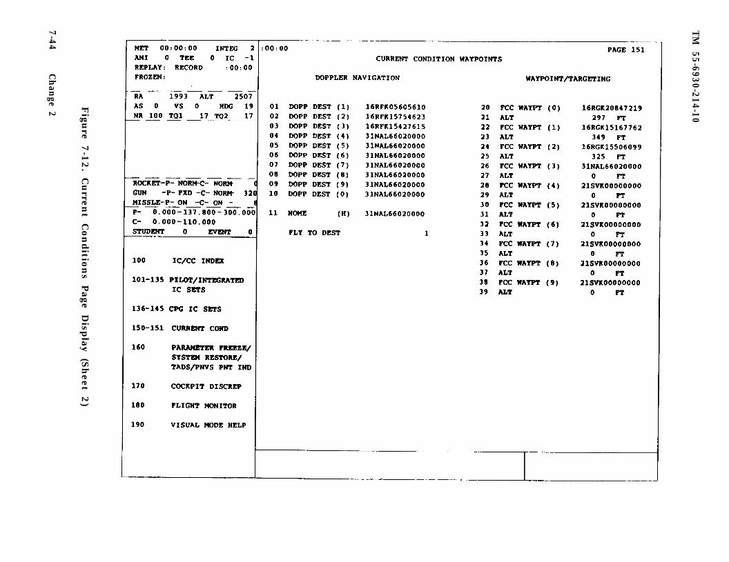
TM
55-6930-214-10
Figu
re 7-1
2. C
urren
t Con
ditio
ns P
age Disp
lay (S
heet 2
)
7-44C
han
ge 2
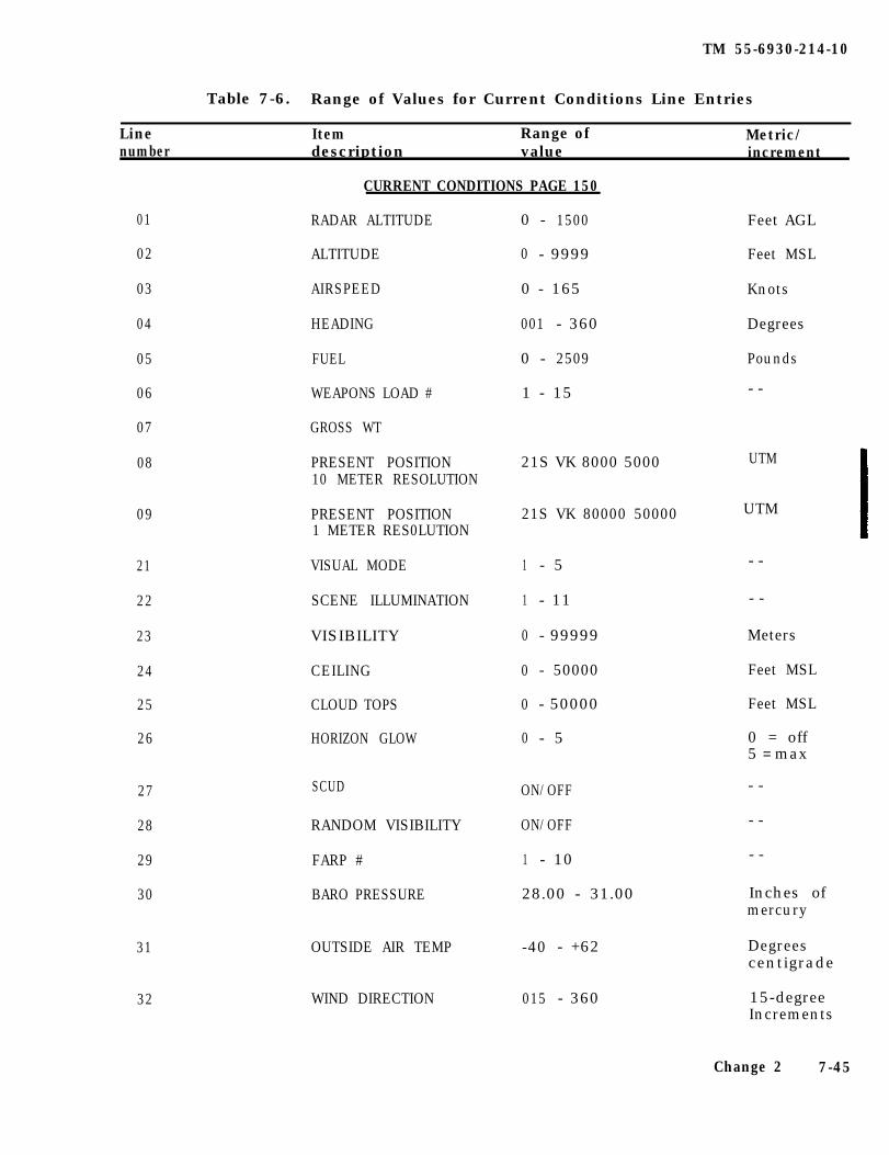
TM 55-6930-214-10
Table 7-6. Range of Values for Current Conditions Line Entries
Line Item Range of Metric/number description value increment
CURRENT CONDITIONS PAGE 150
01
02
03
04
05
06
07
08 UTM
09 UTM
21
22
23
24
25
26
27
28
29
30
SCUD
31
32 WIND DIRECTION
RADAR ALTITUDE
ALTITUDE
AIRSPEED
HEADING
FUEL
WEAPONS LOAD #
GROSS WT
PRESENT POSITION10 METER RESOLUTION
PRESENT POSITION1 METER RES0LUTION
VISUAL MODE
SCENE ILLUMINATION
VISIBILITY
CEILING
CLOUD TOPS
HORIZON GLOW
RANDOM VISIBILITY
FARP #
BARO PRESSURE
OUTSIDE AIR TEMP -40 - +62
0 - 1500
0 - 9999
0 - 165
001 - 360
0 - 2509
1 - 15
21S VK 8000 5000
21S VK 80000 50000
1 - 5
1 - 11
0 - 99999
0 - 50000
0 - 50000
0 - 5
ON/OFF
ON/OFF
1 - 10
28.00 - 31.00
015 - 360
Feet AGL
Feet MSL
Knots
Degrees
Pounds
- -
- -
- -
Meters
Feet MSL
Feet MSL
0 = off5 = max
- -
- -
- -
Inches ofmercury
Degreescentigrade
15-degreeIncrements
Change 2 7-45
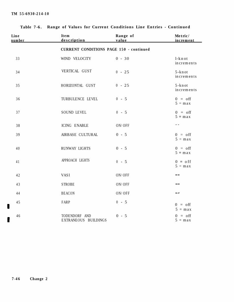
TM 55-6930-214-10
Table 7-6. Range of Values for Current Conditions Line Entries - Continued
Line Item Range of Metric/number description value increment
CURRENT CONDITIONS PAGE 150 - continued
33 WIND VELOCITY 0 - 30 l-knotincrements
34 VERTICAL GUST 0 - 25 5-knotincrements
35 HORIZONTAL GUST 0 - 25 5-knotincrements
36 TURBULENCE LEVEL 0 - 5 0 = off5 = max
37 SOUND LEVEL 0 - 5 0 = off5 = max
38
39
ICING ENABLE
AIRBASE CULTURAL
ON/OFF
0 - 5
- -
0 = off5 = max
40 RUNWAY LIGHTS 0 - 5 0 = off5 = max
APPROACH LIGHTS 0 = of f5 = max
41 0 - 5
42
43
44
VASI ON/OFF
STROBE ON/OFF
BEACON ON/OFF
FARP 0 - 545 0 = off5 = max
46 TODENDORF ANDEXTRANEOUS BUILDINGS
0 - 5 0 = off5 = max
7-46 Change 2
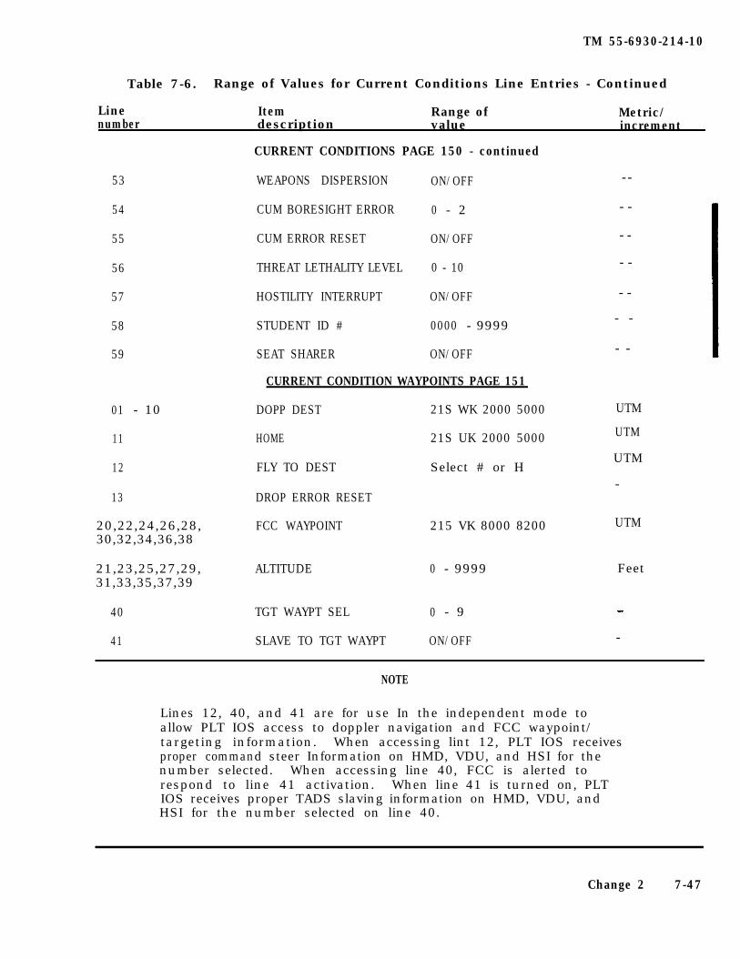
TM 55-6930-214-10
Table 7-6. Range of Values for Current Conditions Line Entries - Continued
Line Item Range of Metric/number description value increment
53
54
55
56
57
58
59
--
- -
- -
- -
01 - 10
11
12
13
20,22,24,26,28,30,32,34,36,38
21,23,25,27,29,31,33,35,37,39
40
41
CURRENT CONDITIONS PAGE 150 - continued
WEAPONS DISPERSION ON/OFF
CUM BORESIGHT ERROR 0 - 2
CUM ERROR RESET ON/OFF
THREAT LETHALITY LEVEL 0 - 10
HOSTILITY INTERRUPT ON/OFF
STUDENT ID # 0000 - 9999
SEAT SHARER ON/OFF
CURRENT CONDITION WAYPOINTS PAGE 151
DOPP DEST 21S WK 2000 5000
HOME 21S UK 2000 5000
FLY TO DEST Select # or H
DROP ERROR RESET
FCC WAYPOINT 215 VK 8000 8200
UTM
UTM
UTM
-
UTM
ALTITUDE 0 - 9999 Feet
TGT WAYPT SEL 0 - 9
SLAVE TO TGT WAYPT ON/OFF
- -
- -
- -
-
NOTE
Lines 12, 40, and 41 are for use In the independent mode toallow PLT IOS access to doppler navigation and FCC waypoint/targeting information. When accessing lint 12, PLT IOS receivesproper command steer Information on HMD, VDU, and HSI for thenumber selected. When accessing line 40, FCC is alerted torespond to line 41 activation. When line 41 is turned on, PLTIOS receives proper TADS slaving information on HMD, VDU, andHSI for the number selected on line 40.
Change 2 7-47
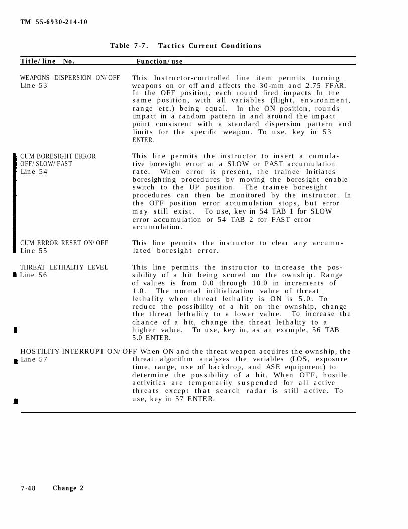
TM 55-6930-214-10
Title/line No.
Table 7-7. Tactics Current Conditions
Function/use
WEAPONS DISPERSION ON/OFF This Instructor-controlled line item permits turningLine 53 weapons on or off and affects the 30-mm and 2.75 FFAR.
In the OFF position, each round fired impacts In thesame position, with all variables (flight, environment,range etc.) being equal. In the ON position, roundsimpact in a random pattern in and around the impactpoint consistent with a standard dispersion pattern andlimits for the specific weapon. To use, key in 53ENTER.
CUM BORESIGHT ERROROFF/SLOW/FASTLine 54
This line permits the instructor to insert a cumula-tive boresight error at a SLOW or PAST accumulationrate. When error is present, the trainee Initiatesboresighting procedures by moving the boresight enableswitch to the UP position. The trainee boresightprocedures can then be monitored by the instructor. Inthe OFF position error accumulation stops, but errormay still exist. To use, key in 54 TAB 1 for SLOWerror accumulation or 54 TAB 2 for FAST erroraccumulation.
CUM ERROR RESET ON/OFF This line permits the instructor to clear any accumu-Line 55 lated boresight error.
THREAT LETHALITY LEVEL Line 56
This line permits the instructor to increase the pos-sibility of a hit being scored on the ownship. Rangeof values is from 0.0 through 10.0 in increments of1.0. The normal iniltialization value of threatlethality when threat lethality is ON is 5.0. Toreduce the possibility of a hit on the ownship, changethe threat lethality to a lower value. To increase thechance of a hit, change the threat lethality to ahigher value. To use, key in, as an example, 56 TAB5.0 ENTER.
HOSTILITY INTERRUPT ON/OFF When ON and the threat weapon acquires the ownship, the Line 57 threat algorithm analyzes the variables (LOS, exposure
time, range, use of backdrop, and ASE equipment) todetermine the possibility of a hit. When OFF, hostileactivities are temporarily suspended for all activethreats except that search radar is still active. Touse, key in 57 ENTER.
7-48 Change 2
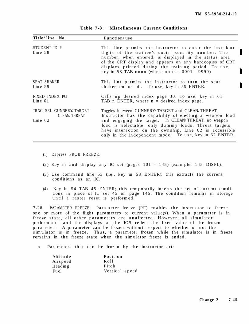
TM 55-6930-214-10
Table 7-8. Miscellaneous Current Conditions
Title/line No. Function/use
STUDENT ID #Line 58
This line permits the instructor to enter the last fourdigits of the trainee’s social security number. Thenumber, when entered, is displayed in the status areaof the CRT display and appears on any hardcopies of CRTdisplays printed during the training period. To use,key in 58 TAB nnnn (where nnnn - 0001 - 9999)
SEAT SHAKERLine 59
This lint permits the instructor to turn the seatshaker on or off. To use, key in 59 ENTER.
FIXED INDEX PGLine 61
Calls up desired index page 30. To use, key in 61TAB n ENTER, where n = desired index page.
TRNG SEL GUNNERY/TARGET Toggles between GUNNERY/TARGET and CLEAN/THREAT.CLEAN/THREAT Instructor has the capability of electing a weapon load
Line 62 and engaging the target. In CLEAN/THREAT, no weaponload is selectable: only dummy loads. Threat targetshave interaction on the ownship. Line 62 is accessibleonly in the independent mode. To use, key in 62 ENTER.
(1) Depress PROB FREEZE.
(2) Key in and display any IC set (pages 101 - 145) (example: 145 DISPL).
(3) Use command line 53 (i.e., key in 53 ENTER); this extracts the currentconditions as an IC.
(4) Key in 54 TAB 45 ENTER; this temporarily inserts the set of current condi-tions in place of IC set 45 on page 145. The condition remains in storageuntil a raster reset is performed.
7-28. PARAMETER FREEZE. Parameter freeze (PF) enables the instructor to freezeone or more of the flight parameters to current value(s). When a parameter is infreeze state, all other parameters are unaffected. However, all simulatorperformance and the displays at the IOS reflect the fixed value of the frozenparameter. A parameter can be frozen without respect to whether or not thesimulator is in freeze. Thus, a parameter frozen while the simulator is in freezeremains in the freeze state when the simulator freeze is ended.
a. Parameters that can be frozen by the instructor art:
AltitudeAirspeedHeadingFuel
PositionRollPitchVertical speed
Change 2 7-49
TM 55-6930-214-10
b. The parameter freeze feature is accessed through CRT page 160 (figure 7-13)on the IOS CRT. Parameters that can be frozen art listed by lint number. To freezea given parameter, key in its line number at the keyboard and depress ENTER. Tounfreeze a frozen parameter, repeat the process. The parameter freeze page in-cludes two command lines at the bottom, lines 88 and 99. To freeze all parameterssimultaneously, key in 88 ENTER. To clear all frozen parameters, key in 99 ENTER.If all parameters are frozen, individual parameters cannot be selected to be unfro-zen. Parameters that have been frozen art displayed in the status area of the CRT.
C. The parameter freeze feature is used to freeze one or more parameters. to re-duce trainee task load, to assist the Instructional staff in preparing demonstra-tions and autofly programs, and to freeze all parameters.
d. In the independent mode of operation, freezing a parameter in one cockpit hasno effect on the other cockpit. In integrated mode of operation, freezing a para-meter In one cockpit also freezes it in the other.
e. The systems restore controls permit the Instructor to restore a system to itsbasic state. The systems that can be restored are charge battery (line 21), chargehydraulic accumulator (line 22), align HARS (line 23). and cool FLIR (line 24).Use restore all systems (line 77) to Instantaneously restore the above items (lines21 through 24).
f . The TADS/PNVS point Indicator display will display point indicatorinformation. It will display TADS, PNVS, or IHADSS, based on user selection.Field of view will display N, M, W, or Z, for narrow, medium, wide, or zoomselections. In addition, the pilot or copilot azimuth and elevation angles aredisplayed. No pilot or copilot information is displayed when power is off or noselections were made.
7-29. PLIGHT MONITOR. The flight monitor page is a display-only page for monitor-ing 34 different flight parameters. This page allows the instructor to evaluatetrainees performance during the simulation process. The flight monitor page(figure 7-14) is accessed through the data entry keyboard by keying in 180 DISPL,and is included on the IC index page.
7-30. VISUAL MODE HELP PAGE. This Page is a display-only page (figure 7-15) usedin conjunction with the IC and CC pages to aid the instructor in determining thecorrect visual mode for the type of training to be accomplished, either integratedor independent. This page displays visual resources for both the pilot and CPG.The visual mode help page is in group 1 (IC/CC) and can be accessed via the dataentry keyboard by keying in 190 DISPL.
7-31. NAVIGATION/ COMMUNICATIONS. The nav/comm facilities pages 601 and 602 defineeach navigation and communication facility in the gaming area. Each facility isdefined by the following:
ID/nameTypeFrequency
LocationStatus
a. The nav/comm facilities pages (figures 7-16 through 7-18) are in group 6(NAV/COM) and can be accessed via the data entry keyboard by keying in 601 DISPL.CRT page 602 can be accessed by depressing PAGE FWD or by keying in 602 DISPL.
7-50 Change 2
TM 55-6930-214-10
b .e . g . ,
To activate/deactivate a facility, key in the facility number and ENTERkeystroke 05 ENTER). This process toggles the status indication on the CRT
page. This can also be performed on the tactical instrument gaming area pagedisplay (CRT page 341), in the index and control area.
Nav/comm facilities can also be viewed graphically on the tactical instrumentgaming area page display (CRT page 341).
7-31.1. UHF-AH Have Quick Radio. The UHF-AH Have Quick radio is page number 610(Figure 7-18.1). This page can be accessed directly by keying in 610 DISPL, or bypressing PAGE FWD from page 602.
a. The page contains seven lines which are editable by the instructor. Theseare :
Day of the month (Specifies WOD)Frequency selectionAnti jam mode selectionSatellite activeTime of day manual entryTime of day mismatchUHF jamming signal
b. In addition, the following are displayed at the IOS, but are not editable:
Jammed frequencyRequired word of day frequency for channels 15 to 20Pilot entered word of day frequency for channels 15 to 20UHF frequency selectionPilot and CPG VHF frequency selection
Change 2 7-50.1/(7-50.2 blank)

TM
55-6930-214-10
Figu
re 7-1
3.
Param
eter Freeze P
age Disp
lay
Ch
an
ge
2
7-5
1
TM
55-6930-214-10
Figu
re 7-1
4.
Fligh
t M
on
itor
Page
Disp
lay
7-5
2C
han
ge 2
TM
55-6930-214-10
Figu
re 7-1
5.
Visu
al Mode H
elp P
age Disp
lay
Ch
ange 2
7-5
3
TM
55-6
930-2
14-1
0
Fig
ure
7
-16
.N
avigatio
n
and
Com
mun
ication
In
dex
Page
Disp
lay
7-5
4C
han
ge 2
TM
55-6930-214-10
Figu
re 7-1
7.
Nav
igation an
d C
om
municatio
ns F
acilities Page 6
01 D
isplay
Ch
ange 2
7-55
TM
55-6930-214-10
Figu
re 7-1
8.
Nav
igation an
d C
om
municatio
ns F
acilities Page 6
02 D
isplay
7-56C
han
ge 2
TM
55-6930-214-10
Figu
re 7-1
8.1
UH
F-A
H H
ave Q
uick
Rad
io P
age
Ch
ange 2
7-5
6.1
TM 55-6930-214-10
7-32. BATTLE POSITION MAPS. The battle position map CRT pages are informationdisplays that provide graphic data related to battle/firing positions and associatedtarget sites and provide the instructor with a 12- by 12-km graphic overview of theownship and the target engagement area of interest.
a. There are 34 designated battle positions included in the visual gaming area-(Figure 7-19 is a typical battle position MP CRT page 325.) These battle posi-tions each include from one to eight firing positions. The battle positions aredesigned in 1-kilometer squares and should be entered from only one side of thesquare kilometer. The battle position is composed of relatively high terrain thatoverlooks target engagement areas (low terrain containing target sites). Withineach battle position are nap-of-the-earth (NOE) routes leading to the firingpositions.
b. The battle position raps are always oriented on the CRT display so that mag-netic north is up. Each battle position map shows the battle position by numberand all of the active target sites within its area of view. Since each battleposition has one or more firing positions, several fields-of-fire are available tothe trainee. Each battle position has been designed with eight selectable fields-of-fire for the instructor to choose from when viewing the target sites in thetarget engagement areas.
The battle position map CRT pages are in group 3 (GRAPHICS) and can be acces-sed via the data entry keyboard (CRT pages 301-334). In the index and control areaof the CRT page when battle position maps are displayed, control reference numbersare provided to permit selection of fields-of-fire. When the page is first calledup, the field-of-fire is defaulted to the entry point. Each battle position hasonly one entrance side, shown on the map with an index. Starting in the upperright corner of the battle position, the fields-of-fire are numbered 1 through 8 ina clockwise direction. In the control area, reference number 01 is the command farselecting the FIELD OF FIRE number. Reference numbers 02 and 03 are aircraft TRACKERASE and TRACK RECALL. respectively. Reference number 01 can be entered via thedata entry keyboard while the map is displayed (e.g., 01 TAB 6 ENTER), and causesthe viewing direction of the field-f-fire to change for the specified battle posi-tion. As fields-of-fire are selected (advanced), the map automatically repositionsin relation to the battle position to maintain the maximum field-of-view in thedirection of the f ield-of- f ire ( i .e. , when field-of-fire 6 is selected, the battleposition is displayed on the left side of the CRT page and centered vertically:when field-of-fire 2 is selected, the battle position is displayed on the rightside of the CRT page and centered vertically).
c .
d. The selected sensor system field-of-view is graphically shown by two radiifrom the ownship, at the battle position, out to 10 kilometers. The angle sub-tended between the radii is representative of the field-of-view selected for thesensor system (i.e., wide, narrow, medium, or zoom). The radii are dashed lineswith a dot every kilometer. (See figure 7-19.)
e . When targets have been selected and positioned on the target sites within abattle position map, target symbols appear on the map. When intervisibility or LABexists between the ownship and any target(s). the target symbol(s) illuminate inhigh intensity.
f . Battle position map displays can be used to determine which target sites arein proximity of a battle/firing position, observe the relationship between ownship
7-56.2 Change 2

TM 55-6930-214-10
and active targets, observe graphically when intervisibility exists between theownship and targets, and determine range from ownship to active targets.
g. The remote designator will be displayed if activated and within the confinesof the map.
Change 2 7-57
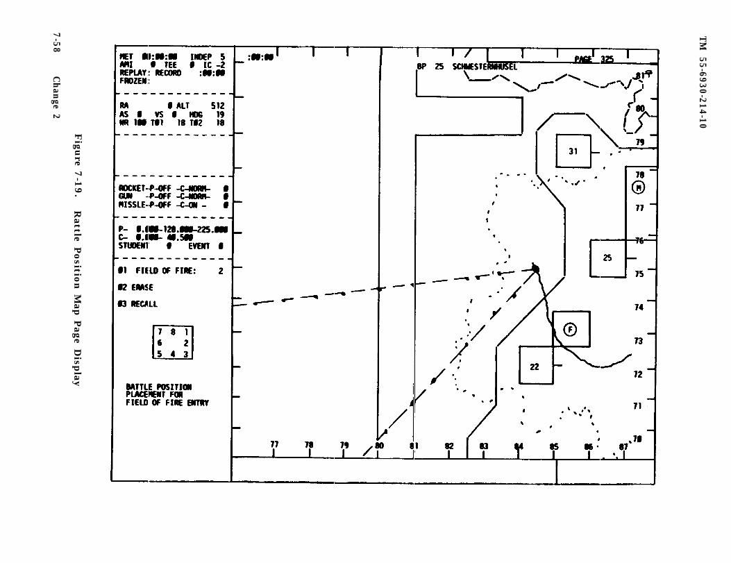
TM
55-6930-214-10
Figu
re 7-1
9.
Rattle P
ositio
n M
ap P
age Disp
lay
7-5
8C
han
ge 2
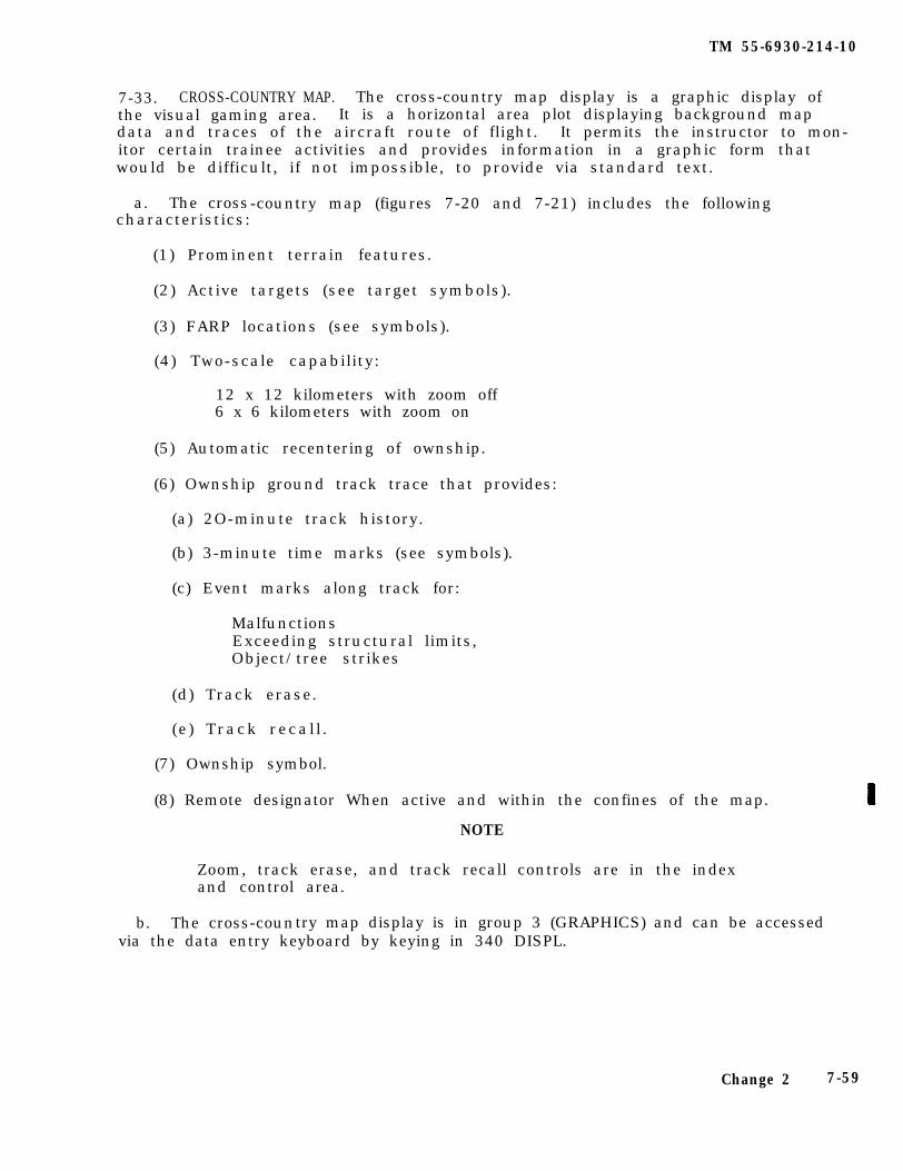
TM 55-6930-214-10
7-33. CROSS-COUNTRY MAP. The cross-country map display is a graphic display ofthe visual gaming area. It is a horizontal area plot displaying background mapdata and traces of the aircraft route of flight. It permits the instructor to mon-itor certain trainee activities and provides information in a graphic form thatwould be difficult, if not impossible, to provide via standard text.
a. The cross-country map (figures 7-20 and 7-21) includes the followingcharacteristics:
(1) Prominent terrain features.
(2) Active targets (see target symbols).
(3) FARP locations (see symbols).
(4) Two-scale capability:
12 x 12 kilometers with zoom off6 x 6 kilometers with zoom on
(5) Automatic recentering of ownship.
(6) Ownship ground track trace that provides:
(a) 2O-minute track history.
(b) 3-minute time marks (see symbols).
(c) Event marks along track for:
MalfunctionsExceeding structural limits,Object/tree strikes
(d) Track erase.
(e) Track recall .
(7) Ownship symbol.
(8) Remote designator When active and within the confines of the map.
NOTE
Zoom, track erase, and track recall controls are in the indexand control area.
b. The cross-country map display is in group 3 (GRAPHICS) and can be accessedvia the data entry keyboard by keying in 340 DISPL.
Change 2 7-59
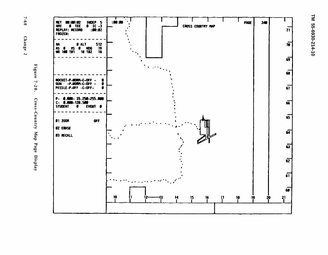
TM 55-6930-214-10
Figu
re 7-2
0.
Cro
ss-Country
Map
Page D
isplay
7-6
0C
han
ge 2
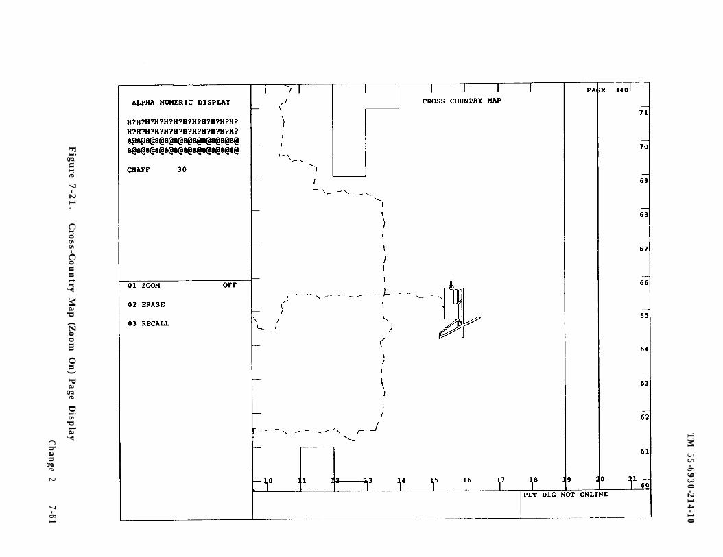
TM
55-6930-214-10
Figu
re 7-2
1.
Cro
ss-Country
Map
(Zoom
On) P
age Disp
layCh
ange 2
7-61
TM 55-6930-214-10
C. The instructors can use the cross-country map displays to:
Monitor trainee enroute location and routeMaintain general orientation in visual gaming areaMonitor relationship between ownship location and threatRecord locations of object or tree strikesRecord periods of intervisibility and exposure to threat weaponsShow malfunction occurrencesCritique/debrief trainee performance via hardcopy feature
d. When intervisibility exists between the ownship and the target(s). the targetsymbol is shown in high intensity on the cross-country map.
7-34. TACTICAL INSTRUMENT GAMING AREA DISPLAY. The tactical instrument gamingarea display is a graphic overview of the instrument navigational and approachfacilities available in the gaming area. It provides the instructor with thecapability of monitoring the trainee tactical Instrument route of flight.
a. The display (figures 7-22 and 7-23) includes the following characteristics:
(1) Symbology for nondirectional radio beacons.
(2) Symbology for GCA facilities.
(3) Two scales with a zoom capability (when zoom is on, CRT main page area iscleared, except for ownship symbol):
40 x 32 kilometers with zoom off6 x 6 kilometers with zoom on
(4) Ownship ground track trace which provides:
(a) 20-minute track history.
(b) 3-minute time marks.
(c) Event marks along track for:
MalfunctionsExceeding structural limitsObject/tree strikes
(d) Track erase.
(e) Track recall.
(5) GCA select NO.
(6) GCA cancel.
(7) Activate NDB number.
(8) Fail NDB number.
(9) Remote designator.
7-62 Change 2
TM
55-6930-214-10
Figu
re 7-2
2.
Tactical In
strum
ent G
amin
g Area P
age Disp
lay
Ch
ange 2
7-63
TM
55-6930-214-10
7-6
4
Ch
ange
2
Figu
re 7-2
3.
Tactical In
strum
ent G
amin
g Area (Z
oom
On) P
age Disp
lay
TM 55-6930-214-10
b. The display is in group 3 (GRAPHICS) and can be accessed via the data entrykeyboard by keying in 341 DISPL.
C. Instructors can use the displays to:
Monitor trainee instrument route of flightNote locations of object or tree strikesShow malfunction occurrences during instrument flightLocate and vector ownship to GCA facilitySelect or cancel GCA facilityCritique/debrief trainee performance via remote display or hardcopy featureActivate/fail NDB sites
7-35. MAP SYMBOLOGY. The map symbols shown on the CRT map displays are graphicrepresentations of specific items or objects. They have been provided to enhancethe informational value of the map displays and provide timely feedback to theinstructor.
a. Types of symbols include the following:
TargetsTarget siteFARP locationNavigation aidsOwnship3-minute time markMalfunctionCrashProminent pointsK i l lRemote designator with 1 km markersIllumination round burstWeapon impact points
b. The map symbology CRT display (figure 7-24) lists and shows all the availablesymbols. The symbols appear on the following graphic display pages:
Target site overview (page 540)Target site pathway detailed display (page 540)Battle position target site (pages 541 - 575)Cross-country map (page 340)Tactical instrument gaming area (page 341)GCA (pages 350 - 351)Gaming area map (page 343)Battle positions (pages 301 - 334)Ownship weapons scoring (page 597)Remote designator (page 582)
The map symbology page is in group 3 (GRAPHICS) and can be accessed via thedata entry keyboard and keying in 342 DISPL. (Figure 7-25 illustrates the mapsymbols employed in the CMS, shown larger than actual size to aid inidenti f ication.)
Change 2 7-65
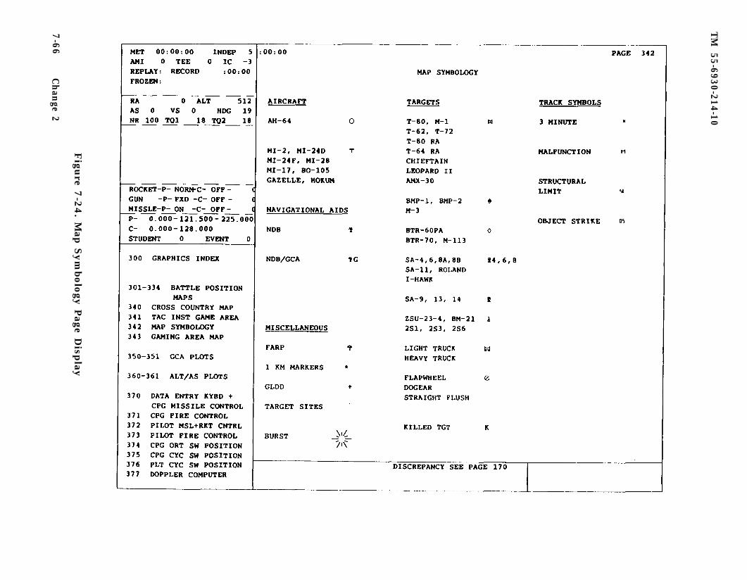
TM
55-6930-214-10
Figu
re 7-2
4. M
ap S
ym
bolo
gy P
age Disp
lay
7-6
6C
han
ge 2
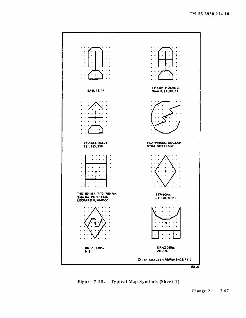
TM 55-6930-214-10
Figure 7-25. Typical Map Symbols (Sheet 1)
Change 2 7-67
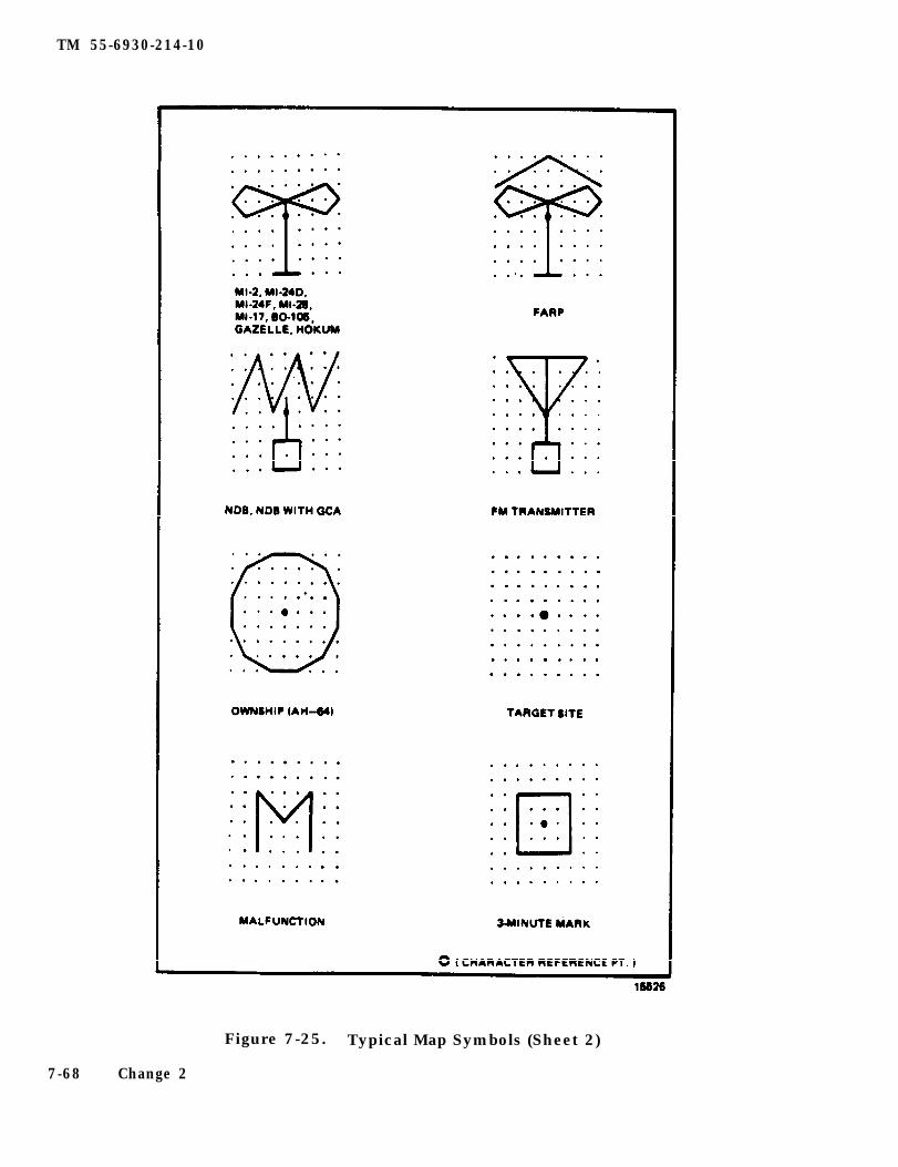
TM 55-6930-214-10
Figure 7-25. Typical Map Symbols (Sheet 2)
7-68 Change 2
TM 55-6930-214-10
d. The symbols art used to:
Identify target types and sitesIdentify FARP landing areasIdentify PM transmitters, NDB’s, and GCA sitesIdentify ownship locationIdentify locations of malfunction occurrencesIdentify location and cause of crashesObtain tine checks along route of flightIdentify the 1 km points on the range lines on the ownship weapon scoring
Identify the burst location (illumination round only)Identify the weapon impact locations
and remote designation pages.
7-36. GCA PLOTS. The ground-controlled approach (GCA) display is a stylizedrepresentation of the precision approach radar (PAR) glideslope and centerline.The simulated progress along both paths is displayed using a symbol for the ownshipand a track trace. The GCA display provides computer-generated command informationrequired to conduct the final controller portion of a simulated GCA approach. In-structions appearing in the command box on the CRT reflect simulated aircraftposition with respect to the final approach path to the runway. The displayprovides the instructor with a graphic display of the aircraft location in relationto the glideslope and centerline for the approach runway and the alphanumericalcommands to be used by the instructor to conduct the GCA.
a. The GCA displays are on CRT pages 350 (figure 7-26) and 351 (figure 7-27).These displays include the following information and characteristics:
Glideslope and centerline deviation trackGCA commands - correction to course, corrections to glideslopeTwo scale displays: 10- and 2-nmiGCA selection and cancellation in index and control area
b. The GCA display pages are in group 3 (GRAPHICS) and can be accessed by keyingin 350 DISPL via the data entry keyboard. Access CRT page 351 by depressing PAGEFWD or by keying 351 DISPL. Before calling up the GCA display, the instructor canuse the tactical instrument gaming area map to vector the simulated aircraft intothe approach course corridor. The NDB can also be used to vector the aircraft intothe approach corridor. The GCA window or corridor is approximately a 4500-footsquare at 10 nmi on the approach side of the runway extended centerline. The in-structor can use the GCA display to conduct GCA approaches to the airfield, to sup-plement information derived from cockpit instruments and the status area display,and to critique/debrief trainee GCA performance via the remote display or the hard-copy feature.
C. There is only one GCA available, facility No. 52, runway 20, at the airbase.When CRT page 350 is displayed, the index and control area contains command refer-ence lines. To activate the GCA program, key in 01 TAB 52 ENTER on the data entrykeyboard. Line 02 permits the instructor to cancel the GCA program. GCA can alsobe activated by using page 602 line 52 or page 341 line 4. Alternately, the GCAprogram automatically turns off when the ownship is 15 km outbound from the base.
Change 2 7-69
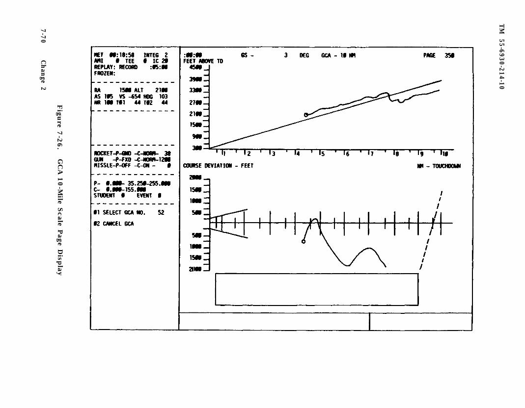
TM
55-6930-214-10
Figu
re 7-2
6.
GC
A 1
0-M
ile Scale P
age Disp
lay
7-7
0C
han
ge 2
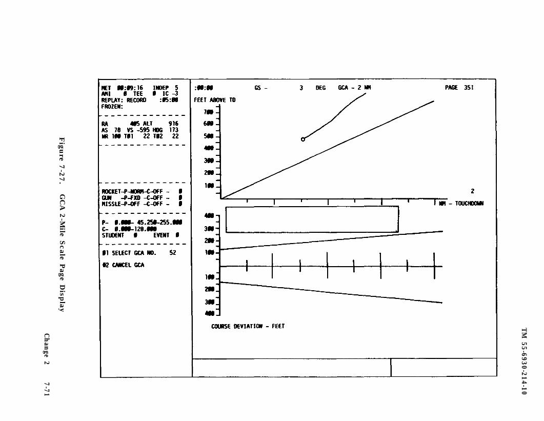
TM
55-6930-214-10
Figu
re 7-2
7.
GC
A 2
-Mile S
cale Page D
isplay
Ch
ange 2
7-71
TM 55-6930-214-10
NOTE
The instructor must ensure that ownship penetrates the upper GCAbox displayed on page 341 to receive command information in thecommand box on GCA pages.
7-37. ALTITUDE/AIRSPEED PLOTS. The altitude/airspeed plots graphically depict ahistory of aircraft performance related to altitude and airspeed versus distance.The altitude is measured and recorded above obstacles from the surface to a maximumof 200 feet AGL. Airspeed is IAS recorded up to normal cruise speed of the actualaircraft. Distance is selectable by the instructor in two scales. Distance ismeasured in terms of cumulative movement without respect to direction of such move- ment .
a. Major characteristics of the plots (sham in figures 7-28 and 7-29) include:
Altitude above ground versus distanceIndicated airspeed versus distanceTwo selectable plot scales: 6- and l-km
b. The airspeed/altitude plots are in group 3 (GRAPHICS) and art accessed viathe data entry keyboard by keying in CRT page 360 or CRT page 361. Typical uses ofthe altitude/airspeed plots include:
(1) Monitoring trainee altitude control during enroute navigation:
NOE navigation routesTactical instrument routes (under 200 feet only)
(2) Monitoring trainee altitude control in the firing position.
(3) Monitoring trainee airspeed control throughout training missions.
(4) Debriefing/critiquing trainee performance via the hardcopy feature.
7-38. CONTROL PANEL CRT DISPLAYS. The control panel CRT displays are facsimilerepresentations of aircraft cockpit control panels. These displays include thepanel title, title and position of each switch, setting of each control, status ofeach indicator, and value of each readout on the panel represented. The eight con-trol panel displays and their CRT page numbers are:
CPG missile control panel and data entry keyboard (page 370) (figure 7-u))CPG fire control panel (page 371) (figure 7-31)Pilot missile control panel (page 372) (figure 7-32)Pilot fire control panel (page 373) (figure 7-33)CPG ORT panel (page 374) (figure 7-34)CPG cyclic control switches (page 375) (figure 7-35)Pilot cyclic control switches (page 376) (figure 7-36)Doppler computer display unit (page 377) (figure 7-37)
a. The control panel CRT displays art in group 3 (GRAPHICS) and are accessed viathe data entry keyboard by calling up CRT pages 370 through 377. (Refer to thelist and associated page numbers above.)
7-72 Change 2
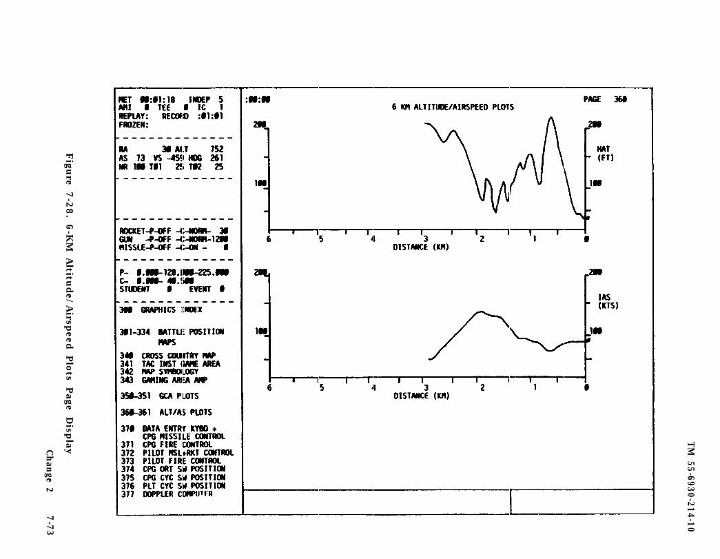
TM
55-6930-214-10
Figu
re 7-2
8.
6-K
M A
ltitude/
Airsp
eed Plo
ts Page
Disp
layCh
ange 2
7-7
3
TM
55-6930-214-10
7-74
Figu
re 7-2
9.
Ch
ange 2
1-K
M A
ltitude/
Airsp
eed P
lots P
age Disp
lay
TM
55-6930-214-10
Figu
re 7-3
0.
CPG
Missile C
ontro
l Pan
el Page D
isplay
Ch
an
ge
2 7
-75
TM
55-6930-214-10
Figu
re 7-3
1.
CPG
Fire C
on
trol P
anel P
age Disp
lay
7-76C
han
ge 2
TM
55-6930-214-10
Figu
re 7-3
2.
Pilo
t M
issile C
ontro
l Pan
el Page
Disp
layCh
ange 2
7-7
7
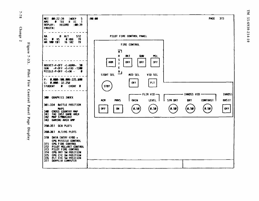
TM
55-6930-214-10F
igure 7
-33.
Pilo
t Fire C
on
trol P
anel P
age Disp
lay
7-7
8C
han
ge 2
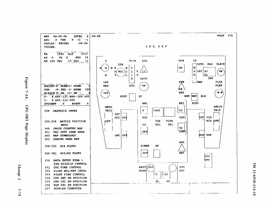
TM
55-6930-214-10
Figu
re 7-3
4.
CPG
OR
T P
age Display
Ch
ange 2
7-7
9
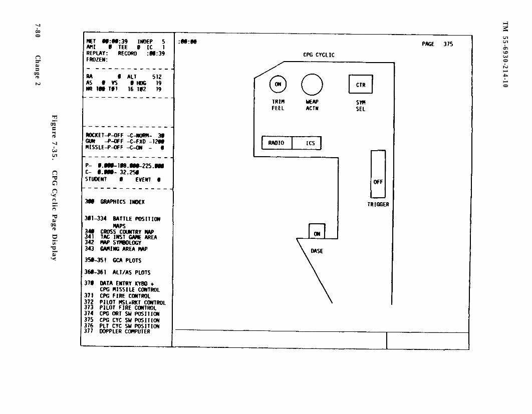
TM
55-6930-214-10
Figu
re 7-3
5.
CPG
Cyclic P
age Disp
lay
7-80C
han
ge 2
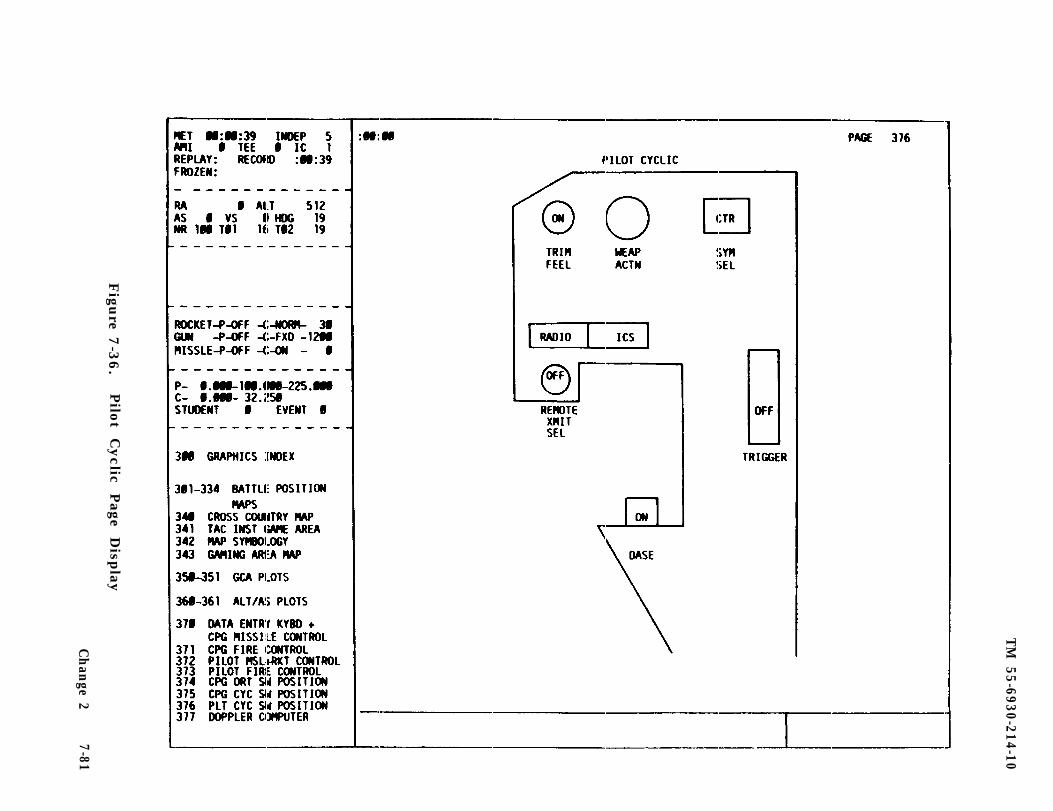
TM
55-6930-214-10
Figu
re 7-3
6.
Pilo
t C
yclic
Page
Disp
lay
Ch
ange 2
7-81
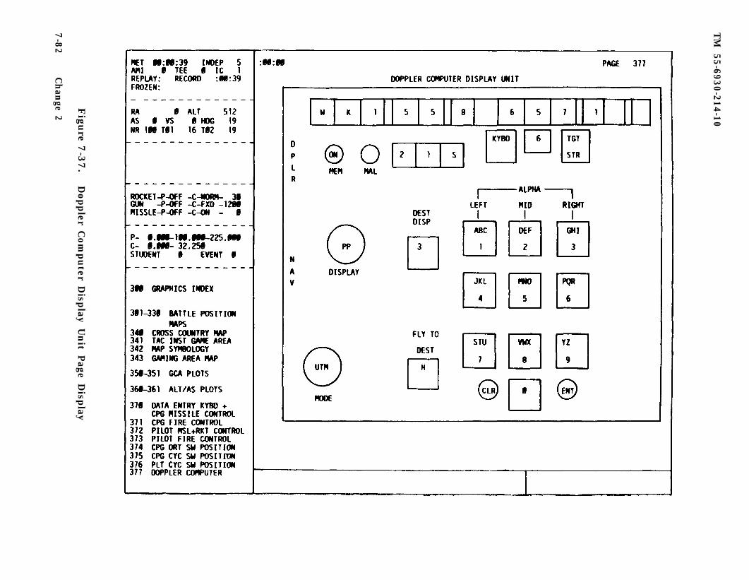
TM
55-6930-214-10
Figu
re 7-3
7.
Doppler C
om
puter D
isplay
Un
it Page D
isplay
7-8
2C
han
ge 2
TM 55-6930-214-10
b. These panel displays are updated continuously to indicate the changes thathave occurred in the represented cockpit panel.
c. These panel displays permit the instructor to monitor switches, controls, andindicators in the trainee cockpits that might otherwise not be viewable; analyzetrainee performance of procedures related to use of each panel; determine if panelswitch, controls, and indicators are correct; and provide Doppler inputs to thepilot during independent mode operations.
7-39. TARGET ENGAGEMENT EXERCISE. The target engagement exercise (TEE) is a fea-ture that automatically inserts events associated with the engagement of hostiletargets in response to certain relationships between ownship and the target andtrainees performance. The events include initiation of targets movement, targetsfiring at ownship, activation of hostile radar, weapons hits on ownship. and systemmalfunctions resulting from hits. The factors that trigger these events includealtitude, line-of-sight exposure, range to target, and release of ownship weapons.Up to three of these triggering contingencies may be required to activate anevent. When the specified insertion contingencies have been met, the target eventoccurs in the manner programmed for it without instructor intervention.
a. There are 20 preprogrammed TEE’s available for training. They are availableto both the pilot and CPG instructors in the independent and the integrated modes.Each TEE can include up to ten targets. Five of the targets are capable of movingover predetermined routes. The other five are on fixed sites and do not travel.All targets capable of firing weapons can articulate and fire at the ownship. Wea-pons systems with radar are capable of electronic emissions that activate the radarwarning receiver on the ownship. Aircraft survivability equipment (ASE) aboard theownship is capable of foiling the respective type of weapons system.
b. All threat weapons systems are modeled after real-world weapons and performaccordingly. Preprogramned hostile events in a TEE are controlled via a sophisti-cated threat algorithm once the triggering contingencies have been met. For exam-ple, when intervisibility exists between the ownship and a hostile target and theownship is within the effective range of the threat, the threat begins the acquisi-tion process. If the threat is employing radar, it triggers the ownship radarwarning receiver. If line-of-sight exposure is maintained, the threat engages theownship. Hits on the ownship and resultant damage (malfunctions) are preprogrammedfor each target in the TEE. Breaking line-of-sight (remasking) disrupts the threatacquisition process. Engagement and destruction of the threat also terminate theacquisition process.
c. Trainee (student) performance data is automatically stored during target en-gagements. This data is on CRT pages 595-596 and can be displayed at the IOS andretrieved in hardcopy. Additionally, data related to threat acquisition of theownship is automatically recorded and can be displayed by calling up CRT page 594.
d. Preprogrammed TEE sets are indexed on CRT pages 500A and 500B. IndividualTEE's are described in CRT pages 501 through 520. (See figure 7-38.) This page isaddressed via the data entry keyboard on the console control panel. A TEE set canbe reviewed on the CRT by keying in the 3-digit page number and depressing DISPL.The displayed TEE set provides all the data related to the targets for that set.This data includes target types, location, presence or absence of hostility, direc-tion of travel, hits and associated malfunctions, and triggering contingenciesapplicable to each target. To enter a TEE set into the simulation, key in the
Change 2 7-83
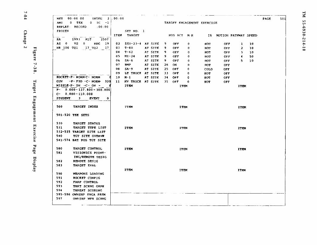
TM
55-6930-214-10F
igure 7
-38.
Target E
ngagem
ent E
xercise Page D
isplay
7-84C
han
ge 2
TM 55-6930-214-10
3-digit page number via the keyboard and depress ENTER. The TEE set is nowavailable. When the triggering contingencies are met, the set activates, only oneTEE set can be entered into simulation at a time. The simulator need not be infreeze to enter TEE sets. Entering an additional TEE set during trainingautomatically deletes the previously entered set.
e. After a TEE has been entered, various aspects of it can be reviewed by dis-playing other pages related to targets. Target status CRT page 530 summarizestargets and their related activity. Target site overview CRT page 540 graphicallydepicts all 99 target sites and indicates, with symbols, which sites have beenselected with the current TEE. A target site detailed display, which provides aspecific target site and the routes of travel from the site, can be called up byusing the index and control area on CRT page 540. Detailed firing position sitesthat graphically depict threat targets visible from that specific firing positionare on CRT pages 541 through 575.
f . Student/trainee engagement performance data are summaries of engagement ac-tivity and are on CRT pages 595-596.
g. Threat acquisition data are summaries of hostile weapons activity and are onCRT page 594.
h. TEE sets are used to:
Permit preprogramming threat activities to establish a hostile environmentReduce instructor workloadProvide a greater degree of standardization in the presentation of threat
situationsPermit an increased degree of control over the content of trainingPermit rapid rearrangement of threat activityPermit expansion of the battlefield environment and flexibility in
structuring training scenarios
7-40. TARGET STATUS. The target status page provides status information for tar-gets that are currently entered in the simulation. (Table 7-9 defines the dataelements displayed on the page.)
a. Characteristics of the target status page (figure 7-39) include a summary ofthe most recently activated TEE or manually inserted targets, and a depiction of upto 10 targets (ten is the maximum number of active targets).
b. The target status page is in group 5 (TARGETS) and can be accessed via thedata entry keyboard by calling up CRT page 530.
c. The target status page is used to determine:
Number and type of active targetsSite location of active targetsWhich targets are hostile and which malfunctions are associated with a hitWhich targets will move and their path and speedIR signature type for each target
Change 2 7-85
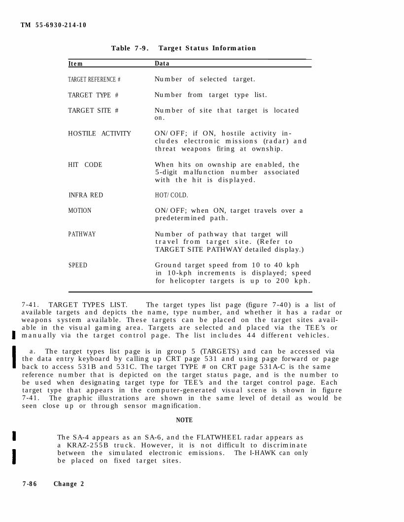
TM 55-6930-214-10
Table 7-9. Target Status Information
Item Data
TARGET REFERENCE # Number of selected target.
TARGET TYPE # Number from target type list.
TARGET SITE # Number of site that target is locatedon.
HOSTILE ACTIVITY ON/OFF; if ON, hostile activity in-cludes electronic missions (radar) andthreat weapons firing at ownship.
HIT CODE
INFRA RED HOT/COLD.
MOTION ON/OFF; when ON, target travels over apredetermined path.
PATHWAY
When hits on ownship are enabled, the5-digit malfunction number associatedwith the hit is displayed.
Number of pathway that target willtravel from target site. (Refer toTARGET SITE PATHWAY detailed display.)
SPEED Ground target speed from 10 to 40 kphin 10-kph increments is displayed; speedfor helicopter targets is up to 200 kph.
7-41. TARGET TYPES LIST. The target types list page (figure 7-40) is a list ofavailable targets and depicts the name, type number, and whether it has a radar orweapons system available. These targets can be placed on the target sites avail-able in the visual gaming area. Targets are selected and placed via the TEE’s ormanually via the target control page. The list includes 44 different vehicles.
a. The target types list page is in group 5 (TARGETS) and can be accessed viathe data entry keyboard by calling up CRT page 531 and using page forward or pageback to access 531B and 531C. The target TYPE # on CRT page 531A-C is the samereference number that is depicted on the target status page, and is the number tobe used when designating target type for TEE’s and the target control page. Eachtarget type that appears in the computer-generated visual scene is shown in figure7-41. The graphic illustrations are shown in the same level of detail as would beseen close up or through sensor magnification.
NOTE
The SA-4 appears as an SA-6, and the FLATWHEEL radar appears asa KRAZ-255B truck. However, it is not difficult to discriminatebetween the simulated electronic emissions. The I-HAWK can onlybe placed on fixed target sites.
7-86 Change 2
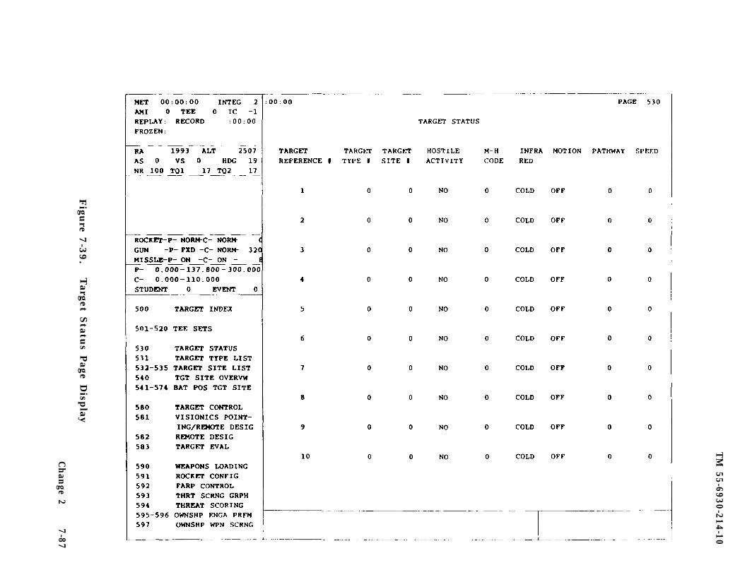
TM
55-6930-214-10
Figu
re 7-3
9.
Target S
tatus P
age Disp
lay
Ch
ange 2
7-87
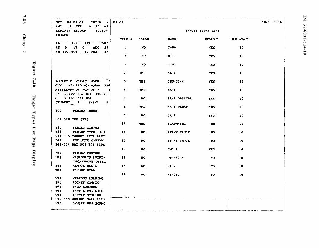
TM
55-6930-214-10
Figu
re 7-4
0.
Target T
ypes L
ist Page D
isplay
7-88C
han
ge 2
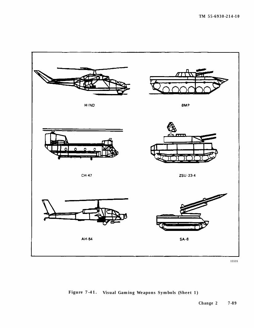
TM 55-6930-214-10
15535
Figure 7-41. Visual Gaming Weapons Symbols (Sheet 1)
Change 2 7-89
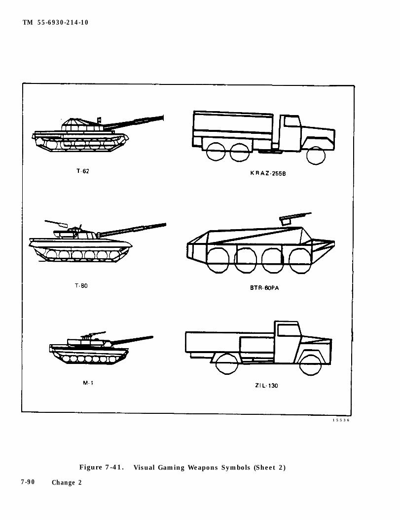
TM 55-6930-214-10
1 5 5 3 6
Figure 7-41. Visual Gaming Weapons Symbols (Sheet 2)
7-90 Change 2
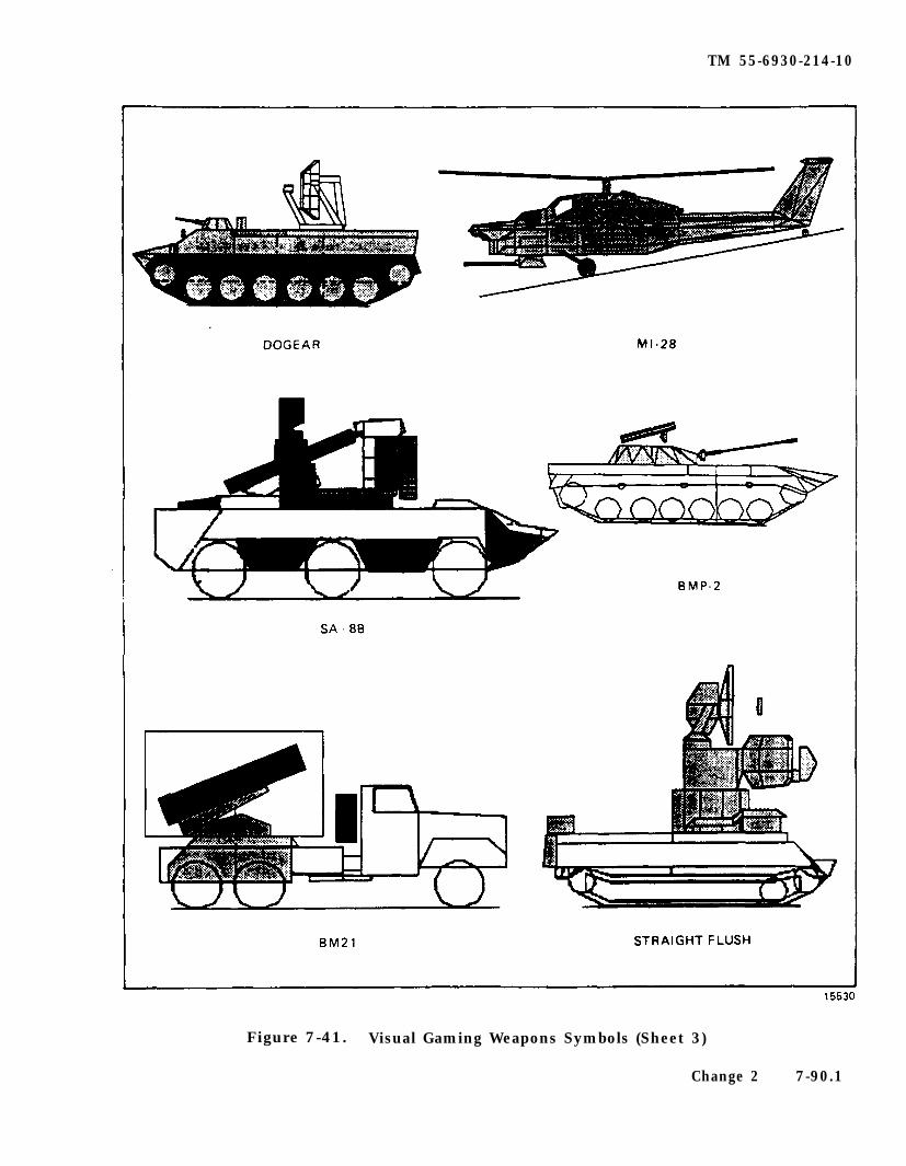
TM 55-6930-214-10
Figure 7-41. Visual Gaming Weapons Symbols (Sheet 3)
Change 2 7-90.1
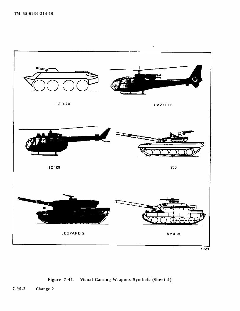
TM 55-6930-214-10
Figure 7-41. Visual Gaming Weapons Symbols (Sheet 4)
7-90.2 Change 2
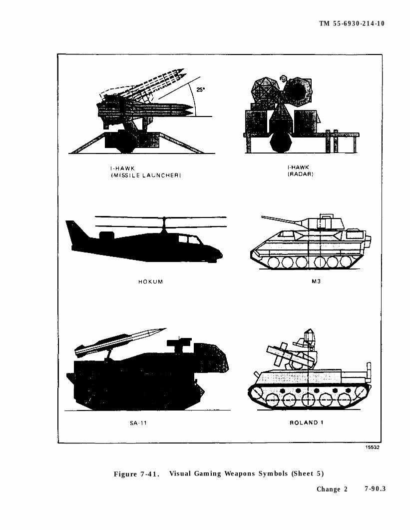
TM 55-6930-214-10
Figure 7-41. Visual Gaming Weapons Symbols (Sheet 5)
Change 2 7-90.3
TM 55-6930-214-10
Figure 7-41. Visual Gaming Weapons Symbols (Sheet 6)
7-90.4 Change 2
TM 55-6930-214-10
Figure 7-41. Visual Gaming Weapons Symbols (Sheet 7)
Change 2 7-90.5
TM 55-6930-214-10
Figure 7-41. Visual Gaming Weapons Symbols (Sheet 8)
7-90.6 Change 2
TM 55-6930-214-10
b. The target types list page is used to identify the types of available tar-gets. to select and enter targets into the simulation, and to determine whether atarget type has radar and/or weapons.
7-42. TARGET SITES LIST. The target sites list page (figure 7-42) is an informa-tion list for the 99 target sites In the visual gaming area. The list provides thesite name, site number, and site position in UTM coordinates. The site number isthe reference number used to designate a site when preparing TEE’s or when usingthe manually inserted targets via the target control page.
get sites (e.g., sites that have specific, preprogrammed ground or airborne path-ways that targets will follow when notion is enabled and activated). Fifteen ofthese roving target sites are ground sites (1 through 15) that can accommodate upto five targets each. The targets move on separately numbered paths (1 through 5)and generally follow the same route for approximately 15 kilometers. The remainingfive moving target sites (16 through 20) have been designed for use with aircraft.The airborne sites each have a single flightpath. The aircraft maintains a fixedaltitude (MSL) throughout the route of flight. Hostile aircraft on any movingtarget site have a hostile capability. If ownship enters designed firing cone(approximately ±20O from the threat aircraft CL out to maximum weapon range)hostile helicopters will engage ownship until cone limits are exceeded.
a. The first 20 target sites (01 through 20) have been designated as moving tar-
b. The remaining 79 sites (21 through 99) are fixed target sites. These siteshave no pathways, and targets do not travel when positioned on them. When targetsare positioned at fixed sites, they can be designated as hostile; in that case,both radar and weapons are directed against the ownship when hostile activities areselected. Ground systems rotate and point toward the ownship prior to firing.Hostile aircraft on fixed sites (excluding MI-24D, F) will come to 25 foot hover,turn, and engage ownship until LOS is broken. The TEE and the manual targetcontrol page are used to establish the initial criteria for hostile threat activityand ownship hits. These criteria are evaluated in a threat algorithm (refer toTHREAT WEAPONS SCORING) to determine the outcome of the threat activity.
c. The target sites list page is in group 5 (TARGETS) and can be accessed viathe data entry keyboard by calling up CRT pages 532 through 535. The CRT page isused to determine target sites names and positions/locations (UTM coordinates),moving target sites, and airborne target sites.
7-43. TARGET SITES OVERVIEW. The target sites page (figures 7-43 and 7-44) is agraphic picture of the simulated visual gaming area indicating each target sitelocation by number within a 40- by 32-km area. When a target has been selected andpositioned on a target site. either manually or via activation of a TEE, a symbolappears on the target site overview identifying the specific type of target. Figure7-45 shows the symbols used to identify the different targets from the target list.Figure 7-45 also shows symbols used for FARP’s, NDB’s, GCA’s, ownship, malfunctions,and 3-minute index marks. In addition to appearing on the target site overviewdisplay, these symbols also appear on other graphic CRT pages (e.g.. cross-countryraps, battle position target site maps, etc.).
a. The target site overview page (figure 7-43) is in group 5 (TARGETS) and canbe accessed via the data entry keyboard and keying in 540 DISPL.
Change 2 7-91
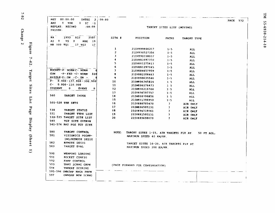
TM
55-6930-214-10
Figu
re 7-4
2.
Target
Sites
List
Page
Disp
lay (S
heet
1)
7-92C
han
ge 2
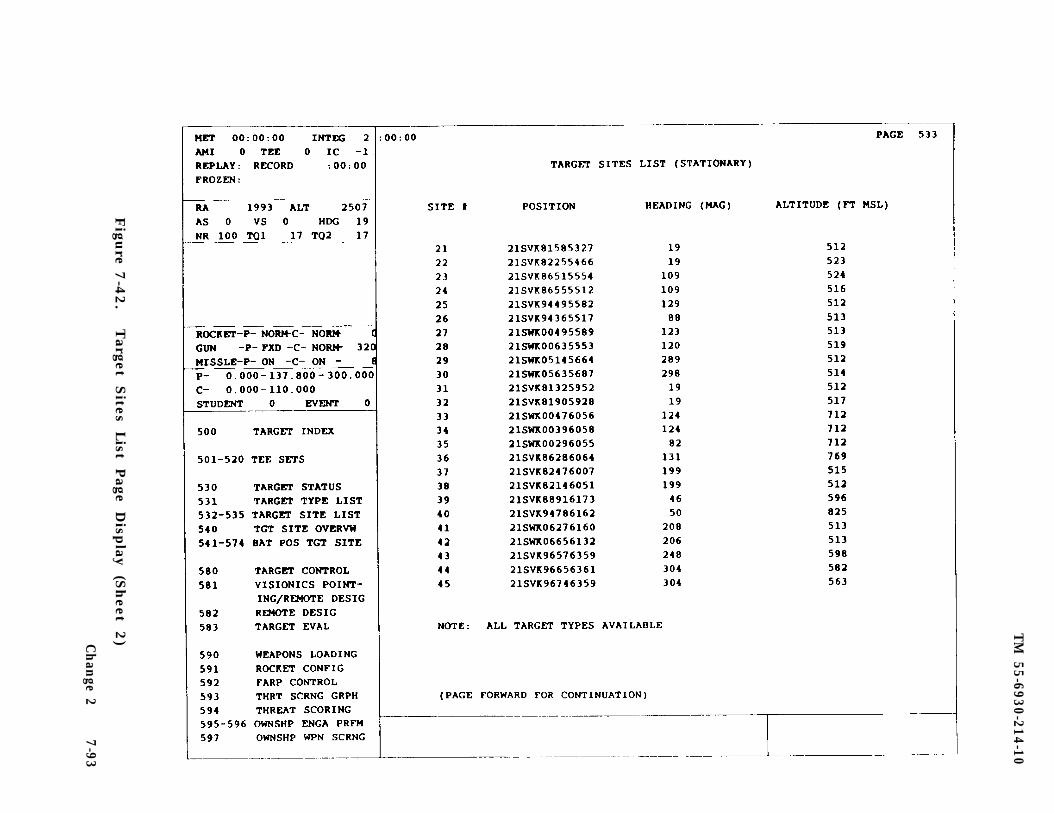
TM
55-6930-214-10
Figu
re 7-4
2.
Target
Sites
List
Page
Disp
lay (S
heet
2)C
han
ge 27-93
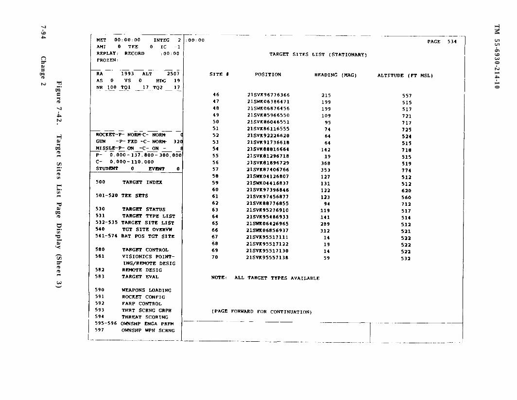
TM
55-6930-214-10
7-94
Figu
re 7-4
2.
Target
Sites
List
Page
Disp
lay (S
heet
3)
Ch
ange 2
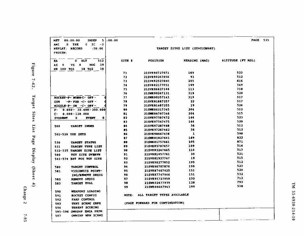
TM
55-6930-214-10
Figu
re 7-4
2.
Target
Sites
List
Page
Disp
lay (S
heet
4)C
han
ge 27-95
TM
55-6930-214-10
Figu
re 7-4
3.
Target S
ites Overv
iew P
age Disp
lay
7-9
6C
han
ge 2
TM
55-6930-214-10
Figu
re 7-4
4.
Target S
ites Overv
iew (Z
oom
On
) Page D
isplay
Ch
ange 2
7-97
TM 55-5930-214-10
Figure 7-45. Typical Target Symbols (Sheet 1)
7-98 Change 2
TM 55-6930-214-10
Figure 7-45. Typical Target Symbols (Sheet 2)
Change 2 7-99
TM 55-6930-214-10
b. Target site pathway detailed displays can be called up for display via thedata entry keyboard and the reference numbers in the index and control area whentarget site overview CRT page 540 is displayed (e.g., 01 TAB 05 ENTER, displays thepathway, If any. associated with target number 5). These pathways are used withTEE’s and with the manual target control page to designate the path to be traveledby a specific type target (e.g., T-80. T-62, etc.). When a target s i te i s i sentered, all target reference numbers disappear from the display. To return thetarget reference numbers. key in 03 ENTER. This recalls all sites to the displayand deletes the pathway previously displayed. Command 03 is used to recall allsites and terrain markings.
c. The target site overview page is used to:
Determine relative location of each target site within visual gaming areaDetermine which targets art activeDetermine type targets that have been placed on the 10 active target sitesCall up and display target site pathway detailed displays
7-44. BATTLE POSITION TARGET SITES. The battle position target site (availabletarget sites reference) CRT pages (figure 7-46) provide graphic data related tobattle/firing positions and associated target sites and provide the instructor witha 12- by 12-km graphic overview of the target engagement area of interest.
a. There are 34 designated battle positions included in the visual gaming area.These battle positions include from one to tight firing positions each. The battlepositions are designed in l-kilometer squares and can be entered from only one sideof the square kilometer. The battle position is composed of relatively high terrainthat overlooks target engagement areas (low terrain containing target sites). With-in each battle position are nap-of-the-earth (NOE) routes leading to the firingpositions.
b. Battle position target sites are always oriented on the CRT display so thatnorth is up. Bach battle position target site shows the battle position by numberand all of the target sites within its 10-kilometer range. Since each battle posi-tion has one or more firing positions. several fields-of-fire are available to thetrainee. Bach battle position has been designed with tight selectable fields-of-fire for the Instructor to choose from when viewing the target sites in the targetengagement areas.
cessedThe battle position target site pages are in group 5 (TARGETS) and can be ac-via the data entry keyboard (CRT pages 541-574). In the index and control
area of the CRT page when battle position target site maps art displayed, controlreference numbers are provided to permit selection of fields-of-fire. Each battleposition has only one entrance side. shown on the map with an index. Starting inthe upper right-hand corner of the battle position, the fields-of-fire are numbered1 through 8 in a clockwise direction. In the control area, reference number 01 isthe command for selecting the FIELD OF FIRE number. Reference numbers 02 and 03 areaircraft TRACK ERASE and TRACK RECALL, respectively. Reference number 01 can beentered via the data entry keyboard while the map is displayed (e.g., 01 TAR 6ENTER) and causes the viewing direction of the field-of-fire to change for the spe-cified battle position. As fields-of-fire art selected (advanced), the map automa-tically repositions in relation to the battle position to maintain the maximumfield-of-view in the direction of the field-of-fire (i.e., when field-of-fire 6is selected, the battle position is displayed on the left side of the CRT page and
c .
7-100 Change 2
TM
55-6930-214-10
Figu
re 7-4
6.
Battle P
ositio
n T
arget Site M
ap P
age Disp
lay
Ch
ange 2
7-101
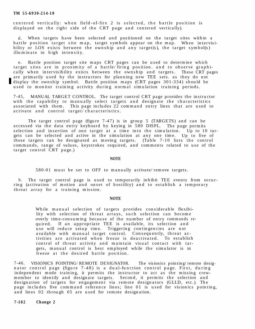
TM 55-6930-214-10
centered vertically: when field-of-fire 2 is selected, the battle position isdisplayed on the right side of the CRT page and centered vertically).
d. When targets have been selected and positioned on the target sites within abattle position target site map, target symbols appear on the map. When intervisi-bility or LOS exists between the ownship and any target(s), the target symbol(s)illuminate in high intensity.
e. Battle position target site maps CRT pages can be used to determine whichtarget sites are in proximity of a battle/firing position. and to observe graphi-cally when intervisibility exists between the ownship and targets. These CRT pagesare primarily used by the instructors for planning new TEE sets. as they do notdisplay the ownship symbol. Battle position maps (CRT pages 301-334) should beused to monitor training activity during normal simulation training periods.
7-45, MANUAL TARGET CONTROL. The target control CRT page provides the instructorwith the capability to manually select targets and designate the characteristicsassociated with them. This page includes 22 command entry lines that are used toactivate and control target/characteristics.
The target control page (figure 7-47) is in group 5 (TARGETS) and can beaccessed via the data entry keyboard by keying in 580 DISPL. The page permitsselection and insertion of one target at a time into the simulation. Up to 10 tar-gets can be selected and active in the simulation at any one time. Up to five ofthese targets can be designated as moving targets. (Table 7-10 lists the controlcommands, range of values, keystrokes required, and comments related to use of thetarget control CRT page.)
NOTE
580-01 must be set to OFF to manually activate/remove targets.
b. The target control page is used to temporarily inhibit TEE events from occur-ring (activation of motion and onset of hostility) and to establish a temporarythreat array for a training mission.
NOTE
While manual selection of targets provides considerable flexibi-lity with selection of threat arrays, such selection can becomeoverly time-consuming because of the number of entry commands re-quired. If an appropriate TEE is available, its selection anduse will reduce setup time. Triggering contingencies are notavailable with manual target control. Consequently, threat ac-tivities are activated when freeze is deactivated. To establishcontrol of threat activity and maintain visual contact with tar-gets, manual control is best employed while the simulator is infreeze at the desired battle position.
7-46. VISIONICS POINTING/REMOTE DESIGNAT0R. The visionics pointing/remote desig-nator control page (figure 7-48) is a dual-function control page. First, duringindependent mode training, it permits the instructor to act as the missing crew-member to identify and designate targets. Second, it permits the selection anddesignation of targets for engagement via remote designators (GLLD, etc.). Thepage includes five command reference lines; line 01 is used for visionics pointing,and lines 02 through 05 are used for remote designation.
7-102 Change 2
TM
55-6930-214-10
Figu
re 7-4
7. M
anual T
arget Con
trol P
age Disp
lay
Ch
ange 2
7-103
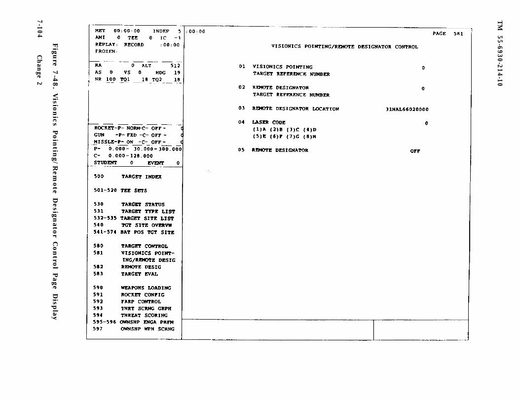
TM
55-6930-214-10
Figu
re 7-4
8. V
ision
ics Poin
ting/
Rem
ote D
esignato
r Con
trol P
age Disp
lay
7-104C
han
ge 2
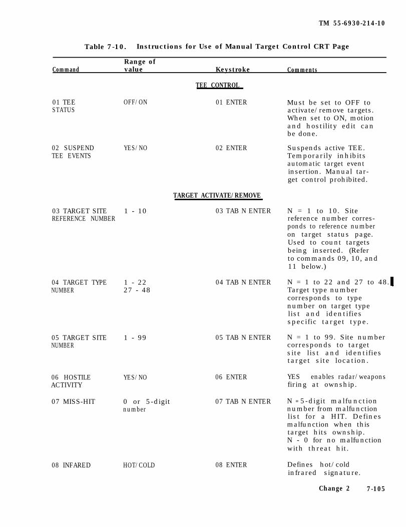
TM 55-6930-214-10
Table 7-10. Instructions for Use of Manual Target Control CRT Page
Range ofCommand value Keystroke Comments
TEE CONTROL
01 TEE OFF/ON 01 ENTER Must be set to OFF toSTATUS activate/remove targets.
When set to ON, motionand hostility edit canbe done.
02 SUSPENDTEE EVENTS
YES/NO
03 TARGET SITE 1 - 10REFERENCE NUMBER
04 TARGET TYPE 1 - 22NUMBER 27 - 48
05 TARGET SITE 1 - 99NUMBER
06 HOSTILEACTIVITY
07 MISS-HIT
08 INFARED HOT/COLD
YES/NO
0 or 5-digitnumber
02 ENTER
TARGET ACTIVATE/REMOVE
03 TAB N ENTER
04 TAB N ENTER
05 TAB N ENTER
06 ENTER
07 TAB N ENTER
08 ENTER
Suspends active TEE.Temporarily inhibitsautomatic target eventinsertion. Manual tar-get control prohibited.
N = 1 to 10. Sitereference number corres-ponds to reference numberon target status page.Used to count targetsbeing inserted. (Referto commands 09, 10, and11 below.)
N = 1 to 22 and 27 to 48. Target type numbercorresponds to typenumber on target typelist and identifiesspecific target type.
N = 1 to 99. Site numbercorresponds to targetsite list and identifiestarget site location.
YES enables radar/weaponsfiring at ownship.
N = 5-digit malfunctionnumber from malfunctionlist for a HIT. Definesmalfunction when thistarget hits ownship.N - 0 for no malfunctionwith threat hit.
Defines hot/coldinfrared signature.
Change 2 7-105
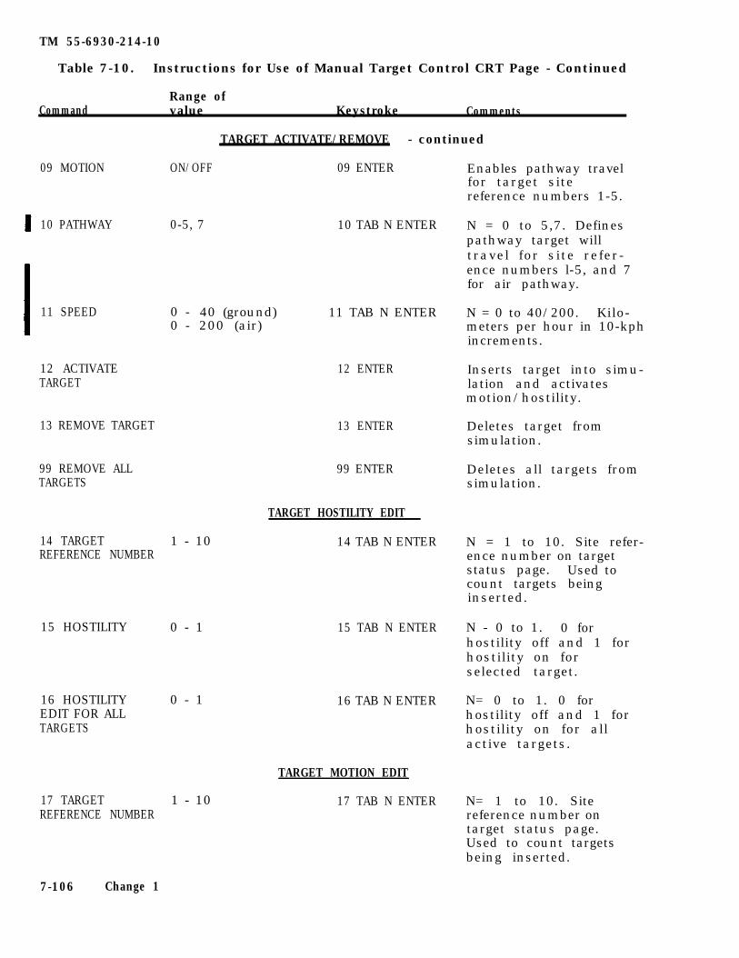
TM 55-6930-214-10
Table 7-10. Instructions for Use of Manual Target Control CRT Page - Continued
Range ofCommand value Keystroke Comments
TARGET ACTIVATE/REMOVE - continued
09 MOTION
10 PATHWAY
11 SPEED
12 ACTIVATETARGET
13 REMOVE TARGET
99 REMOVE ALLTARGETS
14 TARGETREFERENCE NUMBER
15 HOSTILITY
ON/OFF 09 ENTER
0-5, 7 10 TAB N ENTER
0 - 40 (ground)0 - 200 (air)
1 - 10
0 - 1
16 HOSTILITY 0 - 1EDIT FOR ALLTARGETS
17 TARGET 1 - 10REFERENCE NUMBER
11 TAB N ENTER
12 ENTER
13 ENTER
99 ENTER
TARGET HOSTILITY EDIT
14 TAB N ENTER
15 TAB N ENTER
16 TAB N ENTER
TARGET MOTION EDIT
17 TAB N ENTER
Enables pathway travelfor target sitereference numbers 1-5.
N = 0 to 5,7. Definespathway target willtravel for site refer-ence numbers l-5, and 7for air pathway.
N = 0 to 40/200. Kilo-meters per hour in 10-kphincrements.
Inserts target into simu-lation and activatesmotion/hostility.
Deletes target fromsimulation.
Deletes all targets fromsimulation.
N = 1 to 10. Site refer-ence number on targetstatus page. Used tocount targets beinginserted.
N - 0 to 1. 0 forhostility off and 1 forhostility on forselected target.
N= 0 to 1. 0 forhostility off and 1 forhostility on for allactive targets.
N= 1 to 10. Sitereference number ontarget status page.Used to count targetsbeing inserted.
7-106 Change 1
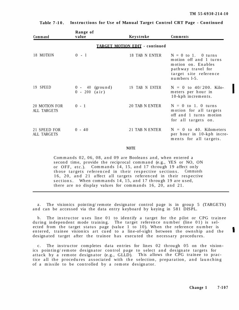
TM 55-6930-214-10
Table 7-10. Instructions for Use of Manual Target Control CRT Page - Continued
Range ofCommand value Keystroke Comments
TARGET MOTION EDIT - continued
18 MOTION 0 - l 18 TAB N ENTER
19 SPEED 0 - 40 (ground) 19 TAB N ENTER0 - 200 (a i r )
20 MOTION FOR 0 - 1 20 TAB N ENTERALL TARGETS
0 - 40 21 TAB N ENTER21 SPEED FORALL TARGETS
NOTE
N = 0 to 1. 0 turnsmotion off and 1 turnsmotion on. Enablespathway travel fortarget site referencenumbers l-5.
N = 0 to 40/200. Kilo-meters per hour in10-kph increments.
N = 0 to 1. 0 turnsmotion for all targetsoff and 1 turns motionfor all targets on.
N = 0 to 40. Kilometersper hour in 10-kph incre-ments for all targets.
Commands 02, 06, 08, and 09 are Booleans and, when entered asecond time, provide the reciprocal command (e.g., YES or NO, ONor OFF, etc.). Commands 14, 15, and 17 through 19 affect onlythose targets referenced in their respective sections. Commands16, 20, and 21 affect all targets referenced in their respectivesections. When commands 14, 15, and 17 through 19 are used,there are no display values for commands 16, 20, and 21.
a. The visionics pointing/remote designator control page is in group 5 (TARGETS)and can be accessed via the data entry keyboard by keying in 581 DISPL.
b. The instructor uses line 01 to identify a target for the pilot or CPG traineeduring independent mode training. The target reference number (line 01) is sel-ected from the target status page (value 1 to 10). When the reference number isentered, trainee visionics art cued to a line-of-sight between the ownship and thedesignated target after the trainee has executed the necessary procedures.
c. The instructor completes data entries for lines 02 through 05 on the vision-ics pointing/remote designator control page to select and designate targets forattack by a remote designator (e.g., GLLD). This allows the CPG trainee to prac-tice all the procedures associated with the selection, preparation, and launchingof a missile to be controlled by a remote designator.
Change 1 7-107
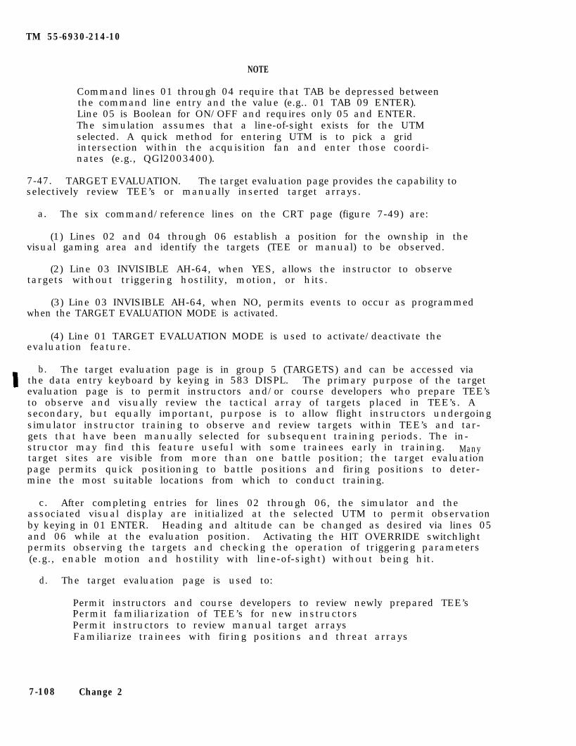
TM 55-6930-214-10
NOTE
Command lines 01 through 04 require that TAB be depressed betweenthe command line entry and the value (e.g.. 01 TAB 09 ENTER).Line 05 is Boolean for ON/OFF and requires only 05 and ENTER.The simulation assumes that a line-of-sight exists for the UTMselected. A quick method for entering UTM is to pick a gridintersection within the acquisition fan and enter those coordi-nates (e.g., QGl2003400).
7-47. TARGET EVALUATION. The target evaluation page provides the capability toselectively review TEE’s or manually inserted target arrays.
a. The six command/reference lines on the CRT page (figure 7-49) are:
(1) Lines 02 and 04 through 06 establish a position for the ownship in thevisual gaming area and identify the targets (TEE or manual) to be observed.
(2) Line 03 INVISIBLE AH-64, when YES, allows the instructor to observetargets without triggering hostility, motion, or hits.
(3) Line 03 INVISIBLE AH-64, when NO, permits events to occur as programmedwhen the TARGET EVALUATION MODE is activated.
(4) Line 01 TARGET EVALUATION MODE is used to activate/deactivate theevaluation feature.
b. The target evaluation page is in group 5 (TARGETS) and can be accessed viathe data entry keyboard by keying in 583 DISPL. The primary purpose of the targetevaluation page is to permit instructors and/or course developers who prepare TEE’sto observe and visually review the tactical array of targets placed in TEE’s. Asecondary, but equally important, purpose is to allow flight instructors undergoingsimulator instructor training to observe and review targets within TEE’s and tar-gets that have been manually selected for subsequent training periods. The in-structor may find this feature useful with some trainees early in training. Manytarget sites are visible from more than one battle position; the target evaluationpage permits quick positioning to battle positions and firing positions to deter-mine the most suitable locations from which to conduct training.
c. After completing entries for lines 02 through 06, the simulator and theassociated visual display are initialized at the selected UTM to permit observationby keying in 01 ENTER. Heading and altitude can be changed as desired via lines 05and 06 while at the evaluation position. Activating the HIT OVERRIDE switchlightpermits observing the targets and checking the operation of triggering parameters(e.g., enable motion and hostility with line-of-sight) without being hit.
d. The target evaluation page is used to:
Permit instructors and course developers to review newly prepared TEE’sPermit familiarization of TEE’s for new instructorsPermit instructors to review manual target arraysFamiliarize trainees with firing positions and threat arrays
7-108 Change 2
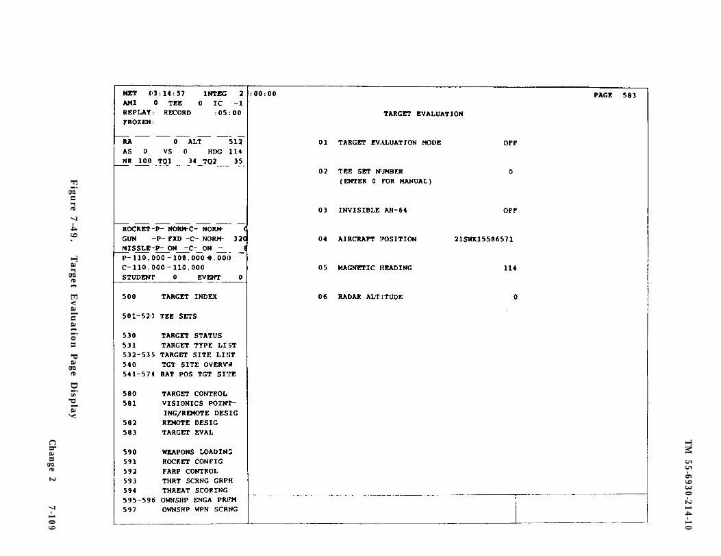
TM
55-6930-214-10
Figu
re 7-4
9.
Target E
valu
ation P
age Disp
lay
Ch
ange 2
7-109
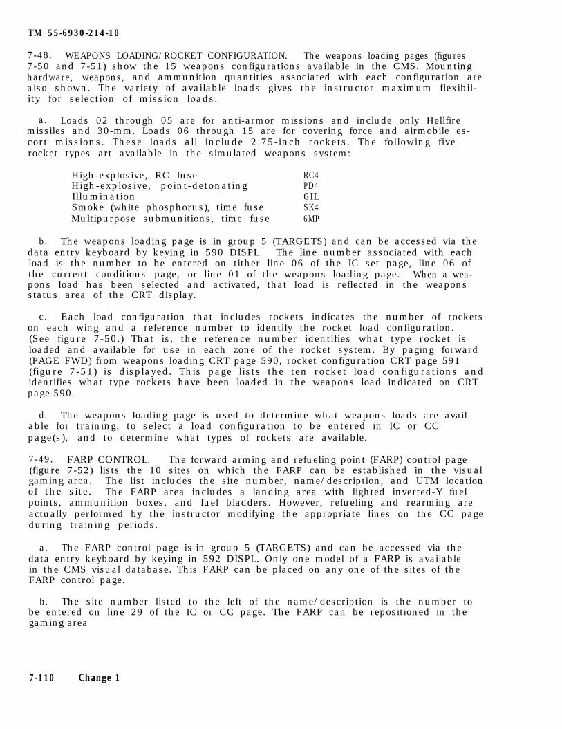
TM 55-6930-214-10
7-48. WEAPONS LOADING/ROCKET CONFIGURATION. The weapons loading pages (figures7-50 and 7-51) show the 15 weapons configurations available in the CMS. Mountinghardware, weapons, and ammunition quantities associated with each configuration arealso shown. The variety of available loads gives the instructor maximum flexibil-ity for selection of mission loads.
a. Loads 02 through 05 are for anti-armor missions and include only Hellfiremissiles and 30-mm. Loads 06 through 15 are for covering force and airmobile es-cort missions. These loads all include 2.75-inch rockets. The following fiverocket types art available in the simulated weapons system:
High-explosive, RC fuse RC4High-explosive, point-detonating PD4Illumination 6ILSmoke (white phosphorus), time fuse SK4Multipurpose submunitions, time fuse 6MP
b. The weapons loading page is in group 5 (TARGETS) and can be accessed via thedata entry keyboard by keying in 590 DISPL. The line number associated with eachload is the number to be entered on tither line 06 of the IC set page, line 06 ofthe current conditions page, or line 01 of the weapons loading page. When a wea-pons load has been selected and activated, that load is reflected in the weaponsstatus area of the CRT display.
c. Each load configuration that includes rockets indicates the number of rocketson each wing and a reference number to identify the rocket load configuration.(See figure 7-50.) That is, the reference number identifies what type rocket isloaded and available for use in each zone of the rocket system. By paging forward(PAGE FWD) from weapons loading CRT page 590, rocket configuration CRT page 591(figure 7-51) is displayed. This page lists the ten rocket load configurations andidentifies what type rockets have been loaded in the weapons load indicated on CRTpage 590.
d. The weapons loading page is used to determine what weapons loads are avail-able for training, to select a load configuration to be entered in IC or CCpage(s), and to determine what types of rockets are available.
7-49. FARP CONTROL. The forward arming and refueling point (FARP) control page(figure 7-52) lists the 10 sites on which the FARP can be established in the visualgaming area. The list includes the site number, name/description, and UTM locationof the site. The FARP area includes a landing area with lighted inverted-Y fuelpoints, ammunition boxes, and fuel bladders. However, refueling and rearming areactually performed by the instructor modifying the appropriate lines on the CC pageduring training periods.
a. The FARP control page is in group 5 (TARGETS) and can be accessed via thedata entry keyboard by keying in 592 DISPL. Only one model of a FARP is availablein the CMS visual database. This FARP can be placed on any one of the sites of theFARP control page.
b. The site number listed to the left of the name/description is the number tobe entered on line 29 of the IC or CC page. The FARP can be repositioned in thegaming area
7-110 Change 1
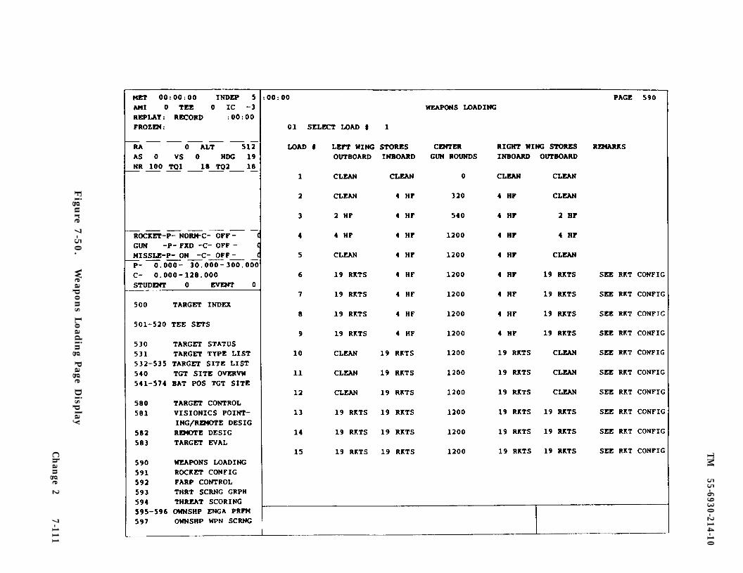
TM
55-6930-214-10
Figu
re 7-5
0.
Weap
ons L
oad
ing P
age Disp
lay
Ch
ange 2
7-111
TM
55-6930-214-10
Figu
re 7-5
1.
Rock
et Con
figuratio
n P
age Disp
lay
7-112C
han
ge 2
TM
55-6930-214-10
Figu
re 7-5
2.
Forw
ard A
rmin
g and R
efuelin
g Poin
t (FA
RP) C
on
trol P
age Disp
lay
Ch
ange 2
7-113
TM 55-6930-214-10
at any time by the instructor (e.g., while the CC CRT page is displayed, keying in29 TAB 01 ENTER causes the FARP to be located at FARP site 01).
c. The FARP control page can also be used to position and or reposition the FARPduring training periods.
7-50. ENGAGEMENT PERFORMANCE. The engagement performance pages 595A through F and596A through F (figure 7-53) summarize the twelve most recent target engagements bytither trainee with any of the aircraft weapons systems. An engagement consists ofone missile launch, one burst of cannon fire, or all rockets released in onetrigger pull.
a. The engagement performance page provides the instructor with feedback onpilot and CPG trainee performance during target engagements. (Table 7-11 lists andexplains the data elements that art recorded automatically and summarized on theCRT page during all engagements.)
b. The engagement performance page is in group 5 (TARGETS) and can be accessedvia the data entry keyboard by keying in 595 DISPL or 596 DISPL. The datapresented permits the instructor to analyze trainee performance using objectivedata that is not normally available during conventional weapons systems training.The engagement performance information on CRT pages 595 and 596 can be preservedfor future reference by using the hardcopy feature.
c. The engagement performance page is used by the instructor to analyze traineeperformance when engaging threat targets; to provide the instructor with feedbackrelated to trainee performance; and to debrief/critique trainees after the trainingperiod.
7-51. THREAT SCORING. The threat scoring page (figure 7-54) summarizes the threatduring the four most recent target engagements by either trainee with any of theaircraft weapons systems. An engagement consists of one missile launch, one burstof cannon fire, or all rockets released in one trigger pull. Threat scoring pages594A, 594B, and 594C summarize four target engagements each for a total of 12engagements or events. Since the three pages art identical in content, only one isillustrated.
a. The threat scoring pages provide the instructor with feedback on the threatto the aircraft during target engagements. (Table 7-12 lists and explains the dataelements that art recorded automatically and summarized on the CRT page during allengagements.)
b. The threat scoring pages are in group 5 (TARGETS) and can be accessed via thedata entry keyboard by keying in 594 DISPL. Use page-forward to review pages 594B,594C, or 594D. The data presented permits the instructor to analyze traineeperformance using objective data that is not normally available during conventionalweapons systems training. The threat scoring information on CRT page 594 can bepreserved for future reference by using the hardcopy feature.
c. The threat scoring pages art used by the instructor to analyze traineeperformance when engaging threat targets; to provide the instructor with feedbackrelated to trainee performance and threat to the aircraft; and to debrief/critiquetrainees after the training period.
7-114 Change 2
TM
55-6930-214-10
Figu
re 7-5
3.
Ow
nsh
ip E
ngagem
ent P
erform
ance P
age Disp
lay (S
heet 1
)
Ch
ange 2
7-1
14.1
/(7
-114.2
blan
k)

TM
55-6930-214-10
Figu
re 7-5
3.
Ow
nsh
ip E
ngagem
ent P
erform
ance P
age Disp
lay (S
heet 2
)
Ch
ange 2
7-115
TM
55-6930-214-10
Figu
re 7-5
4.
Th
reat Sco
ring P
age Disp
lay
7-116C
han
ge 2
TM 55-6930-214-10
Table 7-11. Engagement Performance Page Data Display
Item Data
Guns and Rockets
ENGAGEMENT NUMBER Number given to the engagement (1-999), only the12 most recent are displayed.
CREWMEMBER Crew member delivering the weapon, PLT or CPG.
WEAPONS TYPE Rockets or 30mm gun.
WEAPON MODE Mode in which weapon was released: GUN-NORM,FIXED; ROCKET-NORM, GROUND STOW, FLIGHT STOW,COOPERATIVE, IMPROPER COOP.
TARGET SITE No. between 1 and 99 from target sites list CRTpages 532 through 535.
TARGET TYPE No. 1-48 from target type list CRT pages 531A-C.
TARGET RANGE Distance from ownship to target in meters at timeof weapon release.
LOS/DESIGNATION SOURCE Aiming or designation method used. ResultsInclude the following: TADS, CPG IHADSS, PLTIHADSS, Remote, Autonomous, both, none.
ROUNDS FIRED
DISPOSITION
MISS DISTANCE BEST:LEFT/RIGHT, SHORT/LONG,LOW/HIGH
MISS DISTANCE WORST:LEFT/RIGHT, SHORT/LONGLOW/HIGH
MISS DISTANCE AVERAGE:LEFT/RIGHT, SHORT/LONG,LOW/HIGH
MISS DIST COMPONENT RNG:LEFT/RIGHT, SHORT/LONG,LOW/HIGH
STANDARD DEVIATION:LEFT/RIGHT, SHORT/LONG,LOW/HIGH
Total rounds fired at target during a singleengagement.
HIT or MISS or KILL
The resultant distance, in meters, at which theclosest impact point occurs, broken down into it’sindividual dimensions.
The resultant distance, in meters, at which thefurthest impact point occurs, broken down intoit’s individual dimensions.
The average of all the resultant impact distancesbroken down Into it’s individual dimensions.
The miss distance range spread, in meters, of allthe impact points in the individual dimensions.
The standard deviation of miss distance rangespreads in the individual dimensions.
Change 2 7-116.1
TM 55-6930-214-10
Table 7-11. Engagement Performance Page Data Display - Continued
Item Data
SIGHTING ERRORS:AZIMUTH, ELEVATION
ENGAGEMENT NUMBER
LOS START TIME
WEAPONS FIRE TIME
TOTAL EVENT TIME
CREW MEMBER
WEAPON MODE
TARGET SITE
TARGET TYPE
TARGET STATUS
TARGET RANGE
LOS/DESIGNATION SOURCE
PITCH RATE
YAW RATE
TOF
Guns and Rockets - continued
The deviation between the azimuth and elevationof the sighting path and the ownship to targetLOS vector.
Missiles
Number given to the engagement (l-999) only the12 most recent are displayed.
Time, hr:min:sec, at which LOS was first obtainedbetween the target and ownship.
Time, hr:min:sec, at which the weapon was fired.
Total time, In hr:min:sec, recorded from start ofLOS to weapon fire time.
PLT or CPG
Mode in which missile was released: LOBL,LOAL-DIR, LOAL-LO, LOAL-HI, with either NORM,RIPL or HAN.
No. between 1 and 99 from target sites list CRTpages 532 through 535.
No. 1-48 from target type list CRT pages 531A-C
Disposition of target at weapon fire time withrespect to LOS, Hostility, Motion, Destroyedstatus (L,H,M, and K respectively).
Slant range from ownship to target, in meters, atweapon fire time.
Source of designation laser, either ownship orremote designator.
Rate of change, in deg/sec, of ownship pitch atweapon fire time.
Rate of change, in deg/sec, of ownship yaw atweapon fire time.
Weapon Time of Flight measured from weapons firetime to impact of missile.
7-116.2 Change 2
TM 55-6930-214-10
Table 7-11. Engagement Performance Page Data Display - Continued
Item Data
DISPOSITION
MISS DISTANCE BEST:LEFT/RIGHT, SHORT/LONG
DES ON/OFF TARGET TIME
DES DELAY TIME
IMPROPER OFFSET TIME
SEEKER ON/OFF TARGET TIME
LAUNCH/REMOTE DES ANGLE
VISIBILITY
DES/SEEKER OBSCURED:CLOUDS, SMOKE/DUST
MASK INTERCEPTION: HORZ/VERT
DES CONSISTENCY/MODE
MISSILE SEEKER CODE
LRF/D Code
REMOTE CODE
*Indicates item is a “tolerance” item. When the value of these fields exceedsallowable limits an asterisk (*) is placed next to the field on the CRT page.
Missiles - continued
Hit or Miss
The resultant distance, in meters, at which theclosest impact point occurs, broken down Intoit’s individual dimensions.
The amount of time the ownship laser was on oroff the target.
Time delay between missile launch and the ownshiplasing the target.*
Amount or time (in critical window) that theownship was not lasing on the target.*
The time the seeker sees the target, based on theseeker tracking the designation laser spot andthe spot is on the target.*
Launch : Angle between seeker (on Rail) andtarget at weapon fire time.* Remote : Splashangle of remote designator on the target.*
Entered visibility at missile fire time.*
The time, in seconds, that the designator and/orseeker were obscured from the target by one ormore of the obscuration items listed during theentire flight of the missile.*
Record of seeker intersection with mask at anytime during the missile flight.*
Standard deviation of the designation pointvariances during the Critical Illumination Period(CIP) of the missile flight.*
Seeker code to assigned to missile fired incurrent engagement.*
Code assigned to ownship’s laser designatorduring the current engagement.*
Code assigned to remote designator during currentengagement.*
Change 2 7-117
TM 55-6930-214-10
Table 7-12. Threat Scoring Page Data Display
Item Data
EVENT NUMBER Defines which particular event that has oc-curred; as each event occurs, events scrollright with latest event displayed in left-lost column of CRT page 594A
TARGET TYPE Target that caused the end of an event(there are 16 target types)
TARGET SITE NUMBER Target site that was being used during eventrecorded (site number range is 0 - 99)
EVENT START TIME Specific time that event started; this isassociated with MET
EVENT END TIME Specific time that event ended; this is as-sociated with MET
EVENT EXPOSURE TIME Length of time that event lasted; this is thedifference between event start and end times
7-118 Change 2
TM 55-6930-214-10
Table 7-12. Threat Scoring Page Data Display - Continued
Item Data
TOTAL EXPOSURE TIME Length of time that target was in line-of-sight of ownship; time is accumulated overeach event until ownship breaks line-of-sight for greater than 5 seconds, in whichcase total exposure time is reset to 0
EXPOSURE ZONE (MAX)
EXPOSURE ZONE (MEAN)
EXPOSURE ZONE (FINAL)
FINAL RANGE (M)
VISIBILITY (M)
BACKDROP UTILIZATION
ASE UTILIZATION
PA (MAX)
PA (MEAN)
PA (FINAL)
PH (MAX)
PH (MEAN)
Maximum unmasked area that ownship was induring event (value range is 0 - 5)
Average unmasked area that ownship was induring event (value range is 0 - 5)
Last unmasked area that ownship was in attime event ended (value range is 0 - 5)
Distance in meters between target and own-ship at time event ended
Maximum distance in meters that ownship canvisually obtain an object
Percentage of backdrop that was used over aparticular time during event (value range is0 - 100)
Defines aircraft servicability equipment thatwas used effectively against a threat duringevent (parameters used are RDR,IR,and CF)
Maximum probability of being acquired thatownship obtained during event (value rangeis 0.00 - 1.00)
Average probability of being acquired thatownship obtained during event (value rangeis 0.00 - 1.00)
Final probability of being acquired thatownship obtained at time event ended (valuerange is 0.00 - 1.00)
Maximum probability of being hit that own-ship obtained during event (value range is0.00 - 1.00)
Average probability of being hit that own-ship obtained during event (value range is0.00 - 1.00)
7-119
TM 55-6930-214-10
Table 7-12. Threat Scoring Page Data Display - Continued
Item Data
PH (FINAL) Final probability of being hit that ownshipobtained at time event ended (value range is0.00 - 1.00)
DISPOSITION
HIT OVRD
HOSTILITY
ROUNDS REMAINING
OWNSHIP ENGAGEMENTS
CUM OWNSHIP ENGAGEMENTS
Result that occurred at end of event (param-eters used are HIT, MISS, and blank)
Defines whether or not a malfunction will beexecuted when ownship takes ahit from athreat (parameter is ON or OFF)
Defines whether or not a target is a threatto the ownship during event (parameters areON or OFF)
Number of rounds that threat has left attime event ended
Number of times that ownship fired a weaponat any target during event: number is tal-lied against all targets fired upon regard-less of which target caused end of event
Total number of times that ownship fired aweapon at any target, accumulated over allevents
TARGETS DESTROYED Number of targets destroyed during event
CUM TGTS DESTROYED Total number of targets destroyed, accumu-lated over all events
7-52. AUTOMATIC MALFUNCTION INSERTION. Automatic malfunction insertion (AMI)(figure 7-55) automatically inserts malfunctions or systems failures of simulatedaircraft components in response to preprogrammed conditions expected to occurduring an instructional activity. These contingent conditions/parameters include:
No. 1 engine rpm - %No. 2 engine rpm -- %Altitude - feet MSLAltitude - feet AGLIndicated airspeed - knotsWeapons release - seconds afterMission elapsed time - minutesPrevious malfunction occurrence
7-120
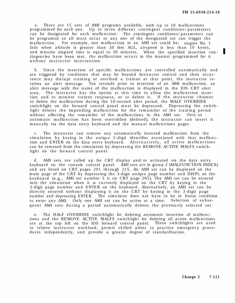
TM 55-6930-214-10
a. There are 15 sets of AMI programs available, with up to 10 malfunctionsprogrammed for each one. Up to three different contingent conditions/parameterscan be designated for each malfunction. The contingent conditions/parameters canbe programed so all must occur or any one of the designated set can trigger themalfunction. For example, one malfunction in an AMI set could be: engine No. 1fails when altitude is greater than 30 feet AGL, airspeed is less than 10 knots,and mission elapsed time is equal to 30 minutes. When the specified insertion con-tingencies have been met. the malfunction occurs in the manner programmed for itwithout instructor intervention.
b. Since the insertion of specific malfunctions are controlled automatically andare triggered by conditions that may be beyond Instructor control and their occur-rence may disrupt training or overload a trainee at that point, the instructor re-ceives an alert message. Ten seconds prior to insertion of an AMI malfunction. analert message with the name of the malfunction is displayed in the IOS CRT alertarea. The instructor has the option at this time to allow the malfunction inser-tion and to monitor trainee response, or to delete it. If the instructor choosesto delete the malfunction during the 10-second alert period, the MALF OVERRIDEswitchlight on the forward control panel must be depressed. Depressing the switch-light deletes the impending malfunction for the remainder of the training periodwithout affecting the remainder of the malfunctions in the AMI set. Once anautomatic malfunction has been overridden (deleted), the instructor can insert itmanually via the data entry keyboard and the manual malfunctions pages.
c. The instructor can remove any automatically inserted malfunction from thesimulation by keying in the unique 5-digit identifier associated with that malfunc-tion and ENTER on the data entry keyboard. Alternatively, all active malfunctionscan be removed from the simulation by depressing the REMOVE ACTIVE MALFS switch-light on the forward control panel.
d. AMI sets are called up for CRT display and/or activated via the data entrykeyboard on the console control panel. AMI sets are in group 2 (MALFUNCTION INDEX)and are listed on CRT pages 201 through 215. An AMI set can be displayed on themain page of the CRT by depressing the 3-digit unique page number and DISPL on thekeyboard (e.g., AMI set number 5 is on CRT page 205). The AMI set can be enteredinto the simulation when it is currently displayed on the CRT by keying in the3-digit page number and ENTER on the keyboard. Alternatively, an AMI set can bedirectly entered without displaying it on the CRT by keying in the 3-digit pagenumber and depressing ENTER. The simulator does not have to be in freeze conditionto enter any AMI. Only one AMI set can be active at a time. Selection of subse-quent AMI sets during a period automatically deletes the previously selected set.
e. The HALF OVERRIDE switchlight for deleting automatic insertion of malfunc-tions and the REMOVE ACTIVE MALFS switchlight for deleting all active malfunctionsare at the top left on the IOS forward control panel. These switchlights are usedto relieve instructor workload, permit skilled pilots to practice emergency proce-dures independently, and provide a greater degree of standardization.
Change 2 7-121
TM
55-6930-214-10
7-122
Figu
re 7-5
5.
Auto
matic M
alfunctio
n In
sertion P
age Disp
lay
Ch
ange 2
TM 55-6930-214-10
The AMI should not be used to introduce pilots to malfunctionsor in conjunction with other training activities for relativelyunskilled pilots. Manual insertion of malfunctions should beused for introduction. (Refer to MANUAL MALFUNCTIONS.) AMI’smay Increase the trainee task loading; as such, they should beused for advanced or continuation training activities and fortraining pilots in maintenance of skills.
7-53. MANUAL MALFUNCTION. Malfunction simulation (MS) enables the instructor tofail, partially or totally, a simulated aircraft component or to introduce an ab-normal aircraft condition. When such a failure is inserted into the simulation,the consequences duplicate the consequences of a corresponding failure in the air-craft. Actions taken by the trainee in the simulator following insertion of afailure have the same consequences as would be experienced under corresponding cir-cumstances in the aircraft. The instructor can insert or remove a simulated mal-function, but cannot change its programmed characteristic.
a. Malfunction simulation enables the instructor to simulate the occurrence ofcomponent malfunctions and failures so that the pilot and/or copilot/gunner can betrained to determine that an abnormal condition has occurred, identify the condi-tion, and take the prescribed corrective or compensating action. Since the simula-tor provides a safe environment in which such training can take place, it providesthe only environment in which training associated with the most hazardous malfunc-tions can take place. Approximately 336 malfunctions are available in the CMS.(Refer to tables 7-15 and 7-16, in Section IV of this chapter.)
b. Malfunctions are entered into the simulation through the data entry keyboardon the console control panel at each IOS. Categories of available malfunctions areindexed by system on CRT page 200 (figure 7-56). Individual malfunctions are codedwith a specific 5-digit identifier made up of the number of the CRT page on whichit appears (3 digits) and the line number (2 digits) on that CRT page. (See figure7-57.) Typing the 5-digit identifier and depressing ENTER on the keyboard insertsthe malfunction into the simulation (e.g., typing 22102 ENTER inserts the malfunc-tion appearing on line 02 of CRT page 221). Once inserted, the malfunction can beremoved by reentering its identifier. Up to 15 malfunctions can be active at anyone time, and up to six of these are displayed in the status area of the IOS CRTdisplay. Active malfunctions can also be removed from the simulation by depressingthe REMOVE ACTIVE MALFS switchlight on the forward control panel.
c. Instructors can use the malfunction simulation function to provide thetrainee with exposure to, and practice in dealing with, possible aircraft in-flightemergencies and aircraft systems malfunctions.
7-54. DEMONSTRATIONS. Demonstrations (DEMOS) consist of a prerecorded aircraftmaneuver or a series of aircraft maneuvers that provide a model for the desiredperformance of the maneuver being demonstrated. During demos, instruments, indi-cators, aircraft flight controls, motion system movements, visual display scenes,and associated aircraft sounds reflect an idealized performance of the maneuver asflown by an expert. Demos include audio briefings, explanations. and instructionalcommentary to facilitate trainees subsequent performance of the maneuver.
7-123
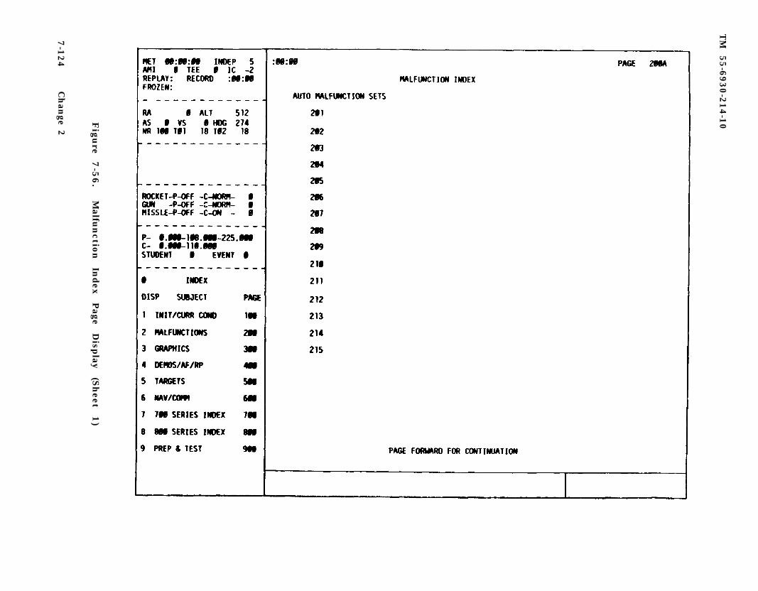
TM
55-6
930-2
14-1
0Fig
ure
7
-56
.M
alfun
ction
In
dex
Page
Disp
lay
(Sh
eet 1)
7-1
24
Ch
ange 2
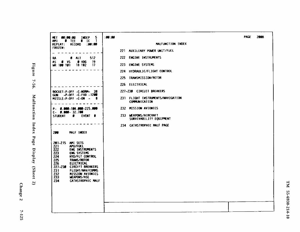
TM
55-6930-214-10
Fig
ure
7-56.M
alfun
ction
Ind
ex Pag
e Disp
lay (S
heet 2)C
han
ge 27-125
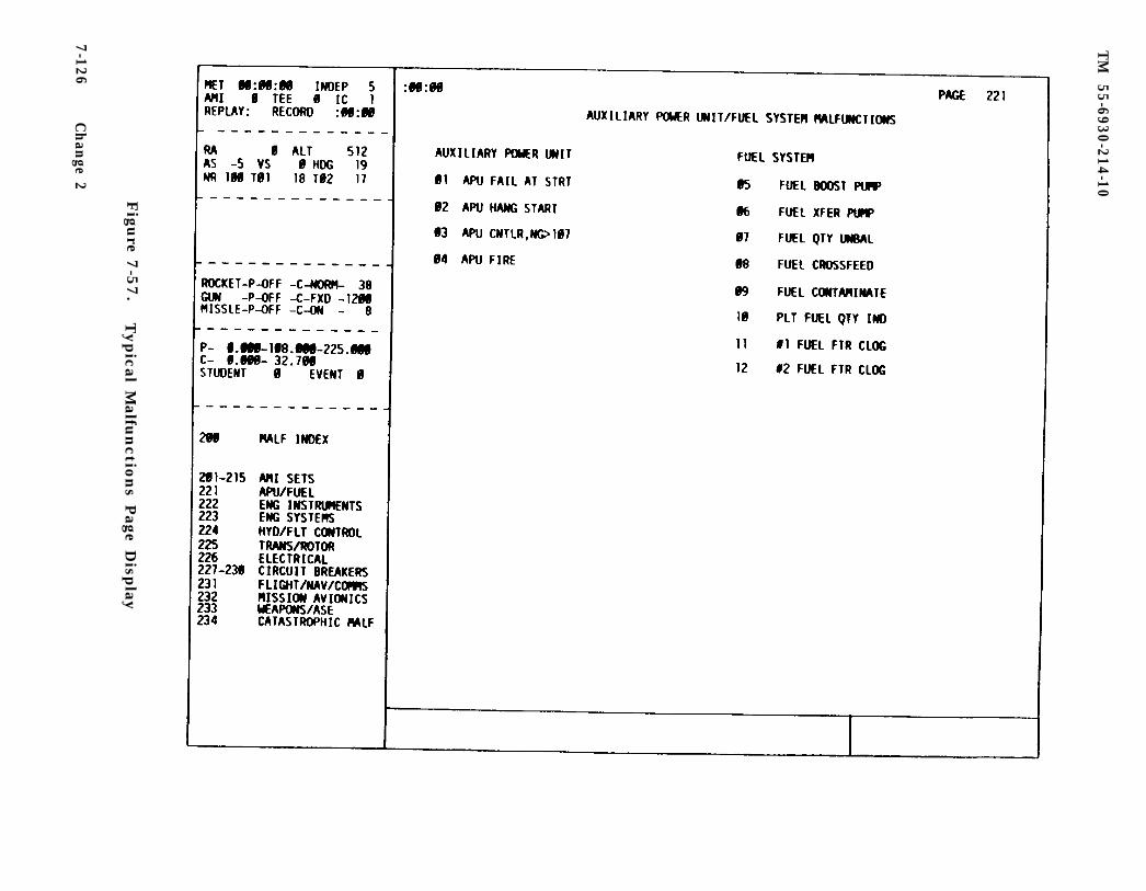
TM
55-6930-214-10
Figu
re 7-5
7.
Typical M
alfunctio
ns P
age Disp
lay
7-126C
han
ge 2
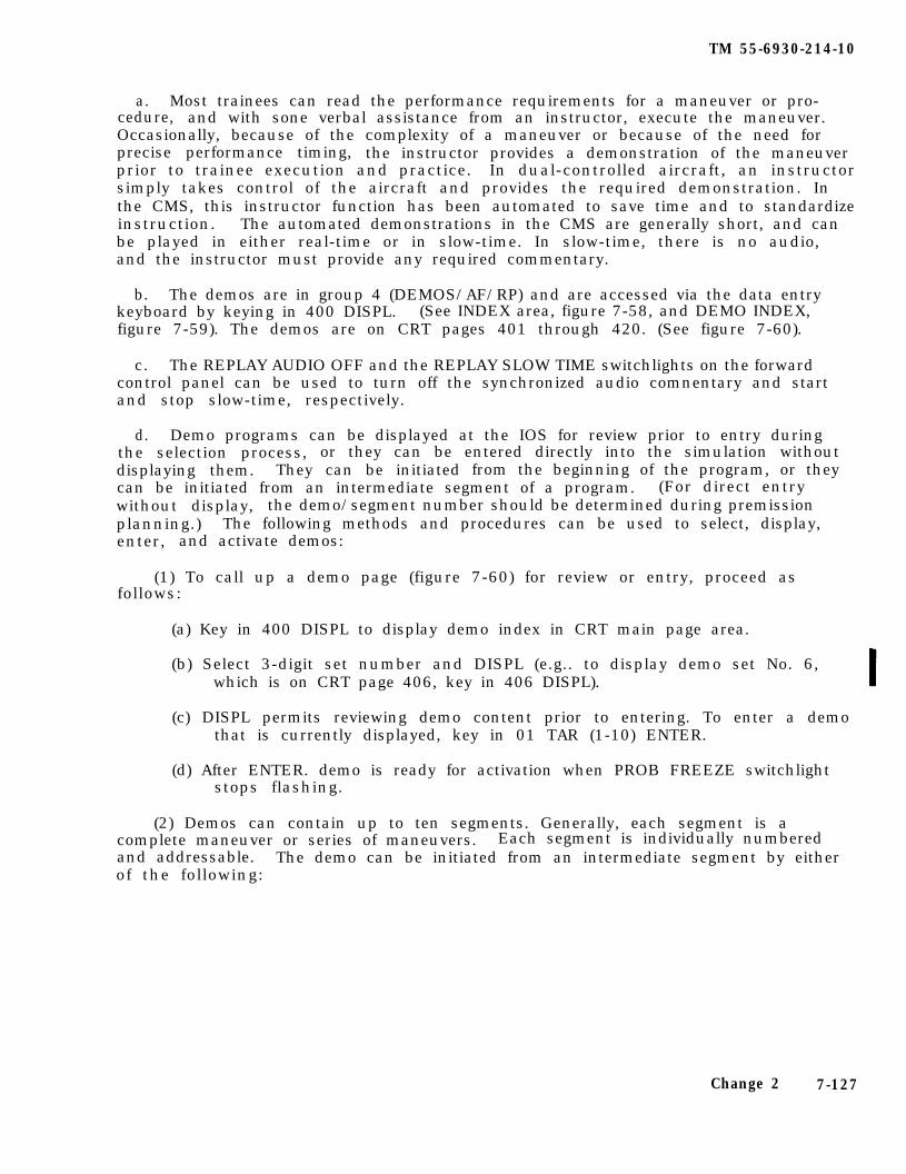
TM 55-6930-214-10
a. Most trainees can read the performance requirements for a maneuver or pro-cedure, and with sone verbal assistance from an instructor, execute the maneuver.Occasionally, because of the complexity of a maneuver or because of the need forprecise performance timing, the instructor provides a demonstration of the maneuverprior to trainee execution and practice. In dual-controlled aircraft, an instructorsimply takes control of the aircraft and provides the required demonstration. Inthe CMS, this instructor function has been automated to save time and to standardizeinstruction. The automated demonstrations in the CMS are generally short, and canbe played in either real-time or in slow-time. In slow-time, there is no audio,and the instructor must provide any required commentary.
b. The demos are in group 4 (DEMOS/AF/RP) and are accessed via the data entrykeyboard by keying in 400 DISPL. (See INDEX area, figure 7-58, and DEMO INDEX,figure 7-59). The demos are on CRT pages 401 through 420. (See figure 7-60).
c. The REPLAY AUDIO OFF and the REPLAY SLOW TIME switchlights on the forwardcontrol panel can be used to turn off the synchronized audio comnentary and startand stop slow-time, respectively.
d. Demo programs can be displayed at the IOS for review prior to entry duringthe selection process, or they can be entered directly into the simulation withoutdisplaying them. They can be initiated from the beginning of the program, or theycan be initiated from an intermediate segment of a program. (For direct entrywithout display, the demo/segment number should be determined during premissionplanning.) The following methods and procedures can be used to select, display,enter, and activate demos:
(1) To call up a demo page (figure 7-60) for review or entry, proceed asfollows:
(a) Key in 400 DISPL to display demo index in CRT main page area.
(b) Select 3-digit set number and DISPL (e.g.. to display demo set No. 6,which is on CRT page 406, key in 406 DISPL).
(c) DISPL permits reviewing demo content prior to entering. To enter a demothat is currently displayed, key in 01 TAR (1-10) ENTER.
(d) After ENTER. demo is ready for activation when PROB FREEZE switchlightstops flashing.
(2) Demos can contain up to ten segments. Generally, each segment is acomplete maneuver or series of maneuvers. Each segment is individually numberedand addressable. The demo can be initiated from an intermediate segment by eitherof the following:
Change 2 7-127
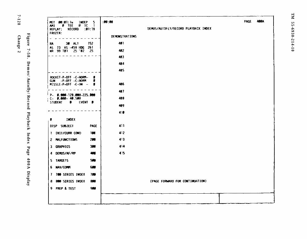
TM
55-6930-214-10
Figu
re 7-5
8. D
emos/A
uto
fly/R
ecord
Play
back In
dex P
age 400A
Disp
lay
7-128C
han
ge 2
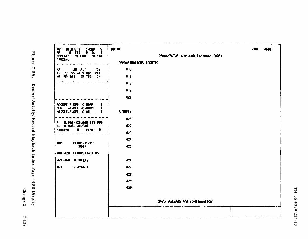
TM
55-6930-214-10
Figu
re 7-5
9.
Dem
os/A
uto
fly/R
ecord
Play
back In
dex P
age 400B
Disp
lay
Ch
ange 2
7-129
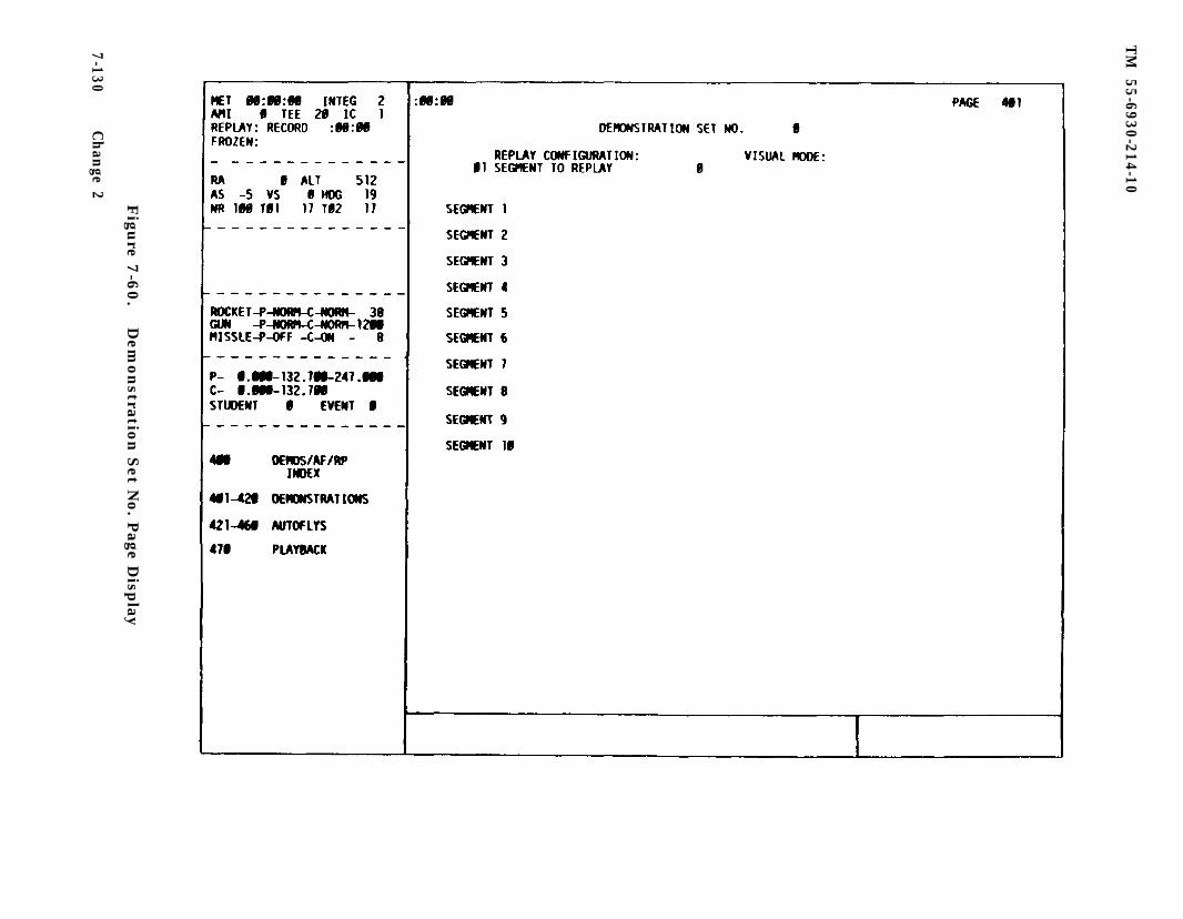
TM
55-6930-214-10
Figu
re 7-6
0.
Dem
on
stration
Set N
o. P
age Disp
lay
7-130C
han
ge 2
TM 55-6930-214-10
(a) With demo page displayed, select segment reference number and enter itvia data entry keyboard, using 01 TAB (segment 1-10) ENTER.
(b) If the page is not displayed, identify desired demo and its segmentnumber during premission planning. With simulator in freeze, activatedemo segment by keying in demo CRT page number. segment number, andENTER.
e. Maximum operating time for a demonstration is 5 minutes. At the conclusionof the demo, the simulator enters an automatic freeze. To continue training acti-v i t ies , the instructor can do one of the following:
(1) Enter required 3-digit number to reselect completed demo or any otherdemo, then enter 01 TAR (segment 1-10) ENTER.
(2) Enter required 3-digit number to select a new set of IC’s and, when PROBFREEZE switchlight stops flashing, continue training from that point.
f . Resume or flyout functions can be employed at any time during a demonstrationby activating PROB FREEZE, then selecting either the REPLAY RESUME or REPLAYFLYOUT switchlight.
(1) Depress REPLAY RESUME switchlight on forward control panel to continuetraining from the point at which demo was initiated (problem freeze condi-tion prior to start of demo). When PROB FREEZE switchlight stopsflashing, depress PROB FREEZE switchlight to permit training to continuefrom that point.
(2) Depress REPLAY FLYOUT switchlight on forward control panel to continuetraining from the point at which the demo terminates. Then, depress PROBFREEZE switchlight to permit training to continue from that point.
g. Demonstrations are used to:
(1) Supplement, or substitute for, a demonstration flown by the instructor.
(2) Provide an idealized, standardized model of maneuver performance in real-or slow-time.
(3) Present a standardized description of a maneuver or procedure, includingrelationships between relevant controls and indicators, the performance standardassociated with the maneuver or procedure, and other instructional information.
7-55. AUTOFLY. When the CPG cockpit is operated in the independent mode, there isin effect no pilot to fly the aircraft. To compensate for the missing pilot, auto-matic flight (AUTOFLY) flies the aircraft for the CPG. The autofly feature fliesthrough a prerecorded aircraft maneuver or series of contiguous maneuvers. When anautofly set is active. all CPG cockpit instrument and indicator activations, motionsystem movements, visual display scenes, and mechanical and aerodynamic soundsoccur. The CPG trainee has full access to and control over all sighting, sensor,and weapons systems normally available in that cockpit. At predetermined pointswithin the autofly set, usually firing positions, the instructor can interrupt theflight and assume manual control of the simulated aircraft heading and altitude.
Change 2 7-131
TM 55-6930-214-10
This allows the trainee additional time, if needed, to operate sighting, sensor,and weapon systems.
a. The autofly sets are in group 4 (DEMOS/AF/RP) and are accessed via the dataentry keyboard by keying in 400 DISPL and PAGE FWD to CRT page 400B or PAGE FWDagain to 400C to view the autofly index. The autofly sets are on CRT pages 421through 460. (See figures 7-59 and 7-61 through 7-63.)
b. Autofly programs can be displayed at the IOS for review prior to entry duringthe selection process, or they can be entered directly into the simulation withoutdisplaying them. They can be initiated from the beginning of the program, or theycan be initiated from an intermediate segment of a program. (For direct entrywithout display, the set/segment number should be determined during premissionplanning). The following methods and procedures can be used to select, display,enter, and activate autofly programs:
(1) To call up an autofly set page (figure 7-63) for review or entry, proceedas follows:
(a) Key in 400 DISPL and PAGE FWD to display autofly index in CRT main pagearea.
(b) Select 3-digit set number and DISPL. (e.g., to display autofly set N O.5, which is on CRT page 425, key in 425 DISPL). (Simulator must be infreeze to enter autofly programs.)
(c) DISPL permits reviewing autofly content prior to entering. To enter anautofly set that is currently displayed, key in 01 TAB (segment 1-10)ENTER.
(d) After ENTER, autofly is ready for activation when PROB FREEZE switch-light stops flashing.
(2) To activate an autofly set at an intermediate segment rather than thebeginning of the set, use either of the procedures below. In general, the inter-mediate segment is used to permit independent CPG gunnery training, permit indepen-dent CPG emergency systems training, and increase the line-of-sight exposure timeat selected locations. Proceed as follows:
(a) With autofly set displayed on main page area of CRT, select 2-digit linenumber adjacent to segment desired and enter it via the data entrykeyboard by entering 01 TAB (segment 1-10) ENTER.
7-132 Change 2
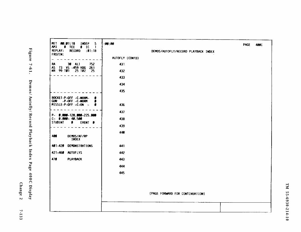
TM
55-6930-214-10
Figu
re 7-6
1.
Dem
os/A
uto
fly/R
ecord
Play
back In
dex P
age 400C
Disp
lay
Ch
ange 2
7-133

TM
55-6930-214-10
Figu
re 7-6
2.
Dem
os/A
uto
fly/R
ecord
Play
back In
dex P
age 400D
Disp
lay
7-134C
han
ge 2
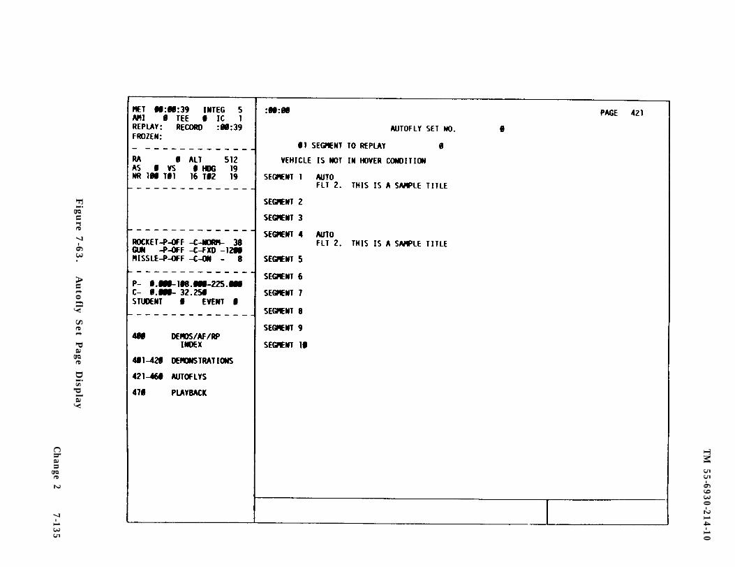
TM
55-6930-214-10
Figu
re 7-6
3.
Auto
fly S
et Page D
isplay
Ch
ange 2
7-135
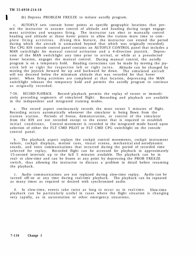
TM 55-6930-214-10
(b) Depress PROBLEM FREEZE to initiate autofly program.
c. AUTOFLY sets contain hover points at specific geographic locations that per-mit the instructor to assume control of altitude and heading during target engage-ment activities and weapons firing. The instructor can elect to manually controlheading and altitude at these hover points to allow the trainee more time to com-plete firing activities. (Using this feature, the instructor can extend the periodduring which the aircraft is unmasked beyond that which was originally recorded).The CPG IOS console control panel contains an AUTOFLY CONTROL panel that includes aMAN switchlight for manual control activation and a 4-direction joystick. Depres-sion of the MAN switchlight any time prior to arrival, or while at a preselectedhover location, engages the manual control. During manual control, the autoflyprogram is on a temporary hold. Heading corrections can be made by moving the joy-stick left or right for respective left or right turns. Altitude can be changed bymoving the joystick forward for up and backward for down. The simulated aircraftwill not descend below the minimum altitude that was recorded for that hoverpoint. When firing activities are completed at that location, depressing the MANswitchlight releases the temporary hold and permits the autofly program to continueas originally recorded.
7-56. RECORD/PLAYBACK. Record/playback permits the replay of recent or immedi-ately preceding segments of simulated flight. Recording and playback are availablein the independent and integrated training modes.
a. The record aspect continuously records the most recent 5 minutes of flight.Recording occurs automatically whenever the simulator is being flown from thetrainee station. Periods of freeze, demonstration, or control of the simulatorfrom the IOS are not recorded except to the extent that is required to establishinitial conditions. Control movement is recorded in the integrated mode based uponselection of either the FLT CMD PILOT or FLT CMD CPG switchlight on the consolecontrol panel.
b. The playback aspect replays the cockpit control movements, cockpit instrumentvalues, cockpit displays, motion cues, visual scenes, mechanical and aerodynamicsounds, and voice communications that occurred during the period of recorded timeselected for replay. Recorded flight can be accessed for playback in approximately15-second intervals up to the full 5 minutes available. The playback can be inreal- or slow-time and can be frozen at any point by depressing the PROB FREEZEswitch, thus allowing the instructor to discuss a problem in detail before resumingthe playback.
c. Audio communications are not replayed during slow-time replay. Audio can beturned off/on at any time during real-time playback. The playback can be repeatedas many times as required or desired with synchronized audio.
d. In slow-time, events take twice as long to occur as in real-time. Slow-timeplayback can be particularly useful in cases where the flight situation is changingvery rapidly, as in autorotation or other emergency situations.
7-136 Change 1
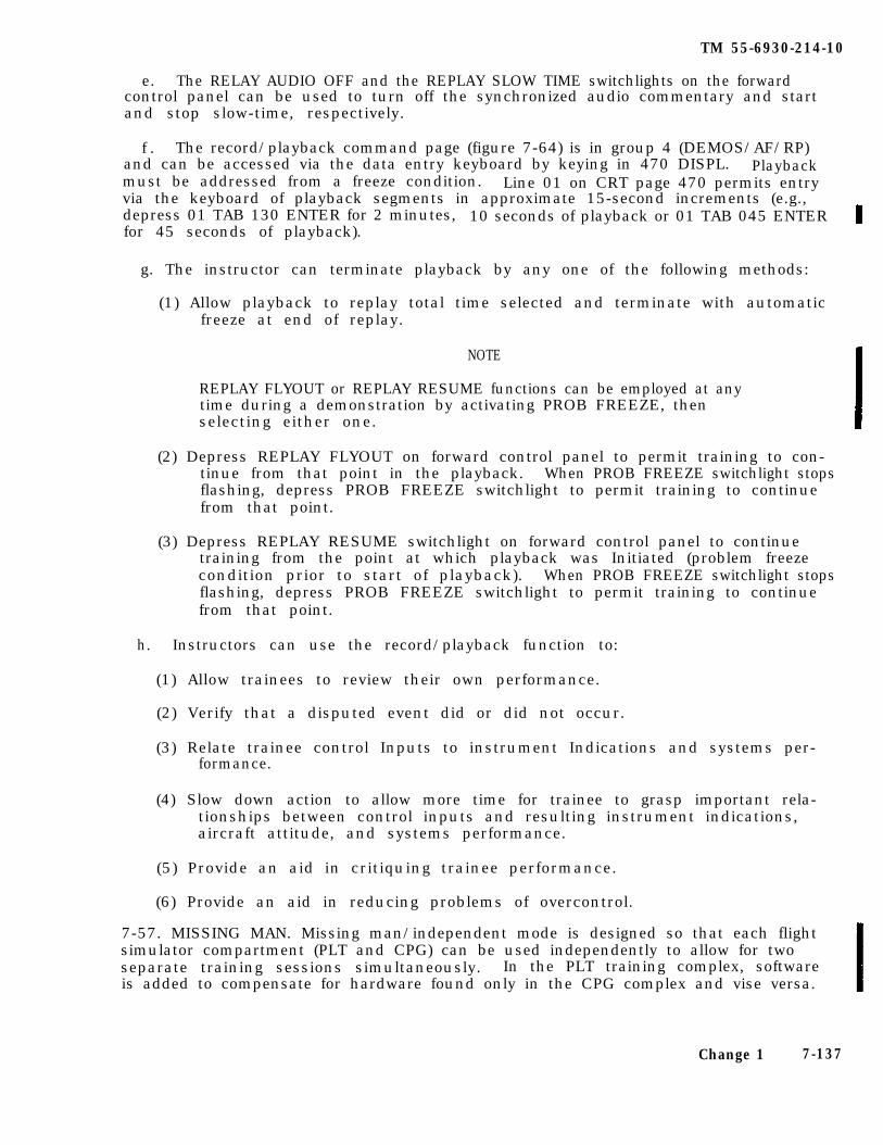
TM 55-6930-214-10
e. The RELAY AUDIO OFF and the REPLAY SLOW TIME switchlights on the forwardcontrol panel can be used to turn off the synchronized audio commentary and startand stop slow-time, respectively.
f . The record/playback command page (figure 7-64) is in group 4 (DEMOS/AF/RP)and can be accessed via the data entry keyboard by keying in 470 DISPL. Playbackmust be addressed from a freeze condition. Line 01 on CRT page 470 permits entryvia the keyboard of playback segments in approximate 15-second increments (e.g.,depress 01 TAB 130 ENTER for 2 minutes, 10 seconds of playback or 01 TAB 045 ENTERfor 45 seconds of playback).
g. The instructor can terminate playback by any one of the following methods:
(1) Allow playback to replay total time selected and terminate with automaticfreeze at end of replay.
NOTE
REPLAY FLYOUT or REPLAY RESUME functions can be employed at anytime during a demonstration by activating PROB FREEZE, thenselecting either one.
(2) Depress REPLAY FLYOUT on forward control panel to permit training to con-tinue from that point in the playback. When PROB FREEZE switchlight stopsflashing, depress PROB FREEZE switchlight to permit training to continuefrom that point.
(3) Depress REPLAY RESUME switchlight on forward control panel to continuetraining from the point at which playback was Initiated (problem freezecondition prior to start of playback). When PROB FREEZE switchlight stopsflashing, depress PROB FREEZE switchlight to permit training to continuefrom that point.
h. Instructors can use the record/playback function to:
(1) Allow trainees to review their own performance.
(2) Verify that a disputed event did or did not occur.
(3) Relate trainee control Inputs to instrument Indications and systems per-formance.
(4) Slow down action to allow more time for trainee to grasp important rela-tionships between control inputs and resulting instrument indications,aircraft attitude, and systems performance.
(5) Provide an aid in critiquing trainee performance.
(6) Provide an aid in reducing problems of overcontrol.
7-57. MISSING MAN. Missing man/independent mode is designed so that each flightsimulator compartment (PLT and CPG) can be used independently to allow for twoseparate training sessions simultaneously. In the PLT training complex, softwareis added to compensate for hardware found only in the CPG complex and vise versa.
Change 1 7-137
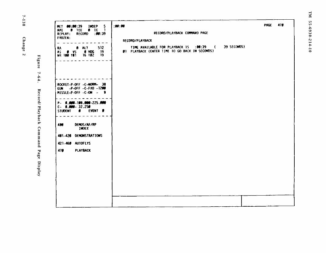
TM
55-6
930-2
14-1
0
Fig
ure
7
-64
.R
ecord
/Play
back
Com
man
d P
age Disp
lay
7-1
38
Ch
ange 2
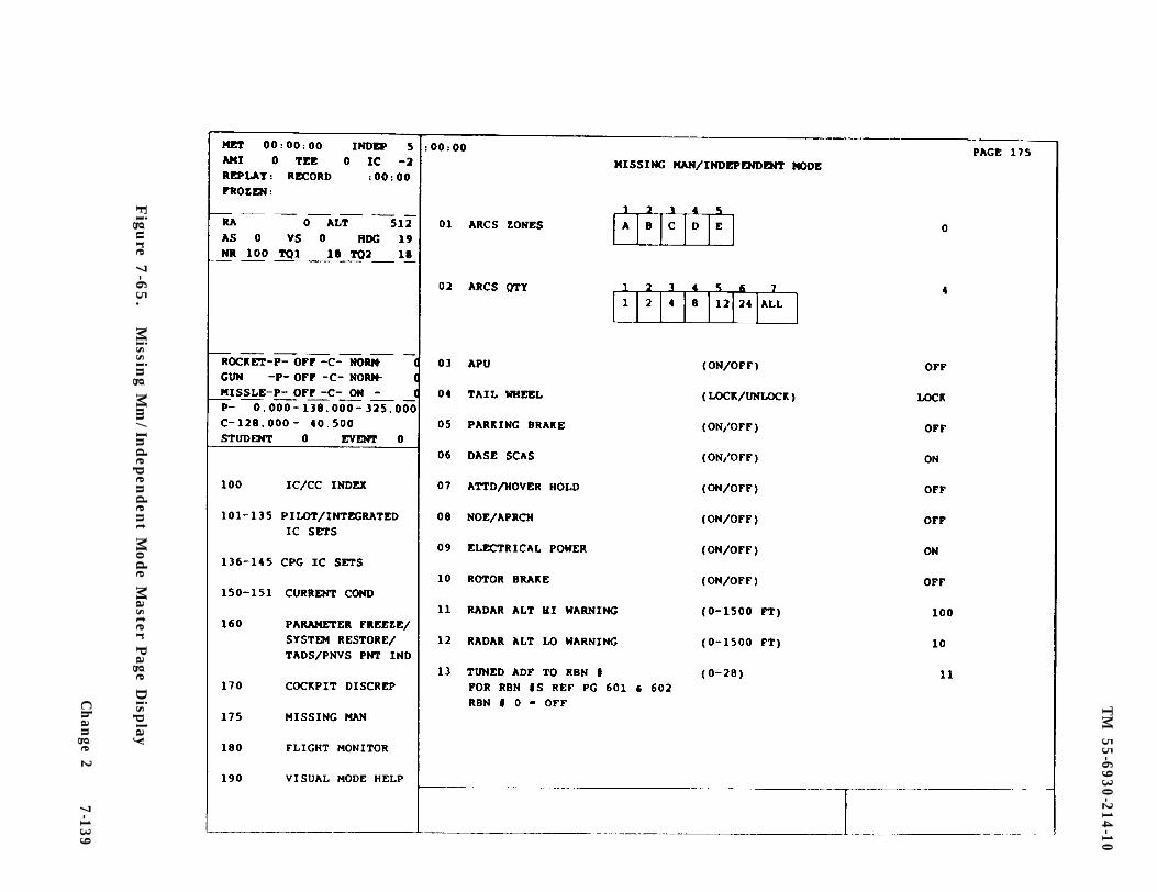
TM
55-6930-214-10
Figu
re 7-6
5.
Missin
g Mm
/Indep
enden
t Mode M
aster Page D
isplay
Ch
ange 2
7-139
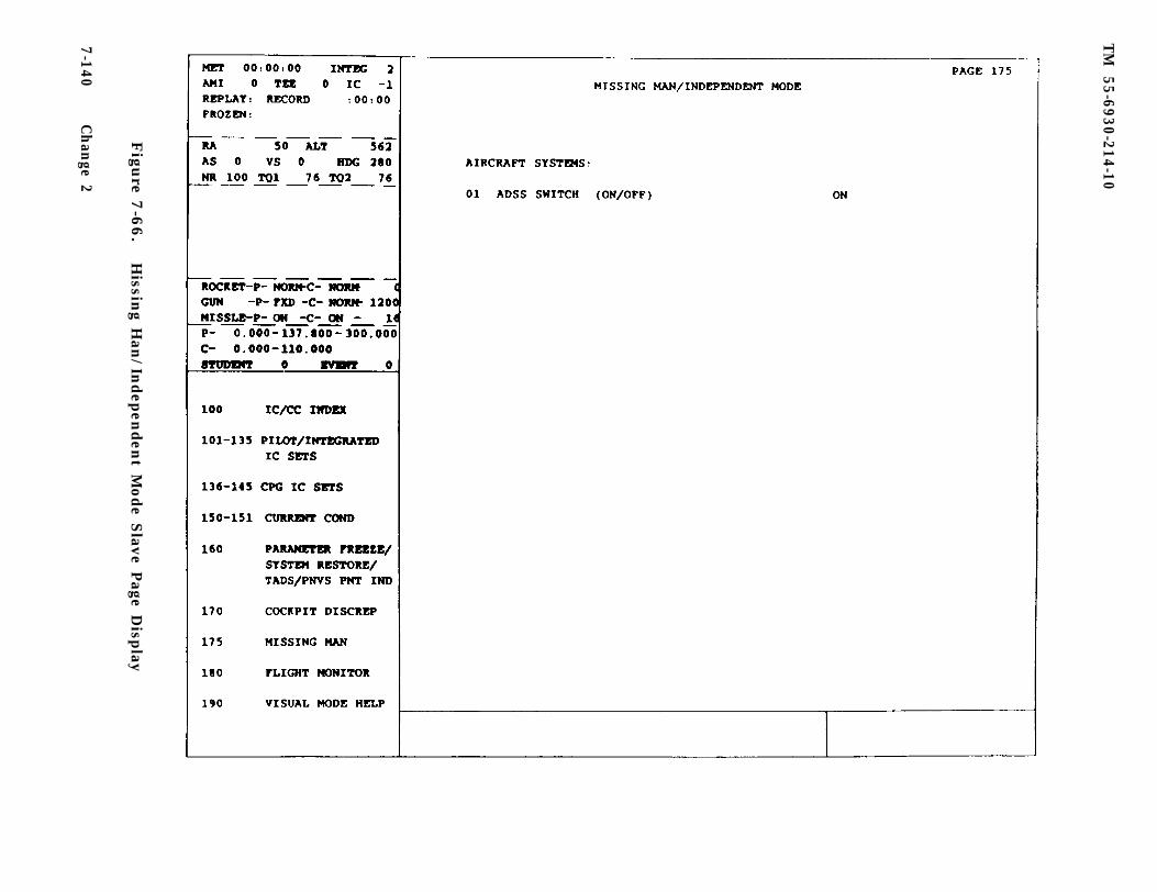
TM
55-6930-214-10
Figu
re 7-6
6.
Hissin
g Han
/Indep
enden
t Mode S
lave Page D
isplay
7-140C
han
ge 2
TM 55-6930-214-10
7-57.1 Visual moding in the independent mode allows for PNVS, TADS, and OTW dis-play generation. (Refer to table 5-l.) Since visual displays in the independentmode depend on only one DIG providing that display, changing visual modes in onecompartment affects the display on the other. This change is automatic to the com-partment not instituting the visual mode edit. The compartment not instituting thechange is placed in blinking freeze, and the visual mode changes on that compart-ment correspond to what is allowable for the edited mode.
7-57.2 The instructor has some control over missing man hardware in the indepen-dent mode by calling up missing man/Independent mode display CRT page 175.
a. The CPG IOS station missing man display (figure 7-65) provides the control-ling instructor with insertable control functions, each of which is provided with adefault value. The CPG IOS can use the missing man display to:
(1) Select which ARCS zone to load (line 01).
(2) Select quantity of rockets to be fired per trigger pull (line 02).
(3) Establish certain conditions by toggling lines 03 through 10 to turn theitem on or off or, in case of line 04, lock or unlock the tailwheel.
(4) The last three lines (11 through 13) provide a means of establishing radaraltitude high and low warnings and selecting one of 28 NDB ranges.
b. The master display is divided into three columns: the first identifies thefunction, the second identifies the range of the function, and the third lists thedefault or selected value.
c. The pilot IOS missing man display (figure 7-66) provides a means of turningon or off the air data sensor system (ADSS), which controls various aircraft sys-tems. In the normal (default) mode, the ADSS switch is ON.
7-57.3 Ability to edit FCC waypoints in the independent mode is available to bothinstructors by CRT current conditions page 151. UTM and altitude entries are onseparate lines for each waypoint. In addition, the instructions have the capabili-ty to select one of two training configurations at each trainer. The GUNNER/TARGETconfiguration provides training in weapons delivery skills and the CLEAN/THREATconfiguration develops threat recognition and avoidance skills. The appropriateconfiguration is selected from CRT page 150, line 62.
7-57.4 OWNSHIP WEAPONS SCORING. The ownship weapons scoring page (figure 7-66.1)is a map page provided to show the following features:
Target or Illumination round of interestSighting designation pathImpact locationsAngular constraint markings for missiles1, 2, and 3 km selectable scalesTarget centered on map at time of engagementWeapon type, disposition, and miss distance
a. The user can select any of the 12 defined engagements from the weapon scoringpages, as well as any of the three allowable map scales.
Change 2 7-140.1
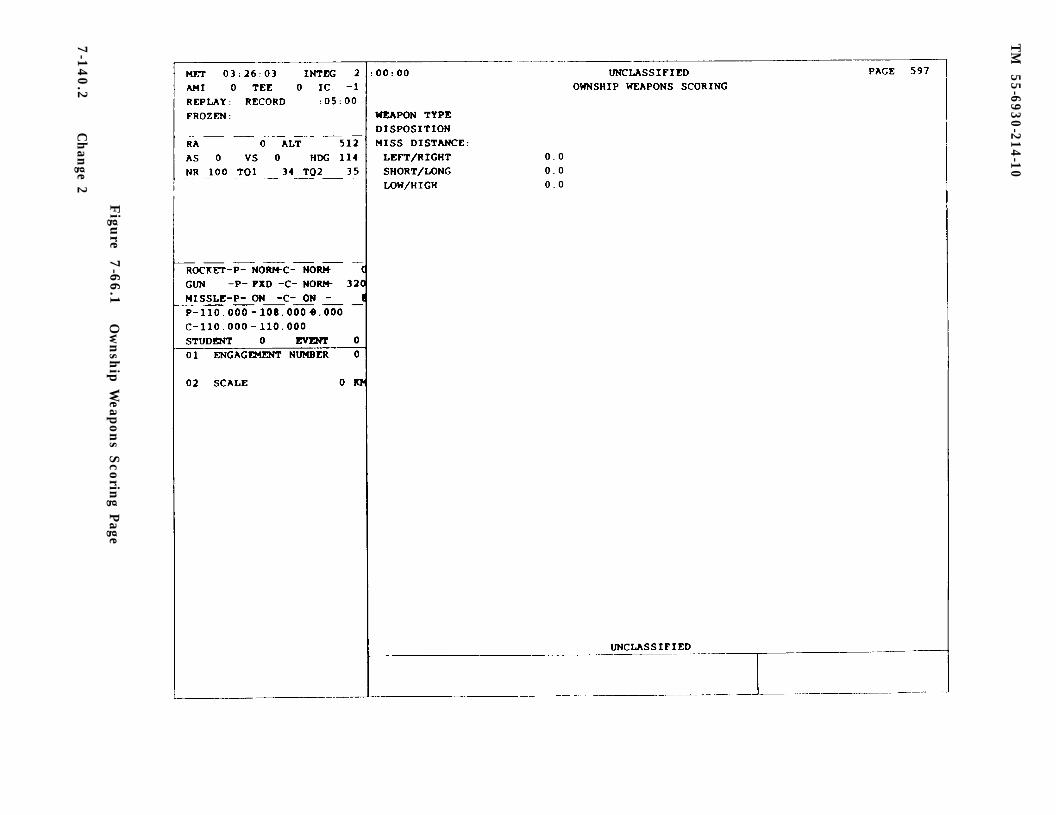
TM
55-6930-214-10
Figu
re 7-6
6.1
Ow
nsh
ip Weapon
s Scorin
g Page
7-1
40.2
Ch
ange 2
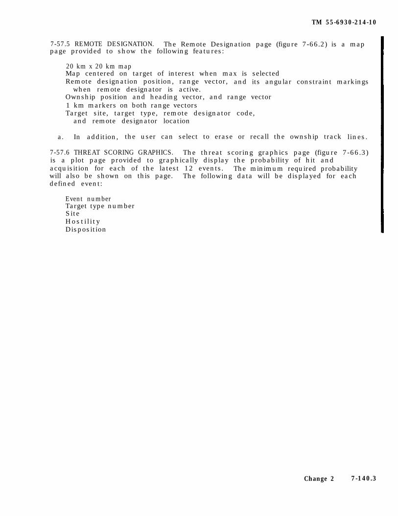
TM 55-6930-214-10
7-57.5 REMOTE DESIGNATION. The Remote Designation page (figure 7-66.2) is a mappage provided to show the following features:
20 km x 20 km mapMap centered on target of interest when max is selectedRemote designation position, range vector, and its angular constraint markings
when remote designator is active.Ownship position and heading vector, and range vector1 km markers on both range vectorsTarget site, target type, remote designator code,
and remote designator location
a. In addition, the user can select to erase or recall the ownship track lines.
7-57.6 THREAT SCORING GRAPHICS. The threat scoring graphics page (figure 7-66.3)is a plot page provided to graphically display the probability of hit andacquisition for each of the latest 12 events. The minimum required probabilitywill also be shown on this page. The following data will be displayed for eachdefined event:
Event numberTarget type numberSiteHosti l ityDisposition
Change 2 7-140.3
TM
55-6930-214-10
7-1
40.4
Ch
ange 2
Figu
re 7-6
6.2
Rem
ote D
esignatio
n P
age
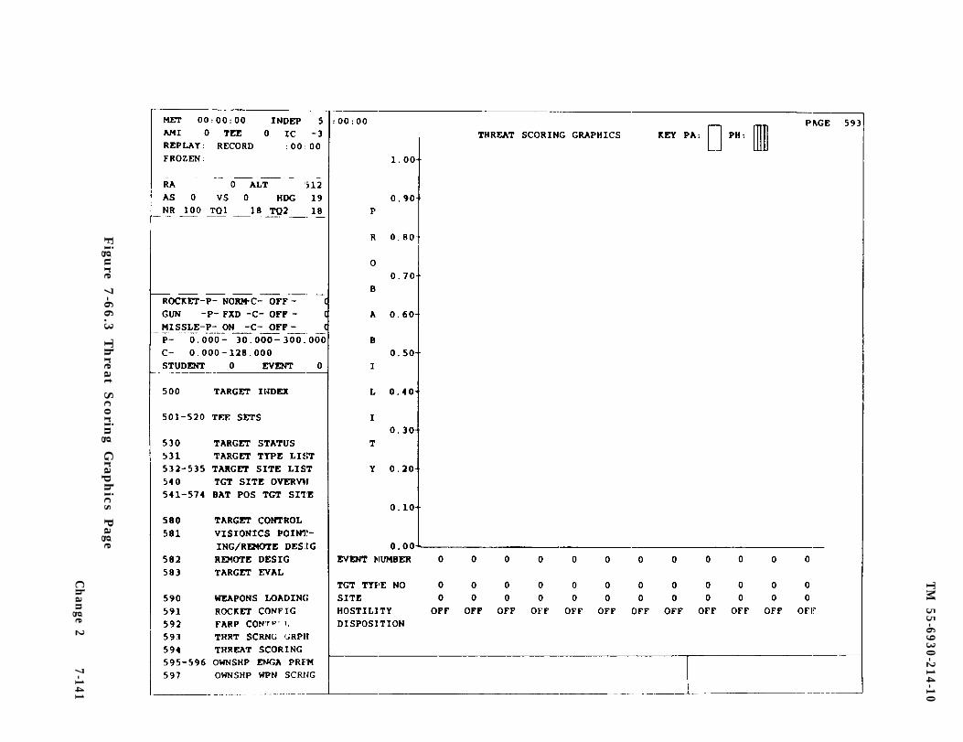
TM
55-6930-214-10
Figu
re 7-6
6.3
Th
reat Sco
ring G
raph
ics Page
Ch
ange 2
7-141
TM 55-6930-214-10
Section III. AUTOMATED PROGRAM PREPARATION
7-58. INSTRUCTIONAL FEATURE PREPARATION. Provisions have been incorporated intothe CMS that permit designated instructors to prepare the automated programs usedby all instructors during training. In the interest of maintaining quality controlof program content and standardizing training, only designated instructors areresponsible for developing and/or modifying automated exercises. The skills re-quired to make changes or to prepare new programs are those typically possessed bythe AH-64 CMS flight instructors. No special technical or programming skills arerequired.
There are four feature preparation programs in the CMS, located in group 9(PREPARATION). In order to call up the preparation programs from the IOS, the sys-tem must be enabled by a qualified operator in the computer room. Once the prepar-ation programs are enabled in the computer room, any of the four programs can becalled up via the data entry keyboard by keying in its 3-digit page number. Theprograms and their page numbers are:
Automatic malfunction insertion preparation (CRT page 920)Demonstration preparation (CRT page 940)Autofly preparation (CRT page 945)Target engagement exercise preparation (CRT page 950)
b. Specific planning must take place prior to the development of an AM, demo,autofly, or TEE to:
(1) Develop a scenario that clearly indicates what the training objectives ofthe program are.
(2) Ensure that each exercise or demonstration supports one or more trainingobjective(s) .
c. The following checklist has been prepared for use as a guide to enhance thedevelopment of automated exercises and demos:
(1) Objectives of the training period:
(a) Perform basic aircraft flight maneuvers.
(b) Perform tactical instrument flight.
(c) Perform NOE flight with/without PNVS/TADS.
(d) Perform NOE navigation with/without PNVS/TADS.
(e) Perform target-type engagements:
HardSoft
(f) Weapons to be employed:
MissilesRockets30-mm
7-142
TM 55-6930-214-10
(g) Type of weapons engagements:
AutonomousRemote - DesignationSingle-target engagementsMultitarget engagements
(h) Range to target engagement:
Long rangeMedium rangeShort range
(i) Perform emergency procedures/systems malfunction training:
1 Enroute to battle positions:
Instrument environmentVisual environmentPNVS/TADS environmentMission go-no-go decision required
2 At the battle position:
With/without active threatAircraft systems failuresHit induced malfunctions
3 Systems and crewmember:
PilotCPG
(2) Type of demo required to support training periods (remember, demos are ofshort duration and employment of them optimizes simulator training time):
Complex flight procedures (e.g., autorotations)Complex engagement procedures and/or techniquesEmergency procedures
(3) Supporting materials/simulator features required for the training period:
MapsOP-ordersIC setsFARPSTraining period worksheetsTEEAMIDEMO
7-143
TM 55-6930-214-10
d. After assembling all the required material and preparing the flight profilesor flight scenarios and descriptions of the tactical situation, an AMI, demo, auto-fly, or TEE worksheet should be prepared. After completing the appropriate work-sheet(s), the data is ready to be entered for the selected exercise or demo.Descriptions, instruction models, and worksheets for the preparation of each typeof automated program are provided in the following sections.
7-59. AMI PREPARATION. The purpose of the AMI preparation feature is to permitAMI exercises to be prepared by selecting a set of malfunctions to be simulatedduring a subsequent training period and the identifying contingencies, which, ifmet during that period, will trigger the insertion of each of the selected malfunc-tions. Up to three contingencies (parameters) may be required to activate theappropriate malfunction. There is computer space for preparation and storage of 15sets of AMI exercises in the CMS, while up to 10 malfunctions can be selected foreach AMI exercise.
a. In conjunction with the development of the scenarios, the IC set to be usedwith each scenario should be identified. This is important because using a speci-fied IC set with a particular AMI exercise provides an additional degree of stand-ardization for the planned malfunction instruction and places the simulatedaircraft in an initial position most likely to trigger the AMI.
b. When CRT page 920 is keyed in via the data entry keyboard, the main page areacontains a blank AMI set page (figure 7-67) that is filled in during the prepara-tion process and then stored in group 2 (MALFUNCTIONS, CRT pages 201 through 215)for recall during subsequent training periods. The data from the AMI worksheet(figure 7-68) should be entered on the appropriate lines on CRT page 920. Theindex and control area (figure 7-67) includes the AMI PREP IDENTIFIERS with refer-ence numbers (REF #) for the PARAMETERS, OPERATORS, and CORRECTORS that are re-quired for entry on the CRT page.
c. Line 01 AMI PREP (main page area, figure 7-67) is used to enter the identi-fying set number for the AMI set. When these sets are completed and stored, theyappear in the malfunctions index (CRT page 200). and each has a discrete pagenumber. CRT pages 201 through 215 correspond to AMI sets 1-15, respectively.
d. On CRT page 920, there are four lines of data for each malfunction. Thefirst line for each malfunction (lines 02, 06, 10, 14, 18, 22, 26, 30, 34, and 38)is used to key in the selected 5-digit malfunction numbers for the set being pre-pared. The indented line numbers (03, 04. 05; 07, 08, 09; etc.) are for insertionof the contingencies that will trigger the malfunction. Up to three contingenciescan be entered for each malfunction. Each contingency line accommodates one para-meter, one operator, and one connector, as required to define the triggeringactivity. (The contingencies are further explained in subparagraph f).
e. Command line 77 is used to clear the display and, when keyed in, clears alldata items entered. When an AMI prep is complete, keying command line 88 placesthe data displayed on CRT page 920 in permanent storage in the malfunction groupingwhere it is available for recall by its CRT page number (201 through 215). Commandline 99 is used to terminate (cancel) the preparation activity: nothing is retainedin storage when line 99 is keyed in.
7-144
TM
55-6930-214-10
Figu
re 7-6
7.
Auto
matic M
alfun
ction
Insertio
n P
rep P
age Disp
lay
Ch
ange 2
7-145
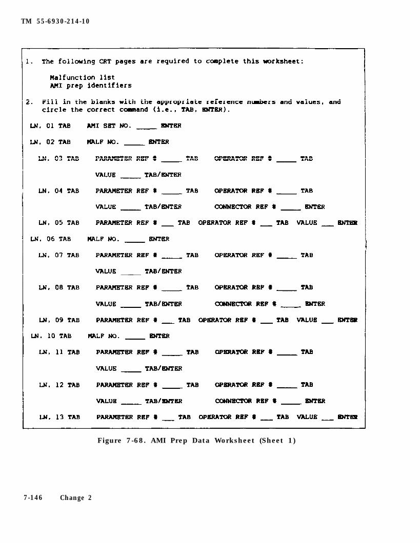
TM 55-6930-214-10
Figure 7-68. AMI Prep Data Worksheet (Sheet 1)
7-146 Change 2
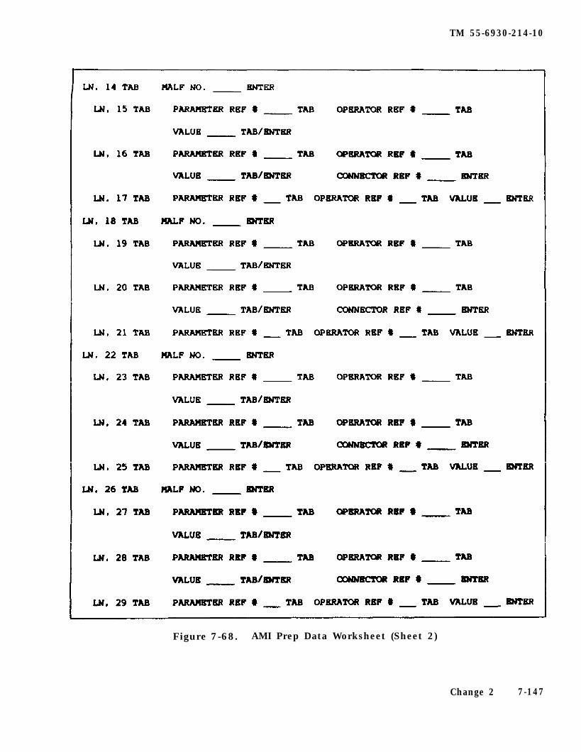
TM 55-6930-214-10
Figure 7-68. AMI Prep Data Worksheet (Sheet 2)
Change 2 7-147
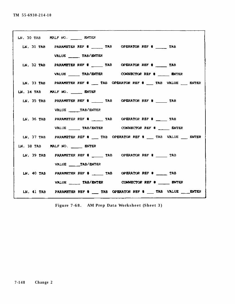
TM 55-6930-214-10
Figure 7-68. AM Prep Data Worksheet (Sheet 3)
7-148 Change 2
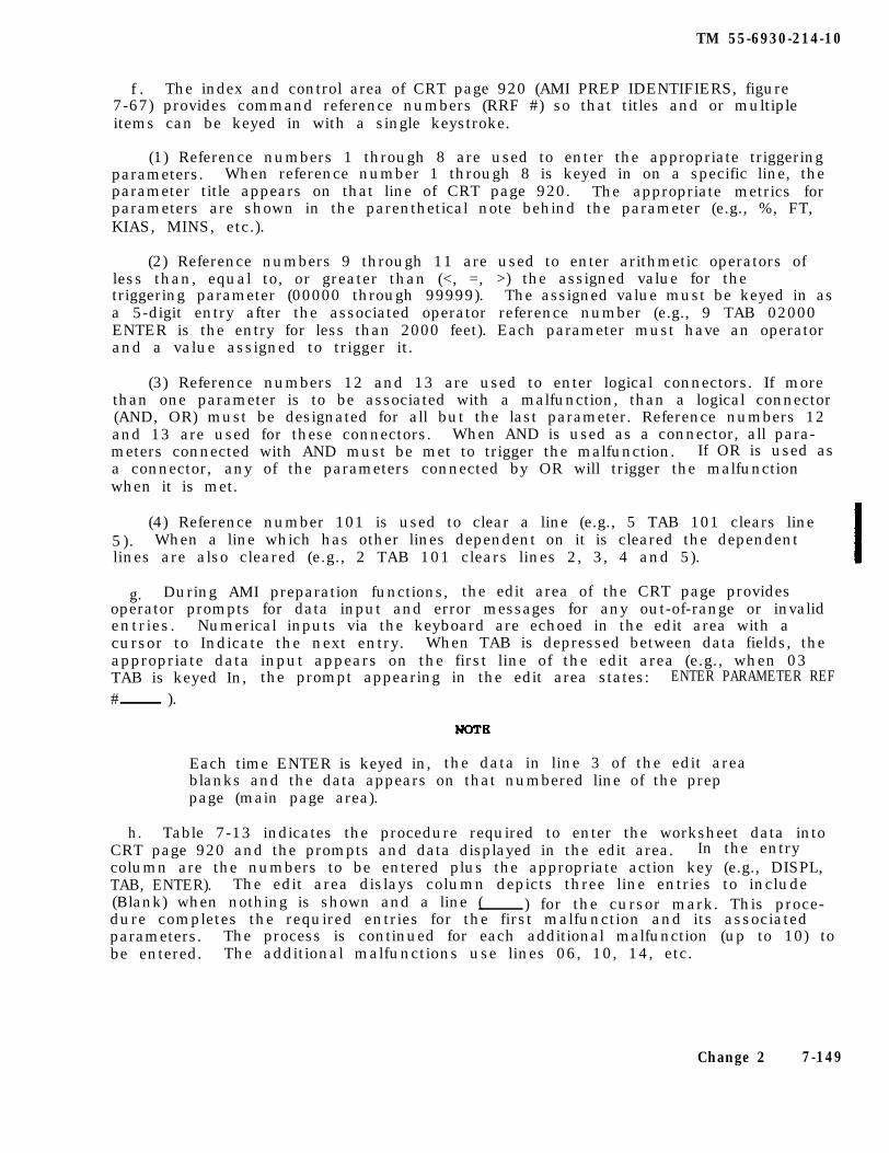
TM 55-6930-214-10
f . The index and control area of CRT page 920 (AMI PREP IDENTIFIERS, figure7-67) provides command reference numbers (RRF #) so that titles and or multipleitems can be keyed in with a single keystroke.
(1) Reference numbers 1 through 8 are used to enter the appropriate triggeringparameters. When reference number 1 through 8 is keyed in on a specific line, theparameter title appears on that line of CRT page 920. The appropriate metrics forparameters are shown in the parenthetical note behind the parameter (e.g., %, FT,KIAS, MINS, etc.).
(2) Reference numbers 9 through 11 are used to enter arithmetic operators ofless than, equal to, or greater than (<, =, >) the assigned value for thetriggering parameter (00000 through 99999). The assigned value must be keyed in asa 5-digit entry after the associated operator reference number (e.g., 9 TAB 02000ENTER is the entry for less than 2000 feet). Each parameter must have an operatorand a value assigned to trigger it.
(3) Reference numbers 12 and 13 are used to enter logical connectors. If morethan one parameter is to be associated with a malfunction, than a logical connector(AND, OR) must be designated for all but the last parameter. Reference numbers 12and 13 are used for these connectors. When AND is used as a connector, all para-meters connected with AND must be met to trigger the malfunction. If OR is used asa connector, any of the parameters connected by OR will trigger the malfunctionwhen it is met.
(4) Reference number 101 is used to clear a line (e.g., 5 TAB 101 clears line5). When a line which has other lines dependent on it is cleared the dependentlines are also cleared (e.g., 2 TAB 101 clears lines 2, 3, 4 and 5).
g. During AMI preparation functions, the edit area of the CRT page providesoperator prompts for data input and error messages for any out-of-range or invalidentries. Numerical inputs via the keyboard are echoed in the edit area with acursor to Indicate the next entry. When TAB is depressed between data fields, theappropriate data input appears on the first line of the edit area (e.g., when 03TAB is keyed In, the prompt appearing in the edit area states: ENTER PARAMETER REF# ).
Each time ENTER is keyed in, the data in line 3 of the edit areablanks and the data appears on that numbered line of the preppage (main page area).
h. Table 7-13 indicates the procedure required to enter the worksheet data intoCRT page 920 and the prompts and data displayed in the edit area. In the entrycolumn are the numbers to be entered plus the appropriate action key (e.g., DISPL,TAB, ENTER). The edit area dislays column depicts three line entries to include(Blank) when nothing is shown and a line ( ) for the cursor mark. This proce-dure completes the required entries for the first malfunction and its associatedparameters. The process is continued for each additional malfunction (up to 10) tobe entered. The additional malfunctions use lines 06, 10, 14, etc.
Change 2 7-149
TM 55-6930-214-10
Table 7-13. AMI Prep Data Entry Procedure
Entry Edit area displays
1. To call up AMI prep page, enter:
920
DISPL (Blank)
2. To assign set number, enter:
01
TAB
02
ENTER
(Blank)920(Blank)
(Blank)
(Blank)01(Blank)
ENTER SET NO.01(Blank)
(Blank)02(Blank)
(Blank)
(Blank)
3. To enter first malfunction, enter:
02 (Blank)02(Blank)
22307 (Blank)02 2230702 MALF 22307 01 FIRE INTERNAL
ENTER (Blank)
(Blank)
7-150
TM 55-6930-214-10
Table 7-13. AMI Prep Data Entry Procedure - Continued
Entry Edit area displays
4. To enter first parameter, enter:
03 (Blank)03(Blank)
TAB
NOTE
1
ENTER PARAMETER REF #03(Blank)
Each time TAB is entered, a prompt appears in the edit arearequesting specific data.
ENTER PARAMETER REF #03 103 NG ENGINE #1 (%)
TAB ENTER OPERATOR REF #03 103 NG ENGINE #1 (%)
5. To enter first operator, enter:
11 ENTER OPERATOR REF #03 1 1103 NG ENGINE #1 (%) >
TAB ENTER PARAMETER VALUE03 1 1103 NB ENGINE #1 (%)1 >
6. To enter parameter value, enter:
00080 ENTER PARAMETER VALUE03 1 11 0008003 NG ENGINE #1 (%) > 00080
ENTER (Blank)
(Blank)
Change 2 7-151
TM 55-6930-214-10
Table 7-13. AMI Prep Data Entry Procedure - Continued
Entry Edit area displays
8. To enter second parameter, enter:
04 (Blank)04(Blank)
TAB
3
ENTER PARAMETER REF #04(Blank)
ENTER PARAMETER REF #04 304 ALTITUDE AGL (FT)
TAB ENTER OPERATOR REP #04 304 ALTITUDE AGL (FT)
9. To enter second operator, enter:
10 ENTER OPERATOR REF #04 3 1004 ALTITUDE AGL (FT) =
TAB ENTER PARAMETER VALUE04 3 1004 ALTITUDE AGL (FT) =
10. To enter parameter value, enter:
00025 ENTER PARAMETER VALUE04 3 10 0002504 ALTITUDE AGL (FT) = 00025
TAB ENTER CONNECTOR REF #04 3 10 0002504 ALT ITUDE (FT ) - 00025
11. To enter second connector, enter:
13 ENTER CONNECTOR REF #04 3 10 00025 1304 ALTITUDE AGL (FT) = 00025 OR
ENTER (Blank)
(Blank)
7-152
TM 55-6930-214-10
Table 7-13. AMI Prep Data Entry Procedure - Continued
Entry Edit area displays
12. To enter third parameter, enter:
05 (Blank)05(Blank)
TAB ENTER PARAMETER REF #05(Blank)
6 ENTER PARAMETER REP #05 605 MISSION TIME (MIN)
TAB ENTER OPERATOR REF #05 605 MISSION TIME (MIN)
13. To enter third operator, enter:
11 ENTER OPERATOR REF #05 6 1105 MISSION TIME (MIN) >
TAB ENTER PARAMETER VALUE05 6 1105 MISSION TIME (MIN) >
14. To enter parameter value, enter:
00015 ENTER PARAMETER VALUE05 6 11 0001505 MISSION TIME (MIN) > 00015
ENTER (Blank)
(Blank)
7-153
TM 55-6930-214-10
7-60. DEMONSTRATION PREPARATION. The purpose of the demonstration (DEMO) prepara-tion feature is to permit demos to be prepared by recording a period of flight per-formance in the CMS, modifying that recording as required to enhance its instruc-tional value, and adding the appropriate instructional commentary. The subjectmatter of demos should consist of complex individual maneuvers or a rapidly occur-ring series of maneuvers. It is not expected that demos will be prepared to illus-trate mission segments in which individual maneuvers are separated by extended per-iods of relatively simple aircraft control tasks. For these reasons, most demos,including those that contain pauses and slow-time segments, will be brief (i.e..less than 5 minutes in duration). Long demos are counterproductive in most in-stances and should not be prepared. There is computer space for preparation andstorage of 20 demos of up to 5 minutes duration each.
a. Recording of a demo is normally preceded by the development of a scenario forthe demo. The scenario should identify or include the follwing:
(1) Simulated conditions under which the maneuver(s) of interest will be flown(IC set), and the flight profile to be followed.
(2) Number of repetitions of all or designated portions of the maneuver thatare to be included in the completed demo.
(3) Where pauses are to appear for insertion of instructional commentary.
(4) Which segments, if any, are to be presented in slow-time.
(5) Beginning of each demo segment that is to be directly accessible by theinstructor.
(6) Script for the planned instructional commentary.
b. Following development of the scenario with its accompanying audio commentaryscript, the demo described in it is ready to be prepared. The follwing sequenceof activities is required to prepare a demo: enable demo prep: set up, fly, andrecord flight profile; and edit (pauses, slow-time, segment identification, audiorecording).
(1) Enable demo prep. Setting up the CMS for the task of preparing a demo,except for enabling the preparation feature at the computer roan, is comparable tosetting it up for an instructional training period. Demo prep enable is defined asa state in which the commands on the demo prep CRT page 940 (figure 7-69) are pro-cessed and/or executed. The following conditions must be satisfied to enable thedemo prep instructional feature:
(a) Demo prep can be selected only when the prep mode is enabled at thecomputer room.
(b) Demo prep CRT page 940 is then called up from the keyboard at the masterIOS. (Either IOS can be the master, but the master cannot be changed while demoprep is active.)
During demo recording. the demo records on the CPG disk only.
7-154 Change 2
TM
55-6930-214-10
Figu
re 7-6
9.
Dem
onstratio
n Prep
aration Page
Disp
layCh
ange 2
7-155
TM 55-6930-214-10
(c) The instructor preparing the demo must specify the replay configurationof the CMS for playback of the demo before preparation of the demo. Replay con-figuration selections (INTEGRATED, INDEPENDENT, and VISUAL REPLAY MODE) are onlines 15 through 17 of CRT page 940.
(d) The simulator must be in a freeze state when enabling demo prep.
(e) Commands are honored only from the master IOS, although the otherstation can call up and monitor the prep page.
(f) Demos must be prepared while the CMS is in the integrated mode.
(g) The DEMO NO. (line 01) must be entered to provide identification forsubsequent recall of the demo (e.g., 01 TAB 02 ENTER identifies this as demo number2).
(2) Set up, fly, and record. After enabling the demo prep mode, one instruc-tor flies the simulator from the pilot trainee station, another may be required inthe CPG trainee station, and a third operates the selected master IOS. The demotraining objectives determine whether two or three instructors are required toprepare the demo. The following rules and guidelines are provided to assist inpreparation and to define the function of the commands on the demo prep CRT page940:
(a) The instructor can call up, edit, and initialize IC sets while in demoprep. Initialization must be accomplished while in freeze.
(b) A stored reset point can be used to Initialize for a demo start point(if one exists), or the current conditions existent when entering demo prep may beused. Current conditions may also be edited to define the start state of the demo.
(c) The instructor selects the record by editing line 03.
(d) The instructor flies and records the maneuver record and terminates therecording by freezing (manual or auto). The maneuver can then be reset to thebeginning for re-record or playback (line 04) and monitor of the recorded maneu-ver. The demo elapsed-time indicator (in the CRT status area) provides the infor-mation to enable selecting any portion of the recording for playback.
(e) When the maneuver record is satisfactory, the RECORD command (line 03)can be used to sequence to the next maneuver record for recording the next portionof the demo.
(3) Demo edit functions. Editing can include the insertion of pauses, periodsof slow-time, segmentation of the demo,instructional commentary. Each of these editing functions are described below.
and the addition of the appropriate
7-156 Change 2
TM 55-6930-214-10
(a) Periods of pause can be inserted (during freeze or playback) to permitextended audio commentary in the demo without a conflict between commentary and themaneuver being demonstrated. The pause is inserted via the PAUSE SET command (line07). The inserted pause(s) can be as long as desired, up to 5 minutes. However.if a pause were inserted midway in a recording and the total record plus pause timeexceed 5 minutes, no additional recording time would be available for the demo. Bydeleting pauses (line 09), the lost recording time can be regained. The period ofpause can be terminated and the recording continued by Inserting the PAUSE ENDcommand (line 08). Remember, if the recording and pauses total 5 minutes,additional demo activities cannot be added. Five minutes is the maximum timeavailable for a demo, Including all recording pauses.
(c) The PLAYBACK command (line 04) is active during pause and slowtime editactivities and can be used to review the preparation.
(b) Slow-time periods are inserted during playback via the SLOWTIME SET com-mand (line 10). Periods of slow-time are ended via the SLOW-TIME END command (line11). Periods of slow-time can be removed by using the SLOW-TIME CLEAR command (line12).
(d) Up to ten segments are automatically numbered via the SET SEGMENT com-mand (line 05). Nine of the segments can be inserted anywhere, and need not beassociated with pauses for freezes. Segment one is the beginning of the demo. Thesegment identifies an individually addressable point within a demo that may bedesired for a future start point. These segments can be labeled with text toidentify and describe the segment. Segments can be identified and marked duringon-the-fly, playback, or during freezes. During playback and review, unwantedsegment marks can be deleted via the CLEAR SEGMENT command (line 06).
(e) The PLAYBACK command (line 04) is active during segmentation and can beused to review the preparation up to this point.
(f) During playback of the demo, including periods of pause and slow-time.audio commentary can be recorded and synchronized throughout the demo. The RECORDAUDIO command (line 13) initiates recording.
(g) The audio commentary can then be monitored during subsequent playbacksVia the MONITOR AUDIO command (line 14).
(h) When the demo is complete and ready for permanent storage and subsequentrecall during training, the instructor Inserts the PREP COMPLETE, SAVE DEMO FORREPLAY command (line 88). Demos are numbered 1 through 20 and are filed on CRTpages 401 through 420, respectively.
(i) During preparation of a demo, the instructor should work on a temporarystorage or work disk. Incomplete demos or demos being edited can then be storedfor future access and preparation/editing activities until they are ready for thepermanent file. The PREP INCOMPLETE, SAVE CURRENT STATE OF DEMO FOR CONTINUATION
Change 2 7-157
TM 55-6930-214-10
command (line 99) can be used at the completion of a demo prep period to save anincomplete effort. This command can be used at any point during the development ofa demo. Demos that have been completed and are in the permanent file can be modi-fled within certain constraints. These same constraints apply to demos being pre-pared for the first time.
(j) With the exception of maneuver recording, any phase of the preparationprocess can be addressed and edited at any time. This includes editing pauses(adding/deleting), slow-time, segmentation, and audio recording. Remember, modifi-cation of pauses or slow-time may impact the synchronization of the audio commen-tary so that it may require some modification.
(k) The major exception to the editing/modification process as it affectsmaneuver recording Involves re-recording. If, for any reason, a segment of the re-corded flight maneuver(s) requires a modification, all of the demo beyond the pointof modification will be lost. This means, for example, if the recorded portion ofthe last 2 minutes of flight is modified, all the pauses, slow-time segment, seg-mentation, and audio after that point are automatically erased. This provisionavoids discontinuities and disruptions to the demo. However, after re-recordingany part of a complete or partially complete demo, the editing process as describedabove can be accessed and the newly modified demo then completed.
(4) Text insertion. Descriptions and/or titles can be added to the demo num-ber and to each segment of the demo for display on CRT pages. This activity is aprocess that is performed offline by a separate task.
7-61. AUTOFLY PREPARATION. The purpose of the autofly preparation is to permitthe recording of flight profiles that can be used with the CPG trainee cockpit whenit is operating in the independent mode. Preparation of an autofly recording isnormally preceded by the development of a scenario for the flight profile to berecorded.
a. The scenario should identify or include the following:
(1) Specification of the simulated conditions under which the flightpath andmaneuvers of Interest will be flown.
(2) Planned route of flight.
(3) Definition of targets arrays and type of threat activities required.
(4) Identification of malfunctions and/or system failures that will affect thetraining mission.
(5) Requirements for instructions or other communications to the CPG duringthe training mission.
b. Following development of the scenario, the flight profile is ready to berecorded. Autofly recordings can be up to 15 minutes long. There is sufficientstorage space for up to 40 autofly recordings. once recorded and stored,
7-158 Change 2
TM 55-6930-214-10
the autofly sets are indexed on CRT page 400. CRT pages 421 through 460 have beendedicated for autofly sets and provide a description of each set. (See figure7-63.)
c. During the recording of the flight profile, the instructor can make use ofother CMS instructional features, such as problem freeze, store/reset, current con-ditions, and IC sets, as often as necessary until a model performance of the de-sired flight profile is obtained. This process can be repeated until the instruc-tor is satisfied that each segment of the profile has been flown to the requiredstandards.
d. After completing the recording of the flight profile, up to nine segmentidentifiers that permit direct access to the individual segments of the recordingfor future training use can be added. The text description and segment identifierdescriptions can then be added to the autofly set by running a separate offlinetask.
e. The autofly preparation CRT page is 945. (See figure 7-70.) The followingrules and guidelines are applicable to the use of this page during preparation:
(1) The AUTOFLY SET NO. (line 01) is used for identification and recall ofautofly sets (e.g., 01 TAB 02 ENTER identifies autofly set No. 2).
(2) Autofly recording begins at the record number selected by the user. Themaneuver record is defined by recordings between periods of freeze. For a newautofly, recording must start at segment one.
(3) The RECORD command (line 03) starts the recording (when PROB FREEZE isreleased). When that portion of the profile is complete. problem freeze isactivated.
(4) The recorded portion can now be played back for review and critique viathe PLAYBACK command (line 04). The autofly elapsed-time indicator (in the statusarea) provides a time indication of the playback period.
(5) (Deleted)
(6) (Deleted)
(7) The SET SEGMENT command (line 05) is used to mark segment beginnings. asdesired. The CLRAR SEGMENT command (line 06) removes a segment marking that is notrequired or desired.
(8) When the segmentation of the recording is complete, autofly set is readyfor permanent storage. The PREP COMPLETE, SAVE AUTOFLY FOR REPLAY command (line88) is used. The text descriptions for autofly can be added by processing theoffline task to do this.
Change 2 7-159
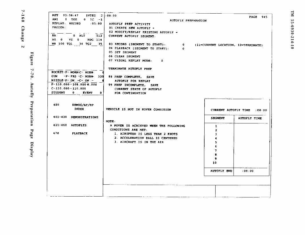
TM
55-6930-214-10
Figu
re 7-7
0.
Auto
fly Prep
aration
Page
Disp
lay
7-1
60
C
han
ge
2
TM 55-6930-214-10
7-62. TARGET ENGAGEMENT EXERCISE PREPARATION. The purpose of the TEE preparationfeature is to permit target engagement exercises to be prepared by selecting a setof target events to be simulated during a subsequent instructional activity andidentifying specific contingencies that, if met, during such instruction, willtrigger the insertion of each of the selected target events. Preparation of a TEEis preceded by the development of a tactical situation description or scenario.This scenario provides a context within which the intended target engagement in-structional activities can take place. It also permits the instructor to determinewhich target sites should be activated, what targets should be placed on each acti-vated site, when target events should be activated to be of most instructionalvalue, and the triggering contingencies that are both probable (as to occurrence)and realistic (as to circumstances of occurrence). There is computer space forpreparation and storage of 20 TEE’s in the CMS.
a. The major characteristics of each TEE are as follows:
(1) Each TEE can accomnodate up to 10 individual targets.
(2) Targets are selected from the 44 types on target list CRT pages 951A, 951Band 951C.
(3) A maximum of five targets per TEE can be assigned to travel over predeter-mined paths, and five can be assigned to fixed sites.
(4) Up to 15 events can be programmed for each TEE (events equal motion andhostile actions).
(5) Up to three sets of triggering contingencies can be defined for eachevent. (Contingencies include parameters and operators and. if more than one para-meter is selected, connectors required.)
(6) Specific aircraft malfunctions/systems failures can be assigned to eachhostile target; the failure occurs if the threat scores a hit on ownship.
(7) HOT or COLD IR coding can be assigned to each target (only stationarytargets can be IR COLD).
(8) For ground targets assigned to sites permitting motion, travel pathwayscan be selected, and vehicle speed from 0 to 40 kph, in 10-kph increments, can bedesignated.
(9) Five sites are designated for airborne targets only. When any of thesesites are assigned to a TEE, vehicle speed up to 200 kph can be designated.
b. In conjunction with the development of the scenario for the TEE, the instruc-tor should identify IC or autofly set(s) to be used with it. This is importantbecause using a specific IC or autofly set with a particular exercise will placethe simulated aircraft in the vicinity of the target sites to be activated and pro-vide an additional degree of standardization for the planned target engagementinstruction.
c. When CRT page 950 is called up via the data entry keyboard, the main pagearea contains a blank target engagement exercise prep page (figure 7-71) that iscompleted during the preparation process and then stored in group 5 (TARGETS, CRTpages 501 through 520) for recall during subsequent training periods. The data from
Change 2 7-161
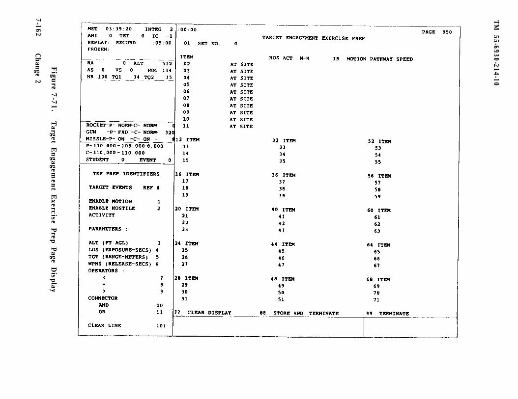
TM
55-6930-214-10
Figu
re 7-7
1.
Target E
ngagem
ent E
xercise Prep Page Display
7-162C
hange 2
TM 55-6930-214-10
the TEE worksheet (figure 7-72) should be entered on the appropriate lines of CRTpage 950. The index and control area (figure 7-71) includes the TEE PREP IDENTI-FIERS with reference numbers (REF #) for the TARGET EVENTS, PARAMETERS, OPERATORS,and CONNECTORS that are required for entry on the CRT page.
d. Line 01 (main page area, figure 7-71) is used to enter the identifying setnumber for the TEE. Command line 77 is used to clear the display and, when keyedIn, clears all data items entered. When a TEE prep is complete, keying commandline 88 places the data displayed on CRT page 950 in permanent storage in thetarget grouping where it is available for recall by its CRT page number (501through 520). Command line 99 is used to terminate (cancel) the preparationactivity; nothing is retained in storage when line 99 is keyed in.
e. On CRT page 950, there are four lines of data for each target In lines 02through 11. The first line for each target (lines 12, 16, 20, etc.) is for identi-fying the target site number from the target site list and the event reference num-ber from the Index and control area. The indented line numbers (13, 14, 15; 17,18. 19; etc.) are for insertion of the contingencies that will trigger the event.Up to three contingencies can be entered for each event. Each contingency lineaccommodates one parameter, one operator, and one connector, as required to definethe triggering activity. (The contingencies are further explained in the followingsubparagraph f.)
f . The index and control area of CRT page 950 (TEE PREP IDENTIFIERS, figure7-71) provides command reference numbers (REF #) so that titles and or multipleitems can be keyed In with a signal keystroke.
(1) Reference numbers 1 and 2 are used to key in the target event. Whenmotion (reference number 1) is enabled and the triggering contingencies have beenmet, the target travels over a predetermined path at a designated speed forapproximately 15 km and stops. When hostile activity (reference number 2) isenabled and the triggering contingencies have been met, the target fires at theownship. If a hit (malfunction code number) has been designated and the threatalgorithm concurs, a malfunction or system failure occurs with the hit.
(2) Reference numbers 3 through 6 are used to enter the appropriate triggeringparameters. When any reference number (3 through 6) is keyed in on a specificline, the parameter title appears on that line of CRT page 950. The appropriatemetrics for parameters are shown In the parenthetical note behind the parameter(e .g . , %, FT, KIAS, MINS, etc.). The following parameters can be assigned astriggering contingencies:
ALT AGL - Ownship altitudeLOS - Line-of-sight (intervisibility) between ownship and
target, measured in seconds of exposureTGT RANGE - Distance from ownship to target, measured in metersWPNS RELEASE - Firing/release of ownship weapons, measured in seconds
after release
(3) Reference numbers 7 through 9 are used to enter arithmetic operators ofless than, equal to, or greater than (<, =, >) the assigned value for thetriggering parameter. The assigned value must be keyed in after the associatedoperator reference number (e.g., 9 TAR 20 ENTER is the entry for greater than 20fee t ) . Each parameter must have an operator and a value assigned to trigger it.
Change 1 7-163

TM 55-6930-214-10
Figure 7-72. TEE Prep Data Worksheet (Sheet 1)
7-164 Change 2
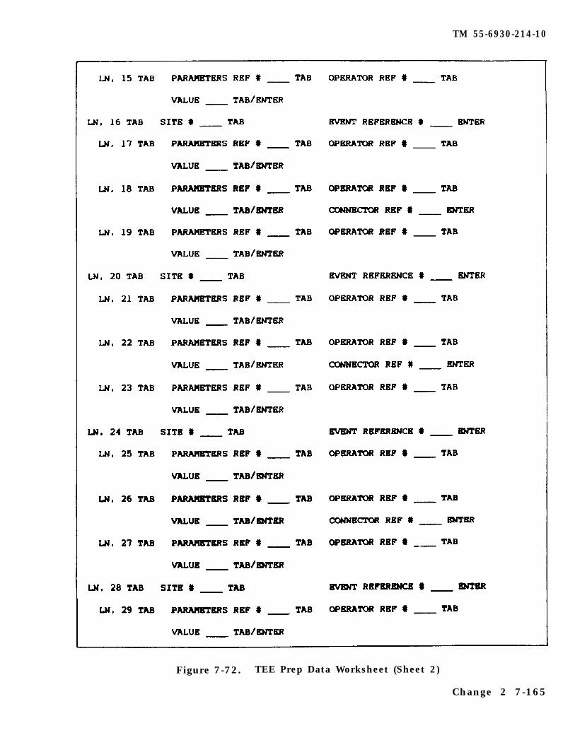
TM 55-6930-214-10
Figure 7-72. TEE Prep Data Worksheet (Sheet 2)
Change 2 7-165
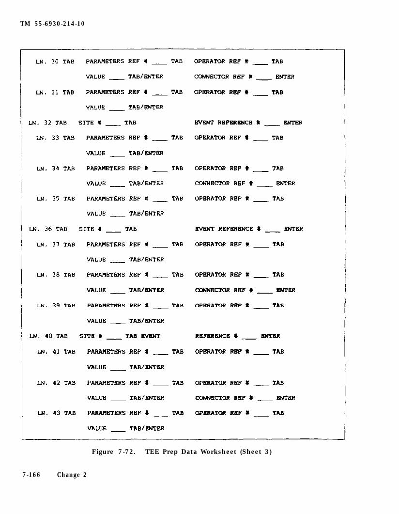
TM 55-6930-214-10
Figure 7-72. TEE Prep Data Worksheet (Sheet 3)
7-166 Change 2
TM 55-6930-214-10
Figure 7-72. TEE Prep Data worksheet (Sheet 4)
Change 2 7-167
TM 55-6930-214-10
Figure 7-72. TEE Prep Data Worksheet (Sheet 5)
7-168 Change 2
TM 55-6930-214-10
(4) Reference numbers 10 and 11 are used to enter logical connectors. If morethan one parameter is to be associated with an event, then a logical connector(AND, OR) must be designated for all but the last parameter. Reference numbers 10and 11 are used for these connectors. When AND is used as a connector, all para-meters connected with AND must be met to trigger the event. If OR is used as aconnector, any of the parameters connected by OR will trigger the event when it ismet.
(5) Reference number 101 is used to clear a line (e.g., 15 TAB 101 clears line15). When a line which has other lines dependent on it is cleared, the dependentlines are also cleared (e.g.. 16 TAB 101 clears lines, 16, 17. 18 and 19).
g. During TEE preparation functions, the edit area of the CRT page providesoperator prompts for data input and error messages for any out-of-range or invalidentries. Numerical inputs via the keyboard are echoed in the edit area with a cur-sor to indicate the next entry. When TAB is depressed between data fields, theappropriate data input appears on the first line of the edit area (e.g., when 02TAB is keyed in, the prompt appearing in the edit area states: ENTER TARGET TYPEREFERENCE NUMBER). (Target type reference numbers are listed on the target typeslist CRT page 951).
NOTE
If an error is made entering in data, an error message appearsin the edit area (e.g., ERROR - VALUE OUT OF RANGE). To correctthe error, depress the BACKSPACE or CLEAR keys to delete theentry, then insert the correct data.
h. Table 7-14 indicates the procedure required to enter the worksheet data intoCRT page 950 and the prompts and data displayed in the edit area. In the entrycolumn are the numbers to be entered plus the appropriate action key (e.g., DISPL,TAB, ENTER). The edit area displays column depicts three line entries to include(Blank) when nothing is shown and a line ( ) for the cursor mark. Lines 02through 06 accommodate entries for MOTION, PATHWAY, and SPEED. Lines 07 through 11have no MOTION prompts, so ENTER is keyed in after entering the IR code. Afterentering all the targets (lines 02 through 11) for a TEE, the triggering contin-gencies are then entered in lines 12 through 68. The procedure in table 7-14completes the required entries for the first target type, site associated activity,events, and two triggering contingencies. The process is repeated for eachadditional target until the TEE prep page is complete.
Each time ENTER is keyed in. the data in line 3 of the edit areablanks and the data appears on that numbered line in the mainpage area of the prep page.
Change 2 7-169
TM 55-6930-214-10
Table 7-14. TEE Prep Data Entry Procedure
Entry Edit area displays
1. To call up the TEE prep page, enter:
950 (Blank)950(Blank)
DISPL (Blank)
(Blank)
2. To assign a TEE set number, enter:
01 (Blank)01(Blank)
TAB ENTER SET NO.01(Blank)
NOTE
Each time TAB is keystroked, a prompt appears in the edit arearequesting specific data.
01 (Blank)01 01( B l a n k )
ENTER (Blank)
(Blank )
3. To enter the first target line, enter:
02 (Blank)02(Blank)
TAB ENTER TARGET TYPE REFERENCE NUMBER02(Blank)
3 ENTER TARGET TYPE REFERENCE NUMBER02 3(Blank)
7-170

TM 55-6930-214-10
Table 7-14. TEE Prep Data Entry Procedure - Continued
Entry Edit area displays
TAB ENTER PATHWAY SPEED (0 - 40 IN INCREMENTS OF 10)02 3 4 22205 1 1 3 20T-62 SITE 4 HOS ACT ON 22205 HOT MOTION ON PATH 3
20
ENTER
ENTER PATHWAY SPEED (0 - 40 IN INCREMENTS OF 10)02 3 4 22205 1 1 3 20T-62 SITE 4 HOS ACT ON 22205 HOT MOTION ON PATH 3
(Blank)
(Blank )
NOTE
Step 2. above completes the line entries required for the firsttarget. To enter additional targets in lines 03 through 11,repeat the procedure.
3. To enter the first event for TEE set No. 1, enter:
12 (Blank)12(Blank)
TAB ENTER SITE NUMBER12(Blank)
4 ENTER SITE NUMBER12 4(Blank)
TAB ENTER TARGET EVENT REFERENCE NUMBER12 4S I T E 4
2 ENTER TARGET EVENT REFERENCE NUMBER12 4 2SITE 4
ENTER (Blank)
(Blank)
7-171
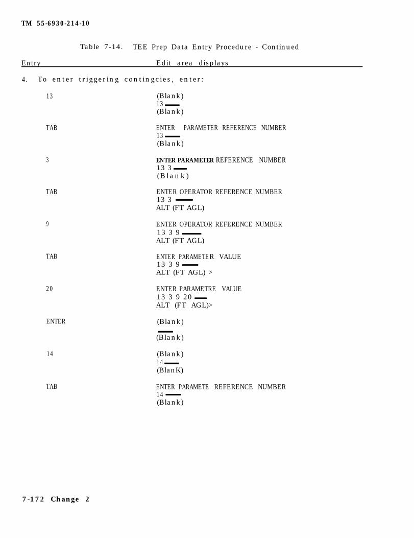
TM 55-6930-214-10
Table 7-14. TEE Prep Data Entry Procedure - Continued
Entry Edit area displays
4. To enter triggering contingcies, enter:
13 (Blank)13(Blank)
TAB
3
TAB
9
TAB
20
ENTER
14
TAB
ENTER PARAMETER REFERENCE NUMBER13(Blank)
ENTER PARAMETER REFERENCE NUMBER13 3(Blank)
ENTER OPERATOR REFERENCE NUMBER13 3ALT (FT AGL)
ENTER OPERATOR REFERENCE NUMBER13 3 9ALT (FT AGL)
ENTER PARAMETER VALUE13 3 9ALT (FT AGL) >
ENTER PARAMETRE VALUE13 3 9 20ALT (FT AGL)>
(Blank)
(Blank)
(Blank)14(BlanK)
ENTER PARAMETE REFERENCE NUMBER14(Blank)
7-172 Change 2
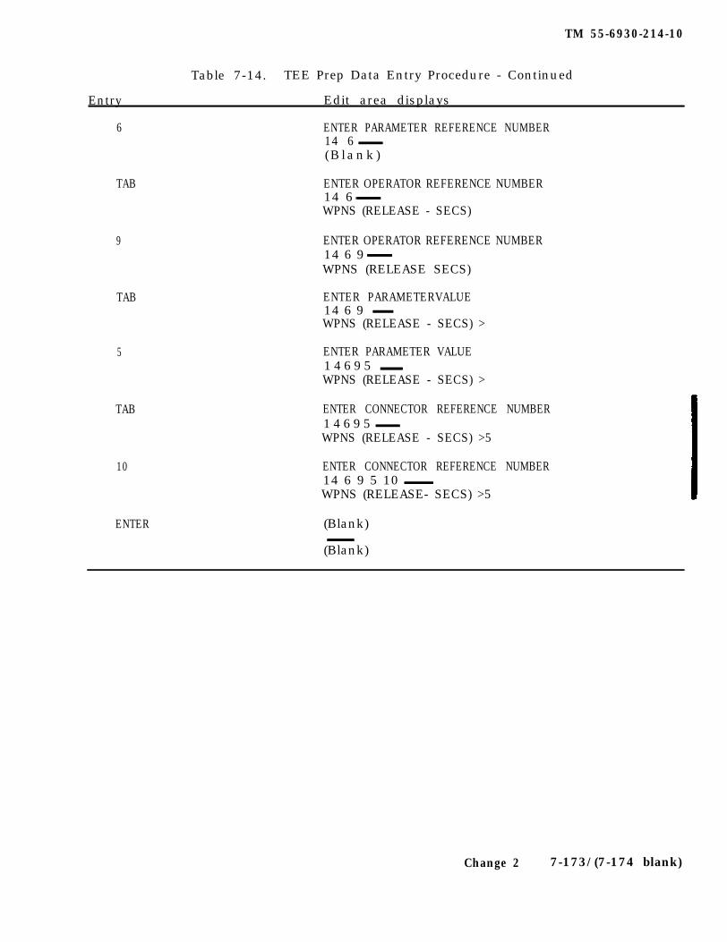
TM 55-6930-214-10
Entry
Table 7-14. TEE Prep Data Entry Procedure - Continued
Edit area displays
6 ENTER PARAMETER REFERENCE NUMBER14 6(B lank)
TAB ENTER OPERATOR REFERENCE NUMBER14 6WPNS (RELEASE - SECS)
9 ENTER OPERATOR REFERENCE NUMBER14 6 9WPNS (RELEASE SECS)
TAB
5
TAB
10
ENTER PARAMETERVALUE14 6 9WPNS (RELEASE - SECS) >
ENTER PARAMETER VALUE14695WPNS (RELEASE - SECS) >
ENTER CONNECTOR REFERENCE NUMBER14695WPNS (RELEASE - SECS) >5
ENTER CONNECTOR REFERENCE NUMBER14 6 9 5 10WPNS (RELEASE- SECS) >5
ENTER (Blank)
(Blank)
Change 2 7-173/(7-174 blank)

TM 55-6930-214-10
Section IV. SIMULATED MALFUNCTIONS
7-63. GENERAL. There are approximately 336 simulated malfunctions, systematicallyarranged on 29 CRT pages, available for the CMS. These pages are used to referencethe malfunction for selection and possible insertion into the training exercise.Malfuctions are entered into the simulated environment through the data entry key-board. Categories of available malfunctions are indexed by system on CRT page 200.
a. Active malfunctions are displayed in the status area, and up to six activemalfunctions are displayed at one time. Up to 15 malfunctions can be active at atime.
b. Individual malfunctions are coded with a specific 5-digit identifier made upof the number of the CRT page that it appears on (three digits) and the line number(two digits) on that CRT page. Typing the 5-digit identifier and depressing ENTERon the keyboard inserts the malfunction into simulation.
7-64. MALFUNCTION INSERTION. There are two ways of inserting malfunctions intothe simulated environment. One is manually, and the other uses automatic malfunc-tion insertion (AMI). There are 15 sets of AMI programs available, with up to 10malfunctions programmed for each one.
a. During simulation, a selected preprogrammed set of malfunctions can be auto-matically entered by choosing an AMI before or during training. Up to three dif-ferent contingent conditions/parameters can be designated for each malfunction. AnAMI can be inserted at the IOS CRT via the data entry keyboard.
b. Since the insertion of specific malfunctions is controlled and triggered byconditions that may be beyond instructor control. and the occurrence may disrupttraining or overload a trainee at that point, the instructor receives an alert mes-sage. Ten seconds prior to insertion of an AMI malfunction, an alert message withthe name of the malfunction flashes in the alert area of the CRT display. The in-structor has the option at this time to allow the malfunction insertion and to mon-itor trainee response, or to delete it. If the instructor decides to delete themalfunction, the MALF OVERRIDE switchlight on the forward control panel must be de-pressed. Depressing the switchlight deletes the impending malfunction for the re-mainder of the training period without affecting the remainder of the malfunctionsin the AMI set. Once an automatic malfunction has been overridden (deleted), ifthe Instructor desires, it can be inserted manually via the data entry keyboard.
7-65. MALFUNCTI0N DELETION. Active malfunctions can be deleted at any time byeither of the following methods:
a. Once Inserted, the malfunction can be removed by reentering the identifier.
b. Active malfunctions can also be removed by depressing the REM0VE ACTIVE MALFSswitchlight on the forward control panel.
7-66. CLEARING MALFUNCTI0NS. A11 malfunctions can be cleared by deletion exceptthe ones that trip circuit breakers (CB). Circuit breakers must be manually resetafter the malfunction has been deleted. When a CB malfunction is active, the cir-cuit breaker cannot be manually reset.
7-175

TM 55-6930-214-10
7-67. MALFUNCTION LIST. Table 7-15 lists the CRT line select numbers and descrip-tive titles of the available malfunctions. Primarily, the malfunctions are groupedby system in numerical order. Malfunction details In table 7-16 include the mal-function name as It appears on the CRT, the CRT reference number, aircraft indica-tions and related effects, the Indications presented to the instructor and trainee,and any corrective action that is required. The CRT reference number consists ofthe CRT page number (first three digits) and the CRT page line number (last twodigits).
7-176 Change 1
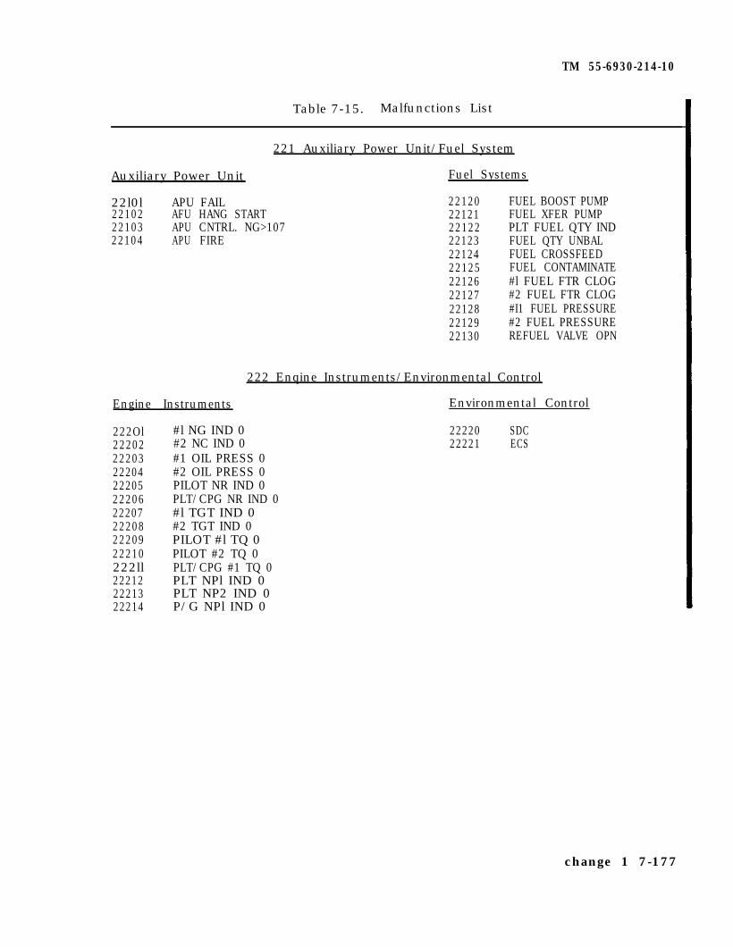
TM 55-6930-214-10
Table 7-15. Malfunctions List
221 Auxiliary Power Unit/Fuel System
Auxiliary Power Unit Fuel Systems
22l0l APU FAIL 2212022102 AFU HANG START 2212122103 APU CNTRL. NG>107 2212222104 APU FIRE 22123
22124221252212622127221282212922130
FUEL BOOST PUMPFUEL XFER PUMPPLT FUEL QTY INDFUEL QTY UNBALFUEL CROSSFEEDFUEL CONTAMINATE#l FUEL FTR CLOG#2 FUEL FTR CLOG#I1 FUEL PRESSURE#2 FUEL PRESSUREREFUEL VALVE OPN
222 Enqine Instruments/Environmental Control
Engine Instruments Environmental Control
222Ol #l NG IND 022202 #2 NC IND 022203 #1 OIL PRESS 022204 #2 OIL PRESS 022205 PILOT NR IND 022206 PLT/CPG NR IND 022207 #l TGT IND 022208 #2 TGT IND 022209 PILOT #l TQ 022210 PILOT #2 TQ 0222ll PLT/CPG #1 TQ 022212 PLT NPl IND 022213 PLT NP2 IND 022214 P/G NPl IND 0
22220 SDC22221 ECS
change 1 7-177
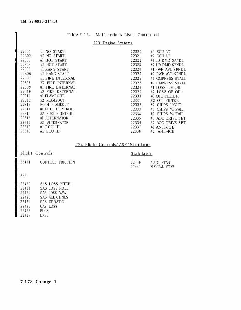
TM 55-6930-214-10
22301 #l NO START 2232022302 #2 NO START 2232122303 #l HOT START 2232222304 #2 HOT START 2232322305 #l RANG START 2232422306 #2 HANG START 2232522307 #l FIRE INTERNAL 2232622308 X2 FIRE INTERNAL 2232722309 #l FIRE EXTERNAL 2232822310 #2 FIRE EXTERNAL 2232922311 #l FLAMEOUT 2233022312 #2 FLAMEOUT 2233122313 BOTH FLAMEOUT 2233222314 #l FUEL CONTROL 2233322315 #2 FUEL CONTROL 2233422316 #l ALTERNATOR 2233522317 #2 ALTERNATOR 2233622318 #l ECU HI 2233722319 #2 ECU HI 22338
Table 7-15. Malfunctions List - Continued
223 Engine Systems
#1 ECU LO#2 ECU LO#l LD DMD SPNDL#2 LD DMD SPNDL#l PWR AVL SPNDL#2 PWR AVL SPNDL#1 CMPRESS STALL#2 CMPRESS STALL#l LOSS OF OIL#2 LOSS OF OIL#l OIL FILTER#2 OIL FILTER#2 CHIPS LIGHT#1 CHIPS W/FAIL#2 CHIPS W/FAIL#1 ACC DRIVE SET#2 ACC DRIVE SET#l ANTl-ICE#2 ANTI-ICE
224 Fliqht Controls/ASE/Stabllator
Fliqht Controls Stabilator
22401 CONTROL FRICTION 22440 AUTO STAB22441 MANUAL STAB
ASE
22420 SAS LOSS PITCH22421 SAS LOSS ROLL22422 SAS LOSS YAW22423 SAS ALL CHNLS22424 SAS ERRATIC22425 CAS LOSS22426 BUCS22427 DASE
7-178 Change 1

TM 55-6930-214-10
Table 7-15. Malfunctions List - Continued
225 Transmission/Rotor
Transmission
22501 #l XMSN OIL PRESS22502 #2 XMSN OIL PRESS22503 #l XMSN COOLER22504 #2 XMSN COOLER22505 #1 OIL QTY LOW22506 #2 OIL QTY LOW22507 MAIN XMSN CHIPS22508 #1 INPT DRIV SFT22509 #2 INPT DRIV SFT22510 ACC DRIVE GBX22511 #l NOSE GBX PUMP22512 #2 NOSE GBX PUMP22513 #l NOSE GBX HOT22514 #2 NOSE GBX HOT22515 #l NOSE GBX CHIP22516 #2 NOSE GBX CHIP22517 GBX VIBRATION22518 COOLING FAN
Electrical
22601 BATTERY RELAY22602 HOT BATTERY22603 BATTERY CHARGER22604 #1 AC GENERATOR22605 #2 AC GENERATOR22606 BOTH AC GENS22607 #l AC CONTACTOR22608 #2 AC CONTACTOR226O9 DC CONTACTOR22610 PLT FLT INST LT22611 CPG FLT INST LT22612 #l TRU22613 #2 TRU22614 BOTH TRU'S22615 #l TRU HOT22616 #2 TRU HOT
Rotor
22520 MRTR OUT OF TRK22521 MRTR OUT OF BAL22522 BLADEDAMPER22523 RTR BK ENG FLT22524 TLRTR BLADE LOSS22525 TLRTR GBX LOSS22526 TRTR THRUST LOSS22527 TLRTR FIXED22528 TLRTR OUT OF TRK
226 Electrical/Hydraulic
Hydraulic
22620 PRI HYD22621 UTIL HYD22622 BOTH HYD22623 PRI HYD OIL LOU22624 UTIL HYD OIL LOW22625 PRI HYD FILTER22626 UTIL HYD FILTER22627 UTIL ACCUM PRESS22628 LEFT BRAKE22629 RIGHT BRAKE22630 TAILWHEEL LOCK
Change 1 7-179
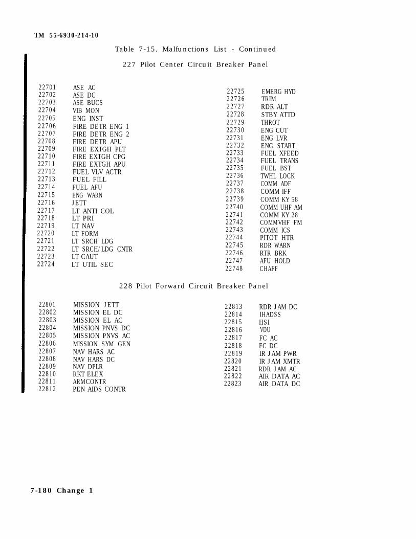
TM 55-6930-214-10
22701 ASE AC22702 ASE DC22703 ASE BUCS22704 VIB MON22705 ENG INST22706 FIRE DETR ENG 122707 FIRE DETR ENG 222708 FIRE DETR APU22709 FIRE EXTGH PLT22710 FIRE EXTGH CPG22711 FIRE EXTGH APU22712 FUEL VLV ACTR22713 FUEL FILL22714 FUEL AFU22715 ENG WARN22716 JETT22717 LT ANTI COL22718 LT PRI22719 LT NAV22720 LT FORM22721 LT SRCH LDG22722 LT SRCH/LDG CNTR22723 LT CAUT22724 LT UTIL SEC
228 Pilot Forward Circuit Breaker Panel
22801 MISSION JETT22802 MISSION EL DC22803 MISSION EL AC22804 MISSION PNVS DC22805 MISSION PNVS AC22806 MISSION SYM GEN22807 NAV HARS AC22808 NAV HARS DC22809 NAV DPLR22810 RKT ELEX22811 ARMCONTR22812 PEN AIDS CONTR
Table 7-15. Malfunctions List - Continued
227 Pilot Center Circuit Breaker Panel
22725 EMERG HYD22726 TRIM22727 RDR ALT22728 STBY ATTD22729 THROT22730 ENG CUT22731 ENG LVR22732 ENG START22733 FUEL XFEED22734 FUEL TRANS22735 FUEL BST22736 TWHL LOCK22737 COMM ADF22738 COMM IFF22739 COMM KY 5822740 COMM UHF AM22741 COMM KY 2822742 COMMVHF FM22743 COMM ICS22744 PITOT HTR22745 RDR WARN22746 RTR BRK22747 AFU HOLD22748 CHAFF
22813 RDR JAM DC22814 IHADSS22815 HSI22816 VDU22817 FC AC22818 FC DC22819 IR JAM PWR22820 IR JAM XMTR22821 RDR JAM AC22822 AIR DATA AC22823 AIR DATA DC
7-180 Change 1
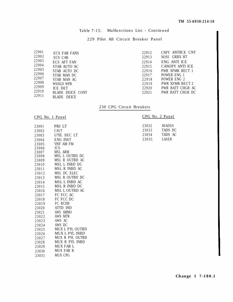
TM 55-6930-214-10
2290122902229032290422905229062290722908229092291022911
Table 7-15. Malfunctions List - Continued
229 Pilot Aft Circuit Breaker Panel
ECS FAB FANS 22912 CNPY ANTIICE CNTECS CAB 22913 NOSE GRBX HTECS AFT FANSTAB AUTO ACSTAB AUTO DCSTAB MAN DCSTAB MAN ACWSHLD WPRICE DETBLADE DEICE CONTBLADE DEICE
CPG No. 1 Panel CPG NO. 2 Panel
23001230022300323004230052300623007230082300923010230112301223013230142301523016230172301823019230202302123022230232302423025230262302723028230292303023031
PRI LTCAUTUTIL SEC LTENG INSTVHF AM FMICSMSL ARMMSL L OUTBD DCMSL R OUTBD ACMSL L INBD DCMSL R INBD ACMSL DC ELECMSL R OUTBD DCMSL L INBD ACMSL R INBD DCMSL L OUTBD ACFC FCC ACFC FCC DCFC RCDRATTD INDAWS AMMOAWS MTRAWS ACAWS DCMUX L PYL OUTBDMUX L PYL INBDMUX R PYL OUTBDMUX R PYL INBDMUX FAB LMUX FAB RMUX CPG
22914 ENG ANTI ICE22915 CANOPY ANTI ICE22916 PWR XFMR RECT 122917 POWER ENG 122918 POWER ENG 222919 PWR XFMR RECT 222920 PWR BATT CHGR AC22921 PWR BATT CHGR DC
230 CPG Circuit Breakers
23032 IHADSS23033 TADS DC23034 TADS AC23035 LASER
Change 1 7-180.1
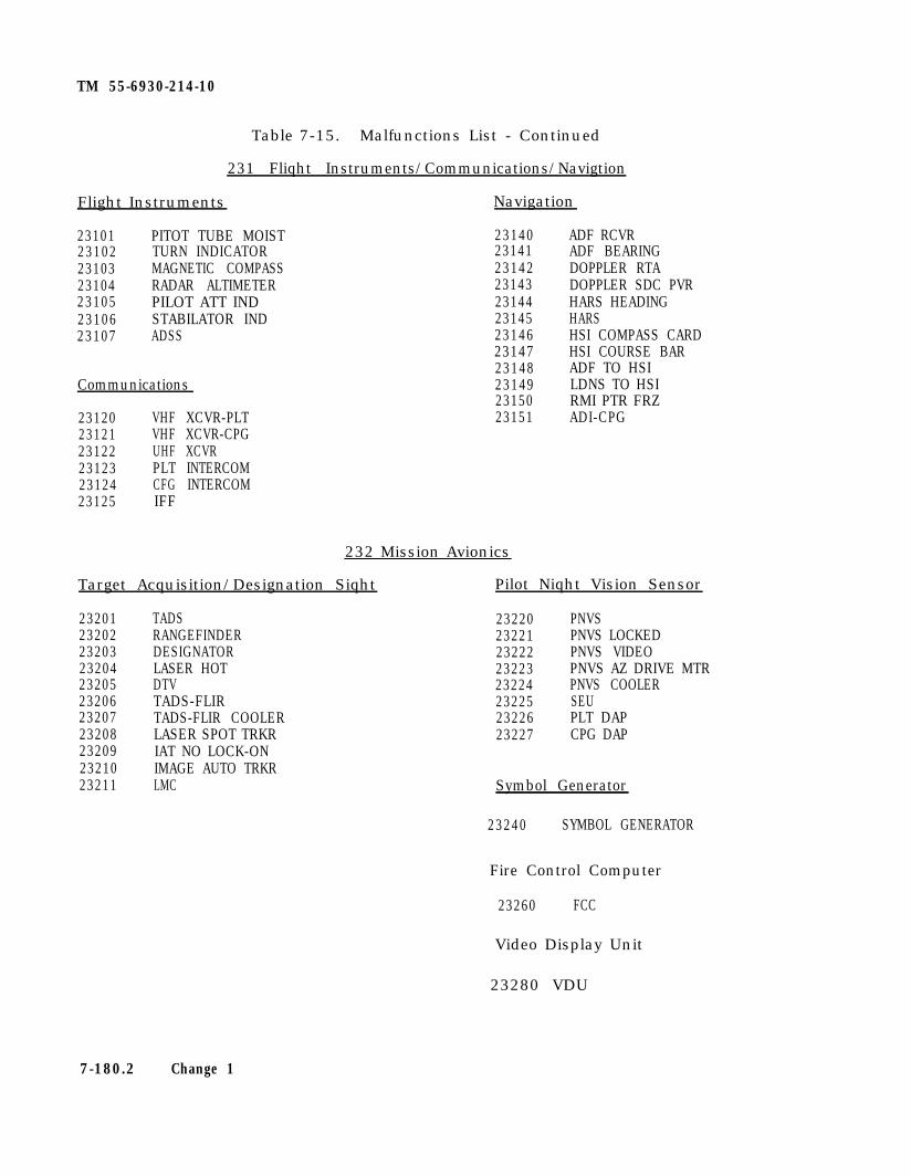
TM 55-6930-214-10
Table 7-15. Malfunctions List - Continued
231 Fliqht Instruments/Communications/Navigtion
Flight Instruments Navigation
23101 PITOT TUBE MOIST23102 TURN INDICATOR23103 MAGNETIC COMPASS23104 RADAR ALTIMETER23105 PILOT ATT IND23106 STABILATOR IND23107 ADSS
23140 ADF RCVR23141 ADF BEARING23142 DOPPLER RTA23143 DOPPLER SDC PVR23144 HARS HEADING23145 HARS23146 HSI COMPASS CARD23147 HSI COURSE BAR23148 ADF TO HSI23149 LDNS TO HSI23150 RMI PTR FRZ23151 ADI-CPG
Communications
23120 VHF XCVR-PLT23121 VHF XCVR-CPG23122 UHF XCVR23123 PLT INTERCOM23124 CFG INTERCOM23125 IFF
232 Mission Avionics
Target Acquisition/Designation Siqht Pilot Niqht Vision Sensor
23201 TADS23202 RANGEFINDER23203 DESIGNATOR23204 LASER HOT23205 DTV23206 TADS-FLIR23207 TADS-FLIR COOLER23208 LASER SPOT TRKR23209 IAT NO LOCK-ON23210 IMAGE AUTO TRKR23211 LMC
23220 PNVS23221 PNVS LOCKED23222 PNVS VIDEO23223 PNVS AZ DRIVE MTR23224 PNVS COOLER23225 SEU23226 PLT DAP23227 CPG DAP
Symbol Generator
23240 SYMBOL GENERATOR
Fire Control Computer
23260 FCC
Video Display Unit
23280 VDU
7-180.2 Change 1
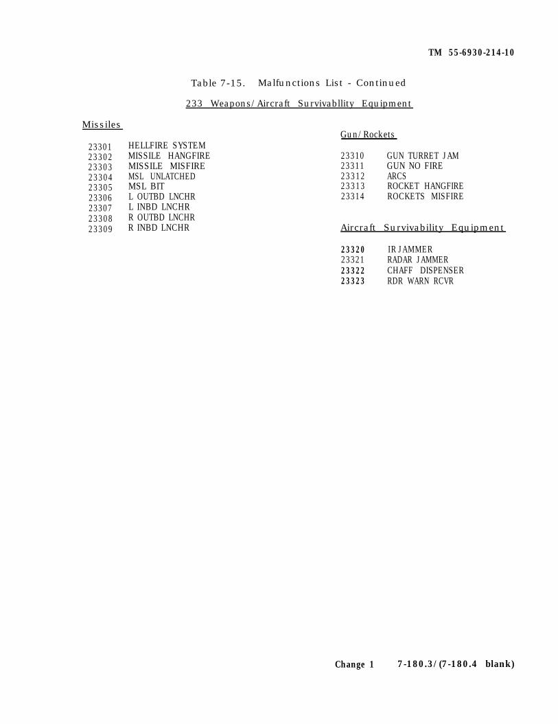
TM 55-6930-214-10
Missiles
233012330223303233042330523306233072330823309
Table 7-15. Malfunctions List - Continued
233 Weapons/Aircraft Survivabllity Equipment
HELLFIRE SYSTEMMISSILE HANGFIREMISSILE MISFIREMSL UNLATCHEDMSL BITL OUTBD LNCHRL INBD LNCHRR OUTBD LNCHRR INBD LNCHR
Gun/Rockets
23310 GUN TURRET JAM23311 GUN NO FIRE23312 ARCS23313 ROCKET HANGFIRE23314 ROCKETS MISFIRE
Aircraft Survivability Equipment
23320 IR JAMMER23321 RADAR JAMMER23322 CHAFF DISPENSER23323 RDR WARN RCVR
Change 1 7-180.3/(7-180.4 blank)

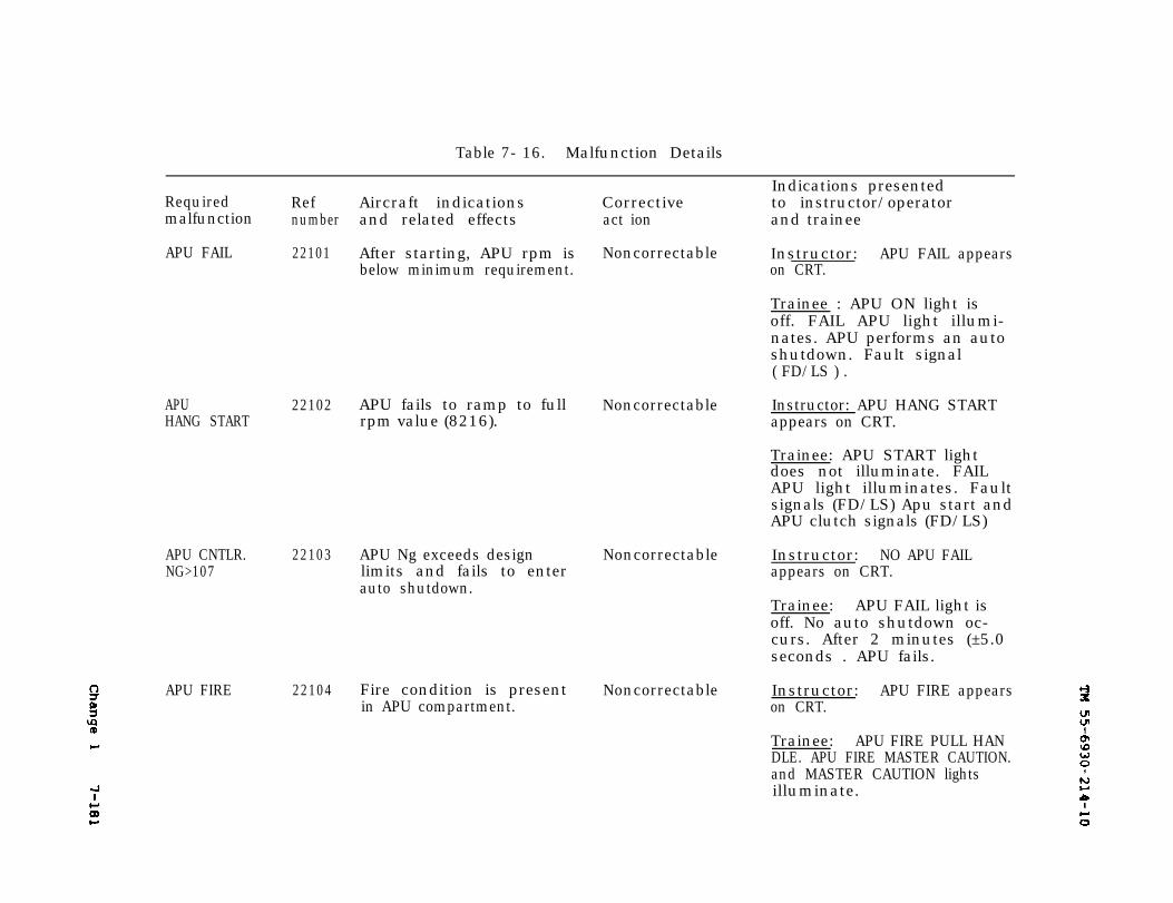
Change 1
7-182
TM 55-6930-214-10
Table 7- 16. Malfunction Details
Required Ref Aircraft indicationsmalfunction number and related effects
APU FAIL 22101
APUHANG START
22102
APU CNTLR. 22103NG>107
APU FIRE 22104
After starting, APU rpm isbelow minimum requirement.
APU fails to ramp to fullrpm value (8216).
APU Ng exceeds designlimits and fails to enterauto shutdown.
Fire condition is presentin APU compartment.
Correctiveact ion
Noncorrectable
Indications presentedto instructor/operatorand trainee
Instructor: APU FAIL appearson CRT.
Trainee : APU ON light isoff. FAIL APU light illumi-nates. APU performs an autoshutdown. Fault signal( FD/LS ) .
Noncorrectable Instructor: APU HANG STARTappears on CRT.
Trainee: APU START lightdoes not illuminate. FAILAPU light illuminates. Faultsignals (FD/LS) Apu start andAPU clutch signals (FD/LS)
Noncorrectable Instructor: NO APU FAILappears on CRT.
Trainee: APU FAIL light isoff. No auto shutdown oc-curs. After 2 minutes (±5.0seconds . APU fails.
Noncorrectable Instructor: APU FIRE appearson CRT.
Trainee: APU FIRE PULL HANDLE. APU FIRE MASTER CAUTION.and MASTER CAUTION lightsilluminate.
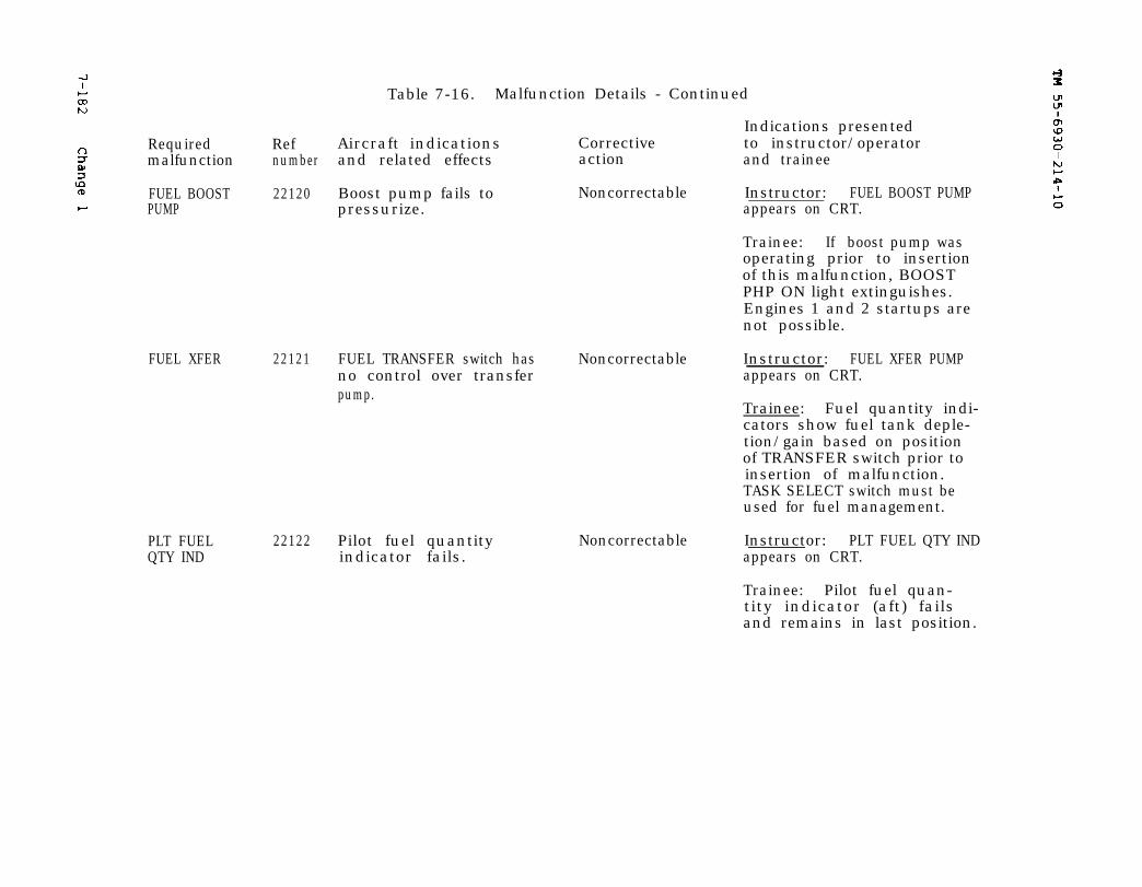
TM 55-6930-214-10
7-182
Change 1
TM 55-6390-214-10
7-182
Change 1
Table 7-16. Malfunction Details - Continued
Indications presentedRequired Ref Aircraft indications Corrective to instructor/operatormalfunction number and related effects action and trainee
FUEL BOOST 22120 Boost pump fails to Noncorrectable Instructor: FUEL BOOST PUMPPUMP pressurize. appears on CRT.
Trainee: If boost pump wasoperating prior to insertionof this malfunction, BOOSTPHP ON light extinguishes.Engines 1 and 2 startups arenot possible.
FUEL XFER 22121 FUEL TRANSFER switch has Noncorrectable Instructor: FUEL XFER PUMPno control over transfer appears on CRT.pump.
Trainee: Fuel quantity indi-cators show fuel tank deple-tion/gain based on positionof TRANSFER switch prior toinsertion of malfunction.TASK SELECT switch must beused for fuel management.
PLT FUEL 22122 Pilot fuel quantityQTY IND indicator fails.
Noncorrectable Instructor: PLT FUEL QTY INDappears on CRT.
Trainee: Pilot fuel quan-tity indicator (aft) failsand remains in last position.

TM 55-6930-214-10
Change 1
7-182
Table 7-16. Malfunction Details - Continued
Indications presentedRequired Ref Aircraft indications Corrective to instructor/operatormalfunction number and related effects action and trainee
FUEL QTYUNBAL
22123 Unbalanced fuel burning Noncorrectable Instructor: FUEL QTY UNBALin forward tank after 30 appears on CRT.minutes operation (depend-ing on when malfunction is Trainee : FUEL LOU light il-inserted). luminates on pilot and CPG
caution panels. Fuel quanti-ty gages reflect fuel status.
FUELCROSSFEED
22124 FUEL CROSSFEED switch has Noncorrectable Instructor: FUEL CROSSFEEDno control over position appears on CRT.of crossfeed valve.
Trainee : Fuel quantity indi-cators show fuel depletionfrom appropriate tank basedon position prior to inser-tion of malfunction.
FUEL 22125 Unsuccessful fuel use.CONTAMINATE
Noncorrectable
#l FUEL FTR 22126 Engine 1 fuel filter be- NoncorrectableCLOG comes clogged and is by-
passed.
Instructor : FUEL CONTAMINATEappears on CRT.
Trainee : FUEL BYP ENG 1light illuminates. followed30 seconds later by FUEL BYPENG 2. Engine power mayfluctuate.
Instructor: #l FUEL FTR CLOGappears on CRT.
Trainee: Fuel bypass ENG 1light illuminates.
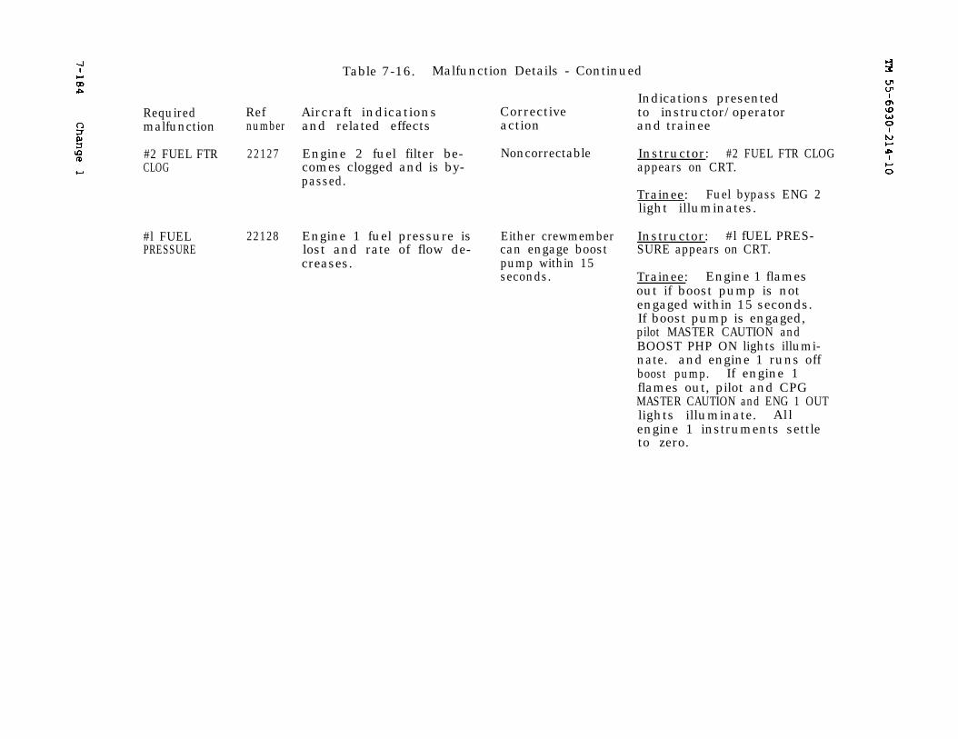
7-184
Change 1
TM 55-6930-214-10
Table 7-16. Malfunction Details - Continued
Indications presentedRequired Ref Aircraft indications Corrective to instructor/operatormalfunction number and related effects action and trainee
#2 FUEL FTR 22127 Engine 2 fuel filter be- Noncorrectable Instructor: #2 FUEL FTR CLOGCLOG comes clogged and is by- appears on CRT.
passed.Trainee: Fuel bypass ENG 2light illuminates.
#l FUELPRESSURE
22128 Engine 1 fuel pressure is Either crewmember Instructor: #l fUEL PRES-lost and rate of flow de- can engage boost SURE appears on CRT.creases. pump within 15
seconds. Trainee: Engine 1 flamesout if boost pump is notengaged within 15 seconds.If boost pump is engaged,pilot MASTER CAUTION andBOOST PHP ON lights illumi-nate. and engine 1 runs offboost pump. If engine 1flames out, pilot and CPGMASTER CAUTION and ENG 1 OUTlights illuminate. Allengine 1 instruments settleto zero.
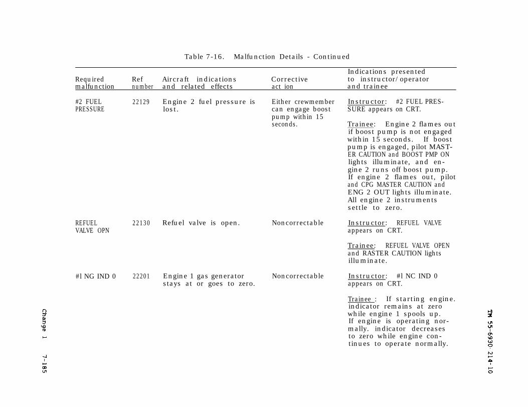
7-185
TM 55-6930-214-10
Change 1
Table 7-16. Malfunction Details - Continued
Indications presentedRequired Ref Aircraft indications Corrective to instructor/operatormalfunction number and related effects act ion and trainee
#2 FUELPRESSURE
22129 Engine 2 fuel pressure is Either crewmember Instructor: #2 FUEL PRES-lost. can engage boost SURE appears on CRT.
pump within 15seconds. Trainee: Engine 2 flames out
if boost pump is not engagedwithin 15 seconds. If boostpump is engaged, pilot MAST-ER CAUTION and BOOST PMP ONlights illuminate, and en-gine 2 runs off boost pump.If engine 2 flames out, pilotand CPG MASTER CAUTION andENG 2 OUT lights illuminate.All engine 2 instrumentssettle to zero.
REFUELVALVE OPN
22130 Refuel valve is open. Noncorrectable Instructor: REFUEL VALVEappears on CRT.
Trainee: REFUEL VALVE OPENand RASTER CAUTION lightsilluminate.
#l NG IND 0 22201 Engine 1 gas generator Noncorrectable Instructor: #l NC IND 0stays at or goes to zero. appears on CRT.
Trainee : If starting engine.indicator remains at zerowhile engine 1 spools up.If engine is operating nor-mally. indicator decreasesto zero while engine con-tinues to operate normally.
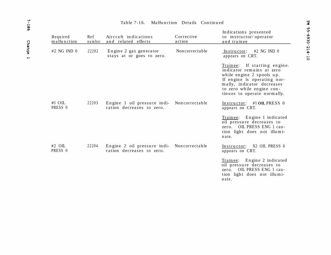
TM 66-6930-214-10
7-186
Change 1
Table 7-16. Malfunction Details Continued
Indications presentedRequired Ref Aircraft indications Corrective to instructor/operatormalfunction number and related effects action and trainee
#2 NG IND 0 22202
#l OILPRESS 0
22203
#2 OILPRESS 0
22204
Engine 2 gas generator Noncorrectable Instructor: #2 NG IND 0stays at or goes to zero. appears on CRT.
Trainee: If starting engine.indicator remains at zerowhile engine 2 spools up.If engine is operating nor-mally, indicator decreasesto zero while engine con-tinues to operate normally.
Engine 1 oil pressure indi- Noncorrectable Instructor: #l OIL PRESS 0cation decreases to zero. appears on CRT.
Trainee: Engine 1 indicatedoil pressure decreases tozero. OIL PRESS ENG 1 cau-tion light does not illumi-nate.
Engine 2 oil pressure indi- Noncorrectable Instructor: X2 OIL PRESS 0cation decreases to zero. appears on CRT.
Trainee: Engine 2 indicatedoil pressure decreases tozero. OIL PRESS ENG 1 cau-tion light does not illumi-nate.
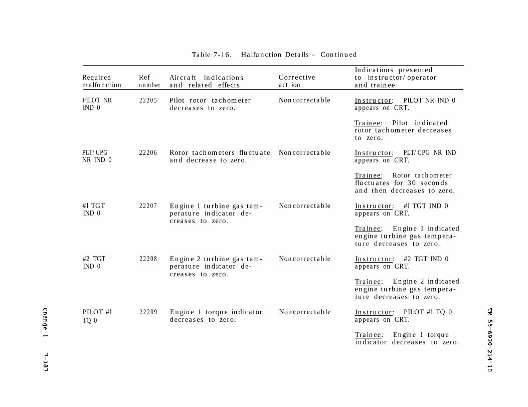
7-187
TM 55-6930-214-10
Change 1
Table 7-16. Halfunction Details - Continued
Required Ref Aircraft indications Correctivemalfunction number and related effects act ion
PILOT NRIND 0
PLT/CPGNR IND 0
#l TGTIND 0
#2 TGTIND 0
PILOT #lTQ 0
22205
22206
22207
22208
22209
Pilot rotor tachometerdecreases to zero.
Noncorrectable
Rotor tachometers fluctuate Noncorrectable Instructor: PLT/CPG NR INDand decrease to zero. appears on CRT.
Engine 1 turbine gas tem-perature indicator de-creases to zero.
Engine 2 turbine gas tem-perature indicator de-creases to zero.
Engine 1 torque indicatordecreases to zero.
Noncorrectable
Noncorrectable
Noncorrectable
Indications presentedto instructor/operatorand trainee
Instructor: PILOT NR IND 0appears on CRT.
Trainee: Pilot indicatedrotor tachometer decreasesto zero.
Trainee: Rotor tachometerfluctuates for 30 secondsand then decreases to zero.
Instructor: #l TGT IND 0appears on CRT.
Trainee: Engine 1 indicatedengine turbine gas tempera-ture decreases to zero.
Instructor: #2 TGT IND 0appears on CRT.
Trainee: Engine 2 indicatedengine turbine gas tempera-ture decreases to zero.
Instructor: PILOT #l TQ 0appears on CRT.
Trainee: Engine 1 torqueindicator decreases to zero.
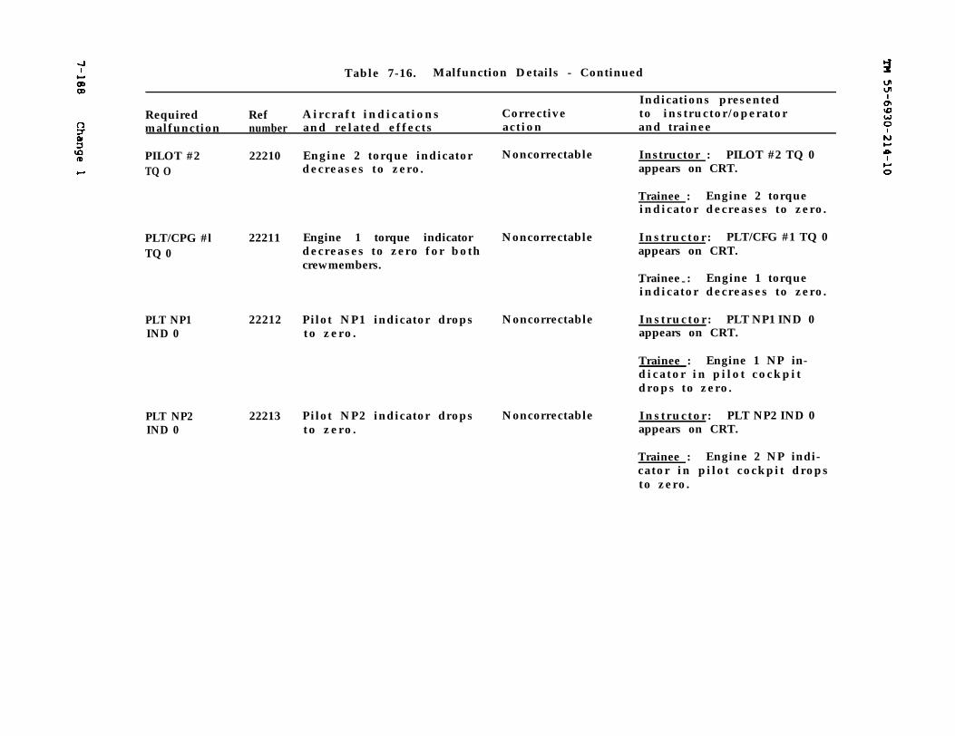
TM 55-6930-214-10
7-188
Change 1
Table 7-16. Malfunction Details - Continued
Indications presentedRequired Ref A i r c r a f t i n d i c a t i o n s Corrective to instructor/operatormalfunction number and related effects action and trainee
PILOT #2TQ O
22210 Engine 2 torque indicatordecreases to zero.
Noncorrectable Instructor : PILOT #2 TQ 0appears on CRT.
Trainee : Engine 2 torqueindicator decreases to zero.
PLT/CPG #lTQ 0
PLT NP1 22212 Pilot NP1 indicator dropsIND 0 t o z e r o .
PLT NP2IND 0
22211 Engine 1 torque indicatordecreases to zero for bothcrewmembers.
22213 Pilot NP2 indicator dropst o z e r o .
Noncorrectable Ins t ruc tor : PLT/CFG #1 TQ 0appears on CRT.
Trainee :- - Engine 1 torqueindicator decreases to zero.
Noncorrectable Ins t ruc tor : PLT NP1 IND 0appears on CRT.
Trainee : Engine 1 NP in-d i c a t o r i n p i l o t c o c k p i tdrops to zero.
Noncorrectable Ins t ruc tor : PLT NP2 IND 0appears on CRT.
Trainee : Engine 2 NP indi-cator in pilot cockpit dropsto zero.
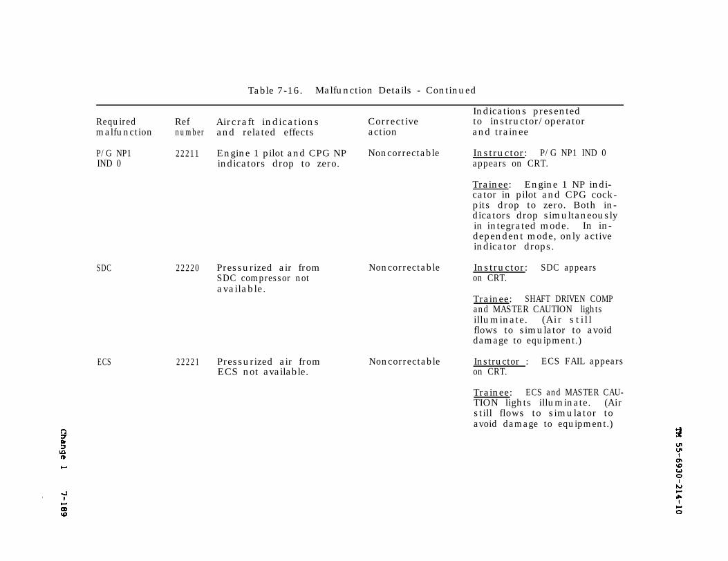
TM 55-6930-214-10
Change 1
7-189
Table 7-16. Malfunction Details - Continued
Indications presentedRequired Ref Aircraft indications Corrective to instructor/operatormalfunction number and related effects action and trainee
P/G NP1 22211 Engine 1 pilot and CPG NP Noncorrectable Instructor: P/G NP1 IND 0IND 0 indicators drop to zero. appears on CRT.
Trainee: Engine 1 NP indi-cator in pilot and CPG cock-pits drop to zero. Both in-dicators drop simultaneouslyin integrated mode. In in-dependent mode, only activeindicator drops.
SDC
ECS
22220 Pressurized air fromSDC compressor notavailable.
22221 Pressurized air fromECS not available.
Noncorrectable Instructor: SDC appearson CRT.
Trainee: SHAFT DRIVEN COMPand MASTER CAUTION lightsilluminate. (Air sti l lflows to simulator to avoiddamage to equipment.)
Noncorrectable Instructor : ECS FAIL appearson CRT.
Trainee: ECS and MASTER CAU-TION lights illuminate. (Airstill flows to simulator toavoid damage to equipment.)
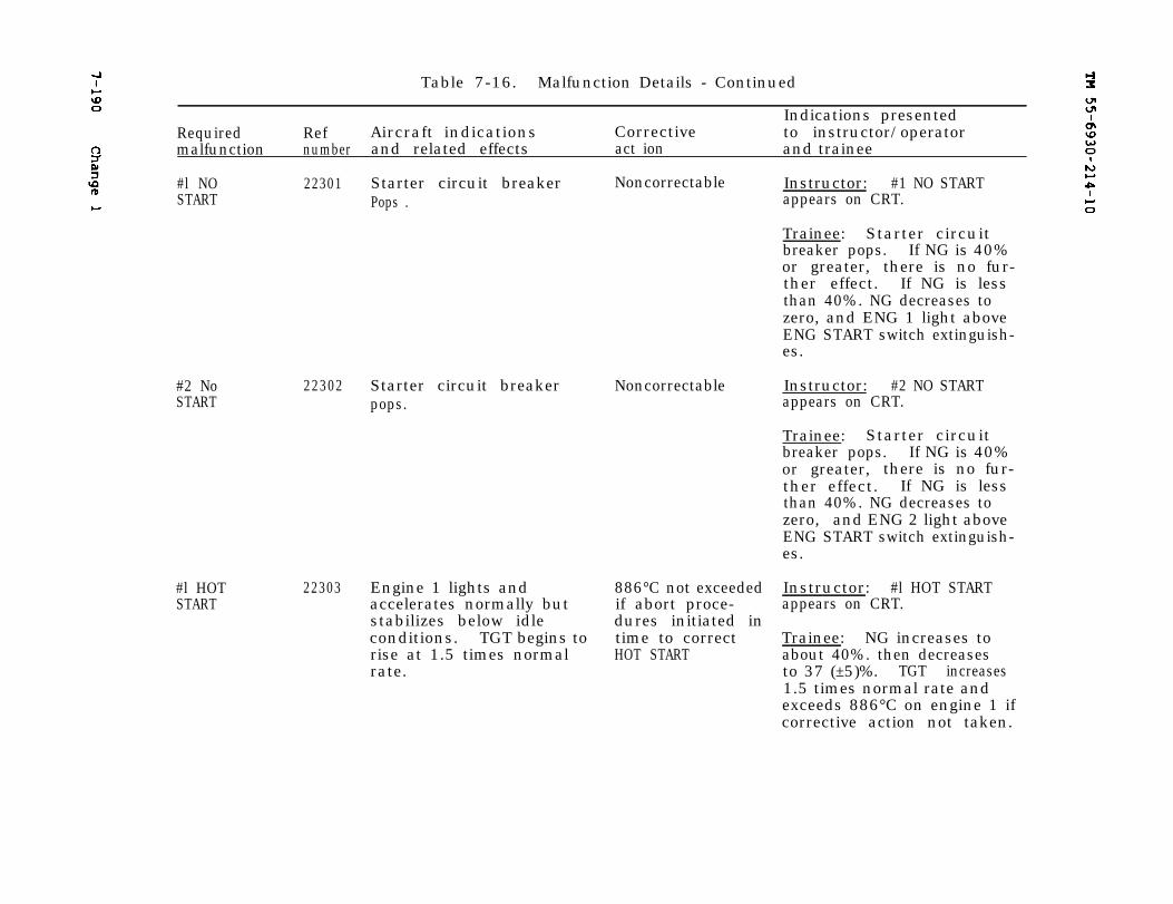
7-190
TM 55-6930-214-10
Change 1
Table 7-16. Malfunction Details - Continued
Indications presentedRequired Ref Aircraft indications Corrective to instructor/operatormalfunction number and related effects act ion and trainee
#l NO 22301 Starter circuit breakerSTART Pops .
#2 NoSTART
#l HOTSTART
22302 Starter circuit breakerpops.
22303 Engine 1 lights andaccelerates normally butstabilizes below idleconditions. TGT begins torise at 1.5 times normalrate.
Noncorrectable Instructor: #1 NO STARTappears on CRT.
Trainee: Starter circuitbreaker pops. If NG is 40%or greater, there is no fur-ther effect. If NG is lessthan 40%. NG decreases tozero, and ENG 1 light aboveENG START switch extinguish-es.
Noncorrectable Instructor: #2 NO STARTappears on CRT.
Trainee: Starter circuitbreaker pops. If NG is 40%or greater, there is no fur-ther effect. If NG is lessthan 40%. NG decreases tozero, and ENG 2 light aboveENG START switch extinguish-es.
886°C not exceeded Instructor: #l HOT STARTif abort proce- appears on CRT.dures initiated intime to correct Trainee: NG increases toHOT START about 40%. then decreases
to 37 (±5)%. TGT increases1.5 times normal rate andexceeds 886°C on engine 1 ifcorrective action not taken.
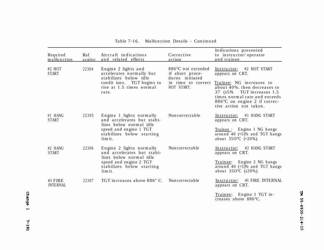
Change 1
TM 55-6930-214-10
7-191
Table 7-16. Malfunction Details - Continued
Indications presentedRequired Ref Aircraft indications Corrective to instructor/operatormalfunction number and related effects action and trainee
#1 HANGSTART
22305 Engine 1 lights normally Noncorrectableand accelerates but stabi-lizes below normal idlespeed and engine 1 TGTstabilizes below startinglimit.
#2 HANGSTART
22306 Engine 2 lights normally Noncorrectableand accelerates but stabi-lizes below normal idlespeed and engine 2 TGTstabilizes below startinglimit.
#l FIREINTERNAL
22307 TGT increases above 886º C. Noncorrectable
#2 HOTSTART
22304 Engine 2 lights andaccelerates normally butstabilizes below idlecondit ions. TGT begins torise at 1.5 times normalrate.
886°C not exceeded Instructor: #2 HOT STARTif abort proce- appears on CRT.dures initiatedin time to correct Trainee: NG increases toHOT START. about 40%. then decreases to
37 (±5N. TGT increases 1.5times normal rate and exceeds886°C on engine 2 if correc-tive action not taken.
Instructor: #1 HANG STARTappears on CRT.
Trainee : Engine 1 NG hangsaround 40 (+5)% and TGT hangsabout 35O°C (+20%).
Instructor: #2 HANG STARTappears on CRT.
Trainee: Engine 2 NG hangsaround 40 (+5)% and TGT hangsabout 35O°C (±20%).
Instructor: #l FIRE INTERNALappears on CRT.
Trainee: Engine 1 TGT in-creases above 886°C.
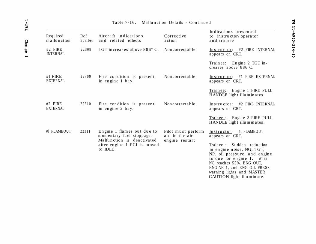
7-192
Change 1
TM 55-6930-214-10
Table 7-16. Malfunction Details - Continued
Indications presentedRequired Ref Aircraft indications Corrective to instructor/operatormalfunction number and related effects action and trainee
#2 FIRE 22308 TGT increases above 886° C. Noncorrectable Instructor: #2 FIRE INTERNALINTERNAL appears on CRT.
#l FIRE 22309 Fire condition is present NoncorrectableEXTERNAL in engine 1 bay.
#2 FIREEXTERNAL
22310 Fire condition is present Noncorrectablein engine 2 bay.
Trainee: Engine 2 TGT in-creases above 886°C.
Instructor: #1 FIRE EXTERNALappears on CRT.
Trainee: Engine 1 FIRE PULLHANDLE light illuminates.
Instructor: #2 FIRE INTERNALappears on CRT.
Trainee : Engine 2 FIRE PULLHANDLE light illuminates.
#l FLAMEOUT 22311 Engine 1 flames out due to Pilot must perform Instructor: #l FLAMEOUTmomentary fuel stoppage. an in-the-air appears on CRT.Malfunction is deactivated engine restartafter engine 1 PCL is moved Trainee : Sudden reductionto IDLE. in engine noise, NG, TGT,
NP. oil pressure, and enginetorque for engine 1. WhenNG reaches 55%. ENG OUT,ENGINE 1, and ENG OIL PRESSwarning lights and MASTERCAUTION light illuminate.
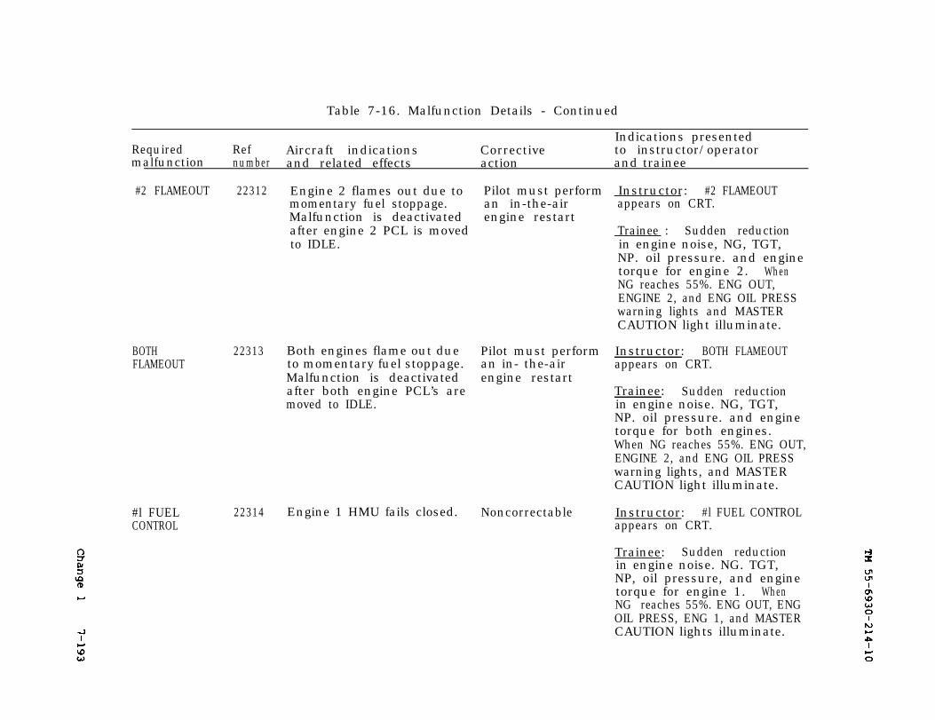
Change 1
TM 55-6930-214-10
7-193
Table 7-16. Malfunction Details - Continued
Indications presentedRequired Ref Aircraft indications Corrective to instructor/operatormalfunction number and related effects action and trainee
#2 FLAMEOUT 22312 Engine 2 flames out due to Pilot must perform Instructor: #2 FLAMEOUTmomentary fuel stoppage. an in-the-air appears on CRT.Malfunction is deactivated engine restartafter engine 2 PCL is moved Trainee : Sudden reductionto IDLE. in engine noise, NG, TGT,
NP. oil pressure. and enginetorque for engine 2. WhenNG reaches 55%. ENG OUT,ENGINE 2, and ENG OIL PRESSwarning lights and MASTERCAUTION light illuminate.
BOTHFLAMEOUT
22313 Both engines flame out due Pilot must perform Instructor: BOTH FLAMEOUTto momentary fuel stoppage. an in- the-air appears on CRT.Malfunction is deactivated engine restartafter both engine PCL’s are Trainee: Sudden reductionmoved to IDLE. in engine noise. NG, TGT,
NP. oil pressure. and enginetorque for both engines.When NG reaches 55%. ENG OUT,ENGINE 2, and ENG OIL PRESSwarning lights, and MASTERCAUTION light illuminate.
#l FUEL 22314 Engine 1 HMU fails closed. Noncorrectable Instructor: #l FUEL CONTROLCONTROL appears on CRT.
Trainee: Sudden reductionin engine noise. NG. TGT,NP, oil pressure, and enginetorque for engine 1. WhenNG reaches 55%. ENG OUT, ENGOIL PRESS, ENG 1, and MASTERCAUTION lights illuminate.
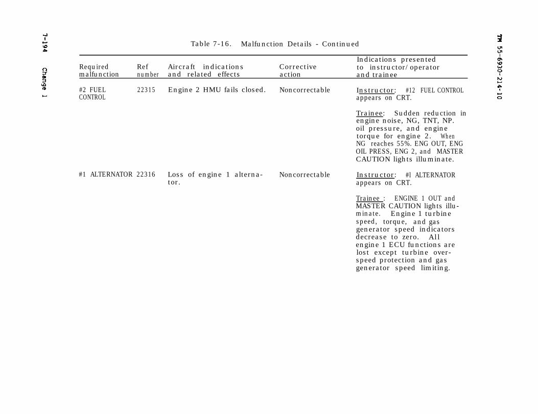
7-194
TM 55-6930-214-10
Change 1
Table 7-16. Malfunction Details - Continued
Indications presentedRequired Ref Aircraft indications Corrective to instructor/operatormalfunction number and related effects action and trainee
#2 FUEL 22315 Engine 2 HMU fails closed. Noncorrectable Instructor: #12 FUEL CONTROLCONTROL appears on CRT.
#1 ALTERNATOR 22316 Loss of engine 1 alterna- Noncorrectabletor.
Trainee: Sudden reduction inengine noise, NG, TNT, NP.oil pressure, and enginetorque for engine 2. WhenNG reaches 55%. ENG OUT, ENGOIL PRESS, ENG 2, and MASTERCAUTION lights illuminate.
Instructor: #l ALTERNATORappears on CRT.
Trainee : ENGINE 1 OUT andMASTER CAUTION lights illu-minate. Engine 1 turbinespeed, torque, and gasgenerator speed indicatorsdecrease to zero. Al lengine 1 ECU functions arelost except turbine over-speed protection and gasgenerator speed limiting.
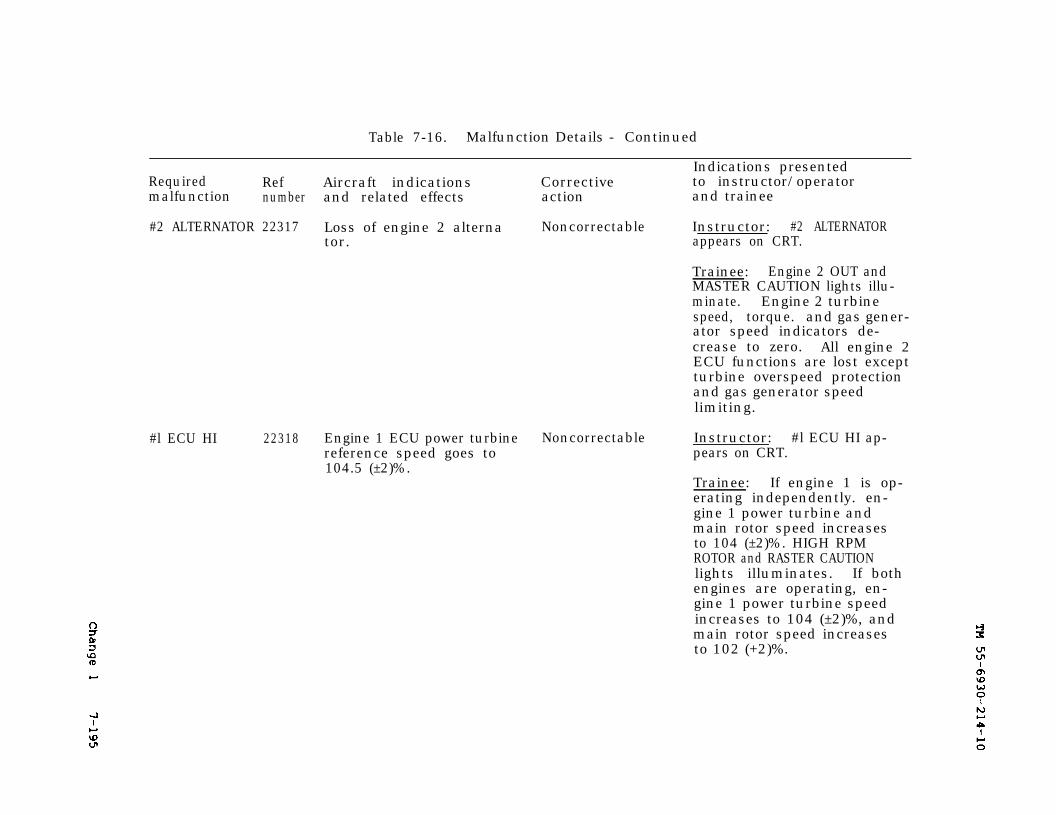
Change 1
TM 55-6930-214-10
7-195
Table 7-16. Malfunction Details - Continued
Indications presentedRequired Ref Aircraft indications Corrective to instructor/operatormalfunction number and related effects action and trainee
#2 ALTERNATOR 22317 Loss of engine 2 alterna Noncorrectable Instructor: #2 ALTERNATORtor. appears on CRT.
Trainee: Engine 2 OUT andMASTER CAUTION lights illu-minate. Engine 2 turbinespeed, torque. and gas gener-ator speed indicators de-crease to zero. All engine 2ECU functions are lost exceptturbine overspeed protectionand gas generator speedlimiting.
#l ECU HI 22318 Engine 1 ECU power turbine Noncorrectable Instructor: #l ECU HI ap-reference speed goes to pears on CRT.104.5 (±2)%.
Trainee: If engine 1 is op-erating independently. en-gine 1 power turbine andmain rotor speed increasesto 104 (±2)%. HIGH RPMROTOR and RASTER CAUTIONlights illuminates. If bothengines are operating, en-gine 1 power turbine speedincreases to 104 (±2)%, andmain rotor speed increasesto 102 (+2)%.
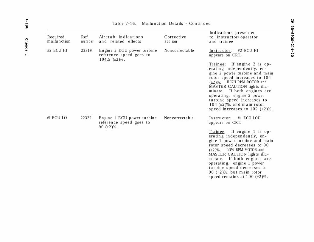
7-196
TM 55-6930-214-10
Change 1
Table 7-16. Malfunction Details - Continued
Indications presentedRef Aircraft indications CorrectiveRequired to instructor/operator
malfunction number and related effects act ion and trainee
#2 ECU HI 22319 Engine 2 ECU power turbine Noncorrectable Instructor: #2 ECU HIreference speed goes to104.5 (±2)%.
appears on CRT.
Trainee: If engine 2 is op-erating independently. en-gine 2 power turbine and mainrotor speed increases to 104(±2)%. HIGH RPM ROTOR andMASTER CAUTION lights illu-minate. If both engines areoperating, engine 2 powerturbine speed increases to104 (±2)%. and main rotorspeed increases to 102 (+2)%.
#l ECU LO 22320 Engine 1 ECU power turbine Noncorrectablereference speed goes to90 (+2)%.
Instructor: #1 ECU LOUappears on CRT.
Trainee: If engine 1 is op-erating independently, en-gine 1 power turbine and mainrotor speed decreases to 90(±2)%. LOW RPM MOTOR andMASTER CAUTION lights illu-minate. If both engines areoperating. engine 1 powerturbine speed decreases to90 (+2)%, but main rotorspeed remains at 100 (±2)%.
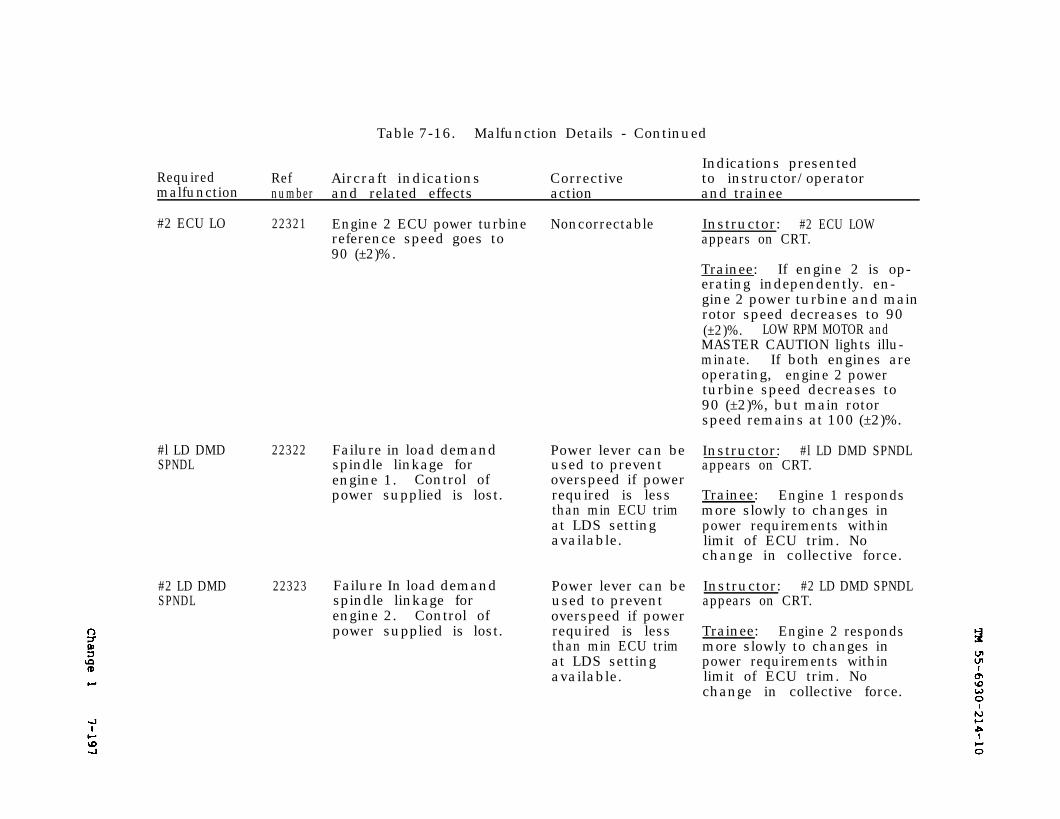
Change 1
TM 55-9930-214-10
7-197
Table 7-16. Malfunction Details - Continued
Indications presentedRequired Ref Aircraft indications Corrective to instructor/operatormalfunction number and related effects action and trainee
#2 ECU LO 22321 Engine 2 ECU power turbine Noncorrectablereference speed goes to90 (±2)%.
#l LD DMDSPNDL
22322 Failure in load demandspindle linkage forengine 1. Control ofpower supplied is lost.
#2 LD DMDSPNDL
22323 Failure In load demandspindle linkage forengine 2. Control ofpower supplied is lost.
Power lever can beused to preventoverspeed if powerrequired is lessthan min ECU trimat LDS settingavailable.
Power lever can beused to preventoverspeed if powerrequired is lessthan min ECU trimat LDS settingavailable.
Instructor: #2 ECU LOWappears on CRT.
Trainee: If engine 2 is op-erating independently. en-gine 2 power turbine and mainrotor speed decreases to 90(±2)%. LOW RPM MOTOR andMASTER CAUTION lights illu-minate. If both engines areoperating, engine 2 powerturbine speed decreases to90 (±2)%, but main rotorspeed remains at 100 (±2)%.
Instructor: #l LD DMD SPNDLappears on CRT.
Trainee: Engine 1 respondsmore slowly to changes inpower requirements withinlimit of ECU trim. Nochange in collective force.
Instructor: #2 LD DMD SPNDLappears on CRT.
Trainee: Engine 2 respondsmore slowly to changes inpower requirements withinlimit of ECU trim. Nochange in collective force.
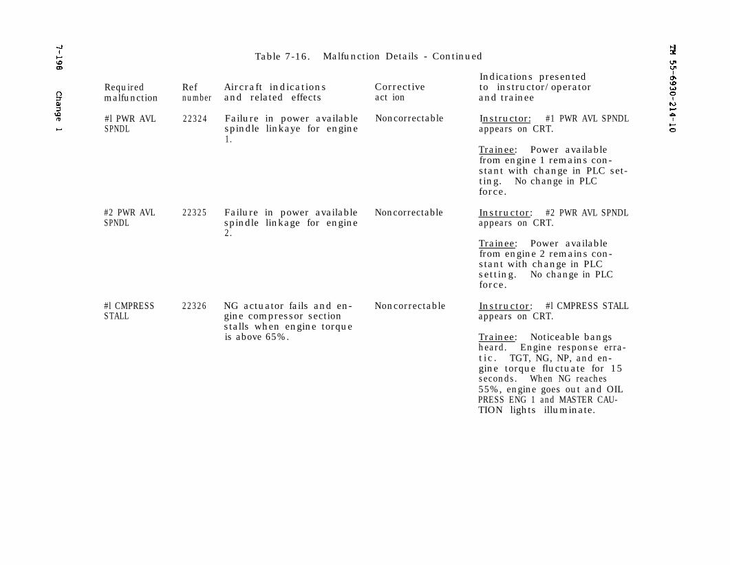
7-198
Change 1
TM 55-6930-214-10
Table 7-16. Malfunction Details - Continued
Indications presentedRequired Ref Aircraft indications Corrective to instructor/operatormalfunction number and related effects act ion and trainee
#l PWR AVL 22324 Failure in power available Noncorrectable Instructor: #1 PWR AVL SPNDLSPNDL spindle linkaye for engine appears on CRT.
1.Trainee: Power availablefrom engine 1 remains con-stant with change in PLC set-ting. No change in PLCforce.
#2 PWR AVLSPNDL
22325 Failure in power available Noncorrectablespindle linkage for engine2.
#l CMPRESSSTALL
22326 NG actuator fails and en- Noncorrectablegine compressor sectionstalls when engine torqueis above 65%.
Instructor: #2 PWR AVL SPNDLappears on CRT.
Trainee: Power availablefrom engine 2 remains con-stant with change in PLCsetting. No change in PLCforce.
Instructor: #l CMPRESS STALLappears on CRT.
Trainee: Noticeable bangsheard. Engine response erra-tic. TGT, NG, NP, and en-gine torque fluctuate for 15seconds. When NG reaches55%, engine goes out and OILPRESS ENG 1 and MASTER CAU-TION lights illuminate.
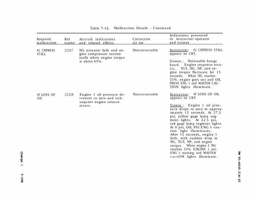
Change 1
TM 55-6930-214-10
7-199
Table 7-16. Malfunction Details - Continued
Indications presentedRequired Ref Aircraft indications Corrective to instructor/operatormalfunction number and related effects act ion and trainee
#2 CMPRESSSTALL
22327 NG actuator fails and en- Noncorrectable Instructor: #2 CHPRESS STALLgine compressor section appears on CRT.stalls when engine torqueis above 65%. Trainee :- - Noticeable bangs
heard. Engine response erra-tic. TGT, NG, NP, and en-gine torque fluctuate for 15seconds. When NG reaches55%. engine goes out and OILPRESS ENG 1 and MASTER CAU-TION lights illuminate.
#l LOSS OFOIL
22328 Engine 1 oil pressure de- Noncorrectablecreases to zero and sub-sequent engine seizureoccurs.
Instructor: #l LOSS OF OILappears on CRT.
Trainee : Engine 1 oil pres-sure drops to zero in approx-imately 15 seconds. At 27.5psi, yellow gage lamp seg-ment lights. At 22.5 psi,red gage lamp segment lights.At 0 psi, OIL PSI ENG 1 cau-tion light illuminates.After 15 seconds, engine 1fails, with sudden drop inNG, TGT, NP, and enginetorque. When engine 1 NGreaches 55%. ENGINE 1 out.ENG 1 warning, and MASTERCAUTION lights illuminate.
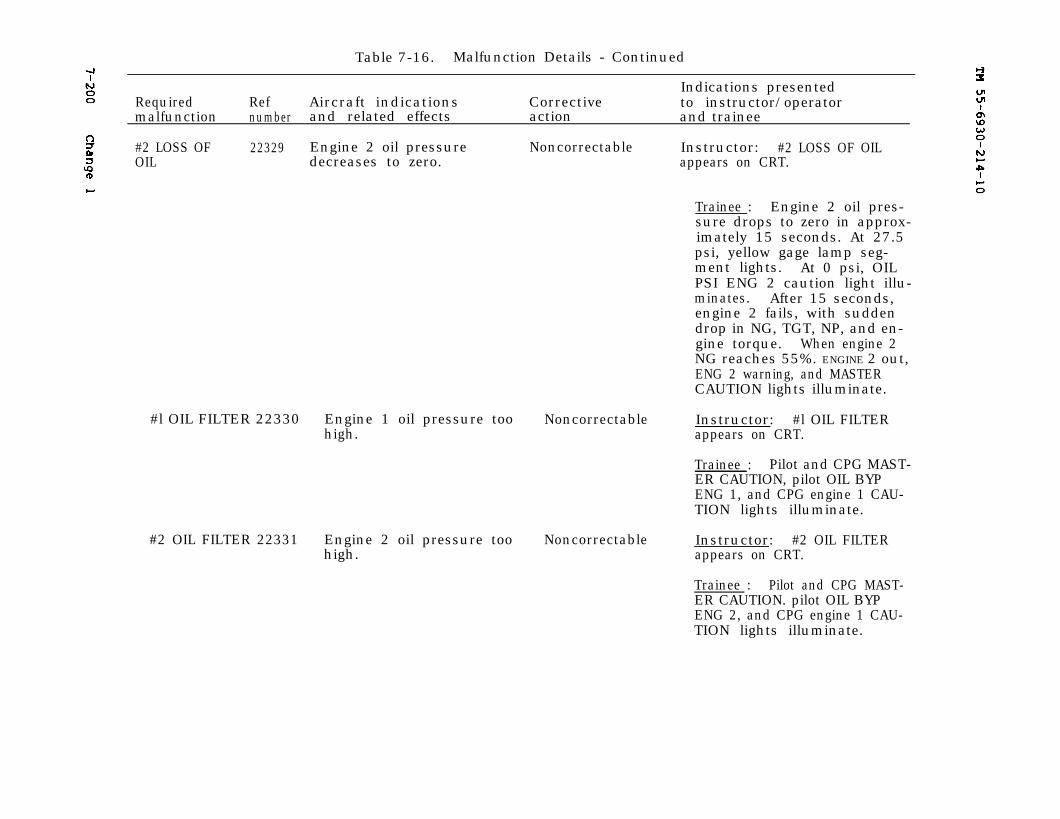
7-200
Change 1
7-200
TM 55-6930-214-10
Table 7-16. Malfunction Details - Continued
Indications presentedRequired Ref Aircraft indications Corrective to instructor/operatormalfunction number and related effects action and trainee
#2 LOSS OF 22329 Engine 2 oil pressure Noncorrectable Instructor: #2 LOSS OF OILOIL decreases to zero. appears on CRT.
Trainee : Engine 2 oil pres-sure drops to zero in approx-imately 15 seconds. At 27.5psi, yellow gage lamp seg-ment lights. At 0 psi, OILPSI ENG 2 caution light illu-minates. After 15 seconds,engine 2 fails, with suddendrop in NG, TGT, NP, and en-gine torque. When engine 2NG reaches 55%. ENGINE 2 out,ENG 2 warning, and MASTERCAUTION lights illuminate.
#l OIL FILTER 22330 Engine 1 oil pressure too Noncorrectablehigh.
Instructor: #l OIL FILTERappears on CRT.
Trainee : Pilot and CPG MAST-ER CAUTION, pilot OIL BYPENG 1, and CPG engine 1 CAU-TION lights illuminate.
#2 OIL FILTER 22331 Engine 2 oil pressure too Noncorrectable Instructor: #2 OIL FILTERhigh. appears on CRT.
Trainee : Pilot and CPG MAST-ER CAUTION. pilot OIL BYPENG 2, and CPG engine 1 CAU-TION lights illuminate.
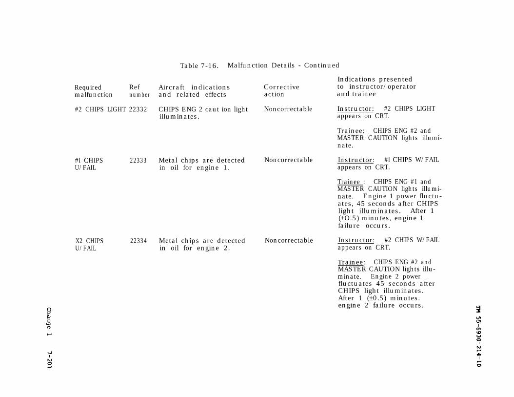
TM 55-6930-214-10
Change 1
7-201
Table 7-16. Malfunction Details - Continued
Indications presentedRequired Ref Aircraft indications Corrective to instructor/operatormalfunction number and related effects action and trainee
#2 CHIPS LIGHT 22332 CHIPS ENG 2 caut ion light Noncorrectable Instructor: #2 CHIPS LIGHTilluminates. appears on CRT.
Trainee: CHIPS ENG #2 andMASTER CAUTION lights illumi-nate.
#l CHIPS 22333 Metal chips are detected Noncorrectable Instructor: #l CHIPS W/FAILU/FAIL in oil for engine 1. appears on CRT.
Trainee : CHIPS ENG #1 andMASTER CAUTION lights illumi-nate. Engine 1 power fluctu-ates, 45 seconds after CHIPSlight illuminates. After 1(±O.5) minutes, engine 1failure occurs.
X2 CHIPSU/FAIL
22334 Metal chips are detected Noncorrectable Instructor: #2 CHIPS W/FAILin oil for engine 2. appears on CRT.
Trainee: CHIPS ENG #2 andMASTER CAUTION lights illu-minate. Engine 2 powerfluctuates 45 seconds afterCHIPS light illuminates.After 1 (±0.5) minutes.engine 2 failure occurs.
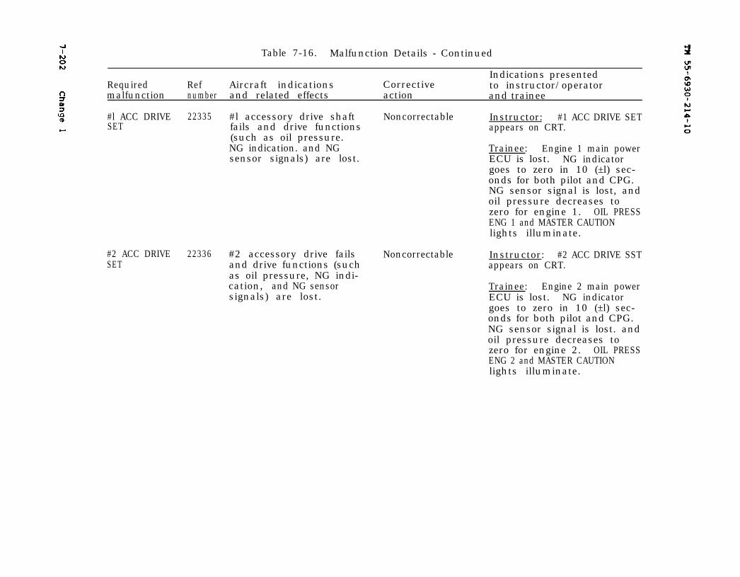
TM 55-6930-214-10
Change 1
7-202Table 7-16. Malfunction Details - Continued
RequiredIndications presented
Ref Aircraft indications Correctivemalfunction
to instructor/operatornumber and related effects action and trainee
#l ACC DRIVE 22335 #l accessory drive shaft Noncorrectable Instructor: #1 ACC DRIVE SETSET fails and drive functions appears on CRT.
(such as oil pressure.NG indication. and NG Trainee: Engine 1 main powersensor signals) are lost. ECU is lost. NG indicator
goes to zero in 10 (±l) sec-onds for both pilot and CPG.NG sensor signal is lost, andoil pressure decreases tozero for engine 1. OIL PRESSENG 1 and MASTER CAUTIONlights illuminate.
#2 ACC DRIVE 22336 #2 accessory drive fails NoncorrectableSET and drive functions (such
as oil pressure, NG indi-cation, and NG sensorsignals) are lost.
Instructor: #2 ACC DRIVE SSTappears on CRT.
Trainee: Engine 2 main powerECU is lost. NG indicatorgoes to zero in 10 (±l) sec-onds for both pilot and CPG.NG sensor signal is lost. andoil pressure decreases tozero for engine 2. OIL PRESSENG 2 and MASTER CAUTIONlights illuminate.
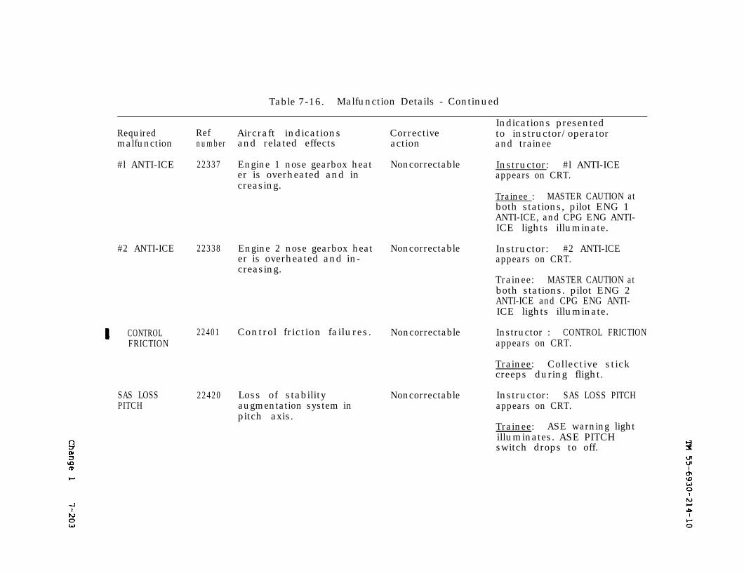
Change 1
TM 55--6930-214-10
7-203
Table 7-16. Malfunction Details - Continued
Required Ref Aircraft indicationsmalfunction number and related effects
#l ANTI-ICE 22337
#2 ANTI-ICE
CONTROLFRICTION
SAS LOSSPITCH
22338
22401
22420
Engine 1 nose gearbox heater is overheated and increasing.
Engine 2 nose gearbox heater is overheated and in-creasing.
Control friction failures.
Loss of stabilityaugmentation system inpitch axis.
Correctiveaction
Indications presentedto instructor/operatorand trainee
Noncorrectable Instructor: #l ANTI-ICEappears on CRT.
Trainee : MASTER CAUTION atboth stations, pilot ENG 1ANTI-ICE, and CPG ENG ANTI-ICE lights illuminate.
Noncorrectable Instructor: #2 ANTI-ICEappears on CRT.
Trainee: MASTER CAUTION atboth stations. pilot ENG 2ANTI-ICE and CPG ENG ANTI-ICE lights illuminate.
Noncorrectable Instructor : CONTROL FRICTIONappears on CRT.
Trainee: Collective stickcreeps during flight.
Noncorrectable Instructor: SAS LOSS PITCHappears on CRT.
Trainee: ASE warning lightilluminates. ASE PITCHswitch drops to off.
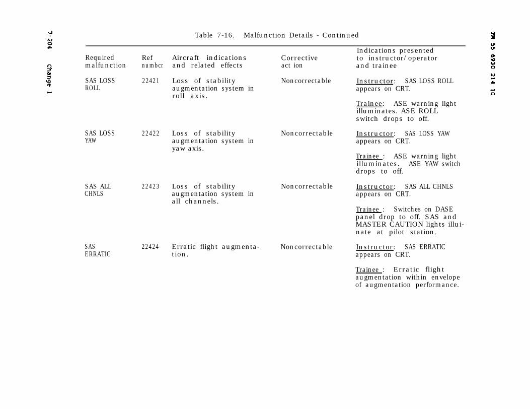
Change 1
TM 55-6930-214-10
7-204Table 7-16. Malfunction Details - Continued
Indications presentedRequired Ref Aircraft indications Corrective to instructor/operatormalfunction numbcr and related effects act ion and trainee
SAS LOSSROLL
SAS LOSSYAW
SAS ALLCHNLS
SASERRATIC
22421
22422
22423
22424
Loss of stabilityaugmentation system inroll axis.
Loss of stabilityaugmentation system inyaw axis.
Loss of stabilityaugmentation system inall channels.
Erratic flight augmenta-tion.
Noncorrectable Instructor: SAS LOSS ROLLappears on CRT.
Trainee: ASE warning lightilluminates. ASE ROLLswitch drops to off.
Noncorrectable Instructor: SAS LOSS YAWappears on CRT.
Trainee : ASE warning lightilluminates. ASE YAW switchdrops to off.
Noncorrectable Instructor: SAS ALL CHNLSappears on CRT.
Trainee : Switches on DASEpanel drop to off. SAS andMASTER CAUTION lights illui-nate at pilot station.
Noncorrectable Instructor: SAS ERRATICappears on CRT.
Trainee : Erratic flightaugmentation within envelopeof augmentation performance.
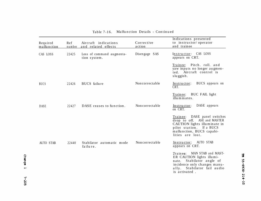
Change 1
TM 55-6930-214-10
7-205
Table 7-16. Malfunction Details - Continued
lndications presentedRequired Ref Aircraft indications Corrective to instructor/operatormalfunction number and related effects action and trainee
CAS LOSS 22425 Loss of command augmenta- Disengage SAS Instructor: CAS LOSStion system. appears on CRT.
Trainee: Pitch. roll. andyaw inputs no longer augmen-ted. Aircraft control issluggish.
BUCS
DASE
22426 BUCS failure Noncorrectable
22427 DASE ceases to function. Noncorrectable
AUTO STAB 22440 Stabilator automatic mode Noncorrectable Instructor: AUTO STABfailure. appears on CRT.
Instructor: BUCS appears onCRT.
Trainee: BUC FAIL lightilluminates.
Instructor: DASE appearson CRT.
Trainee: DASE panel switchesdrop to off. ASE and MASTERCAUTION lights illuminate inpilot station. If a BUCSmalfunction, BUCS capabi-lities are lost.
Trainee: MAN STAB and MAST-- ~ER CAUTION lights illumi-nate. Stabilator angle ofincidence only changes manu-ally. Stabilator fail audiois activated .
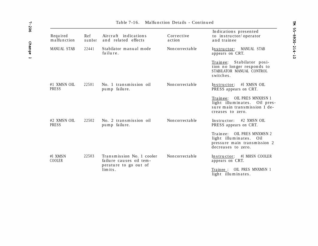
7-206
Change 1
TM 55-6930-214-10
Table 7-16. Malfunction Details - Continued
Indications presentedRequired Ref Aircraft indications to instructor/operatorCorrectivemalfunction number and related effects action and trainee
MANUAL STAB 22441
#1 XMSN OILPRESS
#2 XMSN OILPRESS
#l XMSNCOOLER
22501
22502
22503
Stabilator manual modefailure.
No. 1 transmission oilpump failure.
No. 2 transmission oilpump failure.
Transmission No. 1 coolerfailure causes oil tem-perature to go out oflimits.
Noncorrectable Instructor: MANUAL STABappears on CRT.
Trainee: Stabilator posi-tion no longer responds toSTABILATOR MANUAL CONTROLswitches.
Noncorrectable Instructor: #l XMSN OILPRESS appears on CRT.
Trainee: OIL PRES MNXHSN 1light illuminates. Oil pres-sure main transmission 1 de-creases to zero.
Noncorrectable Instructor: #2 XMSN OILPRESS appears on CRT.
Trainee: OIL PRES MNXMSN 2light illuminates. Oilpressure main transmission 2decreases to zero.
Noncorrectable Instructor: #l MHSN COOLERappears on CRT.
Trainee : OIL PRES MNXMSN 1light illuminates.
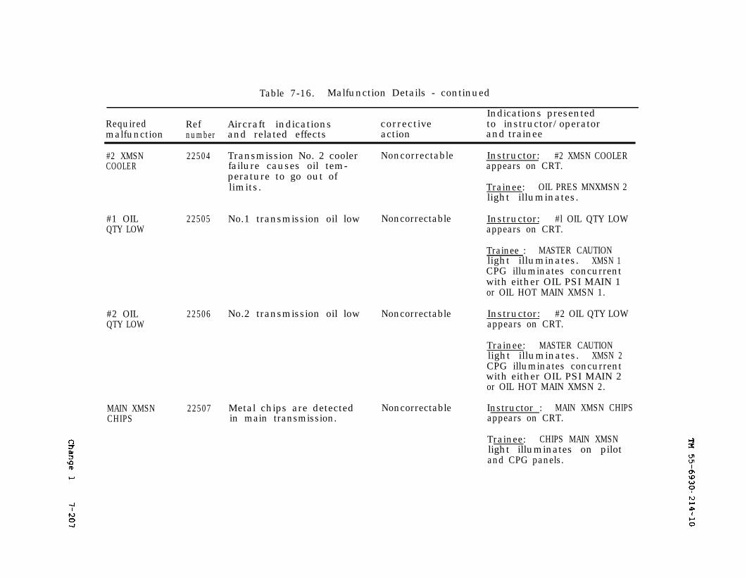
7-207
Change 1
TM 55-6930-214-10
Table 7-16. Malfunction Details - continued
Required Ref Aircraft indicationsmalfunction number and related effects
#2 XMSN 22504COOLER
#1 OILQTY LOW
#2 OILQTY LOW
22505
22506
MAIN XMSNCHIPS
22507
Transmission No. 2 coolerfailure causes oil tem-perature to go out oflimits.
correctiveaction
Noncorrectable
No.1 transmission oil low Noncorrectable
No.2 transmission oil low
Metal chips are detectedin main transmission.
Indications presentedto instructor/operatorand trainee
Instructor: #2 XMSN COOLERappears on CRT.
Trainee: OIL PRES MNXMSN 2light illuminates.
Instructor: #l OIL QTY LOWappears on CRT.
Trainee : MASTER CAUTIONlight illuminates. XMSN 1CPG illuminates concurrentwith either OIL PSI MAIN 1or OIL HOT MAIN XMSN 1.
Noncorrectable Instructor: #2 OIL QTY LOWappears on CRT.
Trainee: MASTER CAUTIONlight illuminates. XMSN 2CPG illuminates concurrentwith either OIL PSI MAIN 2or OIL HOT MAIN XMSN 2.
Noncorrectable Instructor : MAIN XMSN CHIPSappears on CRT.
Trainee: CHIPS MAIN XMSNlight illuminates on pilotand CPG panels.
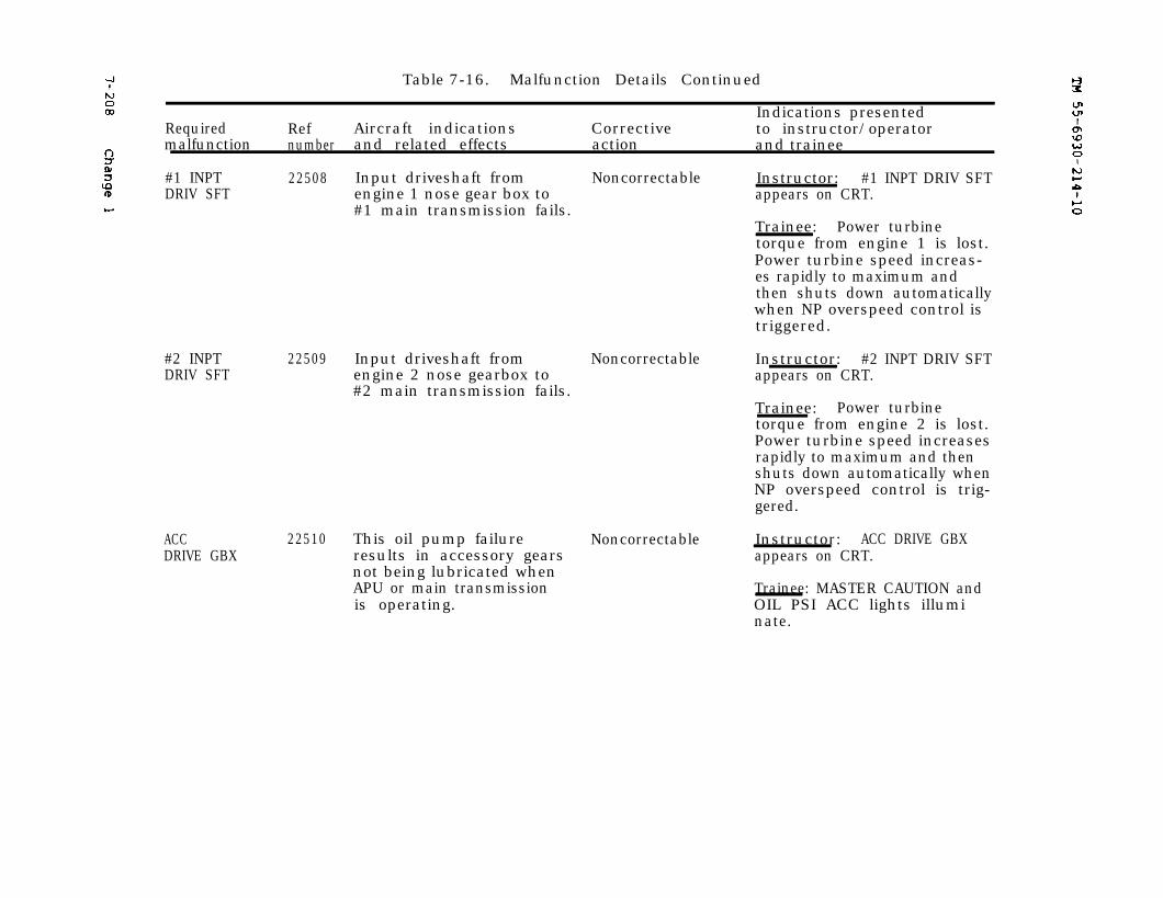
7-208
Change 1
TM 55-6930-214-10
Table 7-16. Malfunction Details Continued
Indications presentedRequired Ref Aircraft indications Corrective to instructor/operatormalfunction number and related effects action and trainee
#1 INPTDRIV SFT
22508 Input driveshaft from Noncorrectable Instructor: #1 INPT DRIV SFTengine 1 nose gear box to appears on CRT.#1 main transmission fails.
Trainee: Power turbinetorque from engine 1 is lost.Power turbine speed increas-es rapidly to maximum andthen shuts down automaticallywhen NP overspeed control istriggered.
#2 INPTDRIV SFT
22509 Input driveshaft from Noncorrectable Instructor: #2 INPT DRIV SFTengine 2 nose gearbox to appears on CRT.#2 main transmission fails.
Trainee: Power turbinetorque from engine 2 is lost.Power turbine speed increasesrapidly to maximum and thenshuts down automatically whenNP overspeed control is trig-gered.
ACCDRIVE GBX
22510 This oil pump failure Noncorrectable Instructor: ACC DRIVE GBXresults in accessory gears appears on CRT.not being lubricated whenAPU or main transmission Trainee: MASTER CAUTION andis operating. OIL PSI ACC lights illumi
nate.
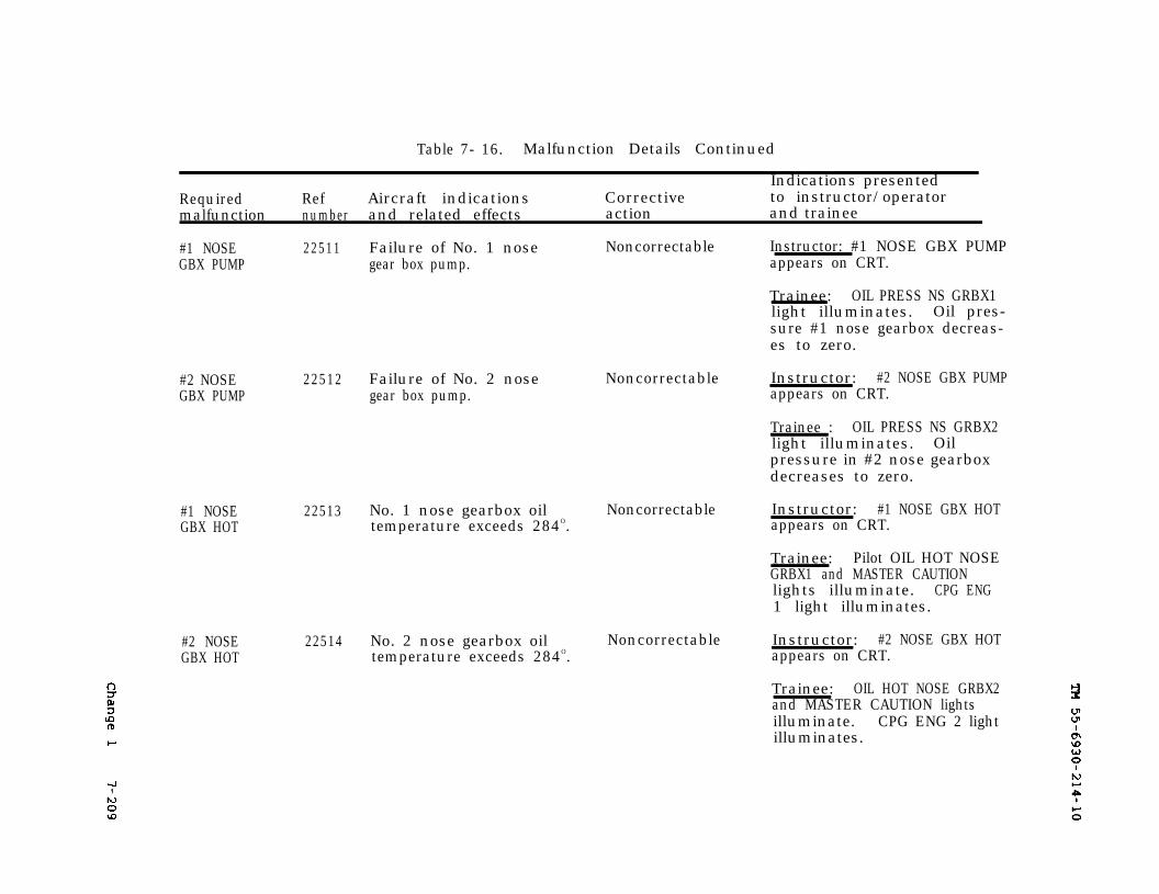
Change 1
TM 55-6930-214-10
7-209
Table 7- 16. Malfunction Details Continued
Indications presentedRequired Ref Aircraft indications Corrective to instructor/operatormalfunction number and related effects action and trainee
#1 NOSE 22511 Failure of No. 1 nose Noncorrectable Instructor: #1 NOSE GBX PUMPGBX PUMP gear box pump. appears on CRT.
Trainee: OIL PRESS NS GRBX1light illuminates. Oil pres-sure #1 nose gearbox decreas-es to zero.
#2 NOSEGBX PUMP
22512 Failure of No. 2 nosegear box pump.
Noncorrectable Instructor: #2 NOSE GBX PUMPappears on CRT.
Trainee : OIL PRESS NS GRBX2light illuminates. Oilpressure in #2 nose gearboxdecreases to zero.
#1 NOSEGBX HOT
22513 No. 1 nose gearbox oil Noncorrectable Instructor: #1 NOSE GBX HOTtemperature exceeds 284O. appears on CRT.
Trainee: Pilot OIL HOT NOSEGRBX1 and MASTER CAUTIONlights illuminate. CPG ENG1 light illuminates.
#2 NOSEGBX HOT
22514 No. 2 nose gearbox oil Noncorrectable Instructor: #2 NOSE GBX HOTtemperature exceeds 284O. appears on CRT.
Trainee: OIL HOT NOSE GRBX2and MASTER CAUTION lightsilluminate. CPG ENG 2 lightilluminates.
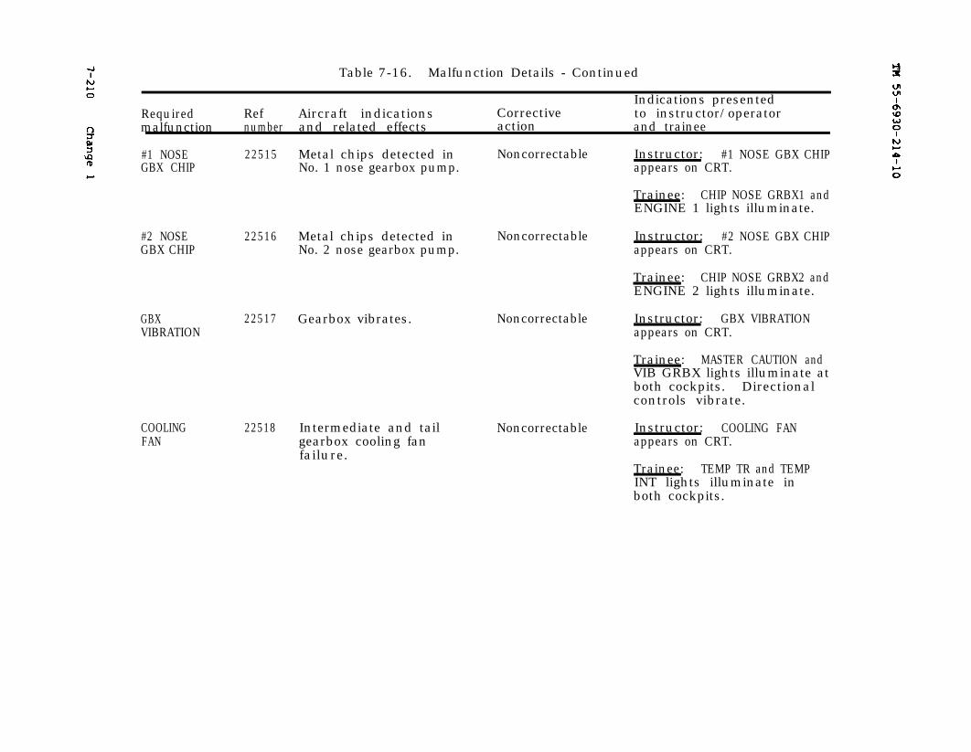
7-210 Change 1 TM 55-6930-214-10
Table 7-16. Malfunction Details - Continued
Indications presentedRequired Ref Aircraft indications Corrective to instructor/operatormalfunction number and related effects action and trainee
#1 NOSE 22515GBX CHIP
#2 NOSEGBX CHIP
22516
GBXVIBRATION
22517 Gearbox vibrates. Noncorrectable
COOLINGFAN
Metal chips detected in Noncorrectable Instructor: #1 NOSE GBX CHIPNo. 1 nose gearbox pump. appears on CRT.
Trainee: CHIP NOSE GRBX1 andENGINE 1 lights illuminate.
Metal chips detected in Noncorrectable Instructor: #2 NOSE GBX CHIPNo. 2 nose gearbox pump. appears on CRT.
Trainee: CHIP NOSE GRBX2 andENGINE 2 lights illuminate.
Instructor: GBX VIBRATIONappears on CRT.
Trainee: MASTER CAUTION andVIB GRBX lights illuminate atboth cockpits. Directionalcontrols vibrate.
22518 Intermediate and tailgearbox cooling fanfailure.
Noncorrectable Instructor: COOLING FANappears on CRT.
Trainee: TEMP TR and TEMPINT lights illuminate inboth cockpits.
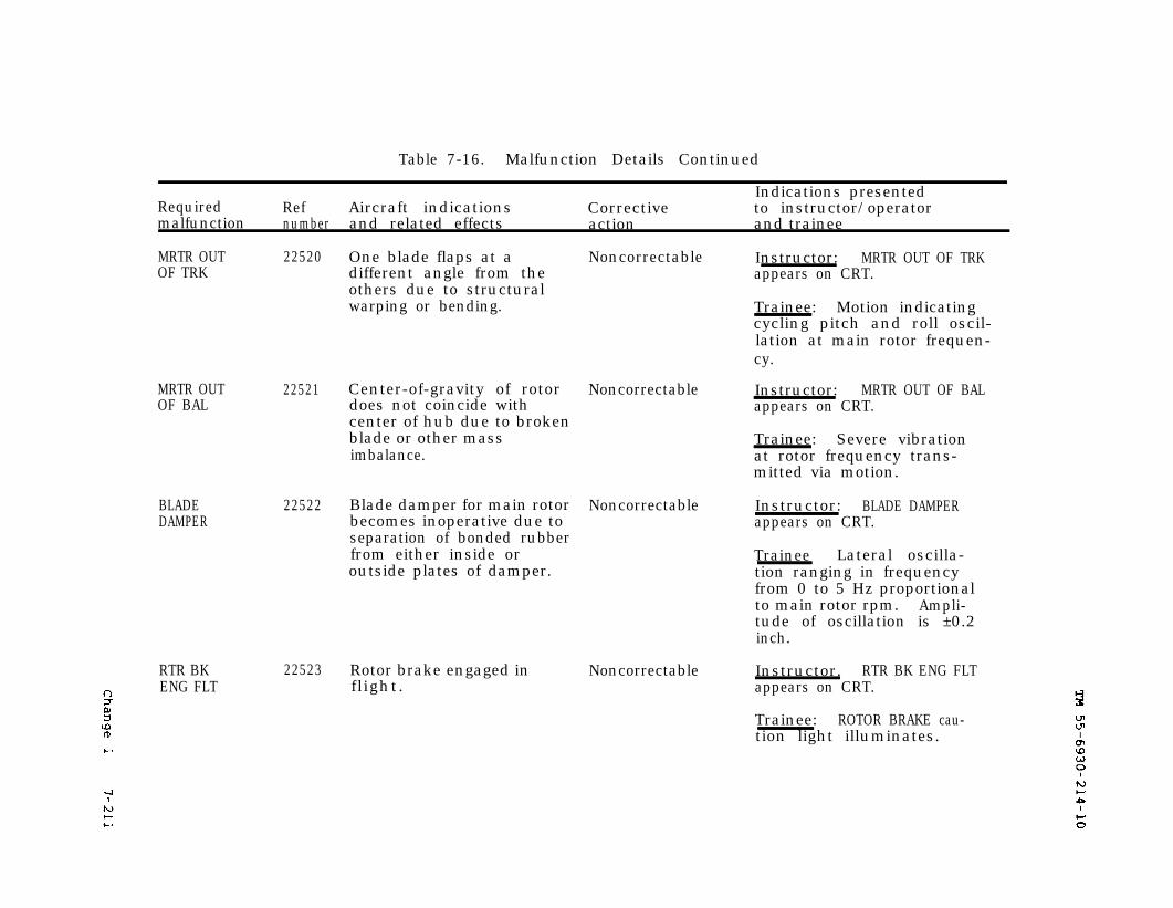
TM 55-6930-214-10
Change 1
7-211
Table 7-16. Malfunction Details Continued
Indications presentedRequired Ref Aircraft indications Corrective to instructor/operatormalfunction number and related effects action and trainee
MRTR OUT 22520OF TRK
MRTR OUTOF BAL
BLADEDAMPER
RTR BKENG FLT
22521
22522
One blade flaps at a Noncorrectabledifferent angle from theothers due to structuralwarping or bending.
Center-of-gravity of rotor Noncorrectabledoes not coincide withcenter of hub due to brokenblade or other massimbalance.
Blade damper for main rotor Noncorrectablebecomes inoperative due toseparation of bonded rubberfrom either inside oroutside plates of damper.
22523 Rotor brake engaged inflight.
Noncorrectable
Instructor: MRTR OUT OF TRKappears on CRT.
Trainee: Motion indicatingcycling pitch and roll oscil-lation at main rotor frequen-cy.
Instructor: MRTR OUT OF BALappears on CRT.
Trainee: Severe vibrationat rotor frequency trans-mitted via motion.
Instructor: BLADE DAMPERappears on CRT.
Trainee Lateral oscilla-tion ranging in frequencyfrom 0 to 5 Hz proportionalto main rotor rpm. Ampli-tude of oscillation is ±0.2inch.
Instructor. RTR BK ENG FLTappears on CRT.
Trainee: ROTOR BRAKE cau-tion light illuminates.
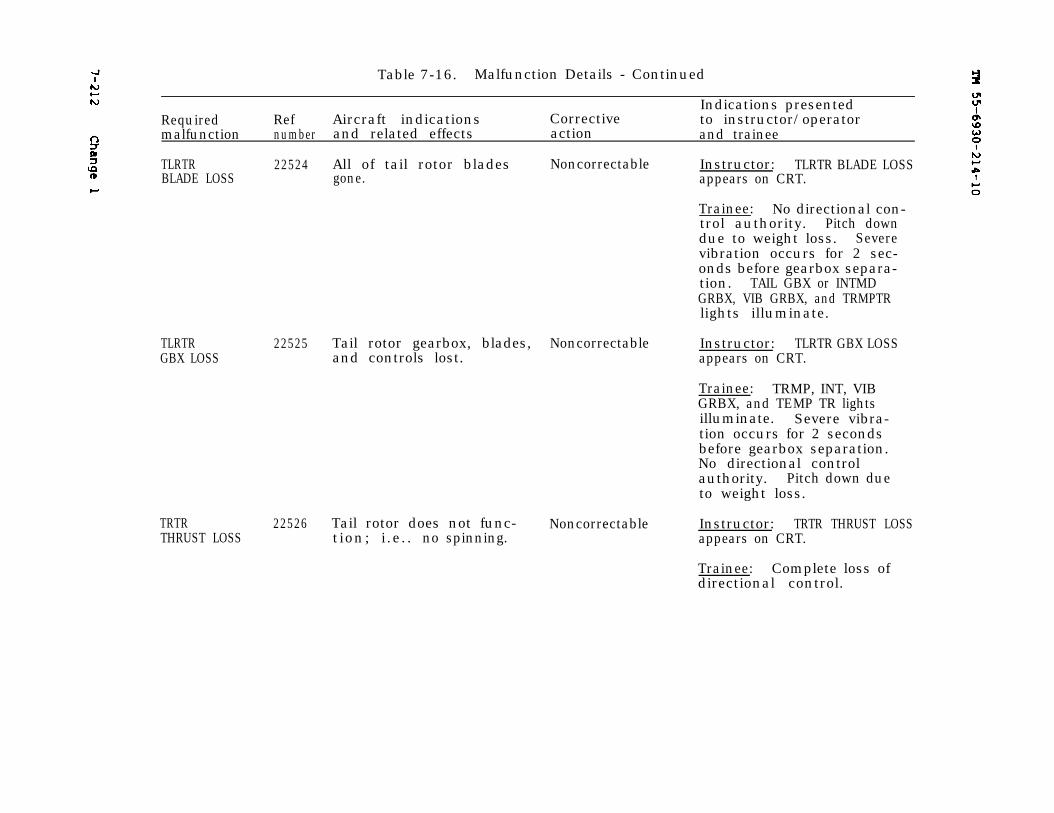
7-212
Change 1
TM 55-6930-214-10Required
Table 7-16. Malfunction Details - Continued
Indications presentedRef Aircraft indications Corrective to instructor/operator
malfunction number and related effects action and trainee
TLRTR 22524 All of tail rotor blades Noncorrectable Instructor: TLRTR BLADE LOSSBLADE LOSS gone. appears on CRT.
Trainee: No directional con-trol authority. Pitch downdue to weight loss. Severevibration occurs for 2 sec-onds before gearbox separa-tion. TAIL GBX or INTMDGRBX, VIB GRBX, and TRMPTRlights illuminate.
TLRTR 22525 Tail rotor gearbox, blades, NoncorrectableGBX LOSS and controls lost.
TRTRTHRUST LOSS
22526 Tail rotor does not func- Noncorrectabletion; i.e.. no spinning.
Instructor: TLRTR GBX LOSSappears on CRT.
Trainee: TRMP, INT, VIBGRBX, and TEMP TR lightsilluminate. Severe vibra-tion occurs for 2 secondsbefore gearbox separation.No directional controlauthority. Pitch down dueto weight loss.
Instructor: TRTR THRUST LOSSappears on CRT.
Trainee: Complete loss ofdirectional control.
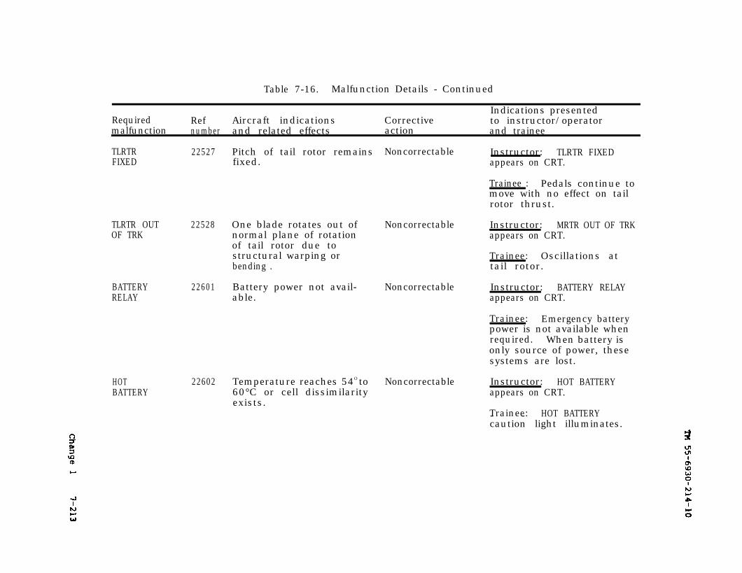
Change 1
TM 55-6930-214-10
7-213
Table 7-16. Malfunction Details - Continued
Indications presentedRequired Ref Aircraft indications Corrective to instructor/operatormalfunction number and related effects action and trainee
TLRTRFIXED
22527 Pitch of tail rotor remains Noncorrectable Instructor: TLRTR FIXEDfixed. appears on CRT.
Trainee : Pedals continue tomove with no effect on tailrotor thrust.
TLRTR OUTOF TRK
22528 One blade rotates out of Noncorrectablenormal plane of rotationof tail rotor due tostructural warping orbending .
BATTERY 22601 Battery power not avail- NoncorrectableRELAY able.
HOTBATTERY
22602 Temperature reaches 54O to Noncorrectable60°C or cell dissimilarityexists.
Instructor: MRTR OUT OF TRKappears on CRT.
Trainee: Oscillations attail rotor.
Instructor: BATTERY RELAYappears on CRT.
Trainee: Emergency batterypower is not available whenrequired. When battery isonly source of power, thesesystems are lost.
Instructor: HOT BATTERYappears on CRT.
Trainee: HOT BATTERY- -caution light illuminates.

7-214
Change 1
TM 55-6930-214-10
Table 7-16. Malfunction Details Continued
Required Refmalfunction number
BATTERY 22603CHARGER
#1 AC 22604 Loss of output from oneGENERATOR generator.
#2 ACGENERATOR
22605
Aircraft indicationsand related effects
Battery charger notfunctional.
Loss of output from onegenerator.
Indications presentedCorrective to instructor/operatoraction and trainee
Noncorrectable Instructor: BATTERY CHARGERappears on CRT.
Trainee: CHARGER and MASTERCAUTION lights illuminate.
Noncorrectable Instructor: #1 AC GENERATORappears on CRT.
Trainee: GEN 1 cautionlight illuminates. (Alsosee #2 AC GENERATOR).
Noncorrectable Instructor: #2 AC GENERATORappears on CRT.
Trainee: GEN 2 cautionlight illuminates. If bothGEN 1 and GEN 2 are failed,MASTER CAUTION lights atboth stations illuminate.Pilot GEN 1. GEN 2, RECT 1,RECT 2, and battery chargercaution lights illuminate.CPG ELEC SYS FAIL lightsilluminate. Generator poweris lost. Battery emergencybus system remains activefor 12 minutes.
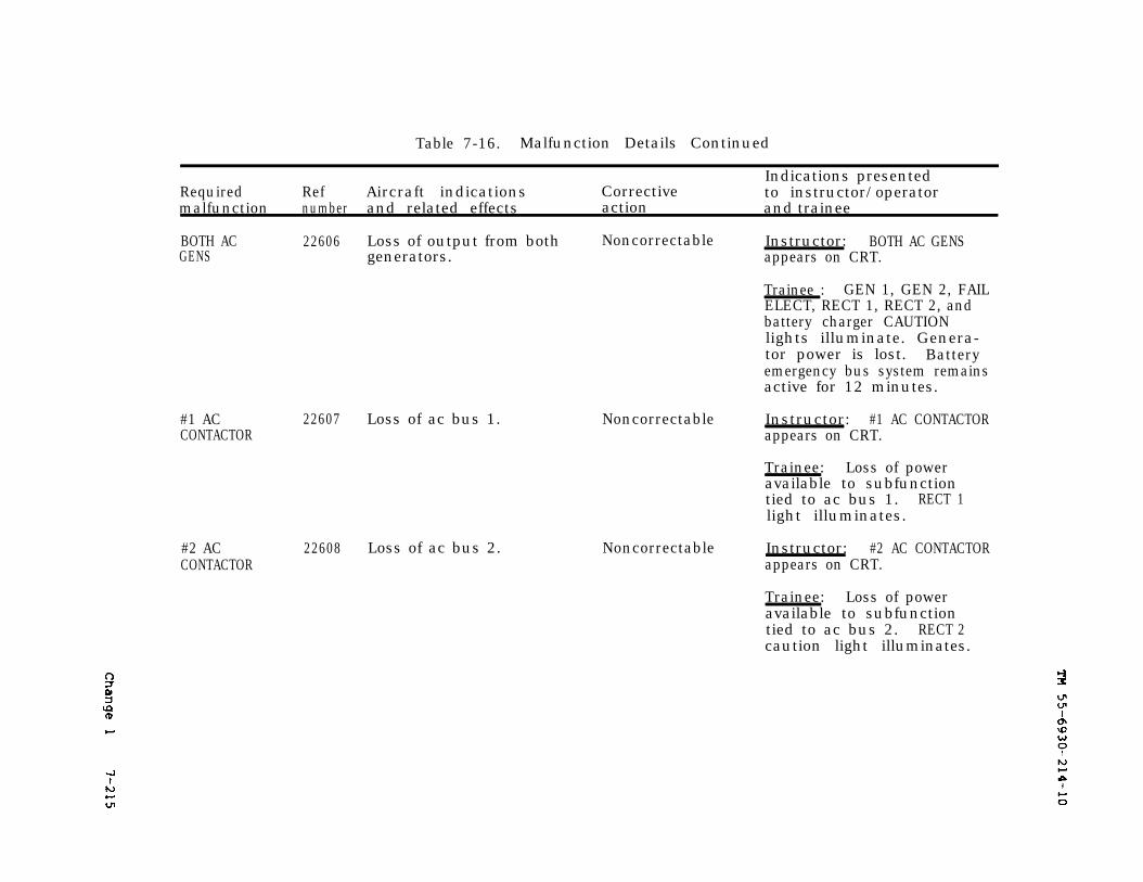
Change 1
TM 55-6930-214-10
7-215
Table 7-16. Malfunction Details Continued
Indications presentedRequired Ref Aircraft indications Corrective to instructor/operatormalfunction number and related effects action and trainee
BOTH AC 22606 Loss of output from both Noncorrectable Instructor: BOTH AC GENSGENS generators. appears on CRT.
Trainee : GEN 1, GEN 2, FAILELECT, RECT 1, RECT 2, andbattery charger CAUTIONlights illuminate. Genera-tor power is lost. Batteryemergency bus system remainsactive for 12 minutes.
#1 ACCONTACTOR
22607 Loss of ac bus 1.
#2 ACCONTACTOR
22608 Loss of ac bus 2.
Noncorrectable Instructor: #1 AC CONTACTORappears on CRT.
Trainee: Loss of poweravailable to subfunctiontied to ac bus 1. RECT 1light illuminates.
Noncorrectable Instructor: #2 AC CONTACTORappears on CRT.
Trainee: Loss of poweravailable to subfunctiontied to ac bus 2. RECT 2caution light illuminates.
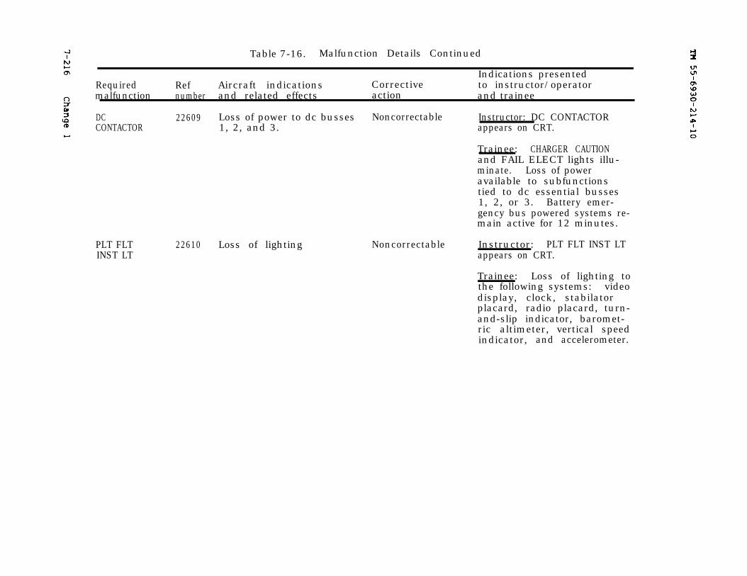
TM 55-6930-214-107-216 Change 1
Table 7-16. Malfunction Details Continued
Indications presentedRequired Ref Aircraft indications Corrective to instructor/operatormalfunction number and related effects action and trainee
DC 22609 Loss of power to dc busses Noncorrectable Instructor: DC CONTACTORCONTACTOR 1, 2, and 3. appears on CRT.
Trainee: CHARGER CAUTIONand FAIL ELECT lights illu-minate. Loss of poweravailable to subfunctionstied to dc essential busses1, 2, or 3. Battery emer-gency bus powered systems re-main active for 12 minutes.
PLT FLTINST LT
22610 Loss of lighting Noncorrectable Instructor: PLT FLT INST LTappears on CRT.
Trainee: Loss of lighting tothe following systems: videodisplay, clock, stabilatorplacard, radio placard, turn-and-slip indicator, baromet-ric altimeter, vertical speedindicator, and accelerometer.
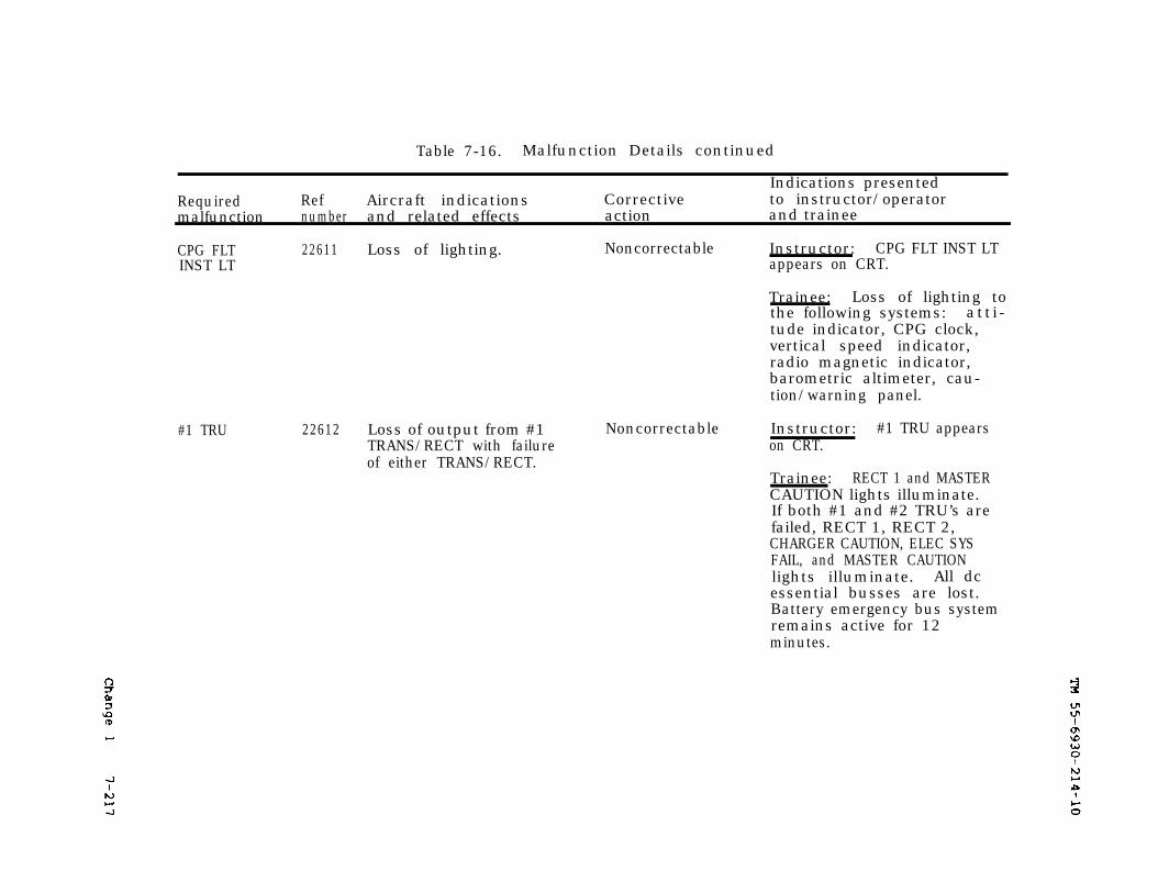
Change 1
TM 55-6930-214-10
7-217
Table 7-16. Malfunction Details continued
Indications presentedRequired Ref Aircraft indications Corrective to instructor/operatormalfunction number and related effects action and trainee
CPG FLT 22611INST LT
#1 TRU 22612
Loss of lighting. Noncorrectable Instructor: CPG FLT INST LTappears on CRT.
Trainee: Loss of lighting tothe following systems: atti-tude indicator, CPG clock,vertical speed indicator,radio magnetic indicator,barometric altimeter, cau-tion/warning panel.
Loss of output from #1TRANS/RECT with failureof either TRANS/RECT.
Noncorrectable Instructor: #1 TRU appearson CRT.
Trainee: RECT 1 and MASTERCAUTION lights illuminate.If both #1 and #2 TRU’s arefailed, RECT 1, RECT 2,CHARGER CAUTION, ELEC SYSFAIL, and MASTER CAUTIONlights illuminate. All dcessential busses are lost.Battery emergency bus systemremains active for 12minutes.
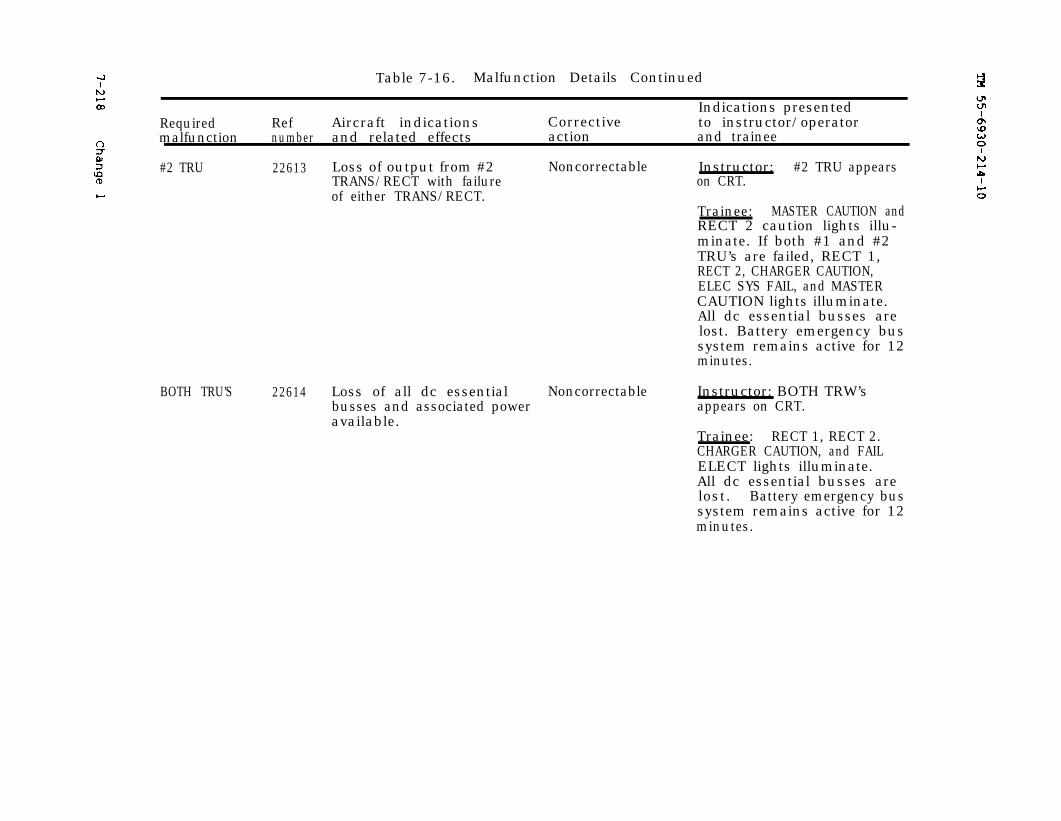
TM 55-6930-214-107-218 Change 1
Table 7-16. Malfunction Details Continued
Indications presentedRequired Ref Aircraft indications Corrective to instructor/operatormalfunction number and related effects action and trainee
#2 TRU 22613 Loss of output from #2 Noncorrectable Instructor: #2 TRU appearsTRANS/RECT with failure on CRT.of either TRANS/RECT.
Trainee: MASTER CAUTION andRECT 2 caution lights illu-minate. If both #1 and #2TRU’s are failed, RECT 1,RECT 2, CHARGER CAUTION,ELEC SYS FAIL, and MASTERCAUTION lights illuminate.All dc essential busses arelost. Battery emergency bussystem remains active for 12minutes.
BOTH TRU’S 22614 Loss of all dc essential Noncorrectablebusses and associated poweravailable.
Instructor: BOTH TRW’sappears on CRT.
Trainee: RECT 1, RECT 2.CHARGER CAUTION, and FAILELECT lights illuminate.All dc essential busses arelost. Battery emergency bussystem remains active for 12minutes.
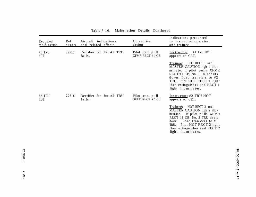
Change 1
TM 55-6930-214-10
7-219
#2 TRUHOT
Table 7-16. Malfunction Details Continued
Indications presentedRequired Ref Aircraft indications Corrective to instructor/operatormalfunction number and related effects action and trainee
#1 TRU 22615 Rectifier fan for #1 TRU Pilot can pull Instructor: #1 TRU HOTHOT fails. XFMR RECT #1 CB. appears on CRT.
Trainee: HOT RECT 1 andMASTER CAUTION lights illu-minate. If pilot pulls XFMRRECT #1 CB, No. 1 TRU shutsdown. Load transfers to #2TRU. Pilot HOT RECT 1 lightthen extinguishes and RECT 1light illuminates.
22616 Rectifier fan for #2 TRU Pilot can pull Instructor: #2 TRU HOTfails. XFER RECT #2 CB. appears on CRT.
Trainee: HOT RECT 2 andMASTER CAUTION lights illu-minate. If pilot pulls XFMRRECT #2 CB, No. 2 TRU shutsdown. Load transfers to #1TRU. Pilot HOT RECT 2 lightthen extinguishes and RECT 2light illuminates.
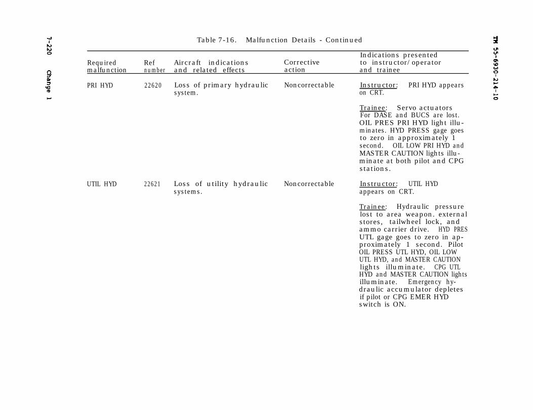
TM 55-6930-214-107-220 Change 1
Table 7-16. Malfunction Details - Continued
Indications presentedRequired Ref Aircraft indications Corrective to instructor/operatormalfunction number and related effects action and trainee
PRI HYD 22620 Loss of primary hydraulic Noncorrectable Instructor: PRI HYD appearssystem. on CRT.
Trainee: Servo actuatorsFor DASE and BUCS are lost.OIL PRES PRI HYD light illu-minates. HYD PRESS gage goesto zero in approximately 1second. OIL LOW PRI HYD andMASTER CAUTION lights illu-minate at both pilot and CPGstations.
UTIL HYD 22621 Loss of utility hydraulic Noncorrectable Instructor: UTIL HYDsystems. appears on CRT.
Trainee: Hydraulic pressurelost to area weapon. externalstores, tailwheel lock, andammo carrier drive. HYD PRESUTL gage goes to zero in ap-proximately 1 second. PilotOIL PRESS UTL HYD, OIL LOWUTL HYD, and MASTER CAUTIONlights illuminate. CPG UTLHYD and MASTER CAUTION lightsilluminate. Emergency hy-draulic accumulator depletesif pilot or CPG EMER HYDswitch is ON.
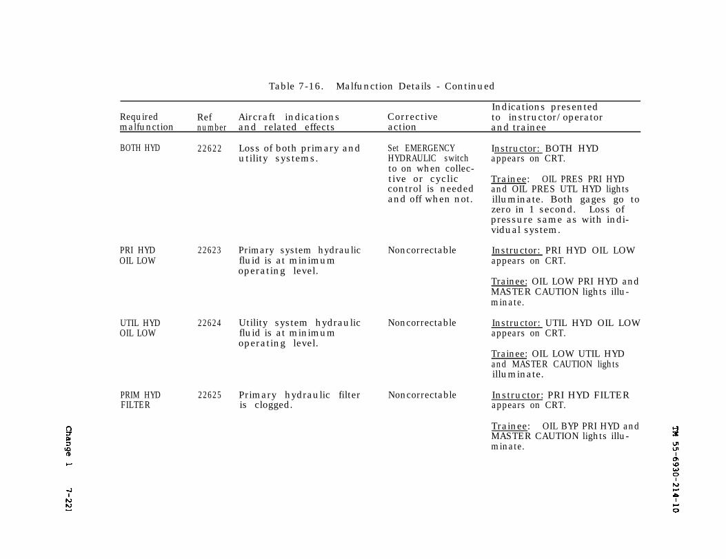
Change 1 7-221 TM 55-6930-214-10
Table 7-16. Malfunction Details - Continued
Indications presentedRequired Ref Aircraft indications Corrective to instructor/operatormalfunction number and related effects action and trainee
BOTH HYD 22622
PRI HYDOIL LOW
UTIL HYDOIL LOW
PRIM HYDFILTER
22623
22624
22625
Loss of both primary andutility systems.
Primary system hydraulicfluid is at minimumoperating level.
Utility system hydraulicfluid is at minimumoperating level.
Primary hydraulic filteris clogged.
Set EMERGENCYHYDRAULIC switchto on when collec-tive or cycliccontrol is neededand off when not.
Noncorrectable
Noncorrectable
Noncorrectable
Instructor: BOTH HYDappears on CRT.
Trainee: OIL PRES PRI HYDand OIL PRES UTL HYD lightsilluminate. Both gages go tozero in 1 second. Loss ofpressure same as with indi-vidual system.
Instructor: PRI HYD OIL LOWappears on CRT.
Trainee: OIL LOW PRI HYD andMASTER CAUTION lights illu-minate.
Instructor: UTIL HYD OIL LOWappears on CRT.
Trainee: OIL LOW UTIL HYDand MASTER CAUTION lightsilluminate.
Instructor: PRI HYD FILTERappears on CRT.
Trainee: OIL BYP PRI HYD andMASTER CAUTION lights illu-minate.
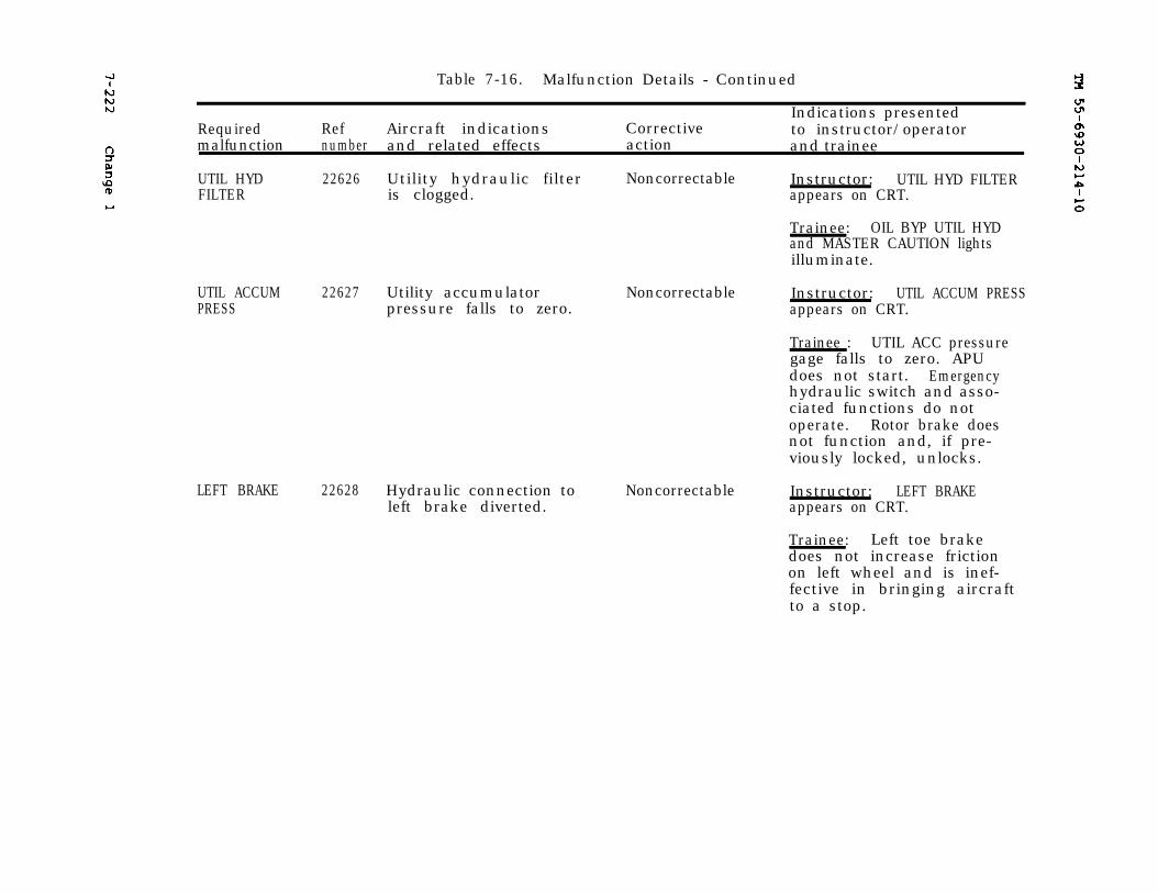
7-222
Change 1
TM 55-6930-214-10
Table 7-16. Malfunction Details - Continued
Indications presentedRequired Ref Aircraft indications Corrective to instructor/operatormalfunction number and related effects action and trainee
UTIL HYD 22626FILTER
UTIL ACCUMPRESS
22627
LEFT BRAKE 22628
Utility hydraulic filter Noncorrectable Instructor: UTIL HYD FILTERis clogged. appears on CRT.
Trainee: OIL BYP UTIL HYDand MASTER CAUTION lightsilluminate.
Utility accumulatorpressure falls to zero.
Noncorrectable Instructor: UTIL ACCUM PRESSappears on CRT.
Trainee : UTIL ACC pressuregage falls to zero. APUdoes not start. Emergencyhydraulic switch and asso-ciated functions do notoperate. Rotor brake doesnot function and, if pre-viously locked, unlocks.
Hydraulic connection toleft brake diverted.
Noncorrectable Instructor: LEFT BRAKEappears on CRT.
Trainee: Left toe brakedoes not increase frictionon left wheel and is inef-fective in bringing aircraftto a stop.
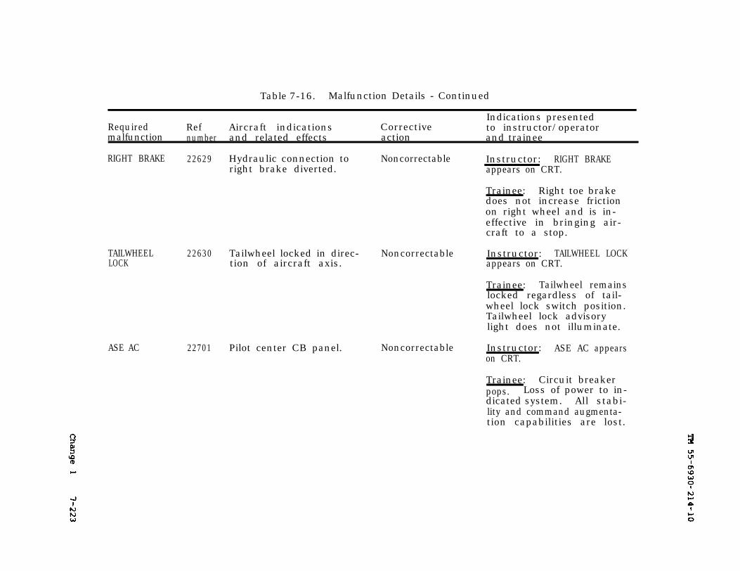
Change 1
TM 55-6930-214-10
7-223
Table 7-16. Malfunction Details - Continued
Indications presentedRequired Ref Aircraft indications Corrective to instructor/operatormalfunction number and related effects action and trainee
RIGHT BRAKE 22629
TAILWHEELLOCK
ASE AC
22630
Hydraulic connection toright brake diverted.
Tailwheel locked in direc-tion of aircraft axis.
22701 Pilot center CB panel.
Noncorrectable Instructor: RIGHT BRAKEappears on CRT.
Trainee: Right toe brakedoes not increase frictionon right wheel and is in-effective in bringing air-craft to a stop.
Noncorrectable Instructor: TAILWHEEL LOCKappears on CRT.
Trainee: Tailwheel remainslocked regardless of tail-wheel lock switch position.Tailwheel lock advisorylight does not illuminate.
Noncorrectable Instructor: ASE AC appearson CRT.
Trainee: Circuit breakerpops. Loss of power to in-dicated system. All stabi-lity and command augmenta-tion capabilities are lost.
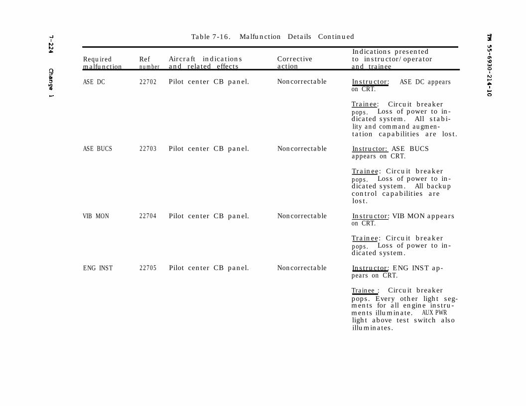
7-224
Change 1
TM 55-6930-214-10
Table 7-16. Malfunction Details Continued
Indications presentedRequired Ref Aircraft indications Corrective to instructor/operatormalfunction number and related effects action and trainee
ASE DC 22702 Pilot center CB panel.
ASE BUCS 22703
VIB MON 22704
ENG INST 22705
Noncorrectable Instructor: ASE DC appearson CRT.
Trainee: Circuit breakerpops. Loss of power to in-dicated system. All stabi-lity and command augmen-tation capabilities are lost.
Pilot center CB panel. Noncorrectable Instructor: ASE BUCSappears on CRT.
Trainee: Circuit breakerpops. Loss of power to in-dicated system. All backupcontrol capabilities arelost.
Pilot center CB panel. Noncorrectable Instructor: VIB MON appearson CRT.
Trainee: Circuit breakerpops. Loss of power to in-dicated system.
Pilot center CB panel. Noncorrectable Instructor: ENG INST ap-pears on CRT.
Trainee : Circuit breakerpops. Every other light seg-ments for all engine instru-ments illuminate. AUX PWRlight above test switch alsoilluminates.
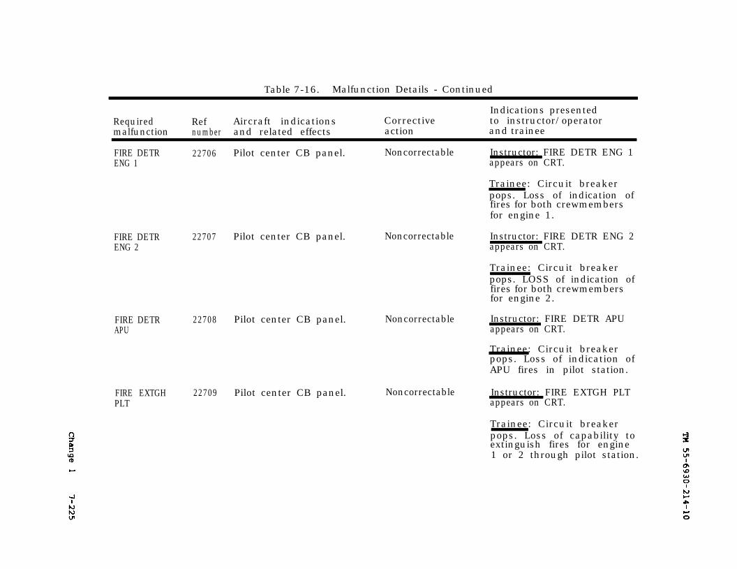
TM 55-6930-214-10
Change 1
7-225
Table 7-16. Malfunction Details - Continued
Indications presentedRequired Ref Aircraft indications Corrective to instructor/operatormalfunction number and related effects action and trainee
FIRE DETR 22706 Pilot center CB panel. Noncorrectable Instructor: FIRE DETR ENG 1ENG 1 appears on CRT.
Trainee: Circuit breakerpops. Loss of indication offires for both crewmembersfor engine 1.
FIRE DETRENG 2
22707 Pilot center CB panel. Noncorrectable
FIRE DETRAPU
22708 Pilot center CB panel. Noncorrectable
Instructor: FIRE DETR ENG 2appears on CRT.
Trainee: Circuit breakerpops. LOSS of indication offires for both crewmembersfor engine 2.
Instructor: FIRE DETR APUappears on CRT.
Trainee: Circuit breakerpops. Loss of indication ofAPU fires in pilot station.
FIRE EXTGHPLT
22709 Pilot center CB panel. Noncorrectable Instructor: FIRE EXTGH PLTappears on CRT.
Trainee: Circuit breakerpops. Loss of capability toextinguish fires for engine1 or 2 through pilot station.
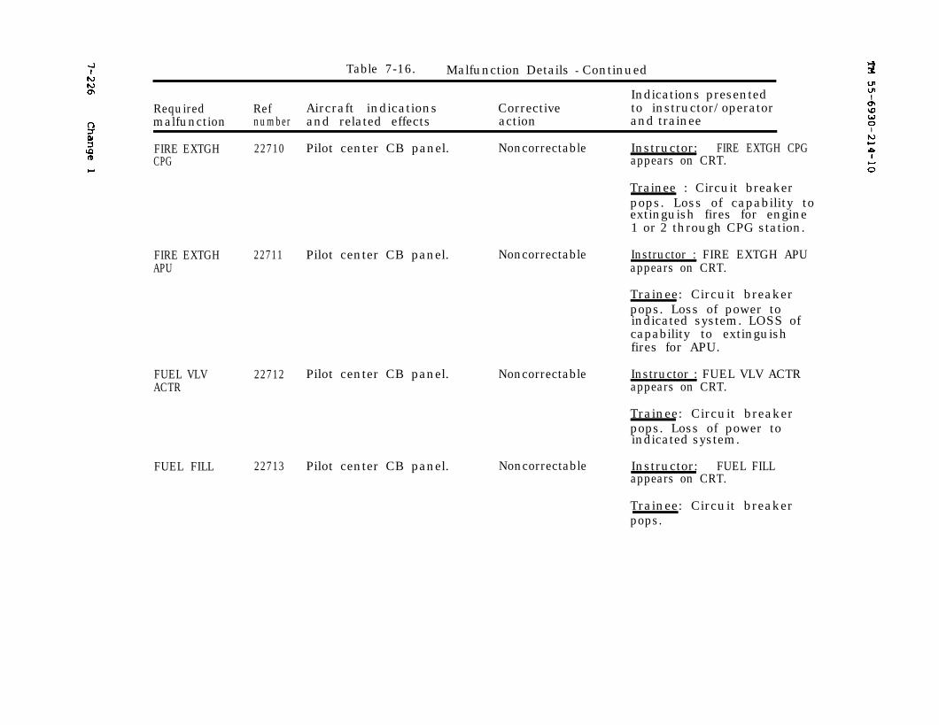
7-226
Change 1
TM 55-6930-214-10
Table 7-16. Malfunction Details - Continued
Indications presentedRequired Ref Aircraft indications Corrective to instructor/operatormalfunction number and related effects action and trainee
FIRE EXTGH 22710CPG
FIRE EXTGHAPU
22711 Pilot center CB panel.
FUEL VLVACTR
FUEL FILL
22712
22713
Pilot center CB panel. Noncorrectable Instructor: FIRE EXTGH CPGappears on CRT.
Trainee : Circuit breakerpops. Loss of capability toextinguish fires for engine1 or 2 through CPG station.
Noncorrectable Instructor : FIRE EXTGH APUappears on CRT.
Trainee: Circuit breakerpops. Loss of power toindicated system. LOSS ofcapability to extinguishfires for APU.
Pilot center CB panel. Noncorrectable Instructor : FUEL VLV ACTRappears on CRT.
Trainee: Circuit breakerpops. Loss of power toindicated system.
Pilot center CB panel. Noncorrectable Instructor: FUEL FILLappears on CRT.
Trainee: Circuit breakerpops.

Change 1
TM 55-6930-214-10
7-227
Table 7-16. Malfunction Details Continued
Indications presentedRequired Ref Aircraft indications Corrective to instructor/operatormalfunction number and related effects action and trainee
FUEL APU 22714 Pilot center CB panel.
ENG WARN 22715
JETT 22716
LT ANTI 22717COL
Noncorrectable Instructor: FUEL APUappears on CRT.
Trainee: Circuit breakerpops. Loss of power to in-dicated system. If running.APU winds down and stops.
Pilot center CB panel. Noncorrectable Instructor: ENG WARN ap-pears on CRT.
Trainee: Loss of power toengine out warning system.
Pilot center CB panel. Noncorrectable Instructor: JETT appears onCRT.
Trainee: If both missionjettison and jettison CB’sare tripped, weapons cannotbe jettisoned.
Pilot center CB panel. Noncorrectable Instructor: LT ANTI COLappears on CRT.
Trainee : Circuit breakerpops.
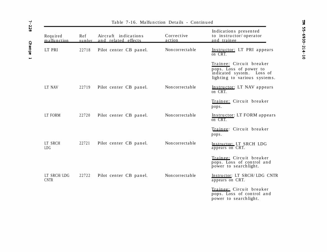
TM 55-6930-214-107-228 Change 1
Table 7-16. Malfunction Details - Continued
Indications presentedRequired Ref Aircraft indications Corrective to instructor/operatormalfunction number and related effects action and trainee
LT PRI 22718 Pilot center CB panel. Noncorrectable
LT NAV
LT FORM
LT SRCHLDG
22719 Pilot center CB panel.
22720 Pilot center CB panel.
22721 Pilot center CB panel.
LT SRCH/LDG 22722 Pilot center CB panel.CNTR
Noncorrectable
Noncorrectable
Noncorrectable
Noncorrectable
Instructor: LT PRI appearson CRT.
Trainee: Circuit breakerpops. Loss of power toindicated system. Loss oflighting to various systems.
Instructor: LT NAV appearson CRT.
Trainee: Circuit breakerpops.
Instructor: LT FORM appearson CRT.
Trainee: Circuit breakerpops.
Instructor: LT SRCH LDGappears on CRT.
Trainee: Circuit breakerpops. Loss of control andpower to searchlight.
Instructor: LT SRCH/LDG CNTRappears on CRT.
Trainee: Circuit breakerpops. Loss of control andpower to searchlight.

Change 2
TM 55-6930-214-10
7-229
Table 7-16. Malfunction Details - Continued
Indications presentedRequired Ref A i r c a f t indications Corrective to instructor/operatormalfunction number and related effects action and trainee
LT CAUT 22723 Pilot center CB panel.
LT UTIL 22724SEC
EMERGHYD
TRIM
22725
22726
Noncorrectable Instructor: LT CAUT appearson CRT.
Trainee: Circuit breakerpops. Loss of power topilot and master caution andwarning panels.
Pilot center CB panel. Noncorrectable Instructor: LT UTIL SECappears on CRT.
Trainee: Circuit breakerpops. Loss of power to PLTUTILITY LT.
Pilot center CB panel. Noncorrectable Instructor: EMERG HYDappears on CRT.
Trainee: Circuit breakerpops. Loss of power toEMERG HYD switch at both sta-tions. Accumulator cannotbe used to control movements.
Pilot center CB panel. Noncorrectable Instructor: TRIM appears onCRT.
Trainee: Circuit breakerpops. Loss of power toindicated system. HSI HDGflag is in view.
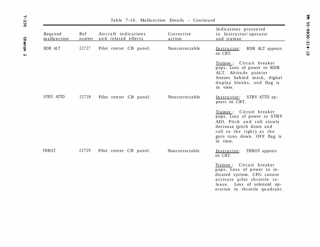
TM 55-6930-214-107-230 Change 2
Table 7-16. Malfunction Details - Continued
Indications presentedRequired Ref Aircraft indications Corrective to Instructor/operatormalfunction number and related effects action and trainee
RDR ALT 22727 Pilot center CB panel. Noncorrectable Instructor: RDR ALT appearson CRT.
Trainee : Circuit breakerpops. Loss of power to RDRALT. Altitude pointerfreezes behind mask, digitaldisplay blanks, and flag isin view.
STBY ATTD 22728 Pilot center CB panel. Noncorrectable Instructor: STBY ATTD ap-pears on CRT.
Trainee : Circuit breakerpops. Loss of power to STBYADI. Pitch and roll slowlydecrease (pitch down androll to the right) as thegyro runs down. OFF flag isin view.
THROT 22729 Pilot center CB panel. Noncorrectable Instructor: THROT appearson CRT.
Trainee : Circuit breakerpops. Loss of power to in-dicated system. CPG cannotactivate pilot throttle re-lease. Loss of solenoid op-eration in throttle quadrant.
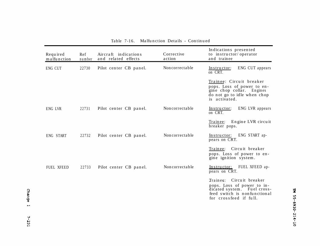
Change 1
TM 55-6930-214-10
7-231
Table 7-16. Malfunction Details - Continued
Indications presentedRequired Ref Aircraft indications Corrective to instructor/operatormalfunction number and related effects action and trainee
ENG CUT 22730 Pilot center CB panel. Noncorrectable
ENG LVR 22731 Pilot center CB panel. Noncorrectable
ENG START 22732 Pilot center CB panel.
FUEL XFEED 22733 Pilot center CB panel.
Noncorrectable
Noncorrectable
Instructor: ENG CUT appearson CRT.
Trainee: Circuit breakerpops. Loss of power to en-gine chop collar. Enginesdo not go to idle when chopis activated.
Instructor: ENG LVR appearson CRT.
Trainee: Engine LVR circuitbreaker pops.
Instructor: ENG START ap-pears on CRT.
Trainee: Circuit breakerpops. Loss of power to en-gine ignition system.
Instructor:pears on CRT.
FUEL XFEED ap-
Trainee: Circuit breaker- -pops. Loss of power to in-dicated system. Fuel cross-feed switch is nonfunctionalfor crossfeed if full.
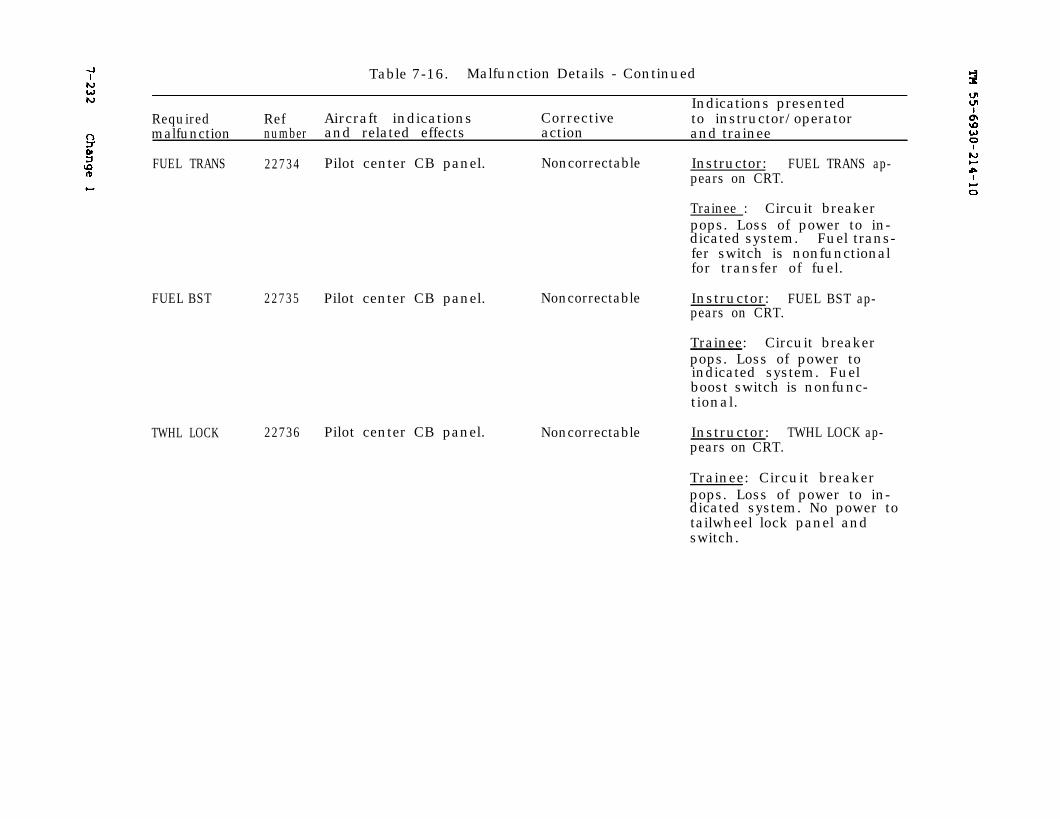
7-232 Change 1 TM 55-6930-214-10
Table 7-16. Malfunction Details - Continued
Indications presentedRequired Ref Aircraft indications Corrective to instructor/operatormalfunction number and related effects action and trainee
FUEL TRANS 22734 Pilot center CB panel. Noncorrectable Instructor: FUEL TRANS ap-pears on CRT.
Trainee : Circuit breakerpops. Loss of power to in-dicated system. Fuel trans-fer switch is nonfunctionalfor transfer of fuel.
FUEL BST 22735 Pilot center CB panel.
TWHL LOCK 22736 Pilot center CB panel.
Noncorrectable Instructor: FUEL BST ap-pears on CRT.
Trainee: Circuit breakerpops. Loss of power toindicated system. Fuelboost switch is nonfunc-tional.
Noncorrectable Instructor: TWHL LOCK ap-pears on CRT.
Trainee: Circuit breakerpops. Loss of power to in-dicated system. No power totailwheel lock panel andswitch.
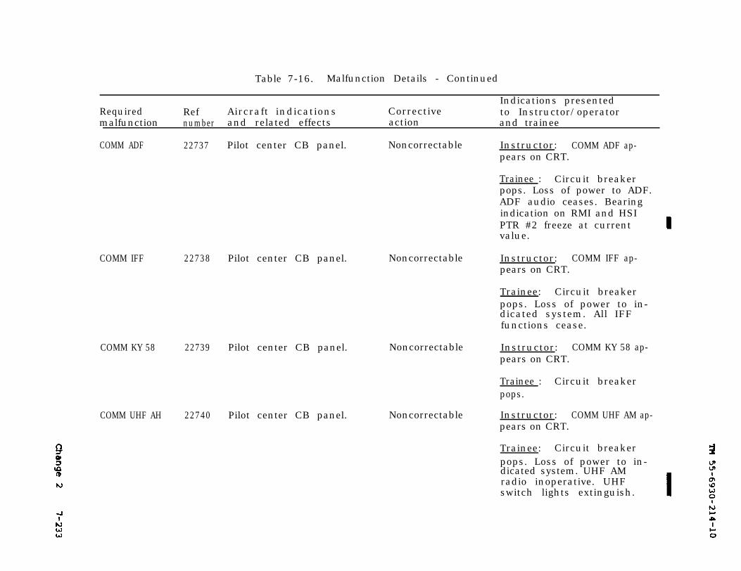
TM 55-6930-214-10
Change 2 7-233
Table 7-16. Malfunction Details - Continued
RequiredIndications presented
Ref Aircraft indications Corrective to Instructor/operatormalfunction number and related effects action and trainee
COMM ADF 22737
COMM IFF 22738 Pilot center CB panel.
COMM KY 58 22739
COMM UHF AH 22740
Pilot center CB panel. Noncorrectable
Noncorrectable
Pilot center CB panel. Noncorrectable
Pilot center CB panel. Noncorrectable
Instructor: COMM ADF ap-pears on CRT.
Trainee : Circuit breakerpops. Loss of power to ADF.ADF audio ceases. Bearingindication on RMI and HSIPTR #2 freeze at currentvalue.
Instructor: COMM IFF ap-pears on CRT.
Trainee: Circuit breakerpops. Loss of power to in-dicated system. All IFFfunctions cease.
Instructor: COMM KY 58 ap-pears on CRT.
Trainee : Circuit breakerpops.
Instructor: COMM UHF AM ap-pears on CRT.
Trainee: Circuit breakerpops. Loss of power to in-dicated system. UHF AMradio inoperative. UHFswitch lights extinguish.
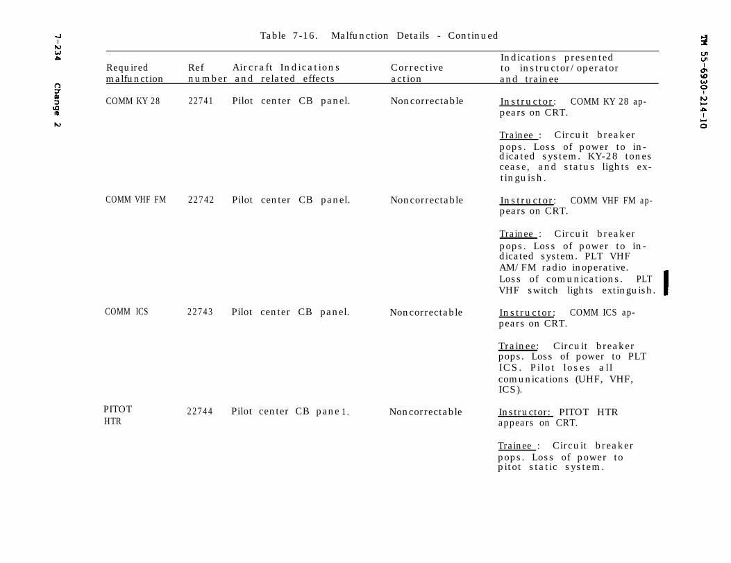
7-234 Change 2
TM 55-6930-214-10
Table 7-16. Malfunction Details - Continued
Indications presentedRequired Ref Aircraft Indications Corrective to instructor/operatormalfunction number and related effects action and trainee
COMM KY 28 22741 Pilot center CB panel. Noncorrectable Instructor: COMM KY 28 ap-pears on CRT.
Trainee : Circuit breakerpops. Loss of power to in-dicated system. KY-28 tonescease, and status lights ex-tinguish.
COMM VHF FM 22742
COMM ICS 22743
PITOTHTR
22744
Pilot center CB panel. Noncorrectable Instructor: COMM VHF FM ap-pears on CRT.
Pilot center CB panel. Noncorrectable
Trainee : Circuit breakerpops. Loss of power to in-dicated system. PLT VHFAM/FM radio inoperative.Loss of comunications. PLTVHF switch lights extinguish.
Instructor: COMM ICS ap-pears on CRT.
Trainee: Circuit breakerpops. Loss of power to PLTICS. Pilot loses allcomunications (UHF, VHF,ICS).
Pilot center CB pane 1. Noncorrectable Instructor: PITOT HTRappears on CRT.
Trainee : Circuit breakerpops. Loss of power topitot static system.
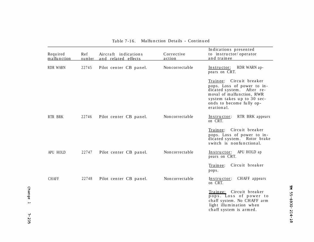
Change 1
TM 55-6930-214-10
7-235
Table 7-16. Malfunction Details - Continued
Indications presentedRequired Ref Aircraft indications Corrective to instructor/operatormalfunction number and related effects action and trainee
RDR WARN 22745 Pilot center CB panel. Noncorrectable Instructor: RDR WARN ap-pears on CRT.
Trainee: Circuit breakerpops. Loss of power to in-dicated system. After re-moval of malfunction, RWRsystem takes up to 30 sec-onds to become fully op-erational.
RTR BRK 22746 Pilot center CB panel. Noncorrectable
APU HOLD 22747 Pilot center CB panel. Noncorrectable
CHAFF 22748 Pilot center CB panel. Noncorrectable
Instructor: RTR BRK appearson CRT.
Trainee: Circuit breakerpops. Loss of power to in-dicated system. Rotor brakeswitch is nonfunctional.
Instructor: APU HOLD appears on CRT.
Trainee: Circuit breakerpops.
Instructor: CHAFF appearson CRT.
Trainee: Circuit breakerpops. Loss of power tochaff system. No CHAFF armlight illumination whenchaff system is armed.
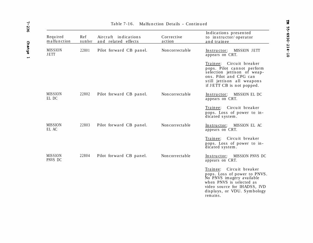
7-236 Change 1 TM 55-6930-214-10
Table 7-16. Malfunction Details - Continued
Indications presentedRequired Ref Aircraft indications Corrective to instructor/operatormalfunction number and related effects action and trainee
MISSION 22801 Pilot forward CB panel. Noncorrectable Instructor: MISSION JETTJETT appears on CRT.
Trainee: Circuit breakerpops. Pilot cannot performselection jettison of weap-ons. Pilot and CPG canstill jettison all weaponsif JETT CB is not popped.
MISSIONEL DC
22802 Pilot forward CB panel. Noncorrectable
MISSIONEL AC
22803 Pilot forward CB panel. Noncorrectable
MISSIONPNVS DC
22804 Pilot forward CB panel. Noncorrectable
Instructor: MISSION EL DCappears on CRT.
Trainee: Circuit breakerpops. Loss of power to in-dicated system.
Instructor: MISSION EL ACappears on CRT.
Trainee: Circuit breakerpops. Loss of power to in-dicated system.
Instructor: MISSION PNVS DCappears on CRT.
Trainee: Circuit breakerpops. Loss of power to PNVS.No PNVS imagery availablewhen PNVS is selected asvideo source for IHADSS, IVDdisplays, or VDU. Symbologyremains.
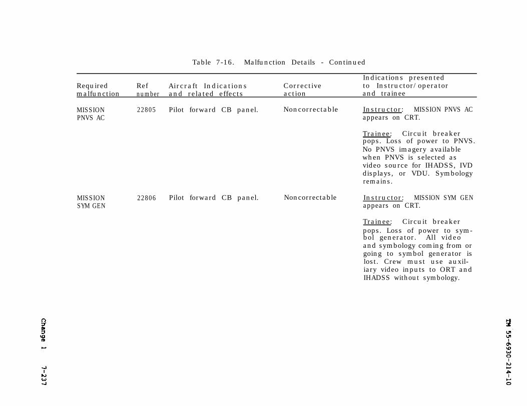
TM 55-6930-214-10
Change 1 7-237
Table 7-16. Malfunction Details - Continued
Indications presentedRequired Ref Aircraft Indications Corrective to Instructor/operatormalfunction number and related effects action and trainee
MISSIONPNVS AC
22805 Pilot forward CB panel.
MISSION 22806SYM GEN
Noncorrectable Instructor: MISSION PNVS ACappears on CRT.
Trainee: Circuit breakerpops. Loss of power to PNVS.No PNVS imagery availablewhen PNVS is selected asvideo source for IHADSS, IVDdisplays, or VDU. Symbologyremains.
Pilot forward CB panel. Noncorrectable Instructor: MISSION SYM GENappears on CRT.
Trainee: Circuit breakerpops. Loss of power to sym-bol generator. All videoand symbology coming from orgoing to symbol generator islost. Crew must use auxil-iary video inputs to ORT andIHADSS without symbology.
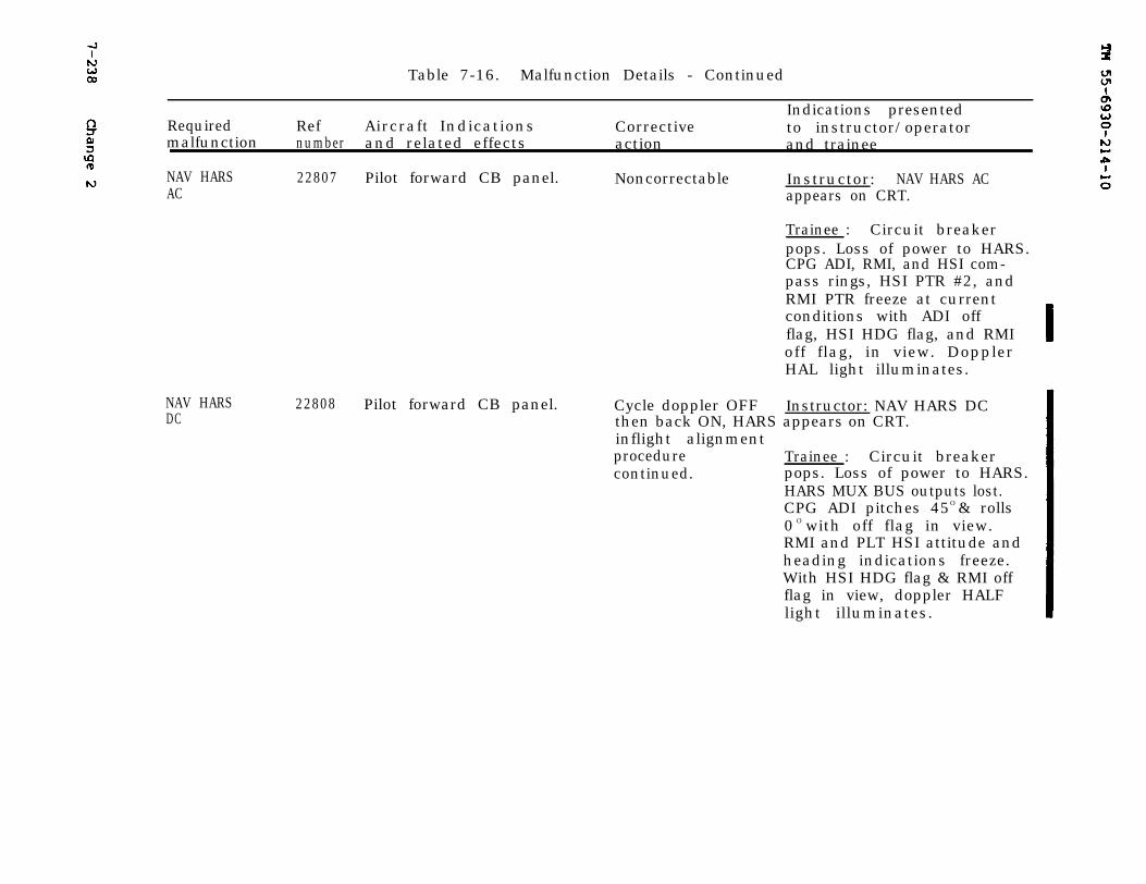
TM 55-6930-214-10
7-238
Change 2
Table 7-16. Malfunction Details - Continued
RequiredIndications presented
Ref Aircraft Indications Corrective to instructor/operatormalfunction number and related effects action and trainee
NAV HARSAC
22807 Pilot forward CB panel. Noncorrectable Instructor: NAV HARS ACappears on CRT.
Trainee : Circuit breakerpops. Loss of power to HARS.CPG ADI, RMI, and HSI com-pass rings, HSI PTR #2, andRMI PTR freeze at currentconditions with ADI offflag, HSI HDG flag, and RMIoff flag, in view. DopplerHAL light illuminates.
NAV HARSDC
22808 Pilot forward CB panel. Cycle doppler OFF Instructor: NAV HARS DCthen back ON, HARS appears on CRT.inflight alignmentprocedure Trainee : Circuit breakercontinued. pops. Loss of power to HARS.
HARS MUX BUS outputs lost.CPG ADI pitches 45O & rolls0 O with off flag in view.RMI and PLT HSI attitude andheading indications freeze.With HSI HDG flag & RMI offflag in view, doppler HALFlight illuminates.
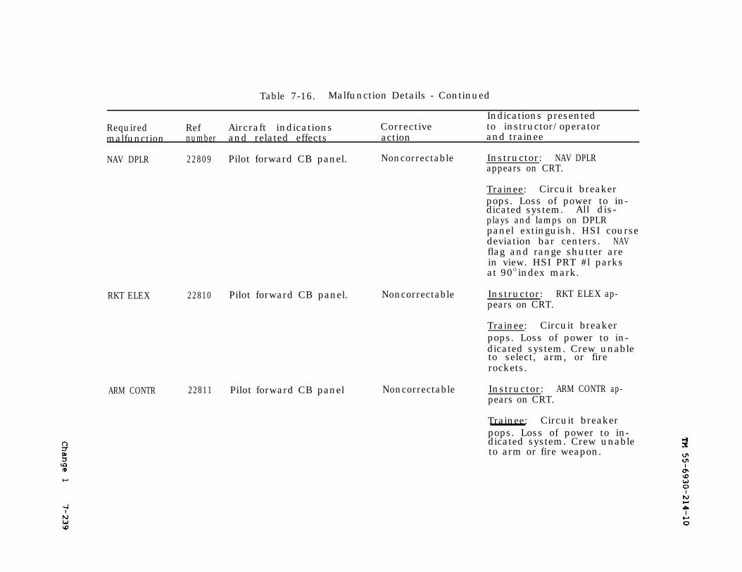
TM 55-6930-214-10
Change 1
7-239
Table 7-16. Malfunction Details - Continued
Indications presentedRequired Ref Aircraft indications Corrective to instructor/operatormalfunction number and related effects action and trainee
NAV DPLR 22809 Pilot forward CB panel. Noncorrectable Instructor: NAV DPLRappears on CRT.
Trainee: Circuit breakerpops. Loss of power to in-dicated system. All dis-plays and lamps on DPLRpanel extinguish. HSI coursedeviation bar centers. NAVflag and range shutter arein view. HSI PRT #l parksat 90O index mark.
RKT ELEX 22810 Pilot forward CB panel. Noncorrectable Instructor: RKT ELEX ap-pears on CRT.
Trainee: Circuit breakerpops. Loss of power to in-dicated system. Crew unableto select, arm, or firerockets.
ARM CONTR 22811 Pilot forward CB panel Noncorrectable Instructor: ARM CONTR ap-pears on CRT.
Trainee: Circuit breakerpops. Loss of power to in-dicated system. Crew unableto arm or fire weapon.
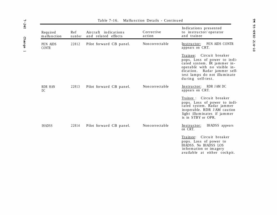
TM 55-6930-214-107-240 Change 1
Table 7-16. Malfunction Details - Continued
Indications presentedRequired Ref Aircraft indications Corrective to instructor/operatormalfunction number and related effects action and trainee
PEN AIDS 22812 Pilot forward CB panel. Noncorrectable Instructor: PEN AIDS CONTRCONTR appears on CRT.
Trainee: Circuit breakerpops. Loss of power to indi-cated system. IR jammer in-operable with no visible in-dication. Radar jammer self-test lamps do not illuminateduring self-test.
RDR HANDC
22813 Pilot forward CB panel. Noncorrectable
IHADSS 22814 Pilot forward CB panel. Noncorrectable
Instructor: RDR JAM DCappears on CRT.
Trainee : Circuit breakerpops. Loss of power to indi-cated system. Radar jammerinoperable. RDR JAM cautionlight illuminates if jammeris in STBY or OPR.
Instructor: IHADSS appearson CRT.
Trainee: Circuit breakerpops. Loss of power toIHADSS. No IHADSS LOSinformation or imageryavailable at either cockpit.
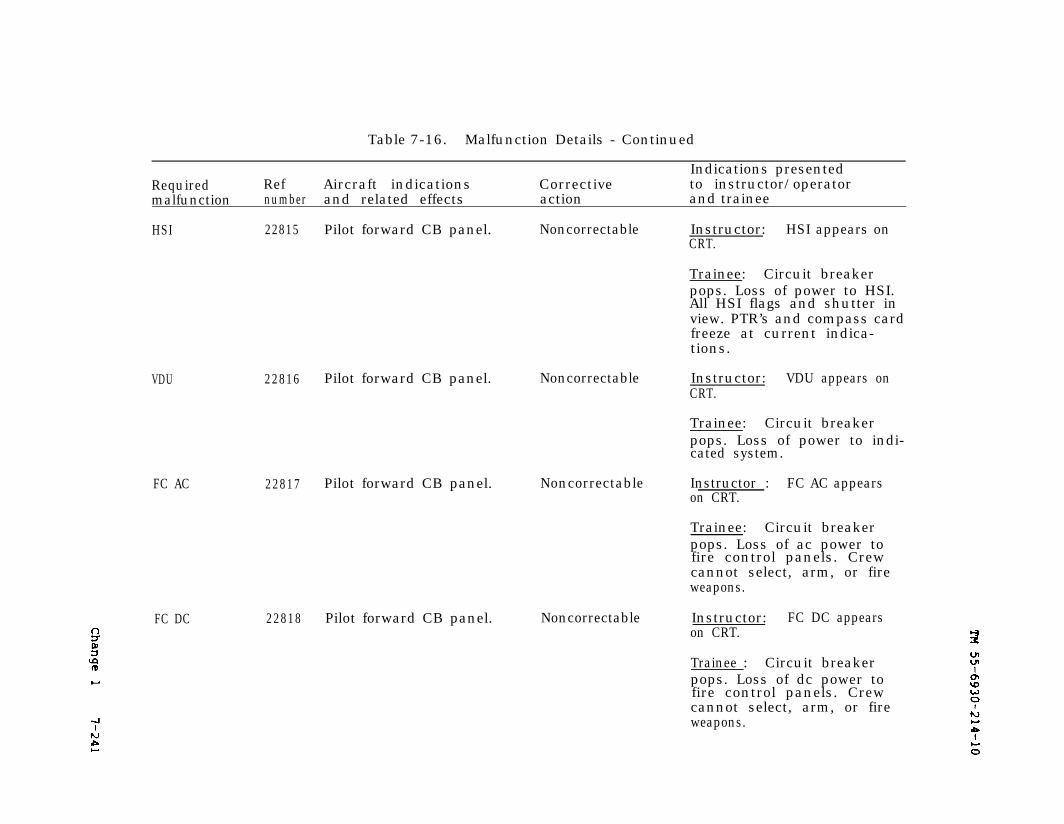
Change 1
TM 55-6930-214-10
7-241
Table 7-16. Malfunction Details - Continued
Indications presentedRequired Ref Aircraft indications Corrective to instructor/operatormalfunction number and related effects action and trainee
HSI 22815
VDU
FC AC 22817
FC DC
22816
22818
Pilot forward CB panel. Noncorrectable Instructor: HSI appears onCRT.
Trainee: Circuit breakerpops. Loss of power to HSI.All HSI flags and shutter inview. PTR’s and compass cardfreeze at current indica-tions.
Pilot forward CB panel. Noncorrectable Instructor: VDU appears onCRT.
Trainee: Circuit breakerpops. Loss of power to indi-cated system.
Pilot forward CB panel. Noncorrectable Instructor : FC AC appearson CRT.
Trainee: Circuit breakerpops. Loss of ac power tofire control panels. Crewcannot select, arm, or fireweapons.
Pilot forward CB panel. Noncorrectable Instructor: FC DC appearson CRT.
Trainee : Circuit breakerpops. Loss of dc power tofire control panels. Crewcannot select, arm, or fireweapons.
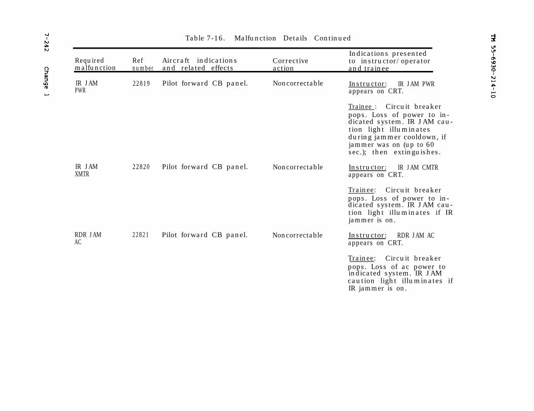
7-242 Change 1TM 55-6930-214-10
Table 7-16. Malfunction Details Continued
Indications presentedRequired Ref Aircraft indications Corrective to instructor/operatormalfunction number and related effects action and trainee
IR JAM 22819 NoncorrectablePilot forward CB panel. Instructor: IR JAM PWRPWR appears on CRT.
Trainee : Circuit breakerpops. Loss of power to in-dicated system. IR JAM cau-tion light illuminatesduring jammer cooldown, ifjammer was on (up to 60sec.); then extinguishes.
IR JAMXMTR
RDR JAMAC
22820 Pilot forward CB panel.
22821 Pilot forward CB panel.
Noncorrectable Instructor: IR JAM CMTRappears on CRT.
Trainee: Circuit breakerpops. Loss of power to in-dicated system. IR JAM cau-tion light illuminates if IRjammer is on.
Noncorrectable Instructor: RDR JAM ACappears on CRT.
Trainee: Circuit breakerpops. Loss of ac power toindicated system. IR JAMcaution light illuminates ifIR jammer is on.
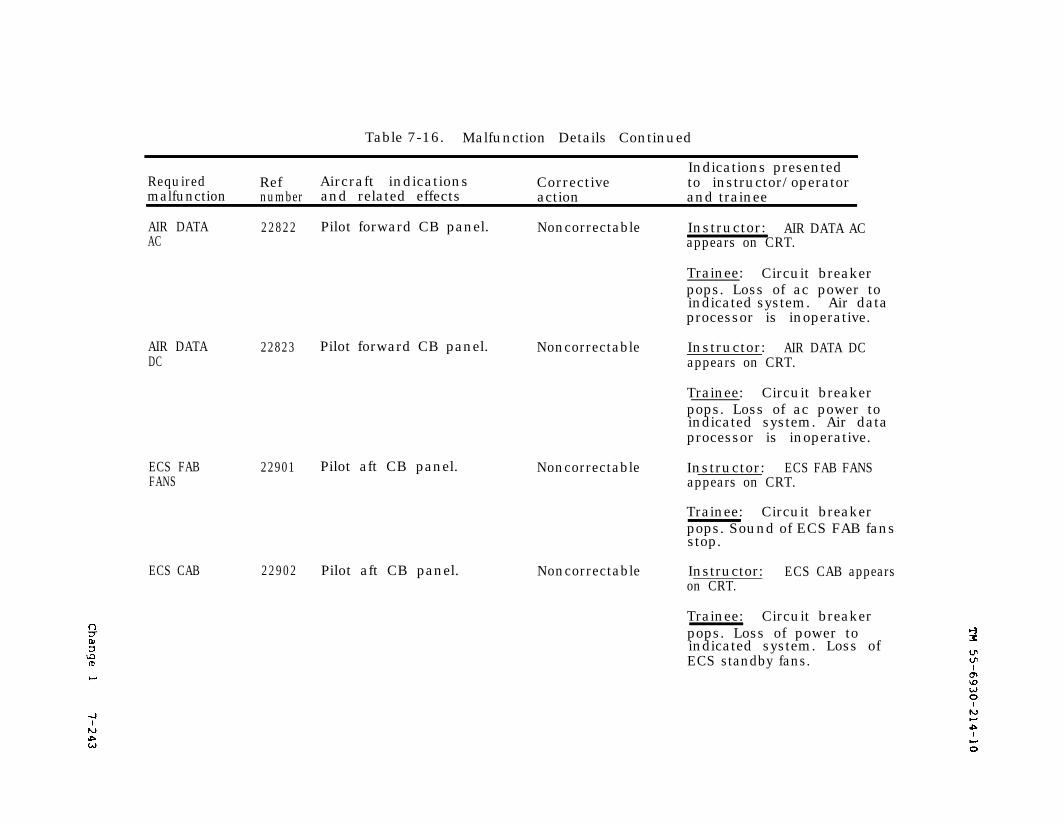
Change 1
TM 55-6930-214-10
7-243
Table 7-16. Malfunction Details Continued
Indications presentedRequired Ref Aircraft indications Corrective to instructor/operatormalfunction number and related effects action and trainee
AIR DATAAC
22822 Pilot forward CB panel. Noncorrectable
AIR DATADC
22823 Pilot forward CB panel. Noncorrectable
ECS FABFANS
ECS CAB
22901 Pilot aft CB panel.
22902 Pilot aft CB panel.
Noncorrectable
Noncorrectable
Instructor: AIR DATA ACappears on CRT.
Trainee: Circuit breakerpops. Loss of ac power toindicated system. Air dataprocessor is inoperative.
Instructor: AIR DATA DCappears on CRT.
Trainee: Circuit breakerpops. Loss of ac power toindicated system. Air dataprocessor is inoperative.
Instructor: ECS FAB FANSappears on CRT.
Trainee: Circuit breakerpops. Sound of ECS FAB fansstop.
Instructor: ECS CAB appearson CRT.
Trainee: Circuit breakerpops. Loss of power toindicated system. Loss ofECS standby fans.
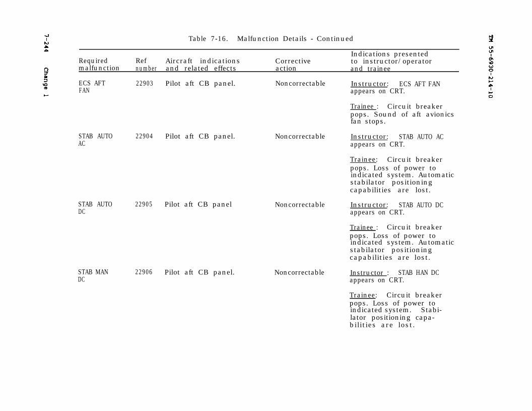
7-244
TM 55-6930-214-10
Change 1
Table 7-16. Malfunction Details - Continued
RequiredIndications presented
Ref Aircraft indications Correctivemalfunction
to instructor/operatornumber and related effects action and trainee
ECS AFT 22903 Pilot aft CB panel. Noncorrectable Instructor: ECS AFT FANFAN appears on CRT.
STAB AUTOAC
22904 Pilot aft CB panel.
STAB AUTODC
22905 Pilot aft CB panel
STAB MANDC
22906 Pilot aft CB panel.
Trainee : Circuit breakerpops. Sound of aft avionicsfan stops.
Noncorrectable Instructor: STAB AUTO ACappears on CRT.
Trainee: Circuit breakerpops. Loss of power toindicated system. Automaticstabilator positioningcapabilities are lost.
Noncorrectable Instructor: STAB AUTO DCappears on CRT.
Trainee : Circuit breakerpops. Loss of power toindicated system. Automaticstabilator positioningcapabilities are lost.
Noncorrectable Instructor : STAB HAN DCappears on CRT.
Trainee: Circuit breakerpops. Loss of power toindicated system. Stabi-lator positioning capa-bilities are lost.

Change 1
TM 55-6930-214-10
7-245
Table 7-16. Malfunction Details - Continued
Indications presentedRequired Ref Aircraft indications Corrective to instructor/operatormalfunction number and related effects action and trainee
STAB MAN 22907 Pilot aft CB panel. Noncorrectable Instructor: STAB MAN ACAC appears on CRT.
Trainee : Circuit breakerpops. Loss of power toindicated system. Stabi-lator positioning capa-bilities are lost.
WSHLDWPR
22908 Pilot aft CB panel.
ICE DET 22909 Pilot aft CB panel.
BLADE DEICE 22910 Pilot aft CB panel.CONT
Noncorrectable
Noncorrectable
Noncorrectable
Instructor: WSHLD WPRappears on CRT.
Trainee: Circuit breakerpops.
Instructor: ICE DET appearson CRT.
Trainee: Circuit breakerpops. Loss of power to in-dicated system. Automaticrotor blade deice functioninoperable.
Instructor: BLADE DEICECONT appears on CRT.
Trainee: Circuit breakerpops. Loss of power toindicated system. Bladedeicing capability is lost.
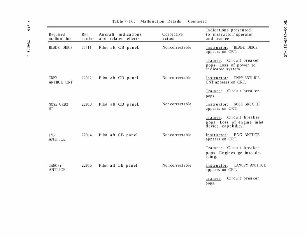
7-246
TM 55-6930-214-10
Change 1
Table 7-16. Malfunction Details Continued
Required Ref Aircraft indications Correctivemalfunction number and related effects action
BLADE DEICE 22911 Pilot aft CB panel. Noncorrectable
CNPY 22912 Pilot aft CB panel.ANTIICE CNT
NOSE GRBXHT
22913 Pilot aft CB panel. Noncorrectable
ENGANTI ICE
22914 Pilot aft CB panel
CANOPYANTI ICE
22915 Pilot aft CB panel
Noncorrectable
Noncorrectable
Noncorrectable
Indications presentedto instructor/operatorand trainee
Instructor: BLADE DEICEappears on CRT.
Trainee: Circuit breakerpops. Loss of power toindicated system.
Instructor: CNPY ANTI ICECNT appears on CRT.
Trainee: Circuit breakerpops.
Instructor: NOSE GRBX HTappears on CRT.
Trainee: Circuit breakerpops. Loss of engine inletdevice capability.
Instructor: ENG ANTIICEappears on CRT.
Trainee: Circuit breakerpops. Engines go into de-icing.
Instructor: CANOPY ANTI ICEappears on CRT.
Trainee: Circuit breakerpops.
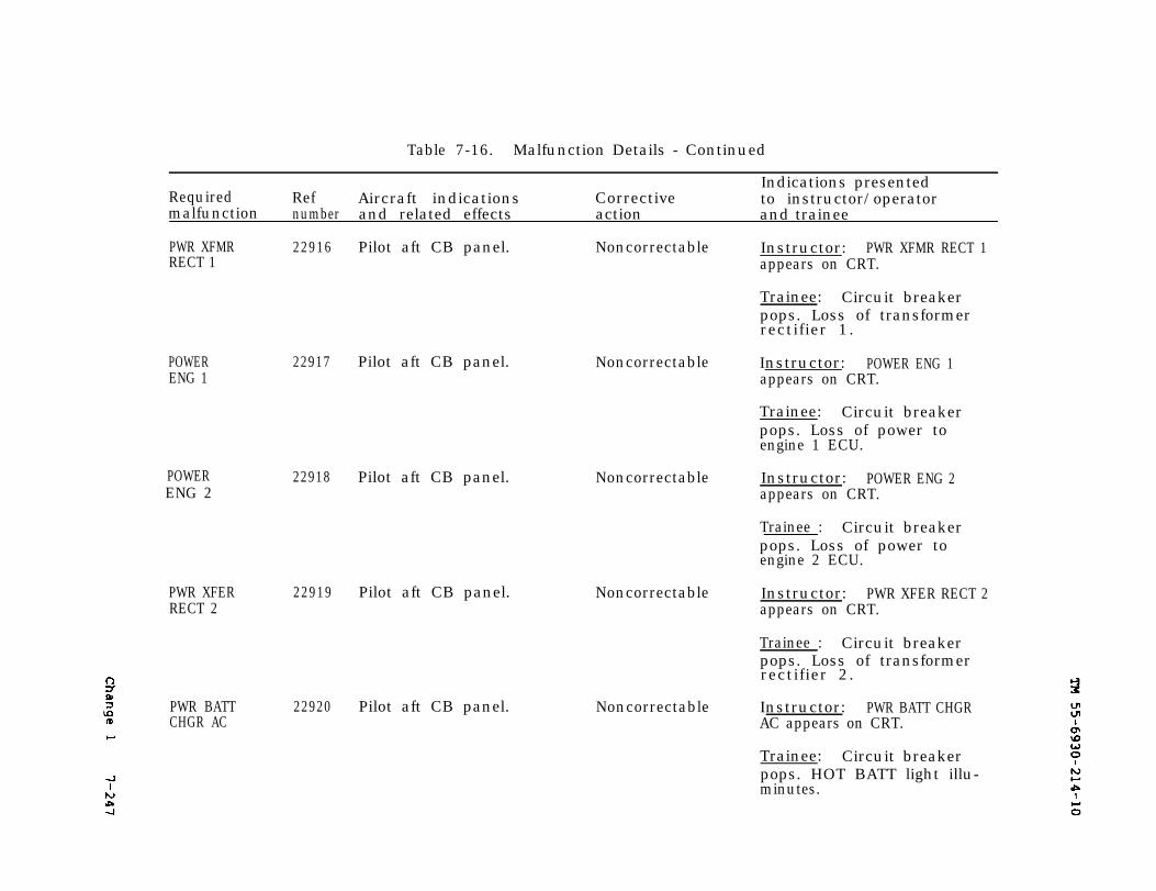
TM 55-6930-214-10
7-247
Change 1
Table 7-16. Malfunction Details - Continued
Indications presentedRequired Ref Aircraft indications Corrective to instructor/operatormalfunction number and related effects action and trainee
PWR XFMRRECT 1
22916 Pilot aft CB panel. Noncorrectable
POWERENG 1
22917 Pilot aft CB panel.
POWERENG 2
22918 Pilot aft CB panel.
PWR XFERRECT 2
22919 Pilot aft CB panel. Noncorrectable
PWR BATT 22920 Pilot aft CB panel.CHGR AC
Noncorrectable
Noncorrectable
Noncorrectable
Instructor: PWR XFMR RECT 1appears on CRT.
Trainee: Circuit breakerpops. Loss of transformerrectifier 1.
Instructor: POWER ENG 1appears on CRT.
Trainee: Circuit breakerpops. Loss of power toengine 1 ECU.
Instructor: POWER ENG 2appears on CRT.
Trainee : Circuit breakerpops. Loss of power toengine 2 ECU.
Instructor: PWR XFER RECT 2appears on CRT.
Trainee : Circuit breakerpops. Loss of transformerrectifier 2.
Instructor: PWR BATT CHGRAC appears on CRT.
Trainee: Circuit breakerpops. HOT BATT light illu-minutes.
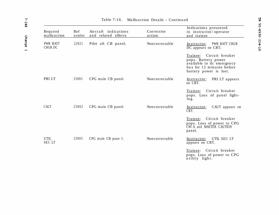
7-248
Change 1
TM 55-6930-214-10
Table 7-16. Malfunction Details - Continued
Indications presentedRequired Ref Aircraft indications Corrective to instructor/operatormalfunction number and related effects action and trainee
PWR BATT 22921 Pilot aft CB panel. Noncorrectable Instructor: PWR BATT CHGRCHGR DC DC appears on CRT.
Trainee: Circuit breakerpops. Battery poweravailable to dc emergencybus for 12 minutes beforebattery power is lost.
PRI LT 23001 CPG main CB panel.
CAUT
UTILSEC LT
23002 CPG main CB panel.
23003 CPG main CB pane 1.
Noncorrectable Instructor: PRI LT appearson CRT.
Trainee: Circuit breakerpops. Loss of panel light-ing.
Noncorrectable Instructor: CAUT appears onCRT.
Trainee: Circuit breakerpops. Loss of power to CPGCW/A and MASTER CAUTIONpanel.
Noncorrectable Instructor: UTIL SEC LTappears on CRT.
Trainee: Circuit breakerpops. Loss of power to CPGutility light.
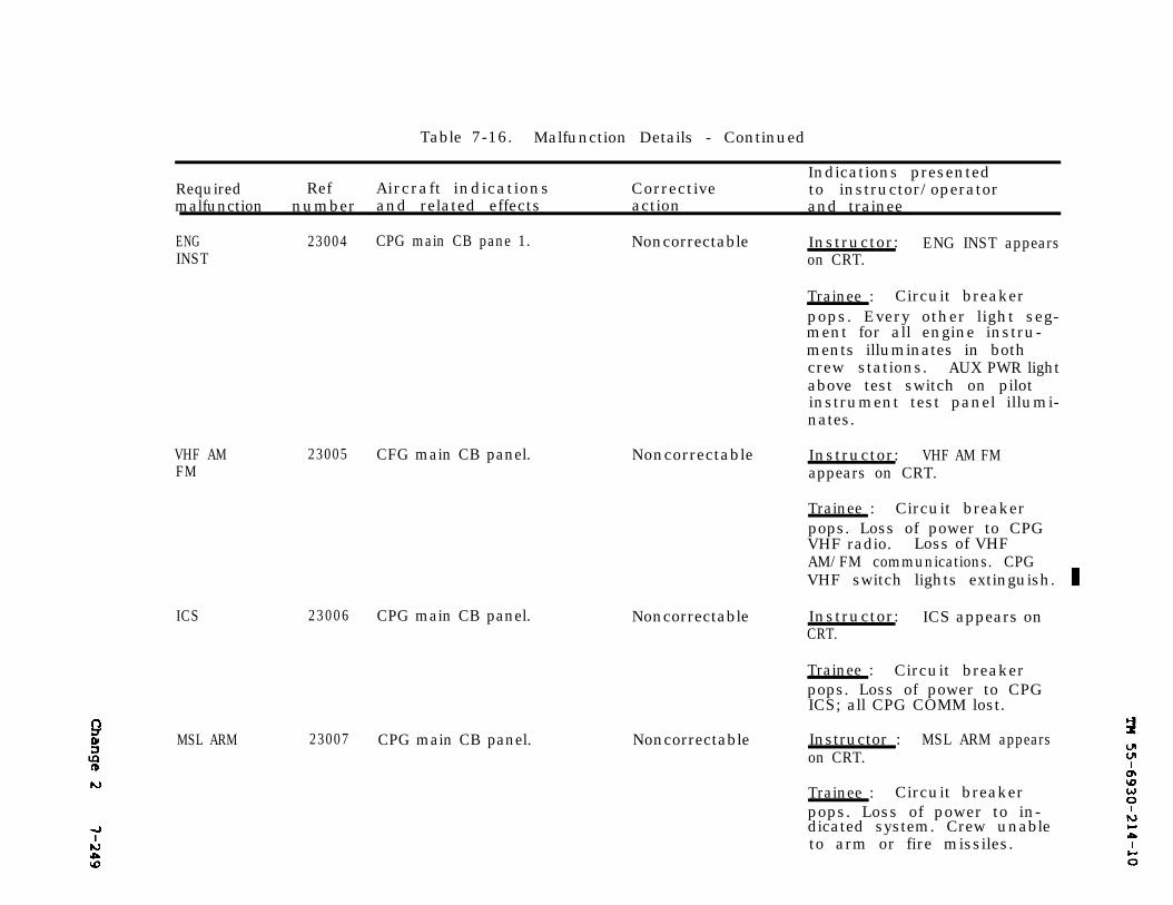
TM 55-6930-214-10Change 2 7-249
Table 7-16. Malfunction Details - Continued
Indications presentedRequired Ref Aircraft indications Corrective to instructor/operatormalfunction number and related effects action and trainee
ENGINST
23004 CPG main CB pane 1. Noncorrectable
VHF AMFM
ICS
23005 CFG main CB panel.
23006 CPG main CB panel.
MSL ARM 23007 CPG main CB panel.
Instructor: ENG INST appearson CRT.
Trainee : Circuit breakerpops. Every other light seg-ment for all engine instru-ments illuminates in bothcrew stations. AUX PWR lightabove test switch on pilotinstrument test panel illumi-nates.
Noncorrectable Instructor: VHF AM FMappears on CRT.
Trainee : Circuit breakerpops. Loss of power to CPGVHF radio. Loss of VHFAM/FM communications. CPGVHF switch lights extinguish.
Noncorrectable Instructor: ICS appears onCRT.
Trainee : Circuit breakerpops. Loss of power to CPGICS; all CPG COMM lost.
Noncorrectable Instructor : MSL ARM appearson CRT.
Trainee : Circuit breakerpops. Loss of power to in-dicated system. Crew unableto arm or fire missiles.
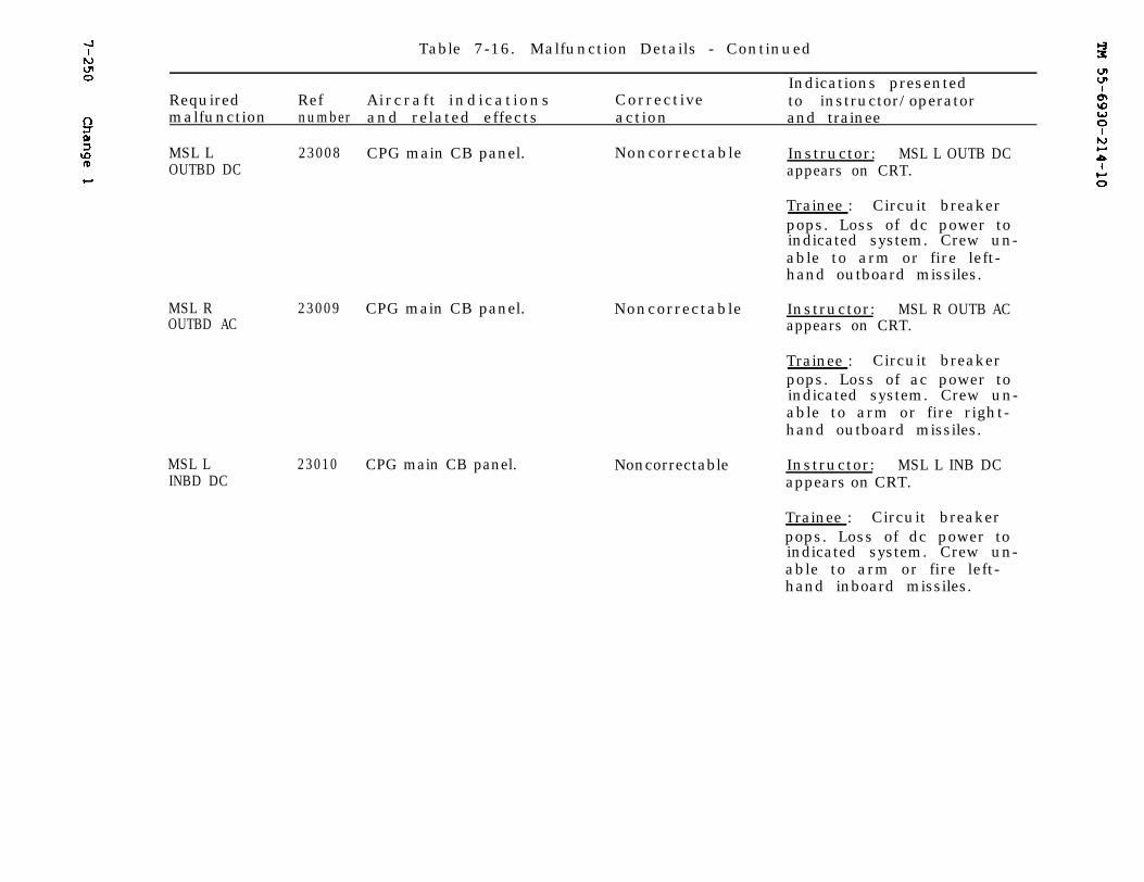
TM 55-6930-214-107-250 Change 1
Table 7-16. Malfunction Details - Continued
Indications presentedRef Aircraft indications Corrective to instructor/operatorRequired
malfunction number and related effects action and trainee
MSL L 23008 CPG main CB panel. Noncorrectable Instructor: MSL L OUTB DCOUTBD DC appears on CRT.
MSL ROUTBD AC
23009 CPG main CB panel.
MSL LINBD DC
23010 CPG main CB panel.
Trainee : Circuit breakerpops. Loss of dc power toindicated system. Crew un-able to arm or fire left-hand outboard missiles.
Noncorrectable Instructor: MSL R OUTB ACappears on CRT.
Trainee : Circuit breakerpops. Loss of ac power toindicated system. Crew un-able to arm or fire right-hand outboard missiles.
Noncorrectable Instructor: MSL L INB DCappears on CRT.
Trainee : Circuit breakerpops. Loss of dc power toindicated system. Crew un-able to arm or fire left-hand inboard missiles.
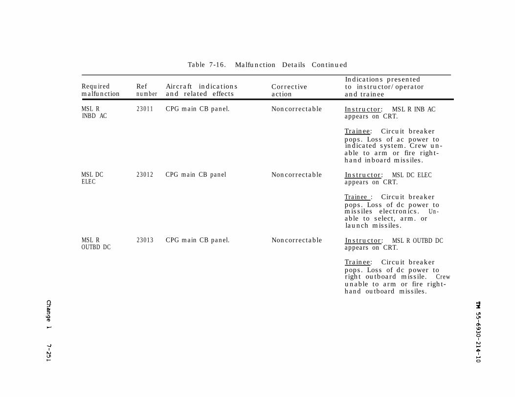
Change 1
TM 55-6930-214-10
7-251
Table 7-16. Malfunction Details Continued
Indications presentedRequired Ref Aircraft indications Corrective to instructor/operatormalfunction number and related effects action and trainee
MSL R 23011 CPG main CB panel. Noncorrectable Instructor: MSL R INB ACINBD AC appears on CRT.
Trainee: Circuit breakerpops. Loss of ac power toindicated system. Crew un-able to arm or fire right-hand inboard missiles.
MSL DCELEC
23012 CPG main CB panel
MSL ROUTBD DC
23013 CPG main CB panel.
Noncorrectable Instructor: MSL DC ELECappears on CRT.
Trainee : Circuit breakerpops. Loss of dc power tomissiles electronics. Un-able to select, arm. orlaunch missiles.
Noncorrectable Instructor: MSL R OUTBD DCappears on CRT.
Trainee: Circuit breakerpops. Loss of dc power toright outboard missile. Crewunable to arm or fire right-hand outboard missiles.
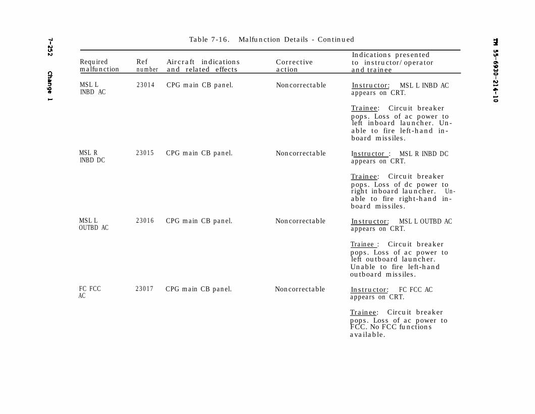
7-252 Change 1TM 55-6930-214-10
Table 7-16. Malfunction Details - Continued
Indications presentedRequired Ref Aircraft indications Corrective to instructor/operatormalfunction number and related effects action and trainee
MSL L 23014 CPG main CB panel. Noncorrectable Instructor: MSL L INBD ACINBD AC appears on CRT.
Trainee: Circuit breakerpops. Loss of ac power toleft inboard launcher. Un-able to fire left-hand in-board missiles.
MSL RINBD DC
23015 CPG main CB panel. Noncorrectable
MSL LOUTBD AC
23016 CPG main CB panel.
FC FCCAC
23017 CPG main CB panel.
Noncorrectable
Instructor : MSL R INBD DCappears on CRT.
Trainee: Circuit breakerpops. Loss of dc power toright inboard launcher. Un-able to fire right-hand in-board missiles.
Instructor: MSL L OUTBD ACappears on CRT.
Trainee : Circuit breakerpops. Loss of ac power toleft outboard launcher.Unable to fire left-handoutboard missiles.
Noncorrectable Instructor: FC FCC ACappears on CRT.
Trainee: Circuit breakerpops. Loss of ac power toFCC. No FCC functionsavailable.
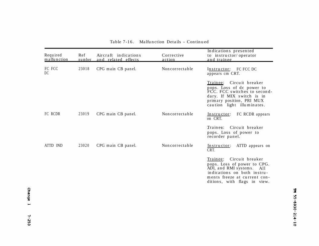
Change 1
TM 55-6930-214-10
7-253
Table 7-16. Malfunction Details - Continued
RequiredIndications presented
Ref Aircraft indications Correctivemalfunction
to instructor/operatornumber and related effects action and trainee
FC FCC 23018 CPG main CB panel. Noncorrectable Instructor: FC FCC DCDC appears cm CRT.
Trainee: Circuit breakerpops. Loss of dc power toFCC. FCC switches to second-dary. If MIX switch is inprimary position, PRI MUXcaution light illuminates.
ATTD IND 23020 CPG main CB panel.
Noncorrectable Instructor: FC RCDR appearson CRT.
Trainee: Circuit breaker- -pops. Loss of power torecorder panel.
Noncorrectable Instructor: ATTD appears onCRT.
Trainee: Circuit breakerpops. Loss of power to CPG.ADI, and RMI systems. Allindications on both instru-ments freeze at current con-ditions, with flags in view.
FC RCDR 23019 CPG main CB panel.
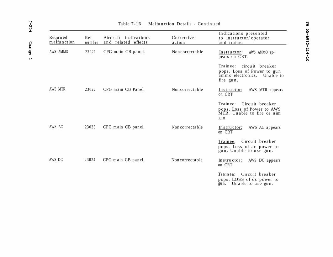
TM 55-6930-214-107-254 Change 1
Table 7-16. Malfunction Details - Continued
Indications presentedRequired Ref Aircraft indications Corrective to instructor/operatormalfunction number and related effects action and trainee
AWS AMMO 23021 CPG main CB panel. Noncorrectable Instructor: AWS AMMO ap-pears on CRT.
Trainee: circuit breakerpops. Loss of Power to gunammo electronics. Unable tofire gun.
AWS MTR 23022 CPG main CB Panel.
AWS AC
AWS DC
23023 CPG main CB panel.
23024 CPG main CB panel.
Noncorrectable
Noncorrectable
Noncorrectable
Instructor: AWS MTR appearson CRT.
Trainee: Circuit breakerpops. Loss of Power to AWSMTR. Unable to fire or aimgun.
Instructor: AWS AC appearson CRT.
Trainee: Circuit breakerpops. Loss of ac power togun. Unable to use gun.
Instructor: AWS DC appearson CRT.
Trainee: Circuit breaker- -pops. LOSS of dc power togun. Unable to use gun.
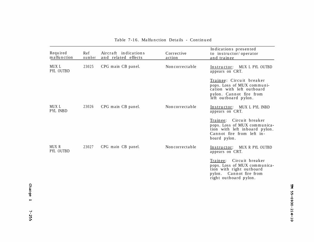
Change 1
TM 55-6930-214-10
7-255
Table 7-16. Malfunction Details - Continued
Indications presentedRequired Ref Aircraft indications Correctivemalfunction
to instructor/operatornumber and related effects action and trainee
MUX L 23025 CPG main CB panel. Noncorrectable Instructor: MUX L PYL OUTBDPYL OUTBD appears on CRT.
Trainee: Circuit breakerpops. Loss of MUX communi-cation with left outboardpylon. Cannot fire fromleft outboard pylon.
MUX LPYL INBD
23026 CPG main CB panel.
MUX RPYL OUTBD
23027 CPG main CB panel.
Noncorrectable Instructor: MUX L PYL INBDappears on CRT.
Trainee: Circuit breakerpops. Loss of MUX communica-tion with left inboard pylon.Cannot fire from left in-board pylon.
Noncorrectable Instructor: MUX R PYL OUTBDappears on CRT.
Trainee: Circuit breakerpops. Loss of MUX communica-tion with right outboardpylon. Cannot fire fromright outboard pylon.
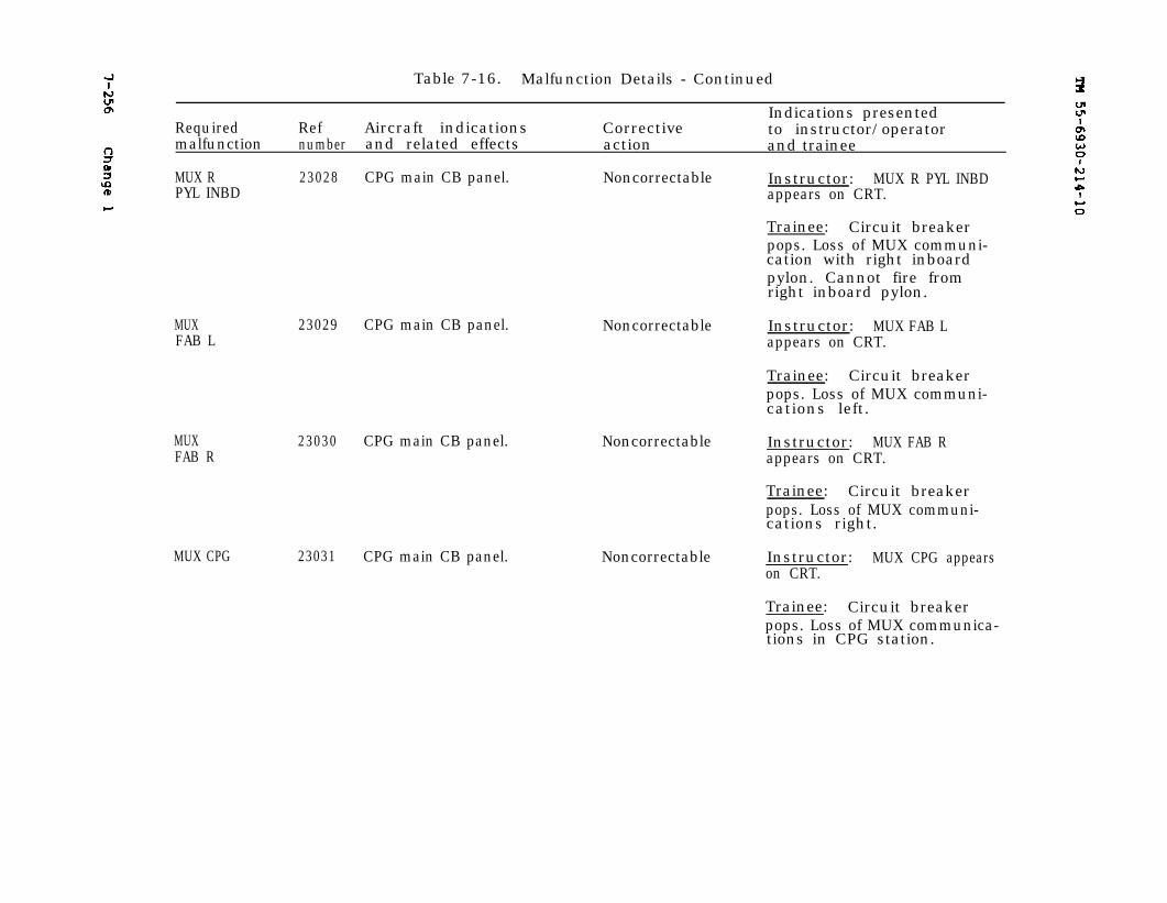
7-256 Change 1
TM 55-6930-214-10
Table 7-16. Malfunction Details - Continued
Indications presentedRequired Ref Aircraft indications Corrective to instructor/operatormalfunction number and related effects action and trainee
MUX R 23028 CPG main CB panel. Noncorrectable Instructor: MUX R PYL INBDPYL INBD appears on CRT.
Trainee: Circuit breakerpops. Loss of MUX communi-cation with right inboardpylon. Cannot fire fromright inboard pylon.
MUXFAB L
MUXFAB R
23029 CPG main CB panel.
23030 CPG main CB panel.
MUX CPG 23031 CPG main CB panel.
Noncorrectable
Noncorrectable
Noncorrectable
Instructor: MUX FAB Lappears on CRT.
Trainee: Circuit breakerpops. Loss of MUX communi-cations left.
Instructor: MUX FAB Rappears on CRT.
Trainee: Circuit breakerpops. Loss of MUX communi-cations right.
Instructor: MUX CPG appearson CRT.
Trainee: Circuit breakerpops. Loss of MUX communica-tions in CPG station.
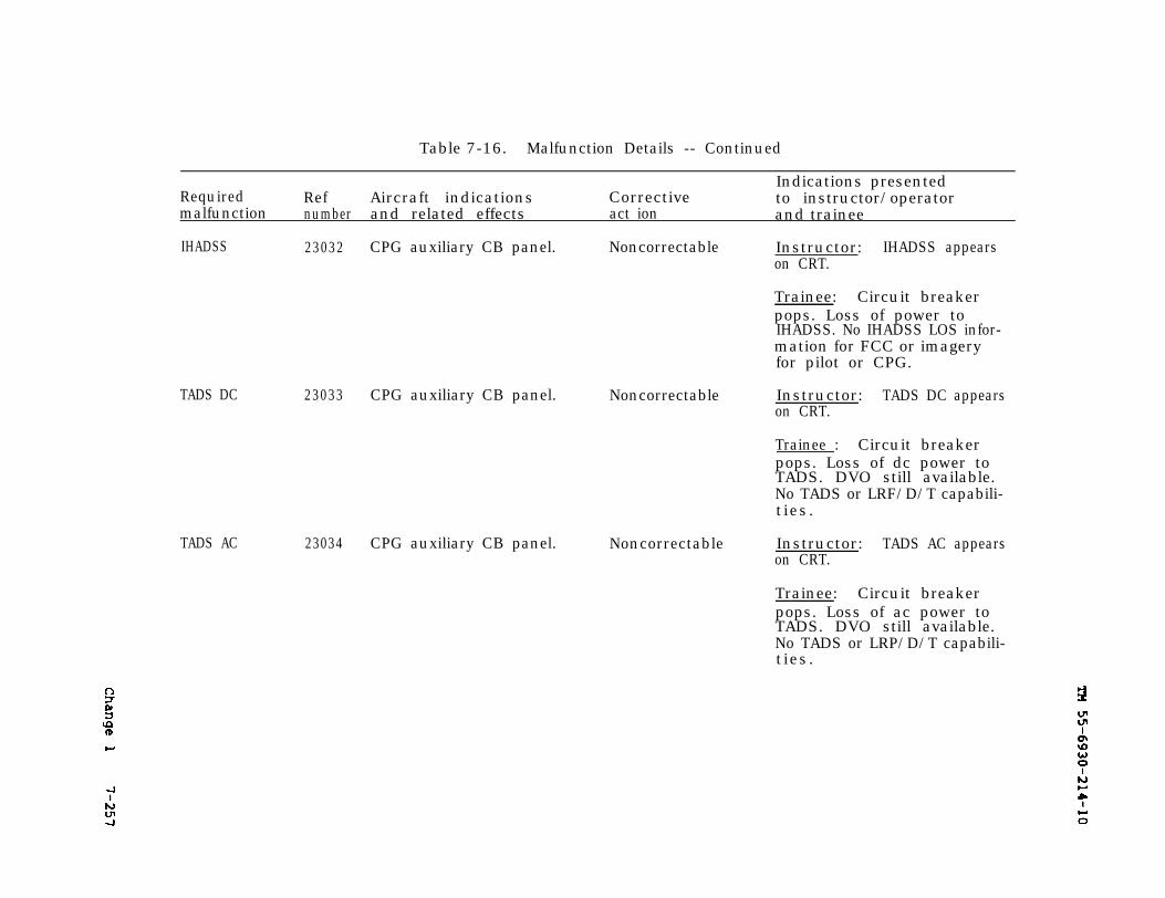
TM 55-6930-214-10
7-257
TM 55-6930-214-10 7-2577-257
Table 7-16. Malfunction Details -- Continued
Indications presentedRequired Ref Aircraft indications Corrective to instructor/operatormalfunction number and related effects act ion and trainee
IHADSS 23032 CPG auxiliary CB panel. Noncorrectable Instructor: IHADSS appearson CRT.
Trainee: Circuit breakerpops. Loss of power toIHADSS. No IHADSS LOS infor-mation for FCC or imageryfor pilot or CPG.
TADS DC 23033 CPG auxiliary CB panel. Noncorrectable Instructor: TADS DC appearson CRT.
Trainee : Circuit breakerpops. Loss of dc power toTADS. DVO still available.No TADS or LRF/D/T capabili-ties.
TADS AC 23034 CPG auxiliary CB panel. Noncorrectable Instructor: TADS AC appearson CRT.
Trainee: Circuit breakerpops. Loss of ac power toTADS. DVO still available.No TADS or LRP/D/T capabili-ties.
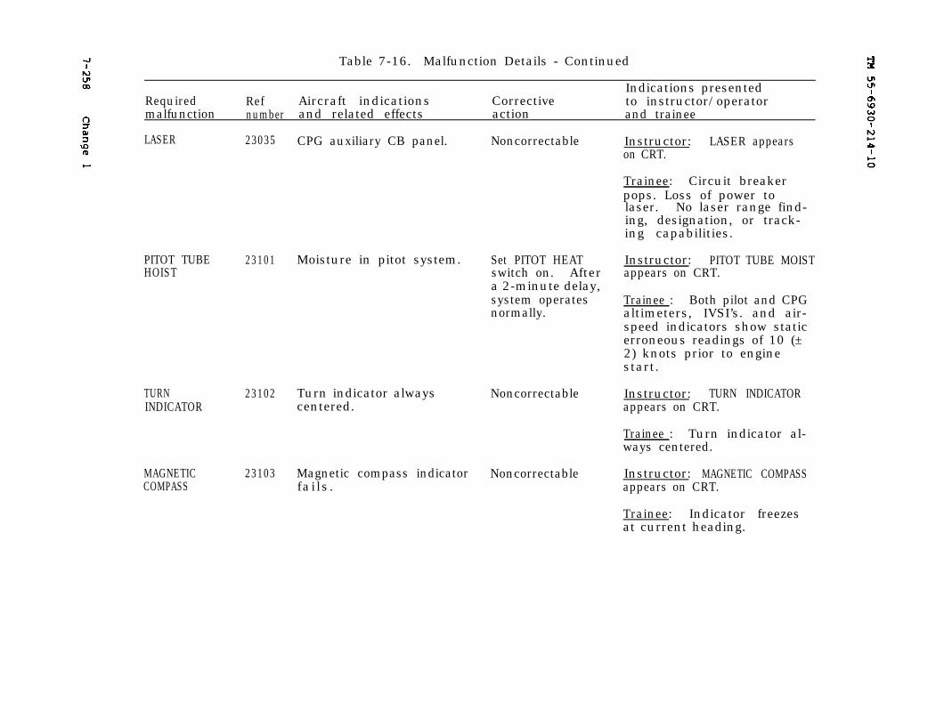
7-258 TM 55-6930-214-10
Table 7-16. Malfunction Details - Continued
Indications presentedRequired Ref Aircraft indications Corrective to instructor/operatormalfunction number and related effects action and trainee
LASER 23035
PITOT TUBEHOIST
23101
CPG auxiliary CB panel. Noncorrectable
Moisture in pitot system. Set PITOT HEATswitch on. Aftera 2-minute delay,system operatesnormally.
TURNINDICATOR
23102 Turn indicator alwayscentered.
Noncorrectable
MAGNETICCOMPASS
23103 Magnetic compass indicator Noncorrectablefails.
Instructor: LASER appearson CRT.
Trainee: Circuit breakerpops. Loss of power tolaser. No laser range find-ing, designation, or track-ing capabilities.
Instructor: PITOT TUBE MOISTappears on CRT.
Trainee : Both pilot and CPGaltimeters, IVSI’s. and air-speed indicators show staticerroneous readings of 10 (±2) knots prior to enginestart.
Instructor: TURN INDICATORappears on CRT.
Trainee : Turn indicator al-ways centered.
Instructor: MAGNETIC COMPASSappears on CRT.
Trainee: Indicator freezesat current heading.

7-259
TM 55-6930-214-10TM 55-6930-214-10
7-259
Table 7-16. Malfunction Details - continued
Indications presentedRequired Ref Aircraft Indications Corrective to instructor/operatormalfunction number and related effects action and trainee
RADAR 23104 Radar altimeter cannot lock NoncorrectableALTIMETER onto a valid signal.
PILOT ATTIND
23105
Instructor: RADAR ALTIMETERappears on CRT.
Trainee : Radar altimeterneedle is driven behind themask, digital display isblanked, and off flag is inview.
Pilot standby attitudeIndicator falls.
Noncorrectable Instructor: PILOT ATT INDappears on CRT.
STABILATORIND
23106 Stabilator indicatorfrozen.
Trainee: AD1 fails to re-spond to changes In aircraftmovement. OFF flag in view.Pitch and roll indicationsfreeze at current indica-tions. Pulling cage knobforces indicator to read 0degrees pitch & 0 degreesro l l .
Noncorrectable Instructor: STABILATOR INDappears on CRT.
Trainee : Both stabilator in-dicators freeze at currentsetting at time of malfunc-tion insertion. Stabilatoroperates normally in automa-tic and manual modes.
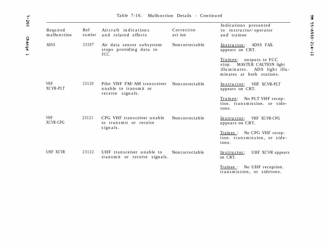
7-260
TM 55-6930-214-10
Table 7-16. Malfunction Details - Continued
Indications presentedRequired Ref Aircraft indications Corrective to instructor/operatormalfunction number and related effects act ion and trainee
ADSS 23107 Air data sensor subsystemstops providing data toFCC.
Noncorrectable Instructor: ADSS FAILappears on CRT.
Trainee: outputs to FCCstop. MASTER CAUTION lightilluminates. ADS light illu-minates at both stations.
VHFXCVR-PLT
VHFXCVR-CPG
UHF XCVR 23122
23120
23121
Pilot VHF FM/AM transceiverunable to transmit orreceive signals.
CPG VHF transceiver unableto transmit or receivesignals.
UHF transceiver unable totransmit or receive signals.
Noncorrectable Instructor: VHF XCVR-PLTappears on CRT.
Trainee: No PLT VHF recep-tion. transmission. or side-tone.
Noncorrectable Instructor: VHF XCVR-CPGappears on CRT.
Trainee : No CPG VHF recep-tion. transmission, or side-tone.
Noncorrectable Instructor: UHF XCVR appearson CRT.
Trainee : No UHF reception.transmission, or sidetone.
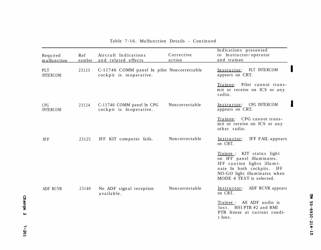
TM 55-6930-214-107-261
Table 7-16. Malfunction Details - Continued
Indications presentedRequired Ref Aircraft Indications Corrective to Instructor/operatormalfunction number and related effects action and trainee
PLTINTERCOM
23123
CPG 23124INTERCOM
IFF 23125
ADF RCVR 23140
C-11746 COMM panel In pilot Noncorrectable Instructor: PLT INTERCOMcockpit is inoperative. appears on CRT.
C-11746 COMM panel In CPG Noncorrectablecockpit is Inoperative.
IFF KIT computer fails. Noncorrectable
No ADF signal receptionavailable.
Noncorrectable
Trainee: Pilot cannot trans-mit or receive on ICS or anyradio.
Instructor: CPG INTERCOMappears on CRT.
Trainee: CPG cannot trans-mit or receive on ICS or anyother radio.
Instructor: IFF FAIL appearson CRT.
Trainee : KIT status lighton IFF panel illuminates.IFF caution lights illumi-nate In both cockpits. IFFNO-GO light illuminates whenMODE 4 TEST is selected.
Instructor: ADF RCVR appearson CRT.
Trainee : All ADF audio islost. HSI PTR #2 and RMIPTR freeze at current condi-t Ions.
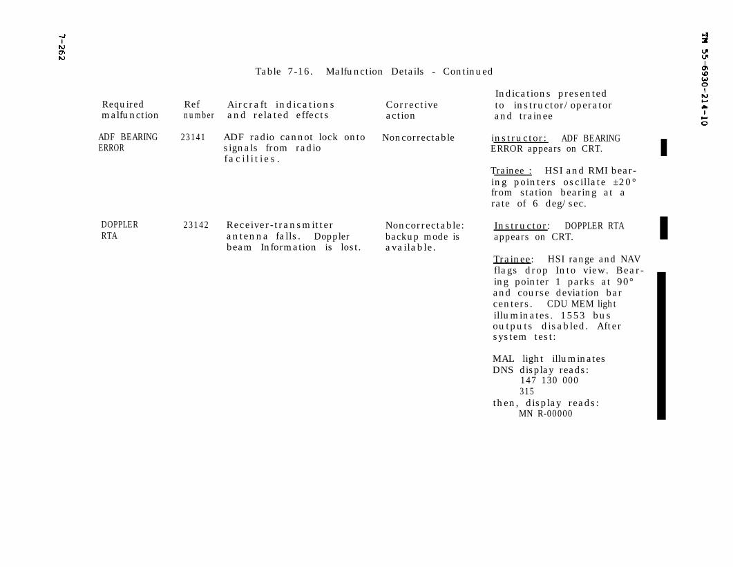
TM 55-6930-214-10
7-262
Table 7-16. Malfunction Details - Continued
Indications presentedRequired Ref Aircraft indications Correctivemalfunction
to instructor/operatornumber and related effects action and trainee
ADF BEARING 23141 ADF radio cannot lock onto Noncorrectable instructor: ADF BEARINGERROR signals from radio ERROR appears on CRT.
fac i l i t i es .Trainee : HSI and RMI bear-ing pointers oscillate ±20°from station bearing at arate of 6 deg/sec.
DOPPLERRTA
23142 Receiver-transmitter Noncorrectable:antenna falls. Doppler backup mode isbeam Information is lost. available.
Instructor: DOPPLER RTAappears on CRT.
Trainee: HSI range and NAVflags drop Into view. Bear-ing pointer 1 parks at 90°and course deviation barcenters. CDU MEM lightilluminates. 1553 busoutputs disabled. Aftersystem test:
MAL light illuminatesDNS display reads:
147 130 000315
then, display reads:MN R-00000
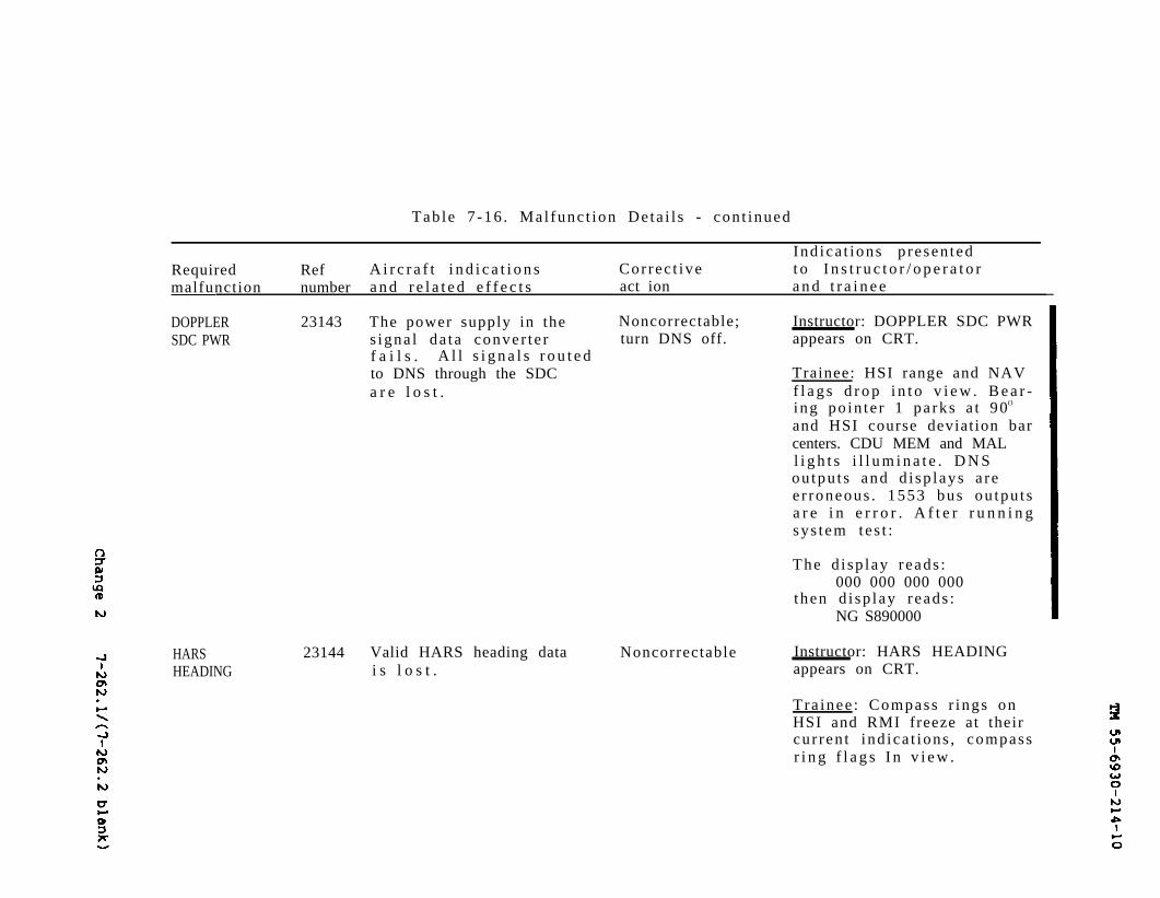
Change 2
7-262.1/(7-262.2 blank)
TM 55-6930-214-10
Table 7 -16 . Mal func t ion De ta i l s - con t inued
Ind ica t ions p resen tedRequired Ref A i r c r a f t i n d i c a t i o n s Cor rec t ive t o I n s t r u c t o r / o p e r a t o rmalfunction number a n d r e l a t e d e f f e c t s act ion a n d t r a i n e e
DOPPLERSDC PWR
23143 The power supply in the Noncorrectable; Instructor: DOPPLER SDC PWRsigna l da ta conver t e r turn DNS off. appears on CRT.f a i l s . A l l s i g n a l s r o u t e dto DNS through the SDC Trainee: HSI range and NAVa r e l o s t . f l a g s d r o p i n t o v i e w . B e a r -
ing po in te r 1 pa rks a t 90O
and HSI course deviat ion barcenters. CDU MEM and MALl i g h t s i l l u m i n a t e . D N Sou tpu t s and d i sp lays a ree r roneous . 1553 bus ou tpu t sa r e i n e r r o r . A f t e r r u n n i n gsys tem te s t :
The d i sp lay reads :000 000 000 000
then d i sp lay r eads :NG S890000
HARS 23144 Valid HARS heading data Noncorrectable Instructor: HARS HEADINGHEADING i s l o s t . appears on CRT.
Tra inee : Compass r ings onHSI and RMI freeze at theircu r ren t ind ica t ions , compassr i n g f l a g s I n v i e w .

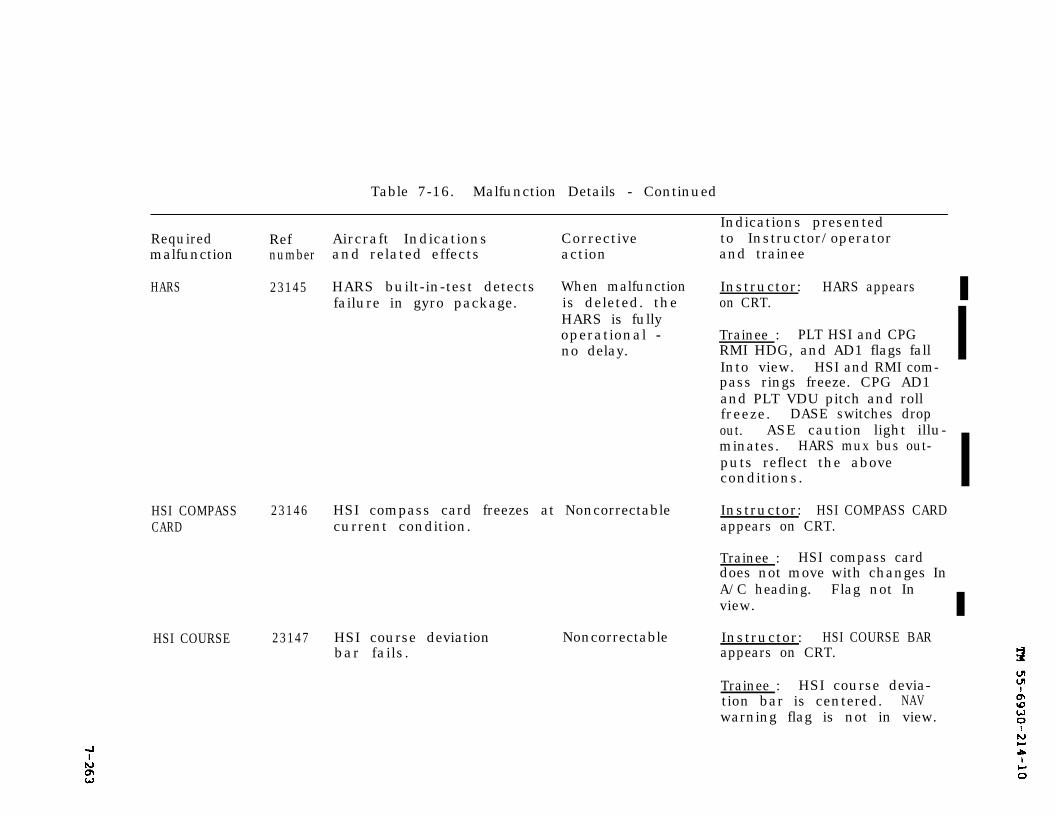
TM 55-6930-214-10
7263
Table 7-16. Malfunction Details - Continued
Indications presentedRequired Ref Aircraft Indications Corrective to Instructor/operatormalfunction number and related effects action and trainee
HARS 23145 HARS built-in-test detects When malfunction Instructor: HARS appearsfailure in gyro package. is deleted. the on CRT.
HARS is fullyoperational - Trainee : PLT HSI and CPGno delay. RMI HDG, and AD1 flags fall
Into view. HSI and RMI com-pass rings freeze. CPG AD1and PLT VDU pitch and rollfreeze. DASE switches dropout. ASE caution light illu-minates. HARS mux bus out-puts reflect the aboveconditions.
HSI COMPASS 23146 HSI compass card freezes at Noncorrectable Instructor: HSI COMPASS CARDCARD current condition. appears on CRT.
Trainee : HSI compass carddoes not move with changes InA/C heading. Flag not Inview.
HSI COURSE 23147 HSI course deviationbar fails.
Noncorrectable Instructor: HSI COURSE BARappears on CRT.
Trainee : HSI course devia-tion bar is centered. NAVwarning flag is not in view.
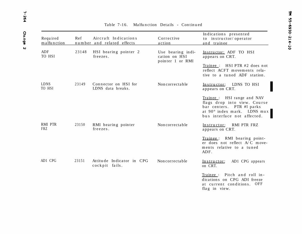
7-264 TM 55-6930-214-10
Table 7-16. Malfunction Details - Continued
Indications presentedRequired Ref Aircraft Indications Corrective to instructor/operatormalfunction number and related effects action and trainee
ADF 23148 HSI bearing pointer 2 Use bearing indi- Instructor: ADF TO HSITO HSI freezes. cation on HSI
pointer 1 or RMI
LDNS 23149 Connector on HSI forTO HSI LDNS data breaks.
RMI PTR 23150 RMI bearing pointerFRZ freezes.
AD1 CPG
Noncorrectable
Noncorrectable
23151 Attitude Indicator in CPG Noncorrectable Instructor: AD1 CPG appearscockpit fails. on CRT.
appears on CRT.
Trainee : HSI PTR #2 does notreflect ACFT movements rela-tive to a tuned ADF station.
Instructor: LDNS TO HSIappears on CRT.
Trainee : HSI range and NAVflags drop into view. Coursebar centers. PTR #l parksat 90° index mark. LDNS muxbus interface not affected.
Instructor: RMI PTR FRZappears on CRT.
Trainee : RMI bearing point-er does not reflect A/C move-ments relative to a tunedADF.
Trainee : Pitch and roll in-dications on CPG ADI freezeat current conditions. OFFflag in view.
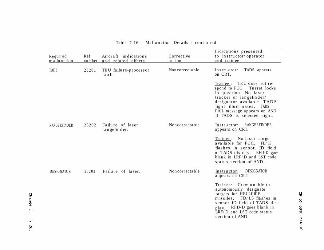
TM 55-69320-214-107-265
Table 7-16. Malfunction Details - continued
Indications presentedRequired Ref Aircraft indications Corrective to instructor/operatormalfunction number and related effects action and trainee
TADS 23201 TEU failure-processor Noncorrectable Instructor: TADS appearsfault. on CRT.
Trainee : TEU does not re-spond to FCC. Turret locksin position. No lasertracker or rangefinder/designator available. TADSlight illuminates. TADSFAIL message appears on ANDif TADS is selected sight.
RANGERFINDER 23202 Failure of laserrangefinder.
DESIGNATOR 23203 Failure of laser.
Noncorrectable
Noncorrectable
Instructor: RANGERFINDERappears on CRT.
Trainee: No laser rangeavailable for FCC. FD/LSflashes in sensor. ID fieldof TADS display. RFD-D goesblank in LRF/D and LST codestatus section of AND.
Instructor: DESIGNATORappears on CRT.
Trainee: Crew unable toautonomously designatetargets for HELLFIREmissiles. FD/LS flashes insensor ID field of TADS dis-play. RFD-D goes blank inLRF/D and LST code statussection of AND.
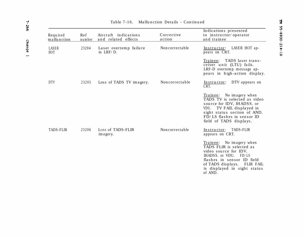
7-266TM 55-6930-214-10
Table 7-16. Malfunction Details - Continued
Indications presentedRequired Ref Aircraft indications Corrective to instructor/operatormalfunction number and related effects action and trainee
LASER 23204HOT
DTV 23205
Laser overtemp failurein LRF/D.
Noncorrectable Instructor: LASER HOT ap-pears on CRT.
Trainee: TADS laser trans-ceiver unit (LTU) fails.LRF-D overtemp message ap-pears in high-action display.
Loss of TADS TV imagery. Noncorrectable Instructor: DTV appears onCRT.
Trainee: No imagery whenTADS TV is selected as videosource for IDV, IHADSS. orVDU. TV FAIL displayed insight status section of AND.FD/LS flashes in sensor IDfield of TADS displays.
23206 LOSS of TADS-FLIRimagery.
Noncorrectable Instructor: TADS-FLIRappears on CRT.
Trainee: No imagery whenTADS FLIR is selected asvideo source for IDV.IHADSS. or VDU. FD/LSflashes in sensor ID fieldof TADS displays. FLIR FAILis displayed in sight statusof AND.
TADS-FLIR
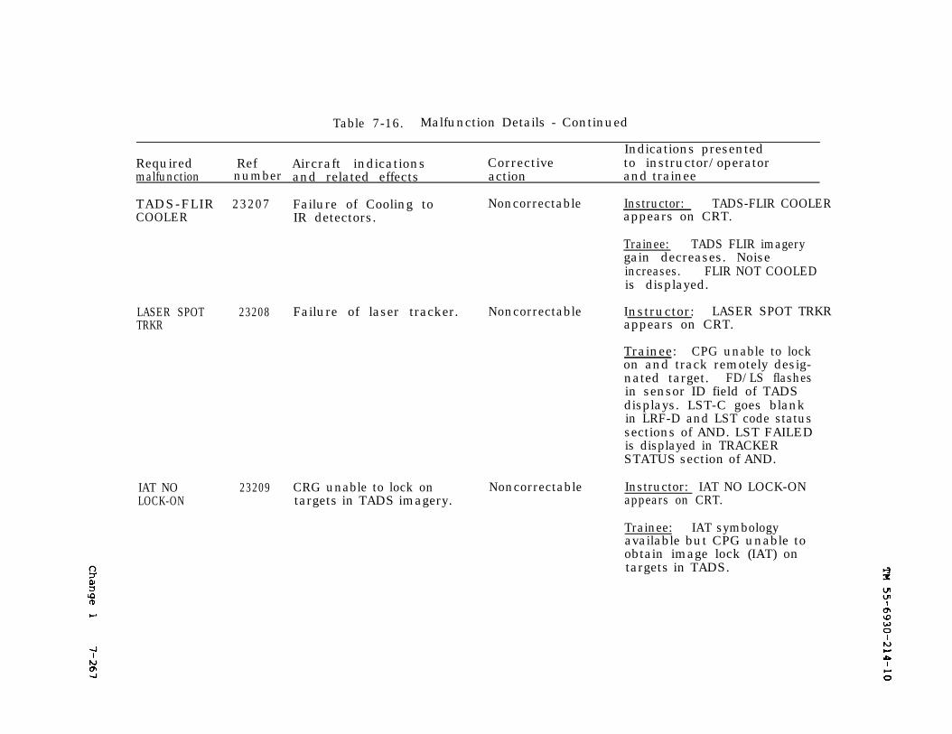
7-267
TM 55-6930-214-10
Table 7-16. Malfunction Details - Continued
Indications presentedRequired Ref Aircraft indications Corrective to instructor/operatormalfunction number and related effects action and trainee
TADS-FLIR 23207COOLER
LASER SPOT 23208 Failure of laser tracker. Noncorrectable Instructor: LASER SPOT TRKRTRKR appears on CRT.
IAT NO 23209LOCK-ON
Failure of Cooling toIR detectors.
Noncorrectable Instructor: TADS-FLIR COOLERappears on CRT.
Trainee: TADS FLIR imagerygain decreases. Noiseincreases. FLIR NOT COOLEDis displayed.
Trainee: CPG unable to lockon and track remotely desig-nated target. FD/LS flashesin sensor ID field of TADSdisplays. LST-C goes blankin LRF-D and LST code statussections of AND. LST FAILEDis displayed in TRACKERSTATUS section of AND.
CRG unable to lock on Noncorrectable Instructor: IAT NO LOCK-ONtargets in TADS imagery. appears on CRT.
Trainee: IAT symbologyavailable but CPG unable toobtain image lock (IAT) ontargets in TADS.
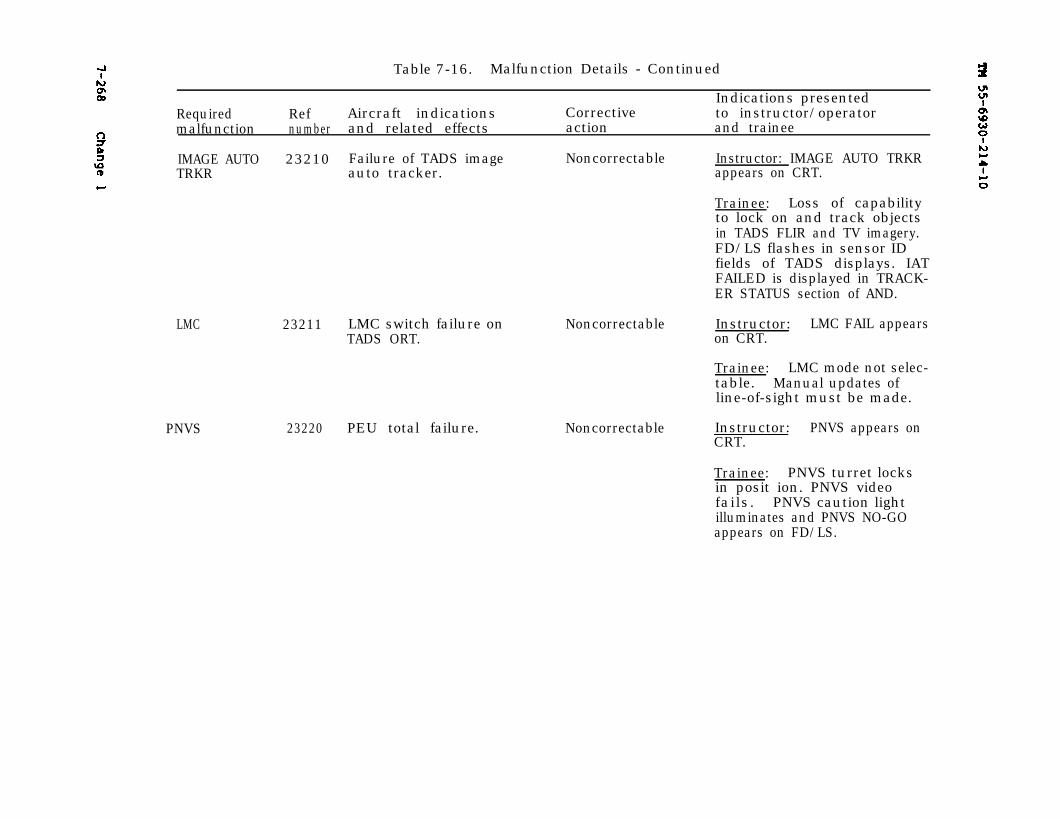
TM 55-6930-214-107-268
Table 7-16. Malfunction Details - Continued
Indications presentedRequired Ref Aircraft indications Corrective to instructor/operatormalfunction number and related effects action and trainee
IMAGE AUTO 23210 Failure of TADS imageTRKR auto tracker.
LMC 23211
PNVS 23220 PEU total failure.
Noncorrectable Instructor: IMAGE AUTO TRKRappears on CRT.
Trainee: Loss of capabilityto lock on and track objectsin TADS FLIR and TV imagery.FD/LS flashes in sensor IDfields of TADS displays. IATFAILED is displayed in TRACK-ER STATUS section of AND.
LMC switch failure onTADS ORT.
Noncorrectable Instructor: LMC FAIL appearson CRT.
Trainee: LMC mode not selec-table. Manual updates ofline-of-sight must be made.
Noncorrectable Instructor: PNVS appears onCRT.
Trainee: PNVS turret locksin posit ion. PNVS videofails. PNVS caution lightilluminates and PNVS NO-GOappears on FD/LS.
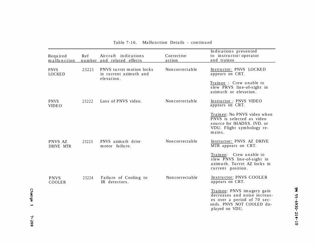
TM 55-6930-214-107-269
Table 7-16. Malfunction Details - continued
Indications presentedRequired Ref Aircraft indications Corrective to instructor/operatormalfunction number and related effects action and trainee
PNVSLOCKED
23221 PNVS turret motion locks Noncorrectable Instructor: PNVS LOCKEDin current azimuth and appears on CRT.elevation.
Trainee : Crew unable toslew PRVS line-of-sight inazimuth or elevation.
PNVSVIDEO
23222 Loss of PNVS video.
PNVS AZ 23223 PNVS azimuth driveDRIVE MTR motor failure.
PNVSCOOLER
23224 Failure of Cooling toIR detectors.
Noncorrectable
Noncorrectable
Instructor : PNVS VIDEOappears on CRT.
Trainee: No PNVS video whenPNVS is selected as videosource for IHADSS. IVD. orVDU. Flight symbology re-mains.
Instructor: PNVS AZ DRIVEMTR appears on CRT.
Trainee: Crew unable toslew PNVS line-of-sight inazimuth. Turret AZ locks incurrent position.
Noncorrectable Instructor: PNVS COOLERappears on CRT.
Trainee: PNVS imagery gaindecreases and noise increas-es over a period of 70 sec-onds. PNVS NOT COOLED dis-played on VDU.
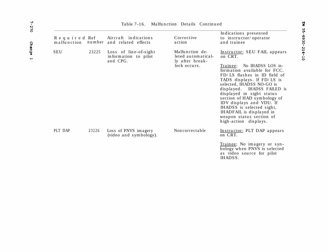
7-270 TM 55-6930-214-10
Table 7-16. Malfunction Details Continued
Indications presentedR e q u i r e d Ref Aircraft indications Corrective to instructor/operatormalfunction number and related effects action and trainee
SEU 23225 Loss of line-of-sight Malfunction de- Instructor: SEU FAIL appearsinformation to pilot leted automatical- on CRT.and CPG. ly after break-
lock occurs. Trainee: No IHADSS LOS in-formation available for FCC.FD/LS flashes in ID field ofTADS displays. If FD/LS isselected, IHADSS NO-GO isdisplayed. IHADSS FAILED isdisplayed in sight statussection of HAD symbology ofIDV displays and VDU. IfIHADSS is selected sight,IHADFAIL is displayed inweapon status section ofhigh-action displays.
PLT DAP 23226 Loss of PNVS imagery Noncorrectable Instructor: PLT DAP appears(video and symbology). on CRT.
Trainee: No imagery or syn-bology when PNVS is selectedas video source for pilotIHADSS.
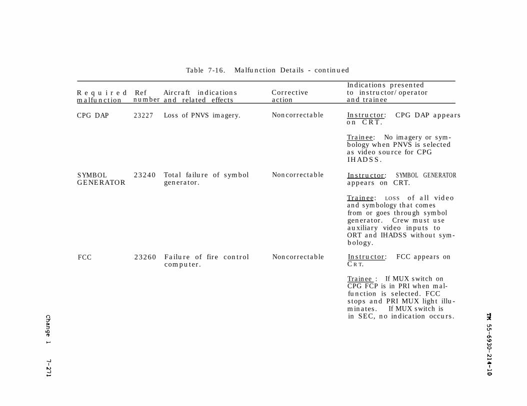
TM 55-6930-214-107-271
Table 7-16. Malfunction Details - continued
Indications presentedR e q u i r e d Ref Aircraft indications Corrective to instructor/operatormalfunction number and related effects action and trainee
CPG DAP 23227
SYMBOL 23240 Total failure of symbolGENERATOR generator.
FCC 23260
Loss of PNVS imagery. Noncorrectable Instructor: CPG DAP appearson CRT .
Trainee: No imagery or sym-bology when PNVS is selectedas video source for CPGIHADSS.
Noncorrectable Instructor: SYMBOL GENERATORappears on CRT.
Trainee: LOSS of all videoand symbology that comesfrom or goes through symbolgenerator. Crew must useauxiliary video inputs toORT and IHADSS without sym-bology.
Failure of fire controlcomputer.
Noncorrectable Instructor: FCC appears onCR T.
Trainee : If MUX switch onCPG FCP is in PRI when mal-function is selected. FCCstops and PRI MUX light illu-minates. If MUX switch isin SEC, no indication occurs.
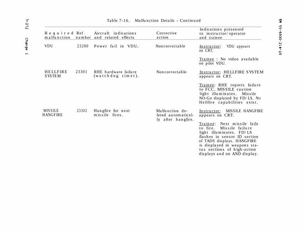
TM 55-6930-214-10
7-272
Table 7-16. Malfunction Details - Continued
Indications presentedR e q u i r e d Ref Aircraft indications Corrective to instructor/operatormalfunction number and related effects action and trainee
VDU 23280 Power fail in VDU. Noncorrectable Instructor: VDU appearson CRT.
Trainee : No video availableon pilot VDU.
HELLFIRE 23301 RHE hardware failureSYSTEM (watchdog t imer ) .
MISSILEHANGFIRE
23302 Hangfire for nextmissile fires.
Noncorrectable
Malfunction de-leted automatical-ly after hangfire.
Instructor: HELLFIRE SYSTEMappears on CRT.
Trainee: RHE reports failureto FCC. MISSILE cautionlight illuminates. MissileNO-Go displayed by FD/LS. NOHellfire capabilities exist.
Instructor: MISSILE HANGFIREappears on CRT.
Trainee: Next missile failsto fire. Missile failurelight illuminates. FD/LSflashes in sensor ID sectionof TADS displays. HANGFIREis displayed in weapons sta-tus sections of high-actiondisplays and on AND display.
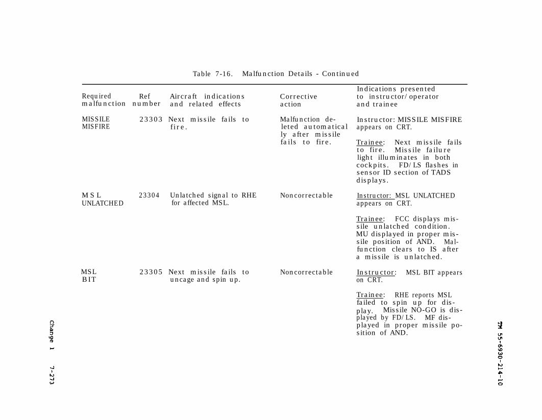
7-273 TM 55-6930-214-10
Table 7-16. Malfunction Details - Continued
Indications presentedRequired Ref Aircraft indications Corrective to instructor/operatormalfunction number and related effects action and trainee
MISSILEMISFIRE
23303 Next missile fails to Malfunction de- Instructor: MISSILE MISFIREfire. leted automatical appears on CRT.
ly after missilefails to fire. Trainee: Next missile fails
to fire. Missile failurelight illuminates in bothcockpits. FD/LS flashes insensor ID section of TADSdisplays.
M S L 23304 Unlatched signal to RHE NoncorrectableUNLATCHED for affected MSL.
MSLBIT
23305 Next missile fails touncage and spin up.
Noncorrectable
Instructor: MSL UNLATCHEDappears on CRT.
Trainee: FCC displays mis-sile unlatched condition.MU displayed in proper mis-sile position of AND. Mal-function clears to IS aftera missile is unlatched.
Instructor: MSL BIT appearson CRT.
Trainee: RHE reports MSLfailed to spin up for dis-play. Missile NO-GO is dis-played by FD/LS. MF dis-played in proper missile po-sition of AND.
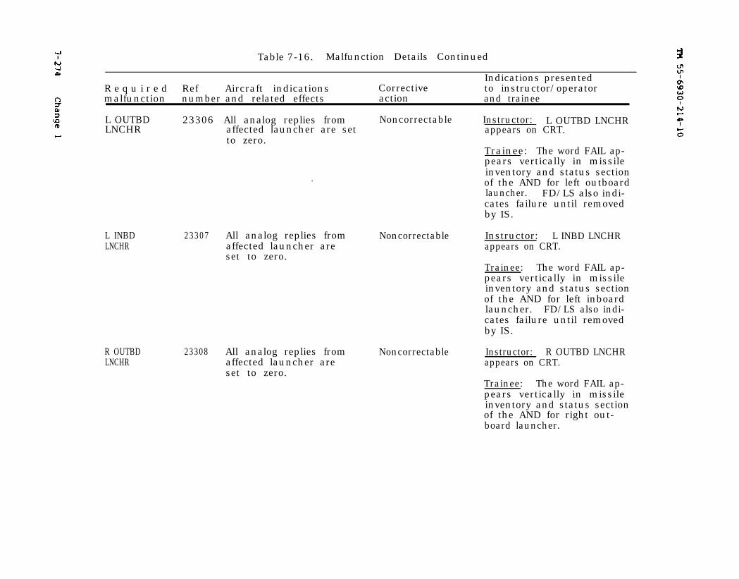
TM 55-6930-214-107-274
Table 7-16. Malfunction Details Continued
Indications presentedR e q u i r e d Ref Aircraft indications Corrective to instructor/operatormalfunction number and related effects action and trainee
L OUTBDLNCHR
23306 All analog replies from Noncorrectable Instructor: L OUTBD LNCHRaffected launcher are set appears on CRT.to zero.
Trainee: The word FAIL ap-pears vertically in missileinventory and status sectionof the AND for left outboardlauncher. FD/LS also indi-cates failure until removedby IS.
L INBDLNCHR
23307 All analog replies from Noncorrectableaffected launcher areset to zero.
R OUTBDLNCHR
23308 All analog replies from Noncorrectableaffected launcher areset to zero.
Instructor: L INBD LNCHRappears on CRT.
Trainee: The word FAIL ap-pears vertically in missileinventory and status sectionof the AND for left inboardlauncher. FD/LS also indi-cates failure until removedby IS.
Instructor: R OUTBD LNCHRappears on CRT.
Trainee: The word FAIL ap-pears vertically in missileinventory and status sectionof the AND for right out-board launcher.
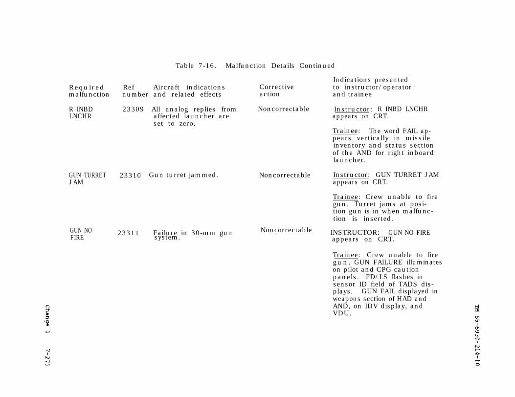
TM 55-6930-214-107-275
Table 7-16. Malfunction Details Continued
INSTRUCTOR: GUN NO FIREappears on CRT.
Indications presentedRequired Ref Aircraft indications Corrective to instructor/operatormalfunction number and related effects action and trainee
R INBDLNCHR
23309 All analog replies from Noncorrectable Instructor: R INBD LNCHRaffected launcher are appears on CRT.set to zero.
Trainee: The word FAIL ap-pears vertically in missileinventory and status sectionof the AND for right inboardlauncher.
GUN TURRET 23310 Gun turret jammed.JAM
GUN NO 23311 Failure in 30-mm gun NoncorrectableFIRE system.
Noncorrectable Instructor: GUN TURRET JAMappears on CRT.
Trainee: Crew unable to firegun. Turret jams at posi-tion gun is in when malfunc-tion is inserted.
Trainee: Crew unable to firegun. GUN FAILURE illuminateson pilot and CPG cautionpanels. FD/LS flashes insensor ID field of TADS dis-plays. GUN FAIL displayed inweapons section of HAD andAND, on IDV display, andVDU.
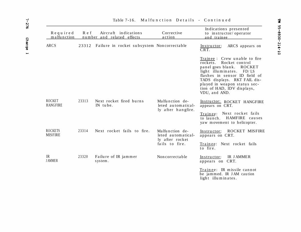
7-276 TM 5-6930-214-10
Table 7-16. M a l f u n c t i o n D e t a i l s - C o n t i n u e d
Indications presentedR e q u i r e d R e f Aircraft indications Corrective to instructor/operatormalfunction number and related effects action and trainee
ARCS 23312
ROCKET 23313 Next rocket fired burnsHANGFIRE IN tube.
ROCKETS 23314MISFIRE
IRJAMMER
Failure in rocket subsystem Noncorrectable
Malfunction de-leted automatical-ly after hangfire.
Next rocket fails to fire. Malfunction de-leted automatical-ly after rocketfails to fire.
23320 Failure of IR jammersystem.
Noncorrectable
Instructor: ARCS appears onCRT.
Trainee : Crew unable to firerockets. Rocket controlpanel goes blank. ROCKETlight illuminates. FD/LSflashes in sensor ID field ofTADS displays. RKT FAIL dis-played in weapon status sec-tion of HAD, IDV displays,VDU, and AND.
Instructor: ROCKET HANGFIREappears on CRT.
Trainee: Next rocket failsto launch. HAMFIRE causesyaw movement to helicopter.
Instructor: ROCKET MISFIREappears on CRT.
Trainee: Next rocket failsto fire.
Instructor: IR JAMMERappears on CRT.
Trainee: IR missile cannotbe jammed. IR JAM cautionlight illuminates.
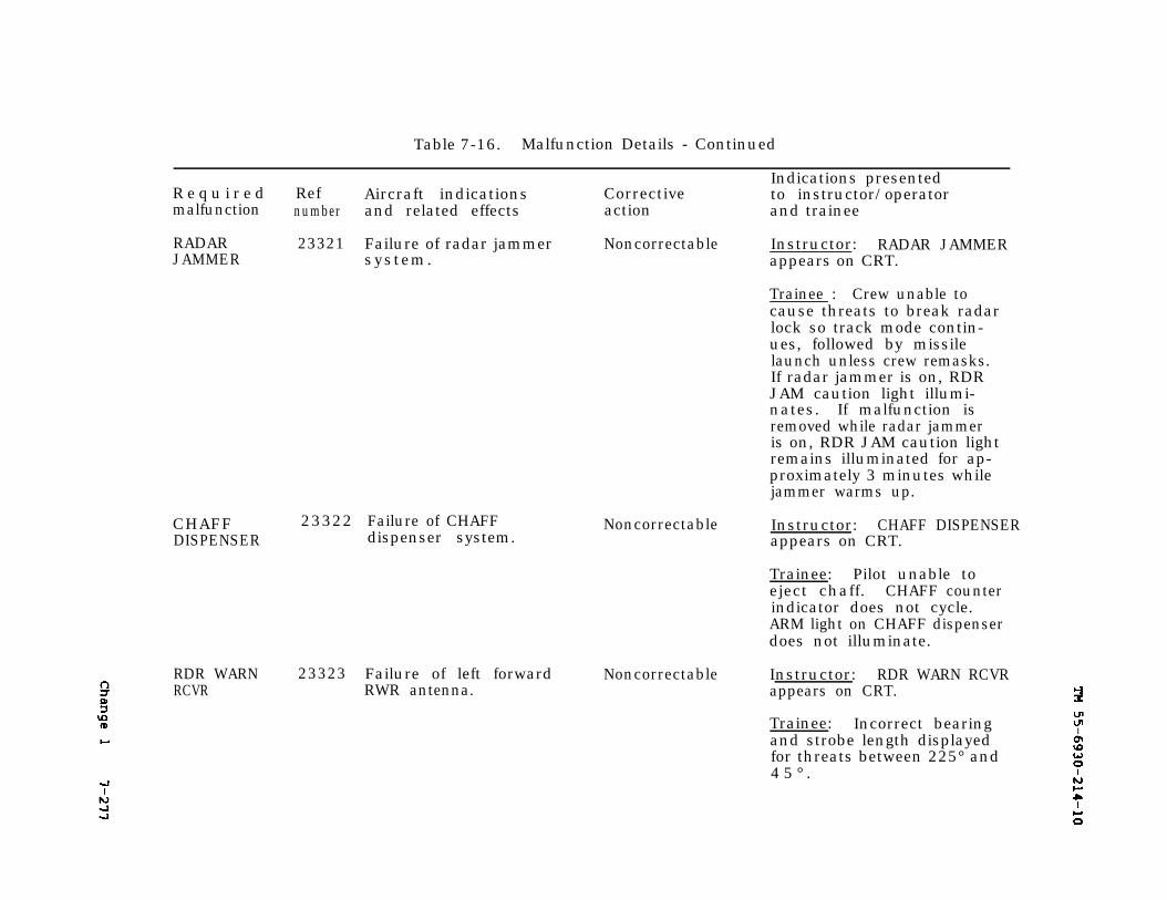
7-277TM 55-6930-214-10
Table 7-16. Malfunction Details - Continued
Indications presentedR e q u i r e d Ref Aircraft indications Corrective to instructor/operatormalfunction number and related effects action and trainee
RADAR 23321 Failure of radar jammer Noncorrectable Instructor: RADAR JAMMERJAMMER system. appears on CRT.
Trainee : Crew unable tocause threats to break radarlock so track mode contin-ues, followed by missilelaunch unless crew remasks.If radar jammer is on, RDRJAM caution light illumi-nates. If malfunction isremoved while radar jammeris on, RDR JAM caution lightremains illuminated for ap-proximately 3 minutes whilejammer warms up.
CHAFFDISPENSER
23322 Failure of CHAFFdispenser system.
Noncorrectable Instructor: CHAFF DISPENSERappears on CRT.
Trainee: Pilot unable toeject chaff. CHAFF counterindicator does not cycle.ARM light on CHAFF dispenserdoes not illuminate.
RDR WARNRCVR
23323 Failure of left forward Noncorrectable Instructor: RDR WARN RCVRRWR antenna. appears on CRT.
Trainee: Incorrect bearingand strobe length displayedfor threats between 225° and4 5 ° .
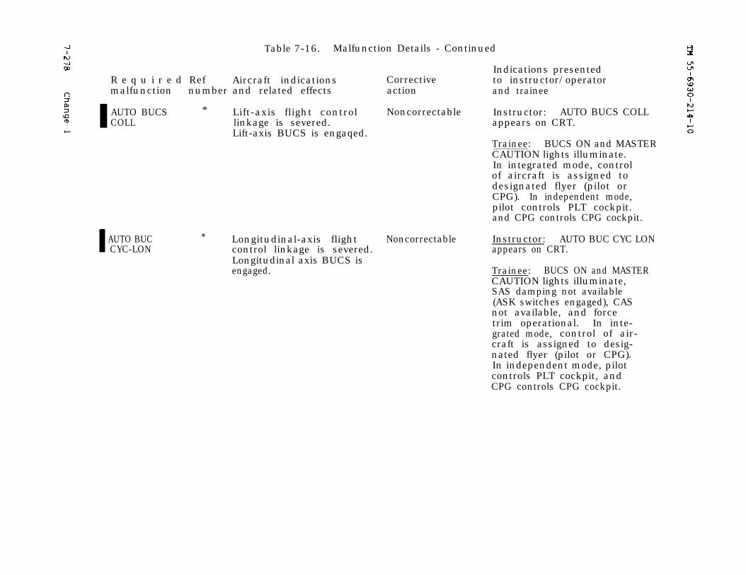
TM 55-6930-214-107-278
Table 7-16. Malfunction Details - Continued
Indications presentedR e q u i r e d Ref Aircraft indications Corrective to instructor/operatormalfunction number and related effects action and trainee
AUTO BUCS * Lift-axis flight control Noncorrectable Instructor: AUTO BUCS COLLCOLL linkage is severed. appears on CRT.
Lift-axis BUCS is engaqed.Trainee: BUCS ON and MASTERCAUTION lights illuminate.In integrated mode, controlof aircraft is assigned todesignated flyer (pilot orCPG). In independent mode,pilot controls PLT cockpit.and CPG controls CPG cockpit.
AUTO BUCCYC-LON
* Longitudinal-axis flight Noncorrectable Instructor: AUTO BUC CYC LONcontrol linkage is severed. appears on CRT.Longitudinal axis BUCS isengaged. Trainee: BUCS ON and MASTER
CAUTION lights illuminate,SAS damping not available(ASK switches engaged), CASnot available, and forcetrim operational. In inte-grated mode, control of air-craft is assigned to desig-nated flyer (pilot or CPG).In independent mode, pilotcontrols PLT cockpit, andCPG controls CPG cockpit.
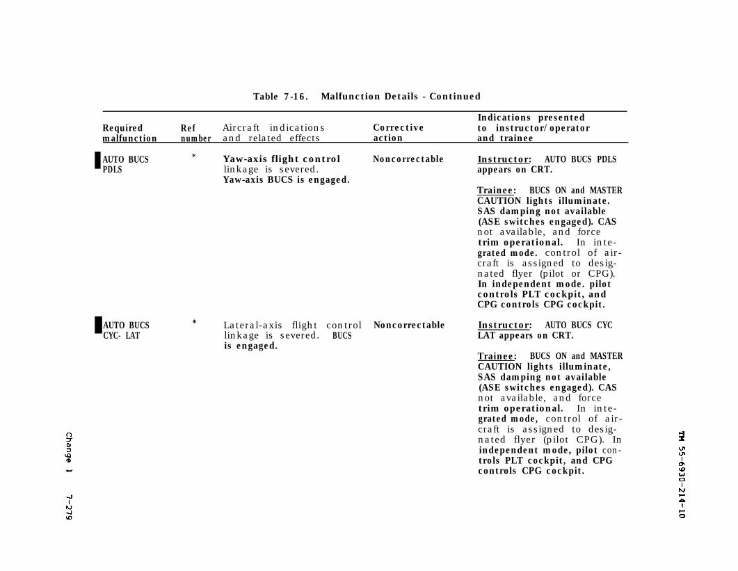
TM 55-6930-214-107-279
Table 7-16. Malfunction Details - Continued
Indications presentedRequired Ref Aircraft indications Corrective to instructor/operatormalfunction number and related effects action and trainee
AUTO BUCS * Yaw-axis flight control Noncorrectable Instructor: AUTO BUCS PDLSPDLS linkage is severed. appears on CRT.
Yaw-axis BUCS is engaged.Trainee: BUCS ON and MASTERCAUTION lights illuminate.SAS damping not available(ASE switches engaged). CASnot available, and forcetrim operational. In inte-grated mode. control of air-craft is assigned to desig-nated flyer (pilot or CPG).In independent mode. pilotcontrols PLT cockpit, andCPG controls CPG cockpit.
AUTO BUCS * Lateral-axis flight control Noncorrectable Instructor: AUTO BUCS CYCCYC- LAT linkage is severed. BUCS LAT appears on CRT.
is engaged.Trainee: BUCS ON and MASTERCAUTION lights illuminate,SAS damping not available(ASE switches engaged). CASnot available, and forcetrim operational. In inte-grated mode, control of air-craft is assigned to desig-nated flyer (pilot CPG). Inindependent mode, pilot con-trols PLT cockpit, and CPGcontrols CPG cockpit.
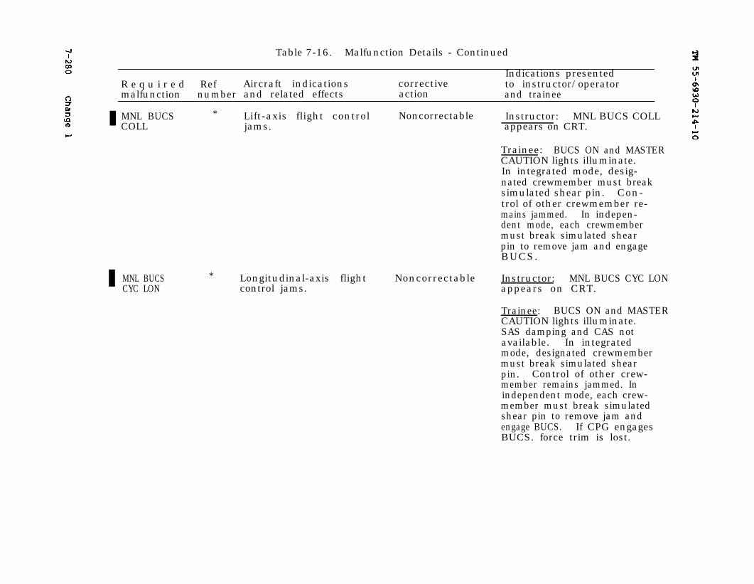
7-280
TM 55-6930-214-10
Table 7-16. Malfunction Details - Continued
Indications presentedR e q u i r e d Ref Aircraft indications corrective to instructor/operatormalfunction number and related effects action and trainee
MNL BUCS * Lift-axis flight control Noncorrectable Instructor: MNL BUCS COLLCOLL jams. appears on CRT.
Trainee: BUCS ON and MASTERCAUTION lights illuminate.In integrated mode, desig-nated crewmember must breaksimulated shear pin. Con-trol of other crewmember re-mains jammed. In indepen-dent mode, each crewmembermust break simulated shearpin to remove jam and engageBUCS.
MNL BUCSCYC LON
* Longitudinal-axis flight Noncorrectable Instructor: MNL BUCS CYC LONcontrol jams. appears on CRT.
Trainee: BUCS ON and MASTERCAUTION lights illuminate.SAS damping and CAS notavailable. In integratedmode, designated crewmembermust break simulated shearpin. Control of other crew-member remains jammed. Inindependent mode, each crew-member must break simulatedshear pin to remove jam andengage BUCS. If CPG engagesBUCS. force trim is lost.
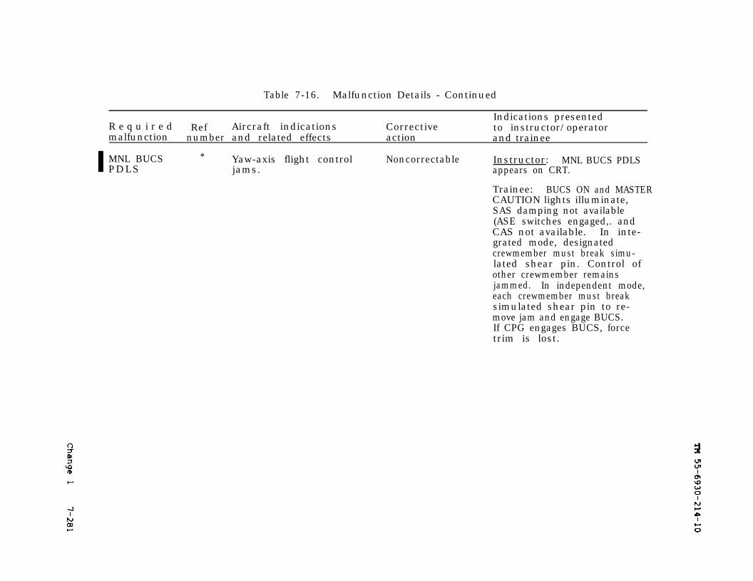
7-281 TM 55-6930-214-10
Table 7-16. Malfunction Details - Continued
R e q u i r e d RefIndications presented
Aircraft indications Correctivemalfunction number
to instructor/operatorand related effects action and trainee
MNL BUCS * Yaw-axis flight control Noncorrectable Instructor: MNL BUCS PDLSPDLS jams. appears on CRT.
Trainee: BUCS ON and MASTERCAUTION lights illuminate,SAS damping not available(ASE switches engaged,. andCAS not available. In inte-grated mode, designatedcrewmember must break simu-lated shear pin. Control ofother crewmember remainsjammed. In independent mode,each crewmember must breaksimulated shear pin to re-move jam and engage BUCS.If CPG engages BUCS, forcetrim is lost.
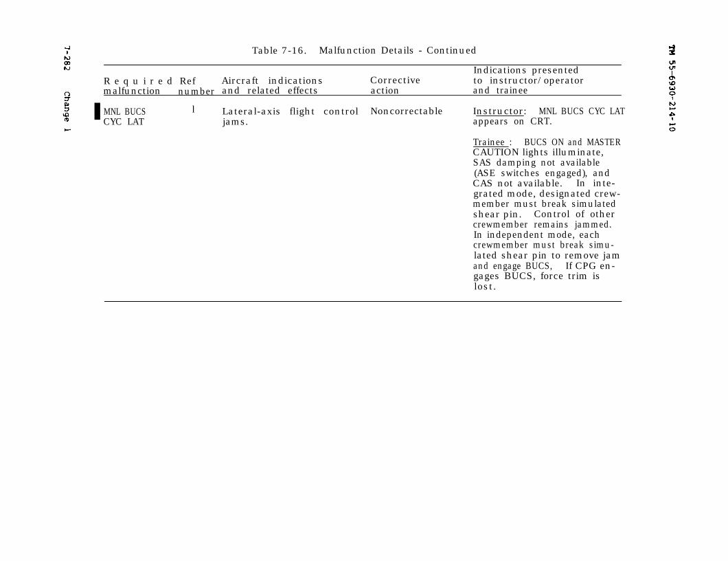
TM 55-6930-214-107-282
Table 7-16. Malfunction Details - Continued
Indications presentedR e q u i r e d Ref Aircraft indications Corrective to instructor/operatormalfunction number and related effects action and trainee
MNL BUCS l Lateral-axis flight control Noncorrectable Instructor: MNL BUCS CYC LATCYC LAT jams. appears on CRT.
Trainee : BUCS ON and MASTERCAUTION lights illuminate,SAS damping not available(ASE switches engaged), andCAS not available. In inte-grated mode, designated crew-member must break simulatedshear pin. Control of othercrewmember remains jammed.In independent mode, eachcrewmember must break simu-lated shear pin to remove jamand engage BUCS, If CPG en-gages BUCS, force trim islost.
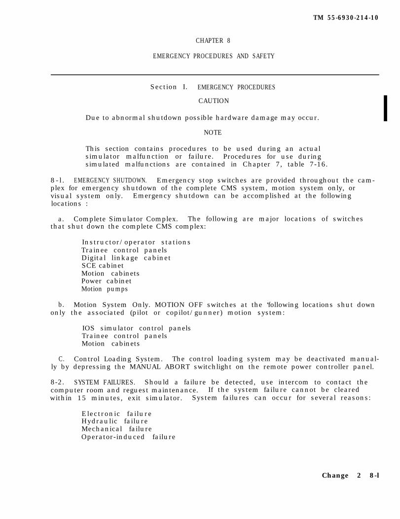
TM 55-6930-214-10
CHAPTER 8
EMERGENCY PROCEDURES AND SAFETY
Section I. EMERGENCY PROCEDURES
CAUTION
Due to abnormal shutdown possible hardware damage may occur.
NOTE
This section contains procedures to be used during an actualsimulator malfunction or failure. Procedures for use duringsimulated malfunctions are contained in Chapter 7, table 7-16.
8-l . EMERGENCY SHUTDOWN. Emergency stop switches are provided throughout the cam-plex for emergency shutdown of the complete CMS system, motion system only, orvisual system only. Emergency shutdown can be accomplished at the followinglocations :
a. Complete Simulator Complex. The following are major locations of switchesthat shut down the complete CMS complex:
Instructor/operator stationsTrainee control panelsDigital linkage cabinetSCE cabinetMotion cabinetsPower cabinetMotion pumps
b. Motion System Only. MOTION OFF switches at the ‘following locations shut downonly the associated (pilot or copilot/gunner) motion system:
IOS simulator control panelsTrainee control panelsMotion cabinets
C. Control Loading System. The control loading system may be deactivated manual-ly by depressing the MANUAL ABORT switchlight on the remote power controller panel.
8-2. SYSTEM FAILURES. Should a failure be detected, use intercom to contact thecomputer room and reguest maintenance. If the system failure cannot be clearedwithin 15 minutes, exit simulator. System failures can occur for several reasons:
Electronic failureHydraulic failureMechanical failureOperator-induced failure
Change 2 8-l

TM 55-6930-214-10
WARNING
Care should be exercised when exiting the simulator during powerfailure. The boarding ramp may fail to deploy.
8-3. FACILITY POWER FAILURE. Loss of facility power results in shutdown of theentire CMS complex.the following:
The total simulator becomes deactivated with the exception of
Emergency lightingFire detection systemRampTelephone intercom
8-2 Change 2
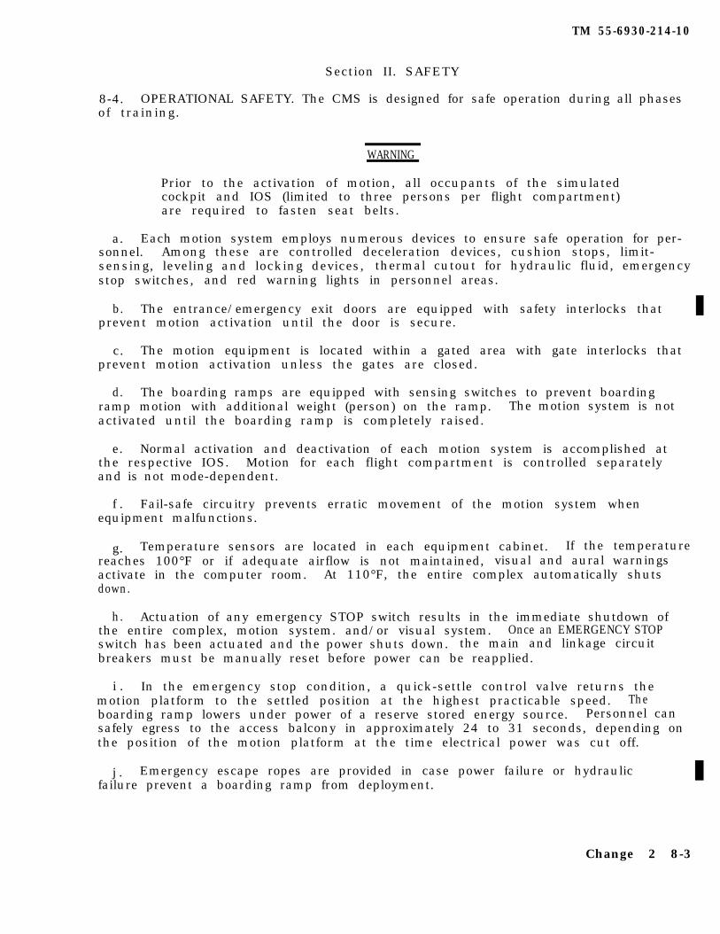
TM 55-6930-214-10
Section II. SAFETY
8-4. OPERATIONAL SAFETY. The CMS is designed for safe operation during all phasesof training.
WARNING
Prior to the activation of motion, all occupants of the simulatedcockpit and IOS (limited to three persons per flight compartment)are required to fasten seat belts.
a. Each motion system employs numerous devices to ensure safe operation for per-sonnel. Among these are controlled deceleration devices, cushion stops, limit-sensing, leveling and locking devices, thermal cutout for hydraulic fluid, emergencystop switches, and red warning lights in personnel areas.
b. The entrance/emergency exit doors are equipped with safety interlocks thatprevent motion activation until the door is secure.
c. The motion equipment is located within a gated area with gate interlocks thatprevent motion activation unless the gates are closed.
d. The boarding ramps are equipped with sensing switches to prevent boardingramp motion with additional weight (person) on the ramp. The motion system is notactivated until the boarding ramp is completely raised.
e. Normal activation and deactivation of each motion system is accomplished atthe respective IOS. Motion for each flight compartment is controlled separatelyand is not mode-dependent.
f . Fail-safe circuitry prevents erratic movement of the motion system whenequipment malfunctions.
g. Temperature sensors are located in each equipment cabinet. If the temperaturereaches 100°F or if adequate airflow is not maintained, visual and aural warningsactivate in the computer room. At 110°F, the entire complex automatically shutsdown.
h. Actuation of any emergency STOP switch results in the immediate shutdown ofthe entire complex, motion system. and/or visual system. Once an EMERGENCY STOPswitch has been actuated and the power shuts down. the main and linkage circuitbreakers must be manually reset before power can be reapplied.
i . In the emergency stop condition, a quick-settle control valve returns themotion platform to the settled position at the highest practicable speed. Theboarding ramp lowers under power of a reserve stored energy source. Personnel cansafely egress to the access balcony in approximately 24 to 31 seconds, depending onthe position of the motion platform at the time electrical power was cut off.
j . Emergency escape ropes are provided in case power failure or hydraulicfailure prevent a boarding ramp from deployment.
Change 2 8-3

TM 55-6930-214-10
WARNING
Do not discharge a CF3BR fire extinguisher In the confinedcockpit.
k. Five fire extinguishers are located In central areas of the CMS complex. oneIn the computer room, two in the simulator room, and one In each pump room. Twoother fire extinguishers are located in the flight simulator compartments, forminga part of the normal cockpit equipment. The fire extinguishers aremonobromotrifuloromethane (CF3BR). These fire extinguishers are caustic Innature and can seriously damage sensitive electronic equipment not already damagedby fire.
l . The visual system safety system Includes an emergency egress switch in thecockpit. Actuation of the switch causes the right window viewing head to swingaway from the cockpit to allow egress.
m. In the event an anomaly called “Computer Runaway” occurs, PROBLEM FREEZE,MOTION OFF, and all communications fall to operate. The recommended procedure tohalt the motion system Is to activate the RIGHT VISUAL DISPLAY CONTROL switch Inthe trainee station. This triggers the motion system microswitch and shuts downmotion.
n. When the ownship takes a direct weapons hit, there Is a violent reaction fromthe motion system. The pilot station receives a 10- to 15-degree pitch-up cue and700- to 900-knot side wind effect. The CPG station receives only the side windeffects to prevent Injury when the CPG’s face is lowered toward the cockpit display.
o. An abort, or safety, circuit Is provided on card 4 of each axis to protectagainst excessive control motion due to an abnormal transient Input or a hard-overcondition resulting from a malfunction. The circuit senses control acceleration(derivative of velocity) and switches a high resistance in series with the servovalve torque motor when excessive control acceleration is present. Since thiscircuit interfaces with a solenoid-operated dump valve via the start-stop Interlockcontrols (SSIC), hydraulic pressure to the control loader actuators is also dumpedwhen excessive acceleration Is sensed. The control loading system can also beaborted manually by depressing the MANUAL ABORT pushbutton on the remote powercontroller panel.
8-4 Change 2
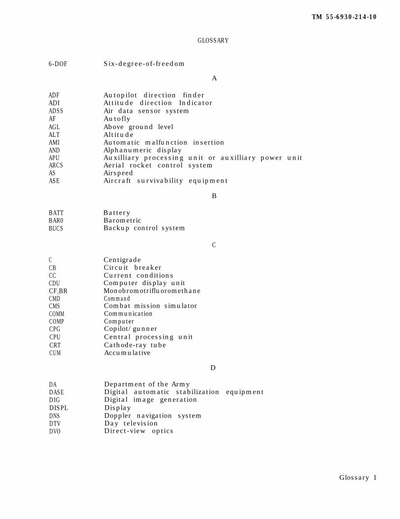
TM 55-6930-214-10
GLOSSARY
Six-degree-of-freedom6-DOF
A
Autopilot direction finderAttitude direction IndicatorAir data sensor systemAutoflyAbove ground levelAltitudeAutomatic malfunction insertionAlphanumeric displayAuxilliary processing unit or auxilliary power unitAerial rocket control systemAirspeedAircraft survivability equipment
ADFADIADSSAFAGLALTAMIANDAPUARCSASASE
B
BatteryBarometricBackup control system
BATTBAR0BUCS
C
CentigradeCircuit breakerCurrent conditionsComputer display unitMonobromotrifluoromethaneCommandCombat mission simulatorCommunicationComputerCopilot/gunnerCentral processing unitCathode-ray tubeAccumulative
CCBCCCDUCF3BRCMDCMSCOMMCOMPCPGCPUCRTCUM
D
Department of the ArmyDigital automatic stabilization equipmentDigital image generationDisplayDoppler navigation systemDay televisionDirect-view optics
DADASEDIGDISPLDNSDTVDVO
Glossary 1
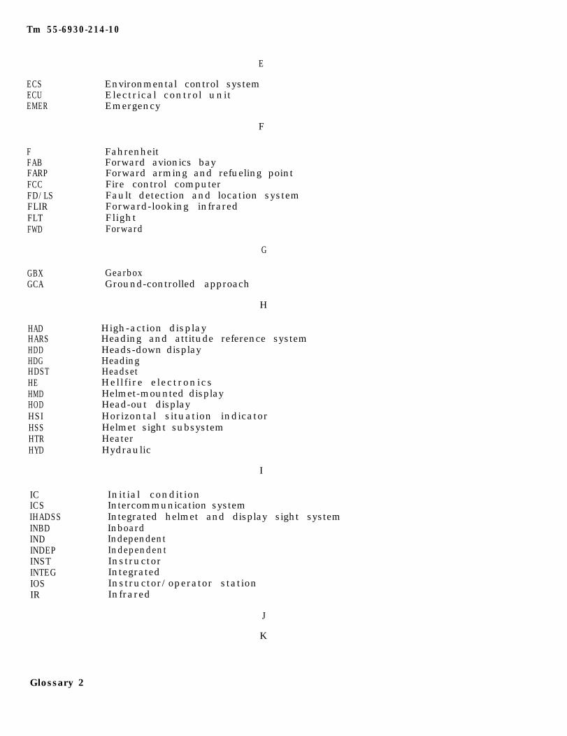
Tm 55-6930-214-10
E
ECS Environmental control systemECU Electrical control unitEMER Emergency
F
FFABFARPFCCFD/LSFLIRFLTFWD
G
GBXGCA
H
HADHARSHDDHDGHDSTHEHMDHODHSIHSSHTRHYD
I
ICICSIHADSSINBDINDINDEPINSTINTEGIOSIR
FahrenheitForward avionics bayForward arming and refueling pointFire control computerFault detection and location systemForward-looking infraredFlightForward
GearboxGround-controlled approach
High-action displayHeading and attitude reference systemHeads-down displayHeadingHeadsetHellfire electronicsHelmet-mounted displayHead-out displayHorizontal situation indicatorHelmet sight subsystemHeaterHydraulic
Initial conditionIntercommunication systemIntegrated helmet and display sight systemInboardIndependentIndependentInstructorIntegratedInstructor/operator stationInfrared
J
K
Glossary 2
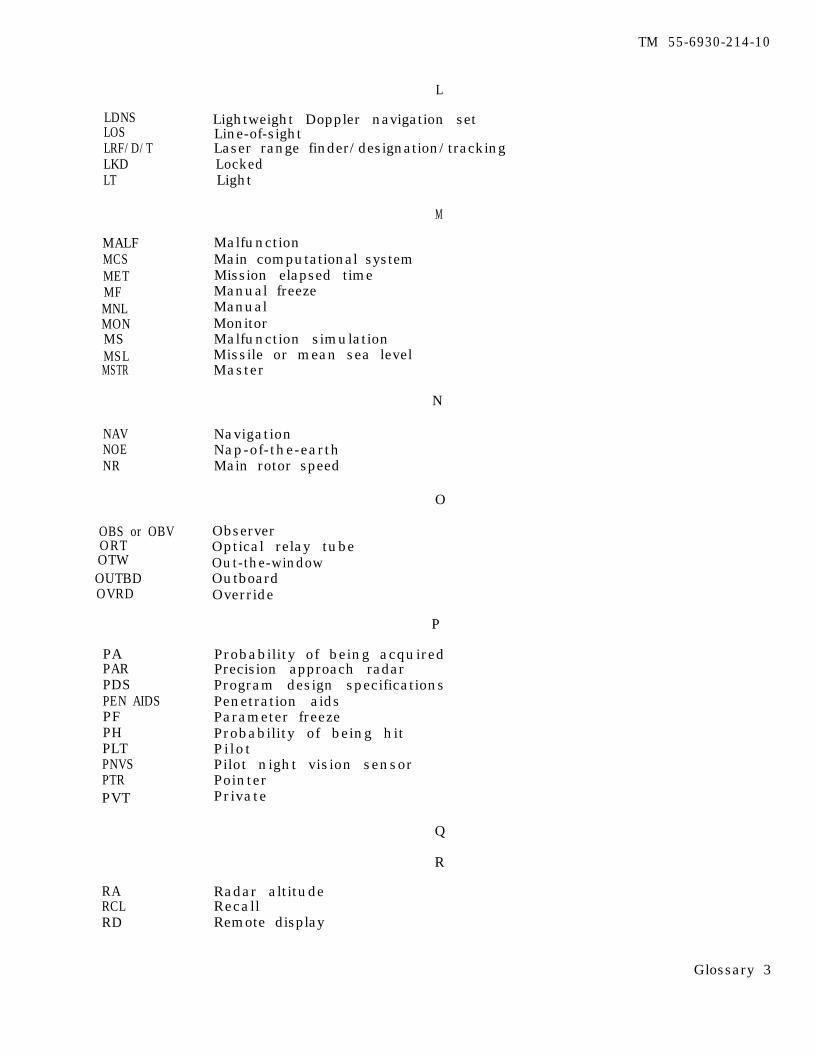
TM 55-6930-214-10
L
LDNS Lightweight Doppler navigation setLOS Line-of-sightLRF/D/T Laser range finder/designation/trackingLKD LockedLT Light
M
MALFMCSMETMFMNLMONMSMSLMSTR
MalfunctionMain computational systemMission elapsed timeManual freezeManualMonitorMalfunction simulationMissile or mean sea levelMaster
N
NAVNOENR
NavigationNap-of-the-earthMain rotor speed
O
OBS or OBV ObserverORT Optical relay tubeOTW Out-the-windowOUTBD OutboardOVRD Override
PAPARPDSPEN AIDSPFPHPLTPNVSPTR
RARCLRD
Probability of being acquiredPrecision approach radarProgram design specificationsPenetration aidsParameter freezeProbability of being hitPilotPilot night vision sensorPointerPrivate
Q
R
Radar altitudeRecallRemote display
Glossary 3
P
PVT
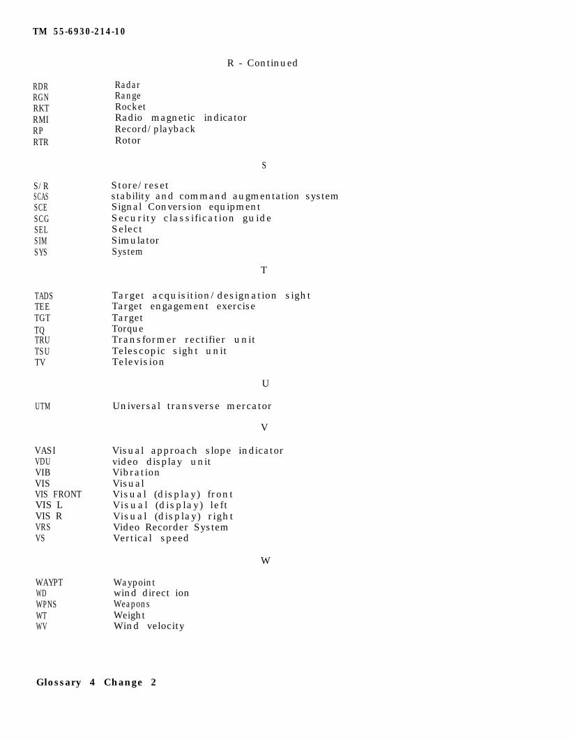
TM 55-6930-214-10
R - Continued
RDRRGNRKTRMIRPRTR
S/RSCASSCESCGSELSIMSYS
T
TADSTEETGTTQTRUTSUTV
U
UTM
V
VASIVDUVIBVISVIS FRONTVIS LVIS RVRSVS
W
WAYPTWDWPNSWTWV
RadarRangeRocketRadio magnetic indicatorRecord/playbackRotor
S
Store/resetstability and command augmentation systemSignal Conversion equipmentSecurity classification guideSelectSimulatorSystem
Target acquisition/designation sightTarget engagement exerciseTargetTorqueTransformer rectifier unitTelescopic sight unitTelevision
Universal transverse mercator
Visual approach slope indicatorvideo display unitVibrationVisualVisual (display) frontVisual (display) leftVisual (display) rightVideo Recorder SystemVertical speed
Waypointwind direct ionWeaponsWeightWind velocity
Glossary 4 Change 2

TM 55-6930-214-10
x
x-cXMITXMSN
Cross-countryTransmitTransmission
Y
Z
Glossary 5/(Glossary 6 blank)

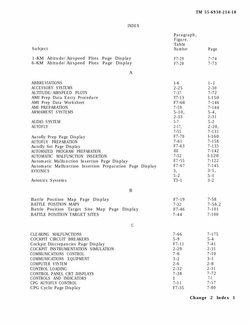
INDEX
Subject
1-KM Altitude/Airspeed Plots Page Display F7-29 7-746-KM Altitude/Airspeed Plots Page Display F7-28 7-73
A
ABBREVIATIONSACCESSORY SYSTEMSALTITUDE/AIRSPEED PLOTSAMI Prep Data Entry ProcedureAMI Prep Data WorksheetAMI PREPARATIONARMAMENT SYSTEMS
AUDIO SYSTEMAUTOFLY
Autofly Prep Page DisplayAUTOFLY PREPARATIONAutofly Set Page DisplayAUTOMATED PROGRAM PREPARATIONAUTOMATIC MALFUNCTION INSERTIONAutomatic Malfunction Insertion Page DisplayAutomatic Malfunction Insertion Preparation Page DisplayAVIONICS
Avionics Systems
B
Battle Position Map Page Display F7-19 7-58BATTLE POSITION MAPS 7-32 7-56.2Battle Position Target Site Map Page Display F7-46 7-101BATTLE POSITION TARGET SITES 7-44 7-100
C
CLEARING MALFUNCTIONS 7-66 7-175COCKPIT CIRCUIT BREAKERS 5-9 5-4Cockpit Discrepancies Page Display F7-11 7-41COCKPIT INSTRUMENTATION SIMULATION 2-29 2-31COMMUNICATIONS CONTROL 7-6 7-10COMMUNICATIONS EQUIPMENT 3-2 3-lCOMPUTER SYSTEM 2-6 2-8CONTROL LOADING 2-32 2-31CONTROL PANEL CRT DISPLAYS 7-38 7-72CONTROLS AND INDICATORS I 7-1CPG AUTOFLY CONTROL 7-11 7-17CPG Cyclic Page Display F7-35 7-80
Paragraph,Figure.TableNumber
l-6 l - l2-25 2-307-37 7-72T7-13 l-150F7-68 7-1467-59 7-1445-10, 5-4,2-33 2-315-7 5-22-17, 2-20,7-55 7-131F7-70 l-1607-61 7-158F7-63 7-135III 7-1427-52 l-120F7-55 7-122F7-67 7-1453, 3-1,5-2 5-lT3-1 3-2
TM 55-6930-214-10
Page
Change 2 Index 1
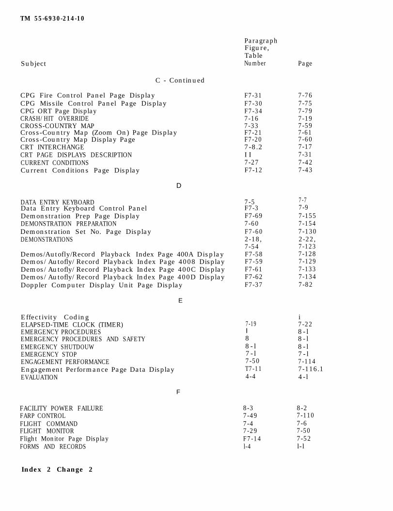
TM 55-6930-214-10
ParagraphFigure,TableNumberSubject Page
C - Continued
CPG Fire Control Panel Page DisplayCPG Missile Control Panel Page DisplayCPG ORT Page DisplayCRASH/HIT OVERRIDECROSS-COUNTRY MAPCross-Country Map (Zoom On) Page DisplayCross-Country Map Display PageCRT INTERCHANGECRT PAGE DISPLAYS DESCRIPTIONCURRENT CONDITIONSCurrent Conditions Page Display
F7-31 7-76F7-30 7-75F7-34 7-797-16 7-197-33 7-59F7-21 7-61F7-20 7-607-8.2 7-17I I 7-317-27 7-42F7-12 7-43
D
DATA ENTRY KEYBOARDData Entry Keyboard Control PanelDemonstration Prep Page DisplayDEMONSTRATION PREPARATIONDemonstration Set No. Page DisplayDEMONSTRATIONS
7-5F7-3F7-697-60F7-602-18,7-54F7-58F7-59F7-61F7-62F7-37
7-77-97-1557-1547-1302-22,7-1237-1287-1297-1337-1347-82
Demos/Autofly/Record Playback Index Page 400A DisplayDemos/Autofly/Record Playback Index Page 4008 DisplayDemos/Autofly/Record Playback Index Page 400C DisplayDemos/Autofly/Record Playback Index Page 400D DisplayDoppler Computer Display Unit Page Display
E
Effectivity CodingELAPSED-TIME CLOCK (TIMER)EMERGENCY PROCEDURESEMERGENCY PROCEDURES AND SAFETYEMERGENCY SHUTDOUWEMERGENCY STOPENGAGEMENT PERFORMANCEEngagement Performance Page Data DisplayEVALUATION
I
i7-228-l8-l8-l7-l7-1147-116.14-l
7-19
88-l7-l7-50T7-114-4
F
FACILITY POWER FAILURE 8-3 8-2FARP CONTROL 7-49 7-110FLIGHT COMMAND 7-4 7-6FLIGHT MONITOR 7-29 7-50Flight Monitor Page Display F7-14 7-52FORMS AND RECORDS l-4 l-l
Index 2 Change 2
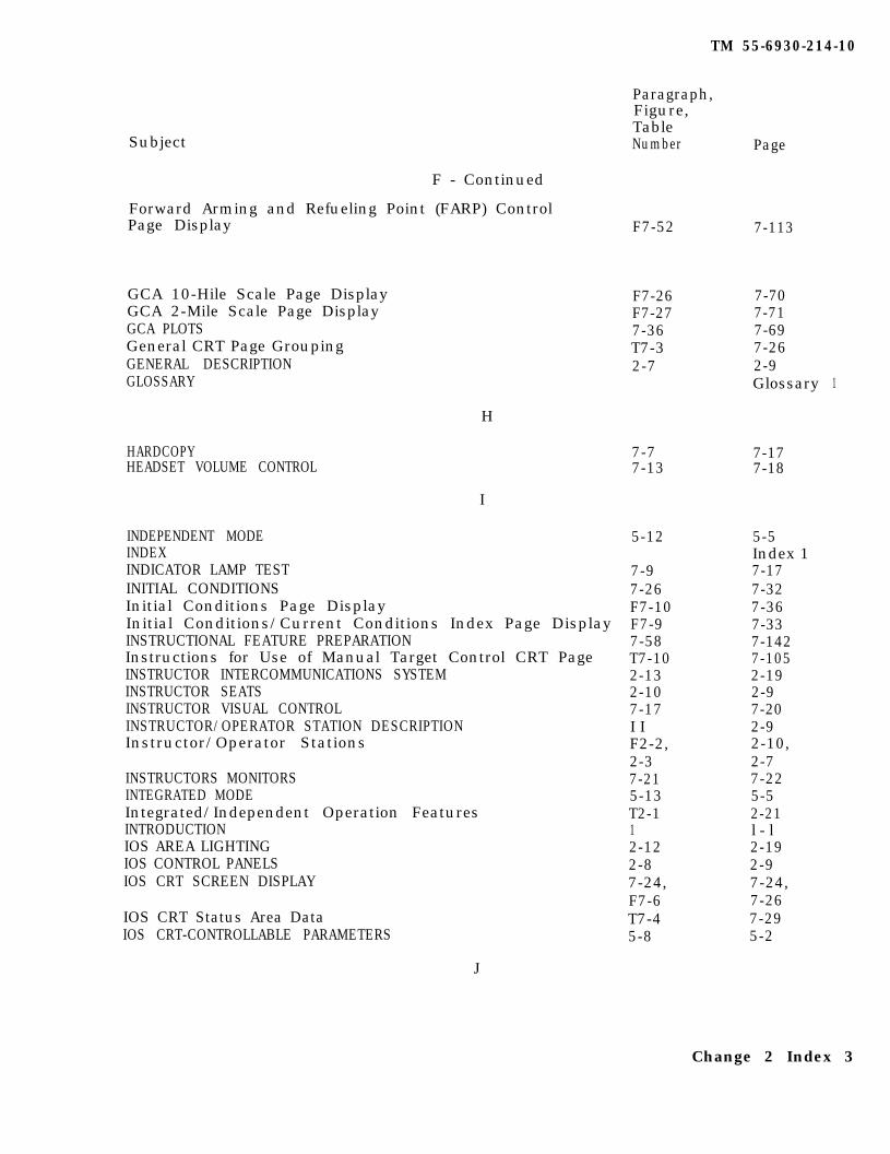
TM 55-6930-214-10
Paragraph,Figure,TableNumber PageSubject
F - Continued
Forward Arming and Refueling Point (FARP) ControlPage Display F7-52 7-113
GCA 10-Hile Scale Page DisplayGCA 2-Mile Scale Page DisplayGCA PLOTSGeneral CRT Page GroupingGENERAL DESCRIPTIONGLOSSARY
F7-26F7-277-36T7-32-7
7-707-717-697-262-9Glossary 1
H
HARDCOPY 7-7 7-17HEADSET VOLUME CONTROL 7-13 7-18
I
INDEPENDENT MODEINDEXINDICATOR LAMP TESTINITIAL CONDITIONSInitial Conditions Page DisplayInitial Conditions/Current Conditions Index Page DisplayINSTRUCTIONAL FEATURE PREPARATIONInstructions for Use of Manual Target Control CRT PageINSTRUCTOR INTERCOMMUNICATIONS SYSTEMINSTRUCTOR SEATSINSTRUCTOR VISUAL CONTROLINSTRUCTOR/OPERATOR STATION DESCRIPTIONInstructor/Operator Stations
5-12
INSTRUCTORS MONITORSINTEGRATED MODEIntegrated/Independent Operation FeaturesINTRODUCTIONIOS AREA LIGHTINGIOS CONTROL PANELSIOS CRT SCREEN DISPLAY
IOS CRT Status Area DataIOS CRT-CONTROLLABLE PARAMETERS
7-97-26F7-10F7-97-58T7-102-132-107-17I IF2-2,2-37-215-13T2-112-122-87-24,F7-6T7-45-8
5-5Index 17-177-327-367-337-1427-1052-192-97-202-92-10,2-77-225-52-21l - l2-192-97-24,7-267-295-2
J
Change 2 Index 3
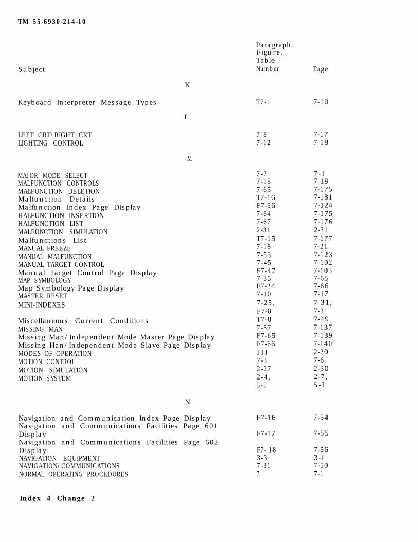
TM 55-6930-214-10
K
L
M
Paragraph,Figure,TableNumber PageSubject
Keyboard Interpreter Message Types T7-1 7-10
LEFT CRT/RIGHT CRT 7-8 7-17LIGHTING CONTROL 7-12 7-18
MAJOR MODE SELECTMALFUNCTION CONTROLSMALFUNCTION DELETIONMalfunction DetailsMalfunction Index Page DisplayHALFUNCTION INSERTIONHALFUNCTION LISTMALFUNCTION SIMULATIONMalfunctions ListMANUAL FREEZEMANUAL MALFUNCTIONMANUAL TARGET CONTROLManual Target Control Page DisplayMAP SYMBOLOGYMap Symbology Page DisplayMASTER RESETMINI-INDEXES
7-2 7-l7-15 7-197-65 7-175T7-16 7-181F7-56 7-1247-64 7-1757-67 7-1762-31 2-31T7-15 7-1777-18 7-217-53 7-1237-45 7-102F7-47 7-1037-35 7-65F7-24 7-667-10 7-177-25, 7-31,F7-8 7-31T7-8 7-497-57 7-137F7-65 7-139F7-66 7-140I I I 2-207-3 7-62-27 2-302-4, 2-7,5-5 5-l
Miscellaneous Current ConditionsMISSING MANMissing Man/Independent Mode Master Page DisplayMissing Han/Independent Mode Slave Page DisplayMODES OF OPERATIONMOTION CONTROLMOTION SIMULATIONMOTION SYSTEM
N
F7-16 7-54Navigation and Communication Index Page DisplayNavigation and Communications Facilities Page 601DisplayNavigation and Communications Facilities Page 602DisplayNAVIGATION EQUIPMENTNAVIGATION/COMMUNICATIONSNORMAL OPERATING PROCEDURES
F7-17 7-55
F7- 18 7-563-3 3-l7-31 7-507 7-1
Index 4 Change 2
TM 55-6930-214-10
Subject
O
OBSERVER COMMUNICATIONS PANEL
OBSERVER SEATSOCCUPANCYOPERATING LIMITS AND RESTRICTIONSOPERATIONAL SAFETYOPERATIONAL SYSTEMOwnship Engagement Performance Page Display
P
PARAMETER FREEZEParameter Freeze Page DisplayPilot Cyclic Page DisplayPilot Fire Control Panel Page DisplayPilot Missile Control Panel Page DisplayPilot/CPG IOS Console Control Panels
Pilot/CPG Trainee Control PanelPREFACE
Q
R
RADAR AND TRANSPONDER EQUIPMENTRADIO COMMUNICATION AND INTERCOMMUNICATION SYSTEM(ICS) SIMULATIONRange of Values for Current Conditions Line EntriesRange of Values for Initial Conditions Line EntriesRECORD/PLAYBACKRecord/Playback Command Page DisplayREMOTE DISPLAYREPLAY CONTROLREPORTING OF ERRORSRocket Configuration Page Display
S
SAFETYSAFETY SUMMARYSCOPESecurity RequirementsSIMULATED MALFUNCTIONSSIMULATION SYSTEM CAPABILITIES
Paragraph,Figure.TableNumber Page
7-23, 7-24,F7-5 7-252-11 2-95-4 5-l5 5-l8-4 8-32-l 2-lF7-53 7-114.1
7-28F7-13F7-36F7-33F7-32F2-3,F7-1,F2-4,F7-4F7-2
3-4
2-30 2-31T7-6 7-45T7-5 7-387-56 7-136F7-64 7-1387-8 7-177-20 7-22l-5 l - lF7-51 7-112
I I
l - l
I v2-21
7-497-517-817-787-772-11,7-2,2-15,7-167-7i
3-1
8-3x ll - li7-1752-24
Change 2 Index 5
TM 55-6930-214-10
Subject
!
SIMULATOR COMPARTMENTSSOUND SIMULATIONSTATUS INTERCHANGESTORE/RESET CURRENT CONDITIONSSYSTEM DESCRIPTION AND OPERATIONSYSTEM FAILURESSYSTEMS SIMULATED
S - Continued
T
Tactical Instrument Gaming Area (Zoom On) Page DisplayTACTICAL INSTRUMENT GAMING AREA DISPLAYTactical Instrument Gaming Area Page DisplayTACTICSTactics Current ConditionsTADS UNIT TARGETSTARGET ENGAGEMENT EXERCISETarget Engagement Exercise Page DisplayTarget Engagement Exercise Prep Page DisplayTARGET ENGAGEMENT EXERCISE PREPARATIONTARGET EVALUATIONTarget Evaluation Page DisplayTARGET SITES LISTTarget Sites List Page DisplayTARGET SITES OVERVIEWTarget Sites Overview (Zoom On) Page DisplayTarget Sites Overview Page DisplayTARGET STATUSTarget Status InformationTarget Status Page DisplayTARGET TYPES LISTTarget Types List Page DisplayTECHNICAL MANUAL CHANGESTEE Prep Data Entry ProcedureTEE Prep Data WorksheetTEMPERATURE AND HUMIDITYTHREAT SCORINGThreat Scoring Page Data DisplayThreat Scoring Page DisplayTIME REFERENCESTRAINEE CONTROL PANELS
Trainee StationTRAINING
TRAINING CAPABILITIES
Paragraph,Figure,TableNumber
2-2 2-l2-26 2-307-8A 7-177-14 7-182 2-l8-2 8-1V 2-30
F7-23 7-647-34 7-62F7-22 7-634 4-lT7-7 7-485-11 5-47-39 7-83F7-38 7-84F7-71 7-1627-62 7-1617-47 7-108F7-49 7-1097-42 7-91F7-42 7-927-43 7-91F7-44 7-97F7-43 7-967-40 7-85T7-9 7-86F7-39 7-877-41 7-86F7-40 7-88l-3 l - lT7-14 7-170F7-72 7-1645-3 5-l7-51 7-114T7-12 7-118F7-54 7-1162-14 2-197-22, 7-24,F2-7, 2-18,2-9 2-9F2-6 2-172-16, 2-20,4-3 4-lI v 2-23
Page
Index 6 Change 2
TM 55-6930-214-10
Subject
T - Continued
TRAINING OBJECTIVESTRAINING TASKSTypical AH-64 CMS andComputer Rooms System ComplexTypical CRT Page Status AreasTypical Malfunctions Page DisplayTypical Map SymbolsTypical Target Symbols
U
V
VIBRATION SIMULATIONVISIONICS POINTING/REMOTE DESIGNATORVisionics Pointing/Remote Designator Control PageDisplayVisual Display AvailabilityVisual Gaming Weapons SymbolsVISUAL MODE HELP PAGEVisual Mode Help Page DisplayVisual Monitor Display ModesVISUAL SIMULATIONVISUAL SYSTEM
VISUAL SYSTEM CAPABILITIES
W
Weapons Loading Page Display F7-50 7-111WEAPONS LOADING/ROCKET CONFIGURATION 7-48 7-110
X
Y
Z
* U.S. GOVERNMENT PRINTING OFFICE: 1992 554-123/40048
Paragraph,Figure,TableNumber Page
2-20 2-232-23 2-26F2-1 2-2F7-7 7-29F7-57 7-126F7-25 7-67F7-45 7-98
2-28 2-307-46 7-102
F7-48 7-104T5-1 5-3F7-41 7-897-30 7-50F7-15 7-53T7-2 7-234-2 4-l2-5, 2-8,5-6, 5-2,6 6-l2-22 2-26
Change 2 Index 7/(Index 8 blank)

P I N : 063796-002

TM 55-6930-214-10
By Order of the Secretary of the Army:
Official:
CARL E. VUONOGeneral, United States Army
Chief of Staff
R. L. DILWORTHBrigadier General, United States Army
The Adjutant General
DISTRIBUTION:To be distributed in accordance with DA Form 12-31, -10 & CL maintenance require-
ments for AH-64A Helicopter, Attack (APACHE)


PIN 063796-000

This fine document...
Was brought to you by me:
Liberated Manuals -- free army and government manuals
Why do I do it? I am tired of sleazy CD-ROM sellers, who take publicly available information, slap “watermarks” and other junk on it, and sell it. Those masters of search engine manipulation make sure that their sites that sell free information, come up first in search engines. They did not create it... They did not even scan it... Why should they get your money? Why are not letting you give those free manuals to your friends?
I am setting this document FREE. This document was made by the US Government and is NOT protected by Copyright. Feel free to share, republish, sell and so on.
I am not asking you for donations, fees or handouts. If you can, please provide a link to liberatedmanuals.com, so that free manuals come up first in search engines:
<A HREF=http://www.liberatedmanuals.com/>Free Military and Government Manuals</A>
– SincerelyIgor Chudovhttp://igor.chudov.com/
– Chicago Machinery Movers