operator’s manual - kepcopower.com · p/n 243-1339-r13 important notes: 1) ... operator safety...
TRANSCRIPT

KEPCO® THE POWER SUPPLIER™
MODEL
OPERATOR’S MANUAL
ORDER NO.
KEPCO, INC. 131-38 SANFORD AVENUE FLUSHING, NY. 11355 U.S.A. TEL (718) 461-7000 FAX (718) 767-1102email: [email protected] World Wide Web: http://www.kepcopower.com
KEPCO INC.An ISO 9001 Company.
KLN 750W, 1500W, 3000W
PROGRAMMABLE D-C POWER SUPPLY
LOW PROFILE
KLN 750W, 1500W, 3000WPOWER SUPPLY
©2017, KEPCO, INCP/N 243-1339-r13
IMPORTANT NOTES:
1) This manual is valid for the following Firmware Versions:
FIRMWARE VERSION NOTE.
2) A Change Page may be included at the end of the manual. All applicable changes andrevision number changes are documented with reference to the equipment serial num-bers. Before using this Instruction Manual, check your equipment firmware version num-ber to identify your model. If in doubt, contact your nearest Kepco Representative, or theKepco Documentation Office in New York, (718) 461-7000, requesting the correct revisionfor your particular model and firmware version number.
3) The contents of this manual are protected by copyright. Reproduction of any part can bemade only with the specific written permission of Kepco, Inc.
Data subject to change without notice.
Main Control 1.70 and higher


KLN Series/ 022417 A
OPERATORSAFETY INSTRUCTIONS
Read these safety instructions, as well as the applicable installation and operating instructions contained in this manual before using the power supply.
Do not touch the output terminals. The output is dangerous. Electric shock can cause injury or death.
Do not remove the cover or disassemble the unit. There are no operator serviceable components or adjustments inside the unit. High voltage components inside the unit can cause serious injury even with input power disconnected.
Service must be referred to authorized personnel. Using the power supply in a manner not specified by Kepco. Inc. may impair the protection provided by the power supply. Observe all safety precautions noted throughout this manual. Table 1-6 lists symbols used on the power supply or in this manual where applica-ble.
WARNING


KLN Series 022417 i
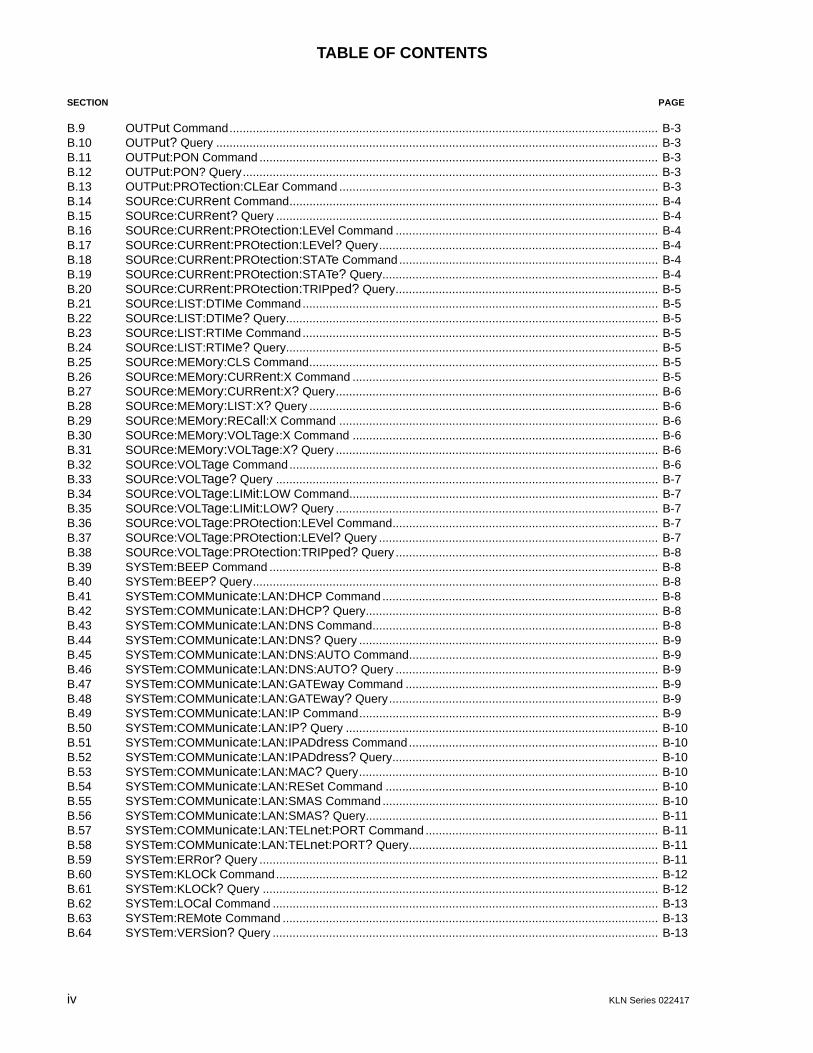
TABLE OF CONTENTS
SECTION PAGE
SECTION 1 - INTRODUCTION1.1 Scope of Manual ..................................................................................................................................... 1-11.2 General Description................................................................................................................................. 1-11.3 Specifications .......................................................................................................................................... 1-21.4 Local Control ........................................................................................................................................... 1-121.5 Remote Control ....................................................................................................................................... 1-121.6 Analog Control......................................................................................................................................... 1-121.7 Features .................................................................................................................................................. 1-121.7.1 Digital Calibration............................................................................................................................... 1-121.7.2 Protection........................................................................................................................................... 1-121.7.3 Saving and Recalling Settings........................................................................................................... 1-121.7.4 Parallel and Series Configurations .................................................................................................... 1-121.7.5 Miscellaneous Features..................................................................................................................... 1-131.8 Equipment Supplied ................................................................................................................................ 1-131.9 Accessories ............................................................................................................................................. 1-141.10 Safety ...................................................................................................................................................... 1-15
SECTION 2 - INSTALLATION2.1 Unpacking and Inspection ....................................................................................................................... 2-12.2 Terminations and Controls ...................................................................................................................... 2-12.3 Preliminary Operational Check................................................................................................................ 2-42.4 Installation ............................................................................................................................................... 2-62.4.1 Rack Mounting 750W Models............................................................................................................ 2-62.4.1.1 Mounting One 750W 1/2-rack Unit in 19-inch Rack..................................................................... 2-62.4.1.2 Mounting Two 750W 1/2-rack Units in 19-inch Rack ................................................................... 2-62.4.2 Rack Mounting 1500W Models.......................................................................................................... 2-72.4.3 Rack Mounting 3000W Models.......................................................................................................... 2-72.5 Wiring Instructions................................................................................................................................... 2-72.5.1 Safety Grounding............................................................................................................................... 2-72.5.2 Source Power Connections ............................................................................................................... 2-82.5.3 D-C Output Grounding....................................................................................................................... 2-82.5.4 Power Supply/Load Interface............................................................................................................. 2-92.5.5 Load Connection - General................................................................................................................ 2-92.5.6 Load Connection Using Local Sensing.............................................................................................. 2-112.5.7 Load Connection Using Remote Sensing.......................................................................................... 2-122.6 Cooling .................................................................................................................................................... 2-132.7 Setting up the unit ................................................................................................................................... 2-132.7.1 Setup for Local Operation.................................................................................................................. 2-132.7.2 Setup for Remote Operation via RS-485........................................................................................... 2-132.7.3 Setup for Remote Operation via USB)............................................................................................... 2-142.7.4 Setup for Remote Operation via GPIB (IEEE 488) ............................................................................ 2-142.7.5 Setup for Remote Operation via LAN ................................................................................................ 2-152.8 Multiple Unit Configurations .................................................................................................................... 2-162.8.1 Series Connections............................................................................................................................ 2-162.8.2 Parallel Connections.......................................................................................................................... 2-18
SECTION 3 - OPERATION3.1 General.................................................................................................................................................... 3-13.2 Power Supply Basics............................................................................................................................... 3-23.2.1 Turning the Power Supply On............................................................................................................ 3-43.2.2 Menu Structure .................................................................................................................................. 3-63.3 Local Mode Operation ............................................................................................................................. 3-63.3.1 Setting Local/Remote Mode .............................................................................................................. 3-63.3.1.1 Front Panel Lockout..................................................................................................................... 3-83.3.2 Set Voltage or Overvoltage Protection (OVP) ................................................................................... 3-83.3.3 Set Current or Overcurrent Protection (OCP).................................................................................... 3-8

ii KLN Series 022417
TABLE OF CONTENTS
SECTION PAGE
3.3.4 OVP/OVC Operation and Recovery.................................................................................................. 3-93.3.5 Enabling/Disabling DC Output Power ............................................................................................... 3-93.3.6 Storing Power Supply Output Settings.............................................................................................. 3-93.3.7 Recalling Power Supply Output Settings .......................................................................................... 3-103.3.8 Output Mode (Voltage Set: Direct or Enter) ...................................................................................... 3-103.3.9 Power On Setting.............................................................................................................................. 3-113.3.10 Rise Time (Ramp up)........................................................................................................................ 3-113.3.11 Fall Time (Ramp Down) .................................................................................................................... 3-113.3.12 Memory Flag ..................................................................................................................................... 3-123.3.13 Beep.................................................................................................................................................. 3-123.3.14 Display Brightness ............................................................................................................................ 3-123.3.15 I/O Select .......................................................................................................................................... 3-133.3.16 RS-485 Baud Rate............................................................................................................................ 3-133.3.17 GPIB Address (GPIB Interface Only)................................................................................................ 3-133.3.18 RS-485 Address................................................................................................................................ 3-143.3.19 DHCP Function On/Off Control (LAN Interface Only) ....................................................................... 3-143.3.20 DNS Function On/Off Control (LAN Interface Only).......................................................................... 3-163.3.21 Set/View 1st Part of IP Address (LAN Interface Only) ...................................................................... 3-163.3.22 Set/View 2nd Part of IP Address (LAN Interface Only)..................................................................... 3-173.3.23 Set/View 3rd Part of IP Address (LAN Interface Only)...................................................................... 3-173.3.24 Set/View 4th Part of IP Address (LAN Interface Only)...................................................................... 3-183.3.25 Set/View 1st Part of Subnet Mask Address (LAN Interface Only) .................................................... 3-183.3.26 Set/View 2nd Part of Subnet Mask Address (LAN Interface Only) ................................................... 3-193.3.27 Set/View 3rd Part of Subnet Mask Address (LAN Interface Only) .................................................... 3-193.3.28 Set/View 4th Part of Subnet Mask Address (LAN Interface Only) .................................................... 3-193.3.29 Set/View 1st Part of Gateway Address (LAN Interface Only) ........................................................... 3-203.3.30 Set/View 2nd Part of Gateway Address (LAN Interface Only) .......................................................... 3-203.3.31 Set/View 3rd Part of Gateway Address (LAN Interface Only)........................................................... 3-203.3.32 Set/View 4th Part of Gateway Address (LAN Interface Only) ........................................................... 3-213.3.33 Set/View 1st Part of DNS Address (LAN Interface Only).................................................................. 3-213.3.34 Set/View 2nd Part of DNS Address (LAN Interface Only)................................................................. 3-213.3.35 Set/View 3rd Part of DNS Address (LAN Interface Only) ................................................................. 3-223.3.36 Set/View 4th Part of DNS Address (LAN Interface Only).................................................................. 3-223.3.37 Parallel/Serial Master/Slave Setup ................................................................................................... 3-223.3.38 External Control of Output On/Off..................................................................................................... 3-233.3.39 Enable Voltage Control via Programming Control Port..................................................................... 3-233.3.40 Enable Current Control via Programming Control Port..................................................................... 3-233.3.41 Calibration Access ............................................................................................................................ 3-243.3.42 View Serial Number .......................................................................................................................... 3-243.3.43 View Main Control Version................................................................................................................ 3-243.3.44 View Hardware Version .................................................................................................................... 3-243.3.45 View 1st Part of MAC Address (LAN Interface Only)........................................................................ 3-243.3.46 View 2nd Part of MAC Address (LAN Interface Only)....................................................................... 3-253.3.47 View 3rd Part of MAC Address (LAN Interface Only) ....................................................................... 3-253.3.48 Reset................................................................................................................................................. 3-253.3.49 IP Address Reset (RST1) ................................................................................................................. 3-263.3.50 Viewing Error Codes. ........................................................................................................................ 3-263.4 Series/Parallel Operation........................................................................................................................ 3-263.4.1 Series Operation ............................................................................................................................... 3-263.4.2 Discontinuing Series Operation ........................................................................................................ 3-273.4.3 Parallel Operation ............................................................................................................................. 3-283.4.4 Discontinuing Parallel Operation....................................................................................................... 3-293.5 Analog Remote Mode Programming ...................................................................................................... 3-293.5.1 Remote Output On/off....................................................................................................................... 3-293.5.2 Remote Emergency Shutdown ......................................................................................................... 3-29

KLN Series 022417 iii
TABLE OF CONTENTS
SECTION PAGE
3.5.3 Remote Control of Output Voltage Using an analog signal ............................................................... 3-303.5.4 Remote Control of Output Current Using an analog signal ............................................................... 3-303.5.5 Recalling Previously Stored Setting Using Programming Control Port.............................................. 3-303.5.6 Monitoring Output Status Using Programming Control Port .............................................................. 3-303.5.6.1 Monitor Output Voltage or Current............................................................................................... 3-303.5.6.2 Monitor Unit Status ...................................................................................................................... 3-313.6 Digital Remote Mode Programming ........................................................................................................ 3-313.6.1 RS-485 Operation.............................................................................................................................. 3-313.6.2 GPIB Operation (If Option Installed) .................................................................................................. 3-313.6.2.1 IEEE 488 (GPIB) Bus Protocol .................................................................................................... 3-323.6.3 LAN Operation (If Option Installed).................................................................................................... 3-343.6.3.1 Network Status............................................................................................................................. 3-353.6.3.2 Viewing and/or Changing IP Configuration .................................................................................. 3-353.6.3.3 Changing LAN Password............................................................................................................. 3-373.6.3.4 Instrument Control ....................................................................................................................... 3-373.6.3.5 Operation Via HyperTerminal. ..................................................................................................... 3-383.7 SCPI Programming ................................................................................................................................. 3-393.7.1 SCPI Messages................................................................................................................................. 3-403.7.2 Common Commands/Queries ........................................................................................................... 3-403.7.3 SCPI Subsystem Command/query Structure .................................................................................... 3-403.7.3.1 Calibrate Subsystem.................................................................................................................... 3-403.7.3.2 Display Subsystem ...................................................................................................................... 3-403.7.3.3 Fetch Subsystem ......................................................................................................................... 3-403.7.3.4 Output Subsystem ....................................................................................................................... 3-403.7.3.5 Source Subsystem....................................................................................................................... 3-403.7.3.6 System Subsystem ...................................................................................................................... 3-403.7.4 Understanding The Command Structure ........................................................................................... 3-41
SECTION 4 - CALIBRATION4.1 General.................................................................................................................................................... 4-14.2 Equipment Required................................................................................................................................ 4-14.3 Voltage Calibration Procedure ................................................................................................................ 4-14.4 Current Calibration Procedure................................................................................................................. 4-3
APPENDIX A - SCPI COMMON COMMAND/QUERY DEFINITIONS
A.2 *CLS — Clear Status Command ............................................................................................................ A-1A.3 *IDN? — Identification Query ................................................................................................................. A-1A.4 *RST — Reset Command ...................................................................................................................... A-1A.5 *TST? — Self Test Query....................................................................................................................... A-1
APPENDIX B - SCPI COMMAND/QUERY DEFINITIONS
B.1 Introduction............................................................................................................................................. B-1B.2 Numerical Values ................................................................................................................................... B-1B.3 DISP:CONTrast Command.................................................................................................................... B-1B.4 DISP:CONTrast? Query ........................................................................................................................ B-2B.5 FETCh? Query ....................................................................................................................................... B-2B.6 MEASure:ADDRess? Query ................................................................................................................. B-2B.7 MEASure:CURRent? Query.................................................................................................................. B-2B.8 MEASure:VOLTage? Query.................................................................................................................. B-2
iv KLN Series 022417
TABLE OF CONTENTS
SECTION PAGE
B.9 OUTPut Command................................................................................................................................. B-3B.10 OUTPut? Query ..................................................................................................................................... B-3B.11 OUTPut:PON Command ........................................................................................................................ B-3B.12 OUTPut:PON? Query............................................................................................................................. B-3B.13 OUTPut:PROTection:CLEar Command ................................................................................................ B-3B.14 SOURce:CURRent Command............................................................................................................... B-4B.15 SOURce:CURRent? Query ................................................................................................................... B-4B.16 SOURce:CURRent:PROtection:LEVel Command ............................................................................... B-4B.17 SOURce:CURRent:PROtection:LEVel? Query.................................................................................... B-4B.18 SOURce:CURRent:PROtection:STATe Command.............................................................................. B-4B.19 SOURce:CURRent:PROtection:STATe? Query................................................................................... B-4B.20 SOURce:CURRent:PROtection:TRIPped? Query............................................................................... B-5B.21 SOURce:LIST:DTIMe Command........................................................................................................... B-5B.22 SOURce:LIST:DTIMe? Query................................................................................................................ B-5B.23 SOURce:LIST:RTIMe Command........................................................................................................... B-5B.24 SOURce:LIST:RTIMe? Query................................................................................................................ B-5B.25 SOURce:MEMory:CLS Command......................................................................................................... B-5B.26 SOURce:MEMory:CURRent:X Command ............................................................................................ B-5B.27 SOURce:MEMory:CURRent:X? Query................................................................................................. B-6B.28 SOURce:MEMory:LIST:X? Query ......................................................................................................... B-6B.29 SOURce:MEMory:RECall:X Command ................................................................................................ B-6B.30 SOURce:MEMory:VOLTage:X Command ............................................................................................ B-6B.31 SOURce:MEMory:VOLTage:X? Query ................................................................................................. B-6B.32 SOURce:VOLTage Command............................................................................................................... B-6B.33 SOURce:VOLTage? Query ................................................................................................................... B-7B.34 SOURce:VOLTage:LIMit:LOW Command............................................................................................. B-7B.35 SOURce:VOLTage:LIMit:LOW? Query ................................................................................................. B-7B.36 SOURce:VOLTage:PROtection:LEVel Command................................................................................ B-7B.37 SOURce:VOLTage:PROtection:LEVel? Query .................................................................................... B-7B.38 SOURce:VOLTage:PROtection:TRIPped? Query ............................................................................... B-8B.39 SYSTem:BEEP Command ..................................................................................................................... B-8B.40 SYSTem:BEEP? Query.......................................................................................................................... B-8B.41 SYSTem:COMMunicate:LAN:DHCP Command ................................................................................... B-8B.42 SYSTem:COMMunicate:LAN:DHCP? Query........................................................................................ B-8B.43 SYSTem:COMMunicate:LAN:DNS Command...................................................................................... B-8B.44 SYSTem:COMMunicate:LAN:DNS? Query .......................................................................................... B-9B.45 SYSTem:COMMunicate:LAN:DNS:AUTO Command........................................................................... B-9B.46 SYSTem:COMMunicate:LAN:DNS:AUTO? Query ............................................................................... B-9B.47 SYSTem:COMMunicate:LAN:GATEway Command ............................................................................ B-9B.48 SYSTem:COMMunicate:LAN:GATEway? Query................................................................................. B-9B.49 SYSTem:COMMunicate:LAN:IP Command.......................................................................................... B-9B.50 SYSTem:COMMunicate:LAN:IP? Query .............................................................................................. B-10B.51 SYSTem:COMMunicate:LAN:IPADdress Command........................................................................... B-10B.52 SYSTem:COMMunicate:LAN:IPADdress? Query................................................................................ B-10B.53 SYSTem:COMMunicate:LAN:MAC? Query.......................................................................................... B-10B.54 SYSTem:COMMunicate:LAN:RESet Command .................................................................................. B-10B.55 SYSTem:COMMunicate:LAN:SMAS Command ................................................................................... B-10B.56 SYSTem:COMMunicate:LAN:SMAS? Query........................................................................................ B-11B.57 SYSTem:COMMunicate:LAN:TELnet:PORT Command ...................................................................... B-11B.58 SYSTem:COMMunicate:LAN:TELnet:PORT? Query........................................................................... B-11B.59 SYSTem:ERRor? Query ........................................................................................................................ B-11B.60 SYSTem:KLOCk Command................................................................................................................... B-12B.61 SYSTem:KLOCk? Query ....................................................................................................................... B-12B.62 SYSTem:LOCal Command .................................................................................................................... B-13B.63 SYSTem:REMote Command ................................................................................................................. B-13B.64 SYSTem:VERSion? Query .................................................................................................................... B-13
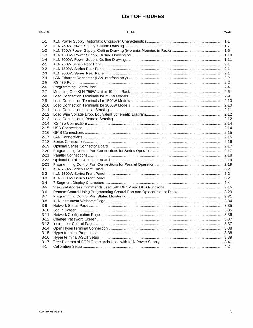
LIST OF FIGURES
FIGURE TITLE PAGE
KLN Series 022417 v
1-1 KLN Power Supply, Automatic Crossover Characteristics.......................................................................... 1-11-2 KLN 750W Power Supply, Outline Drawing................................................................................................ 1-71-2 KLN 750W Power Supply, Outline Drawing (two units Mounted in Rack) .................................................. 1-81-3 KLN 1500W Power Supply, Outline Drawing sd ......................................................................................... 1-101-4 KLN 3000W Power Supply, Outline Drawing.............................................................................................. 1-112-1 KLN 750W Series Rear Panel .................................................................................................................... 2-12-2 KLN 1500W Series Rear Panel .................................................................................................................. 2-12-3 KLN 3000W Series Rear Panel .................................................................................................................. 2-12-4 LAN Ethernet Connector (LAN Interface only) ............................................................................................ 2-22-5 RS-485 Port ................................................................................................................................................ 2-22-6 Programming Control Port .......................................................................................................................... 2-42-7 Mounting One KLN 750W Unit in 19-inch Rack.......................................................................................... 2-62-8 Load Connection Terminals for 750W Models ............................................................................................ 2-92-9 Load Connection Terminals for 1500W Models .......................................................................................... 2-102-10 Load Connection Terminals for 3000W Models .......................................................................................... 2-102-11 Load Connections, Local Sensing .............................................................................................................. 2-112-12 Load Wire Voltage Drop, Equivalent Schematic Diagram........................................................................... 2-122-13 Load Connections, Remote Sensing .......................................................................................................... 2-122-14 RS-485 Connections................................................................................................................................... 2-142-15 USB Connections........................................................................................................................................ 2-142-16 GPIB Connections ...................................................................................................................................... 2-152-17 LAN Connections ........................................................................................................................................ 2-152-18 Series Connections..................................................................................................................................... 2-162-19 Optional Series Connector Board ............................................................................................................... 2-172-20 Programming Control Port Connections for Series Operation .................................................................... 2-172-21 Parallel Connections ................................................................................................................................... 2-182-22 Optional Parallel Connector Board ............................................................................................................. 2-192-23 Programming Control Port Connections for Parallel Operation .................................................................. 2-193-1 KLN 750W Series Front Panel .................................................................................................................... 3-23-2 KLN 1500W Series Front Panel .................................................................................................................. 3-23-3 KLN 3000W Series Front Panel .................................................................................................................. 3-23-4 7-Segment Display Characters ................................................................................................................... 3-43-5 View/Set Address Commands used with DHCP and DNS Functions......................................................... 3-153-6 Remote Control Using Programming Control Port and Optocoupler or Relay............................................ 3-293-7 Programming Control Port Status Monitoring ............................................................................................. 3-313-8 KLN Instrument Welcome Page.................................................................................................................. 3-343-9 Network Status Page .................................................................................................................................. 3-353-10 Log In Screen.............................................................................................................................................. 3-353-11 Network Configuration Page ....................................................................................................................... 3-363-12 Change Password Screen .......................................................................................................................... 3-373-13 Instrument Control Page ............................................................................................................................. 3-373-14 Open HyperTerminal Connection ............................................................................................................... 3-383-15 Hyper terminal Properties ........................................................................................................................... 3-383-16 Hyper terminal ASCII Setup........................................................................................................................ 3-393-17 Tree Diagram of SCPI Commands Used with KLN Power Supply ............................................................. 3-414-1 Calibration Setup ........................................................................................................................................ 4-2

vi KLN Series SVC 022417
LIST OF TABLES
TABLE TITLE PAGE
1-1 KLN Series Model Parameters ................................................................................................................... 1-21-2 KLN General Specifications ....................................................................................................................... 1-31-3 Equipment Supplied ................................................................................................................................... 1-131-4 Accessories ................................................................................................................................................ 1-141-5 Safety Symbols .......................................................................................................................................... 1-152-1 Rear Panel Connector Functions ............................................................................................................... 2-22-2 RS-485 Port Input/Output Pin Assignments ............................................................................................... 2-22-3 GPIB (IEEE 488) Port Input/Output Pin Assignments ................................................................................ 2-32-4 Programming Control Port I/O Pin Assignments ........................................................................................ 2-32-5 Maximum Load Wire Length for Voltage drop less than 1V ....................................................................... 2-123-1 Front Panel Controls and Indicators ........................................................................................................... 3-33-2 Factory Defaults ......................................................................................................................................... 3-53-3 Menu Functions .......................................................................................................................................... 3-73-4 IEEE 488 (GPIB) Bus Interface Functions ................................................................................................. 3-323-5 IEEE 488 (GPIB) Bus Command Mode Messages .................................................................................... 3-333-6 IEEE 488 (GPIB) Bus Data Mode Messages ............................................................................................. 3-333-7 VISA Resource String Corresponding to Interface ..................................................................................... 3-39A-1 IEEE 488.2 Command/query Index ............................................................................................................A-1B-1 SCPI Subsystem Command/query Index ...................................................................................................B-1B-2 Error Codes ................................................................................................................................................B-11

KLN Series 022417 1-1
SECTION 1 - INTRODUCTION
1.1 SCOPE OF MANUAL
This manual contains instructions for the installation and operation of the KLN series of 750,1500W, and 3000W Watt programmable, voltage and current stabilized d-c power supplies,hereafter referred to as KLN, from Kepco, Inc., Flushing, New York, U.S.A.
1.2 GENERAL DESCRIPTION
KLN Series power supplies are voltage and current stabilized d-c sources with a sharp cross-over between the constant voltage and constant current mode of operation. Thirty-nine modelsare offered, 13 in each power grouping, with rated d-c output voltage ranging from 6V to 600Vand rated d-c output current ranging from 1.25A to 400A (see Table 1-1).
KLN switching power supplies operate from wide range 100-240V a-c (190-240V a-c for3000W), 50/60 Hz input source power and employ active power factor correction (PFC). Sincethere are no internal adjustments, KLN Power Supplies offer excellent output voltage/currentstability and easy calibration.
Output voltage and current are displayed on independent LED displays. Control of the KLN canbe either local, via the front panel controls and displays, or remote, using 1) either analog sig-nals (applied to the Programming Control Port), or 2) digital programming. Digital programmingof standard models is via RS-485 communication bus. Optional IEEE 488.2 (GPIB) and LANinterfaces are also available.
KLN output and readback are high resolution: 16 bits D/A to set output voltage and current, 24bits A/D for readback of output voltage and current. These units feature a low temperature coef-ficient: Constant Voltage mode: 100ppm/°C, Constant Current mode: 100ppm/°C, and built-inremote sensing with a maximum compensation of 5V voltage drop across power lines.
The KLN series is suitable for ATE automatic test, burn- in test and other applications thatrequire lots of testing power.
The KLN power supply acts as a constant voltage source for comparatively large values of loadresistance, and as a constant current source for comparatively small values of load resistance.The transition between these two modes of operation occurs automatically at a “critical” or“crossover” value of load resistance Rc = Es/Is, where Es is the voltage control setting and Isis the current control setting (see Figure 1-1).
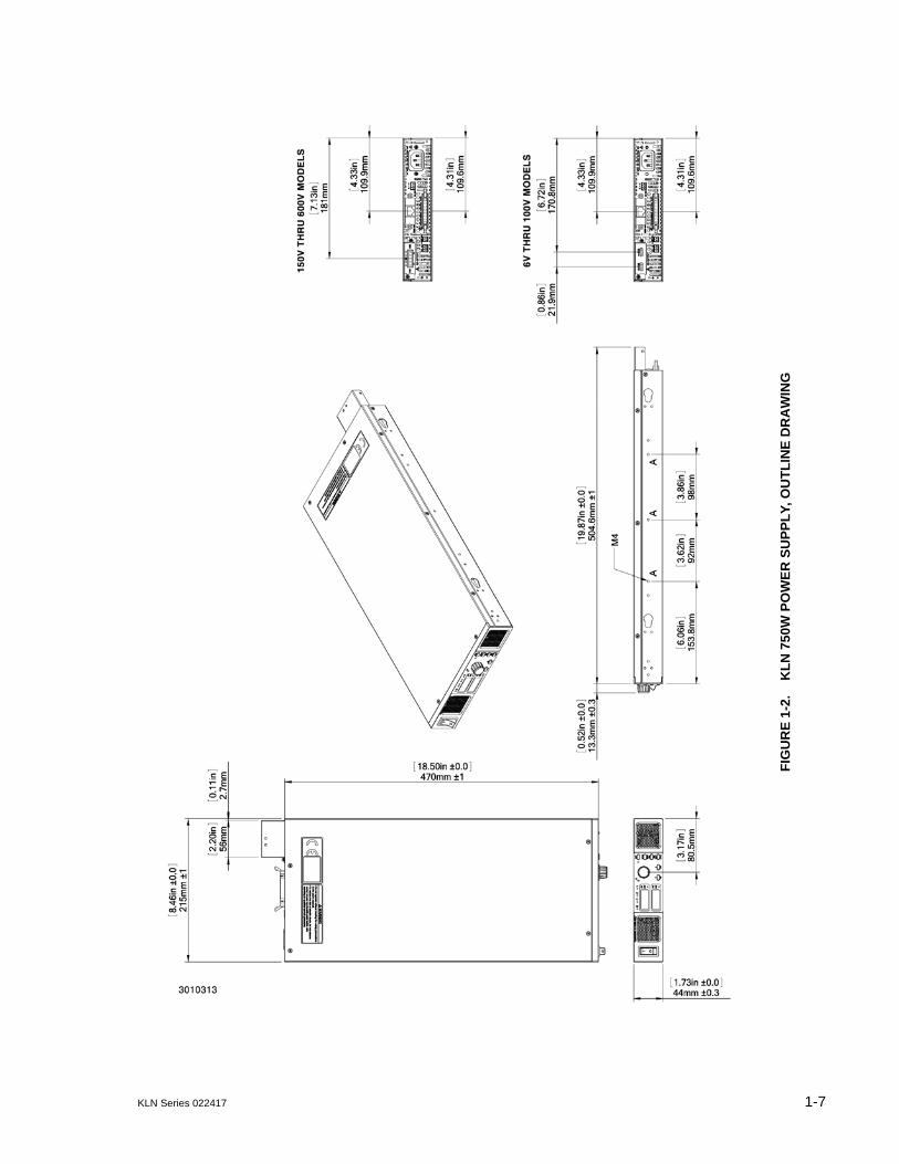
FIGURE 1-1. KLN POWER SUPPLY, AUTOMATIC CROSSOVER CHARACTERISTICS

1-2 KLN Series 022417
1.3 SPECIFICATIONS
Table 1-1 below indicates parameters that vary for different KLN models; Table 1-2 lists generalspecifications that apply to all KLN models.
TABLE 1-1. KLN SERIES MODEL PARAMETERS
Model(8)(9)(11)(12)
d-c Output Range Ripple(3) Line Regulation(5)(10) Load Regulation(10) Response Time(7) Remote SenseVoltage
drop (max.)
Constant Voltage
(CV)(1)
Constant Current
(CC)(2)CV CC(4) CV CC CV(6) CC(6)
Full Load Up
Full Load Down
No Load Down
V d-c A d-cmV rms
mA rms
0.05%+mV
0.1%+mA
0.05%+mV
0.1%+mA
Sec Sec Sec V
750W 1U Half Rack Models
KLN 6-100 0 to 6 0 to 100 10 180 2.8 11 2.8 23 0.08 0.05 0.6 1
KLN 8-90 0 to 8 0 to 90 10 180 2.8 11 2.8 23 0.08 0.05 0.6 1
KLN 12.5-60 0 to 12.5 0 to 60 10 120 4 8.5 4 18 0.08 0.05 0.8 1
KLN 20-38 0 to 20 0 to 38 10 76 4 5.8 4 12.6 0.08 0.05 0.8 1
KLN 30-25 0 to 30 0 to 25 10 63 5 4.5 5 10 0.08 0.08 0.9 1.5
KLN 40-19 0 to 40 0 to 19 10 48 6 3.9 6 8.8 0.08 0.08 1 2
KLN 50-15 0 to 50 0 to 15 10 43 8 3.6 8 8.2 0.08 0.08 1.1 2
KLN 60-12.5 0 to 60 0 to 12.5 10 38 8 3.25 8 7.5 0.08 0.08 1.1 3
KLN 80-9.5 0 to 80 0 to 9.5 10 29 10 2.95 10 6.9 0.15 0.15 1.2 4
KLN 100-7.5 0 to 100 0 to 7.5 10 23 12 2.75 12 6.5 0.15 0.15 1.5 5
KLN 150-5 0 to 150 0 to 5 16 18 17 2.5 17 6 0.15 0.15 2 5
KLN 300-2.5 0 to 300 0 to 2.5 25 13 32 2.25 32 5.5 0.15 0.15 3 5
KLN 600-1.25 0 to 600 0 to 1.25 75 8 62 2.13 62 5.26 0.25 0.3 4 5
1500W 1U Full Rack Models
KLN 6-200 0 to 6 0 to 200 15 360 2.8 18.5 2.8 38 0.08 0.05 0.6 1
KLN 8-180 0 to 8 0 to 180 15 360 2.8 18.5 2.8 38 0.08 0.05 0.6 1
KLN 12.5-120 0 to 12.5 0 to 120 15 248 3.4 14.5 4 28 0.08 0.05 0.8 1
KLN 20-76 0 to 20 0 to 76 15 152 4 9.6 4 20.2 0.08 0.05 0.8 1
KLN 30-50 0 to 30 0 to 50 15 125 5 7 5 15 0.08 0.08 0.9 1.5
KLN 40-38 0 to 40 0 to 38 15 95 6 5.8 6 12.6 0.08 0.08 1 2
KLN 50-30 0 to 50 0 to 30 15 85 7 5.2 7 11.4 0.08 0.08 1.1 2
KLN 60-25 0 to 60 0 to 25 15 75 8 4.5 8 10 0.08 0.08 1.1 3
KLN 80-19 0 to 80 0 to 19 15 57 10 3.9 10 8.8 0.15 0.15 1.2 4
KLN 100-15 0 to 100 0 to 15 15 45 12 3.5 12 8 0.15 0.15 1.5 5
KLN 150-10 0 to 150 0 to 10 24 45 12 3.5 12 8 0.15 0.15 2 5
KLN 300-5 0 to 300 0 to 5 38 25 32 2.5 32 6 0.15 0.15 3 5
KLN 600-2.5 0 to 600 0 to 2.5 113 15 62 2.26 62 5.5 0.25 0.3 4 5
NOTES: 1. Actual output voltage should be 0.1% of rated voltage when output voltage is set to zero.2. Actual output current should be 0.2% of the rated current when output current is set to zero (resistive load).3. Measured when output is within 10%-100% of rated value; ripple bandwidth: 300kHz (rms), noise bandwidth: <20MHz (p-p).4. For 6V model: measured when output voltage 2-6V and rated current; all other models measured when output 10-100% of rated voltage and rated
current.5. Input voltage 100-240V a-c (190-240V a-c for 3000W models), 50/60Hz, constant load.6. Constant input voltage and output from no load to full load.7. With rated input, resistive load.8. Rated power output with input 115V or 230V a-c9. Specifications met after 30 minutes of operation, ambient temperature 23±5°C, humidity under 80% R. H, nominal a-c input voltage ±5%, THD 2%,
not using the remote compensation, not operating in series or parallel.10. For example, the spec for KLN 6-100 line regulation and load regulation in CV mode is 0.05% + 2.8mV (or 6 x 0.0005 = 3mV +2.8mV =5.8mV).11. Add G suffix for models with optional GPIB interface, add E suffix for optional LAN interface.12. Specifications subject to change without notice.

KLN Series 022417 1-3
3000W 2U Full Rack Models
KLN 6-400 0 to 6 0 to 400 23 1000 2.8 42 6.2 85 0.08 0.02 0.5 1
KLN 8-360 0 to 8 0 to 360 23 1000 2.8 42 6.2 85 0.08 0.02 0.5 1
KLN 12.5-240 0 to 12.5 0 to 240 23 800 3.2 29 7.1 60 0.08 0.1 0.8 1
KLN 20-150 0 to 20 0 to 150 23 600 4 18.5 8 38 0.08 0.1 0.8 1
KLN 30-100 0 to 30 0 to 100 23 310 5 13 9.5 27 0.08 0.16 0.9 1.5
KLN 40-76 0 to 40 0 to 76 23 250 6 10.5 11 22 0.08 0.16 1 2
KLN 50-60 0 to 50 0 to 60 23 200 7 9 13 19 0.08 0.16 1.1 2
KLN 60-50 0 to 60 0 to 50 23 150 8 7.5 14 16 0.08 0.16 1.1 3
KLN 80-38 0 to 80 0 to 38 23 110 10 6.2 17 13.4 0.15 0.3 1.2 4
KLN 100-30 0 to 100 0 to 30 23 90 12 5.3 20 11.6 0.15 0.3 1.5 5
KLN 150-20 0 to 150 0 to 20 36 90 17 4.2 27.5 9.4 0.15 0.3 2 5
KLN 300-10 0 to 300 0 to 10 57 50 32 3.1 50 7.2 0.15 0.3 3.5 5
KLN 600-5 0 to 600 0 to 5 170 30 62 2.55 95 6.1 0.25 0.5 4 5
NOTES: 1. Actual output voltage should be 0.1% of rated voltage when output voltage is set to zero.2. Actual output current should be 0.2% of the rated current when output current is set to zero (resistive load).3. Measured when output is within 10%-100% of rated value; ripple bandwidth: 300kHz (rms), noise bandwidth: <20MHz (p-p).4. For 6V model: measured when output voltage 2-6V and rated current; all other models measured when output 10-100% of rated voltage and rated
current.5. Input voltage 100-240V a-c (190-240V a-c for 3000W models), 50/60Hz, constant load.6. Constant input voltage and output from no load to full load.7. With rated input, resistive load.8. Rated power output with input 115V or 230V a-c9. Specifications met after 30 minutes of operation, ambient temperature 23±5°C, humidity under 80% R. H, nominal a-c input voltage ±5%, THD 2%,
not using the remote compensation, not operating in series or parallel.10. For example, the spec for KLN 6-100 line regulation and load regulation in CV mode is 0.05% + 2.8mV (or 6 x 0.0005 = 3mV +2.8mV =5.8mV).11. Add G suffix for models with optional GPIB interface, add E suffix for optional LAN interface.12. Specifications subject to change without notice.
TABLE 1-2. KLN GENERAL SPECIFICATIONS
SPECIFICATION RATING/DESCRIPTION
INPUT CHARACTERISTICS
Input voltage 750W, 1500W:
3000W:
100~240Vac, 50/60Hz (a)
127V~373V d-c (1)
190~240Vac, 50/60Hz254V~370V d-c (1)
Input current (Full load) 750W:1500W:3000W:
115Vac - 8.1A; 230V a-c - 4.1A115Vac - 16.2A; 230V a-c - 8.1A230V a-c - 15.6A
Inrush current 750W:1500W:3000W:
230Vac - 12.5A230Vac - 25A230Vac - 50A
Power Factor (PF)Typical
750W,1500W:3000W:
0.99 (at 115V a-c, rated output)0.99 (at 230V a-c, rated output)
(a) Below 100V a-c derate 15W per volt.(1) Connect (+) to L and (–) to N. Safety agency approvals apply to a-c input operation only.
TABLE 1-1. KLN SERIES MODEL PARAMETERS (CONTINUED)
Model(8)(9)(11)(12)
d-c Output Range Ripple(3) Line Regulation(5)(10) Load Regulation(10) Response Time(7) Remote SenseVoltage
drop (max.)
Constant Voltage
(CV)(1)
Constant Current
(CC)(2)CV CC(4) CV CC CV(6) CC(6)
Full Load Up
Full Load Down
No Load Down
V d-c A d-cmV rms
mA rms
0.05%+mV
0.1%+mA
0.05%+mV
0.1%+mA
Sec Sec Sec V
1-4 KLN Series 022417
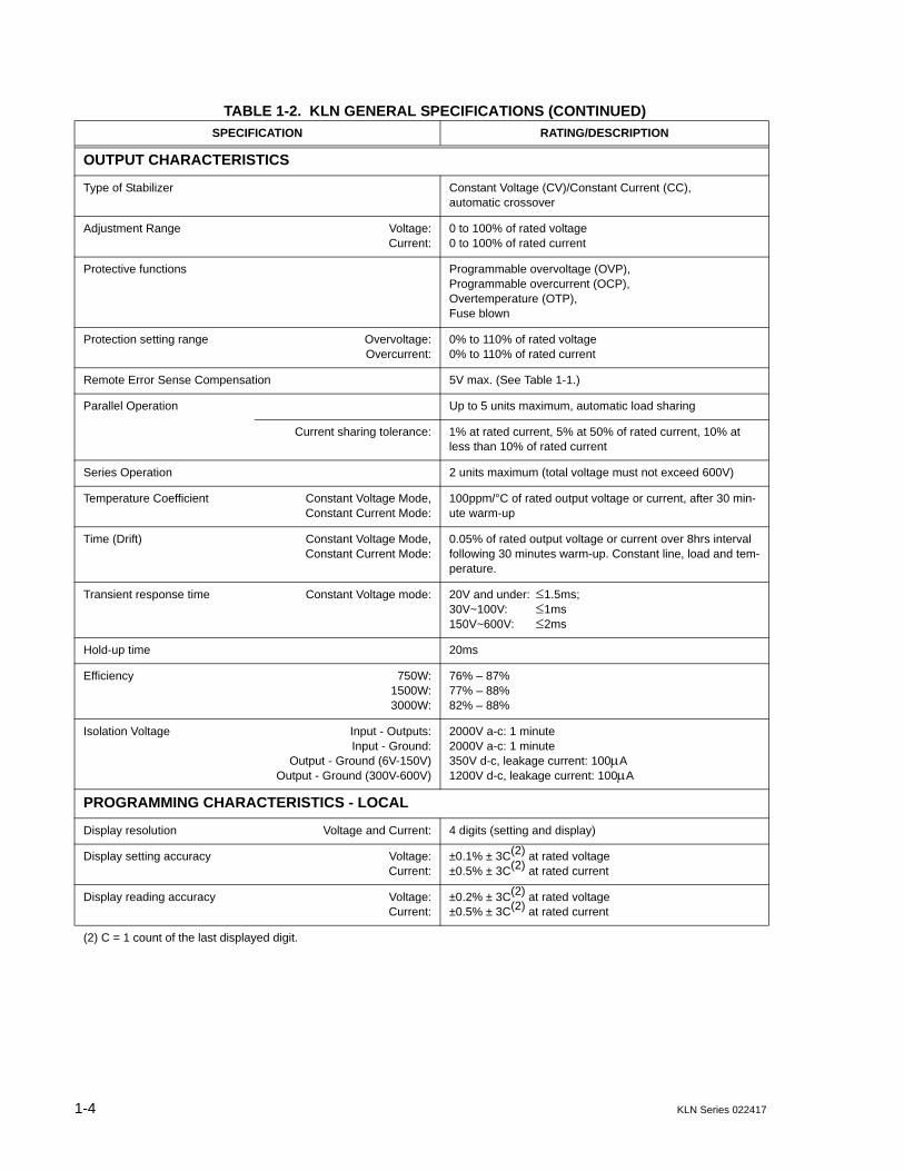
OUTPUT CHARACTERISTICS
Type of Stabilizer Constant Voltage (CV)/Constant Current (CC), automatic crossover
Adjustment Range Voltage:Current:
0 to 100% of rated voltage0 to 100% of rated current
Protective functions Programmable overvoltage (OVP), Programmable overcurrent (OCP), Overtemperature (OTP), Fuse blown
Protection setting range Overvoltage:Overcurrent:
0% to 110% of rated voltage0% to 110% of rated current
Remote Error Sense Compensation 5V max. (See Table 1-1.)
Parallel Operation Up to 5 units maximum, automatic load sharing
Current sharing tolerance: 1% at rated current, 5% at 50% of rated current, 10% at less than 10% of rated current
Series Operation 2 units maximum (total voltage must not exceed 600V)
Temperature Coefficient Constant Voltage Mode,Constant Current Mode:
100ppm/°C of rated output voltage or current, after 30 min-ute warm-up
Time (Drift) Constant Voltage Mode,Constant Current Mode:
0.05% of rated output voltage or current over 8hrs interval following 30 minutes warm-up. Constant line, load and tem-perature.
Transient response time Constant Voltage mode: 20V and under: 1.5ms;30V~100V: 1ms150V~600V: 2ms
Hold-up time 20ms
Efficiency 750W:1500W:3000W:
76% – 87%77% – 88%82% – 88%
Isolation Voltage Input - Outputs:Input - Ground:
Output - Ground (6V-150V)Output - Ground (300V-600V)
2000V a-c: 1 minute2000V a-c: 1 minute350V d-c, leakage current: 100A1200V d-c, leakage current: 100A
PROGRAMMING CHARACTERISTICS - LOCAL
Display resolution Voltage and Current: 4 digits (setting and display)
Display setting accuracy Voltage:Current:
±0.1% ± 3C(2) at rated voltage±0.5% ± 3C(2) at rated current
Display reading accuracy Voltage:Current:
±0.2% ± 3C(2) at rated voltage±0.5% ± 3C(2) at rated current
(2) C = 1 count of the last displayed digit.
TABLE 1-2. KLN GENERAL SPECIFICATIONS (CONTINUED)
SPECIFICATION RATING/DESCRIPTION

KLN Series 022417 1-5
PROGRAMMING CHARACTERISTICS - DIGITAL
Command setting resolution ±0.002% of full scale
Command reading resolution ±0.002% of full scale
Command and D/A setting accuracy
Voltage:Current:
±0.1% ± 3C(3) at rated voltage±0.5% ± 3C(3) at rated current
Command and A/D Measurement accuracy
Voltage:Current:
±0.2% ± 2C(3) at rated voltage (Average Measurement)±0.5% ± 3C(3) at rated current (Average Measurement)
Command response time 20ms (After received)(4)
RS-485 Digital Interface (standard)
Baud rate: Select 4.8K, 9.6K, 19.2K, 38.4K, 57.6K, or 115K (max)
Max number of unitsconnected to bus:
254
Max. effective control distance: 1000 meters.
GPIB Digital Interface Optional
LAN Digital Interface Optional
PROGRAMMING CHARACTERISTICS - ANALOG
Analog setting accuracy
Constant Voltage mode (CV): Voltage:Current:
± 5%± 5%
Constant Current mode (CC): Voltage:Current:
± 5%± 5%
Analog monitor accuracy Rated voltage output: 10.00V ± 0.25V
Zero voltage output: 0.00V ± 0.25V
Rated current output: 10.00V ± 0.25V
Zero current output: 0.00V ± 0.25V
PHYSICAL CHARACTERISTICS
Weight 750W:1500W:3000W:
Less than 11.2 lbs (5.1 Kg)Less than 19.84 lbs (9.0 Kg)Less than 33.3 lbs (15.1 Kg)
Dimensions 750W:
1500W:
3000W:
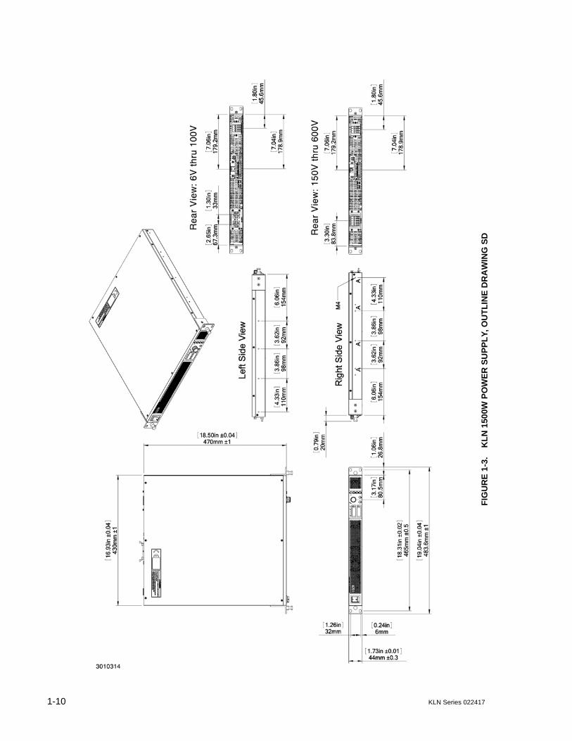
8.46"W x 1.73"H x 18.5"D (215mm x 44mm x 470mm)See Figure 1-216.93"W x 1.73H x 18.5"D (430mm x 44mm x 470mm)See Figure 1-316.93"W x 3.46"H x 18.5"D (430mm x 88mm x 470mm)See Figure 1-4
Source Power Connector 750W:1500W, 3000W:
IEC 320 inlet3-position terminal block
Load Connections 6V to 100V:150V to 600V (750W):
150V to 600V (1500W, 3000W):
± bus bars with protective cover5-position Euroblock4-position terminal block
(3) C = 1 count of the last displayed digit.(4) Programming time = Command response time + Output response time. The output response time differs for different models,
see Table 1-1. The analog programming input signal goes directly to the analog circuitry, so there is no command response time delay for analog programming.
TABLE 1-2. KLN GENERAL SPECIFICATIONS (CONTINUED)
SPECIFICATION RATING/DESCRIPTION
1-6 KLN Series 022417
PHYSICAL CHARACTERISTICS - CONTINUED
Programming Control port 26-pin connector
SER IN port 2-position Euroblock (mating connector supplied)
Sense port 3-position Euroblock (mating connector supplied)
RS-485 port 3-position Euroblock (mating connector supplied)
LAN port (optional) RJ 45 connector
GPIB port (optional) Standard IEEE 488.2 GPIB connector
GENERAL (ENVIRONMENTAL) SPECIFICATIONS
Temperature Operating:Storage:
0 to 50°C (indoor use) -20 to 70°C
Humidity Operating:Storage:
30%~90% RH (no condensation)10%~90% RH (no condensation)
Altitude 3000m max
Cooling Speed-Controlled Fans
Noise <70 dB (A)
EMC Standard EN 61326-1:2006
EMC Emissions (EN 61326-1) Conducted Disturbance: EN 55011:2007 +A2:2007 Class B
Radiated Disturbance: EN 55011:2007 +A2:2007 Class B
Harmonic Distortion: EN 61000-3-2:2006 Class A
Voltage Fluctuationsand Flicker:
EN 61000-3-3:2008 Section 5
EMC Immunity (EN 61326-1) Electrostatic Discharge (ESD): EN 61000-4-2:2009 Class B
Radiated RF Magnetic Field: EN 61000-4-3:2006 + A1:2008 + A2:2010 Class A
Electrical Fast Transients andBursts:
EN 61000-4-4:2004 + A1:2010 Class B
Surge: EN 61000-4-5:2006 Class B
Conducted DisturbanceInduced by RF Fields:
EN 61000-4-6:2009, Class A
Voltage Dips and ShortInterruptions:
EN 61000-4-11:2004, Class C
Vibration Testing (1 hour) Frequency:Acceleration:
PSD (Power Spectral Density:
Test Axis:
1Hz to 200Hz1.146g rms0.0001g2/Hz (1 Hz), 0.01g2/Hz (4 Hz, 100 Hz), 0.001g2/Hz (200 Hz)X/Y/-Z (10 mins.), +Z (30 mins.)
NOTE:All specifications apply after power on for 30 minutes, ambient temperature: 23±5°C, Humidity: under 80% RH, AC Voltage: ±5%, Frequency: ±5%.
TABLE 1-2. KLN GENERAL SPECIFICATIONS (CONTINUED)
SPECIFICATION RATING/DESCRIPTION
KLN Series 022417 1-7
FIG
UR
E 1
-2.
KL
N 7
50W
PO
WE
R S
UP
PL
Y, O
UT
LIN
E D
RA
WIN
G

1-8 KLN Series 022417
FIGURE 1-2. KLN 750W POWER SUPPLY, OUTLINE DRAWING (TWO UNITS MOUNTED IN RACK) (SHEET 1 OF 2)

KLN Series 022417 1-9
FIGURE 1-2. KLN 750W POWER SUPPLY, OUTLINE DRAWING (SHEET 2 OF 2)
NOTE: 150V MODELS SHOWN.
1-10 KLN Series 022417
FIG
UR
E 1
-3.
KL
N 1
500W
PO
WE
R S
UP
PL
Y, O
UT
LIN
E D
RA
WIN
G S
D

KLN Series 022417 1-11
FIG
UR
E 1
-4.
KL
N 3
000
W P
OW
ER
SU
PP
LY
, OU
TL
INE
DR
AW
ING
1-12 KLN Series 022417
1.4 LOCAL CONTROL
The front panel encoder can set and adjust output voltage and current under local control. Thedisplay uses two 4-digit LED displays to provide a digital readout of output voltage and current.
1.5 REMOTE CONTROL
The KLN Power Supply can be remotely controlled directly via the built-in RS-485 interfaceusing SCPI commands (see Appendix A and B). Most features available in local mode can alsobe accessed remotely via the RS-485 (standard), and GPIB (optional) or LAN (optional) digitalinterfaces. The transmission rate of RS-485 can be up to 115.2K bps. The RS-485 interface canbe used to connect multiple power supplies, up to a maximum of 254 units. The maximum effec-tive control distance can be up to 1000m.
Digital remote control is also available via optional GPIB (suffix G) and LAN (suffix E) interfaces.
1.6 ANALOG CONTROL
External reference signals, provided through the Programming Control port (see Table 2-4), canbe used to control the output voltage and current of the KLN. The Programming Control portallows control of output on/off and permits emergency shutdown of the output. Output signalsallow remote monitoring of whether the unit is powered on, output on/off, alarm condition, outputvoltage and current, and operating mode: Constant Current (CC) or Constant Voltage (CV).Refer to PAR. 3.5 for further details on using external signals to control and monitor the output.
1.7 FEATURES
1.7.1 DIGITAL CALIBRATION
The KLN Power Supply features high stability and long intervals between calibration. The unitcontains no user-required internal adjustments. Calibration is done by means of software (seeSection 4).
1.7.2 PROTECTION
The following protection is provided: OVP (Overvoltage protection), OCP (overcurrent protec-tion), OTP, (overtemperature protection) and blown fuse.
1.7.3 SAVING AND RECALLING SETTINGS
The KLN offers 16 memory locations accessible from the front panel that can be used to store aset of operating parameters for later use. For each location, the user can store voltage and cur-rent values. The stored settings can then be recalled to quickly program the unit to the predeter-mined setting. Refer to PAR. 3.3.6 and 3.3.7 for further details.
1.7.4 PARALLEL AND SERIES CONFIGURATIONS
Identical KLN units may be configured in series (up to two units including master) or parallel (upto five units including master) configurations. Parallel configurations provide for automatic cur-rent sharing (see PAR. 2.8 for details).

KLN Series 022417 1-13
1.7.5 MISCELLANEOUS FEATURES
• Both positive and negative output ramps can be independently programmed (see PAR’s.3.3.10 and 3.3.11).
• Last setting is automatically restored upon power-up. Output can be programmed to beeither on or off upon power-up (see PAR’s. 3.3.9).
• One key recall of up to 16 memory locations storing voltage and current settings (seePAR’s. 3.3.39 and 3.3.7).
• Variable speed fans reduce noise and extends fan life.
• Non-gap stacking; No ventilation holes at top or bottom.
• CE Mark approved.
• Approved as compliant to LXI Version 1.4, Device Specification 2011.
1.8 EQUIPMENT SUPPLIED
Equipment supplied with the KLN power supply is listed in Table 1-3.
TABLE 1-3. EQUIPMENT SUPPLIED
ITEM DESCRIPTIONKEPCO PART
NUMBER
Power Cable, (125V/15A) (750W only) Connects unit to 115V a-c source power. 118-0557
Power Cable (1500W, 3000W only) Connects unit to 230V a-c source power. 518-0120
Sense wires: Red (6V - 100V models) Used to connect output to local sensing connections: red: (+) to +S, black: (–) to –S
118-1302
Sense wires: Red (150V - 600V models) Used to connect output to local sensing connections: red: (+) to +S, black: (–) to –S
118-1304
Sense wires: Black (6V - 100V models) Used to connect output to local sensing connections: red: (+) to +S, black: (–) to –S
118-1303
Sense wires: Black (150V - 600V models) Used to connect output to local sensing connections: red: (+) to +S, black: (–) to –S
118-1305
Mating connectors (RS-485 and Sense) One supplied installed on RS-485 port to allow access to RS 485 interface; one supplied installed on Sense connector to provide access to sense connections used to compensate for voltage drop on load connections
542-0037
Programming Control Port cover Supplied installed on Programming Control port to protect programming port pins.
137-0155

1-14 KLN Series 022417
1.9 ACCESSORIES
Accessories (not supplied) for the KLN Power Supply are listed in Table 1-4.
SER IN mating connector Supplied installed on SER IN connector to allow series connection of two units.
542-0036
Output Terminal Protective Cover(750W, 6V-100V models only)
Used to protect output terminals during transit.
137-0156
Output Terminal Mating Connector (750W, 150V-600V models only)
Supplied installed on output terminals to allow convenient load connections.
142-0603
Rack Mount Kit (L-type Brackets (2) with mounting screws (4)(750W, 1500W models only)
Allows mounting of one 1U full rack KLN 1500W unit in standard 19-inch rack. 750W units require optional rack mounting Kit RA 81-1 or RA 81-2 to install one or two units, respectively, in 19-inch rack.
128-2428
Rack Mount Kit L-type Brackets (2) with mounting screws (6) (3000W models only)
Allows mounting of one 2U full-rack KLN 3000W unit in standard 19-inch rack.
128-2430
TABLE 1-4. ACCESSORIES
ITEM FUNCTION PART NUMBER
Rack Mount Kit(750W models only)
Allows mounting of one half-rack KLN 750W unit in standard 19-inch rack (L-type brackets supplied with unit, not included in Kit).
RA 81-1(Kepco)
Rack Mount Kit(750W models only)
Allows mounting of two half-rack KLN 750W units side-by-side in standard 19-inch rack (L-type brackets supplied with unit, not included in Kit).
RA 81-2(Kepco)
Parallel Connector Board
Provides convenient connections for parallel operation of up to five units
536-0129(Kepco)
Series Connector Board
Provides convenient connections for series operation of two units.
536-0130(Kepco)
Programming Port Cable
Provides connections between two programming ports for parallel and series operation.
518-0119(Kepco)
Side Support Bracket (pair), 14.95 in. long
Provides side support for rack-mounted units. Recommended for 3000W KLN Series.
RASA16BK3(Hammond)
Parallel Connection Cable (2 Units), 15cm long
Connects PROGRAMMING CONTROL port of two units to provide parallel connections without the need for a Parallel Connector Board.
518-0121(Kepco)
Chassis Slides Allows installation of full rack 1U and 2U KLN models in standard 19-inch wide cabinet (30 inches deep, minimum).
Model CS 07(Kepco)
TABLE 1-3. EQUIPMENT SUPPLIED (CONTINUED)
ITEM DESCRIPTIONKEPCO PART
NUMBER

KLN Series 022417 1-15/(1-16 Blank)
1.10 SAFETY
Service must be referred to authorized personnel. Using the power supply in a manner notspecified by Kepco. Inc. may impair the protection provided by the power supply. Observe allsafety precautions noted throughout this manual (see listing on Safety page A, preceding theTable of Contents). Table 1-5 lists symbols used on the power supply or in this manual whereapplicable.
TABLE 1-5. SAFETY SYMBOLS
SYMBOL Meaning
WARNING! RISK OF ELECTRIC SHOCK!
CAUTION: REFER TO REFERENCED PROCEDURE.
FRAME OR CHASIS TERMINAL
GROUND TERMINAL
PROTECTIVE GROUND CONDUCTOR TERMINAL
WARNING INDICATES THE POSSIBILITY OF BODILY INJURY OR DEATH.
CAUTION INDICATES THE POSSIBILITY OF EQUIPMENT DAMAGE.
!


KLN Series 022417 2-1
SECTION 2 - INSTALLATION
2.1 UNPACKING AND INSPECTION
This instrument has been thoroughly inspected and tested prior to packing and is ready foroperation. After careful unpacking, inspect for shipping damage before attempting to operate.Perform the preliminary operational check as outlined in PAR. 2.3. If any indication of damage isfound, file an immediate claim with the responsible transport service.
2.2 TERMINATIONS AND CONTROLS
a) Front Panel: Refer to Figure 3-1 (750W), 3-2 (1500W) or 3-3 (3000W) and Table 3-1.
b) Rear Panel: Refer to Figure 2-1 (750W), 2-2 (1500W) or 2-3 (3000W) and Table 2-1.
FIGURE 2-1. KLN 750W SERIES REAR PANEL
FIGURE 2-2. KLN 1500W SERIES REAR PANEL
FIGURE 2-3. KLN 3000W SERIES REAR PANEL

2-2 KLN Series 022417
FIGURE 2-4. LAN ETHERNET CONNECTOR (LAN INTERFACE ONLY)
FIGURE 2-5. RS-485 PORT
TABLE 2-1. REAR PANEL CONNECTOR FUNCTIONS
NUMBER(FIGURE 2-1,
2-2 or 2-3)CONNECTOR/TERMINAL FUNCTION
1RS-485
3-pin pluggable terminal block
Allows connection to RS-485 bus. See Table 2-2 for details.
2
Optional:either 24-pin GPIB
connector or LAN ethernet connector
(see Figure 2-4)
Allows connection to GPIB bus or LAN (optional) when installed. See Table 2-3 for GPIB connector details. Green LAN status indicator blinks when IDN? query received, stays on steady to indicate normal LAN operation, and is off when not connected to the LAN or a LAN fault has occurred.
3 Programming Control PortAllows access to analog input/output signals that allow monitoring and control of the power supply by analog means. See Table 2-4 for pin assignments.
4 SER INProvides output voltage reference from master to slave to ensure voltage slave matches the master when two units connected in series.
5 +S, –S Remote sensing voltage compensation.
6 DC Output Allows connection to load.
7 AC input Allows connection to mains supply using power cord supplied.
TABLE 2-2. RS-485 PORT INPUT/OUTPUT PIN ASSIGNMENTS
PIN(FIGURE 2-5)
SIGNAL NAME FUNCTION
G Ground Reduce external interference
+ +RX Connect to +TX of computer and/or +RX of next unit on RS-485 bus (see Figure 2-14).
– –RX Connect to –TX of computer and/or –RX of next unit on RS-485 bus (see Figure 2-14).
NOTE: Connect 120 Ohm termination resistor across + and – of last unit connected to RS-485 bus (furthest from computer)See PAR. 2.7.2.

KLN Series 022417 2-3
TABLE 2-3. GPIB (IEEE 488) PORT INPUT/OUTPUT PIN ASSIGNMENTS
PIN SIGNAL NAME FUNCTION
1 DI01 I/O Line
2 DI02 I/O Line
3 DI03 I/O Line
4 DI04 I/O Line
5 EOI End or Identify
6 DAV Data Valid
7 NRFD Not Ready for Data
8 NDAC Not Data Accepted
9 IFC Interface Clear
10 SRQ Service Request
11 ATN Attention
12 SHIELD Shield
13 DI05 I/O Line
14 DI06 I/O Line
15 DI07 I/O Line
16 DI08 I/O Line
17 REN Remote Enable
18 GND Ground (signal common)
19 GND Ground (signal common)
20 GND Ground (signal common)
21 GND Ground (signal common)
22 GND Ground (signal common)
23 GND Ground (signal common)
24 LOGIC GND Logic Ground
TABLE 2-4. PROGRAMMING CONTROL PORT I/O PIN ASSIGNMENTS
PIN(FIGURE 2-6)
SIGNAL NAME FUNCTION
1, 2 RECALL External recall control (dry contact). Same function as RCL key on front panel.
3, 4, 5, 6 --- Not used
7 Power on/off status Output signal. Active (low between pin 7 and pin 8) to indicate unit is turned on. (1)
8 Status common Common for Status signal pins 7, 9, 10, 11 and 12 (1)
9 Alarm statusOutput signal. Active (low between pin 9 and pin 8) to indicate whether alarm (OVP or OCP trips or shutdown signal applied to pin 23) has occurred. (open collector via optocou-pler). (1)
10 On/off statusOutput signal. Active (low between pin 10 and pin 8) to indicate output is on (open collector by optocoupler). (1) (See PAR. 3.3.38 to enable.)
11 CC statusOutput signal. Active (low between pin 11 and pin 8) to indicate unit is in constant current mode (open collector by optocoupler). (1)
12 CV statusOutput signal. Active (low between pin 12 and pin 8) to indicate unit is in constant voltage mode (open collector by optocoupler). (1)
13EXT +5V input
(isolated ON/OFF)
External input signal, isolated from input and output. External +5V signal (referenced to pin 14) turns output ON. Output is ON when activated by either pin 13 or pin 21. To activate this function, refer to PAR. 3.3.38 and set External Control of Output On/Off (Eo.C) to ON.
14 EXT V input common Common for Pin 13 (remote output on/off function).
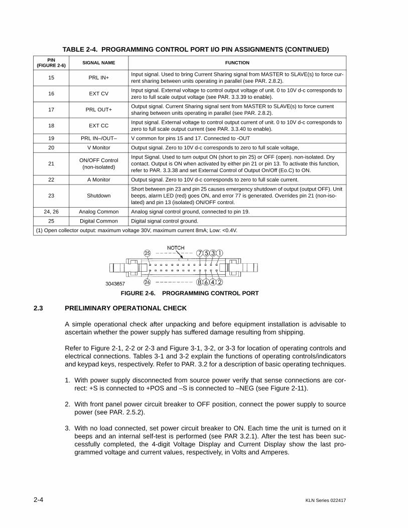
2-4 KLN Series 022417
FIGURE 2-6. PROGRAMMING CONTROL PORT
2.3 PRELIMINARY OPERATIONAL CHECK
A simple operational check after unpacking and before equipment installation is advisable toascertain whether the power supply has suffered damage resulting from shipping.
Refer to Figure 2-1, 2-2 or 2-3 and Figure 3-1, 3-2, or 3-3 for location of operating controls andelectrical connections. Tables 3-1 and 3-2 explain the functions of operating controls/indicatorsand keypad keys, respectively. Refer to PAR. 3.2 for a description of basic operating techniques.
1. With power supply disconnected from source power verify that sense connections are cor-rect: +S is connected to +POS and –S is connected to –NEG (see Figure 2-11).
2. With front panel power circuit breaker to OFF position, connect the power supply to sourcepower (see PAR. 2.5.2).
3. With no load connected, set power circuit breaker to ON. Each time the unit is turned on itbeeps and an internal self-test is performed (see PAR 3.2.1). After the test has been suc-cessfully completed, the 4-digit Voltage Display and Current Display show the last pro-grammed voltage and current values, respectively, in Volts and Amperes.
15 PRL IN+Input signal. Used to bring Current Sharing signal from MASTER to SLAVE(s) to force cur-rent sharing between units operating in parallel (see PAR. 2.8.2).
16 EXT CVInput signal. External voltage to control output voltage of unit. 0 to 10V d-c corresponds to zero to full scale output voltage (see PAR. 3.3.39 to enable).
17 PRL OUT+Output signal. Current Sharing signal sent from MASTER to SLAVE(s) to force current sharing between units operating in parallel (see PAR. 2.8.2).
18 EXT CCInput signal. External voltage to control output current of unit. 0 to 10V d-c corresponds to zero to full scale output current (see PAR. 3.3.40 to enable).
19 PRL IN–/OUT– V common for pins 15 and 17. Connected to -OUT
20 V Monitor Output signal. Zero to 10V d-c corresponds to zero to full scale voltage,
21ON/OFF Control
(non-isolated)
Input Signal. Used to turn output ON (short to pin 25) or OFF (open). non-isolated. Dry contact. Output is ON when activated by either pin 21 or pin 13. To activate this function, refer to PAR. 3.3.38 and set External Control of Output On/Off (Eo.C) to ON.
22 A Monitor Output signal. Zero to 10V d-c corresponds to zero to full scale current.
23 ShutdownShort between pin 23 and pin 25 causes emergency shutdown of output (output OFF). Unit beeps, alarm LED (red) goes ON, and error 77 is generated. Overrides pin 21 (non-iso-lated) and pin 13 (isolated) ON/OFF control.
24, 26 Analog Common Analog signal control ground, connected to pin 19.
25 Digital Common Digital signal control ground.
(1) Open collector output: maximum voltage 30V, maximum current 8mA; Low: <0.4V.
TABLE 2-4. PROGRAMMING CONTROL PORT I/O PIN ASSIGNMENTS (CONTINUED)
PIN(FIGURE 2-6)
SIGNAL NAME FUNCTION

KLN Series 022417 2-5
4. Press SHIFT/LOCAL key. Verify blue LED goes on. Press V/OVP key: Least significantdigit of Voltage Display and integral red OVP LED at the right of the display blink. Verifyblue LED goes off.
5. Rotate encoder to change the digits for adjustment. Turn clockwise to increase the value,counterclockwise to decrease the value. Tap encoder to move to the next digit. Continue untilthe maximum OVP value is displayed (e.g., 33.00 for 30V model).
6. Press ENTER key to accept programmed OVP value.
7. Press SHIFT/LOCAL key. Verify blue LED goes on. Press A/OCP. Least significant digitof Current Display and integral red OCP LED at the right of the display blink. Verifyblue LED goes off.
8. Rotate encoder to change the digits for adjustment. Turn clockwise to increase the value,counterclockwise to decrease the value. Tap encoder to move to the next digit. Continue untilthe maximum OCP value is displayed (e.g., 26.25 for 25 Ampere model).
9. Press ENTER key to accept programmed OCP value.
10.Press V/OVP key. Least significant digit of Voltage Display blinks.
11.Rotate encoder to change the digits for adjustment. Turn clockwise to increase the value,counterclockwise to decrease the value. Tap encoder to move to the next digit. Continue untilthe rated output voltage value (e.g., 30.00 for 30V model) is displayed.
12.Press ENTER key to accept programmed voltage value.
13.Press A/OCP key. Least significant digit of Current Display blinks.
14.Rotate encoder to change the digits for adjustment. Turn clockwise to increase the value,counterclockwise to decrease the value. Tap encoder to move to the next digit. Continue untila value of several Amperes of output current is displayed.
15.Connect a digital voltmeter (DVM) to the (+S) and (-S) terminals on the rear panel. Verify thatDVM shows there is no output voltage from the power supply.
16.Press green OUT key. Verify that green LED at left of OUT key goes on.
17.Compare the programmed output voltage value (e.g., 30.00V for 30V model per step 11) withthe voltage reading of the DVM; Verify that the difference between the two does not exceed±0.1% ± 3C(*).
18.Compare the voltage reading of Voltage Display with that of the DVM; Verify that the differ-ence between the two does not exceed ±0.2% ± 3C(*).
19.Disable the output by pressing the OUT key; verify front panel Voltage and Current displaysshow programmed values of Voltage and Current, respectively and DVM reads 0V.
20.Set power switch to OFF. The unit issues a long beep as it powers down. Disconnect unitfrom source power, then disconnect test equipment.
(*) C = 1 count of the last displayed digit.

2-6 KLN Series 022417
2.4 INSTALLATION
2.4.1 RACK MOUNTING 750W MODELS
One or two (side by side) KLN 750W units can be mounted in a standard 19-inch rack (see Fig-ure 1-2 for outline dimensions). The units are 1U high and do not require any gaps betweenequipment above and below. Airflow is front to back only. Use the optional RA 81-1 Mounting Kit(see Table 1-5) to mount a single unit. Use optional Mounting Kit RA 81-2 (see Table 1-5) tomount two half-rack units side by side in a 19-inch rack.
2.4.1.1 MOUNTING ONE 750W 1/2-RACK UNIT IN 19-INCH RACK
1. On one side of the unit, mount one L-type bracket with knob (supplied with unit) to the unitusing two screws supplied with unit.
2. Mount the U-type bracket supplied in the Kit to the other side of the unit using two screwssupplied in Kit.
3. Mount the other L-type bracket with knob (supplied with unit) to the end of the U-type bracketusing two screws supplied with unit. The knobs can now be used to support the assembledunit while installing in a 19-inch rack.
FIGURE 2-7. MOUNTING ONE KLN 750W UNIT IN 19-INCH RACK
2.4.1.2 MOUNTING TWO 750W 1/2-RACK UNITS IN 19-INCH RACK
To mount two KLN 750W units side-by-side in a 19 inch rack, use the RA 81-2 mounting kit (notsupplied, see Accessories, Table 1-5).
1. Place the two units side by side as they would be installed in the rack. On the outer side ofeach unit (not facing the other unit), mount one L-type bracket with knob (supplied with unit)to each unit using two screws supplied with unit for each (see Figure 1-2).

KLN Series 022417 2-7
2. Separate the two units. Install two shoulder screws, flat washers and lockwashers (suppliedwith Kit) at two locations on one unit (two threaded holes, A, Figure 1-2).
3. Move the two units together and insert the shoulder screws into the keyhole-shaped openingin the other unit (two holes, B, Figure 1-2). Then slide the unit without the shoulder screwsforward until the front panels of both units are flush.
4. Connect the two units at the rear using linking bracket (see Figure 1-2, sheet 2) and twoscrews supplied with Kit. The two units can now be handled as an assembly and can beinstalled directly into a 19-inch rack.
2.4.2 RACK MOUNTING 1500W MODELS
KLN 1500W units can be mounted in a standard 19-inch rack using the Mounting Kit suppliedwith the unit (see Figure 1-3 for outline dimensions). Knobs are preassembled to the two L-typebrackets using two screws supplied in the kit. On each side of the unit, attach the two L-typebrackets with knobs to the unit using four screws supplied in the Kit. The units are 1U high anddo not require any gaps between equipment above and below. Airflow is front to back only.
2.4.3 RACK MOUNTING 3000W MODELS
KLN 3000W units can be mounted in a standard 19-inch rack using the Mounting Kit suppliedwith the unit (see Figure 1-4 for outline dimensions). On each side of the unit, attach the two L-type brackets with handles to the unit using six screws supplied in the Kit. The units are 2U highand do not require any gaps between equipment above and below. Airflow is front to back only.Side support brackets (not supplied, see Table 1-4, Accessories) are recommended to supportthe weight of the unit.
2.5 WIRING INSTRUCTIONS
Interconnections between an a-c power source and a power supply, and between the powersupply and its load are as critical as the interface between other types of electronic equipment.If optimum performance is expected, certain rules for the interconnection of source, power sup-ply and load must be observed by the user. These rules are described in detail in the followingparagraphs.
CAUTION: WHEN WORKING WITH ACTIVE LOADS, THE VOLTAGE OR CURRENT OFTHE ACTIVE LOAD MUST NOT EXCEED THE MAXIMUM VOLTAGE OR CUR-RENT RATING OF THE KLN. OTHERWISE THE OVERVOLTAGE OR OVER-CURRENT PROTECTION WILL SHUT DOWN THE POWER SUPPLY.
2.5.1 SAFETY GROUNDING
To minimize shock hazard, the product chassis must be connected to an electrical ground. Theproduct must be connected to the AC power supply mains through a three-conductor powercable, with the ground wire firmly connected to an electrical ground (safety ground) at the poweroutlet.
Local, national and international safety rules dictate the grounding of the metal cover and caseof any instrument connected to the a-c power source, when such grounding is an intrinsic part ofthe safety aspect of the instrument. The ground terminal of the source power connector (Figure2-1) is connected to the chassis and the instructions below suggest wiring methods which com-ply with these safety requirements. In the event that the specific installation for the power sys-tem is different from the recommended wiring, it is the customer's responsibility to ensure that

2-8 KLN Series 022417
all applicable electric codes for safety grounding requirements are met. As a precaution, alwaysconnect the screw marked at the rear panel to proper earth ground.
2.5.2 SOURCE POWER CONNECTIONS
Source power is connected to the power supply via three-wire input power using the sourcepower cable supplied (see Table 1-4). See Table 1-2 for source power specifications. This powersupply operates from single phase a-c mains power (or between two phases of 3-phase a-cmains power) over the specified voltage and frequency ranges (Table 1-2) without any need forrange selection.
CAUTION: DO NOT USE AC SUPPLY WHICH EXCEEDS THE INPUT VOLTAGE AND FRE-QUENCY RATING OF THIS INSTRUMENT. THE INPUT VOLTAGE AND FRE-QUENCY RATING OF THE POWER SUPPLY ARE SHOWN IN TABLE 1-2. FORSAFETY REASONS, THE MAINS SUPPLY VOLTAGE FLUCTUATIONS MUSTNOT EXCEED ±10% OF NOMINAL VOLTAGE.
2.5.3 D-C OUTPUT GROUNDING
Connections between the power supply and the load and sensing connections may, despite allprecautions such as shielding, twisting of wire pairs, etc., be influenced by radiated noise, or“noise pick-up”. To minimize the effects of this radiated noise the user should consider ground-ing one side of the power supply/load circuit. The success of d-c grounding requires carefulanalysis of each specific application, however, this recommendation can only serve as a generalguideline.
One of the most important considerations in establishing a successful grounding scheme is toavoid GROUND LOOPS. Ground loops are created when two or more points are grounded atdifferent physical locations along the output circuit. Due to the interconnection impedancebetween the separated grounding points, a difference voltage and resultant current flow issuperimposed on the load. The effect of this ground loop can be anything from an undesirableincrease in output noise to disruption of power supply and/or load operation. The only way toavoid ground loops is to ensure that the entire output/load circuit is fully isolated from ground,and only then establish a single point along the output/load circuit as the single-wire groundpoint.
The exact location of the “best” d-c ground point is entirely dependent upon the specific applica-tion, and its selection requires a combination of analysis, good judgement and some amount ofempirical testing. If there is a choice in selecting either the OUTPUT or COMMON output termi-nals of the power supply for the d-c ground point, both sides should be tried, and preferencegiven to the ground point producing the least noise. For single, isolated loads the d-c groundpoint is often best located directly at one of the output terminals of the power supply; whenremote error sensing is employed, d-c ground may be established at the point of sense leadattachment. In the specific case of an internally-grounded load, the d-c ground point is automat-ically established at the load.

KLN Series 022417 2-9
The (+) and (–) terminals of KLN power supplies are d-c isolated (“floating”) from the chassis inorder to permit the user maximum flexibility in selecting the best single point ground location.Care must be taken in measuring the ripple and noise at the power supply: measuring deviceswhich are a-c line operated can often introduce additional ripple and noise into the circuit.
There is, unfortunately, no “best” method for interconnecting the load and power supply. Individ-ual applications, location and nature of the load require careful analysis in each case. Ground-ing a single point in the output circuit can be of great importance. It is hoped that the precedingparagraphs will be of some assistance in most cases. For help in special applications or difficultproblems, consult directly with Kepco's Application Engineering Department.
2.5.4 POWER SUPPLY/LOAD INTERFACE
The general function of a voltage- or current-stabilized power supply is to deliver the rated out-put quantities to the connected load. The load may have any conceivable characteristic: it maybe fixed or variable, it may have predominantly resistive, capacitive or inductive parameters; itmay be located very close to the power supply output terminals or it may be a considerable dis-tance away. The perfect interface between a power supply and its load would mean that thespecified performance at the output terminals would be transferred without impairment to anyload, regardless of electrical characteristics or proximity to each other.
The stabilized d-c power supply is definitely not an ideal voltage or current source, and practicalinterfaces definitely fall short of the ideal. All voltage-stabilized power supplies have a finitesource impedance which increases with frequency, and all current-stabilized power supplieshave a finite shunt impedance which decreases with frequency. The method of interfacebetween the power supply output and the load must, therefore, take into account not only thesize with regard to minimum voltage drop, but the configuration with regard to minimizing theimpedance introduced by practical interconnection techniques (wire, bus bars, etc.). The seriesinductance of the load wire must be as small as possible as compared to the source inductanceof the power supply: although the error sensing connection to the load compensates for the d-cvoltage drop in the power leads, it cannot compensate for the undesirable output effects of thepower lead inductance. These lead impedances (both power and sensing leads) are especiallyimportant if the load: is constantly modulated or step-programmed; has primarily reactive char-acteristics; or where the dynamic output response of the power supply is critical to load perfor-mance.
2.5.5 LOAD CONNECTION - GENERAL
Power connections to the load are achieved via the +POS and –NEG DC OUTPUT terminalslocated on the rear panel. Terminal connections for low voltage models (6V to 100V) are shownin Figure 2-8 (750W), 2-9 (1500W) or 2-10 (3000W). The 300V and 600V models employ Euro-block-style terminal blocks that accept bare wire ends.
FIGURE 2-8. LOAD CONNECTION TERMINALS FOR 750W MODELS
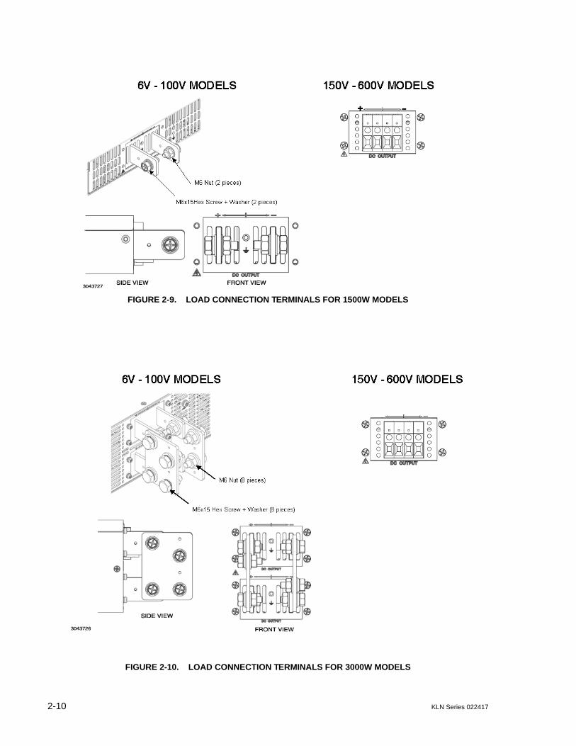
2-10 KLN Series 022417
FIGURE 2-9. LOAD CONNECTION TERMINALS FOR 1500W MODELS
FIGURE 2-10. LOAD CONNECTION TERMINALS FOR 3000W MODELS
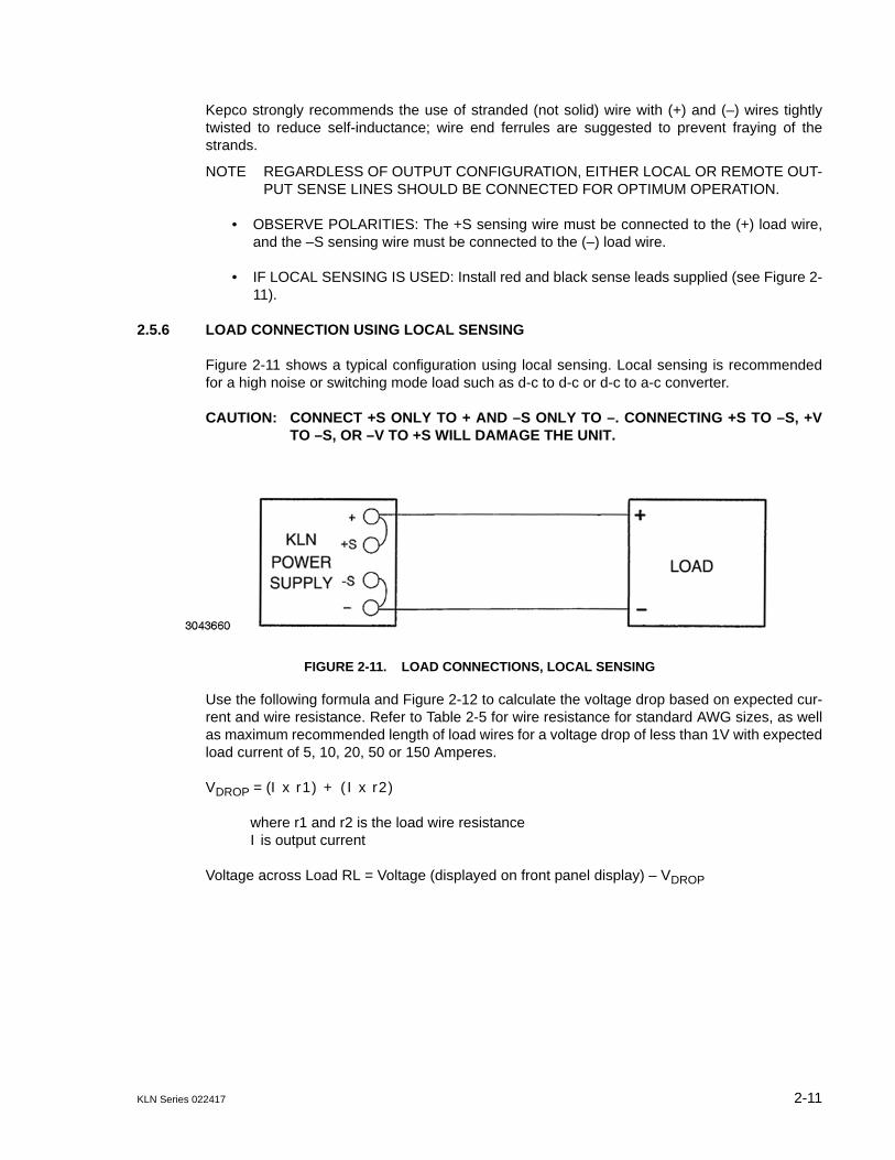
KLN Series 022417 2-11
Kepco strongly recommends the use of stranded (not solid) wire with (+) and (–) wires tightlytwisted to reduce self-inductance; wire end ferrules are suggested to prevent fraying of thestrands.
NOTE REGARDLESS OF OUTPUT CONFIGURATION, EITHER LOCAL OR REMOTE OUT-PUT SENSE LINES SHOULD BE CONNECTED FOR OPTIMUM OPERATION.
• OBSERVE POLARITIES: The +S sensing wire must be connected to the (+) load wire,and the –S sensing wire must be connected to the (–) load wire.
• IF LOCAL SENSING IS USED: Install red and black sense leads supplied (see Figure 2-11).
2.5.6 LOAD CONNECTION USING LOCAL SENSING
Figure 2-11 shows a typical configuration using local sensing. Local sensing is recommendedfor a high noise or switching mode load such as d-c to d-c or d-c to a-c converter.
CAUTION: CONNECT +S ONLY TO + AND –S ONLY TO –. CONNECTING +S TO –S, +VTO –S, OR –V TO +S WILL DAMAGE THE UNIT.
FIGURE 2-11. LOAD CONNECTIONS, LOCAL SENSING
Use the following formula and Figure 2-12 to calculate the voltage drop based on expected cur-rent and wire resistance. Refer to Table 2-5 for wire resistance for standard AWG sizes, as wellas maximum recommended length of load wires for a voltage drop of less than 1V with expectedload current of 5, 10, 20, 50 or 150 Amperes.
VDROP = (I x r1) + (I x r2)
where r1 and r2 is the load wire resistance I is output current
Voltage across Load RL = Voltage (displayed on front panel display) – VDROP
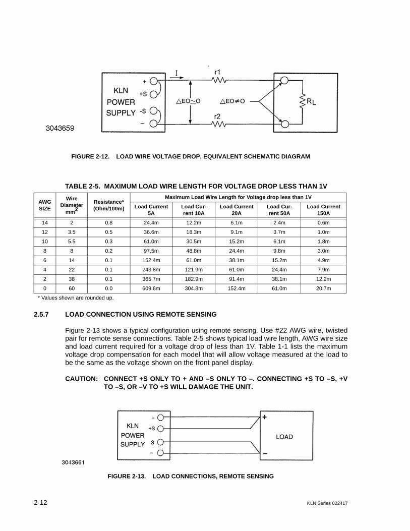
2-12 KLN Series 022417
FIGURE 2-12. LOAD WIRE VOLTAGE DROP, EQUIVALENT SCHEMATIC DIAGRAM
2.5.7 LOAD CONNECTION USING REMOTE SENSING
Figure 2-13 shows a typical configuration using remote sensing. Use #22 AWG wire, twistedpair for remote sense connections. Table 2-5 shows typical load wire length, AWG wire sizeand load current required for a voltage drop of less than 1V. Table 1-1 lists the maximumvoltage drop compensation for each model that will allow voltage measured at the load tobe the same as the voltage shown on the front panel display.
CAUTION: CONNECT +S ONLY TO + AND –S ONLY TO –. CONNECTING +S TO –S, +VTO –S, OR –V TO +S WILL DAMAGE THE UNIT.
FIGURE 2-13. LOAD CONNECTIONS, REMOTE SENSING
TABLE 2-5. MAXIMUM LOAD WIRE LENGTH FOR VOLTAGE DROP LESS THAN 1V
AWG SIZE
WireDiameter
mm2Resistance*(Ohm/100m)
Maximum Load Wire Length for Voltage drop less than 1V
Load Current5A
Load Cur-rent 10A
Load Current20A
Load Cur-rent 50A
Load Current 150A
14 2 0.8 24.4m 12.2m 6.1m 2.4m 0.6m
12 3.5 0.5 36.6m 18.3m 9.1m 3.7m 1.0m
10 5.5 0.3 61.0m 30.5m 15.2m 6.1m 1.8m
8 8 0.2 97.5m 48.8m 24.4m 9.8m 3.0m
6 14 0.1 152.4m 61.0m 38.1m 15.2m 4.9m
4 22 0.1 243.8m 121.9m 61.0m 24.4m 7.9m
2 38 0.1 365.7m 182.9m 91.4m 38.1m 12.2m
0 60 0.0 609.6m 304.8m 152.4m 61.0m 20.7m
* Values shown are rounded up.

KLN Series 022417 2-13
2.6 COOLING
The power devices used within the power supply are maintained within their operating tempera-ture range by means of internal heat sink assemblies and variable speed fans with air flow fromfront to back. There are no intake or exhaust ports at the top or bottom, permitting stacked rackmounting with no air gaps between stacked units. If the power supply is located within a confinedspace, take care that the ambient temperature, which is the temperature of the air immediatelysurrounding the power supply, does not rise above the specified limits (see Table 1-2).
2.7 SETTING UP THE UNIT
The following paragraphs describe the connections and initial KLN setup needed to operate inthe desired mode.
2.7.1 SETUP FOR LOCAL OPERATION
After connecting the unit using either local (PAR. 2.5.6) or remote sensing (PAR. 2.5.7), the unitwill power up in Local mode with no further setup required.
2.7.2 SETUP FOR REMOTE OPERATION VIA RS-485
CAUTION: DO NOT CONNECT THE POSITIVE OUTPUT TO GROUND WHEN RS-485 ISUSED. THERE IS A POTENTIAL SHOCK HAZARD AT THE RS-485 PORTWHEN POWER SUPPLIES ARE USED WITH RATED OR COMBINED VOLT-AGE GREATER THAN 400V AND THE POSITIVE OUTPUT OF THE POWERSUPPLY IS GROUNDED.
Connect the KLN to the controlling computer or to the previous unit in the RS-485 daisy chainper Figure 2-14. It is recommended that double shielded wire be used to ensure the quality ofremote communication. The last unit on the RS-485 bus requires a 120-Ohm terminating resis-tor as shown in Figure 2-14.
With all power off, connect the load to the KLN using either local or remote sensing (refer toPAR. 2.5). If units are to be connected in series or parallel, refer to PAR. 2.8.
Turn power on and refer to PAR. 3.2 for power supply basics. See PAR. 3.3.16 to establish RS-485 baud rate and PAR. 3.3.18 to establish the RS-485 Address.
SCPI programming is described in PAR. 3.7; Appendices A and B provide syntax for SCPI com-mon and subsystem commands and queries implemented in this unit. For RS-485 communica-tion the RS-485 address (Axx x) must precede every command. E.g., to set the brightness to 3and output voltage to 30 of a unit with RS-485 address 007, send A007DISP:CONT 3;:A007SOUR:VOLT 30

2-14 KLN Series 022417
FIGURE 2-14. RS-485 CONNECTIONS
2.7.3 SETUP FOR REMOTE OPERATION VIA USB)
Operation via a USB port is possible using the RS-485 port of the KLN and a commerciallyavailable USB to RS-485 adapter, isolated (not supplied) as shown in Figure 2-15. See PAR.2.7.2 and Figure 2-14 for RS-485 operation.
FIGURE 2-15. USB CONNECTIONS
2.7.4 SETUP FOR REMOTE OPERATION VIA GPIB (IEEE 488)
CAUTION: DO NOT CONNECT THE POSITIVE OUTPUT TO GROUND WHEN IEEE 488 ISUSED. THERE IS A POTENTIAL SHOCK HAZARD AT THE IEEE 488 (GPIB)PORT WHEN POWER SUPPLIES ARE USED WITH RATED OR COMBINEDVOLTAGE GREATER THAN 400V AND THE POSITIVE OUTPUT OF THEPOWER SUPPLY IS GROUNDED.
Operation via GPIB is possible if the optional GPIB interface is installed. With all power off, con-nect the load to the KLN using either local or remote sensing. If units are to be connected inseries or parallel, refer to PAR. 2.8. Connect the GPIB connector to a computer (ensure aproper GPIB interface card is installed in the computer) and the KLN GPIB port (see Figure 2-16). Turn power on and refer to PAR. 3.2 for power supply basics and PAR. 3.6 for digital remotemode programming. Verify GPIB communication using the utility software supplied by the man-ufacturer of the GPIB card installed in the computer.
Use I/O select (see PAR. 3.3.15) to select GPIB programming interface. The default GPIBaddress is 07; to change it refer to PAR 3.3.17. The unit automatically enters remote modewhen a command is accepted.
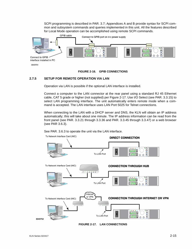
KLN Series 022417 2-15
SCPI programming is described in PAR. 3.7; Appendices A and B provide syntax for SCPI com-mon and subsystem commands and queries implemented in this unit. All the features describedfor Local Mode operation can be accomplished using remote SCPI commands.
FIGURE 2-16. GPIB CONNECTIONS
2.7.5 SETUP FOR REMOTE OPERATION VIA LAN
Operation via LAN is possible if the optional LAN interface is installed.
Connect a computer to the LAN connector at the rear panel using a standard RJ 45 Ethernetcable, CAT 5 grade or higher (not supplied) per Figure 2-17. Use I/O Select (see PAR. 3.3.15) toselect LAN programming interface. The unit automatically enters remote mode when a com-mand is accepted. The LAN interface uses LAN Port 5025 for Telnet connections.
When connecting to the LAN with a DHCP server and DNS, the KLN will obtain an IP addressautomatically; this will take about one minute. The IP address information can be read from thefront panel (see PAR. 3.3.21 through 3.3.36 and PAR. 3.3.45 through 3.3.47) or a web browser(see PAR 3.6.3).
See PAR. 3.6.3 to operate the unit via the LAN interface.
FIGURE 2-17. LAN CONNECTIONS

2-16 KLN Series 022417
2.8 MULTIPLE UNIT CONFIGURATIONS
Parallel and series configurations of identical KLN units increase the rated current or voltagerange of the power supply. Up to five units (including the master) can be connected in parallel toincrease the current: IMAX (one unit) x NP = IMAX (parallel combination) where NP = number of units inparallel. Similarly, up to two units (including the master) can be connected in series to increasethe voltage: EMAX (one unit) x N2 = EMAX (Series combination) where N2 = number of units in series.
2.8.1 SERIES CONNECTIONS
Two identical KLN units (one master, one slave) can be operated in series to double the outputvoltage.
CAUTION: TOTAL VOLTAGE MUST NOT EXCEED 600V TO AVOID DAMAGING THEUNITS.
See Figure 2-18A for series connections with local sensing or Figure 2-18B for series connec-tions with remote sensing. See PAR. 2.5.5 for guideline regarding load connections. See PAR.3.4.1 for instructions on operating units connected in series.
Connections for series operation can be simplified by using the optional Series ConnectorBoard (see Table 1-4) illustrated in Figures 2-18 and 2-19. If the optional Series ConnectorBoard is not used, refer to Figure 2-20 for programming port connections required for seriesoperation.
FIGURE 2-18. SERIES CONNECTIONS

KLN Series 022417 2-17
FIGURE 2-19. OPTIONAL SERIES CONNECTOR BOARD
FIGURE 2-20. PROGRAMMING CONTROL PORT CONNECTIONS FOR SERIES OPERATION
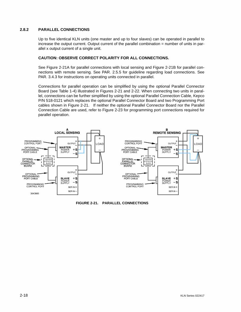
2-18 KLN Series 022417
2.8.2 PARALLEL CONNECTIONS
Up to five identical KLN units (one master and up to four slaves) can be operated in parallel toincrease the output current. Output current of the parallel combination = number of units in par-allel x output current of a single unit.
CAUTION: OBSERVE CORRECT POLARITY FOR ALL CONNECTIONS.
See Figure 2-21A for parallel connections with local sensing and Figure 2-21B for parallel con-nections with remote sensing. See PAR. 2.5.5 for guideline regarding load connections. SeePAR. 3.4.3 for instructions on operating units connected in parallel.
Connections for parallel operation can be simplified by using the optional Parallel ConnectorBoard (see Table 1-4) illustrated in Figures 2-21 and 2-22. When connecting two units in paral-lel, connections can be further simplified by using the optional Parallel Connection Cable, KepcoP/N 518-0121 which replaces the optional Parallel Connector Board and two Programming Portcables shown in Figure 2-21. If neither the optional Parallel Connector Board nor the ParallelConnection Cable are used, refer to Figure 2-23 for programming port connections required forparallel operation.
FIGURE 2-21. PARALLEL CONNECTIONS
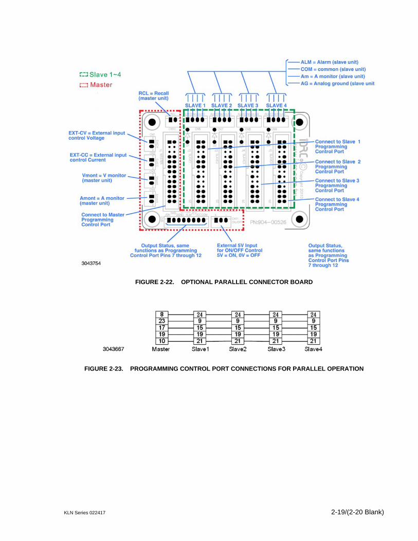
KLN Series 022417 2-19/(2-20 Blank)
FIGURE 2-22. OPTIONAL PARALLEL CONNECTOR BOARD
FIGURE 2-23. PROGRAMMING CONTROL PORT CONNECTIONS FOR PARALLEL OPERATION

KLN Series 022417 3-1
SECTION 3 - OPERATION
3.1 GENERAL
This section explains how to operate the KLN Power Supply. KLN Power Supplies feature threemodes of operation:
• Local Mode (see PAR. 3.3): This is the default operating mode, providing full access toall programming and readback functions via front panel displays, controls, and indica-tors.
• Analog Remote Mode (see PAR. 3.5): The unit can be controlled using analog signalsapplied via the Programming Control port, regardless of whether local or digital remote isactive.
• Digital Remote Mode (see PAR. 3.6): This mode is selected via commands transmittedthrough one of the digital ports. One port is for RS-485 port [standard models] The sec-ond port is optional: either an IEEE-488 (GPIB) (G-suffix models) port or a LAN port [E-Suffix models]. The port to be used must first be enabled using the Menu (see I/O Select,PAR. 3.3.15). The power supply automatically goes into digital remote mode when com-mands are accepted via one of the digital ports. All communication is via SCPI com-mands which afford full functionality of the KLN (see PAR. 3.7, Appendix A and AppendixB).
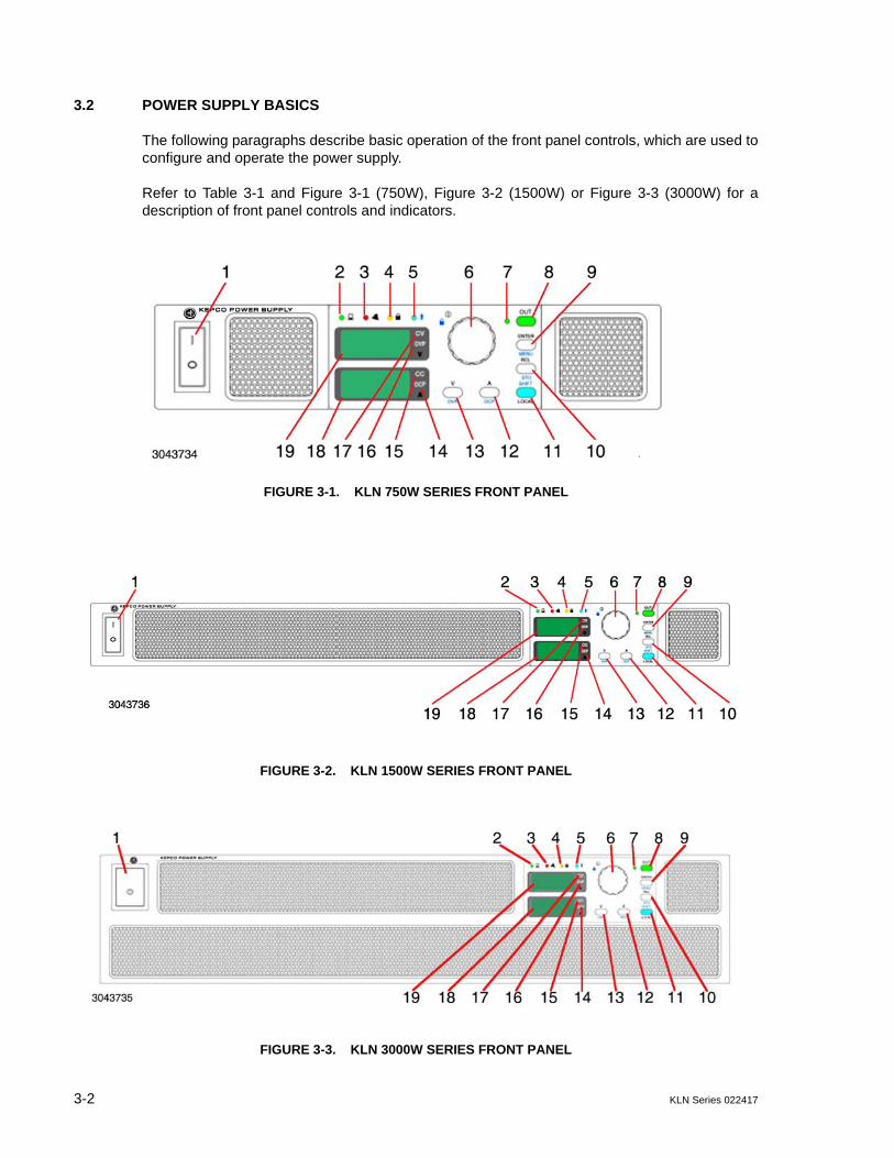
3-2 KLN Series 022417
3.2 POWER SUPPLY BASICS
The following paragraphs describe basic operation of the front panel controls, which are used toconfigure and operate the power supply.
Refer to Table 3-1 and Figure 3-1 (750W), Figure 3-2 (1500W) or Figure 3-3 (3000W) for adescription of front panel controls and indicators.
FIGURE 3-1. KLN 750W SERIES FRONT PANEL
FIGURE 3-2. KLN 1500W SERIES FRONT PANEL
FIGURE 3-3. KLN 3000W SERIES FRONT PANEL

KLN Series 022417 3-3
TABLE 3-1. FRONT PANEL CONTROLS AND INDICATORS
NUMBER(FIGURE 3-1)
CONTROL/INDICATOR FUNCTION
1POWER ON/OFF
circuit breaker A7CB1Applies source power to unit
2REMOTE
status LEDGreen LED, lights when unit is under remote control. Press SHIFT/LOCAL key to restore local control.
3ALARM
status LED
Red LED, lights if a) OVP, OCP or OTP are triggered, b) command error, c) front panel operation error, d) emergency shutdown, or e) power supply failure. Refer to Table B-2 for an explanation of error codes.
4KEYLOCKstatus LED
Yellow LED, lights when front panel keys are locked. To lock the front panel keys and encoder, press SHIFT and tap the encoder. Repeat to unlock the front panel.
5SHIFT
status LEDBlue LED, lights when SHIFT mode is active.
6 EncoderThe encoder Increases (clockwise) or decreases (counterclockwise) the highlighted digit of the Voltage or Current display, then press ENTER key to confirm. Tap the encoder to change the highlight. The highlighted digit blinks slowly.
7Output ON/OFF
status LEDGreen LED, lights when output is on.
8OUT on/off
key
Output ON/OFF enable/disable. The DC power output will be set to OFF automati-cally in the following situations:a. Power on setting (PAR 3.3.9) is set to OFF and:
1) Restart of the AC input. (See PAR. 3.3.9 to configure whether unit powers up with out off at previous setting.)
2). The mains supply is interrupted for more than 100mS.3) The mains supply exceeds or is under the rated input range more than 500ms.
b. If OCP - OVP - OTP are detected.
9ENTER/MENU
dual function key
a. Press ENTER to confirm value set by encoder.b. Press SHIFT+ENTER to get access to MENU function. See PAR. 3.2.2c. When output is ON, only limited Menu functions can be changed (see PAR. 3.3.5).
10RCL/STO
dual function key
A maximum of 16 memory settings can be stored or recalled. See PAR’s. 3.3.6 and 3.3.7 for details.a. Press RCL as many times as needed to view the stored voltage/current settings in sequence, press ENTER to confirm recall, press V to exit recall function.b. Press SHIFT + STO to store settings. Rotate encoder to scroll through memory cells. Press ENTER to store programmed voltage and current settings, press ENTER to exit storage function.
11SHIFT/LOCAL
dual function key
When unit is operated manually in local mode, this key functions as a SHIFT key. When blue LED is ON, the functions noted in blue text for the front panel keys can accessed when SHIFT is pressed. b. When the unit is remote controlled, only the LOCAL key is functional; press this key to exit remote control and restore local front panel operation.
12 A/OCP
dual function key
a. Press A/OCP key to adjust the A set current value: the last digit of the Current dis-play will be blinking. Turn the encoder to adjust the value of the blinking digit. Tap the encoder to go to the next digit. Press ENTER to confirm. A cannot be set more than programmed value of OCP.b. To set OCP press SHIFT key, then press A/OCP key. Use encoder and ENTER to set OCP. OCP cannot be set less than programmed value of A.
13 V/OVP
dual function key
a. Press V/OVP key to adjust the V set voltage value: the last digit of the Voltage dis-play will be blinking. Turn the encoder to adjust the value of the blinking digit. Tap the encoder to go to the next digit. Press ENTER to confirm. V cannot be set more than programmed value of OVP.b. To set OVP press SHIFT key, then press V/OVP key. Use encoder and ENTER to set OVP. OVP cannot be set less than programmed value of V.
14 OCP indicatorOvercurrent Protection indicator. Lights if overcurrent has occurred. Blinks while set-ting overcurrent protection.
15 CC indicator Lights when unit is in Constant Current mode

3-4 KLN Series 022417
FIGURE 3-4. 7-SEGMENT DISPLAY CHARACTERS
3.2.1 TURNING THE POWER SUPPLY ON
1. To turn the power supply on, set POWER ON/OFF circuit breaker (1, Figure 2-1) to ON.Apply firm, continuous pressure to rocker actuator until fully engaged.
2. When the power supply is turned on, it beeps and performs a self-test which sequentiallychecks the power status, PFC module (DC bus voltage), A/D converter, display board,SENSE status, and EEPROM.
3. While the self-test is in process, the following occurs:
• For 1 second all the indicators on the front panel are lit.
• For 1.6 seconds the Voltage display shows rated voltage and the Current displayshows rated current. The rest of the indicators are unlit and the digital and analog inter-faces are temporarily disabled.
• For 1.2 seconds the Voltage display shows Hx.xx (hardware version) and the Currentdisplay shows Fx.xx (firmware version). The rest of the indicators are still unlit.
• For 1.2 seconds the Voltage display shows Ax.xx (Main Control version) and Currentdisplay shows Dx.xx (display board version). The rest of the indicators are still unlit.
4. When the self-test is complete, the Voltage display shows the last voltage setpoint value andthe Current display shows the last current setpoint value. All the front panel keys are func-tional and the remote-controlled functions can be enabled.
16 OVP indicatorOvervoltage Protection indicator. Lights if overvoltage error has occurred. Blinks while setting overvoltage protection value.
17 CV indicator Lights when unit is in Constant Voltage mode
18Current Display
4 digit LED
Displays output current or setting value in Amperes. CC indicator at right lights when unit is in constant current mode. OCP indicator lights if overcurrent error has occurred. OCP blinks while setting OCP value. Refer to Figure 3-4 to translate limited 7-segment display characters into standard alphanumeric characters.
19Voltage Display
4 digit LED
Displays output voltage or setting value in Volts. CV indicator at right lights when unit is in constant voltage mode. OVP indicator lights if overvoltage error has occurred. OVP blinks while setting OVP value. Refer to Figure 3-4 to translate limited 7-seg-ment display characters into standard alphanumeric characters.
TABLE 3-1. FRONT PANEL CONTROLS AND INDICATORS (CONTINUED)
NUMBER(FIGURE 3-1)
CONTROL/INDICATOR FUNCTION

KLN Series 022417 3-5
• If an error occurs, the red (alarm) LED goes on. Refer to PAR. 3.3.50 to view theerror code.
5. When the unit is turned on for the first time, the factory default conditions upon power upafter a successful self test are as shown in Table 3-2.
TABLE 3-2. FACTORY DEFAULTS
Parameter Factory Default
Output V 10% of rated voltage (0V for E- or G- suffix models)
Output C 10% of rated current (0A for E- or G- suffix models)
OVP 110% of rated Voltage
OCP 110% of rated Current
Output: On/off OFF
Power On: LAST/OFF OFF
RAMP UP time 0.1
RAMP down time 0
Undervoltage Limit 0
BEEP: On/Off On
I/O Select RS 485
RS 485 Baud rate 115200
GPIB address 07
RS 485 address 007
Parallel/Series: PM/PS/SM/SS PM
External Control of output: ON/OFF OFF
Voltage Control: LOC/EXT LOC
Current Control: LOC/EXT LOC
Front panel lockout OFF
Voltage Set: Direct/Enter Direct
DHCP: On/Off On
SYST:COMM:LAN:GATE DHCP On: from DHCP server DHCP Off: 0.0.0.0
SYST:COMM:LAN:IP DHCP On: From DHCP serverDHCP Off: 192.168.0.100
SYST:COMM:LAN:IPAD 192.168.0.100
SYST:COMM:LAN:SMAS 255.255.255.0
SYST:COMM:LAN:MAC 70-46-42-XX-XX-XX
SYST:COMM:LAN:TEL:PORT 5025
NOTES:(1) Parameters changed via front panel are saved when unit is powered off, and will be restored upon power-up.
Parameters changed via SCPI command are not saved when unit is turned off and are restored to the last value entered from front panel when power is cycled on.
(2) *RST resets the following: Output to OFF, Output V to 0V, Output A to 0A, OVP to 110% of rated voltage, OCP to 110% of rated current, Undervoltage Limit to 0, and front panel lockout to OFF. All other parameters shown above are restored to the last value entered from front panel.
(3) Cycling power resets the following: Output to setting determined by Power On setting (see PAR. 3.3.9), Under-voltage Limit to 0 and front panel lockout to OFF. All other parameters shown above are restored to the last value entered from front panel.
(4) RST1 resets the IP address to 192.168.0.100/255.255.0.0 and clears the Gateway and DNS settings.(5) Parameters for options are defined only when applicable (see Table 3-3).
3-6 KLN Series 022417
3.2.2 MENU STRUCTURE
Many of the KLN functions are accessed via MENU mode (see Table 3-3 for complete list ofMENU functions).
1. Press SHIFT key to enter SHIFT mode. Verify blue LED lights, then press ENTER key toenter MENU mode.
NOTE: Only limited Menu functions can be changed if the output is set to ON (see PAR. 3.3.5).
2. Rotate encoder to select MENU functions. Functions are displayed in the order shown inTable 3-3. Menu functions are shown in the Voltage display and the corresponding value ofthe function is shown in the Current display.
3. When the desired MENU function is shown in the Voltage display, press ENTER key toaccess the selected function and setting.
4. To change the digit tap the encoder. The highlighted digit can be changed by rotating theencoder. Tap the encoder to move to the next digit. When the setting is complete pressENTER key to confirm.
5. Rotate encoder to move to the next MENU function.
6. Press SHIFT key to enter SHIFT mode. Verify blue LED lights, then press ENTER key toleave MENU mode.
3.3 LOCAL MODE OPERATION
Local operation of the KLN power supply is accomplished from the front panel via the front panelkeys and the encoder. All indications are provided by the two 4-digit LED displays, each with twointegral status indicators, and five front panel status LEDs.
3.3.1 SETTING LOCAL/REMOTE MODE
When the power supply is turned on, it is automatically set to Local mode. If digital remote modeis active, the (REMOTE indicator is lit) the unit can be restored to local mode by pressingthe SHIFT/LOCAL (LOCAL) key on the front panel.
NOTE: It is recommended that the unit be reset (see PAR. 3.3.48) when changing from digitalremote to local control to avoid conflicts with digital commands.
After the desired port (GPIB, RS-485, or LAN) has been selected (see PAR. 3.3.15), the powersupply will automatically go into digital remote mode when digital remote commands areaccepted. Analog remote control signals via the Programming Control port (see Table 2-4) areavailable when enabled (see PAR. 3.3.39 for voltage control, PAR. 3.3.40 for current control).Analog status signals from the Programming Control port are always available.

KLN Series 022417 3-7
TABLE 3-3. MENU FUNCTIONS
Voltage Display Current Display Description Reference
ERR 000 ~ 999 Error Code PAR. 3.3.50
OUT DIR or ENT Output Mode Setting PAR. 3.3.8
P.ON LAST or OFF Power ON Mode PAR. 3.3.9
R.UPT 00.0 ~99.9 Ramp Up Time PAR. 3.3.10
R.DNT 00.0 ~99.9 Ramp Down Time PAR. 3.3.11
MEM.F 01 ~ 16 Memory Flag PAR. 3.3.12
BEEP ON or OFF Key Beep On/Off PAR. 3.3.13
BRIT 0 ~ 5 Display Brightness PAR. 3.3.14
I.O 485 or GPIB(1) or LAN(2)
Interface Select PAR. 3.3.15
485 4.8K, 9.6K, 19.2K, 38.4K, 57.6K,
115.2K
RS-485 baud rate PAR. 3.3.16
GPIB(1) 00 ~ 30 GPIB Address PAR. 3.3.17
485 A001 ~ A254 RS-485 Address PAR. 3.3.18
DHCP(2) OFF or ON DHCP function PAR. 3.3.19
DNS OFF or ON DNS function PAR. 3.3.20
S.IP1/V.IP1(2) 001 ~ 223 Set (if DHCP is OFF) or view (if DHCP is ON) part 1 of IP Address PAR. 3.3.21
S.IP2/V.IP2(2) 001 ~ 254 Set (if DHCP is OFF) or view (if DHCP is ON) part 2 of IP Address PAR. 3.3.22
S.IP3/V.IP3(2) 001 ~ 254 Set (if DHCP is OFF) or view (if DHCP is ON) third IP part of Address PAR. 3.3.23
S.IP4/V.IP4(2) 001 ~ 254 Set (if DHCP is OFF) or view (if DHCP is ON) fourth IP part of Address PAR. 3.3.24
S.MN1/V.MN1(2) 000 ~ 255 Set (if DHCP is OFF) or view (if DHCP is ON) part 1 of Subnet Address
PAR. 3.3.25
S.MN2/V.MN2(2) 000 ~ 255 Set (if DHCP is OFF) or view (if DHCP is ON) part 2 of Subnet Address
PAR. 3.3.26
S.MN3/V.MN3(2) 000 ~ 255 Set (if DHCP is OFF) or view (if DHCP is ON) part 3 of Subnet Address
PAR. 3.3.27
S.MN4/V.MN4(2) 000 ~ 255 Set (if DHCP is OFF) or view (if DHCP is ON) part 4 of Subnet Address
PAR. 3.3.28
S.GW1/V.GW1(2) 001 ~ 223 Set (if DHCP is OFF) or view (if DHCP is ON) part 1 of Gateway Address
PAR. 3.3.29
S.GW2/V.GW2(2) 001 ~ 254 Set (if DHCP is OFF) or view (if DHCP is ON) part 2 of Gateway Address
PAR. 3.3.30
S.GW3/V.GW3(2) 001 ~ 254 Set (if DHCP is OFF) or view (if DHCP is ON) part 3 of Gateway Address
PAR. 3.3.31
S.GW4/V.GW4(2) 001 ~ 254 Set (if DHCP is OFF) or view (if DHCP is ON) part 4 of Gateway Address
PAR. 3.3.32
S.DN1/V.DN1(2) 001 ~ 223 Set (if DNS is OFF) or view (if DNS is ON) part 1 of DNS Address PAR. 3.3.33
S.DN2/V.DN2(2) 001 ~ 254 Set (if DNS is OFF) or view (if DNS is ON) part 2 of DNS Address PAR. 3.3.34
S.DN3/V.DN3(2) 001 ~ 254 Set (if DNS is OFF) or view (if DNS is ON) part 3 of DNS Address PAR. 3.3.35
S.DN4/V.DN4(2) 001 ~ 254 Set (if DNS is OFF) or view (if DNS is ON) part 4 of DNS Address PAR. 3.3.36
PSOP PM, PS, SM or SS Parallel Master, Parallel Slave, Series Master, Series Slave PAR. 3.3.37
EO.C OFF or ON External On/Off control enable/disable PAR. 3.3.38
CV.M LOC or EXT Voltage set, either LOC (Local) using the front panel or EXT (External) using the analog signal from the Programming Control port.
PAR. 3.3.39
(1) Only if optional GPIB interface installed. (2) Only if optional LAN interface installed.

3-8 KLN Series 022417
3.3.1.1 FRONT PANEL LOCKOUT
To prevent unauthorized setting of the power supply, KEYLOCK can be enabled which disablesthe front panel keys and the encoder.
Press SHIFT key to enter SHIFT mode ( LED lit), then tap the encoder to enable KEYLOCK.The yellow indicator goes on and all the front panel keys (except SHIFT) and the encoderare disabled.
To exit KEYLOCK tap the encoder while in SHIFT mode ( LED lit).
3.3.2 SET VOLTAGE OR OVERVOLTAGE PROTECTION (OVP)
The maximum setting for voltage is 105% of rated voltage and cannot be adjusted to exceed theOVP setting. The maximum setting for OVP is 110% of rated voltage and cannot be set to lessthan the programmed value of V. See PAR. B.32 and B.36 for SCPI commands.
1. Verify Output Mode set to ENTER (see PAR. 3.3.8)
2. To set voltage, press V/OVP (V set) key. To set OVP, first press SHIFT key (blue LEDgoes on), then press V/OVP key.
3. The right-most digit blinks. Rotate the encoder to change the value. Tap the encoder to go tothe next digit. When adjustment is complete, press ENTER to confirm.
3.3.3 SET CURRENT OR OVERCURRENT PROTECTION (OCP)
The maximum setting for current is 105% of rated current and cannot be adjusted to exceed theOCP setting. The maximum setting for OCP is 110% of rated current and cannot be set to lessthan the programmed value of A. See PAR. B.14 and B.16 for SCPI commands.
1. Verify Output Mode set to ENTER (see PAR. 3.3.8)
2. To set current, press A/OCP (A set) key. To set OCP, first press SHIFT key (blue LEDgoes on), then press A/OCP key.
3. The right-most digit blinks. Rotate the encoder to change the value. Tap the encoder to go tothe next digit. When adjustment is complete, press ENTER to confirm.
CC.M LOC or EXT Current set, either LOC (Local) using the front panel or EXT (External) using the analog signal from the Programming Control port.
PAR. 3.3.40
CAL 0000 Calibration password. PAR. 3.3.41
SNnn nnnn Serial Number, where nnnnnn = 6 numbers, two numbers in Voltage Display, four numbers in Current display.
PAR. 3.3.42
FW x.xx Firmware version where xx.x = numbers (cannot be modified) PAR. 3.3.43
HW y.yy Hardware version where y.yy = numbers. PAR. 3.3.44
V.MA1(2) 70.46 View part 1 of MAC Address PAR. 3.3.45
V.MA2(2) 42.xx View part 2 of MAC Address PAR. 3.3.46
V.MA3(2) xx.xx View part 3 of MAC Address PAR. 3.3.47
RST OFF or ON Reset Function. PAR. 3.3.48
RSTI(2) OFF or ON IP Address Reset Function. PAR. 3.3.49
(1) Only if optional GPIB interface installed. (2) Only if optional LAN interface installed.
TABLE 3-3. MENU FUNCTIONS
Voltage Display Current Display Description Reference
KLN Series 022417 3-9
3.3.4 OVP/OVC OPERATION AND RECOVERY
If the unit detects an overvoltage or overcurrent condition, the OVP or OCP indicator and the redALARM indicator on the front panel light, the unit starts beeping and the output is set to OFF(output voltage and current are zero). To recover, recycle power by turning the unit off then on:the unit powers up with output off, no beeps and OVP/OVC indicator not lit. Before turning theoutput ON, either 1) programmed voltage or current must be reduced, or 2) OVP or OCP settingmust be increased; otherwise the unit will again detect OVP or OVC condition resulting in outputOFF, unit beeping and OVP or OVC indicator lit. Note that OVP and OCP can not be set to lessthan the programmed value for voltage and current respectively, and voltage and current cannot be programmed to be higher than the OVP and OCP setpoint, respectively.
CAUTION: The unit may detect OVP or OCP if voltage/current is programmed very close tothe OVP/OCP limits. For this case, changing the settings as outlined above isacceptable. However, detection of OVP/OCP normally indicates a malfunction,either in the load, or in the KLN power supply itself, therefore the cause of the mal-function should be determined before setting the output to ON.
3.3.5 ENABLING/DISABLING DC OUTPUT POWER
To enable the output press the OUT key on the front panel. The green LED (7, Figure 3-1) adja-cent to the OUT key goes on to indicate the output is enabled.
If the output is enabled, press the OUT key to disable the output (the green LED goes out).
When the output is ON, only the following parameters can be changed via the front panel menu:Output mode set (PAR. 3.3.8), Power ON mode (PAR. 3.3.9), Ramp up/down time (PAR. 3.3.10,3.3.11)), RCL start/end settings (PAR 3.3.7), display brightness (PAR 3.3.14), audible beep(PAR 3.3.13), interface selection (PAR 3.3.15), and RS 485 baud rate (PAR 3.3.16), address(PAR 3.3.18) and erasing viewed error codes (PAR 3.3.50).
3.3.6 STORING POWER SUPPLY OUTPUT SETTINGS
Up to 16 memory locations can be used to store power supply settings for later use. The onlysettings saved are V set and A set. Protection (OVP and OCP) values are not saved.
1. Program voltage (PAR. 3.3.2) and current (PAR. 3.3.3) settings to be stored.
2. Press SHIFT key to enter SHIFT mode (blue indicator goes on), then press RCL/STOkey to access storage function. The voltage display shows 01.
3. Rotate the encoder to change the number of the storage location. This number can notexceed the value set for Memory Flag (see PAR. 3.3.12).
4. When the desired memory location is showing in the Voltage display, press ENTER key tostore setting programmed in step 1. Settings previously saved in that location will be over-written.
5. Press ENTER to exit storage function.
3-10 KLN Series 022417
3.3.7 RECALLING POWER SUPPLY OUTPUT SETTINGS
To recall the setting previously stored in one of 16 memory locations (see PAR. 3.3.6) proceedas follows. When settings are recalled they can not exceed the OVP/OCP values in effect at thetime of recall. Power supply settings can also be recalled using the Programming Control port(see PAR. 3.5.5).
CAUTION:
• Before applying recalled settings to a load, verify that the OVP and OCP settings arecorrect. OVP and OCP do not change automatically.
• If the output is on when RCL/STO key is pressed, the Voltage and Current displays showthe recalled settings and blink for three seconds.
• If the output is off when RCL/STO key is pressed, the Voltage and Current displays showthe recalled settings and blink until V/OVP key is pressed
1. Press RCL/STO key to access recall function. The voltage and current displays blink andshow the contents of memory location 01. (If the output is ON, the blinking stops after threeseconds.)
2. Press RCL/STO key to scroll through remaining memory locations with stored settings.Only those memory locations that have stored settings are displayed (see PAR. 3.3.12).
3. When the voltage and current displays show the desired settings to recall. Press V/OVP keyto exit recall function.
3.3.8 OUTPUT MODE (VOLTAGE SET: DIRECT OR ENTER)
There are two ways to program output voltage: DIRECT or ENTER. When output mode is set toDIRECT, rotating the encoder with the output set to ON changes the output immediately as theencoder is turned. When set to ENTER, the settings are not applied to the output until confirmedby pressing ENTER.
1. Enter the menu (see PAR. 3.2.2 and Table 3-3) and rotate the encoder until Voltage displayshows (OUT) to access OUTPUT mode.
2. Press ENTER key to view setting.
DIRECT mode displayed as (DIR) in Current display.
ENTER mode displayed as (ENT) in Current display.
3. Rotate encoder until Current display shows desired setting, then press ENTER to confirm.
!

KLN Series 022417 3-11
3.3.9 POWER ON SETTING
When the unit is powered on or recovering from a loss of mains supply, the output can be con-figured to restart with output status LAST or OFF. When set to LAST, output status is restored tothe last output status (ON or OFF) before the unit was turned off. When set to OFF, the outputstatus will always be off upon power supply restart.
1. Enter the menu (see PAR. 3.2.2 and Table 3-3) and rotate the encoder until Voltage displayshows (P.ON) to access POWER ON setting.
2. Press ENTER key to view setting.
LAST mode displayed as (LAST) in Current display.
OFF mode displayed as OFF) in Current display.
3. Rotate encoder until Current display shows desired setting, then press ENTER to confirm.
3.3.10 RISE TIME (RAMP UP)
When the output is enabled, the time for the output to go from 0 to the programmed voltage isreferred to as the ramp up (rise) time, and is adjustable from 00.0 to 99.9 seconds. The time set-ting affects the slope of the increase in output voltage: it is added to the response time for “fullload up” given in Table 1-1.
1. Enter the menu (see PAR. 3.2.2 and Table 3-3) and rotate the encoder until Voltage displayshows (R.UPT) to access RAMP UP setting.
2. Press ENTER key to view setting.
Ramp up time displayed as (0.01) in Current display.
3. Rotate encoder until Current display shows desired setting, then press ENTER to confirm.
3.3.11 FALL TIME (RAMP DOWN)
When the output is disabled, the time for the output to go from the programmed voltage to 0 isreferred to as the ramp down (fall) time, and is adjustable from 00.0 to 99.9 seconds. The timesetting affects the slope of the decrease in output voltage: it is added to the response time for“full load down” given in Table 1-1. This function is disabled when set to 0.
1. Enter the menu (see PAR. 3.2.2 and Table 3-3) and rotate the encoder until Voltage displayshows (R.DNT) to access RAMP DOWN setting.
2. Press ENTER key to view setting.
Ramp down time displayed as (0.00) in Current display.
3. Rotate encoder until Current display shows desired setting, then press ENTER to confirm.

3-12 KLN Series 022417
3.3.12 MEMORY FLAG
There are 16 memory locations that can be used to store and recall power supply settings.MEM.F is used to limit the range of locations that can be accessed. For example, when theMEMORY FLAG is set as 05, it means that RECALL can only be executed from memory loca-tions 01 through 05.
1. Enter the menu (see PAR. 3.2.2 and Table 3-3) and rotate the encoder until Voltage displayshows (MEM.F) to access MEMORY FLAG setting.
2. Press ENTER key to view setting.
Memory flag displayed as (01) in Current display.
3. Rotate encoder until Current display shows desired setting, then press ENTER to confirm.
3.3.13 BEEP
The BEEP function enables or disables the audible beep each time a front panel key is pressed.
1. Enter the menu (see PAR. 3.2.2 and Table 3-3) and rotate the encoder until Voltage displayshows (BEEP) to access BEEP function.
2. Press ENTER key to view setting.
Beep ON (default) displayed as (ON) in Current display.
Beep OFF displayed as (OFF) in Current display.
3. Rotate encoder until Current display shows desired setting, then press ENTER to confirm.
3.3.14 DISPLAY BRIGHTNESS
The brightness level for the Voltage and Current displays can be set from 0 (dimmest) to 5(brightest).
1. Enter the menu (see PAR. 3.2.2 and Table 3-3) and rotate the encoder until Voltage displayshows (BRIT) to access BRIGHTNESS setting.
2. Press ENTER key to view setting
Brightness level (0, 1, 2, 3, 4 or 5) displayed in Current display, e.g., (3).
3. Rotate encoder until Current display shows desired setting, then press ENTER to confirm.

KLN Series 022417 3-13
3.3.15 I/O SELECT
Used to select either RS-485 (standard) or optional GPIB or LAN interfaces for remote digitalcontrol.
1. Enter the menu (see PAR. 3.2.2 and Table 3-3) and rotate the encoder until Voltage displayshows (I.O) to access I/O SELECT setting.
2. Press ENTER key to view setting.
RS-485 mode displayed as (485) in Current display.
GPIB mode displayed as (GPIB) in Current display if GPIB interface installed.
LAN mode displayed as (LAN) in Current display if LAN interface installed.
3. Rotate encoder until Current display shows desired setting, then press ENTER to confirm.
3.3.16 RS-485 BAUD RATE
Used to select baud rate for RS-485 communication. Default setting is 115K
1. Enter the menu (see PAR. 3.2.2 and Table 3-3) and rotate the encoder until Voltage displayshows (485) to access RS-485 BAUD RATE setting.
2. Press ENTER key to view setting.
4800 baud rate displayed as (4.8K) in Current display.
9600 baud rate displayed as (9.6K) in Current display.
19200 baud rate displayed as (19.2K) in Current display.
38400 baud rate displayed as (38.4K) in Current display.
57600 baud rate displayed as (57.6K) in Current display.
115200 baud rate displayed as (115K) in Current display.
3. Rotate encoder until Current display shows desired setting, then press ENTER to confirm.
3.3.17 GPIB ADDRESS (GPIB INTERFACE ONLY)
Used to set the GPIB address. Available addresses from 00 to 30. Default GPIB address is 07.
1. Enter the menu (see PAR. 3.2.2 and Table 3-3) and rotate the encoder until Voltage displayshows (GPIB) to access GPIB ADDRESS setting.
2. Press ENTER key to view setting.
GPIB address (default) displayed as (07) in Current display.
3. Rotate encoder until Current display shows desired setting, then press ENTER to confirm.

3-14 KLN Series 022417
3.3.18 RS-485 ADDRESS
Used to set the RS-485 address. Available addresses from A001 to A254. Default RS-485address is A007.
1. Enter the menu (see PAR. 3.2.2 and Table 3-3) and rotate the encoder until Voltage displayshows (485), then (GPIB) if GPIB option is installed, then
(485) to access RS-485 ADDRESS setting.
2. Press ENTER key to view setting.
RS-485 address (default) displayed as (A007) in Current display.
3. Rotate encoder until Current display shows desired setting, then press ENTER to confirm.
3.3.19 DHCP FUNCTION ON/OFF CONTROL (LAN INTERFACE ONLY)
Used to allow the IP address to be assigned from the DHCP server when set to ON. If DHCP isset to ON, the current IP address is set by the DHCP server, and can be viewed from the frontpanel using the Set/View IP Address commands (see PAR. 3.3.21 through 3.3.24). Figure 3-5shows the commands used to set/view addresses depending on whether DHCP and DNS func-tions are on or off.
If a DHCP server is not available, this function should be set to OFF and the DNS function (PAR.3.3.20) should be set to OFF. The current IP address can be then be viewed or set from the frontpanel using the Set/View IP Address commands (see PAR. 3.3.21 through 3.3.24). The IPaddress can be reset to the default 192.168.0.100 using IP Address Reset (see PAR. 3.3.49).
1. Enter the menu (see PAR. 3.2.2 and Table 3-3) and rotate the encoder until Voltage displayshows (DHCP) to access DHCP on/off setting.
2. Press ENTER key to view setting.
DHCP ON displayed as (ON) in Current display.
DHCP OFF displayed as (OFF) in Current display.
3. Rotate encoder until Current display shows desired setting, then press ENTER to confirm.

KLN Series 022417 3-15
FIGURE 3-5. VIEW/SET ADDRESS COMMANDS USED WITH DHCP AND DNS FUNCTIONS

3-16 KLN Series 022417
3.3.20 DNS FUNCTION ON/OFF CONTROL (LAN INTERFACE ONLY)
Used to determine how the DNS address is assigned. Set this function to ON when connectingto the network via a DHCP server to allow the server to assign the DNS server address. Set thisfunction to OFF when connecting the KLN directly to a computer. Figure 3-5 shows the com-mands used to set/view addresses depending on whether DHCP and DNS functions are on oroff.
1. Enter the menu (see PAR. 3.2.2 and Table 3-3) and rotate the encoder until Voltage displayshows (DNS) to access DNS on/off setting.
2. Press ENTER key to view setting.
DNS ON displayed as (ON) in Current display.
DNS OFF displayed as (OFF) in Current display.
3. Rotate encoder until Current display shows desired setting, then press ENTER to confirm.
3.3.21 SET/VIEW 1ST PART OF IP ADDRESS (LAN INTERFACE ONLY)
Used to set (if DHCP function is OFF) or view (if DHCP is ON) part 1 (nnn) of the 4-part IPaddress (nnn.xxx.xxx.xxx) where nnn can be set from 0 to 223. Refer to PAR. 3.3.19 to setDHCP on/off. When setting the IP address, verify that all four parts of the address are set cor-rectly (see PARs. 3.3.22 through 3.3.24). Figure 3-5 shows the commands used to set/viewaddresses depending on whether DHCP and DNS functions are on or off.
1. Enter the menu (see PAR. 3.2.2 and Table 3-3) and rotate the encoder until Voltage displayshows (S.IP1) if DHCP is OFF or (V.IP1) if DHCP is ON to accesspart 1 of IP address.
2. Press ENTER key to view setting.
For example, (192) displayed in Current display for IP Address 192.xxx.xxx.xxx
3. If Voltage display shows (S.IP1), set by rotating encoder until Current displayshows desired setting (tap encoder to adjust 10’s or 100’s digit more rapidly). Press ENTERto confirm.
KLN Series 022417 3-17
3.3.22 SET/VIEW 2ND PART OF IP ADDRESS (LAN INTERFACE ONLY)
Used to set (if DHCP function is OFF) or view (if DHCP is ON) part 2 (nnn) of the 4-part IPaddress (xxx.nnn.xxx.xxx) where nnn can be set from 0 to 254. Refer to PAR. 3.3.19 to setDHCP on/off. When setting the IP address, verify that all four parts of the address are set cor-rectly (see PARs. 3.3.21, 3.3.23 and 3.3.24).
1. Enter the menu (see PAR. 3.2.2 and Table 3-3) and rotate the encoder until Voltage displayshows (S.IP2) if DHCP is OFF or (V.IP2) if DHCP is ON toaccess part 2 of IP address.
2. Press ENTER key to view setting.
For example (168) displayed in Current display for IP Address xxx.168.xxx.xxx.
3. If Voltage display shows (S.IP2), set by rotating encoder until Current displayshows desired setting (tap encoder to adjust 10’s or 100’s digit more rapidly). Press ENTERto confirm.
3.3.23 SET/VIEW 3RD PART OF IP ADDRESS (LAN INTERFACE ONLY)
Used to set (if DHCP function is OFF) or view (if DHCP is ON) part 3 (nnn) of the 4-part IPaddress (xxx.xxx.nnn.xxx) where nnn can be set from 0 to 254. Refer to PAR. 3.3.19 to setDHCP on/off. When setting the IP address, verify that all four parts of the address are set cor-rectly (see PARs. 3.3.21, 3.3.22 and 3.3.24).
1. Enter the menu (see PAR. 3.2.2 and Table 3-3) and rotate the encoder until Voltage displayshows (S.IP3) if DHCP is OFF or (V.IP3) if DHCP is ON toaccess part 3 of IP address.
2. Press ENTER key to view setting.
For example (0) displayed in Current display for IP Address xxx.xxx.0.xxx.
3. If Voltage display shows (S.IP3), set by rotating encoder until Current displayshows desired setting (tap encoder to adjust 10’s or 100’s digit more rapidly). Press ENTERto confirm.

3-18 KLN Series 022417
3.3.24 SET/VIEW 4TH PART OF IP ADDRESS (LAN INTERFACE ONLY)
Used to set (if DHCP function is OFF) or view (if DHCP is ON) part 4 (nnn) of the 4-part IPaddress (xxx.xxx.xxx.nnn) where nnn can be set from 0 to 254. Refer to PAR. 3.3.19 to setDHCP on/off. When setting the IP address, verify that all four parts of the address are set cor-rectly (see PARs. 3.3.21 through 3.3.23).
1. Enter the menu (see PAR. 3.2.2 and Table 3-3) and rotate the encoder until Voltage displayshows (S.IP4) if DHCP is OFF or (V.IP4) if DHCP is ON toaccess part 4 of IP address.
2. Press ENTER key to view setting.
For example, (100) displayed in Current display for IP Address xxx.xxx.xxx.100.
3. If Voltage display shows (S.IP4), set by rotating encoder until Current displayshows desired setting (tap encoder to adjust 10’s or 100’s digit more rapidly). Press ENTERto confirm.
3.3.25 SET/VIEW 1ST PART OF SUBNET MASK ADDRESS (LAN INTERFACE ONLY)
Used to set (DHCP function is OFF) or view (DHCP is ON) part 1 (nnn) of the 4-part SubnetMask address (nnn.xxx.xxx.xxx) where nnn is a number from 0 to 255. The default subnet maskaddress is 255.255.255.0. Refer to PAR. 3.3.19 to set DHCP on/off. When setting the subnetmask, verify that all four parts of the address are set correctly (see PARs. 3.3.26 through3.3.28). Figure 3-5 shows the commands used to set/view addresses depending on whetherDHCP and DNS functions are on or off.
1. Enter the menu (see PAR. 3.2.2 and Table 3-3) and rotate the encoder until Voltage displayshows (S.MN1) if DHCP is OFF or (V.MN1) if DHCP is ON.
2. Press ENTER key to view setting.
For example, (255) displayed in Current display for subnet mask address255.xxx.xxx.xxx.
3. If Voltage display shows (S.MN1), set by rotating encoder until Current displayshows desired setting (tap encoder to adjust 10’s or 100’s digit more rapidly). Press ENTERto confirm.
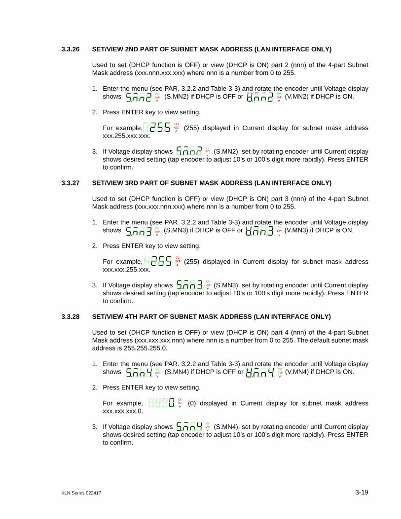
KLN Series 022417 3-19
3.3.26 SET/VIEW 2ND PART OF SUBNET MASK ADDRESS (LAN INTERFACE ONLY)
Used to set (DHCP function is OFF) or view (DHCP is ON) part 2 (nnn) of the 4-part SubnetMask address (xxx.nnn.xxx.xxx) where nnn is a number from 0 to 255.
1. Enter the menu (see PAR. 3.2.2 and Table 3-3) and rotate the encoder until Voltage displayshows (S.MN2) if DHCP is OFF or (V.MN2) if DHCP is ON.
2. Press ENTER key to view setting.
For example, (255) displayed in Current display for subnet mask addressxxx.255.xxx.xxx.
3. If Voltage display shows (S.MN2), set by rotating encoder until Current displayshows desired setting (tap encoder to adjust 10’s or 100’s digit more rapidly). Press ENTERto confirm.
3.3.27 SET/VIEW 3RD PART OF SUBNET MASK ADDRESS (LAN INTERFACE ONLY)
Used to set (DHCP function is OFF) or view (DHCP is ON) part 3 (nnn) of the 4-part SubnetMask address (xxx.xxx.nnn.xxx) where nnn is a number from 0 to 255.
1. Enter the menu (see PAR. 3.2.2 and Table 3-3) and rotate the encoder until Voltage displayshows (S.MN3) if DHCP is OFF or (V.MN3) if DHCP is ON.
2. Press ENTER key to view setting.
For example, (255) displayed in Current display for subnet mask addressxxx.xxx.255.xxx.
3. If Voltage display shows (S.MN3), set by rotating encoder until Current displayshows desired setting (tap encoder to adjust 10’s or 100’s digit more rapidly). Press ENTERto confirm.
3.3.28 SET/VIEW 4TH PART OF SUBNET MASK ADDRESS (LAN INTERFACE ONLY)
Used to set (DHCP function is OFF) or view (DHCP is ON) part 4 (nnn) of the 4-part SubnetMask address (xxx.xxx.xxx.nnn) where nnn is a number from 0 to 255. The default subnet maskaddress is 255.255.255.0.
1. Enter the menu (see PAR. 3.2.2 and Table 3-3) and rotate the encoder until Voltage displayshows (S.MN4) if DHCP is OFF or (V.MN4) if DHCP is ON.
2. Press ENTER key to view setting.
For example, (0) displayed in Current display for subnet mask addressxxx.xxx.xxx.0.
3. If Voltage display shows (S.MN4), set by rotating encoder until Current displayshows desired setting (tap encoder to adjust 10’s or 100’s digit more rapidly). Press ENTERto confirm.
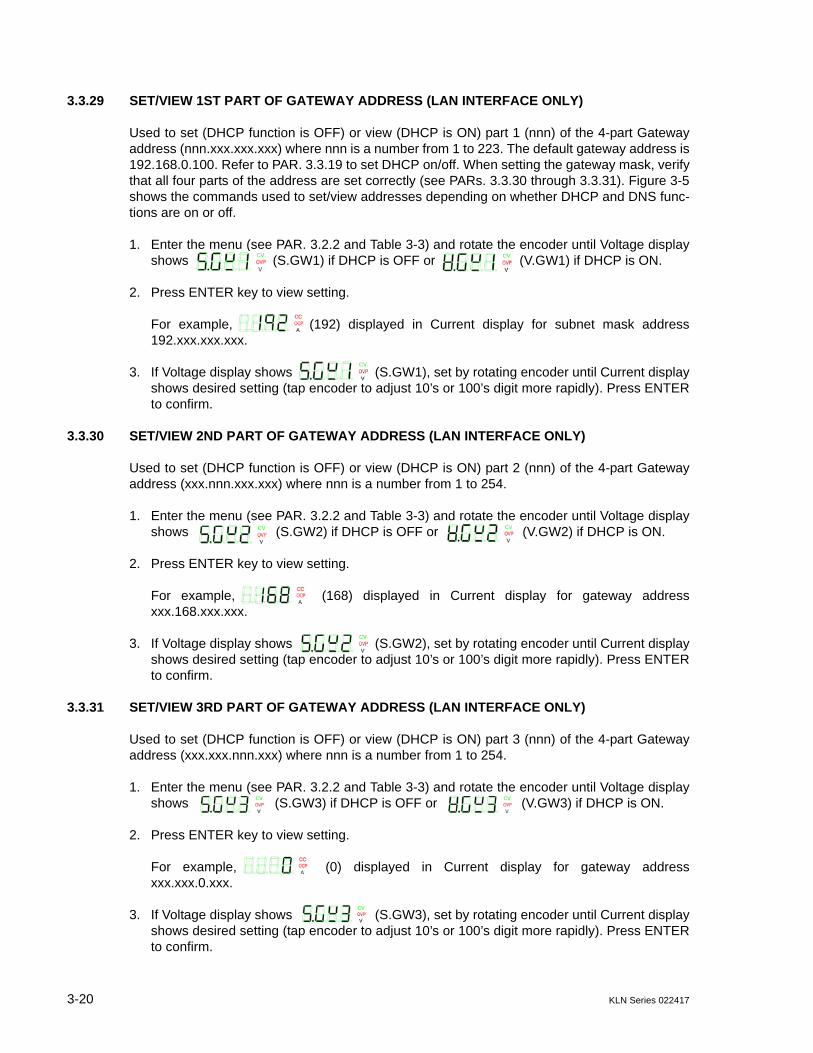
3-20 KLN Series 022417
3.3.29 SET/VIEW 1ST PART OF GATEWAY ADDRESS (LAN INTERFACE ONLY)
Used to set (DHCP function is OFF) or view (DHCP is ON) part 1 (nnn) of the 4-part Gatewayaddress (nnn.xxx.xxx.xxx) where nnn is a number from 1 to 223. The default gateway address is192.168.0.100. Refer to PAR. 3.3.19 to set DHCP on/off. When setting the gateway mask, verifythat all four parts of the address are set correctly (see PARs. 3.3.30 through 3.3.31). Figure 3-5shows the commands used to set/view addresses depending on whether DHCP and DNS func-tions are on or off.
1. Enter the menu (see PAR. 3.2.2 and Table 3-3) and rotate the encoder until Voltage displayshows (S.GW1) if DHCP is OFF or (V.GW1) if DHCP is ON.
2. Press ENTER key to view setting.
For example, (192) displayed in Current display for subnet mask address192.xxx.xxx.xxx.
3. If Voltage display shows (S.GW1), set by rotating encoder until Current displayshows desired setting (tap encoder to adjust 10’s or 100’s digit more rapidly). Press ENTERto confirm.
3.3.30 SET/VIEW 2ND PART OF GATEWAY ADDRESS (LAN INTERFACE ONLY)
Used to set (DHCP function is OFF) or view (DHCP is ON) part 2 (nnn) of the 4-part Gatewayaddress (xxx.nnn.xxx.xxx) where nnn is a number from 1 to 254.
1. Enter the menu (see PAR. 3.2.2 and Table 3-3) and rotate the encoder until Voltage displayshows (S.GW2) if DHCP is OFF or (V.GW2) if DHCP is ON.
2. Press ENTER key to view setting.
For example, (168) displayed in Current display for gateway addressxxx.168.xxx.xxx.
3. If Voltage display shows (S.GW2), set by rotating encoder until Current displayshows desired setting (tap encoder to adjust 10’s or 100’s digit more rapidly). Press ENTERto confirm.
3.3.31 SET/VIEW 3RD PART OF GATEWAY ADDRESS (LAN INTERFACE ONLY)
Used to set (DHCP function is OFF) or view (DHCP is ON) part 3 (nnn) of the 4-part Gatewayaddress (xxx.xxx.nnn.xxx) where nnn is a number from 1 to 254.
1. Enter the menu (see PAR. 3.2.2 and Table 3-3) and rotate the encoder until Voltage displayshows (S.GW3) if DHCP is OFF or (V.GW3) if DHCP is ON.
2. Press ENTER key to view setting.
For example, (0) displayed in Current display for gateway addressxxx.xxx.0.xxx.
3. If Voltage display shows (S.GW3), set by rotating encoder until Current displayshows desired setting (tap encoder to adjust 10’s or 100’s digit more rapidly). Press ENTERto confirm.

KLN Series 022417 3-21
3.3.32 SET/VIEW 4TH PART OF GATEWAY ADDRESS (LAN INTERFACE ONLY)
Used to set (DHCP function is OFF) or view (DHCP is ON) part 4 (nnn) of the 4-part Gatewayaddress (xxx.xxx.xxx.nnn) where nnn is a number from 1 to 254.
Enter the menu (see PAR. 3.2.2 and Table 3-3) and rotate the encoder until Voltage displayshows (S.GW4) if DHCP is OFF or (V.GW4) if DHCP is ON.
1. Press ENTER key to view setting.
For example, (100) displayed in Current display for gateway addressxxx.xxx.xxx.100.
2. If Voltage display shows (S.MN4), set by rotating encoder until Current displayshows desired setting (tap encoder to adjust 10’s or 100’s digit more rapidly). Press ENTERto confirm.
3.3.33 SET/VIEW 1ST PART OF DNS ADDRESS (LAN INTERFACE ONLY)
Used to set (DNS function is OFF) or view (DNS is ON) part 1 (nnn) of the 4-part DNS address(nnn.xxx.xxx.xxx) where nnn is a number from 1 to 223. The default DNS address is 8.8.8.8.Refer to PAR. 3.3.20 to set DNS on/off. When setting the DNS address, verify that all four partsof the address are set correctly (see PARs. 3.3.30 through 3.3.31). Figure 3-5 shows the com-mands used to set/view addresses depending on whether DHCP and DNS functions are on oroff.
1. Enter the menu (see PAR. 3.2.2 and Table 3-3) and rotate the encoder until Voltage displayshows (S.DN1) if DNS is OFF or (V.DN1) if DNS is ON.
2. Press ENTER key to view setting.
For example, (8) displayed in Current display for DNS address 8.xxx.xxx.xxx.
3. If Voltage display shows (S.GW1), set by rotating encoder until Current displayshows desired setting (tap encoder to adjust 10’s or 100’s digit more rapidly). Press ENTERto confirm.
3.3.34 SET/VIEW 2ND PART OF DNS ADDRESS (LAN INTERFACE ONLY)
Used to set (DNS function is OFF) or view (DNS is ON) part 2 (nnn) of the 4-part DNS address(xxx.nnn.xxx.xxx) where nnn is a number from 1 to 254.
1. Enter the menu (see PAR. 3.2.2 and Table 3-3) and rotate the encoder until Voltage displayshows (S.DN2) if DNS is OFF or (V.DN2) if DNS is ON.
2. Press ENTER key to view setting.
For example, (8) displayed in Current display for DNS address xxx.8.xxx.xxx.
3. If Voltage display shows (S.DN2), set by rotating encoder until Current displayshows desired setting (tap encoder to adjust 10’s or 100’s digit more rapidly). Press ENTERto confirm.
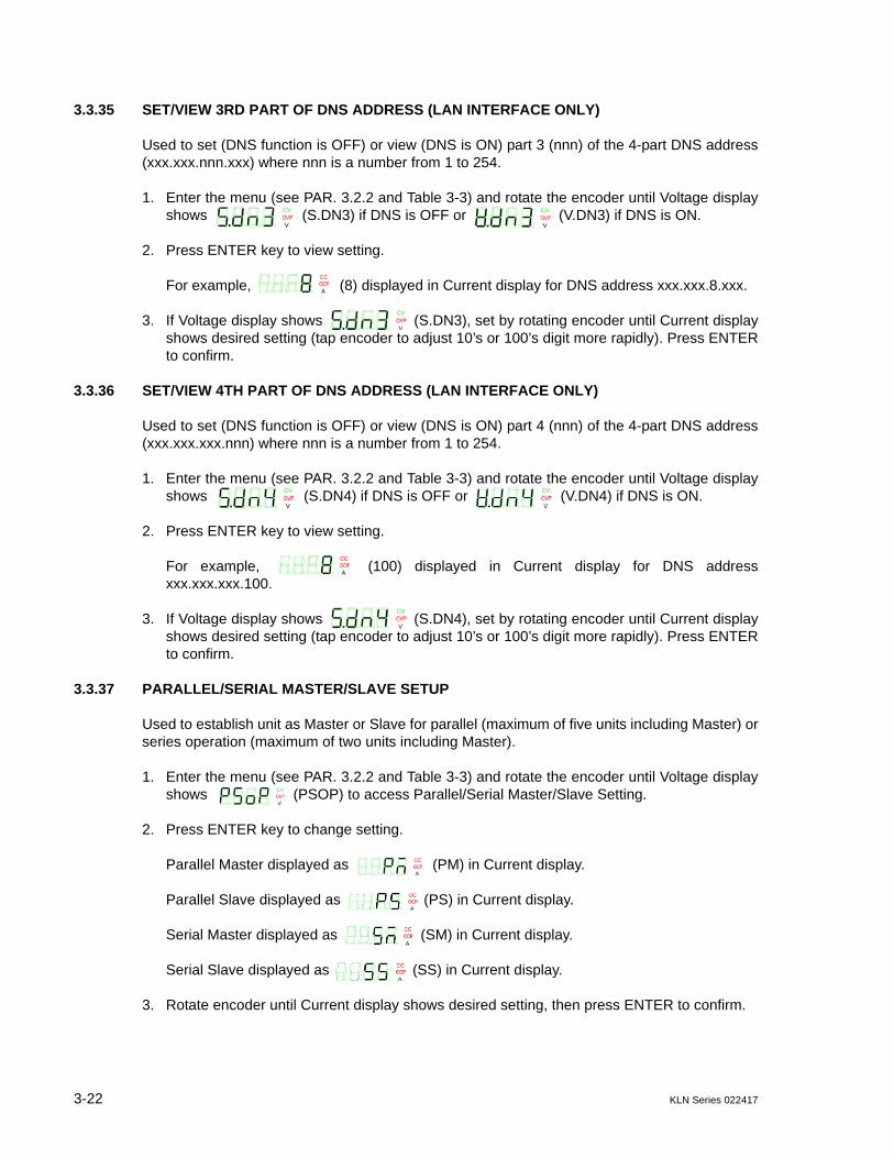
3-22 KLN Series 022417
3.3.35 SET/VIEW 3RD PART OF DNS ADDRESS (LAN INTERFACE ONLY)
Used to set (DNS function is OFF) or view (DNS is ON) part 3 (nnn) of the 4-part DNS address(xxx.xxx.nnn.xxx) where nnn is a number from 1 to 254.
1. Enter the menu (see PAR. 3.2.2 and Table 3-3) and rotate the encoder until Voltage displayshows (S.DN3) if DNS is OFF or (V.DN3) if DNS is ON.
2. Press ENTER key to view setting.
For example, (8) displayed in Current display for DNS address xxx.xxx.8.xxx.
3. If Voltage display shows (S.DN3), set by rotating encoder until Current displayshows desired setting (tap encoder to adjust 10’s or 100’s digit more rapidly). Press ENTERto confirm.
3.3.36 SET/VIEW 4TH PART OF DNS ADDRESS (LAN INTERFACE ONLY)
Used to set (DNS function is OFF) or view (DNS is ON) part 4 (nnn) of the 4-part DNS address(xxx.xxx.xxx.nnn) where nnn is a number from 1 to 254.
1. Enter the menu (see PAR. 3.2.2 and Table 3-3) and rotate the encoder until Voltage displayshows (S.DN4) if DNS is OFF or (V.DN4) if DNS is ON.
2. Press ENTER key to view setting.
For example, (100) displayed in Current display for DNS addressxxx.xxx.xxx.100.
3. If Voltage display shows (S.DN4), set by rotating encoder until Current displayshows desired setting (tap encoder to adjust 10’s or 100’s digit more rapidly). Press ENTERto confirm.
3.3.37 PARALLEL/SERIAL MASTER/SLAVE SETUP
Used to establish unit as Master or Slave for parallel (maximum of five units including Master) orseries operation (maximum of two units including Master).
1. Enter the menu (see PAR. 3.2.2 and Table 3-3) and rotate the encoder until Voltage displayshows (PSOP) to access Parallel/Serial Master/Slave Setting.
2. Press ENTER key to change setting.
Parallel Master displayed as (PM) in Current display.
Parallel Slave displayed as (PS) in Current display.
Serial Master displayed as (SM) in Current display.
Serial Slave displayed as (SS) in Current display.
3. Rotate encoder until Current display shows desired setting, then press ENTER to confirm.

KLN Series 022417 3-23
3.3.38 EXTERNAL CONTROL OF OUTPUT ON/OFF
This function enables or disables external control of output on/off using the Programming Con-trol port.
1. Enter the menu (see PAR. 3.2.2 and Table 3-3) and rotate the encoder until Voltage displayshows (EO.C) to access EXTERNAL OUTPUT ON/OFF CONTROL function.
OFF (default) displayed as (OFF) in Current display.
ON displayed as (ON) in Current display.
2. Press ENTER key to change setting. Rotate encoder until Current display shows desiredsetting, then press ENTER to confirm.
3.3.39 ENABLE VOLTAGE CONTROL VIA PROGRAMMING CONTROL PORT
Allows voltage control either from the front panel (LOCAL) or from the analog signal via the Pro-gramming Control port (EXTERNAL)
1. Enter the menu (see PAR. 3.2.2 and Table 3-3) and rotate the encoder until Voltage displayshows (CV.M) to access CONSTANT VOLTAGE MODE CONTROL setting.
2. Press ENTER key to view setting.
LOCAL (front panel) mode displayed as (LOC) in Current display.
EXTERNAL (Programming Control port) mode displayed as (EXT) in Currentdisplay.
3. Rotate encoder until Current display shows desired setting, then press ENTER to confirm.
3.3.40 ENABLE CURRENT CONTROL VIA PROGRAMMING CONTROL PORT
Allows current control either from the front panel (LOCAL) or from the analog signal via the Pro-gramming Control port (EXTERNAL)
1. Enter the menu (see PAR. 3.2.2 and Table 3-3) and rotate the encoder until Voltage displayshows (CC.M) to access CONSTANT CURRENT MODE CONTROL setting.
2. Press ENTER key to view setting.
LOCAL (front panel) mode displayed as (LOC) in Current display.
EXTERNAL (Programming Control port) mode displayed as (EXT) in Currentdisplay.
3. Rotate encoder until Current display shows desired setting, then press ENTER to confirm.

3-24 KLN Series 022417
3.3.41 CALIBRATION ACCESS
Allows access to calibration mode which is password protected.
1. Enter the menu (see PAR. 3.2.2 and Table 3-3) and rotate the encoder until Voltage displayshows (CAL) to access CALIBRATION mode.
2. Press ENTER key to access setting (password).
3. Rotate encoder until Current display shows desired setting for blinking digit.
4. Tap encoder to go to next digit and repeat step 3 for all digits of the password, then pressENTER to confirm.
5. Refer to PAR. 4.1 to calibrate the unit.
3.3.42 VIEW SERIAL NUMBER
Allows viewing of 6-digit serial number.
1. Enter the menu (see PAR. 3.2.2 and Table 3-3) and rotate the encoder until Voltage displayshows (SN) in the two left-most characters.
2. Serial Number displayed starting with two right-most digits (10) in Voltage dis-play and four digits in Current display (0000).
3.3.43 VIEW MAIN CONTROL VERSION
Allows viewing of main control firmware version
1. Enter the menu (see PAR. 3.2.2 and Table 3-3) and rotate the encoder until Voltage displayshows (FW). to view the unit main control version.
2. Main Control Version displayed as 1.00 (typical) in Current display.
3.3.44 VIEW HARDWARE VERSION
Allows viewing of hardware version
1. Enter the menu (see PAR. 3.2.2 and Table 3-3) and rotate the encoder until Voltage displayshows (HW). to view the unit hardware version.
2. Hardware Version displayed as 1.00 (typical) in Current display.
3.3.45 VIEW 1ST PART OF MAC ADDRESS (LAN INTERFACE ONLY)
Used to view first two hex numbers (aa.bb) of the 6-character MAC address (aa.bb.cc.dd.ee.ff)where aa and bb are Hex numbers from 00 to FF. The default MAC address is70.60.42.00.00.00.
1. Enter the menu (see PAR. 3.2.2 and Table 3-3) and rotate the encoder until Voltage displayshows (V.MA1).
2. Press ENTER key to view setting.
For example, (70.46) displayed in Current display for MAC address70.46.42.00.00.00.
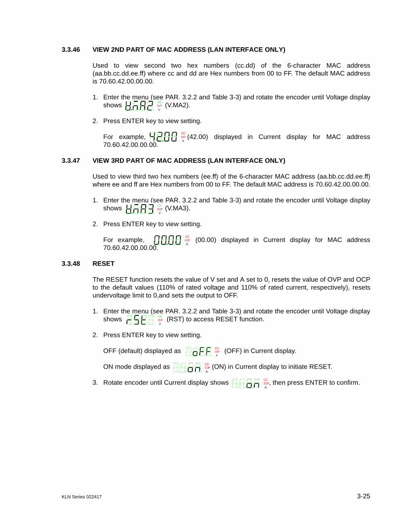
KLN Series 022417 3-25
3.3.46 VIEW 2ND PART OF MAC ADDRESS (LAN INTERFACE ONLY)
Used to view second two hex numbers (cc.dd) of the 6-character MAC address(aa.bb.cc.dd.ee.ff) where cc and dd are Hex numbers from 00 to FF. The default MAC addressis 70.60.42.00.00.00.
1. Enter the menu (see PAR. 3.2.2 and Table 3-3) and rotate the encoder until Voltage displayshows (V.MA2).
2. Press ENTER key to view setting.
For example, (42.00) displayed in Current display for MAC address70.60.42.00.00.00.
3.3.47 VIEW 3RD PART OF MAC ADDRESS (LAN INTERFACE ONLY)
Used to view third two hex numbers (ee.ff) of the 6-character MAC address (aa.bb.cc.dd.ee.ff)where ee and ff are Hex numbers from 00 to FF. The default MAC address is 70.60.42.00.00.00.
1. Enter the menu (see PAR. 3.2.2 and Table 3-3) and rotate the encoder until Voltage displayshows (V.MA3).
2. Press ENTER key to view setting.
For example, (00.00) displayed in Current display for MAC address70.60.42.00.00.00.
3.3.48 RESET
The RESET function resets the value of V set and A set to 0, resets the value of OVP and OCPto the default values (110% of rated voltage and 110% of rated current, respectively), resetsundervoltage limit to 0,and sets the output to OFF.
1. Enter the menu (see PAR. 3.2.2 and Table 3-3) and rotate the encoder until Voltage displayshows (RST) to access RESET function.
2. Press ENTER key to view setting.
OFF (default) displayed as (OFF) in Current display.
ON mode displayed as (ON) in Current display to initiate RESET.
3. Rotate encoder until Current display shows , then press ENTER to confirm.

3-26 KLN Series 022417
3.3.49 IP ADDRESS RESET (RST1)
The IP Address reset function resets the IP address to the default: 192.168.0.100/255.255.0.0and clears both Gateway and DNS addresses.
1. Enter the menu (see PAR. 3.2.2 and Table 3-3) and rotate the encoder until Voltage displayshows (RST1) to access RESET IP ADDRESS function.
2. Press ENTER key to view setting.
OFF (default) displayed as (oFF) in Current display.
ON mode displayed as (on) in Current display to initiate RESET IP ADDRESS.
3. Rotate encoder until Current display shows , then press ENTER to confirm.
3.3.50 VIEWING ERROR CODES.
When the red (alarm) LED on the front panel is lit, use the ERR function of the menu to readthe error.
1. Enter the menu (see PAR. 3.2.2 and Table 3-3) and rotate the encoder until Voltage displayshows (ERR) to access Error Codes.
2. If an error was detected, a two or three digit number is shown in the Current display. Refer toTable B-2 for a complete list of error codes. If no error, code displayed in Current display is
(0, no error).
3. Press ENTER key to erase code in Current display and read the next error code. When Cur-rent display reads 0, all error codes have been read.
3.4 SERIES/PARALLEL OPERATION
The following paragraphs describe operation of multiple units connected in series or parallel
3.4.1 SERIES OPERATION
• The front panel voltage displays of the Master and Slave each show 1/2 of the total outputvoltage of the series combination. The front panel current display of the Master shows thecurrent for the series combination
• The voltage monitoring function at pin 20 (V MON) of the Control Programming port is func-tional for both Master and Slave, 0 - 10V corresponding to 0 to full scale voltage of the indi-vidual units. Voltage monitor for the series combination is the sum of the output of pin 20 ofthe Master plus pin 20 of the Slave.
• Output ON/OFF is controlled by the Master.
• The current monitoring function at pin 22 (A MON) of the Control Programming port is func-tional for both Master and Slave, 0 - 10V corresponding to 0 to full scale current of the indi-vidual units.

KLN Series 022417 3-27
• The alarm status function at pin 9 (ALARM) of the Control Programming port is functional forboth Master and Slave. If the Master alarm status is active, the Master and Slave will beshut down. If the Slave alarm status is active, only the Slave will be shut down.
• When using remote control, only the Master can be operated and controlled by remote com-mands.
To operate units connected in series, proceed as follows:
1. Verify that the units are connected as shown in Figure 2-18 (A, with local compensation or Bwith remote compensation)
2. Verify that Programming Control Port connections are as shown in either Figure 2-18 (usingthe optional Series Connector Board shown in Figure 2-19), or Figure 2-20 (direct connec-tions).
3. Turn on power to Master unit first and then Slave unit.
4. Set PSOP (Parallel/Series operation) function in the menu to SM (Series Master) for theMaster unit and to SS (Series Slave) for the Slave unit (see PAR. 3.3.37). After settingPSOP, output ON/OFF of the series combination is controlled by the Master.
CAUTION: TO ENSURE THE PROTECTION FUNCTIONS WORK PROPERLY, SETOVP/OCP VALUES HIGHER FOR THE SLAVE UNIT.
5. Set OVP and OVC of the Slave to a higher value than that for the Master to ensure thatovervoltage and overcurrent protection work properly.
6. When powering off a series combination, first turn off the Slave, then the Master.
3.4.2 DISCONTINUING SERIES OPERATION
To allow units connected in series to function independently, proceed as follows:
1. Turn off power to Slave, then Master.
2. Disconnect all series connections shown in Figure 2-18.
3. If applicable, disconnect Programming Control Port connections shown in Figure 2-20.
4. After turning on each unit, set PSOP (Parallel/Series operation) to PM (Parallel Master) inthe Menu (see PAR. 3.3.37).

3-28 KLN Series 022417
3.4.3 PARALLEL OPERATION
• The front panel current displays of the Master and Slave(s) each show the output current ofthe individual units. The front panel voltage display of the Master shows the output voltagefor the parallel combination.
• Front panel keys of slave(s) are disabled, except that SHIFT and ENTER keys still allowaccess to the MENU functions (see PAR. 3.2.2) and SHIFT V (OVP) still allows OVP of theslave to be modified (see PAR. 3.3.2).
• The voltage monitoring function at pin 20 (V MON) of the Control Programming port is func-tional for the Master and all Slaves, 0 - 10V corresponding to 0 to full scale voltage of eachindividual unit.
• The current monitoring function at pin 22 (A MON) of the Control Programming port is func-tional for Master and all Slaves, 0 - 10V corresponding to 0 to full scale current of the indi-vidual units. Current monitor for the parallel combination is the sum of the output of pin 22 ofthe Master, plus pin 22 of all Slaves.
• The alarm status function at pin 9 (ALARM) of the Control Programming port is functional forMaster and all Slaves. If the Master alarm status is active, the Master and all Slaves will beshut down. If a Slave alarm status is active, only that Slave will be shut down.
• Remote sensing for Slave units is disabled when operating in parallel configurations.
• When using remote digital control, only the MASTER can be operated and controlled byremote commands.
To operate units connected in parallel, proceed as follows:
1. Verify that the units are connected as shown in either Figure 2-21A (with local compensa-tion) or Figure 2-21B (with remote compensation).
2. Verify that Programming Control Port connections are as shown in either Figure 2-21 (usingthe optional Parallel Connector Board shown in Figure 2-22), or Figure 2-23 (direct connec-tions).
3. Turn on power to Master unit first, then Slave units.
4. Set menu function for Ramp Down Time of both Master and Slave to 0 (see PAR. 3.3.11).
5. Set PSOP (Parallel/Series operation) function in the menu to PM (Parallel Master) for theMaster unit and to PS (Parallel Slave) for the Slave unit (see PAR. 3.3.37). After settingPSOP, output ON/OFF of the series combination is controlled by the Master.
6. Set OVP and OVC of the Slave(s) to a higher value than that for the Master to ensure thatovervoltage and overcurrent protection work properly.
7. When powering off a parallel combination, first turn off the Slave(s), then the Master.

KLN Series 022417 3-29
3.4.4 DISCONTINUING PARALLEL OPERATION
To allow units connected in parallel to function independently, proceed as follows:
1. Turn off power to Slaves, then Master.
2. Disconnect all parallel connections shown in Figure 2-21.
3. If applicable, disconnect Programming Control Port connections shown in Figure 2-23.
4. After turning on each unit, set PSOP (Parallel/Series operation) to PM (Parallel Master) inthe Menu (see PAR. 3.3.37).
3.5 ANALOG REMOTE MODE PROGRAMMING
The KLN can be programmed remotely using analog signals applied to the remote Program-ming Control port at the rear panel (see Figure 2-1 and Table 2-4). Analog remote programmingallows the user to 1) control output on/off (PAR. 3.5.1), 2) initiate emergency shutdown of theoutput (PAR. 3.5.2), 3) control output voltage (PAR. 3.5.3) or current (PAR. 3.5.4) and 4) monitorpower supply status (PAR. 3.5.6).
3.5.1 REMOTE OUTPUT ON/OFF
The output can be set on or off using the Programming Control port pins 21 and 25 (non-iso-lated). When the pins are shorted the output is on, when they are open the out is off. This can beaccomplished using either an optocoupler or relay. (See Figure 3-7). This feature must first beenabled from the front panel by setting external control of output on/off to ON (see PAR. 3.3.38).Use 5V supply from pins 13 and 14 (isolated) to power optocoupler or relay.
3.5.2 REMOTE EMERGENCY SHUTDOWN
Remote emergency shutdown of the output can be accomplished using Programming Controlport pins 23 and 25 and either an optocoupler or relay. (See Figure 3-6). When the pins areopen, operation is normal. When they are shorted, the output is immediately set to off, the red
(alarm) LED goes on, the unit beeps and error 77 is recorded. This happens regardless ofthe status of output on/off at pin 10 and whether external control of output on/off (see PAR.3.3.38) is enabled or disabled.
FIGURE 3-6. REMOTE CONTROL USING PROGRAMMING CONTROL PORT AND OPTOCOUPLER OR RELAY
EMERGENCY SHUTDOWNPINS 23 AND 25
NOTES:1. Control can be either by optocoupler or
relay.2. Recommended that contacts be posi-
tioned as close to pins as possible.
CAUTION:Observe proper polarity.!
OUTPUT ON/OFFPINS 21 AND 25
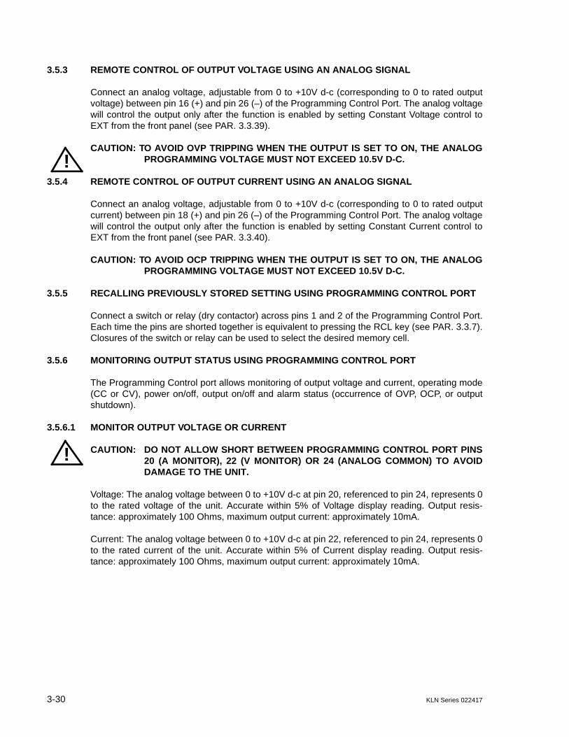
3-30 KLN Series 022417
3.5.3 REMOTE CONTROL OF OUTPUT VOLTAGE USING AN ANALOG SIGNAL
Connect an analog voltage, adjustable from 0 to +10V d-c (corresponding to 0 to rated outputvoltage) between pin 16 (+) and pin 26 (–) of the Programming Control Port. The analog voltagewill control the output only after the function is enabled by setting Constant Voltage control toEXT from the front panel (see PAR. 3.3.39).
CAUTION: TO AVOID OVP TRIPPING WHEN THE OUTPUT IS SET TO ON, THE ANALOGPROGRAMMING VOLTAGE MUST NOT EXCEED 10.5V D-C.
3.5.4 REMOTE CONTROL OF OUTPUT CURRENT USING AN ANALOG SIGNAL
Connect an analog voltage, adjustable from 0 to +10V d-c (corresponding to 0 to rated outputcurrent) between pin 18 (+) and pin 26 (–) of the Programming Control Port. The analog voltagewill control the output only after the function is enabled by setting Constant Current control toEXT from the front panel (see PAR. 3.3.40).
CAUTION: TO AVOID OCP TRIPPING WHEN THE OUTPUT IS SET TO ON, THE ANALOGPROGRAMMING VOLTAGE MUST NOT EXCEED 10.5V D-C.
3.5.5 RECALLING PREVIOUSLY STORED SETTING USING PROGRAMMING CONTROL PORT
Connect a switch or relay (dry contactor) across pins 1 and 2 of the Programming Control Port.Each time the pins are shorted together is equivalent to pressing the RCL key (see PAR. 3.3.7).Closures of the switch or relay can be used to select the desired memory cell.
3.5.6 MONITORING OUTPUT STATUS USING PROGRAMMING CONTROL PORT
The Programming Control port allows monitoring of output voltage and current, operating mode(CC or CV), power on/off, output on/off and alarm status (occurrence of OVP, OCP, or outputshutdown).
3.5.6.1 MONITOR OUTPUT VOLTAGE OR CURRENT
CAUTION: DO NOT ALLOW SHORT BETWEEN PROGRAMMING CONTROL PORT PINS20 (A MONITOR), 22 (V MONITOR) OR 24 (ANALOG COMMON) TO AVOIDDAMAGE TO THE UNIT.
Voltage: The analog voltage between 0 to +10V d-c at pin 20, referenced to pin 24, represents 0to the rated voltage of the unit. Accurate within 5% of Voltage display reading. Output resis-tance: approximately 100 Ohms, maximum output current: approximately 10mA.
Current: The analog voltage between 0 to +10V d-c at pin 22, referenced to pin 24, represents 0to the rated current of the unit. Accurate within 5% of Current display reading. Output resis-tance: approximately 100 Ohms, maximum output current: approximately 10mA.
!
!
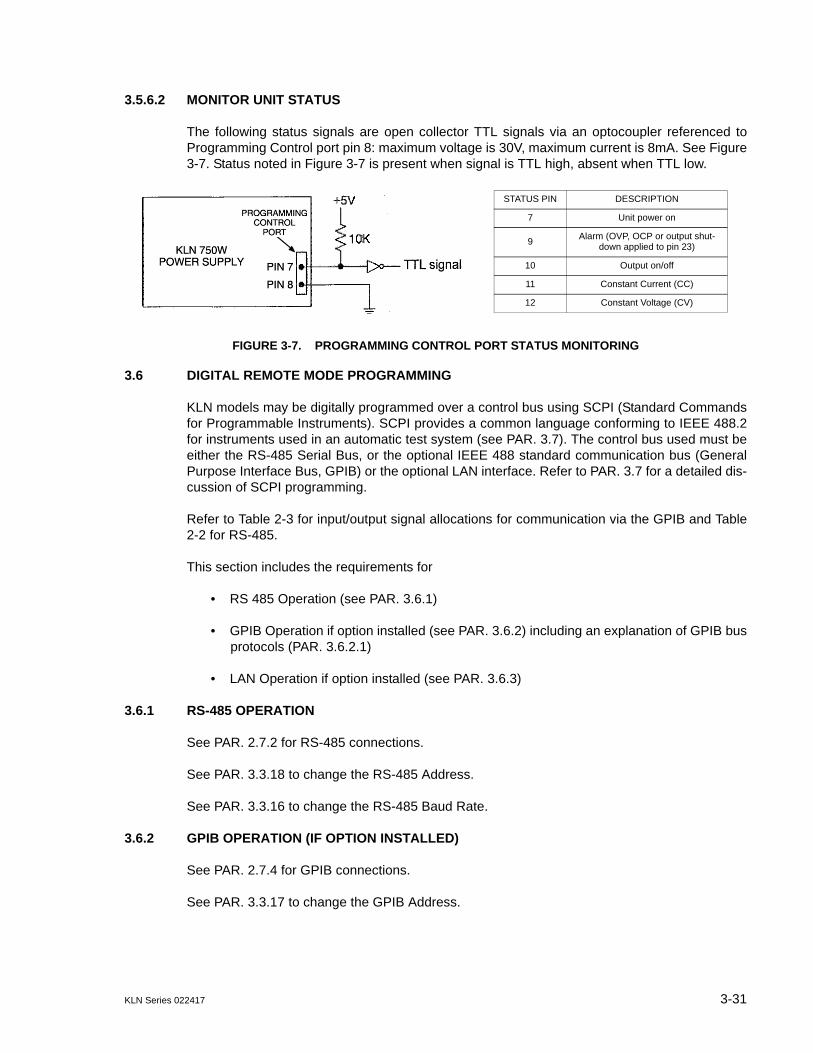
KLN Series 022417 3-31
3.5.6.2 MONITOR UNIT STATUS
The following status signals are open collector TTL signals via an optocoupler referenced toProgramming Control port pin 8: maximum voltage is 30V, maximum current is 8mA. See Figure3-7. Status noted in Figure 3-7 is present when signal is TTL high, absent when TTL low.
FIGURE 3-7. PROGRAMMING CONTROL PORT STATUS MONITORING
3.6 DIGITAL REMOTE MODE PROGRAMMING
KLN models may be digitally programmed over a control bus using SCPI (Standard Commandsfor Programmable Instruments). SCPI provides a common language conforming to IEEE 488.2for instruments used in an automatic test system (see PAR. 3.7). The control bus used must beeither the RS-485 Serial Bus, or the optional IEEE 488 standard communication bus (GeneralPurpose Interface Bus, GPIB) or the optional LAN interface. Refer to PAR. 3.7 for a detailed dis-cussion of SCPI programming.
Refer to Table 2-3 for input/output signal allocations for communication via the GPIB and Table2-2 for RS-485.
This section includes the requirements for
• RS 485 Operation (see PAR. 3.6.1)
• GPIB Operation if option installed (see PAR. 3.6.2) including an explanation of GPIB busprotocols (PAR. 3.6.2.1)
• LAN Operation if option installed (see PAR. 3.6.3)
3.6.1 RS-485 OPERATION
See PAR. 2.7.2 for RS-485 connections.
See PAR. 3.3.18 to change the RS-485 Address.
See PAR. 3.3.16 to change the RS-485 Baud Rate.
3.6.2 GPIB OPERATION (IF OPTION INSTALLED)
See PAR. 2.7.4 for GPIB connections.
See PAR. 3.3.17 to change the GPIB Address.
STATUS PIN DESCRIPTION
7 Unit power on
9Alarm (OVP, OCP or output shut-
down applied to pin 23)
10 Output on/off
11 Constant Current (CC)
12 Constant Voltage (CV)
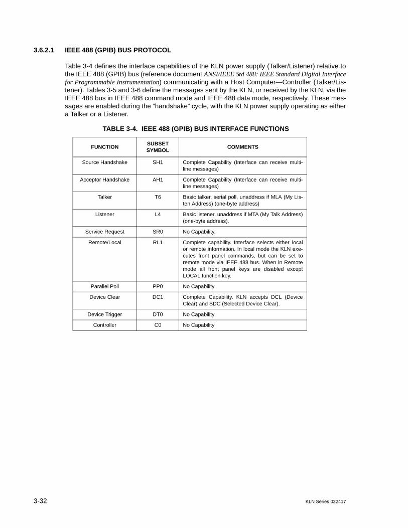
3-32 KLN Series 022417
3.6.2.1 IEEE 488 (GPIB) BUS PROTOCOL
Table 3-4 defines the interface capabilities of the KLN power supply (Talker/Listener) relative tothe IEEE 488 (GPIB) bus (reference document ANSI/IEEE Std 488: IEEE Standard Digital Interfacefor Programmable Instrumentation) communicating with a Host Computer—Controller (Talker/Lis-tener). Tables 3-5 and 3-6 define the messages sent by the KLN, or received by the KLN, via theIEEE 488 bus in IEEE 488 command mode and IEEE 488 data mode, respectively. These mes-sages are enabled during the “handshake” cycle, with the KLN power supply operating as eithera Talker or a Listener.
TABLE 3-4. IEEE 488 (GPIB) BUS INTERFACE FUNCTIONS
FUNCTIONSUBSET SYMBOL
COMMENTS
Source Handshake SH1 Complete Capability (Interface can receive multi-line messages)
Acceptor Handshake AH1 Complete Capability (Interface can receive multi-line messages)
Talker T6 Basic talker, serial poll, unaddress if MLA (My Lis-ten Address) (one-byte address)
Listener L4 Basic listener, unaddress if MTA (My Talk Address)(one-byte address).
Service Request SR0 No Capability.
Remote/Local RL1 Complete capability. Interface selects either localor remote information. In local mode the KLN exe-cutes front panel commands, but can be set toremote mode via IEEE 488 bus. When in Remotemode all front panel keys are disabled exceptLOCAL function key.
Parallel Poll PP0 No Capability
Device Clear DC1 Complete Capability. KLN accepts DCL (DeviceClear) and SDC (Selected Device Clear).
Device Trigger DT0 No Capability
Controller C0 No Capability

KLN Series 022417 3-33
TABLE 3-5. IEEE 488 (GPIB) BUS COMMAND MODE MESSAGES
MNEMONICMESSAGE
DESCRIPTIONCOMMENTS
ATN Attention Received
DAC Data accepted Received or Sent
DAV Data Valid Received or Sent
DCL Device Clear Received
IFC Interface Clear Received
MLA My Listen Address Received
MTA My Talk Address Received
OTA Other Talk Address Received
RFD Ready for Data Received or Sent
SDC Selected Device Clear Received
SPD Serial Poll Disable Received
SPE Serial Poll Enable Received
SRQ Service Request Sent
UNL Unlisten Received
UNT Untalk Received
TABLE 3-6. IEEE 488 (GPIB) BUS DATA MODE MESSAGES
MNEMONIC MESSAGE DESCRIPTION COMMENTS
DAB Data Byte Received or Sent
END End Received or Sent
EOS End of String Received or Sent
RQS Request Service Sent
STB Status Byte Sent
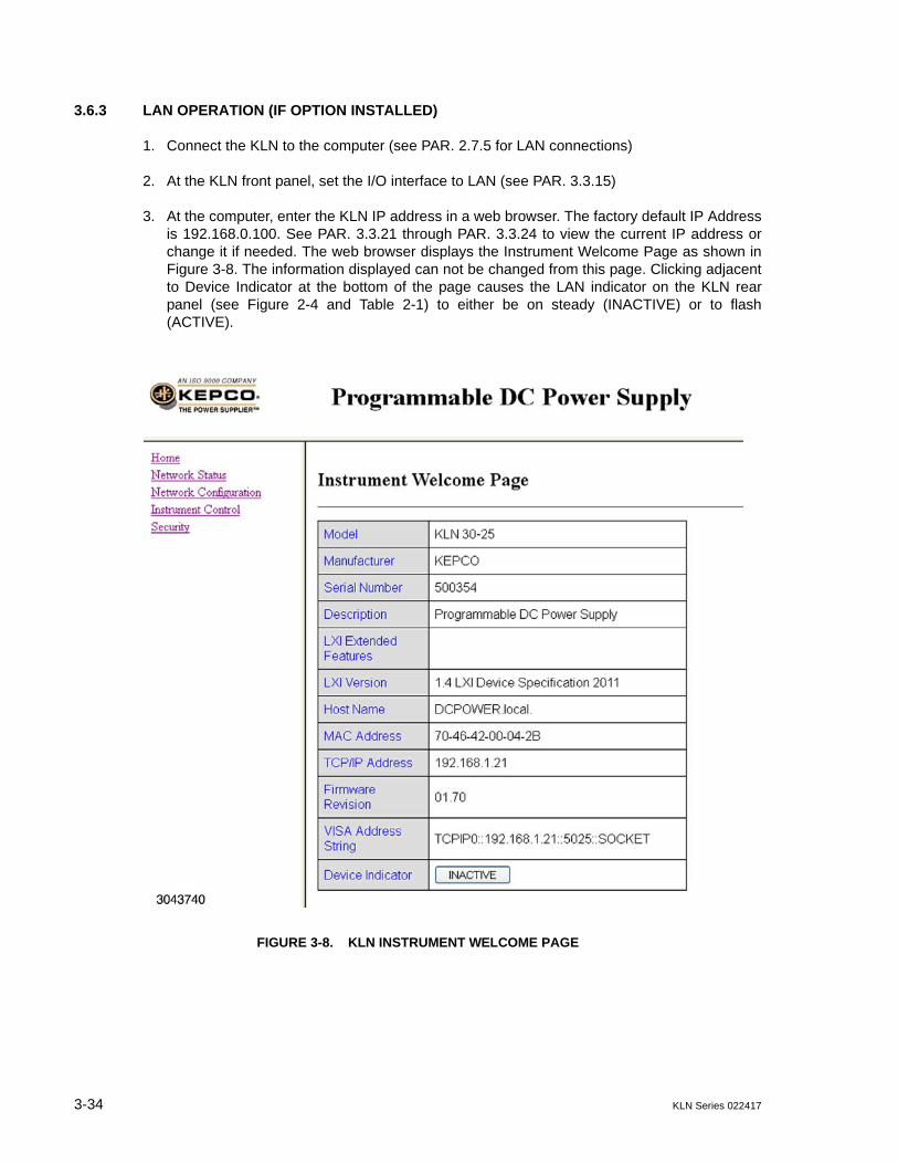
3-34 KLN Series 022417
3.6.3 LAN OPERATION (IF OPTION INSTALLED)
1. Connect the KLN to the computer (see PAR. 2.7.5 for LAN connections)
2. At the KLN front panel, set the I/O interface to LAN (see PAR. 3.3.15)
3. At the computer, enter the KLN IP address in a web browser. The factory default IP Addressis 192.168.0.100. See PAR. 3.3.21 through PAR. 3.3.24 to view the current IP address orchange it if needed. The web browser displays the Instrument Welcome Page as shown inFigure 3-8. The information displayed can not be changed from this page. Clicking adjacentto Device Indicator at the bottom of the page causes the LAN indicator on the KLN rearpanel (see Figure 2-4 and Table 2-1) to either be on steady (INACTIVE) or to flash(ACTIVE).
FIGURE 3-8. KLN INSTRUMENT WELCOME PAGE

KLN Series 022417 3-35
3.6.3.1 NETWORK STATUS
Clicking Network Status at the top left shows the Network Status Page (see Figure 3-9). Datadisplayed can not be changed from this page.
FIGURE 3-9. NETWORK STATUS PAGE
3.6.3.2 VIEWING AND/OR CHANGING IP CONFIGURATION
Clicking Network Configuration brings up the Log in screen (see Figure 3-10. Enter the pass-word (admin is the default password) and click SUBMIT to continue and view the Network Con-figuration Page (see Figure 3-11).
FIGURE 3-10. LOG IN SCREEN
3-36 KLN Series 022417
FIGURE 3-11. NETWORK CONFIGURATION PAGE
The four fields of the top section allow the user to set Host Name, Description and Domain aswell as enable or disable mDNS Discovery. Using mDNS allows the KLN to determine the IPaddress of a given host (a host name) without the direct help of a centralised DNS server. Oncechanges have been made, immediately below the top section click on Cancel to revert to theprevious settings, or Apply to apply the changes.
The lower section determines where the IP Address and DNS Server address comes from, andcan be used to manually change the Socket Port from 5025 (the default) if needed. Setting IPAddress From to DHCP-Auto allows the IP, Subnet Mask and Default Gateway addresses tobe found automatically. If IP Address From is set to Manual the user can enter the desiredaddresses, Similarly, Setting DNS Server Address From to Auto or Manual allows Preferredand Alternate DNS addresses to be found automatically or be assigned by the user. Oncechanges have been made, immediately below the lower section click on Cancel to revert to theprevious settings, or Apply to apply the changes. Clicking on LAN Configuration Initialize willrestore the IP Configuration Settings to the factory default.
KLN Series 022417 3-37
3.6.3.3 CHANGING LAN PASSWORD
When operating the KLN via the LAN for the first time, click Security at the top left of the Wel-come Page to bring up the Change Password screen (Figure 3-12). If desired, change the oldpassword from the default (admin) to one of your choosing. Ensure that New Password andConfirm Password fields are identical. If the password is lost, it can be reset to “admin” by exe-cuting the IP Address Reset (RST1) from the front panel (see PAR. 3.3.49). however this willalso reset other LAN settings to the default as well.
FIGURE 3-12. CHANGE PASSWORD SCREEN
3.6.3.4 INSTRUMENT CONTROL
The Instrument Control page (see Figure 3-13) contains the basic controls used to operate theKLN power supply. To view the Instrument Control page, click on Instrument Control at the topleft of the Welcome page. You may be asked to Log In with a password before access to thisscreen is granted. Voltage and current setpoints are displayed above the empty fields above theSet V and Set I buttons, respectively. The output can be enabled by the OUTPUT ON/OFF but-ton at the right. If the output is on, the ON indicator (at the lower left of the group of six indica-tors) is on, and the voltage and current displayed appear at the output. To programvoltage/current, enter the setpoint value in the field above the corresponding SET button, thenclick the SET button to apply the change. The CC, CV, OCP, OVP ON and Alarm indicators cor-respond to the front panel indicators (see Figure 3-1 (750W), 3-2 (1500W), or 3-3 (3000W), andTable 3-1. The RESET button corresponds to the front panel RESET button.
FIGURE 3-13. INSTRUMENT CONTROL PAGE

3-38 KLN Series 022417
3.6.3.5 OPERATION VIA HYPERTERMINAL.
HyperTerminal can be used to operate the unit remotely via the LAN connection or it can beused to verify the LAN connection is operating properly.
1. From the computer, launch HyperTerminal (e.g., Start - Programs - Accessories - Communi-cations - HyperTerminal) and key in the name of the connection, e.g., KLN 20-38E.
FIGURE 3-14. OPEN HYPERTERMINAL CONNECTION
2. At the “Properties” dialog box, open the “Connect using“ drop-down menu and select“TCP/IP(Winsock)” then key in the Host address (see PAR. 3.3.21 through 3.3.24) andsocket port (5025). HyperTerminal window shows screen with blinking cursor while connect-ing.
a. If a Message box opens that says “Unable to Connect to 192.168.0.100 port 5025” clickOK, then click File - Properties at the top menu bar of the HyperTerminal window toopen the Properties Dialog Box (Figure 3-15).
FIGURE 3-15. HYPER TERMINAL PROPERTIES
b. Click the Settings tab, then click ASCII setup (see Figure 3-16).

KLN Series 022417 3-39
FIGURE 3-16. HYPER TERMINAL ASCII SETUP
c. Check the “Send line ends with line feeds” and “Echo typed characters locally” boxes.
3. Repeat steps 1 and 2, then, from the computer via the blank HyperTerminal screen, sendsyst:rem and ENTER. The green remote LED at the KLN front panel goes on.
4. Send *idn? query to verify unit is operating properly via the LAN interface. A typicalresponse for a successful LAN connection is:
KEPCO,KLN 20-38E,500354,01.605. Send SCPI commands (see PAR. 3.7 and Appendix A and B) to drive the unit.
3.7 SCPI PROGRAMMING
SCPI (Standard Commands for Programmable Instruments) is a programming language con-forming to the protocols and standards established by IEEE 488.2 (reference documentANSI/IEEE Std 488.2, IEEE Standard Codes, Formats, Protocols, and Common Commands). The KLNPower Supply supports long and short form syntax as defined in this standard. All other aspectsof this standard are specified in Appendix B of this manual. The unit ignores all incorrectly for-matted messages, emitting an audible beep for each incorrect command sequence; the reasonfor the beep is placed in the error queue.
Different programming languages (e.g., BASIC, C, PASCAL, etc.) have different ways of repre-senting data that is to be put on the IEEE 488 bus. It is up to the programmer to determine howto output the character sequence required for the programming language used. See Table 3-7for VISA resource strings corresponding to RS-485, GPIB (G-suffix models only) or LAN (E-suf-fix models only) interfaces.
TABLE 3-7. VISA RESOURCE STRING CORRESPONDING TO INTERFACE
INTERFACE VISA RESOURCE STRING COMMENT
GPIB GPIB::xx::INSTR The GPIB address replaces xx. Address information not included with command sequences. See PAR. 3.3.17 to set GPIB address.
RS-485 ASRLy::INSTR The com port number replaces y. RS 485 address must be included in each command sequence. See PAR. 3.3.18 to set RS-485 address.
LAN TCIP::192.168.0.100::5025::SOCKET 5025 is the default socket. See PAR 3.6.3.2 to verify or change the socket port. Address information not included with command sequences.

3-40 KLN Series 022417
3.7.1 SCPI MESSAGES
There are two kinds of SCPI messages: program messages from controller to power supply,and response messages from the power supply to the controller. Program messages consist ofone or more properly formatted commands/queries and instruct the power supply to perform anaction; the controller may send a program message at any time. Response messages consist offormatted data; the data can contain information regarding operating parameters, power supplystate, status, or error conditions.
3.7.2 COMMON COMMANDS/QUERIES
Common commands and queries are defined by the IEEE 488.2 standard to perform overallpower supply functions (such as identification, status, or synchronization) unrelated to specificpower supply operation (such as setting voltage/current). Common commands and queries arepreceded by an asterisk (*) and are defined and explained in Appendix A.
3.7.3 SCPI SUBSYSTEM COMMAND/QUERY STRUCTURE
Subsystem commands/queries are related to specific power supply functions (such as settingoutput voltage, current, etc.) Figure 3-17 is a tree diagram illustrating the structure of SCPI sub-system commands used in the KLN Power Supply with the root at the left side, and specificcommands forming the branches. The following paragraphs introduce the subsystems; subsys-tem commands are defined and explained in Appendix B.
3.7.3.1 CALIBRATE SUBSYSTEM
This subsystem is used to calibrate the unit, however these commands and queries are notaccessible to the user.
3.7.3.2 DISPLAY SUBSYSTEM
This subsystem is used to set and ascertain the brightness on the front panel Voltage and Cur-rent displays.
3.7.3.3 FETCH SUBSYSTEM
This subsystem is used to measure and return both voltage and current measurements.
3.7.3.4 OUTPUT SUBSYSTEM
This subsystem is used to control whether the output is on or off, and whether the power supplypowers up with the output set to the reset state or to the last settings in effect when the unit waspowered off.
3.7.3.5 SOURCE SUBSYSTEM
This subsystem is used to program the output voltage and current of the power supply, associ-ated protection levels and limits and output ramp up and down times. This subsystem is alsoused to control the memory locations used to store power supply settings for later recall.
3.7.3.6 SYSTEM SUBSYSTEM
This subsystem is used to control the audible beep upon key presses, enabling/disabling thefront panel keys and reading of error codes and SCPI version.

KLN Series 022417 3-41/(3-42 Blank)
3.7.4 UNDERSTANDING THE COMMAND STRUCTURE
Understanding the command structure requires an understanding of the subsystem commandtree illustrated in Figure 3-17. The “root” is located at the top left corner of the diagram. Theparser goes to the root if:
• a message terminator is recognized by the parser• a root specifier is recognized by the parser
Starting at the root, there are various branches or paths corresponding to the subsystems. Theroot keywords for the KLN Power Supply are :CALibrate, :DISPlay, :FETCh, :OUTPut, :SOURceand :SYSTem.
FIGURE 3-17. TREE DIAGRAM OF SCPI COMMANDS USED WITH KLN POWER SUPPLY
CALibrate subsystemCAL
DISPlay subsystemDISP
:CONT:CONT?
FETCh subsystemFETC
:FETC?]
OUTPut subsystemOUTP
[:STAT] [:STAT]?:OUTP:OUTP?:OUTP:PON:OUTP:PON?
ROOT : (colon)
SYSTem subsystemSYSTem
:BEEP:BEEP?:COMM
:LAN:DHCP:DHCP?:GATE:GATE?:IP:IP?:IPAD:IPAD?:MAC:MAC?:RES:SMAS:SMAS?:TEL:PORT:TEL:PORT?
:ERR?:KLOC:KLOC?:LOC:REM:VERS?
SOURce: subsystemSOUR
:CURR:CURR?
:PROT:LEV:PROT:LEV?
:LIST:RTIM:RTIM?
:MEM:CLS:CURR:X:CURR:X?:LIST:X?:REC:X:REC:X?:VOLT:X:VOLT:X?
:VOLT:VOLT?
:LIM:LOW:LOW?
:PROT:LEV:PROT:LEV?


KLN Series 022417 4-1
SECTION 4 - CALIBRATION
4.1 GENERAL
This section contains the calibration instructions for the Power Supply. It is recommended thatthe user be familiar with Local Mode operation (PAR. 3.3) before calibrating the unit.
CAUTION: IT IS RECOMMENDED THAT CALIBRATION BE PERFORMED ONLY BYAUTHORIZED PERSONNEL FAMILIAR WITH ELECTRONIC TEST AND CALI-BRATION EQUIPMENT.
A full calibration consist of a voltage calibration and a current calibration. Both voltage and cur-rent calibrations consist of a full scale calibration.
Calibration of the KLN is performed locally using the front panel controls
NOTE: Calibration of a master/slave configuration requires that both units be restored tostandalone operation (see PAR. 3.4.2 or 3.4.4 for instructions) and calibrated individu-ally.
4.2 EQUIPMENT REQUIRED
The following equipment is required to calibrate the KLN Power Supply.
• Digital Voltmeter (DVM) with 6 digits resolution and at least 0.002% accuracy for d-c measurements.
NOTE: Because the voltage measured will be used as a reference for calibration, the DVMused must be accurately calibrated prior to calibrating the power supply.
• Precision Shunt Resistor (with a tolerance of 0.01%, power rating of at least 10 times larger than the maximum stress, and a temperature coefficient equal to or better than 20 ppm per degree C).
NOTE: Proper cooling of the external precision shunt resistor ensures the accuracy of the cal-ibration.
4.3 VOLTAGE CALIBRATION PROCEDURE
1. Turn off power supply and disconnect load from output terminals at the rear of unit.
2. Verify that power supply is configured for local error sensing (PAR. 2.5.7) and connect unit asshown in Figure 4-1.
3. Connect DVM to points “A” of sense terminal block at the rear of power supply as shown inFigure 4-1.

4-2 KLN Series 022417
FIGURE 4-1. CALIBRATION SETUP
4. Turn on power to the KLN power supply.
5. At KLN front panel, press SHIFT, then press V/OVP key. Use encoder to set Overvoltageprotection (see PAR. 3.3.2) to maximum (110% of rated voltage).
6. Press SHIFT, then press A/OCP key. Use encoder to set Overcurrent protection (see PAR.3.3.3) to maximum (110% of rated current).
7. Press V/OVP key and use encoder to set voltage (see PAR. 3.3.2) to rated voltage of the unitas shown on front panel display.
8. Press A/OCP key and use encoder to set current (see PAR. 3.3.3) to rated current of the unitas shown on front panel display.
9. Refer to Figure 4-1 and set switch SW1 to OFF position.
10.Press OUT key to enable the output.
11.Record voltage shown on front panel display.
12.Record voltage at +S and –S sense terminals using the DVM connected to points “A” asshown in Figure 4-1.
13.Press OUT key to disable the output.
14.Use the menu to gain access to calibration (see PAR. 3.3.41) using password 5958.
15.The Voltage display shows VOL.r and the Current display shows the Voltage Deviation Ratiosetting in effect:
Voltage Deviation Ratio = DVM reading /Front panel reading
16. Press ENTER key to access setting.
17.Calculate the new Voltage Deviation Ratio = (step 12 value)/(step 11 value).

KLN Series 022417 4-3/(4-4 Blank)
18. Enter the new Voltage Deviation ratio by rotating encoder until Current display showsdesired setting for blinking digit. Tap encoder to go to next digit and repeat for all digits, thenpress ENTER to confirm.
NOTE: If necessary to recalibrate, set Voltage Deviation Ratio to 1.000 and repeat VoltageCalibration procedure.
19.Press SHIFT and ENTER keys to exit.
20.Turn off power to the unit, disconnect DVM and proceed to Current Calibration (PAR. 4.4).
4.4 CURRENT CALIBRATION PROCEDURE
NOTE: This procedure continues from step 20 of Voltage Calibration procedure above.
1. Verify power is off. Connect DVM to points “B” across shunt resistor terminals as shown inFigure 4-1 and set switch SW1 to ON position.
2. Turn on power to the unit and press OUT key to enable the output.
3. Record current displayed on front panel.
4. Connect DVM to points “B” as shown in Figure 4-1, then measure voltage across shunt(DVM reading) and use this value to calculate output current using I (Amperes) = E/R whereE is the voltage across the shunt (Volts) and R is the value of the shunt resistor (ohms).Record calculated value.
5. Press OUT key to disable the output.
6. Use the menu to gain access to calibration (see PAR. 3.3.41) using password 5958.
7. Rotate encoder until the Voltage display shows Cur.r and the Current display shows the Cur-rent Deviation Ratio setting in effect:
Current Deviation Ratio = measured output current/front panel reading
8. Calculate the new Current Deviation Ratio = (step 4 value)/(step 3 value).
9. Press ENTER key to access setting.
10. Enter the new Current Deviation Ratio by rotating encoder until Current display showsdesired setting for blinking digit. Tap encoder to go to next digit and repeat for all digits, thenpress ENTER to confirm.
NOTE: If necessary to recalibrate, set Current Deviation Ratio to 1.000 and repeat CurrentCalibration procedure.
11.Press SHIFT and ENTER keys to exit.
12.Turn off power to the unit, disconnect DVM and disconnect shunt.

KLN Series 022417 A-1/(A-2 Blank)
APPENDIX A - SCPI COMMON COMMAND/QUERY DEFINITIONS
A.1 INTRODUCTION
This appendix defines the SCPI common commands and queries used with the KLN power supply.Common commands and queries are preceded by an asterisk (*) and are defined and explained inparagraphs A.2 through A.5, arranged in alphabetical order. Table A-1 provides a quick reference ofall SCPI common commands and queries used in the Interface Card.
A.2 *CLS — CLEAR STATUS COMMAND *CLSSyntax: *CLS
Description: Clears status data. Clears the following registers without affecting the corresponding Enable Regis-ters: Standard Event Status Register (ESR), Operation Status Event Register, Questionable StatusEvent Register, and Status Byte Register (STB). Also clears the Error Queue.
A.3 *IDN? — IDENTIFICATION QUERY *IDN?Syntax: *IDN?
Return value: Character string
Description: Identifies the instrument. This query requests identification. The power supply returns a string whichcontains the manufacturer name, the model, the serial number and the firmware level. The characterstring contains the following fields: <Manufacturer>, <Model>, <Serial Number>, <Firmware revision>where: <Manufacturer> = KEPCO, <Model> = KLN model number, <Serial Number> = SSSSSS<Firmware revision=n.m, (e.g, 1.0).
A.4 *RST — RESET COMMAND *RSTSyntax: *RST
Description: Resets power supply to the power on default state. The power supply output set to power-ondefault state.
After sending *RST, output voltage is set to 0, output current is set to 0, OVP is set to rated voltage+10% and OCP is set to rated current +10%. It is recommended that this command is always the firstcommand sent after remote digital control starts, to ensure that the output is set to zero and control ofoutput on/off is properly enabled.
A.5 *TST? — SELF TEST QUERY *TST?Syntax: *TST? Returned value: 0 or 1
Description: Power Supply test.This query causes the power supply to do a self test and provide the controllerwith pass/fail results. A 0 is returned if the unit passes the test. A 1 is returned to indicate the unit failedself test.
TABLE A-1. IEEE 488.2 COMMAND/QUERY INDEX
COMMAND PAR. COMMAND PAR.
*CLS A.2 *RST A.4
*IDN? A.3 *TST? A.5


KLN Series 022417 B-1
APPENDIX B - SCPI COMMAND/QUERY DEFINITIONS
B.1 INTRODUCTION
This appendix defines the SCPI subsystem commands and queries used with the KLN power sup-ply. Subsystem commands are defined in PAR. B.3 through B.62. Table B-1 provides a quick refer-ence of all SCPI subsystem commands and queries used in the KLN 750W.
B.2 NUMERICAL VALUES
<NR1> Refers to integer
<NRf> Refers to Floating (scientific notation: digits with decimal point and Exponent, e.g., 2.71E1 for 27.1.)
B.3 DISP:CONTrast COMMAND DISP:CONTSyntax: Short Form: DISP:CONT <NR1> Long Form: DISPlay:CONTrast <NR1>
Description: Sets the brightness of front panel Voltage and Current displays.
Argument: <NR1> is a value in the range from 0 to 5.
Example: DISPlay:CONTrast 3 sets display contrast to level 3.
TABLE B-1. SCPI SUBSYSTEM COMMAND/QUERY INDEX
COMMAND PAR. COMMAND PAR.
DISP:CONT, ? B.3, B.4 SOUR:VOLT:LIM:LOW, ? B.34, B.35
FETC? B.5 SOUR:VOLT:PROT:LEV, ? B.36, B.37
MEAS:ADDR? B.6 SOUR:VOLT:PROT:TRIP? B.38
MEAS:CURR? B.7 SYST:BEEP, ? B.39, B.40
MEAS:VOLT? B.8 SYST:COMM:LAN:DHCP, ? B.41, B.42
OUTP, ? B.9, B.10 SYST:COMM:LAN:DNS, ? B.43, B.44
OUTP:PON, ? B.11, B.12 SYST:COMM:LAN:DNS:AUTO, ? B.45, B.46
OUTP:PROT:CLE B.13 SYST:COMM:LAN:GATE, ? B.47, B.48
SOUR:CURR, ? B.14, B.15 SYST:COMM:LAN:IP, ? B.49, B.50
SOUR:CURR:PROT:LEV, ? B.16, B.17 SYST:COMM:LAN:IPAD, ? B.51, B.52
SOUR:CURR:PROT:STAT, ? B.18, B.19 SYST:COMM:LAN:MAC? B.53
SOUR:CURR:PROT:TRIP? B.20 SYST:COMM:LAN:RES B.54
SOUR:LIST:DTIM, ? B.21, B.22 SYST:COMM:LAN:SMAS, ? B.55, B.56
SOUR:LIST:RTIM, ? B.23, B.24 SYST:COMM:LAN:TEL:PORT, ? B.57, B.58
SOUR:MEM:CLS B.25 SYST:ERR? B.59
SOUR:MEM:CURR:X, ? B.26, B.27 SYST:KLOC, ? B.60, B.61
SOUR:MEM:LIST:X? B.28 SYST:LOC B.62
SOUR:MEM:REC:X B.29 SYST:REM B.63
SOUR:MEM:VOLT:X, ? B.30, B.31 SYST:VERS? B.64
SOUR:VOLT, ? B.32, B.33
NOTE: Commands listed above that are followed by “, ?“ have a related query.
B-2 KLN Series 022417
B.4 DISP:CONTrast? QUERY DISP:CONT?Syntax: Short Form: DISP:CONT? Long Form: DISPlay:CONTrast
Description: Returns the brightness level set by DISP:CONT.
Return Format: <NR1>
B.5 FETCh? QUERY FETC?Syntax: Short Form: FETC? Long Form: FETCh?
Description: Measures actual output voltage and current. The query performs a measurement and returnsthe value of DC output current in amperes and DC output voltage in volts.
Return Format: <NRf>
Example: FETC? returns 1.41000E+01, 3.00100E-00 (current is 14.1A and voltage is 3.001V).
B.6 MEASure:ADDRess? QUERY MEAS:ADDR?Syntax: Short Form: MEAS:ADDR? Long Form: MEASure:ADDRess?
Description: Returns the address of the KLN in a format compatible with active interface (either RS-485or GPIB). When output is OFF, output voltage and current are shown as:
0.00000E+00,0.00000E+00 (0V, 0A).
Return Format: <NR1>,<NRf+>,<NRf+>,<NRf+> equivalent to Address (preceded by “A” if RS 485),Output Voltage (volts), Output Current (amperes)
Example: MEAS:ADDR? when using RS 485 with KLN 30-100 operating at rated output:returns A007,3.00000E+01,1.00000E+02,(address is 7, output voltage is 30V, output current is 100A
MEAS:ADDR? when using GPIB with KLN 30-100 operating at rated output:returns 7,3.00000E+01,1.00000E+02(address is 7, output voltage is 30V, output current is 100A
B.7 MEASure:CURRent? QUERY MEAS:CURR?Syntax: Short Form: MEAS:CURR? Long Form: MEAS:CURRent?
Description: Returns 6 significant digits in floating format representing output current in amperes. Thenumber is two places more than shown on front panel Current display.
Return Format: <NRf> (Current in amperes)
Example: MEAS:CURR? returns 1.25024E+01 for output current of 12.5024A (front panel Current displayshows 12.50).
B.8 MEASure:VOLTage? QUERY MEAS:VOLT?Syntax: Short Form: MEAS:VOLT? Long Form: MEAS:VOLTage?
Description: Returns 6 significant digits in floating format representing output voltage in volts. The num-ber is two places more than shown on front panel Voltage display.
Return Format: <NRf> (Voltage in volts)
Example: MEAS:VOLT? returns 2.50057E+01 for output voltage of 25.0057V (front panel Voltage displayshows 25.00).

KLN Series 022417 B-3
B.9 OUTPut COMMAND OUTPSyntax: Short Form: OUTP { ON | OFF| 1 | 0 } Long Form: OUTPut { ON | OFF| 1 | 0 }
Description: Enables or disables the power supply output. To enable DC power supply output: <ON> or 1. To disable DC power supply output: <OFF> or 0.
Argument: <ON> or 1 to enable power supply output<OFF> or 0 to disable power supply output
Example: OUTP ON enables the DC output of the power supply.
B.10 OUTPut? QUERY OUTP?Syntax: Short Form: OUTP? Long Form: OUTPut?
Description: Indicates whether power supply output is enabled or disabled. Returns 0 if output disabled,returns 1 if output enabled.
Return Format: { 1 | 0 }
Example: OUTP? returns 1 (the DC output of the power supply is enabled).
B.11 OUTPut:PON COMMAND OUTP:PONSyntax: Short Form: OUTP:PON { OFF| LAST } Long Form: OUTPut:PON { OFF| LAST }
Description: Determines power up status of output and operation of OUTP command after power up orrecovery from mains loss. When set to OFF (recommended), the power supply will power upwith output off; output on/off can be controlled with OUTP command. When set to LAST (NOT rec-ommended), the power supply will return to the output setting (on or off) in effect when powerturned off or lost. If output was off, unit powers up with output off. If output was on, unit powers upwith output on, however OUTP command can no longer turn the output off and *RST is required toset output off.
Argument: <OFF> Programs the unit to output off upon power up or recovery from mains loss.<LAST> Programs the unit to output on/off setting in effect just before the unit was turned off.
Example: OUTP:PON OFF Programs the unit to output off state upon power up or recovery from mains lossand allows OUTP command to set output to on or off.
B.12 OUTPut:PON? QUERY OUTP:PON?Syntax: Short Form: OUTP:PON? Long Form: OUTPut:PON?
Description: Indicates power up status of output and operation of OUTP command after power up orrecovery from mains loss. Returns OFF if unit set to power up with output disabled, returnsLAST if unit set to power up with output set to setting in effect before unit was turned off
Return Format: { OFF | LAST }
Example: OUTP:PON? returns OFF (the unit will power up with output off.
B.13 OUTPut:PROTection:CLEar COMMAND OUTP:PROT:CLESyntax: Short Form: OUTP:PROT:CLE Long Form: OUTPut:PROTection:CLEar
Description: Clears the latched signals that have disabled the output. Overvoltage and overcurrent condi-tions are always latched. if OUTPut:PON:STATe is OFF, overtemperature and AC-fail conditionsare latched; if OUTPut:PON:STATe is LAST, overtemperature and AC-fail conditions are notlatched. All conditions that generate the fault must be removed before the latch can be cleared.The output is then restored to the state it was in before the fault condition occurred.
Argument: None.
Example: OUTP:PROT:CLE clears the latched signals that have disabled the output.

B-4 KLN Series 022417
B.14 SOURce:CURRent COMMAND SOUR:CURRSyntax: Short Form: SOUR:CURR <NRf> Long Form: SOURce:CURRent <NRf>
Description: Sets the output current value. Maximum output current is rated current; minimum current iszero.
Argument: <NRf> is a value in the range from 0 to rated current of unit. Rated voltage and current are definedby model (e.g., for KLN 6-100, rated voltage is 6V, rated current is 100A).
Example: SOURce:CURRent 25 sets output current value to 25A.
B.15 SOURce:CURRent? QUERY SOUR:CURR?Syntax: Short Form: SOUR:CURR? Long Form: SOURce:CURRent?
Description: Indicates programmed output current (in amperes).
Return Format: <NRf>
Example: SOURce:CURRent? returns 2.50000E+01 to indicate output current is programmed to 25A.
B.16 SOURce:CURRent:PROTection:LEVel COMMAND SOUR:CURR:PROT:LEVSyntax: Short Form: SOUR:VOLT:PROT:LEV <NRf>
Long Form: SOURce:CURRent:PROTection:LEVel <NRf>
Argument: <NRf> is a value in the range from 10% to 110% of rated current. MIN is the value programmed for output current (SOUR:CURR)MAX is 110% of rated current of unit
Description: Sets the overcurrent protection (OCP) value (in amperes). OCP values set using this com-mand are in effect once the unit is returned to local operation. Maximum value is 110% of ratedvoltage. MIN sets OCP to be the same as the value programmed for output current. *RST setsSOUR:CURR:PROT:LEV to maximum value.
Example: SOURce:CURRent:PROtection:LEVel 27.5 sets the overcurrent protection level to 27.5A. This isthe maximum value if the unit is a 30V, 25A model. SOUR:CURR:PROT:LEV MIN sets the over-current protection level to be the same as the programmed value of output current (SOUR:CURR).
B.17 SOURce:CURRent:PROTection:LEVel? QUERY SOUR:CURR:PROT:LEV?Syntax: Short Form: SOUR:CURR:PROT:LEV? Long Form: SOURce:CURRent:PROtection:LEVel?
Description: Indicates programmed overcurrent protection (OCP) level for output current (in amperes).
Return Format: <NRf>
Example: SOURce:CURRent:PROtection:LEVel? returns 2.75000E+01 to indicate overcurrent protectionlevel is programmed to 27.5A.
B.18 SOURce:CURRent:PROTection:STATe COMMAND SOUR:CURR:PROT:STATSyntax: Short Form: SOUR:VOLT:PROT:STAT <bool> {ON | OFF}
Long Form: SOURce:CURRent:PROTection:STATe <bool> {ON | OFF}
Argument: 1 or ON enables the foldback circuit for current protection0 or OFF disables the foldback circuit for current protection
Description: Controls whether the output Current Protection (OCP) foldback protection circuit isenabled. The foldback protection circuit turns the output off if the power supply is operating in con-stant current mode and current exceeds the programmed value of SOUR:CURR:PROT:LEV for0.5 Second.
Example: SOUR:CURR:PROT:STAT 1 enables the foldback current protection
B.19 SOURce:CURRent:PROTection:STATe? QUERY SOUR:CURR:PROT:STAT?Syntax: Short Form: SOUR:CURR:PROT:STAT? Long Form: SOURce:CURRent:PROtection:STATe?
Description: Indicates state of overcurrent protection (OCP)
Return Format: <bool> 1 = enabled, 0 = disabled
Example: SOUR:CURR:PROT:LEV? returns 0 to indicate OCP protection is disabled.

KLN Series 022417 B-5
B.20 SOURce:CURRent:PROTection:TRIPped? QUERY SOUR:CURR:PROT:TRIP?Syntax: Short Form: SOUR:CURR:PROT:TRIP? Long Form: SOURce:CURRent:PROtection:TRIPped?
Description: Returns a 1 if the protection circuit is tripped and a 0 if it not tripped.
Return Format: <NRf>
Example: SOURce:CURRent:PROTection:TRIPped? Returns 0 if OCP was not executed, 1 if OCP was exe-cuted.
B.21 SOURce:LIST:DTIMe COMMAND SOUR:LIST:DTIMSyntax: Short Form: SOUR:LIST:DTIM <NRf> Long Form: SOURce:LIST:DTIMe <NRf>
Description: Sets the output ramp-down time.
Argument: <NRf> is a value in the range from 0.0 to 9.9 seconds.
Example: SOURce:LIST:DTIMe 3.0 programs the output ramp-down time to 3.0 seconds.
B.22 SOURce:LIST:DTIMe? QUERY SOUR:LIST:DTIM?Syntax: Short Form: SOUR:LIST:DTIM? Long Form: SOURce:LIST:DTIMe?
Description: Indicates (in seconds) how long output voltage takes to reach zero from programmedvalue.
Return Format: <NRf>
Example: SOURce:LIST:DTIMe? returns 3.00000E+00 to indicate ramp-down time is 3.0 seconds.
B.23 SOURce:LIST:RTIMe COMMAND SOUR:LIST:RTIMSyntax: Short Form: SOUR:LIST:RTIM <NRf> Long Form: SOURce:LIST:RTIMe <NRf>
Description: Sets the output ramp-up time.
Argument: <NRf> is a value in the range from 0.0 to 9.9 seconds.
Example: SOURce:LIST:RTIMe 3.0 programs the output ramp-up time to 3.0 seconds.
B.24 SOURce:LIST:RTIMe? QUERY SOUR:LIST:RTIM?Syntax: Short Form: SOUR:LIST:RTIM? Long Form: SOURce:LIST:RTIMe?
Description: Indicates (in seconds) how long output voltage takes to reach programmed value.
Return Format: <NRf>
Example: SOURce:LIST:RTIMe? returns 3.00000E+00 to indicate ramp-up time is 3.0 seconds.
B.25 SOURce:MEMory:CLS COMMAND SOUR:MEM:CLSSyntax: Short Form: SOUR:MEM:CLS Long Form: SOURce:MEMory:CLS
Description: Clears all memory locations used for storing and recalling power supply settings.
Argument: None
Example: SOURce:MEMory:CLS clears all memory locations.
B.26 SOURce:MEMory:CURRent:X COMMAND SOUR:MEM:CURR:XSyntax: Short Form: SOUR:MEM:CURR:X <NRf> Long Form: SOURce:MEMory:CURRent:X <NRf>
Description: Sets the memory location defined by X to the current value <NRf>.
Argument: <NRf> is a value in the range from 0 to rated current of unit.
Example: SOURce:MEMory:CURRent:5 11.6 sets memory location 5 to 11.6A.

B-6 KLN Series 022417
B.27 SOURce:MEMory:CURRent:X? QUERY SOUR:MEM:CURR:X?Syntax: Short Form: SOUR:MEM:CURR:X? Long Form: SOURce:MEMory:CURRent:X?
Description: Returns current value stored in memory location X (in amperes).
Return Format: <NRf>
Example: SOURce:MEMory:CURRent:5? returns 1.16000E+01 (Current stored in memory location 3 is11.6A).
B.28 SOURce:MEMory:LIST:X? QUERY SOUR:MEM:LIST:X?Syntax: Short Form: SOUR:MEM:LIST:X? Long Form: SOURce:MEMory:LIST:X?
Description: For the memory location defined by X, returns voltage (volts) and current (amperes) in sci-entific notation.
Return Format: <NRf>
Example: SOURce:MEMory:LIST:3? returns 5.00000E+02, 2.50000E-00 (Voltage/Current stored in memorylocation 3 is 50V, 2.5A).
B.29 SOURce:MEMory:RECall:X COMMAND SOUR:MEM:REC:XSyntax: Short Form: SOUR:MEM:REC:X Long Form: SOURce:MEMory:RECall:X
Description: Restores power supply settings to the voltage and current values stored in memory loca-tion defined by X. If the output is off, the recalled voltage and current set values are shown on thefront panel Voltage and Current displays. If the output is on, the output changes to the recalledvoltage and current values which are also shown on the front panel Voltage and Current displays.
Argument: X is a number from 0 to 15 representing one of 16 memory locations
Example: SOURce:MEMory:RECall:3 sets power supply setpoints to 50V and 2.5A (values previously storedvia either front panel or SOURce:MEMory:VOLTage:X and SOURce:MEMory:CURRent:X com-mands). If output is on, output is changed to 50V, 2.5A. If output is off, set values of 50V and 2.5Aare displayed on the front panel.
B.30 SOURce:MEMory:VOLTage:X COMMAND SOUR:MEM:VOLT:XSyntax: Short Form: SOUR:MEM:VOLT:X <NRf> Long Form: SOURce:MEMory:VOLTage:X <NRf>
Description: Sets the memory location defined by X to the voltage value <NRf>.
Argument: <NRf> is a value in the range from 0 to rated voltage of unit.
Example: SOURce:MEMory:VOLTage:5 62.4 sets memory location 5 to 62.4V.
B.31 SOURce:MEMory:VOLTage:X? QUERY SOUR:MEM:VOLT:X?Syntax: Short Form: SOUR:MEM:VOLT:X? Long Form: SOURce:MEMory:VOLTage:X?
Description: Returns voltage value stored in memory location X (in volts).
Return Format: <NRf>
Example: SOURce:MEMory:VOLTage:5? returns 6.24000E+01 (Voltage stored in memory location 5 is62.4V).
B.32 SOURce:VOLTage COMMAND SOUR:VOLTSyntax: Short Form: SOUR:VOLT <NRf> Long Form: SOURce:VOLTage <NRf>
Description: Sets the output voltage value. Maximum output voltage is 105% of rated voltage; minimum volt-age is zero.
Argument: <NRf> is a value in the range from 0 to 105% of rated voltage of unit. Rated voltage and currentare defined by model (e.g., for KLN 6-100, rated voltage is 6V, rated current is 100A).
Example: SOURce:VOLTage 30 sets output voltage value to 30V.

KLN Series 022417 B-7
B.33 SOURce:VOLTage? QUERY SOUR:VOLT?Syntax: Short Form: SOUR:VOLT? Long Form: SOURce:VOLTage?
Description: Indicates programmed output voltage (in volts).
Return Format: <NRf>
Example: SOURce:VOLTage? returns 3.00000E+01 to indicate output voltage is programmed to 30V.
B.34 SOURce:VOLTage:LIMit:LOW COMMAND SOUR:VOLT:LIM:LOWSyntax: Short Form: SOUR:VOLT:LIM:LOW <NRf> { MIN | MAX }
Long Form: SOURce:VOLTage:LIMit:LOW <NRf> { MIN | MAX }
Argument: <NRf> is a value in the range from 0 to 95% of rated voltage of unit. MIN is the minimum value for lower limitMAX is the maximum value for lower limit
Description: Sets the lower limit of output voltage (in volts). The lower limit can be set to a maximum of 95%of rated voltage. Minimum value for lower limit is 0. *RST sets this value to 0.
Example: SOURce:VOLTage:LIMit:LOW 10 sets lower limit for output voltage to 10V. For a 40V model thismeans that output voltage could not be programmed lower than 10V. SOURce:VOLT-age:LIMit:LOW can program the lower limit for a 40V model only up to 38V (95% of 40V).
B.35 SOURce:VOLTage:LIMit:LOW? QUERY SOUR:VOLT:LIM:LOW?Syntax: Short Form: SOUR:VOLT:LIM:LOW? Long Form: SOURce:VOLTage:LIMit:LOW?
Description: Indicates programmed lower limit for output voltage (in volts).
Return Format: <NRf>
Example: SOURce:VOLTage:LIMit:LOW? returns 1.00000E+01 to indicate lower limit for output voltage isprogrammed to 10V.
B.36 SOURce:VOLTage:PROTection:LEVel COMMAND SOUR:VOLT:PROT:LEVSyntax: Short Form: SOUR:VOLT:PROT:LEV <NRf> { MIN | MAX }
Long Form: SOURce:VOLTage:PROtection:LEVel <NRf> { MIN | MAX }
Argument: <NRf> is a value in the range from 0% to 110% of rated voltage. MIN is the value programmed for output voltage (SOUR:VOLT)MAX is 110% of rated voltage of unit
Description: Sets the overvoltage protection (OVP) value (in volts). OVP values set using this command arein effect once the unit is returned to local operation. SOUR:VOLT:PROT:LEV MAX sets OVP tomaximum value: 110% of rated voltage. SOUR:VOLT:PROT:LEV MIN sets OVP to the same valueas programmed voltage (SOUR:VOLT). *RST sets SOUR:VOLT:PROT:LEV to maximum value.
Example: SOURce:VOLTage:PROtection:LEVel 36 sets the overvoltage protection level to 36V. This is themaximum overvoltage protection value if the unit is a 30V model. SOUR:VOLT:PROT:LEV MINsets OVP to the same value programmed for output voltage (SOUR:VOLT).
B.37 SOURce:VOLTage:PROTection:LEVel? QUERY SOUR:VOLT:PROT:LEV?Syntax: Short Form: SOUR:VOLT:PROT:LEV? Long Form: SOURce:VOLTage:PROtection:LEVel?
Description: Indicates programmed lower limit for output voltage (in volts).
Return Format: <NRf>
Example: SOURce:VOLTage:PROtection:LEVel? returns 4.40000E+01 to indicate overvoltage protectionlevel is programmed to 44V.
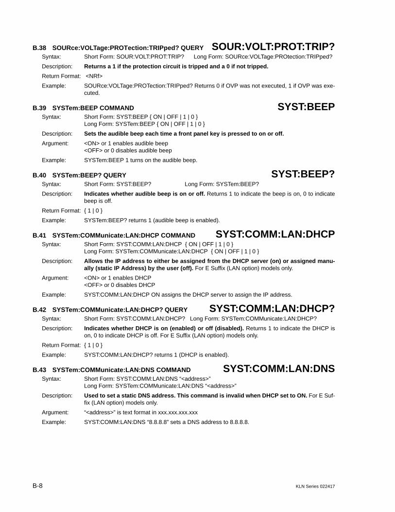
B-8 KLN Series 022417
B.38 SOURce:VOLTage:PROTection:TRIPped? QUERY SOUR:VOLT:PROT:TRIP?Syntax: Short Form: SOUR:VOLT:PROT:TRIP? Long Form: SOURce:VOLTage:PROtection:TRIPped?
Description: Returns a 1 if the protection circuit is tripped and a 0 if not tripped.
Return Format: <NRf>
Example: SOURce:VOLTage:PROTection:TRIPped? Returns 0 if OVP was not executed, 1 if OVP was exe-cuted.
B.39 SYSTem:BEEP COMMAND SYST:BEEPSyntax: Short Form: SYST:BEEP { ON | OFF | 1 | 0 }
Long Form: SYSTem:BEEP { ON | OFF | 1 | 0 }
Description: Sets the audible beep each time a front panel key is pressed to on or off.
Argument: <ON> or 1 enables audible beep<OFF> or 0 disables audible beep
Example: SYSTem:BEEP 1 turns on the audible beep.
B.40 SYSTem:BEEP? QUERY SYST:BEEP?Syntax: Short Form: SYST:BEEP? Long Form: SYSTem:BEEP?
Description: Indicates whether audible beep is on or off. Returns 1 to indicate the beep is on, 0 to indicatebeep is off.
Return Format: { 1 | 0 }
Example: SYSTem:BEEP? returns 1 (audible beep is enabled).
B.41 SYSTem:COMMunicate:LAN:DHCP COMMAND SYST:COMM:LAN:DHCPSyntax: Short Form: SYST:COMM:LAN:DHCP { ON | OFF | 1 | 0 }
Long Form: SYSTem:COMMunicate:LAN:DHCP { ON | OFF | 1 | 0 }
Description: Allows the IP address to either be assigned from the DHCP server (on) or assigned manu-ally (static IP Address) by the user (off). For E Suffix (LAN option) models only.
Argument: <ON> or 1 enables DHCP<OFF> or 0 disables DHCP
Example: SYST:COMM:LAN:DHCP ON assigns the DHCP server to assign the IP address.
B.42 SYSTem:COMMunicate:LAN:DHCP? QUERY SYST:COMM:LAN:DHCP?Syntax: Short Form: SYST:COMM:LAN:DHCP? Long Form: SYSTem:COMMunicate:LAN:DHCP?
Description: Indicates whether DHCP is on (enabled) or off (disabled). Returns 1 to indicate the DHCP ison, 0 to indicate DHCP is off. For E Suffix (LAN option) models only.
Return Format: { 1 | 0 }
Example: SYST:COMM:LAN:DHCP? returns 1 (DHCP is enabled).
B.43 SYSTem:COMMunicate:LAN:DNS COMMAND SYST:COMM:LAN:DNSSyntax: Short Form: SYST:COMM:LAN:DNS “<address>”
Long Form: SYSTem:COMMunicate:LAN:DNS “<address>”
Description: Used to set a static DNS address. This command is invalid when DHCP set to ON. For E Suf-fix (LAN option) models only.
Argument: “<address>” is text format in xxx.xxx.xxx.xxx
Example: SYST:COMM:LAN:DNS “8.8.8.8” sets a DNS address to 8.8.8.8.

KLN Series 022417 B-9
B.44 SYSTem:COMMunicate:LAN:DNS? QUERY SYST:COMM:LAN:DNS?Syntax: Short Form: SYST:COMM:LAN:DNS? Long Form: SYSTem:COMMunicate:LAN:DNS?
Description: Returns the DNS Address. For E Suffix (LAN option) models only.
Return Format: “<address>” is text format in xxx.xxx.xxx.xxx
Example: SYST:COMM:LAN:DNS? returns DNS address “8.8.8.8”.
B.45 SYSTem:COMMunicate:LAN:DNS:AUTO COMMAND SYST:COMM:LAN:DNS:AUTOSyntax: Short Form: SYST:COMM:LAN:DNS:AUTO <bool> { ON | OFF | 1 | 0 }
Long Form: SYSTem:COMMunicate:LAN:DNS:AUTO <bool> { ON | OFF | 1 | 0 }
Description: Used to enable the power supply to automatically obtain the DNS addresses from the DHCPserver. This command is invalid when DHCP set to ON. For E Suffix (LAN option) models only.
Argument: <ON> or 1 enables automatic DNS addresses from DHCP<OFF> or 0 disables automatic DNS addresses from DHCP
Example: SYST:COMM:LAN:DNS:AUTO 1 enables DNS addresses to be obtained automatically fromDHCP.
B.46 SYSTem:COMMunicate:LAN:DNS:AUTO? QUERY SYST:COMM:LAN:DNS:AUTO?Syntax: Short Form: SYST:COMM:LAN:DNS:AUTO?
Long Form: SYSTem:COMMunicate:LAN:DNS:AUTO?
Description: Indicates whether automatic DNS addresses from DHCP is on (enabled) or off (disabled).Returns 1 to indicate the automatic DNS addresses from DHCP is on, 0 to indicate automatic DNSaddresses from DHCP is off. For E Suffix (LAN option) models only.
Return Format: { 1 | 0 }
Example: SYST:COMM:LAN:DNS? returns DNS address “8.8.8.8”.
B.47 SYSTem:COMMunicate:LAN:GATEway COMMAND SYST:COMM:LAN:GATESyntax: Short Form: SYST:COMM:LAN:GATE <address>
Long Form: SYSTem:COMMunicate:LAN:GATEway <address>
Description: Sets a static default gateway address to be used during communication via the LAN inter-face. This command is invalid if DHCP is enabled (on). For E Suffix (LAN option) models only.
Argument: <address> is text format xxx.xxx.xxx.xxx
Example: SYST:COMM:LAN:GATE 192.168.0.1 assigns the static default gateway address to be192.168.0.1.
B.48 SYSTem:COMMunicate:LAN:GATEway? QUERY SYST:COMM:LAN:GATE?Syntax: Short Form: SYST:COMM:LAN:GATE? Long Form: SYSTem:COMMunicate:LAN:GATEway?
Description: Indicates static default gateway address to be used during communication via the LANinterface. For E Suffix (LAN option) models only.
Return Format: <address> is text format xxx.xxx.xxx.xxx
Example: SYST:COMM:LAN:GATE? returns 192.168.0.1 (static default gateway address).
B.49 SYSTem:COMMunicate:LAN:IP COMMAND SYST:COMM:LAN:IPSyntax: Short Form: SYST:COMM:LAN:IP <address>
Long Form: SYSTem:COMMunicate:LAN:IP <address>
Description: Sets the IP address for communication via the LAN interface. Changing this address requiresthat power to the KLN be cycled off, then on. For E Suffix (LAN option) models only.
Argument: <address> is text in the format xxx.xxx.xxx.xxx
Example: SYST:COMM:LAN:IP 192.168.0.100 sets the IP address to 192.168.0.100.

B-10 KLN Series 022417
B.50 SYSTem:COMMunicate:LAN:IP? QUERY SYST:COMM:LAN:IP?Syntax: Short Form: SYST:COMM:LAN:IP? Long Form: SYSTem:COMMunicate:LAN:IP?
Description: Indicates IP address assigned for communication vi the LAN interface. For E Suffix (LANoption) models only.
Return Format: <address> is text in the format xxx.xxx.xxx.xxx
Example: SYST:COMM:LAN:IP? returns 192.168.0.100 to indicate the IP address is set to 192.168.0.100.
B.51 SYSTem:COMMunicate:LAN:IPADdress COMMAND SYST:COMM:LAN:IPADSyntax: Short Form: SYST:COMM:LAN:IPAD <address>
Long Form: SYSTem:COMMunicate:LAN:IPADdress <address>
Description: Sets the static IP address for communication via the LAN interface. Changing this addressrequires that power to the KLN be cycled off, then on. For E Suffix (LAN option) models only.
Argument: <address> is text in the format xxx.xxx.xxx.xxx
Example: SYST:COMM:LAN:IPAD 192.168.0.100 sets the static IP address to 192.168.0.100.
B.52 SYSTem:COMMunicate:LAN:IPADdress? QUERY SYST:COMM:LAN:IPAD?Syntax: Short Form: SYST:COMM:LAN:IPAD? Long Form: SYSTem:COMMunicate:LAN:IPADdress?
Description: Indicates IP static address assigned for communication via the LAN interface. For E Suffix(LAN option) models only.
Return Format: <address> is text in the format xxx.xxx.xxx.xxx
Example: SYST:COMM:LAN:IPAD? returns 192.168.0.100 to indicate the static IP address is set to192.168.0.100.
B.53 SYSTem:COMMunicate:LAN:MAC? QUERY SYST:COMM:LAN:MAC?Syntax: Short Form: SYST:COMM:LAN:MAC? Long Form: SYSTem:COMMunicate:LAN:MAC?
Description: Indicates MAC address assigned for communication via the LAN interface. For E Suffix (LANoption) models only.
Return Format: <string> is text in the format xx-xx-xx-xx-xx-xx.
Example: SYST:COMM:LAN:MAC? returns 70-62-42-00-00-00 to indicate the MAC address is set to 70-62-42-00-00-00.
B.54 SYSTem:COMMunicate:LAN:RESet COMMAND SYST:COMM:LAN:RESSyntax: Short Form: SYST:COMM:LAN:RES
Long Form: SYSTem:COMMunicate:LAN:RESet
Description: Resets the LAN settings used for communication via the LAN interface to the factorydefaults. This includes the IP address and hostname, so LAN communications could be lost. Fac-tory default LAN settings are: DHCP set to On and IP address set to 192.168.0.100. For E Suffix(LAN option) models only.
Argument: none
Example: SYST:COMM:LAN:RES resets LAN settings to factor defaults described above.
B.55 SYSTem:COMMunicate:LAN:SMAS COMMAND SYST:COMM:LAN:SMASSyntax: Short Form: SYST:COMM:LAN:SMAS <address>
Long Form: SYSTem:COMMunicate:LAN:SMAS <address>
Description: Sets the Subnet Mask address for communication via the LAN interface. Changing thisaddress requires that power to the KLN be cycled off, then on. For E Suffix (LAN option) modelsonly.
Argument: <address> is text in the format xxx.xxx.xxx.xxx
Example: SYST:COMM:LAN:SMAS 255.255.0.0 sets the Subnet Mask address to 255.255.0.0.

KLN Series 022417 B-11
B.56 SYSTem:COMMunicate:LAN:SMAS? QUERY SYST:COMM:LAN:SMAS?Syntax: Short Form: SYST:COMM:LAN:SMAS?Long Form: SYSTem:COMMunicate:LAN:SMAS?
Description: Indicates Subnet Mask address assigned for communication via the LAN interface. For ESuffix (LAN option) models only.
Return Format: <address> is text in the format xxx.xxx.xxx.xxx
Example: SYST:COMM:LAN:IP? returns 255.255.0.0 to indicate the Subnet Mask address is set to255.255.0.0.
B.57 SYSTem:COMMunicate:LAN:TELnet:PORT COMMAND SYST:COMM:LAN:TEL:PORTSyntax: Short Form: SYST:COMM:LAN:TEL:PORT <NR1>
Long Form: SYSTem:COMMunicate:LAN:TELnet:PORT <NR1>
Description: Assigns port to be used for Telnet communication via the LAN interface. KLN units use port5025 for Telnet sessions. Changing this address requires that power to the KLN be cycled off, thenon. For E Suffix (LAN option) models only.
Argument: <NR1> in text format, a number from 0 to 65535
Example: SYST:COMM:LAN:TEL:PORT 5025 assigns port 5025 to be used during Telnet sessions. A Telnetsession can typically be started from a host computer shell by sending the IP address followed bythe port number, e.g., telnet 192.168.0.100 5025.
B.58 SYSTem:COMMunicate:LAN:TELnet:PORT? QUERY SYST:COMM:LAN:TEL:PORT?Syntax: Short Form: SYST:COMM:LAN:TEL:PORT?
Long Form: SYSTem:COMMunicate:LAN:TELnet:PORT?
Description: Indicates port assigned for Telnet communication via the LAN interface. For E Suffix (LANoption) models only.
Return Format: <NR1> in text format, a number from 0 to 65535
Example: SYST:COMM:LAN:TEL:PORT? returns 5025 to indicate port 5025 is assigned to be used duringTelnet sessions.
B.59 SYSTem:ERRor? QUERY SYST:ERR?Syntax: Short Form: SYST:ERR? Long Form: SYSTem:ERRor?
Description: Returns error codes and messages.
Return Format: <string> is text format in -XXX XXXXXXXXXXXXX
Example: Input command S0URce:VOLTage 2w will cause error. SYSTem:ERR? returns error code “-138,”and sending SYSTem:ERR? again returns no error code “+0,”. Refer to Table for a complete list oferror codes.
TABLE B-2. ERROR CODESError Code Explanation
0,“No error” No error
72, “OVP” Overvoltage protection error:a. The output voltage exceeds the OVP value.b. The Analog Programming input for output voltage setting is too high (higher than OVP value).
73, “OCP” Output current exceeds 110% of rated current, this OCP value is restricted by hardware and not adjustable.
74, “REMOTE SENSE OVER” The max. compensation voltage is 5V d-c (the sum of two wires, i.e. 2.5V d-c for each).
75, ““D2D Module 1 fault” DC to DC converter module number 1 failed (only one module in 750W models).
76, ““D2D Module 2 fault” DC to DC converter module number 2 failed (two modules in 1500W models).

B-12 KLN Series 022417
B.60 SYSTem:KLOCk COMMAND SYST:KLOCSyntax: Short Form: SYST:KLOC { ON | OFF | 1 | 0 } Long Form: SYSTem:KLOCk { ON | OFF | 1 | 0 }
Description: Disables front panel keys and encoder. Pressing SHIFT/LOC key on the front panel restoresfunctionality to front panel keys and encoder
Argument: <ON> or 1 keys are locked.<OFF> or 0 key are unlocked.
Example: SYSTem:KLOCk 1 disables the front panel keys and encoder.
B.61 SYSTem:KLOCk? QUERY SYST:KLOC?Syntax: Short Form: SYST:KLOC? Long Form: SYSTem:KLOCk?
Description: Indicates whether front panel keys and encoder are enabled or disabled. Returns 1 to indi-cate keys are enabled, 0 to indicated keys are disabled.
Return Format: { 1 | 0 }
77, “Analog shut-off shutdown” a. The slave unit(s) failed when operating in parallel/series.b. Pins 23 and Pin 24 of Analog Programming Port are shorted to shut-off the output.
78, “Software OCP” Software overcurrent protection error: The output current exceeds the set OCP value (adjustable manually or remotely) for more than 1 second.
79, “AC Fault“ Ac line input abnormal
83, “FAN failed” One or more fan failed.
84, “D2D Module 3 fault” DC to DC converter module number 3 failed (four modules in 3000W models).
85, “D2D Module 4 fault” DC to DC converter module number 4 failed (four modules in 3000W models).
-102, “Syntax error” An unrecognized command or data type was encountered; for example, a string was received when the device does not accept strings.
-104, “Data type error” The parser recognized a data element different than one allowed; for example, numeric or string data was expected but block data was encountered.
-109, “Missing parameter” Fewer parameters were received than required for the header; for example, the SYST:BEEP command requires one parameter, so SYST:BEEP is not allowed, while SYST:BEEP ON is allowed.
-221, “Settings confect” Indicates that a legal program data element was parsed but could not be executed due to the current device state
-222, “Data out of range” Indicates that a legal program data element was parsed but could not be executed because the interpreted value was outside the legal range as defined by the device.
-223, “Too much data” Indicates that a legal program data element of block, expression, or string type was received that contained more data than the device could handle due to memory or related device-specific requirements.
-224, “Illegal parameter valid” Used where exact value was expected. from a list of possible values.
-241, “Hardware missing” Indicates that a legal program command or query could not be executed because of missing device hardware; for example, an option was not installed.
-313, “Calibration memory lost” Indicates that nonvolatile calibration data used by the *CAL? command has been lost.
-430, “Query Deadlocked” Indicates that a condition causing an Deadlocked Query error occurred for example, both input buffer and output buffer are full and the device cannot continue.
-440, “Query Unterminated after indefinite response”
Indicates that a query was received in the same program message after a query requesting an indefinite response was executed
-500 OVP Setting too low The OVP setting value is lower than output setting value. Error code generated but power unit remains in present condition.
-599, “IP conflict” The desired IP address already exists on the network.
TABLE B-2. ERROR CODES (CONTINUED)

KLN Series 022417 B-13/(B-14 Blank)
Example: SYSTem:KLOCk? returns 1 (front panel keys and encoder are unlocked).
B.62 SYSTem:LOCal COMMAND SYST:LOCSyntax: Short Form: SYST:LOC Long Form: SYSTem:LOCal
Description: Sets the power supply to be in local mode. The front panel [REMOTE] indicator goes off andthe front panel keys and encoder are enabled.
Argument: None
Example: SYSTem:LOCal puts the power supply in local mode.
B.63 SYSTem:REMote COMMAND SYST:REMSyntax: Short Form: SYST:REM Long Form: SYSTem:REMote
Description: Sets the power supply to be in remote mode. The front panel [REMOTE] indicator lights and thefront panel keys and encoder are disabled. Pressing SHIFT/LOC key on the front panel restoresthe unit to local mode.
Argument: None
Example: SYSTem:REMote puts the power supply in remote mode.
B.64 SYSTem:VERSion? QUERY SYST:VERS?Syntax: Short Form: SYST:VERS? Long Form: SYSTem:VERSion?
Description: Indicates the SCPI version to which unit complies.
Return Format: <string> where <string> is text in XXXX.X format corresponding to SCPI year and revision.
Example: SYSTem:VERSion? returns 1990.0 (unit complies with SCPI version 1990.0.)
