optical amp
TRANSCRIPT
1Prof. Z Ghassemlooy
Optical Fibre Communication Systems
Professor Z Ghassemlooy
Lecture 5 – Optical Amplifier
Optical Communications Research GroupNorthumbria Communications Research Laboratory
School of Computing, Engineering andInformation Sciences
The University of NorthumbriaU.K.
http://soe.unn.ac.uk/ocr
2Prof. Z Ghassemlooy
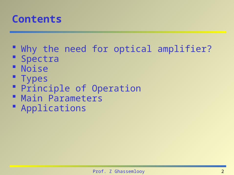
Contents
Why the need for optical amplifier? Spectra Noise Types Principle of Operation Main Parameters Applications
3Prof. Z Ghassemlooy
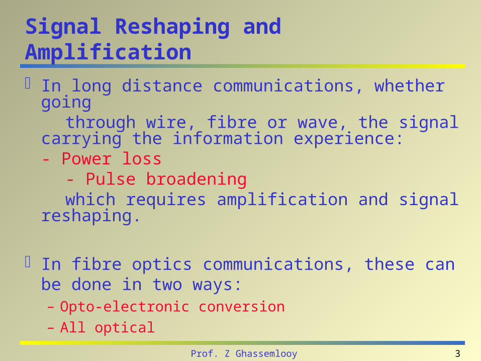
Signal Reshaping and Amplification
In long distance communications, whether going through wire, fibre or wave, the signal carrying the
information experience:- Power loss
- Pulse broadening which requires amplification and signal reshaping.
In fibre optics communications, these can be done in two ways:– Opto-electronic conversion
– All optical
4Prof. Z Ghassemlooy
Signal Reshaping and Amplification
Depending on its nature, a signal can also be regenerated.
A digital signal is made of 1's and 0's: it is possible to reconstruct the signal and amplify it at the same time.
An analog signal however, cannot be reconstructed because nobody knows what the original signal looked like.
5Prof. Z Ghassemlooy
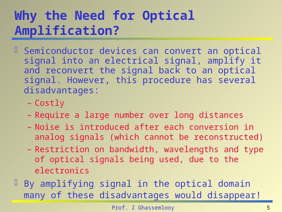
Why the Need for Optical Amplification?
Semiconductor devices can convert an optical signal into an electrical signal, amplify it and reconvert the signal back to an optical signal. However, this procedure has several disadvantages: – Costly
– Require a large number over long distances
– Noise is introduced after each conversion in analog signals (which cannot be reconstructed)
– Restriction on bandwidth, wavelengths and type of optical signals being used, due to the electronics
By amplifying signal in the optical domain many of these disadvantages would disappear!
6Prof. Z Ghassemlooy
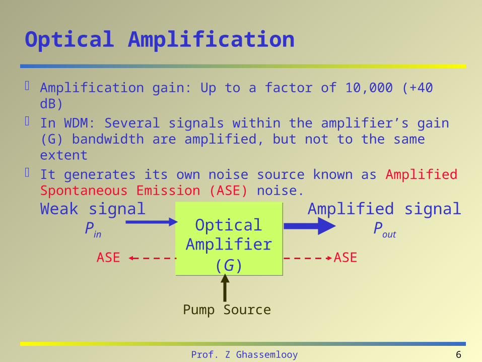
Optical Amplification
Amplification gain: Up to a factor of 10,000 (+40 dB) In WDM: Several signals within the amplifier’s gain (G)
bandwidth are amplified, but not to the same extent It generates its own noise source known as Amplified
Spontaneous Emission (ASE) noise.
Optical Amplifier
(G)
Optical Amplifier
(G)
Weak signalPin
Amplified signalPout
ASE ASE
Pump Source
7Prof. Z Ghassemlooy
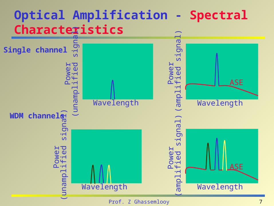
Optical Amplification - Spectral Characteristics
Wavelength
Pow
er
(una
mpl
ifie
d si
gnal
)
Wavelength
Pow
er
(am
plif
ied
sign
al)
ASE
Wavelength
Pow
er
(una
mpl
ifie
d si
gnal
)
Wavelength
Pow
er
(am
plif
ied
sign
al)
ASE
Single channel
WDM channels
8Prof. Z Ghassemlooy
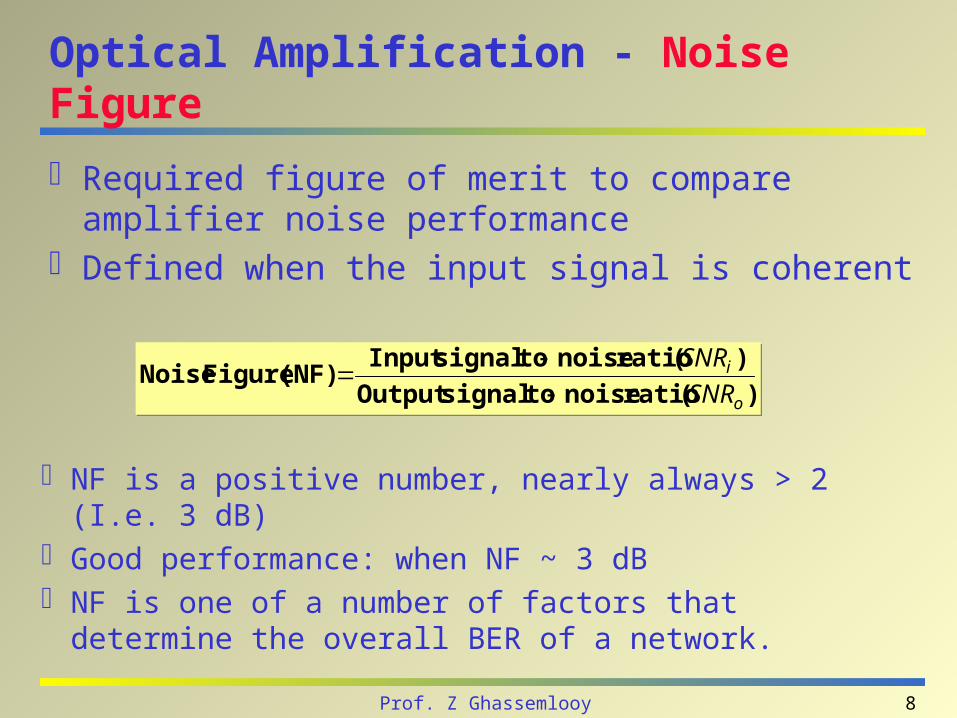
Optical Amplification - Noise Figure
Required figure of merit to compare amplifier noise performance
Defined when the input signal is coherent
)(rationoisetosignalOutput
)(rationoisetosignalInput(NF)FigureNoise
o
i
SNR
SNR
)(rationoisetosignalOutput
)(rationoisetosignalInput(NF)FigureNoise
o
i
SNR
SNR
NF is a positive number, nearly always > 2 (I.e. 3 dB) Good performance: when NF ~ 3 dB NF is one of a number of factors that determine the
overall BER of a network.
9Prof. Z Ghassemlooy
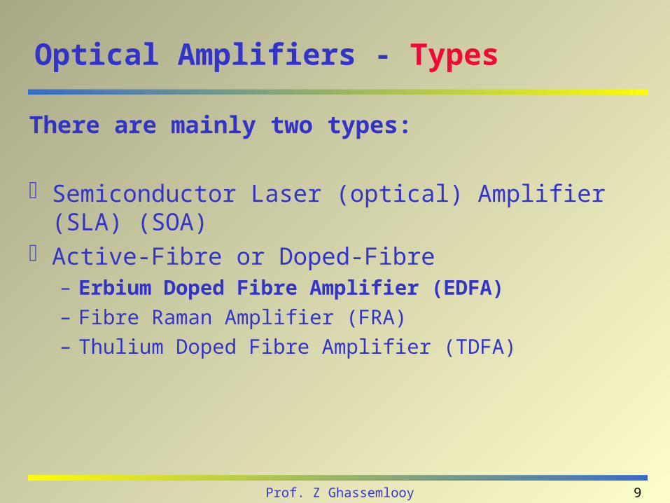
Optical Amplifiers - Types
There are mainly two types:
Semiconductor Laser (optical) Amplifier (SLA) (SOA) Active-Fibre or Doped-Fibre
– Erbium Doped Fibre Amplifier (EDFA)
– Fibre Raman Amplifier (FRA)
– Thulium Doped Fibre Amplifier (TDFA)
10Prof. Z Ghassemlooy
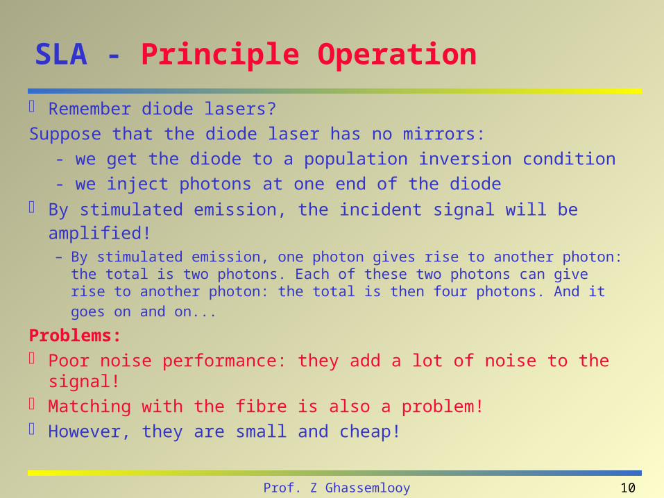
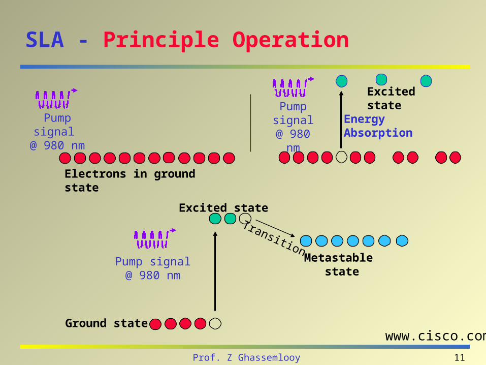
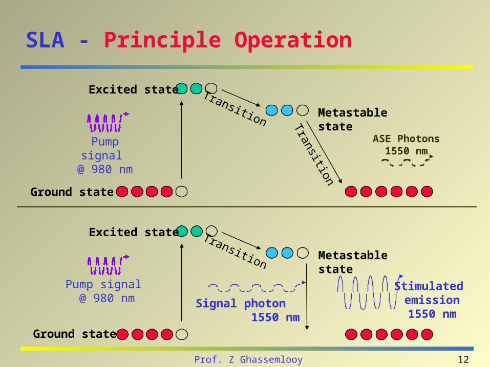
SLA - Principle Operation
Remember diode lasers?
Suppose that the diode laser has no mirrors:
- we get the diode to a population inversion condition
- we inject photons at one end of the diode
By stimulated emission, the incident signal will be amplified! – By stimulated emission, one photon gives rise to another photon: the total
is two photons. Each of these two photons can give rise to another photon:
the total is then four photons. And it goes on and on...
Problems: Poor noise performance: they add a lot of noise to the signal! Matching with the fibre is also a problem! However, they are small and cheap!
11Prof. Z Ghassemlooy
SLA - Principle Operation
Electrons in ground state
Pump signal @ 980 nm Energy Absorption
Excited statePump signal @ 980
nm
TransitionMetastable
state
Excited state
Ground state
Pump signal @ 980 nm
www.cisco.com
12Prof. Z Ghassemlooy
SLA - Principle Operation
ASE Photons1550 nm
Ground state
Excited state
Metastable stateTransition
Transition
Pump signal @ 980 nm
Excited state
Metastable stateTransition
Pump signal @ 980 nm
Stimulated emission1550 nm
Signal photon 1550 nm
Ground state
13Prof. Z Ghassemlooy
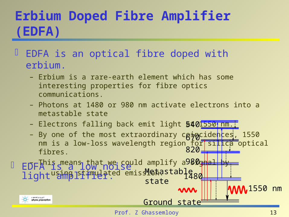
Erbium Doped Fibre Amplifier (EDFA)
EDFA is an optical fibre doped with erbium. – Erbium is a rare-earth element which has some interesting properties for fibre
optics communications.
– Photons at 1480 or 980 nm activate electrons into a metastable state
– Electrons falling back emit light at 1550 nm.
– By one of the most extraordinary coincidences, 1550 nm is a low-loss wavelength region for silica optical fibres.
– This means that we could amplify a signal by
using stimulated emission.
1480
980
820
540
670
Ground state
Metastablestate
1550 nm
EDFA is a low noise light amplifier.
14Prof. Z Ghassemlooy
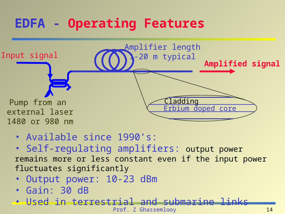
EDFA - Operating Features
• Available since 1990’s:• Self-regulating amplifiers: output power remains more or less constant even if the input power fluctuates significantly• Output power: 10-23 dBm• Gain: 30 dB• Used in terrestrial and submarine links
Input signal
Pump from an external laser
1480 or 980 nm
Erbium doped coreCladding
Amplifier length1-20 m typical
Amplified signal
15Prof. Z Ghassemlooy
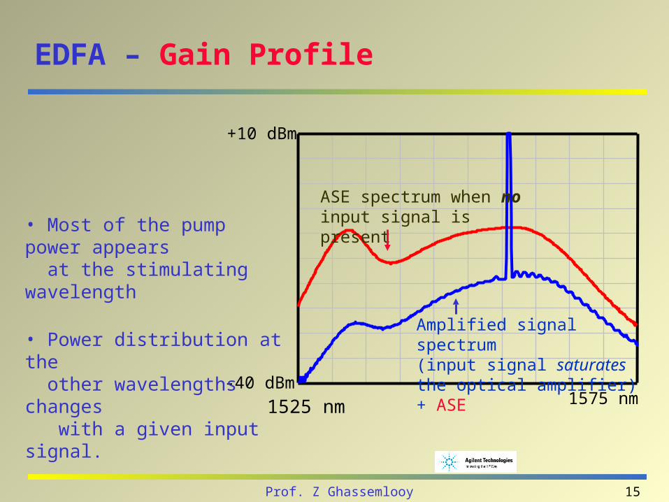
EDFA – Gain Profile
ASE spectrum when no input signal is present
Amplified signal spectrum(input signal saturates the optical amplifier) + ASE
1575 nm-40 dBm
1525 nm
+10 dBm
• Most of the pump power appears at the stimulating wavelength
• Power distribution at the other wavelengths changes with a given input signal.
16Prof. Z Ghassemlooy
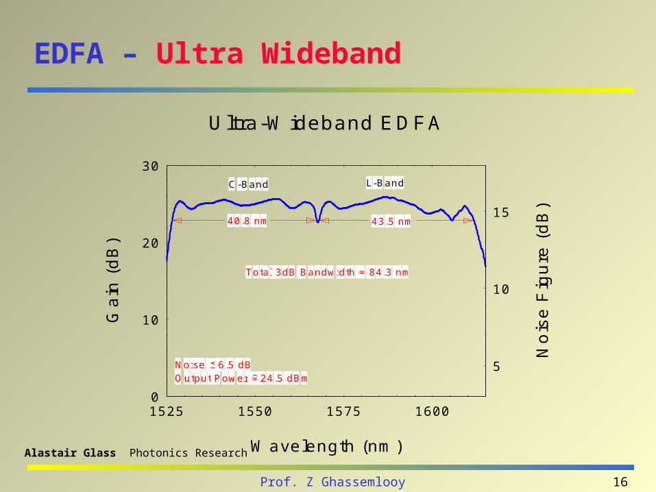
EDFA – Ultra Wideband
0
10
20
30
1525 1550 1575 1600
5
10
15
Noise 6.5 dBOutput Power 24.5 dBm
L-BandC-Band
Total 3dB Bandwidth = 84.3 nm
43.5 nm40.8 nm
Wavelength (nm)
Ga
in (
dB
)
No
ise
Fig
ure
(d
B)
Ultra-Wideband EDFA
Alastair Glass Photonics Research
17Prof. Z Ghassemlooy
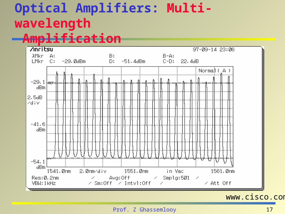
Optical Amplifiers: Multi-wavelength Amplification
www.cisco.com
18Prof. Z Ghassemlooy
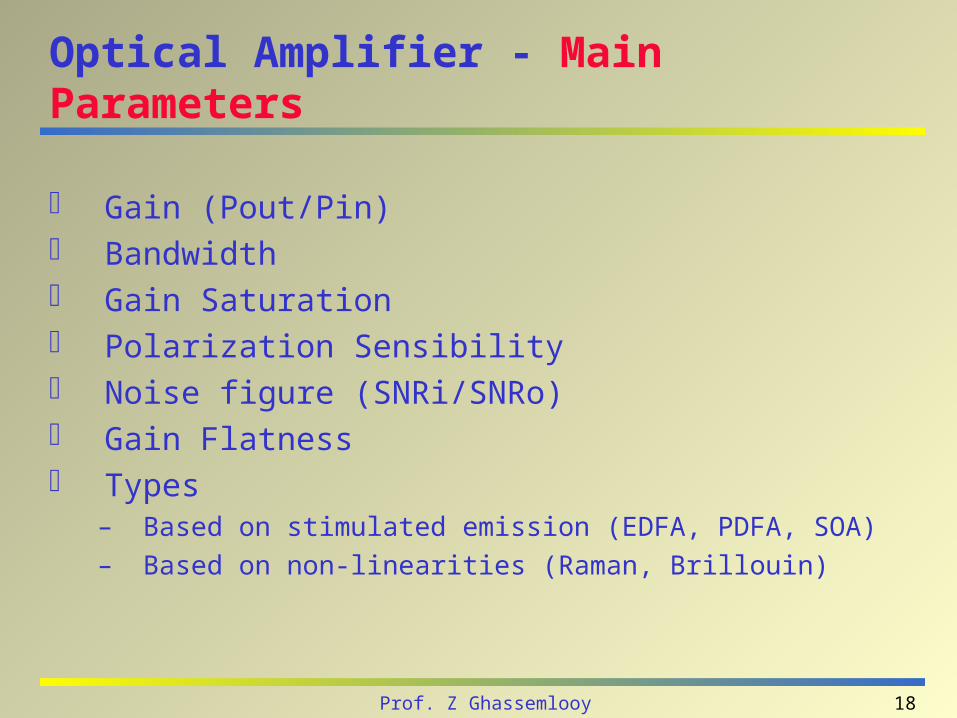
Optical Amplifier - Main Parameters
Gain (Pout/Pin) Bandwidth Gain Saturation Polarization Sensibility Noise figure (SNRi/SNRo) Gain Flatness Types
– Based on stimulated emission (EDFA, PDFA, SOA)– Based on non-linearities (Raman, Brillouin)
19Prof. Z Ghassemlooy
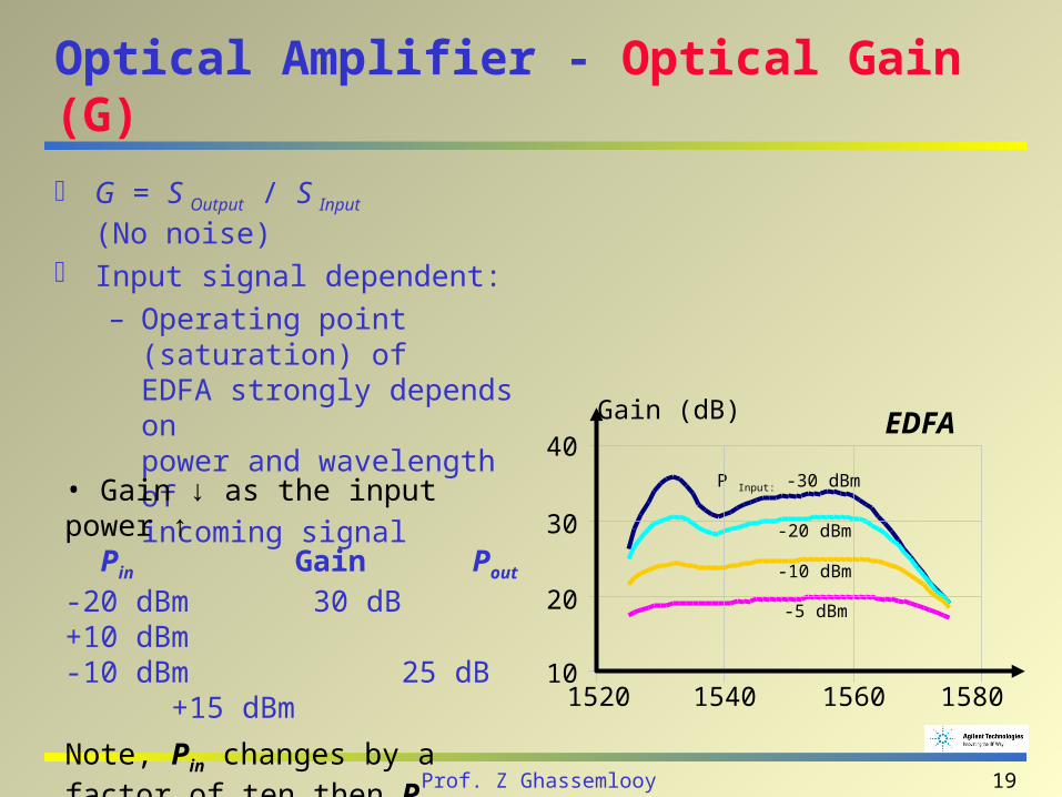
Optical Amplifier - Optical Gain (G)
G = S Output / S Input (No noise)
Input signal dependent:
– Operating point (saturation) ofEDFA strongly depends on power and wavelength ofincoming signal
Gain (dB)
1540 1560 158010
1520
20
40
30
-5 dBm
-20 dBm
-10 dBm
P Input: -30 dBm• Gain ↓ as the input power ↑ Pin Gain Pout
-20 dBm 30 dB +10 dBm-10 dBm 25 dB +15 dBm
Note, Pin changes by a factor of ten then Pout changes only by a factor of three in this power range.
EDFA
20Prof. Z Ghassemlooy
Optical Amplifier - Optical Gain (G)
Gain bandwidth– Refers to the range of frequencies or wavelengths over which the
amplifier is effective.
– In a network, the gain bandwidth limits the number of wavelengths available for a given channel spacing.
• Gain efficiency- Measures the gain as a function of input power in dB/mW.
• Gain saturation- Is the value of output power at which the output power no longer increases with an increase in the input power. - The saturation power is typically defined as the output power at which there is a 3-dB reduction in the ratio of output power to input power (the small-signal gain).
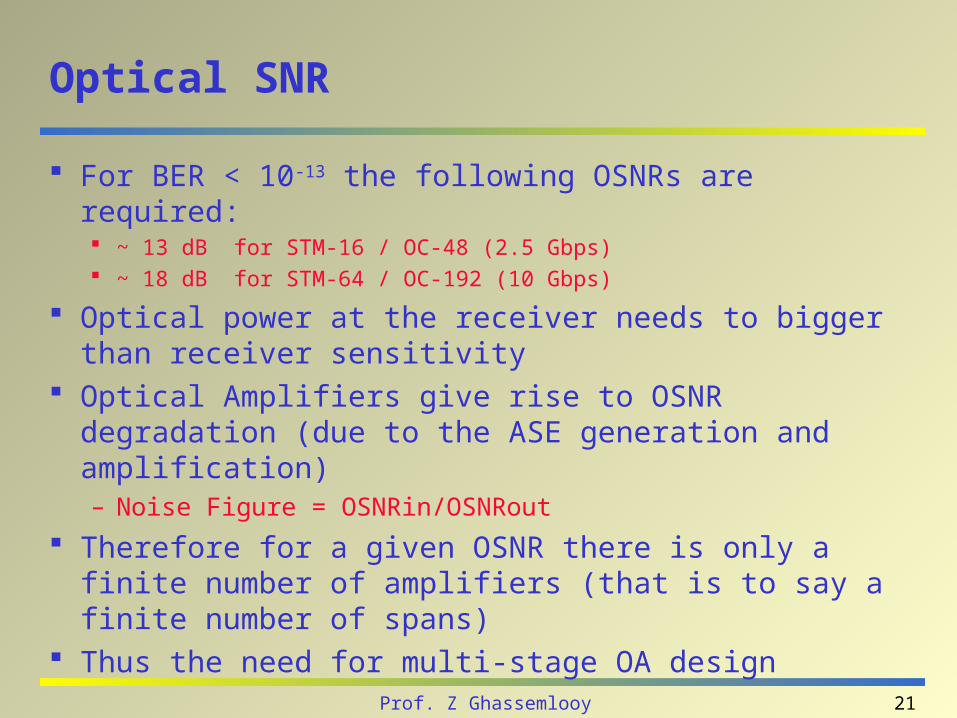
21Prof. Z Ghassemlooy
Optical SNR
For BER < 10-13 the following OSNRs are required: ~ 13 dB for STM-16 / OC-48 (2.5 Gbps) ~ 18 dB for STM-64 / OC-192 (10 Gbps)
Optical power at the receiver needs to bigger than receiver sensitivity
Optical Amplifiers give rise to OSNR degradation (due to the ASE generation and amplification)– Noise Figure = OSNRin/OSNRout
Therefore for a given OSNR there is only a finite number of amplifiers (that is to say a finite number of spans)
Thus the need for multi-stage OA design

22Prof. Z Ghassemlooy
Optical Amplifiers: Multi-Stage
NFtotal = NF1+NF2/G1
NF 1st/2nd stage = Pin - SNRo [dB] - 10 Log (hc2 / 3)
Er3+
Doped Fiber
PumpPump PumpPump
Input Signal Output Signal
OpticalIsolator
1st Active stage co-pumped: optimized for low noise figure
2nd stage counter-pumped: optimized for high output power
23Prof. Z Ghassemlooy
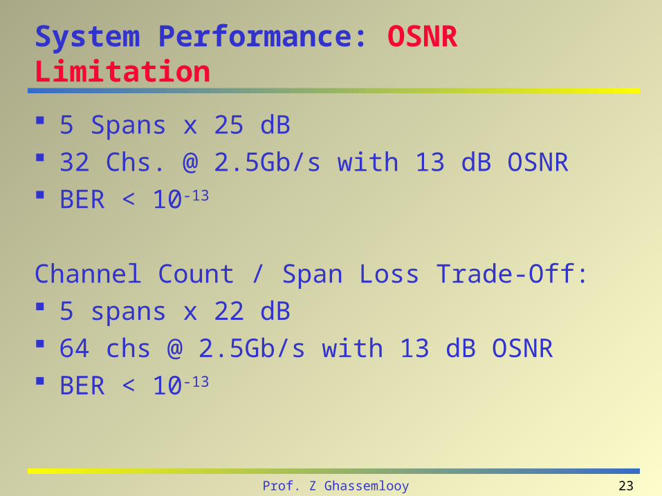
System Performance: OSNR Limitation
5 Spans x 25 dB 32 Chs. @ 2.5Gb/s with 13 dB OSNR BER < 10-13
Channel Count / Span Loss Trade-Off: 5 spans x 22 dB 64 chs @ 2.5Gb/s with 13 dB OSNR BER < 10-13
24Prof. Z Ghassemlooy
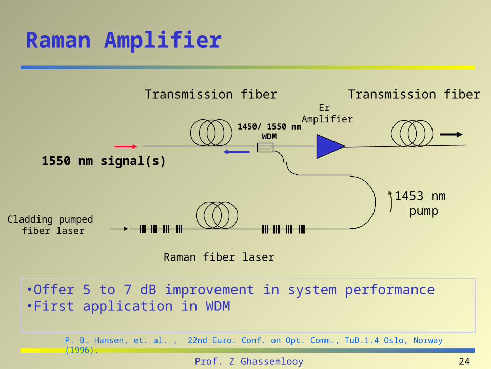
Raman Amplifier
P. B. Hansen, et. al. , 22nd Euro. Conf. on Opt. Comm., TuD.1.4 Oslo, Norway (1996).
Transmission fiber
1550 nm signal(s)
Cladding pumped fiber laser
1450/ 1550 nm WDM
1453 nm pump
ErAmplifier
Raman fiber laser
Transmission fiber
•Offer 5 to 7 dB improvement in system performance •First application in WDM
25Prof. Z Ghassemlooy
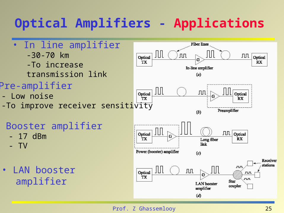
Optical Amplifiers - Applications
• In line amplifier-30-70 km-To increase transmission link
• Pre-amplifier- Low noise-To improve receiver sensitivity
• Booster amplifier- 17 dBm- TV
• LAN booster amplifier