optical microscopy: lecture 2 magnification and … · optical microscopy: lecture 2 magnification...
TRANSCRIPT
GG 711: Advanced Techniques in Geophysics and Materials Science
Pavel Zinin HIGP, University of Hawaii, Honolulu, USA
Optical Microscopy: Lecture 2
Magnification and Resolution in Optical Microscopy
www.soest.hawaii.edu\~zinin
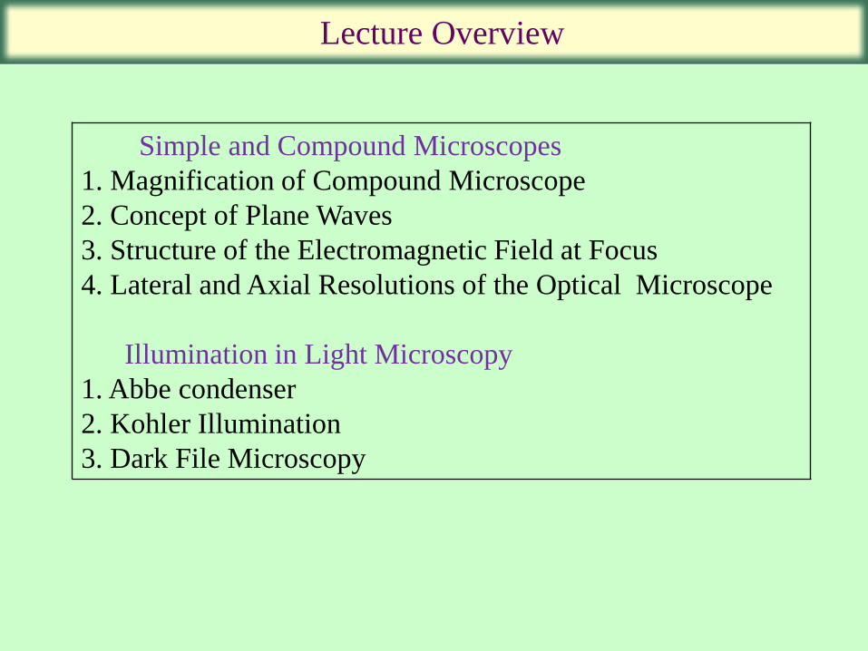
Lecture Overview
Simple and Compound Microscopes
1. Magnification of Compound Microscope
2. Concept of Plane Waves
3. Structure of the Electromagnetic Field at Focus
4. Lateral and Axial Resolutions of the Optical Microscope
Illumination in Light Microscopy
1. Abbe condenser
2. Kohler Illumination
3. Dark File Microscopy
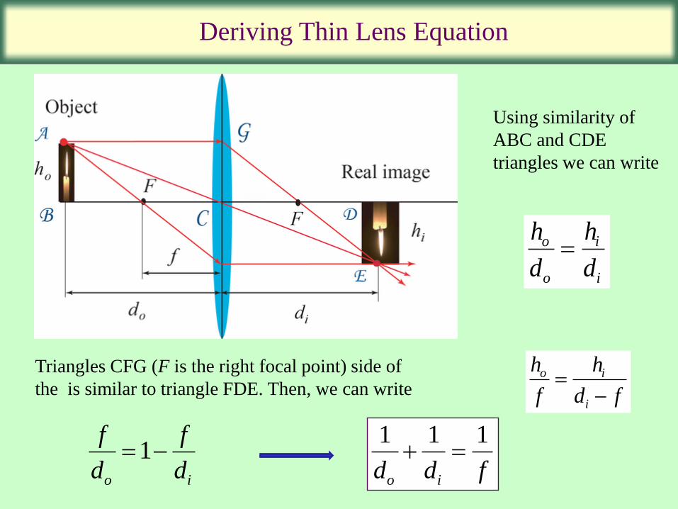
Refraction Deriving Thin Lens Equation
1 1 1
o id d f
Using similarity of
ABC and CDE
triangles we can write
Triangles CFG (F is the right focal point) side of
the is similar to triangle FDE. Then, we can write
1o i
f f
d d
h
d
h
d
o
o
i
i
h
f
h
d f
o i
i
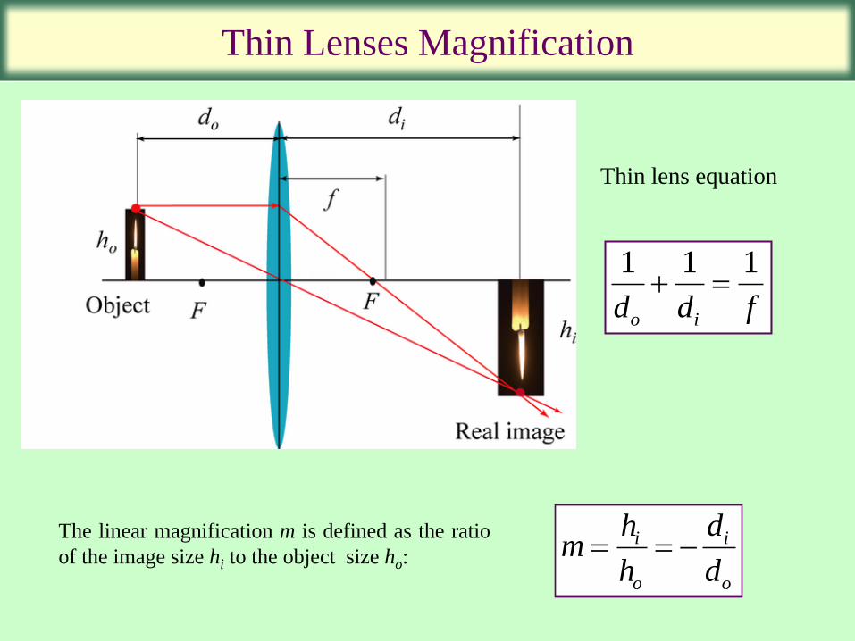
Refraction Thin Lenses Magnification
i i
o o
h dm
h d
Thin lens equation
1 1 1
o id d f
The linear magnification m is defined as the ratio
of the image size hi to the object size ho:
Refraction Magnification of the Human Eye
S. Bradbury. An Introduction to the Optical Microscope. Royal Microscopical Society, 1984
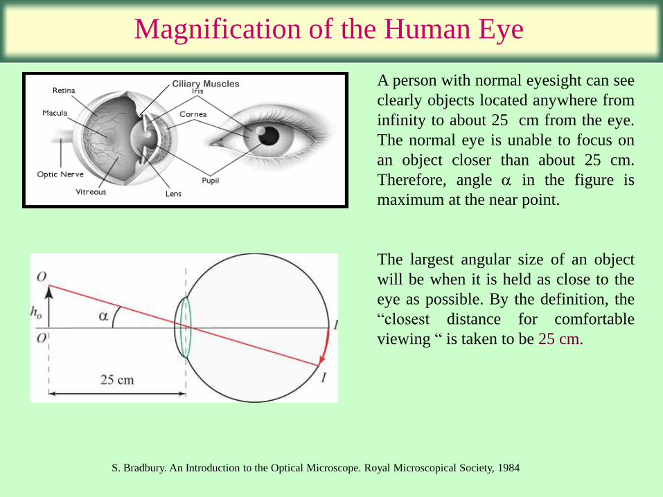
A person with normal eyesight can see
clearly objects located anywhere from
infinity to about 25 cm from the eye.
The normal eye is unable to focus on
an object closer than about 25 cm.
Therefore, angle in the figure is
maximum at the near point.
The largest angular size of an object
will be when it is held as close to the
eye as possible. By the definition, the
“closest distance for comfortable
viewing “ is taken to be 25 cm.
Ciliary Muscles
Refraction Magnification of the Human Eye
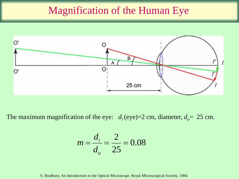
The maximum magnification of the eye: di (eye)=2 cm, diameter, do= 25 cm.
20.08
25
i
o
dm
d
S. Bradbury. An Introduction to the Optical Microscope. Royal Microscopical Society, 1984
Magnifying Lens
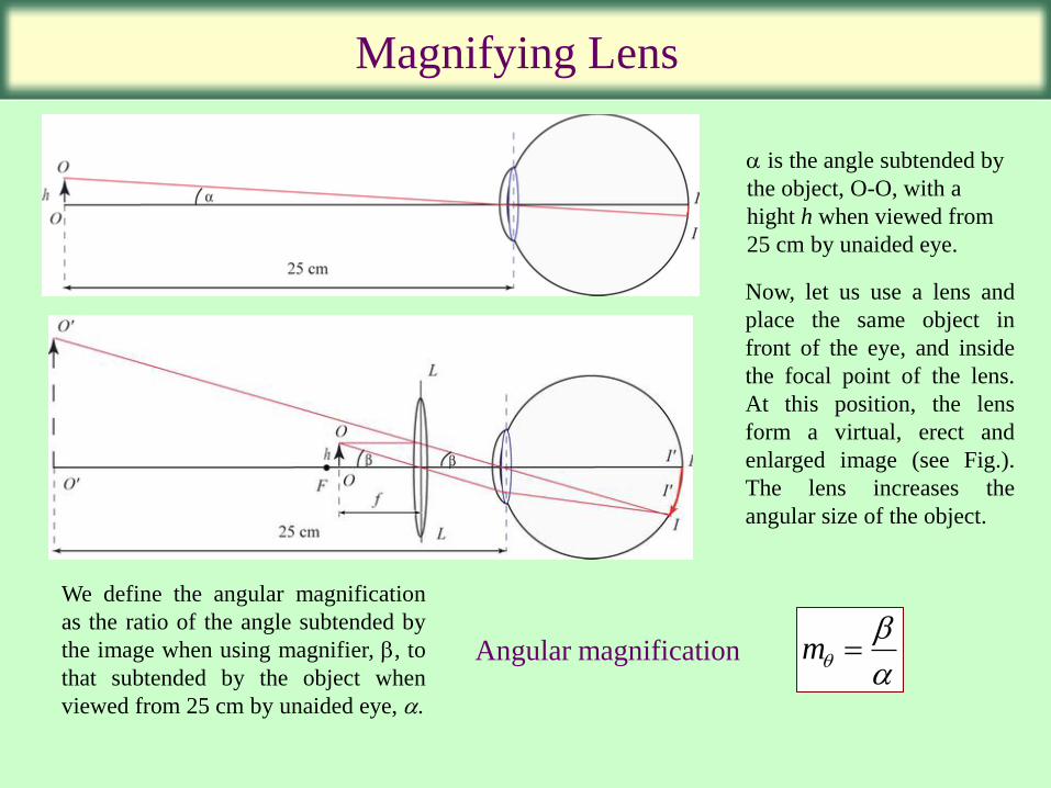
is the angle subtended by
the object, O-O, with a
hight h when viewed from
25 cm by unaided eye.
Now, let us use a lens and
place the same object in
front of the eye, and inside
the focal point of the lens.
At this position, the lens
form a virtual, erect and
enlarged image (see Fig.).
The lens increases the
angular size of the object.
Angular magnification
We define the angular magnification
as the ratio of the angle subtended by
the image when using magnifier, , to
that subtended by the object when
viewed from 25 cm by unaided eye, .
m
Simple microscope
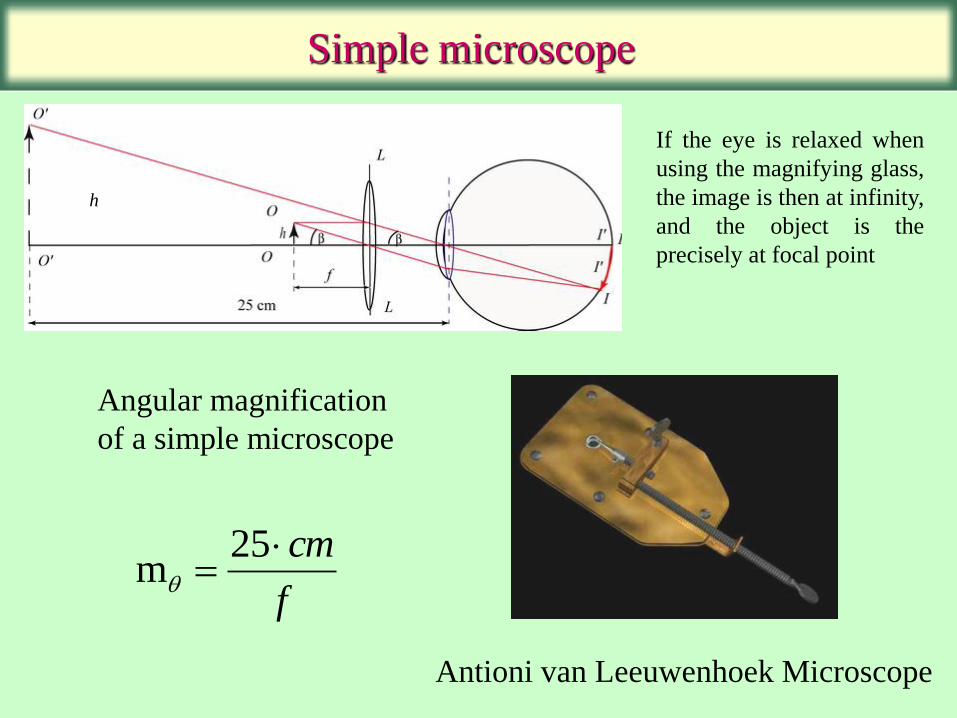
If the eye is relaxed when
using the magnifying glass,
the image is then at infinity,
and the object is the
precisely at focal point
f
cm
25m
h
Antioni van Leeuwenhoek Microscope
Angular magnification
of a simple microscope

Magnification in Compound Microscope
Image is virtual m
h
h
L f f
f
L
fo
o
o
o e
o o
1
mcm
fe
e
25
Since magnification of the eye piece is
m m mL cm
f fo e
o e
25
L f fo ,
Let us place the object, O,
outside the focal lens of the
objective. The image OI is real
and enlarged. The magnification
of the first image is
Mo=di/do.
Compound Microscopes
1 1 1
o e od L f f
1 1 1
1
o o e
e o
o e o
o
d f L f
L f f L
f L f f L
f
do
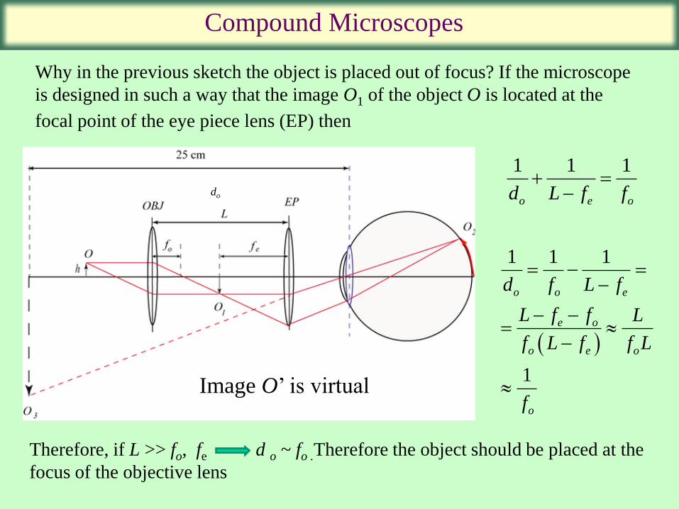
Image O’ is virtual
Why in the previous sketch the object is placed out of focus? If the microscope
is designed in such a way that the image O1 of the object O is located at the
focal point of the eye piece lens (EP) then
Therefore, if L >> fo, fe d o ~ fo .Therefore the object should be placed at the
focus of the objective lens

Resolution in Microscopy
Young’s Double-Slit Experiment indicated light behaved as a wave
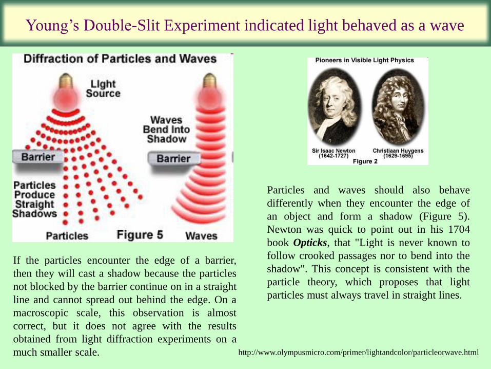
Particles and waves should also behave
differently when they encounter the edge of
an object and form a shadow (Figure 5).
Newton was quick to point out in his 1704
book Opticks, that "Light is never known to
follow crooked passages nor to bend into the
shadow". This concept is consistent with the
particle theory, which proposes that light
particles must always travel in straight lines.
http://www.olympusmicro.com/primer/lightandcolor/particleorwave.html
If the particles encounter the edge of a barrier,
then they will cast a shadow because the particles
not blocked by the barrier continue on in a straight
line and cannot spread out behind the edge. On a
macroscopic scale, this observation is almost
correct, but it does not agree with the results
obtained from light diffraction experiments on a
much smaller scale.
Young’s Double-Slit Experiment indicated light behaved as a wave
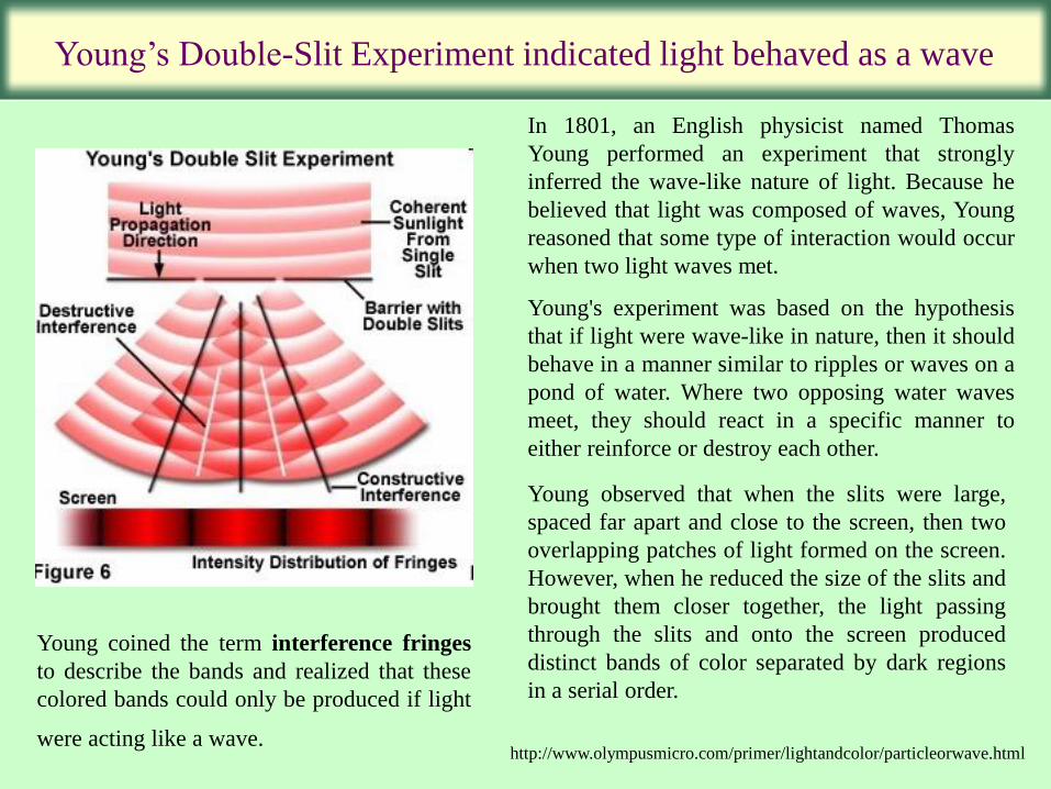
In 1801, an English physicist named Thomas
Young performed an experiment that strongly
inferred the wave-like nature of light. Because he
believed that light was composed of waves, Young
reasoned that some type of interaction would occur
when two light waves met.
Young's experiment was based on the hypothesis
that if light were wave-like in nature, then it should
behave in a manner similar to ripples or waves on a
pond of water. Where two opposing water waves
meet, they should react in a specific manner to
either reinforce or destroy each other.
Young observed that when the slits were large,
spaced far apart and close to the screen, then two
overlapping patches of light formed on the screen.
However, when he reduced the size of the slits and
brought them closer together, the light passing
through the slits and onto the screen produced
distinct bands of color separated by dark regions
in a serial order.
Young coined the term interference fringes
to describe the bands and realized that these
colored bands could only be produced if light
were acting like a wave. http://www.olympusmicro.com/primer/lightandcolor/particleorwave.html
Plane Wave: Definition
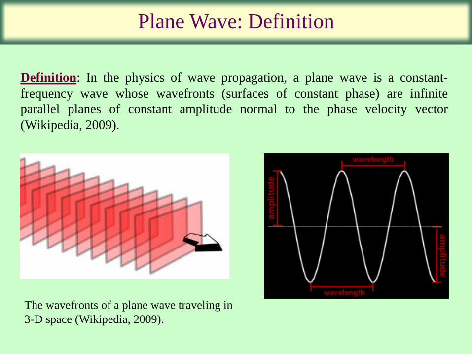
Definition: In the physics of wave propagation, a plane wave is a constant-
frequency wave whose wavefronts (surfaces of constant phase) are infinite
parallel planes of constant amplitude normal to the phase velocity vector
(Wikipedia, 2009).
The wavefronts of a plane wave traveling in
3-D space (Wikipedia, 2009).
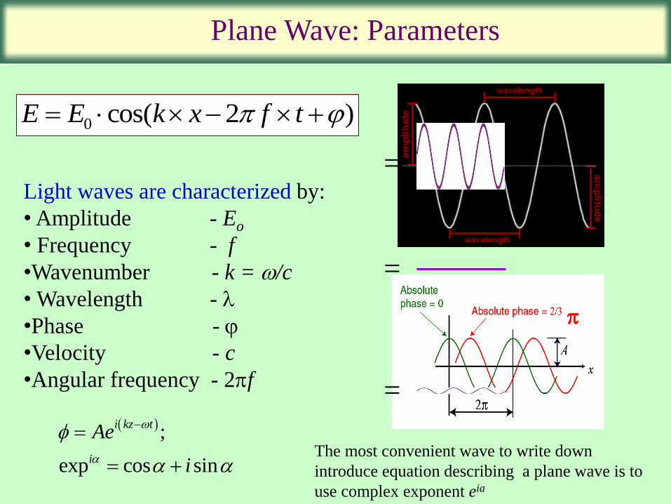
Plane Wave: Parameters
Light waves are characterized by:
• Amplitude - Eo
• Frequency - f
•Wavenumber - k = /c
• Wavelength - l
•Phase -
•Velocity - c
•Angular frequency - 2f
0 cos( 2 )E E k x f t
;
exp cos sin
i kz t
i
Ae
i
The most convenient wave to write down
introduce equation describing a plane wave is to
use complex exponent eia
=
=
=
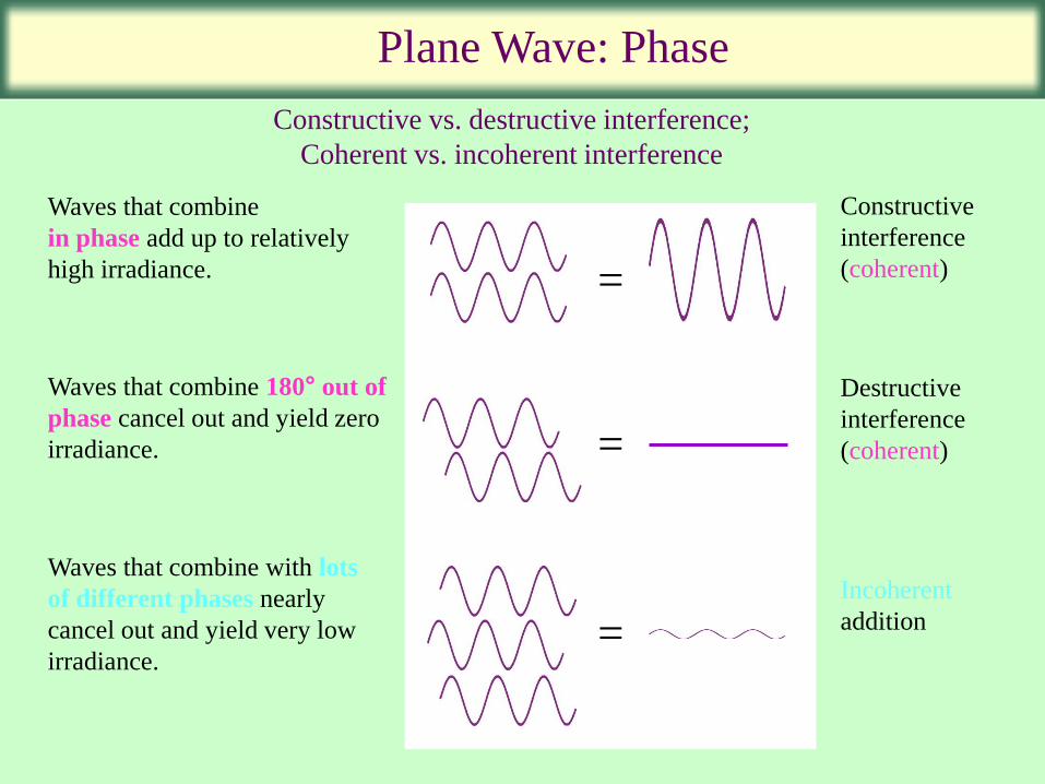
Plane Wave: Phase
Constructive vs. destructive interference;
Coherent vs. incoherent interference
Waves that combine
in phase add up to relatively
high irradiance.
Waves that combine 180° out of
phase cancel out and yield zero
irradiance.
Waves that combine with lots
of different phases nearly
cancel out and yield very low
irradiance.
=
=
=
Constructive
interference
(coherent)
Destructive
interference
(coherent)
Incoherent
addition
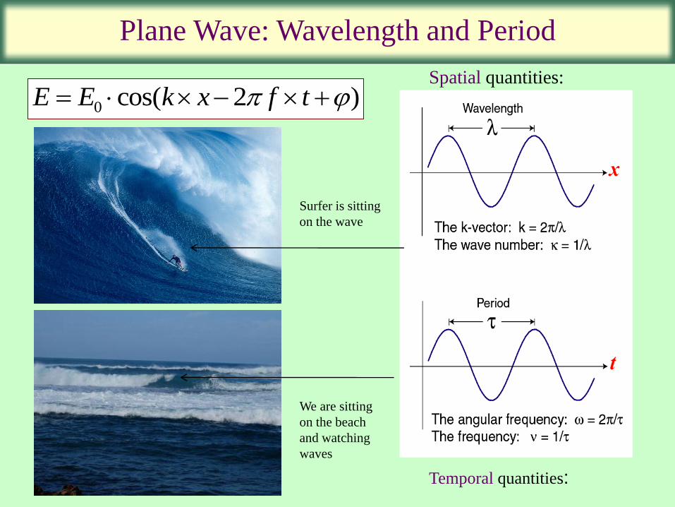
Plane Wave: Wavelength and Period
Spatial quantities:
Temporal quantities:
0 cos( 2 )E E k x f t
Surfer is sitting
on the wave
We are sitting
on the beach
and watching
waves

Numerical Aperture
Semi-aperture angle (): angle between
the normal ray and the furthest ray
entering the system.
Numerical Aperture =
18
NA=n(sin )
Light
cone
(n=refractive index)
NA can exceed 1.0 by using other immersion liquids including water
(1.333) or oil (1.51).
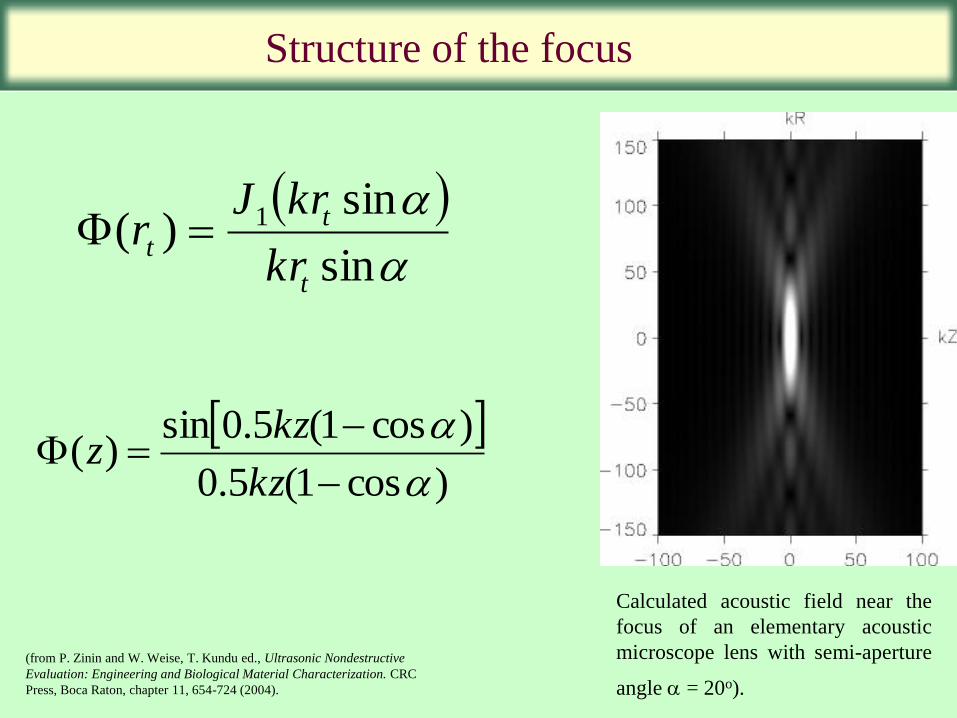
sin
sin)( 1
t
t
tkr
krJr
)cos1(5.0
)cos1(5.0sin)(
kz
kzz
Structure of the focus
Calculated acoustic field near the
focus of an elementary acoustic
microscope lens with semi-aperture
angle = 20o). (from P. Zinin and W. Weise, T. Kundu ed., Ultrasonic Nondestructive
Evaluation: Engineering and Biological Material Characterization. CRC
Press, Boca Raton, chapter 11, 654-724 (2004).
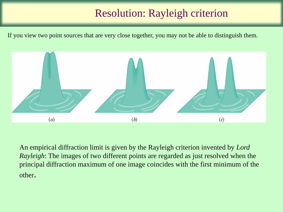
Resolution: Rayleigh criterion
If you view two point sources that are very close together, you may not be able to distinguish them.
An empirical diffraction limit is given by the Rayleigh criterion invented by Lord
Rayleigh: The images of two different points are regarded as just resolved when the
principal diffraction maximum of one image coincides with the first minimum of the
other.
l
cos1 axialz
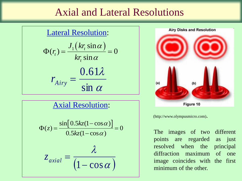
Axial and Lateral Resolutions
l
sin
61.0Airyr
(http://www.olympusmicro.com).
The images of two different
points are regarded as just
resolved when the principal
diffraction maximum of one
image coincides with the first
minimum of the other.
1 sin( ) 0
sin
t
t
t
J krr
kr
Lateral Resolution:
Axial Resolution:
sin 0.5 (1 cos )( ) 0
0.5 (1 cos )
kzz
kz
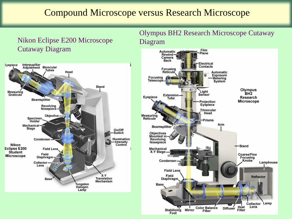
Compound Microscope versus Research Microscope
Nikon Eclipse E200 Microscope
Cutaway Diagram
Olympus BH2 Research Microscope Cutaway
Diagram
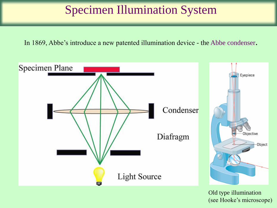
Specimen Illumination System
In 1869, Abbe’s introduce a new patented illumination device - the Abbe condenser.
Old type illumination
(see Hooke’s microscope)
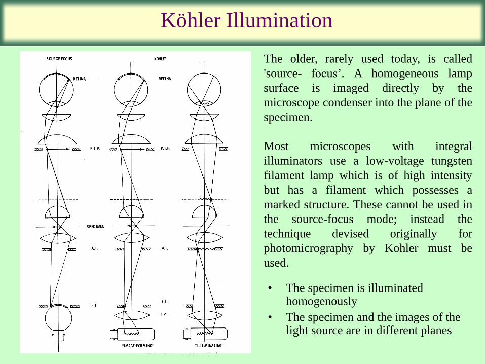
Köhler Illumination
The older, rarely used today, is called
'source- focus’. A homogeneous lamp
surface is imaged directly by the
microscope condenser into the plane of the
specimen.
Most microscopes with integral
illuminators use a low-voltage tungsten
filament lamp which is of high intensity
but has a filament which possesses a
marked structure. These cannot be used in
the source-focus mode; instead the
technique devised originally for
photomicrography by Kohler must be
used.
• The specimen is illuminated homogenously
• The specimen and the images of the light source are in different planes
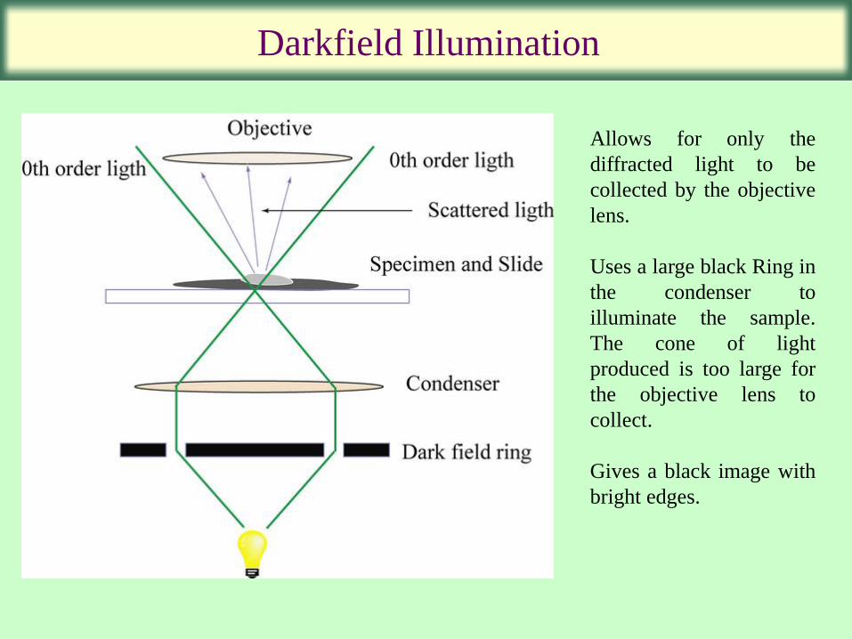
Darkfield Illumination
Allows for only the
diffracted light to be
collected by the objective
lens.
Uses a large black Ring in
the condenser to
illuminate the sample.
The cone of light
produced is too large for
the objective lens to
collect.
Gives a black image with
bright edges.
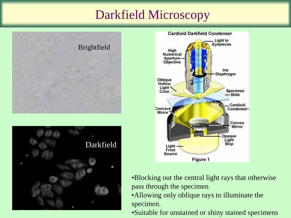
Darkfield Microscopy
Brightfield
Darkfield
•Blocking out the central light rays that otherwise
pass through the specimen
•Allowing only oblique rays to illuminate the
specimen.
•Suitable for unstained or shiny stained specimens
Home work
1. Introduce the concept of spherical waves and present mathematical
equation describing a spherical wave.
2. Simulate lateral and axial resolutions as a function of aperture angle.
3. Describe the difference between magnification and resolution.