optimisation methods for rotors of twin-screw compressors helpertz... · the class csegmentprofile...
TRANSCRIPT
Nr. 3
Optimisation Methods for Rotors of Twin-Screw Compressors
Prof. Dr.-Ing. K. Kauder, Dipl.-Ing. M. Helpertz
FG Fluidenergiemaschinen, Universität Dortmund
Prof. Dr. rer. nat. B. Reusch, Dipl.-Inform. S. Berlik
Informatik Lehrstuhl I, Universität Dortmund
The Deutsche Forschungsgemeinschaft (DFG) financially supported this project
Abstract
A general reflection concerning the modelling of machines using several abstraction levels is presented. For an exemplary twin-screw compressor this results in a representation of the rotor profile by means of bézier segments. Beginning with arbitrary initial profiles, evolution strategies show their basic suitability by optimising single criteria such as the scoop area. Depending on the initial form, only local optima are found. Using an extended offspring generation scheme to modify the optimisation process, search behaviour can be improved.
1 Introduction
Designing any type of machine leads inevitably to the question of the "optimised" construction parameters. As a rule this can be estimated by the performance with regard to user requirements. The main problem is to define acceptable performance and evaluate a possible solution with low calculation complexity. Usually there are many different criteria to be considered. Thus an appropriate optimisation method has to be able to either represent different criteria within one utility function or to treat several criteria in parallelly. If furthermore the optimisation is supposed to run partially or completely automatically, there arises the problem to derive an adequate simulation model.
This problem will be investigated below using a dry running twin-screw compressor as a representive example. It is intended to show how to evolve a computer-based model starting with user requirements and passing through several levels of abstraction.
The emphasis of the article is an investigation into the optimisation of the two-dimensional rotor profile, which possesses high priority for the twin-screw compressor's functionality. The representation of the profile by parametrical spline functions serves as a new approach compared with the traditional method of combining fixed curve types manually. Finally exemplary optimisations of simple
1

Nr. 3
criteria reveal the aptitude and behaviour of evolutionary strategies as a tool for finding optimised solutions.
2 State of the Art
2.1 Twin-Screw Plants
The design of twin-screw plants and of the twin-screw machine's geometry depend largely upon the planned operational conditions as well as upon the type of gas applied. Usually the design process starts with the calculation of the thermodynamic cycle. Thereafter further calculations are done, based on available geometries and standard machines. Procurable models determine the number of stages, the plant set up and rotational speeds.
The optimisation of a single compressor stage is mainly characterised by the determination of geometric data like the number of lobes, the flank form of the rotor profile, the rotor length, the wrap angle, the position of the guiding edges as well as by operational data such as the rotational speed and - where applicable - the amount of liquid injection. The development of the profile is generally separate from the design of the other construction parameters.
For the determination of these data it is possible to use geometric calculations /1 - 4/ such as the calculation of clearance areas, chamber volumes etc. or more detailed calculations involving FE-Methods in order to analyse both thermodynamic and geometric effects /4 - 8/. In the case of industrial development it is common practise to include much empirical data into the design process of new twin-screw machines.
2.2 Flank Forms
Initially there is the construction of a suitable profile design of the rotors due to its significant influence on the machine's operational behaviour, thermodynamic and geometric properties and on the machining. The relevance of the cross-section results from the operational principle of twin-screw machines, which work without any contacting seals between their working chambers. Varying the flank form and varying the number of lobes influences the geometry and the position of the intermesh clearances, the volume of the working chambers and the utilisation of the construction volume.
Concerning the profile design, the company Svenska Rotor Maskiner succeeded in 1970 in developing a new asymmetrical profile instead of the common circle-arc profile, which led to an efficiency increase of 10% /1/. Buthmann /6/ shows that the
2

Nr. 3
polytropic efficiency1) can be increased by further modifications of the profile form from �pol = 0,856 to �pol = 0,915. Also in the recent past, further evidence of successful profile improvements can be found in literature like the development of the N-profile by Stosic /9/. These examples demonstrate the potential of fundamental geometry optimisations.
In the past the development of the cross section profile geometry was generally based on the combination of a few basic curve types. Typical applied curve types are lines, circle arcs, evolvents, parabolics, cycloids or equidistant curves to cycloids. Many of the investigated patents deal with improvements of the geometrical, thermodynamic or machining properties. Often the inventions are based on certain curve types or only modify existing profile types.
Due to the capability of modern computer systems, several attempts to convert the geometrical description of profiles to discrete points or parametrical curves have been made. This permits modifications of flank geometries in a more flexible and automated way, in order to meet specific operational demands. Examples can be taken from the literature about general problems of tooth design /10 - 15/.
This article investigates mainly how to use similar approaches for the optimisation of twin-screw rotors. Firstly the investigations are limited to planar rotor profiles. As a speciality it has to be mentioned that the construction of the flanks is provided to run non-interactively but completely automatically by means of a computer program. The only interactive procedure is to determine certain criteria and their corresponding weightings initially or to select suitable solutions from a set of optimised profiles after an optimisation procedure. Thus the user of such an optimisation program does not need any specific knowledge about meshing theory because it is already implemented.
2.3 Optimisations Methods
As an optimisation method an evolution strategy has been chosen. The term evolutionary algorithm (EA) is used to classify stochastic optimisation methods that simulate the process of natural evolution. The origins of EA can be traced back to the late 1950s and, since the 1970s several evolutionary methodologies have been proposed, mainly genetic algorithms, evolution strategies, and evolutionary programming /16, 17/. They all share the common conceptual base of simulating the
1)
���
f
fpol w
wη
with: wf specifical reversible delivery work � specifical dissipation
3

Nr. 3
evolution of individual structures via a process of selection and reproduction. New individuals are created using genetic operators such as mutation and crossover. The probability of survival of the newly generated solutions then depends on their fitness, i.e. how well they perform with respect to the given optimisation problem. What makes EAs so attractive from the optimisation point of view is that they do not make much in the way of mathematical demands on the optimisation model. They are 0-order methods, which means that all they need is an objective function to be evaluated - without any derivation. Further, they can handle non-linear problems, defined on discrete, continuous or mixed search spaces, unconstrained or constrained /18/.
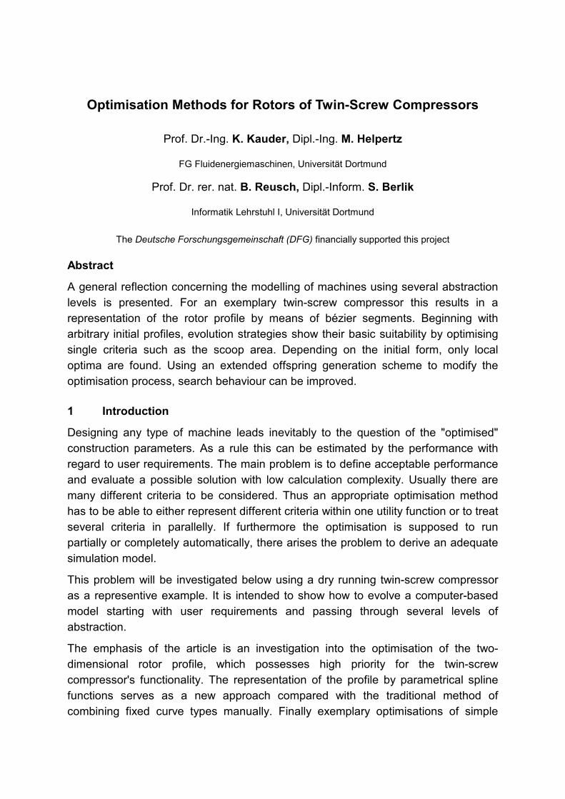
The class of the evolution strategies (ESs) has been selected, because they use real-valued vector representations, and are thus best suited to the given problem. Fig. 1 outlines a typical ES /19/.
t = 0;
initialise population P(t);
evaluate P(t);
until (done) {
t = t +1;
parent_selection P(t);
recombine P(t);
mutate P(t);
evaluate P(t);
survive P(t);
}
Fig. 1: The evolution strategy algorithm A common notation to characterise an ES has been introduced by Rechenberg /20/. He summarises the main strategy parameters in the form: (� , �), with � being the number of parents and � being the number of offspring, separated by the selection operator. The ‘,’ represents a strategy, where the parents of the following generation are only selected from the offspring of the current generation. Another commonly used strategy is the ‘+’ selection, where parents can survive and thus the parents of the following generation are selected from the offspring and parents of the current generation together.
2.4 Multiple Criteria Decision
Solving multi-objective scientific or engineering problems is in general a very difficult goal. One usually faces the difficulty of conflicting objectives and limited scope for
4
Nr. 3
decision making. As a result high dimensionality extensive computational resources are needed.
Whereas single-objective optimisation problems may have a unique optimal solution, multi-objective optimisation Problems (MOPs) usually present a possibly infinite set of solutions /21/. Optimisation problems involving multiple, conflicting objectives have in the past often been approached by aggregating the objectives into a scalar function and solving the resulting single-objective optimisation problem, whereas here the goal is to find a set of optimal trade-offs, the so-called Pareto-optimal set.
A multi-objective search space is partially ordered in the sense that two arbitrary solutions are related to each other in two possible ways: either one dominates the other or neither dominates /16/.
Definition 1: Let us consider, without loss of generality, a multi-objective optimisation problem with m decision variables (parameters) and n objectives:
YyyyXxxxwhere
xfxfxfyMinimize
n
m
n
��
��
��
),(),,(
))(,),(()(
1
1
1
�
�
�
�
�
�
���
eq. (1)
and where is called decision vector, parameter space, x� X y� objective vector, and objective space. A decision vector aY X�
� is said to dominate a decision vector (also written as ) if and only if X�b
�
ba�
��
)()(:},,1{
)()(:},,1{
bfafnj
bfafni
ii
ii�
�
�
�
�
�
���
���� eq. (2)
With this, nondominated and Pareto-optimal solutions can be defined:
Definition 2: Let be an arbitrary decision vector: Xa �
�
1. The decision vector is said to be nondominated regarding a set if and only if there is no vector in ' which dominates
a� XX �'X a� .
2. The decision vector a is Pareto-optimal if and only if a is nondominated regarding .
� �
X
Pareto-optimal decision vectors cannot be improved in connection with any objective without causing a degradation in at least one other objective; they represent in this context globally optimal solutions.
EAs have become established as the method for exploring the Pareto-optimal front in MOPs that are too complex to be solved by exact methods, like linear programming and gradient search /16/. The two main reasons for this are their ability to handle
5

Nr. 3
extremely large search spaces and the convenience to approximate the whole Pareto-optimal front in one single run.
3 Abstraction Levels of the Modelling Procedure
Because of the complexity of general construction problems it is not possible to present a consistent method for the abstraction of any desired machine or component. Thus the method briefly described below has to be seen as a suggestion, which would need to be adapted to other problems analogously. More detailed publications concerning this topic are intended.
3.1 Function
Starting with maximum detailed knowledge of the machine's functionality and its physical mode of operation, it is necessary to determine first which are the most important user demands (inputs) and the most important construction parameters (outputs). Analysing the interdependencies between input und output parameters helps to obtain an order of priorities for the construction parameters and to decouple groups of parameters. This makes it possible to simplify the optimisation problem into sub problems that can be optimised separately.
From an abstract point of view the user of a twin-screw compressor requires a thermodynamic flow, which leads to a modification of the fluid's energy content, mainly its pressure energy. Therefore an order of priorities for the inputs can be determined. They are completely different from the machine's design parameters, table 1.
User Demands (Inputs), Sorted by Decreasing Priority
Construction Parameters (Outputs), Unsorted
Pressure ratio Volume flow Fluid type Inlet pressure Inlet temperature Purchase and operational expenses
Rotational speed Number of lobes Tooth pitch or axis distance Profile form Length / diameter ratio Wrap angle Geometry and position of the guiding edges
Table 1: Results of a simplified functional analysis In order to ascertain priorities for the outputs it is useful to estimate the effect of varying a single output on the performance of the input requirements. This can be realised within a weighted matrix, containing all possible and evaluated interdependencies. Weighting them according to the input priorities and adding together the weighted interdependencies of each output parameter leads to an order of priorities for all outputs. It is inevitable that an evaluation of the interdependencies
6

Nr. 3
is influenced by subjective ratings or has to be roughly estimated. In this case the matrix has to be revised when more details are revealed.
Applied to a twin-screw compressor the above method reveals two main results: o Due to the mandatory requirement of developing suitable working chambers
and due to their substantial influence on thermodynamical and mechanical properties, the geometric data of the rotor profile becomes the most important set of parameters.
o In a first step it seems logical to optimise the two-dimensional profile independent of three-dimensional data such as rotor length and wrap angle.
3.2 Key Figures
Once a solution is determined, it is necessary to evaluate its performance, which results from its physical properties. Usually technical optimisation problems are too complex to be solved analytically. Therefore iterative working methods are inevitable, but they have to evaluate a huge amount of different solutions on their way to an optimum. As a consequence it is not possible to simulate the solution's performance exactly, but instead to find simple criteria with low calculation costs, which correspond with physical tendencies. Usually this leads to a focus on criteria, which can be calculated from geometrical data. Criterion Name Physical Meaning Definition K1 Scoop area per
male rotor rotation
As this area delivers the fluid it characterises the geometrical exploitation of the construction size. FE
MAFEMA1 z
z A AK ���
eq. (3)K2 Referred polar
moment of inertia
K2 characterises the resistance to deflections for a constant rotor length, wrap angle and pressure load. In order to consider the worst case, the minimum male and female values are selected.
���
����
��
FE
FEp,
MA
MAp,2 D
I;
DI
min K
eq. (4)
K3 Blow hole height The distance between the contact line and the cusp represents one dimension of the blow hole, which influences the internal leakage rate and thus the thermodynamic performance
B3 h K � eq. (5)
Table 2: Exemplary criteria for profile optimisation Symbols: A Tooth space area of all teeth, z Number of lobes, I Moment of inertia D Outer diameter h Height Indices: MA Male rotor FE Female rotor B Blow hole p Polar
7
Nr. 3
Evaluation criteria of twin-screw compressors can be divided into several main topics:
o geometry, o mechanics, o thermodynamics, o machining.
Corresponding key figures can be found in /1, 2, 4, 22/ or have to be determined by the user. A useful method is the �-theorem /23/, which converts single key figures into dimensionless key figures by analysing their units.
In order to optimise a two-dimensional rotor profile, three simple exemplary criteria for a constant axis distance were chosen /24/, table 2.
These three criteria are in fact incomplete for the purpose of obtaining suitable profiles, but they allow the basic properties of the optimisation method to be tested. Currently more than 10 criteria in all have been implemented. Future investigations will focus on the implementation of additional criteria and their suitability for a competitive optimisation.
Using several criteria the problem of determining their priority occurs once again. Consequently it is necessary to estimate their influence on user demands in the same way as the influence of the construction parameters. This leads to the following priorities:
o scoop area, o referred polar moment of inertia, o blow hole height.
This article focuses on the optimisation of single criteria, but multiple criteria optimisations are planned for the future.
3.3 Geometry
When a machine is modelled, it may be necessary to depict the geometry of mechanical components. It is worth investigating the possibilities of a geometrical data processing and to define the corresponding geometrical requirements. Geometrical abstraction exercises an important influence on the quality of the solution, the dimension of the mathematical search space and on the calculation costs in general. /25 - 27/ offer helpful basics concerning this topic.
Returning to the sample machine, it is necessary to find a mathematical description for the rotors of twin-screw compressors, starting with the two-dimensional profiles of the male and the female rotor.
8

Nr. 3
In the first instance there are three self-evident possibilities, which are shown in table 3, with their varying characteristics.
Owing to the intention of an automated optimisation, the spline method was selected. The next decision concerns the spline type. In order to simplify the mathematical treatment, concerning the calculation of different geometrical data and the verification of some boundary conditions, the choice was made for a combination of parametrical quadratic bézier segments, fig. 2, which can also be converted into a quadratic b-spline. The starting point and the end point are part of the curve. The connection of the boundary points and the control point represents the tangent directions at the beginning and the end of the curve respectively. For initial investigations it was accepted that the approximation behaviour of this spline type might be inaccurate for certain meshing situations of rotor profiles. On the other hand the treatment and certain geometrical calculations are less complex with that type of curve. More details about this topic are planned in future publications.
Geometrical Approach Advantage Disadvantage Combinations of different analytical curve sections
o The possibility of the exact reproduction of traditional profiles
o Applicability of basic meshing conditions
o Existence of analytical solutions for the conjugate flanks for certain curve types
o Low dimension of the search space
o Complication of automated computing due to the treatment of different curve types
o Partially higher calculation costs for geometrical data such as curvature, normal vectors etc. depending on the curve type
A set of discrete flank points o Independence from certain curve types
o No applicability of the basic meshing conditions
o No calculation of certain geometric data such as curvature, normal vectors etc.
o High dimension of the search space
A spline with a consistent section type
o Applicability of basic meshing conditions
o Low dimension of the search space
o No distinction between different curve types
o Partially adaptable standard solutions for geometrical problems in the literature
o Different approximation quality of analytical curve types
o Higher calculation costs when simple curve types are approximated
Table 3: Properties of different geometrical approaches for rotor profiles
9

Nr. 3
P0
P1
P2
Fig. 2: Bézier segment (curve) and its control polygon (lines) for the generation of profile
flanks P0 Starting point P1 Control point P2 End point
3.4 Data structure
For an automated optimisation it is necessary to provide a data structure, which lives up to the demands of a machine-specific representation on the one hand, and which guarantees quick access to the optimisation methods on the other hand.
Because of the complexity of the problem an object-orientated programming language is an essential requirement. This provides a hierarchical data structure, where deriving data from basic classes and adding specific properties can lead to the construction of more complex data classes.
The implementation of the profile optimisation is realised by C++ and has a modular structure in order to offer specific libraries. The system can be divided into the sections below:
o geometrical representations, o profile representation and calculation, o optimisation, o visualisation, o files, o common functions.
The design of the data classes has an important influence on the readability of the source code and the system's ease of maintenance. In order to obtain a proper class design, not only is knowledge of the programming language needed but also a lot of experience concerning the development of logical structures /28/. Fig. 3 gives an example of the structure of the profile class, which was applied for the optimisations
10

Nr. 3
in chapter 4.3. It uses classes of different sections such as geometry, profile and optimisation.
list
i : element
TSegmentList
i : element
CSegmentProfile
CSegmentProfileOpt
CPoint
CPoint2dother Points
CSegment
other Segments CBezierSegment
2
1
1
1
<<bind>> <TYPE*>
<<bind>> <CSegment>
Fig. 3: Simplified data structure for the optimisation of twin-screw profiles
CPoint: Abstract class for the representation of points CPoint2d: Class for two-dimensional points with both Cartesian and
polar coordinates CSegment: Class for the representation of segments with a starting
and an end point CBezierSegment: Class for the representation of bézier segments with a
starting, a control and an end point list: List of a standard template library TSegmentList: List of pointers to segment elements providing geometrical
functions CSegmentProfile: Class with basic profile data and basic segment types CSegmentProfileOpt: Class with additional data and functions for an
optimisation with bézier segments
4 Optimisation
4.1 Optimisation Method
During optimisation the generation of feasible offspring turns out to be very difficult. The classical (�����)-ES /29/ does not cope with the given constraints. During an initial phase no problems occur and it is possible to create all the � desired offspring. After a while more and more descendants of the population are not feasible any more due
11

Nr. 3
to one or more of the mechanical constraints. This leads to a point where none of the children falls into the feasible region thus terminating the optimisation.
To overcome this problem two techniques have been tested, as a penalty function method /18, 30/ the global competitive ranking /31/ and an extended offspring generation scheme. The first technique aims to handle both feasible and infeasible offspring whereas the second one tries to keep the offspring valid.
4.1.1 Global Competitive Ranking
The purpose of this method is to use information from both feasible and infeasible individuals. In this scheme, an individual i is ranked by comparing it against all other members of the population. This has to be done for both the objective and penalty functions. Afterwards a unified ranking is set up. For this it is essential to strike the right balance between objective and penalty functions.
The drawback of this approach is that for the given problem a population that has left the feasible region is never able to re-enter it. Unfortunately in every trial the infeasible region was entered after a few hundred generations.
4.1.2 Extended Offspring Generation Scheme
To be able to provide enough feasible individuals in the population, a new generation scheme has been deployed. In contrast to standard ES more attempts per child to create a valid offspring are undertaken. The number of attempts can be chosen by the variable . attMax
The procedure then works in the following way: A first attempt to generate a feasible offspring is carried out. If this is successful the procedure turns toward the next child. In case of failure the remaining attempts are carried out. Again, if an attempt is successful, the next child will be processed. If it is not possible to create a valid child within attempts, the next step depends on the number of the actual offspring. If the child is one of the first �����, then it is left invalid and will die out in the next generation. If it is instead one of the last �, it has to be guaranteed that there will be at least � valid offspring to build up the next generation. So if the number of offspring remaining to be generated is less then the number of the parents minus the actually valid offspring, then the current child has to be replaced by the corresponding parent. In other words parent �
attMax i
��i�� has to be selected if ofsi ��� �� with being the number of actually feasible offspring. The whole algorithm is shown in fig. 4.
ofs
With this generation scheme a test has been done to see how many attempts are reasonable for the given problem. The parameters were chosen as follows: (3,10) - ES, 2500 generations, each 5 runs. 500,200,100,50,20,10,1�attMax
12

Nr. 3
;0�ofs
for i to 1� � { ;0�att do { );( igenerate �
;1�� attatt } while ( is ) attMaxattfeasiblenot i �&)(__ �
if ( is ) )(_ ifeasible �
;1�� ofsofs else if ( ofsi ��� �� ) {
� ;1��� ii ��
} }
Fig. 4: The Extended Offspring Generation Scheme with : Parents �
� : Offspring : Feasible offspring ofs
att : Attempts : Maximum attempts attMax
attMax Averaged valid offspring per generation
1 0.93
10 2.35
20 2.13
50 3.65
100 4.17
200 4.97
500 6.34 Table 4: Averaged number of valid offspring per generation for different numbers of
attempts What can be thought on looking at table 4 is that attMax has to lie between 20 and 50 if there are going to be on average enough valid offspring to build up the next generation. Further, up to a value of 200 for , not even half the offspring are feasible on average. But that is only half the truth, as can be seen in fig. 5 and fig. 6 respectively.
attMax
The vital point is that it is relatively easy to create offspring during the initial phase even with few attempts, whereas later fewer and fewer feasible children are generated. So the mean value over all generations is higher than the mean value at the end of the optimisation, and thus the stated value might be not very meaningful.
13
Nr. 3
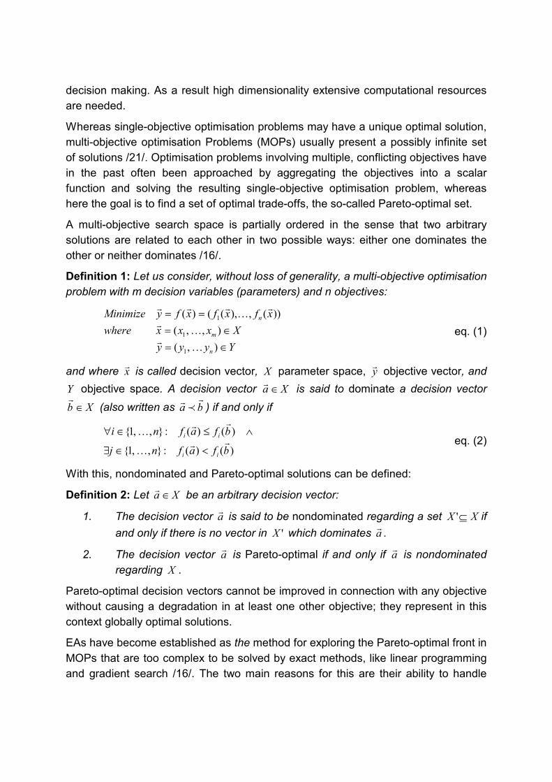
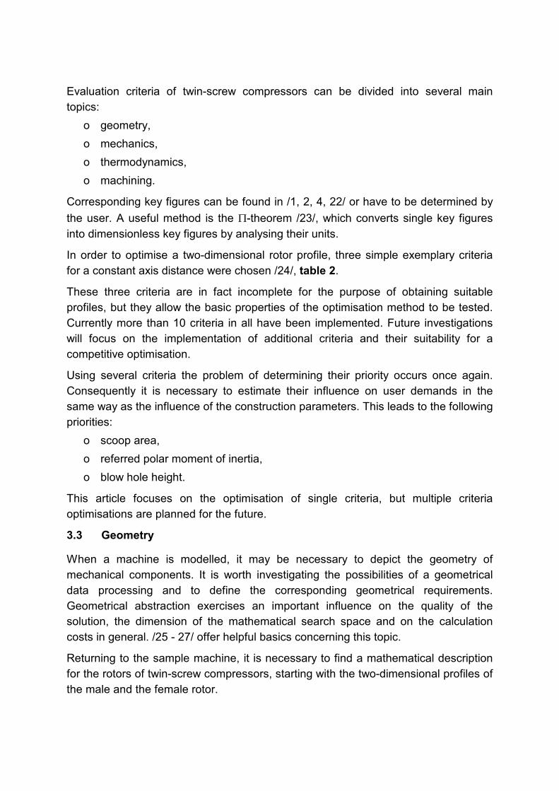
Another observation is that after 500 attempts the optimisation succeeds in recovering, which means that it is possible to come from few valid offspring back again to a larger population.
To sum up, the extended offspring generation scheme is an instrument to provide the ES with the required number of offspring. It has an impact on the selection scheme by modifying it to span the whole range from a pure comma strategy to a pure plus strategy, covering all shades between these two extremes and doing this dynamically.
0
1
2
3
4
5
6
1 201 401 601 801 1001 1201 1401 1601 1801 2001 2201 2401
Generations
Ave
rage
dva
lidof
fspr
ing
Fig. 5: The development of the offspring for attMax = 1.
0
2
4
6
8
10
12
1 201 401 601 801 1001 1201 1401 1601 1801 2001 2201 2401
Generations
Ave
rage
dva
lidof
fspr
ing
Fig. 6: The development of the offspring for attMax = 500.
14

Nr. 3
4.1.3 Optimisation Parameter
The optimisation strategy can be configured with several parameters. The core parameters are:
o �: the number of the parents in the population
o �: the number of the offspring to be created o selection operator:
determines whether parents can survive or not (chapter 2.3) o the number of generations
If recombination (i.e. sexual reproduction) is desired, it can be controlled by:
o �: the number of parents that are used to generate an offspring o the mixing scheme: discrete / intermediary
For the mutation of the segments radii, angles, and gradients of points have to be processed. For each, values have to be provided for:
o lower limit of the mutation step size o upper limit of the mutation step size o initial mutation step size
As an asymmetrical mutation scheme has been implemented /32/, apart from this, for each mutation (i.e. for the radii, the angles, and the gradients) there also have to be given:
o lower limit of the asymmetry o upper limit of the asymmetry o initial value for the asymmetry
Last, for the extended creation scheme: o attMax:
states how many attempts are carried out to create a valid offspring (chapter 4.1.2)
4.2 Automated Geometry Synthesis
The class CSegmentProfile represents the two dimensional profile of one rotor for twin-screw compressors, containing the flank form of one lobe and additional data such as the number of lobes, the root, the crown and the roll circle. It can contain different segment types, but for the optimisation bézier segments were used exclusively. Furthermore the tangents of adjacent segments are coincident at their
15
Nr. 3
common boundary point. Therefore a variety of different flank forms can be produced with a relatively low number of segments.
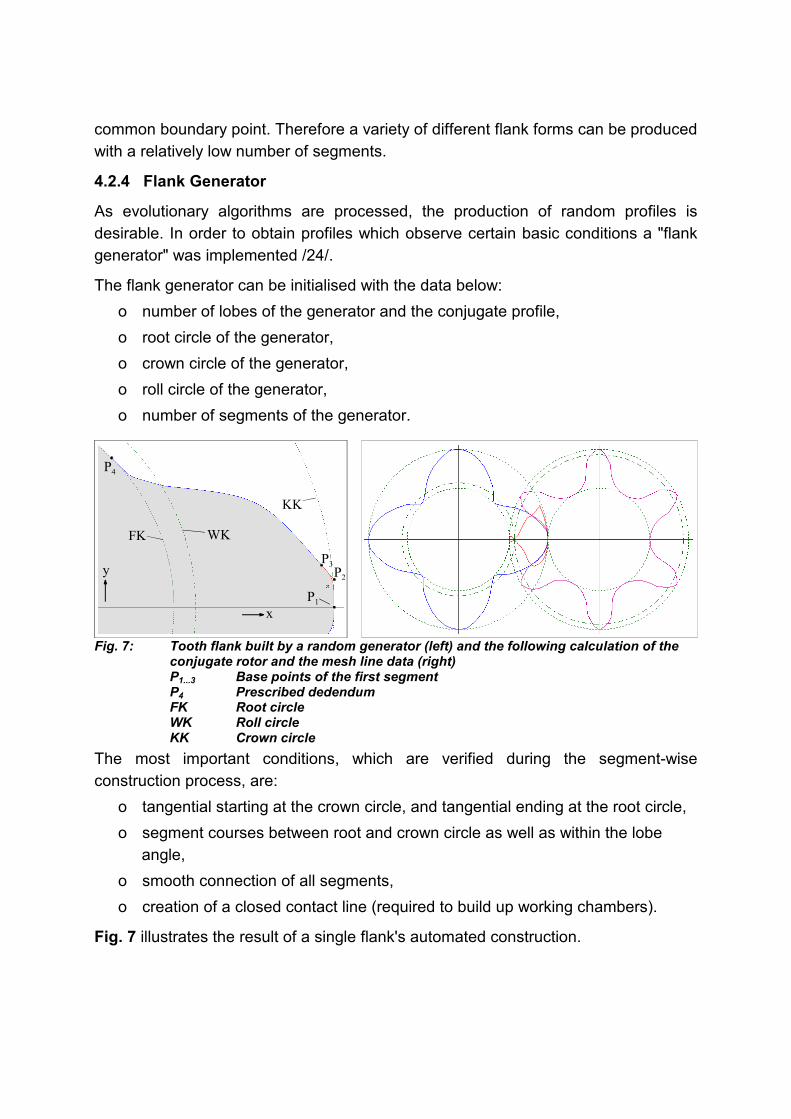
4.2.4 Flank Generator
As evolutionary algorithms are processed, the production of random profiles is desirable. In order to obtain profiles which observe certain basic conditions a "flank generator" was implemented /24/.
The flank generator can be initialised with the data below: o number of lobes of the generator and the conjugate profile, o root circle of the generator, o crown circle of the generator, o roll circle of the generator, o number of segments of the generator.
P1
P4
P3P2
FK WK
KK
y
x
Fig. 7: Tooth flank built by a random generator (left) and the following calculation of the conjugate rotor and the mesh line data (right) P1...3 Base points of the first segment P4 Prescribed dedendum FK Root circle WK Roll circle KK Crown circle
The most important conditions, which are verified during the segment-wise construction process, are:
o tangential starting at the crown circle, and tangential ending at the root circle, o segment courses between root and crown circle as well as within the lobe
angle, o smooth connection of all segments, o creation of a closed contact line (required to build up working chambers).
Fig. 7 illustrates the result of a single flank's automated construction.
16

Nr. 3
4.2.5 Flank Manipulator
Since an initial flank form is produced, it is necessary to manipulate its geometry randomly and to filter out better solutions according to the above optimisation algorithm, chapter 4.1.
Three manipulation operators have been deployed to change the profile geometry (e.g. with reference to point P3 in fig. 7):
o variation of a base point's polar radius, o variation of a base point's polar angle, o variation of a base point's tangential direction.
After each manipulation all boundary conditions have to be checked, and non-valid profiles are excluded out or the evaluation is corrected by means of penalty functions.
4.3 Exemplary Profile Optimisations
Former investigations focussed on optimisation of the single criteria in table 2 /24/. Fig. 8 summarises the main results on their way from the corresponding initial geometry to the improved modifications. Since only single criteria where optimised the results are not competitive for realistic twin-screw compressors, which have to take into account several criteria simultaneously (scoop area, blow hole area, length of the contact line, small deflections etc).
Current research work concentrates on the influence of the initial form on the result and on the reproducibility of the method. Depending on the criterion and the boundary conditions, it is quite likely to get bagged down in local optima. It is part of this examination to start with the same geometry several times on the one hand and to start with explicitly different geometries on the other hand. After the optimisation process the differences between the results are analysed comparatively .
The investigations are not yet finished, so only a few results can be presented at present. Four initial profiles have been realised as shown in fig. 9, with radically different specifications. All profiles fulfil the basic meshing conditions and have a closed contact line. Every form was applied to the scoop area, criterion K1.
For profiles a), b), and c) only preliminary results are available, because of short optimisation runs due to time limitations. With profile d) extended tests have been done, because it seems to be the most awkward profile.
Several test runs with rotor a) have been undertaken, all leading to more or less the same result. At the end there was always a quadrate-like shape with rounded edges, fig. 9. Some constraints prevent the plain sides from caving in. Further investigations have to be done to be able to ascertain the reasons for this behaviour.
17

Nr. 3
a
b
c
2
1
Fig. 8: Comparison of initial profiles (hollow) and optimised profiles (shaded grey) for
different criteria and fixed axis distance Left: Male rotor Right: Female rotor a) Maximised scoop area (root and crown circle not fixed) b) Maximised referred polar moment of inertia (root and crown
circle not fixed) c) Minimised blow hole height with mesh line of the optimised
profile (1) and of the initial profile (2) (root and crown circle fixed)
18
Nr. 3
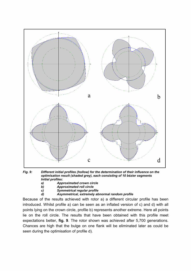
Fig. 9: Different initial profiles (hollow) for the determination of their influence on the
optimisation result (shaded grey), each consisting of 10 bézier segments Initial profiles:
a) Approximated crown circle b) Approximated roll circle c) Symmetrical regular profile d) Asymmetrical, extremely abnormal random profile Because of the results achieved with rotor a) a different circular profile has been introduced. Whilst profile a) can be seen as an inflated version of c) and d) with all points lying on the crown circle, profile b) represents another extreme. Here all points lie on the roll circle. The results that have been obtained with this profile meet expectations better, fig. 9. The rotor shown was achieved after 5,700 generations. Chances are high that the bulge on one flank will be eliminated later as could be seen during the optimisation of profile d).
19
Nr. 3
The optimisation of profile c) progressed in an unexpected way. It was just not the easiest case. On the contrary, this profile was the one where the feasibility of the offspring turned out to be the hardest problem. Several runs led to the result that after a few thousand generations no valid offspring could be generated. The reasons for this are not yet known. Nevertheless the optimisation is tending to advance in the right direction, as shown in fig. 9 for a rotor of generation 1,500.
The most interesting challenge could be seen in optimising profile d). It was very interesting to check if the optimisation would cope with this extremely abnormal profile. After 20,000 generations a rotor had been generated that has a scoop area of 8.1 · 10-3 m2, thus being comparable to the most successful one from former trials, fig. 8. What also emerged is that the optimisation is capable of straightening out bulges. All this tends to confirm that the chosen algorithms are suitable for solving the given problem.
5 Perspective
The optimisation procedure presented here has demonstrated its suitability in principle, but does not yet lead to competitive profiles. Furthermore its properties on the way to an optimum have to be investigated more intensively.
Concerning the optimisation method, the points below are planned to be investigated: o influence of the optimising parameters, o implementation of methods for multi-objective optimisation, o more experiments on reproducibility and on initial forms are needed along with
other criteria such as the blow hole width and the referred moment of inertia.
In order to obtain more realistic profiles it is projected to o process further criteria, which are already implemented but not yet tested, o vary more profile parameters such as the number of lobes and the number of
segments and to o extend the method to the three dimensional design of rotors including rotor
length and wrap angle.
Finally a sensitivity analysis will reveal the influence of single parameters and the possibility of decoupling a two dimensional from a three dimensional rotor-design optimisation.
6 References /1/ Rinder, L. Schraubenverdichter. Springer-Verlag, Berlin/Heidelberg/New York, 1979
/2/ Schüler, R. Entwicklung von Schraubenmaschinen-Rotoren. Ein Beitrag zur Optimierung von Schraubenmaschinen.Dissertation, Universität Dortmund, 1984
20
Nr. 3
/3/ Rau, B. Ein Beitrag zur Auslegung trockenlaufender Schraubenkompressoren. Dissertation, Universität Dortmund, 1994
/4/ Dreifert, Th. Thermisches Verhalten der Rotoren von Schraubenkompressoren. Dissertation, Universität Dortmund, 1996
/5/ Stosic, N., Hanjalic, K. Development and optimization of screw machines with a simulation model - Part 2: thermodynamic performance simulation and design optimization.In: Transactions of the ASME, Series I. Journal of Fluids Engineering, Band 119, Heft 3, Seite 664-670, 1997
/6/ Buthmann, P. Rechnergestützte Schraubenverdichterprofilentwicklung und -rotorauslegung unter Berücksichtigung der betriebsbedingten Verformungen. Dissertation, Ruhruniversität Bochum, 1985
/7/ Rofall, K. Ein Beitrag zur Verifizierung eines Simulationssystems für trockenlaufende Schraubenkompressoren. Dissertation, Univerität Dortmund, VDI Fortschrittberichte Reihe 1, Nr. 299, VDI-Verlag, Düsseldorf, 1998
/8/ Kauder, K., von Unwerth, Th. Die Heißgasschraubenmaschine. Simulationsgestützte Auslegung – Teil 3. In: Schraubenmaschinen, Forschungsberichte des Fachgebietes Fluidenergiemaschinen Nr. 6, ISSN 0945-1870, S. 70-84, Universität Dortmund, 1998
/9/ Stosic, N., Hanjalic, K. Development and optimization of screw machines with a simulation model - Part 1: profile generation.In: Transactions of the ASME, Series I. Journal of Fluids Engineering, Band 119, Heft 3, Seite 659-663, 1997
/10/ Esser, H. J. Entwicklung von Algorithmen zur rechnerunterstützten Konstruktion von Verzahnungen beliebiger Flankenformen. Dissertation, RWTH Aachen, Fotodruck Mainz GmbH, Aachen, 1985
/11/ Escher, Ch. Simulation und Optimierung der Erzeugung von Zahnflankenmodifikationen an Zylinderrädern. Dissertation, RWTH Aachen, Fakultät für Maschinenwesen, Kartographie und Druck Peter List, Aachen, 1999
/12/ Schwuchow, D. Sonderverzahnungen für Zahnradpumpen mit minimaler Volumenstrompulsation.Dissertation, Universität Stuttgart, Berichte aus dem Institut für Maschinenelemente, Bericht Nr. 64, Stuttgart, 1996
/13/ Köchling, M. Beitrag zur Auslegung von geradverzahnten Stirnrädern mit beliebiger Flankenform. Dissertation, Universität Stuttgart, Berichte aus dem Institut für Maschinenelemente, Bericht Nr. 52, Stuttgart, 1994
/14/ Roth, K. Evolventenverzahnungen mit extremen Eigenschaften. Teil IV: Profilsteigungsfunktion zur Synthese beliebiger Zahnflankenformen. Antriebstechnik, Band 36, Nr. 7, S. 53-58, 1997
/15/ Schekulin, K. GEAROS-Verfahren - Verzahnungsoptimierung durch rechnerunterstützte Eingriffssimulation. VDI-Z, Band 123, Nr. 22, S. 925-927, 1981
/16/ Zitzler, E., Deb, K., Thiele, L. Comparison of Multiobjective Evolutionary Algorithms: Empirical Results, Evolutionary Computation, 8(2), pp. 173-195, 2000
/17/ Bäck, T., Hammel, U., Schwefel, H.-P. Evolutionary computation: Comments on the history and current state. IEEE Transactions on Evolutionary Computation, vol. 1, no. 1, pp. 3-17, 1997.
21

Nr. 3
/18/ Michalewicz, Z., Schoenauer, M. Evolutionary algorithms for constrained parameter optimization problems. Evolutionary Computation, vol. 4, no. 1, pp. 1-32, 1996.
/19/ Spears, W.M., DeJong, K.A., Bäck, T., Fogel, D.B., de Garis, H. An Overview on Evolutionary Computation, Proceedings of European Conference on Machine Learning, Vienna, Austria, April 1993, Lecture Notes in Artificial Intelligence 667, Springer Verlag, Berlin Heidelber, pp. 442-459, 1993
/20/ Rechenberg, I. Evolutionsstrategie `94, frommann-holzboog Verlag, 1994
/21/ Van Veldhuizen, D. A., Lamont, G. B. Multiobjective evolutionary algorithm research: A history and analysis, Technical Report TR-98-03, Department of Electrical and Computer Engineering, Graduate School of Engineering, Air Force Institute of Technology, Wright-Patterson AFB, Ohio, December 1998
/22/ Weckes, N. Ein Beitrag zur Optimierung geometrischer und thermodynamischer Kenngrößen von Schraubenladern.Dissertation, Universität Dortmund, 1994
/23/ Buckingham, E. On physically similar systems; illustrations of the use of dimensional equations, In: The Physical Review, Vol. IV, Series II, pp. 345-376, Lancaster, PA. and Ithaca, N.Y., 1914
/24/ Kauder, K., Reusch, B., Berlik, S., Helpertz, M. Automatisierte Optimierung der Geometrie von Schraubenrotoren, Teil 1. In: Schraubenmaschinen, Forschungsberichte des FG Fluidenergiemaschinen Nr. 9, S. 27-46, ISSN 0945-1870, Universität Dortmund, 2001
/25/ Hoschek, J., Lasser, D. Grundlagen der geometrischen Datenverarbeitung, 2. Auflage, ISBN 3-519-12962-0, B. G. Teubner, Stuttgart, 1992
/26/ Piegl, L., Tiller, W. The NURBS book. ISBN 3-540-55069-0, Springer-Verlag, Berlin, Heidelberg, New York, 1995
/27/ Dierckx, P. Curve and Surface Fitting with Splines. Monographs on Numerical Analysis, Oxford Science Publications, ISBN 0-19-853441-8, Oxford, New York, Tokyo, 1993
/28/ Oestereich, B. Objektorientierte Softwarenentwicklung. Analyse und Design mit der Unified Modeling Language, 4. Auflage, ISBN 3-486-24787-5, R. Oldenbourg Verlag, München, Wien, 1998
/29/ Schwefel, H.-P. Evolution and Optimum Seeking, Wiley Interscience, New York, 1995
/30/ Kim, J.H., Myung, H. Evolutionary Programming Techniques for Constrained Optimization Problems, IEEE Transactions on Evolutionary Computation, vol. 1, no. 2, pp. 129-140, July 1997
/31/ Runarsson, T.P., Yao, X. Chapter 4. Constrained Evolutionary Optimization: The penalty function approach. Evolutionary Optimization. (Editors R. Sarker, M. Mohammadian and X. Yao) Kluwer Academic Publishers, USA, pp. 87-113, 2002
/32/ Hildebrand, L. Asymmetrische Evolutionsstrategien, 2001, PhD Thesis, Universität Dortmund, Computer Science
22