optimising the scale of a wind farm · pdf fileoptimising the scale of a wind farm development...
TRANSCRIPT
OPTIMISING THE SCALE OF A WIND FARM DEVELOPMENT AT THE WEAK EXTREMITY OF A RURAL NETWORK
RAY W BROWN ROGER PATERSON
Meridian Energy Ltd PowerNet Ltd
New Zealand New Zealand
SUMMARY
Meridian Energy Ltd (MEL) secured access to land that has the potential to site a productive
200 MW wind farm development. The site is located close to a single circuit 66 kV line at the
remote extremity of a complex rural 66 kV and 33 kV network managed by PowerNet Ltd
(the DNO), that is 75 km away from the 33 kV TSO GXP. Power quality requirements for the
wind farm are relatively stringent. The development was particularly challenging from a
number of transmission integration perspectives, due to the large size of the potential wind
farm compared to the weak transmission network. This paper describes the wind farm sizing
optimisation process focusing on the sub-transmission system technical integration challenges
and solutions.
The final scale of the development is a 58 MW wind farm consisting of 29 Doubly Fed
Induction Generator Wind Turbine Generators (WTGs). The wind farm was commissioned in
June 2007.
Following the optimisation process, final power system arrangements for the operation of the
wind farm include:
1) Robust WTGs with some low voltage ride through capability. These also assist to
control network voltages.
2) A wind farm STATCON improves the ability of the wind farm to ride through
transient power system faults and stabilises the power system. The STATCON also
provides steady state voltage control to a minor extent and dispatches the WTGs’
reactive power output.
3) In order to retain stability, an inter-trip system trips a number of WTGs at the wind
farm whenever a circuit breaker opens on the primary 66 kV circuit connecting the
wind farm to the network.
4) Wind farm runbacks automatically ramp down the wind farm output to the remaining
circuit’s capability if one of the two 66 kV circuits connecting the wind farm is
disconnected.
21, rue d’Artois, F-75008 PARIS C6-104 CIGRE 2008
http : //www.cigre.org

5) Protection design was challenging as there are two non-classical components of fault
current generated by the STATCON (positive and negative sequence VARs) that
provide the dominant source of fault current in this weak network. This produced risks
of protection mal-operation, incorrect directionality and potential failure of protection
systems to operate when required to do so.
6) Protection upgrades were also necessary to ensure that faults on the primary 66 kV
circuits clear within 200 ms to avoid wind farm trips and voltage control issues during
these fault scenarios.
7) Mid-line compensation within the 66 kV network is provided by two 66 kV 2.5 Mvar
shunt capacitor banks. These also assist with voltage control.
8) Four 66 kV 5 Mvar shunt capacitor banks are provided at the GXP to correct power
factor.
9) The wind farm has 66 kV 217 Hz blocking filters to ensure the wind farm does not
weaken network ripple control signals.
The combination of these state-of-the-art systems has resulted in excellent power quality
within the weak power system influenced by the wind farm. The paper looks at the trade offs
that were made in terms of wind farm scale, and the power system options and the final
solutions adopted in order to optimise the development.
KEYWORDS
DER, Power-System, Renewable-Energy-Resources, Wind-Power, Optimisation
3
1 THE CHALLENGE
Meridian Energy secured access to land that has the
potential to site a productive 200 MW wind farm
development. This paper describes the wind farm sizing
optimisation process at the planning and detailed design
phases of the project focusing on the sub-transmission
system technical integration challenges and solutions.
Renewable energy systems in New Zealand are
unsubsidised, and so finding the optimal transmission
solution and wind farm size was critical for commercial
success.
2 TRANSMISSION SYSTEM DESCRIPTION
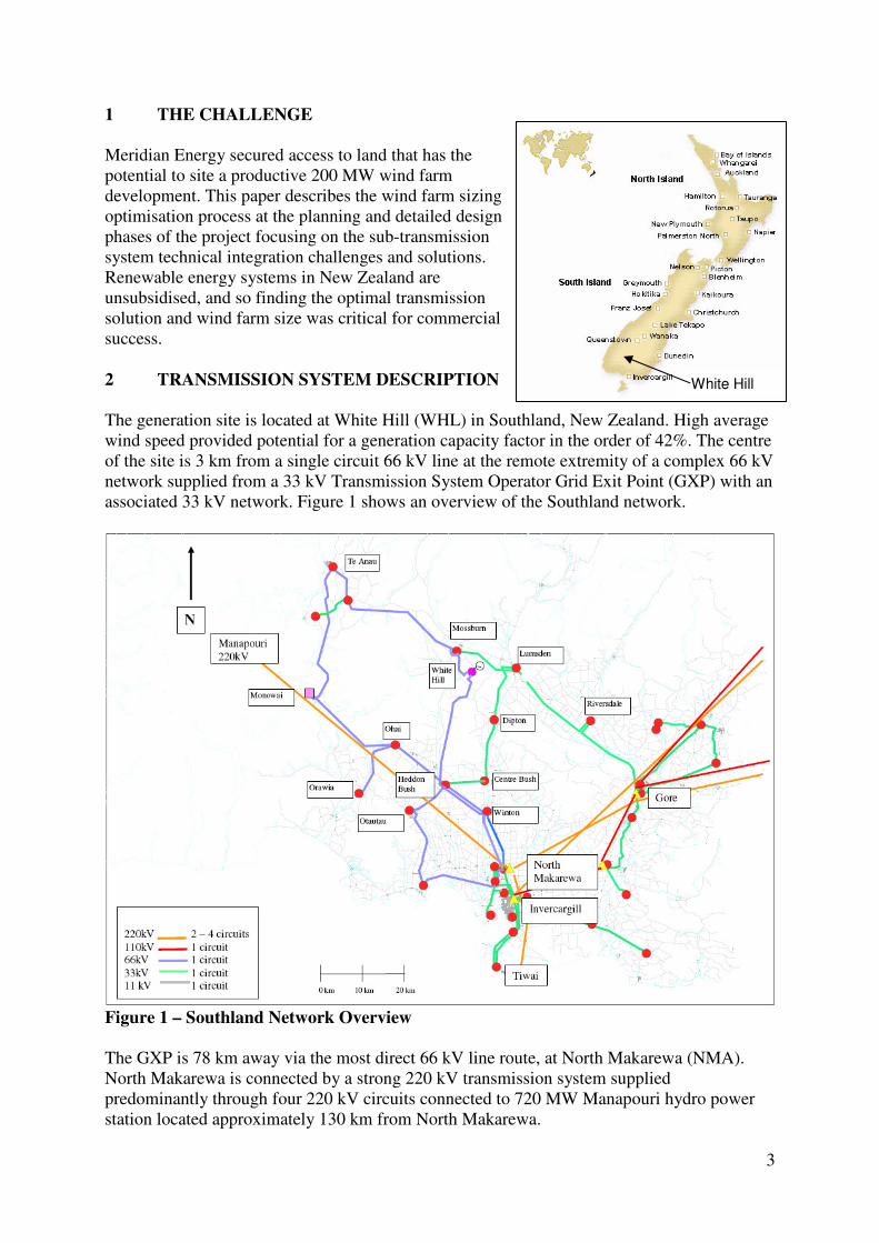
The generation site is located at White Hill (WHL) in Southland, New Zealand. High average
wind speed provided potential for a generation capacity factor in the order of 42%. The centre
of the site is 3 km from a single circuit 66 kV line at the remote extremity of a complex 66 kV
network supplied from a 33 kV Transmission System Operator Grid Exit Point (GXP) with an
associated 33 kV network. Figure 1 shows an overview of the Southland network.
Figure 1 – Southland Network Overview
The GXP is 78 km away via the most direct 66 kV line route, at North Makarewa (NMA).
North Makarewa is connected by a strong 220 kV transmission system supplied
predominantly through four 220 kV circuits connected to 720 MW Manapouri hydro power
station located approximately 130 km from North Makarewa.
White Hill
4
North Makarewa supplies a 33 kV distribution network from two 220 kV/ 33 kV 30/60 MVA
step down transformers. The GXP is unusual in that it feeds the extensive 66 kV network
through two 33 kV / 66 kV 30/40 MVA step up transformers.
Step down transformer substations to 11 kV are distributed around the 66 kV and 33 kV
networks. The distributed load around the area supplied from North Makarewa varies from
approximately 5 MW to 45 MW, with 7 MW of other existing embedded generation. Power
quality requirements for the wind farm are relatively stringent due to the needs of offtake
customers distributed around the extensive 11 kV networks.
3 INITIAL INVESTIGATIONS
Initial load flow studies using synchronous generator models suggested that the site was
limited to approximately 54 MW during normal system conditions due to thermal constraints.
By replacing a short section of conductor on a 66 kV line section near Winton; this could be
lifted to approximately 70 MW.
Power loss analysis showed that the increased losses in the Distribution Network Operator’s
(DNO’s) network would be high during peak generation, light load conditions, where up to
15% of the generation would be lost. Revenue for the generator would be based on the net
incremental power provided in the network by the wind farm, that is the wind farm generation
less incremental network power losses. High power losses at 70 MW would make the project
uneconomic.
A number of transmission upgrade options were investigated to lift the potential generation
levels and reduce power losses. These included
(a) connecting into the nearby 66 kV network only,
(b) (a) plus connecting into a 33 kV line connected to the remote Gore GXP
(c) Upgrading existing 33 kV lines within the North Makarewa sub-transmission network
to 66 kV
(d) Establishing a new 220 kV line and direct connection to the transmission grid.
Due to difficult approval processes and time and budgetary constraints, it was not possible to
upgrade or build new transmission lines and so option (a) was selected. Environmental
approvals were therefore sought and received for a 70 MW wind farm.
Design of wind farm on-site equipment showed that the optimum single line diagram for the
wind farm was for five 22 kV cable strings connected radially to the wind turbines from a
central 22 kV substation where the voltage would be stepped up to 66 kV through a single
transformer to connect to the nearby sub-transmission line.
3.1 POWER QUALITY STANDARDS
The initial phase of the optimisation process required the investigation of appropriate power
quality standards for a large embedded wind farm largely through interpretation of the grid
codes applicable for the development, and negotiation of standards with the DNO and
Transmission System Operator (TSO).
The DNO and TSO had different approaches to power quality targets. The DNO was most
concerned about the power quality experienced by customers distributed around its network.
For example, an important town popular to tourists, Te Anau, is located approximately 30 km
5
from the wind farm site and due to the remoteness from the GXP the wind farm has a strong
effect on its power quality. Therefore the DNO’s requirements were power quality
performance based. The wind farm should comply with all applicable codes, regulations and
standards and not adversely affect the level of service provided to network customers over the
full range of wind farm and network conditions. The TSO was more prescriptive with its
targets requiring fault ride through and adequate power system response following specific
transmission faults.
The power system in the South Island has a peak load of approximately 2000 MW and a
trough load of approximately 1200 MW. It is relatively sensitive to large instantaneous
changes of generation or demand and therefore it is desirable but not mandatory for the wind
farm to ride through most network and grid faults.
At the request of the TSO, the wind farm should be designed to operate during weak system
conditions. The most onerous case chosen was light load conditions with only two 135 MVA
generators connected at Manapouri and one 220 kV/33 kV transformer in service at North
Makarewa.
The wind farm’s design must be such that the power quality within the network is within
standards after faults at the wind farm or within the DNO or TSO networks.
Table I – Primary Local Requirements
Parameter Requirement
1 Permitted voltage
variations at WHL
66 kV during normal
network operation
Generally allows the 66kV network to operate such that the
regulated 11kV voltage to supply customers is within
obligations. This is +5%/-3% at NMA and approximately +5%/-
8% at WHL
2 Requirements
regarding power factor
control
• As per point 1 above
• Maintain GXP power factor within 0.95, or less than 5 Mvar
interchange
3 Response to faults Fault ride through required for 66kV, 33kV & 11kV network
faults and close-in transmission grid faults
4 Maximum expected
frequency changes
during disturbances
-3 to +2 Hz
5 Maximum expected
voltage unbalance
during normal grid
operation
2.6%
6 Harmonics • no significant harmonic to be introduced by WHL wind
turbines
7 Ripple Control Signal • A ripple control system operates within the distribution
network via 217 Hz signal. Injection level = 2%
• Wind turbines shall not cause voltages at 217 Hz in excess of
0.7% of the main voltage at the 66 kV connection
• The wind farm shall not absorb excessive 217 Hz so that
control signals are lost at the 11 kV level
8 Flicker AS/NZS 61000.3.7:2001 - 0.8 Pst and 0.6 Plt

6
3.2 MODEL DEVELOPMENT
The cornerstone of the modelling was the development of an accurate power system model.
Largely due to high productivity and satisfactory economic considerations, 2 MW Doubly
Fed Induction Generators (DFIGs) Wind Turbine Generators (WTGs) were selected for the
wind farm. The WTG supplier provided a model for its WTGs in a form suitable for a popular
dynamic power system analysis tool. This dictated the software application chosen for
dynamic power system modelling.
Development of the model required sourcing and verifying a model of the South Island
transmission system in the form suitable for the modelling package and converting an existing
steady state distribution network model into a suitable form, reviewing its parameters, joining
it to the transmission system model and verifying the complete power system model. Network
data in the form of network diagrams, transmission line configuration data, metering records,
and protection diagrams and settings was gathered and used to create and verify the model.
Figure 2– Complex Model Development and Verification
Initial dynamic studies investigated the power system scenarios and events that should be
tested. Light load cases with minimum system strength caused by the outage scenarios
required by the DNO and TSO proved to be the most onerous. Short circuit ratios of two or
less were encountered. The network load can be as low as 5 MW so that the bulk of the wind
farm’s output, less losses, would be exported to the distant GXP under high wind conditions.
High generation (more than approximately 30 MW) study results under some scenarios and
events ranged from overload of subtransmission assets to severely out of range voltages at the
11 kV customer level, to loss of supply to the entire Southland distribution network due to
cascade failure.
7
Studies showed that 27 faults out of 64 potential fault scenarios would require testing under
both minimum system strength and light load conditions, as well as high strength and high
load conditions and combinations of these with varying levels of site export.
4 DETAILED DESIGN AND NETWORK ENHANCEMENT OPTIONS
The maximum generation from the site was found to be approximately 25 MW without
significant network enhancements. Various enhancements were trialled in order to lift the
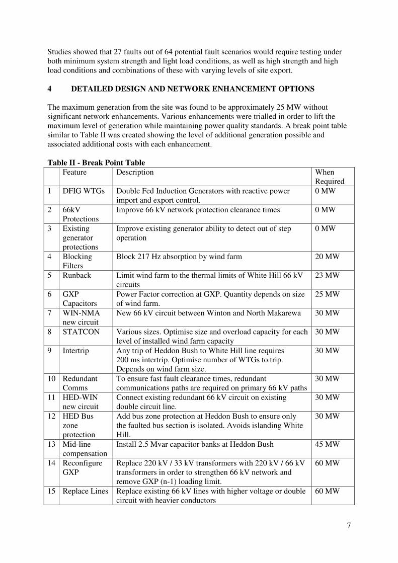
maximum level of generation while maintaining power quality standards. A break point table
similar to Table II was created showing the level of additional generation possible and
associated additional costs with each enhancement.
Table II - Break Point Table
Feature Description When
Required
1 DFIG WTGs Double Fed Induction Generators with reactive power
import and export control.
0 MW
2 66kV
Protections
Improve 66 kV network protection clearance times 0 MW
3 Existing
generator
protections
Improve existing generator ability to detect out of step
operation
0 MW
4 Blocking
Filters
Block 217 Hz absorption by wind farm 20 MW
5 Runback Limit wind farm to the thermal limits of White Hill 66 kV
circuits
23 MW
6 GXP
Capacitors
Power Factor correction at GXP. Quantity depends on size
of wind farm.
25 MW
7 WIN-NMA
new circuit
New 66 kV circuit between Winton and North Makarewa 30 MW
8 STATCON Various sizes. Optimise size and overload capacity for each
level of installed wind farm capacity
30 MW
9 Intertrip Any trip of Heddon Bush to White Hill line requires
200 ms intertrip. Optimise number of WTGs to trip.
Depends on wind farm size.
30 MW
10 Redundant
Comms
To ensure fast fault clearance times, redundant
communications paths are required on primary 66 kV paths
30 MW
11 HED-WIN
new circuit
Connect existing redundant 66 kV circuit on existing
double circuit line.
30 MW
12 HED Bus
zone
protection
Add bus zone protection at Heddon Bush to ensure only
the faulted bus section is isolated. Avoids islanding White
Hill.
30 MW
13 Mid-line
compensation
Install 2.5 Mvar capacitor banks at Heddon Bush 45 MW
14 Reconfigure
GXP
Replace 220 kV / 33 kV transformers with 220 kV / 66 kV
transformers in order to strengthen 66 kV network and
remove GXP (n-1) loading limit.
60 MW
15 Replace Lines Replace existing 66 kV lines with higher voltage or double
circuit with heavier conductors
60 MW
8
The “when required” column in Table II shows the approximate break point in wind farm
installed capacity above which each feature is required. Generally the features were additive
and required previous features in the table to be added in order to lift the potential generation
level.
Low system strength scenarios had one GXP transformer out of service as described above.
Test cases examined single circuit or bus contingency faults only as the wind farm output can
be limited manually if circuits are taken out of service for maintenance.
A commercial model was used to test the incremental wind farm development costs at each
break point including network enhancement costs. At 60 MW it was found that the
incremental costs outweighed the benefits.
Generally the detailed design focused on dynamic and transient operation (rather than steady
state limits) which tended to be the generation level limiting factor in this relatively weak
network. The most challenging fault cases were found to be those near the wind farm or on
the GXP 33 kV network as these caused either the greatest or longest duration voltage drops
seen by the WTGs and were therefore difficult to ride through.
Voltage and reactive power control was found to be particularly challenging. At 70 MW
generation with minimum local demand, more reactive power was imported from the GXP
than active power exported (61 MW exported, 64 Mvar imported). This resulted in poor
voltage regulation and high power losses. Power factor control at three points (White Hill,
Heddon Bush and the GXP) became necessary. Existing 11 kV voltage regulation is via on
load tap changers on the distribution transformers. Wind variation would cause greater
voltage fluctuation at the customer level without wind farm voltage control and distributed
capacitors.
4.1 DFIG WTGs - Instead of simple induction generator WTGs, doubly fed induction
generators were necessary to enable the wind farm to ride through system faults. The
DFIG generators increase their reactive power export levels during network faults in
order to keep the wind farm 22 kV reticulation system voltage above WTG trip levels
during network faults. The DFIG’s ability to import and export reactive power also
enables the wind farm to control network voltages that would otherwise vary greatly
during normal changes in network loading and wind farm generation levels.
4.2 Network Protection Upgrades - Protection tuning and upgrades were necessary to
ensure that faults on the primary 66 kV circuits clear within 200 ms to avoid wind
farm trips and voltage control issues during these fault scenarios. In general the 66 kV
network’s protections were upgraded to transmission level standards. An extensive
communications network is required. For high wind farm capacity options protection
design was challenging as there are two non-classical components of fault current
generated by the STATCON (positive and negative sequence VARs) that provide the
dominant source of fault current in this weak network. This produced very real risks of
protection mal-operation, incorrect directionality and potential failure of protection
systems to operate when required to do so. 66 kV line differential protection was
installed where required as the primary protection with distance relays provided as
secondary protection.
4.3 Existing Generator Protections – An existing embedded generator within the
distribution network was found to have a tendency to become out of step during
network faults. This would become worse and cause network instability if generation
9
was developed at White Hill. New undervoltage protection settings were proposed at
the existing power station to trip the units before they caused network instability.
4.4 Ripple Blocking Filters - The DNO injects 217 Hz control signals into the sub-
transmission network to control loads connected to the 11 kV network. The ripple
signal is injected at North Makarewa and controls loads as far away as Te Anau. The
wind farm and the capacitor banks at North Makarewa and Heddon Bush may absorb
the ripple such that its signal is too weak to control loads within some parts of the
DNO’s network. Filters were required on the capacitors and the wind farm in order to
block the ripple signal from being sunk by them.
4.5 Wind Farm Runbacks – Runbacks automatically ramp down the wind farm output to
the remaining circuit’s capability if one of the two 66 kV circuits connecting the wind
farm is disconnected. After activation by a circuit outage, the runback system
periodically ramps up the wind farm output to test the network capacity and limits the
wind farm output accordingly or resets the runback. The system allows the wind farm
to ramp up the line loading above the continuous rating in order to utilise the lines’
inherent overload capacity.
4.6 GXP Power Factor Correction - Under high power export conditions high levels of
reactive power are absorbed by the transfer of power from the wind farm to the GXP.
This requires high levels of reactive power to be imported from the GXP. Due to the
distance involved, the provision of reactive power at the wind farm provides little
benefit at the GXP. The final solution required four 66 kV 5 Mvar shunt capacitor
banks at the GXP to correct power factor. The capacitor controller monitors the GXP
reactive power flow and operates the capacitors automatically to improve the power
factor. These capacitors also switch automatically on +/-5% off-nominal voltage levels
and can be operated remotely from the DNO’s control room in Invercargill. To a lesser
extent they assist with network voltage control and assist to bring the voltages back
within standards following network faults. Capacitor bank size was limited by the size
of the transient voltage step during switching which is approximately 1.5% of nominal
per bank.
4.7 New Line Section - The DNO installed a new 20 km long 66 kV circuit between the
TSO GXP and Winton in order to satisfy increased demand and network security
requirements. This improved the wind farm’s viability by reducing losses, adding an
additional path during parallel line fault scenarios and marginally increasing short
circuit levels at the wind farm.
4.8 STATCON - A wind farm STATCON connected to the 22 kV switchboard is required
to improve the ability of the wind farm to ride through transient power system faults
and improve post fault voltage quality. Initially it was thought that a thyristor switched
reactor may be sufficient to bring down high voltages on fault recovery that would
otherwise cause the WTGs to trip, however further simulations showed that faster
acting assistance in both under and over voltage situations was required. The
STATCON assists to keep the wind farm 22 kV reticulation system voltage above
WTG trip levels during network faults. During some network fault situations with high
wind farm generation, the power system would be unstable without the STATCON in
service. A 6 MVA STATCON was selected at the 58 MW level. The selected
STATCON has a 267% 2 second overload capacity which is an efficient means of
providing high levels of dynamic support for the short transient time frames required
during system faults. The STATCON consists of 1 MVA modules. If a module fails
the STATCON automatically de-rates and its remaining capacity is sufficient for
normal wind farm operation. The STATCON also provides steady state voltage to a
minor extent and dispatches the WTGs’ reactive power output.

10
Figure 3 – White Hill Wind Farm Substation
4.9 Inter-trip - An inter-trip system trips a number of turbine 22 kV cable strings at the
wind farm instantaneously whenever a circuit breaker on either end of the Heddon
Bush to White Hill 66 kV line opens and the wind farm is generating more than
30 MW. The intertrip ensures that the wind farm generation is immediately reduced to
30 MW or less. Without this feature, the power system could become unstable when a
fault occurs on this line resulting in WTG overvoltage trips and/or in further line
protection operations and potentially cascade failure. Tripping of the WTGs is
required within 200 ms of fault inception. The WTGs and STATCON that remain in
service assist to stabilise the system voltages during and following the fault clearance.
Following the fault, a wind farm runback becomes active to continue to limit the farm
to approximately 23 to 30 MW.
4.10 Communications - In order to ensure operation of the inter-trip system, redundant
communications were required between Heddon Bush, the wind farm and other critical
substations.
4.11 Network Reconfiguration – Half of an existing double circuit line between Heddon
Bush and Winton was unused. Reinstatement of the circuit improved the wind farm’s
viability by reducing losses, added an additional path during parallel line fault
scenarios and marginally increasing short circuit levels at the wind farm. By joining
this to the new line section in point 7 above and bypassing Winton, faults at or close to
Winton on the other Winton circuits have a lower impact on the wind farm.
4.12 Heddon Bush Bus Zone Protection – Add two bus zone protections to the Heddon
Bush 66 kV switchyard to ensure that only the faulted bus section trips on a bus fault.
This avoids islanding the wind farm due to bus faults.
4.13 Mid-line Compensation - Under high power export conditions high levels of reactive
power are absorbed by the transfer of power from the wind farm to the GXP. Mid-line
compensation within the 66 kV network was found to be an efficient means of
reducing network reactive power needs and is provided by two 66 kV 2.5 Mvar shunt
capacitor banks at Heddon Bush. These assist with voltage control around the 66 kV
network during load and wind farm generation variations and also assist with voltage

11
control post fault in radial parts of the network emanating from the central part of the
network. These capacitors switch automatically on +/-2.5% off-nominal voltage levels.
They can also be operated remotely from the DNO’s control room in Invercargill.
Capacitor bank size was limited by the size of the transient voltage step during
switching which is approximately 1.5% of nominal per bank.
4.14 GXP Rebuild - The GXP transformers are thermally limited which limits the potential
wind farm output during transformer outages. The existing GXP is unusual in that the
220 kV voltage is stepped down to 33 kV to supply a 33 kV network before it is
stepped up to 66 kV to feed the 66 kV network. The combined impedances of the
transformers significantly reduce the short circuit levels in the 66 kV network,
reducing the strength, stability and controllability of the network during grid or
network faults. An option to overcome this was to feed the 66 kV network directly
from low impedance 220 kV transformers. A further advantage was that this would
completely separate the existing 33 kV network, which has slower fault clearance
times, from the 66 kV network, therefore improving the ability of the WTGs to ride
through 33 kV network faults. This option was not chosen due to its high cost.
4.15 New Sub-Transmission Lines - Replacement of existing 66 kV single circuit lines
with double circuit lines along the main route between the wind farm and the GXP
would reduce power losses and the reliance on the single circuits and marginally lift
short circuit levels at the wind farm improving stability and fault ride through
performance. This option was not chosen due to its high cost and potentially difficult
approval processes.
Circuit single phase fault clearance by single phase circuit breaker trip and auto-reclose was
investigated and not adopted as three phase faults were found to be more onerous and must be
catered for first.
The final solution adopted a 58 MW wind farm with enhancements 1 to 13. The dynamic
studies indicate that the power system remains stable and the wind farm continues to operate
for all power system faults except for some faults within the 33 kV network connected to
North Makarewa when the network load is low, White Hill generation is above 30 MW and a
North Makarewa 220 kV/33 kV or 33 kV/66 kV transformer is out of service. In this case a
number (or all) of the wind farm turbines may be tripped off by their voltage protections
however the power system will recover with voltages around the network returning to
acceptable levels. The DNO and TSO agreed to accept these rare scenarios.
5 OPERATIONAL EXPERIENCE
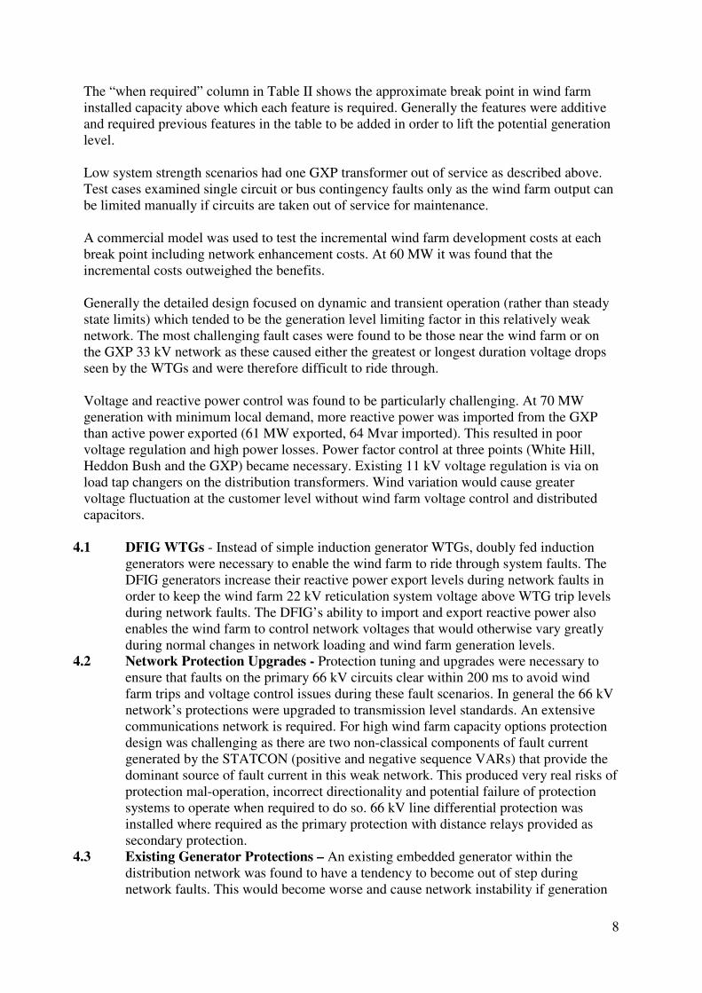
Power flow at the GXP now varies greatly with periods of significant export into the grid as
shown in Figure 4.
12
Figure 4 – Power flow change at North Makarewa GXP
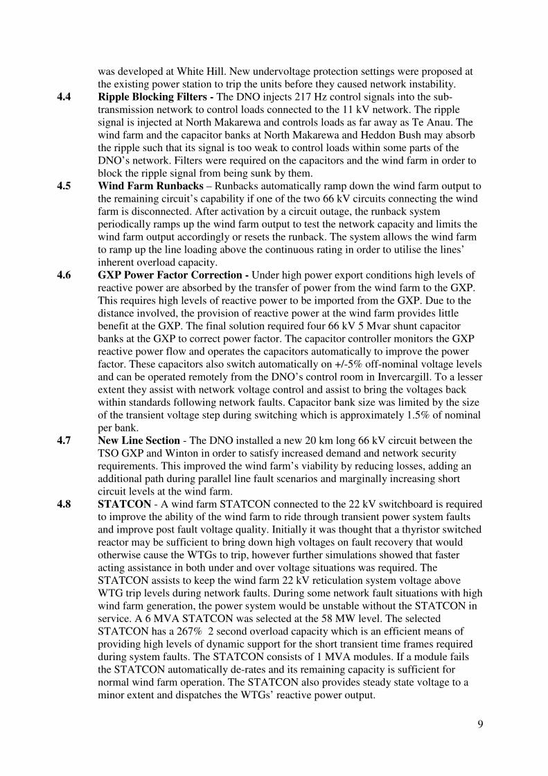
Various network faults have occurred and analysis is undertaken to determine if the system is
reacting as expected and if adaptation of the settings and/or configuration is desired. An
adaptive approach is taken with close monitoring and ongoing analysis to enhance the
performance of the control schemes, in order to achieve suitable outcomes for the connected
consumers.
Figure 5 – White Hill recordings 12th of December 2007 during 33 kV NMA fault
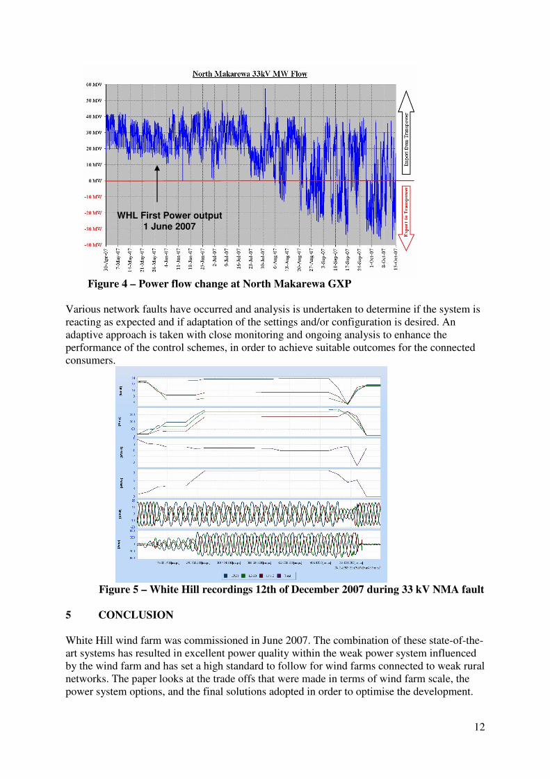
5 CONCLUSION
White Hill wind farm was commissioned in June 2007. The combination of these state-of-the-
art systems has resulted in excellent power quality within the weak power system influenced
by the wind farm and has set a high standard to follow for wind farms connected to weak rural
networks. The paper looks at the trade offs that were made in terms of wind farm scale, the
power system options, and the final solutions adopted in order to optimise the development.
WHL First Power output 1 June 2007