optimization and design of four gripper ...57 rubik’s cube, pneumatical manipulator, service...
TRANSCRIPT
57
Rubik’s cube, Pneumatical manipulator, Service robotics, Thistletwaite45
Mikuláš HAJDUK*, Jozef VARGA
**, Frantisek DUROVSKY
***
OPTIMIZATION AND DESIGN OF FOUR
GRIPPER PNEUMATICAL RUBIK’S CUBE
SOLVER
Abstract
Robotic Rubik’s solver is an excellent example of science popularizing
mechatronic device, since it combines knowledge of several technological
fields including computer vision techniques, advanced numerical
algorithms and control of industrial pneumatic components with popula-
rity of Rubik’s cube in one resulting device. First version of solver con-
structed by our department was equipped only by 2 lower grippers, resul-
ting in approximately four minutes for single cube solution. Proposed
paper describes not only experience gained by development of upgraded
4 gripper version but includes statistical analysis of Thistlethwait’s 45
algorithm required for solving process optimization. Mechanical design,
electronics, system overview, performance and limitations of upgraded
4 gripper version are explained in detail as well.
1. INTRODUCTION
Rubik’s cube is famous puzzle invented by Erno Rubik in 1974. 57mm wide
cube consisting of 6 center, 8 edge and 12 corner pieces, allows more than
43x1018
mutual combinations. Consequently, solving the Rubik’s cube like
many other problems is the NP-hard problem (see: eg. [1-5]). Since Rubik’s
cube introduction, its popularity has inspired many students and researchers
to build robots capable of solving this 3D puzzle. Several solving mechanisms
have been proposed already [6], most of them using NXT components, but some
pneumatical robots have been constructed as well [7]. Considering speed,
David’s Gilday’s Cubestormer III is the current Guinness world record holder
in category Fastest Rubik’s cube solving robot - time 3.253s [8].
* Department of Production Systems and Robotics, Faculty of Mechanical Engineering,
Technical University of Kosice, 042 00 Kosice Slovakia, [email protected] **
[email protected], ***
58
No matter what mechanics is used, the principle of real cube solving process
remains the same including three phases: Detection of cube state, Generating
solution and Realizing particular moves. Proposed paper describes mechanical
construction in first section, followed by solving algorithm description, system
overview, electronics specification and statistical analysis of Thistlethwait’s 45
algorithm. Last section provides information from real testing including solving
times and personal experience gained during several public presentations of this
showpiece. The main drawback of the whole system identified during
presentation phase was vision based cube detection algorithm. It’s weakness is
mainly caused by mechanical construction, because in order to keep clear
industrial design, USB webcam is not only opposite-visitor oriented,
but moreover mounted on gooseneck platform, which prevents long-term fixed
position of camera with respect to handled cube. Every time the showpiece is set
up, the position of the camera slightly changes. This drawback in combination
with various lighting conditions during several day-long presentations requires
more robust algorithm for cube detection than the one previously used.
The development of robust computer vision algorithm for Rubik’s Cube state
detection can be found in [9].
2. MECHANICAL CONSTRUCTION
As mentioned in the beginning, our motivation was to by develop fully
pneumatical Rubik’s cube solver to demonstrate possibilities of pneumatical
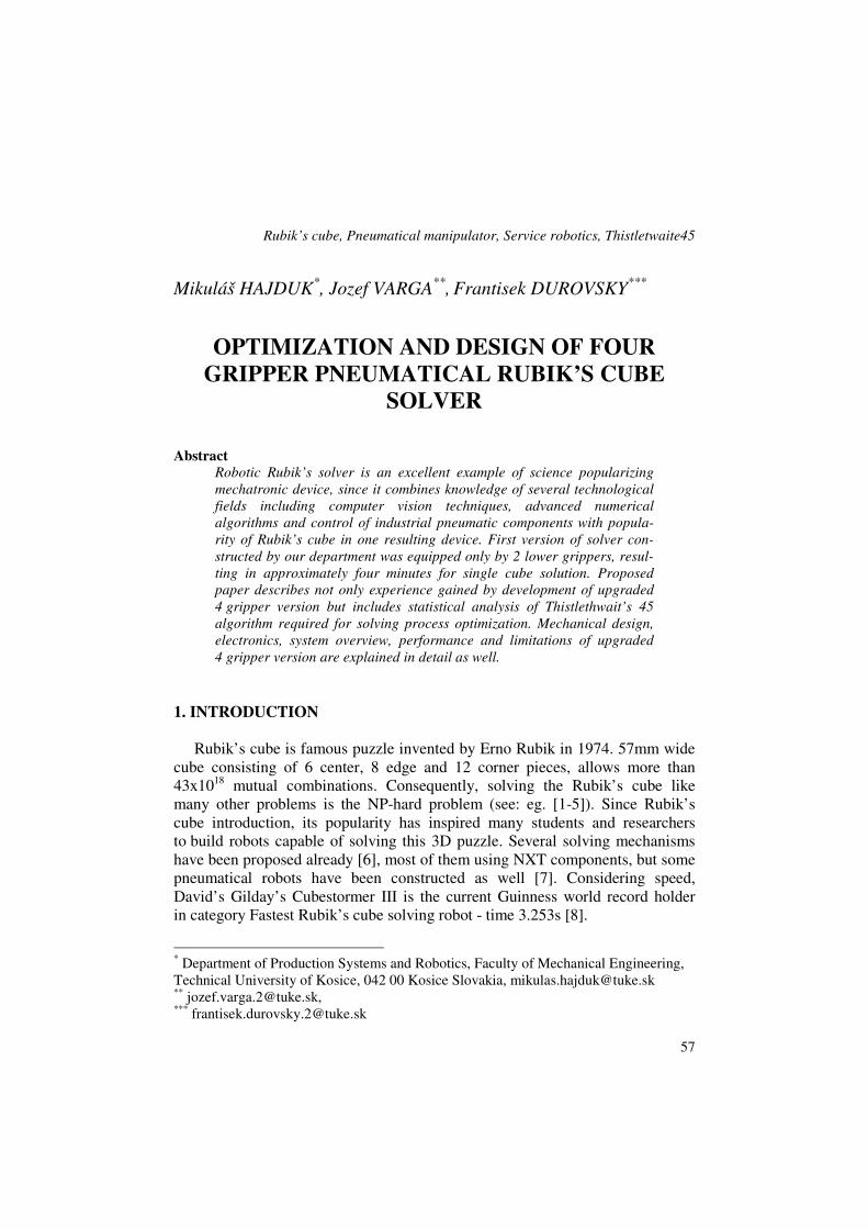
approach in precise manipulation tasks. 3D CAD design shown in Fig. 1 gives
an overview of whole construction.
Fig. 1. Mechanical design of Rubik’s solver [source: own study]
59
Supporting frame is assembled of aluminum mounting profiles 30x30mm and
attached to wooden base providing cover for electronic part of a system.
Four manipulation units consist of three air modules – compact guide cylinder,
rotary table and a gripper module. For our particular construction, SMC modules
were used, since they provided best price/performance ratio.
The very first component that needed to be selected in Rubik’s solver
mechanical design was gripper unit. SMC provides several types of components
including angle, parallel or three point grippers. Considering all possible options,
MHL parallel units were selected as best suitable for our task. MHL in general
are double piston parallel style grippers with large holding force, which are
available in several sizes.
In order to select particular type of MHL gripper module, it was necessary to
compute holding force and determine holding point distance. If Rubik’s cube
weight is mrc = 0,12 kg , safety factor k = 10 , then required holding force
is computed as follows:
NkgmF rku 8,11=××= (1)
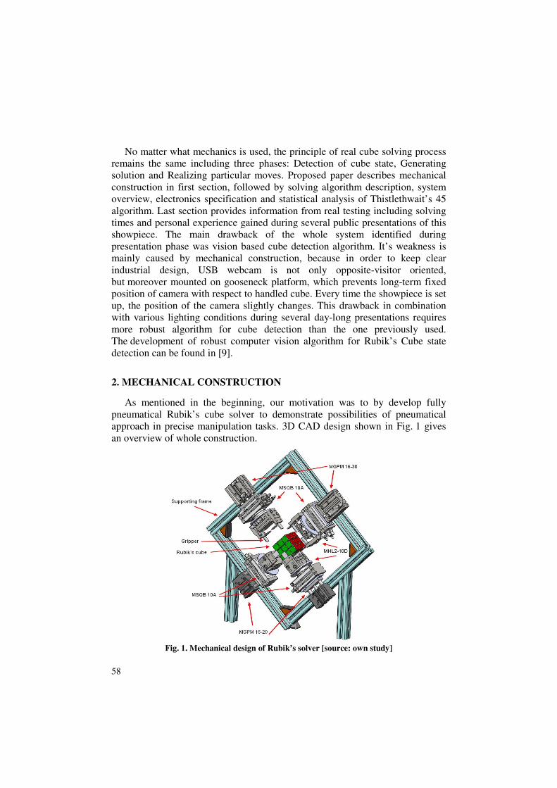
Considering holding force uF , distance from grasping point R = 30 mm and
Rubik’s cube width L = 57 mm , MHL2-10D unit, providing opening/closing
stroke range 56-76 mm was selected. As shown in diagram in Fig. 2 required
holding force can be achieved already at 0.4 MPa.
Fig. 2. MHL2-10D gripper unit and appropriate
holding force graph [source: own study]
Rotation of gripper unit is handled by SMC MSQ units. MSQ is compact
rotary table including load bearings, mounting face, with a rack-and-pinion style
rotary acutator. Achievable rotating range of MSQ tables is 190 degrees, in case
of Rubik’s cube manipulation; adjustments are set to 0-90°. In order to select
60
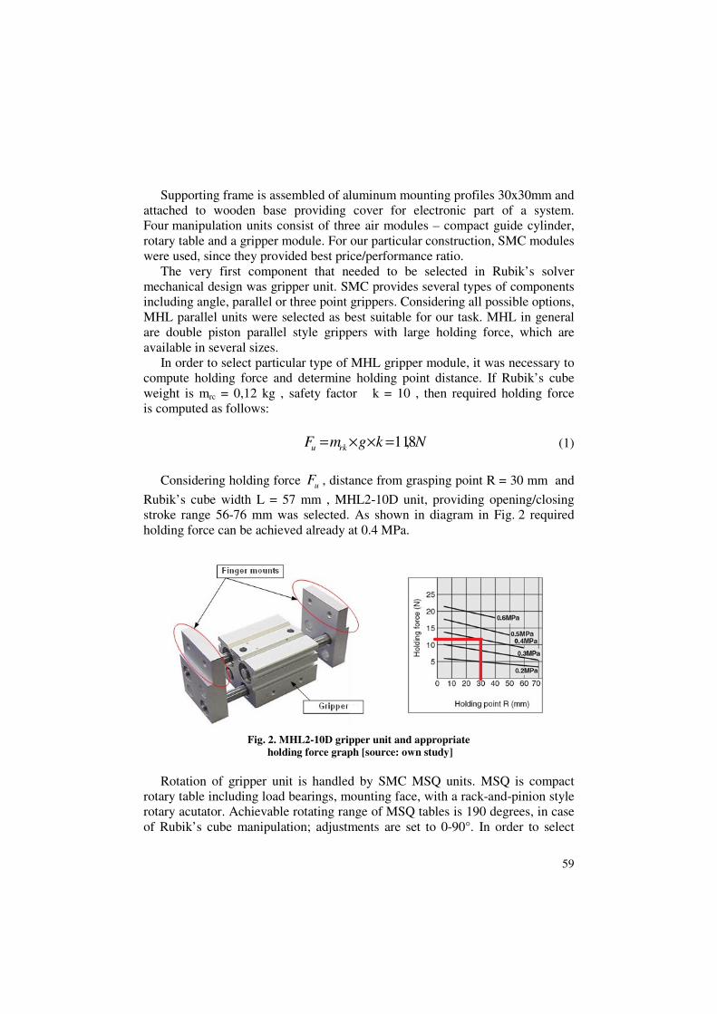
optimal rotary table type, two important variables - moment of inertia and time
of 90° rotation must be determined. Considering weight of Rubik’s cube mrc =
0,12 kg , weight of gripper unit mGU = 0,28 kg as well as dimensions of gripper
unit, moment of inertia can be computed as follows:
2422
1051,112
)( kgmba
mmI GUrc
−
×=+
×+= (2)
If duration of 90 degree rotation is set to 0.3s, MSQB-10A unit meets
computed requirements as shown in diagram in Fig. 3.
Fig. 3. MSQB-10A unit and appropriate rotation time –
inertial moment selection graph [source: own study]
As mentioned above, current mechanism allows manipulating with four sides
of cube directly. But solving process require clockwise and counterclockwise
manipulation with all six sides of the cube, therefore it is necessary to turn the
cube every time the front or back side of the cube needs to be rotated.
However, turning the cube without stroking of particular units is not possible
because of mutual gripper collisions. Application of compact guide cylinders
eliminates this problem, by providing stroking capability for each manipulation
unit. When rotating the cube, only gripper holding the cube can be ejected,
remaining three must be shut to avoid collision. From all available cylinder
units, MGPM class was most suitable for our construction mainly because of its
flat design and rectangular mount allowing simple attachment of rotary unit.
61
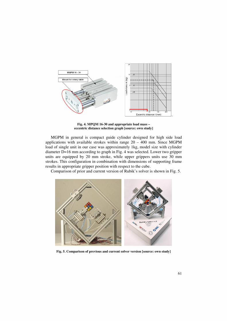
Fig. 4. MPQM 16-30 and appropriate load mass –
eccentric distance selection graph [source: own study]
MGPM in general is compact guide cylinder designed for high side load
applications with available strokes within range 20 – 400 mm. Since MGPM
load of single unit in our case was approximately 1kg, model size with cylinder
diameter D=16 mm according to graph in Fig. 4 was selected. Lower two gripper
units are equipped by 20 mm stroke, while upper grippers units use 30 mm
strokes. This configuration in combination with dimensions of supporting frame
results in appropriate gripper position with respect to the cube.
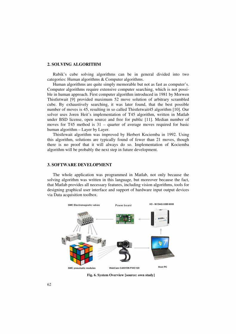
Comparison of prior and current version of Rubik’s solver is shown in Fig. 5.
Fig. 5. Comparison of previous and current solver version [source: own study]
62
2. SOLVING ALGORITHM
Rubik’s cube solving algorithms can be in general divided into two
categories: Human algorithms & Computer algorithms.
Human algorithms are quite simply memorable but not as fast as computer’s.
Computer algorithms require extensive computer searching, which is not possi-
ble in human approach. First computer algorithm introduced in 1981 by Morwen
Thistletwait [9] provided maximum 52 move solution of arbitrary scrambled
cube. By exhaustively searching, it was later found, that the best possible
number of moves is 45, resulting in so called Thistletwait45 algorithm [10]. Our
solver uses Joren Heit’s implementation of T45 algorithm, written in Matlab
under BSD license, open source and free for public [11]. Median number of
moves for T45 method is 31 – quarter of average moves required for basic
human algorithm – Layer by Layer.
Thistlewait algorithm was improved by Herbert Kociemba in 1992. Using
this algorithm, solutions are typically found of fewer than 21 moves, though
there is no proof that it will always do so. Implementation of Kociemba
algorithm will be probably the next step in future development.
3. SOFTWARE DEVELOPMENT
The whole application was programmed in Matlab, not only because the
solving algorithm was written in this language, but moreover because the fact,
that Matlab provides all necessary features, including vision algorithms, tools for
designing graphical user interface and support of hardware input output devices
via Data acquisition toolbox.
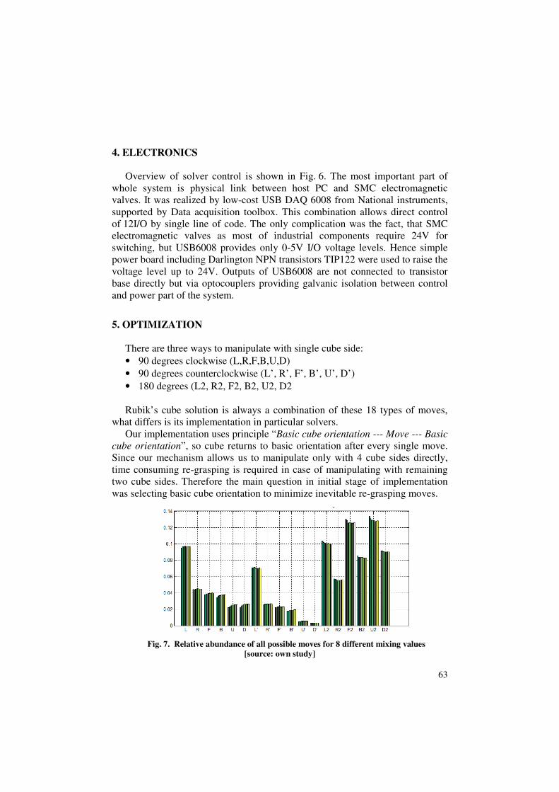
Fig. 6. System Overview [source: own study]
63
4. ELECTRONICS
Overview of solver control is shown in Fig. 6. The most important part of
whole system is physical link between host PC and SMC electromagnetic
valves. It was realized by low-cost USB DAQ 6008 from National instruments,
supported by Data acquisition toolbox. This combination allows direct control
of 12I/O by single line of code. The only complication was the fact, that SMC
electromagnetic valves as most of industrial components require 24V for
switching, but USB6008 provides only 0-5V I/O voltage levels. Hence simple
power board including Darlington NPN transistors TIP122 were used to raise the
voltage level up to 24V. Outputs of USB6008 are not connected to transistor
base directly but via optocouplers providing galvanic isolation between control
and power part of the system.
5. OPTIMIZATION
There are three ways to manipulate with single cube side:
• 90 degrees clockwise (L,R,F,B,U,D)
• 90 degrees counterclockwise (L’, R’, F’, B’, U’, D’)
• 180 degrees (L2, R2, F2, B2, U2, D2
Rubik’s cube solution is always a combination of these 18 types of moves,
what differs is its implementation in particular solvers.
Our implementation uses principle “Basic cube orientation --- Move --- Basic
cube orientation”, so cube returns to basic orientation after every single move.
Since our mechanism allows us to manipulate only with 4 cube sides directly,
time consuming re-grasping is required in case of manipulating with remaining
two cube sides. Therefore the main question in initial stage of implementation
was selecting basic cube orientation to minimize inevitable re-grasping moves.
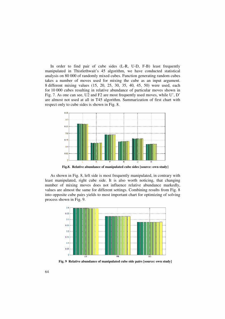
Fig. 7. Relative abundance of all possible moves for 8 different mixing values
[source: own study]
64
In order to find pair of cube sides (L-R, U-D, F-B) least frequently
manipulated in Thistlethwait’s 45 algorithm, we have conducted statistical
analysis on 80 000 of randomly mixed cubes. Function generating random cubes
takes a number of moves used for mixing the cube as an input argument.
8 different mixing values (15, 20, 25, 30, 35, 40, 45, 50) were used, each
for 10 000 cubes resulting in relative abundance of particular moves shown in
Fig. 7. As one can see, U2 and F2 are most frequently used moves, while U’, D’
are almost not used at all in T45 algorithm. Summarization of first chart with
respect only to cube sides is shown in Fig. 8.
Fig.8. Relative abundance of manipulated cube sides [source: own study]
As shown in Fig. 8, left side is most frequently manipulated, in contrary with
least manipulated, right cube side. It is also worth noticing, that changing
number of mixing moves does not influence relative abundance markedly,
values are almost the same for different settings. Combining results from Fig. 8
into opposite cube pairs yields to most important chart for optimizing of solving
process shown in Fig. 9.
Fig. 9 Relative abundance of manipulated cube side pairs [source: own study]
65
It is obvious that “Up-Down” pair is statistically least manipulated, so when
following general Rubik’s cube notation:
Up side – White center square
Left side– Green center square
Front side – Red center square
Down side – Yellow center square
Right side – Blue center square
Back side – Orange center square
It means that in order to minimize time-consuming re-grasping, white and
yellow center sides needs to be front/back oriented with respect to the solver,
while Green, Blue, Red and Orange cube sides are directly reachable
by particular grippers.
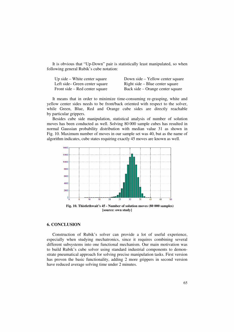
Besides cube side manipulation, statistical analysis of number of solution
moves has been conducted as well. Solving 80 000 sample cubes has resulted in
normal Gaussian probability distribution with median value 31 as shown in
Fig. 10. Maximum number of moves in our sample set was 40, but as the name of
algorithm indicates, cube states requiring exactly 45 moves are known as well.
Fig. 10. Thistlethwait’s 45 - Number of solution moves (80 000 samples)
[source: own study]
6. CONCLUSION
Construction of Rubik’s solver can provide a lot of useful experience,
especially when studying mechatronics, since it requires combining several
different subsystems into one functional mechanism. Our main motivation was
to build Rubik’s cube solver using standard industrial components to demon-
strate pneumatical approach for solving precise manipulation tasks. First version
has proven the basic functionality, adding 2 more grippers in second version
have reduced average solving time under 2 minutes.
66
Rotary table allowing movement only between two endpoints is the main
constraint of current mechanism. In case of Rubik’s solver, endpoints are
mechanically set to 0 and 90 degrees. It is possible to solve the cube with such
a limitation but frequent time-consuming re-grasping is required. Optimal end-
points for clockwise, counterclockwise and double moves would be -90, 0, 90
and 180 degrees. Replacing current rotary units for stepper motors could rapidly
reduce solving time to less than one minute, but for the price of simple
pneumatical design.
Video of proposed Rubik’s cube solver developed by our department
is available on http://www.youtube.com/watch?v=-VhLoyQBhj8.
7. FUTURE WORK
Rubik’s cube solver is the main presentation showpiece used by Faculty
of Mechanical engineering during several science popularizing actions. Authors
of this paper have spent hours and hours presenting this mechanism in public,
while solving hundreds of cubes randomly mixed by visitors.
Mechanical construction as well as electronic part of system has proven its
reliability during this period, though no further upgrades of these parts are
foreseen. What is worth considering is the robot control software since new
solving algorithms have been released recently. Implementation of more
advanced algorithms could reduce average number of moves and thus reduce
overall solving time even more.
Rubik’s solver is also a great experimental platform for testing different
vision algorithms. In future, we would like to try different approach to move
from static image recognition to video tracking of the cube. Moreover existing
dataset of positive and negative scans could be also used to train a support vector
machines algorithm for cube position detection. Such an approach has the
potential to bring more sophisticated solution and reduce the scan time
significantly.
Rubik’s Cube solver was funded by grant project of Dean of Faculty of
Mechanical Engineering, no. FGV/2013/1
REFERENCES
[1] HAMTA N., GHOMI S.M.T.F., JOLAI F., BAHALKE U.: Bi-cirteria assembly line
balancing by considering flexible operation times. Applied Mathematical Modelling,
2011, Vol. 35, Issue 12, pp. 5592-5608.
67
[2] GOLA A., ŚWIĆ A., KRAMAR V.: A multiple-criteria approach to machine-tool
selection for focused flexible manufacturing systems. Management & Production
Engineering Review. Vol. 2, No 4, 2011, p. 21-32.
[3] GOLA A., ŚWIĆ A.: Algorytm generowania ścieŜek techno-logicznych w procesie
doboru obrabiarek, Zarządzanie Przedsiębiorstwem, Nr 1, 2011, s. 8-16 (in Polish).
[4] DONG J., CHEN Y., ZHANG A., YANG Q. F.: A new three-machine shop scheduling
complexity and approximation alghoritm. Journal of Combinatorial Optimization, Vol.
26, Issue 4, 2013, pp. 799-810.
[5] JUMAN Z.A.M.S., HOQUE M.A.: A heuristic solution on technique to attain the minimal
total cost bound of transporting a homogeneous product with varying demands and supplies.
European Journal of Operational Research, Vol. 239, Issue 1, 2014, pp. 146-156.
[6] Cube solving robots http://www.speedsolving.com/wiki/index.php/List_of_cube_
solving_robots
[7] LU S. L., HUANG M., KONG F. R.: The Design of a Rubik's Cube Robot. Advanced
Materials Research, 709 (2013), pp. 432-435.
[8] CubeStormer III http://gizmodo.com/lego-robot-with-a-smartphone-brain-shatters-
rubiks-cub-1544556295.
[9] DUROVSKY F.: Robust Rubik’s Cube detection. Applied Mechanics and Mechatronics,
vol. 611, 2014, pp. 253-264.
[10] Progressive improvements in solving algorithms http://cubeman.org/dotcs.txt.
[11] Open source implementation of Thistleswait45 algorithm by Joren Heit – Mathworks file
exchange http://www.mathworks.com/ matlabcentral/fileexchange/31672-rubiks-cube-
simulator-and-solver.