optimization on fuel gas operation for combined...
TRANSCRIPT

OPTIMIZATION ON FUEL GAS OPERATION FOR COMBINED CYCLE
POWER PLANT
MOHD IZAMUDDIN BIN MAHMUD
A project report submitted in partial fulfillment of the
requirements for the award of the degree of
Master of Engineering (Electrical-Power)
Faculty of Electrical Engineering
Universiti Teknologi Malaysia
JUNE 2011

iv
To my friends and family for your support and advise.

v
ACKNOWLEDGEMENTS
Alhamdulillah. I would like to express my appreciation to Associate Professor
Dr Mohd. Wazir bin Mustafa for his relentless effort in supporting and guiding to
complete this research. The guidance, knowledge sharing, and advice will be noted
for the next undertaking.
I also would like to acknowledge my thank you to Alstom O&M team in
Perlis Power Plant, the senior O&M manager Mr Stefan Kesseler, the technical
advisor Mr Chamnan Thabsuk and senior mechanical engineer Mr Marc Lamprecth
for the knowledge sharing, advice and support.
Lastly, a special thanks to Ms Noraziah Wahi and Mr Zulkiflee Elia from
UiTM Kota Samarahan, Mr Albert Bun, Mr Suresh from UTM, Mr Iskandar and Mr
Nazir from Lumut Power Plant and Associate Professor Dr Zulkurnain from IVAT.
vi
ABSTRACT
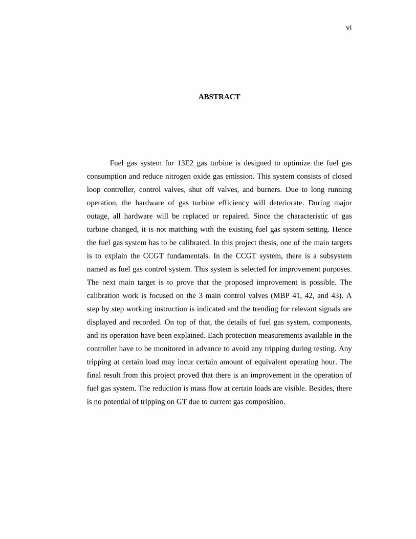
Fuel gas system for 13E2 gas turbine is designed to optimize the fuel gas
consumption and reduce nitrogen oxide gas emission. This system consists of closed
loop controller, control valves, shut off valves, and burners. Due to long running
operation, the hardware of gas turbine efficiency will deteriorate. During major
outage, all hardware will be replaced or repaired. Since the characteristic of gas
turbine changed, it is not matching with the existing fuel gas system setting. Hence
the fuel gas system has to be calibrated. In this project thesis, one of the main targets
is to explain the CCGT fundamentals. In the CCGT system, there is a subsystem
named as fuel gas control system. This system is selected for improvement purposes.
The next main target is to prove that the proposed improvement is possible. The
calibration work is focused on the 3 main control valves (MBP 41, 42, and 43). A
step by step working instruction is indicated and the trending for relevant signals are
displayed and recorded. On top of that, the details of fuel gas system, components,
and its operation have been explained. Each protection measurements available in the
controller have to be monitored in advance to avoid any tripping during testing. Any
tripping at certain load may incur certain amount of equivalent operating hour. The
final result from this project proved that there is an improvement in the operation of
fuel gas system. The reduction is mass flow at certain loads are visible. Besides, there
is no potential of tripping on GT due to current gas composition.

vii
ABSTRAK
Sistem bahan bakar gas di dalam gas tarbin 13E2 telah direkacipta untuk
mengoptimasikan penggunaan bahan api gas dan mengurangkan penghasilan gas
nitrogen oksida. Sistem ini terdiri dari kawalan litar tertutup, injap terkawal, injap
tertutup, dan alat pembakar. Disebabkan jangka masa operasi yang lama, tahap
kecekapan peralatan dan pekakas gas tarbin turut menurun. Di dalam proses
pemulihan secara besar-besaran, kesemua pekakas and peralat utama akan ditukar
atau dibaiki. Oleh kerana sifat-sifat gas turbin telah berubah, ia tidak lagi sesuai
dengan konfigurasi system bahan bakar gas pada waktu itu. Dengan itu, sistem bahan
bakar gas perlu di perbetulkan semula. Tujuan utama projek tesis ini adalah untuk
menerangkan fungsi and operasi CCGT secara asas. Di dalam sistem ini, terdapat
subsistem dipanggil sistem bahan bakar gas. Sistem ini telah di pilih untuk kerja
penambahbaikan. Selain itu, tesis ini bertujuan untuk membuktikan bahawa cadangan
penambahbaikan mampu mengurangkan penggunaan bahan api gas. Kerja
pembetulan konfigurasi tertumpu kepada 3 injap terkawal utama (MBP 41, 42, dan
43). Cara kerja secara khursus telah di tunjukkan dan informasi berkaitan telah di
rekod. Selain itu, sistem bahan bakar gas, perkakas yang berkaitan dan cara operasi
telah diterangkan secara khursus. Setiap data yang berkaitan dengan keselamatan dan
perlindungan yang terdapat di dalam sistem pengawal telah di perhatikan secara
langsung. Projek ini membuktikan bahawa penambahbaikan di dalam sistem bahan
bakar gas adalah tidak mustahil. Terdapat tahap pengurangan jumlah penggunaan
bahan api pada Megawatt tertentu. Selain itu, tiada potensi untuk GT tidak
berkemampuan menjalankan tugas di sebabkan komposisi gas semasa.

viii
TABLE OF CONTENT
CHAPTER TITLE PAGE
DECLARATION ii
DEDICATION iv
ACKNOWLEDGEMENT v
ABSTRACT vi
ABSTRAK vii
TABLE OF CONTENTS viii
LIST OF TABLES xi
LIST OF FIGURES xii
LIST OF ABBREVIATIONS xv
LIST OF SYMBOLS xvi
LIST OF APPENDICES xvii
1 INTRODUCTION
1.1 Research Background 1
1.2 Power Business Liberation 4
1.3 Impact of Uncertainty in Power Business 6
1.4 Problem Statement 9
1.5 Objective of Study 10
1.6 Scope of Study 11
1.7 Thesis Structure 12
2 COMBINED CYCLE POWER PLANT
2.1 Introduction 13

ix
2.2 Combined Cycle Power Plant 15
2.3 Overview of Gas Turbine 17
2.3.1 Operation of Gas Turbine 28
2.4 Overview of steam turbine 30
2.4.1 Operation of Steam Turbine 35
2.5 Balance of plant 37
2.6 Summary 40
3 FUEL GAS CONTROL VALVES
3.1 Introduction 41
3.2 Operation concept of fuel gas control valve 42
3.2.1 Fuel gas valve control system 49
3.2.2 Calibration of pilot control valve 54
3.3 Detail and design of EV burner 55
3.4 Safety operations and monitoring of GT 59
3.5 Controllers 62
3.5.1 Close loop controller for GT 63
3.5.2 Open loop controller for GT 65
3.5.3 Protection controllers for GT 65
3.5.4 Node controllers for GT 65
3.5.5 Node controller for HRSG 66
3.5.6 Node controller 17 66
3.5.7 Node controller 18 67
3.5.8 Node controller 19 67
3.5.9 Close loop controller for ST 67
3.5.10 Protection controllers for ST 68
3.6 Summary 68

x
4 CALIBRATION OF FUEL GAS CONTROL VALVES
4.1 Introduction 69
4.2 Working instruction 69
4.3 Control valves initial settings 70
4.4 First stage of calibration 73
4.5 Second stage of calibration 82
4.6 Third stage of calibration 91
4.7 Forth stage of calibration 105
4.8 Summary 115
5 RESULT AND DISCUSSION
5.1 Introduction 116
5.2 Results 116
5.2.1 Calibration of MBP 41 control valve 117
5.2.2 Calibration of MBP 42 control valve 119
5.2.3 Calibration of MBP 43 control valve 121
5.3 Discussion 123
6 CONCLUSION AND RECOMMENDATION
6.1 Conclusion 124
6.2 Recommendation 125
REFERENCES 127
APPENDIX A 130

xi
LIST OF TABLES
TABLE NO. TITLE PAGE
2.1 Gas property from PETRONAS 27
3.1 Settings for pulsation 60
4.1 Original stroke and mass flow values 71
4.2 Calibration of MBP 43 control valve 81
4.3 Calibration of MBP 41 and MBP43 control valves 90
4.4 Calibration of MBP 41, 42 and 43 control valves 104
4.5 Calibration of MBP 41 control valve 114
5.1 New and old mass flow data for MBP 41 118
5.2 New and old mass flow data for MBP 42 120
5.3 New and old mass flow data for MBP 43 122

xii
LIST OF FIGURES
FIGURE NO. TITLE PAGE
2.1 Flow chart of selecting the MBP control valves 16
2.2 Gas turbine overview 18
2.3 Overview of generator single line diagram 19
2.4 Overview of plant electrical single line diagram 20
2.5 Overview of GT lubrication system 22
2.6 Hydraulic safety oil 23
2.7 Overview of GT fuel oil system 23
2.8 GT release criteria 24
2.9 GT tripping system 25
2.10 GT shaft monitoring system 25
2.11 Overview of by-pass system 31
2.12 Overview of condenser system 32
2.13 Overview of feedwater system 33
2.14 Overview of HRSG and drums systems 34
2.15 Overview of steam turbine system 35
2.16 Cooling water system 39
2.17 Fuel gas forwarding system 40
3.1 Fuel gas valves overview 42
3.2 Control valves operating concept 44
3.3 GT fuel gas system diagram 46
3.4 Fuel gas overview 47
3.5 Burner arrangement 48
3.6 Picture of MBP 41 control valve 49
3.7 Control valve single line diagram 50
xiii
3.8 Control valve at close position 51
3.9 Control valve starts to open 52
3.10 Control valve fully open 52
3.11 Control valve starts to close 53
3.12 Power oil drain 54
3.13 Burner diagram 59
3.14 Burner head 57
3.15 Air and fuel gas flow 58
3.16 Burners inside combustor 59
3.17 Temperature after turbine profile 62
3.18 Typical controllers in CCGT 63
3.19 Control valve controller 64
4.1 MBP 41 valve characteristic 72
4.2 MBP 42 valve characteristic 72
4.3 MBP 43 valve characteristic 73
4.4 Calibration at 5MW 75
4.5 Calibration at 10MW 76
4.6 Calibration at 15MW 77
4.7 Calibration at 20MW 78
4.8 Calibration at 25MW 79
4.9 Calibration at 30MW 80
4.10 Linear graph of MBP 43 control valve 81
4.11 Calibration at 20MW 83
4.12 Calibration at 25MW 84
4.13 Calibration at 30MW 85
4.14 Calibration at 35MW 86
4.15 Calibration at 40MW 87
4.16 Calibration at 45MW 88
4.17 Calibration at 50MW 89
xiv
4.18 Linear graph of MBP 41 control valve 90
4.19 Calibration at 35MW 92
4.20 Calibration at 40MW 93
4.21 Calibration at 45MW 94
4.22 Calibration at 50MW 95
4.23 Calibration at 55MW 96
4.24 Calibration at 60MW 97
4.25 Calibration at 65MW 98
4.26 Calibration at 70MW 99
4.27 Calibration at 75MW 100
4.28 Calibration at 80MW 101
4.29 Calibration at 85MW 102
4.30 Calibration at 90MW 103
4.31 Linear graph of MBP 42 control valve 105
4.32 Calibration at 95MW 106
4.33 Calibration at 100MW 107
4.34 Calibration at 105MW 108
4.35 Calibration at 110MW 109
4.36 Calibration at 115MW 110
4.37 Calibration at 120MW 111
4.38 Calibration at 125MW 112
4.39 Calibration at 130MW 113
4.40 Linear graph of MBP 41 control valve 114
5.1 Old and new graph of MBP 41 control valve 119
5.2 Old and new graph of MBP 42 control valve 121
5.3 Old and new graph of MBP 43 control valve 123
xv
LIST OF ABBREVIATIONS
DC - Direct current
TNB - Tenaga Nasional Berhad
NLDC - National Load Dispatch Center
CCPP - Combined Cycle Power Plant
GT - Gas Turbine
ST - Steam Turbine
BOP - Balance of Plant
PETRONAS - Petroliam Nasional Berhad
HRSG - Heat Recovery Steam Generator
VIGV - Variable Inlet Guide Vane
TAT - Temperature After Turbine
TIT - Temperature Inlet Turbine
O&M - Operation and Maintenance
HVCB - High Voltage Circuit Breaker (275kV)
GCB - Generator Circuit Breaker (15.75kV or 19kV)
AGC - Automatic Generation Control
CLC - Closed Loop Controller
OLC - Opened Loop Controller
NOx - Nitric Oxide and Nitrogen Dioxide
PLS - Protection Load Shedding
BDQ - Bad Data Quality
CCGT - Combined Cycle Gas Turbine
EOH - Equivalent Operating Hours

xvi
LIST OF SYMBOLS
B - Magnetic force
F - Force
f - Frequency, hertz
I - Current, ampere
Kg/s - kilogram per second
m3/h - meter cube per hour

xvii
LIST OF APPENDICES
APPENDIX NO. TITLE PAGE
A BRAYTON CYCLE 130
1
CHAPTER 1
INTRODUCTION
1.1 Research Background
Technical approach is a modification of the processes and parameters
adjustment of the Combine cycle power plant. The modification of the processes may
start from the input (fuel, air, steam etc.) until the power has been delivered to the
customer. The settings adjustment shall be carried out along the process as stated
before. Both reconfigurations are essential, as it will determine the quantity and
quality of final product hence affecting the efficiency of the combine cycle power
plant. However certain calibration may be limited due to material and safety
constrain.
As far as cost of operating and maintaining are concerned, the technical
approach proposed will determine the minimum overall cost yet maximizing the
profits. While overall costs reduce, the higher profits may reflex the performance of
the operation and maintenance personnel and plant. The minimum operation and

2
maintenance cost also may affect the chances of the new operation and maintenance
tender, as it will become a referral.
A suitable technical approach may be implemented base on the current
economic situation. The situation may vary from inflation and deflation of economy
and planned outage. When the economy is inflated or deflated, each gas turbines and
steam turbine shall be equipped with the suitable technical parameters and hence the
unique efficiency has been determined. The efficiency may become a guideline
during selection for the gas turbine to operate. The highest efficiency is the most
favorable to operate as far as profit is concerned. In scheduling the inspection or
outage for each unit, the equivalent operating hours (EOH) will become the
guidelines. Here the most efficient unit after the new technical approach is applied
will be in the schedule first and usually with higher equivalent operating hours
interval than others.
In determining the highest capable efficiency, of each unit, the processes and
parameters will be adjusted and recalibrated. The recommendation will be based on
the virtual model adjustment. The model will be designed base on the actual combine
cycle power plant to get the accurate effect during testing.
In a research paper in reference [1], it was introduced the method of
investment planning in power plant business. The decision tree is used. The input
criteria are no investment, large repair or replace the power plant, and the failure risk
cost. At the end of the process, the profits and plants operating rates for each period
shall be determined.

3
The design technical approach will increase the efficiency of the Gas and
Steam Turbines. Hence the cost of operate and maintain will reduce. Indirectly the
additional profit margin will be given to the Operation and Maintenance (O&M)
company. If the cost of the O&M were imposed in the bidding process, it will project
a good competitive advantage especially to new O&M company.
In the reference [2-5], it was explained that there are few papers were
presented as part of the PowerGen exhibition. It was meant to promote the new
design of F class GT. Among the improvements are the new tested compressor design
by using 6 sigma methodology, the new single center tie bolt rotor and the new
exhaust system. On top of that, it was claimed that the start reliability may achieve
from zero speed to base load in 10 minutes. However there was no further
information in regards to the combined cycle operation improvement. Nevertheless,
in relation to this project, this paper may introduce a room of improvement for the
13E2 design review. Further redesign and test are required to be on par with this new
product by Siemens.
In addition to the references above, it was explored on the NOx emission and
reduction for the gas turbine outlet. An equipment was introduced called Lean Head
End (LHE) with water and steam injection technique as the testing was carried out at
partial and base load. It is proven effective with GT frame 5, 6, and 7.
The writer in the as referred in the Reference [6] also put proposal on
optimization by cascading the LNG cycle, Rankine cycle using ammonia-water as a
working fluid and Brayton power cycle of power plant. Nevertheless, it was not
recorded the actual implementation of such a combination yet.

4
1.2 Power Business Liberalization
The power market’s liberalization throughout the main global economy
player’s (USA and EU for example) had been triggered in the mid 1990’s, hence
exerting changes in the power generation and supply businesses of these economies.
As a result of this, nowadays, power plant operators had to experience more
challenging market environment such as due to strong competition, various
uncertainties, and many without long term power purchase agreements. Like a
blessings in disguise, the market liberalization also presents new business
opportunities such as the utilization of market price fluctuations for operation and
maintenance optimization, participation in ancillary service markets, and short term
trading.
All of these opportunities can contribute to significantly improve the operating
margins. By knowing how to approach these challenges as well as opportunities, an
operator can in some cases achieve higher profits and enhance their marketability,
without depending too much on long term power purchase agreement which although
guarantee security in part of the operators but is still vulnerable towards various
uncertainties such as political uncertainties that might review, reconsider or even
change completely the accepted policy towards power businesses. Apart from that,
these form of dependency of operations on contracts or agreements also restrict power
businesses from exploring new opportunities, business ideas and in some extreme
uncertain environment will even led operations to go on without profit.
A study was conducted on the liberalization impact on the electricity market
as the reference [7] is referred. The focus was toward the coal mining industry. There

5
are 2 scenarios discussed (monopoly and liberation) with the specification of
commercialization and privatization, competition, and authorization for the client to
buy the power directly from producer.
Furthermore, the more experience gained from operating under liberalized
market environment would actually enhances an establishment competitive advantage
in order to operate and survive anywhere as the global economic interactions
continuously becoming more liberalized with more freedom to invest in new
geographical market of varying uncertainties in various terms, thus the supremacy of
the fittest eventually dominates globally.
As the reference of [8] is referred, the paper is using Gatecycle program as an
assistant for simulation. There are 16 inputs parameters manipulation. They are
temperature of GT combustor exit, live steam, HP vaporizer, LP superheater, water
LTE and EH, duct burner temperature rise, pressure of LP steam, HP steam, and ST
extraction, natural gas ratio, flow rates of compressed air from GT and LP, GT air
compressor pressure ratio, efficiencies of heat exchange and steam re-heater. It was
proposed to have a mixture of CCGT with integration with steel plant. The air
separation unit (ASU) is also part of the system

6
1.3 Impact of Uncertainty in Power Business
The current economic, social, and political climate in which the electric power
industry operates has changed considerably in the last 40 years. Prior to the end of the
1950s, planning for the construction of plant facilities was basically straightforward
because it could be assumed that the load would at least double every 10 years.
Therefore, past trends provided a relatively simple guide for the future. During the
1960s, generation unit sizes increased and high voltage transmission and
interconnections between utilities expanded rapidly to take advantage of the
economics of scale. The utility industry economic environment was relatively stable
prior to the 1970s. Both inflation and interest rates were predictable, and
consequently costs did not change rapidly. Therefore, the uncertainties associated
with most aspects of utility finance were minimal, and economic studies could be
performed with some degree of certainty.
The oil embargo of the early 1970s disrupted the economic stability of the
utility industry. The industry was faced with escalating fuel costs in addition to the
possibility of supply interruptions. Furthermore, the United States was experiencing
rapid increases in interest rates. These factors represented a reversal of long-standing
trends. Public concern for depleting the earth's limited resources along with concern
for the environmental impact added to the challenges confronting the utility industry.
In addition, the cost of nuclear power was escalating due to new and much rigorous
regulations, which made it evident that nuclear power was not going to be a universal
supply for the world’s energy needs.

7
In view of reference [9], this paper introduces a method of energy planning by
using energy flow optimization model (EFOM). In this paper, the exploration of multi
types of plants and implementation of available saving energy techniques are put into
this study. It was shown also that the reduction of emission of the coal based power
plant.
The past decade has seen a growing recognition that policies that ignore
uncertainty often lead in the long run to unsatisfactory technical, social, and political
outcomes. As a result, many large corporations and federal agencies now routinely
employ decision analytic techniques that incorporate explicit treatment of uncertainty.
Uncertainty is a major issue facing electric utilities in planning and decision-making.
Substantial uncertainties exist concerning future load growth, construction times and
costs, performance of new resources, and the regulatory and economic environment
in which utilities operate. During the past decade, utilities have begun to use a variety
of analytical approaches to deal with these uncertainties. These methods include
sensitivity, scenario, portfolio, and probabilistic analyses. As typically applied, these
methods involve the use of a computer model that simulates utility operations over 20
or 30 years. Fuzzy numbers were also used to model non-statistical uncertainties in
engineering economic analysis.
Technology, in businesses aspect can be expressed as all the assets either
physical or non-physical (ideas, knowledge, processes, procedures and etc.) that are
being applied homogenously together to bring out the deliverable products either
physical or non-physical (such as services). In most businesses nowadays, the use or
the ability to use technology in their approach towards delivering intended products is
one of the key elements towards establishing competitive advantage. A classical
example to examine this advantage is in the case of an agricultural business

8
employing machineries in their operations versus an agricultural business that doesn’t
employ machineries but instead relying much on labor-intensive approach in their
operations. In a period of certainty, obviously the former would hold an advantage
over the later, but during a period of uncertainty, the elements which made up the
advantages might not be tolerated by these uncertainties, for example when there is a
an inflation of fuel price, an entity which rely much on machineries would have to
decide whether to absorb the spike in operation expenditure or to distribute it to the
market to which will definitely lower their competitive advantage significantly
brought about by possible market reactions. This example although crude and
simplistic in nature, but is sufficient to show just how much the approach of
technology can be affected by uncertainties. Therefore, by approaching technology
with versatility, uncertainties may be tolerated up to certain degree to which the
competitive advantage can still be upheld.
For any profit oriented organizations, whatever they do, whatever decisions
the top managements made, whatever approach (technological or technical, financial
and etc.) they applied, the final target of all these is no more than to achieve economic
objective of these establishments, in the sense of generating optimum wealth for
various purpose; expansion, new investments, upgrading, debt pay-up, and so on. So
after going through all the series of complexity, the final and most important variable
coming out from all these, is merely a simple numeric values of the economic cost or
price per base units of products, and from this value the other possibilities are
regularly calculated, decided and modified where possible in order to come out with
the best possible final value that can potentially tolerate for all other expectations.
There are few simulations have been carried out on the relation with power
plant. They are in reference [10]. This paper introduces the simulation and design of

9
fault logic simulation for the HP heater in the 210 MW thermal power plant. The
other sample is explored in reference [11].This project modeled the 2 gas turbines and
1 steam turbine configuration of CCGT by using the Matlab software. The data from
simulation are compared with real time plant.
1.4 Problem Statement
With respect to what had been discussed previously. It is now obvious that,
the power industries are becoming increasingly vulnerable towards various
uncertainties, especially economic uncertainties. Economic uncertainties such as
during the period of inflation as well as during the period of deflation would certainly
exert some effects on the economics of this industry. A simple way to define or
mathematically express the economics of an individual power entity is proposed as
follow, assuming a fully liberalized energy market:
Previous studies on the optimization of techno-economic relationship of
power plants had concluded that total or absolute optimization of this relationship up
to this moment is still unsolvable, but then again, certain categorical variables aspects
of the power plant can be potentially optimize to tolerate for pressure from external
circumstances such as various possibilities of economic uncertainties.
To do this, it is proposed that instead of trying to optimize the whole
interrelating variables, it could be easier or potentially reactive if only certain or

10
specific categorical aspect of the whole power plant business be optimized to achieve
the desired result. For that matter, certain categorical variables are considered or
assumed to be fixed while certain others are dynamic in nature, hence may be
predicted to certain value or extent which responds to the dynamics of various
probabilities coming from economic uncertainties, and finally certain other or a
specific categorical variables be manipulated or optimized to tolerate the dynamics of
the responding categorical variables.
This proposed study, predicts that the optimization of internal production
process variables or technical aspects of the major process components of combined
cycle power plants could potentially tolerate for the dynamic changes of the variables
that predictably responds to various probabilities that affects the economics and
operation of a power plant.
1.5 Objective of Study
a) To understand the operating concept of combined cycle gas turbine power
plant.
b) To studies and understand the detail design, operating concept, and safety
operation of fuel gas system.
11
c) To optimize and validate the new operation concept of fuel gas control valve
system.
1.6 Scope of Study
Since the general nature of the key subjects of the proposed topics are well
known to be quite broad as well as complex in nature, therefore several scope of
studies are put forward as the boundary to which this proposed study would
commence.
Apart from that, the technical aspect of the power plants will only be focused
on that regarding the process plants (production floor) and its major components as
well as its attaching variables, potentials and possibilities that can be related and
furthermore be manipulated for the purpose of this study.
The evaluation, discussion and conclusion on the optimization strategies
would be drawn on the basis of the real time on the recorded data used for this study
and therefore might be subjected to certain fixed limitation of this prescribed methods
and tools, hence the forms of which the results, data and information are being
processed and tabulated, in contrast with other available tools and methodological
approaches that are applicable in this field of studies.
12
1.7 Thesis structure
In chapter 2, we shall discuss the general principle of operation for the
combine cycle power plant. The 13E2 version is focused in this study. The combined
cycle plant selected has 3 main sections. They are 3 gas turbines, 3 HRSGs, and 1
steam turbine. Each section will be subdivided into smaller components for further
explanation on its function.
In chapter 3, the discussion will be on fuel gas system. It explained the
operation concept, the protection limits and the component involved such as the
control valve, burners, pilot control valve and the controllers.
Chapter 4 will show the results from the testing and procedure. Chapter 5 is
meant for the result and discussion. The next chapter is for conclusion and
recommendation. The final topic in this thesis would be the references and appendix.
127
REFERENCES
1. Keiichi Handa, Shigeru Matsumoto, Masashi Nakamoto, Naoshi Uchihira “An
Optimization Method for Investment and Maintenance Planning of Power
Plants under Uncertain Environments” IEICE Trans. Fundamentals, Vol.E88-
A, No.6 June 2005.
2. H.Emberger, Dr.D.Hofmann, C.Kolk “Economic Evaluation of Cycling Plants
– An Approach to Show the Value of Operational Flexibility.” PowerGen
Siemens AG 2007 Reference Power Plants.
3. Pratyush Nag, David Little, Damien Teehan, Kris Wetzl, David Elwood “Low
Load Operational Flexibility for Siemens G Class Gas Turbines” PowerGen
International, Orlando, Florida, December 2008.
4. Joshua Kovac “Advanced SGT6-500F Development” PowerGen
International, Orlando, Florida, December 2008.
5. Clifford Johnson, Barton Pepperman, Micheal Koenig, Khalil Abou-Jaoude,
Anil Gulati, Ali Moradia “Ultra Low Nox Combustion Technology”
PowerGen International, Orlando, Florida, December 2008.
6. T. Lu, K.S Wang “Analysis and Optimisation of A Cascading Power Cycle
with Liquefied Natural Gas (LNG) Cold Energy Recovery” Applied Thermal
Engineering, 29, 2009, 1478-1484.
7. Jacek Kaminski “The Impact of Liberalization of the Electricity Market on the
Hard Coal Mining Sector in Poland.” Energy Policy 37, 2009, 925-939.
8. M. Liszka, A. Ziebik “Economic Optimization of the Combined Cycle
Integrated with Multi-Product Gasification System” Energy Conversion and
Management, 50, 2009, 309-318.

128
9. J.Daniel, M. Dicorato, G. Forte, S. Iniyan, M. Trovato “A Methodology for
the Electrical Energy System Planning of Tamil Nadu State (India)” Energy
Policy 37, 2009, 904-914.
10. S.Srinivasan, P.Kanagasabapathy, K. Chitra, R. Pugazhendi, N.Selvaganesan
“Fault Simulation and Fuzzy Controller for High Pressure Heater in Thermal
Power Plant” Elektrika, 8(2), 2006, 5-12.
11. Faridah Mohamad Idris “Modeling of A Combine Cycle Power Plant”
Universiti Teknologi Malaysia, 2001, PSZ 19-16
12. Roya Ahmadi Ahangar, Abdolreza Sheykholeslami, Hamidreza Ghaffari
“Power Flow Modeling for Power Systems with Dynamic Flow Controller”
Elektrika, 10(2), 2008, 22-27.
13. R Gnanadass, Narayana Prasad Padhy, T.G. Palanivelu “A New Method for
the Transmission Congestion Management in the Restructured Power Market”
Elektrika, 9(1), 2007, 52-58.
14. J.O. Jaber “Photovoltaic and Gas Turbine System for Peak-Demand
Applications” International Journal of Engineering and Technology, 1(1),
2004, pp. 28-38.
15. Roointon Pavri, Gerald D. Moore “Gas Turbine Emission and Control” GE
Power Systems, GER4211, 2007, 03-01.
16. A. A. Rentizelas, I. P. Tatsiopoulos, A. Tolis “An Optimisation Model for
Multi-Biomass Tri-Generation Energy Supply” Biomass and Bio energy 33,
2009, 223-223.
17. Athnasios L. Chatzimouratidis, Petros A. Pilavachi “Technological, Economic
and Sustainability Evaluation of Power Plant using the Analytic Hierarchy
Process.” Energy Policy 37, 2009, 778-787.
18. Rainer Kurz “Gas Turbine Performance” Proceedings of The hirty-Forth
Turbomachinery Symposium, 2005.

129
19. Electric Machinery Committee “IEEE Standard for Cylindrical - Rotor 50 Hz
and 60 Hz Synchronous Generators Rated 10 MVA and Above” IEEE Std
C50.13, 2005.
20. International Standard “Rotating Electrical Machine – Part 3: Specification
Requirements for Cylindrical Rotor Synchronous Machine” IEC 2005, 60034-
3.
21. E. Smith “Main Generator Rotor Maintenance” Electric Power Research
Institute, 2006.