optimized data acquisition with the igi digitherm thermal ......fig. 10: footprint of the thermal...
TRANSCRIPT
Kremer 111
Optimized Data Acquisition with the IGI DigiTHERM Thermal Camera System
JENS KREMER, Kreuztal
ABSTRACT Airborne thermal infrared sensors are widely used for military applications since the 1950s. Since that time, advances in sensor technology have made thermal infrared imaging sensors better applicable and available for civil remote sensing tasks. Nevertheless, the complexity, price and weight of the sensors have limited the field of application strongly. Since about 10 years, thermal sensor arrays that do not require any scanning mechanism nor any cooling have created a mass market of thermal imagers (Schuster & Kolobrodov 2004). These sensors are relatively cheap and easy to use. The low weight and volume of such a Thermal IR (ThIR) camera allows for the integration of this technology into standard aerial survey systems and enables the extension of the range of possible applications. This paper describes the integration of an uncooled microbolometer camera into an existing modular aerial survey system. The components of the modular system are described and the result of a practical survey mission is shown.
1. INTRODUCTION
The improvements in the technology of thermal infrared imaging have lead to very small, light and easy to use ThIR cameras. Especially the availability of uncooled cameras has improved the applicability of this technology for commercial aerial survey companies. Nevertheless, the available uncooled microbolometer cameras are predominantly designed for applications such as the manual creation of heat loss images of houses and the control of industrial processes. They are not directly designed as airborne sensors. The DigiTHERM system is a modification and integration of such a camera into an existing modular aerial survey system. The deep integration with other system components, like a GNSS/IMU system, a navigation system and other sensors, like optical (VIS) cameras and LIDAR, open a wide range of new applications. Typical applications can be Diagnostics of heat insulation of buildings Power line monitoring Fire monitoring Monitoring of pipelines Diagnostics of long distance heating networks Hot spots in rubbish dumps Livestock monitoring Detection of archaeological remains etc.
The modular design allows to utilize common components of the survey system for different sensor combinations and to adapt to the varying needs of the different applications. Since the necessary weather-, light- and seasonal conditions for different sensor combinations are almost complementary, this concept can improve the usage rate of the survey platform significantly. For example, the very same aircraft, sensor navigation system, GNSS/IMU system, stabilized mount and camera control computer with storage can be used for a photoflight in daylight and for a ThIR flight in the night.

112 Kremer
2. SYSTEM LAYOUT
The DigiTHERM consists of one or more thermal cameras, a control computer and a graphical user interface on a touch screen display. In the standard configuration, these components are operated together with a CCNS navigation system and an AEROcontrol GNSS/IMU system.
2.1. The DigiTHERM
The DigiTHERM is based on the VarioCAM hr from InfraTec GmbH, Dresden, Germany. This camera works with an uncooled microbolometer array with VGA resolution (640 pixel * 480 pixel). The pixels have a pitch of 25µm, resulting in an active sensor area of 16mm * 12mm and a FOV of 29.9° * 22.6° (for the 30mm lens option). The camera operates in the spectral range between 7.5µm and 14µm. In the standard version, the temperature range is -40°C to 120°C and the thermal resolution is < 0.05K NETD (Noise Equivalent Temperature Difference).
Fig. 1: DigiTHERM ThIR camera. Fig. 2: Thermal infrared lenses for the DigiTHERM.
The available range of lenses provides a focal length between 12.5mm and 75mm. At a flying height of 300m, this results in Ground Sample Distances (GSD) between 60cm and 10cm. The example project shown in this paper was flown with a 30mm lens. The size of the sensor head (without lens) is 153mm * 91mm *111mm with a weight of 1.05kg. The uniformity of the temperature measurement over the complete sensitive area and the stability of the temperature measurement is maintained by a camera internal calibration process. In user selectable intervals, the sensor detects the temperature distribution of a special shutter. The result of this control measurement is used to calibrate the sensor. This procedure enables a highly homogeneous measurement even under conditions with a rapidly changing ambient temperature.
2.2. Sensor Control and Data Storage
The operator controls the thermal camera via a graphical user interface running on a touch-screen monitor (Figure 4). This control monitor is connected to the DigiCONTROL Sensor Management Unit (SMU) (Figure 3) (Minten 09). During data acquisition, the captured thermogram is displayed in real time. For this real time display, the operator can choose between different color palettes and adjust the temperature limits. The settings for the real time visualization do not influence the
Kremer 113
storage of the raw thermal data. Other settings, including the interval for the shutter of the internal temperature calibration, can be changed during the mission. Two different sets of images are stored separately. One folder contains the triggered images according to the flightplan. In a second folder, a continuous stream of images are captured with 6Hz. The recording of these images starts as soon as the system goes “online”. The exposure times for the images in both datasets are stored individually.
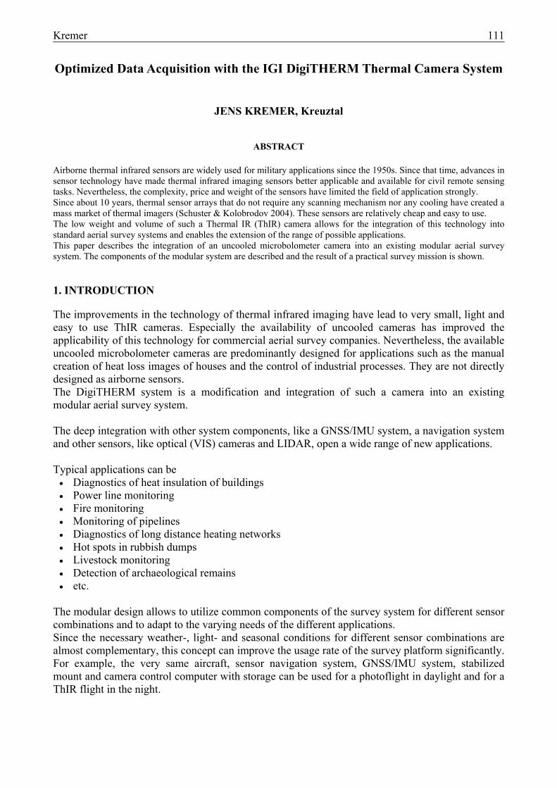
The raw thermal information is saved on the exchangeable storage unit inside the DigiCONTROL SMU containing a 250GB SSD. For the size of one thermal raw image of 602kB, one storage unit can hold about 18hours of continuous data capturing at six images per second. After the flight, the storage unit can be disconnected from the SMU to download the data in the office. If more than one storage unit is needed in a mission, the unit can be exchanged during the flight without shutting down the system. In the standard configuration, the
DigiTHERM is operated together with the AEROcontrol GNSS/IMU system. This system is running on another SMU that is bundled together with the camera's control computer (Figure 6). Both modules communicate to provide time synchronization between GPS time and the timing of the camera. The AEROcontrol can be operated via the same touch screen monitor as the cameras. Multi camera configurations of DigiTHERMs can be realized by bundling two or more cameras and operating them via a single user interface.
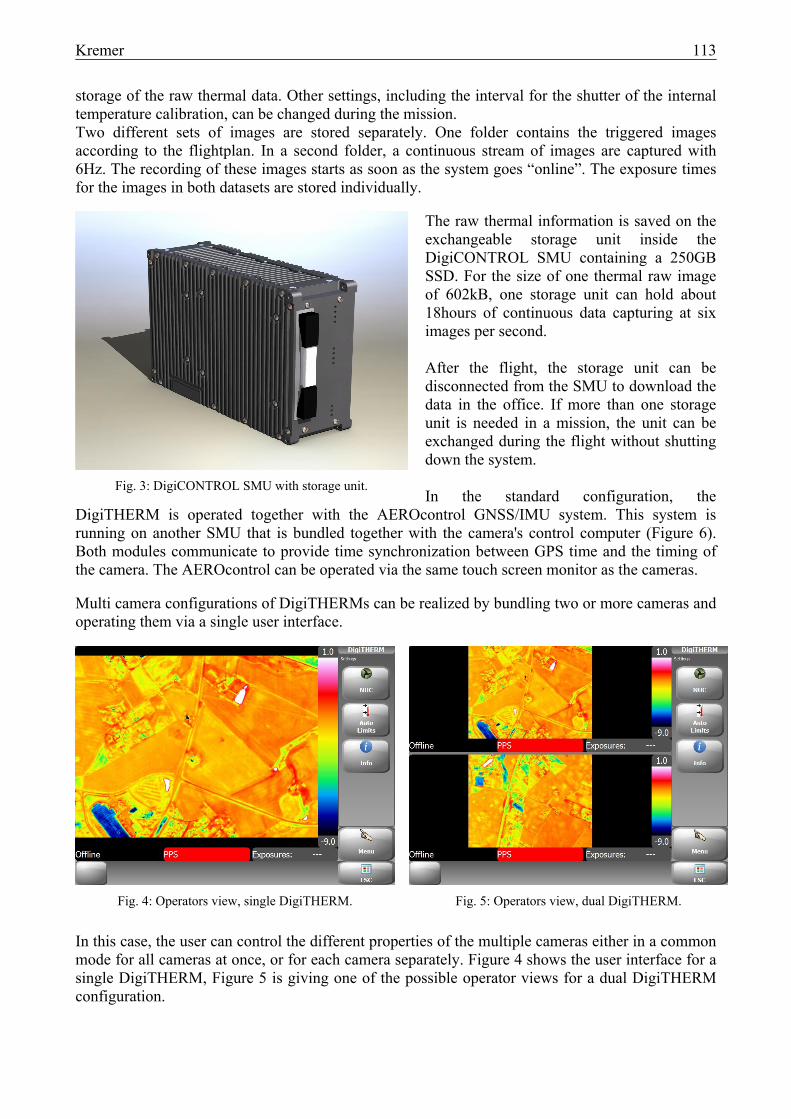
Fig. 4: Operators view, single DigiTHERM. Fig. 5: Operators view, dual DigiTHERM.
In this case, the user can control the different properties of the multiple cameras either in a common mode for all cameras at once, or for each camera separately. Figure 4 shows the user interface for a single DigiTHERM, Figure 5 is giving one of the possible operator views for a dual DigiTHERM configuration.
Fig. 3: DigiCONTROL SMU with storage unit.

114 Kremer
2.3. Multi Sensor Systems
The DigiTHERM is operated with the same DigiCONTROL SMU using the same storage units as the DigiCAM (VIS) medium format digital camera. Switching of the SMU from a DigiTHERM to a DigiCAM and vice versa is possible.
Fig. 6: DigiCONTROL SMU bundled with AEROcontrol SMU and IMU-IIe.
Different combinations of DigiTHERMs and DigiCAMs can be operated and controlled via one user interface. The single sensors are bundled to groups in order to allow adjusting common settings of one group of sensors at once. During operation, the exposure times of the ThIR or VIS images are stored for the determination of the position and attitude at the instant of exposure employing the AEROcontrol GNSS/IMU system. As long as the different cameras are mounted rigidly on one platform, an arbitrary number of cameras can be georeferenced with one AEROcontrol. Figure 7 shows a multi sensor system consisting of a LiteMapper laser scanner, a DigiCAM and a DigiTHERM. All sensors are georeferenced via one AEROcontrol IMU-IId. Fig. 7: Multisensor System constisting of a laserscanner, a thermal
camera, a VIS camera and IMU.
Kremer 115
3. PROJECT EXAMPLE
Between the 22nd and the 30th January 2009, the French city of Montpellier was photographed on behalf of the city council of Montepellier with thermal images of about 75cm GSD by INTERATLAS, Clamart, France. The four flight missions covered an area of 685km2 with 13500 images. All thermal images were taken in the night and in the early morning before sunrise.
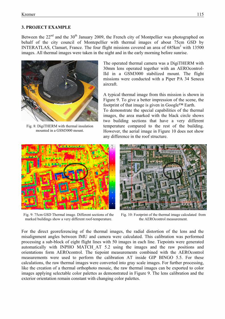
The operated thermal camera was a DigiTHERM with 30mm lens operated together with an AEROcontrol-IId in a GSM3000 stabilized mount. The flight missions were conducted with a Piper PA 34 Seneca aircraft. A typical thermal image from this mission is shown in Figure 9. To give a better impression of the scene, the footprint of that image is given in Google™ Earth. To demonstrate the special capabilities of the thermal images, the area marked with the black circle shows two building sections that have a very different temperature compared to the rest of the building. However, the aerial image in Figure 10 does not show any difference in the roof structure.
Fig. 9: 75cm GSD Thermal image. Different sections of the marked buildings show a very different roof-temperature.
Fig. 10: Footprint of the thermal image calculated from the AEROcontrol measurement.
For the direct georeferencing of the thermal images, the radial distortion of the lens and the misalignment angles between IMU and camera were calculated. This calibration was performed processing a sub-block of eight flight lines with 50 images in each line. Tiepoints were generated automatically with INPHO MATCH_AT 5.2 using the images and the raw positions and orientations form AEROcontrol. The tiepoint measurements combined with the AEROcontrol measurements were used to perform the calibration AT inside GIP BINGO 5.5. For these calculations, the raw thermal images were converted into gray scale images. For further processing, like the creation of a thermal orthophoto mosaic, the raw thermal images can be exported to color images applying selectable color palettes as demonstrated in Figure 9. The lens calibration and the exterior orientation remain constant with changing color palettes.
Fig. 8: DigiTHERM with thermal insulation mounted in a GSM3000 mount.
116 Kremer
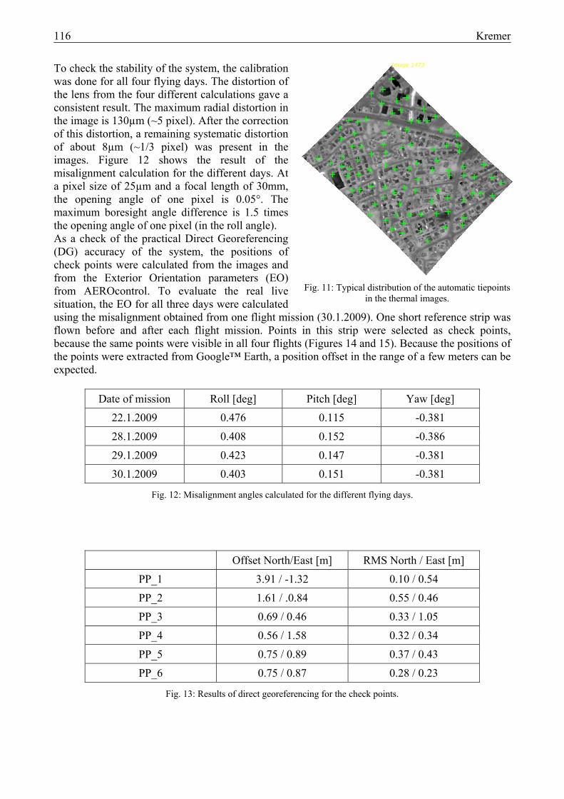
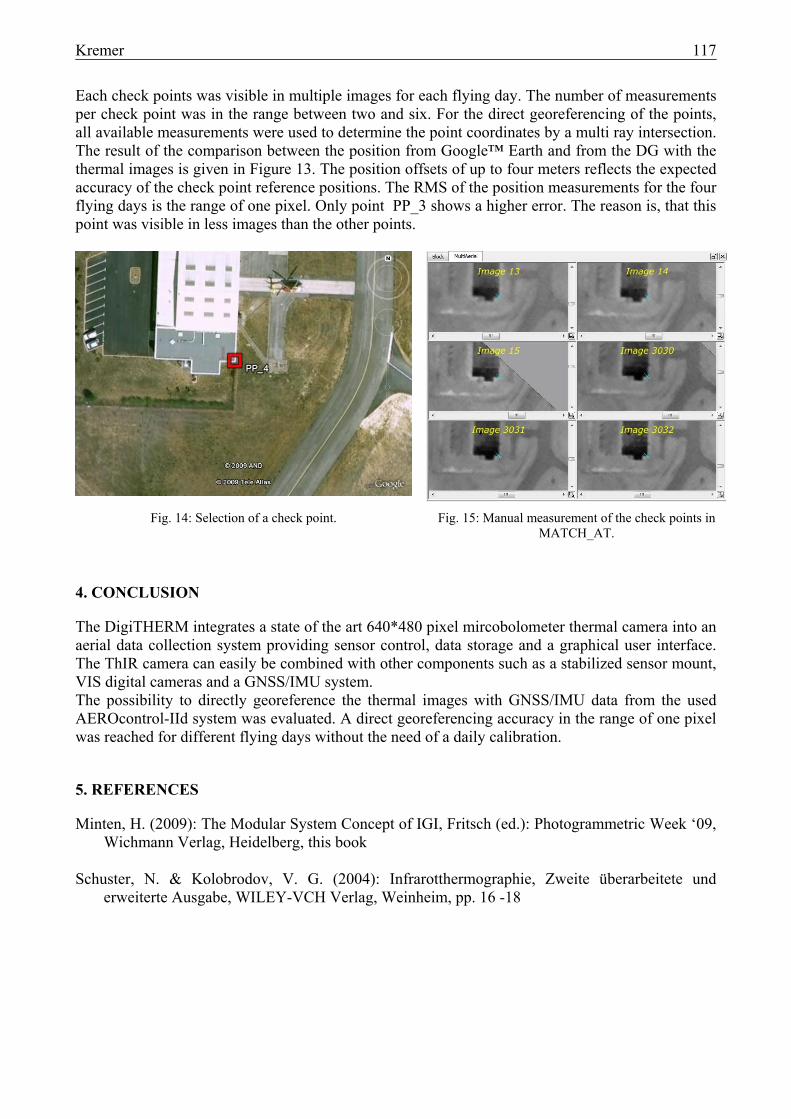
To check the stability of the system, the calibration was done for all four flying days. The distortion of the lens from the four different calculations gave a consistent result. The maximum radial distortion in the image is 130µm (~5 pixel). After the correction of this distortion, a remaining systematic distortion of about 8µm (~1/3 pixel) was present in the images. Figure 12 shows the result of the misalignment calculation for the different days. At a pixel size of 25µm and a focal length of 30mm, the opening angle of one pixel is 0.05°. The maximum boresight angle difference is 1.5 times the opening angle of one pixel (in the roll angle). As a check of the practical Direct Georeferencing (DG) accuracy of the system, the positions of check points were calculated from the images and from the Exterior Orientation parameters (EO) from AEROcontrol. To evaluate the real live situation, the EO for all three days were calculated using the misalignment obtained from one flight mission (30.1.2009). One short reference strip was flown before and after each flight mission. Points in this strip were selected as check points, because the same points were visible in all four flights (Figures 14 and 15). Because the positions of the points were extracted from Google™ Earth, a position offset in the range of a few meters can be expected.
Date of mission Roll [deg] Pitch [deg] Yaw [deg]
22.1.2009 0.476 0.115 -0.381
28.1.2009 0.408 0.152 -0.386
29.1.2009 0.423 0.147 -0.381
30.1.2009 0.403 0.151 -0.381
Fig. 12: Misalignment angles calculated for the different flying days.
Offset North/East [m] RMS North / East [m]
PP_1 3.91 / -1.32 0.10 / 0.54
PP_2 1.61 / .0.84 0.55 / 0.46
PP_3 0.69 / 0.46 0.33 / 1.05
PP_4 0.56 / 1.58 0.32 / 0.34
PP_5 0.75 / 0.89 0.37 / 0.43
PP_6 0.75 / 0.87 0.28 / 0.23
Fig. 13: Results of direct georeferencing for the check points.
Fig. 11: Typical distribution of the automatic tiepoints in the thermal images.
Kremer 117
Each check points was visible in multiple images for each flying day. The number of measurements per check point was in the range between two and six. For the direct georeferencing of the points, all available measurements were used to determine the point coordinates by a multi ray intersection. The result of the comparison between the position from Google™ Earth and from the DG with the thermal images is given in Figure 13. The position offsets of up to four meters reflects the expected accuracy of the check point reference positions. The RMS of the position measurements for the four flying days is the range of one pixel. Only point PP_3 shows a higher error. The reason is, that this point was visible in less images than the other points.
Fig. 14: Selection of a check point. Fig. 15: Manual measurement of the check points in MATCH_AT.
4. CONCLUSION
The DigiTHERM integrates a state of the art 640*480 pixel mircobolometer thermal camera into an aerial data collection system providing sensor control, data storage and a graphical user interface. The ThIR camera can easily be combined with other components such as a stabilized sensor mount, VIS digital cameras and a GNSS/IMU system. The possibility to directly georeference the thermal images with GNSS/IMU data from the used AEROcontrol-IId system was evaluated. A direct georeferencing accuracy in the range of one pixel was reached for different flying days without the need of a daily calibration.
5. REFERENCES
Minten, H. (2009): The Modular System Concept of IGI, Fritsch (ed.): Photogrammetric Week ‘09, Wichmann Verlag, Heidelberg, this book
Schuster, N. & Kolobrodov, V. G. (2004): Infrarotthermographie, Zweite überarbeitete und
erweiterte Ausgabe, WILEY-VCH Verlag, Weinheim, pp. 16 -18