optimizing the use of in situ rock in underground...
TRANSCRIPT

Optimizing the Use of in situ Rock in Underground Powerhouses
217
OPTIMIZING THE USE OF IN SITU ROCK IN UNDERGROUND POWERHOUSES
V.V. Badareenarayana Head, Hydro-Civil Designs, Energy Infratech Private Limited, 145-146 Udyog Vihar, Phase-IV, Gurgaon–122 015, India. E-mail: [email protected] R. Venugopala Rao
General Manager, Energy Infratech Private Limited, 145-146 Udyog Vihar, Phase-IV, Gurgaon–122 015, India. E-mail: [email protected]
ABSTRACT: All the surface as well as underground hydropower stations invariably have Electrical Overhead Travelling (EOT) cranes to facilitate erection and maintenance of the generating equipment. In our country, the system of columns and beams alongside the longitudinal walls is generally adopted till recently, to facilitate movement of the crane, even in under- ground powerhouses. In the advanced countries, the commonly adopted practice is to utilize rock walls of the powerhouse cavern and dispense with building of separate columns. Such a design will reduce the time and cost of building underground powerhouses. Even though the provision of running the cranes on rock supports has been adopted in a few small size powerhouses in the south, where the rocks are geo-technically superior, similar attempts were not made in the northern part of India till recently. Such a design is successfully implemented for the first time in the Himalayan Geology while building a 100 MW capacity underground powerhouse on the Malana river in Himachal Pradesh. Various options available to use the in-situ rock for supporting the crane rails are described, with their respective merits and demerits. The system adopted for the said powerhouse, designed by the authors, is described in greater detail. Investigations and analysis conducted for designing the rock support system, as well as the special care taken to make the design into a successful reality, are briefly described. 1. INTRODUCTION
Underground hydropower stations are becoming very common, as they provide the advantages of minimizing the length of water conductor and optimum utilization of the available generation head. Nearly 30 powerhouses of the underground type are already in operation in the country, and about 10 more are under construction, whereas many more are in the planning stage.
Design and construction of large underground openings involve consideration of the following aspects. • Geological and geo-technical investigations • Stress analysis • Study of structurally controlled instabilities • Design of rock support system • Appropriate excavation pattern and blasting technique • Evaluation and monitoring of ground movements
2. PROVISION OF EOT CRANES
Electrically operated overhead travelling cranes are invariably provided in hydro power stations to facilitate erection and maintenance of the various electro mechanical equipments. In the powerhouses built over ground, such cranes run on column and beam frames, provided for supporting the roof structure. However, in the case of underground powerhouses, built in rock caverns, advantage can be taken by utilizing the
in situ rock walls to support the crane rails. This not only saves the construction of separate column and beam facility, but also allows early erection of the crane.
3. METHODS OF CRANE SUPPORTING
The most commonly used methods for supporting the crane rails in underground powerhouses are: • Building rock bolted, reinforced concrete beams along
the powerhouse long walls. • Providing a bench/ledge of suitable width along the walls.
These arrangements are shown in Figure 1.
Both the methods have their own design considerations and advantages, and it is up to the designer to choose any one of these. Width of the powerhouse cavern is determined by the type and size of machines used and their layout arrangement together with the auxiliaries, and the width is fixed for the given requirements. The rock bolted beams to support the crane are constructed with projection from the rock walls, and therefore the center to center distance between the crane rails is smaller than the cavern width. On the other hand, the rock ledge on each wall will be provided beyond the wall face, and therefore the span of the crane will be larger than the cavern width. This in turn increases the span of the roof arch of the powerhouse cavern. It is simpler to make the rock ledge as it does not involve any concrete construction during rock
IGC 2009, Guntur, INDIA

Optimizing the Use of in situ Rock in Underground Powerhouses
218
excavation. Extra care is needed to attain proper and accurate shape in the excavated rock to act as an elastic foundation to the RCC beam, or to provide proper rock bench for carrying the crane loads. Design approaches for both the arrangements are briefly described in the subsequent paragraphs. The author’s preference would, however, be to go for a rock ledge option.
(a) Crane on Column and Beam
(b) Rock Bolted Crane Beam
(c) Crane on Rock Ledge
Fig. 1: Crane Supporting Methods in Underground Power House
Stability of rock ledge or rock bolted beam in an underground powerhouse depends on rock wall stability, which in turn depends on the cavern span and the geologic conditions. Lateral openings like the access tunnel or bus duct galleries, if placed close to the rock ledge/beam may affect the stability of these, for which special measures with provision of suitable column supports may be necessary.
3.1 Rock-Bolted Crane Beam
The design of a rock bolted crane beam is carried out either by the method of grid beams or by the method of beam on elastic foundation, but the later method is commonly used. Cross sectional dimensions of the beam are determined according to the wheel loads and horizontal braking forces from the crane. Usually 3 rows of rock bolts are provided, the upper 2 rows are tension bolts and the lower row is of compression bolts. The bolts are chosen between 20 mm and 36 mm in diameter, with lengths varying from 6 m to 8 m,
and are usually spaced at 0.7 m to 1.0 m intervals. Typical section of a rock bolted crane beam built for the Guang Zhou power station in China is shown in Figure 2. The beams were designed to carry two overhead travelling cranes, each of 200T capacity with 19.5 m span (Guan Peiwn & Han Zhihong 1992).
Fig. 2: Typical Rock Ledge at Guang Zhou Power
Station in China
3.2 Rock-Ledge Crane Support
In the case of rock ledge type design, the vertical as well as horizontal loads from the crane wheels are directly transmitted to the rock mass below the ledge. Therefore the design involves determining the amount of rock reinforcement required to ensure that adequate factor of safety is available against shear failure along the weakest plane. Like in the rock bolted beam, 3 rows of rock bolts are provided below the bench. The top 2 rows of bolts are placed with upward inclination and designed for tensile force, where as the bottom row will comprise of compression bolts and are placed with a downward inclination. Size, length and spacing of these bolts depend upon the crane loads and the rock conditions. Such rock reinforcement in the rock ledge area is in addition to the pattern rock bolts needed to support the cavern walls. The width of rock ledge is suitably chosen to keep a minimum distance of 500 mm between the center line of crane rail and the rock wall face below the ledge. Minimum clearance from the crane rail to the rock face above the ledge, as required for the crane operation shall also be provided. Concrete base of minimum 500 mm thickness is provided above the rock ledge, to act as crane support. It is a better practice to provide steel reinforcement in the base concrete in order to take care of any differential deformations due to varying rock conditions. Typical arrangement of a crane-supporting rock ledge is shown in Figure 3.
4. THE CASE STUDY
4.1 About the Project
The Malana-II HE project, currently under construction, is situated immediately upstream of the existing Malana-I HE Project in the state of Himachal Pradesh, on the Malana river,

Optimizing the Use of in situ Rock in Underground Powerhouses
219
a tributary of the Parvati river, which itself is a tributary to the Beas river. The underground powerhouse, equipped with 2 units of 50 MW each, is in advanced stage of completion. The machine hall cavern excavated in Manikaran quartzites, has overall dimensions of 50 m (L), 17.5 m (W) and 40 m (H). Center line of the turbines is kept at El. 1919.4 m, whereas the service bay elevation is 1929.6 m. One EOT crane of 130T/25T capacity is provided to facilitate erection and maintenance of the generation equipment. The crane rail elevation is fixed at 1940.25 m. Initially the crane was proposed to be mounted on RCC column and beam frames constructed along both the longitudinal walls, with a span of 16 m between the crane rails. The design has been changed to place the crane rails on rock ledges on both sides.
Fig. 3: Typical Rock Ledge
4.2 Rock Ledge Design
Minimum width of the rock ledges has been worked out as 1.25 m to keep clear distances of 0.5 m and 0.75 m from the center line of rails towards inside and outside respectively. The new arrangement necessitated increase in the crane span from 16 m to 18.5 m. Attempts were made to increase the ledge width towards inside and provide more lateral rock cover from crane rails, thus increasing the strength and stability of the crane supporting ledges. The overall width of 17.5 m is needed mainly below the generator floor for accommodating various generation equipments and their accessories, and it was found possible to reduce the cavern width above this level, to certain extent. Accordingly the width of rock ledges has been increased to 2.0 m by moving the inner edges by 0.75 m, making the clear width of cavern at this level as 16 m. The full width of 17.5 m has been restored at a level 5 m below the ledge, corresponding to the top of bus duct. Special care has been taken to achieve accurate shape of the ledge, by resorting to pre-spitting and smooth wall blasting. The rock face was protected with shotcrete and spot rock bolts as required, immediately after excavation. Construction details of the crane supporting rock ledges provided in the Malana-II powerhouse are shown in Figure 4.
Fig. 4: Crane Supporting Rock Ledge in
Malana-II Power House
4.3 Analysis of Rock Cavern
Three dimensional discontinuum modeling was done using three dimensional distinct element code (3DEC version 3.0, Itasca Conulting group, USA) to understand the rock mass behavior, and stresses in and around the powerhouse openings. A large size model of 200 m × 200 m × 150 m with boundaries placed at sufficiently large distance from the excavations was used for simulation. Actual geometry of machine hall cavern, transformer cavern, bus duct gallery, and all other openings were simulated. All the discontinuities were simulated explicitly and the blocks so formed by cutting the model with joints, were discretized for stress computation. The excavation sequence as planned was also simulated. Based on the results of stress analysis, rock bolts of 7 m in the roof and 8 m in the walls were used. Total surface displacement of 110 mm was predicted at EL 1920 level and 80 mm at EL 1941 level.
4.4 Monitoring of Behavior
Three sections, at RD 11, RD 38 and RD 53 were identified, where maximum movements are expected. These sections were instrumented using 10 m long multipoint borehole extensor- meters on both walls at EL 1943. These extensometers could be read manually, until they were accessible during excavation up to certain level only. Optical deformation monitoring system was used to monitor deformations continuously during further excavation and afterwards. Rock movements were found to disappear after a period of time, as could be seen from the results shown in Figures 5 and 6. As seen from Figure 5, a displacement of 45 mm was recorded on right wall. The measured displacement matched well with the predicted movement of 40 mm after installing the instrument (half of predicted total displacement).
4.5 Load Testing and Result
The efforts resulted in a very successful end product and helped in completely eliminating the provision of columns
Optimizing the Use of in situ Rock in Underground Powerhouses
220
and beams for supporting the EOT crane. The rock ledges were found to safely take the designed as well as excessive crane loads, when the crane was tested under full load and overload conditions.
Fig. 5: Right Wall Movement at EL. 1941 near
Rock Ledge
Fig. 6: Left Wall Movement at EL. 1941 near
Rock Ledge
5. FURTHER APPLICATION
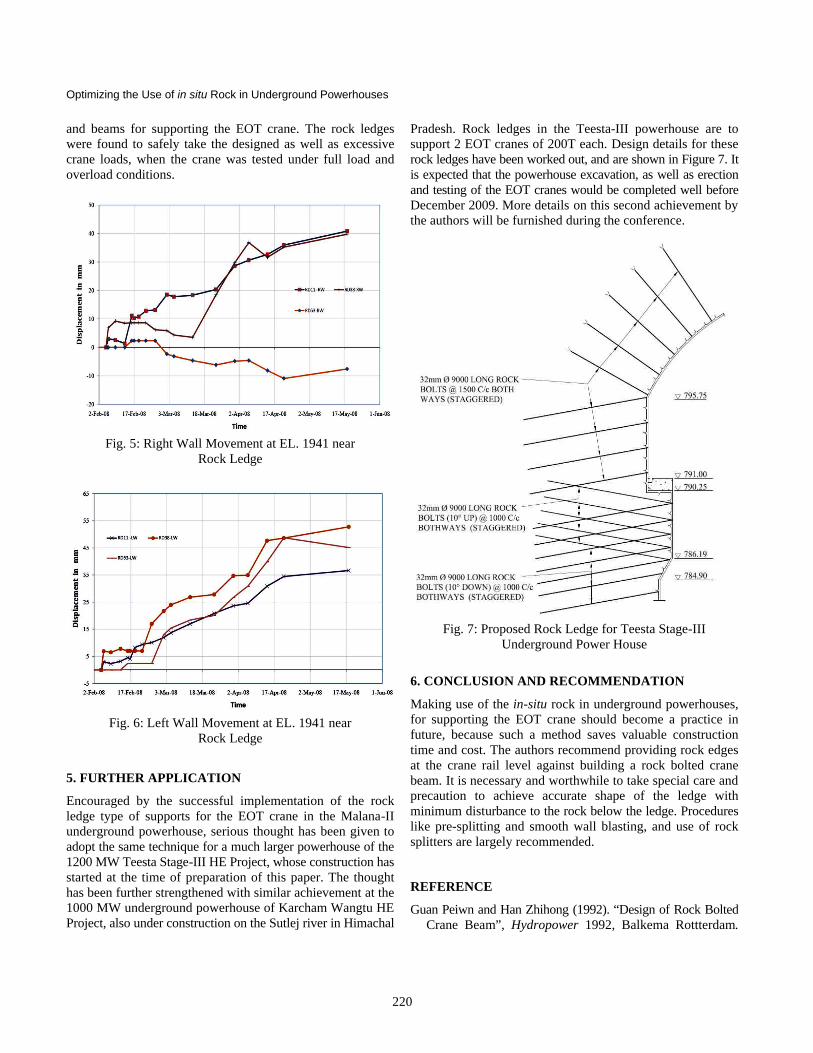
Encouraged by the successful implementation of the rock ledge type of supports for the EOT crane in the Malana-II underground powerhouse, serious thought has been given to adopt the same technique for a much larger powerhouse of the 1200 MW Teesta Stage-III HE Project, whose construction has started at the time of preparation of this paper. The thought has been further strengthened with similar achievement at the 1000 MW underground powerhouse of Karcham Wangtu HE Project, also under construction on the Sutlej river in Himachal
Pradesh. Rock ledges in the Teesta-III powerhouse are to support 2 EOT cranes of 200T each. Design details for these rock ledges have been worked out, and are shown in Figure 7. It is expected that the powerhouse excavation, as well as erection and testing of the EOT cranes would be completed well before December 2009. More details on this second achievement by the authors will be furnished during the conference.
Fig. 7: Proposed Rock Ledge for Teesta Stage-III
Underground Power House
6. CONCLUSION AND RECOMMENDATION
Making use of the in-situ rock in underground powerhouses, for supporting the EOT crane should become a practice in future, because such a method saves valuable construction time and cost. The authors recommend providing rock edges at the crane rail level against building a rock bolted crane beam. It is necessary and worthwhile to take special care and precaution to achieve accurate shape of the ledge with minimum disturbance to the rock below the ledge. Procedures like pre-splitting and smooth wall blasting, and use of rock splitters are largely recommended.
REFERENCE
Guan Peiwn and Han Zhihong (1992). “Design of Rock Bolted Crane Beam”, Hydropower 1992, Balkema Rottterdam.