or describing simultaneous roll, pitch and yawdynlab.mpe.nus.edu.sg/mpelsb/me4241/l6n.pdf · or...
TRANSCRIPT
G. Leng, Flight Dynamics, Stability & Control
Lecture 6 : Aircraft orientation in 3 dimensions
Or describing simultaneous roll, pitch and yaw

G. Leng, Flight Dynamics, Stability & Control
1.0 Flight Dynamics Model
• For flight dynamics & control, the reference frame is
aligned with the aircraft and moves with it. (Why?)
Yb
Xb
Zb Question: Where’s the origin located
for this body axes ?
G. Leng, Flight Dynamics, Stability & Control
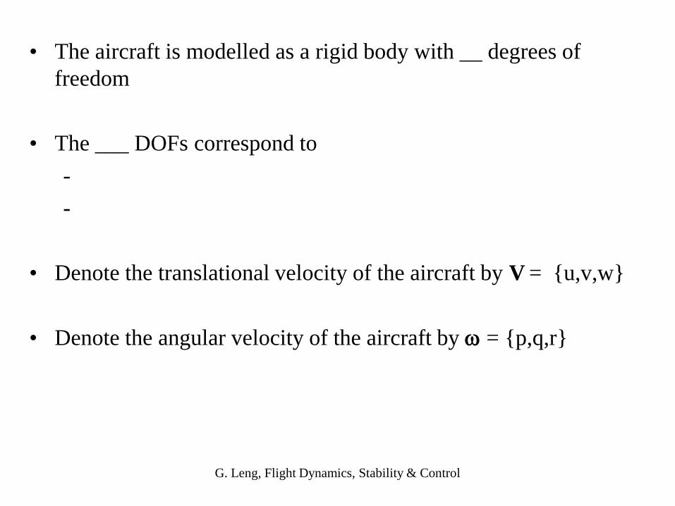
• The aircraft is modelled as a rigid body with __ degrees of
freedom
• The ___ DOFs correspond to
-
-
• Denote the translational velocity of the aircraft by V = {u,v,w}
• Denote the angular velocity of the aircraft by = {p,q,r}
G. Leng, Flight Dynamics, Stability & Control
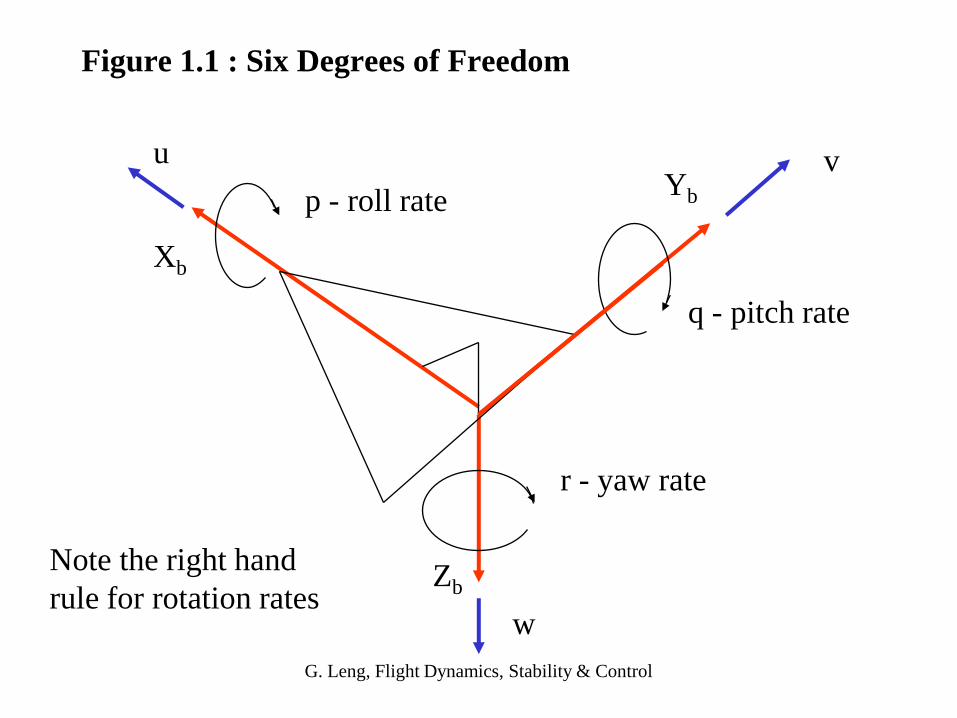
Figure 1.1 : Six Degrees of Freedom
u v
w
p - roll rate
q - pitch rate
r - yaw rate
Xb
Yb
ZbNote the right hand
rule for rotation rates

G. Leng, Flight Dynamics, Stability & Control
1.1 Defining the aircraft orientation - Euler angles
K
J
I
k
j
i
Earth fixed axes
local horizon axes
body axes
I
JK
The local horizon axes is aligned with the Earth fixed axes but
translated to the aircraft’s cg.

G. Leng, Flight Dynamics, Stability & Control
Question : How do we express the basis vectors IJK of the
local horizon system in terms of the basis vectors ijk of the
body axes system or vice versa ?
KJ
I
k
j
i

G. Leng, Flight Dynamics, Stability & Control
Yaw Euler angle (Greek : psi)
Pitch Euler angle (theta)
Roll Euler angle (phi)
The local horizon axes system IJK can be rotated to coincide with
the body axes i j k by using three rotation angles or Euler angles
NB : The order of the rotations is important !
G. Leng, Flight Dynamics, Stability & Control
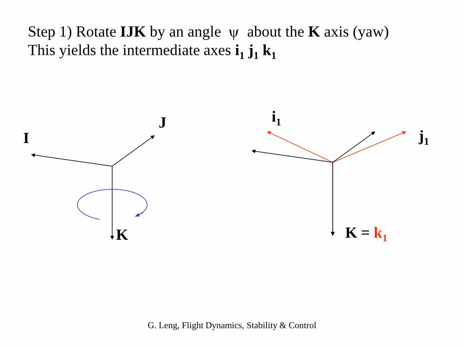
Step 1) Rotate IJK by an angle about the K axis (yaw)
This yields the intermediate axes i1 j1 k1
K
JI j1
i1
K = k1
G. Leng, Flight Dynamics, Stability & Control
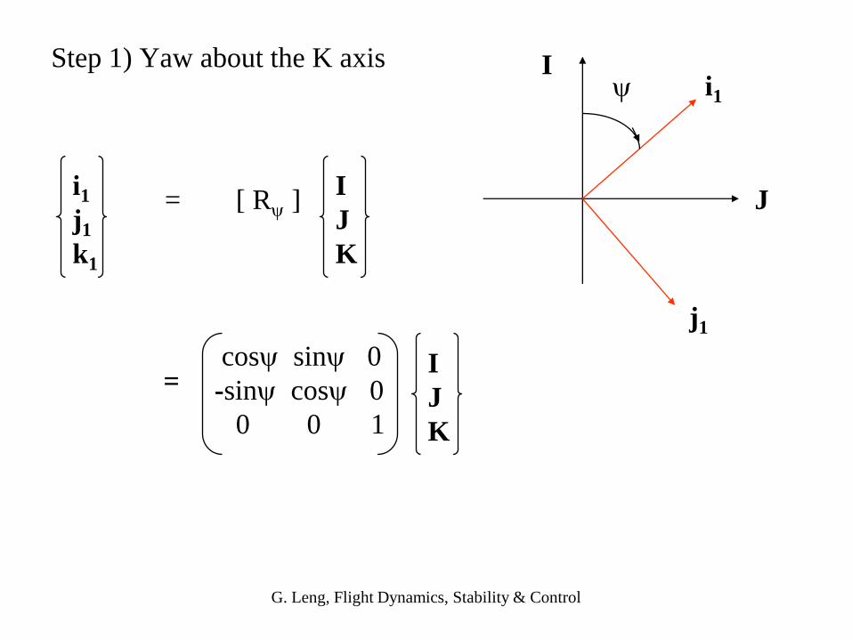
Step 1) Yaw about the K axis
= [ R ]
I
J
i1
j1
i1
j1
k1
I
J
K
cos sin 0
-sin cos 0
0 0 1
=I
J
K

G. Leng, Flight Dynamics, Stability & Control
Step 2) Rotate i1 j1 k1 by an angle about the j1 axis (pitch)
This yields the intermediate axes i2 j2 k2
j1i1
k1
i2
k2
j1 = j2i1
k1

G. Leng, Flight Dynamics, Stability & Control
Step 2) Pitch about the j1 axis
= [ R ]
k1
i1
i2
k2
i2
j2
k2
i1
j1
k1
=i1
j1
k1
cos 0 -sin
0 1 0
sin 0 cos

G. Leng, Flight Dynamics, Stability & Control
j2
i2
k2
Step 3) Rotate i2 j2 k2 by an angle about the new i2 axis (roll)
This yields the body axes i j k
j
k
j2
i2 = i
k2

G. Leng, Flight Dynamics, Stability & Control
Step 3) Roll about the i2 axis
= [ R ]
k2
j2
k j
i
j
k
i2
j2
k2
=i2
j2
k2
1 0 0
0 cos sin
0 -sin cos
G. Leng, Flight Dynamics, Stability & Control
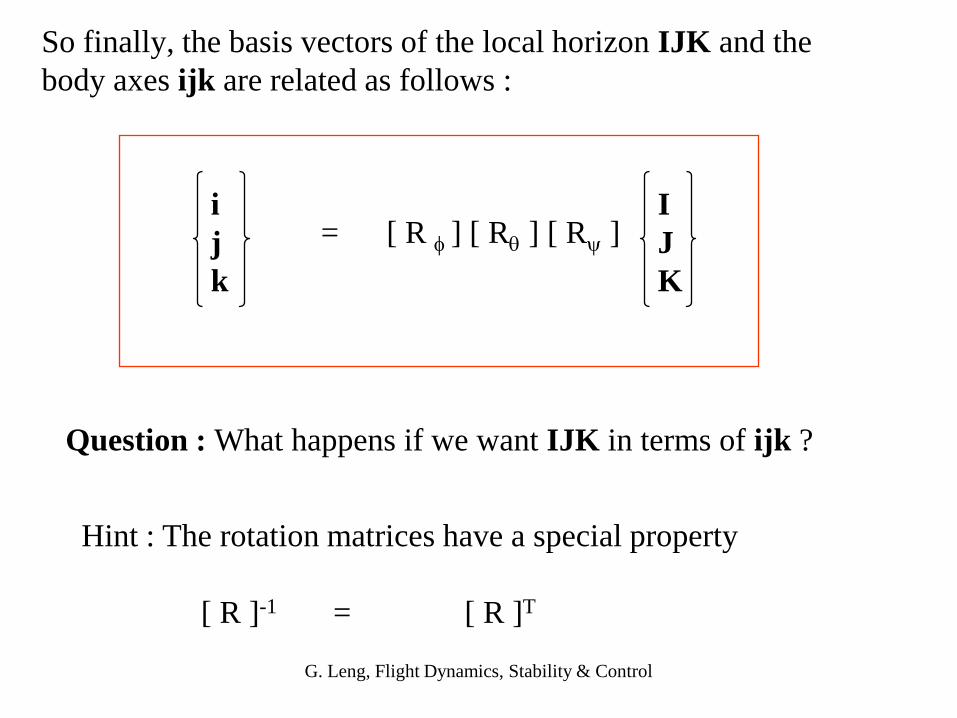
So finally, the basis vectors of the local horizon IJK and the
body axes ijk are related as follows :
i
j
k
= [ R ] [ R ] [ R ]I
J
K
Hint : The rotation matrices have a special property
[ R ]-1 = [ R ]T
Question : What happens if we want IJK in terms of ijk ?
G. Leng, Flight Dynamics, Stability & Control
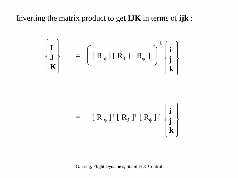
Inverting the matrix product to get IJK in terms of ijk :
I
J
K
= [ R ]T [ R ]T [ R ]Ti
j
k
= [ R ] [ R ] [ R ]i
j
k
-1
G. Leng, Flight Dynamics, Stability & Control
Exercise : Express the weight force component in terms of the
body axes basis vectors i j k
Hint : The weight component points downwards ie W K
hence we need only express K in terms of i j k
G. Leng, Flight Dynamics, Stability & Control
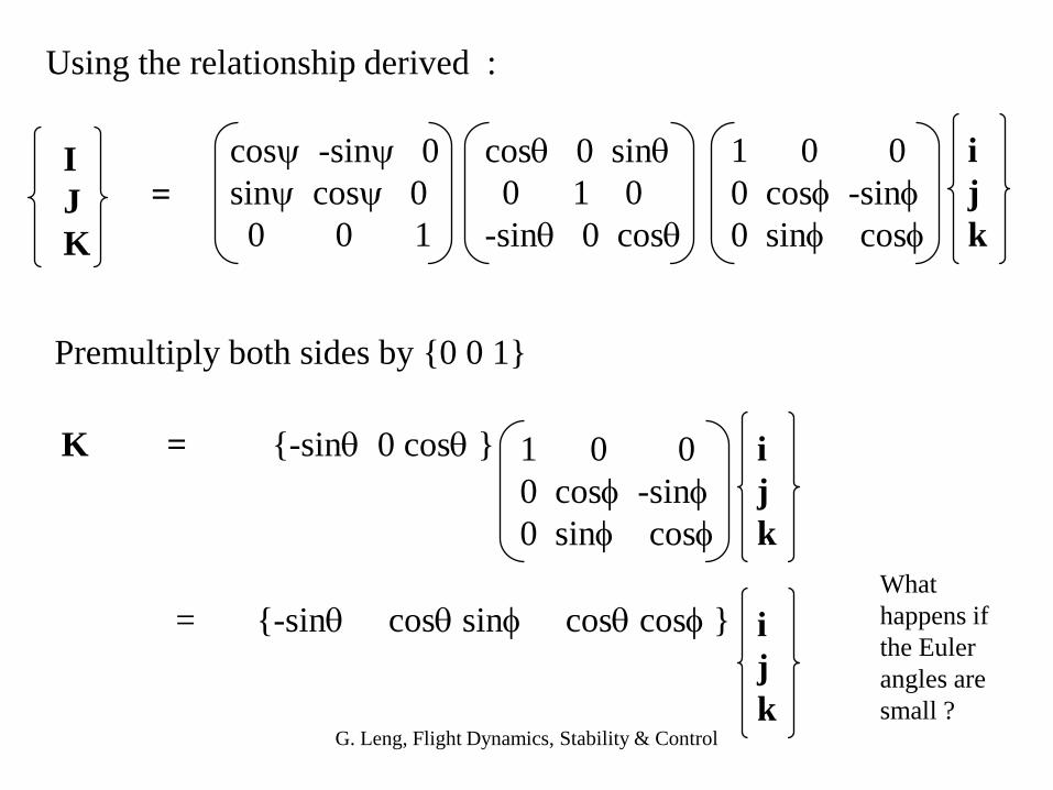
Using the relationship derived :
cos -sin 0
sin cos 0
0 0 1
cos 0 sin
0 1 0
-sin 0 cos
1 0 0
0 cos -sin
0 sin cos
I
J
K
i
j
k
=
Premultiply both sides by {0 0 1}
K = {-sin 0 cos } 1 0 0
0 cos -sin
0 sin cos
i
j
k
= {-sin cos sin cos cos } i
j
k
What
happens if
the Euler
angles are
small ?
G. Leng, Flight Dynamics, Stability & Control
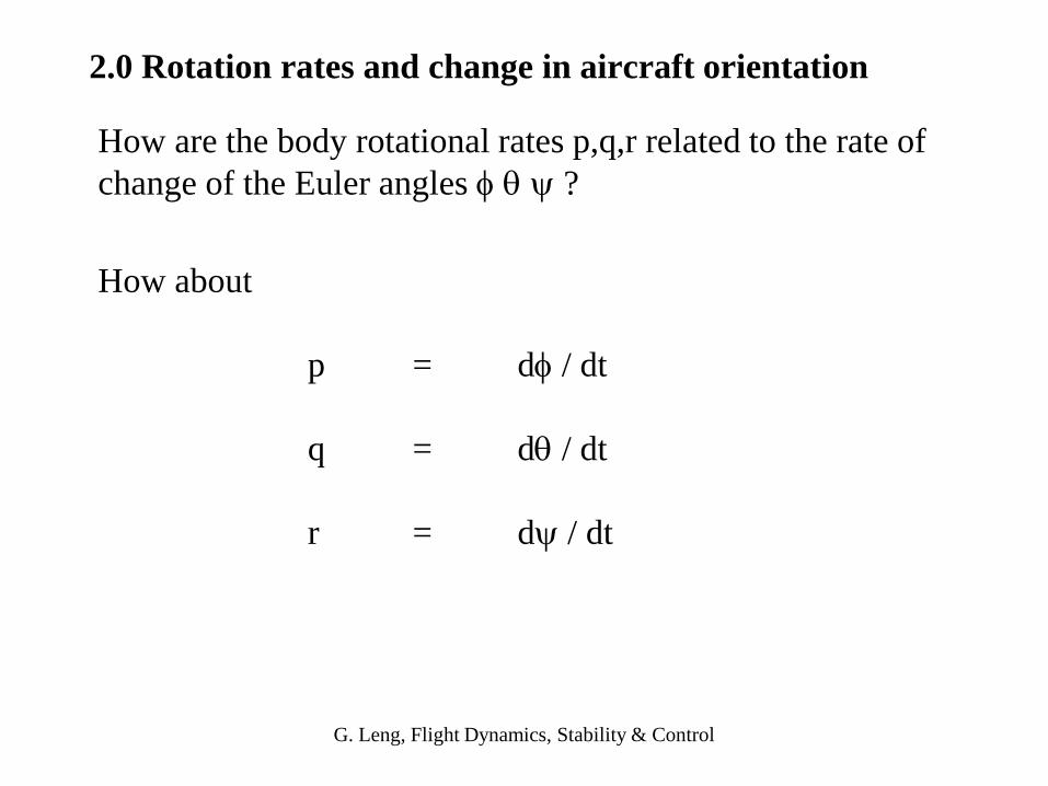
How about
p = d / dt
q = d / dt
r = d / dt
2.0 Rotation rates and change in aircraft orientation
How are the body rotational rates p,q,r related to the rate of
change of the Euler angles ?

G. Leng, Flight Dynamics, Stability & Control
The angular velocity vector is = p i + q j + r k written
using the body axes basis vectors
describes the rate of change in orientation which can also
be written as :
= ’ K + ’ j1 + ’ i2
Noting that
K = -sin i + cos sin j + cos cos k
j1 = j2 = cos j - sin k
i2 = i

G. Leng, Flight Dynamics, Stability & Control
p
q
r=
’
’
’
-sin 0 1
cos sin cos 0
cos cos -sin 0
Inverting yields :
' = p + (q sin + r cos ) tan
' = q cos - r sin
' = (q sin + r cos ) sec
NB : These are the EOMs relating the rate of change of
aircraft orientation to body rotational rates
What
happens if
is 90 o ?
G. Leng, Flight Dynamics, Stability & Control
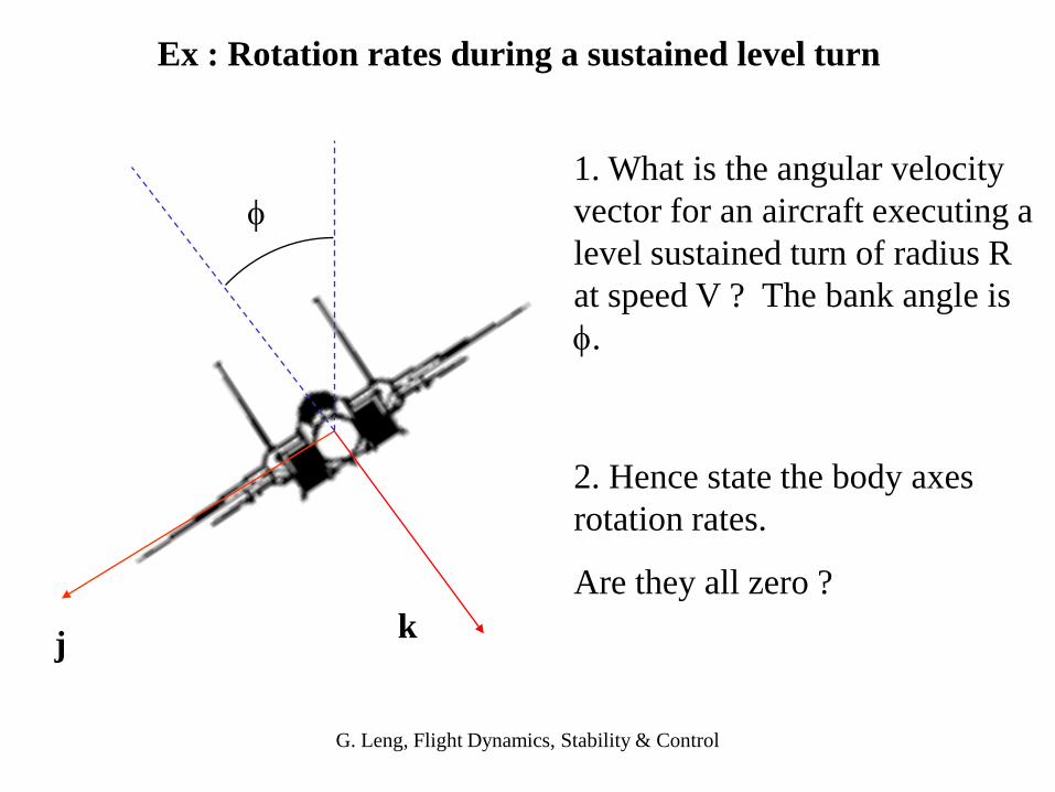
Ex : Rotation rates during a sustained level turn
kj
1. What is the angular velocity
vector for an aircraft executing a
level sustained turn of radius R
at speed V ? The bank angle is
.
2. Hence state the body axes
rotation rates.
Are they all zero ?

G. Leng, Flight Dynamics, Stability & Control
1. The turn rate = V/R
2. Level turn the rotation axis is vertical
3. Hence the angular velocity vector is
= V/R {0, 0, 1} What is ambiguous ?
= V/R K not the body axes k !
So how do we write this in body axes ?

G. Leng, Flight Dynamics, Stability & Control
4. Recall the relationship derived via Euler angles
K = -sin i + cos sin j + cos cos k
Hence in body axes
= V/R(-sin i + cos sin j + cos cos k)
G. Leng, Flight Dynamics, Stability & Control
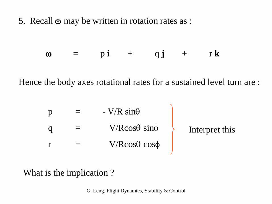
Hence the body axes rotational rates for a sustained level turn are :
p = - V/R sin
q = V/Rcos sin
r = V/Rcos cos
What is the implication ?
5. Recall may be written in rotation rates as :
= p i + q j + r k
Interpret this

G. Leng, Flight Dynamics, Stability & Control
' = p + (q sin + r cos ) tan
' = q cos - r sin
' = (q sin + r cos ) sec
q = V/Rcos sin
r = V/Rcos cos
6. What happens if we substitute these sustained, level turn
rotation rates
in the equations for change in orientation ?
p = - V/R sin
Physically what do you expect?
G. Leng, Flight Dynamics, Stability & Control
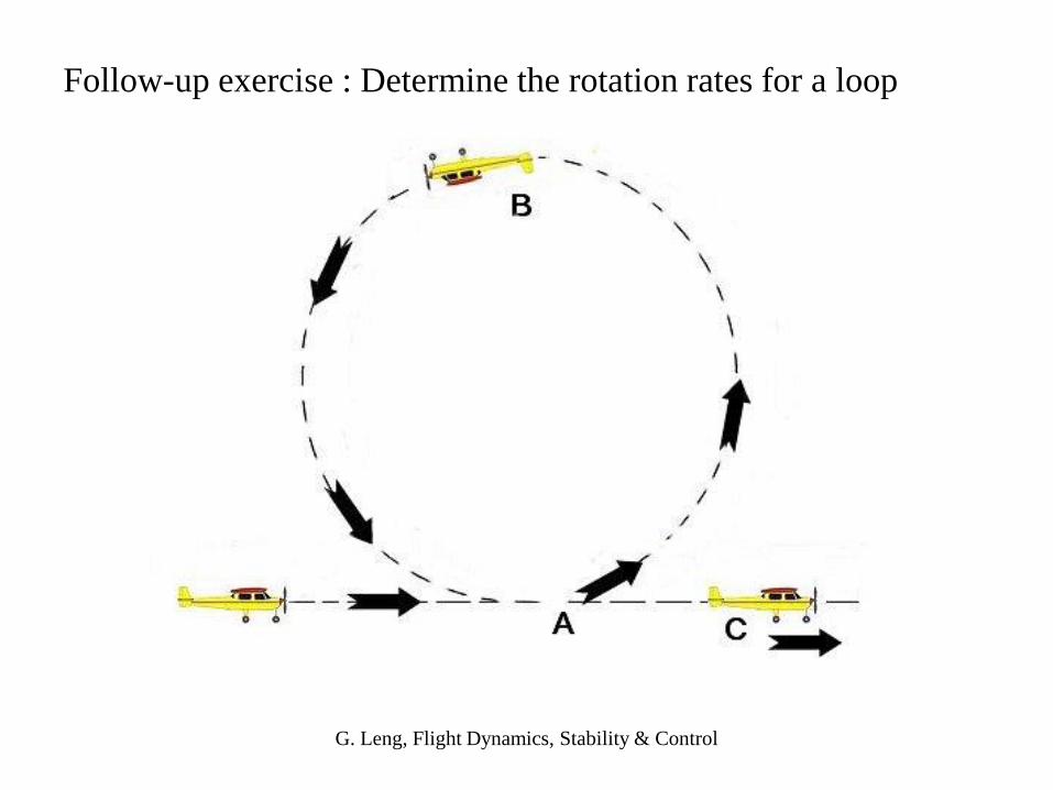
Follow-up exercise : Determine the rotation rates for a loop

G. Leng, Flight Dynamics, Stability & Control
3.0 Aerodynamic forces in the body axes
a
bXb
Yb
Zb
V direction of flight
For a general aircraft orientation, the angle of attack a and
sideslip b are defined as follows:

G. Leng, Flight Dynamics, Stability & Control
3.1 : Writing body velocity components with aerodynamic angles
a
bXb
Yb
Zb
VT
Resolving the velocity vector
u = VT cos b cosa
v = VT sinb
w = VT cosb sina
Question : What about the aerodynamic forces ?
G. Leng, Flight Dynamics, Stability & Control
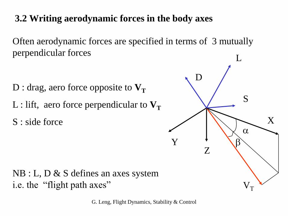
3.2 Writing aerodynamic forces in the body axes
Often aerodynamic forces are specified in terms of 3 mutually
perpendicular forces
D : drag, aero force opposite to VT
L : lift, aero force perpendicular to VT
S : side forcea
b
X
YZ
VT
L
D
S
NB : L, D & S defines an axes system
i.e. the “flight path axes”

G. Leng, Flight Dynamics, Stability & Control
The transformation can be written in terms of two rotations
1) a rotation about the Y body axes by -a
2) a rotation about the resulting Z axis by b
and then inverting the components
D cos(b) sin(b) 0 cos(-a) 0 -sin(-a) X
S = - -sin(b) cos(b) 0 0 1 0 Y
L 0 0 1 sin(-a) 0 cos(-a) Z

G. Leng, Flight Dynamics, Stability & Control
D = - (X cosa + Z sina) cosb - Y sinb
S = (X cosa + Z sina) sinb - Y cosb
L = X sina - Z cosa
Multiplying the rotation matrices yields the body axes components
for the aerodynamic forces
G. Leng, Flight Dynamics, Stability & Control
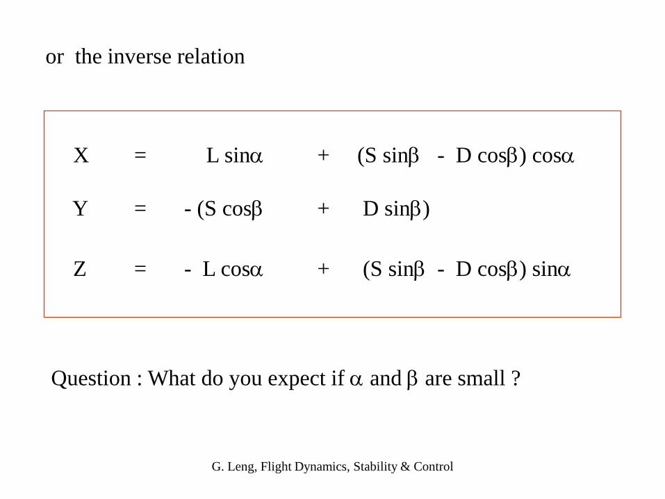
X = L sina + (S sinb - D cosb) cosa
Y = - (S cosb + D sinb)
Z = - L cosa + (S sinb - D cosb) sina
or the inverse relation
Question : What do you expect if a and b are small ?