order no. crt2600 multi-cd control high …diagramas.diagramasde.com/otros/keh-p7015-6015,multi cd...
TRANSCRIPT
CONTENTS
1. SAFETY INFORMATION ............................................2
2. EXPLODED VIEWS AND PARTS LIST .......................2
3. BLOCK DIAGRAM AND SCHEMATIC DIAGRAM .....8
4. PCB CONNECTION DIAGRAM ................................20
5. ELECTRICAL PARTS LIST ........................................28
6. ADJUSTMENT..........................................................32
7. GENERAL INFORMATION .......................................33
7.1 DIAGNOSIS ........................................................33
7.1.1 DISASSEMBLY ..............................................33
7.1.2 CONNECTOR FUNCTION DESCRIPTION ....34
7.2 PARTS .................................................................35
7.2.1 IC ....................................................................35
7.2.2 DISPLAY.........................................................41
7.3 OPERATIONAL FLOW CHART...........................42
8. OPERATIONS AND SPECIFICATIONS.....................43
PIONEER CORPORATION 4-1, Meguro 1-Chome, Meguro-ku, Tokyo 153-8654, Japan PIONEER ELECTRONICS SERVICE INC. P.O.Box 1760, Long Beach, CA 90801-1760 U.S.A.PIONEER EUROPE NV Haven 1087 Keetberglaan 1, 9120 Melsele, Belgium PIONEER ELECTRONICS ASIACENTRE PTE.LTD. 253 Alexandra Road, #04-01, Singapore 159936
C PIONEER CORPORATION 2000 K-ZZU. DEC. 2000 Printed in Japan
ORDER NO.
CRT2600
MULTI-CD CONTROL HIGH POWER CASSETTE PLAYER WITH FM/AM TUNER
KEH-P7015 X1M/ES
ServiceManual
KEH-P7015/X1M/ES
- This service manual should be used together with the following manual(s):Model No. Order No. Mech. Module Remarks
CX-1011 CRT2406 3L Cassette Mech. Module:Mech.Description, Disassembly, Adjustment
KEH-P6015 X1M/ES
NOTE:
- This service manual does not describe the CD test mode.
For the operations in the CD test mode, refer to the CD player's Service manual.
- Extension cable of cassette mechanism : Jig No. GGD1121
2
KEH-P7015,P6015
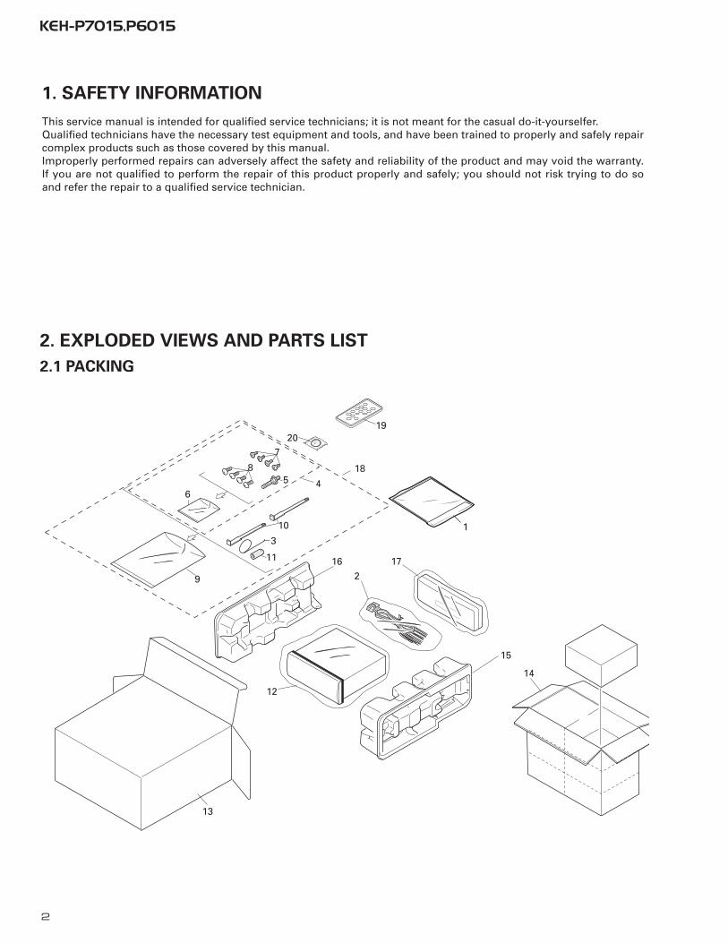
2. EXPLODED VIEWS AND PARTS LIST
2.1 PACKING
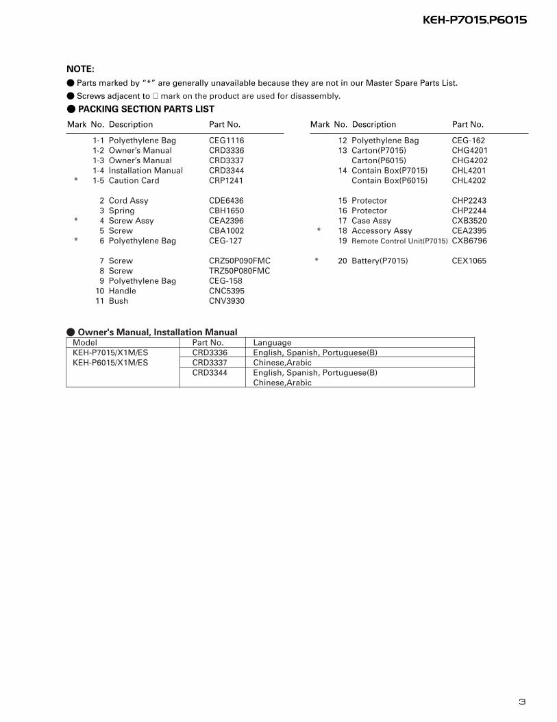
1. SAFETY INFORMATION
This service manual is intended for qualified service technicians; it is not meant for the casual do-it-yourselfer.Qualified technicians have the necessary test equipment and tools, and have been trained to properly and safely repaircomplex products such as those covered by this manual.Improperly performed repairs can adversely affect the safety and reliability of the product and may void the warranty.If you are not qualified to perform the repair of this product properly and safely; you should not risk trying to do soand refer the repair to a qualified service technician.
4
7
11
3
10
9
8
65
162
17
12
15
14
13
1
1920
18
3
KEH-P7015,P6015
Mark No. Description Part No. Mark No. Description Part No.
- PACKING SECTION PARTS LIST
NOTE:
- Parts marked by “*” are generally unavailable because they are not in our Master Spare Parts List.
- Screws adjacent to ∇ mark on the product are used for disassembly.
1-1 Polyethylene Bag CEG11161-2 Owner’s Manual CRD33361-3 Owner’s Manual CRD33371-4 Installation Manual CRD3344
* 1-5 Caution Card CRP1241
2 Cord Assy CDE64363 Spring CBH1650
* 4 Screw Assy CEA23965 Screw CBA1002
* 6 Polyethylene Bag CEG-127
7 Screw CRZ50P090FMC8 Screw TRZ50P080FMC9 Polyethylene Bag CEG-158
10 Handle CNC539511 Bush CNV3930
12 Polyethylene Bag CEG-16213 Carton(P7015) CHG4201
Carton(P6015) CHG420214 Contain Box(P7015) CHL4201
Contain Box(P6015) CHL4202
15 Protector CHP224316 Protector CHP224417 Case Assy CXB3520
* 18 Accessory Assy CEA239519 Remote Control Unit(P7015) CXB6796
* 20 Battery(P7015) CEX1065
- Owner's Manual, Installation ManualModel Part No. LanguageKEH-P7015/X1M/ES CRD3336 English, Spanish, Portuguese(B)KEH-P6015/X1M/ES CRD3337 Chinese,Arabic
CRD3344 English, Spanish, Portuguese(B)Chinese,Arabic

4
KEH-P7015,P6015
2.2 EXTERIOR
A
B
C
5
KEH-P7015,P6015
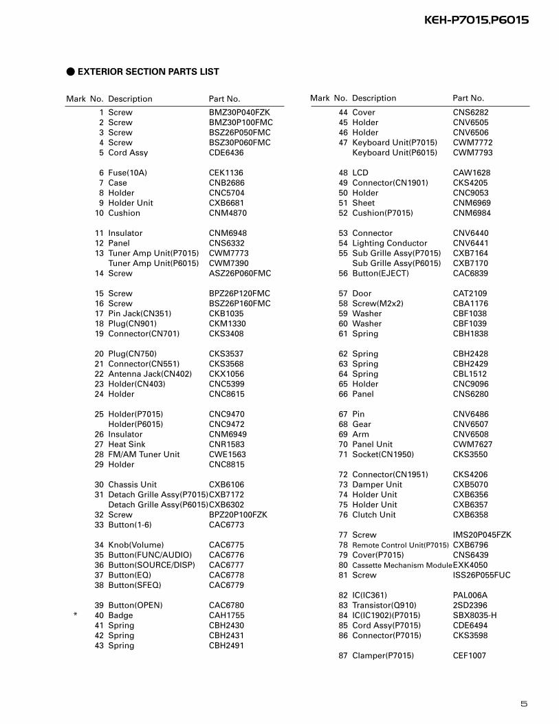
- EXTERIOR SECTION PARTS LIST
Mark No. Description Part No. Mark No. Description Part No.
1 Screw BMZ30P040FZK2 Screw BMZ30P100FMC3 Screw BSZ26P050FMC4 Screw BSZ30P060FMC5 Cord Assy CDE6436
6 Fuse(10A) CEK11367 Case CNB26868 Holder CNC57049 Holder Unit CXB6681
10 Cushion CNM4870
11 Insulator CNM694812 Panel CNS633213 Tuner Amp Unit(P7015) CWM7773
Tuner Amp Unit(P6015) CWM739014 Screw ASZ26P060FMC
15 Screw BPZ26P120FMC16 Screw BSZ26P160FMC17 Pin Jack(CN351) CKB103518 Plug(CN901) CKM133019 Connector(CN701) CKS3408
20 Plug(CN750) CKS353721 Connector(CN551) CKS356822 Antenna Jack(CN402) CKX105623 Holder(CN403) CNC539924 Holder CNC8615
25 Holder(P7015) CNC9470Holder(P6015) CNC9472
26 Insulator CNM694927 Heat Sink CNR158328 FM/AM Tuner Unit CWE156329 Holder CNC8815
30 Chassis Unit CXB610631 Detach Grille Assy(P7015)CXB7172
Detach Grille Assy(P6015)CXB630232 Screw BPZ20P100FZK33 Button(1-6) CAC6773
34 Knob(Volume) CAC677535 Button(FUNC/AUDIO) CAC677636 Button(SOURCE/DISP) CAC677737 Button(EQ) CAC677838 Button(SFEQ) CAC6779
39 Button(OPEN) CAC6780* 40 Badge CAH1755
41 Spring CBH243042 Spring CBH243143 Spring CBH2491
44 Cover CNS628245 Holder CNV650546 Holder CNV650647 Keyboard Unit(P7015) CWM7772
Keyboard Unit(P6015) CWM7793
48 LCD CAW162849 Connector(CN1901) CKS420550 Holder CNC905351 Sheet CNM696952 Cushion(P7015) CNM6984
53 Connector CNV644054 Lighting Conductor CNV644155 Sub Grille Assy(P7015) CXB7164
Sub Grille Assy(P6015) CXB717056 Button(EJECT) CAC6839
57 Door CAT210958 Screw(M2x2) CBA117659 Washer CBF103860 Washer CBF103961 Spring CBH1838
62 Spring CBH242863 Spring CBH242964 Spring CBL151265 Holder CNC909666 Panel CNS6280
67 Pin CNV648668 Gear CNV650769 Arm CNV650870 Panel Unit CWM762771 Socket(CN1950) CKS3550
72 Connector(CN1951) CKS420673 Damper Unit CXB507074 Holder Unit CXB635675 Holder Unit CXB635776 Clutch Unit CXB6358
77 Screw IMS20P045FZK78 Remote Control Unit(P7015) CXB679679 Cover(P7015) CNS643980 Cassette Mechanism ModuleEXK405081 Screw ISS26P055FUC
82 IC(IC361) PAL006A83 Transistor(Q910) 2SD239684 IC(IC1902)(P7015) SBX8035-H85 Cord Assy(P7015) CDE649486 Connector(P7015) CKS3598
87 Clamper(P7015) CEF1007

6
KEH-P7015,P6015
2.3 CASSETTE MECHANISM MODULE
D
E
7
KEH-P7015,P6015
Mark No. Description Part No. Mark No. Description Part No.
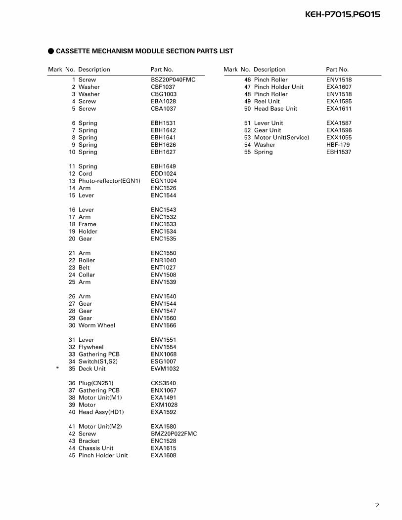
- CASSETTE MECHANISM MODULE SECTION PARTS LIST
1 Screw BSZ20P040FMC2 Washer CBF10373 Washer CBG10034 Screw EBA10285 Screw CBA1037
6 Spring EBH15317 Spring EBH16428 Spring EBH16419 Spring EBH1626
10 Spring EBH1627
11 Spring EBH164912 Cord EDD102413 Photo-reflector(EGN1) EGN100414 Arm ENC152615 Lever ENC1544
16 Lever ENC154317 Arm ENC153218 Frame ENC153319 Holder ENC153420 Gear ENC1535
21 Arm ENC155022 Roller ENR104023 Belt ENT102724 Collar ENV150825 Arm ENV1539
26 Arm ENV154027 Gear ENV154428 Gear ENV154729 Gear ENV156030 Worm Wheel ENV1566
31 Lever ENV155132 Flywheel ENV155433 Gathering PCB ENX106834 Switch(S1,S2) ESG1007
* 35 Deck Unit EWM1032
36 Plug(CN251) CKS354037 Gathering PCB ENX106738 Motor Unit(M1) EXA149139 Motor EXM102840 Head Assy(HD1) EXA1592
41 Motor Unit(M2) EXA158042 Screw BMZ20P022FMC43 Bracket ENC152844 Chassis Unit EXA161545 Pinch Holder Unit EXA1608
46 Pinch Roller ENV151847 Pinch Holder Unit EXA160748 Pinch Roller ENV151849 Reel Unit EXA158550 Head Base Unit EXA1611
51 Lever Unit EXA158752 Gear Unit EXA159653 Motor Unit(Service) EXX105554 Washer HBF-17955 Spring EBH1537
8
KEH-P7015,P60151 2 3 4
1 2 3 4
D
C
B
A
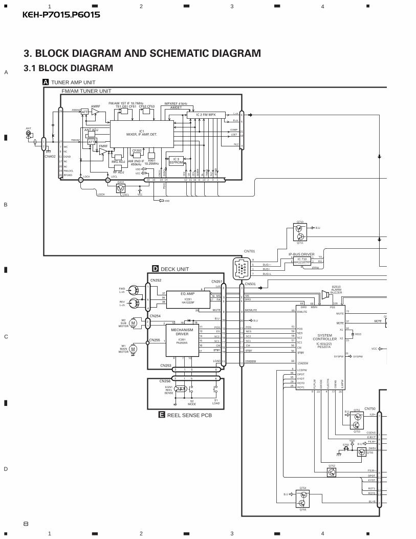
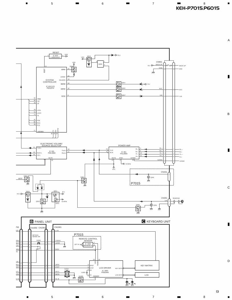
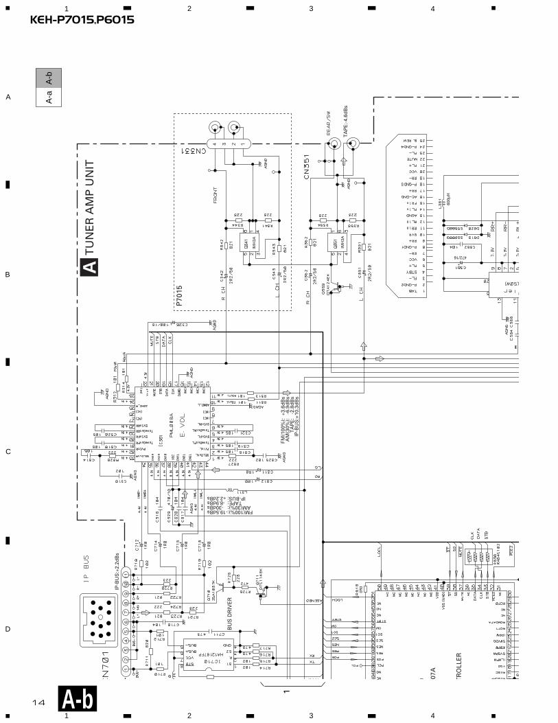
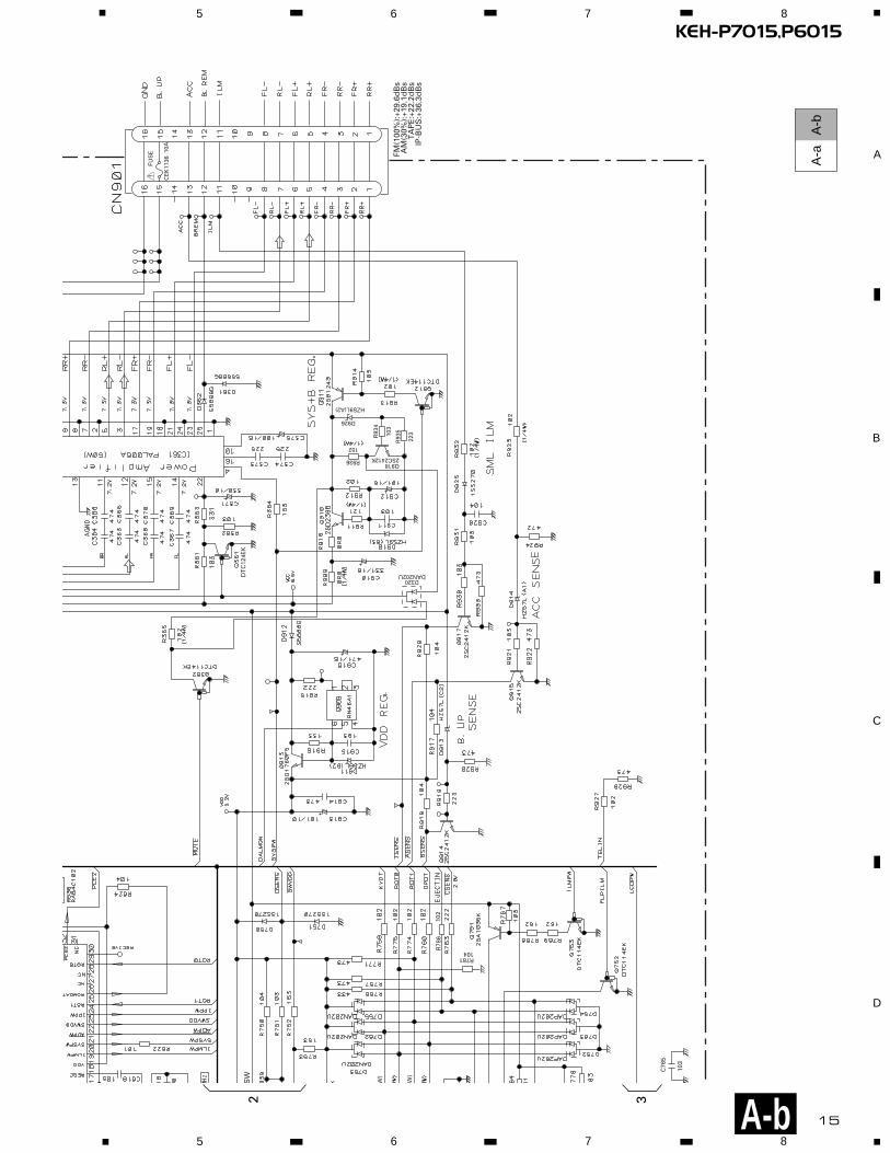
3. BLOCK DIAGRAM AND SCHEMATIC DIAGRAM
3.1 BLOCK DIAGRAM
Q710
Q711
IC 710HA12187FP
IP-BUS DRIVER
37
MUTE
X1
X2
ILB+
EJECT
CSENS
SW5V
DPDT
KYDT
ROT1
ROT0
BL+B
loadsw
MSIN PEE
69
100
stby55
65 RIMUTE
LCDPW6
EJE
CT
IN
4
DPDT96
KYDT95
ROT029
ROT125
23 20
SYSTEMCONTROLLER
IC 601(2/2)PE5207A
BUS—
B.U
BUS+
BUS+L
5
8
1
7
1
2
8
6
5 TX
RX
IPPW
SW
VD
D
77
CS
EN
S
ILM
PW
B.U
VDD
7
10
11
14
12
13
2
8
5
FILM—6
4
CN750
CN501
CN701
Q751
B.U
Q754
Q755
Q753
Q750
Q752
A TUNER AMP UNIT
FM/AM TUNER UNIT
BZ610ALARMBUZZER
16
X610
15
19
3
FLP
ILM
9
FILM+
72
mutemute
Q3
S750
PD
IO
Q410
LOCL VCCLOCH
B.U
stby
B.U
MUTE
LOAD
5
1
4
2
1
3
11
9
20
19
D DECK UNIT
IC251HA12229F
IC351PA2020A
EQ AMP
MECHANISMDRIVER
CN251CN252
CN254
CN255
CN253
6
16 MS
Lch
20
FWDL-ch
REVL-ch
37
36
39
18 19
17
3 1 5 6
8 7 10
CN2563 1 5 6
S1LOAD
S2MODE
EGN1REEL
SENSE
M
M
M2SUB
MOTOR
M1MAIN
MOTOR
52
1
E REEL SENSE PCB
11
6
5 5617 f/R
DIRO
68 66
DIROMS
9MCMUTE
stby
loadsw
15
13
15
1359
61POS
NES13
11 POS
NES
POS
ES
18
17
18
1756
57
16
15 SC1
CM
20 B.U
16 165814 SC2
SC1
CM
SC2
SC1
CM
SC2
VDD
CN402
6
21
18
22 19 12 15 16 8 13 32
4
ANT
1
28
27
2
IC 3EEPROM
FM/AM 1ST IF 10.7MHzT51 Q51 CF51 CF52 CF53
IC1MIXER, IF AMP, DET. LDET
COMP
CF202
VCC
DI/D
O
CE
2
CK
CE
1
SD
BW
SL
FMS
D
NL1
NL2
IC 2 FM MPX
AMANT
FMANT
ATT
ATT
AMRF
FMRF
IMG ADJ
RF ADJ
X90110.25MHz
ANT ADJ
LOCLLOCH
AMDETMPXREF 41kHz
AM 2ND IF450kHz
CR
EQ
ST
IND
L ch
1142523
5R ch
7
17
20
24
26
WC
NC
NC
FMLOCL
RFGND
11 DGND
10
VDD
9 NC
VCC
SYSPW21
SYSPW
9
KEH-P7015,P60155 6 7 8
5 6 7 8
D
C
B
A
C
11
1
adpw
bsens
asens
VDD B.U
B.U
B.U
8
92
93
83
10
22
SD
SL
PCE
PCK
pce@
PDO
ASENBO
10Fout L
11Rout L
B.U
SYSPW
IL+B
µGND
CSENS
SW5V
DPDT
KYDT
RDT1
RDT0
BL+B
ILB+
JECT
SENS
SW5V
PDT
YDT
ROT1
ROT0
BL+B
37
5
8
6
RL—
5 RL+
23 FL—
21 FL+
RL—
RL+
FL—
FL+
12B.REM
Lch
11ILM
13ACC
16GND
15BACK UP
BACK UP
GND
isens
AVREF
DALMON
38
74
TUN L41
BUS+L44
CD L42
99
97
32
98
71
86 85 24
FLIN14
RLIN12
22 4 25
SYSTEMCONTROLLER
RESET
POWER AMP
IC 301PML008A
IC 603S-80834ANY
IC 361PAL006A
IC 1902SBX8035-H
re
se
t
VDD
Q610
Q913
Q914
Q359 Q351
SYSPW
Q361
Q910 Q911
Q1905
Q917
TX
RX
IPP
W
ELECTRONIC VOLUME/SOURCE SELECTOR
B.REMSTBYMUTE
REMOTE CONTROLSENSOR
IC 1903PD6294A
LCD DRIVERKEY MATRIX
LCD
OPT IN1
9
8
7
10
3
5
6
4
11
7
10
11
14
12
13
2
7
8
4
8
5 5
ILM—6 6
4
10
11
14
12
13
2
4
3
6
5
10
8
7
9
2
3
DPDT
KYDT
X0
X1DIMMER
KEY DATA
LCD DATA
RE
MIN
VD
D
9
83
X1901
2
7
23 10
750 CN1951 CN1901CN1950
750
S1950
KEYBOARD UNITB PANEL UNIT
2
1
REAR/SWCN351
ACC
RL—
RL+
ILM
FL—
FL+
B.REM
2
CN901
ILM+
S1922
1
CN331
IC 601(1/2)PE5207A
5
1
Q909
6
Q915
20
MUTE
mute
Q362
Q912
Q341
st39
50
51LOCL
LOCH
VDD
7
5
8
6
12
11
13
16
15
P7015
P7015
Q918
VCC
VCC
DETACHSENSE SW

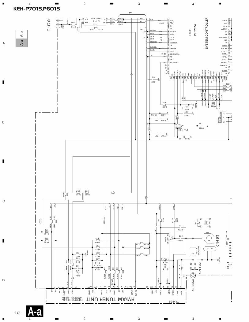
3.2 OVERALL CONNECTION DIAGRAM(GUIDE PAGE)Note: When ordering service parts, be sure to refer to “EXPLODED VIEWS AND PARTS LIST” or “ELECTRICAL PARTS
LIST”.
10
KEH-P7015,P60151 2 3 4
1 2 3 4
D
C
B
A
A-a A-b
A-aA-a A-b A-b
A-b A-b A-a A-a
Large sizeSCH diagram
Guide page
Detailed page
A
A-a
B
CN1901
DSP-201M
CN
251
102
821
102
473
R454
0R0
C62
4
223
C63
4
472
IMH3A
ANTENNA
EJECT SENSE SW
For resistors and capacitors in the circuit diagrams, their resistance values orcapacitance values are expressed in codes:
Ex. *Resistors Code Practical value 123 12k ohms 103 10k ohms
*Capacitors Code Practical value 103 0.01uF 101/10 100uF/10V
B PANEL UNIT
CK
EY
BO
AR
D U
NIT
FM/A
M T
UN
ER
UN
ITD
DE
CK
UN
IT
The > mark found on some component parts indicatesthe importance of the safety factor of the part.Therefore, when replacing, be sure to use parts ofidentical designation.
FM(1
00%
):-1
9.5d
Bs
AM
(30%
):
-30d
Bs
TA
PE
:-8.
9dB
s

11
KEH-P7015,P60155 6 7 8
5 6 7 8
D
C
B
AA-b
A
PE5207A
472/
16
600µH
>
CEK1136 10A
FUSE
SYSTEM CONTROLLER
BUS DRIVER
C765
103
R784
392 (1/10W)
R786 102
R787 472 (1/10W)
R788
R789 222 (1/10W)
222 (1/10W)
Q91
82S
C24
12K R934
103
R935
223
R93
6
152
D92
6
HZ
S9L
(A2)
D32
0D
AN
202U
DTC124EK
0R0
473
IMH3A
IMH3A
DETACH SENSE SW
C799473
(1/10W)
R78
110
4
A TUNER AMP UNIT
P7015
FM(100%): +3.6dBsAM(30%): -6.9dBs
TAPE: -2.8dBsIP-BUS:+10.3dBs
FM(100%):+29.6dBsAM(30%):+19.1dBs
TAPE:+22.2dBsIP-BUS:+36.3dBs
TAPE:-4.6dBs
FM(1
00%
):-1
9.5d
Bs
AM
(30%
):
-30d
Bs
TA
PE
: -8
.9d
Bs
IP-B
US
: +2.
2dB
s
IP-BUS:+2.2dBs
12
KEH-P7015,P60151 2 3 4
1 2 3 4
D
C
B
A
PE
5207
AD
SP
-201
M
SY
ST
EM
CO
NT
RO
LLE
R
1
1R
454
0R0
C624
223
C634
472
AN
TE
NN
A
FM/AM TUNER UNITFM(100%):-19.5dBsAM(30%): -30dBs
A-a
A-a
A-b
1

13
KEH-P7015,P60155 6 7 8
5 6 7 8
D
C
B
A
A-a
A-a
A-b
CN
1901
CN251
C76
5
103
R78
4
392
(1/1
0W)
R78
747
2 (1
/10W
)
R78
8
R78
922
2 (1
/10W
)
222
(1/1
0W)
102
821
102
473
IMH
3A
DE
TAC
H S
EN
SE
SW
EJE
CT
SE
NS
E S
W
C79
947
3
(1/1
0W)
For
resi
sto
rs a
nd
cap
acit
ors
in t
he
circ
uit
dia
gra
ms,
th
eir
resi
stan
ce v
alu
es o
rca
pac
itan
ce v
alu
es a
re e
xpre
ssed
in c
od
es:
Ex.
*R
esis
tors
C
od
e
P
ract
ical
val
ue
1
23
12k
oh
ms
1
03
10k
oh
ms
*C
apac
ito
rs
Co
de
P
ract
ical
val
ue
1
03
0.01
uF
1
01/1
0
100u
F/10
V
BP
AN
EL
UN
ITCKEYBOARD UNIT
DDECK UNIT
Th
e >
mar
k fo
un
d o
n s
om
e co
mp
on
ent
par
ts in
dic
ates
the
imp
ort
ance
of
the
safe
ty f
acto
r o
f th
e p
art.
Th
eref
ore
, wh
en r
epla
cin
g, b
e su
re t
o u
se p
arts
of
iden
tica
l des
ign
atio
n.
TAPE:-8.9dBs
B
2 3
14
1 2 3 4
1 2 3 4
D
C
B
A A-a
A-b
A-b
KEH-P7015,P6015
07A
472/16
600µ
H
TR
OLL
ER
BU
S D
RIV
ER
0R0
IMH
3A
IMH
3A
AT
UN
ER
AM
P U
NIT
P70
15
FM(1
00%
): +
3.6d
Bs
AM
(30%
):
-6.9
dB
sT
AP
E:
-2.
8dB
sIP
-BU
S:+
10.3
dB
s
TA
PE
:-4.
6dB
s
FM(100%):-19.5dBsAM(30%): -30dBs
TAPE: -8.9dBsIP-BUS: +2.2dBs
IP-B
US
:+2.
2dB
s
1
15
5 6 7 8
5 6 7 8
D
C
B
A
A-b
A-a
A-b
KEH-P7015,P6015
> CE
K11
3610
A
FUS
E
C76
5
103
R78
610
2
W)
W)
Q9182SC2412K
R93
4
103
R93
5
223
R936
152
D926
HZS9L(A2)
D320DAN202UD
TC
124E
KS
W
R781104
FM(1
00%
):+2
9.6d
Bs
AM
(30%
):+1
9.1d
Bs
TA
PE
:+22
.2d
Bs
IP-B
US
:+36
.3d
Bs
2 3
16
KEH-P7015,P60151 2 3 4
1 2 3 4
D
C
B
A
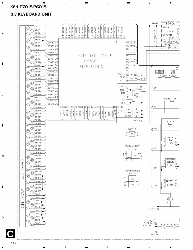
3.3 KEYBOARD UNIT
REMOTE CONTROLSENSOR
PURE GREEN
PURE GREEN
P7015
P6015
P7015:151 161P6015:201 201
TA
BAND
DOWN
CA
W16
28
C

17
KEH-P7015,P60155 6 7 8
5 6 7 8
D
C
B
A
ONTROLSOR
P7015:CL170UBXP6015:CL170PGCD
P7015
161201
472
R19
27
C KEYBOARD UNIT
BC
N19
51P
AN
EL
UN
IT
AUDIOSFEQ
DISPFUNC
EQSOURCEPTY
A CH3 CH2 CH1
CH4CH5CH6ND
WN UP RIGHT LEFT
C

18
KEH-P7015,P60151 2 3 4
1 2 3 4
D
C
B
A
D
3.4 CASSETTE MECHANISM MODULE
CN551
D
A
DECK UNIT
MU
TE
HA12229F
11121314151617181920
40393837363534333231
30 29 28 27 26 25 24 23 22 21
1 2 3 4 5 6 7 8 9 10
C25
3
390P
C25
1
C256
R01
C405 R033
R404 270K
R01C404
910R403
3R3K
C255
R01
C272R1
C40
1
3900
P
R28
50R
0
HD1HEAD ASSYEXA1592
TEST TAPENCT-150(400Hz, 200nWb/m)
RL
RR
FR
FL
C30
2
R1
C30
1
R1
R30
4R
302
16K
16K
R30
1
16K
R30
3
16K
-8.24dBs±4dB
Fwd-R
Fwd-L
Rev-R
Rev-L
NF1(R)
Vref1
RIN(L)
NC
RIN(R)
GND
FIN(R)
Vref2
FIN(L)
NFI(L)
M-O
UT
(L)
EQ
OU
T(L
)
Vre
f4
TA
I(L)
BIA
S
NC
NC
MS
GV
(S)
MUTE
120/70
ser/REP
f/R
MSDET
MSI
MAOUT
MSGV(R)
MO
UT
(R)
EQ
OU
T(R
)
Vre
f3
TA
I(R
)
RIP
PB
OU
T(R
)
NC
NC
NC
CN252
CN251
EQ AMP
IC251
390P
C25
2
390P
C25
4
390P
PB
OU
T(L
)
NC
VCC
MSOUT
NC
C40
3
R02
2
R40
2
R33
C40
2
15K
R40
118K
R27
1C
271
1/50

REEL SENSEPCB
SWITCHES:REEL SENSE PCB S1:LOAD SWITCH..........EJECT-PLAY S2:MODE SWITCH............ON-OFFThe underlined indicates the switch position.
3
R35
11K
R35
21K
R35
31K
R35
41K
R373 0R0
R35
527
0K
C35
239
00P
R36
230
0
C35
1R
22
C35
3R
01
C35
4R
01
R374 0R0
C356 R01
C355 R1D35
21S
S35
5
M1 MOTOR UNIT(MAIN MOTOR)EXA1491
S1 LOADESG1007
S2ESG1007
MODE
REEL SENSE
EGN1EGN1004
M2MOTOR UNIT(SUB MOTOR)EXA1580
RS3
RS2
RS1
SC2
SC1
TAB
MC
CE
VCC2
NC
VCC
MCS
RRS
FRS
RSB
C
TAB
MS2
NC
NC
MM
SM1
RSB
GND
RS
mtl
MCS
load
CN255
CN253CN256
CN254
MECHANISMDRIVER
IC35
1
PA
2020
A
R02
2
Decimal points for resistorand capacitor fixed valuesare expressed as :2.2 2R20.022 R022
← ←
Symbol indicates a resistor.No differentiation is made between chip resistors anddiscrete resistors.
NOTE :
Symbol indicates a capacitor.No differentiation is made between chip capacitors anddiscrete capacitors.
D 19
KEH-P7015,P60155 6 7 8
5 6 7 8
D
C
B
A
E
E

20
KEH-P7015,P60151 2 3 4
1 2 3 4
D
C
B
A
CORD ASSY
CORD
DETACHSENSE SW
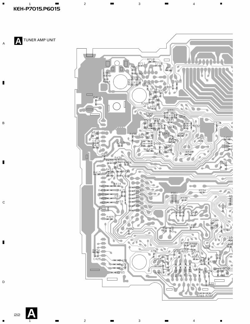
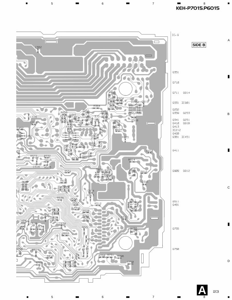
4. PCB CONNECTION DIAGRAM
4.1 TUNER AMP UNIT
NOTE FOR PCB DIAGRAMS
1. The parts mounted on this PCB
include all necessary parts for
several destination.
For further information for
respective destinations, be sure
to check with the schematic dia-
gram.
2. Viewpoint of PCB diagrams
A
CapacitorConnector
P.C.Board Chip Part
SIDE A
SIDE B
TUNER AMP UNITA

21
KEH-P7015,P60155 6 7 8
5 6 7 8
D
C
B
A
AFRONT
CN251
ANTENNAJACK
REAR OUTPUT
IP-BUS INPUT
FM/A
M T
UN
ER
UN
IT
D
CN1950B
CORD ASSY SIDE A
22
KEH-P7015,P60151 2 3 4
1 2 3 4
D
C
B
A
321
456
123
654
123
654
654
123
A
TUNER AMP UNITA
23
KEH-P7015,P60155 6 7 8
5 6 7 8
D
C
B
A
A
321
456
321
456
SIDE B
24
KEH-P7015,P60151 2 3 4
1 2 3 4
D
C
B
A
B
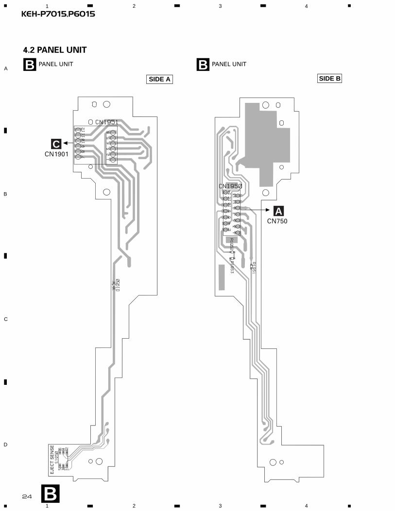
PANEL UNITB4.2 PANEL UNIT
CN1901C
EJE
CT
SE
NS
E
CN750A
SIDE BSIDE A
PANEL UNITB

25
KEH-P7015,P60151 2 3 4
1 2 3 4
D
C
B
A
CN1951B
C
SIDE B
4.3 KEYBOARD UNIT
SIDE AKEYBOARD UNITC
EQ
SO
UR
CE
DIS
P1
23
45
6P
RO
GC
LKB
AN
D
FUN
C
AU
DIO
SFE
Q
246
642
135
531
531
642
135
246
KEYBOARD UNITC

IC,Q
IC251
Q351
Q352
ADJ
VR302
VR301
IC351 CN252
CN254CN253
CN255
M1M2HEAD ASSY
CN256
2122
CN251
C271
26
KEH-P7015,P60151 2 3 4
1 2 3 4
D
C
B
A
DECK UNIT CN551
4.4 CASSETTE MECHANISM MODULE
SIDE A
SIDE B
D
E
A
DECK UNIT
D
D

123456
S1LOAD
S2MODE
CN256
EGN1REEL SENSE
27
KEH-P7015,P60151 2 3 4
1 2 3 4
D
C
B
AREEL SENSE PCB
CN253
E
E
D
28
KEH-P7015,P6015
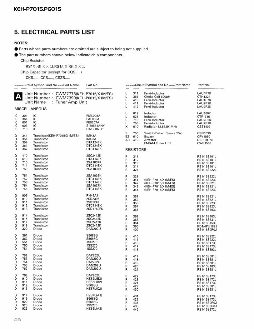
5. ELECTRICAL PARTS LIST
NOTES:
- Parts whose parts numbers are omitted are subject to being not supplied.
- The part numbers shown below indicate chip components.
Chip Resistor
RS1/_S___J,RS1/__S___J
Chip Capacitor (except for CQS.....)
CKS....., CCS....., CSZS.....
=====Circuit Symbol and No.===Part Name Part No.--- ------ ------------------------------------------ -------------------------
Unit Number : CWM7773(KEH-P7015/X1M/ES)Unit Number : CWM7390(KEH-P6015/X1M/ES)Unit Name : Tuner Amp Unit
MISCELLANEOUS
IC 301 IC PML008AIC 361 IC PAL006AIC 601 IC PE5207AIC 603 IC S-80834ANYIC 710 IC HA12187FP
Q 341 Transistor(KEH-P7015/X1M/ES) IMH3AQ 351 Transistor IMH3AQ 359 Transistor DTA124EKQ 361 Transistor DTC124EKQ 362 Transistor DTC114EK
Q 410 Transistor 2SC2412KQ 610 Transistor DTA114EKQ 710 Transistor 2SA1037KQ 711 Transistor DTC114EKQ 750 Transistor 2SA1037K
Q 751 Transistor 2SA1036KQ 752 Transistor DTC114EKQ 753 Transistor DTC114EKQ 754 Transistor 2SA1037KQ 755 Transistor DTC114EK
Q 909 Transistor RN46A1Q 910 Transistor 2SD2396Q 911 Transistor 2SB1243Q 912 Transistor DTC114EKQ 913 Transistor 2SD1760F5
Q 914 Transistor 2SC2412KQ 915 Transistor 2SC2412KQ 917 Transistor 2SC2412KQ 918 Transistor 2SC2412KD 320 Diode DAN202U
D 361 Diode S5688GD 362 Diode S5688GD 551 Diode 1SS270D 750 Diode 1SS270D 751 Diode 1SS270
D 752 Diode DAP202UD 753 Diode DAN202UD 754 Diode DAP202UD 755 Diode DAN202UD 762 Diode DAN202U
D 763 Diode DAP202UD 910 Diode HZS9L(B3)D 911 Diode HZS6L(B2)D 912 Diode S5688GD 913 Diode HZS7L(C2)
D 914 Diode HZS7L(A1)D 919 Diode S5688GD 920 Diode S5688GD 925 Diode 1SS270D 926 Diode HZS9L(A2)
L 311 Ferri-Inductor LAU4R7KL 361 Choke Coil 600µH CTH1221L 410 Ferri-Inductor LAU4R7KL 411 Ferri-Inductor LAU2R2KL 412 Ferri-Inductor LAU2R2K
L 612 Inductor LAU100KL 621 Inductor CTF1346L 710 Ferri-Inductor LAU2R2KL 750 Ferri-Inductor LAU2R2KX 610 Radiator 12.58291MHz CSS1402
S 750 Switch(Detach Sense SW) CSN1039BZ 610 Buzzer CPV1050AR 410 Arrester DSP-201M
FM/AM Tuner Unit CWE1563
RESISTORS
R 311 RS1/16S101JR 312 RS1/16S101JR 313 RS1/16S101JR 314 RS1/16S101JR 327 RS1/16S222J
R 328 RS1/16S222JR 341 (KEH-P7015/X1M/ES) RS1/16S223JR 342 (KEH-P7015/X1M/ES) RS1/16S821JR 343 (KEH-P7015/X1M/ES) RS1/16S821JR 344 (KEH-P7015/X1M/ES) RS1/16S223J
R 351 RS1/16S821JR 352 RS1/16S821JR 353 RS1/16S223JR 354 RS1/16S223JR 361 RS1/16S103J
R 362 RS1/16S103JR 363 RS1/16S331JR 364 RS1/16S153JR 365 RD1/4PU182JR 409 RS1/16S0R0J
R 410 RS1/16S222JR 411 RS1/16S222JR 413 RS1/16S473JR 414 RS1/16S473JR 415 RS1/16S393J
R 417 RS1/16S681JR 418 RS1/16S681JR 419 RS1/16S681JR 420 RS1/16S103JR 421 RS1/16S681J
R 422 RS1/16S473JR 423 RS1/16S472JR 424 RS1/16S473JR 429 RS1/16S681JR 430 RS1/16S681J
R 431 RS1/16S473JR 432 RS1/16S473JR 437 RS1/16S0R0JR 438 RS1/16S0R0JR 445 RS1/16S272J
=====Circuit Symbol and No.===Part Name Part No.--- ------ ------------------------------------------ -------------------------
A

KEH-P7015,P6015
R 446 RS1/16S272JR 447 RS1/16S162JR 448 RS1/16S162JR 454 RS1/16S0R0JR 551 RS1/16S203J
R 552 RS1/16S473JR 553 RS1/16S473JR 554 RS1/16S473JR 555 RS1/16S104JR 556 RS1/16S473J
R 557 RS1/16S473JR 558 RS1/16S102JR 561 RAB4C102JR 562 RAB4C102JR 563 RAB4C102J
R 569 RS1/16S681JR 572 RS1/16S102JR 573 RS1/16S102JR 611 RS1/16S473JR 613 RS1/16S102J
R 614 RS1/16S821JR 615 RS1/16S102JR 616 RS1/16S0R0JR 620 RS1/16S473JR 621 RS1/16S0R0J
R 622 RS1/16S101JR 624 RS1/16S104JR 625 RS1/16S0R0JR 626 RS1/16S473JR 627 RS1/16S473J
R 628 RS1/16S473JR 630 RAB4C102JR 710 RS1/16S101JR 711 RS1/16S620JR 712 RS1/16S101J
R 713 RS1/16S103JR 714 RS1/16S102JR 715 RS1/16S102JR 716 RS1/16S473JR 717 RS1/16S473J
R 718 RS1/16S102JR 719 RS1/16S102JR 720 RS1/16S223JR 721 RS1/16S223JR 722 RS1/16S821J
R 723 RS1/16S821JR 724 RS1/16S222JR 725 RS1/16S223JR 726 RS1/16S472JR 750 RS1/16S104J
R 751 RS1/16S103JR 752 RS1/16S153JR 753 RS1/16S153JR 754 RS1/16S222JR 756 RS1/16S433J
R 757 RS1/16S473JR 758 RS1/16S102JR 759 RD1/4PU222JR 760 RS1/16S102JR 763 RS1/16S222J
R 764 RS1/16S131JR 765 RS1PMF390JR 766 RS1/10S270JR 767 RS1/16S103JR 768 RS1/16S152J
R 769 RS1/16S152JR 771 RS1/16S473JR 773 RD1/4PU222JR 774 RS1/16S102JR 775 RS1/16S102J
R 776 RS1/16S220JR 777 RS1/16S0R0JR 778 RS1/16S103JR 779 RS1/16S472JR 781 RS1/16S104J
R 782 RS1/16S131JR 783 RS1/16S131JR 784 RS1/10S392JR 786 RS1/16S102JR 787 RS1/10S472J
R 788 RS1/10S222JR 789 RS1/10S222JR 909 RD1/4PU0R0JR 910 RS1/16S0R0JR 911 RD1/4PU121J
R 912 RS1/16S102JR 913 RD1/4PU102JR 914 RS1/16S103JR 915 RS1/16S222JR 916 RS1/16S133J
R 917 RS1/16S104JR 918 RS1/16S104JR 919 RS1/16S223JR 920 RS1/16S473JR 921 RS1/16S103J
R 922 RS1/16S473JR 923 RD1/4PU102JR 924 RS1/16S472JR 927 RS1/16S102JR 928 RS1/16S473J
R 929 RS1/16S104JR 930 RS1/16S103JR 931 RS1/16S103JR 932 RD1/4PU102JR 933 RS1/16S473J
R 934 RS1/16S103JR 935 RS1/16S223JR 936 RD1/4PU152J
CAPACITORS
C 310 CKSRYB102K50C 311 CEJA1R0M50C 312 CEJA1R0M50C 314 CKSRYB105K6R3C 315 CKSRYB105K6R3
C 316 CKSRYB104K16C 317 CKSRYB104K16C 318 CKSRYB105K6R3C 319 CKSRYB105K6R3C 320 CKSRYB105K6R3
C 321 CKSRYB105K6R3C 325 CKSRYB102K50C 326 CEJA100M16C 328 CKSRYB104K16C 329 CEJA470M10
C 342 (KEH-P7015/X1M/ES) CEJA2R2M50C 343 (KEH-P7015/X1M/ES) CEJA2R2M50C 351 CEJA2R2M50C 352 CEJA2R2M50C 361 4700µF/16V CCH1367
C 362 CKSQYB104K16C 363 CKSQYB474K16C 364 CKSQYB474K16C 365 CKSQYB474K16C 366 CKSQYB474K16
C 367 CKSQYB474K16C 368 CKSQYB474K16C 369 CKSQYB474K16C 370 CKSQYB474K16C 371 CEJA330M10
=====Circuit Symbol and No.===Part Name Part No.--- ------ ------------------------------------------ -------------------------
=====Circuit Symbol and No.===Part Name Part No.--- ------ ------------------------------------------ -------------------------
29

30
KEH-P7015,P6015
C 373 CKSQYB225K10C 374 CKSQYB225K10C 375 CEJA100M16C 410 CKSQYB103K50C 412 CKSRYB223K25
C 413 CKSRYB102K50C 414 CEJA220M10C 415 CKSRYB223K25C 418 CEAL101M10C 419 CKSRYB473K16
C 424 CKSRYB183K25C 425 CKSRYB183K25C 431 CKSRYB102K50C 551 CEJA220M10C 552 CEJA220M16
C 615 CEAL2R2M50C 616 CCSRCH200J50C 617 CCSRCH200J50C 618 CKSRYB105K6R3C 619 CEAL4R7M35
C 620 CKSRYB103K50C 621 CCSRCH101J50C 624 CKSRYB223K25C 629 CCSRCH101J50C 630 CKSRYB103K50
C 631 CCSRCH101J50C 632 CCSRCH101J50C 633 CKSRYB103K50C 634 CKSRYB472K50C 710 CKSRYB104K16
C 711 CKSRYB473K16C 712 CEJA1R0M50C 713 CEJA1R0M50C 714 CEJA1R0M50C 715 CEJA1R0M50
C 750 CKSRYB103K25C 751 CKSQYB104K16C 765 CKSQYB103K50C 799 CKSQYB473K16C 910 330µF/16V CCH1326
C 911 CKSRYB103K25C 912 CEJA101M16C 913 CEJA101M10C 914 CKSRYB473K16C 915 CKSRYB103K25
C 916 470µF/16V CCH1331C 920 CKSRYB104K16
Unit Number : CWM7772(KEH-P7015/X1M/ES)Unit Name : Keyboard Unit
MISCELLANEOUS
IC 1902 IC SBX8035-HIC 1903 IC PD6294AQ 1905 Transistor DTC114EUD 1901 Chip Diode MA151WKD 1902 Chip Diode MA151WA
D 1903 LED CL170UBXD 1917 LED NSSW440-9159D 1918 LED NSSW440-9159X 1901 Radiator 5.00MHz CSS1423S 1901 Push Switch CSG1112
S 1902 Push Switch CSG1112S 1903 Push Switch CSG1112S 1904 Push Switch CSG1112S 1905 Switch CSG1107S 1906 Push Switch CSG1112
S 1908 Switch CSG1107S 1909 Switch CSG1107S 1910 Switch CSG1107S 1911 Switch CSG1107S 1912 Switch CSG1107
S 1913 Switch CSG1107S 1914 Switch CSG1107S 1915 Switch CSG1107S 1916 Push Switch CSG1112S 1917 Push Switch CSG1112
S 1918 Push Switch CSG1112S 1919 Push Switch CSG1112S 1920 Push Switch CSG1111S 1922 Switch CSD1061
LCD CAW1628
RESISTORS
R 1901 RS1/10S222JR 1902 RS1/10S222JR 1903 RS1/16S470JR 1904 RS1/16S470JR 1905 RS1/16S121J
R 1906 RS1/16S2R2JR 1909 RS1/16S151JR 1910 RS1/16S121JR 1911 RS1/16S121JR 1912 RS1/16S121J
R 1913 RS1/16S121JR 1914 RS1/16S121JR 1915 RS1/16S121JR 1916 RS1/16S121JR 1917 RS1/16S131J
R 1918 RS1/16S151JR 1919 RS1/16S131JR 1920 RS1/16S131JR 1927 RS1/16S472JR 1929 RS1/16S0R0J
R 1930 RS1/16S101JR 1931 RS1/16S101JR 1933 RS1/16S161JR 1935 RS1/16S393JR 1936 RS1/16S131J
R 1938 RS1/16S151JR 1939 RS1/16S131JR 1941 RS1/16S131JR 1942 RS1/16S131JR 1943 RS1/16S131J
R 1945 RS1/16S121JR 1946 RS1/16S0R0JR 1949 RS1/16S151J
CAPACITORS
C 1902 CKSRYB104K16C 1903 CSZS100M6R3C 1905 CKSRYB104K16C 1906 CKSRYB104K16C 1907 CKSRYB104K16
C 1923 CKSQYB104K16C 1924 CKSRYB104K16C 1930 CKSQYB104K16
=====Circuit Symbol and No.===Part Name Part No.--- ------ ------------------------------------------ -------------------------
=====Circuit Symbol and No.===Part Name Part No.--- ------ ------------------------------------------ -------------------------
C

Unit Number : CWM7793(KEH-P6015/X1M/ES)Unit Name : Keyboard Unit
MISCELLANEOUS
IC 1903 IC PD6294AQ 1905 Transistor DTC114EUD 1901 Chip Diode MA151WKD 1902 Chip Diode MA151WAD 1903 LED CL170PGCD
D 1917 LED NSSW440-9159D 1918 LED NSSW440-9159X 1901 Radiator 5.00MHz CSS1423S 1901 Push Switch CSG1112S 1902 Push Switch CSG1112
S 1903 Push Switch CSG1112S 1904 Push Switch CSG1112S 1905 Switch CSG1107S 1906 Push Switch CSG1112S 1908 Switch CSG1107
S 1909 Switch CSG1107S 1910 Switch CSG1107S 1911 Switch CSG1107S 1912 Switch CSG1107S 1913 Switch CSG1107
S 1914 Switch CSG1107S 1915 Switch CSG1107S 1916 Push Switch CSG1112S 1917 Push Switch CSG1112S 1918 Push Switch CSG1112
S 1919 Push Switch CSG1112S 1920 Push Switch CSG1111S 1922 Switch CSD1061
LCD CAW1628
RESISTORS
R 1900 RS1/16S473JR 1901 RS1/10S222JR 1902 RS1/10S222JR 1903 RS1/16S470JR 1904 RS1/16S470J
R 1909 RS1/16S201JR 1910 RS1/16S121JR 1911 RS1/16S121JR 1912 RS1/16S121JR 1913 RS1/16S121J
R 1914 RS1/16S121JR 1915 RS1/16S121JR 1916 RS1/16S121JR 1917 RS1/16S131JR 1918 RS1/16S151J
R 1919 RS1/16S131JR 1920 RS1/16S131JR 1927 RS1/16S472JR 1929 RS1/16S0R0JR 1930 RS1/16S101J
R 1931 RS1/16S101JR 1933 RS1/16S201JR 1935 RS1/16S393JR 1936 RS1/16S131JR 1938 RS1/16S151J
R 1939 RS1/16S131JR 1941 RS1/16S131JR 1942 RS1/16S131JR 1943 RS1/16S131JR 1945 RS1/16S121J
R 1946 RS1/16S0R0JR 1949 RS1/16S151J
CAPACITORS
C 1902 CKSRYB104K16C 1905 CKSRYB104K16C 1906 CKSRYB104K16C 1907 CKSRYB104K16C 1923 CKSQYB104K16
C 1930 CKSQYB104K16
Unit Number : CWM7627Unit Name : Panel Unit
MISCELLANEOUS
S 1950 Push Switch(EJECT SENSE) CSG1112
RESISTORS
R 1951 RS1/16S101JR 1952 RS1/16S101JR 1953 RS1/16S101J
Unit Number :Unit Name : Deck Unit
MISCELLANEOUS
IC 251 IC HA12229FIC 351 IC PA2020AD 352 Diode 1SS355
RESISTORS
R 271 RS1/16S183JR 285 RS1/16S0R0JR 301 RS1/16S163JR 302 RS1/16S163JR 303 RS1/16S163J
R 304 RS1/16S163JR 351 RS1/16S102JR 352 RS1/16S102JR 353 RS1/16S102JR 354 RS1/16S102J
R 355 RS1/16S274JR 362 RS1/8S301JR 373 RS1/16S0R0JR 374 RS1/8S0R0JR 401 RS1/16S153J
R 402 RS1/16S332JR 403 RS1/16S911JR 404 RS1/16S274J
CAPACITORS
C 251 CKSRYB391K50C 252 CKSRYB391K50C 253 CKSRYB391K50C 254 CKSRYB391K50C 255 CKSRYB103K50
C 256 CKSRYB103K50C 271 1µF/50V ECH0002C 272 CKSRYB104K16C 301 CKSRYB104K16C 302 CKSRYB104K16
C 351 CKSQYB224K25C 352 CKSRYB392K50C 353 CKSRYB103K50C 354 CKSRYB103K50C 355 CKSQYB104K50
KEH-P7015,P6015
=====Circuit Symbol and No.===Part Name Part No.--- ------ ------------------------------------------ -------------------------
31
D
B
=====Circuit Symbol and No.===Part Name Part No.--- ------ ------------------------------------------ -------------------------
C

356 CKSRYB103K50C 401 CKSRYB392K50C 402 CKSRYB334K10C 403 CKSRYB223K25C 404 CKSRYB103K50
C 405 CKSRYB333K16
Unit Number :Unit Name : Reel Sense PCB
S 1 Switch(LOAD) ESG1007S 2 Switch(MODE) ESG1007EGN 1 Photo-reflector EGN1004
Miscellaneous Parts List
M 1 Motor Unit(MAIN) EXA1491M 2 Motor Unit(SUB) EXA1580HD 1 Head Assy EXA1592
32
KEH-P7015,P6015
6. ADJUSTMENT
There is no information to be shown in this chapter.
E
=====Circuit Symbol and No.===Part Name Part No.--- ------ ------------------------------------------ -------------------------

7. GENERAL INFORMATION
7.1 DIAGNOSIS
7.1.1 DISASSEMBLY
- Removing the Tuner Amp Unit (Fig.2)
Remove the two screws.
Straight the tabs at three locations indicated.
Remove the screw.
Remove the three screws and then remove
the Tuner Amp Unit.
*) Tuner Amp Unit is different partially from this
photo.
- Removing the Case (not shown)
1. Remove the Case.
- Removing the Cassette Mechanism Module (Fig.1)
Remove the four screws and then remove the
Cassette Mechanism Module.
- Removing the Panel Assy (Fig.1)
Remove the two screws and then remove the Panel
Assy.
Fig.1
Fig.2Tuner Amp Unit
Cassette Mechanism Module
Panel Assy
33
KEH-P7015,P6015
34
KEH-P7015,P6015
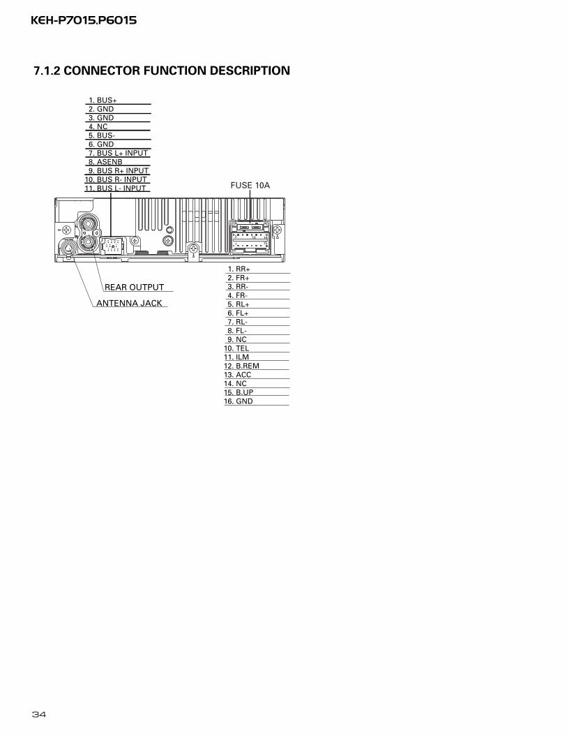
7.1.2 CONNECTOR FUNCTION DESCRIPTION
111098
765
4321
1. RR+ 2. FR+ 3. RR- 4. FR- 5. RL+ 6. FL+ 7. RL- 8. FL- 9. NC10. TEL11. ILM12. B.REM13. ACC14. NC15. B.UP16. GND
REAR OUTPUT
ANTENNA JACK
FUSE 10A
1
2 10 1615
1. BUS+ 2. GND 3. GND 4. NC 5. BUS- 6. GND 7. BUS L+ INPUT 8. ASENB 9. BUS R+ INPUT10. BUS R- INPUT11. BUS L- INPUT
35
KEH-P7015,P6015
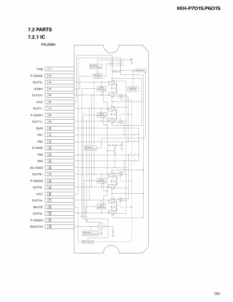
7.2 PARTS
7.2.1 IC
1
TAB
2
P-GND2
3
OUT2-
4
STBY
5
OUT2+
6
VCC
7
OUT1-
8
P-GND1
9
OUT1+
10SVR
11IN1
12IN2
13S-GND
14IN4
15IN3
16AC-GND
17OUT3+
18P-GND3
19OUT3-
20VCC
21OUT4+
22MUTE
23OUT4-
24P-GND4
SWITCH
25
+-
+ -
OffsetDetection
+-
+ -
OffsetDetection
+-
+ -
OffsetDetection
+-
+ -
OffsetDetection
Protector;Over current limit
sw_v
cc
stby
Protector;Short circuit
Mute circuit
am
p_v
cc
Stand-byCircuit
Protector;Over voltage
sw_v
cc
Protector;Thermal
Referenceamp_vcc
PAL006A
36
KEH-P7015,P6015
DG
ND
CLK Vre
f
NC
MU
TE
ST
B
DA
TA
IN4
-_R
IN4+
_R
IN3_
R
IN1_
R
IN2_
R
Vcc
IN1_
L
IN2_
L
IN3_
L
IN4+
_L
IN4
-_L
12
11
10
9
8
7
6
5
4
3
2
1
2019181716151413
30
29
28
27
26
25
24
23
2221
40 39 38 37 36 35 34
33
32
31
44 43 42 41
Tone_out_RL
SV_in_RL
SV_in_FL
Tone_out_FL
Front_out_L
Rear_out_LN
C
NC
NC
NC
PV_in_RPV_in_L
Sel_out_R
AGND_L
NC
NC
NC
NC
Tone_out_FR
AGND_R
SV_in_RR
SV_in_FR
Tone_out_RR
Rear_out_R
Front_out_R
Sel_out_L Isolatorcircuit
Digital blockZero cross
Secondaryvolume
MUTESecondary
volume
Treble2
Bass2
Anti radiationfilter
Anti radiationfilter
Primaryvolume
Anti Aliasfilter
LoudnessvolumeBassMiddleTreble
from Rch to Rch
LPF(L+R)
Rch block (same as Lch)
detect circuit
SourceGain
adjuster
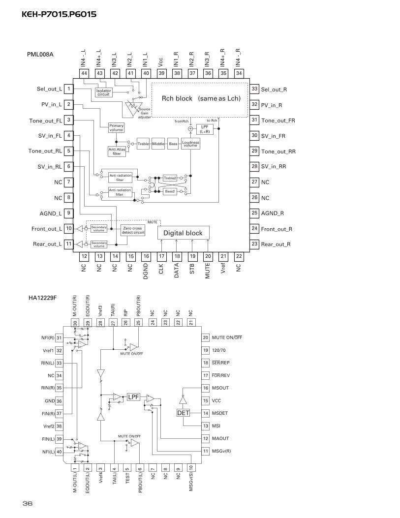
PML008A
HA12229F
30
TAI(
L)
29
TE
ST
28
PB
OU
T(L
)
27
NC
26
NC
25
NC
31NFI(R)
32Vref1
33RIN(L)
34NC
35RIN(R)
11
12
13
14
15
16
17
18
20
19
MUTE ON/off
MSOUT
120/70
ser/REP
for/REV
VCC
MSDET
MSI
MAOUT
MSGv(R)
36
37
4 5
GND
FIN(R)
M-O
UT
(R)
Vre
f3
38
6
Vref2
EQ
OU
T(R
)
39
7
FIN(L)
TAI(
R)
40
8
NFI(L)
RIP
1 9
M-O
UT
(L)
PB
OU
T(R
)
2 10
EQ
OU
T(L
)
NC
3V
ref4
24 23 22 21M
SG
v(S
)
NC
NC
NC
LPF
DET
MUTE ON/off
MUTE ON/off
37
KEH-P7015,P6015
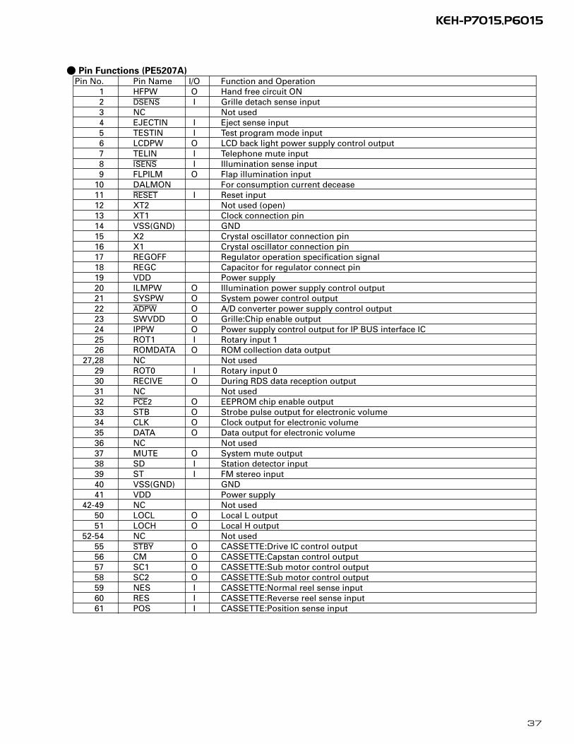
- Pin Functions (PE5207A)Pin No. Pin Name I/O Function and Operation
1 HFPW O Hand free circuit ON2 dsens I Grille detach sense input3 NC Not used4 EJECTIN I Eject sense input5 TESTIN I Test program mode input6 LCDPW O LCD back light power supply control output7 TELIN I Telephone mute input8 isens I Illumination sense input9 FLPILM O Flap illumination input
10 DALMON For consumption current decease11 reset I Reset input12 XT2 Not used (open)13 XT1 Clock connection pin14 VSS(GND) GND15 X2 Crystal oscillator connection pin16 X1 Crystal oscillator connection pin17 REGOFF Regulator operation specification signal18 REGC Capacitor for regulator connect pin19 VDD Power supply20 ILMPW O Illumination power supply control output21 SYSPW O System power control output22 adpw O A/D converter power supply control output23 SWVDD O Grille:Chip enable output24 IPPW O Power supply control output for IP BUS interface IC25 ROT1 I Rotary input 126 ROMDATA O ROM collection data output
27,28 NC Not used29 ROT0 I Rotary input 030 RECIVE O During RDS data reception output31 NC Not used32 pce2 O EEPROM chip enable output33 STB O Strobe pulse output for electronic volume34 CLK O Clock output for electronic volume35 DATA O Data output for electronic volume36 NC Not used37 MUTE O System mute output38 SD I Station detector input39 ST I FM stereo input40 VSS(GND) GND41 VDD Power supply
42-49 NC Not used50 LOCL O Local L output51 LOCH O Local H output
52-54 NC Not used55 stby O CASSETTE:Drive IC control output56 CM O CASSETTE:Capstan control output57 SC1 O CASSETTE:Sub motor control output58 SC2 O CASSETTE:Sub motor control output59 NES I CASSETTE:Normal reel sense input60 RES I CASSETTE:Reverse reel sense input61 POS I CASSETTE:Position sense input
38
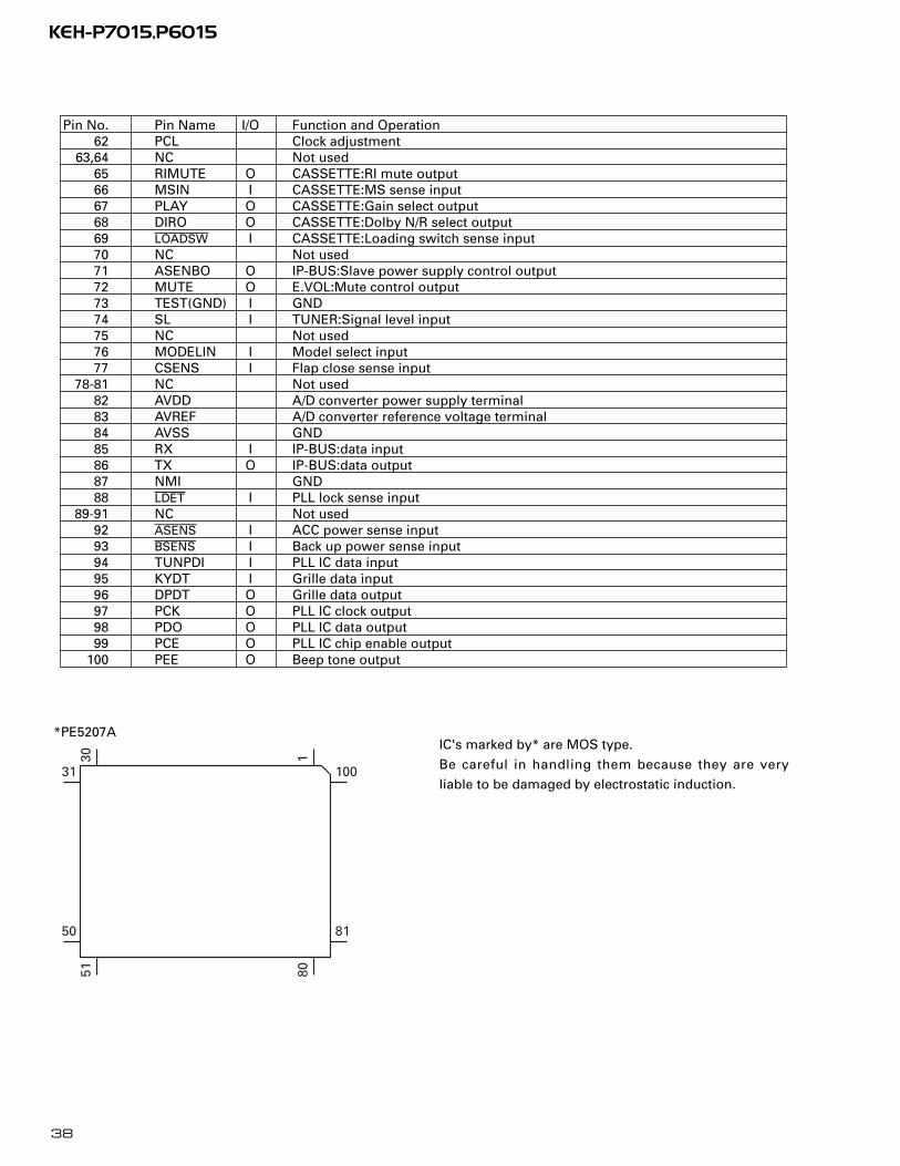
KEH-P7015,P6015
IC's marked by* are MOS type.
Be careful in handling them because they are very
liable to be damaged by electrostatic induction.
*PE5207A
Pin No. Pin Name I/O Function and Operation62 PCL Clock adjustment
63,64 NC Not used65 RIMUTE O CASSETTE:RI mute output66 MSIN I CASSETTE:MS sense input67 PLAY O CASSETTE:Gain select output68 DIRO O CASSETTE:Dolby N/R select output69 loadsw I CASSETTE:Loading switch sense input70 NC Not used71 ASENBO O IP-BUS:Slave power supply control output72 MUTE O E.VOL:Mute control output73 TEST(GND) I GND74 SL I TUNER:Signal level input75 NC Not used76 MODELIN I Model select input77 CSENS I Flap close sense input
78-81 NC Not used82 AVDD A/D converter power supply terminal83 AVREF A/D converter reference voltage terminal84 AVSS GND85 RX I IP-BUS:data input86 TX O IP-BUS:data output87 NMI GND88 ldet I PLL lock sense input
89-91 NC Not used92 asens I ACC power sense input93 bsens I Back up power sense input94 TUNPDI I PLL IC data input95 KYDT I Grille data input96 DPDT O Grille data output97 PCK O PLL IC clock output98 PDO O PLL IC data output99 PCE O PLL IC chip enable output
100 PEE O Beep tone output
30
31
50
51 80
81
100
1

39
KEH-P7015,P6015
- Pin Functions (PD6294A)Pin No. Pin Name I/O Function and Operation
1 VSS GND2 X1 Crystal oscillator connection pin3 X0 Crystal oscillator connection pin4 NC Not used
5,6 MOD1,0 I Connect to GND7 DIMMER O Dimmer select output8 KYDT O Key data output9 DPDT I Display data input
10 REMIN I Remote control pulse input11 GRN Dual Illumination (Green)12 AMB Dual Illumination (Amber)
13–16 KD4–KD1 I Key data input17-22 KST6–KST1 O Key strobe output
23 VDD VDD24-73 SEG49–0 O LCD segment output74–77 COM3–0 O LCD common output
78 VLCD I LCD voltage input79,80 V2,V1 Power supply terminal
*PD6294A
801
20
21 40
41
60
61
40
KEH-P7015,P6015
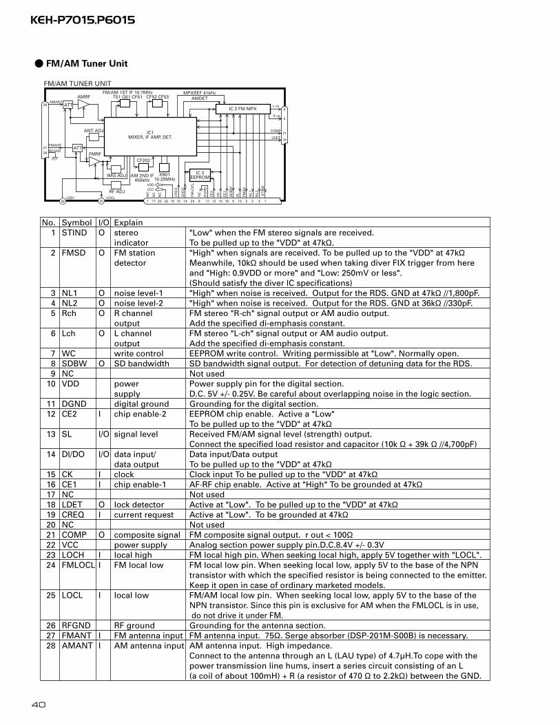
No. Symbol I/O Explain1 STIND O stereo "Low" when the FM stereo signals are received.
indicator To be pulled up to the "VDD" at 47kΩ.2 FMSD O FM station "High" when signals are received. To be pulled up to the "VDD" at 47kΩ
detector Meanwhile, 10kΩ should be used when taking diver FIX trigger from hereand "High: 0.9VDD or more" and "Low: 250mV or less".(Should satisfy the diver IC specifications)
3 NL1 O noise level-1 "High" when noise is received. Output for the RDS. GND at 47kΩ //1,800pF.4 NL2 O noise level-2 "High" when noise is received. Output for the RDS. GND at 36kΩ //330pF.5 Rch O R channel FM stereo "R-ch" signal output or AM audio output.
output Add the specified di-emphasis constant. 6 Lch O L channel FM stereo "L-ch" signal output or AM audio output.
output Add the specified di-emphasis constant. 7 WC write control EEPROM write control. Writing permissible at "Low". Normally open. 8 SDBW O SD bandwidth SD bandwidth signal output. For detection of detuning data for the RDS.9 NC Not used
10 VDD power Power supply pin for the digital section.supply D.C. 5V +/- 0.25V. Be careful about overlapping noise in the logic section.
11 DGND digital ground Grounding for the digital section. 12 CE2 I chip enable-2 EEPROM chip enable. Active a "Low"
To be pulled up to the "VDD" at 47kΩ13 SL I/O signal level Received FM/AM signal level (strength) output.
Connect the specified load resistor and capacitor (10k Ω + 39k Ω //4,700pF) 14 DI/DO I/O data input/ Data input/Data output
data output To be pulled up to the "VDD" at 47kΩ15 CK I clock Clock input To be pulled up to the "VDD" at 47kΩ16 CE1 I chip enable-1 AF·RF chip enable. Active at "High" To be grounded at 47kΩ17 NC Not used18 LDET O lock detector Active at "Low". To be pulled up to the "VDD" at 47kΩ19 CREQ I current request Active at "Low". To be grounded at 47kΩ20 NC Not used21 COMP O composite signal FM composite signal output. r out < 100Ω22 VCC power supply Analog section power supply pin.D.C.8.4V +/- 0.3V 23 LOCH I local high FM local high pin. When seeking local high, apply 5V together with "LOCL". 24 FMLOCL I FM local low FM local low pin. When seeking local low, apply 5V to the base of the NPN
transistor with which the specified resistor is being connected to the emitter. Keep it open in case of ordinary marketed models.
25 LOCL I local low FM/AM local low pin. When seeking local low, apply 5V to the base of the NPN transistor. Since this pin is exclusive for AM when the FMLOCL is in use,do not drive it under FM.
26 RFGND RF ground Grounding for the antenna section. 27 FMANT I FM antenna input FM antenna input. 75Ω. Serge absorber (DSP-201M-S00B) is necessary. 28 AMANT I AM antenna input AM antenna input. High impedance.
Connect to the antenna through an L (LAU type) of 4.7µH.To cope with thepower transmission line hums, insert a series circuit consisting of an L(a coil of about 100mH) + R (a resistor of 470 Ω to 2.2kΩ) between the GND.
IC 3EEPROM
FM/AM TUNER UNIT
28
27
FM/AM 1ST IF 10.7MHzT51 Q51 CF51 CF52 CF53
IC1MIXER, IF AMP, DET.
6
21
18LDET
COMP
2225 10 14 12 15 16 8 13 2 3 4
CF202
VDDVCC
DI/D
O
CE
2
CK
CE
1
SD
BW
SL
FMS
D
NL1
NL2
IC 2 FM MPX
AMANT
FMANT
ATT
ATT
AMRF
FMRF
IMG ADJ
RF ADJ
X90110.25MHz
ANT ADJ
LOCL23
LOCH
AMDETMPXREF 41kHz
AM 2ND IF450kHz
19
CR
EQ
11D
GN
D1
ST
IND
L ch
5R ch
924N
C
FMLO
CL
20177
NC
NC
WC
26 RFGND
- FM/AM Tuner Unit
41
KEH-P7015,P6015
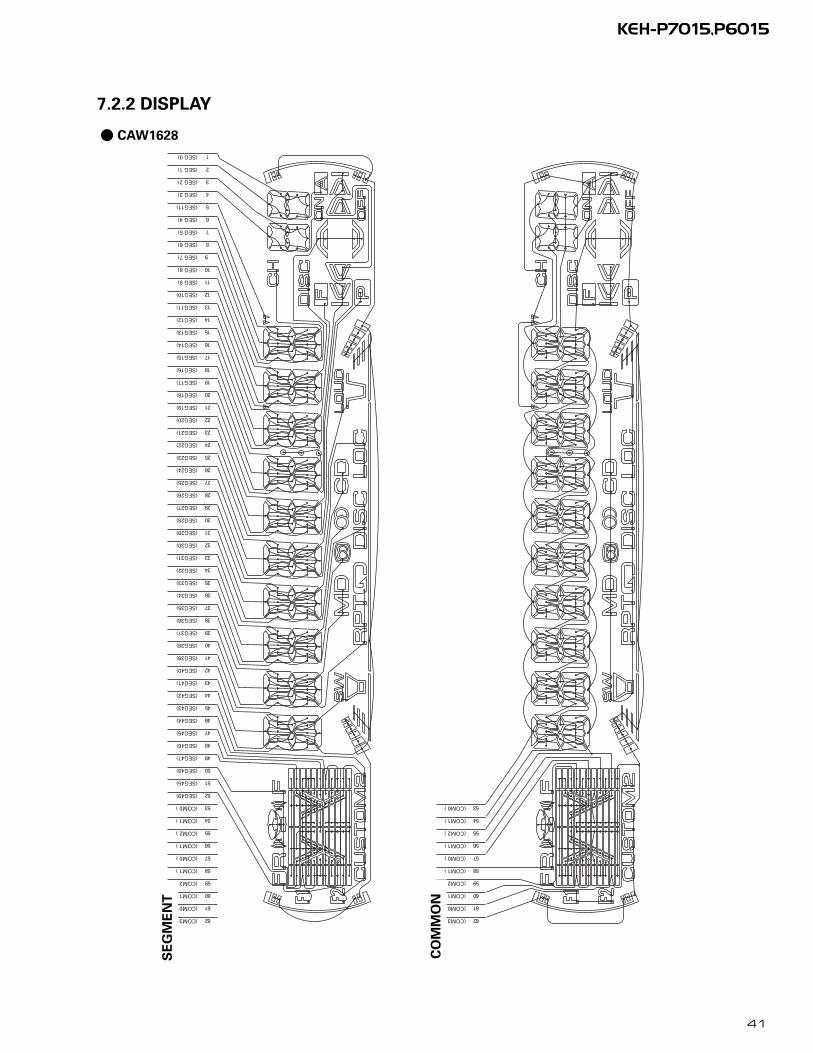
7.2.2 DISPLAY
(SEG11)
(SEG49)
(COM0 )
(COM1 )
(COM2 )
(COM1 )
(COM0 )
(COM1 )
(COM2 )
(COM1 )
(COM0 )
6
6
5
5
5
5
5
5
5
6
1
2
3
4
5
6
7
8
9
0
(COM3 )
(SEG45)
(SEG40)
(SEG41)
(SEG42)
(SEG43)
(SEG44)
(SEG45)
(SEG46)
(SEG47)
(SEG48)
(SEG30)
(SEG31)
(SEG32)
(SEG33)
(SEG34)
(SEG35)
(SEG36)
(SEG37)
(SEG38)
(SEG39)
(SEG20)
(SEG21)
(SEG22)
(SEG23)
(SEG24)
(SEG25)
(SEG26)
(SEG27)
(SEG28)
(SEG29)
(SEG10)
(SEG11)
(SEG12)
(SEG13)
(SEG14)
(SEG15)
(SEG16)
(SEG17)
(SEG18)
(SEG19)
(SEG 9)
(SEG 8)
(SEG 7)
(SEG 6)
(SEG 5)
(SEG 4)
(SEG 3)
(SEG 2)
(SEG 1)
(SEG 0)
(COM0 )
(COM1 )
(COM2 )
(COM1 )
(COM0 )
(COM1 )
(COM2 )
(COM1 )
(COM0 )
6
6
5
4
3
2
1
5
4
3
2
1
5
4
3
2
1
5
4
3
2
1
5
4
3
2
1
5
4
3
2
1
5
4
3
2
1
5
4
3
2
1
5
4
3
2
1
6
5
4
3
2
1
1
2
1
2
3
4
5
6
7
8
9
0
1
2
3
4
5
6
7
8
9
0
1
2
3
4
5
6
7
8
9
0
1
2
3
4
5
6
7
8
9
0
1
2
3
4
5
6
7
8
9
0
0
9
8
7
6
5
4
3
2
1
(COM3 )
SE
GM
EN
T
CO
MM
ON
- CAW1628

42
KEH-P7015,P6015
7.3 OPERATIONAL FLOW CHART
VDD=5V19pin
Power ON
bsens=L
asens=L
dsens=L
bsens93pin
asens92pin
dsens2pin
adpw←H22pinASENBO←H71pin
SWVDD←H23pin
Source keys operative
Completes power-on operation.(After that, proceed to each source operation)
SYSPW←H21pin
Startscommunication
with Grillemicrocomputer.
Source ON
300ms
300ms
In case of the above signal, the communication with Grille microcomputer may fail.If the time interval is not 300msec, the oscillator may be defective.
CSENSE77pin
2V<CSENS<4V
- 2V<CSENS<4V, Source returns to the original one(before you open). CD, MD and TAPE loading functions are available. Keys except for EJECT key are not available.
43
KEH-P7015,P6015
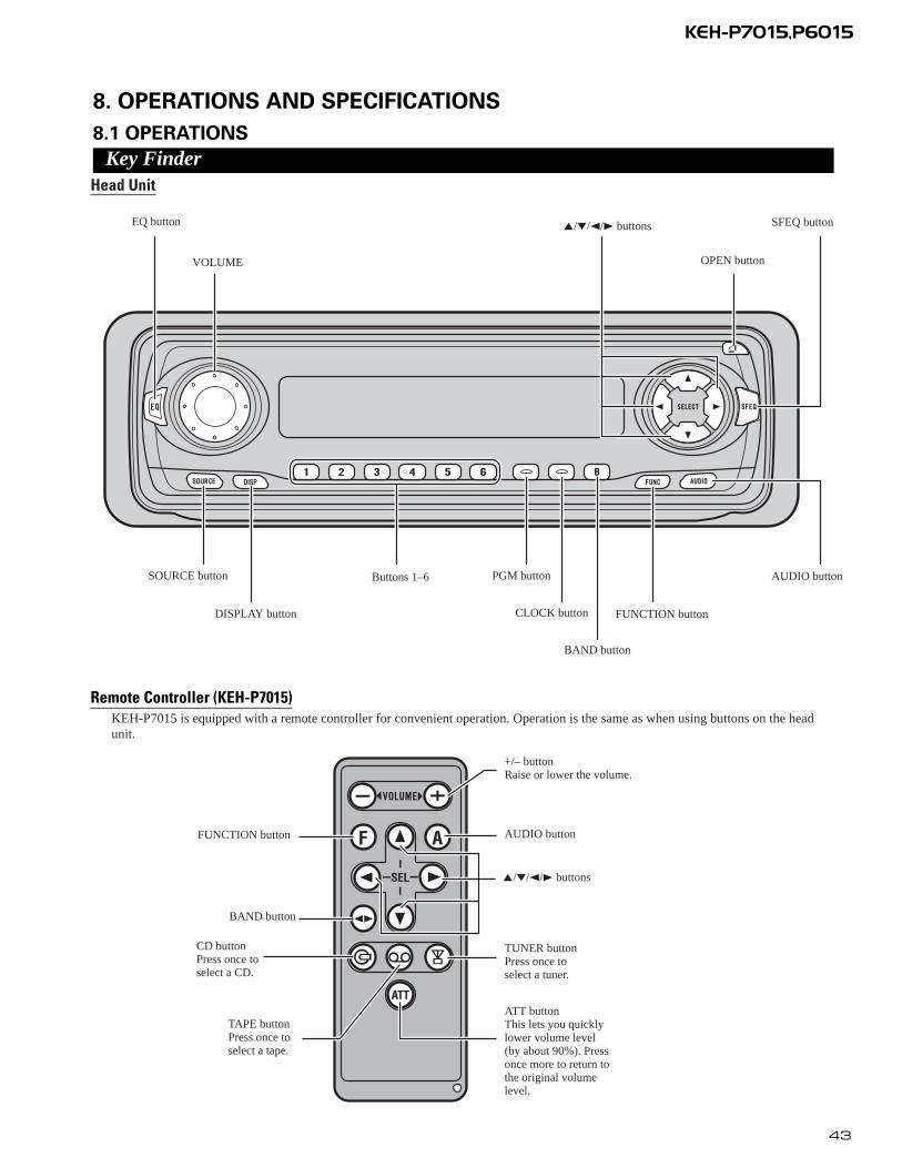
8. OPERATIONS AND SPECIFICATIONS
8.1 OPERATIONS
Key FinderHead Unit
Remote Controller (KEH-P7015)KEH-P7015 is equipped with a remote controller for convenient operation. Operation is the same as when using buttons on the headunit.
EQ button
VOLUME OPEN button
AUDIO button
SFEQ button5/∞/2/3 buttons
BAND button
Buttons 1–6
FUNCTION buttonDISPLAY button CLOCK button
PGM buttonSOURCE button
+/– buttonRaise or lower the volume.
AUDIO button
5/∞/2/3 buttons
TUNER buttonPress once toselect a tuner.
ATT buttonThis lets you quicklylower volume level(by about 90%). Pressonce more to return tothe original volumelevel.
BAND button
CD buttonPress once toselect a CD.
TAPE buttonPress once toselect a tape.
FUNCTION button

44
KEH-P7015,P6015
Bas
ic O
pera
tion
To L
iste
n to
Mus
icT
he f
ollo
win
g ex
plai
ns th
e in
itial
ope
ratio
ns r
equi
red
befo
re y
ou c
an li
sten
to m
usic
.
Not
e:•
Loa
ding
a c
asse
tte in
this
pro
duct
.
1.Se
lect
the
des
ired
sou
rce.
(e.
g. T
uner
)
7H
ead
Uni
tE
ach
pres
s of
the
SOU
RC
E b
utto
n se
lect
s th
e de
sire
d so
urce
in th
e fo
llow
ing
orde
r:C
D p
laye
r (o
ne d
isc
only
) =
TV
=T
uner
=C
asse
tte P
laye
r =
Mul
ti-C
D p
laye
r =
Ext
erna
l Uni
t =A
UX
Not
e: •E
xter
nal U
nit r
efer
s to
a P
ione
er p
rodu
ct (
such
as
one
avai
labl
e in
the
futu
re)
that
, alth
ough
inco
m-
patib
le a
s a
sour
ce, e
nabl
es c
ontr
ol o
f ba
sic
func
tions
by
this
pro
duct
. Onl
y on
e E
xter
nal U
nit c
anbe
con
trol
led
by th
is p
rodu
ct.
•In
the
follo
win
g ca
ses,
the
soun
d so
urce
will
not
cha
nge:
*W
hen
a pr
oduc
t cor
resp
ondi
ng to
eac
h so
urce
is n
ot c
onne
cted
to th
is p
rodu
ct.
*W
hen
no ta
pe is
set
in th
is p
rodu
ct.
*W
hen
no m
agaz
ine
is s
et in
the
Mul
ti-C
D p
laye
r.*
Whe
n th
e A
UX
(ex
tern
al in
put)
is s
et to
OFF
. *
Whe
n no
dis
c is
set
in th
e C
D p
laye
r (o
ne d
isc
only
).•
Whe
n th
is p
rodu
ct’s
blu
e/w
hite
lead
is c
onne
cted
to th
e ca
r’s
Aut
o-an
tenn
a re
lay
cont
rol t
erm
inal
,th
e ca
r’s
Aut
o-an
tenn
a ex
tend
s w
hen
this
pro
duct
’s s
ourc
e is
sw
itche
d O
N. T
o re
trac
t the
ant
enna
,sw
itch
the
sour
ce O
FF.
Eac
h pr
ess
chan
ges
the
Sour
ce ..
.
2.R
aise
or
low
er t
he v
olum
e.
Rol
ling
the
VO
LU
ME
cha
nges
the
volu
me
leve
l.
Not
e:
•R
oll c
lock
wis
e to
rai
se th
e vo
lum
e le
vel.
•R
oll c
ount
ercl
ockw
ise
to lo
wer
the
volu
me
leve
l.
3.Tu
rn t
he s
ourc
e O
FF.
Hol
d fo
r 1
seco
nd
Bas
ic O
pera
tion
of T
uner
Res
et th
e A
M tu
ning
ste
p fr
om 9
kH
z (t
he f
acto
ry p
rese
t ste
p) to
10
kHz
whe
n us
ing
the
tune
r in
Nor
th, C
entr
al o
r So
uth
Am
eric
a.
Man
ual a
nd S
eek
Tuni
ng
•Y
ou c
an s
elec
t th
e tu
ning
met
hod
by c
hang
ing
the
leng
th o
fti
me
you
pres
s th
e 2
/3bu
tton
.
Man
ual T
unin
g (s
tep
by s
tep)
0.5
seco
nds
or le
ss
Seek
Tun
ing
0.5
seco
nds
or m
ore
Not
e:•
If y
ou c
ontin
ue p
ress
ing
the
butto
n fo
r lo
nger
than
0.5
sec
onds
, you
can
ski
pbr
oadc
astin
g st
atio
ns. S
eek
Tun
ing
star
ts a
s so
on a
s yo
u re
leas
e th
e bu
tton.
•St
ereo
indi
cato
r “
” lig
hts
whe
n a
ster
eo s
tatio
n is
sel
ecte
d.
Pres
et N
umbe
r Ind
icat
or
Ban
d F1 (
FM1)
=F2
(FM
2)
=F3
(FM
3) =
AM
Ban
d In
dica
tor
Freq
uenc
y In
dica
tor
Pres
et T
unin
g
•Y
ou c
an m
emor
ize
broa
dcas
t st
atio
ns in
but
tons
1 th
roug
h 6
for
easy
, one
-tou
ch s
tati
on r
ecal
l.
Pres
et s
tatio
n re
call
2 se
cond
s or
less
Bro
adca
st s
tatio
n pr
eset
mem
ory
2 se
cond
s or
mor
e
Not
e:•
Up
to 1
8 FM
sta
tions
(6
in F
1 (F
M1)
, F2
(FM
2) a
nd F
3(F
M3)
) an
d 6
AM
sta
tions
can
be
stor
ed in
mem
ory.
•Y
ou c
an a
lso
use
the
5or
∞bu
ttons
to r
ecal
l bro
adca
st s
ta-
tions
mem
oriz
ed in
but
tons
1 th
roug
h 6.

45
KEH-P7015,P6015
Bas
ic O
pera
tion
Bas
ic O
pera
tion
of C
asse
tte P
laye
r
Not
e:•
Be
sure
to c
lose
the
fron
t pan
el a
fter
load
ing
or e
ject
ing
a ca
sset
te.
Cass
ette
Loa
ding
Slo
t
Not
e:•
Do
not i
nser
t any
thin
g ot
her
than
a c
asse
tte in
toth
e C
asse
tte L
oadi
ng S
lot.
Play
Tim
e In
dica
tor
Not
e:•
The
con
tinuo
us p
layb
ack
time
coun
t sta
rts
at 0
0’00
” at
the
follo
win
g tim
es.
*W
hen
a ta
pe is
inse
rted
.*
Whe
n th
e ta
pe d
irec
tion
is c
hang
ed.
*W
hen
you
rew
ind
the
tape
sid
e cu
rren
tly p
layi
ng b
ack
to th
e be
ginn
ing.
•T
he c
ontin
uous
pla
ybac
k tim
e co
unt i
s ha
lted
whe
n fa
st-f
orw
ardi
ng/r
ewin
ding
and
whi
le th
eM
usic
Sea
rch
func
tion
is o
pera
ting.
Ejec
t Not
e:•
The
Tap
e fu
nctio
n ca
n be
turn
ed O
N/O
FF w
ith th
e ca
sset
te ta
pere
mai
ning
in th
is p
rodu
ct.
Ope
n Not
e:•
Use
to o
pen
the
fron
t pan
el w
hen
load
ing
or e
ject
ing
a ca
sset
te.
(The
illu
stra
tion
on th
e ri
ght s
how
s th
e fr
ont p
anel
ope
n.)
Fast
For
war
d/Re
win
d an
d M
usic
Sea
rch
•E
ach
pres
s of
the
3bu
tton
sel
ects
Fas
t F
orw
ard
or F
orw
ard-
Mus
icSe
arch
.FF
(Fa
st F
orw
ard)
=F-
MS
(For
war
d-M
usic
Sea
rch)
=N
orm
al P
layb
ack
•E
ach
pres
s of
the
2bu
tton
sel
ects
Rew
ind
or R
ewin
d-M
usic
Sea
rch.
RE
W (
Rew
ind)
=R
-MS
(Rew
ind-
Mus
ic S
earc
h) =
Nor
mal
Pla
ybac
k
Not
e:•
Fast
For
war
d/R
ewin
d an
d M
usic
Sea
rch
can
be c
ance
led
by p
ress
ing
the
BA
ND
butto
n.
Dir
ectio
n Ch
ange
Dir
ectio
n In
dica
tor

46
KEH-P7015,P6015
Bas
ic O
pera
tion
Bas
ic O
pera
tion
of M
ulti-
CD P
laye
rT
his
prod
uct c
an c
ontr
ol a
Mul
ti-C
D p
laye
r (s
old
sepa
rate
ly).
Corr
espo
ndin
g D
ispl
ay In
dica
tions
and
But
tons
T
his
prod
uct’s
dis
play
fea
ture
s K
ey G
uida
nce
Indi
cato
rs. T
hese
ligh
t to
indi
cate
whi
ch o
fth
e 5
/∞/2
/3, F
UN
CT
ION
and
AU
DIO
but
tons
you
can
use
. Whe
n yo
u’re
in th
eFu
nctio
n M
enu,
Det
aile
d Se
tting
Men
u, I
nitia
l Set
ting
Men
u o
r A
udio
Men
u, th
ey a
lso
mak
e it
easy
to s
ee w
hich
5/∞
/2/3
butto
ns y
ou c
an u
se to
sw
itch
func
tions
ON
/OFF
,sw
itch
repe
at s
elec
tions
and
per
form
oth
er o
pera
tions
.In
dica
tor
and
corr
espo
ndin
g bu
ttons
are
sho
wn
belo
w.
7H
ead
Uni
t7
Rem
ote
Cont
rolle
r7
Dis
play
Whe
n 1
is li
t in
the
disp
lay,
per
form
app
ropr
iate
ope
ratio
ns w
ith th
e z
butto
ns.
Whe
n 2
is li
t in
the
disp
lay,
it in
dica
tes
that
you
are
in th
e Fu
nctio
n M
enu,
Det
aile
dSe
tting
Men
u or
Ini
tial S
ettin
g M
enu.
You
can
sw
itch
betw
een
each
of
thes
e m
enus
and
betw
een
diff
eren
t mod
es in
the
men
us u
sing
but
ton
xon
the
head
uni
t or
rem
ote
con-
trol
ler.
Whe
n 3
is li
t in
the
disp
lay,
it in
dica
tes
you
are
in th
e A
udio
Men
u. Y
ou c
an s
witc
hbe
twee
n m
odes
in th
e A
udio
Men
u us
ing
butto
n c
on th
e he
ad u
nit o
r re
mot
e co
ntro
ller.
Ente
ring
the
Func
tion
Men
uT
he F
unct
ion
Men
u le
ts y
ou o
pera
te s
impl
e fu
nctio
ns f
or e
ach
sour
ce.
Not
e:•
Aft
er e
nter
ing
the
Func
tion
Men
u, if
you
do
not p
erfo
rm a
n op
erat
ion
with
in a
bout
30
seco
nds,
the
Func
tion
Men
u is
aut
omat
ical
ly c
ance
led.
1.Se
lect
the
des
ired
mod
e in
the
Fun
ctio
n M
enu.
Con
tinu
ed o
verl
eaf.
Eac
h pr
ess
chan
ges
the
Mod
e ...
z
cx
Play
Tim
e In
dica
tor
Trac
k N
umbe
r Ind
icat
orD
isc
Num
ber I
ndic
ator
Dis
c N
umbe
r Sea
rch
(for 6
-Dis
c, 1
2-D
isc
type
s)
•Y
ou c
an s
elec
t di
scs
dire
ctly
wit
h th
e 1
to 6
but
tons
. Jus
t pr
ess
the
num
-be
r co
rres
pond
ing
to t
he d
isc
you
wan
t to
list
en t
o.
Not
e:•
Whe
n a
12-D
isc
Mul
ti-C
D P
laye
r is
con
nect
ed a
nd y
ou w
ant t
o se
lect
dis
c 7
to 1
2, p
ress
the
1 to
6 b
utto
ns f
or 2
sec
onds
.
Not
e:•
The
Mul
ti-C
D p
laye
r m
ay p
erfo
rm a
pre
para
tory
ope
ratio
n, s
uch
as v
erif
ying
the
pres
ence
of
a di
sc o
r re
adin
g di
sc in
form
atio
n, w
hen
the
pow
er is
turn
ed O
N o
r a
new
dis
c is
sel
ecte
d fo
rpl
ayba
ck. “
RE
AD
Y”
is d
ispl
ayed
.•
If th
e M
ulti-
CD
pla
yer
cann
ot o
pera
te p
rope
rly,
an
erro
r m
essa
ge s
uch
as “
ER
RO
R-1
4” is
disp
laye
d. R
efer
to th
e M
ulti-
CD
pla
yer
owne
r’s
man
ual.
•If
ther
e ar
e no
dis
cs in
the
Mul
ti-C
D p
laye
r m
agaz
ine,
“N
O D
ISC
” is
dis
play
ed.
Trac
k Se
arch
and
Fas
t For
war
d/Re
vers
e
•Y
ou c
an s
elec
t be
twee
n T
rack
Sea
rch
or F
ast
For
war
d/R
ever
se b
y pr
essi
ng t
he 2
/3bu
tton
for
a di
ffer
ent
leng
th o
f ti
me.
Tra
ck S
earc
h0.
5 se
cond
s or
less
Fast
For
war
d/R
ever
seC
ontin
ue p
ress
ing
Dis
c Se
arch

47
KEH-P7015,P6015
2.O
pera
te a
mod
e. (
e.g.
Rep
eat
Pla
y)
3.C
ance
l the
Fun
ctio
n M
enu.
The
but
ton
used
and
the
oper
atio
n it
perf
orm
s ar
ein
dica
ted
by th
e ke
y gu
idan
ce in
dica
tor.
Pres
s th
e 5
butto
n to
sw
itch
the
key
guid
ance
indi
cato
r O
N,
and
the
∞bu
tton
to s
witc
h it
OFF
.
Bas
ic O
pera
tion
Ente
ring
the
Det
aile
d Se
tting
Men
uIn
the
Det
aile
d Se
tting
Men
u, y
ou c
an o
pera
te c
onve
nien
t, co
mpl
ex f
unct
ions
for
eac
hso
urce
.
1.E
nter
the
Det
aile
d Se
ttin
g M
enu.
2.Se
lect
the
des
ired
mod
e.
3.O
pera
te a
mod
e.
4.C
ance
l the
Det
aile
d Se
ttin
g M
enu.
Not
e:•
You
can
can
cel t
he D
etai
led
Setti
ng M
enu
by p
ress
ing
the
FUN
CT
ION
but
ton
agai
n fo
r 2
seco
nds.
Eac
h pr
ess
chan
ges
the
Mod
e ...
Hol
d fo
r 2
seco
nds

48
KEH-P7015,P6015
- CONNECTION DIAGRAM
16.B
lue/
whi
teTo
syst
emco
ntro
lter
min
alof
the
pow
eram
por
Aut
o-an
tenn
are
lay
cont
rolt
erm
inal
(max
.30
0mA
12V
DC
).
14.C
onne
ctin
gco
rds
with
RC
Api
npl
ugs
(sol
dse
para
tely
)
17.S
yste
mre
mot
eco
ntro
l
24.R
igh
t
19.W
hite
21.G
ray
20.W
hite
/bla
ck
26.G
reen
27.G
reen
/bla
ck
22.G
ray/
blac
k
28.V
iole
t
29.V
iole
t/bla
ck
18.F
ront
spea
ker
23.L
eft
31.P
erfo
rmth
ese
conn
ectio
nsw
hen
usin
ga
diff
eren
tam
p(s
old
sepa
rate
ly).
30.W
itha
2sp
eake
rsy
stem
,do
notc
onne
ctan
ythi
ngto
the
spea
ker
lead
sth
atar
eno
tco
nnec
ted
tosp
eake
rs.
9.Y
ello
wTo
term
inal
alw
ays
supp
lied
with
pow
erre
gard
less
ofig
nitio
nsw
itch
posi
tion.
12.B
lack
(gro
und)
Tove
hicl
e(m
etal
)bo
dy.
10.R
edTo
elec
tric
term
inal
cont
rolle
dby
igni
tion
switc
h(1
2V
DC
)O
N/O
FF.
11.O
rang
e/w
hite
Tolig
htin
gsw
itch
term
inal
.
25.R
ear
spea
ker
orSu
bwoo
fer
25.R
ear
spea
ker
orSu
bwoo
fer
18.F
ront
spea
ker
15.P
ower
amp
(sol
dse
para
tely
)
18.F
ront
spea
ker
18.F
ront
spea
ker
25.R
ear
spea
ker
orSu
bwoo
fer
25.R
ear
spea
ker
orSu
bwoo
fer15
.Pow
eram
p(s
old
sepa
rate
ly)
32.
13.F
use
8.IP
-BU
Sca
ble
6.IP
-BU
Sin
put(
Blu
e)
3.T
his
Prod
uct
5.A
nten
naja
ck
4.R
ear
orSu
bwoo
fer
outp
ut
1.Fr
onto
utpu
t
15cm
7.M
ulti-
CD
play
er(s
old
sepa
rate
ly)
Not
e:W
hen
asu
bwoo
fer
isco
nnec
ted
toth
isun
itin
stea
dof
are
arsp
eake
r,ch
ange
the
rear
outp
utse
tting
inth
eIn
itial
Setti
ng.(
Ref
erto
the
Ope
ratio
nM
anua
l.)T
hesu
bwoo
fer
outp
utof
this
unit
ism
onau
ral.
2.T
his
RC
Api
nja
ckis
avai
labl
eon
lyfo
rK
EH
-P70
15.

49
KEH-P7015,P6015
8.2 SPECIFICATIONS
GeneralPower source .......... 14.4 V DC (10.8 – 15.1 V allowable)Grounding system ........................................ Negative typeMax. current consumption ...................................... 10.0 ADimensions
(DIN) (chassis) ...... 178 (W) × 50 (H) × 157 (D) mm(nose) .......... 188 (W) × 58 (H) × 19 (D) mm
(D) (chassis) ...... 178 (W) × 50 (H) × 162 (D) mm(nose) .......... 170 (W) × 46 (H) × 14 (D) mm
Weight ...................................................................... 1.4 kgBackup current ............................................................5mA
AmplifierContinuous power output is 22 W per channel min. into 4ohms, both channels driven 50 to 15,000 Hz with no morethan 5% THD.Maximum power output ...................................... 50 W × 4
50 W × 2 ch/4 Ω + 70 W × 1 ch/2 Ω (for Subwoofer)Load impedance
...................... 4 Ω (4 – 8 Ω [2 Ω for 1 ch] allowable)Preout maximum output level/
output impedance .................................... 2.2 V/1 kΩEqualizer (3-Band Parametric Equalizer)
(Low) .......................... Frequency: 40/80/100/160 HzQ Factor: 0.35/0.59/0.95/1.15
(+6 dB when boosted)Level: ±12 dB
(Mid) .......................... Frequency: 200/500/1k/2k HzQ Factor: 0.35/0.59/0.95/1.15
(+6 dB when boosted)Level: ±12 dB
(High) ................ Frequency: 3.15k/8k/10k/12.5k HzQ Factor: 0.35/0.59/0.95/1.15
(+6 dB when boosted)Level: ±12 dB
Loudness contour(Low) .................. +3.5 dB (100 Hz), +3 dB (10 kHz)(Mid) ................ +10 dB (100 Hz), +6.5 dB (10 kHz)(High) ................ +11 dB (100 Hz), +11 dB (10 kHz)
(volume: –30 dB)Tone controls
(Bass) .......................... Frequency: 40/63/100/160 HzLevel: ±12 dB
(Treble) .................. Frequency: 2.5k/4k/6.3k/10k HzLevel: ±12 dB
Subwoofer outputFrequency ............................................ 50/80/125 HzSlope ........................................................ –12 dB/oct.Gain ................................................................ ±12 dB
Cassette playerTape ........................ Compact cassette tape (C-30 – C-90)Tape speed ........ 4.76 cm/sec.(+0.14cm/sec.,-0.05cm/sec.)Fast forward/rewinding time .... Approx. 100 sec. for C-60Wow & flutter .......................................... 0.09% (WRMS)Frequency response ...................... 30 – 16,000 Hz (±3 dB)Stereo separation ...................................................... 45 dBSignal-to-noise ratio...................... 61 dB (IEC-A network)
FM tunerFrequency range ...................................... 87.5 – 108 MHzUsable sensitivity ...................................................... 9 dBf
(0.8 µV/75 Ω, mono, S/N: 30 dB)50 dB quieting sensitivity ........................................ 15 dBf
(1.5 µV/75 Ω, mono)Signal-to-noise ratio ...................... 70 dB (IEC-A network)Distortion .......................... 0.3% (at 65 dBf, 1 kHz, stereo)Frequency response ...................... 30 – 15,000 Hz (±3 dB)Stereo separation .......................... 40 dB (at 65 dBf, 1 kHz)
AM tunerFrequency range ........................ 531 – 1,602 kHz (9 kHz)
530 – 1,640 kHz (10 kHz)Usable sensitivity .............................. 18 µV (S/N: 20 dB)Selectivity .................................................. 50 dB (±9 kHz)
50 dB (±10 kHz)
Note:• Specifications and the design are subject to possi-
ble modification without notice due to improve-ments.