orthopantomograph® op100 & op100 d orthoceph ... electrical operation, schematics and layouts...
TRANSCRIPT

Orthopantomograph® OP100 & OP100 DOrthoceph® OC100 & OC100 DElectrical Operation & Wiring Manual
5139519-100 rev 3
Approved: Ukkonen Juha-Pekka 2006-10-11 09:53Reviewed: Vartia Jussi 2006-10-03 08:31 Approved
See
PD
M s
yste
m to
det
erm
ine
the
stat
us o
f thi
s do
cum
ent.
Prin
ted
out:
2015
-04-
09 1
7:21
:03
5139519-100TPH-1, 3
Cop
yrig
ht ©
200
6 by
Pal
oDE
x G
roup
Oy.
All
right
s re
serv
ed.

Approved: Ukkonen Juha-Pekka 2006-10-11 09:53Reviewed: Vartia Jussi 2006-10-03 08:31 Approved
See
PD
M s
yste
m to
det
erm
ine
the
stat
us o
f thi
s do
cum
ent.
Prin
ted
out:
2015
-04-
09 1
7:21
:03
5139519-100TPH-1, 3
Cop
yrig
ht ©
200
6 by
Pal
oDE
x G
roup
Oy.
All
right
s re
serv
ed.

Copyright Code: 5139519-100 rev 3 Date: 22 September 2006
Copyright © 09/2006 by PaloDEx Group Oy. All rights reserved.
Manufactured by Instrumentarium DentalP.O. Box 20FI-04301 TuusulaFINLANDTel. +358 45 7882 2000Fax. +358 45 7882 2506
Orthopantomograph® and Orthoceph® are registered trademarks ofInstrumentarium Dental. U.S. patents 4,641,336; 5,016,264; 5,425,065,5,444,754, 6,731,717 and 6,829,326. German patent 4,344,745. Finnishpatents 112594 and 114383.
Orthopantomograph® and Orthoceph® are registered trademarks ofInstrumentarium Dental. U.S. patents 4,641,336; 5,016,264; 5,425,065,5,444,754, 6,731,717 and 6,829,326. German patent 4,344,745. Finnishpatents 112594 and 114383. Windows® is trademark of MicrosoftCorporation in the United States of America and other countries. Pentium®
is a registered trademark of Intel Corporation. Iomega® Jaz® is aregistered trademark of Iomega Corp.
Documentation, trademark and the software are copyrighted with allrights reserved. Under the copyright laws the documentation may not becopied, photocopied, reproduced, translated, or reduced to any electronicmedium or machine readable form in whole or part, without the priorwritten permission of Instrumentarium Dental.
The original language of this manual is English.
Instrumentarium Dental reserves the right to make changes inspecification and features shown herein, or discontinue the productdescribed at any time without notice or obligation. Contact yourInstrumentarium Dental representative for the most current information.
For service, contact your local distributor.
Approved: Ukkonen Juha-Pekka 2006-10-11 09:53Reviewed: Vartia Jussi 2006-10-03 08:31 Approved
See
PD
M s
yste
m to
det
erm
ine
the
stat
us o
f thi
s do
cum
ent.
Prin
ted
out:
2015
-04-
09 1
7:21
:03
5139519-100TPH-1, 3
Cop
yrig
ht ©
200
6 by
Pal
oDE
x G
roup
Oy.
All
right
s re
serv
ed.

Approved: Ukkonen Juha-Pekka 2006-10-11 09:53Reviewed: Vartia Jussi 2006-10-03 08:31 Approved
See
PD
M s
yste
m to
det
erm
ine
the
stat
us o
f thi
s do
cum
ent.
Prin
ted
out:
2015
-04-
09 1
7:21
:03
5139519-100TPH-1, 3
Cop
yrig
ht ©
200
6 by
Pal
oDE
x G
roup
Oy.
All
right
s re
serv
ed.

Table of Contents
ApprRevi
See
PD
M s
yste
m to
det
erm
ine
the
stat
us o
f thi
s do
cum
ent.
Prin
ted
out:
2015
-04-
09 1
7:21
:03
Cop
yrig
ht ©
200
6 by
Pal
oDE
x G
roup
Oy.
All
right
s re
serv
ed.
1 Electrical operation, schematics and layouts .................................................... 11.1 Electrical block diagrams.............................................................................................................................11.2 Wiring diagram .................................................................................................................................................21.3 Primary electronics .........................................................................................................................................21.4 Power supply board (CODE 60113)..........................................................................................................2
1.4.1 Line voltage jumper...................................................................................................................................... 31.4.2 High voltage section...................................................................................................................................... 31.4.3 Low voltage section....................................................................................................................................... 3
1.5 C167 CORE MODULE (CODE 60244)........................................................................................................41.6 Digital I/O Board (60229) ..............................................................................................................................51.7 Interface Board (CODE 60166) ...................................................................................................................81.8 X-ray generator ................................................................................................................................................91.9 Filament Control Board (CODE 60114) ................................................................................................101.10 Inverter board (CODE 60115)..................................................................................................................131.11 Tube head assembly (CODE 66360) .....................................................................................................151.12 Automatic Exposure Control (AEC) Board
(CODE 60122) ..................................................................................................................................................151.13 PAN AEC terminal Board (CODE 60247)..............................................................................................16
1.13.1 PAN Automatic Exposure Control (AEC)..............................................................................................171.14 Panorama & cephalometric camera
(digi only) ...........................................................................................................................................................181.15 Camera power supply Board (CODE 60197)
(DIGI ONLY) .......................................................................................................................................................191.16 Ceph terminal Board (Code 60191)
(DIGI ONLY) .......................................................................................................................................................201.16.1 Nasio -frequency adjustment .................................................................................................................21
1.17 Ceph head Board (CODE 60243)(DIGI ONLY) .......................................................................................................................................................22
1.18 Beam alignment Board (CODE 60249)(DIGI ONLY) .......................................................................................................................................................22
1.19 PCI Board (CODE 60187) AND fibre cable (CODE 69061)(DIGI ONLY) .......................................................................................................................................................24
2 Other components .................................................................................................272.1 CONTROL PANELS
(CODE 64105 FOR FILM AND 64104 FOR DIGITAL) .....................................................................................................................................27
2.2 Patient positioning panel (CODE 60218).............................................................................................282.3 Head support lock ........................................................................................................................................292.4 Halogen positioning lights ........................................................................................................................292.5 Ortho Trans positioning lights.................................................................................................................302.6 FH laser light (digi only) ..............................................................................................................................302.7 Remote exposure control..........................................................................................................................302.8 Ceph soft tissue display (film only) ........................................................................................................312.9 Ceph soft tissue automatic adjustment
(digi only) ...........................................................................................................................................................312.10 Ceph nose support .......................................................................................................................................31
d
5139519-100 rev 3 Instrumentarium Dental ioved: Ukkonen Juha-Pekka 2006-10-11 09:53ewed: Vartia Jussi 2006-10-03 08:31 Approve
5139519-100TPH-1, 3

ApprRevi
See
PD
M s
yste
m to
det
erm
ine
the
stat
us o
f thi
s do
cum
ent.
Prin
ted
out:
2015
-04-
09 1
7:21
:03
Cop
yrig
ht ©
200
6 by
Pal
oDE
x G
roup
Oy.
All
right
s re
serv
ed.
2.11 Up/down panel (CODE 60193) + UP/DOWN SWITCH (CODE 60143)(DIGI ONLY) .......................................................................................................................................................31
2.12 Cephalostat L/R coding..............................................................................................................................323 Overview of Digital Image Capture ....................................................................33
3.1 Operation Overview.....................................................................................................................................333.2 Digital parts overview.................................................................................................................................39
4 List of documents...................................................................................................414.1 Common film and digital unit documents ........................................................................................414.2 Film unit documents....................................................................................................................................414.3 Digital unit documents ...............................................................................................................................41
d
ii Instrumentarium Dental 5139519-100 rev 3oved: Ukkonen Juha-Pekka 2006-10-11 09:53ewed: Vartia Jussi 2006-10-03 08:31 Approve
5139519-100TPH-1, 3

1 Electrical operation, schematics and layouts
ApprRevi
See
PD
M s
yste
m to
det
erm
ine
the
stat
us o
f thi
s do
cum
ent.
Prin
ted
out:
2015
-04-
09 1
7:21
:03
Cop
yrig
ht ©
200
6 by
Pal
oDE
x G
roup
Oy.
All
right
s re
serv
ed.
1 Electrical operation, schematics and layouts
1.1 ELECTRICAL BLOCK DIAGRAMS
d
5139519-100 rev 3 Instrumentarium Dental 1oved: Ukkonen Juha-Pekka 2006-10-11 09:53ewed: Vartia Jussi 2006-10-03 08:31 Approve
5139519-100TPH-1, 3

1 Electrical operation, schematics and layouts
ApprRevi
See
PD
M s
yste
m to
det
erm
ine
the
stat
us o
f thi
s do
cum
ent.
Prin
ted
out:
2015
-04-
09 1
7:21
:03
Cop
yrig
ht ©
200
6 by
Pal
oDE
x G
roup
Oy.
All
right
s re
serv
ed.
1.2 WIRING DIAGRAM
Copies of OP100 Wiring diagrams, see section “List of Documents”.
1.3 PRIMARY ELECTRONICS
1-phase electric power is fed through a 3-pole cable to the column wherethe cable goes inside the right side groove to the vertical carriage(connectors X101 and X122). Line filter is located under the lower shelf.Line filter ground is connected to the incoming 3-pole cable ground. Flatconnectors or fixed screws are used. The line filter type with CE-marking:type S-124-10 or NM-240-10 (code 69025).
WARNING!Always make sure OP100 D has a good protective ground.
Main switch with power on indicator light is located under the verticalcarriage. Main fuses are located below the vertical carriage. Both F1 andF2 are slow blow type for incoming main voltage 230 VAC:
NOTE!In USA/Canada 15AT fuses are used also with 230 VAC rating.
1.4 POWER SUPPLY BOARD (CODE 60113)
Power Supply Board rectifies AC voltages and filters the unregulated DCvoltages. Power Supply Board consists of two main parts: low voltage andhigh voltage parts.
d
2 Instrumentarium Dental 5139519-100 rev 3oved: Ukkonen Juha-Pekka 2006-10-11 09:53ewed: Vartia Jussi 2006-10-03 08:31 Approve
5139519-100TPH-1, 3
1 Electrical operation, schematics and layouts
ApprRevi
See
PD
M s
yste
m to
det
erm
ine
the
stat
us o
f thi
s do
cum
ent.
Prin
ted
out:
2015
-04-
09 1
7:21
:03
Cop
yrig
ht ©
200
6 by
Pal
oDE
x G
roup
Oy.
All
right
s re
serv
ed.
WARNING!Voltages in high voltage part of the power supply board can be deadly.The peak-to-peak voltage level normally exceeds 600 V.
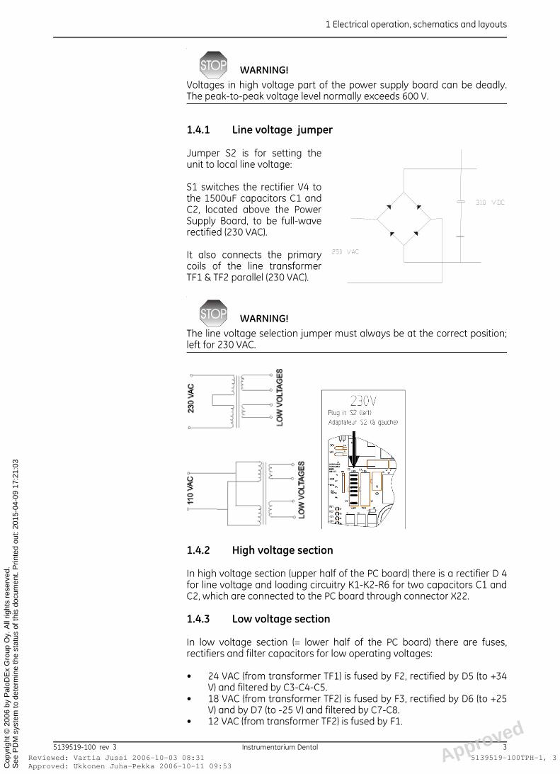
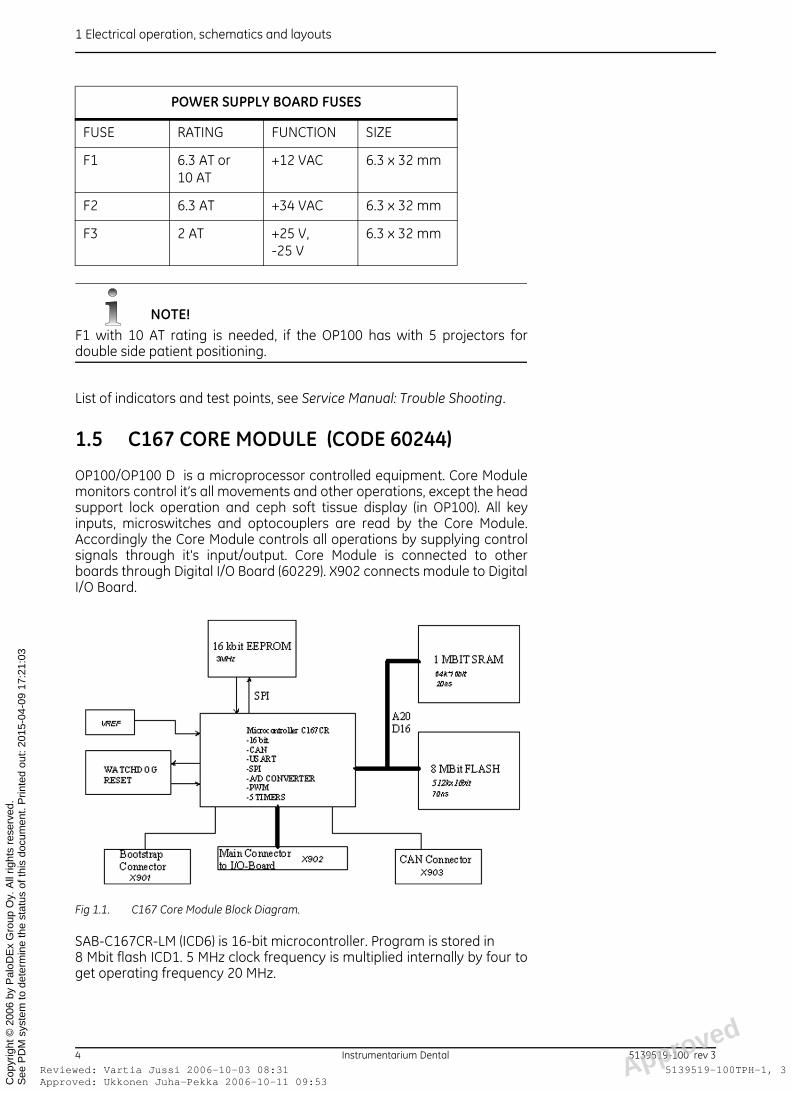
1.4.1 Line voltage jumper
Jumper S2 is for setting theunit to local line voltage:
S1 switches the rectifier V4 tothe 1500uF capacitors C1 andC2, located above the PowerSupply Board, to be full-waverectified (230 VAC).
It also connects the primarycoils of the line transformerTF1 & TF2 parallel (230 VAC).
WARNING!The line voltage selection jumper must always be at the correct position;left for 230 VAC.
1.4.2 High voltage section
In high voltage section (upper half of the PC board) there is a rectifier D 4for line voltage and loading circuitry K1-K2-R6 for two capacitors C1 andC2, which are connected to the PC board through connector X22.
1.4.3 Low voltage section
In low voltage section (= lower half of the PC board) there are fuses,rectifiers and filter capacitors for low operating voltages:
• 24 VAC (from transformer TF1) is fused by F2, rectified by D5 (to +34V) and filtered by C3-C4-C5.
• 18 VAC (from transformer TF2) is fused by F3, rectified by D6 (to +25V) and by D7 (to -25 V) and filtered by C7-C8.
• 12 VAC (from transformer TF2) is fused by F1.d
5139519-100 rev 3 Instrumentarium Dental 3
oved: Ukkonen Juha-Pekka 2006-10-11 09:53ewed: Vartia Jussi 2006-10-03 08:31 Approve
5139519-100TPH-1, 3
1 Electrical operation, schematics and layouts
ApprRevi
See
PD
M s
yste
m to
det
erm
ine
the
stat
us o
f thi
s do
cum
ent.
Prin
ted
out:
2015
-04-
09 1
7:21
:03
Cop
yrig
ht ©
200
6 by
Pal
oDE
x G
roup
Oy.
All
right
s re
serv
ed.
NOTE!F1 with 10 AT rating is needed, if the OP100 has with 5 projectors fordouble side patient positioning.
List of indicators and test points, see Service Manual: Trouble Shooting.
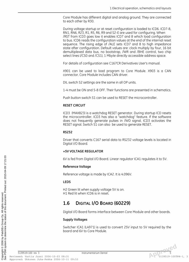
1.5 C167 CORE MODULE (CODE 60244)
OP100/OP100 D is a microprocessor controlled equipment. Core Modulemonitors control it’s all movements and other operations, except the headsupport lock operation and ceph soft tissue display (in OP100). All keyinputs, microswitches and optocouplers are read by the Core Module.Accordingly the Core Module controls all operations by supplying controlsignals through it's input/output. Core Module is connected to otherboards through Digital I/O Board (60229). X902 connects module to DigitalI/O Board.
Fig 1.1. C167 Core Module Block Diagram.
SAB-C167CR-LM (ICD6) is 16-bit microcontroller. Program is stored in 8 Mbit flash ICD1. 5 MHz clock frequency is multiplied internally by four toget operating frequency 20 MHz.
POWER SUPPLY BOARD FUSES
FUSE RATING FUNCTION SIZE
F1 6.3 AT or 10 AT
+12 VAC 6.3 x 32 mm
F2 6.3 AT +34 VAC 6.3 x 32 mm
F3 2 AT +25 V, -25 V
6.3 x 32 mm
d
4 Instrumentarium Dental 5139519-100 rev 3oved: Ukkonen Juha-Pekka 2006-10-11 09:53ewed: Vartia Jussi 2006-10-03 08:31 Approve
5139519-100TPH-1, 3
1 Electrical operation, schematics and layouts
ApprRevi
See
PD
M s
yste
m to
det
erm
ine
the
stat
us o
f thi
s do
cum
ent.
Prin
ted
out:
2015
-04-
09 1
7:21
:03
Cop
yrig
ht ©
200
6 by
Pal
oDE
x G
roup
Oy.
All
right
s re
serv
ed.
Core Module has different digital and analog ground. They are connectedto each other by R30.
During voltage startup or at reset configuration is loaded to ICD6. ICD7-8,RN1, RN6, R23, R1, R5, R6, R9 and S2-E are used for configuring. When /RST from ICD3 goes low it enables ICD7 and 8 which load configurationto bus. ICD6 reads the configuration values at the end of the internal resetsequence. The rising edge of /ALE sets ICD7 and 8 to high impedancestate after configuration. Default values are: clock multiply by four, 16 bitdemultiplexed data bus, no bootstrap, /WR and /BHE control, two chipselect lines (/CS0 and /CS1), 1 Mbyte directly accessible address space.
For details of configuration see C167CR Derivatives User's manual.
X901 can be used to load program to Core Module. X903 is a CANconnector. Core Module includes CAN driver.
DIL switch S2 settings are the same in all OP units.
1-4 must be ON and 5-8 OFF. Their functions are presented in schematics.
Push button switch S1 can be used to RESET the microcontroller.
RESET CIRCUIT
ICD3 (MAX823) is a watchdog RESET generator. During startup ICD resetsthe microcontroller. ICD3 has also a "watchdog" feature. If the softwaredoes not frequently generate pulses in /WD signal, ICD3 activates theRESET signal. Switch S1 can also be used to generate RESET.
RS232
Driver that converts C167 serial data to RS232 voltage levels is located inDigital I/O Board.
+5V VOLTAGE REGULATOR
6V is fed from Digital I/O Board. Linear regulator ICA1 regulates it to 5V.
Reference Voltage
Reference voltage is made by ICA2. It is 4.096V.
LEDS
H2 Green lit when supply voltage 5V is on.H1 Red lit when ICD6 is in reset.
1.6 DIGITAL I/O BOARD (60229)
Digital I/O Board forms interface between Core Module and other boards.
Supply Voltages
Switcher ICA1 (L4971) is used to convert 25V input to 5V required by theboard and 6V to Core Module.
d
5139519-100 rev 3 Instrumentarium Dental 5oved: Ukkonen Juha-Pekka 2006-10-11 09:53ewed: Vartia Jussi 2006-10-03 08:31 Approve
5139519-100TPH-1, 3
1 Electrical operation, schematics and layouts
ApprRevi
See
PD
M s
yste
m to
det
erm
ine
the
stat
us o
f thi
s do
cum
ent.
Prin
ted
out:
2015
-04-
09 1
7:21
:03
Cop
yrig
ht ©
200
6 by
Pal
oDE
x G
roup
Oy.
All
right
s re
serv
ed.
Grounding
There are three separate ground levels in the I/O Board. The actual I/Oboard ground level (GND for +5V). The generator ground-level fromFilament Control Board and Inverter Board (from connector X 4, pins 22,23, 25 and 26). Connected to several optoisolators. Signals from ControlPanel are filtered to the ground level which is connected to chassis at theleft hand lower corner of the IO-board to reduce common modeinterference at control panel cable.
Signals with different GND levels are isolated by optoisolators to eliminatenoise and RF interference problems, but connected inside the Tube HeadAssembly and in the Power Supply Board.
PARALLEL INPUTS/OUTPUTS
I/O from I/O drivers to connectors is buffered and protected according touse:
• Relay drives and control panel signals are buffered by ICD34 (2803,Darlington driver).
• Signals to x-ray generator (Filament Drive Board, Inverter Board andTube Head Assembly) and signal AECFRQ are optoisolated by quad-optoisolators.
• Rest of the output signals are driven by line driver HCT245 andprotected by serial resistors.
SWITCHES:
SERVICE JUMPER X90 pins 3 and 4
Service switch is connected to pins 3 and 4 at connector X90. If pushedand keep pressed during reset or voltage startup it brings serviceprograms available.
OPTION JUMPER X11
Jumper X11 is an option switch, normally in "off" position. When switched"on", the OP100 can be demonstrated normally, but the exposure isprevented. This feature can be used eg. in exhibitions.
Figure: X11 in ON position, XRAYS prevented.
X14
Program options in Core Module.
X15
L position, cephalo on left side.
R position, cephalo on right side.
JP1-3
These are used to select RS232 routing. In OP100/OP100 D they must be inA position.
d
6 Instrumentarium Dental 5139519-100 rev 3oved: Ukkonen Juha-Pekka 2006-10-11 09:53ewed: Vartia Jussi 2006-10-03 08:31 Approve
5139519-100TPH-1, 3
1 Electrical operation, schematics and layouts
ApprRevi
See
PD
M s
yste
m to
det
erm
ine
the
stat
us o
f thi
s do
cum
ent.
Prin
ted
out:
2015
-04-
09 1
7:21
:03
Cop
yrig
ht ©
200
6 by
Pal
oDE
x G
roup
Oy.
All
right
s re
serv
ed.
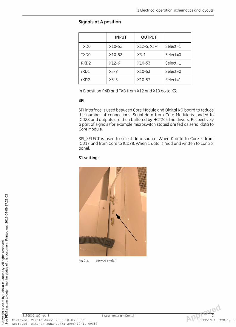
Signals at A position
In B position RXD and TXD from X12 and X10 go to X3.
SPI
SPI interface is used between Core Module and Digital I/O board to reducethe number of connections. Serial data from Core Module is loaded toICD28 and outputs are then buffered by HCT245 line drivers. Respectivelya part of signals (for example microswitch states) are fed as serial data toCore Module.
SPI_SELECT is used to select data source. When 0 data to Core is fromICD17 and from Core to ICD28. When 1 data is read and written to controlpanel.
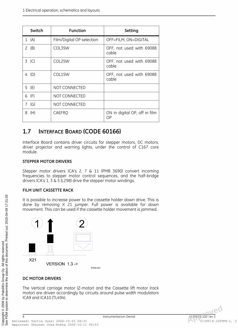
S1 settings
Fig 1.2. Service switch
INPUT OUTPUT
TXD0 X10-52 X12-5, X3-4 Select=1
TXD0 X10-52 X3-1 Select=0
RXD2 X12-6 X10-53 Select=1
rXD1 X3-2 X10-53 Select=0
rXD2 X3-5 X10-53 Select=1
d
5139519-100 rev 3 Instrumentarium Dental 7oved: Ukkonen Juha-Pekka 2006-10-11 09:53ewed: Vartia Jussi 2006-10-03 08:31 Approve
5139519-100TPH-1, 3
1 Electrical operation, schematics and layouts
ApprRevi
See
PD
M s
yste
m to
det
erm
ine
the
stat
us o
f thi
s do
cum
ent.
Prin
ted
out:
2015
-04-
09 1
7:21
:03
Cop
yrig
ht ©
200
6 by
Pal
oDE
x G
roup
Oy.
All
right
s re
serv
ed.
1.7 INTERFACE BOARD (CODE 60166)
Interface Board contains driver circuits for stepper motors, DC motors,driver projector and warning lights, under the control of C167 coremodule.
STEPPER MOTOR DRIVERS
Stepper motor drivers ICA’s 2, 7 & 11 (PMB 3690) convert incomingfrequencies to stepper motor control sequences, and the half-bridgedrivers ICA’s 1, 3 & 5 (L298) drive the stepper motor windings.
FILM UNIT CASSETTE RACK
It is possible to increase power to the cassette holder down drive. This isdone by removing X 21 jumper. Full power is available for downmovement. This can be used if the cassette holder movement is jammed.
DC MOTOR DRIVERS
The Vertical carriage motor (Z-motor) and the Cassette lift motor (rackmotor) are driven accordingly by circuits around pulse width modulatorsICA9 and ICA10 (TL494).
Switch Function Setting
1 (A) Film/Digital OP selection OFF=FILM, ON=DIGITAL
2 (B) COL3SW OFF, not used with 69088cable
3 (C) COL2SW OFF, not used with 69088cable
4 (D) COL1SW OFF, not used with 69088cable
5 (E) NOT CONNECTED
6 (F) NOT CONNECTED
7 (G) NOT CONNECTED
8 (H) CAEFRQ ON in digital OP, off in filmOP
d
8 Instrumentarium Dental 5139519-100 rev 3oved: Ukkonen Juha-Pekka 2006-10-11 09:53ewed: Vartia Jussi 2006-10-03 08:31 Approve
5139519-100TPH-1, 3

1 Electrical operation, schematics and layouts
ApprRevi
See
PD
M s
yste
m to
det
erm
ine
the
stat
us o
f thi
s do
cum
ent.
Prin
ted
out:
2015
-04-
09 1
7:21
:03
Cop
yrig
ht ©
200
6 by
Pal
oDE
x G
roup
Oy.
All
right
s re
serv
ed.
PROJECTORS, WARNING LIGHTS
Positioning projectors are controlled by relay K1. The x-ray warning lightsLA1 and LA2 are controlled by relay K4.
Interface board OT: Laser lights are used in Ortho Trans units. Lasers arecontrolled by transistor T7.
+15V VOLTAGE REGULATOR
+15V operating voltages for PWM circuits ICA9 and ICA10 are regulatedfrom unregulated +25V by ICA1 (LM317).
List of indicators and test points, see Troubleshooting Manual.
1.8 X-RAY GENERATOR
The X-ray generator consist of Tube Head assembly, Filament controlBoard and Inverter Board.
Generator exposure sequence
Time 0: Exposure button pressed, exposure sequence starts
• RG1 on:– Connects high voltage (+310V) to the Inverter Board (via soft start
resistor R6 on Power supply Board).– Red LED H1 (RG1) on Power supply Board is lit.– Green led H1 (+310V) on inverter Board is lit.
• PREH on:– Sets the Filament control Board into preheat mode.– Red LED H7 (PREH) on Filament control Board is lit.
• PREHREL on:– Enables filament power circuit.
d
5139519-100 rev 3 Instrumentarium Dental 9oved: Ukkonen Juha-Pekka 2006-10-11 09:53ewed: Vartia Jussi 2006-10-03 08:31 Approve
5139519-100TPH-1, 3
1 Electrical operation, schematics and layouts
ApprRevi
See
PD
M s
yste
m to
det
erm
ine
the
stat
us o
f thi
s do
cum
ent.
Prin
ted
out:
2015
-04-
09 1
7:21
:03
Cop
yrig
ht ©
200
6 by
Pal
oDE
x G
roup
Oy.
All
right
s re
serv
ed.
– Red LED H6 (PREHREL) on the Filament control Board is lit.– Red LEDs H8, H10 and H11 on the Filament control Board are
glowing.– Connects +25V to the Inverter Board.– Green LED H7 (+25) on the Inverter Board is li
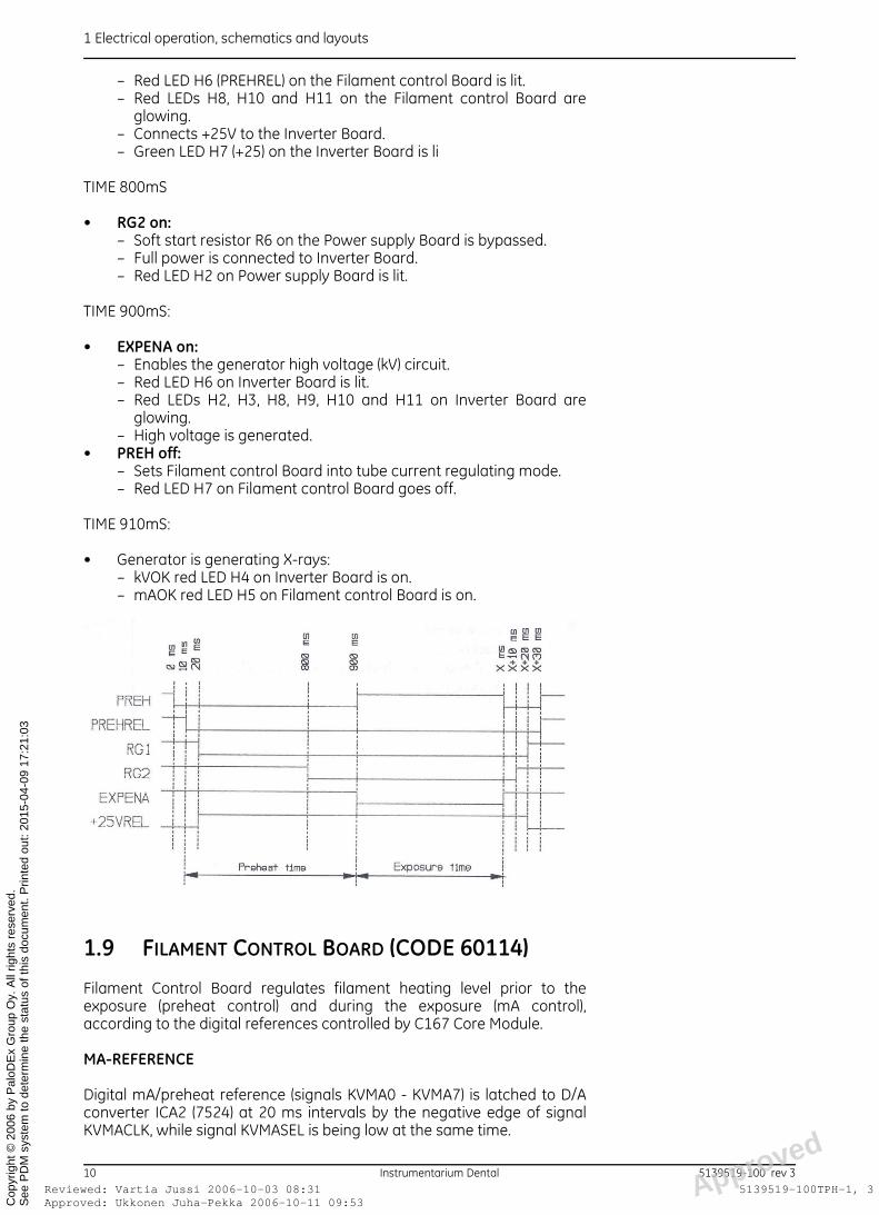
TIME 800mS
• RG2 on:– Soft start resistor R6 on the Power supply Board is bypassed.– Full power is connected to Inverter Board.– Red LED H2 on Power supply Board is lit.
TIME 900mS:
• EXPENA on:– Enables the generator high voltage (kV) circuit.– Red LED H6 on Inverter Board is lit.– Red LEDs H2, H3, H8, H9, H10 and H11 on Inverter Board are
glowing.– High voltage is generated.
• PREH off:– Sets Filament control Board into tube current regulating mode.– Red LED H7 on Filament control Board goes off.
TIME 910mS:
• Generator is generating X-rays:– kVOK red LED H4 on Inverter Board is on.– mAOK red LED H5 on Filament control Board is on.
1.9 FILAMENT CONTROL BOARD (CODE 60114)
Filament Control Board regulates filament heating level prior to theexposure (preheat control) and during the exposure (mA control),according to the digital references controlled by C167 Core Module.
MA-REFERENCE
Digital mA/preheat reference (signals KVMA0 - KVMA7) is latched to D/Aconverter ICA2 (7524) at 20 ms intervals by the negative edge of signalKVMACLK, while signal KVMASEL is being low at the same time.
d
10 Instrumentarium Dental 5139519-100 rev 3oved: Ukkonen Juha-Pekka 2006-10-11 09:53ewed: Vartia Jussi 2006-10-03 08:31 Approve
5139519-100TPH-1, 3

1 Electrical operation, schematics and layouts
ApprRevi
See
PD
M s
yste
m to
det
erm
ine
the
stat
us o
f thi
s do
cum
ent.
Prin
ted
out:
2015
-04-
09 1
7:21
:03
Cop
yrig
ht ©
200
6 by
Pal
oDE
x G
roup
Oy.
All
right
s re
serv
ed.
The +5V input reference from D 17 (LM336-5.0) is fed to the D/A convertervia a buffer amplifier ICA1 (TL074). The output reference (MAREF) is alsobuffered by ICA1.
MA-REGULATOR
PWM (pulse width modulator) ICA3 (TL494) regulates the filament heatinglevel by adjusting the duty cycle of the driver transistors so that thefeedback voltage at pin 1 is the same as the reference voltage at pin 2.
PWM FEEDBACK MULTIPLEXER
The feedback voltage to the pin 1 of the PWM circuit ICA3 (TL494) comesthrough the multiplexer ICD2 (4052). The feedback source (from ICD2)depends on the control signals PREH and PREHREL:
FILAMENT TRANSFORMER DRIVE
Pulse Width Modulator ICA3 (TL494) drives the FET switches T1 and T2,which drive the filament transformer primary. Filament voltage is rectifiedand monitored as signal PREHFB.
MA-FEEDBACK MONITORING
C167 Core Module is able to check some voltage levels in the FilamentControl Board by reading the frequency MAFRQ in different situations; Thevoltage to the U/F converter ICA4 (AD654) comes through the multiplexerICD2 (4052). The voltage source (from ICD2) depends on the control signalsPREH and PREHREL:
STATUS PREH (TP5) PREHEL (TP6) FEEDBACK-SOURCE
preheat sequence normal exposure (mA-reference check)(stand by)
active (0) active (0) passive (15V) passive (15V)
active (0) passive (15V) active (0) passive (15V)
PREHFB MAFB (MAFB) (MAFB)
STATUS PREH (TP5) PREHREL (TP6) VOLTAGE-SOURCE
preheat sequence active (0) active (0) MAFB +5V
normal exposure active (0) passive (15V) MAREF LINEFB
(mA-reference check)
passive (15V) active (0)
(stand by) passive (15V) passive (15V)
d
5139519-100 rev 3 Instrumentarium Dental 11oved: Ukkonen Juha-Pekka 2006-10-11 09:53ewed: Vartia Jussi 2006-10-03 08:31 Approve
5139519-100TPH-1, 3
1 Electrical operation, schematics and layouts
ApprRevi
See
PD
M s
yste
m to
det
erm
ine
the
stat
us o
f thi
s do
cum
ent.
Prin
ted
out:
2015
-04-
09 1
7:21
:03
Cop
yrig
ht ©
200
6 by
Pal
oDE
x G
roup
Oy.
All
right
s re
serv
ed.
The frequency MAFRQ is monitored by the C167 Core Module.
– During preheat sequence C167 Core Module is able to measurethe mA value (tube current), which enables the automatic preheatadjustment.
– During normal exposure the C167 Core Module is able to calibratereading of the U/F converter ICA4 (AD654), since the U/F converterconverts +5V reference into frequency.
– During mA-reference check sequence C167 Core Module is able tocheck the reference that has been written to the D/A converterICA2 (7524).
– During stand-by the C167 Core Module monitors the LINEFB,which indicates the line voltage level.
If MAFB does not rise, signal MAOK does not go active during theexposure.
Measure test points on the board:
TP1= GNDTP2 = mAFBTP4 = mAREF
+/- 15V VOLTAGE REGULATOR
Supply voltages are regulated from unregulated +/- 25V by switchingregulator ICA6 (L4962) for +15V and linear regulator ICA7 (LM337) for -15V.
List of indicators and test points, see Troubleshooting Manual.
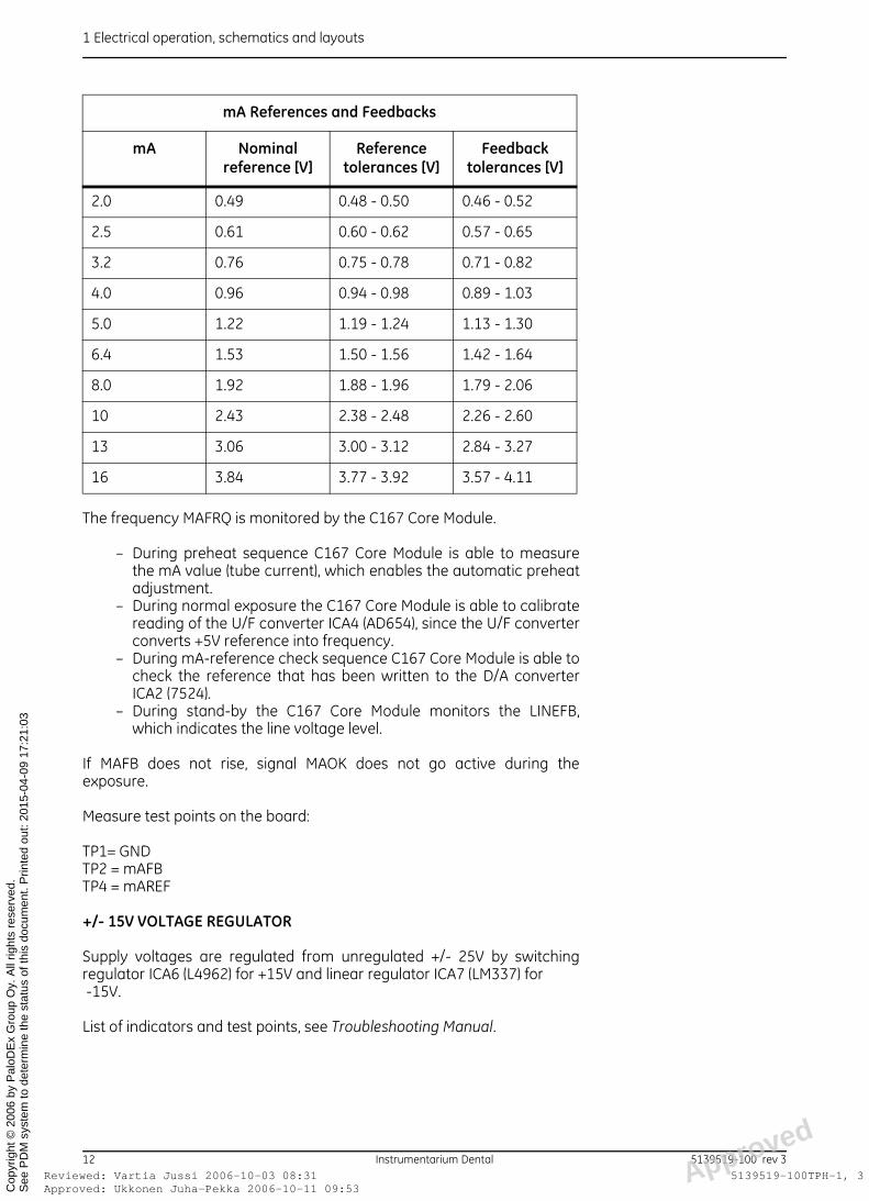
mA References and Feedbacks
mA Nominal reference [V]
Reference tolerances [V]
Feedback tolerances [V]
2.0 0.49 0.48 - 0.50 0.46 - 0.52
2.5 0.61 0.60 - 0.62 0.57 - 0.65
3.2 0.76 0.75 - 0.78 0.71 - 0.82
4.0 0.96 0.94 - 0.98 0.89 - 1.03
5.0 1.22 1.19 - 1.24 1.13 - 1.30
6.4 1.53 1.50 - 1.56 1.42 - 1.64
8.0 1.92 1.88 - 1.96 1.79 - 2.06
10 2.43 2.38 - 2.48 2.26 - 2.60
13 3.06 3.00 - 3.12 2.84 - 3.27
16 3.84 3.77 - 3.92 3.57 - 4.11
d
12 Instrumentarium Dental 5139519-100 rev 3oved: Ukkonen Juha-Pekka 2006-10-11 09:53ewed: Vartia Jussi 2006-10-03 08:31 Approve
5139519-100TPH-1, 3

1 Electrical operation, schematics and layouts
ApprRevi
See
PD
M s
yste
m to
det
erm
ine
the
stat
us o
f thi
s do
cum
ent.
Prin
ted
out:
2015
-04-
09 1
7:21
:03
Cop
yrig
ht ©
200
6 by
Pal
oDE
x G
roup
Oy.
All
right
s re
serv
ed.
NOTE!Rule of thumb: 1V is approx. 4 mA.
1.10 INVERTER BOARD (CODE 60115)
Inverter Board regulates kV during the exposure, according to the digitalreference controlled by C167 Core Module. Inverter Board consists of twomain parts: High voltage section containing the FET bridge, and lowvoltage section containing the regulating, reference and pulsing circuits.
WARNING!Voltages in high voltage part of the inverter board can be deadly. The peak-to-peak voltage level normally exceeds 600 V.
FET BRIDGE (HIGH VOLTAGE)
The FET-transistors in the H-bridge switch power to the high voltagetransformer in the tubehead assembly. The higher the frequency in theFET bridge is, the lower the power level (kV*mA) in the tubehead assembly.In general, FET’s T1, 2, 7 and 8 conduct at the same time, and FET’s 3, 4, 5and 6 accordingly, at the opposite phase.
KV REFERENCE
Digital kV reference (signals KVMA0 - KVMA7) is latched to D/A converterICA3 (7524) at 20 ms intervals by the negative edge of signal KVMACLK,when signal KVMASEL is high at the same time.
The +5V input reference D21 (LM336-5.0) of the D/A converter is bufferedby ICA1 (LM324). The output reference (KVREF) is also buffered by ICA1.
KV REGULATOR
kV regulator consists of KVFB buffer & error amplifier ICA1 (LM324),frequency modulator & comparator ICA2 (LM339) and pulse shapingcircuit & flip flop ICD2 (4013). kV regulator regulates kV by adjusting theoperating frequency of the high voltage FET bridge.
PULSE TRANSFORMER DRIVE
Drivers ICA4 and ICA5 (SG3635) drive the pulse transformers TF3 and TF4,which in turn drive the FET-switches of the H-bridge.
KV-FEEDBACK MONITORING
If kVfb does not rise, signal KVOK does not go active during the exposure.
d
5139519-100 rev 3 Instrumentarium Dental 13oved: Ukkonen Juha-Pekka 2006-10-11 09:53ewed: Vartia Jussi 2006-10-03 08:31 Approve
5139519-100TPH-1, 3
1 Electrical operation, schematics and layouts
ApprRevi
See
PD
M s
yste
m to
det
erm
ine
the
stat
us o
f thi
s do
cum
ent.
Prin
ted
out:
2015
-04-
09 1
7:21
:03
Cop
yrig
ht ©
200
6 by
Pal
oDE
x G
roup
Oy.
All
right
s re
serv
ed.
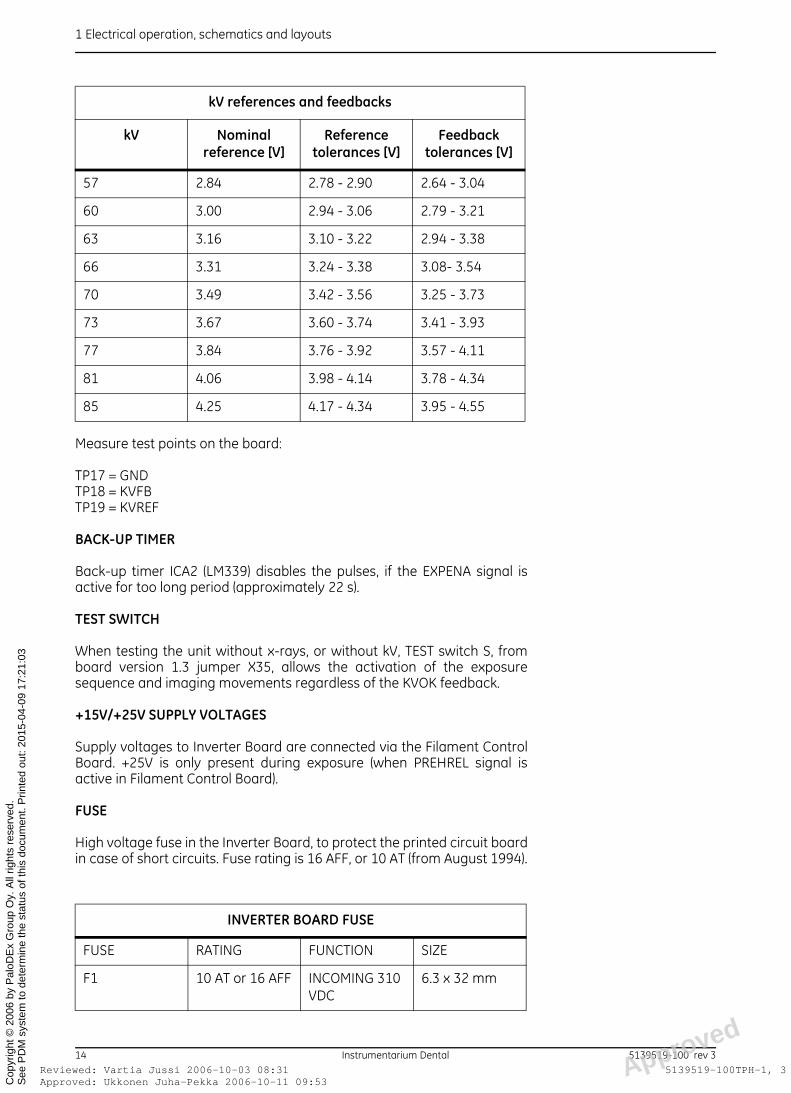
Measure test points on the board:
TP17 = GNDTP18 = KVFBTP19 = KVREF
BACK-UP TIMER
Back-up timer ICA2 (LM339) disables the pulses, if the EXPENA signal isactive for too long period (approximately 22 s).
TEST SWITCH
When testing the unit without x-rays, or without kV, TEST switch S, fromboard version 1.3 jumper X35, allows the activation of the exposuresequence and imaging movements regardless of the KVOK feedback.
+15V/+25V SUPPLY VOLTAGES
Supply voltages to Inverter Board are connected via the Filament ControlBoard. +25V is only present during exposure (when PREHREL signal isactive in Filament Control Board).
FUSE
High voltage fuse in the Inverter Board, to protect the printed circuit boardin case of short circuits. Fuse rating is 16 AFF, or 10 AT (from August 1994).
kV references and feedbacks
kV Nominal reference [V]
Reference tolerances [V]
Feedbacktolerances [V]
57 2.84 2.78 - 2.90 2.64 - 3.04
60 3.00 2.94 - 3.06 2.79 - 3.21
63 3.16 3.10 - 3.22 2.94 - 3.38
66 3.31 3.24 - 3.38 3.08- 3.54
70 3.49 3.42 - 3.56 3.25 - 3.73
73 3.67 3.60 - 3.74 3.41 - 3.93
77 3.84 3.76 - 3.92 3.57 - 4.11
81 4.06 3.98 - 4.14 3.78 - 4.34
85 4.25 4.17 - 4.34 3.95 - 4.55
INVERTER BOARD FUSE
FUSE RATING FUNCTION SIZE
F1 10 AT or 16 AFF INCOMING 310 VDC
6.3 x 32 mm
d
14 Instrumentarium Dental 5139519-100 rev 3oved: Ukkonen Juha-Pekka 2006-10-11 09:53ewed: Vartia Jussi 2006-10-03 08:31 Approve
5139519-100TPH-1, 3
1 Electrical operation, schematics and layouts
ApprRevi
See
PD
M s
yste
m to
det
erm
ine
the
stat
us o
f thi
s do
cum
ent.
Prin
ted
out:
2015
-04-
09 1
7:21
:03
Cop
yrig
ht ©
200
6 by
Pal
oDE
x G
roup
Oy.
All
right
s re
serv
ed.
List of indicators and test points, see Troubleshooting Manual.
NOTE!Rule of thumb: 1V is approx. 20 kV.
1.11 TUBE HEAD ASSEMBLY (CODE 66360)
WARNING!Voltages inside the tube head assembly are deadly. Maintenance of thetube head assembly can only be accomplished at the factory. There areno field serviceable parts inside the tube head assembly, and opening ofthe tube head assembly causes non-repairable damage and oil leakage.
Tube head assembly consists of high voltage transformer TF1, voltagemultiplier circuit D1-16 and C1-8, feedback resistors and the tube insert.
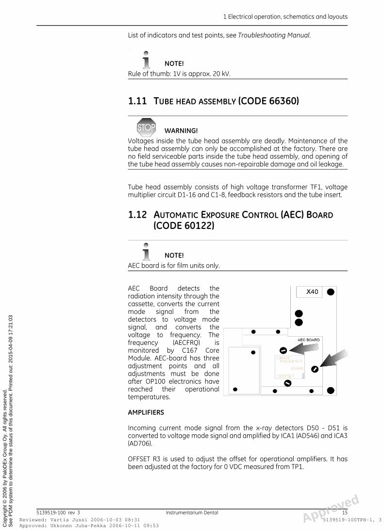
1.12 AUTOMATIC EXPOSURE CONTROL (AEC) BOARD (CODE 60122)
NOTE!AEC board is for film units only.
AEC Board detects theradiation intensity through thecassette, converts the currentmode signal from thedetectors to voltage modesignal, and converts thevoltage to frequency. Thefrequency (AECFRQ) ismonitored by C167 CoreModule. AEC-board has threeadjustment points and alladjustments must be doneafter OP100 electronics havereached their operationaltemperatures.
AMPLIFIERS
Incoming current mode signal from the x-ray detectors D50 - D51 isconverted to voltage mode signal and amplified by ICA1 (AD546) and ICA3(AD706).
OFFSET R3 is used to adjust the offset for operational amplifiers. It hasbeen adjusted at the factory for 0 VDC measured from TP1.
d
5139519-100 rev 3 Instrumentarium Dental 15oved: Ukkonen Juha-Pekka 2006-10-11 09:53ewed: Vartia Jussi 2006-10-03 08:31 Approve
5139519-100TPH-1, 3

1 Electrical operation, schematics and layouts
ApprRevi
See
PD
M s
yste
m to
det
erm
ine
the
stat
us o
f thi
s do
cum
ent.
Prin
ted
out:
2015
-04-
09 1
7:21
:03
Cop
yrig
ht ©
200
6 by
Pal
oDE
x G
roup
Oy.
All
right
s re
serv
ed.
U/F CONVERTER
The amplified voltage is converted to frequency signal by the voltage-to-frequency converter ICA4 (AD654), and the frequency (AECFRQ) is wired tothe C167 Core Module.
BASE FREQUENCY
R27 is used for base frequency adjustment of 5 kHz ± 0.25 kHz at 0 kV / 0 mA. The value is measured from TP2 or by using the “Sr 90 PIn” serviceprogram test mode and reading the frequency from the display.
GAIN
R6 is the gain adjustment. It is adjusted by exposing through a specialservice tool (code 60441). Gain will be adjusted using Sr 90 PIn programAEC mode to read as follows:
230 VAC: 73 kV / 13 mA 144 kHz ± 3 kHz
List of indicators and test points, see Troubleshooting Manual.
1.13 PAN AEC TERMINAL BOARD (CODE 60247)
NOTE!Pan AEC Terminal Board is for digital units only.
Terminal Board and fibre cable
• A bridge between the optical (towards the PC) and electrical (OP)communication
• Sends control messages from the PCI Board to the C167 Core Moduleand Camera according to the address.
• Combines control data (from the OP C167 Core Module and Camera)to the image data from the Camera and sends that to the PC via PCIBoard.
Other features:
• FPGA based logic “router”.• RS422 and RS232 voltage level shifts• LOOP_SENSE: Hot swap feature for camera.• PPOWER, PIMAGE, PDETCLK (from the OP C167 Core Module) control
the image acquisition.• Connections to the OP C167 Core Module and PCI Board are
optoisolated.• 16MHz oscillator and internal 10-multiplier for the Link clock
(160MHz)• See adjustments for PAN AEC gain adjustment
NOTE!Jumper J1 must be open when you use removable cameras. Jumper isonly closed in old units with fixed camera.
d
16 Instrumentarium Dental 5139519-100 rev 3oved: Ukkonen Juha-Pekka 2006-10-11 09:53ewed: Vartia Jussi 2006-10-03 08:31 Approve
5139519-100TPH-1, 3
1 Electrical operation, schematics and layouts
ApprRevi
See
PD
M s
yste
m to
det
erm
ine
the
stat
us o
f thi
s do
cum
ent.
Prin
ted
out:
2015
-04-
09 1
7:21
:03
Cop
yrig
ht ©
200
6 by
Pal
oDE
x G
roup
Oy.
All
right
s re
serv
ed.
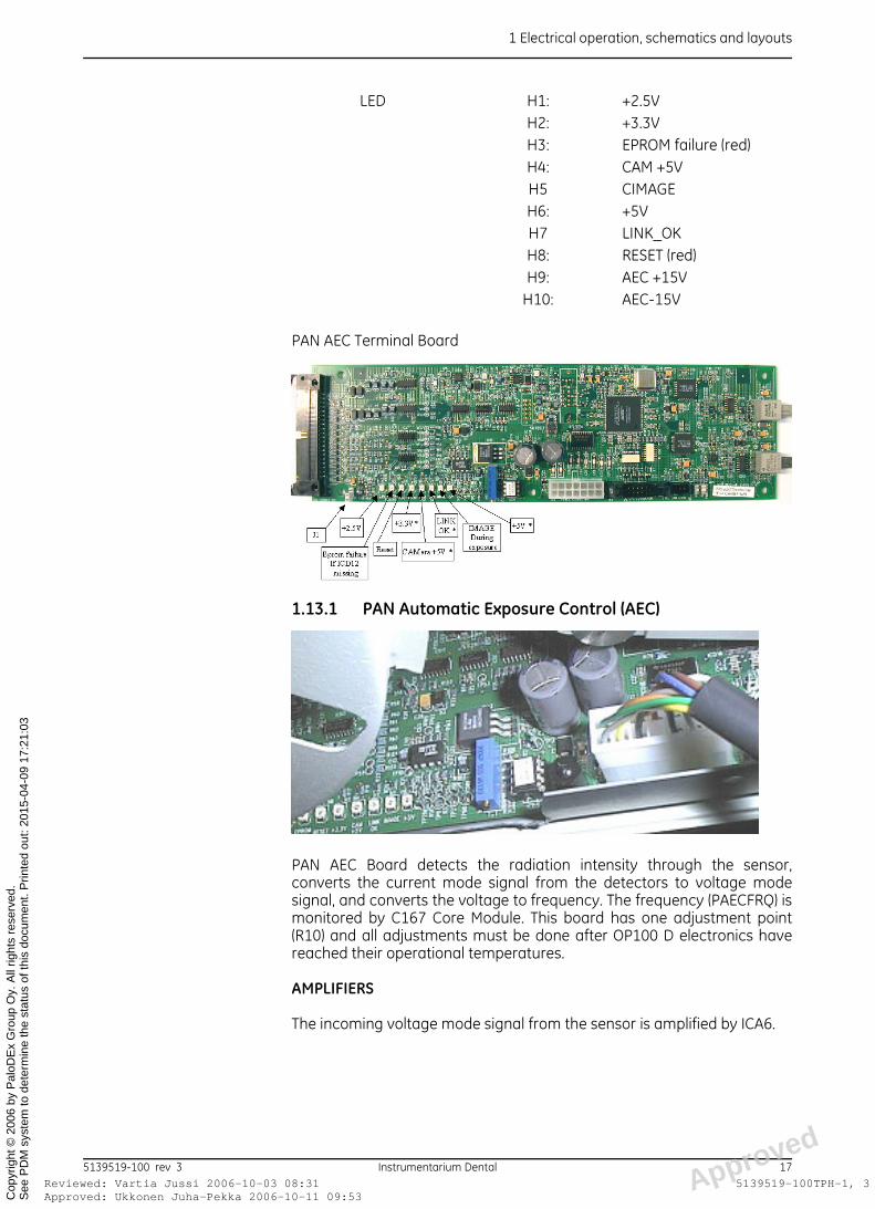
PAN AEC Terminal Board
1.13.1 PAN Automatic Exposure Control (AEC)
PAN AEC Board detects the radiation intensity through the sensor,converts the current mode signal from the detectors to voltage modesignal, and converts the voltage to frequency. The frequency (PAECFRQ) ismonitored by C167 Core Module. This board has one adjustment point(R10) and all adjustments must be done after OP100 D electronics havereached their operational temperatures.
AMPLIFIERS
The incoming voltage mode signal from the sensor is amplified by ICA6.
LED H1: +2.5VH2: +3.3VH3: EPROM failure (red)H4: CAM +5VH5 CIMAGEH6: +5VH7 LINK_OKH8: RESET (red)H9: AEC +15V
H10: AEC-15V
d
5139519-100 rev 3 Instrumentarium Dental 17oved: Ukkonen Juha-Pekka 2006-10-11 09:53ewed: Vartia Jussi 2006-10-03 08:31 Approve
5139519-100TPH-1, 3

1 Electrical operation, schematics and layouts
ApprRevi
See
PD
M s
yste
m to
det
erm
ine
the
stat
us o
f thi
s do
cum
ent.
Prin
ted
out:
2015
-04-
09 1
7:21
:03
Cop
yrig
ht ©
200
6 by
Pal
oDE
x G
roup
Oy.
All
right
s re
serv
ed.
U/F CONVERTER
The amplified voltage is converted to frequency signal by the voltage-to-frequency converter ICA5 and the frequency (PAECFRQ) is wired to theC167 Core Module.
BASE FREQUENCY
Digital unit does not use base frequency. Only during exposure you cansee values of the frequency.
PAN AEC sensitivity adjustment
1 Switch POWER ON and wait 10 minutes for system to warm up.
2 Install to the front cover of the tube head the 20 mmAl phantom
3 Select service program Sr 90 PIn, AEC mode and exposure values 73 kV/13 mA/2 seconds.
4 Make exposures and adjust with the Gain trimmer (R10) on the PANAEC Terminal Board so that the time display shows 144kHz +/-3kHz
NOTE!Before adjusting remember to enable image capturing from CliniView ofsimilar before each AEC frequency test shot.
1.14 PANORAMA & CEPHALOMETRIC CAMERA (DIGI ONLY)
• 2 models: PAN (DCP138 - 7) and CEPH (DCC184 - 8) removablecameras
• Contains CCD Board which includes:– CCDs (2 chips on PAN and 3 on CEPH) with A/D and clocking
electronics– straight fibre optics– scintillator– lead shielding
• Connects to the system via a Terminal Board
d
18 Instrumentarium Dental 5139519-100 rev 3oved: Ukkonen Juha-Pekka 2006-10-11 09:53ewed: Vartia Jussi 2006-10-03 08:31 Approve
5139519-100TPH-1, 3

1 Electrical operation, schematics and layouts
ApprRevi
See
PD
M s
yste
m to
det
erm
ine
the
stat
us o
f thi
s do
cum
ent.
Prin
ted
out:
2015
-04-
09 1
7:21
:03
Cop
yrig
ht ©
200
6 by
Pal
oDE
x G
roup
Oy.
All
right
s re
serv
ed.
Fig 1.3. Functional description of the CCD
PAN / CEPH CAMERA
• CCD terminology (Charged Couple Devices for Quantitative ElectronicImaging):
• Parallel and seriel shifts, Binning, TDI mode (Time Delay Integration)• Correlated Double Sample (CDS), A to D conversion (A/D)• 12-bit image information• Scintillator and fibre optics• Serial communication bus, RS232, 9.6kb/s: Imaging mode selection
and communication.• 6-bit wide image data bus (Hi/Lo bytes, RS422)• Control signal (RS422) to the Camera: TDI clock, line clock controls A/
D conversion according TDI speed.• Control signal (RS232) to the Camera: IMAGE enable• 3 Control signals from the Camera for image data sync • RS-422 signals for byte high/low (H/L) indication, DS for sampling
image data• RS-232 signal (VV) for individual image line.
1.15 CAMERA POWER SUPPLY BOARD (CODE 60197)(DIGI ONLY)
SUPPLIES POWER FOR THE PAN CAMERA
• Generates voltages to the Terminal Board and to the Camera.• +34V, +5V and +3.3V are permanent voltages; the rest are controlled
with POWER signal by the OP C167 Core Module.
LED: H1: +5VH2: -5VH3: +5VH4: -18VH5: +18VH6: +26VH7: +3.3V (permanent)H8: +5V (permanent)H9: +34V (permanent)
d
5139519-100 rev 3 Instrumentarium Dental 19oved: Ukkonen Juha-Pekka 2006-10-11 09:53ewed: Vartia Jussi 2006-10-03 08:31 Approve
5139519-100TPH-1, 3

1 Electrical operation, schematics and layouts
ApprRevi
See
PD
M s
yste
m to
det
erm
ine
the
stat
us o
f thi
s do
cum
ent.
Prin
ted
out:
2015
-04-
09 1
7:21
:03
Cop
yrig
ht ©
200
6 by
Pal
oDE
x G
roup
Oy.
All
right
s re
serv
ed.
1.16 CEPH TERMINAL BOARD (CODE 60191)(DIGI ONLY)
• See PAN AEC terminal Board about the image capturing controlsignals.
• In addition to the image capturing part (excluding AEC) the boardmeasures the nasio support position.
• The measurement result is transmitted to the OP C167 Core Modulewhich ramps down the exposure values accordingly providing softtissue filtering.
• Nasio frequency adjustment
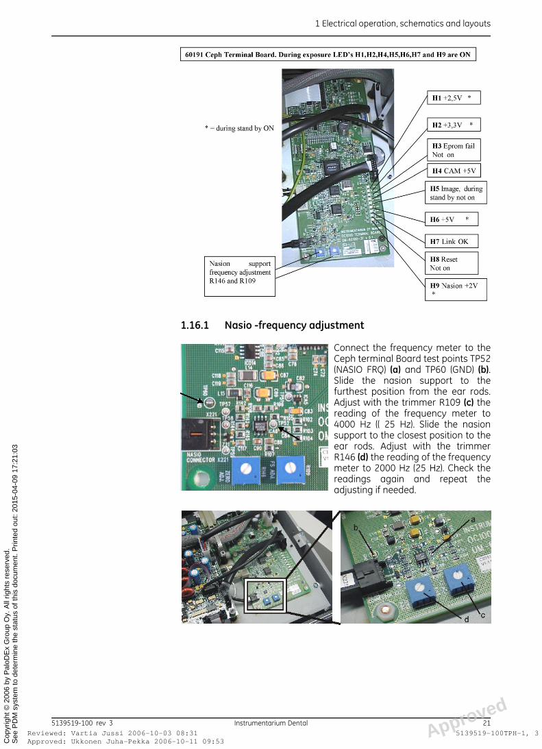
LED H1: +2.5VH2: +3.3VH3: EPROM FAILURE (red)H4: CAM+5VH5: CIMAGEH6: +5VH7: LINK_OKH8: RESET (red)H9: +2V
d
20 Instrumentarium Dental 5139519-100 rev 3oved: Ukkonen Juha-Pekka 2006-10-11 09:53ewed: Vartia Jussi 2006-10-03 08:31 Approve
5139519-100TPH-1, 3
1 Electrical operation, schematics and layouts
ApprRevi
See
PD
M s
yste
m to
det
erm
ine
the
stat
us o
f thi
s do
cum
ent.
Prin
ted
out:
2015
-04-
09 1
7:21
:03
Cop
yrig
ht ©
200
6 by
Pal
oDE
x G
roup
Oy.
All
right
s re
serv
ed.
1.16.1 Nasio -frequency adjustment
Connect the frequency meter to theCeph terminal Board test points TP52(NASIO FRQ) (a) and TP60 (GND) (b).Slide the nasion support to thefurthest position from the ear rods.Adjust with the trimmer R109 (c) thereading of the frequency meter to4000 Hz (( 25 Hz). Slide the nasionsupport to the closest position to theear rods. Adjust with the trimmerR146 (d) the reading of the frequencymeter to 2000 Hz (25 Hz). Check thereadings again and repeat theadjusting if needed.
d
5139519-100 rev 3 Instrumentarium Dental 21oved: Ukkonen Juha-Pekka 2006-10-11 09:53ewed: Vartia Jussi 2006-10-03 08:31 Approve
5139519-100TPH-1, 3
1 Electrical operation, schematics and layouts
ApprRevi
See
PD
M s
yste
m to
det
erm
ine
the
stat
us o
f thi
s do
cum
ent.
Prin
ted
out:
2015
-04-
09 1
7:21
:03
Cop
yrig
ht ©
200
6 by
Pal
oDE
x G
roup
Oy.
All
right
s re
serv
ed.
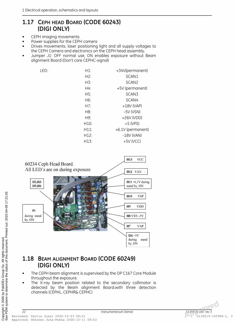
1.17 CEPH HEAD BOARD (CODE 60243)(DIGI ONLY)
• CEPH imaging movements• Power supplies for the CEPH camera• Drives movements, laser positioning light and all supply voltages to
the CEPH Camera and electronics on the CEPH head assembly.• Jumper J1: OFF normal use, ON enables exposure without Beam
alignment Board (Don’t care CEPHC-signal)
1.18 BEAM ALIGNMENT BOARD (CODE 60249)(DIGI ONLY)
• The CEPH beam alignment is supervised by the OP C167 Core Modulethroughout the exposure.
• The X-ray beam position related to the secondary collimator isdetected by the Beam alignment Board.with three detectionchannels (CEPHL, CEPHR& CEPHC)
LED: H1: +34V(permanent)H2: SCAN1H3: SCAN2H4: +5V (permanent)H5: SCAN3H6: SCAN4H7: +18V (VAP)H8: -5V (VSN)H9: +26V (VDD)
H10: +5 (VPS)H11: +6.1V (permanent)H12: -18V (VAN)H13: +5V (VCC)
d
22 Instrumentarium Dental 5139519-100 rev 3oved: Ukkonen Juha-Pekka 2006-10-11 09:53ewed: Vartia Jussi 2006-10-03 08:31 Approve
5139519-100TPH-1, 3

1 Electrical operation, schematics and layouts
ApprRevi
See
PD
M s
yste
m to
det
erm
ine
the
stat
us o
f thi
s do
cum
ent.
Prin
ted
out:
2015
-04-
09 1
7:21
:03
Cop
yrig
ht ©
200
6 by
Pal
oDE
x G
roup
Oy.
All
right
s re
serv
ed.
• If the CEPHL or CEPHR -signals become active the OP C167 CoreModule accelerates or decelerates the rotation and linear (=X-raybeam movement).
• If CEPHC -signal becomes passive the exposure is terminated (Sy32PoA, Alignment error).
• See channel sensitivity adjustment
• Beam alignment detection sensitivity adjustment
1 Check beam alignment (see figure functional description)
2 Align the movements with Sr 91 Cin - T-mode and press exposurebutton.
3 Make (EPS) exposures with Sr 91 Cin M-mode/2 mA and adjust centerchannel (CEPHC) sensitivity (R10) so that it reliably detects (LED H2 islit) radiation. Sensitive increases when R10 is turned clockwise anddecreases when R10 is turned counter-clockwise.
In case of Prüfkörper checks (German units) place 0.8 Cu plate infront of tube and made exposures with 85 kV/8 mA.
4 Move the Ceph movement by hand so that the secondary collimatormoves to the left 10mm and adjust the right channel (CEPHR)sensitivity with R16 and H3. Use 60kV and 2.5mA.
5 Repeat step 4 to the left channel (R4, H1).
NOTE!The function of the LED´s H1, H2 and H3 you can also detect on the controlpanel density scale.
Density Scale
LED H1: CEPHLH2: CEPHCH3: CEPHRH4: +5V
d
5139519-100 rev 3 Instrumentarium Dental 23oved: Ukkonen Juha-Pekka 2006-10-11 09:53ewed: Vartia Jussi 2006-10-03 08:31 Approve
5139519-100TPH-1, 3

1 Electrical operation, schematics and layouts
ApprRevi
See
PD
M s
yste
m to
det
erm
ine
the
stat
us o
f thi
s do
cum
ent.
Prin
ted
out:
2015
-04-
09 1
7:21
:03
Cop
yrig
ht ©
200
6 by
Pal
oDE
x G
roup
Oy.
All
right
s re
serv
ed.
Fig 1.4. Functional description
NOTE!Before adjusting channel sensitivities make sure that x-ray beam is in themiddle of beam alignment board.
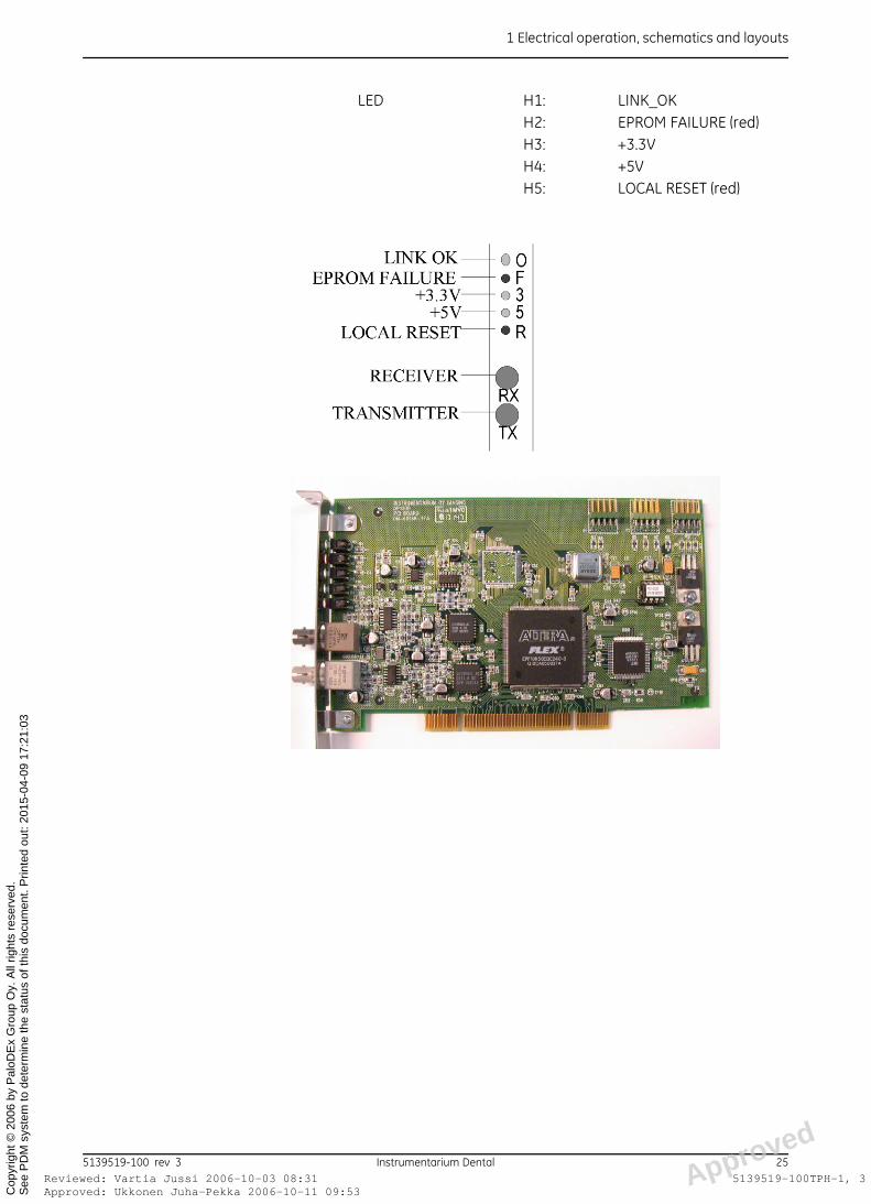
1.19 PCI BOARD (CODE 60187) AND FIBRE CABLE (CODE 69061)(DIGI ONLY)
The standard optical fibre cable length between the PC and OP-unit is10m long, and the data transmission speed is 160Mbps.
Features:
• A bridge between the optical / serial ( from OP) and electrical /parallel PCI bus.
• Sorts incoming image and control data according to the addressattached to the data.
• FPGA based logic “series to parallel converter”• 16MHz oscillator and internal 10-multiplier for the Link clock
(160MHz)
d
24 Instrumentarium Dental 5139519-100 rev 3oved: Ukkonen Juha-Pekka 2006-10-11 09:53ewed: Vartia Jussi 2006-10-03 08:31 Approve
5139519-100TPH-1, 3
1 Electrical operation, schematics and layouts
ApprRevi
See
PD
M s
yste
m to
det
erm
ine
the
stat
us o
f thi
s do
cum
ent.
Prin
ted
out:
2015
-04-
09 1
7:21
:03
Cop
yrig
ht ©
200
6 by
Pal
oDE
x G
roup
Oy.
All
right
s re
serv
ed.
LED H1: LINK_OKH2: EPROM FAILURE (red)H3: +3.3VH4: +5VH5: LOCAL RESET (red)
d
5139519-100 rev 3 Instrumentarium Dental 25oved: Ukkonen Juha-Pekka 2006-10-11 09:53ewed: Vartia Jussi 2006-10-03 08:31 Approve
5139519-100TPH-1, 3
1 Electrical operation, schematics and layouts
ApprRevi
See
PD
M s
yste
m to
det
erm
ine
the
stat
us o
f thi
s do
cum
ent.
Prin
ted
out:
2015
-04-
09 1
7:21
:03
Cop
yrig
ht ©
200
6 by
Pal
oDE
x G
roup
Oy.
All
right
s re
serv
ed.
d
26 Instrumentarium Dental 5139519-100 rev 3oved: Ukkonen Juha-Pekka 2006-10-11 09:53ewed: Vartia Jussi 2006-10-03 08:31 Approve
5139519-100TPH-1, 3
2 Other components
ApprRevi
See
PD
M s
yste
m to
det
erm
ine
the
stat
us o
f thi
s do
cum
ent.
Prin
ted
out:
2015
-04-
09 1
7:21
:03
Cop
yrig
ht ©
200
6 by
Pal
oDE
x G
roup
Oy.
All
right
s re
serv
ed.
2 Other components
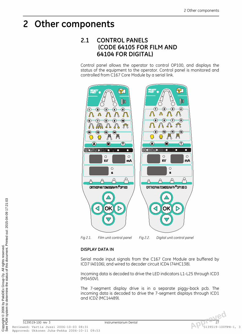
2.1 CONTROL PANELS (CODE 64105 FOR FILM AND 64104 FOR DIGITAL)
Control panel allows the operator to control OP100, and displays thestatus of the equipment to the operator. Control panel is monitored andcontrolled from C167 Core Module by a serial link.
DISPLAY DATA IN
Serial mode input signals from the C167 Core Module are buffered byICD7 (40106), and wired to decoder circuit ICD4 (74HC138).
Incoming data is decoded to drive the LED indicators L1-L25 through ICD3(M5450V).
The 7-segment display drive is in a separate piggy-back pcb. Theincoming data is decoded to drive the 7-segment displays through ICD1and ICD2 (MC14489).
Fig 2.1. Film unit control panel Fig 2.2. Digital unit control panel
d
5139519-100 rev 3 Instrumentarium Dental 27oved: Ukkonen Juha-Pekka 2006-10-11 09:53ewed: Vartia Jussi 2006-10-03 08:31 Approve
5139519-100TPH-1, 3
2 Other components
ApprRevi
See
PD
M s
yste
m to
det
erm
ine
the
stat
us o
f thi
s do
cum
ent.
Prin
ted
out:
2015
-04-
09 1
7:21
:03
Cop
yrig
ht ©
200
6 by
Pal
oDE
x G
roup
Oy.
All
right
s re
serv
ed.
KEY SWITCH DATA OUT
Key switches S1, S2, S3, S4 and S6 (up-left-down-right-OK) are buffered byICD6 (40106), decoded and multiplexed by circuits ICD2 (74HC165) andICD4 (74HC138), and driven to the C167 Core Module through the seriallink.
Exposure switch S5 is wired directly to the C167 Core Module. It is possibleto disable S5 function with Automatic and Manual mode operation. In thiscase the exposure with radiation is acticaed via remote control only. SeeSr 89 rEo or Sr 89 COP options for details.
VOLTAGE REGULATOR
Supply voltage +5V is regulated by ICA5 (L4963).
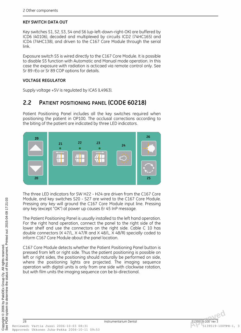
2.2 PATIENT POSITIONING PANEL (CODE 60218)
Patient Positioning Panel includes all the key switches required whenpositioning the patient in OP100. The occlusal corrections according tothe biting of the patient are indicated by three LED indicators.
The three LED indicators for SW H22 - H24 are driven from the C167 CoreModule, and key switches S20 - S27 are wired to the C167 Core Module.Pressing any key will ground the C167 Core Module input line. Pressingany key (except “OK”) at power up causes Er 45 InP message.
The Patient Positioning Panel is usually installed to the left hand operation.For the right hand operation, connect the panel to the right side of thelower shelf and use the connectors on the right side. Cable C 10 hasdouble connectors (X 47/L, X 47/R and X 48/L, X 48/R) specially coded toinform C167 Core Module about the panel location.
C167 Core Module detects whether the Patient Positioning Panel button ispressed from left or right side. Thus the patient positioning is possible onleft or right sides, the positioning should naturally be performed on side,where the positioning lights are projected. The imaging sequenceoperation with digital units is only from one side with clockwise rotation,but with film units the imaging sequence can be bi-directional.
d
28 Instrumentarium Dental 5139519-100 rev 3oved: Ukkonen Juha-Pekka 2006-10-11 09:53ewed: Vartia Jussi 2006-10-03 08:31 Approve
5139519-100TPH-1, 3

2 Other components
ApprRevi
See
PD
M s
yste
m to
det
erm
ine
the
stat
us o
f thi
s do
cum
ent.
Prin
ted
out:
2015
-04-
09 1
7:21
:03
Cop
yrig
ht ©
200
6 by
Pal
oDE
x G
roup
Oy.
All
right
s re
serv
ed.
NOTE!Technically it is possible to have two Patient positioning panels installedon both sides at the same time. In this case, the operation directiondepends on which side the cassette happens to be when starting theimage capture. User program Pr 57 Hon affects to the fact on which sidethe film cassette is automatically raised up.
2.3 HEAD SUPPORT LOCK
Head Support Lock consists of themagnet lock and the lock switchesand the movement is horizontal.The head support assembly isfixed in vertical movement.
+ 25 VDC
Power is received from PowerSupply Board. When the OP100power is on, current is drawnthrough magnet L2 and the headlock is on. Circuit is opened by pressing one of the switches S2 or S3located at the sides of the head support assembly.
NOTE!C167 Core Module does not control the head support lock operation.
2.4 HALOGEN POSITIONING LIGHTS
For panoramic and TMJ positioningthere are three halogen lights. Lightsare controlled through InterfaceBoard. They do not operate in QA norCEPH operating modes.
For digital unit cephalostat patientpositioning there is a laser FH-light.
d
5139519-100 rev 3 Instrumentarium Dental 29oved: Ukkonen Juha-Pekka 2006-10-11 09:53ewed: Vartia Jussi 2006-10-03 08:31 Approve
5139519-100TPH-1, 3

2 Other components
ApprRevi
See
PD
M s
yste
m to
det
erm
ine
the
stat
us o
f thi
s do
cum
ent.
Prin
ted
out:
2015
-04-
09 1
7:21
:03
Cop
yrig
ht ©
200
6 by
Pal
oDE
x G
roup
Oy.
All
right
s re
serv
ed.
2.5 ORTHO TRANS POSITIONING LIGHTS
Ortho Trans models have twolaser lights, one above themirror and the other under therotating cover. Laser lights arecontrolled by Interface boardOT. There are not adjustableparts inside the laser lightassembly. Lasers are lit when
– Ortho Trans opton isactive (Sr 89 COP / 7P11 “on”) and
– the TOMO collimator isselected and lights on or occlusal correction keys are pressed onpositioning panel.
2.6 FH LASER LIGHT (DIGI ONLY)
The laser lightprojector in OC100D is located in the secondary collimator
– If the standard earholders are used the light comes out of theupper hole (1).
– If there are used the extended earholders the light can be movedto the lower hole.
NOTE!Observe pre-drilled marking holes for laser vertical position!
2.7 REMOTE EXPOSURE CONTROL
A remote control exposure switch with cable (code 69961) can beconnected to a junction box located at the rear of the column. This switchis normally open and it is directly wired to the C167 Core Module. Signalsare logical level voltages.
d
30 Instrumentarium Dental 5139519-100 rev 3oved: Ukkonen Juha-Pekka 2006-10-11 09:53ewed: Vartia Jussi 2006-10-03 08:31 Approve
5139519-100TPH-1, 3
2 Other components
ApprRevi
See
PD
M s
yste
m to
det
erm
ine
the
stat
us o
f thi
s do
cum
ent.
Prin
ted
out:
2015
-04-
09 1
7:21
:03
Cop
yrig
ht ©
200
6 by
Pal
oDE
x G
roup
Oy.
All
right
s re
serv
ed.
REMOTE EXPOSURE ONLY
With Sr 89 COP one can configure OP100 so that exposure (Automaticand Manual Exposure control) can only be initiated from the remoteexposure button. However, Test mode can always be demonstrated fromControl Panel while Sr 89 COP / 1 rE is set on.
2.8 CEPH SOFT TISSUE DISPLAY (FILM ONLY)
The movement of the nose support changes the trimmer R 30 resistance.This board will show the nose support travel on two 7 segment displayswith values “0 - 60”, where value represents the distance from the centerof the ear holders to nose support. The actual distance is “value” + “60mm”.
+25 VDC
Power is received from Power Supply board.
ADJUSTMENTS
There are trimmers R6 and R7 to adjust offset for “0” and gain for “60”.
NOTE!This board has no feedback to CPU board
2.9 CEPH SOFT TISSUE AUTOMATIC ADJUSTMENT (DIGI ONLY)
The digital unit automatically adjust the kV/mA values on the soft tissueareas. The reference for the adjustment is coming to the C167 CoreModule through the Nasion support horizontal movement valueaccording to the patients size.
The Nasio frequency can be adjusted from the ceph terminal board(chapter 1.17 in this manual)
2.10 CEPH NOSE SUPPORT
Horizontal and vertical movements. Part of the nose support assembly is atrimmer R221, whose resistance value changes when the nose support ismoved. This value is used as an input to Ceph Soft Tissue automaticadjustment in digital units and as an input for ceph soft tissue display infilm units.
2.11 UP/DOWN PANEL (CODE 60193) + UP/DOWN SWITCH (CODE 60143)(DIGI ONLY)
On the digital cephalostat cover there are a up/down switches for thevertical carriage movement and FH positioning laser light. In film unitinstead of panel there are only up/down switches, signals of both these
d
5139519-100 rev 3 Instrumentarium Dental 31oved: Ukkonen Juha-Pekka 2006-10-11 09:53ewed: Vartia Jussi 2006-10-03 08:31 Approve
5139519-100TPH-1, 3
2 Other components
ApprRevi
See
PD
M s
yste
m to
det
erm
ine
the
stat
us o
f thi
s do
cum
ent.
Prin
ted
out:
2015
-04-
09 1
7:21
:03
Cop
yrig
ht ©
200
6 by
Pal
oDE
x G
roup
Oy.
All
right
s re
serv
ed.
are wired to C167 core module. These keys together with PatientPositioning Panel keys have the same function, but they are wired todifferent I/O ports.
2.12 CEPHALOSTAT L/R CODING
The coding for the cephalostat and x-ray tube orientation is controlledwith the jumper X 15 on the Digital I/O board. CEPH arm side LEFT orRIGHT.
d
32 Instrumentarium Dental 5139519-100 rev 3oved: Ukkonen Juha-Pekka 2006-10-11 09:53ewed: Vartia Jussi 2006-10-03 08:31 Approve
5139519-100TPH-1, 3
3 Overview of Digital Image Capture
ApprRevi
See
PD
M s
yste
m to
det
erm
ine
the
stat
us o
f thi
s do
cum
ent.
Prin
ted
out:
2015
-04-
09 1
7:21
:03
Cop
yrig
ht ©
200
6 by
Pal
oDE
x G
roup
Oy.
All
right
s re
serv
ed.
3 Overview of Digital Image Capture
3.1 OPERATION OVERVIEW• During image acquisition state (when the “TAKE PAN IMAGE” -button
on the CliniView is clicked) the OP C167 Core Module is a master andthe imaging chain a slave:
• OP C167 Core Module starts and ends the exposures if the PC (andthe imaging chain) is ready.
• The PC with the chain acts as a digital cassette, which receives theimage and processes it.
• The PC knows whether any cameras (one or many) are connected tothe system and sends that information to the OP via optical link.Without this information OP will not be READY for exposure.
• The following modalities can be connected to the same optical link(=PCI-board):
1 Panoramic imaging
2 Cephalometric imaging
3 Future option
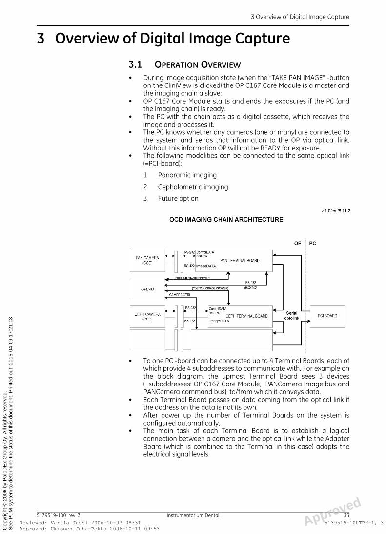
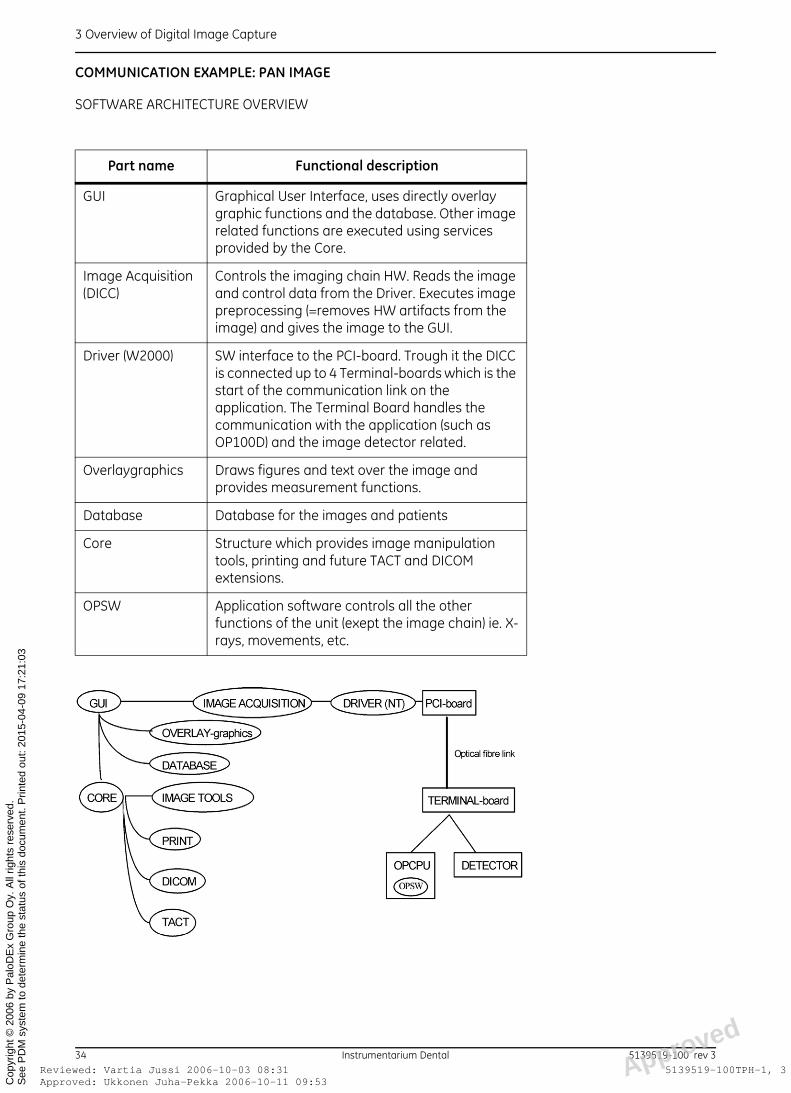
• To one PCI-board can be connected up to 4 Terminal Boards, each ofwhich provide 4 subaddresses to communicate with. For example onthe block diagram, the upmost Terminal Board sees 3 devices(=subaddresses: OP C167 Core Module, PANCamera Image bus andPANCamera command bus), to/from which it conveys data.
• Each Terminal Board passes on data coming from the optical link ifthe address on the data is not its own.
• After power up the number of Terminal Boards on the system isconfigured automatically.
• The main task of each Terminal Board is to establish a logicalconnection between a camera and the optical link while the AdapterBoard (which is combined to the Terminal in this case) adapts theelectrical signal levels.
d
5139519-100 rev 3 Instrumentarium Dental 33oved: Ukkonen Juha-Pekka 2006-10-11 09:53ewed: Vartia Jussi 2006-10-03 08:31 Approve
5139519-100TPH-1, 3
3 Overview of Digital Image Capture
ApprRevi
See
PD
M s
yste
m to
det
erm
ine
the
stat
us o
f thi
s do
cum
ent.
Prin
ted
out:
2015
-04-
09 1
7:21
:03
Cop
yrig
ht ©
200
6 by
Pal
oDE
x G
roup
Oy.
All
right
s re
serv
ed.
COMMUNICATION EXAMPLE: PAN IMAGE
SOFTWARE ARCHITECTURE OVERVIEW
Part name Functional description
GUI Graphical User Interface, uses directly overlay graphic functions and the database. Other image related functions are executed using services provided by the Core.
Image Acquisition (DICC)
Controls the imaging chain HW. Reads the image and control data from the Driver. Executes image preprocessing (=removes HW artifacts from the image) and gives the image to the GUI.
Driver (W2000) SW interface to the PCI-board. Trough it the DICC is connected up to 4 Terminal-boards which is the start of the communication link on the application. The Terminal Board handles the communication with the application (such as OP100D) and the image detector related.
Overlaygraphics Draws figures and text over the image and provides measurement functions.
Database Database for the images and patients
Core Structure which provides image manipulation tools, printing and future TACT and DICOM extensions.
OPSW Application software controls all the other functions of the unit (exept the image chain) ie. X-rays, movements, etc.
d
34 Instrumentarium Dental 5139519-100 rev 3oved: Ukkonen Juha-Pekka 2006-10-11 09:53ewed: Vartia Jussi 2006-10-03 08:31 Approve
5139519-100TPH-1, 3
3 Overview of Digital Image Capture
ApprRevi
See
PD
M s
yste
m to
det
erm
ine
the
stat
us o
f thi
s do
cum
ent.
Prin
ted
out:
2015
-04-
09 1
7:21
:03
Cop
yrig
ht ©
200
6 by
Pal
oDE
x G
roup
Oy.
All
right
s re
serv
ed.
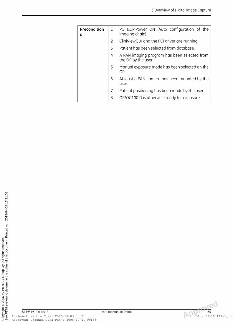
Preconditions
1 PC &OP:Power ON (Auto configuration of theimaging chain)
2 CliniViewGUI and the PCI driver are running
3 Patient has been selected from database.
4 A PAN imaging program has been selected fromthe OP by the user
5 Manual exposure mode has been selected on theOP
6 At least a PAN camera has been mounted by theuser
7 Patient positioning has been made by the user
8 OP/OC100 D is otherwise ready for exposure.
d
5139519-100 rev 3 Instrumentarium Dental 35oved: Ukkonen Juha-Pekka 2006-10-11 09:53ewed: Vartia Jussi 2006-10-03 08:31 Approve
5139519-100TPH-1, 3
3 Overview of Digital Image Capture
ApprRevi
See
PD
M s
yste
m to
det
erm
ine
the
stat
us o
f thi
s do
cum
ent.
Prin
ted
out:
2015
-04-
09 1
7:21
:03
Cop
yrig
ht ©
200
6 by
Pal
oDE
x G
roup
Oy.
All
right
s re
serv
ed.
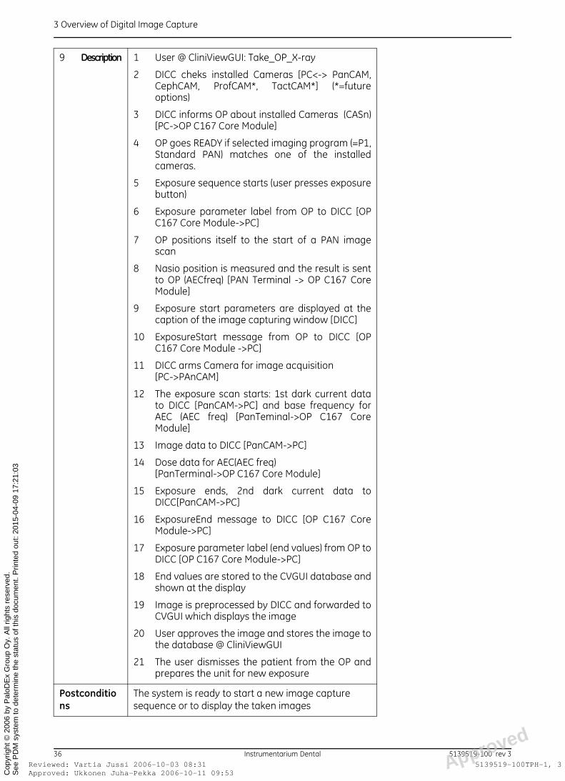
9 Description 1 User @ CliniViewGUI: Take_OP_X-ray
2 DICC cheks installed Cameras [PC<-> PanCAM,CephCAM, ProfCAM*, TactCAM*] (*=futureoptions)
3 DICC informs OP about installed Cameras (CASn)[PC->OP C167 Core Module]
4 OP goes READY if selected imaging program (=P1,Standard PAN) matches one of the installedcameras.
5 Exposure sequence starts (user presses exposurebutton)
6 Exposure parameter label from OP to DICC [OPC167 Core Module->PC]
7 OP positions itself to the start of a PAN imagescan
8 Nasio position is measured and the result is sentto OP (AECfreq) [PAN Terminal -> OP C167 CoreModule]
9 Exposure start parameters are displayed at thecaption of the image capturing window [DICC]
10 ExposureStart message from OP to DICC [OPC167 Core Module ->PC]
11 DICC arms Camera for image acquisition [PC->PAnCAM]
12 The exposure scan starts: 1st dark current datato DICC [PanCAM->PC] and base frequency forAEC (AEC freq) [PanTeminal->OP C167 CoreModule]
13 Image data to DICC [PanCAM->PC]
14 Dose data for AEC(AEC freq)[PanTerminal->OP C167 Core Module]
15 Exposure ends, 2nd dark current data toDICC[PanCAM->PC]
16 ExposureEnd message to DICC [OP C167 CoreModule->PC]
17 Exposure parameter label (end values) from OP toDICC [OP C167 Core Module->PC]
18 End values are stored to the CVGUI database andshown at the display
19 Image is preprocessed by DICC and forwarded toCVGUI which displays the image
20 User approves the image and stores the image tothe database @ CliniViewGUI
21 The user dismisses the patient from the OP andprepares the unit for new exposure
Postconditions
The system is ready to start a new image capture sequence or to display the taken images
d
36 Instrumentarium Dental 5139519-100 rev 3oved: Ukkonen Juha-Pekka 2006-10-11 09:53ewed: Vartia Jussi 2006-10-03 08:31 Approve
5139519-100TPH-1, 3
3 Overview of Digital Image Capture
ApprRevi
See
PD
M s
yste
m to
det
erm
ine
the
stat
us o
f thi
s do
cum
ent.
Prin
ted
out:
2015
-04-
09 1
7:21
:03
Cop
yrig
ht ©
200
6 by
Pal
oDE
x G
roup
Oy.
All
right
s re
serv
ed.
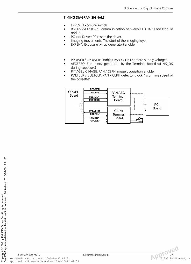
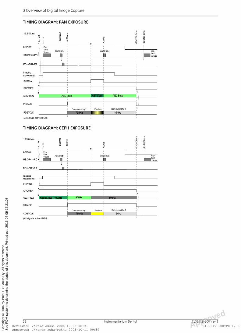
TIMING DIAGRAM SIGNALS
• EXPSW: Exposure switch • RS:OP<=>PC: RS232 communication between OP C167 Core Module
and PC. • PC ==> Driver: PC resets the driver.• Imaging movements: The start of the imaging layer • EXPENA: Exposure (X-ray generator) enable
• PPOWER / CPOWER: Enables PAN / CEPH camera supply voltages• AECFREQ: Frequency generated by the Terminal Board (=LINK_OK
during exposure)• PIMAGE / CIMAGE: PAN / CEPH image acquisition enable• PDETCLK / CDETCLK: PAN / CEPH detector clock; “scanning speed of
the cassette”
d
5139519-100 rev 3 Instrumentarium Dental 37oved: Ukkonen Juha-Pekka 2006-10-11 09:53ewed: Vartia Jussi 2006-10-03 08:31 Approve
5139519-100TPH-1, 3
3 Overview of Digital Image Capture
ApprRevi
See
PD
M s
yste
m to
det
erm
ine
the
stat
us o
f thi
s do
cum
ent.
Prin
ted
out:
2015
-04-
09 1
7:21
:03
Cop
yrig
ht ©
200
6 by
Pal
oDE
x G
roup
Oy.
All
right
s re
serv
ed.
TIMING DIAGRAM: PAN EXPOSURE
TIMING DIAGRAM: CEPH EXPOSURE
d
38 Instrumentarium Dental 5139519-100 rev 3oved: Ukkonen Juha-Pekka 2006-10-11 09:53ewed: Vartia Jussi 2006-10-03 08:31 Approve
5139519-100TPH-1, 3
3 Overview of Digital Image Capture
ApprRevi
See
PD
M s
yste
m to
det
erm
ine
the
stat
us o
f thi
s do
cum
ent.
Prin
ted
out:
2015
-04-
09 1
7:21
:03
Cop
yrig
ht ©
200
6 by
Pal
oDE
x G
roup
Oy.
All
right
s re
serv
ed.
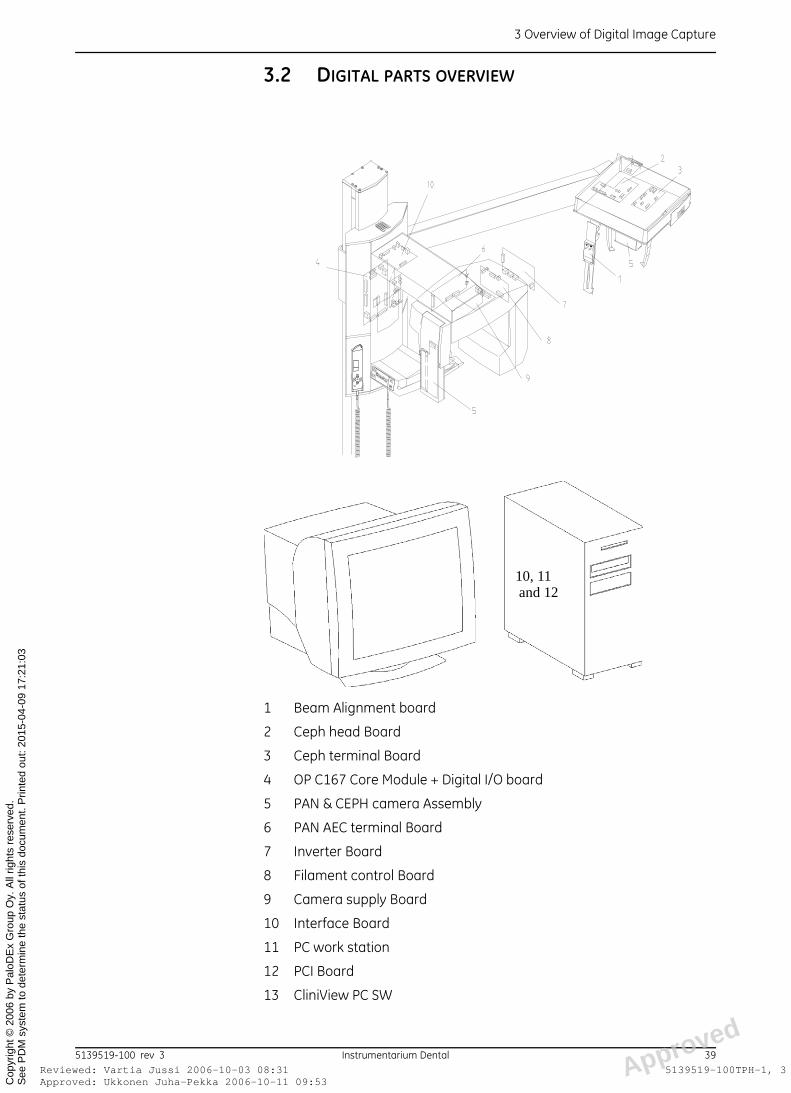
3.2 DIGITAL PARTS OVERVIEW
1 Beam Alignment board
2 Ceph head Board
3 Ceph terminal Board
4 OP C167 Core Module + Digital I/O board
5 PAN & CEPH camera Assembly
6 PAN AEC terminal Board
7 Inverter Board
8 Filament control Board
9 Camera supply Board
10 Interface Board
11 PC work station
12 PCI Board
13 CliniView PC SW
10, 11 and 12
d
5139519-100 rev 3 Instrumentarium Dental 39oved: Ukkonen Juha-Pekka 2006-10-11 09:53ewed: Vartia Jussi 2006-10-03 08:31 Approve
5139519-100TPH-1, 3
3 Overview of Digital Image Capture
ApprRevi
See
PD
M s
yste
m to
det
erm
ine
the
stat
us o
f thi
s do
cum
ent.
Prin
ted
out:
2015
-04-
09 1
7:21
:03
Cop
yrig
ht ©
200
6 by
Pal
oDE
x G
roup
Oy.
All
right
s re
serv
ed.
d
40 Instrumentarium Dental 5139519-100 rev 3oved: Ukkonen Juha-Pekka 2006-10-11 09:53ewed: Vartia Jussi 2006-10-03 08:31 Approve
5139519-100TPH-1, 3
4 List of documents
ApprRevi
See
PD
M s
yste
m to
det
erm
ine
the
stat
us o
f thi
s do
cum
ent.
Prin
ted
out:
2015
-04-
09 1
7:21
:03
Cop
yrig
ht ©
200
6 by
Pal
oDE
x G
roup
Oy.
All
right
s re
serv
ed.
4 List of documents
4.1 COMMON FILM AND DIGITAL UNIT DOCUMENTS
The following OP100 and OP100 D documents should be part of thissection:
In the case of missing or out-of-date documents please contact yourauthorized distributor or Instrumentarium Dental Technical Service.
4.2 FILM UNIT DOCUMENTS
The following OP100 documents should be part of this section:
In the case of missing or out-of-date documents please contact yourauthorized distributor or Instrumentarium Dental Technical Service.
4.3 DIGITAL UNIT DOCUMENTS
The following OP100 D/OC100 D documents should be part of this section:
Code Document69137 Main wiring diagram60229 Digital I/O board60113 Power Supply Board60114 Filament control Board60115 Inverter Board60134 Head support lock60166 Interface Board60218 Patient positioning panel66370 Tube head assembly69088 Cabel C67 (main cable)69091 Ceph straight connector board
Code Document60110 Ceph Soft Tissue Display60122 AEC Board60143 Ceph Up/Down Switch60147 Cassette Opto Sensors64105 Control Panel and Display69136 Ceph cable
Code Document60187 PCI Board 32 bit60191 Ceph terminal Board60193 OCD up/down panel60197 OPD camera supply Board60241 Movement detection Board60243 Ceph head Board
d
5139519-100 rev 3 Instrumentarium Dental 41oved: Ukkonen Juha-Pekka 2006-10-11 09:53ewed: Vartia Jussi 2006-10-03 08:31 Approve
5139519-100TPH-1, 3

4 List of documents
ApprRevi
See
PD
M s
yste
m to
det
erm
ine
the
stat
us o
f thi
s do
cum
ent.
Prin
ted
out:
2015
-04-
09 1
7:21
:03
Cop
yrig
ht ©
200
6 by
Pal
oDE
x G
roup
Oy.
All
right
s re
serv
ed.
In the case of missing or out-of-date documents please contact yourauthorized distributor or Instrumentarium Dental Technical Service.
60247 Pan AEC terminal Board60249 Beam alignment Board69068 Cabel C50 (main cable to ceph)69091 Ceph straight connector board
Code Document
d
42 Instrumentarium Dental 5139519-100 rev 3oved: Ukkonen Juha-Pekka 2006-10-11 09:53ewed: Vartia Jussi 2006-10-03 08:31 Approve
5139519-100TPH-1, 3

Approved: Ukkonen Juha-Pekka 2006-10-11 09:53Reviewed: Vartia Jussi 2006-10-03 08:31 Approved
See
PD
M s
yste
m to
det
erm
ine
the
stat
us o
f thi
s do
cum
ent.
Prin
ted
out:
2015
-04-
09 1
7:21
:03
5139519-100TPH-1, 3
Cop
yrig
ht ©
200
6 by
Pal
oDE
x G
roup
Oy.
All
right
s re
serv
ed.
Orthopantomograph® OP100 & OP100 DOrthoceph® OC100 & OC100 DElectrical Operation & Wiring Manual, English
5139519-100 rev 3 Printed in Finland 09/2006
Instrumentarium Dental reserves the right to make changes in specification and features shown herein, or discontinue the product described at any time without notice or obligation. Contact your Instrumentarium Dental representative for the most current information.
Copyright © 09/2006 by PaloDEx Group Oy. All rights reserved.
Instrumentarium DentalP.O.Box 20, FI-04301 Tuusula, FinlandTel. +358 45 7882 2000Fax +358 45 7882 2506
Americas:Instrumentarium Dental Inc.Milwaukee, Wisconsin, U.S.A.Tel. 800 558 6120Fax 414 481 8665
Approved: Ukkonen Juha-Pekka 2006-10-11 09:53Reviewed: Vartia Jussi 2006-10-03 08:31 Approved
See
PD
M s
yste
m to
det
erm
ine
the
stat
us o
f thi
s do
cum
ent.
Prin
ted
out:
2015
-04-
09 1
7:21
:03
5139519-100TPH-1, 3
Cop
yrig
ht ©
200
6 by
Pal
oDE
x G
roup
Oy.
All
right
s re
serv
ed.