oryone un1 note validator (arm3) oryone un1 m.s. note
TRANSCRIPT

MANUALE ORYONE UN1 CCTALK Pag. 1
Operator’s Manual
Operator’s Manual
Rev. 1.05
ORYONE UN1 note validator (ARM3) ORYONE UN1 M.S. note validator (ARM3)

MANUALE ORYONE UN1 CCTALK Pag. 2
NOTICE
Every possible care has been taken in the preparation of this manual. Nevertheless, there is no guarantee at all times the absolute correspondence of the descriptions contained in this manual, with the characteristics of the product. The Alberici S.p.A. and disclaims any responsibility towards the user with respect to damages, losses, or claims of third parties, arising from use of the product or caused by misinterpretation of this manual. Alberici S.p.A. reserves the right to change, without notice, in any way any portion of this manual.

MANUALE ORYONE UN1
Pag. 3
CONTENTS
1. General............................................................................................................................................................. 4
2. Package contents............................................................................................................................................ 5
3. Product description ......................................................................................................................................... 5
4. Mounting instructions..................................................................................................................................... 7
5. Messages ....................................................................................................................................................... 16
6. Maintenance................................................................................................................................................... 17
7. Calibration...................................................................................................................................................... 18
8. Disposal of the Product ................................................................................................................................. 20
9. Terms of Guarantee ....................................................................................................................................... 20
10. Customer Service .......................................................................................................................................... 20
STORICO REVISIONI
Revisione n° Data Modifica Note
Creazione 14.06.17
v.1.01 03.11.17 MDB su ARM 3
v.1.02 18.12.17 Configurazione parallela in modalità PULSE / Nuova IF ccTalk
v.1.03 14.05.18 Procedura calibrazione
v.1.04 11.03.19 Aggiornamernto mini-USB
v.1.05 24.07.19 Versione con sensore magnetico
MANUALE ORYONE UN1
Pag. 4
1. General
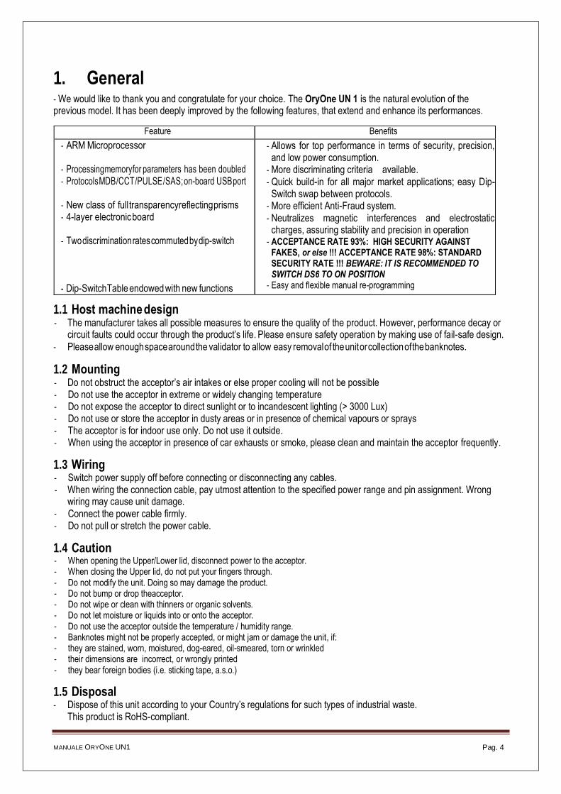
- We would like to thank you and congratulate for your choice. The OryOne UN 1 is the natural evolution of the previous model. It has been deeply improved by the following features, that extend and enhance its performances.
Feature Benefits
- ARM Microprocessor - Processing memory for parameters has been doubled - Protocols MDB / CCT / PULSE / SAS; on-board USB port
- New class of full transparency reflecting prisms - 4-layer electronic board
- Two discrimination rates commuted by dip-switch
- Dip-Switch Table endowed with new functions
- Allows for top performance in terms of security, precision, and low power consumption.
- More discriminating criteria available.
- Quick build-in for all major market applications; easy Dip-Switch swap between protocols.
- More efficient Anti-Fraud system.
- Neutralizes magnetic interferences and electrostatic charges, assuring stability and precision in operation
- ACCEPTANCE RATE 93%: HIGH SECURITY AGAINST FAKES, or else !!! ACCEPTANCE RATE 98%: STANDARD SECURITY RATE !!! BEWARE: IT IS RECOMMENDED TO SWITCH DS6 TO ON POSITION
- Easy and flexible manual re-programming
1.1 Host machine design - The manufacturer takes all possible measures to ensure the quality of the product. However, performance decay or
circuit faults could occur through the product’s life. Please ensure safety operation by making use of fail-safe design.
- Please allow enough space around the validator to allow easy removal of the unit or collection of the banknotes.
1.2 Mounting - Do not obstruct the acceptor’s air intakes or else proper cooling will not be possible - Do not use the acceptor in extreme or widely changing temperature - Do not expose the acceptor to direct sunlight or to incandescent lighting (> 3000 Lux) - Do not use or store the acceptor in dusty areas or in presence of chemical vapours or sprays - The acceptor is for indoor use only. Do not use it outside. - When using the acceptor in presence of car exhausts or smoke, please clean and maintain the acceptor frequently.
1.3 Wiring - Switch power supply off before connecting or disconnecting any cables. - When wiring the connection cable, pay utmost attention to the specified power range and pin assignment. Wrong
wiring may cause unit damage.
- Connect the power cable firmly. - Do not pull or stretch the power cable.
1.4 Caution - When opening the Upper/Lower lid, disconnect power to the acceptor. - When closing the Upper lid, do not put your fingers through. - Do not modify the unit. Doing so may damage the product. - Do not bump or drop theacceptor. - Do not wipe or clean with thinners or organic solvents. - Do not let moisture or liquids into or onto the acceptor. - Do not use the acceptor outside the temperature / humidity range. - Banknotes might not be properly accepted, or might jam or damage the unit, if: - they are stained, worn, moistured, dog-eared, oil-smeared, torn or wrinkled - their dimensions are incorrect, or wrongly printed - they bear foreign bodies (i.e. sticking tape, a.s.o.)
1.5 Disposal - Dispose of this unit according to your Country’s regulations for such types of industrial waste.
This product is RoHS-compliant.

MANUALE ORYONE UN1
Pag. 5
2. Package contents The package contains the following items:
1. ORYONE UN1 note validator 2. Installation manual (this manual), or the Quick Guide
This unit has been carefully packed, with special attention to protect it againt damages. However, if you find anything damaged or missing, please contact immediately your local distributor. Upon reception, please open the box and check for eventual damages, deficiencies or abnormalities, and in such case immediately report it to the forwarder and on the collection receipt.
3. Product description
The labels in the picture show the data updated to the versions of FW and HW valid at 04.06.2019.
Model: ORYONE UN1 Protocols: ccTalk (non-encrypted) + USB port /
Pulse Parallel or Multi-Pulse / MDB) Version HW: 3.00-01 (*) Version FW: u2. 3 A4.0.6 (*) Mechanical Rev. RM: 5.3.0
Power supply: +24V Current draw: 0,4 A (max. 1.0A) Currency: EURO Default currency is EURO: 5.1-10.1-20.1-50.1-100.1 (series Eur I), 5.2-10.2-20.2-50.2-100.2 (series Eur II). Please ask in advance for different needs (see Appendix 1 page 20 for the available datasets). It is however always possible to re-program the validator for a different currency,by using the programming InterFace K-P1C-000009 (or the K-P2C-000003 IF) in combination with the “AlbericiUpgLettore” software.
U: standard 85mm UNIVERSAL banknote inlet R: Vending version (red ilnlet) $: US $ 67mm banknote inlet
MAGNETIC SENSOR VERSION: UMS: standard 85mm UNIVERSAL banknote inlet, RMS: Vending version (red ilnlet) $MS: US $ 67mm banknote inlet These “MS” versions are meant to be used for CURRENCIES WITH MAGNETIC IDENTIFICATION ELEMENTS
The serial number includes the product identifier 'LB0-', followed by the progressive production no. made up of 7 digits. Example: LB0-0084312.
The relevant data of the note validator can also be read by using the “AlbericiUpgLettore” Software:
(*) to-date: 04.06.2019

MANUALE ORYONE UN1
Pag. 6
F. Sled button to pull stacker open
3.1 Parts description
A. Front-plate
D E B. Notes inlet
F
C. Removal button D. Sled button to pull top open (maintenance)
B
E. Dip-switch row
A
G.10p socket
H. SPI Port (stacker connection)
C
H. USB Mini-B port (§)
3.1 Technical Specifications
(§) The USB output is not available on the MDB version.
CAPACITÀ DELL’IMPILATORE / STACKER CAPACITY 300 or 600 banknotes
62 – 82,5 mm larghezza / width - vers. $ M.S. = 67 mm
1,464 Kg
+24V, ±5%

MANUALE ORYONE UN1
Pag. 7
3.2 Dimensions
4. Mounting instructions
4.1 General
Installation Preferably indoors; always integrated into cabinets suited to the place of use.
Positioning Mounting on plate (protected against vibrations and shocks). Allow at least 50 mm free space
around to allow easy removal of the unit or collection of the banknotes.
Please consider that size of 300-banknote stacker is different from size of 600-banknote stacker.
Light Prevent direct sunlight from hitting the inlet: use incandescent lamps in the working environment.
Gradient of incidence of the light: > / = 15 degrees.
8833,,00 // 6677,,00 ((**)) 191,0 – 231,0 (**)
N.B.: All measures in mm
(*) OryOne UN1 - OryOne UN1 Univ. M.S = 83,0 mm OryOne UN1 $ M.S. = 67,0 mm
(**) Stacker 300 banknotes = 191,0 mm Stacker 600 banknotes = 231,0 mm

MANUALE ORYONE UN1
Pag. 8
B
B B B
Support bracket: dimensions (*) show the size of the panel cut-out
4.2 Mechanical fitting
1. Mounting panel can be up to 7 mm thick. Cut out a window as shown in figure below, size 21mm (height) x 95mm (width). Preset the four “A” studs (M4x20) on the mounting panel. Take care to preset also the 3 + 1 studs (M4x20 as well) for the lower fixing holes (“B”).
A A
4 A A
Support bracket: pinpointed dimensions (*) show the size of the panel cut-out
Panel presetting for cut-out and upper 4 studs (M4x20)

MANUALE ORYONE UN1
Pag. 9
1
The chrome bezel cod. AA-0238 is available as option::
2. Press the yellow button “1” (located under the validator) to release the main body from the A-LB0017 support bracket, and slide the validator body backward until it comes out.
3. Fasten the support bracket to the mounting panel by 8 x M4 nuts. Take care not to tighten the nuts too much.
4. Insert the inlet of the note validator in the cut-out, and push the unit frontward, until it hooks in. Make sure that the validator and its bezel are securely fixed to the door.
5. To remove the device from the door/mounting panel, just push upwards button “1”.
NOTICE: Press pushbutton 2 to remove the cash-box from the validator. To open up the cash-box and take banknotes out, slide backward button “3”.
3
2

MANUALE ORYONE UN1
Pag. 10
4.3 Electrical connections and settings of the unit
4.3.1 Connection wiring
Make use of quality components complying with the current draw values, as for example:
Socket IDC socket Socket for flat cable
Wire AWG24 (UL1061) Flat cable, pitch 1,27 mm - AWG28 (UL2651/UL20012)
To connect the validator to the machine board: 1. Make sure the power is off. 2. Insert the cable into the 10p connector. 3. Turn on the power and test for correct operation.
Or else connect the the note reader through the USB Mini-B port. When connected through the USB Mini-B port, the note reader must however be set to work by the ccTalk protocol.
4.3.2 MDB 10p pin-out to 6p plug
When setting the reader for MDB protocol (see 4.3.4 Dip-Switch Settings), the 10p outputs must be converted to the 6p MDB standard cable from the master pcb of the machine.
The MDB cable can be ordered by the # nr. S-031005-000.
OPENING THE HEAD UNIT
Cleaning: wipe the sensor surface off by a lint-free cloth or by a cotton-bud, eventually moisted with
isopropyl alcohol to cl ean parts A, B and C.
C. Rolls B. Rollers A. Sensors Press the yellow button (T) to remove the faceplate.
Cleaning: press the slide-button (P) to open the
upper cover.
Dip-Switch row
P 10p connector
USB Port
P
Power the ORYONE UN1 validator by 24 Vdc.
Once connected, take care that the cable is protected
against any mechanical stress or accidental pull.
MDB ADAPTER
CABLE
A. Optic sensors B. Traction Rollers C. Matching wheels
D. Magnetic Sensor (only in LB-MU02, LB-LU11, LB-MU12)
Starting from Rm 5.2.0, the note validator is equipped with one mini-USB port, that can be used for ccTalk direct communication (without echo message) between the validator and the host. Win10 includes the drivers, else please download them from the validator page in our website. ccTalk communication only flows through the mini-USB port, while power (12/24Vdc for BillyOne, or 24Vdc for OryOne) must be provided to Pin 10 (+) and Pin 8 (GND). The note reader must be set to ccTalk protocol (Dip-Switch 1 = ON). Updating, programming, and calibration still need the external grey USB interface (pendrive or kit) to be connected to the 10p socket.

MANUALE ORYONE UN1
Pag. 11
Pin Signal Function Pin Signal Function
1 CCT CCT Data (active low)
6 NC Not connected
2 NC Not connected 7 Vcc + 24 Vdc (Power supply)
3 NC Not connected 8 Vss GND (Power supply)
4 NC GND 9 NC Not connected
5 NC Not connected 10 Vcc + 24 Vdc (Power supply)
Pin Signal
Total. / Paral. Funzione:
Totaliz. / Parallel
Pin Signal Total. / Paral.
Funzione: Totaliz. / Parallel
1 (!) ENABLE - / PARAL. OUT5
Enable=GND / Parallel 100 €
6 PARAL. OUT1 (active Low) Parallel 5€
2 VOID / (!!) INH +
VOID / Inhibit = +3V÷30V
7 Vdc + 24 Vcc / + 24 Vcc
3 PARAL. OUT3 (active Low) Parallel 20 €
8 GND GND / GND
4 GND GND / GND
9 TOTALIZER / PARAL. OUT2
(active Low) Credit pulse / Paral. 10 €
5 PARAL. OUT4 (active Low) Parallel 50 €
10 Vdc + 24 Vcc / + 24 Vcc
Pin Signal Function Pin Signal Function
1 NC Not connected 6 TX + Tx ( Active low )
2 RX + Rx (+V MDB) 7 Vcc + 24 Vdc (Power supply)
3 RX - Rx (Active low) 8 Vss GND (Power supply) 4 GND GND 9 NC Not connected
5 TX - Tx (0V MDB) 10 Vcc + 24 Vdc (Power supply)
4.3.3 10 Pin interface connector 10p connector
4.3.4 Dip-switch row and unit setting
The Dip-Switches allow to set the communication mode (interface protocol) and other useful features. The
DS row is located on the left side of the validator. ON position is up.
BEWARE! The functions that can be set by Dip-Switch in the OryOne UN1 do not correspond to the ones in the previous OryOne generation.
Examples of communication settings interface by DS5, DS6, DS7
Ex.1: for operation in ccTalk mode, Ex. 2: for operation in Pulse mode, move the dip-switch 1 to ON: 1 € = 1 pulse, 200mA pulse length:
+ 24V
+ 24V
+ 24V
+ 24V
PULSE TOTALIZER: if pin1 = GND ---> validator is enabled. If pin1= floating or +3V÷30V ---> validator is disabled.
PULSE PARALLEL: if pin2 = floating or GND ---> validator is enabled. If pin2 = +3V÷30V ---> validator is disabled.
+ 24V
+ 24V
The 10p connector, for connection to the machine Master board, is located at the right side of the ORYONE UN1 note reader. Starting from hw 2.00 and fw u 2.1.A.3.0.6, the note validator is also equipped with one mini-USB port.

MANUALE ORYONE UN1
Pag. 12
SW N°
DIP-SWITCH FUNCTIONS
SW 1 & SW 2
SW 1 SW 2 Protocol Interface Mode
OFF OFF Pulse
ON OFF ccTalk
OFF ON MDB
ON ON SAS
SW 3
SW 3 Pulse communication modes
OFF Pulse Parallel Outputs (Out 1 = 5€, Out2 = 10€, Out3 = 20€, Out4 = 50€, Out5 = 100€)
ON Pulse Accumulator Output (see SW 4 / SW 5)
SW 4 & SW 5
SW 4 SW 5 Accumulator value (only for Pulse mode)
OFF OFF 5 Euro = 1 Pulse
OFF ON 5 Euro = 5 Pulses (1 Euro = 1 Pulse)
ON OFF 10 Euro = 5 Pulses (5 € disabled)
ON ON 5 Euro = 10 Pulses (1 Euro = 2 Pulses)
SW 6
SW 6 Acceptance rate / Anti-fake Security level
OFF !!!! Acceptance 98% = Standard security level !!!!
ON Acceptance 92% = High security level (false notes mode)
SW 7
SW 7 Pulse length (only for Pulse mode)
OFF 100 msec. / 100 msec. (time ON / time OFF)
ON 200 msec. / 200 msec. (time ON / time OFF) - re-programmable
SW 8
SW 8 Activation of Anti-Fraud signals
OFF Anti-fraud override enabled: first 3 attempts are signaled,+ 2 attempts cause 15’ inactivity, with yellow
flashes (see ** in Table “AF Modes”)
ON Anti-fraud override disabled: the note gets rejected with no fraud attempt signals (see *** in Table “AF
Modes”)
(*) The pulse length can be modified by the dedicated function available in the Alberici Upg programming software menu. Such programming software is available for download in our Website.
Table AF: ANTI-FRAUD OPERATION MODES
(**) Dip-Switch SW8 = OFF:
Progressive attempt no.
Reaction of the Validator
Measure to be taken
Progressive attempt no.
Reaction of the Validator
Measure to betaken
1st Remains in operation
- 4° > error (sequences of 3 red flashes
Switch off and then on
2nd Remains in operation - After the 5th fraud attempt (3 yellow flashes), it is necessary to wait
for automatic restore of service. Take care not to switch 3° the device off.
3rd
> error (sequences of 3 red flashes)
Switch off and then on
(***) Dip-Switch SW8 = ON:
Please pay attention: after any change in the DS settings, power must be turned off and then on again, so that the validator can detect the set operation mode.
Any attempt at “fishing” will cause the note to be rejected, without showing any visible signal.
Error in ccTalk communication. Check voltage level (12 or 24Vdc). Power the device off and on.
Solid yellow light

MANUALE ORYONE UN1
Pag. 13
4.3.5 Enable/Disable programmed denominations
All the notes of the programmed currency are factory enabled. The denominations are stocked in the validator memory. Itis possible todisable/re-enable one (ormore) denomination(s) byfollowing the steps described below:
- Disabling banknotes
Move DS No. 1, DS No. 4 and DS 5 to ON position
Turn power on: the front plate LED will light up white. Insert the banknote that you want to disable. The LED will blink yellow 3 times when the note is returned, to mean that the note has been disabled. Insert the following banknote that you want to inhibit, or switch power off and on again.
- Enabling banknotes
Move DS No. 1 and DS No. 4 to ON position. Turn power on: the front plate LED will light up white. Insert the banknote that you want to enable. The LED will blink green 3 times when the note is returned, to
mean that the note has been enabled. Insert the following
banknote that you want to enable, or switch power off and on again.
When finished, put all the DS in their original position (eg. for operating in ccTalk, all DS must be in OFF position).
NOTICE: enabled and disabled banknotes are signalled at device switch-on, depending on the number of coloured flashes from the faceplate LED.
The LED in the front panel flashes as many times as the total number of the programmed denominations; e.g., for the EURO, it flashes 5 times (1st flash = € 5 banknote, 2nd flash = € 10 note, 3rd flash = € 20 banknote, 4th flash = € 50 banknote, 5th f lash = 100 € banknote). If the LED flashes green, the bill is enabled; if it flashes yellow, the note is disabled.
For example, if the denominations of 5, 10, 50 € are set to be accepted, and the denominations from 20 and 100 € are set to be inhibited, the 1st, 2nd, and 4thflashings will be in green colour, while the 3rd and 5th flashing will be in yellow.

MANUALE ORYONE UN1
Pag. 14
4.3.6 ccTalk Interface circuit
The ORYONE UN1 operates by default with 16 bit CRC Checksum. To convert 16 bit to simple checksum (8bit), please make use of the Alberici Update Software (available on https://www.alberici.it/eng/products/note-validators/without-stacker/oryone).
Open the Options menu and set checksum as follows: 1) OPTIONS: choose and open ADVANCED OPTIONS: choose "Menu Tool: Enable all tools" 2) TOOLS: "Set device parameters" .. . choose either " simple checksum" or "16-bit crc", then press OK.
4.3.7 MDB 10p output
6 Communication Common
5 Master Transmit
4 Master Receive
3 n.c.
2 GND
1 VDC
The MDB version supports all MDB standard commands (level 1).
RXD+
RXD-
x
TXD-
TXD+
+Vin
x
GN

MANUALE ORYONE UN1
Pag. 15
4.3.8 Supported ccTalk headers (16-bit Cyclic Redundancy Check) (Cyclic Redundancy Check)
Supported Command Headers
CcTalk supported commands list
1. Core Commands
Header 192 - Request build code Header 244 - Request product code
Header 245 - Request equipment category id Header 246 - Request manufacturer id Header254 - Simple poll
2. Core Plus Commands
Header 001 - Reset device Header 004 - Request comms revision Header 241 - Request software revision Header 242 - Request serial number
3. Bill Validator Commands
Header 145 - Request currency revision Header 152 - Request bill operating mode Header 153 - Modify bill operating mode Header 154 -Route bill Header 156 - Request country scaling factor Header 157 - Request bill id Header 159 - Read buffered bill events Header 197 – Calculate ROM checksum Header 213 - Request Option flags Header 216 - Request data storage availability Header 227 - Request inhibit status Header 228 - Modify master inhibit status Header 230 - Request inhibit status Header 231 - Modify inhibit status Header 247 - Request variable set
Supported Specifications
CcTalk supported specifications list
1. cctalk Generic Specification Issue 3.2
2. cctalk Expansion for Bill Validators Issue 2.1

MANUALE ORYONE UN1
Pag. 16
5. Messages
5.1 Errors: red and yellow flashing:
The number of red flashes emitted from the front plate allows to check the possible reason for malfunction.
N° of red flashes Description
1 Validator is open
2 Jammed banknote
3 Fraud attempted
5 Adjust optics
7 Stacker full: remove stacked notes or replace by an empty stacker
9 Low power supply 11 Check encoder+motor efficiency
12 Check stacker motor efficiency
14 ROM error
If ccTalk communication drops off, the validator face led will lit up solid yellow:
Solid yellow light Error in ccTalk communication. Check voltage level (12 or 24Vdc). Power the device off and on.
5.2 Blue flashing:
When the stacker has been removed, or if its detector is damaged, the validator front led flashes blue.
5.3 Anti-fraud stop
The banknote reader is equipped with a security device that gets activated in the event of fishing fraud attempts repeated over a period of time. This device can be set through the dip-switch SW2 to operate in a "soft" mode (* DS2 = ON) or in "extended" mode (** DS2 = OFF).
(**) Dip-Switch SW2 OFF
Attempt Validator reaction Do as described below
1° Remains in service -
2° Remains in service -
3° > error (3 red flashes) Reset (switch off then on)
… n° … > error (3 red flashes) Reset (switch off then on)
After the 5th fraud attempt (3 yellow flashes), it is necessary to wait for automatic restore of service. Take care not to switch the device off.
NOTICE: no error status is communicated to the machine, so that the latter does not go out of service, and then continue to maintain the other functions working.
Any attempt at “fishing” will cause the note to be rejected, without showing any visible signal.
(*) Dip-Switch SW2 ON

MANUALE ORYONE UN1
Pag. 17
C
B
A
A
6. Maintenance
6.1 Manual cleaning
The ability of acceptance may decrease due to the accumulation of dust and cellulose dust released by banknotes during transit, or because of residues or sprays, which may spread on the detecting sensors and on transmission parts. It is therefore recommended that you clean these parts monthly, as indicated below.
1. Turn off the power and unplug the cable from the 10-pin connector interface. Press the yellow button C, located under the reader, to release the main body from the faceplate, and slide it backwards.
C
2. Move the D button upward, hold it while sliding the cover backwards; then lift the latter up and rotate it 180° to the right side.
3. Gently wipe the sensors with a clean, lint-free tissue, or with a cotton swab, or with a small sponge, possibly moistened with isopropyl alcohol.
4. Completely remove the dust and residues from the 4 silicone rollers, and from the 4 elastic matching wheels which are located in the lower surface of the upper lid. To remove the most stubborn dirt from rollers and wheels, use isopropyl alcohol.
PAY ATTENTION: do not use organic detergents (ex. alcohol, thinners or petrol). Use only isopropyle alcohol.
A. Optic Sensors B. Traction Rollers
A C. Elastic matching wheels
D D. Magnetic sensor (only in LB-MU02, LB-LU11, LB-MU12)
D

MANUALE ORYONE UN1
Pag. 18
6.2 Jammings
CAUTION! Turn off power before opening its upper lid. Open the top cover by pressing D, as described in section 6.2.1 (point 2), and pull out the stuck banknote (as well as any other objects that will hinder the transit).
7. Calibration
Calibration should be carried out when acceptance rate decreases substantially, and/or after thorough cleaning of the note validator and particularly of its optic sensors glasses.
Full Calibration requires usage of the Alberici Calibration Card (AA-0245). A more basic calibration (Partial Calibration) can be carried out as well without such Card.
Calibration operation is part of the Firmware Update tool ’AlbericiUpgLettore.exe’ (see directions for use “Instructions - ENG - BillyOne, OryOne update”, available on the web site).
Launch the ’AlbericiUpgLettore.exe’ Software, and open its Tools Menu and select ‘Calibration’, then choose ‘Full Calibration’ or ‘Partial Calibration’.
Full Calibration : you will be prompted to use the Calibration card. Place the Card and press OK.
If the ‘Enable advanced functionalities’ box in ‘Options/Advanced’ has been ticked, the program will ask to choose between High Sensibility (factory default) and Low Sensibility. Tick the desired choice, then OK.
Once made your choice, or straight away if the ‘Enable advanced functionalities’ box has not been preset, calibration will start. If the card is not in, the system will remind you to insert it and restart the process:

MANUALE ORYONE UN1
Pag. 19
Once positioned the Calibration Card, press OK button and wait until confirmation of process ended.
Partial Calibration:
If the ‘Enable advanced functionalities’ box has been ticked in the ‘Options/Advanced’, the program will ask to choose between High Sensibility (factory default) and Low Sensibility. Tick the desired choice, then OK.
Once made your choice, or straight away if the ‘Enable advanced functionalities’ box has not been preset, you will be reminded to check that the validator is empty and closed.
Press OK: shortly after, the program will confirm the end of the Partial Calibration:
MANUALE BILLYONE UN1
Pag. 20
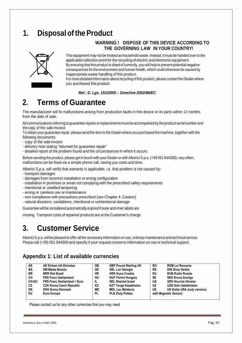
1. Disposal of the Product
WARNING ! DISPOSE OF THIS DEVICE ACCORDING TO
THE GOVERNING LAW IN YOUR COUNTRY!
This equipment may not be treated as household waste. Instead, it must be handed over to the applicable collection point for the recycling of electric and electronic equipment. By ensuring that this product is dised of correctly, you will help to prevent potential negative consequences for the environment and human health, which could otherwise be caused by inappropriate waste handling of this product. For more detailed information about recycling of this product, please contact the Dealer where you purchased this product.
Ref.: D. Lgs. 151/2005 – Directive 2002/96/EC
2. Terms of Guarantee The manufacturer will fix malfunctions arising from production faults in this device or its parts within 12 months from the date of sale.
All communications referring to guarantee repairs or replacements must be accompanied by the product serial number and the copy of the sale invoice. To obtain your guarantee repair, please send the item to the Dealer where you purchased the machine, together with the following documents: - copy of the sale invoice - delivery note stating “returned for guarantee repair” - detailed report of the problem found and the circumstances in which it occurs.
Before sending the product, please get in touch with your Dealer or with Alberici S.p.a. (+39 051 944300); very often, malfunctions can be fixed via a simple phone call, saving you costs and time.
Alberici S.p.a. will verify that warranty is applicable, i.e. that problem is not caused by: - transport damages - damages from incorrect installation or wrong configuration - installation in premises or areas not complying with the prescribed safety requirements - intentional or unwilled tampering - wrong or careless use or maintenance - non-compliance with precautions prescribed (see Chapter 4. Caution) - natural disasters, vandalisms, intentional or unintentional damage
Guarantee will be considered automatically expired if outer and inner labels are
missing. Transport costs of repaired products are at the Customer’s charge.
3. Customer Service Alberici S.p.a. will be pleased to offer all the necessary information on use, ordinary maintenance and technical service. Please call (+39) 051 944300 and specify if your request concerns information on use or technical support.
Appendix 1: List of available currencies
AE AE Dirham UA Emirates BA KM Marka Bosnia BR BRR Rial Brazil
CH FRS Franc Switzerland CH-EU FRS Franc Switzerland + Euro CZ CZK Kruna Czech Republic DK DKK Krona Denmark EU Euro Europa
GB GBP Pound Sterling UK GE GEL Lari Georgia HR HRK Kuna Croatia
HU HUF Florint Hungary IL SKL Sheckel Israel KZ KZT Tenge Kazakhstan MD MDL Leu Moldavia PL PLN Zloty Polska
RO ROM Lei Romania RS DIN Dinar Serbia RU RUB Ruble Russia
SE SKK Krona Sverige UA GRV Hryvnia Ukraine UZ UZB Som Uzbekhistan US US Dollar USA (only versions with Magnetic Sensor)
Please contact us for any other currencies that you may need

MANUALE ORYONE UN1 CCTALK Pag. 21

MANUALE ORYONE UN1 CCTALK Pag. 22

MANUALE ORYONE UN1 CCTALK Pag. 23
Alberici reserves the right to change at any time in any part in the present manual, as well as in the product and in its functions, without previous notice, to the aim of constantly improve the quality of the products.

MANUALE ORYONE UN1 CCTALK Pag. 24
http://www.alberici.net Tel.+39051944300 Fax.+39 051 944 594
Via Ca’ Bianca 421 40024 Castel San Pietro Terme(BO) –ITALY
Progettazione e produzione di sistemi di pagamento, accessori per videogames e macchine vending Design and manufacture of payment systems, accessories for videogames and vending machines