os-pc series infrared temperature sensors os-pc-tsd …os-pc the os-pc is a non-contact temperature...
TRANSCRIPT

OS-PC Series Infrared Temperature Sensors
OS-PC-TSD Touch Screen Interface Module
Operator's Guide

OS-PC
The OS-PC is a non-contact temperature sensor with built-in LED sighting. It has an extremely fast response time, and can measure a spot as small as 1.6 mm in diameter.
The continuous LED sighting illuminates the position and size of the measurement spot while readings are being taken, without affecting the accuracy of the measurement.
The sensor works by detecting the infrared radiation emitted from a surface as a result of its own temperature. The amount of radiation emitted is related to the temperature, and the sensor uses this relationship to provide an accurate temperature measurement.
OS-PC sensors are ideal for measuring the surface temperature of paper, thick plastics, food, rubber, electronic components, cable, ceramics, textiles, painted surfaces and some metals, as well as many other materials.
OS-PC-TSD
The OS-PC-TSD is an optional multilingual touch screen interface module for the OS-PC sensor. It functions as a standalone temperature indicator, alarm unit and configuration tool, and a selectable analogue output allows it to be connected to further instrumentation.
All the settings of the OS-PC sensor are adjustable via the built-in touch screen interface.
When an optional MicroSD Card is inserted into the OS-PC-TSD, the system functions as a fully-configurable temperature data logger.
OS-PC Sensor Specifications
Measurement
Temperature Range 0°C to 500°C
Response time (95% of step change)
-S models: 10 ms to 5 s
-F models: 1 ms to 5 s
Adjustable via averaging function
Target sighting Red LED built-in as standard on all models. Indicates the measured spot size. Switchable on/off.
Measurement Accuracy* -S models: ± 3°C or 1%, whichever is greater
-F models: ± 3.5°C or 1%, whichever is greater
Repeatability* -S models: ± 0.5°C
-F models: ± 1°C
Resolution* -S models: < 0.5°C
-F models: < 1.5°C (0 to 50°C); < 0.7°C (above 50°C)

Measurement (continued)
Emissivity setting Adjustable 0.3 to 1.0 via RS232C or optional touch screen interface
Optics See Field of View Diagrams
* Ambient temp. 23 ± 5°C, emissivity 1.0, averaging time 0.05 s
Electrical
Outputs 1 analogue output and 1 alarm output
Analogue output 4-20 mA (set by default), 0-20 mA, mV/°C or voltage‡, selectable via optional touch screen interface.
Alarm output 1 open drain alarm output, rated 27 V DC, 0.2 A
Supply voltage 5 to 27 V DC, 100 mA max
Digital Communications RS232C Modbus RTU, non-isolated
‡ Voltage can be 0-1, 0-5, or 0-10 V DC, depending on model (see Model Numbers).
Mechanical
Weight (without cable) 85 g
Environmental
Environmental rating IP67
Operating ambient temperature
0°C to 50°C
Storage temperature -15°C to 70°C
Operating ambient humidity 30% to 85% RH non condensing
Display
Display Optional OS-PC-TSD touch screen interface module for indication, configuration, data logging and alarm outputs

Electromagnetic Compatibility Standards
EMC Directive EN61326-1:2013
CISPR 11:2009 Industrial and scientific equipment – Emissions test
IEC61000-4-2 Electrostatic Discharge Immunity
IEC61000-4-3 Electromagnetic Field Immunity
IEC61000-4-4 Burst Immunity
IEC61000-4-5 Surge Immunity
IEC61000-4-6 Conducted RF Immunity
OS-PC-TSD Touch Screen Interface Module Specifications
Interface
Display Format 2.83" (72 mm) resistive touch TFT, 320x240 pixels, backlit
Configurable Parameters Language (English, Chinese, Japanese) Temperature units Displayed temperature (instantaneous, hold) LED sighting on/off Password Date & time (for data logging time stamps) Peak hold period, discharge level Averaging period Correction (gain/offset) Emissivity setting (with teach function) Reflected energy compensation (with teach function) Output type Output temperature range Polarity on error Alarm mode, levels, hysteresis
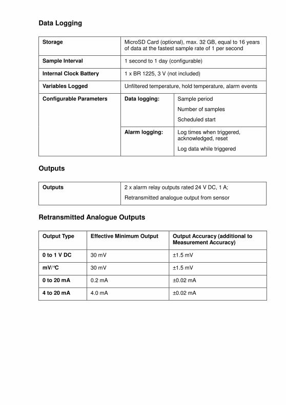
Data Logging
Storage MicroSD Card (optional), max. 32 GB, equal to 16 years of data at the fastest sample rate of 1 per second
Sample Interval 1 second to 1 day (configurable)
Internal Clock Battery 1 x BR 1225, 3 V (not included)
Variables Logged Unfiltered temperature, hold temperature, alarm events
Configurable Parameters
Data logging:
Sample period
Number of samples
Scheduled start
Alarm logging:
Log times when triggered, acknowledged, reset
Log data while triggered
Outputs
Outputs 2 x alarm relay outputs rated 24 V DC, 1 A;
Retransmitted analogue output from sensor
Retransmitted Analogue Outputs
Output Type Effective Minimum Output Output Accuracy (additional to Measurement Accuracy)
0 to 1 V DC 30 mV ±1.5 mV
mV/°C 30 mV ±1.5 mV
0 to 20 mA 0.2 mA ±0.02 mA
4 to 20 mA 4.0 mA ±0.02 mA

Model Numbers
OS-PC Sensor
OS-PC 16 - 2M - 1V
Voltage output option
1V = 0 to 1 V DC 5V = 0 to 5 V DC 10V = 0 to 10 V DC
Note: All models also have 0-20 mA, 4-20 mA, and mV/°C outputs as standard.
Cable length
2M = 2 metres 5M = 5 metres 10M = 10 metres
Field of view and response time
16 = 10 ms response, 1.6 mm spot at 35 mm distance 30 = 10 ms response, 3.0 mm spot at 70 mm distance 55 = 10 ms response, 5.5 mm spot at 120 mm distance
F35 = 1 ms response, 3.5 mm spot at 100 mm distance F70 = 1 ms response, 7.0 mm spot at 200 mm distance
Series
PCU = OS-PC sensor
OS-PC-TSD Touch Screen Interface Module
OS-PC-TSD Touch screen interface module for OS-PC sensor
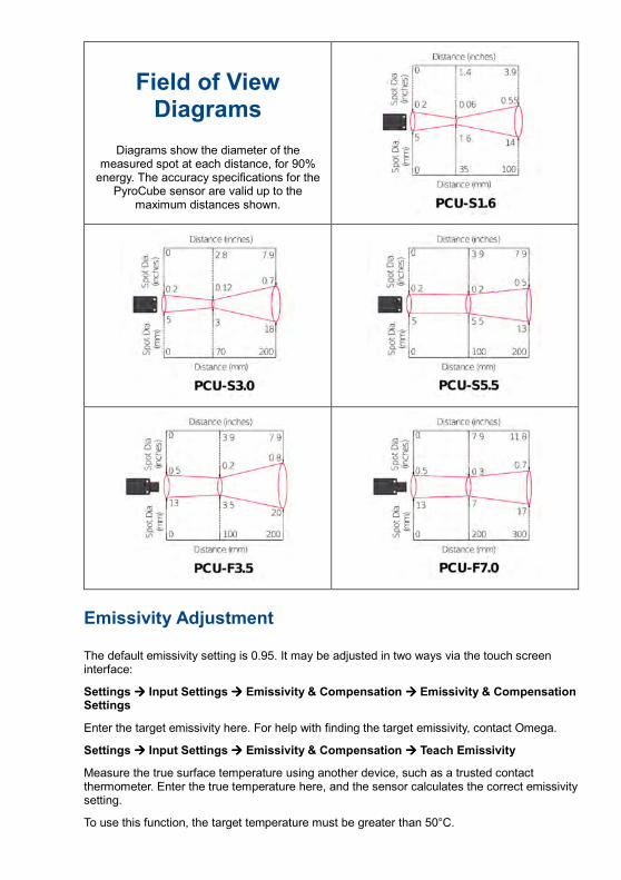
Field of View Diagrams
Diagrams show the diameter of the measured spot at each distance, for 90% energy. The accuracy specifications for the
PyroCube sensor are valid up to the maximum distances shown.
Emissivity Adjustment
The default emissivity setting is 0.95. It may be adjusted in two ways via the touch screen interface:
Settings ���� Input Settings ���� Emissivity & Compensation ���� Emissivity & Compensation Settings
Enter the target emissivity here. For help with finding the target emissivity, contact Omega.
Settings ���� Input Settings ���� Emissivity & Compensation ���� Teach Emissivity
Measure the true surface temperature using another device, such as a trusted contact thermometer. Enter the true temperature here, and the sensor calculates the correct emissivity setting.
To use this function, the target temperature must be greater than 50°C.

Reflected Energy Compensation
Settings ���� Input Settings ���� Emissivity & Compensation ���� Emissivity & Compensation Settings
Some of the infrared energy detected by an infrared temperature sensor is not emitted by the target, but is a reflection of its surroundings.
To ensure an accurate reading, the sensor needs to know the temperature of the source of that reflected energy. In most applications, the surroundings of the target have the same temperature as the sensor itself (e.g. the sensor and target are in the same room). The sensor automatically compensates for the reflected energy, so Reflected Energy Compensation is not required.
However, in some applications, the source of the reflected energy (the surroundings of the target) is much hotter or colder than the sensor itself. In these cases, Reflected Energy Compensation should be enabled.
For example, if the target is inside a furnace and the sensor is outside, the reflected energy is coming from the inner walls of the furnace. Use the Teach Reflected Temperature function to find the correct setting. Enter the true target temperature and the sensor will compensate for the reflected energy.
For assistance, contact Omega.
Alarm Outputs
When used without the optional OS-PC-TSD interface module, the sensor has one open drain alarm output, configurable via RS232C Modbus. The output is rated 27 V DC, 0.2 A.
The OS-PC-TSD has two individually-configurable alarm relay outputs. These are rated 24 V DC, 1 A. These are individually configurable via the touch screen interface.
Each alarm has two set point temperatures (Low and High). The behaviour of the alarm depends on the Alarm Mode.
Alarm Mode Low Measured Temperature High �
Low Set Point High Set Point
High On ALARM ON
High Off ALARM ON
Low On ALARM ON
Low Off ALARM ON
Band On ALARM ON
Band Off ALARM ON ALARM ON
Error On ALARM ON
Error Off
For “Error On” and Error Off” alarms, the alarm monitors for an internal voltage abnormality. In
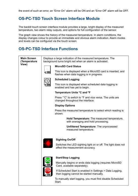
the event of such an error, an “Error On” alarm will be ON and an “Error Off” alarm will be OFF.
OS-PC-TSD Touch Screen Interface Module
The backlit touch screen interface module provides a large, bright display of the measured temperature, two alarm relay outputs, and options for full configuration of the sensor.
The graph view shows the history of the measured temperature. In alarm conditions, the display changes colour to provide an immediate and obvious alarm indication. Alarm modes and levels can be configured via the touch screen.
OS-PC-TSD Interface Functions
Main Screen (Temperature View)
Displays a large indication of the measured temperature. The background turns bright red when an alarm is activated.
MicroSD Card Status
This icon is displayed when a MicroSD card is inserted, and flashes when data logging is in progress.
Scheduled Logging
This icon is displayed when scheduled data logging is enabled and has yet to begin.
Temperature Units °C and °F
Press “°C” to switch to °F and vice versa. The units are changed throughout the interface.
Display Options
Press the measured temperature to select which reading is shown:
Hold Temperature: The measured temperature, with averaging and hold processing.
Unfiltered Temperature: The unprocessed measured temperature.
Sighting On/Off
Switches the LED sighting light on or off. The light does not affect the measurement accuracy.
Start/Stop Logging
Manually begins or ends data logging (requires MicroSD Card, available separately).
If Scheduled Start is enabled in Settings > Data Logging, then logging cannot be started manually.
To manually start logging, you must first disable Scheduled Start.

Acknowledge Alarms
Switches the relay outputs for triggered alarms to their normal, untriggered state. The background of the Temperature View and Graph screen will stay red, and the alarms will not be triggered again until they are reset (see “Alarms” below). Alarms can be acknowledged while the display is locked.
Lock/Unlock
Prevents settings being changed via a four-digit numerical code.
To unlock the sensor, enter the password and press the Unlock icon.
The default password is 1234.
Change Password
Enter, confirm and save a new four-digit code.
Graph
Displays the recent history of the Filtered Temperature and the Sensor Temperature. To scroll backwards and forwards in time, touch the graph and drag it. The graph stores the most recent 24 hours of temperature data.
Reset Graph
Clears and restarts the graph.
Return to Scrolling View
Returns the graph to the real-time scrolling view, showing the most recent measurements.
Settings
Access the configuration parameters. Press Apply to save the settings, or Exit to leave the screen without saving.
Default Settings
Reset all settings to factory defaults.
Settings
Input Settings
These settings affect the sensor and the measured temperature.
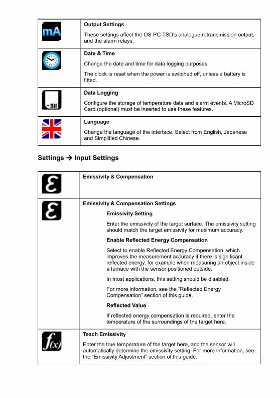
Output Settings
These settings affect the OS-PC-TSD’s analogue retransmission output, and the alarm relays.
Date & Time
Change the date and time for data logging purposes.
The clock is reset when the power is switched off, unless a battery is fitted.
Data Logging
Configure the storage of temperature data and alarm events. A MicroSD Card (optional) must be inserted to use these features.
Language
Change the language of the interface. Select from English, Japanese and Simplified Chinese.
Settings ���� Input Settings
Emissivity & Compensation
Emissivity & Compensation Settings
Emissivity Setting
Enter the emissivity of the target surface. The emissivity setting should match the target emissivity for maximum accuracy.
Enable Reflected Energy Compensation
Select to enable Reflected Energy Compensation, which improves the measurement accuracy if there is significant reflected energy, for example when measuring an object inside a furnace with the sensor positioned outside.
In most applications, this setting should be disabled.
For more information, see the “Reflected Energy Compensation” section of this guide.
Reflected Value
If reflected energy compensation is required, enter the temperature of the surroundings of the target here.
Teach Emissivity
Enter the true temperature of the target here, and the sensor will automatically determine the emissivity setting. For more information, see the “Emissivity Adjustment” section of this guide.

Teach Reflection Value
Enter the true temperature of the target here, and the sensor will automatically compensate for reflected energy. For more information, see the “Reflected Energy Compensation” section of this guide.
Settings ���� Input Settings
Peak Hold
With Peak Hold, the sensor will continue to display or output a peak in the measured temperature for a certain time. This feature is ideal for monitoring the temperature of individual objects on a conveyor, and for ignoring unwanted low readings, such as when a rotating stirring arm in a container of liquid passes the sensor.
Reset
The peak hold mode. Choose from Time or Discharge:
Time
The output returns instantly to the measured temperature after the Reset/Discharge Time.
Discharge
The output decreases steadily after a peak. The rate of decay depends on the Reset/Discharge Time and the Discharge Level.
Reset/Discharge Time
The peak hold period. This depends on the “Reset” setting.
Discharge Level
In “Discharge” mode, this is the percentage of the measured temperature that the peak hold temperature will reach after the
Reset/Discharge Time has elapsed.
Discharge Level has no effect when “Time” mode is enabled.
Peak Hold Off/On
Enable or disable peak hold processing.
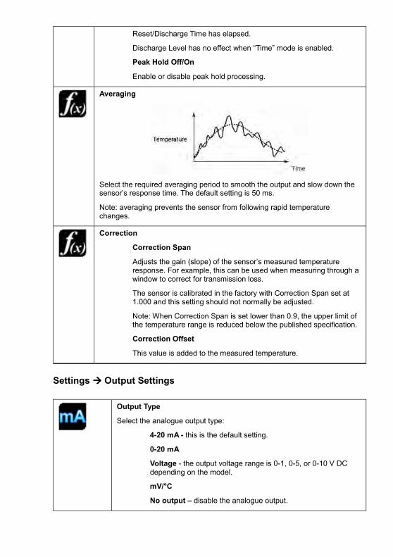
Averaging
Select the required averaging period to smooth the output and slow down the sensor’s response time. The default setting is 50 ms.
Note: averaging prevents the sensor from following rapid temperature changes.
Correction
Correction Span
Adjusts the gain (slope) of the sensor’s measured temperature response. For example, this can be used when measuring through a window to correct for transmission loss.
The sensor is calibrated in the factory with Correction Span set at 1.000 and this setting should not normally be adjusted.
Note: When Correction Span is set lower than 0.9, the upper limit of the temperature range is reduced below the published specification.
Correction Offset
This value is added to the measured temperature.
Settings ���� Output Settings
Output Type
Select the analogue output type:
4-20 mA - this is the default setting.
0-20 mA
Voltage - the output voltage range is 0-1, 0-5, or 0-10 V DC depending on the model.
mV/°C
No output – disable the analogue output.

Output Range
Re-scale the Lower Limit and Upper Limit of the full range of the analogue output. The output is linear between these temperatures.
e.g. 4 mA output at 0°C; 20 mA output at 500°C.
Output Temperature.
Select whether the hold processing settings should be applied to the output temperature.
Unfiltered Temperature
No processing is applied to the output temperature. The raw measured signal is output from the sensor.
Hold Temperature
The peak hold function is applied to the output temperature.
Note: This function is independent from the displayed temperature (see Display Options near the beginning of this table).
Polarity on Error
Determines whether the sensor output will default to the upper or lower limit in a fault condition (internal voltage abnormality).
Untreated
In a fault condition, the sensor will not change output behaviour.
Upper Limit
In a fault condition, the sensor will default to the upper output limit.
Lower Limit
In a fault condition, the sensor will default to the lower output limit.
Settings ���� Output Settings ���� Alarms
Alarms
The settings for the Alarm 1 and Alarm 2 relay outputs are configured individually.
Alarm Mode
High On - The alarm is active above the Alarm High temperature. High Off - The alarm is active below the Alarm High temperature. Low On - The alarm is active below the Alarm Low temperature. Low Off - The alarm is active above the Alarm Low temperature. Band On - The alarm is on between the Alarm Low and High temperatures.

Band Off - The alarm is on below the Alarm Low temperature and above the Alarm High temperature. Error On - The alarm is active in a fault condition (internal voltage error). Error Off - The alarm is active in a normal (non-fault) condition.
For more information, see the section “Alarm Outputs”.
Alarm Settings
Alarm Low
Alarm High
Each alarm has two temperature set points: High and Low. Depending on the Alarm Mode, either one or both of these set points will be used to activate the alarm.
Hysteresis
Example: High On alarm with Hysteresis
Hysteresis is the temperature difference between “alarm on” and “alarm off”. It is a band centred on the alarm setpoint temperature.
The value of Hysteresis is the size of this temperature band.
Settings ���� Data Logging
Data Logging Settings
Sample period
The time, in seconds, between samples.
Number of samples
The number of samples the unit will collect before logging stops. Enter “0” to log data continuously until manually stopped.
Enable Scheduled Start
The sensor begins logging at the Date and Time specified. Logging can also be started and stopped manually.
Date and Time
The date and time for scheduled logging to start.

Alarm Logging Settings
Alarm events can be logged to the MicroSD Card. Alarm log files and settings are independent from Data Logging.
Log Trigger Time
The time that an alarm is triggered will be logged.
Log While Triggered
Data logging will start when an alarm is triggered. 1 sample is logged per second. Logging stops when both alarms are reset.
Log Acknowledge Time
The time that the alarm is acknowledged will be logged.
Log Reset Time
The time that the alarm is reset will be logged.
Data Logging Specifications
The OS-PC and OS-PC-TSD can be used as a standalone data logger. Data logging can be configured via the touch screen interface.
Data is stored on a MicroSD card in .csv format and can be viewed and edited easily using spreadsheet software. The MicroSD card is available as an optional accessory, with an SD Card adapter to transfer data to a PC.
With a 2 GB card, the user can store 28.4 million readings, which is almost 1 year’s worth of data at 1 sample per second. Larger cards provide more storage.
The MicroSD card slot and battery holder are located on the touch screen circuit board in the lid of the OS-PC-TSD. Readings are time and date stamped using the unit’s internal clock. The clock is reset when the power is disconnected, or it will continue if the optional battery is fitted.
Using the OS-PC-TSD as a Data Logger
1. Insert a MicroSD card into the holder on the circuit board inside the lid of the OS-PC-TSD.
2. To retain the date and time when the unit is switched off, fit a battery to the holder on the circuit board inside the lid.
3. Replace the lid and connect the sensor power supply.
4. To set the number of samples to be logged, the time period between samples, and, if
required, to schedule data logging to automatically start, press to access the Settings
menu, then press to access the Data Logging options.

5. To save data logging settings, press
6. To manually start data logging, press on the Temperature View.
7. While logging is in progress, the logging icon flashes on the Temperature View.
8. To stop data logging, press
9. To transfer data to a computer, remove the MicroSD Card from the unit, insert the card into the SD Card adapter (supplied with the MicroSD Card, accessory model MSD) and insert the adapter into an SD Card reader.
Installation of MicroSD Card and Battery
The MicroSD Card and battery slots are located on the touch screen circuit board. Unscrew the lid of the OS-PC-TSD to access them.
The battery is optional. With a battery fitted, the internal clock will continue to run when the power is off. Without a battery, the unit will request the date and time each time the power is cycled.
All other settings are stored in permanent memory and will be preserved when it is switched off, regardless of whether a battery is fitted.
Data Log Files
Data is saved to the MicroSD Card in .csv format. This file format can be opened or imported by spreadsheet software such as Microsoft Excel.
A new folder is created on the MicroSD Card for each day that data is logged.
A new log file is created every time logging is started. The start time is used as the file name.

Sensor Dimensions

OS-PC-TSD Dimensions

Accessories All dimensions in mm
Mounting Bracket
Provides a sturdy mount for the sensor and allows rotation about one axis.
Thickness: 2.0 mm. Weight: 45 g.
Air Purge Collar
Helps prevent dust and condensation from settling on the lens.
Use clean (instrument) air. Maximum flow rate: 5 l/min, maximum pressure 0.2 MPa.
OS-PC-APC (for OS-PC models)

OS-PC-APCF (for OS-PCF models)
Airless Dust Protector
Helps stop dust from reaching the lens. No air supply required. For use in dry atmospheres only.
OS-PC-ADP (for PyroCube S models)
OS-PC-ADPF (for PyroCube F models)
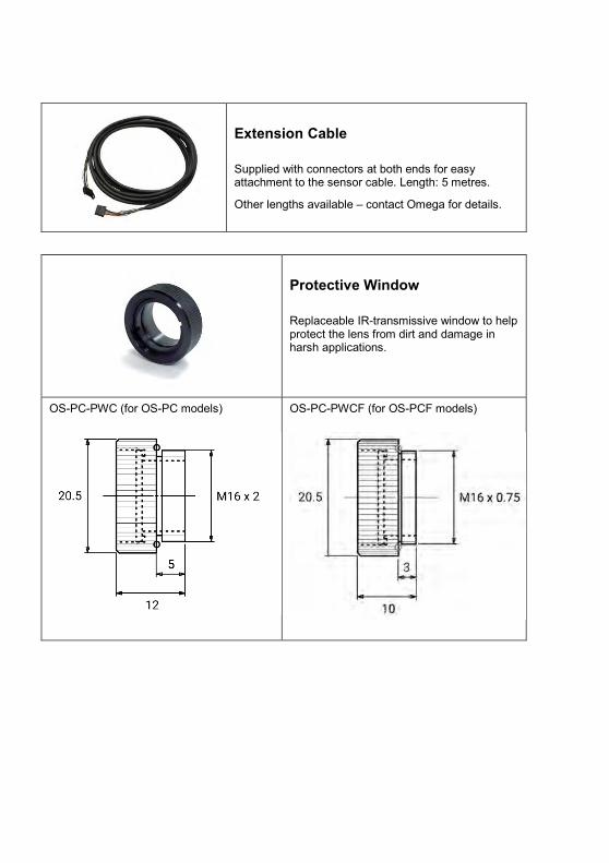
Extension Cable
Supplied with connectors at both ends for easy attachment to the sensor cable. Length: 5 metres.
Other lengths available – contact Omega for details.
Protective Window
Replaceable IR-transmissive window to help protect the lens from dirt and damage in harsh applications.
OS-PC-PWC (for OS-PC models) OS-PC-PWCF (for OS-PCF models)

Right Angled Mirror
Angles the sensor’s field of view by 90°.
A protective window is included to help keep the mirror and lens clean.
OS-PC-RAM (for OS-PC models) and RAMF (for OS-PCF models)
MicroSD Card and Adapter
Stores logged data. SD Card Adapter allows data transfer to a PC.
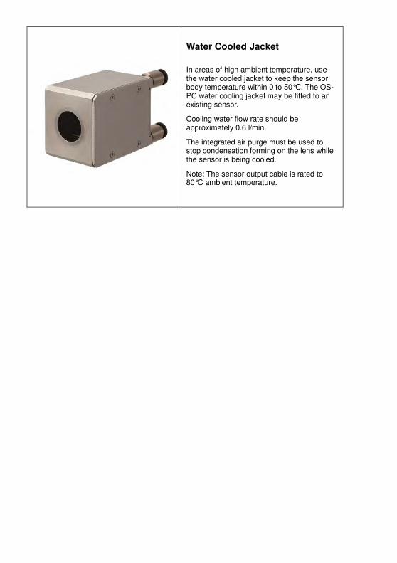
Water Cooled Jacket
In areas of high ambient temperature, use the water cooled jacket to keep the sensor body temperature within 0 to 50°C. The OS-PC water cooling jacket may be fitted to an existing sensor.
Cooling water flow rate should be approximately 0.6 l/min.
The integrated air purge must be used to stop condensation forming on the lens while the sensor is being cooled.
Note: The sensor output cable is rated to 80°C ambient temperature.

Installation
The installation process consists of the following stages:
- Preparation
- Mechanical installation
- Electrical installation
Please read the following sections thoroughly before proceeding with the installation.
Preparation
Distance and Spot Size
The size of the area (spot size) to be measured determines the distance between the sensor and the target. The spot size must not be larger than the target. Choose a suitable mounting distance so that the measured spot size is smaller than the target.
Reflections
The sensor must be installed in a location where energy from tungsten lamps, heaters and sunlight cannot be reflected from the target into the lens. This is especially important for low- temperature targets. Using fluorescent or mercury lamps, or using shields, may help in this respect. For further information and assistance, contact Omega.

Ambient Temperature
The sensing head may be used between 0°C and 50°C ambient temperature. If the ambient temperature is higher than this, consider adding a water cooled jacket.
Avoid thermal shock. Allow 20 minutes for the unit to adjust to large changes in ambient temperature.
Atmospheric Quality
Smoke, fumes, dust or steam can contaminate the lens and cause errors in temperature measurement. Carbon dioxide can also influence the reading.
In these types of environment, the amount of contaminant should be minimised, and the air purge collar should be used to help keep the lens clean.
Electrical Interference
The OS-PC is tested to industrial standards for electromagnetic compatibility (EMC). To minimise electromagnetic interference or ‘noise’, the sensor should be mounted away from motors, generators and such like.
Power Supply
The required supply voltage is 5 to 27 V DC. When using the sensor on its own (without the OS-PC-TSD touch screen terminal) the minimum supply voltage depends on the output. Ensure the power supply is of the correct voltage and is capable of providing an output current of at least 100 mA.
Mechanical Installation
All sensors come with a 2 m, 5 m or 10 m cable as standard (see Model Numbers). The cable may be lengthened using the Extension Cable accessory.
- Affix the sensor to its mounting. The sensor can be mounted on brackets of your own design, or you can use the mounting bracket accessory.
- Switch on the LED sighting to illuminate the measured spot, and adjust the angle of the sensor to aim it.
- Ensure the target is larger than the illuminated spot. If not, adjust the measurement distance for a smaller spot size.
Note: The sensor housing must be connected to earth at one point, either the housing of the sensing head, the electronics module, or the output cable shield termination. To avoid ground loops, please ensure the sensor is grounded at only one of these points.

Electrical Installation
OS-PC (without OS-PC-TSD touch screen module)

Power Supply: Connect the power supply (5 to 27 V DC) to wires 1 (red, +) and 3 (black, Ground)
Analogue Output: Short the inner shield wire 7 (purple) to the ground wire 8 (blue) at the terminal. The analogue output is between wires 6 (green) and 8 (blue).
The minimum sensor power supply voltage depends on the output type being used. Select the output type via RS232C from the following options:
Minimum supply voltage
Minimum Output Output Accuracy
No Analogue Output
5 V - -
4 to 20 mA (default setting)
Depending on loop impedance: 2 V + (0.02 A x loop impedance [Ω] ).
4.0 mA +/- 0.02 mA
0 to 20 mA 0.2 mA +/- 0.02 mA
0 to 1 V 5 V 30 mV +/- 1.5 mV
0 to 5 V 8 V
0 to 10 V 13 V
mV / °C 5 V 30 mV (= 30°C) +/- 1.5 mV
RS232C Output: Connect the RS232 device to wires 2 (yellow, Receive Data), 3 (black, Signal Ground) and 4 (orange, Transmit Data). The signal ground is common with the 0 V rail of the power supply.
LED Sighting or Alarm Output: Wire 5 (white) can be used either as an alarm output, or as a physical switch for the LED sighting.
By default, the function of this wire is set to Alarm Output, and the LED sighting is set to be continuously on.
The function of this wire, the alarm settings, and the on/off state of the LED sighting are all configurable via RS232C Modbus.
- For LED sighting: Connect a switch between wires 5 (white) and 3 (black, Ground).
Note: If wire 5 is shorted with ground then the LED light will turn on, regardless of the LED sighting switch setting.
- For Alarm Output: Connect the input of the alarm monitoring device to wire 5 (white). Connect the 0 V (-) terminal of the alarm monitoring device’s power supply to wire 3 (black, Ground).
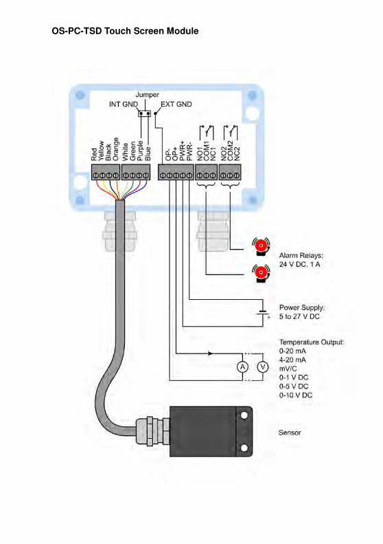
OS-PC-TSD Touch Screen Module

Wiring
The cable is fitted with a male 8-pin Omron e-CON easy-wire connector, and the mating female connector is also supplied. The connectors make it easy to extend the cable and to swap sensors.
You may attach the female connector to your own cable installation, or remove the connectors and wire the sensor into your own terminals directly.
Fitting the Connector
Preparing the Cable
1. Align the cable with the guide marked STRIP GAUGE on the side of the Connector, strip 7 to 8 mm of the cable sheath, and then twist the wires several times.
Connecting the Cable to the Connector
1. Use a flat-blade screw-driver to push down the operating lever inside the operation slot until it locks.
2. Insert the wire fully to the back of the wire insertion hole. Make sure that the cable sheath is inserted into the hole, and that the end of the wire has passed through the contact section.
3. Insert the screwdriver into the release slot, and gently pull back the lever until a click is heard by resetting the lever.

4. Make sure that the following operations have been performed.
- Check that the operating lever is reset
- Check that the procedure in step 2 has been followed. (Pull gently on the cable to make sure that there is resistance, indicating that the connectors are wired correctly.)
Removing the Connector
1. Insert a small flat-bladed screwdriver into the operation slot and press down on the operating lever until it locks.
2. Pull the cable out of the connector.
3. Reset the operating lever by inserting the screwdriver into the release slot and gently pulling back the lever until it clicks.

Modbus over Serial Line (RS232C)
Interface
Baud rate 4800, 9600, 19200, 38400, 57600, 115200 (default 9600)
Data Length 8 bits
Parity None, Odd, Even (default None)
Stop bits 1, 2 (default 2)
Supported Functions
Read register 0x03
Write single register 0x06
The list below includes all available addresses:
R = Read W = Write
Address Description R/W
0x0040 Thermometer firmware version R
0x0100 Measured Temperature - Unfiltered R
0x0101 Status bits 0..3 : Out of Range Indication
0 = Temperature within limits 1 = Temperature > Maximum 2 = Temperature < Minimum
bits 4..7 : Alarm State 0 = No Alarm 1 = Alarm triggered
bits 8..11 : Sample Hold State 0 = No sample hold 1 = Holding sample
bits 12..15 : Peak Hold State 0 = No peak hold 1 = Hold value indicated 2 = Hold value on analogue output 3 = Hold value indicated and on analogue output
R
0x0102 Measured Temperature - Hold Value R
0x0103 Emissivity Setting
50 (0.050) ~ 1000 (1.000)
R
0x0120 Alarm High Setpoint R/W
0x0121 Alarm Low Setpoint R/W
0x0122 Peak Hold ON/OFF R/W

0 = OFF 1 = ON
0x0123 Sample Hold ON/OFF 0 = OFF 1 = ON
R/W
0x0124 Smoothing Time 0 = 0.0001 seconds 1 = 0.0002 seconds 2 = 0.0005 seconds 3 = 0.0010 seconds 4 = 0.0020 seconds 5 = 0.0050 seconds 6 = 0.0100 seconds 7 = 0.0200 seconds 8 = 0.0500 seconds 9 = 0.1000 seconds 10 = 0.2000 seconds 11 = 0.5000 seconds 12 = 1.0000 seconds 13 = 2.0000 seconds 14 = 5.0000 seconds
R/W
0x0125 LED Sight Lamp ON/OFF 0 = OFF 1 = ON
R/W
0x0201 External Pin Function 0 = Alarm 1 = External Sight Lamp Control
R/W
0x0202 Sight Lamp Control 0 = Fixed OFF 1 = ON / OFF 2 = Fixed ON
R/W
0x0208 Ambient Reflection ON/OFF 0 = OFF 1 = ON
R/W
0x0209 Alarm Hysteresis range
0 (0.0) ~ 999 (99.9)
R/W
0x020A Alarm Mode 0 = High ON 1 = High OFF 2 = Low ON 3 = Low OFF 4 = Range ON 5 = Range OFF 6 = Error ON 7 = Error OFF
R/W
0x020C Alarm Temperature 0 = Measured Temperature - Unfiltered 1 = Measured Temperature - Hold Value
R/W
0x020D Peak Hold Reset Type 0 = Time 1 = External 2 = Discharge
R/W
0x020E Peak Hold Reset Time / Discharge Time R/W

1 (0.01 seconds) ~ 1000 (10.00
seconds)
0x020F Peak Hold Discharge Level
20 (0.20) ~ 100 (1.00)
R/W
0x0210 Peak Hold Output 0 = Indication Only 1 = Indication & Analogue Output 2 = Indication & Analogue Output 3 = Analogue Output Only
R/W
0x0211 Peak Hold - Polarity of External Reset Signal 0 = Positive 1 = Negative
R/W
0x0212 Sample Hold Output 0 = Indication Only 1 = Indication & Analogue Output 2 = Indication & Analogue Output 3 = Analogue Output Only
R/W
0x0213 Sample Hold - Polarity of External Reset Signal 0 = Positive 1 = Negative
R/W
0x0214 Analogue Output Type
0 = 4 ~ 20mA
1 = 0 ~ 20mA
2 = 0 ~ 1V
3 = mV / °C 4 = No Output
R/W
0x0215 Analogue Output Upper Limit R/W
0x0216 Analogue Output Lower Limit R/W
0x0217 Analogue Output Polarity On Error 0 = Untreated 1 = High 2 = Low
R/W
0x021B Sensor Correction Span
500 (0.500) ~ 2000 (2.000)
R/W
0x021C Sensor Correction Offset
-500 (-50.0) ~ 500 (50.0)
R/W
0x021E Communication Speed 0 = 1200 bps 1 = 2400 bps 2 = 4800 bps 3 = 9600 bps 4 = 19200 bps 5 = 38400 bps 6 = 57600 bps 7 = 115200 bps
R/W
0x021F Parity Bit 0 = None 1 = Even 2 = Odd
R/W
0x0220 Stop Bits 0 = 1 stop bit 1 = 2 stop bits
R/W

0x0300 Emissivity Setting (written to permanent memory)
50 (0.050) ~ 1000 (1.000)
R/W
0x0301 Emissivity Setting (not written to permanent memory)
50 (0.050) ~ 1000 (1.000)
R/W
0x0302 Teach Emissivity (write known temperature to calculate correct Emissivity setting)
W
0x0303 Reflected Energy Value (written to permanent memory)
-1999 ~ 9999
R/W
0x0304 Reflected Energy Value (not written to permanent memory)
-1999 ~ 9999
R/W
0x0305 Teach Reflected Energy Value (write known temperature to calculate correct Reflected Energy Value setting)
W
0x0306 Reset to default values (write 1) W
Operation
Once the sensor is in position and the appropriate power, air and cable connections are secure, the system is ready for continuous operation by completing the following simple steps:
1. Turn on the sensor power supply
2. Turn on the connected instrumentation
3. Read, monitor or log the temperature
Important
Be aware of the following when using the sensor:
• If the sensor is exposed to significant changes in ambient temperature (hot to cold, or cold to hot), allow 20 minutes for the temperature to stabilise before taking or recording measurements.
• When power is switched on, allow the sensor to warm up for 1 minute before taking or recording measurements.
• Do not operate the sensor near large electromagnetic fields (e.g. around arc welders or induction heaters). Electromagnetic interference can cause measurement errors.
• Wires must be connected only to the appropriate terminals.

Viewing through a window
The sensor is capable of measuring the temperature of a target through a window made of a suitable infrared-transmissive material. The emissivity setting of the sensor should be adjusted to compensate for the presence of the window. Please contact Omega for more information on using the sensor with a window.
Maintenance
Our customer service representatives are available for application assistance, calibration, repair, and solutions to specific problems. Contact our Service Department before returning any equipment.
In many cases, problems can be solved over the telephone. If the sensor is not performing as it should, try to match the symptom below to the problem. If the table does not help, call Omega for further advice.
Troubleshooting
Symptom Probable Cause Solution
No output No power to sensor Check power supply
Erroneous temperature Incorrect wire connection Check wire colour codes
Erroneous temperature Faulty sensor cable Verify cable continuity
Erroneous temperature Field of view obstruction Remove obstruction
Lens cleaning
The lens must be kept clean and dry for maximum accuracy. Check the condition of the lens regularly.
If the lens has become dirty, the measurement accuracy will be affected. Blow off loose particles (if not using the air purge accessory) with an air “puffer”.
Password
The default password is 1234. The password may be changed via the interface.
Issue B – May 2016


WARRANTY/DISCLAIMEROMEGA ENGINEERING, INC. warrants this unit to be free of defects in materials and workmanship for a period of 13 months from date of purchase. OMEGA’s WARRANTY adds an additional one (1) month grace period to the normal one (1) year product warranty to cover handling and shipping time. This ensures that OMEGA’s customers receive maximum coverage on each product.
If the unit malfunctions, it must be returned to the factory for evaluation. OMEGA’s Customer Service Department will issue an Authorized Return (AR) number immediately upon phone or written request. Upon examination by OMEGA, if the unit is found to be defective, it will be repaired or replaced at no charge. OMEGA’s WARRANTY does not apply to defects resulting from any action of the purchaser, including but not limited to mishandling, improper interfacing, operation outside of design limits, improper repair, or unauthorized modification. This WARRANTY is VOID if the unit shows evidence of having been tampered with or shows evidence of having been damaged as a result of excessive corrosion; or current, heat, moisture or vibration; improper specification; misapplication; misuse or other operating conditions outside of OMEGA’s control. Components in which wear is not warranted, include but are not limited to contact points, fuses, and triacs.
OMEGA is pleased to offer suggestions on the use of its various products. However, OMEGA neither assumes responsibility for any omissions or errors nor assumes liability for any damages that result from the use of its products in accordance with information provided by OMEGA, either verbal or written. OMEGA warrants only that the parts manufactured by the company will be as specified and free of defects. OMEGA MAKES NO OTHER WARRANTIES OR REPRESENTATIONS OF ANY KIND WHATSOEVER, EXPRESSED OR IMPLIED, EXCEPT THAT OF TITLE, AND ALL IMPLIED WARRANTIES INCLUDING ANY WARRANTY OF MERCHANTABILITY AND FITNESS FOR A PARTICULAR PURPOSE ARE HEREBY DISCLAIMED. LIMITATION OF LIABILITY: The remedies of purchaser set forth herein are exclusive, and the total liability of OMEGA with respect to this order, whether based on contract, warranty, negligence, indemnification, strict liability or otherwise, shall not exceed the purchase price of the component upon which liability is based. In no event shall OMEGA be liable for consequential, incidental or special damages.
CONDITIONS: Equipment sold by OMEGA is not intended to be used, nor shall it be used: (1) as a “Basic Component” under 10 CFR 21 (NRC), used in or with any nuclear installation or activity; or (2) in medical applications or used on humans. Should any Product(s) be used in or with any nuclear installation or activity, medical application, used on humans, or misused in any way, OMEGA assumes no responsibility as set forth in our basic WARRANTY / DISCLAIMER language, and, additionally, purchaser will indemnify OMEGA and hold OMEGA harmless from any liability or damage whatsoever arising out of the use of the Product(s) in such a manner.
RETURN REQUESTS/INQUIRIESDirect all warranty and repair requests/inquiries to the OMEGA Customer Service Department. BEFORE RETURNING ANY PRODUCT(S) TO OMEGA, PURCHASER MUST OBTAIN AN AUTHORIZED RETURN (AR) NUMBER FROM OMEGA’S CUSTOMER SERVICE DEPARTMENT (IN ORDER TO AVOID PROCESSING DELAYS). The assigned AR number should then be marked on the outside of the return package and on any correspondence.
The purchaser is responsible for shipping charges, freight, insurance and proper packaging to prevent breakage in transit.
OMEGA’s policy is to make running changes, not model changes, whenever an improvement is possible. This affords our customers the latest in technology and engineering.
OMEGA is a registered trademark of OMEGA ENGINEERING, INC.
© Copyright 2015 OMEGA ENGINEERING, INC. All rights reserved. This document may not be copied, photocopied, reproduced, translated, or reduced to any electronic medium or machine-readable form, in whole or in part, without the prior written consent of OMEGA ENGINEERING, INC.
FOR WARRANTY RETURNS, please have the following information available BEFORE contacting OMEGA:
1. Purchase Order number under which the product was PURCHASED,
2. Model and serial number of the product under warranty, and
3. Repair instructions and/or specific problems relative to the product.
FOR NON-WARRANTY REPAIRS, consult OMEGA for current repair charges. Have the following information available BEFORE contacting OMEGA:
1. Purchase Order number to cover the COST of the repair,
2. Model and serial number of theproduct, and
3. Repair instructions and/or specific problems relative to the product.

Where Do I Find Everything I Need for Process Measurement and Control?
OMEGA…Of Course!Shop online at omega.com SM
TEMPERATUREMU Thermocouple, RTD & Thermistor Probes, Connectors, Panels & Assemblies MU Wire: Thermocouple, RTD & ThermistorMU Calibrators & Ice Point ReferencesMU Recorders, Controllers & Process MonitorsMU Infrared Pyrometers
PRESSURE, STRAIN AND FORCEMU Transducers & Strain GagesMU Load Cells & Pressure GagesMU Displacement TransducersMU Instrumentation & Accessories
FLOW/LEVELMU Rotameters, Gas Mass Flowmeters & Flow ComputersMU Air Velocity IndicatorsMU Turbine/Paddlewheel SystemsMU Totalizers & Batch Controllers
pH/CONDUCTIVITYMU pH Electrodes, Testers & AccessoriesMU Benchtop/Laboratory MetersMU Controllers, Calibrators, Simulators & PumpsMU Industrial pH & Conductivity Equipment
DATA ACQUISITIONMU Data Acquisition & Engineering SoftwareMU Communications-Based Acquisition SystemsMU Plug-in Cards for Apple, IBM & CompatiblesMU Data Logging SystemsMU Recorders, Printers & Plotters
HEATERSMU Heating CableMU Cartridge & Strip HeatersMU Immersion & Band HeatersMU Flexible HeatersMU Laboratory Heaters
ENVIRONMENTAL MONITORING AND CONTROLMU Metering & Control InstrumentationMU RefractometersMU Pumps & TubingMU Air, Soil & Water MonitorsMU Industrial Water & Wastewater TreatmentMU pH, Conductivity & Dissolved Oxygen Instruments M0000/0015