osi architecture iso / osi (international standard organization / open systems interconnection) ...
Post on 20-Dec-2015
250 views
TRANSCRIPT

OSI Architecture
ISO / OSI (International Standard Organization / Open Systems Interconnection)
ISO the ISO, usually in conjunction with ITU
(International Telecommunications Union), publishes a series of protocol specifications (X dot) based on the OSI architecture
X dot series: X.25, X.400, X.500
1
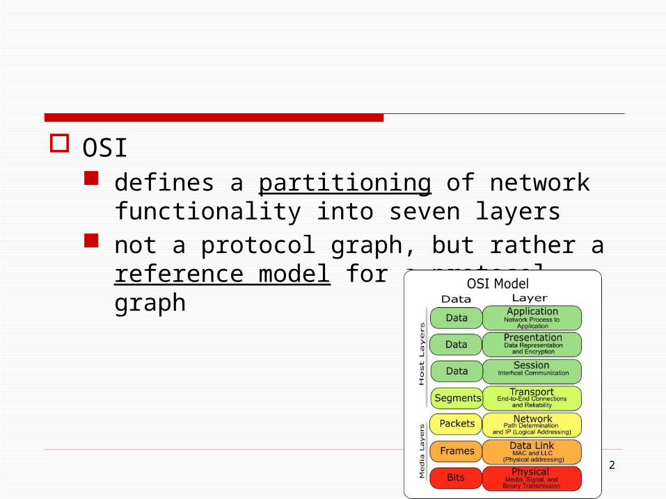
OSI defines a partitioning of network functionality into
seven layers not a protocol graph, but rather a reference model
for a protocol graph
2
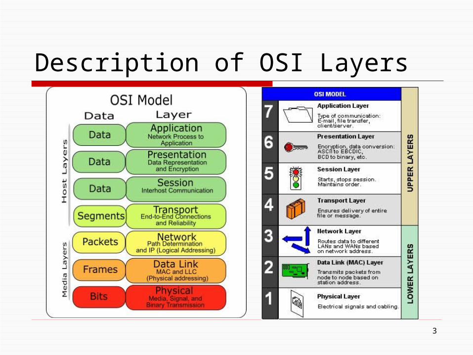
Description of OSI Layers
3

4
OSI Network Architecture
One or more nodeswithin the network
End host
Application
Presentation
Session
Transport
Network
Data link
Physical
Network
Data link
Physical
Network
Data link
Physical
End host
Application
Presentation
Session
Transport
Network
Data link
Physical
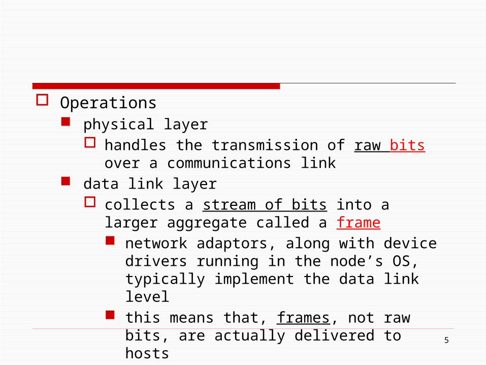
Operations physical layer
handles the transmission of raw bits over a communications link
data link layer collects a stream of bits into a larger aggregate called a
frame network adaptors, along with device drivers running
in the node’s OS, typically implement the data link level
this means that, frames, not raw bits, are actually delivered to hosts
5

network layer handles routing among nodes within a packet-switched
network at this layer, the unit of data exchanged among nodes is
typically called a packet rather than a frame [note]
the lower three layers are implemented on all network nodes, including switches within the network and hosts connected along the exterior of the network
6

transport layer implements a process-to-process channel the unit of data exchanged is commonly called a
message rather than a packet or a frame the transport layer and higher layers typically run only
on the end hosts and not on the intermediate switches or routers
7
session layer provides a name space that is used to tie together the
potentially different transport streams that are part of a single application
example it might manage an audio stream and a video
stream that are being combined in a teleconferencing application
8
presentation layer concerned with the format of data exchanged between
peers, for example, whether an integer is 16, 32, or 64 bits long whether the most significant byte is transmitted first
or last application layer
protocols include things like the File Transfer Protocol (FTP), which defines a protocol by which file transfer applications can interoperate
9
10
Internet Architecture (TCP/IP Architecture) The Internet architecture evolved out of experiences
with an earlier packet-switched network called the ARPANET
Both Internet and ARPANET were funded by the Advanced Research Projects Agency (ARPA), one of the R&D funding agencies of the U.S. Department of Defense
Internet and ARPANET were around before the OSI architecture, and the experience gained from building them was a major influence on the OSI reference model

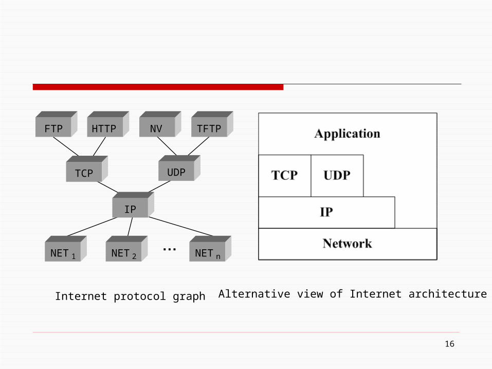
Internet a four-layer model the lowest level
a wide variety of network protocols: denoted NET1, NET2, and so on
these protocols are implemented by a combination of hardware (e.g., a network adaptor) and software (e.g., network device driver)
examples Ethernet or FDDI protocols
11
■ ■ ■
FTP
TCP UDP
IP
NET1 NET2 NETn
HTTP NV TFTP
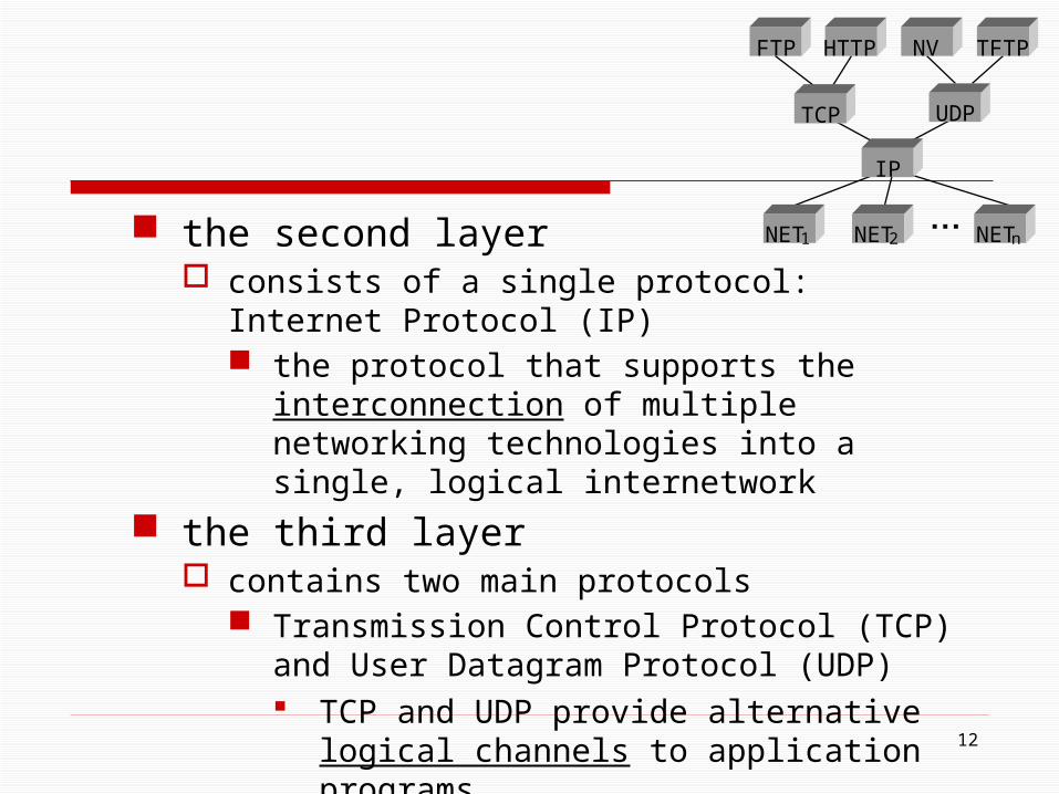
the second layer consists of a single protocol: Internet Protocol (IP)
the protocol that supports the interconnection of multiple networking technologies into a single, logical internetwork
the third layer contains two main protocols
Transmission Control Protocol (TCP) and User Datagram Protocol (UDP) TCP and UDP provide alternative logical channels
to application programs
12
■ ■ ■
FTP
TCP UDP
IP
NET1 NET2 NETn
HTTP NV TFTP

TCP provides a reliable byte-stream channel UDP provides an unreliable datagram delivery
channel (datagram may be thought of as a synonym for message)
in the language of the Internet, TCP and UDP are sometimes called end-to-end protocols, although it is equally correct to refer to them as transport protocols
13■ ■ ■
FTP
TCP UDP
IP
NET1 NET2 NETn
HTTP NV TFTP
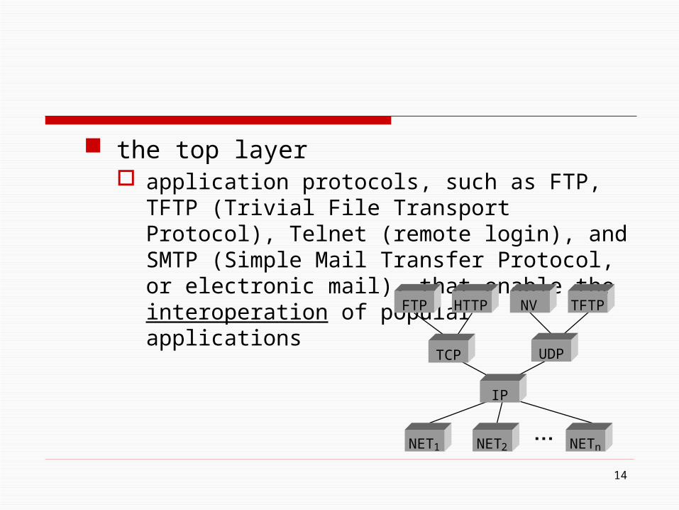
the top layer application protocols, such as FTP, TFTP (Trivial File
Transport Protocol), Telnet (remote login), and SMTP (Simple Mail Transfer Protocol, or electronic mail), that enable the interoperation of popular applications
14
■ ■ ■
FTP
TCP UDP
IP
NET1 NET2 NETn
HTTP NV TFTP
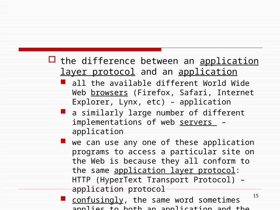
the difference between an application layer protocol and an application all the available different World Wide Web browsers
(Firefox, Safari, Internet Explorer, Lynx, etc) – application a similarly large number of different implementations of
web servers – application we can use any one of these application programs to access
a particular site on the Web is because they all conform to the same application layer protocol: HTTP (HyperText Transport Protocol) – application protocol
confusingly, the same word sometimes applies to both an application and the application layer protocol that it uses (e g., FTP)
15
16
■ ■ ■
FTP
TCP UDP
IP
NET1 NET2 NET n
HTTP NV TFTP
Internet protocol graph Alternative view of Internet architecture
17
1.4 Implementing Network Software
Application Programming Interface (Sockets) Protocol Implementation Issues

18
Network architectures and protocols specifications are essential things
But a good blueprint is not enough to explain the success of the Internet
19
What explains the success of the Internet Good architecture Much of its functionality provided by software
running in general purpose computers Electronic commerce, videoconferencing, packet
telephony With just a small matter of programming, new
functionality can be added readily The massive increase in computer power
20
Knowing how to implement network software is an essential part of understanding computer networks
Application Programming Interface (Sockets)
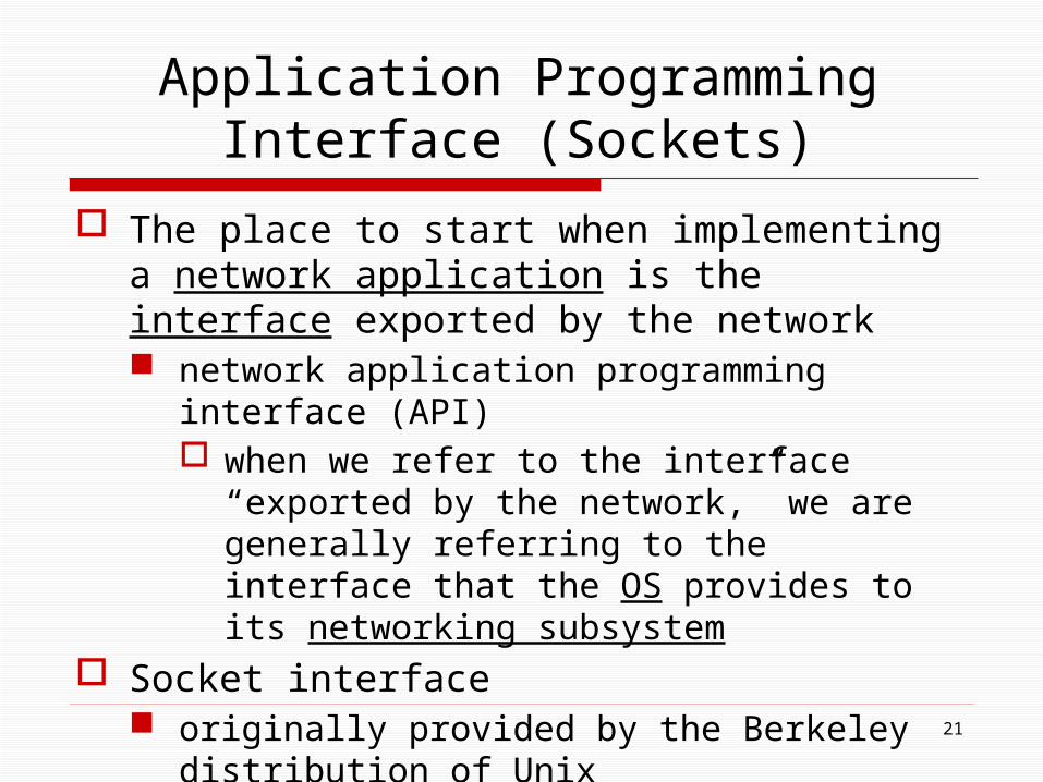
The place to start when implementing a network application is the interface exported by the network network application programming interface (API)
when we refer to the interface “exported by the network,” we are generally referring to the interface that the OS provides to its networking subsystem
Socket interface originally provided by the Berkeley distribution of Unix now supported in virtually all popular operating systems
21
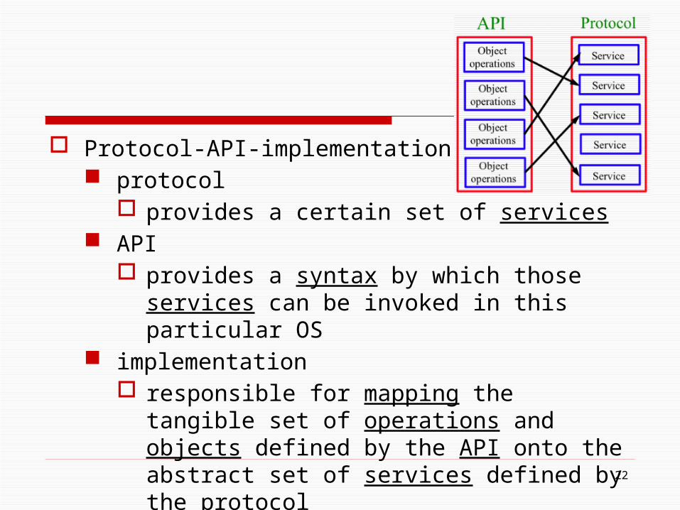
Protocol-API-implementation protocol
provides a certain set of services API
provides a syntax by which those services can be invoked in this particular OS
implementation responsible for mapping the tangible set of
operations and objects defined by the API onto the abstract set of services defined by the protocol
22
23
If you have done a good job of defining the interface, then it will be possible to use the syntax of the interface to invoke the services of many different protocols
Such generality was a goal of the socket interface
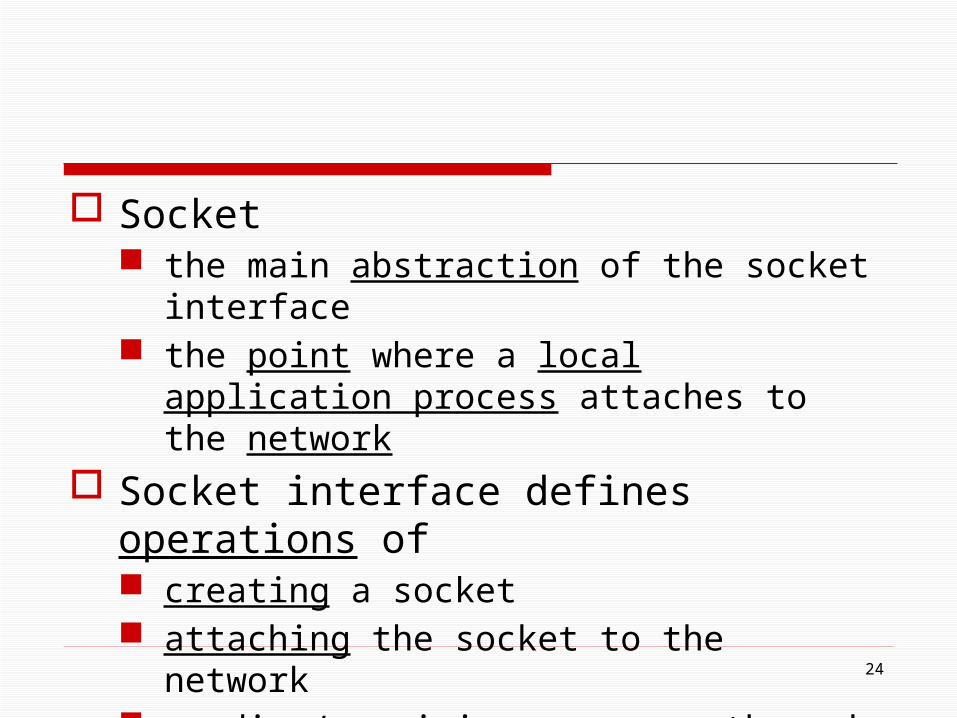
Socket the main abstraction of the socket interface the point where a local application process attaches
to the network
Socket interface defines operations of creating a socket attaching the socket to the network sending/receiving messages through the socket closing the socket
24
25
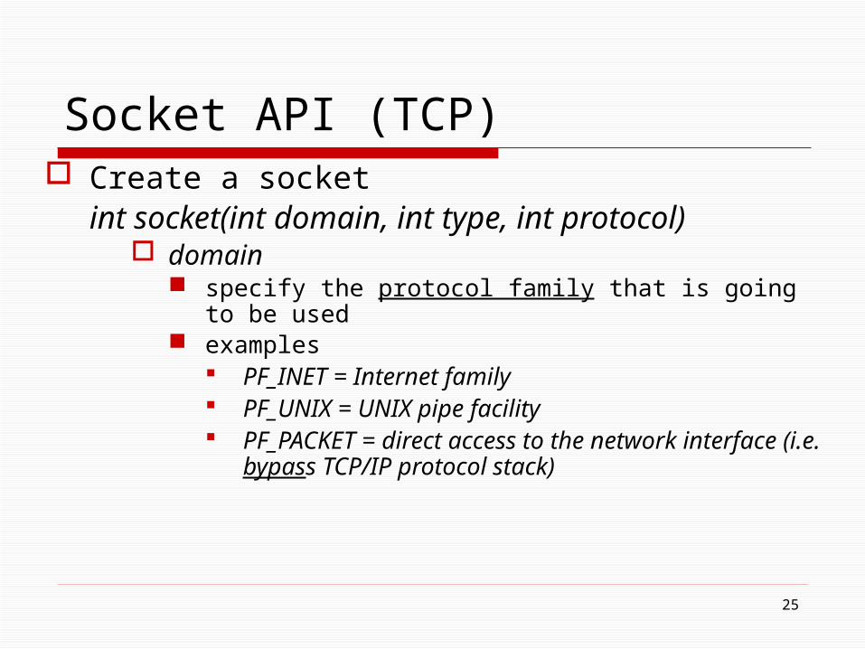
Socket API (TCP) Create a socket
int socket(int domain, int type, int protocol) domain
specify the protocol family that is going to be used examples
PF_INET = Internet family PF_UNIX = UNIX pipe facility PF_PACKET = direct access to the network interface (i.e.
bypass TCP/IP protocol stack)

type indicate the semantics of the communication examples
SOCK_STREAM = a byte stream SOCK_DGRAM =a message-oriented service, e.g.
UDP
protocol identify the specific protocol that is going to be used example
UNSPEC (Unspecified)
26
27
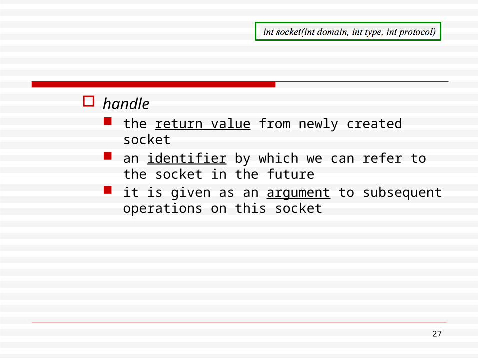
handle the return value from newly created socket an identifier by which we can refer to the socket in the
future it is given as an argument to subsequent operations on this
socket
28
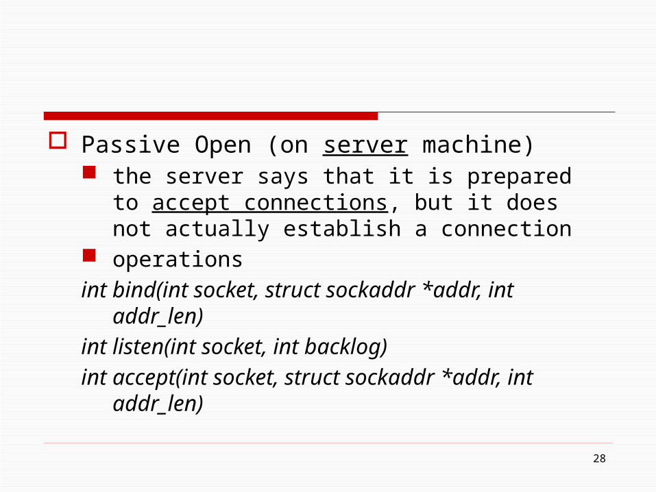
Passive Open (on server machine) the server says that it is prepared to accept connections,
but it does not actually establish a connection operations
int bind(int socket, struct sockaddr *addr, int addr_len)
int listen(int socket, int backlog)
int accept(int socket, struct sockaddr *addr, int addr_len)

bind operation binds the newly created “socket” to the specified
“address” (the server address) when used with Internet Protocols, “address” is a data
structure that includes the IP address of the server a TCP port number
used to indirectly identify a process usually some well-known number specific to the
service being offered; e.g., web servers commonly accept connections on port 80
29
listen operation defines how many connections can be pending on the
specified “socket” accept operation
carries out the passive open it is a blocking operation that does not return until a
remote participant has established a connection, and when it does complete
it returns a new socket that corresponds to this just-established connection
30
the “address” argument contains the remote participant’s address
when accept returns, the original socket that was given as an argument still exists and still corresponds to the passive open; it is used in future invocations of accept
31
32
Active Open (on client machine) it says who it wants to communicate with by invoking
“connect” operation
int connect(int socket, struct sockaddr *addr, int addr_len) connect operation
it does not return until TCP has successfully established a connection, at which time the application is free to begin sending data
“address” contains the remote participant’s address
Sending/Receiving Messages once a connection is established, the application processes
invoke the following two operations to send and receive data
operations
int send(int socket, char *msg, int mlen, int flags)
int recv(int socket, char *buf, int blen, int flags)
33

send operation it sends the given message over the specified socket
receive operation it receives a message from the specified “socket” into
the given “buffer” both “send” and “receive” take a set of “flags” that control
certain details of the operation
34
Section 1.4.2 Example Application
35
36
Protocol Implementation Issues
The way application programs interact with the underlying network is similar to the way a high-level protocol interacts with a low-level protocol
Ex., TCP needs an interface to send outgoing messages to IP, and IP needs to be able to deliver incoming message to TCP
37
Since we already have a network API(e.g., sockets), we might be tempted to use this same interface between every pair of protocols in the protocol stack
Certainly an option, in practice, the socket interface is not used in this way
Protocol Implementation Issues
Process model most operating systems provide an abstraction called a
process, or alternatively, a thread each process runs largely independently of other
processes OS is responsible for making sure that resources, such
as address space and CPU cycles, are allocated to all the current processes
38
the process abstraction makes it fairly straightforward to have a lot of things executing concurrently on one machine, e.g. each user application might execute in its own
process, and various things inside the OS might execute as other processes
when the OS stops one process from executing on the CPU and starts up another one, we call the change a context switch (time consuming)
39
Two types of process model process-per-protocol model process-per-message model
40

Process-per-protocol Process-per-message
(a) (b)
Interprocess messages
Process
Process
Process
Procedure calls
Process
Process
Process
Alternative process models

Process-per-protocol model each protocol is implemented by a separate process as a message moves up or down the protocol stack, it is passed
from one process/protocol to another the process that implements protocol i processes the message,
then passes it to protocol i-1, and so on one process/protocol passes a message to the next
process/protocol depends on the support the host OS provides for interprocess communication
42
typically there is a simple mechanism for enqueuing a message with a process
process-per-protoco1 model is sometimes easier to think about I implement my protocol in my process, and you implement
your protocol in your process cost
a context switch is required at each level of the protocol graph, typically a time consuming operation
43

Process-per-message model treats each protocol as a static piece of code associates the processes with the messages when a message arrives from the network, the OS dispatches
a process that it makes responsible for the message as it moves up the protocol graph
at each level, the procedure that implements that protocol is invoked, which eventually results in the procedure for the next protocol being invoked, and so on
for outbound messages, the applications process invokes the necessary procedure calls until the message is delivered
44
process-per-message model is generally more efficient a procedure call is an order of magnitude more efficient
than a context switch on most computer cost
only a procedure call per level
45
46
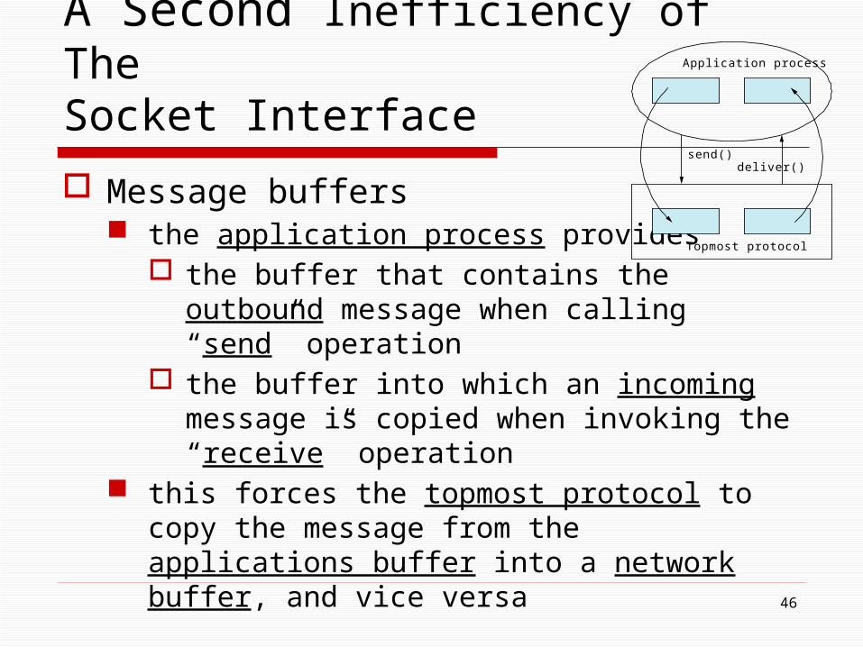
A Second Inefficiency of The Socket Interface
Message buffers the application process provides
the buffer that contains the outbound message when calling “send” operation
the buffer into which an incoming message is copied when invoking the “receive” operation
this forces the topmost protocol to copy the message from the applications buffer into a network buffer, and vice versa
send()deliver()
Topmost protocol
Application process

47
send()deliver()
Topmost protocol
Application process
Copying incoming/outgoing messages between application buffer and network buffer
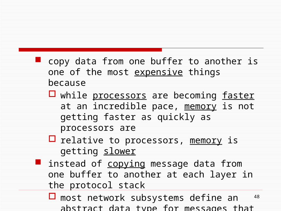
copy data from one buffer to another is one of the most expensive things because while processors are becoming faster at an incredible
pace, memory is not getting faster as quickly as processors are
relative to processors, memory is getting slower instead of copying message data from one buffer to
another at each layer in the protocol stack most network subsystems define an abstract data type
for messages that is shared by all protocols in the protocol graph
48

not only does this abstraction permit messages to be passed up and down the protocol graph without copying, but it usually provides copy-free ways of manipulating messages in other ways, such as adding and stripping headers fragmenting large messages into a set of small
messages reassembling a collection of small messages into a
single large message
49

the exact form of this message abstraction differs from OS to OS it generally involves a linked-list of pointers to
message buffers
50

51
Example message data structure
52
1.5 Performance
Performance metrics Bandwidth versus latency Delay ╳ bandwidth product High-speed networks Application performance needs
53
Up to this point, we have focused primarily on the functional aspects of a network
Computer networks are also expected to perform well The effectiveness of computations distributed over
the network often depends directly on the efficiency with which the network delivers the computation’s data
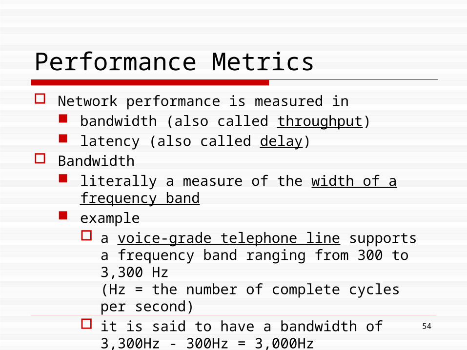
Performance Metrics Network performance is measured in
bandwidth (also called throughput) latency (also called delay)
Bandwidth literally a measure of the width of a frequency band example
a voice-grade telephone line supports a frequency band ranging from 300 to 3,300 Hz (Hz = the number of complete cycles per second)
it is said to have a bandwidth of 3,300Hz - 300Hz = 3,000Hz
54
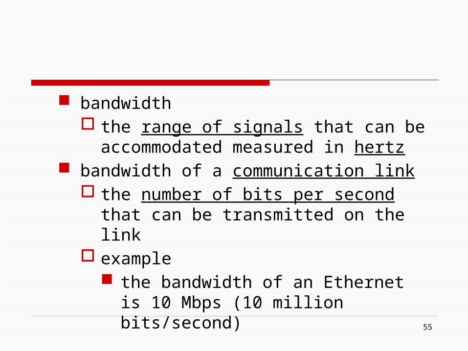
bandwidth the range of signals that can be accommodated
measured in hertz bandwidth of a communication link
the number of bits per second that can be transmitted on the link
example the bandwidth of an Ethernet is 10 Mbps (10
million bits/second)
55

bandwidth is sometimes thought in terms of how long it takes to transmit each bit of data example
on a 10-Mbps network, it takes 0.1 microsecond (μs) to transmit each bit
56
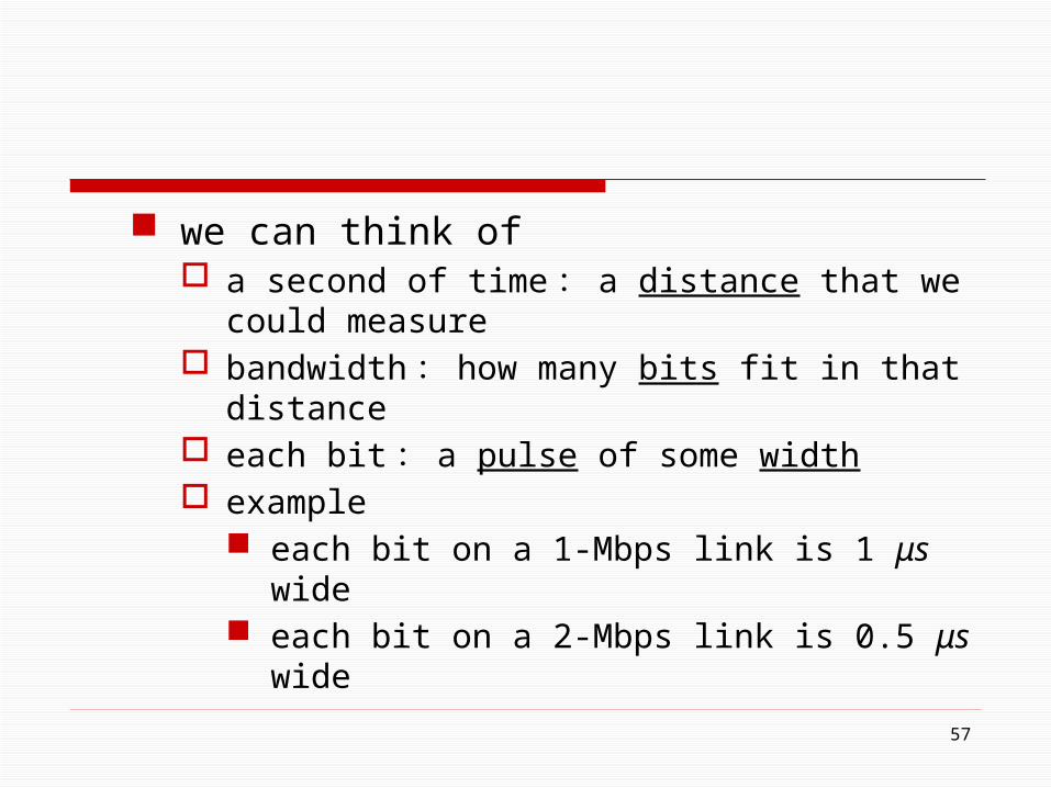
we can think of a second of time: a distance that we could measure bandwidth: how many bits fit in that distance each bit: a pulse of some width example
each bit on a 1-Mbps link is 1 μs wide each bit on a 2-Mbps link is 0.5 μs wide
57

58
Bits transmitted at a particular bandwidth can be regarded as having some width: (a) bits transmitted at 1 Mbps (each bit 1 μs wide); (b) bits transmitted at 2 Mbps (each bit 0.5 μs wide)
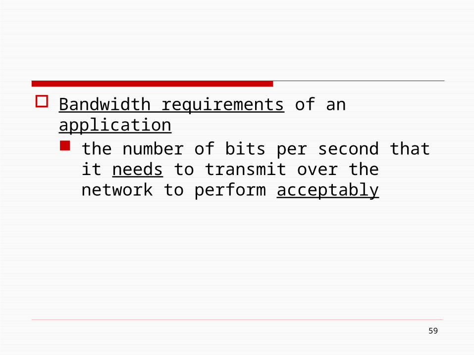
Bandwidth requirements of an application the number of bits per second that it needs to
transmit over the network to perform acceptably
59
a useful distinction might be made between the bandwidth that is available on the link and the number of bits per second that we can actually transmit over the link in practice
Throughput the measured performance of a system because of various inefficiencies of
implementation, a pair of nodes connected by a link with a bandwidth of 10 Mbps might achieve a throughput of only 2Mbps
60
61
Latency (delay) corresponds to how long it takes a message to
travel from one end of a network to the other (one-way)
measured strictly in terms of time example
a transcontinental network might have a latency of 24 milliseconds (ms)
i.e., it takes a message 24 ms to travel from one end North America to the other
Latency = Propagation delay + Transmit delay + Queuing delay Propagation delay = Distance / SpeedOfLight
light travels across different mediums at different speeds examples: 3.0 × 10⁸ m/s in a vacuum, 2.3 ×
108 m/s in a cable, and 2.0 × 10⁸ m/s in a fiber Transmit delay = Packet size / Bandwidth Queuing delay = the time the packet switches
takes to store packets for some time before forwarding them on an outbound link
62

Round-trip time (RTT) how long it takes to send a message from one end
of a network to the other and back
63
64
Bandwidth versus Latency
Relative importance (depends on applications) latency dominates bandwidth (latency bound)
example a client sends a 1-byte message to a server and
receives a 1-byte message in return assuming that no serious computation is involved
in preparing the response the application will perform much differently on a
transcontinental channel with a 100-ms RTT than ti will on an across-the-room channel with a 1-ms RTT

65
Bandwidth versus Latency
latency dominates bandwidth (latency bound) example
a client sends a 1-byte message to a server and receives a 1-byte message in return
transmit delay transmit delay for 1Mbps = 8 μs transmit delay for 100Mbps = 0.08 μs
1ms RTT vs 100ms RTT dominates 1Mbps vs 100Mbps
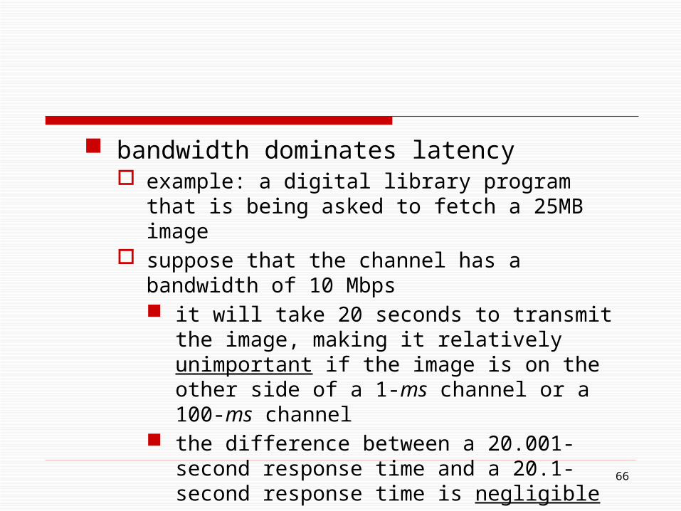
bandwidth dominates latency example: a digital library program that is being asked to
fetch a 25MB image suppose that the channel has a bandwidth of 10 Mbps
it will take 20 seconds to transmit the image, making it relatively unimportant if the image is on the other side of a 1-ms channel or a 100-ms channel
the difference between a 20.001-second response time and a 20.1-second response time is negligible
1Mbps vs 100Mbps dominates 1ms vs 100ms
66
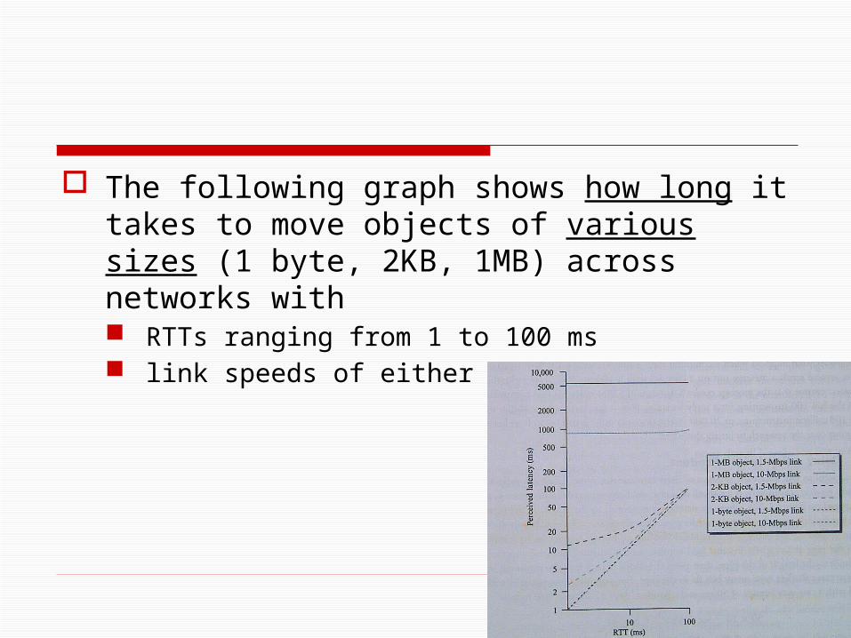
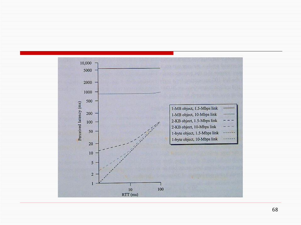
The following graph shows how long it takes to move objects of various sizes (1 byte, 2KB, 1MB) across networks with RTTs ranging from 1 to 100 ms link speeds of either 1.5 or 10 Mbps
67
68

69
Delay ╳ Bandwidth Product
Channel between a pair of processes as a hollow pipe
Latency (delay) the length of the pipe
Bandwidth the diameter of the pipe
Delay × bandwidth the volume of the pipe i.e. the maximum number of bits that could be in transit
through the pipe at any given instant
Bandwidth
Delay

70
Example a transcontinental channel with a one-way latency
of 50ms and a bandwidth of 45Mbps can hold 280KB (= 2.25 × 106 bits) of data
Bandwidth
Delay
71
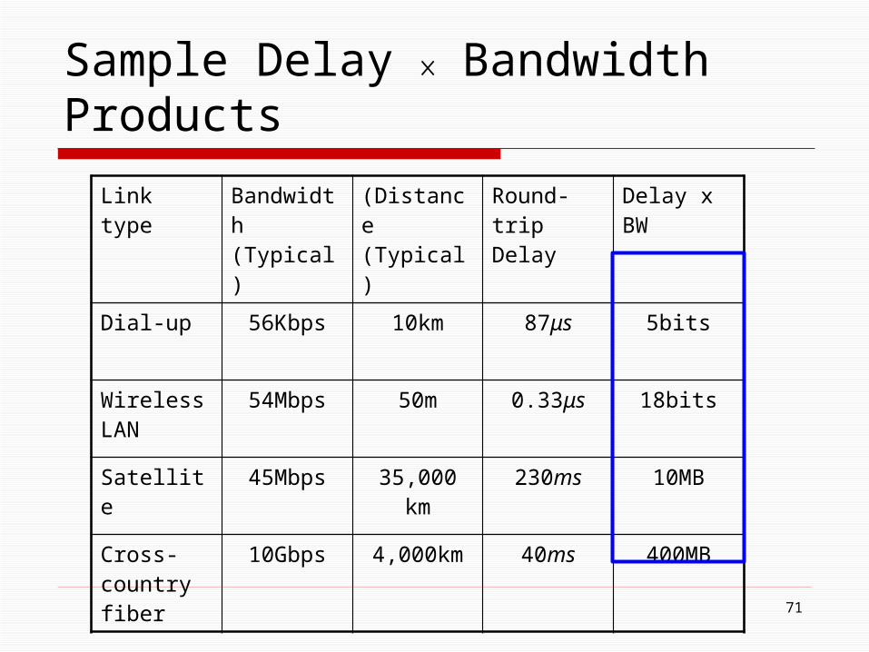
Sample Delay ╳ Bandwidth Products
Link type Bandwidth (Typical)
(Distance (Typical)
Round-trip Delay
Delay x BW
Dial-up 56Kbps 10km 87μs 5bits
Wireless LAN
54Mbps 50m 0.33μs 18bits
Satellite 45Mbps 35,000 km 230ms 10MB
Cross-country fiber
10Gbps 4,000km 40ms 400MB
72
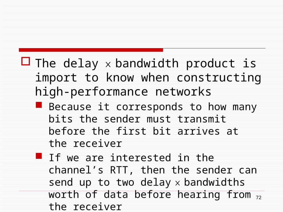
The delay ╳ bandwidth product is import to know when constructing high-performance networks Because it corresponds to how many bits the sender
must transmit before the first bit arrives at the receiver
If we are interested in the channel’s RTT, then the sender can send up to two delay ╳ bandwidths worth of data before hearing from the receiver
73
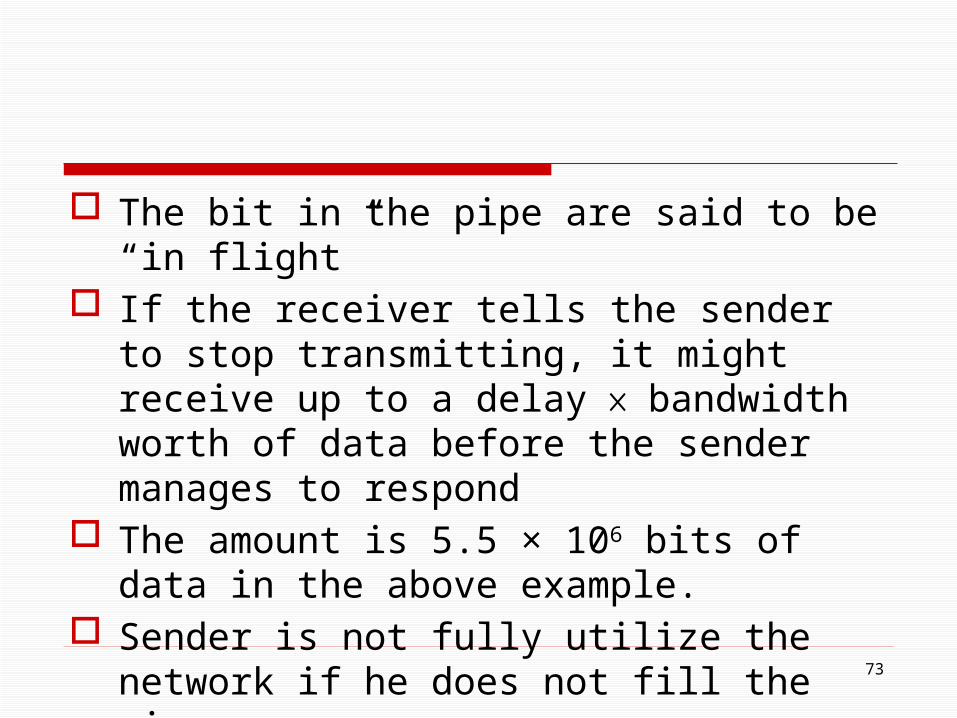
The bit in the pipe are said to be “in flight” If the receiver tells the sender to stop transmitting,
it might receive up to a delay ╳ bandwidth worth of data before the sender manages to respond
The amount is 5.5 × 106 bits of data in the above example.
Sender is not fully utilize the network if he does not fill the pipe
Most of time we are interested in the RTT scenario
74
High-Speed Networks
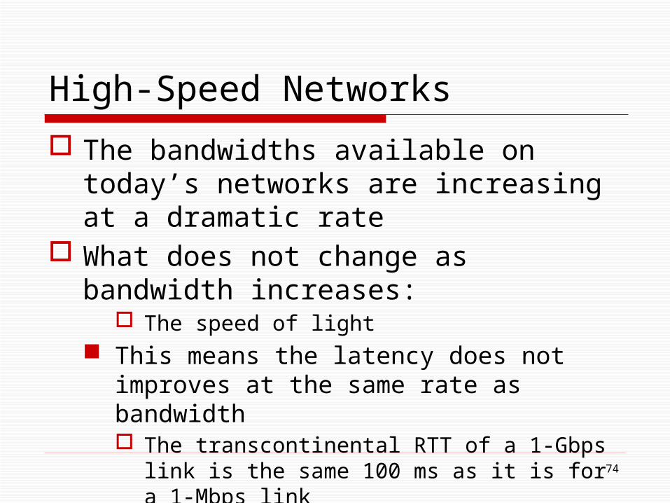
The bandwidths available on today’s networks are increasing at a dramatic rate
What does not change as bandwidth increases: The speed of light
This means the latency does not improves at the same rate as bandwidth The transcontinental RTT of a 1-Gbps link is the same
100 ms as it is for a 1-Mbps link
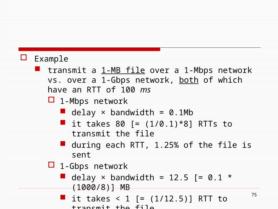
Example transmit a 1-MB file over a 1-Mbps network vs. over a 1-Gbps
network, both of which have an RTT of 100 ms 1-Mbps network
delay × bandwidth = 0.1Mb it takes 80 [= (1/0.1)*8] RTTs to transmit the file during each RTT, 1.25% of the file is sent
1-Gbps network delay × bandwidth = 12.5 [= 0.1 * (1000/8)] MB it takes < 1 [= (1/12.5)] RTT to transmit the file
75
76
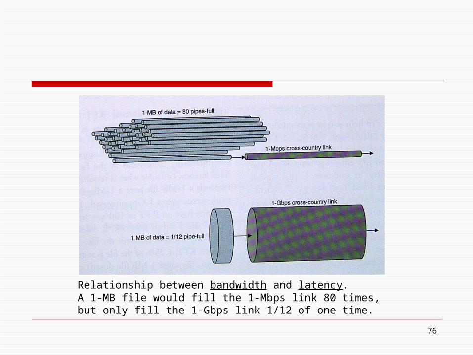
Relationship between bandwidth and latency. A 1-MB file would fill the 1-Mbps link 80 times, but only fill the 1-Gbps link 1/12 of one time.

77
The 1-MB file looks like a stream of data that needs to be transmitted across a 1-Mbps network, while it looks like a single packet on a 1-Gbps network
The more data a high-speed network can transmit during each RTT, the more significance a single RTT becomes
A file transfer taking 101 RTTs rather than 100 RTTs becomes significant

78
In other words, on a high-speed network, latency, rather than throughput, starts to dominate our thinking about network design

79
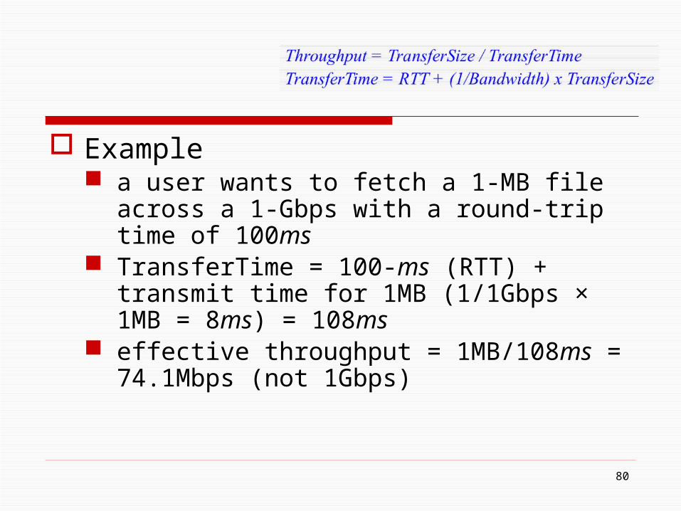
Throughput = TransferSize / TransferTime TransferTime = RTT + (1/Bandwidth) x TransferSize
TransferTime = one-way latency plus any additional time spent requesting or setting up the transfer
RTT = a request message being sent across the network and the data being sent back
in a high-speed network (infinite bandwidth), RTT dominates
80
Example a user wants to fetch a 1-MB file across a 1-Gbps
with a round-trip time of 100ms TransferTime = 100-ms (RTT) + transmit time for
1MB (1/1Gbps × 1MB = 8ms) = 108ms effective throughput = 1MB/108ms = 74.1Mbps
(not 1Gbps)
Discussions transferring a larger amount of data will help
improve the effective throughput where in the limit, an infinitely large transfer size
will cause the effective throughput to approach the network bandwidth
81
82
Application Performance Needs
Up to now, we have taken a network-centric view of performance We have talked in terms of what a given link or
channel will support The unstated assumption is the application
programs want as much bandwidth as the network can provide This is true of the aforementioned digital library
program that is retrieving a 25-MB image
Some applications are able to state an upper limit on how much bandwidth they need example
suppose one wants to stream a video image; that is one-quarter the size of a standard TV image; i.e., it has a resolution of 352 by 240 pixels
if each pixel is represented by 24 bits of information (24-bit color), then the size of each frame would be
(352 × 240 × 24)/8 = 247.5 KB
83
if the application needs to support a frame rate of 30 frames per second, then it might request a throughput rate of 75 Mbps
because the difference between any two adjacent frames in a video stream is often small, it is possible to compress the video by transmitting only the differences between adjacent frames
84
this compressed video does not flow at a constant rate, but varies with time according to factors such as the amount of action detail in the picture the compression algorithm
it is possible to say what the average bandwidth requirement will be, but the instantaneous rate may be more or less
85

86
Just knowing the average bandwidth needs of an application will not always suffice Transmits 1 Mb in a 1-second interval and 3 Mb in
the following 1-second interval, it will be of little help to a channel that was engineered to support no more than 2 Mb in any one second
It is possible to put an upper bound on how large a burst an application is likely to transmit
87
If this peak rate (burst) is higher than the available channel capacity, then the excess data will have to be buffered somewhere, to be transmitted later
Knowing how big of a burst might be sent allows the network designer to allocate sufficient buffer capacity to hold the burst
Discuss in Chap 6
88
Analogous in a similar way to an application’s bandwidth, an application’s delay requirements may be more complex than simply “as little delay as possible”
In the case of delay, it sometimes doesn’t matter whether the one-way latency is 100 or 500 ms as how much the latency varies from packet to packet
Jitter the variation in latency example
the source sends a packet once every 33 ms, as would be the case for a video application transmitting frames 30 times a second
if the packets arrive at the destination spaced out exactly 33 ms apart, then the delay experienced by each packet in the network was exactly the same
89

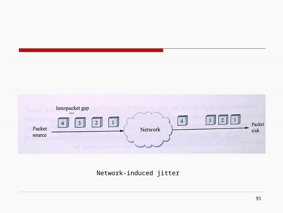
if the spacing between when packets arrive at the destination (interpacket gap) is variable, however, then the delay experienced by the sequence of packets must have also been variable, and the network is said to have introduced jitter into the packet stream
such variation is generally not introduced in a single physical link, but it can happen when packets experience different queuing delays in a multihop packet-switched network
90
91
Network-induced jitter

92
Relevance of jitter suppose that the packets being transmitted over the
network contain video frames, and in order to display these frames on the screen the receiver needs to receive a new one every 33 ms
if a frame arrives early, then it can simply be saved by the receiver until it is time to display it
if a frame arrives late, then the receiver will not have the frame it needs in time to update the screen, and the video quality will suffer; it will not be smooth

93
if the receiver knows the upper and lower bounds on the latency that a packet can experience, it can delay the time at which it starts playing back the video (i.e., displays the first frame) long enough to ensure that in the future it will always have a frame to display when it needs it
the receiver delays the frame, effectively smoothing out the jitter, by storing it in a buffer