osu hyslop - recycle.oregonstate.edurecycle.oregonstate.edu/sites/fa.oregonstate.edu/files/...that a...
TRANSCRIPT

Agricultural Assessment Report
For
OSU Hyslop 3455, NE Granger
Corvallis, OR 97330
ENERGY / EFFICIENCY CENTER


OREGON STATE UNIVERSITY
ENERGY / EFFICIENCY CENTER
Assessment Report No. AG-1000-A
August 1, 2008
Joseph F. Junker, Assistant IAC Director ________________________________
Mikhail Jones, Lead Analyst ________________________________
Assessment Participants
Nathan Keeley Energy Analyst Carl Moen Energy Analyst Elsie Delande Energy Analyst and Safety Officer
Dr. George Wheeler Joseph F. Junker IAC Director Assistant Director Batcheller Hall 341 Batcheller Hall 344 Corvallis, OR Corvallis, OR 97331-2405 97331-2405 (541) 737-2515 (541) 737-5034


PREFACE The work described in this report is a service of the Oregon State University Energy/Efficiency Center. The primary objective of the E/EC agricultural assessment is to identify and evaluate opportunities for energy conservation, waste minimization, and productivity improvements through visits to agricultural sites. Data is gathered during a one-day site visit and assessment recommendations (ARs) are identified. Some ARs may require additional engineering design and capital investment. When engineering services are not available in-house, we recommend that a consulting engineering firm be engaged to provide design assistance as needed. In addition, since the site visits by E/EC personnel are brief, they are necessarily limited in scope and a consulting engineering firm could be more thorough. We believe this report to be a reasonably accurate representation of energy use, waste generation, production practices, and opportunities in your facility. However, because of the limited scope of our visit, the Oregon State University Energy/Efficiency Center cannot guarantee the accuracy, completeness, or usefulness of the information contained in this report, nor assumes any liability for damages resulting from the use of any information, equipment, method or process disclosed in this report. Pollution prevention recommendations are not intended to deal with the issue of compliance with applicable environmental regulations. Questions regarding compliance should be addressed to either a reputable consulting engineering firm experienced with environmental regulations or to the appropriate regulatory agency. Clients are encouraged to develop positive working relationships with regulators so that compliance issues can be addressed and resolved. The assumptions and equations used to arrive at energy, waste, productivity, and cost savings for the recommended ARs are given in the report. We believe the assumptions to be conservative. If you would like to revise the assumptions you may follow the calculation methodologies presented to develop your own adjusted estimates of energy, waste, productivity, and cost savings. Please feel welcome to contact the E/EC if you would like to discuss the content of this report or if you have another question about energy use or pollution prevention. The E/EC staff that visited your site and prepared this report is listed on the preceding page.

TABLE OF CONTENTS
1. Introduction ...........................................................................................................................1 2. Narrative ................................................................................................................................2 3. Assessment Recommendations .............................................................................................5 AR No. 1 Lighting ............................................................................................5 Elsie Delande AR No. 2 Dryer Fan Controls ..........................................................................5 Carl Moen AR No. 3 Turn Off Dryer .................................................................................5 Carl Moen AR No. 4 Boiler Tune ......................................................................................6 Carl Moen 4. Other Measures Considered ..................................................................................................7 OMC No. 1 Boiler Economizer ...........................................................................7 Carl Moen OMC No. 2 Chemical Hood Filter .......................................................................7 Carl Moen OMC No. 3 Dryer Economizer ............................................................................7 Carl Moen OMC No. 4 Blower Sizing...................................................................................8 Carl Moen OMC No. 5 Tractor Operation .............................................................................8 Mikhail Jones OMC No. 6 Fuel Tank Cover ..............................................................................8 Mikhail Jones OMC No. 7 Low Pressure Irrigation ....................................................................9 Mikhail Jones OMC No. 8 Swamp Cooler Control ....................................................................9 Elsie Delande 5. Energy Balance ....................................................................................................................11 Mikhail Jones 6. Calculation Methodology ....................................................................................................15 AR No. 1 Lighting ..........................................................................................15 AR No. 2 Dryer Fan Controls ........................................................................22 AR No. 3 Turn Off Dryer ...............................................................................27 AR No. 4 Boiler Tune ....................................................................................32 A. Utilities Appendix ...............................................................................................................37 B. Lighting Appendix ..............................................................................................................43

1. INTRODUCTION This report describes how energy is used in your plant, and includes our recommendations on cost effective steps you can take to reduce your energy and waste costs and increase productivity. The contents are based on our recent visit to your plant. The report is divided into 6 major sections and 2 appendices: 1. Introduction. The purpose, contents and organization of the report are described in this
section. 2. Narrative. This section contains a description of the processes at your site and efficiency
measures we discussed. 3. Assessment Recommendations. This section contains our Assessment Recommendations
(AR), briefly highlights the current and proposed systems and summarizes the cost savings available upon implementation. Some of our recommendations will require a significant investment to implement, while others will cost little or nothing.
4. Other Measures Considered. These measures are just estimations made with limited data
or analysis because; (1) we were unable to obtain the information necessary to estimate savings or cost accurately; (2) the measure would adversely affect production. Some measures are included in response to specific questions you raised during the plant visit, but which do not appear to be feasible.
5. Energy Balance. Your energy use and waste generation costs, productivity, energy, and
waste savings, are summarized here. 6. Calculation Methodology. This section includes the detailed calculations for the
Assessment Recommendations (AR). It includes any data that was collected during the audit, assumptions we use to estimate savings, our estimate of the implementation cost, and the simple payback of implementation.
Appendix A: Utilities. Your utility bills and energy use by process are summarized and plotted in detail. Due to the changes in rate schedules and adjustments our calculations are an approximation and may not be exactly consistent with your bills. When available, we also include water and solid waste bills. Appendix B: Lighting. The number and type of lighting fixtures are recorded for each area. This appendix also includes the Lighting Worksheet Definitions, which describe the symbols and terminology used in our lighting calculations. The lighting power and annual energy use for each plant area are summarized in the Lighting Inventory worksheet.
1
2. NARRATIVE This section includes a summary of processes and equipment used at your site and brainstorm ideas discussed on site.
Processes: Below is a summary of the processes at your site.
• Dryer Rooms: The dryers are used to remove moisture from multiple plant sources. The materials are stacked on the floor of the drying room to ensure the best air flow from the dryer heaters through the sacks of material.
• Seed Separation: There are two parts to seed separation. One is the general farm seed separator. This has 5 seed separators, used by various groups for different types of seeds. The other is the seed separation room that is used by the wheat evaluation group. They have their own separators that are specifically used for wheat.
• Wheat Evaluation area: This area is solely used by the wheat evaluation group. They
sort, clean, evaluate and store wheat grains in this area. The wheat is gathered from multiple locations around the state.
• Test plots of Wheat: These are small areas (less than 100 ft sq.) that are the test growing
areas for various strains of wheat from the evaluated grains and seeds. Equipment: Below is a list of your large equipment and its application.
• Boiler: The boiler is used to create steam used in the dryer system.
• Seed separators: These remove the husks, stalk and any loose material from the seed head via a series of tines and scrubbers.
• Blowers: Two blowers remove dust and debris from the two seed cleaning rooms.
• Tractors: Many different types of tractors were observed: General use Tractors,
Combines, and their various attachments (Spreader, Sprayer, Mower)
• Air compressor: A 5 hp air compressor provides air to operate all dryer controls and for certain tools in the maintenance shop.
Brainstorm Ideas: Below is a list of ideas we developed during the assessment and considered recommending in our report.
• Install T-8 lighting: Upgrade your current incandescent lights to T-8’s for increased efficiency, reducing your electricity usage.
• Boiler Tune: Tune your boiler (i.e. the air/fuel ratio optimized) for efficiency to reduce natural gas consumed.
2

• Boiler Economizer: Use hot exhaust air to preheat cool inlet air. This raises boiler efficiency reducing fuel use.
• Dryer Economizer: Install an economizer to preheat cool incoming dryer air with hot
exhaust air prior to final steam heating. This will raise heater efficiency.
• Dryer Moisture Migration: Automatically adjust the heat and air flow of the dryer to maximize effectiveness of each drying cycle. The first part of the drying cycle removes surface moisture (requiring high air flow), the second part is waiting for the moisture to migrate to the surface before the air can absorb it (only requiring low air flow).
• Dryer- Stopping: Ensure dryers turn off when a batch of material is done. This can be
set up to occur automatically.
• Oversized Blower: Reduce the seed room blower size to more appropriately fit your need.
• Greenhouse: Improve greenhouse energy efficiency.
• Swamp Cooler Controls (Timer or Thermostat): Automatically turn the swamp cooler
off and on to maintain desired greenhouse temperatures.
• Irrigation Pump Efficiency: Reduce irrigation pumps energy consumption.
• Low Pressure Irrigation: Use a low pressure irrigation system to reduce the electricity required by the well pump.
• VSD: Chang pump speed (rpm) to best optimize the volume of water to the pressure
needed.
• Fuel: Reduce fuel consumption.
• Cover Tanks: Cover fuel tanks to reduce fuel vaporization as the tank warms up in the sun. This will reduce the loss of fuel to atmosphere.
• Tractor Operation: Change the governor settings of the tractors to operate at a lower
RPM to save fuel.
• Chemical Hood Filter: Best Practice - Your chemical hoods are operating a low differential pressure, leading to a high efficiency.
• Electric Tractors: Use an electric powered tractor for light duty operations in the field.
This could be irrigation changes, small plantings, or minor projects. This would reduce the fuel consumption of a large tractor or vehicle needed to perform the same task.
3

4
• People Movers: replace a regular vehicle with an electric runabout (golf cart) or electric vehicle for light duty projects. From a run to town in an electric vehicle to checking the water amount from irrigation, this removes a conventionally fueled vehicle from operation, saving the fuel for that vehicle.
• Refrigeration System Efficiency: Best Practice – We observed that the refrigeration
system was well insulated, the door stays shut, the fan is fairly right sized, and the approach temperature is 20-25 degrees.
Recommendations Summary: Recommendations that we were able to quantify into cost savings, implementation cost and energy saved are summarized in the following table.
Assessment Recommendation Summary Energy Cost Implementation Payback AR# Description (MMBtu) Savings Cost* (years) 1 Lighting 11.6 $475 $9061,2 1.9 2 Dryer Fan Controls 347.3 $3,755 $4,390 1.2 3 Turn Off Dryer 165.2 $1,576 $4,390 2.8 4 Boiler Tune 1.4 $12 $500 41.0 Totals 525.5 $5,818 $10,186 1.8
* Implementation Cost in this column represents your final cost after any applicable incentives as noted 1 This final cost is reduced by an Oregon Department of Energy Business Energy Tax Credit. 2 This final cost is reduced by Energy Trust of Oregon Incentives. Total savings are the sum of the savings for each recommendation. Some of the recommendations may interact. Therefore, actual savings may be less than the total indicated above. In our calculations we indicate where we have assumed that other recommendations will be implemented in order to provide a realistic estimate of actual savings. When either one or another recommendation can be implemented, but not both, we have included the recommendation we recommend in this table and the alternate recommendation in a later section, Other Measures Considered. Total savings, including interactions among recommendations, can be better estimated after you select a package of recommendations.

3. ASSESSMENT RECOMMENDATIONS
Lighting While visiting your facility we inventoried your lighting. After consulting with facility personnel we determined that some areas with incandescent fixtures could be replaced with T-8 florescent fixtures for higher lamp efficiency. Increasing lamp efficiency will reduce electricity costs, as well as associated labor and maintenance costs. Lighting energy use in these areas will be reduced by over 2.7%. As detailed in the Lighting - Calculation Methodology, there is a 1.9 year payback with a $906 implementation cost and $475 annual savings.
Dryer Fan Controls
Currently the dryers are run at full flow during the entire drying cycle. We recommend installing a Proportional Integral Derivative (PID) controller on the dryer fan motors to control fan speed based on the change in relative humidity within the dryers. By controlling fan speed in this manner, annual fan electrical energy consumed will be reduced by 21% and annual boiler energy consumed will be reduced by 21%. As detailed in the Dryer Fan Controls - Calculation Methodology, there is a 1.2 year payback with a $4,390 implementation cost and $3,755 annual savings.
Turn Off Dryer Currently dryers are left on until someone remembers to turn them off. A more efficient method is to use a fan controller with a programmed “recipe” which turns off the fan based on the air moisture content. We recommend installing a Proportional Integral Derivative (PID) controller on the dryer fan motors to automatically turn off the dryer fans. By controlling fan operating hours in this manner, annual fan electric energy consumption will be reduced by 10% and annual boiler energy consumption will be reduced by 10%. As detailed in the Dryer Fan Controls - Calculation Methodology, there is a 2.8 year payback with a $4,390 implementation cost and $1,576 annual savings.
5

Boiler Tune During our site visit, we performed a flue gas analysis on the boiler. The analysis indicated that oxygen levels were at approximately 5%. This indicates slightly more excess air than required. Excess air carries heat up the stack and reduces boiler efficiency. If you have the opportunity, perform a tune on your boiler to maintain excess oxygen at the recommended level of 4%. If oxygen is maintained at recommended levels, combustion efficiency will stay high, reducing fuel usage. This will increase the efficiency of the steam system, reducing fuel consumption and energy costs. As detailed in the Boiler Tune - Calculation Methodology, there is a 41.0 year payback with a $500 implementation cost and $12 annual savings.
6

4. OTHER MEASURES CONSIDERED
Boiler Economizer Currently, steam condensate is returned for boiler feedwater. While this reduces boiler operation costs, more savings are possible by implementing a boiler economizer. A boiler economizer redirects the flue gas from the boiler through a heat exchanger to pre-heat the boiler feedwater. By increasing the temperature of the feedwater, the boiler uses less energy turning that water into steam. Pre-heating the incoming feedwater to the boiler with an economizer will recover a large amount of the energy associated with your process heating. Installing the hot tank heat exchanger could save 10% of your total natural gas costs.
Chemical Hood Filter
There is a chemical hood used by the wheat seed group to coat tested seeds in a chemical. The hood filter differential pressure is an indication of how hard the fan has to work to pull air through the filter. The higher the differential pressure, the higher the energy use of the fan. We recommend replacing the filter as differential pressure increases. The filter differential pressure was measured to be low, which shows that the filter is trapping the material as it should and not restricting the fan’s operation. This leads to a Best Practice for filter maintenance and energy consumption.
Dryer Economizer
Currently, hot air is taken from inside the building, passes through the dryer, and then is exhausted outside the building. While taking air from inside the building can pre-heat the air, savings are possible by implementing a dryer economizer. A dryer economizer redirects the moist exhaust air from the dryer through a heat exchanger to pre-heat the incoming air to the dryer. By increasing the temperature of the incoming air, the heater uses less energy from the boiler. Pre-heating the incoming air to the heater with an economizer will recover a large amount of the energy associated with your drying process. Installing the air to air heat exchanger could save 10% of your total natural gas costs.
7

Blower Sizing The blower is used to remove seed shells and husks from the seed cleaning machines. It draws suction on the machines and then discharges to a cyclone filter. The seed machines have two different ducting sizes, 4 inch and 6 inch diameter, the blower supply ducting has over 20 individual connections for the different seed cleaning machines. The ducting also has open ends to allow for sufficient air flow when only a few cleaning machines are operating. We recommend reducing the size of the blower to more effectively utilize the fan efficiency, also close the open ends of the ducting. This will reduce the energy costs of the fan, and reduce the non-productive air from the open ends of the ducting. This could save over 10% of the electrical costs of the blower.
Tractor Operation
Tractor operators can obtain a number of forward speeds by adjusting the transmission gear ratio while maintaining the same engine RPM. Within each gear there is further adjustment available with the governor setting lever. Most tractor field speeds are determined by the implement and not by the tractor power available. While visiting your facility we were informed that most operators run the tractors at full throttle using the transmission gear ratio to vary speed. Significant increases in fuel efficiency are expected if the governor speed lever is reduced and a faster gear ratio is selected. This is particularly true in operating conditions of less than half load. Additional savings are available by keeping a maintenance schedule, proper ballasting, and proper tire inflation. Savings of up to 4 percent in fuel can be achieved by keeping a maintenance schedule and replacing air and oil filters as necessary. We were unable to determine how much savings would be available because not enough data on how the tractors are currently operated was available, but with no implementation cost the savings will be immediate and significant.
Fuel Tank Cover
Storage tanks can lose a considerable amount of fuel due to evaporation and leaks. In extreme cases up to 40 percent of a tanks capacity can be lost per year from evaporation. This can be reduced to around 0.5 percent by following these tips:
• Keep fuel tanks well shaded. • Tank should be aluminum or white to reflect the suns heat and reduce evaporation. • Use pressure-relief vacuum caps instead of conventional caps. • Lock unattended fuel tanks • Regularly inspect tanks for leaks. During inspections tighten all fittings.
Although we could not develop an exact number for savings associated with this project we do recommend putting a cover over fuel tanks as savings could be significant.
8

Low Pressure Irrigation
While visiting your facility we were informed that you use a standard irrigation system. This is less energy efficient than a low pressure irrigation system. Low pressure irrigation systems generally operate between 10 and 50 percent of standard pumping pressure. These systems can reduce electricity costs associated with pumping between 10 and 35 percent. One-time cash incentives may also be available on a per acre basis depending on your location. After further investigation we determined that such a system would be economically and practically unfeasible for your current size and layout. In order for such a system to work you need either a network of linears or central pivots, because of your small plot size neither of these systems will work.
Swamp Cooler Control
While visiting your facility we were informed that the greenhouses were cooled using fans blowing air through a water curtain. We were also informed that one of the greenhouses became overheated which in turn caused the wiring boxes to melt. Currently, the cooling system runs continuously and is only turned off in the event that there is no experiment running. Installing controls that monitor the temperature of the greenhouses would allow the cooling system to turn off when the greenhouses reach the temperature necessary for the project, and to turn on before the greenhouse overheats. Installing vents with screens to keep out particulates, as well as temperature controls would also help with cooling the space. These vents can only be installed on the house-shaped greenhouse and not the half cylinder greenhouses because you need a flat side for vent installation. We are unable to determine how much the savings for this project might be because there is no data on how much energy is being used currently and how much we could reduce energy use by. The installation costs for temperature controls are $432 which includes material and labor costs. The material costs include 6 thermostats, one for each fan, at a cost of $22/thermostat for a total material cost of $132. Labor costs include installation of each thermostat which we assume will take 1hr/thermostat at an electrician wage of $50/hr for a total installation cost of $300.
9

10

5. ENERGY BALANCE
Your energy use and waste generation costs, productivity, energy, and waste savings, are summarized here.
END USE SUMMARYAverage Electricity Cost: $0.06566 /kWhAverage Natural Gas Cost: $0.89730 /therm
$8.97 /MMBtu
ELECTRICITYUSE UNIT 106 Btu ENERGY % COST COST%
Irrigation Well Pump # 1 2,827 kWh 10 3.1% $186 3.1%Irrigation Well Pump # 2 1,666 kWh 6 1.8% $109 1.8%Domestic Well Pump 231 kWh 1 0.3% $15 0.3%Boiler Fan Motor 481 kWh 2 0.5% $32 0.5%Boiler Condensate Pump 160 kWh 1 0.2% $11 0.2%Dryer Fan #1 3,844 kWh 13 4.2% $252 4.2%Dryer Fan #2 3,890 kWh 13 4.3% $255 4.3%Dryer Fan #3 5,766 kWh 20 6.3% $379 6.3%Dryer Fan #4 5,766 kWh 20 6.3% $379 6.3%Seed Cleaner #1 130 kWh 0 0.1% $9 0.1%Seed Cleaner #2 58 kWh 0 0.1% $4 0.1%Seed Cleaner #3 58 kWh 0 0.1% $4 0.1%Seed Cleaner #4 130 kWh 0 0.1% $9 0.1%Seed Cleaner #5 58 kWh 0 0.1% $4 0.1%Seed Cleaner #6 58 kWh 0 0.1% $4 0.1%Dryer Fan Walk In #1 5,766 kWh 20 6.3% $379 6.3%Dryer Fan Walk In #2 14,415 kWh 49 15.9% $946 15.9%Refrig Unit 1,422 kWh 5 1.6% $93 1.6%Blower 1,153 kWh 4 1.3% $76 1.3%Lighting (See Lighting Inv.) 18,480 kWh 63 20.3% $1,213 20.3%Miscellaneous 24,554 kWh 84 27.0% $1,612 27.0%TOTALS 90,913 kWh 310 100.0% $5,969 100.0%
NATURAL GASUSE UNIT 106 Btu ENERGY % COST COST%
Boiler 11,160 therm 1,116 98.4% $10,014 98.4%Miscellaneous 185 therm 18 1.6% $166 1.6%TOTALS 11,345 therm 1,134 100.0% $10,180 100.0%
FUEL SUMMARYUSE UNIT 106 Btu ENERGY % COST COST%
ELECTRICITY 90,913 kWh 310 94.4% $5,969 97.3%NATURAL GAS 185 therm 18 5.6% $166 2.7%TOTALS 329 100.0% $6,135 100.0%
11

12

13

14

6. CALCULATION METHODOLOGY
AR No. 1 Lighting
Calculation Methodology
Recommendation Replace incandescent fixtures with T-8 fixtures. This will reduce your energy consumption by 2.7%.
Assessment Recommendation Summary Energy Energy Cost Implementation Payback
(MMBtu) (kWh) Savings Cost (years) 11.6 3,390 $475 $1,711 3.6
*1 kWh = 3,410 Btu
Estimated Incentive Summary
ETO1 BETC2 Net Net
Payback Incentive Tax Credit Cost (years)
$407 $398 $906 1.9 1 Energy Trust of Oregon Incentive 2 Oregon Department of Energy Business Energy Tax Credit Data Collected Summary
During our facility visit we inventoried all current lighting and were able to identify some areas where lighting improvements could be made. The following table summarizes current and proposed lighting.
Lighting Summary Current Proposed
Location Fixture Quantity Fixture QuantityDrying/Storage 200W Incandescent 13 4 ft T-8 10 Loading 200W Incandescent 4 4 ft T-8 3 WP Seed Cleaning 200W Incandescent 4 4 ft T-8 3
15

Savings Analysis Energy and maintenance savings for replacing the 200W incandescent fixtures with 4ft T-8 fixtures are calculated using the Replace Incandescent Fixtures worksheet that follows this calculation summary. Lighting worksheets’ terminology is described in Appendix B. Demand savings are estimated using power, current fixture input watts, proposed fixture input watts, and operating hours per year. Demand cost savings are estimated with an incremental demand cost of $3.12/kW. The T-8 fixtures in the Drying/Storage area are taken as an example. CS1 = Demand Cost Savings = DS x DC x MY = 2.0 kW/mo x $3.12 /kW x 12 mo/yr = $75 /yr Where, DC = Incremental Demand Cost = $3.12 /kW MY = Months per year = 12 mo/yr DS = Demand Savings = CD – PD = 2.6 kW/mo – 0.6 kW/mo = 2.0 kW/mo Where, CD = Current Demand = 2.6 kW/mo PD = Proposed Demand = 0.6 kW/mo Energy savings are estimated using power, current fixtures, proposed fixtures and operating hours per year. Energy cost savings are estimated with an incremental energy cost of $0.06566 / kWh; CS2 = Energy Cost Savings = ES x EC = 2,400 kWh/yr x $0.06566 /kWh = $158/yr Where, EC = Incremental Energy Cost = $0.06566 /kWh
16

ES = Energy Savings = CE – PE = 3,120 kWh/yr – 720 kWh/yr = 2,400 kWh/yr Where, CE = Current Energy Consumption = 3,120 kWh/yr PE = Proposed Energy Consumption = 720 kWh/yr Replacing incandescent fixtures with T-8 fixtures will decrease maintenance costs, as estimated in the Replace Incandescent Fixtures tables at the end of this calculation methodology. The maintenance material savings total $67/year, while maintenance labor savings total $64/year. Therefore, the total maintenance savings sum up to approximately $131/year. Total annual cost savings are summarized in the following table:
Saving Summary Energy
Source Quantity Units MMBtu Cost Demand 3.2 kW $121 Energy Use 3,390 kWh 11.6 $223 Maintenance Material $67 Maintenance Labor $64 Total 11.6 $475
Cost Analysis The cost of replacing the incandescent fixtures with T-8 fixtures is based on the cost of material and installation per fixture. There are a total of 16 T-8 fixtures that need to be installed to replace 21 incandescent fixtures. We estimate that it will take an electrician one hour to install each fixture at a wage of $50/hr. The implementation costs are summarized in the following table:
Cost Summary Item Units Needed $/Unit Total $
4 Ft T-8 Fixtures 16 Fixtures $56.95 $911 Electrician 16 Hours $50.00 $800 Total $1,711
17

Incentive Summary Energy Trust cash incentives are available to help pay for implementation of energy saving measures if they save at least 10% of the energy used in a system. Incentives can be anticipated to equal the minimum of 25% of total project cost, $0.12 per kWh saved, or $1 per therm saved. CI = ETO Cash Incentive = Minimum of TES x $0.12 or 0.25 x TC = Minimum of 3,390x $0.12 or 0.25 x $1,711 = Minimum of $407 or $428 = $407 Where, TES = Total Energy Savings = 3,390 kWh TC = Total Implementation Cost = $1,711 You may also be eligible for the Oregon Business Energy Tax Credit. If a project reduces system energy use by at least 10%, the incentive can be expected to equal 35% of project costs after applying other incentives. However the tax credit accrues over a 5 year period (10%, 10%, 5%, 5%, and 5%), or over one year for projects with implementation costs of less than $20,000. The Oregon Department of Energy also allows “pass through” of a onetime lump value, which is 25.5% of project costs over $20,000 and 30.5% of project costs under $20,000. As this is a reasonable estimate of the net present value of the 35% tax credit, we will use 30.5% as the value of the tax credit in our analysis and estimate of the “payback” period. BTC = Business Energy Tax Credit = (TC – CI) x 0.305 = ($1,711 – $407) x 0.305 = $398 The following table summarizes implementation costs before and after incentives.
Incentive Summary Description Cost Pre-incentive Cost $1,711 Energy Trust Incentives ($407) Business Energy Tax Credit ($398)Total after Incentives $906
Savings will pay for implementation costs in 1.9 years after incentives.
18

PLANT DATA Report Number: 1000 Building: Main Building Incremental Demand Cost: $3.12 /kW-mo. Area: Drying Area Incremental Energy Cost: $0.06566 /kWh Lamp Replacement Time: 1/6 hours Recommended Foot-candles: Ballast Replacement Time: 1/2 hours Maintenance Labor Rate: $15.00 /hour Fixture Replacement Time: 1 hours Electrician Labor Rate: $50.00 /hourFIXTURES Existing Proposed Savings UnitsFIXTURE CODE IF200 GPT8-1 Description: 200 Watt Incand. 4 Ft T8 Elec. Quantity: 13 10 3 Operating Hours: 1,200 1,200 0 hours Output Factor: 100% 100% 0% Lamps per Fixture: 1 2 (1) Ballasts per Fixture: 0 1 (1) Fixture Cost: $0.00 $53.00 ($53.00)LAMPSLAMP CODE I200 F32-1 Description: 200 Watt Incand. 4 Ft T8 C.T. Quantity: 13 20 (7) Life: 750 20,000 (19,250) hours Lamp Cost: $2.66 $1.94 $0.72 Watts per Lamp: 200 32 168 watts Lumens: 3,920 2,710 1,210 Replacement Fraction: 160% 6% 2 Annual Lamp Replacement Cost: $55.33 $2.33 $53.00 Annual Maintenance Labor Cost: $51.79 $2.99 $48.80BALLASTSBALLAST CODE T32-4 Description: 4 Ft F32T8 Quantity: 0 10 (10) Life: 0 75,000 (75,000) hours Ballast Cost: $0.00 $38.45 ($38.45) Ballast Factor: 0% 97% (1) Input Watts: 0 62 (62) watts Replacement Fraction: 0% 2% (0) Annual Ballast Replacement Cost: $0.00 $6.15 ($6.15) Annual Maintenance Labor Cost: $0.00 $4.00 ($4.00)POWER AND ENERGY Power: 2.6 0.6 2.0 kW Energy Use: 3,120 720 2,400 kWhLIGHT LEVEL CHECK Total Lumens: 50,960 52,574 (1,614) Foot-candles: 30 31 (1) Lighting Efficiency: #DIV/0! 84.8 #DIV/0! Lum./WANNUAL OPERATING COST Demand Cost: $97 $22 $75.00 Energy Cost: $205 $47 $158.00 Maintenance Material Cost: $55 $8 $46.85 Maintenance Labor Cost: $52 $7 $44.80 Total Operating Cost: $409 $84 $324.65
Replace Incandescent Fixtures 1
19

PLANT DATA Report Number: 1000 Building: Main Building Incremental Demand Cost: $3.12 /kW-mo. Area: Loading Area Incremental Energy Cost: $0.06566 /kWh Lamp Replacement Time: 1/6 hours Recommended Foot-candles: Ballast Replacement Time: 1/2 hours Maintenance Labor Rate: $15.00 /hour Fixture Replacement Time: 1 hours Electrician Labor Rate: $50.00 /hourFIXTURES Existing Proposed Savings UnitsFIXTURE CODE IF200 GPT8-1 Description: 200 Watt Incand. 4 Ft T8 Elec. Quantity: 4 3 1 Operating Hours: 1,200 1,200 0 hours Output Factor: 100% 100% 0% Lamps per Fixture: 1 2 (1) Ballasts per Fixture: 0 1 (1) Fixture Cost: $0.00 $53.00 ($53.00)LAMPSLAMP CODE I200 F32-1 Description: 200 Watt Incand. 4 Ft T8 C.T. Quantity: 4 6 (2) Life: 750 20,000 (19,250) hours Lamp Cost: $2.66 $1.94 $0.72 Watts per Lamp: 200 32 168 watts Lumens: 3,920 2,710 1,210 Replacement Fraction: 160% 6% 2 Annual Lamp Replacement Cost: $17.02 $0.70 $16.33 Annual Maintenance Labor Cost: $15.94 $0.90 $15.04BALLASTSBALLAST CODE T32-4 Description: Quantity: 0 3 (3) Life: 0 75,000 (75,000) hours Ballast Cost: $0.00 $38.45 ($38.45) Ballast Factor: 0% 97% (1) Input Watts: 0 62 (62) watts Replacement Fraction: 0% 2% (0) Annual Ballast Replacement Cost: $0.00 $1.85 ($1.85) Annual Maintenance Labor Cost: $0.00 $1.20 ($1.20)POWER AND ENERGY Power: 0.8 0.2 0.6 kW Energy Use: 960 240 720 kWhLIGHT LEVEL CHECK Total Lumens: 15,680 15,772 (92) Foot-candles: 0 0 0 Lighting Efficiency: #DIV/0! 84.8 #DIV/0! Lum./WANNUAL OPERATING COST Demand Cost: $30 $7 $23.00 Energy Cost: $63 $16 $47.00 Maintenance Material Cost: $17 $3 $14.48 Maintenance Labor Cost: $16 $2 $13.84 Total Operating Cost: $126 $28 $98.32
Replace Incandescent Fixtures 2
20

PLANT DATA Report Number: 1000 Building: Main Building Incremental Demand Cost: $3.12 /kW-mo. Area: Seed Cleaning Incremental Energy Cost: $0.06566 /kWh Lamp Replacement Time: 1/6 hours Recommended Foot-candles: Ballast Replacement Time: 1/2 hours Maintenance Labor Rate: $15.00 /hour Fixture Replacement Time: 1 hours Electrician Labor Rate: $50.00 /hourFIXTURES Existing Proposed Savings UnitsFIXTURE CODE IF200 GPT8-1 Description: 200 Watt Incand. 4 Ft T8 Elec. Quantity: 4 3 1 Operating Hours: 450 450 0 hours Output Factor: 100% 100% 0% Lamps per Fixture: 1 2 (1) Ballasts per Fixture: 0 1 (1) Fixture Cost: $0.00 $53.00 ($53.00)LAMPSLAMP CODE I200 F32-1 Description: 200 Watt Incand. 4 Ft T8 C.T. Quantity: 4 6 (2) Life: 750 20,000 (19,250) hours Lamp Cost: $2.66 $1.94 $0.72 Watts per Lamp: 200 32 168 watts Lumens: 3,920 2,710 1,210 Replacement Fraction: 60% 2% 1 Annual Lamp Replacement Cost: $6.38 $0.26 $6.12 Annual Maintenance Labor Cost: $5.98 $0.34 $5.64BALLASTSBALLAST CODE T32-4 Description: 4 Ft F32T8 Quantity: 0 3 (3) Life: 0 75,000 (75,000) hours Ballast Cost: $0.00 $38.45 ($38.45) Ballast Factor: 0% 97% (1) Input Watts: 0 62 (62) watts Replacement Fraction: 0% 1% (0) Annual Ballast Replacement Cost: $0.00 $0.69 ($0.69) Annual Maintenance Labor Cost: $0.00 $0.45 ($0.45)POWER AND ENERGY Power: 0.8 0.2 0.6 kW Energy Use: 360 90 270 kWhLIGHT LEVEL CHECK Total Lumens: 15,680 15,772 (92) Foot-candles: 0 0 0 Lighting Efficiency: #DIV/0! 84.8 #DIV/0! Lum./WANNUAL OPERATING COST Demand Cost: $30 $7 $23.00 Energy Cost: $24 $6 $18.00 Maintenance Material Cost: $6 $1 $5.43 Maintenance Labor Cost: $6 $1 $5.19 Total Operating Cost: $66 $15 $51.62
Replace Incandescent Fixtures 3
21

AR No. 2 Dryer Fan Controls
Calculation Methodology Recommendation Install a Proportional Integral Derivative (PID) controller on the dryer fan motors to control fan speed based on the change in relative humidity within the dryers. By controlling fan speed in this manner, annual fan electrical energy consumed will be reduced by 21% and annual boiler energy consumed will be reduced by 21%.
Assessment Recommendation Summary Energy Cost Implementation Payback
(MMBtu) Savings Cost (years) 347.3 $3,755 $4,390 1.2
Background
Dryer Bed
3000 Ft3 Airflow
Air to Steam Heat Exchanger
Boiler 150° F 60° F
Dryer Fans (8 HP)
213° F Steam
Dryer Heat Flow Diagram
22

An optimized drying process consists of two basic stages: (1) Maximum fan output; where surface moisture is removed from the material by applying a large air flow at 150° F and (2) Reduced Fan Speed Stage; moisture must migrate from the interior of the material before air can absorb it. A reduced air flow will achieve the same drying effect while reducing fan energy (and heat loss associated with the air flow in your “once through” dryer. Optimized dryer controls will monitor the following variables:
• Dryer Fan % Airflow • Ambient Temperature • Air Temperature Applied to Dryer Bed • Air Temperature After Dryer Bed • Temperature of the Dryer Bed • Relative Humidity of Dryer Room
During the initial stage of drying, the percent relative humidity (%RH) will gradually drop due to less moisture being removed from the surface of the material. Fan speed is then reduced maintaining the rate of moisture removal at a reduced cost. Typically, the minimum fan speed required to remove the newly drawn moisture from the material is 70%.
A reduced fan speed stage will save energy used by the fans and boiler. One way to achieve these savings is to reduce fan speed based on the change in relative humidity of the dryer house using a Proportional Integral Derivative (PID) controller. We were able to estimate the proposed fan operating profile for the reduced fan speed stage of drying. We base our savings calculations on the difference between current and proposed conditions. Savings Analysis Fan energy savings are estimated as:
ES = Annual Energy Savings = (CP – PP) x 4 fans
= (6,720 kWh – 3,628 kWh) x 4 = 12,368 kWh Where, CP = Current Power use = FPF x OHC x RT = 4.2 kW x 100 hr/ wk x 16 weeks = 6,720 kWh
23

PP = Proposed Power use = (FPF x OHH + FPP x OHL) x RT = (4.2 kW x 30 hr/ wk + 1.44 kW x 70 hr/ wk) x 16 weeks = 3,628 kWh Where, FPF = Full Fan Power = 4.2 kW OHC = Current Operating Hours = 100 hr/ wk RT = Annual Run Time = 16 weeks FPP = Partial Fan Power (based on cube law savings with reduced flow) = 4.2 kW x (70%) 3
= 1.44 kW OHH = Proposed Operating Hours at high speed = 30 hr/ wk OHL = Proposed Operating Hours at low speed = 70 hr/ wk Gas energy savings are estimated as:
GS = Gas Savings = (CF – PF) x RT x C2 x 4 fans = (18,000,000 ft3/ wk fan – 14,220,000 ft3/ wk fan) x 16 wk x 1.356 Btu/ ft3 x 4 fans = 328 MMBtu Where, CF = Current Air Flow Per Fan = QC x OHC x C1 = 3,000 ft3 x 100 hr/ wk x 60 min/ hr = 18,000,000 ft3/ wk PF = Proposed Air Flow Per Fan = (QC x OHH + AP x OHL) x C1 = (3,000 ft3 x 30 hr/ wk + 2,100 ft3 x 70 hr/ wk) x 60 min/ hr = 14,220,000 ft3/ wk C2 = Conversion factor = CP x ΔT x ρAIR ÷ η = 0.241 Btu/ lb x 70° F x 0.0651 lb/ ft3 ÷ 81% = 1.356 Btu/ ft3
24

Where, QC = Airflow on Current Fan Profile (100% speed) = 3,000 ft3 QP = Airflow on Proposed Fan Profile (70% speed) = 2,100 ft3 C1 = Conversion factor = 60 min/ hr CP = Specific Heat of Air = 0.241 Btu/ lb ΔT = Temperature Rise of Air across Heat Exchanger = 70° F
ρAIR = Density of Air at 150° F = 0.0651 lb/ ft3 η = Boiler Efficiency = 81% Cost Savings
GCS = Gas Cost Savings = GS x IGC = 328 MMBtu x $8.973/ MMBtu = $2,943 EC = Electrical Energy Cost Savings = ES x ER = 12,368 kWh x $0.06566/ kWh = $812 Where, ER = Electric Rate = $0.06566/ kWh GR = Gas Rate
= $8.973/ MMBtu
25

26
Savings Summary *Energy
Source Quantity Units $/Unit (MMBtu) Savings Boiler Energy 328 MMBtu $8.973 328.0 $2,943 Fan Energy 12,368 kWh $0.06566 19.3 $812 Totals 347.3 $3,755 *1 kWh = 3,410 Btu
Implementation Cost A VFD for each fan will need to be installed to control the speed of the fans. According to a manufacturer, a PID controller capable of interfacing with the fan VFDs and the moisture sensor costs $500 with an estimated installation time of two hours. An electrician’s rate is estimated at $65 per hour. Moisture sensors are found to be about $10 each, and you will need 4 of them.
Implementation Summary Source Quantity Units $/Unit Cost
VFD 4 $800 $3,200 PID Controller 1 $500 $500 Electrician Installation 10 Hours $65 $650 Moisture Sensors 4 Sensors $10 $40 Totals $4,390
Savings will pay for implementation in approximately 1.2 year. Note This recommendation is written to stand on its own. Implementing the Boiler Tune and Turn Off Dryer recommendations will significantly change the total implementation costs and improve total energy savings.

AR No. 3 Turn Off Dryer
Calculation Methodology
Recommendation Install a Proportional Integral Derivative (PID) controller on the dryer fan motors to automatically turn off the dryer fans. By controlling fan operating hours in this manner, annual fan electric energy consumption will be reduced by 10% and annual boiler energy consumption will be reduced by 10%.
Assessment Recommendation Summary Energy Cost Implementation Payback
(MMBtu) Savings Cost (years) 165.2 $1,576 $4,390 2.8
Background
Dryer Bed
3000 Ft3 Airflow
Air to Steam Heat Exchanger
Boiler150° F 60° F
Dryer Fans (8 HP)
213° F Steam
Dryer Heat Flow Diagram
27

During the drying stage, the fan controller is programmed with a “recipe” which turns off the fan based on the existing moisture content of the air. The dryer controls will monitor the following variables
• Dryer Fan % Airflow • Ambient Temperature • Air Temperature Applied to Dryer Bed • Air Temperature After Dryer Bed • Temperature of the Dryer Bed • Relative Humidity of Dryer Room
Assumptions
• The dryer runs 10% longer than is needed.
Savings Analysis Fan energy savings are estimated as:
ES = Annual Energy Savings = (CP – PP) x 4 Fans
= (6,720 kWh – 6,048 kWh) x 4 = 2,688 kWh Where, CP = Current Power use = FPF x OHC x RT = 4.2 kW x 100 hr/wk x 16 wk/yr = 6,720 kWh PP = Proposed Power use = FPF x OHP x RT = 4.2 kW x 90 hr/wk x16 wk/yr = 6,048 kWh Where, FPF = Full Fan Power = 4.2 kW OHC = Current Operating Hours = 100 hr/wk
28

RT = Run Time = 16 weeks/year OHP = Proposed Operating Hours = OHC - (OHC x %R) = 100 hr/wk – (100 hr/wk x 10%) = 90 hr/wk %R = Percent Reduction in Run Time = 10% Gas energy savings are estimated as:
GS = Gas Savings = (CF – PF) x RT x C2 x 4 Fans = (18,000,000 ft3/wk – 16,200,000 ft3/wk) x 16 wk/yr x 1.356 Btu/ ft3 x 4 = 156 MMBtu / yr Where, CF = Current Fan speed = QC x OHC x C1 = 3000 ft3x 100 hr/wk x 60 min/hr = 18,000,000 ft3/wk PF = Proposed Fan speed = QC x OHP x C1 = 3000 ft3x 90hr/wk x 60 min/hr = 16,200,000 ft3/wk C2 = Conversion factor = CP x ΔT x ρAIR ÷ η = 0.241 Btu/ lb x 70° F x 0.0651 lb/ ft3 ÷ 81% = 1.356 Btu/ ft3 Where: QC = Airflow on Current Fan Profile (100% speed) = 3000 ft3 C1 = Conversion factor = 60 min/1 hr CP = Specific Heat of Air = 0.241 Btu / lb
29

ΔT = Temperature Rise of Air across Heat Exchanger = 70° F
ρAIR = Density of Air at 150° F = 0.0651 lb/ft3 η = Boiler Efficiency = 81% Cost Savings
GCS = Gas Cost Savings = GS x IGC = 156 MMBtu/year x $8.973/MMBtu = $1,400/ year EC = Energy Costs = ES x ER = 2,688 kWh/ year x $0.06566/ kWh = $176 Where, ER = Electric Rate = $0.06566/ kWh GR = Gas Rate
= $8.973/MMBtu
Savings Summary *Energy Source Quantity Units $/Unit (MMBtu) Savings Boiler Energy 156 MMBtu 8.973 156.0 $1,400 Fan Energy 2,688 kWh 0.06566 9.2 $176 Totals 165.2 $1,576 *1 kWh = 3,410 Btu
30

31
Implementation Cost
A VFD for each fan will need to be installed to control their speed. According to a manufacturer, a PID controller capable of interfacing with the fan VFDs, as well as the moisture sensor costs $500 with an estimated installation time of two hours. An electrician’s rate is estimated as $65 per hour. Moisture sensors are found to be about $10 each, and you will need 4 of them.
Implementation Summary Source Quantity Units $/Unit Cost
VFD 4 $800 $3,200 PID Controller 1 $500 $500 Electrician Installation 10 Hours $65 $650 Moisture Sensors 4 Sensors $10 $40 Totals $4,390
Savings will pay for implementation in approximately 2.8 years. Note This recommendation can be combined with the Dryer Humidity Controls recommendation, which will significantly lower the costs to implement. The only difference will be programming the VFD’s to turn off when the humidity reaches a specific moisture level. If the time the dryers can be turned off is raised, savings will also increase.

AR No. 4 Boiler Tune
Calculation Methodology
Recommendation Implement a tuning program on the boiler to ensure an optimum air-fuel ratio, improving combustion efficiency and reducing fuel use. Ensuring the boiler is at 4% excess oxygen will reduce fuel use by 1.9%.
Assessment Recommendation Summary Energy Cost Implementation Payback
(MMBtu) Savings Cost (years) 1.4 $12 $500 41.0
Data Collected Summary Boiler specifications are summarized in the following table:
Boiler Summary Table Manufacturer Ray Burner Co. Model 15586 Type Fire Tube Rated Firing Rate 72 MMBtu/hr Boiler Horsepower 2 BoHP Fuel Type Natural Gas Part Load Control On - Off
Boiler operation is summarized in the following table: Boiler Operation Profile
Firing Rate High Medium Low Standby/Off Percent Capacity (% of full fire) 0 0 25 0 Fuel Input Rate (MMBtu/hr) 0 0 18 0 Annual Operation (hours) 0 0 62 8,698 Annual Energy Use (MMBtu) 0 0 1,116 0
32

We conducted a flue gas analysis on the boiler. This analysis, performed at a typical boiler firing rate, indicates the chemical composition of combustion at that firing rate and associated temperature. With the combustion gas analysis, we use the ASME indirect method to calculate combustion efficiency for the boiler at each firing rate. Chemical composition and stack temperatures are recorded in the table below.
Boiler Operating Summary Boiler
High Medium Low % Fire N/A* 50 25 Oxygen (%) N/A* 5 4 Carbon Dioxide (%) N/A* 8.8 9.5 Carbon Monoxide (PPM) N/A* 57 108 Stack Temperature (°F) N/A* 276.9 285.8 * High operation data was unavailable
Savings Analysis Savings occur by optimizing the boiler air-fuel ratio to reduce the heating of excess combustion air. Excess air carries heat up the stack and reduces boiler efficiency. We recommend 4% excess oxygen with natural gas fuel. Energy and Fuel Cost savings calculations are shown below and summarized in the Boiler Efficiency Summary Table on the following page. CS = Fuel Cost Savings = ES × FC = 1.36 MMBtu x $8.97/MMBtu = $12 Where, ES = Proposed Energy Savings = CE × [1 - (ηe ÷ ηp)] = 1,116 MMBtu x [1- (81.9 ÷ 82.0)] = 1.36 MMBtu FC = Fuel Cost = $8.97/MMBtu
33

Where, CE = Current Energy Use = MFR × %FR × OH = 72 MMBtu/hr x 25% x 62 hrs = 1,116 MMBtu ηe = Boiler Efficiency, existing = 81.9 ηp = Boiler Efficiency, proposed = 82.0 Where, MFR = Maximum Firing Rate = 72 MMBtu/hr %FR = Percent Firing Rate (percent capacity) = 25% OH = Operating Hours at Low Firing Rate (annual) = 62 hrs Cost Analysis We recommend tuning the boiler. Tuning takes approximately five work hours. An implementation quote provided by a tuning contractor is summarized in the following table:
Implementation Summary
Source Rate Duration Total Cost Labor Cost $100 /hour 5 hours $500
Savings will pay for implementation in approximately 41.0 years. Note There was difficulty analyzing your boiler because of the very low power it is operating at. We had to make modifications to the operating times and firing rates in order to model the current operating characteristics of the boiler. You should also test the boiler makeup-water chemical treatment system to ensure proper conditioning is taking place, limiting scale buildup.
34
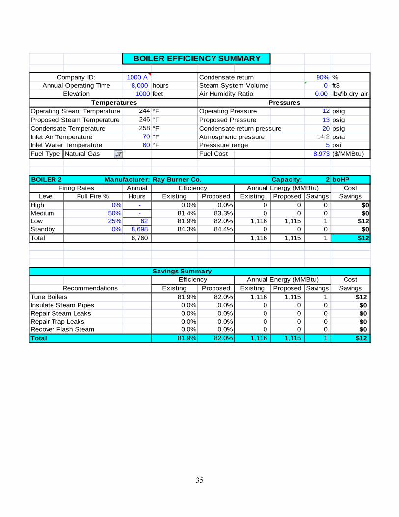
BOILER EFFICIENCY SUMMARY
1000 A Condensate return 90% %8,000 hours Steam System Volume 0 ft3
1000 feet Air Humidity Ratio 0.00 lbv/lb dry air
244 °F Operating Pressure 12 psig246 °F Proposed Pressure 13 psig258 °F Condensate return pressure 20 psig70 °F Atmospheric pressure 14.2 psia60 °F Presssure range 5 psi
Fuel Type Natural Gas Fuel Cost 8.973 ($/MMBtu)
BOILER 2 Ray Burner Co. Capacity: 2 boHPAnnual Cost
Level Full Fire % Hours Existing Proposed Existing Proposed Savings SavingsHigh 0% - 0.0% 0.0% 0 0 0 $0Medium 50% - 81.4% 83.3% 0 0 0 $0Low 25% 62 81.9% 82.0% 1,116 1,115 1 $12Standby 0% 8,698 84.3% 84.4% 0 0 0 $0Total 8,760 1,116 1,115 1 $12
Savings SummaryCost
Existing Proposed Existing Proposed Savings Savings81.9% 82.0% 1,116 1,115 1 $120.0% 0.0% 0 0 0 $00.0% 0.0% 0 0 0 $00.0% 0.0% 0 0 0 $00.0% 0.0% 0 0 0 $0
Total 81.9% 82.0% 1,116 1,115 1 $12
Repair Steam LeaksRepair Trap LeaksRecover Flash Steam
Recommendations
Company ID:Annual Operating Time
Elevation
Operating Steam TemperatureProposed Steam TemperatureCondensate Temperature
Tune BoilersInsulate Steam Pipes
Efficiency Annual Energy (MMBtu)
Temperatures Pressures
Efficiency Annual Energy (MMBtu)Firing Rates
Inlet Air Temperature Inlet Water Temperature
Manufacturer:
35

36

APPENDIX A
UTILITIES A.1. Energy Definitions An essential component of any energy management program is tracking energy. When utility bills are received, we record energy use and cost in a spreadsheet and get the appropriate graphs. A separate spreadsheet may be required for each type of energy used, such as oil, gas, or electricity. A combination might be merited when both gas and oils are used interchangeably in a boiler. In such a case we suggest using a common energy unit for a cost-benefit analysis that can represent most fuel options: the Btu.
We have prepared a utility spreadsheet analysis based on the information provided by you or your utility companies. The worksheets are in section A.3, Energy, Waste, and Production Accounting. They show how energy is used and help identify potential energy savings.
We use specific terminology and calculations in analyzing and discussing your energy, water, and waste expenses. Energy related terms and calculations are detailed below followed by those for waste and water. Electricity Definitions: Average Energy Cost. The total amount billed for 12 months of energy, divided by the total number of energy units. Each energy type (oil, gas, electricity, propane, etc.) has its own average energy cost. The average cost per energy unit includes the fees, taxes and unit cost.
Average Energy Cost = (Total Billed $) ÷ (Total Energy Units)
Average Load Factor. The ratio of annual electrical energy use divided by the average kilowatts (kW) and the hours in a year.
Average Load Factor = (Total kWh/yr) ÷ (Average kW x 8,760 hrs/yr)
Average Load Factor expresses how well a given electrical system uses power. A higher load factor yields lower average energy cost.
An example of how load factor applies: A large air compressor has high electric demand for small periods of time and is not a large energy user. It will usually have low load factor and relatively high demand charges. A smaller air compressor that runs for longer periods of time at higher part load efficiency will have higher load factor and lower demand charges.
Basic Charge. The fee a utility company can charge each month to cover their administrative, facility, or other fixed costs. Some companies have higher energy or power rates that compensate for no or low basic charge.
37

Energy. The time-rate of work expressed in kWh for electric energy. The common unit is million Btu. For a more complete description, see Power.
Energy = Work ÷ Time = (Force x Distance) ÷ Time
Incremental Demand Cost. It is the price charged by your utility company for the capacity to meet your power needs at any given time. Peak demand is the highest demand level required over a set period of time and is calculated by continuously monitoring demand levels. Demand is usually billed based on peak power, but charges such as facility charges and other fees billed per kW are also included in the incremental demand cost. If your utility company has stepped demand cost rates, the step with the greatest demand is considered in the incremental demand cost. If your utility company bills one set rate for all power needs, this value is used as the incremental demand cost.
Incremental Energy Cost (Electricity). It is cost of one more unit of energy, from current use. This cost is usually taken from your utility rate schedule. When all large meters are on the same rate schedule, the incremental energy cost is the cost from the highest energy tier, or tail block. To further clarify this method: if a company is charged $0.05/kWh up to 100,000 kWh, and $0.03/kWh over 100,000 kWh and they are consistently buying over 100,000 kWh each month, any energy savings will be calculated using the $0.03/kWh cost.
If your company has multiple meters on different rate schedules or tariffs, the incremental cost is calculated by adding electrical energy costs and dividing by the total electrical energy use.
Incremental Energy Cost = (Total kWh $) ÷ (Total kWh)
Minimum Charge. The least amount billed by a utility at the end of the billing period. Power (and Energy). The rate at which energy is used, expressed as the amount of energy use per unit time, and commonly measured in units of watts and horsepower. Power is the term used to describe the capacity the utility company must provide to serve its customers. Power is specified three ways: real, reactive and total power. The following triangle gives the relationship between the three. Total Power (kVA)
Reactive Power (kVAR)
Ө
Real Power (kW)
Real power is the time average of the instantaneous product of voltage and current (watts). Apparent power is the product of rms (root mean square) volts and rms amps (volt-amps).
Demand The highest electrical power required by the customer, generally averaged over 15 minute cycling intervals for each month. Demand is usually billed by kW unit.
38

Kilovolt Amperes (kVA) Kilovolt amperes are a measure of the current available after accounting for power factor. See the triangle on the previous page. Power is sometimes billed by kVA.
Reactive Power
Reactive power is measured in units of kVAR. Reactive power produces magnetic fields in devices such as motors, transformers, and lighting ballasts that allow work to be done and electrical energy to be used. Kilo Volt Amperes Reactive (kVAR) could occur in an electrical circuit where voltage and current flow are not perfectly synchronized. Electric motors and other devices that use coils of wire to produce magnetic fields usually cause this misalignment of three-phase power. Out-of-phase current flow causes more electrical current to flow in the circuit than is required to supply real power. kVAR is a measure of this additional reactive power.
High kVAR can reduce the capacity of lines and transformers to supply kilowatts of real power and therefore cause additional expenses for the electrical service provider. Electric rates may include charges for kVAR that exceed a normal level. These charges allow the supplying utility to recover some of the additional expenses caused by high KVAR conditions, and also encourages customers to correct this problem.
Power Factor
The ratio of real power to total power. Power factor is the cosine of angle θ between total power and real power on the power triangle.
PF = cos θ = kW ÷ kVA
Disadvantages of Low Power Factor • Increases costs for suppliers because more current has to be transmitted requiring greater
distribution capacity. This higher cost is directly billed to customers who are metered for reactive power.
• Overloads generators, transformers and distribution lines within the plant, resulting in increased voltage drops and power losses. All of which represents waste, inefficiency and wear on electrical equipment.
• Reduces available capacity of transformers, circuit breakers and cables, whose capacity depends on the total current. Available capacity falls linearly as the power factor decreases.
Low Power Factor Charges
Most utilities penalize customers whose power factor is below a set level, typically in the range of 95% - 97%, or kVAR greater than 40% of kW. Improving power factor may reduce both energy and power costs, however these are generally much less than savings from real power penalties enforced by electrical utilities. Energy savings are also difficult to quantify. Therefore in our recommendations, only power factor penalty avoidance savings are included.
39
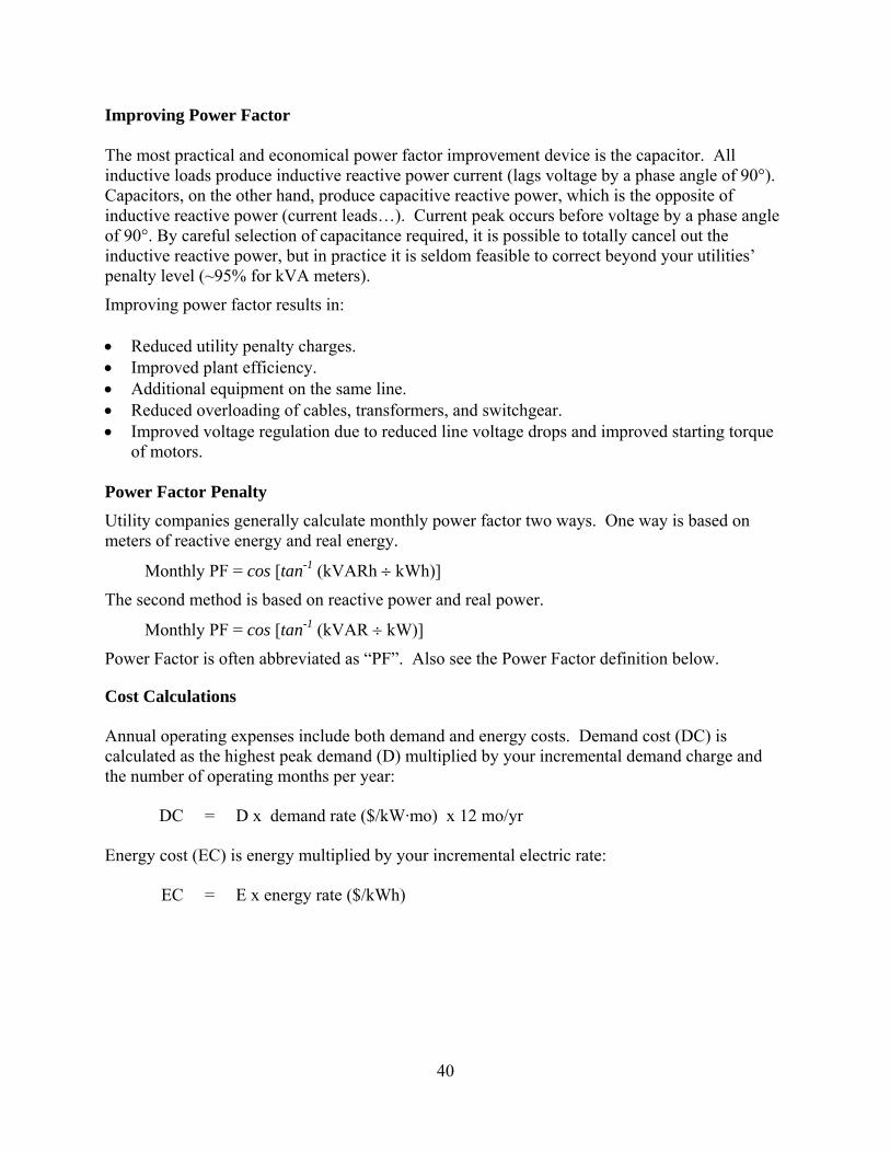
Improving Power Factor The most practical and economical power factor improvement device is the capacitor. All inductive loads produce inductive reactive power current (lags voltage by a phase angle of 90°). Capacitors, on the other hand, produce capacitive reactive power, which is the opposite of inductive reactive power (current leads…). Current peak occurs before voltage by a phase angle of 90°. By careful selection of capacitance required, it is possible to totally cancel out the inductive reactive power, but in practice it is seldom feasible to correct beyond your utilities’ penalty level (~95% for kVA meters).
Improving power factor results in:
• Reduced utility penalty charges. • Improved plant efficiency. • Additional equipment on the same line. • Reduced overloading of cables, transformers, and switchgear. • Improved voltage regulation due to reduced line voltage drops and improved starting torque
of motors.
Power Factor Penalty Utility companies generally calculate monthly power factor two ways. One way is based on meters of reactive energy and real energy.
Monthly PF = cos [tan-1 (kVARh ÷ kWh)]
The second method is based on reactive power and real power.
Monthly PF = cos [tan-1 (kVAR ÷ kW)]
Power Factor is often abbreviated as “PF”. Also see the Power Factor definition below.
Cost Calculations
Annual operating expenses include both demand and energy costs. Demand cost (DC) is calculated as the highest peak demand (D) multiplied by your incremental demand charge and the number of operating months per year:
DC = D x demand rate ($/kW·mo) x 12 mo/yr
Energy cost (EC) is energy multiplied by your incremental electric rate:
EC = E x energy rate ($/kWh)
40

Natural Gas Definitions:
Rate Schedules. (Or tariffs) specify billing procedures and set forth costs for each service offered. The state public utility commission approves public utility tariffs. For example: an electric utility company will set a price or schedule of prices for power and energy and specify basic and PF charges. A natural gas utility will specify cost to supply or transport gas and include costs such as price per therm, basic charge, minimum charges and other costs. Current rate schedules can often be found online at the utility company’s website. If you think your company belongs in a different rate schedule, your utility representative can help you best.
Tariff. Another term for rate schedule.
Therm. The unit generally used for natural gas (1 therm = 100,000 Btu), but sometimes it is measured in 106 Btu.
Commodity Rate. The component of the billing rate that represents the company’s annual weighted average commodity cost of natural gas.
Transportation. The movement of customer-owned natural gas from the pipeline receipt point(s)
Waste and Water Definitions: Average Disposal Cost. The average cost per pickup or ton of waste or other scrap material. This cost is calculated using all of the annual expenses to get a representative cost per unit of disposal.
Average Disposal Cost / Ton = (Total Disposal $) ÷ (Total tons removed)
Average Disposal Cost / Pickup = (Total Disposal $) ÷ (Total number of pickups)
BOD Charge. Charge levied by the sewer/water treatment utility to cover extra costs for high strength wastewater. High strength wastewater requires more intensive treatment by the utility and extra processing due to very low oxygen levels. BOD, biochemical oxygen demand, is a measure of how much oxygen will be used to microbiologically degrade the organic matter in the wastewater stream. State agencies such as a Department of Environmental Quality set BOD and other regulations that wastewater treatment facilities must meet to discharge treated water into nearby waterways. Your treatment facility may have ideas that could help lower the strength of your wastewater. Box Rental Charge. The fee imposed by the waste or recycling utility to cover costs of their receiving containers.
Disposal Cost. Incurred by the waste utility for disposing of your waste in a landfill or other facility. These charges increase when hazardous materials are present in the waste. Pickup Costs. The cost charged by the waste utility for each pickup of waste or recycling. This charge is usually applied when the utility is working on an “on call” basis. Pickup costs can also be a flat rate for a certain number of pickups per month.
41
42
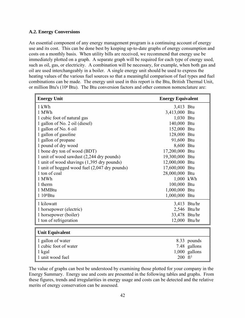
A.2. Energy Conversions An essential component of any energy management program is a continuing account of energy use and its cost. This can be done best by keeping up-to-date graphs of energy consumption and costs on a monthly basis. When utility bills are received, we recommend that energy use be immediately plotted on a graph. A separate graph will be required for each type of energy used, such as oil, gas, or electricity. A combination will be necessary, for example, when both gas and oil are used interchangeably in a boiler. A single energy unit should be used to express the heating values of the various fuel sources so that a meaningful comparison of fuel types and fuel combinations can be made. The energy unit used in this report is the Btu, British Thermal Unit, or million Btu's (106 Btu). The Btu conversion factors and other common nomenclature are:
Energy Unit Energy Equivalent
1 kWh 3,413 Btu 1 MWh 3,413,000 Btu 1 cubic foot of natural gas 1,030 Btu 1 gallon of No. 2 oil (diesel) 140,000 Btu 1 gallon of No. 6 oil 152,000 Btu 1 gallon of gasoline 128,000 Btu 1 gallon of propane 91,600 Btu 1 pound of dry wood 8,600 Btu 1 bone dry ton of wood (BDT) 17,200,000 Btu 1 unit of wood sawdust (2,244 dry pounds) 19,300,000 Btu 1 unit of wood shavings (1,395 dry pounds) 12,000,000 Btu 1 unit of hogged wood fuel (2,047 dry pounds) 17,600,000 Btu 1 ton of coal 28,000,000 Btu 1 MWh 1,000 kWh 1 therm 100,000 Btu 1 MMBtu 1,000,000 Btu 1 106Btu 1,000,000 Btu
1 kilowatt 3,413 Btu/hr 1 horsepower (electric) 2,546 Btu/hr 1 horsepower (boiler) 33,478 Btu/hr 1 ton of refrigeration 12,000 Btu/hr
Unit Equivalent
1 gallon of water 8.33 pounds 1 cubic foot of water 7.48 gallons 1 kgal 1,000 gallons 1 unit wood fuel 200 ft3
The value of graphs can best be understood by examining those plotted for your company in the Energy Summary. Energy use and costs are presented in the following tables and graphs. From these figures, trends and irregularities in energy usage and costs can be detected and the relative merits of energy conservation can be assessed.

APPENDIX B
LIGHTING
B.1 Lighting Worksheet Definitions The following lighting inventory and any lighting worksheets contained in the report use information obtained during the on-site visit to determine any potential energy savings related to lighting improvements. In all cases the value in the Savings column is the existing value less the proposed value. The terminology and calculations are described as follows: PLANT Building. A description of the building if the plant includes several buildings. Area: The lighting calculations may refer to a specific location within the building. Recommended Footcandles. The recommended footcandle levels come from the Illuminating Engineering Society (IES) Lighting Handbook. Average Demand Cost (D$). The demand cost ($/kW-month) is taken from the appropriate rate schedule of your utility. Winter and summer rates are averaged, if necessary. Average Energy Cost (E$). The energy cost ($/kWh) is taken from the appropriate rate schedule of your utility for the least expensive energy block. Winter and summer rates are averaged, if necessary. Labor Cost ($/H). The cost of labor is estimated for operating and installation cost calculations. FIXTURES Description (FID). Fixture type, size, manufacturer, or catalog number may be included here. Quantity (F#). The number of fixtures in the area are recorded during the site visit. Operating Hours (H). The number of hours which the lighting fixtures operate each year. Use Factor (UF). The fraction of fixtures that are used multiplied by the fraction of operating hours (H) that the lights are on. Lamps/Fixture (L/F). The number of lamps in each fixture. Ballasts/Fixture (B/F). The number of ballasts in each discharge fixture.
43
Cost (FC). The cost of the existing and proposed fixtures can be compared when modifying or replacing fixtures. LAMPS Description (LID). Lamp type, size, manufacturer, or catalog number may be included here. Quantity (L#). The number of lamps can be calculated from the number of fixtures and the number of lamps per fixture:
L# = F# x L/F Life (LL). Lamp life is defined as the number of operating hours after which half the original lamps will fail. The life recorded here is based on 3 operating hours per start. This provides a more conservative estimate of lamp life than using longer hours per start. Replacement Fraction (Lf). The fraction of lamps that normally can be expected to burn out during a year can be calculated from the operating hours, the use factor, and the lamp life: Lf = H x UF / LL Watts / Lamp (W/L). The rated lamp power does not include any ballast power, which is included in the Ballasts section. Lumens (LM). Lamp output is measured in lumens. Lumens are averaged over lamp life because lamp output decreases with time. Cost (C/L). The retail cost per lamp is entered here. BALLASTS This section applies only to discharge lamps with ballasts. This section will be blank for incandescent lamps. Description (BID). Additional information such as type, size, manufacturer, or catalog number may be included here. Quantity (B#). The number of ballasts can be calculated from the number of fixtures and the number of ballasts per fixture: B# = F# x B/F
44

Life (BL). Ballast life is determined from manufacturer's data. A life of 87,600 hours for a standard ballast and 131,400 hours for an efficient ballast is used in the calculations. Replacement Fraction (Bf). The fraction of ballasts normally expected to burn out during a year can be calculated from the operating hours, the use factor, and the ballast life: Bf = H x UF / BL Input Watts (IW). Ballast catalogs specify ballast input watts that include lamp power. The input wattage varies for different combinations of lamps and ballasts. Cost (BC). The retail ballast cost is entered here. POWER AND ENERGY Total Power (P). For incandescent lamps total power is the product of the number of lamps and the watts per lamp. P = L# x W/L (Incandescent Lamps) For discharge lamps total power is the product of the ballast input watts and the number of ballasts: P = B# x IW (Discharge Lamps) Energy Use (E). The annual energy use is the product of the total power, the use factor, and the annual operating hours: E = P x UF x H / (1,000 watts/kilowatt) LIGHT LEVEL CHECK Total Lumens (TLM). The existing and proposed lumen levels are summed for all lamps. TLM = L# x LM Footcandles (FC). Light is measured in units of footcandles. The existing footcandle level (FC0) is measured, while the proposed level (FC1) is determined from the ratio of the proposed total lumens (TLM1) to existing total lumens (TLM0) times the existing footcandle level. FC1 = FC0 x (TLM1 / TLM0) The proposed footcandle level can then be compared to both the existing and the recommended levels to determine if there will be adequate light for the work space.
45

Lumens / Watt (LM/W). The total lamp output in lumens divided by the total power is a measure of lighting efficiency. LM/W = TLM / P ANNUAL OPERATING COST Power Cost (PC). The annual demand cost is the total power times the average monthly demand cost from the worksheet times 12 months per year: PC = P x D$ x 12 months/year Energy Cost (EC). The annual energy cost is the energy use times the electricity cost from your utility rate schedule: EC = E x E$ Lamp O&M Cost (LOM). Operation and maintenance costs are the sum of lamp and labor costs for replacing the fraction of lamps (L# x Lf) that burn out each year. LOM = L# x Lf x [LC + (0.166 hours x $/H)] We assume that two people can replace a lamp and clean the fixture and lens in about five minutes (0.166 man-hours/lamp), replacing lamps as they burn out. Ballast O&M Cost (BOM). Operation and maintenance costs are the sum of ballast (BC) and labor costs ($/H) for replacing the fraction of ballasts (B# x Bf) that burn out each year. BOM = B# x Bf x [BC + (0.5 hours x $/H)] We assume that one person can replace a ballast in about thirty minutes (0.5 man-hours/ballast), replacing ballasts as they burn out. Total Operating Cost (OC). The sum of the annual power and energy costs and lamp and ballast O&M costs. OC = PC + EC + LOM + BOM
46

IMPLEMENTATION COST The implementation costs depend on whether refixturing, group relamping, or spot replacing of lamps and ballasts is recommended. Refixturing
Materials: The cost is the cost per fixture (C/F) times the number of fixtures (F#) plus the lamp cost (LC) times the number of lamps (L#).
M$ = F# x (C/F) + L# x C/L
Labor: The labor cost includes the removal of the existing fixtures and the installation of the recommended fixtures.
Group Relamping
Materials: When replacing all lamps at one time (group relamping), the cost of materials can be found from
M$ = L# x C/L
Labor: We estimate the labor cost for group relamping to be one half the cost of replacing each lamp as it burns out. We assume that two people can replace two lamps and clean the fixture and lens in about 5 minutes (0.083 man-hours/lamp, H/L). Because relamping does not require a licensed electrician, the labor rate for relamping is often lower than the labor rate for fixture replacement. To calculate the total labor cost for group lamp replacement we calculate the labor cost of group replacing all of the lamps.
L$GROUP = L# x H/L x $/H Spot Replacement of Lamps & Ballasts
Materials: When replacing lamps only as they burn out (spot relamping), we use the cost difference (LC1 - LC0) between standard and energy-efficient lamps for all lamps.
M$ = L# x (LC1 - LC0)
When replacing ballasts only as they burn out (spot reballasting), we use the cost difference (BC1 - BC0) between standard and energy-efficient ballasts for all ballasts.
M$ = B# x (BC1 - BC0)
Labor: There is no additional labor cost.
47
48
Total Cost (IC). Total implementation cost is the sum of materials and labor cost IC = M$ + L$ SIMPLE PAYBACK. The simple payback (SP) is calculated on each lighting worksheet. SP = IC / OC
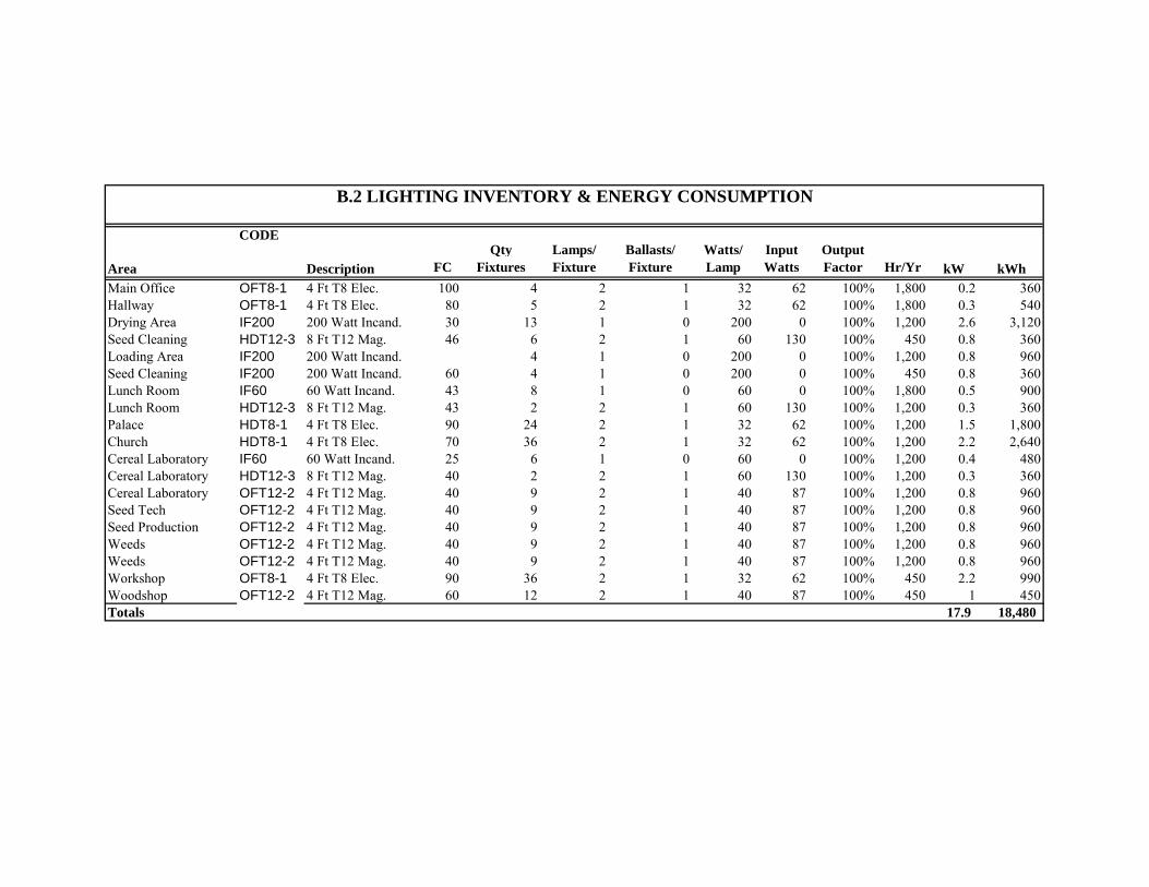
B.2 LIGHTING INVENTORY & ENERGY CONSUMPTION
CODE
Area Description FCQty
FixturesLamps/ Fixture
Ballasts/ Fixture
Watts/ Lamp
Input Watts
Output Factor Hr/Yr kW kWh
Main Office OFT8-1 4 Ft T8 Elec. 100 4 2 1 32 62 100% 1,800 0.2 360Hallway OFT8-1 4 Ft T8 Elec. 80 5 2 1 32 62 100% 1,800 0.3 540Drying Area IF200 200 Watt Incand. 30 13 1 0 200 0 100% 1,200 2.6 3,120Seed Cleaning HDT12-3 8 Ft T12 Mag. 46 6 2 1 60 130 100% 450 0.8 360Loading Area IF200 200 Watt Incand. 4 1 0 200 0 100% 1,200 0.8 960Seed Cleaning IF200 200 Watt Incand. 60 4 1 0 200 0 100% 450 0.8 360Lunch Room IF60 60 Watt Incand. 43 8 1 0 60 0 100% 1,800 0.5 900Lunch Room HDT12-3 8 Ft T12 Mag. 43 2 2 1 60 130 100% 1,200 0.3 360Palace HDT8-1 4 Ft T8 Elec. 90 24 2 1 32 62 100% 1,200 1.5 1,800Church HDT8-1 4 Ft T8 Elec. 70 36 2 1 32 62 100% 1,200 2.2 2,640Cereal Laboratory IF60 60 Watt Incand. 25 6 1 0 60 0 100% 1,200 0.4 480Cereal Laboratory HDT12-3 8 Ft T12 Mag. 40 2 2 1 60 130 100% 1,200 0.3 360Cereal Laboratory OFT12-2 4 Ft T12 Mag. 40 9 2 1 40 87 100% 1,200 0.8 960Seed Tech OFT12-2 4 Ft T12 Mag. 40 9 2 1 40 87 100% 1,200 0.8 960Seed Production OFT12-2 4 Ft T12 Mag. 40 9 2 1 40 87 100% 1,200 0.8 960Weeds OFT12-2 4 Ft T12 Mag. 40 9 2 1 40 87 100% 1,200 0.8 960Weeds OFT12-2 4 Ft T12 Mag. 40 9 2 1 40 87 100% 1,200 0.8 960Workshop OFT8-1 4 Ft T8 Elec. 90 36 2 1 32 62 100% 450 2.2 990Woodshop OFT12-2 4 Ft T12 Mag. 60 12 2 1 40 87 100% 450 1 450Totals 17.9 18,480